building information modeling – instructional interfacing...
TRANSCRIPT

Page 1 of 73
Design Data Building Solutions
DESIGN DATA Building Information Modeling – Instructional interfacing information for SDS/2 Detailers
This document is written by James Schwartz, and may not completely reflect the opinions of Design Data.
Issue 1 ‐ Wednesday, September 29, 2010
Introduction
Have you been told by the fabricator or general contractor that this is a BIM project, and when you have inquired what does that mean, you get a response, “We are not too sure” or “We will be sending you a model to import to your software and we want one back.” There are a ton of articles floating around, many case studies and books citing millions of saved dollars and dramatically reduced schedules that will tantalize any pallet. In this document I intend to briefly shed some light on this topic, and what you need to know from the Design Data SDS/2 side of the BIM world.
History
Forms of BIM have been around for quite some time and have been practiced by many companies on different softwares. Some may remember in the late 90’s EDI (Electronic Data Interchange), or VDC (Virtual Design Construction). BIM (Building Information Modeling) in its primitive stages, generally consisted of exchanging model information from design/development and Engineering software to steel detailing packages. Design Data was one of the pioneers in this process. From about 2003 and up, the term BIM and later IPD (Integrated Project Delivery) have appeared on the scene, and technology has allowed this exchange of model information to extend past just the structural steel manufacturing stage of a project. This expansion has generated rumors and created some confusion for people, considering how the software venders are vying for a piece of the BIM pie. Some may remember the same thing occurring back in the late 80’s and early 90’s when the same thing occurred with the steel detailing packages. An important point to remember is that BIM is not any specific software, but software is required for the transmission of the data which is used to efficiently build a project. BIM is a process. These points will be expressed throughout this document.
A history would not be complete without mentioning the different transfer file formats. In the early and mid 90’s in the USA, the SDNF (Steel Detailing Neutral File) file format emerged, as well as the 3D DXF and PML to mention the ones particular to the steel industry. An issue began to arise with the file formats, as each software vendor would add their own flavor to the format, restricting true interoperability between the software products. The AISC, and a few people from software companies, industry and education, grabbed the “bull by the horns” and decided to endorse a standard file format that could be used by all steel software developers. About 2000, the CIS/2 format was chosen and endorsed by the AISC and is currently still the only endorsed file format for model interoperability between 3D structural steel modeling software. More recently the IFC file format came on the scene endorsed by the IAI (International Alliance for Interoperability), now known as buildingSMART. The overall difference between the IFC and CIS/2 format will be discussed in the Common Data Transfer File Formats, but it is important to note that the IFC format was readily

Page 2 of 73
adopted by the design/development side of the industry. i.e. Architectural, Engineering and General Contractors.
Ever pushing forward, the industry has now moved past the 3D to the 4D (Time and scheduling) and 5D (quantities and costs). Putting aside the politics and the age old adversities between the design/development and manufacturing of the structure, at this date, both the IFC, CIS/2, VRML, DGN, DWG, DWF, DWFX and DXF files, to name a few, are being used depending on the software and application in the projects life cycle.
A Definition of BIM
Each person has a slightly different definition of BIM. As a rule I generally will ask the person that I am dealing with what is their interpretation of BIM, or how do they envision the implementation of the model in the projects workflow. This gives me a platform to work off of. Currently BIM is predominantly being used for clash detection, but this is rapidly expanding as the market requires more productivity. Many would consider using the model for clash detection as partial BIM. BIM very simply put, is the exchange of information between different disciplines within the construction industry, using electronic data. This data can be either transferred between different software or different software reading information from a collective data base. This electronic data is used to enhance communication between the different disciplines, in order to reduce expensive rework on the field due to miscommunication errors, to reduce redundant work, to speedily create documentation, phasing and scheduling and to also be used for the building’s operation throughout its life cycle. The primary source for this data exchange is the 3D model which, in theory, contains all the information pertaining to the project from all the disciplines involved. From the model, other forms of electronic information can be derived for use in the project from inception to demolition.
A Definition of Interoperability
Interoperability is yet another disputed term. In short this means that different softwares are able to communicate information amongst themselves. Where the dispute arises is some companies will use API’s (Application Program Interface) for this communication, which will force users to use only software that write to that specific software’s API. The opposing side feels that a standard and accepted file format is to be used, which allows anyone to write to that format. The advantage to using a file format is that it creates a stable consistent standard that can be corporately maintained and enhanced, where as the API moves the industry more toward being propriety, as well as having version and maintenance issues. Does SDS/2 have an API, the answer is yes. Design Data uses Python for their API and more information is constantly being exposed through Python.
Where two worlds collide
I will start with the line that exists between what I call the design/development side of the project and the manufacturing side of the project. What BIM does is it put the emphasis of completion more upon the development side of the project, thereby reducing RFI’s change orders and finally manufacturing and erection issues. Simply put, build the project in the 3D digital world, before reality sets in. One of the questions I would ask when training people from different disciplines in the industry is, “Tell me about your best and worst project?” In each case the best project was the one where all the disciplines worked together, communicating right from the “kick‐off” meeting and

Page 3 of 73
maintained constant communication throughout the project. Each person in the group would be utilizing the talents of each discipline, to create a successful project. In almost all cases, this response was from projects where 3D digital models were not even part of the workflow. So why use the 3D digital model? Because it is a great container of information. 3D allows us to see without the need to imagine or interpret 2D into the 3D world, thus enhancing communication, and thereby reducing errors. 3D also allows conflicts to be caught quicker, reducing the schedule.
So where is the collision of the two worlds? It comes when we try to merge the design/development of the project and the manufacturing side. The design/development side of the fence is fluid and constantly changing. It will then gradually become more solid. Once it becomes more solid, the “Issued for Construction” information will be released. This may come in either 2D and 3D form or only in 3D or only in 2D. Once the manufacturing process has begun, the train is started and not easily deviated or stopped.
The collision also occurs between the different disciplines. For example; the engineer will design and analyze the structure using the centerlines of the members. For analysis of the structure, the engineers do not need to add members sloped on the drainage roof, or openings to be exact to the 1/16”, or worry about erection issues, but all these issues are critical to the steel detailer. From this example, we can also see that the manufacturing model will be the most accurate rendition of what the final model will look like, not the Architects or Engineers.
The colliding of the worlds is not bad, but understanding and protocols are required to make sure the collisions are not harmful to the flow of the project. Even the best software does not correct the issues, it only facilitates communication between the people working on the project, to resolve the conflicts.
Software –what dreams are made of?
There are many software packages out there, but I will focus on the most common. There are some software companies that claim that they do everything and you only need their software for the complete project workflow, but even those softwares must interface with other software either through an API or a file format to accomplish all that is required in a building project.
Let’s break it down into two major groups. First you will have the collaborative, collective or coordination softwares. These are the software that function as collectors of the different models. They can bring in information from other disciplines and bring all the digital models together. The digital models can come from a suite of the companies own softwares, or bring in digital models with their respective information from other software. The top collaborative model software would be AutoDesk’s Revit®, and Navisworks© , which are by far the industry leaders, then the Bentley© suite of products, Solibri Model Checker®, Intergraph’s SmartPlant® , Vico Constructor© and Tekla Structures®. Revit, Bentely Systems, Smartplant and Tekla collaborate within their own suit of software well, but may be limited working outside of their own software suits or their affiliated softwares.
Then you will have the products that are not the collaborative modeling products, but contribute to the collaborative products. These products are no less part of the BIM process, and supply the information that the collaborative products do not have or do not do well. We are all familiar with
Page 4 of 73
the phrase “Jack of all trades, and master of none”. Every software has areas where they excel, but they do not excel in all areas.
Design Data’s SDS/2® is one of these feeder softwares. Other examples of feeder products would be the engineering and analysis software, the MRP software, estimating and document control software, and propriety products.
Industry Players
The BIM world is rapidly expanding. At one time digital models were transferred between engineers and detailers, but since the early 2000’s the digital models are now used by the Architect, Engineer, General Contractor, Fabricator, Detailer, Mechanical, Electrical, Plumbing, Erectors, Grating manufactures, joist manufacturers and facility operators to name a few. Because of this it is imperative that the model is accurate and contains all the information possible. Take the steel detailer as an example. In days of old, hole dimensions could be changed only on the 2D image, as an example, but now it is imperative that the digital model be completely up to date. All the elements need to be shown correctly and in their proper locations due to; CNC which is extracted from the model, for clash detection, for erection and for grating manufacturers that use the model for layout.
BIM means a completely new price structuring of the industry, for example take the money lost because of delays, errors, litigation and omissions from the project and then reduce the bottom line cost by spending some of the money and time up front at the beginning of the project. The old adage “An ounce of prevention…” comes to mind.
Common Data Transfer File Formats
A common misunderstanding is that a specific file type is associated with BIM. This is a misconception. BIM consists of many file types, from IFC and CIS/2 to DGN and DWG. The file type and the API are just the communication tools that are used between the various softwares that are utilized in the BIM process.
You can think of file types as different languages used to communicate. Some people can understand and speak only one language, where others can understand and speak several languages. Some people can understand a language but not speak it well and others can understand and speak many languages, but not master any of them well. The same applies with the transfer file formats and API’s.
Listed below are a few file format descriptions:
IFC – People incorrectly associate BIM as the IFC format. IFC is one of the file types used in BIM, but it is not BIM, nor is this file format required to be used in BIM. This is just one of the options. The IFC file format is very useful for the model collaborative softwares, because it is very wide, meaning that you can have a door knob or a tree, but it currently lacks the depth of information required for structural steel.
CIS/2 ‐ This is the AISC endorsed file format for structural steel. It is extremely data rich concerning structural steel, but is not wide, lacking the data for material types such as concrete. CIS/2 is also very structured in comparison to the IFC format which currently is less structured.

Page 5 of 73
SDNF 2.0 and 3.0 ‐ this is an older format that has been used for years. It lacks the width of IFC and the depth of CIS/2. It is a propriety format and has been, for the most part, replaced by CIS/2 and IFC.
VRML ‐ this format contains only the 3D objects for visualization with minimal information. DXF, DWG and U3D are like the VRML and are generally just for generating the 3D objects in the digital model for clash detection.
XML – Can be used in both the 3D and 2D world and is very versatile. One of the limitations with this Extensible Mark‐up Language is that any schema can be developed, therefore moving it more towards a propriety format. XML is still a very useful file format, especially where the World Wide Web is concerned.
ISM – This is relatively new by Bentley, yet the concept has been around for quite some time. Simply put, there is a central data base model and the different software will push and pull the information to and from this data base. To my knowledge, Revit and Tekla are already writing to this data base.
Formats like DWG, DWF, DWFX and DGN are also used to transfer 3D models and attached information. SDS/2 does not currently import or export 3D DWG or DGN files. Concerning DWF and DWFX, these file formats can only be imported into SDS/2 version 7.2 and up.
Other formats exist as well for the exchange of information that is not 3D, but yet is part of the BIM world i.e. KISS, XML, Fabtrol XSR, DSTV.
There are many other 3D formats, but these are out of this scope, since SDS/2 does not either import or export the other file formats.
Software and their imports and exports
This section will begin with some generalities and then the specific software will be covered. Due to the nature of software enhancements, some of the information listed here will likely change over time.
General Information
In my experience with BIM coordinators, SDS/2 has left a bad taste in their mouths. This is due to several reasons such as;
Models not being kept up to date or complete with all the members and material properly positioned.
VRML models that were not translated and/or rotated correctly.
o In version 7.218, the VRML export has been greatly enhanced, having piecemarks and status colors exported, and more rotational options.

Page 6 of 73
Lack of information from the VRML files.
o IFC files will generate more data aside from the 3D objects.
In version 7.218 sequence and status information has been added to the IFCPROPERTYSET. See the section on Navisworks for more information.
File sizes too large, therefore requiring the building to be imported in sections.
o In all versions of 7.2 you can export only the steel that is selected from the model.
Using masking in status you can hide the dummy members used to create connections, as well as, hide sequences, making selection in the model easier.
You will come across BIM coordinators that will request 3D DWG files. There are several reasons for this;
They are files which are native formats for Autodesk products.
The majority of MEP contractors are still using AutoCAD, and will be for quite some time.
o A lot of these MEP subcontractors will not have the latest and greatest hardware, making it difficult to use large files, such as DXF.
o MEP uses the structural model to prevent clashes while they layout the mechanical, electrical and plumbing.
Before you panic about how to export a 3D DWG file, there are a few questions that you can ask.
Will an IFC file suffice, especially if they are using Navisworks, Revit, AutoCAD Architecture or Solibri Model Checker.
o To export the IFC file format you must purchase the ModeLINK module from Design Data.
If Navisworks only is to be used, and only clash detection done, a VRML file may suffice, since Navisworks imports VRML files. VRML does not require the purchase of ModeLINK.
If a 3D DWG is absolutely required, a DXF to DWG converter can be downloaded from the web. From SDS/2 a 3D DXF can be exported using ModeLINK and then converted to a 3D DWG. The one I currently am using is “Active DXF DWG converter” www.autodwg.com.
o In version 7.220 a 3D DWG export is added, which will soon be available to the public.
o Version 7.219 and below do not have a translation option with the DXF export to move the model origin. Origin is discussed further in this section of the document.
The IFC or DXF can also be converted to a 3D DWG using Revit or AutoCAD Architecture.
Page 7 of 73
Another option may be the DWF or DWFX format. These files can be created using Navisworks 2010 or 2011 or a downloaded converter. I have not researched prior Navisworks versions.
You may read or hear the term “Clash free models are to be supplied”. What does this mean? From the coordinators I have spoken with it means that the model you are supplying do not have any clashes within itself. With SDS/2 this should not be a problem. Asking for clarification on statements such as these is always the best practice.
Before beginning a project, verify which collaborative software and its version are being used. You can also ask if the model is only required for clash detection. As mentioned previously, this will affect which file format is to be used. The more you ask, the better for all involved parties.
Concerning Navisworks, you may want to send both a VRML and an IFC. This will be discussed further in the Navisworks portion of the document.
If SDS/2 version 7.1 is used, the ability to export IFC and import DWF/DWFX does not exist, but you can convert the project to version 7.2 just to be able to export the IFC file or to clash detect in SDS/2 using imported DWF files.
o It is import to run a Verify and Fix after the convert. Maybe twice for good luck!
If possible, run a few preliminary tests to establish the accuracy and issues that may arise, such as rotation and location of the model.
BIM coordinators may request to have a Navisworks file sent to them. SDS/2 does not support the export of native Navisworks files NWC, NWF or NWD, which means that you will require the purchase of Navisworks. It’s not called Big Investment of Money for nothing.
A critical factor is, at what time does the BIM coordination on the project begin. Unfortunately, in many cases the BIM coordination team is brought into the project after the architectural, structural design and steel detailing has begun and their respective models have been built. You know this has occurred when you get a call after you have finished inputting the steel model, and you are told you need to supply a model and the given origin point for the model is somewhere in Siberia. The origin point of the model is very import in order to line up the digital models from the various disciplines. Getting this information before you begin inputting your model will make your life a little easier, but if you have already input the model, SDS/2 has the ability to translate the origin on the IFC (version 7.218), VRML, and CIS/2 file exports. Refer to the Navisworks portion of the documentation for more information. Below are a few points and tips about origin points.
If you are lucky, you will receive a specific grid intersection for the 0,0,0 origin location, but this will likely not be the case. You may receive either a 2D or 3D DWG and you will be asked to use the origin from the supplied files. If you have received a 2D or 3D DWG file and you are required to determine the origin, I offer two possible methods to determine the origin.
o If you have Navisworks, you can import the DWG file. From there you can use the measure tool to determine the origin.
Page 8 of 73
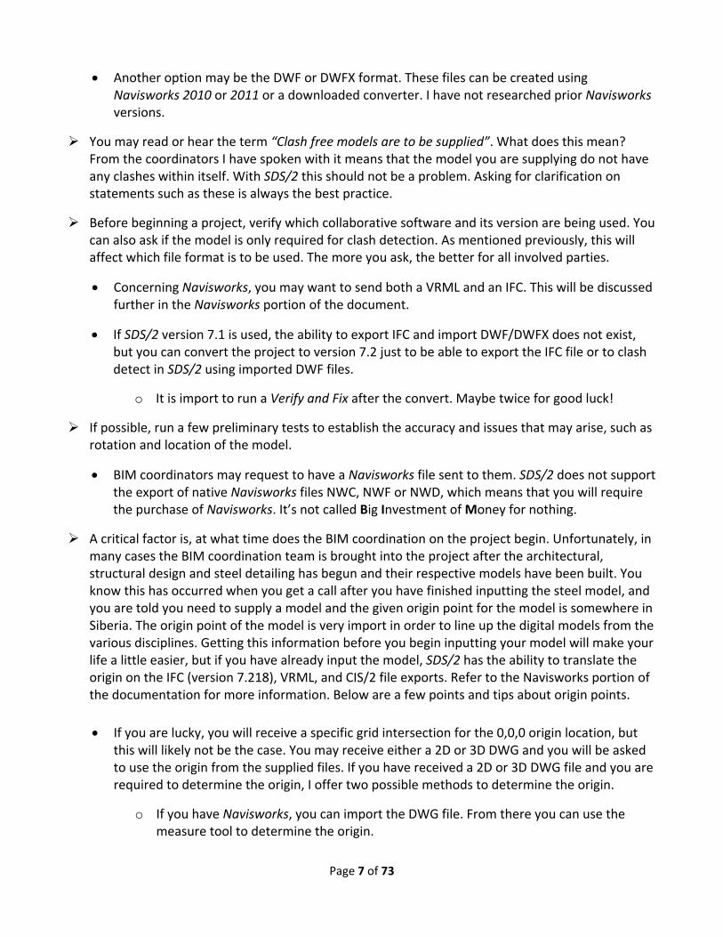
o If you do not have Navisworks, you can download for free the Autodesk’s DWG TrueView 2011 and use the measure tool. The following steps will give a brief description on how to obtain the origin from a 2D DWG. 3D will be determined in the same manner.
NAVISWORKS 2011
1. Open the DWG in Navisworks.
2. Using the Measure Tool, select the Point to Point option and locate a point. In this example, a bottom left corner column was used. You will see
the Start point X,Y,Z coordinate displayed. Now you have the point at which you will have to start your
model, or the distance that you will have to translate your model on export. Since the DWG is only 2
dimensional, the Z value should be the underside of the base plate, but again, this will have to be confirmed.

Page 9 of 73
DWG TRUEVIEW2011
1. Open the DWG in DWG TrueView2011.
1. Zoom into a known location such as the center of the bottom left column, or a grid intersection.
2. Select the Measure – Distance tool.
3. For the first point type in the Specify first point; the values 0 <TAB> 0 <TAB>. You will see the lock appear in each field.
4. Left click the mouse, which will select the first point which is the origin (0,0) location.
5. Then select the bottom left column center, or your determined grid intersection. Be sure to be careful selecting the points.
6. Use your Navigation Wheel to zoom out of the view the until you can see the dimensions.

Page 10 of 73
7. You will now have the X and Y values for the distance from the drawing’s origin to your bench mark for the model. In this example, you would locate in SDS/2 your bottom left column at X = 1109’‐4 3/8”, Y = 1118’‐9 1/4” and Z = underside of base plate.
The next issue is the rotation of the model. For example, the Architect may have the model in the exact world coordinates, which for example purposes may have the building rotated in a northwest position. In SDS/2, if you have a northwest position for your north setting, your column faces for erection will be indicated as such. You can still square off the building, but this will require the model to be rotated when imported into the collaborative software. Navisworks and Solibri Model Checker have the ability to rotate the model after importation.
The BIM coordinator may encounter with the VRML, 3D DXF and 3D DWG scale issues. These issues will be covered in the Navisworks portion of the document.
Establish the method of transfer, i.e. FTP site, with a carbon copy of the email to all concerned parties.
Establish a naming convention and directory structure for the files being transferred. For example, each discipline will have a folder name with subfolders with dates.
Determine the deliverables, for example, will only a model be sent, or will there be 2D images in PDF or dwg format.

Page 11 of 73
Create sequences in your models for concrete, embeds, decking, slabs, imports, mechanical, dummy members, slabs, and set the items accordingly.
Items such as embeds, which will be required to be broken down into sequences, can be named Embed‐1, Embed‐2,etc.
o Be careful that the naming convention for the sequencing will not cause issues with MRP products such as Fabtrol.
Use the statusing options in SDS/2 such as HOLD, Submitted for approval, Erected, etc. This information can be transferred with IFC and VRML exports to the collaborative modeling programs, and will be useful for BIM coordinators.
Establish responsibilities and methods of communication.
An example of responsibilities would be the handrail. The Architect will need to have a representation of the handrail for the client, but the engineer need not spend the time adding in the rails and posts except for critical locations. This is because the rails and posts will be changed when it comes time to be detailed due to the constructability of the rails. After all, the manufacturing models are the closest to what is to be built.
Another example would be the reviewing of the structural steel shop drawings, by the engineer. It is not the responsibility of the engineer to review the shop dimensions or shipping marks. Unless of course the engineering company feels it needs to be responsible for this.
If you are to receive a model for importation into SDS/2 from the engineer and the IFC format is used, it may be better that connections are not exported from the source model and the members are modeled from members intersecting point to intersecting point.
With engineering transfers, it is preferable that the file’s members are mapped, meaning that
columns on a multi‐level structure extend to the splices and not floor to floor.
When exporting to engineering products, many will require an analytical CIS/2 file. If this is the case, node numbering will be required. This currently can only be done through the EAD product.
Determine the revision procedures for the models, and the method of transfer for addendums and clash results.
The concept of round tripping or bi‐directional transfer, is only possible if a tracking number or GUID for each component is assigned and maintained. The GUID is an id that allows the software to know which information is attached to what component. Without a GUID, the software will not know which member the information is to be attached to during the transfer.

Page 12 of 73
Note that a GUID is represented differently in ASCII form from file format to file format and software to software. For example, a CIS/2 representation of a GUID is not the same as an IFC.
With SDS/2, the revised model can be imported into a new project and then the master model can then be updated manually by the detailer.
Specific software
The following section will contain information about some of the individual softwares used in the
industry.
Navisworks® (2009, 2010, & 2011)
Currently, the most popular collaborative software used in the industry by Contractors and BIM coordinators is Navisworks. This product was such a success that around 2008, it was purchased by Autodesk®. Navisworks is used to pull together all the different digital models from the different modeling packages due to its extensive amount of accepted file formats. It is like the PDF of the modeling industry. Once these models are brought together, clash detection and animations can be performed. Some comments I have read about it is that it currently is easier to use out of the box than its competitors.
As mentioned earlier in the documentation, it is becoming more common for BIM coordinators to request a model in the native Navisworks formats NWC, NWF or NWD, with the model positioned and oriented as per the Architect’s model. This will require the detailer to purchase Navisworks, unless you already have a package that can create the native Navisworks file formats such as; Autodesk AutoCAD®, Revit®, 3ds Max®, Bentley Microstation® and Graphisoft ArchiCAD®.
In this section, I will give tips on exports from SDS/2 and the results of importing the files into Navisworks2010 and 2011. Tips will be also given on using Navisworks for those that have or will be purchasing Navisworks.
General Points
Files from SDS/2 that can be imported into Navisworks: o 3D DXF – requires the purchase of ModeLINK. o 3D DWG ‐ requires the purchase of ModeLINK and SDS/2 version 7.220 and up. o IFC ‐ requires the purchase of ModeLINK. o CIS/2 ‐ requires the purchase of ModeLINK, and a minimum Navisworks release of
version 2010. o VRML – no purchase of ModeLINK required.
Within Navisworks models can be rotated, relocated and scaled, but it is preferred to not have to perform any of these actions.
Navisworks uses the X,Y,Z coordinate system, which by default has the Z axis up and the Y axis north, but when Navisworks reads a file it will set the coordinate direction of the scene as per

Page 13 of 73
the initial file that is read. The coordinate system from the first model will be maintained as long as that model remains in the scene.
Each model will have its own unit settings, unless the file has been saved as a NWD format.
VRML (from SDS/2)
The VRML format has its pros and cons. Of all the formats, with VRML, it is imperative to know which model is being brought into Navisworks first. This will determine how you are to export the VRML from SDS/2.
o Pros:
Accurate representation of the model, including curves, spiral offsets, angle of twists, bends, copes, cut layouts and preparations.
Options to add bolts, holes and welds.
Model Color or Surface finish exported and read correctly into Navisworks.
Set Status colors come across if exported from version7.218 up.
Direct import into Navisworks.
If the VRML was created from a CIS/2 file using the SteelVis translator (cic.nist.gov), sequences and more member data is imported.
Small file size.
For example a 2464 member project of 457.461 tons with no curved members will generate the following file sizes;
o 121 meg = DXF (from SDS/2 with no bolts, holes or welds)
o 64 meg = DWG (converted from DXF with no bolts, holes or welds. Version 7.220 will have a direct export to DWG and the file size will be approximately the same.)
o 27.4 meg = IFC (with no bolts, holes or welds)
o 18.5 meg = CIS/2
o 16.5 meg = VRML (from SDS/2 with no bolts, holes or welds)
The building can be exported from selection in the model, which will allow smaller sections to be exported, which can be appended together in Navisworks.
VRML export is free in SDS/2

Page 14 of 73
o Cons:
If rotation is not done correctly on export, BIM coordinator will have to rotate the model in Navisworks, which will cause frustration.
Does not export directly into Revit.
With export directly from SDS/2, versions prior to 7.218 will not have shipping marks, Status colors, Y up and Y up180 degrees rotation options.
Sequence and status’ are not exported as selectable items in the Navisworks selection tree.
Since VRML is exporting only an object, material information i.e. “W12x22” will not be contained in the file.
If VRML is created from a CIS/2 file using SteelVis, curved members, bent plates, cut layouts will not come in correctly or at all.
Despite these cons, if the model is only required for clash detection and presentations, properly exported VRML files will suffice. If more information is required, both an IFC and VRML model can be exported, and appended in Navisworks. This way, the BIM coordinator can use the VRML for clash detection, or presentations for the Architect and Owner, and then the VRML can be hidden and the IFC used for more in depth information extraction for 4D and 5D.
Import and Export of VRML
This point is critical to understand when working with the VRML file format. In the VRML world the quaternion coordinate system is used which consist of an X, Y, Z and degree (or radian). The Y axis direction is up and Z axis is to the north. With the DWF and DWFX the standard X, Y and Z coordinate system is used, but the Y axis or Z axis can be set to up depending on the user’s preference. As mentioned in the General Points section, Navisworks by default is set to have the Z axis up and the Y axis north, and will use that coordinate system if the file being imported does not set a coordinate system. One exception to the rule is the VRML file. Navisworks recognizes the VRML’s wrl extension and will set the coordinates to Y axis up and Z axis south to match the VRML world. This occurs if the VRML is the FIRST file imported into Navisworks. Since Navisworks sets the coordinates for all the models in the scene with a first come first serve rule, any model appended after will be rotated if the coordinates systems do not line up with the first files coordinate system. Here is the fun part, with SDS/2 when exporting a VRML, there are options to rotate the coordinate system on the export. This is why the detailer needs to know, if a VRML file is being used, which model is first into Navisworks and which orientation is the Z axis and Y axis direction for the coordinate system. The following section will try to clarify this statement more using examples.

Page 15 of 73
The following picture is the model we will be using for the examples, with an ATM just in case.

Page 16 of 73
There are two locations to export a VRML file from SDS/2. One from the Model dropdown using the VRML export, and secondly from ModeLINK. If the VRML export or the ModeLINK from the Modeling window is used you can select the members to be exported, and as stated earlier, any set status colors will be exported.
First let’s get familiar with the VRML Properties screen.
Units: – With a VRML export, the Units on the VRML Properties should always be set to Meter. This is regardless of the units used in the project. VRML file’s base units are in meters.
o If the Units drop down list is set to Inch, the value will be the inch value of the foot dimension in the VRML file. For example a 10’‐0 long beam will be 120” and in the VRML file the value will be written as 120 meters.
o It the Units drop down list is set to Meter, the 10’‐0 value will be converted to 3.048 meters, which is the meter value of 10’‐0. The value 3.048 will be written in the file.
o The Inch option remains only for legacy reasons.
NEW V7.218

Page 17 of 73
Translation: ‐ this area allows you to move the origin location on export. For example, if the model was created with the bottom left column at the coordinates (103’‐0”, 0, 85’‐5”) and you want the origin in the exported file relocated to have the column location at (0, 0, 0) you will have to translate the model. The following points will cover what must be done.
o Use Construction Line Add in SDS/2 to determine the bottom X‐Y‐Z location of the column. This location will be displayed in the X‐Y‐Z Display feedback field.
o Using the determined values from our previous example, convert (103’‐0”, 0, 85’‐5”) to decimal‐inch => (1236”, 0, 1025”).
o Since the VRML base file system is in meters, the values will have to be converted from decimal‐inch values to meters => 31.395m, 0, 26.035m
The conversion factor is 0.0254 i.e. 1236” x 0.0254 = 31.3944m
o Finally, since the model currently is (31.395m, 0, 26.035m) away from the SDS/2 Global coordinate system and we want to reposition the exported model to (0, 0, 0), the values must be negative i.e. (‐31.395m, 0, ‐26.035m)
o The following picture demonstrates the result in Navisworks.
The Output material color: ‐ is fairly obvious, but one point must be made. If you want status color settings to be exported, the Model color option must be selected.
Show insertion point – Will place a red cone with the tip or apex of the cone at the SDS/2’s (0,0,0) coordinate in the exported file. When the file is imported into Navisworks, the SDS/2’s (0,0,0) coordinate will line up with Navisworks’. See the prior picture where I translated the column to the (0,0,0) coordinate.
For the VRML export, the origin is translated before any rotations are applied.
Before I get into the Rotation model section, if any of the Export Holes, Welds and/or Bolts are selected, these items will be added into the exported VRML file.
Page 18 of 73
o Checking any of these options will cause the file to become larger.
o Unless the model is for presentation purposes, these can remain unselected.
For presentations, you really only need to select the bolts, since the holes are most likely covered by the bolts, so why add them. If holes are used for penetrations, you will want to add the holes.
You may want to discuss this with your BIM coordinator.
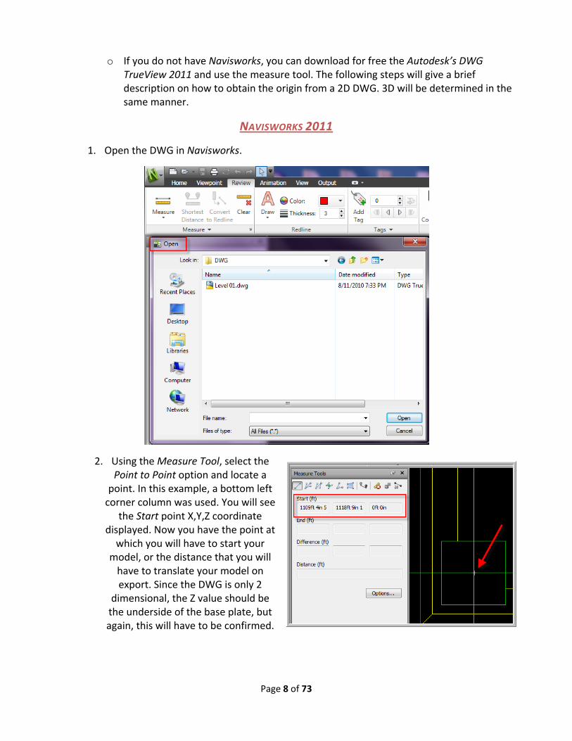
Rotation: ‐ this is one loaded option that can make or break a good export. I will attempt to be as detailed as possible. I will begin with a snapshot of the plan view of the model in SDS/2 so we can get the orientation. In SDS/2, the Global coordinate system is set to Z axis up and Y axis to the north and X axis to the east.
When the Rotate model option is checked, the X‐Y‐Z and Angle fields and buttons become active.
o Chances are you will never have to use the input fields, but they have been made available. For more information on the quaternion coordinate system, search the web.

Page 19 of 73
o The Y up, Y up 180 and Z up buttons will automatically set the correct values for the X‐Y‐Z and Angle fields.
With Rotate model checked and the Y up button selected, the X‐Y‐Z and Angle fields will be populated with values that will cause the outputted coordinate system to be rotated. Instead of the Z axis being up, the Y axis is up. When the VRML file is read into a VRML reader such as BS Contact® by Bitmanagement www.bitmanagement.de/, the model will be imported correctly. Looking down will be correct, the Y axis is up and the Z axis is to the north.
o But when that same file is opened in Navisworks, and it is the first model opened, the model is rotated 180 degrees. The Y axis is up and the Z axis is to the south, as seen in

Page 20 of 73
the HUD (Heads Up Display) in the following picture. This will force the BIM coordinator to have to rotate the model around the Y axis.
o The BIM coordinator will have to select the entire model in Navisworks and right‐click on the model or Selection tree and open the File Units and Transform… option. Then set the Rotation to 180 degrees and type 1 into the Y axis field.
Notice that the Units will be Meters. Do not change this, or your scale will change. Even though the model is set to meters, the Display Units are set to Feet and Inches Fractions, so all the measurements in the model will be correct and shown in Feet and Inches Fractions.
In this next example, the Rotate model is checked and the Y up 180 button selected, the X‐Y‐Z and Angle fields will be
HUD icon
Navigation CUBE

Page 21 of 73
populated with values that will cause the outputted coordinate system to be rotated. Instead of the Z axis being up, the Y axis is up the same as before, but the model will also be rotated 180 degrees. Notice the preset values used.
This option only exists in version 7.218 and up.
o Now the model will have the Top view and model rotation correct in Navisworks, but any VRML viewers will have an incorrect rotation.
o At this point, it must be noted that not only is the VRML the first model being imported into Navisworks, but the coordinate system is set to have the Y axis up and the Z axis south. This will mean that the next model that is appended to the Navisworks scene, will be rotated if the coordinate system does not match. This will likely be the case.
There may be cases, as mentioned earlier, where a DWG, DXF, DWF and DWFX model created by a different discipline may have the coordinate system match the VRML.
It is possible after the VRML model is opened in Navisworks, that the coordinate system can be manually overridden by accessing the File Options – Orientation tab. By performing this operation, the model in this example will require to be rotated.
o In the following picture, we can see what happens when an IFC file export of the model, which has the Z axis up and the Y axis north, is appended.
In Navisworks, the imported IFC model will be white. The model colors are exported with the file as we will see with the Solibri Model Checker® product.
In Navisworks 2011, there is an issue with extraneous polygons being created. This occurs with both SDS/2® and Tekla® IFC imports. This issue did not appear in version 2010 or in the Solibri Model Checker® product.
The following describes what happened when the IFC was appended. The Y axis was set up and the Z axis set to south by the VRML file. When the IFC file with its Z axis up and Y axis to the north was appended, Navisworks lined up the IFC file’s coordinate system with the previously set VRML coordinate system, thus causing the model to be rotated around the X axis.

Page 22 of 73
The black circle is the Insertion Point cone at (0, 0, 0). Lighting has caused it to look black.
With Rotate model checked and the Z up button selected, the X‐Y‐Z and Angle fields will be populated with values that will cause the outputted coordinate system to be the same as the SDS/2 coordinate system. This means the Z axis is up and the Y axis is north. Meaning the Top or plan of the model will be towards the Z axis direction.
This option only exists in version 7.218 and up.
o You will get the same results if you remove the check from the Rotate model option.
o To obtain the same result in versions prior to 7.218, simply remove the check from the Rotate model option. The only reason for the addition of the Z up option is if the user wants the ability to modify the coordinate values.
o On the following picture, we can see that the model is rotated with the top or plan view of the model oriented towards the Z axis direction.
First off, this is the first file opened in Navisworks, which is a VRML file. During the importation, the VRML’s wrl extension is read, and Navisworks sets the coordinate system accordingly to have the Y axis up and the Z axis south. This is performed first, before importing the model information. As mentioned earlier, the VRML file does not contain the information to set the coordinates. The exported model was created with the Z axis up and the Y axis to the north. During the import of the VRML model, the coordinates are aligned accordingly with the top or plan view of the model being in the Z axis direction. We now

Page 23 of 73
see the back of the model in the Y axis direction. Review the HUD in the following picture to get oriented.
o Now if the BIM coordinator were to first import the VRML model into Navisworks, as in the previous example, and they wanted to modify the coordinates to have the Z axis up and the Y axis north for the next model, all they would have to do is adjust the values in the Orientation tab in File Options to have the Z axis up and the Y axis to the north as depicted in the following picture.
Type a 1 into the field that you want to activate.
o Once the coordinate orientations are set the model will now have the top or plan view up towards the Z direction, and the scene will appear correctly. The next model appended with coordinates having the Z axis up and the Y axis north will match the scene’s orientation. Whether the models line up will depend on the origin points, which was discussed earlier, but the rotation will match at the very least.

Page 24 of 73
The following picture shows the result of resetting the orientation from the previous example, and an appended IFC model, which has an orientation of Z axis up and Y axis north. As you can see, the result is that both models are positioned precisely on top of each other.

Page 25 of 73
Before you begin to think that this is a lot of trouble, remember that these issues are not particular only to VRML, and from comments I have heard, the same issues will sometimes occur when importing the DXF, DWG, DWF and DWFX formats.
Now that we have gone through the exporting options for VRML, emphasizing the rotation options, there are a few more points that I would like to make concerning rotation.
I mentioned earlier the necessity of knowing which model is imported first into Navisworks. This is because generally the Architects model is imported first, and in most cases the models coordinate system is set to Z axis up and Y axis to the north. If this is the case, you will want to be sure to export the VRML model with the Rotate model option unchecked.
So what if you do not know which model is being imported first, or the BIM coordinator wants to import your VRML steel model first? To avoid the issue of having all the following models

Page 26 of 73
rotated due to Navisworks setting the Y axis up and the Z axis south due to the VRML, you can export a CIS/2 or an IFC file first to set the coordinate system and then export the VRML with the Rotate model option unchecked.
o In the following example, I created an insertion point material that is set to existing. This is a pointed assembly that can be inserted from project to project, indicating the (0, 0, 0) origin.
o When the BIM coordinator imports the CIS/2 file, the HUD is set Z axis up, and when the VRML model, that was created with the Rotate model option unchecked, is imported, the Top will be the plan view and the rotation of the model will be correct.
o It is important that the CIS/2 imported model is not deleted. If this is done, the VRML model will cause the coordinate system to rotate to the VRML positioning, unless the Navisworks file was saved as a NWF or NWD, or if another imported file in the scene matches the CIS/2’s coordinate system.

Page 27 of 73
o If you have AutoCAD, you can create a drawing with grids that can be imported into Navisworks, which will give the origin, set the coordinate system and give the grids.
Status colors can be exported with the VRML file.
o Status the members in the SDS/2 model, then select the model.
o Export from Modeling the VRML file from either ModeLINK or VRML from Model option.
o In the VRML Properties screen, make sure that Model color is checked.

Page 28 of 73
o The colors can then be seen in Navisworks.
DXF/DWG
Both the DXF and DWG from SDS/2 are nothing more than 3D objects, with shipping marks and layer attributes.
For DXF export versions prior to 7.220 and the DXF (legacy) export in 7.220, the shipping marks are not item names, but are layers. Therefore each member will be on its own layer.
o In the picture on the side we can see from the Navisworks Selection Tree the piecemarks contained in the Layer.
o This would cause thousands of layers to be created.

Page 29 of 73
o In version 7.220 and up, both the DXF and new DWG export will place the piecemarks in the Name branch and the Layers will contain the item types and the zone and/or sequence if the zone and sequence options are checked.
In the following picture below taken from Navisworks of a section cut through a wide flange beam, we can see that the object consists of only faces. The inside is hollow. This means that the object, such as this wide flange, when selected in Autodesk’s MEP products will be built up of individual faces for the flange and web. This would make it tedious to hide the entire material in Autodesk’s MEP products and cause duplicate clashes on material during clash checking.
For DXF and DWG in versions 7.220 and up, the faces have been grouped together in a block for material, or if selected, all the material in the member. This way the entire material or member can be selected in products like DWG True View 2011 or Autodesk’s MEP products. This is the major difference between DXF export in versions prior to 7.220 and DXF export in version 7.220 and up.
In version 7.220, a DXF (Legacy) export has been added which mimics the DXF exports prior to 7.220.

Page 30 of 73
In versions prior to 7.220, DXF does not have the option to translate or rotate the model on export, but it does have the option to export bolts, holes or welds. Version 7.220 has added the model color, surface finish, “By material” or “By member”, layer by zone and sequence, translation and rotation options.
DWG export will only be available to the public with the 7.220 release, therefore to create a DWG a DXF to DWG converter will be required in prior releases.
o DWG has the options to export bolts, holes or welds, model color, surface finish, By material or member, layer by zone and sequence, translation and rotation options.
Some pro’s about importing the DWG or DXF
o An accurate representation of the model, including curves, spiral offsets, angle of twists, bends, copes, cut layouts, preparations and model color.
o Can be imported into AutoCad MEP, or AutoDesk Revit MEP or Autocad.
Autodesk is the predominate product used concerning MEP, to my knowledge.
Import and Export of DXF and DWG (v7.220)
For both the DXF and the DWG, the coordinate system will be set to Z axis up and Y axis to the north.
Let’s get familiar with the DWG/DXF Properties screen for version 7.220 and up.

Page 31 of 73
o The Export of bolts, holes and welds is pretty self evident, and is mentioned previously in the documentation.
o Output material color also is the same as all the exports, so no further description is required.
o For Translation and Rotate CCW about Z axis, refer to the following IFC section.
o Layer options will allow you to add to the created layer names, the zone or the sequence or both.
In the Item ‐ Name, you will see numbers after the piecemarks, these are not zone and sequence, but are unique identifiers.
o Finally, the Export DWG/DXF entities is where you will set whether the faces for the entities are blocked (grouped) either only by material, or by the member. See the following pictures generated from Navisworks 2011.
In the above picture, all the faces for the main material on the member are selected.
In the above picture, all the faces of all the material on the member are grouped together. You will also notice that the individual material can also be selected. This is great for easy selection of gusset plates for mechanical and piping clashes.
By default Navisworks set the units for the DXF or DWG to be imported as millimeters. This default can be changed in the Global Options – File Readers – DWG/DXF. See the picture on the follow page to view the Navisworks Options Editor.

Page 32 of 73
o This unit setting has caused issues when appending VRML, IFC and CIS/2 files. One of the first questions I would ask when I receive a call that the SDS/2 file’s scale is incorrect from the BIM coordinator is; what are the file formats that are being imported into Navisworks?
o With Navisworks, each imported model will have their own File Units. This means that one model can have millimeters, and one appended model can be in inches, and the next appended model in meters.
The following examples will demonstrate the previously mentioned issue concerning importing DWG and DXF in conjunction with an IFC. The example uses a DXF, but the result is the same for DWG. The model in SDS/2 is in imperial units. (Foot‐inch‐fraction)
o This first picture shows an imported DXF into Navisworks which is using all the out of the box settings. File units are millimeters and the display units for measure are Feet and Inches Fractions.

Page 33 of 73
When the model’s units are changed to Inches in the File Units and Transform, and the dimension is taken, it is the correct value of 3’‐2”, as seen in the following picture.
The next operation will demonstrate what often happens when DXF/DWG files are imported first into the Navisworks, and then the IFC file is appended.
o The DXF units were set back to the default millimeters before the IFC was imported.
We can see in the picture the colored primary DXF model which appears about the size of the base plate on the appended IFC model.

Page 34 of 73
When the beam to beam dimension is taken, we can see that the IFC model gives the correct 3’‐2” dimension.
To complete this demonstration, the imported DXF file units will be changed to Inches, which will cause the two models to be lined up.

Page 35 of 73
IFC
The IFC file is a very suitable file format used in the BIM coordination world, due to its ability to contain not only 3D objects, but also a surplus of information about the objects. It also can contain objects from “bed knobs to broom sticks”, where CIS/2 is strictly for structural steel. Though currently the IFC format may not be as structured and deep as its counterpart CIS/2, for the BIM coordination world, the information it contains is sufficient for 3D, 4D and 5D.
o Pros
Accurate representation of the model, including curves, spiral offsets, angle of twists, bends, copes, cut layouts and preparations.
Options to add bolts, holes and welds.
Origin translation capability in version 7.218 and up.
Model rotation option on export.
Contains information such as piecemarks, material, material type, member type, and grade to name a few.
Zone, Sequence and Status information exported in version 7.218 and up, and will display in the Navisworks Selection Tree.
File size is smaller than DWG/DXF. See VRML section for file size comparison.
Can be imported into REVIT.
Coordinate system is Z axis up and Y axis to the north.
o Cons:
Model colors are not read correctly into Navisworks, but are correct into Solibri Model Checker.
Navisworks 2011 currently can have extraneous polygons created.
This occurred with both the SDS/2 and Tekla IFC samples tested.
Must purchase the ModeLINK module.
o Aside from the purchasing of ModeLINK, the cons are out of Design Data’s control.

Page 36 of 73
Import and Export of IFC
The IFC file’s base units are Meter, the same as VRML. When a project in SDS/2 is done in imperial, all the dimensions are internally converted in the export to meters. This is why, as you will see, the File Units in Navisworks will be set to Meters, but when a measurement is performed, the dimension will be accurate.
Let’s begin by getting familiar with the ModeLINK and the IFC Properties export screen from SDS/2.
o As in all exports from Modeling in version 7.2, you can export from selection.
Be sure to use Status to remove any items such as existing members, or dummy members used to generate connections.
After selecting the members from the model, run the ModeLINK command.
o Expand the Export file format: drop down list and select IFC2x3.
o The Change button will allow you to set the destination for the created file and the Output file name: will be the file’s name.
The Properties button launches the IFC Properties screen.

Page 37 of 73
o The export welds, holes, and bolts options are the same as with VRML and DXF/DWG.
Checking any of these options will cause the file size to become larger.
Unless the model is for presentation purposes, these can remain unselected.
For presentations, you really only need to select the bolts, since the holes are most likely covered by the bolts, so why add them. If holes are used for penetrations, you will want to add the holes.
You may want to discuss this with your BIM coordinator.
o Origin Translation: have to be input in decimal inch. i.e. 15’‐5 1/2” => 185.5 in versions 7.219 and below. (In version 7.220 and up, foot‐inch values can be input.)
Unlike VRML, the values DO NOT have to be converted to meter, even though the base units for the IFC fie format are in meters.
o Rotate CCW about Z axis will cause the model to be rotated by the input degree in a Counter Clockwise Rotation.
The picture below shows the results of the IFC export using the settings in the previously shown IFC Properties screen.
o This model was not only translated to the (0, 0, 0) location, but was also rotated 45 degrees counter clock wise.

Page 38 of 73
Concerning the Rotate CCW about Z axis: When the model is to be translated and rotated, a little math needs to be applied to the values. Using the previously shown IFC Properties screen as an example, I will cover the little math required to rotate the model and translate the model to the (0, 0, 0) origin position.
o What occurs during the export is the rotation value is applied first, rotating the model around the Z axis at the current (0, 0, 0) origin point location. The model will then be translated.
o First establish a point in the model. In this case the bottom left underside of the column base plate, which happens to be (103’‐0, 0, 85’‐5).
o Multiply the inverse cosine of 45° by 103’‐0, which will return a value of 72’‐10”. Since this is 45° the bases and rise will be the same value.
o This will mean that after rotation, the model will have to be translated (‐72’‐10, ‐72’‐10, ‐85’‐5) to position the column of the rotated model at the (0, 0, 0) origin point.
As mentioned earlier, in version 7.218 and up, a portion of the Member Status Review screen from SDS/2’s Member Edit will be automatically exported within the IFC file, as well as the Zone and Sequences.
o By exporting the status, zone and sequence information in the IFC file, the BIM coordinator will be able to hide or color code the model for presentations.
o Fields within the General group and the Member routes are not exported.
Future releases may contain Custom Properties, Model Revisions, Categories and Routings, depending on demand.
45°

Page 39 of 73
In the picture above you can see the color coded status settings in the SDS/2 model.
In the picture below we can see an example from Navisworks of an IFC file which has been imported from SDS/2 with the status, zone and sequence in the IFCPROPERTYSET.

Page 40 of 73
The following pictures demonstrate more of the data that is available by using an IFC file for import into Navisworks.
By no means, do the screen shots above encompass all the available information from an IFC import, but they do show the data benefit of using IFC over VRML, DXF and DWG.

Page 41 of 73
CIS/2
CIS/2 is a very data rich file format which functions very well in the manufacturing side of the industry. Where IFC is very wide with the data it contains, CIS/2 is very deep and well structured. When it comes to the BIM coordinator, CIS/2 currently contains more information than required at this time.
o Pros
Contains more data about the structural steel for engineering and manufacturing.
o Cons:
Curved members, end preparations, cut layout operations, bends, tension control bolts, status information and web penetrations will not import into Navisworks or will import incorrectly.
Below is an example of the sample SDS/2 model imported into Navisworks. We can immediately see that none of the curves have come across, nor the web penetration.

Page 42 of 73
Not to discourage the use of the CIS/2 file format, but when it comes to Navisworks, currently there are better file options for importation. Plus, CIS/2 can only be imported into Navisworks versions 2010 and up.
Concerning the SteelVis translator (cic.nist.gov) which imports a CIS/2 file and converts it to a VRML or IFC file format, you will still have issues with the curves. Below is an example of the CIS/2 file translated to a VRML and imported into Navisworks 2011.
Again, just because CIS/2 does not function well into Navisworks, by no means excludes it from the BIM world. When it comes to the transfer of information to and from engineering packages, the CIS/2 file format contains more of the required data, which IFC currently lacks.
CIS/2 is also used to operate robotic cutting and welding machines through the StruCIM® program.

Page 43 of 73
Export of CIS/2 from SDS/2
CIS/2 files are exported through ModeLINK.
With CIS/2, the members to be exported can either be sent from model selection, or from a selection list.
The CIS/2 Export screen offers many options for data and drawing export, but for the export for Navisworks, the default settings will suffice.
The coordinate system for the CIS/2 file matches the IFC with the Z axis up and the Y axis towards the north.

Page 44 of 73
A final note of caution before we move onto more Navisworks specific information. The translation and rotation fields in the various file export formats from SDS/2 will carry the input values from one screen to the next. Therefore it would be prudent to verify the input values in the screen before the export is executed.
Exporting DWF/DWFX from Navisworks for import into SDS/2
DWF/DWFX files can be exported from Navisworks which can then be imported into SDS/2. This can be useful for clash detection in SDS/2 when developing connections, especially where gusset plates are concerned. Take for example a project where the BIM coordinator using Navisworks has a complicated architectural finishing on a structure and the detailer wants to check to see if any of the steel penetrates the finish. The detailer can request the BIM coordinator to export a DWF for clash detection.
One drawback to the previously mentioned scenario, is that the file type imported into Navisworks may affect the DWF export from Navisworks.
o The following file formats imported into Navisworks that will cause the material in the exported DWF to be incorrectly positioned in SDS/2 are as follows; IFC, CIS/2 and RVT files. VRML, DWG, DXF and some DWF files used as the base imported files into Navisworks will create DWF files where the material will be positioned in SDS/2 correctly.
Objects hidden in Navisworks will not be exported in the DWF.
Navisworks file formats
Before covering file formats, we need to know the Navisworks products that are available. The Navisworks suite are as follow;
o Navisworks Manage 2011, which replaces Navisworks Review 2010.
This product allows complete review, clash detection, animations, presentations and time lining of multiple models appended using multiple file types.
Ability to import a CIS/2 file. Please review the previous section on CIS/2 files into Navisworks.
From my findings, this is the product that is predominately being used in the market for BIM collaboration. Especially used by BIM coordinators with general contractors and consulting firms.
o Navisworks Simulate
As the title indicates, this product will allow you to simulate procedures such as site construction and scheduling.

Page 45 of 73
o Navisworks Freedom
This product is a free review tool that allows the users to review the collaborative models 4D simulations, and review the 3D elements information.
This product is used primarily for collaborative meetings
Only NWD and DWF/DWFX files can be read into Navisworks Freedom.
o Autodesk Design Review – This is not titled as a Navisworks product, but it is in the Navisworks web site.
Autodesk Design Review is also a free viewer with mark up capabilities.
3D DWF files can be imported. Dimensions and comments can be added to the 3D model.
o This document will focus on Navisworks Manage 2011.
There are three native file formats that can be saved from Navisworks, NWD, NWF and NWC. Instead of reinventing the wheel, I will cite the description of theses file formats directly from the Navisworks 2011 Help menu.
o “By default, when you open or append any native CAD or laser scan files in Autodesk Navisworks, a cache file is created in the same directory and with the same name as the original file, but with an .nwc file extension. NWC files are smaller than the original files, and speed up your access to commonly used files. When you next open file or append file in Autodesk Navisworks, the data is read from the corresponding cache file if it is newer than the original file. If the cache file is older, which means the original file has changed, Autodesk Navisworks converts the updated file, and creates a new cache file for it.”
Any Transforms, Appearances or Links done in Navisworks will be lost if this file format is sent to the client.
o “An NWF file contains links to the original native files (as listed on the Selection Tree) together with Navisworks‐specific data, such as review markups. No model geometry is saved with this file format; this makes an NWF considerably smaller in size than an NWD.”
Any Transforms, Appearances, Markups or Links will be maintained if this file format is sent to the client.
Be sure to send all the source (native) files associated with the NWF, or a prompt to resolve the issues will appear.

Page 46 of 73
A major advantage of using the NWF file format is when changes are made in the original model. If the name of the imported file remains the same or is resolved, all the Transforms, Appearances, Markups or Links will be maintained, and the model information will be updated when the updated native file is imported.
In the examples below, the IFC file named NavisTrainSection.ifc is imported into the NavisTrainSection.nwf. The orange members, indicate the erected members.
In the first picture, we can see that the beam between the front two columns is not orange indicating that it does not have an erected status.
In the second picture, the NWF fie was opened and using the resolve option, an updated IFC file named NavisTrainSectionRevised.ifc was selected for the native file. The beam between the front columns is now orange, indicating that it is set as erected. You will notice that the colors for the beam members that were set from a prior operation are maintained. As stated earlier, all the Transforms, Appearances, Markups or Links will be maintained.
If a member is moved in the originating model, the updated IFC file will cause the Transforms, Appearances, Markups or Links on that member to be lost. In our example, a beam was moved on the floor. In the updated model, the overridden color operation of that beam was lost and the beam changed to the default white.
First Picture Second Picture

Page 47 of 73
o “An NWD file contains all model geometry together with Navisworks‐specific data, such as review markups. You can think of an NWD file as a snapshot of the current state of the model. NWD files are very small, as they compress the CAD data by up to 80% of the original size”.
This file format can be opened in Navisworks Freedom.
This file format does not require the sending the cache or native files.
Model locations and rotations are maintained.
Any settings such as colors or hidden objects are maintained.
Objects can be moved or transformed, but if two models were joined together, a rotation will cause both models to be rotated.
If two or more models are saved when creating the NWD, the Units are merged as one.
For example a DWG that is in inches and a VRML which is in meters, if the file is saved as a NWD, the units will be set to the units of the primary model. This does not affect the model scaling.
Navisworks Commands 2011
Since this document is not a training manual on Navisworks, only a few useful tips will be listed concerning file importation and manipulation.
Previously in the document, File Units and Transform and File Options have already been discussed.
To set the coordinate system as a visible icon, select from the View ribbon the HUD (Heads Up Display) icon and check the XYZ Axes.
When selecting an item from the scene in the model to view in the Properties screen;
o From the Home ribbon in the Display group, select the icon.
o While hovering over and item in the model, right‐click and set the Set Selection Resolution To Last Object. (This is just my preference)

Page 48 of 73
o Select the item. In this case a beam was selected.
o While holding down the <SHIFT> key, select the same item. Not only will the information change in the properties screen, but what is selected will change.
o As we continue to hold <SHIFT> and select, eventually you will come to a properties screen that contains an IFCPROPERTYSET tab. One IFCPROPERTYSET tab will contain the general information about the item and the other will contain the status settings.

Page 49 of 73
o As you press <SHIFT> the properties shown are from the selection tree.
o Note that the imported file type used will affect which properties are available for viewing.
Objects in the model can also be selected using the Selection Tree. To open this screen, select
the icon from the Home ribbon. This will allow you to expand and collapse the file tree.
o At the bottom of the selection tree you will find at least three buttons, Standard, Compact, Properties and possibly a fourth, Sets. The following descriptions were taken directly from the Navisworks 2011 Help.
“Standard ‐ Displays the default tree hierarchy, including all instancing. The contents of this tab can be sorted alphabetically.”
“Compact ‐ Displays a simplified version of the hierarchy on the Standard tab, omitting various items. You can customize the level of complexity of this tree in the Options Editor.”
“Properties ‐ Displays the hierarchy based on the items' properties. This enables simple manual searching of the model by item property.”
“Sets - Displays a list of selection and search sets. If no selection and search sets have been created, this tab is not shown. Note: The list of the items on the Sets tab is exactly the same as the list on the Sets dockable window.”
From the Selection Tree, more than just selecting items can be preformed. The two hierarchies that will be focused upon will be the IFC and IFCPROPERTYSET. These two trees will contain the information that coordinators are generally looking for.

Page 50 of 73
o Note that these two hierarchies will only be created if the imported file was an IFC.
o When a right‐click is performed while hovering over an item in the Selection Tree, a number of other options are exposed.
o When Scene is expanded, you are able to execute View All which is a quick way to view the entire model. Especially when you are zoomed into a Scene and you want to zoom to the extents of the model quickly.
o Pressing <CTRL> or <SHIFT> will cause selection to function in the typical windows fashion.
o By selecting the Override Item ‐> Override Color command, you can change the color of the objects in the model.
For example, BEAM can be selected from the Selection Tree, which will select all the beams in the model. Then using Override Color, set the RGB values 160, 96 and 80 from SDS/2 beam for the colors used in Navisworks and now the IFC file members color will match SDS/2.

Page 51 of 73
The same procedure can be applied for the sequences or status’ found in the IFCPROPERTYSET.
To change your model from perspective to orthographic, right‐click while hovering over the Navigation CUBE and select Orthographic. This will make it easier to view the model, especially for the SDS/2 users.
Perspective view Orthographic view
Page 52 of 73
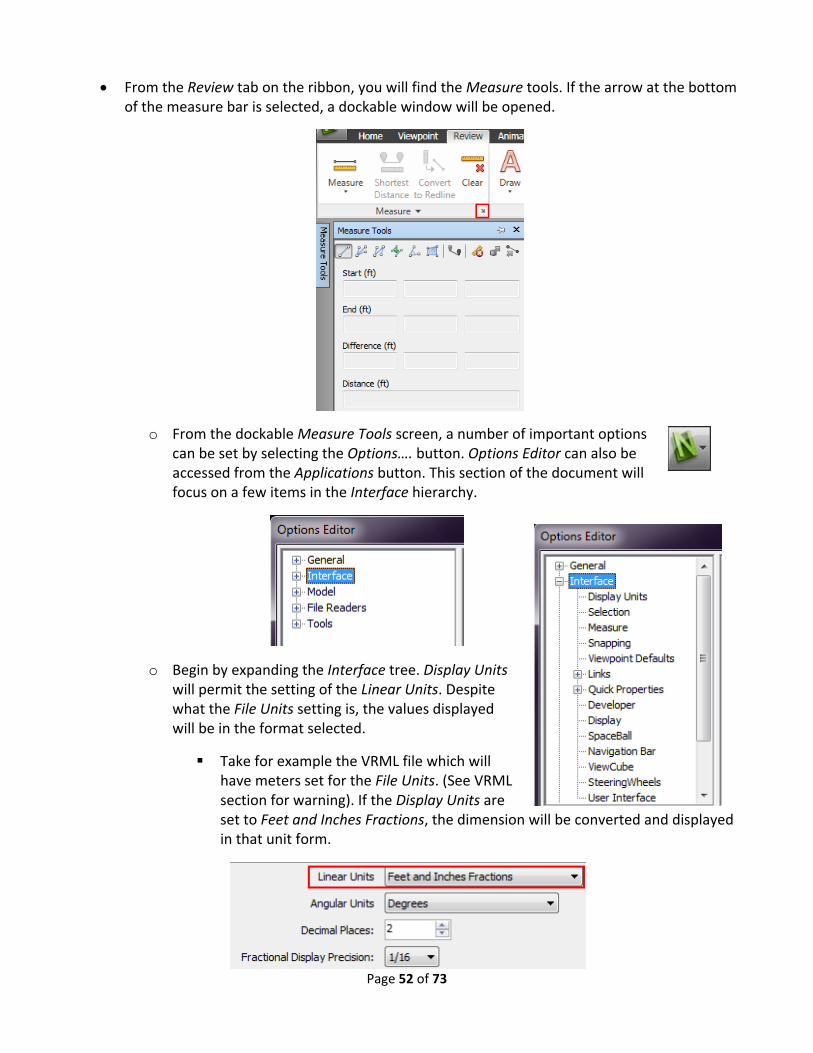
From the Review tab on the ribbon, you will find the Measure tools. If the arrow at the bottom of the measure bar is selected, a dockable window will be opened.
o From the dockable Measure Tools screen, a number of important options can be set by selecting the Options…. button. Options Editor can also be accessed from the Applications button. This section of the document will focus on a few items in the Interface hierarchy.
o Begin by expanding the Interface tree. Display Units will permit the setting of the Linear Units. Despite what the File Units setting is, the values displayed will be in the format selected.
Take for example the VRML file which will have meters set for the File Units. (See VRML section for warning). If the Display Units are set to Feet and Inches Fractions, the dimension will be converted and displayed in that unit form.

Page 53 of 73
Snapping is where the various snapping options are located. You can see that my preference is to select all the options.
o Back in the Measure Tools window. The Point to Point button will allow you to take a dimension from one selected point to the next. This will populate the coordinate values.
Like SDS/2, the values can be copied by highlighting the value and selecting <CTRL> ‐ C.
The Clear button will clear any added dimensions.
o If two objects are selected, the Measure Shortest Distance will measure the shortest distance between the two objects.
To select more than one object in Navisworks, press and hold the <CTRL> key during selection.
To clear all selected objects, press <ESC>.
o If an object, or an entire model in the scene is selected, and the Transform Objects button is selected, the selected object will be moved to the End point location. This will be demonstrated in the following Transform bulleted point list.

Page 54 of 73
To easily select an entire model, in the Selection Tree, select the Compact tab and select the model.
Transform or model relocation can be handled in several ways. To continue on from the previously bulleted point, the Transform Measure Tool will be discussed first.
o As stated previously, first select the object or objects to be moved or transformed.
o Then select the Point to Point button, and select the Start and End point
o Then select the Transform Objects icon and the object will be moved or transformed from the Start selected point to the End selected point.
Pressing <CTRL> ‐ Z will undo the operation.
o In Navisworks 2011, the other method to transform is to select the Item Tools tab in the ribbon, which appears when an object is selected.
o If the Move Gizmo is selected, you are able to freely move the selected object by grabbing the Gizmo handles or grabbing along the Gizmo lines and then sliding the object.
o More precise movement can be achieved by expanding the Transform drop down list below the Move Gizmo. This will expose the manual entry fields. The following points will discuss on how to use this tool. Move Gizmo

Page 55 of 73
With the object or objects selected, select the Item Tools tab, select the Move Gizmo button and expand the Transform drop down.
From our previous measured Start point, we can see that its X, Y, Z location is
at . This is the point of the wedge.
Next we will move the Transform Center to the point of the wedge.

Page 56 of 73
Using the Difference from our previous measurement, we will transfer the position of the wedge to the location that was used with the Transform Objects tool.
Both the Rotate Gizmo and the Scale Gizmo function in the same manner as the Move Gizmo.
o Models can also be transformed using the File Units and Transform screen.
You first need to determine the base point that you want to move from and then determine the distance to the final location. For example, the base point indicated in the following picture is located in the X, Y, Z coordinate 103’‐0, 0, 85’‐0.

Page 57 of 73
The desired end point coordinates to translate the model to are 0, 0, 0. This means the values required to translate the model are ‐103’‐0, 0, ‐85’‐0.
From the Selection Tree, select the Compact tab, hover over the model to be translated and right‐click. From the right‐click menu, select File Units and Transform. Type in the Origin(ft): the values 103ft 0in, 0, ‐85ft 5in.
A reminder concerning units and DWG/DXF file formats. A frequent issue is that DWG/DXF Default Decimal Units, located in the Navisworks Options Editor File Readers, is set to a default of millimeters for the units. When a DWG/DXF is imported into Navisworks from an imperial SDS/2 project, the model will appear small and possibly misplaced. To resolve this issue, right‐click on the model in the Selection Tree and change the File Units to Inches. For examples refer to the Import and Export of DXF and DWG (v7.220) portion of this document.
Navisworks has the ability to compare models. Either entire models or individual objects can be compared. To compare objects:
o Select the two objects, this demonstration, two versions of the model are being compared.
o From the Home ribbon, select the Compare on the far right of the ribbon.
o Once the compare is selected the Compare screen will open. For more information on how this screen functions, please refer to the Navisworks Help menu. In this example, Type will be compared for differences and the results will be highlighted.

Page 58 of 73
o The result is that two floor beams are different when the Type is compared. The difference is that the member has been moved to a different location between the two models.

Page 59 of 73
o The color‐coding of the highlighted results by default, taken from Navisworks Help are:
White. Matching items
Red. Items with differences
Yellow. The first item contains things not found in the second item.
Cyan. The second item contains things not found in the first item
o To clear the highlighting, select Reset All.. within the Home tab. Finish by selecting Appearances.
This will conclude the Navisworks portion of the documentation. Though the focus was on Navisworks, all of the file export types were covered in‐depth, except for the CIS/2 file format.
The remaining information in the documentation is only brief descriptions, which will be fleshed out in the second issue of the documentation. The second issue will also continue from where this document has left off.
Solibri Model Checker v6®
Solibri will import an IFC and a DWG file. Solibri is still being researched and will be completed further in Issue 2 of the document.
No information can currently be exported from Solibri into SDS/2.
SDS/2 model colors come across with the import of the IFC file, and the file information is also well organized, for example the IFCPROPERTYSET (Pset_SDS2_General) seen in the picture below.
Since the Status information from SDS/2 is attached to the member and not the main material, when an object is selected that contains only a main material with no submaterials,

Page 60 of 73
(Discrete Accessory) the Pset_SDS2_Status tab will appear in the Information screen displaying all the SDS/2 Status settings.
To access the Pset_SDS2_Status information on members that contain submaterial, select the member in the model, in the Information screen, select the Relations tab, expand Decomposes and then double‐click on the Object….. hyperlink. The Pset_SDS2_Status tab will appear.
Using the Information Takeoff many tools can be created to query the model. In the following pictorial example, an approval status search was created.

Page 61 of 73
Solibri has the ability to append multiple models.
To rotate and move models, from the Model tab, select the model in the Model Tree and then right‐click and select the Move or Rotate command.
It is very import to accurately select the correct discipline for the model at the beginning of the project.

Page 62 of 73
Autodesk Revit Structures® v 2011
For Revit, currently the best import file option to use is an IFC file.
o If the IFC file is translated or rotated on export from SDS/2, the model will be imported incorrectly into Revit. It is better to translate the model in Revit.
A CIS/2 file import will cause all the submaterial on the members to be placed at the left end.
o CIS/2 import requires a plug‐in to import and export.
DWG files can be linked into Revit.
o Using Revit 2011, from the ribbon select the Insert tab.
o Select the Import CAD button. From the Import CAD Formats screen, select the DWG file.
o After the import is complete you will receive a warning box.
o From the Project Browser, double click on the 3D Views – View 1 – Analytical.
o If members are missing from the view, from the View tab, select the Visibility/Graphics button. Select all of the items in the list.
o From the View Control Bar at the bottom of the drawings, you can set
the model to the desired shading style.

Page 63 of 73
o The model will be one block, but it still can be used as a reference model.
o DXF imports directly into Revit.
Just objects, no intelligence
DXF is a very large file.
With the IFC import the same information mentioned previously concerning visibility and shading are applied.
Revit will also allow properties and status information to be displayed with an IFC file import.
o The same issues in Solibri concerning the status information also apply to Revit. Members contain the status information, so the member properties, not the material properties, must be displayed to view the status.
o To view the Type Properties, select the member and then within the Modify tab select the Type Properties button.
o Presently I am not aware of a method to select the member in Revit. If a way is discovered, it will be added to the Issue 2 of the document. There currently is a priority request to show the member status on each main material object to eliminate this issue.
Wire Shaded

Page 64 of 73
Bentley Structures©
Bentley structural can import both the IFC and the CIS/2 file format from SDS/2.
An advantage of using Bentley Structural is the ability to analyze the structure with RAM or STAAD.
Depending on the release, STAAD may or may not import into SDS/2 using a CIS/2 file.
o Latest release (current as of 09, 2010) will not import into SDS/2.
o Design model or analysis models with assembly mapping are to be used.
o It is possible to transfer the model to SDS/2 by using Bentley Structures as an intermediary or go‐between.
The ISM format developed by Bentley will help support model transfer between RAM, STAAD, Bentley Structural and SDS/2.
Status Properties of member containing only main material
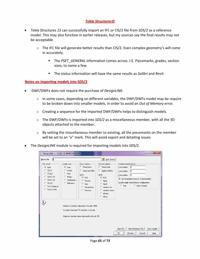
Page 65 of 73
Tekla Structures©
Tekla Structures 15 can successfully import an IFC or CIS/2 file from SDS/2 as a reference model. This may also function in earlier releases, but my sources say the final results may not be acceptable.
o The IFC file will generate better results than CIS/2. Even complex geometry’s will come in accurately.
The PSET_GENERAL information comes across. I.E. Piecemarks, grades, section sizes, to name a few.
The status information will have the same results as Solibri and Revit.
Notes on importing models into SDS/2
DWF/DWFx does not require the purchase of DesignLINK.
o In some cases, depending on different variables, the DWF/DWFx model may be require to be broken down into smaller models, in order to avoid an Out of Memory error.
o Creating a sequence for the imported DWF/DWFx helps to distinguish models.
o The DWF/DWFx is imported into SDS/2 as a miscellaneous member, with all the 3D objects attached to the member.
o By setting the miscellaneous member to existing, all the piecemarks on the member will be set to an “e” mark. This will avoid export and detailing issues.
The DesignLINK module is required for importing models into SDS/2.

Page 66 of 73
o Contact [email protected] for information on purchasing the module.
CIS/2 consists of three types of models.
o Analysis
A 3D model that contains member sizes and geometric locations. The physical locations of the steel elements and nodes
o Design
A 3D model that contains member sizes, loads and locations of steel elements.
The design model will contain assembly mapping. This will cause elements to be mapped together. For example, columns on a two story building will be mapped together as one column, instead of the column be broken to two, one column from the ground to first floor and another from the first to second floor.
An analysis model can also contain assembly mapping.
o Manufacturing (Detailing)
A 3D model that contains the structural members, their connections and secondary members.
o The Create member only option in the CIS/2 import will cause the system to import only the member’s main material.
IFC import has the option to import the model items as native SDS/2 objects, or as a reference model which will be imported in the same fashion as the DWF/DWFx model.
o With the IFC import, the following options are available.
With the Prompt for unrecognized materials checked, materials that are not in the SDS/2 material file will have a replacement requested. Once a replacement

Page 67 of 73
is selected, all the materials with the same designation will use the replacement.
Since items, such as plates are not in the material file, if a replacement is selected, that will be the material description designated for the section size, but in the model that item will appear in its original imported geometry. Only the description will be replaced and that material type screen will be used.
o My suggestion is to not check this box. If it is checked then you will be prompted to either choose a replacement or make the item miscellaneous. Miscellaneous means Standard Part Material.
Unknown items will become standard parts.
Since the IFC file format currently does not have the working point information, when receiving an IFC model to be used as a base for detailing, it is preferable to request at an early stage to have the members modeled from working point to working point with no setbacks and no connection material.
The picture below is an example of an imported Tekla IFC file.
Taken from Tekla Structures® IFC sample file

Page 68 of 73
The following bulleted list will demonstrate how to use the imported Sample_Tekla Structures IFC model. This model has connections. The IFC members are converted in SDS/2 from the main material start point to end point. The model was imported into SDS/2 v7.220 using the following settings for the first import of the model. Note the Prompt for unrecognized materials is not checked, the model is imported as a reference model, the sequence is assigned as Import and the Default member Status is set to existing.
o This model was only imported as a reference to show comparisons. When the mouse is hovered, you can see that all the materials are attached to the same miscellaneous member.
By setting the reference model to sequence Import, you can use the Status Display to mask and color code the model.
By setting the member as existing, all the submaterial marks will be existing, therefore excluding them from any exports.
o The same IFC was then imported using the following settings:
o Even though the model has not been processed yet, the members can be set to solid form. See the following picture.

Page 69 of 73
o As we look at the solids, we can see that the model looks fine, but in this case looks can be deceiving. We can see that the stick does not go from member intersecting point to intersecting point.
o When the member is edited, we can see that despite the fact that the member does not connect intersecting point to intersecting point, the member Type, elevation and section size are exported. The connections are locked in graphical and set to Plain End and the main material is User.

Page 70 of 73
o To repair this model, the members would have to be stretched to the intersecting points, the main material would need to be set back to System, the Graphical connection flags cleared and the connection changed from Plain End. The following picture shows some of the members that have had the previous operations performed. The repaired members will have the standard SDS/2 colors.

Page 71 of 73
o In this picture, the beam and horizontal brace were stretched to the column intersecting points, and all graphical material and connections were cleared, and the connections were set to Auto Standard. The column and the beam connecting to the web were left in their imported state.
Concerning the bent plates such as the pour stop and flat plate material. If the material is not prompted to be replaced, both items will become Standard Part Material. If the option to prompt for a replacement material is used, only the bent plate material will have the replacement section. All the flat plate material will still be a Standard Part Material. As mentioned previously, when importing an IFC file, material that is not in the SDS/2 Material File will be unrecognized.
There is no function to change the material type, so if the material is copied to the member its type will remain the same, and therefore remains as such in the Bill of Material.
o Essentially, to repair this model would probably take longer than to input the model from scratch. But having the ability to import the IFC as a reference model is useful for validation and revisions made to the model. As stated previously, if the imported IFC model had the members modeled working point to working point, with no connections, the amount of manipulation would be reduced dramatically.
If possible you may want to have both an IFC and a CIS/2 file to import, where the IFC is imported as a reference model. IFC will give an accurate object representation that can be used to validate the CIS/2 import.
For native member creation from a file, the CIS/2 format is preferred for importing into SDS/2.
o CIS/2 will not currently import curved members.
o The CIS/2 file contains important information such as rotations and member intersecting point to intersecting point, which is not contained in the IFC file format.
There are two tools that are helpful concerning the import of models into SDS/2;
o In Change Options, the Set Vertical Brace Workpoints to 1/2 Nominal Depth of Supporting Beam.
This tool will set all the braces in the job to half nominal depth, as stated. It is important to note that this is an all or nothing operation. If brace points were

Page 72 of 73
manually moved, running this tool would cause the manipulated workpoints to relocate back to half nominal depth of the supporting member.
The members must be processed before this tool can be utilized.
New to 7.2, in the Member drop down, the Change Type tool will allow you to change a member type. Exceptions to this are the following:
o Members that are of a type that cannot be converted, the Warnings window opens. It lists the member number [num] of the members that were not converted and informs you that each of these members are "Not a convertible member type." Member types that cannot be converted are stair, handrail, anchor rod and embed plate.
o If you attempted to convert a perfectly vertical column to, for example, a beam or girt or purlin, the member will not be converted, and you will get the message: "Beams, girts, and purlins must have a plan length >= (1/16 inch or 1 mm)."
o If you attempted to convert a perfectly horizontal member such as a beam to a column, the member will not be converted, and you will get the message: "Columns must be >= (1/16 inch or 1 mm) vertically."
o If you attempted to convert a miscellaneous member that was not a rolled section, the member will not be converted, and you will get the message, "Miscellaneous member does not have a main material from which the section size can be determined." You can also get this message for a miscellaneous member that is a rolled section if the box for "Main member material" is not checked ( ).
o If you attempted to convert a member that had its "Model complete date" set, the member will not be converted, and you will get the message: "Member is marked model complete and cannot change type."
o If you attempted to convert a member that has a frozen piecemark, the member will be converted, but its piecemark will be thawed, and a new system piecemark will be assigned to it. You will get the message, "Piecemark on member has been thawed." If there are other members under the original piecemark, they will not be affected.
Viewers
There are a number of free viewers Available.
o Autodesk® Design Review, as mentioned earlier, is especially useful for marking up 3D DWF files. It can also read DWG, DXF, and many other formats. DGN files can also be imported.
Autodesk® DWG TrueView 2011 also fits into this category.
o For IFC files, Solibri Model Viewer® is my first choice. Other options exist such as DDS‐CAD which also reads a DXF and DWG file format.

Page 73 of 73
o For CIS/2, the SteelVIS will convert the file to a VRML or IFC file format which can be read in available Free viewers.
o For VRML readers there is BS Contact (Bitmanagement Software GmbH®) and MYRIAD® 3D reader which also reads DWF files.
o If you search the web, you will find many other suitable viewers, offering various degrees of functionality.
o Viewers are especially useful when you are having issues with an imported file. On many occasions, by using a viewer I was able to determine if the issues was with SDS/2, or the exported file.
Final Comments
Though this document may seem to be pretty lengthy, it is only a small portion of information concerning BIM. The Implementation of SDS/2 into the workflow and 3D digital review, have yet to be added to this document. There currently is a course held by me covering these two topics, and eventually this information will be added to this document.
Also, from this document, hopefully you can see that SDS/2 is very much part of the BIM world, when it is understood where it fits. It is no less a part of BIM than Autodesk® MEP which is predominately used in the market. It is Design Data’s responsibility to provide the best information for its function in the BIM market.
Concerning detailing firms that use SDS/2, a few issues come to the forefront. Most of the firms that I come in contact with refuse to add information to the model for the other disciplines, or basically refuse to expand their view outside of the steel detailing world. BIM is not going away and it is not just for the “Big Boys”. Currently two states require BIM on projects, Wisconsin and Texas. Wisconsin requires BIM on any public projects over $25 million. Owners are also requiring BIM on their projects, regardless of size or project type. The challenge for the detailing office is how to stay profitable in this new construction industry standard. With these struggles, new opportunities for services are opening up, which will generate revenue for the entrepreneur.
Many steel detailing firms misuse status settings and do not create complete and accurate models. These practices will have to be abandon if they want to play in the BIM world. Custom properties exist and in version 7.2 out of the box properties exist which have parametrics, reports, advanced selection and Status’ created specifically for them. There is no good reason to incorrectly use status settings anymore.
Some suggestions to conclude this document would be first and foremost, educate yourself. The longevity of your business will depend on this. Educate yourself on the most current SDS/2 abilities, on the available industry softwares, on BIM/VDC, or whatever it may be called tomorrow, on current practices in the industry, and business opportunities. Become a student and a promoter, your competition will and probably already does.