image registration of sectioned brains
TRANSCRIPT

International Journal of Computer Vision 73(1), 5–39, 2007
c© 2007 Springer Science + Business Media, LLC. Manufactured in the United States.
DOI: 10.1007/s11263-006-9780-x
Image Registration of Sectioned Brains
OLIVER SCHMITTInstitute of Anatomy, University of Rostock, Gertrudenstr. 9, D-18055 Rostock, Germany
JAN MODERSITZKI, STEFAN HELDMANN AND STEFAN WIRTZInstitute of Mathematics, University of Lubeck, Wallstraße 40, D-23560 Lubeck, Germany
BERND FISCHERInstitute of Mathematics, Medical University of Lubeck, Wallstraße 40, D-23560 Lubeck, Germany
Received December 1, 2004; Revised February 22, 2006; Accepted April 27, 2006
First online version published in September, 2006
Abstract. The physical (microtomy), optical (microscopy), and radiologic (tomography) sectioning of biologicalobjects and their digitization lead to stacks of images. Due to the sectioning process and disturbances, movementof objects during imaging for example, adjacent images of the image stack are not optimally aligned to each other.Such mismatches have to be corrected automatically by suitable registration methods.
Here, a whole brain of a Sprague Dawley rat was serially sectioned and stained followed by digitizing the20 μm thin histologic sections. We describe how to prepare the images for subsequent automatic intensitybased registration. Different registration schemes are presented and their results compared to each other froman anatomical and mathematical perspective. In the first part we concentrate on rigid and affine linear methodsand deal only with linear mismatches of the images. Digitized images of stained histologic sections often ex-hibit inhomogenities of the gray level distribution coming from staining and/or sectioning variations. Therefore,a method is developed that is robust with respect to inhomogenities and artifacts. Furthermore we combinedthis approach by minimizing a suitable distance measure for shear and rotation mismatches of foreground ob-jects after applying the principal axes transform. As a consequence of our investigations, we must emphasize thatthe combination of a robust principal axes based registration in combination with optimizing translation, rota-tion and shearing errors gives rise to the best reconstruction results from the mathematical and anatomical viewpoint.
Because the sectioning process introduces nonlinear deformations to the relative thin histologic sections as well,an elastic registration has to be applied to correct these deformations.
In the second part of the study a detailed description of the advances of an elastic registration after affine linearregistration of the rat brain is given. We found quantitative evidence that affine linear registration is a suitable startingpoint for the alignment of histologic sections but elastic registration must be performed to improve significantly theregistration result. A strategy is presented that enables to register elastically the affine linear preregistered rat brain

6 Schmitt et al.
sections and the first one hundred images of serial histologic sections through both occipital lobes of a humanbrain (6112 images). Additionally, we will describe how a parallel implementation of the elastic registration wasrealized. Finally, the computed force fields have been applied here for the first time to the morphometrized data ofcells determined automatically by an image analytic framework.
Keywords: neuroimaging, human and rat brain serial sections, affine registration, elastic registration, matching,alignment, warping, 3D-reconstruction
1. Introduction
The three dimensional-reconstruction (3D-reconstruction) of images derived from physical(microtomy, serial sawing of plastinated structures),optic (conventional confocal microscopy, laserscanning confocal microscopy), and diagnostic imag-ing (magnet resonance imaging (MRI), functionalmagnetic resonance tomography (fMRI), computertomography (CT)) need to be spatially reconstructedfor the purpose of visualizing the three dimensionalextension of structures. Meanwhile, the 3D-recon-struction and volume visualization delivers importantinformation for preoperative planing in neurosurgery(Desgeorges et al., 1997) and other disciplines(Lamadø et al., 2000).
Since the physical principles of microscopical op-tics have been elaborated (Abbe, 1873) it has be-come customary to slice thick specimens in order toreduce mass thickness and provide translucent ob-jects, for microscopy. The first 3D-reconstruction us-ing serial sectioning and modelling via a wax platetechnique has been published by Born (1883) fol-lowed by an epochmaking 3D-reconstruction of theretina (Sjostrand, 1958). A few years later Glaserand Glaser (1965) demonstrated a computer gen-erated 3D-reconstruction from images derived fromserial sectioning analyzed by a light microscope.Since these striking works many articles dealingwith different kinds of 3D-reconstructions basedon microscopical data (transmission electron micro-scope (Bron et al., 1990; Gremillet et al., 1991),lightmicroscopy of semithin-sections (Schmolke andFleischhauer, 1984; Schmolke, 1996), lightmicroscopyof 5 to 50 μm thick sections have been published(Schormann and Zilles, 1998; Ourselin et al., 2001b).
A disadvantage of sectioning, staining and mountingthe sections on the slides is a lack of spatially perfectmatching when the sections are superimposed. Nev-ertheless, such undesirable mismatching of successivesections must be corrected. Correcting mismatches or
sequential alignment is called registration. Presently,registration of serial sectioned specimens is performedwith digitized objects in terms of images althoughanalog material can be registered as well (Sjostrand,1958). Because serial sectioning is a widely usedtechnique to gain an insight into the three dimen-sional structure of one object or to get an idea ofthe distribution of biological objects (cells, fibers,proteins) in 3D, many anatomists and biologists re-gard it as indispensable. The problem arises as tohow to register. Since there exist different kinds ofregistration techniques (Brown, 1992; van den Elsenet al., 1993; Maintz and Viergever, 1981; Lester andArridge, 1999; Modersitzki, 2004) for different regis-tration problems, in particular for the alignment of im-ages of serial sections, we will concentrate in the firstpart of this contribution on affine linear registration indifference to other—especially nonlinear—techniques(Broit, 1981; Horn and Schunck, 1981; Bajcsy andKovacıc, 1989; Christensen, 1994; Viola and Wells,1993, 1997; Bro-Nielsen and Gramkow, 1996; Thirion,1998; Modersitzki et al., 1999; Schmitt and Eggers,1999; Schmitt et al., 1999) which will be considered indetail in the second part.
Prior studies presenting 3D-reconstructions based onserial sectioning of biological material have one aspectin common: the alignment is done manually (Wareand LoPresti, 1975; Dierker, 1976; Macagno et al.,1976, 1979; Perkins and Green, 1982; Johnson andCapowski, 1983; Street and Mize, 1983; Aferzon et al.,1991; Baumann and Scharf, 1994), semiautomaticallyor with algorithms which have been fitted to a specificseries of images. Manual alignment is extremely timeconsuming if matching of many images is necessaryand a number of different image stacks have to be reg-istered. However, doing the registration in a manualmode limits information available regarding the qual-ity of the registration and mismatches.
As a means to perform the registration automatically,a robust registration technique with well defined re-quirements as to the biologic material and its resulting

Image Registration of Sectioned Brains 7
images have been developed, optimized and imple-mented. In a first approach we concentrated on prepro-cessing the raw images and on affine linear registrationusing the well-known and well-established principalaxes transformation (PAT) (Barnard and Thompson,1980; Hibbard and Hawkins, 1988; Alpert et al., 1990;Zhao et al., 1993; Rusinek et al., 1993; Banerjee andToga, 1994; Schormann and Zilles, 1997). The PATis able to improve the alignment due to translationaland rotational (rigid) mismatches between two adjacentimages. However, it is unable to correct shear compo-nents (Schormann and Zilles, 1997) and may not leadto optimal registration. Shearing plays an importantrole in images of serially sectioned biological objects(Schormann et al., 1997). Thus, PAT may not be the bestregistration technique for a histologic serial sectioning.
The results of the different registration experimentsdone in this work are presented by 3D-reconstructionsand isoplanar visualizations to compare different rigidand affine linear registration methods. Essential modi-fications (robust version of PAT, first order statistics forparameter estimation) of affine linear registration tech-niques for histologic serial sectioning of rat brains aredescribed. These modifications proved to be importantto obtain high quality and user independent matchedimage stacks for 3D-reconstructions, 3D-visualizationsand further spatial analysis.
However, the improvements are insufficient becausewe aim to register locally to obtain approximately thesame relations of gravity centers of cells as in the in-tact brain. The 3D-reconstruction of gravity centers hasseveral reasons which are examplified shortly in thefollowing.
Beside the connectivity, receptor, neurotransmitterand molecular layout of neurons their spatial distri-bution and consequently their interneuronal distancesare fundamental for neuronal information processing(Young, 1992, 1996; van Essen, 1997). Suppose, thatthe same neuronal population of a human forebrainwith the same molecular layout is distributed in a spa-tial random manner. In such a model only the axonsare shortened or elongated, whereas the dendritic struc-tures, distribution of synapses and connectivities arepreserved. The mean distances in between neuronswhich constitute micro-, macro- (Schlaug et al., 1995;Mountcastle, 1997) or hypercolumns (Okajima, 1986;Kuljis and Rakic, 1990; Tanaka, 1991; Yeshurun andSchwartz, 1999) and local circuits or micro-circuits(White, 1989; Abeles, 1991) that can be consideredas functional entities of neuronal ensembles or cell as-
semblies (Hebb, 1949; Braitenberg, 1978; Palm, 1982;Gerstein et al., 1989), would increase and therefore theduration of transmitting action potentials, too. Such amodification would effect the integration of synchro-nized action potentials and the neuronal informationprocessing (Arbib, 1995).
In order to develop an elementary and neurocausalunderstanding of neuronal information processing weelaborated a method to represent these basic structuralinformation of neuronal tissue, i.e. the exact spatiallocalization of all neurons of a human brain.
To determine the exact spatial location of singleneurons in brains confocal laser scanning microscopy(CLSM) seems to be a promising method. However,the depth of optical sectioning is limited to approxi-mately 400 μm (Pawley, 1995) and neurons have to bedemarked by a fluorochrome whereby the way of diffu-sion is relative long. Scanning whole human brain sec-tions by a confocal microscope is not possible at presentbecause there exist no CLSM that can shift sectionscontinues over an area of 120 mm × 120 mm. AlsoμMRI (micro magnetic resonance imaging) technol-ogy (Benveniste and Blackband, 2002) has not reachedsuch a resolution that is necessary to detect nonla-beled (Hoehn et al., 2002) single neurons whereby layer(Silva and Koretsky, 2002) and column (Thompsonet al., 2003) specific activation signals can be imaged bythe BOLD-technique. Since there are no other methodsavailable than light microscopy to detect single neu-rons and characterize them by immunohistochemistry,hybridization or other techniques in a non-sectionedhuman brain it is essential to minimize the disintegra-tion of the brain. This implies to section systematicand serial the whole forebrain in defined exactly par-allel spatial planes instead of the production of tissueblocks of certain cortical areas or subcortical structures.Furthermore, it is important to disintegrate minimallythe tissue structure because we aimed to reconstructthe whole spatial information of all neurons. This canbe done more reliable and easier for practical reasonsby sectioning in parallel planes serially because theresulting sections need not to be registered in a three-dimensional puzzle. However, producing large sectionscause other problems.
The main problem is that relative thin (20 μm)histologic sections (Fig. 14(b)) are necessary to detectneurons by means of videomicroscopy (Schmitt et al.,2005). The resulting area of the sectioning is relativelarge with respect to its thickness. Thus, deformationartifacts are introduced with a large probability by a
8 Schmitt et al.
chain of physical effects within tissue processing. Allthese physical forces have one feature in common:they are nonlinear and thus affect different andsingular parts of the foreground objects in an imageof digitized sections. Furthermore, these deformationsare accompanied by micro- and macro-cracks, wrin-kling, and partial loss of tissue (Figs. 15(c), 17(a),(b)). Therefore, after super-positioning of consecutivehistologic sections, those areas which fitted to eachother before histologic processing (i.e., sectioning,stretching, mounting, staining) do not fit togetheranymore (Fig. 17(c)) and the gravity centers of neuronsin adjacent sections are displaced, too. Because theexact spatial localizations of neurons are necessary inorder to develop the proposed spatial structural modelas described earlier, the deformation of posthistologicpositions must be corrected.
This means, that a suitable correction method thatshould work automatically must be applied to the de-formed contents of images. Because the imaged ef-fects of physical deformations should be eliminated,it seems reasonable to use a physical model that candescribe the behavior of elastic materials. The the-ory of elasticity delivers the theoretic framework thatcan be applied to images, too; (cf., e.g. Sokolnikoff,1956; Green and Zerna, 1968; Green and Adkins,1970; Budo, 1990; Lurie, 1990; Kosevich, 1995; Russo,1996; Ciarlet, 2000; Fu and Ogden, 2001). Broit (1981)and Bajcsy and Kovacıc (1989) were the first authorswho published this idea of applying elasticity the-ory to deformed image contents in order to correctthe deformation to the non-deformed state. The rootsof this idea are going back to works of Barnea andSilverman (1972), Fischer and Elschlager (1973) andWidrow (1973). Generally, such a concept of aligningan image to another is known as image registration(Brown, 1992; Maurer and Fitzpatrick, 1993; Toga andBanerjee, 1993; van den Elsen et al., 1993; Maintz andViergever, 1981; Lester and Arridge, 1999; Hill et al.,2001). The elastic registration has been applied since1981 by many authors (Christensen, 1994; Schormannand Zilles, 1998). Formulating the registration problemin a variational setting based on a distance measure anda regularizer, it is possible to solve it without further in-formation on the underlying deformations or the under-lying images, like, e.g., landmarks (Bookstein, 1984;Amit et al., 1991).
There exist only a few attempts to determine thematerial behavior of fresh brain tissue (Miller andChinzei, 1997). However, no measurements of paraffin
embedded tissue at different temperature and applica-tions of forces like sectioning are available. In addition,it is questionable to improve the quality of the elasticmodel, since the deformation also stem from differentforces, like, e.g., thermic processes.
The scope of this study aims to present the results ofwhole brain preparation, serial sectioning, large histo-logic section staining, digitalization and applying elas-tic registration to the images of deformed histologicsections. In this preliminary work we will present firstresults of an elastic registration of 100 sections fromaltogether 6112 sections through the occipital lobes ofa human brain.
2. Material and Method
2.1. Material and Histologic Staining
An adult male Sprague-Dawley rat was anesthetizedwith an intraperitoneal injection of Nembutal andRompun in 0.9% NaCl. The blood was washed out with100 ml of Ringer-Heparin solution through the left ven-tricle by transcardial perfusion. The brain was then re-moved from the cranial cavity and fixed for 48 hours in aphosphate buffered 4% formaldehyde solution (pH 7.0)followed by rinsing in tap water. The brain was dehy-drated through an increasing concentration of ethanolsolutions. Ethanol was substituted by three changes ofxylene. After passing this intermedium it was embed-ded in paraffin wax (Paraplast Plus, Sheerwood (8889–502005), 58–60◦C melting point). Using a sliding mi-crotome (Polycut, Reichert Jung) sections of 20 μmthickness were produced. To minimize the deformationintroduced by the sectioning process, frontal sectionsfrom the olfactory bulb to the cerebellum were made.This lead to 503 tissue sections for this particular brain.
The slices are positioned manually on standardizedgelatinized slides. The sections were stained in gallo-cyanin chromalum and mounted with Entellan (Merck1.07961.0500). An extensive overview of various suit-able stainings and their properties with respect to imageanalysis is given in Schmitt and Eggers (1997a,b).
The forebrain of a 65 years old human male with-out any neurologic or psychiatric disorders who diedin consequence of a cardiac infarction was removed 11hours postmortem. The brain was fixed in 4% phos-phate buffered isotonic (0.9% NaCl) formalin solu-tion for 3 months at 4◦C. Before dehydration thebrain had a volume of 1211 ml, a height of 108 mm(between the margo superior and margo inferior), a

Image Registration of Sectioned Brains 9
width of 140 mm (between the frontal superior gyrusand supramarginal gyrus of both hemispheres) and alength (between the frontal pole and occipital pole)of 170 mm. After immersion fixation the brain wasdehydrated and embedded in paraffin wax at 60◦C.This was followed by dispension and slow evacua-tion until 15 mmHg was reached for about 3 hoursuntil no gas bubbles emerges out of the sulci any-more. The paraffin wax block was trimmed care-fully and fixed on a block holder of the slidingmicrotome (Polycut R©, Reichert Jung) (Fig. 14(b)).Just before the paraffin wax block on the block holderwas shifted against the knife (D-knife, cutting angle 0◦)a color image (1352 × 1795 pixels, 24 Bit) depictedfrom the surface of the wax-block of the embeddedbrain was transmitted to a computer (Fig. 15(b)). Sec-tioning was followed by flattening the jolted sectionsin a 40◦C warm water bath.
Small wrinkles and folds are removed by teasingapart, using forceps. After flattening a section it wasmanoeuvred very carefully on special manufacturedslides. The section are blotted lightly with moistenedblotting paper to remove excess water and to increasecontact between section and slide. After drying theprepared sections for at least 24 hours at 37◦C theycan be de-paraffined via xylene in a descendingseries of 2-propanols. This is followed by stainingin gallocyanin chrome alum (a histologic section isshown on the flat bed scanner in Fig. 14(c)) becausethe perikaryon staining that also reacts with RNAand DNA gives sufficient homogeneous results, i.e.no trends of the staining intensity within the sectionare visible (Schmitt and Eggers, 1997a,b). The lattereffect is important for a reliable image analysis ofthe homogeneous stained neurons. After the stainingsections were dehydrated in ascending ethylalcoholsolutions and cleared in three xylene dealcoholizingagents. For the whole deparaffination, staining anddehydration procedure we have constructed a transportdevice of stainless steel which do not interact with thegallocyanin chrome alum staining and which is ableto transport up to 50 large histologic sections. Thisis important because 6112 sections of the brain wereproduced and had to be stained. After dehydration thesections were embedded in Entellan (Merck, 1.07961)and mounted under a cover glass (Fig. 14(c)).
2.2. Digitizing
Each section of the rat brain was digitized using ahigh resolution transparent flat-bed scanner (FBS) at
a resolution of 6 μm per pixel length, see Schmitt andEggers (1999) for details. Finer structures like lami-nations, subcortical nuclei and nerve fiber tracts canalready be observed at this resolution. The digitizationresults in mν × nν images Sν , ν = 1, . . . , N = 503,where mν varies between 913 and 1275 and nν variesbetween 1280 and 1883. The images have gray val-ues in [0, 255]. Thus, each section is now representedby a matrix Sν ∈ [0, 255]mν×nν , where Sν
i, j representsthe gray value at the pixel (i, j). For simplicity of pre-sentation, we assume that the images are embeddedinto 1900×1900 frames with unique background (grayvalue: 255), such that Sν ∈ [0, 255]1900×1900 for all ν.We present registration results for the 1900 × 1900sequence as well as for a down-scaled 512 × 512sequence.
Before embedding and staining, the human forebrainwas tomographied by a Magnetom SP4000 (1.5 T, T1
weighted, Siemens) in order to receive a series of im-ages of the brain before shrinkage caused by the embed-ding procedure effect the brain. The section thicknesswas 1 mm, 122 images were produced, with a size of512 × 512 pixels.
The stained sections of the human forebrain weredigitized by a high resolution transparent flat bed scan-ner (FBS) (DuoScan, Agfa) (Fig. 14(c)) at a resolu-tion of 800 ppcm, i.e., 12.5 μm per pixel edge length.This results in gray tone images B(ν), where ν runsthrough all 6112 sections (Fig. 15(b)). Each imageis an m-by-n matrix, B(ν) = (b(ν)
i, j )mi=1
nj=1, with gray-
values b(ν)i, j ∈ {0, . . . , 255}, where m and n do depend
on ν.The images were compressed lossless by the
Lempel-Ziv-Welch algorithm as tif-files and stored onCD-ROMS. The uncompressed data of all FBS im-ages are approximately 283 GB large. The smallestimage has a size of 5000 × 2000 pixels and the largest11000 × 7000 pixels (Fig. 16). The sections were digi-tized all with the same orientation. Therefore, they werepreregistered coarsely by the person who controlled thescanner. Furthermore, the mean intensity was adaptedfor those sections which were stained slightly more in-tense so that stronger inhomogeneities as a result offluctuations of the section thickness or slight staininginhomogeneities were compensated.
2.3. Hardware and Software
The computations were performed on a Pentium III(1 × 1 GHz, 4 GB RAM, Linux) under MATLAB

10 Schmitt et al.
(6.2). The final visualization was obtained using T3D(Fortner, 1999) and KS400 (Zeiss, 1992).
2.4. Preprocessing
Before the images are aligned, they must be prepro-cessed because the affine registration technique appliedhere is based on gray level intensities. Fluctuations ofthe gray value distributions due to variations in sectionthickness, staining and illumination inhomogeneitiescan be adapted by the evaluation of gray value distri-butions of the image foreground. The following pre-processing steps (Fig. 1) have been applied.
1. Segmentation: We normalize such that the imagebackground is zero and foreground is greater than
Preparation,
embedding
serial sectioning
staining, mounting
6 μm resolution
digitalizationSegmentation Opening Region filling
Masking
original image with
binary region filled
image
Gray level mean
and variance of
the foreground of
each image
Smoothing the
mean and the
variance
distribution
Foreground homo-
genization by
smoothed means
and variances
Standard
PATRobust PAT
Affin linear
optimization of
shearing
Affin linear
optimization of
translation,
rotation, shearing
3D-Reconstruction 3D-Reconstruction3D-Reconstruction
InversionEmbedding
Figure 1. Flowchart of the preprocessing steps and registration schemes.
zero. This was performed by a segmentation basedon a simple threshold (Fig. 2B). The threshold τ ν iscontrolled by the mean μν and variance σ ν of thegray value distribution of each image,
μν = θ−1∑
(i, j)∈�
Sνi, j ,
σ ν = θ−1∑
(i, j)∈�
(Sν
i, j − μν)2
,
where � = {(i, j) : Sνi, j �= 0}, denotes the set
of non background pixels and θ the number ofits elements. The threshold is τ ν = max{0, μ −2σ }.
This approach delivers satisfying segmentationresults after testing it with three different stacks ofimages of histologic brain sections.

Image Registration of Sectioned Brains 11
Figure 2. Image processing steps before registration. (A) The original image of a coronal section through a brain of a Sprague-Dawley rat. Due
to projection within digitization, the image is mirrored around the x-axes. Before further processing steps, it is mirrored back. (B) Segmented
binary image. (C) Image after binary opening. (D) Image after filling. (E) Determining the largest x-maximum and the largest y-maximum of
the foreground objects over the whole image stack. (F) Each image is embedded into a background filled image of the size as given by the largest
x maximum and y maximum that has been previously found.
2. Morphologic operations: Opening (Fig. 2(C)) andregion-filling (Fig. 2(D)) were performed as de-scribed by Dougherty (1993).
3. Masking: The so far pre-processed binary image isused as a mask for the original image. In order toavoid dispensable notation, we denote the maskedimage again by Sν . Only such pixels of the inverted
gray level image were copied into the resulting im-age that coincide with the foreground pixels of thebinary filled image.
4. Inversion and Homogenization: The images are in-verted and normalized such that the background val-ues become zero (Sν
i, j ← maxi, j {Sνi, j } − Sν
i, j ). Foreach image we compute the mean gray-value μν

12 Schmitt et al.
Figure 3. The foreground of each image is segmented and its mean and standard deviation of intensities calculated. The distribution of mean
intensities over all 503 foregrounds in the images is shown in (a) by arrow 1. The distribution is smoothed with a sliding averaging window of
the size of 8 (arrow 2), 16 (arrow 3) and 32 (arrow 4). In order to show that the size of the averaging window has only minor effects on the run of
the curve different sizes of windows are presented. The standard deviations of the foregrounds of each image are summarized in (b). The arrow
indicates the curve calculated by a sliding average of 8. In (c) the sum of pixels of each foreground object is plotted. The distribution coincides
with the macroscopic body of the rat brain. It can be used to detect stronger differences of adjacent foregrounds that present loss of tissue or
artifacts within the periphery of the object of interest.

Image Registration of Sectioned Brains 13
(brightness) and the standard deviation σ ν (contrast)on the set of non-zero pixels �,
μν = 1
θ
∑(i, j)∈�
Sνi, j ,
(σ ν)2 = 1
θ
∑(i, j)∈�
(μν − Sν
i, j
)2
Filtering the sequences μν, σ ν , ν = 1, . . . , N , by asliding mean filter of length 2k + 1 (where we usedk = 7 with success), we obtain smoothed parame-ters μν ,
μν = 1
2k + 1
k∑j=−k
μν+k, σ ν = 1
2k + 1
k∑j=−k
σ ν+k,
where μν =μ1 and σ ν =σ 1 for ν < 1 and μν =μN
and σ ν = σ N for ν > N , respectively. Note that Sν
with
Sνi, j = μν + σ ν
σ ν
(Sν
i, j − μν)
for (i, j) ∈ � (1)
has mean μν and standard deviation σ ν . However,the gray-values of Sν
i, j may no longer valid. Thus,we apply an obvious rounding of these numbersand obtain a homogeneous image stack (Fig. 3).Note that due to rounding, the parameters of theresulting image Sν may not exactly fit the de-faults. A repetition of the computation improves theresults.
This approach may propagade errors due to largedifferences in the gray level distribution. Since wehave optimized the staining and sectioning proto-cols Schmitt and Eggers (1997a,b) such strong vari-ations do not occur. There exist further sophisti-cated techniques (Dauguet et al., 2004; Malandainand Bardinet, 2003) that solve homogenizationproblems with large distribution difference veryefficient.
5. Embedding: The homogenized images are embed-ded within the center of a new image. The width andheight of this image is larger than the maximal di-ameter of the largest foreground object of the stackof images.
2.5. Principal Axes Based Registration
The backbone of our affine linear registration is a vari-ant of the principal axes transformation (PAT). The PAT
registration has been introduced to image processing byHu (1962) (see also Hibbard et al., 1987; Alpert et al.,1990).
The idea is to find a restricted affine linear mapφ : R2 → R,
φ(x) = Ax + b =(
a1 a2a3 a4
) (x1x2
)+
(b1b2
),
such that a reference image and the mapped templateimage become similar.
PAT registration is strongly connected to the com-putation of moments. Moments are used in classicalmechanics to characterize rigid bodies by the spatialdistribution of their masses (Symon, 1971). In our ap-plication, the histologic sections are considered as massdistributions of rigid bodies. From this distribution wededuce geometrical features such as the mass centroid,the principal axes (Fig. 4) and the extension of the bodywith respect to the principal axes. The idea of PATregistration is to map the template image such that thegeometrical features of the mapped template coincidewith those of a reference image.
Though PAT registration is well understood, easy tocompute, and fully automatic, it has some drawbacks.One of the main drawbacks is that PAT registration isnot able to resolve shear components (Schormann andZilles, 1997) of a deformation which definitely arise inour application.
Figure 4. The principal axes of one image (no. 345) of the processed
image stack is shown here.
14 Schmitt et al.
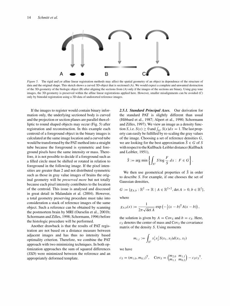
Figure 5. The rigid and\or affine linear registration methods may affect the spatial geometry of an object in dependence of the structure of
data and the original shape. This sketch shows a curved 3D-object that is sectioned (A). We would expect a complete and unwanted destruction
of the 3D-geometry of the biologic object (B) after aligning the sections from (A) only if the images of the sections are binary. Using gray tone
images, the 3D-geometry is preserved within the affine linear registrations applied here. However, smaller misalignments can be avoided (C)
only by bimodal registration using a 3D-data of undistorted reference images.
If the images to register would contain binary infor-mation only, the underlying sectioned body is curvedand the projection or section planes are parallel then el-liptic to round shaped objects may occur (Fig. 5) afterregistration and reconstruction. In this example eachcentroid of a foreground object in the binary images iscalculated at the same image location and a curved tubewould be transformed by the PAT method into a straighttube because the foreground is symmetric and fore-ground pixels have the same intensity or mass. There-fore, it is not possible to decide if a foreground such asa filled circle must be shifted or rotated in relation toforeground in the following image. If the pixel inten-sities are greater than 2 and not distributed symmetricsuch as those in gray value images of brains the orig-inal geometry will be preserved more but not totallybecause each pixel intensity contributes to the locationof the centroid. This issue is analysed and disccusedin great detail in Malandain et al. (2004). However,a total geometry preserving procedure must take intoconsideration a stack of reference images of the sameobject. Such a reference can be obtained by scanningthe postmortem brain by MRI (Ourselin et al., 2001b;Schormann and Zilles, 1998; Schormann, 1996) beforethe histologic procedure will be performed.
Another drawback is that the results of PAT regis-tration are not based on a distance measure betweenadjacent images and has thus no intensity basedoptimality criterion. Therefore, we combine the PATapproach with two minimizing techniques. In both op-timization approaches the sum of squared differences(SSD) were minimized between the reference and anappropriately deformed template.
2.5.1. Standard Principal Axes. Our derivation forthe standard PAT is slightly different than usual(Hibbard et al., 1987; Alpert et al., 1990; Schormannand Zilles, 1997). We view an image as a density func-tion S, i.e. S(x) ≥ 0 and
∫R2 S(x)dx = 1. The last prop-
erty can easily be fulfilled by re-scaling the gray valuesof the image. Choosing a set of reference densities G,we are looking for the best approximation S ∈ G of Swith respect to the Kullback-Leibler distance (Kullbackand Leibler, 1951),
S := arg min
{∫R2
S logF
Sdx : F ∈ G
}.
We then use geometrical properties of S in orderto describe S. For example, if one chooses the set ofGaussian densities,
G := {gA,b : R2 → R | A ∈ R2×2, det A > 0, b ∈ R2},where
gA,b(x) := 1
2π√
det Aexp
(− 12(x − b)T A(x − b)
),
the solution is given by A = CovS and b = cS . Here,cS denotes the center of mass and CovS the covariancematrix of the density S. Using moments
mi, j :=∫
R2
xi1x j
2 S(x1, x2)d(x1, x2)
we have
cS = (m1,0, m0,1)T, CovS =(
m2,0 m1,1m1,1 m0,2
)− cScS
T.

Image Registration of Sectioned Brains 15
Since CovS is symmetrically positive semi-definite, itpermits an eigenvalue decomposition (Golub and vanLoan, 1989)
CovS = D(ρS)S D(−ρS) (2)
where D(ρ) denotes a rotation matrix and is a scalingmatrix,
D(ρ) :=(
cos ρ −sin ρsin ρ cos ρ
), :=
(σ 2
1 00 σ 2
2
).
The geometrical features to be used are the center ofgravity cS = (cS
1 , cS2 )T, the principal axes spanned by
(cos ρS, sin ρS)T and (−sin ρS, cos ρS)T, and the stan-dard deviation of the distribution with respect to theprincipal axes, σ S
1 and σ S2 , respectively. The five pa-
rameters (cS
1 , cS2 , ρS, σ S
1 , σ S2
)(3)
can easily be determined from the moments mi, j , where(i, j) = (0, 1), (1, 0), (2, 0), (1, 1), and (0, 2).
2.5.2. Robust Principal Axes. However, as it is well-known (Kent and Tyler, 1988), Gaussian density esti-mation is sensitive to outliers in the distribution andcorrupted images due to such outliers occur frequentlyin images derived from thin histologic sections. Typicaloutliers are, for example wrinkles, disruptions, pieces
Figure 6. Results of a standard PAT and robust PAT of images with a quadratic artifact with a large mass. (a) Unperturbed image registered by
the standard PAT. (b) Unperturbed image registered by the robust PAT. (c) Perturbed image registered by the standard PAT. (d) Perturbed image
registered by the robust approach. Note, in (d) that the misregistration after robust PAT application is not as large as applying standard PAT in (c).
of tissue that were torn out and artifacts. Thus, onemay replace the set of Gaussians by the set of Cauchydensities,
C := {cA,b : R2 → R | A ∈ R2×2, det A > 0, b ∈ R2},
where
cA,b(x) := C(1 + (x − b)T A(x − b))−3/2
and the constant c has to be chosen such that∫�
cA,b(x)dx = 1. For computational issues, we referto Kent and Tyler (1988).
Cauchy density estimation leads to a more robustrepresentation of the initial image. The influence ofmass far from the image centroid becomes dampenedand thus the impact of outliers is reduced. For this rea-son, the robust approach is used throughout this paper(Fig. 6).
This phenomenon is demonstrated by comparing thegeometrical features of the section S241 with those ofthe artificially perturbed section, cf. Table 1 and Fig. 6.As it is apparent from the figure and the numbers givenin the table, the robust approach is clearly preferable.
2.6. Optimality Based Affine Linear Registration
The geometrical feature σ ν1 and σ ν
2 of the homogenizedimages are used in order to estimate the spatial exten-sions of the objects displayed. In particular we used a

16 Schmitt et al.
Table 1. Characteristics of the arbitrarily chosen image S241
(512×512 pixel) and an artificially perturbed copy using standard
and robust characteristics, see also Fig. 6.
Original Perturbed
Standard Robust Standard Robust
m 6.0 · 105 2.0 · 106 6.6 · 106 2.2 · 106
c1 165.64 167.58 181.07 173.90
c2 272.86 273.39 258.64 267.59
s1 46.31 38.20 60.09 44.01
s2 96.21 80.17 104.17 81.59
ρ −0.0146 -0.0118 0.2860 0.1363
sliding median filter of length 15 for our estimation.Note, it is impossible to recover these extensions froman individual image. If one does not pay attention to thisissue, one may map a sliced ball into a cylinder. For thisreason, we do not use a full optimization with respectto all six parameters of a affine linear transformation.
Our optimization approaches (Fig. 1) are based onthe minimization of the sum of squared differences(SSD)
SSD[R, T ; A, b] :=∑
x
(T (Ax + b) − R(x))2, (4)
with respect to the matrix A and the transformation b.In the next subsections we discuss particular choicesfor A.
For the evaluation of T (Ax +b) (T: template image,R: reference image) we exploit a bi-linear interpolationscheme and Euler coordinates. Since we are consider-ing intramodal registration this cost function can beapplied as proposed by different authors (Schormannand Zilles, 1998; Hajnal et al., 1995). Other promisingsimilarity measures like mutual information (Holdenet al., 2000) and gradient difference (Penney et al.,1998) were not investigated here.
In histological sectioning, shearing is a very likelydeformation, because the sectioning is always per-formed from one fixed direction. Therefore, our firstapproach (α-optimal), is to optimize with respect tothe shear.
In the second so-called partial-optimal approach, weoptimize with respect to rotation, shearing and transla-tion. In contrast to a full affine linear approach, the scal-ing of the transformation is not optimized but estimatedfrom global parameters of the complete histologicalseries. For both approaches the PAT registered imagesserve as starting points for a Gauss-Newton type opti-mization method.
2.6.1. Shearing Optimization (α-Optimal Approach).The optimization of the SSD with respect to the shearcomponent of the deformation starts after robust PATregistration is passed.
The affine linear map Aαx + bα between two con-secutive sections, the first one refereed to as a refer-ence (R) and the second one as a template (T ), is com-puted by minimizing the SSD (4) with respect to α ∈ Rsetting
Aα = D(−ρT )(T )12 D(α) (R)−
12 D(ρR)
and bα = cT − AαcR,
and φα(x1, x2)T := Aα(x1, x2)T +bα where cR1 , cR
2 , ρR
and cT1 , cT
2 , ρT are given by Eq. (3) for the refer-ence and template image, respectively. The basic ideais to implicitly transform reference and template im-ages into a normalized setting and than to optimizewith respect to shear. Note that the formula integratedall three steps. T ◦ φα has the same center of grav-ity and principal axes as R. The parameter α is cho-sen, in order to minimize the distance between theimages.
2.6.2. Partial Optimization (Partial-OptimalApproach). The α-optimal approach might betoo restrictive. Thus, one may also allow optimizewith respect to translation, rotation, and shearing,so-called partial-optimal. Making use of a singu-lar value decomposition of a matrix A in (4) wehave
A = Aβ,γ = D(β)(
s1 00 s2
)D(γ )
where s1 and s2 are obtained from the external esti-mates. The eigenvalue decomposition of the covari-ance matrix CovS (2) of an image S yields the rotationmatrix D(ρ) and the scaling matrix , a diagonal ma-trix that contains the scalars s1 and s2. In our partial-optimal approach we use these original scalings of asection and only optimize with respect to the remain-ing four parameters of an affine linear transformation(here: β, γ, b1, b2). Thus we optimize the SSD in (4)w.r.t. the rotation angles β, γ and the translation b1, b2
but use fixed values of s1 and s2. Therefore, the affinelinear map reads
φβ,γ,b(x) = Aβ,γ x + b.

Image Registration of Sectioned Brains 17
2.7. The Overall Affine Linear Registration
For the final registration of the image stack, thedata-based breakpoint ν0 := 241 is chosen (imagewith the maximum number of non zero pixels). LetRν0 = Sν0 and Rν = Sν(Aνx + bν) otherwise, where(Aν, bν) are computed from either the α-optimal, or thepartial-optimal approach,
(Aν±1, bν±1) = arg min{SSD[Sν, Sν±1; A, b] | A, b}
and we take the “+” sign for ν < ν0 and the “−” signfor ν > ν0. Thus, 502 optimization problems for the ratbrain sample are solved. The computations were per-formed on a Pentium III processor (1 GHz) equippedwith 4 GB RAM under Linux. The computation timeof 502 1024 × 1024 large images preprocessed as de-scribed was 13.95 minutes for standard and 84.87 min-utes for robust PAT. The shearing optimization lasted49.8 minutes and optimization of all three parameterstakes 139.43 minutes after robust PAT was finished.
2.8. Elastic Registration
As described in the introduction histologic sections areeffected by local nonlinear deformations which needto be reduced by the nonlinear approach elastic regis-tration. The rheologic equation of state concatenatesforces of tensions and distortions or extensions thatcan be determined experimentally. In most elastic mod-els the embedded brain is assumed to behave at eachpoint in the same manner with respect to deformations.Therefore, it is homogeneous with respect to materialfeatures. The brain was sectioned within a fixed di-rection, in this case from the superior to the inferiormargin in the frontal plane. Because the outer border,i.e. cerebral cortex, consists of slightly other biologicalmaterial than the white matter and the ventricles, weassume that material has more or less anisotropic fea-tures, i.e. the deformation effects of forces to the brainare depended from their direction.
In the case of the rat brain and the human forebrainthat are soaked with paraffin wax we assume a ho-mogeneous and isotropic state within sectioning. Aninhomogeneous and anisotropic state within stretch-ing the section in the warm water bath and the stain-ing procedure should be kept in mind. Because wedo not know the features of the embedded material,which is not a limiting factor for developing a gener-alizable and nonparametric nonlinear registration ap-
proach, we assume a linear relation between strain-tensor and stress-tensor. Let u(x) = (u1(x), u2(x))T
denote the displacement of a tissue particle located ata position x = (x1, x2)T ∈ R2. The Cauchy-St. Venontstrain-tensor is denoted by V and the stress-tensor by,
V : =(ε1,1 ε1,2ε2,1 ε2,2
):= 1
2(∇u + ∇uT),
: =(σ1,1 σ1,2σ2,1 σ2,2
). (5)
Exploiting the homogeneity of the tissue sections, thestrain- and stress tensor are simultaneously diagonal-izable and can be rewritten in terms of an eigenvectorbasis. Let the eigenvalues of V and be denoted by ε j
and σ j , j = I, I I , respectively. Moreover, under thehomogeneity assumption, a linear model becomes(
εIεI I
)=
(E −υE
−υE E
) (σIσII
)(6)
with some parameters E, υ ≥ 0, which are known asYoung’s elasticity module and Poissons’s contractionration. Introducing the so-called Lame-constants
μ := E
2(1 + υ)and λ := Eυ
(1 + υ)(1 − υ), (7)
Eq. (6) can be rewritten in general coordinates,
σ j,k = 2με j,k + λ trace(V ) δ j,k
= μ(∂x j uk + ∂xk u j ) + λ div u δ j,k, j, k = 1, 2,
where δ j,k = 1, if j = k, and 0 otherwise. Theseequations describe the inner forces in a linear modelof an elastic body. Let f denote an outer force-field.From Eq. (8) the equilibrium equation f j = div j :=∂x1
σ j,1 + ∂x2σ j,2, j = 1, 2 which balances inner and
outer forces, we obtain the Navier-Lame-equations
μ�u1 + (λ + μ)∂x1div u = f1,
μ�u2 + (λ + μ)∂x2div u = f2.
A more general approach to image registration isbased on the minimization of the joint functional
J [u] = D[R, T ; u] + αS[u], (8)
where R, T : R2 → R denotes the two images to beregistered, D denotes an appropriate distance measure,

18 Schmitt et al.
e.g., the so-called sum of squared differences
D[R, T ; u] = 1
2
∫R2
(T (x − u(x)) − R(x))2 dx, (9)
and S denotes a regularizer, e.g., the elastic potential
S[u] = 1
2
∫R2
λ(∂x1
u1 + ∂x2u2
)2 + μ{2(∂x1
u1
)2
+ 2(∂x2
u2
)2 + (∂x2
u1 + ∂x1u2
)2}dx,
and α > 0 denotes a regularizing parameter(cf., Fischer and Modersitzki, 2002). The basicidea thus is to find a deformation of a template image(T ) that simultaneously minimizes the differencebetween the deformed template and the referenceimage (R) and the deformation energy, respectively.This approach enforces similarity of the images aswell as connectivity of the tissue. Note, in this notationT (x − u(x)) might be viewed as the non-deformedversion of the template. Using the calculus of variation,a minimizer of (8) is characterized by
− f (u) + A[u] = 0,
where
f (x, u(x)) = (T (x − u(x)) − R(x)) · ∇T (x − u(x)),
A[u] = αμ�u + α(λ + μ)∇ div u.
These are the Navier-Lame equations with a particularforce-field which stem from the Gateaux-derivative ofthe distance measure (9).
An appropriate discretization of these equations fi-nally leads to a fixed-point type equation for the un-known deformation field, cf. Eq. (10),
A(u(k+1)
1 , u(k+1)2
)T = (
f1
(u(k)
), f2
(u(k)
))T. (10)
2.9. Implementation
In principle, any method for solving a system of lin-ear equations can be used to compute the solution ofEq. (10). However, a discretization of u1 and u2 withm × n points results in N = 2mn unknowns (e.g.for 512 × 512 discretization points we end up withN = 219 = 524288) and A becomes N × N . For astandard LU -decomposition one needs to store O(N 2)real numbers and approximately O(N 3) floating pointoperations (see, e.g. Golub and van Loan, 1989). Thus,
memory and computational requirements afford a par-ticular treatment.
The implementation of our parallel algorithm forp processors can be divided into three parts (seeModersitzki et al., 1999) for a detailed description ofthe implementation on a 48 dual pentium cluster.
Let X1 and X2 refer to a spatial grid and U j =u j ( X1, X2)T denote the values of the displacement fieldon the spatial grid. In an initialization step we set theiteration counter k = 0, U (k)
1 = U (k)2 = 0. In the iter-
ation, we compute the deformed template T (k)(x) :=T (x − u(k)(x)) on the actual grid by using a bilinearinterpolation scheme. Let (x1, x2) ∈ [1, m] × [1, n],ξ j := x j − u j (x1, x2), d j ∈ N, j = 1, 2, such thatd j ≤ ξ j < d j + 1. Then,
T (k)(x1, x2) = T (d1, d2)(d1 + 1 − ξ1)(d2 + 1 − ξ2)
+ T (d1 + 1, d2)(ξ j − d1)(d2 + 1 − ξ2)
+ T (d1, d2 + 1)(d1 + 1 − ξ1)(ξ2 − d2)
+ T (d1 + 1, d2 + 1)(ξ1 − d1)(ξ2 − d2).
Using centered finite difference approximations for thederivatives, the actual force field on the spatial grid canbe computed by
F (k)1 (x1, x2) = (
T (k)(x1, x2) − R(x1, x2))
·T (k)(x1 + 1, x2) − T (k)(x1 − 1, x2)
2,
F (k)2 (x1, x2) = (
T (k)(x1, x2) − R(x1, x2))
·T (k)(x1, x2 + 1) − T (k)(x1, x2 − 1)
2,
where T (k)(x) = 0 if (x1 − u(k)1 (x), x2 − u(k)
2 (x) �[1, m] × [1, n]) is not a grid point.
The linear system (10) is solved and computationis terminated if one of the three following conditionsholds
‖u‖ � 1, ‖ f (k)‖ � 1, ‖R − T (k)‖ � ‖R − T ‖.
If we want to preserve and visualize histologic detailslike the lamination pattern of the cerebral cortex imagesof a minimal size of 512×512 pixels must be registered.Therefore, Fischer and Modersitzki (1999, 2001) havedeveloped a fast solver based on the inverse Fast FourierTransform that was also implemented in parallel on ahigh performance cluster (Bohme et al., 2002).

Image Registration of Sectioned Brains 19
Figure 7. Overview of the 3D-reconstructions of (a) the original non-registered image stack (b) of the robust principal axes transformation,
(c) of the shearing optimization and (d) optimization of translation, rotation and shearing. On the left side 3D-reconstructions without linear
smoothing and on the right linear smoothed 3D-reconstructions are shown.
3. Results
3.1. Affine Linear Registration of the Rat Brain
In Fig. 7, the 2D-projections of 3D-reconstructed ratbrain images are presented. The reconstructions areplotted in a smoothed and a non-smoothed version, re-spectively. All reconstructions depict the same viewpoint of the brain. The non-registered image stackshows a blurred surface. The typical ellipsoid form ofthe 3D-body of the rat brain looks like a tube. At the ros-tral region small pieces of tissue lie somewhere in frontof the telencephalon. These pieces of tissue belong tothe olfactory bulb resp. accessory olfactory bulb. The
cerebellum can be guessed by the posterior third in thereconstruction because there the surface seems to bemore rough.
After applying exclusive PAT registration, the cor-rect proportionated 3D-body of the rat brain, its surface,and macroscopic visible details like the longitudinalcerebral fissure, the cerebral hemispheres and the cere-bellum with its lobes and lobules are identifiable. Thesmall tissue sections of the olfactory bulb are alignedto their correct locations by the PAT.
The same results as described visually with re-spect to the 3D-reconstructions were found quanti-tatively, too. The robust PAT method leads in bothexamples of original and perturbed images to lower

20 Schmitt et al.
Figure 8. A region of interest within the longitudinal fissure of the
rat brain (Fig. 7) is shown here in order to demonstrate details of
the alignment. (a) PAT registration; (b) PAT registration plus shear-
ing optimization; (c) PAT registration plus translation, rotation and
shearing optimization. The surface of the 3D-reconstruction in (c) is
slightly smoother. This means that the optimization of three param-
eters leads to a better result.
differences and therefore to a better registration result(Table 1).
Optimizing the translation after applying the robustPAT registration leads to a minor refinement of the sur-face of the brain reconstruction. The fact that a minorrefinement is reached after the α-optimal approach canbe seen more clearly after reconstructing a region ofinterest (ROI) around the longitudinal cerebral fissure(Fig. 8). The margin of the fissure is at some locationssmoother than at the exclusive PAT registrations indi-cating that the adjacent images are better aligned.
The best quality of affine linear registration is de-livered by the partial-optimal approach. Translation,shearing and rotation features are optimized after ap-plying the robust PAT. The result is obviously betterresp., the surface of the 3D reconstructed rat brain issmoother than in the α-optimal approach. This can beseen quite clearly in the 3D-reconstruction of the ROIas shown in Fig. 8(c).
Additionally, the mean SSDs of all methods for asample of 21 adjacent images (330–350) of an embed-ded size of 1024 × 1024 pixels were calculated. Thenon-registered stack has a mean SSD of 36171. RobustPAT leads to a decrease of 47% and the standard PATto 49% of the SSD. If shearing is optimized after ro-bust PAT (55%, x = 16236.84) or standard PAT (55%,x = 16239.95) has been applied a further decreasewas observed. The SSD of the robust PAT after rota-tion and translation optimization is 52%. Therefore, theshearing component contributes more to the deforma-tion than rotation and translation within the affine lin-ear registration step. The smallest SSD (59%) was cal-culated for the robust partial-optimal approach wheretranslation, rotation and shearing have been optimized.
Different registration techniques lead in general tocompletely different reconstructions. Thus, there is inprincipal, no one-to-one correspondence between hor-izontal and sagittal sections of the 3D-reconstructionsof the three different registrations. These visual impres-sions as described above can be recognized in isopla-nar projections of the 3D-reconstructions, too (Fig. 9).Naturally, such virtual sections are only reasonable af-ter registration and reconstruction. Therefore, the im-age processing chain has to be considered as an ade-quate constrain with resp. to the visualization of finermorphologic structures at high resolutions in these iso-planar sections. Such a fine structure can be seen in thehorizontal isoplane in the brainstem (Fig. 10: e.g. abdu-cence nucleus, trigeminal nucleus). The hippocampusformation and even the molecular layer of the cerebellar

Image Registration of Sectioned Brains 21
Figure 9. Isoplanar sections through 3D-reconstructions of three different registrations are presented here in the horizontal (left) and sagittal
plane (right) for (a) PAT registration; (b) PAT registration plus shearing optimization; (c) PAT registration plus translation, rotation and shearing
optimization.
cortex can be seen clearly. The white matter boarderof the cerebral cortex and the boarder of the molecularlayer to the layer of the cerebellum can be differentiatedas well. As mentioned before, it must be clear thatthe isoplanar sections of the exclusive PAT, α-optimaland partial-optimal approaches cannot be compareddirectly with respect to certain details because the opti-
mization of shearing alone or shearing in combinationwith translation and rotation effect the 3D-geometryof the brain and consequently the positioning of smallstructures (Fig. 9). However, to make our results com-parable, the most similar sections w.r.t. anatomic fea-tures were selected (original data: horizontal 299, sagit-tal 180; PAT: horizontal 303, sagittal 180; α-optimal:

22 Schmitt et al.
Figure 10. Isoplanar sections through 3D-reconstructions visualized with a colored look-up-map. The black line in the panel above indicates
the view on a section of the reconstruction below. This section contains the data of one original image.
horizontal 303, sagittal 180; partial-optimal: horizon-tal 299, sagittal 165). Here, the original stacked im-ages and the PAT images share the same section num-ber and can be compared directly. Note, the originalnon-registered stacked images cannot be used. An iso-planar section in the PAT image looks more like theisoplanar section in the α-optimal result than in thepartial-optimal reconstructed result. However, we triedto choose isoplanar sections which are as similar aspossible.
At last the 3D-reconstruction of a 512 × 512 pixelslarge resampled stack of images is reproduced in Fig.11. In the same figure, we have also reconstructed thesame stack of images at original resolution of 6.35μm edge length of each pixel. The first rostral sec-tions of the olfactory bulb are misregistered becausewe applied a smaller opening filter (5 × 5) in orderto preserve finer details at such a high resolution. De-spite the fact that we applied the robust PAT registra-tion strategy, the sections are not aligned optimally.

Image Registration of Sectioned Brains 23
Figure 11. The best quality of registration was obtained by the partial-optimal approach (upper panel: registration and reconstruction of low
resolution images). Therefore, the whole stack of images was registered partial-optimal at the original relative large resolution. The resulting
reconstruction is shown in the lower panel.
This is because small preserved artifacts around fore-ground objects which do not pertain to the class ofartifacts posses only small masses in comparison toother structures. Hence, they gain a stronger influenceon the center of mass and the orientation of the princi-pal axes. Nevertheless, those sections which possesseslarge masses show an optimal affine alignment result.Interestingly, one can recognize the granule cell layer ofthe main olfactory bulb which cannot be detected in thereconstruction of the image of lower resolution (sameFig. 11).
3.2. Elastic Registration of the Rat Brain
The SSD of the preregistered rat brain images decreasesfrom 281373 (59%) to 229576 (67%) in comparisonwith the nonregistered images. After 10 steps of elasticregistration were performed we observed the largest in-crease of SSD. From 20 to 40 further registration stepsthe SSDs diminishes to 204241, i.e. 70%. The elas-tic registration of preprocessed but not preregisteredimages yields to a decrease after 40 steps of the SSDto 422969 (38%), only. This means that affine linear

24 Schmitt et al.
Figure 12. The 3D-reconstructions of the rat brain after affine linear registration (LR) and affine linear with subsequent elastic registration (ER)
after 10 to 50 registration steps. Two different projections are shown here: from above (left column) and oblique from the rostral perspective
(right column). The smoothness of the surface of the reconstructed brain is correlated with the number of registration steps.
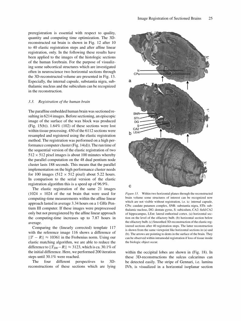
Image Registration of Sectioned Brains 25
preregistration is essential with respect to quality,quantity and computing time optimization. The 3D-reconstructed rat brain is shown in Fig. 12 after 10to 40 elastic registration steps and after affine linearregistration, only. In the following these results havebeen applied to the images of the histologic sectionsof the human forebrain. For the purpose of visualiz-ing some subcortical structures which are investigatedoften in neuroscience two horizontal sections throughthe 3D-reconstructed volume are presented in Fig. 13.Especially, the internal capsule, substantia nigra, sub-thalamic nucleus and the subiculum can be recognizedin the reconstruction.
3.3. Registration of the human brain
The paraffine embedded human brain was sectioned re-sulting in 6214 images. Before sectioning, an episcopicimage of the surface of the wax block was produced(Fig. 15(b)). 1.64% (102) of these sections were lostwithin tissue processing. 450 of the 6112 sections wereresampled and registered using the elastic registrationmethod. The registration was performed on a high per-formance computer cluster (Fig. 14(d)). The run time ofthe sequential version of the elastic registration of two512 × 512 pixel images is about 100 minutes wherebythe parallel computation on the 48 dual pentium nodecluster lasts 188 seconds. This means that the parallelimplementation on the high performance cluster needsfor 100 images (512 × 512 pixel) about 5.22 hours.In comparison to the serial version of the elasticregistration algorithm this is a speed up of 96.9%.
The elastic registration of the same 21 images(1024 × 1024 of the rat brain that were used forcomputing-time measurements within the affine linearapproach lasted in average 3.34 hours on a 1 GHz Pen-tium III computer. If these images were preprocessedonly but not preregistered by the affine linear approachthe computing-time increases up to 7.87 hours inaverage.
Comparing the (linearly corrected) template 117with the reference image 116 shows a difference of||T − R|| ≈ 10361 in the Frobenius norm. Using ourelastic matching algorithm, we are able to reduce thedifference to ||T200−R|| ≈ 3123, which is ca. 30.1% ofthe initial difference. Here, we performed 200 iterationsteps until 30.1% were reached.
The four different perspectives to 3D-reconstructions of these sections which are lying
Figure 13. Within two horizontal planes through the reconstructed
brain volume some structures of interest can be recognized now
which are not visible without registration, i.e. ic: internal capsule,
CPu: caudate putamen complex, SNR: substantia nigra, STh: sub-
thalamic nucleus, DG: dentate gyrus, S: subiculum, CA2: field CA2
of hippocampus, LEnt: lateral enthorinal cortex. (a) horizontal sec-
tion on the level of the olfactory bulb. (b) horizontal section below
the olfactory bulb. (c) Smoothed 3D-reconstruction of the elastic reg-
istered sections after 40 registration steps. The latter reconstruction
is shown from the same viewpoint like horizontal sections in (a) and
(b). The arrows are pointing to dents in the surface of the brain. They
can be observed within intramodal registration if loss of tissue inside
the biologic object occur.
within the occipital lobes are shown in (Fig. 18). Inthese 3D-reconstructions the sulcus calcarinus canbe detected easily. The stripe of Gennari, i.e. laminaIVb, is visualized in a horizontal isoplanar section

26 Schmitt et al.
Figure 14. The sliding microtome with the scanner camera that have been used for digitizing each paraffin wax block surface before the next
section have been produced (a), a deformed 20 μm section on the knife of a microtome (b), a large histologic section on the high resolution
transparent flat bed scanner (c), the high performance computer cluster with 48 dual PII processors (d).
through the 3d-reconstruction (Fig. 19). The neuronpoor lamina IVb can be seen better in area 17 of theright occipital lobe. Gyral structures that have been
sectioned tangentially and are not connected to thetissue object with the largest area of all tissue objects inan image were matched in correct topographic relation.

Image Registration of Sectioned Brains 27
Figure 15. (a) The brain that have been processed was evaluated by
an MRI-scanner (MRI-modality). (b) Paraffin wax surfaces were dig-
itized before each sectioning process (episcopic modality). (c) High
resolution flat bed scan images were produced from each histologic
section of the investigated brain (FBS modality).
Finally, we have used the force fields calculatedby the elastic registration algorithm in order to de-termine in four consecutive sections (116 to 119)the exact centers of gravitation of each neuron(Fig. 20). The gravitation centers have been de-tected before by a image analytical procedure de-scribed by Schmitt et al. (2005). The registrationof the gravitation centers of the detected cells and
reconstruction is shown in Fig. 21. The cortex, lam-ina I and II as well as the white matter bordercan be detected easily in the registered object data.
4. Discussion
4.1. The Registration Chain: From Affine to Elastic
The result of the proposed approach of robust affinelinear registration is a reliable alignment of histo-logic sections of a whole brain of a rat that showsin 3D-reconstructions structures which were not vis-ible before registration. The robustness of the algo-rithm that was implemented is an outstanding fea-ture in regard to the alignment of histologic mate-rial. Because it has a very low sensitivity to noisewe will use it for a fast pre-registration. The pre-aligned images are a promising starting point for aconsecutive nonlinear registration which will spendless computing time than without pre-registrationbecause the convergence will be reached sooner.
4.2. The Affine Linear Approaches
We have presented different approaches to affine lin-ear registration. Because the standard PAT of histologicimages leads to unwanted trends in the registration re-sult, we must recommend our robust version. Priorstudies describe other algorithms which were devel-oped for rigid transformations (Kuglin and Hines,1975; de Castro and Morandi, 1987; Hibbard et al.,1992; Zhao et al., 1993; Alexander et al., 1997). How-ever, these approaches are not as flexible as the tech-nique investigated here with respect to subsequentoptimizations. These optimizations may concern thetranslation (2 parameters), the rotation (1 parameter)and the shearing (1 parameter) as well as the scal-ing (2 parameter). Applying optimization of the firstthree components (translation, rotation, shear) leadsto smoother surfaces in the 3D-reconstructions and tothe smallest SSD. Finer details, convexities and con-cavities are preserved. Recently, Arsigny et al. (2005)developed a polyrigid and polyaffine transformationthat was applied sucessfully to histologic sections.
As explicated before, affine linear registration offoreground structures in stacks of images are alignedin reference to their centroids. These centroids are spa-tial points of convergence of the foreground structures.

28 Schmitt et al.
Figure 16. Top: The size of the foreground (ordinate) within each image of the whole series of digitizes histologic sections (abscissa) of the
human forebrain is presented here. Below: In this diagram the smoothed distribution of foreground areas is shown. In the left part of this diagram
section size increases slower (frontal lobe) whereby on the right side the decrease of section size is stronger within the parietal and occipital
lobe.
Since no external references (e.g. fiducial markers)were used in this kind of registration it is morelikely that sections through a curved cylinder con-verge to a tube like object after reconstruction (Fig. 5).
Scaling optimization was not considered here be-cause all images are digitized at the same magnifi-cation and resolution. Moreover, deformations effect-ing the scaling or larger local volume bulges of thebrain do not appear. However, scaling have to be keptin mind because single sections may be compressedalso and therefore need to be registered in respectof scaling. Since now, we are not able to recom-
mend an affine linear method or a nonlinear methodto align distortions due to compression or dilation.
These observations suggest that, compared toother algorithms, e.g. chamfer matching (You, 1995;Borgefors, 1988), fiducial markers (Ongaro et al.,1991; Maurer et al., 1997; Kremser et al., 1997;de Munck et al., 1998; West et al., 2001) and otherimplementations (Ozturk, 2002; Woods, 2002), ourrobust rigid registration combined with affine linearoptimization of translation, rotation and shearing leadto an optimal starting point for a succeeding nonlinearregistration technique.

Image Registration of Sectioned Brains 29
Figure 17. A template image (T) of a section (above) and a reference image (R) of a consecutive section (middle) are shown. The foreground
objects, i.e. views of the occipital lobes) in the images do not match exactly (below).
Ourselin and coauthors (Ourselin et al., 2001b)investigated registration robustness of comparablematerial as done here. They have shown by a newsophisticated approach the block matching algorithmapplied to digitized histologic images that have tobe registered and using the correlation coefficientas an appropriate similarity measure satisfying re-constructions can be obtained. They used a robustestimate, the convex M-estimator or L1-estimatorthat is suitable for point matching to generate reliableresults. So far, we do not have implemented this tech-nique which is of interest for comparison of robustnessissues.
As elaborated by Schormann and Zilles (1997) andSchormann et al. (1997) minute shearing results instrong rotational errors if the shapes are approximatelysquare, but scaling errors dominate in cases with ex-
tensive shearing can be minimized by combine therobust PAT approach introduced here by consecu-tive affine optimizations. Small misalignments of ad-jacent sections can be corrected much faster by anelastic method after preregistration with the robustpartial-optimal technique than direct by the elastic ap-proach because the extension of mismatch was previ-ously reduced. Furthermore, affine preregistration be-fore elastic registration may have a direct qualitativeeffect of preserving the morphology of the histologicstructures. If the global deformation components liketranslation, rotation and shearing are registered pri-mary local by a nonlinear approach local deforma-tions can be introduced into the resulting images.
We must emphasize that the partial-optimal ap-proach is a necessary initial registration proce-dure. However, an affine linear model is not

30 Schmitt et al.
Figure 18. 3D-reconstructions of the elastic registered images 100 to 199. Here, four different views to the reconstructed stack of images are
presented.
sufficient to register images that contain non-linear deformations. Therefore, it is indispens-able to align images of serial histologic sec-tions in a multiresolution-multiregistration frame-work for a best possible correction of deformations.
4.3. Elastic Registration and Megapixel Images
After pre-alignment the images still contain deforma-tions (Fig. 9(c)) that are local and nonlinear. Suchlocal deformations are getting more important if im-ages of histologic sections with high resolution up toa coarse cellular presentation are registered. So far weare not able to determine if the remaining deformationsare attributed to small affine linear distortions. Never-theless, the affine linear pre-alignment have reachedan optimum. Therefore, a local nonlinear techniquelike elastic registration is an inevitable procedure fora consequent final alignment of histologic images.
The theoretical framework of elastic registration hasbeen published first 20 years ago by (Broit, 1981;
Bajcsy, 1982; Bajcsy, 1983; Bajcsy and Kovacıc,1989). This kind of local and nonlinear intensitybased registration was applied to histologic sections(Schormann, 1996; Schormann and Zilles, 1998) in-tramodal (MRI to MRI) and intermodal (histologic toMRI). Some subsequent works about nonlinear regis-tration of inter- and intramodal elastic alignment wherehistologic image data were involved have been pub-lished by Mega et al. (1997), Cohen et al. (1998),Jacobs et al. (1999), Bardinet et al. (2001), Toga andThompson (2001) and Ourselin et al. (2001a,b). How-ever, in these works no high resolution image dataare used and no computing optimizations were real-ized. Therefore, we have developed a parallel imple-mentation of a fast solver of the equation systems tomaintain the force fields and the results of our non-linear approach are presented here for the first time.
In comparison to other elasticity based registrationsof MRI, PET or other material (Davatzikos, 1997; Ash-burner et al., 2000; Hayakawa et al., 2000; Iosifescuet al., 1997; Ferrant et al., 2001; Guimond et al.,2001; Christensen and Johnson, 2001; Christensen

Image Registration of Sectioned Brains 31
Figure 19. On top the perspective on the 3D-reconstruction form above is displayed. A virtual section through the 3D-reconstruction has been
performed. In the isoplanar view somebody can detect the stripe of Gennari (arrows) within area 17 and the calcanear sulus (black lines).
et al., 1997; du Bois d’Aische et al., 2005; Aueret al., 2005) we are working with very large im-ages of up to 11000 × 7000 (= 77 × 106) pixels.The resulting system of linear equations has a size of1.40612164 × 1032 (= 4 × n4). Therefore, Fischerand Modersitzki (1999, 2001) developed a superfastdirect solution scheme (full multigrid), based on theFast Fourier Transformation. In addition, this solutionscheme has been implemented on a high performancecomputer cluster. An alternative would be solvingthe equation system by a parallelized additive oper-ator splitting (AOS) technique or parallelized multi-
grid computing (Thompson and Ferziger, 1989; Vatsaand Wedan, 1990; Schieweck, 1993; Webster, 1994).
4.4. Nonlinear Registration Alternatives to theElastic Approach
An alternative to the elastic approach would bethin plate splines with landmarks (Bookstein, 1984,1989; Davatzikos and Prince, 1994; Davatzikos,1997; Maurer et al., 1997; Rangarajan et al., 1997;Baheerathan et al., 1998; Cohen et al., 1998; Gold et al.,

32 Schmitt et al.
Figure 20. Within section 115 to 119 each cell was detected. Each 40th cell has been plotted on the left side of this plate. The corresponding
FBS-image is shown on the right. Section 118 was slightly thinner. Therefore, we found fewer cells within the section space.
1998; Kostelec et al., 1998; Rangarajan et al., 1999;Joshi and Miller, 2000; Chui et al., 2001; Johnson andChristensen, 2001; Rohr et al., 2001), trilinear Beziersplines (B-splines) (Rueckert et al., 1999; Otte, 2001),nonlinear registration via genetic algorithms (Rouetet al., 2000) or deformable organisms (autonomousagents) derived from artificial life computing concepts(Hamilton et al., 2001). However, landmarks haveto be determined exactly which could be a limitingfactor for very complex series of images (Collinset al., 1995; Likar and Pernus, 1999; MacDonald et al.,2000). Other non-linear methods like optical flow(Horn and Schunck, 1981; Hellier et al., 2001) andfluid dynamic models (Christensen, 1994; Christensenet al., 1997; Lester and Arridge, 1999; Christensenand Johnson, 2001) which are applied for matchingimages of different modalities or between different
individuals have to many degrees of freedom. Thiscould lead to problems at those parts of images wereloss of tissue or larger cracks and crinkles are present.Furthermore, the physical effects which introducedeformations consists of extension (dilatation) andtension (contraction) forces and not of movementartifacts (optical flow) or applying a registration taskto images which are derived from different physicaldevices or which should be registered to differentindividuals.
4.5. Similarity Measures
In our approach of elastic registration only onedistance measure was applied. According to Penneyet al. (1998), Studholme et al. (1999), Holden et al.(2000) and Zhu (2002) other measures of similarity

Image Registration of Sectioned Brains 33
Figure 21. A region of interest of the object data was aligned using the result of the elastic registration of FBS-images 116 to 119. Laminar
details and the white matter border can be detected in the plots of each gravitation center of the cells. On the right we have plotted the 3D-particle
space of the aligned object data.

34 Schmitt et al.
can be used too. Therefore, we will investigate furthersimilarity measures.
4.6. Drawbacks
Rohlfing and Maurer (2001) pointed out that the vol-ume of contrast-enhancing structures are decrease af-ter elastic registration. This effect can be reduced byan incompressibility constraint approach based on theJacobian determinant of the deformation that can becomputed rapidly. Such a constrained elastic registra-tion have to be tested on our image material. If thisapproach would preserve fine contrast details of thelaminar structure then we would be able to analyze thelamination pattern of the cortex in three dimensions.
Since now, the images of the histologic sectionswere not registered bimodaly to a reference data setthat can be obtained from MRI. A further approachwas published by Gefen et al. (2003) who developedregistration of a rat brain to internal and external sur-faces serving as guides or surface references. An in-trasubject reference of the rat brain used here is notavailable. Nevertheless, the intramodal elastic regis-tration decreases the SSD and increases the quality ofthe reconstructed morphology. The arrows in Fig. 13are pointing to dents of the rat brain surface whichdo not occur normally. If sections with some loss oftissue inside the brain are registered the image struc-tures can be pulled more and more inside the volumein order to minimize the SSD. This can be preventedby a bimodal registration of the histologic data set to aprehistologic MRI-dataset of the same biologic object.
4.7. Other Applications
Nonlinear registration schemes (elastic solid, fluid vis-cous, mutual information, optical flow) are the scaf-folding for co-registration and multimodal registrationstrategies that are used for atlas development (Thur-fjell et al., 1995; Toga et al., 1995; Nowinski et al.,1997; McInerney and Roberts, 1998; Juan et al., 2000;Nowinski and Thirunavuukarasuu, 2001), computeraided surgery (Maurer et al., 1998a,b,c; Woods et al.,1999; Jannin et al., 2000; Rohlfing et al., 2000; Murphyet al., 2001; Mutic et al., 2001; Watanabe et al., 2001;Sabbah et al., 2002) and structure-function-data cor-relation investigations (Mega et al., 1997; Viergeveret al., 1997). Multimodal registrations deliver objec-tive approaches that enable easy and intuitive image
registration. This can be of great help for the physicianwho arrive at more optimal diagnoses and better treat-ment decisions. Beside the development of atlases forsurgery tasks nonlinear registration, in particular fluidmodels with more degrees of freedom, is essential formatching single subject data sets to group data sets forevaluation and comparison of macroscopic brain simi-larities as well as differences (Santori and Toga, 1993).
4.8. AIR
The registration software package AIR 5.06(Woods et al., 1998a,b) (http://128.97.134.164/
AIR5/index.html) is able to perform affine linearand nonlinear registrations as well as co-registrations(Kiebel et al., 1997). However, as already shownby Hsu et al. (2001), registration results can beenhanced by other methods and modifications.
4.9. Closing Words
Elastic registration of high resolution images of serialhistologic sections of the human brain is quantitativelyaccurate and provides an registered stack of imagesthat can be directly reconstructed and rendered. The re-constructions, once completed, offers insights into thespatial arrangement of morphologic entities like dif-ferent cortical regions, laminae, subcortical nuclei andfiber tracts which are the origin for exact 3D cellularobject reconstructions as shown exemplary. Therefore,we are confident to apply this introduced, modifiedand successful tested registration framework fromthe preprocessing over affine and elastic alignment to3D-reconstruction and rendering to the whole highresolution data set of over 6000 sections of a humanbrain.
Acknowledgments
We thank U. Almert, P. Lau, E. Mecke of theInstitute of Anatomy (University of Lubeck) fortheir excellent histologic preparations, digitizing anddata administration, W. Kuhnel and J. Westermann(Institute of Anatomy, University of Lubeck) for theirextensive support, S. Prehn (Institute of TechnicalInformatics, University of Lubeck) for optimizingand administration the SF 15K computer on whichseveral computing experiments were performed. Weare indebted to Prof. Dr. Lutz Dumbgen for valuable
Image Registration of Sectioned Brains 35
comments and helpful discussions concerning thestochastic questions. We gratefully acknowledgeMartin Bohme and Susanne Bock for programminggraphical user interfaces. Furthermore, we haveto express our gratitude to A. Wree (Institute ofAnatomy, University Rostock) for his importantsuggestions and critical discussion of this study. M.Westlund was of great help editing and correcting themanuscript. This work was supported by the GerhardTen Doornkaat Koolman foundation and the Possehlfoundation.
References
Abbe, E. 1873. Beitrage zur Theorie des Mikroskops und der
mikroskopischen Wahrnehmung. Arch. Mikr. Anat., 9:413.
Abeles, M. 1991, Corticonics. Neural circuits of the cerebral cortex.
Cambridge University Press: Cambridge.
Aferzon, J., Chau, R., and Cowan, D. 1991. A microcomputer-based
system for three-dimensional reconstructions from tomographic
or histologic sections. Anal. Quant. Cytol. Histol., 13:80–88.
Alexander, M., Scarth, G., and Somorjai, R. 1997. An improved
robust hierarchical registration algorithm. Magn. Reson. Imaging.,15:505–514.
Alpert, N., Bradshaw, J., Kennedy, D., and Correia, J. 1990. The
principal axes transformation—a method for image registration.
J. Nuc. Med., 31:1717–1722.
Amit, Y., Grenander, U., and Piccioni, M. 1991. Structural im-
age restoration through deformable templates. J. Am. Stat. Ass.,86:376–387.
Arbib, M. 1995, The Handbook of Brain Theory and Neural Net-works. MIT Press: Cambridge.
Arsigny, V., Pennec, X., and Ayache, N. 2005. Polyrigid and
polyaffine transformations: A novel geometrical tool to deal with
non-rigid deformations—Application to the registration of histo-
logical slices. Med. Image. Anal., 9:507–523.
Ashburner, J., Andersson, J., and Friston, K. 2000. Image registration
using a symmetric prior–in three dimensions. Hum. Brain. Mapp.,9:212–225.
Auer, M., Regitnig, P., and Holzapfel, G. 2005. An automatic non-
rigid registration for stained histologic sections. IEEE Trans. Imag.Proc., 14:475–486.
Baheerathan, S., Albregtsen, F., and Danielsen, H. 1998. Registration
of serial sections of mouse liver cell nuclei. J. Microsc., 192:37–
53.
Bajcsy, R. 1982. Matching of deformed images. Proc. 6th Int. Conf.Patt. Recogn., 6:351–353.
Bajcsy, R. 1983. A computerized system for the elastic matching of
deformed radiographic images to idealized atlas images. J. Comp.Ass. Tomo., 7:618–625.
Bajcsy, R. and Kovacıc, S. 1989. Multiresolution elastic matching.
Comp. Vis. Image. Proc., 46:1–21.
Banerjee, P. and Toga, A. 1994. Image alignment by integrated ro-
tational and translational transformation matrix. Phys. Med. Biol.,39:1969–1988.
Bardinet, E., Colchester, A., Roche, A., Zhu, Y., He, Y., Ourselin, S.,
Nailon, B., Hojjat, S., Ironside, J., Al-Sarraj, S., Ayache, N., and
Wardlaw, J. 2001. Registration of reconstructed post mortem opti-
cal data with MR scans of the same patient. LNCS, 2208:957–965.
Barnard, S. and Thompson, W. 1980. Disparity analysis of images.
IEEE Trans. PAMI, 2:333–340.
Barnea, D. and Silverman, H. 1972. A class of algorithms for fast
digital image registration. IEEE Trans. Comp., 21:179–186.
Baumann, M. and Scharf, H. 1994. Moderne Bildverarbeitungsver-
fahren als Unterstutzung der raumlichen Rekonstruktion histolo-
gischer Strukturen. Ann. Anat., 176:185–188.
Benveniste, H. and Blackband, S. 2002. MR microscopy and high
resolution small animal MRI: Applications in neuroscience re-
search. Prog. Neurobiol., 67:393–420.
Bohme, M., Hagenau, R., Modersitzki, J., and Siebert, B. 2002. Non-
linear image registration on PC-clusters using parallel FFT tech-
niques. Technical Report SIIM-TR-A-02-08, Institute of Mathe-
matics, Medical University of Lubeck.
Bookstein, F. 1984. A statistical method for biological shape com-
parisons. J. Theor. Biol., 107:475–520.
Bookstein, F. 1989. Principal warps: Thin-plate splines and the de-
composition of deformations. IEEE Trans. Patt. Anal. Mach. In-tell., 11:567–585.
Borgefors, G. 1988. Hierarchical chamfer matching: A parametric
edge matching algorithm. IEEE Trans. PAMI, 10:849–865.
Born, G. 1883. Die Plattenmodellirungsmethode. Arch. Mikr. Anat.,22:584–599.
Braitenberg, V. 1978. Cell assemblies in the cerebral cortex. Lec.Notes. Biomath., 21:171–188.
Bro-Nielsen, M. and Gramkow, C. 1996. Fast fluid registration of
medical images. LNCS, 1131:267–276.
Broit, C. 1981. Optimal registration of deformed images. Ph.D. the-
sis, Computer and Information science, University of Pensylvania.
Bron, C., Launay, D., Jourlin, M., Gautschi, H., Bachi, T., and
Schupbach, J. 1990. Three dimensional electron microscopy of
entire cell. J. Mircosc., 157:115–126.
Brown, L. 1992. A survey of image registration techniques. ACMComp. Surv., 24:325–376.
Budo, A. 1990, Theoretische Mechanik. VEB Deutscher Verlag der
Wissenschaften.
Christensen, G. 1994. Deformable shape models for anatomy. Ph.D.
thesis, Sever Institute of Technology, Washington University.
Christensen, G. and Johnson, H. 2001. Consistent image registration.
IEEE Trans. Med. Imaging., 20:568–582.
Christensen, G., Joshi, S., and Miller, M. 1997. Volumetric transfor-
mation of brain anatomy. IEEE Trans. Med. Imaging., 16:864–877.
Chui, H., Win, L., Schultz, E., Duncan, J., and Rangarajan, A. 2001.
A unified feature registration method for brain mapping. LNCS,
2082:300–314.
Ciarlet, P. 2000. Mathematical Elasticity. Elsevier Science.
Cohen, F., Yang, Z., Huang, Z., and Nissanov, J. 1998. Auto-
matic matching of homologous histological sections. IEEE Trans.Biomed. Eng., 45:642–649.
Collins, D., Holmes, C., Peters, H., and Evans, A. 1995. Au-
tomatic 3D model-based neuroanatomical segmentation. Hum.Brain. Mapp., 3:190–208.
Dauguet, J., Mangin, J.-F., Delzescaux, T., and Frouin, V. 2004.
Robust inter-slice intensity normalization using histogram scale-
space analysis. LNCS, 3216:242–249.
Davatzikos, C. 1997. Spatial transformation and registration of brain
images using elastically deformable models. Comput. Vis. Image.Underst., 66:207–222.
36 Schmitt et al.
Davatzikos, C. and Prince, J. 1994. Brain image registration based
on curve mapping. Proc. IEEE Workshop. Biom. Image. Anal.,245–254.
de Castro, E. and Morandi, C. 1987. Registration of translated and
rotated images using finite Fourier transforms. IEEE Trans. PAMI,9:700–703.
de Munck, J., Verster, F., Dubois, E., Habraken, J., Boltjes, B., Claus,
J., and van Herk, M. 1998. Registration of MR and SPECT with-
out using external fiducial markers. Phys. Med. Biol., 43:1255–
1269.
Desgeorges, M., Derosier, C., Cordoliani, Y., Traina, M., de Soul-
trait, F., Bernard, C., Khadiri, M., and Debono, B. 1997. Imaging
networks, surgical simulation, computer-assisted neurosurgery. J.Neuroradiol., 24:108–115.
Dierker, M. 1976, An Algorithm for the Alignment of Serial Sections.
John Wiley & Sons: New York, P.B. Brown: Computer technology
on neuroscience edition.
Dougherty, E. 1993, Mathematical Morphology in Image Processing.
Marcel Dekker: New York, Basel, Hong Kong.
du Bois d’Aische, A., Craene, M. D., Geets, X., Gregoire, V., Macq,
B., and Warfield, S. 2005. Efficient multi-modal dense field non-
rigid registration: Alignment of histological and section images.
Med. Image. Anal., 9:538–546.
Ferrant, M., Nabavi, A., Macq, B., Jolesz, F., Kikinis, R., and
Warfield, S. 2001. Registration of 3-D intraoperative MR images
of the brain using a finite-element biomechanical model. IEEETrans. Med. Imaging., 20:1384–1397.
Fischer, A. and Modersitzki, J. 1999. Fast inversion of matrices aris-
ing in image processing. Num. Algo., 22:1–11.
Fischer, A. and Modersitzki, J. 2001. A super fast registration algo-
rithm. BVM, 22:168–173.
Fischer, A. and Modersitzki, J. 2002. Fast diffusion registration. Con-temp. Math., 313:117–129.
Fischer, M. and Elschlager, R. 1973. The representation and matching
of pictorial structure. IEEE Trans. Comput., 1:67–92.
Fortner. 1999. User’s Guide and Reference Manual. Fortner Soft-
ware: Boulder.
Fu, Y. and Ogden, R. 2001. Nonlinear Elasticity: Theory and Appli-cations. Cambridge University Press: Cambridge.
Gefen, S., Tretiak, O., and Nissanov, J. 2003. Elastic 3-D alignment of
rat brain histological images. IEEE Trans. Med. Imag., 22:1480–
1489.
Gerstein, G., Bedenbaugh, P., and Aertsen, A. 1989. Neuronal as-
semblies. IEEE Trans. Biomed. Engin., 36:4–14.
Glaser, J. and Glaser, M. 1965. A semi-automatic computer-
microscope for the analysis of neuronal morphology. IEEE Trans.Biomed. Eng., 12:22–31.
Gold, S., Rangarajan, A., Lu, C., Pappu, S., and Mjolsness, E. 1998.
New algorithms for 2-D and 3-D point matching: pose estimation
and correspondence. Pat. Recogn., 31:1019–1031.
Golub, G. and van Loan, C. 1989. Matrix Computations. Second
edition. The John Hopkins University Press: Baltimore.
Green, A. and Adkins, J. 1970. Large Elastic Deformations. Claren-
don Press: Oxford.
Green, A. and Zerna, W. 1968. Theoretical Elasticity. Clarendon
Press: Oxford.
Gremillet, P., Bron, C. Jourlin, M., Bachi, T., and Schupbach, J.
1991. Dedicated image analysis techniques for three-dimensional
reconstruction from serial sections in electron microscopy. Mach.Vis. Appl., 4:263–270.
Guimond, A., Roche, A., Ayache, N., and Meunier, J. 2001. Three-
dimensional multimodal brain warping using the demons algo-
rithm and adaptive intensity corrections. IEEE Trans. Med. Imag-ing., 20:58–69.
Hajnal, J., Saeed, N., Soar, E., Oatridge, A., Young, I., and Bydder,
G. 1995. A registration and interpolation procedure for subvoxel
matching of serially acquired MR images. J. Comput. Assist. To-mogr., 19:289–296.
Hamilton, P., McInerney, T., and Terzopoulos, D. 2001. Deformable
organisms for automatic medical image analysis. LNCS, 2208:66–
76.
Hayakawa, N., Thevenaz, P., Nirkko, A., Uemura, M.U., Ishiwata, K.,
Shimada, Y., Ogi, N., Nagaoka, T., Toyama, H., Oda, K., Tanaka,
A., Endo, K., and Senda, M. 2000. A PET-MRI registration tech-
nique for PET studies of the rat brain. Nucl. Med. Biol., 27:121–
125.
Hebb, D. 1949, The Organization of Behavior. Wiley: New York.
Hellier, P., Barillot, C., Memin, E., and Perez, P. 2001. Hierarchical
estimation of a dense deformation field for 3-D robust registration.
IEEE Trans. Med. Imaging., 20:388–402.
Hibbard, L., Arnicar-Sulze, T., Dovey-Hartman, B., and Page,
R. 1992. Computed alignment of dissimilar images for three-
dimensional reconstructions. J. Neurosci. Methods., 41:133–152.
Hibbard, L., and Hawkins, R. 1988. Objective image alignment
for three-dimensional reconstruction of digital autoradiograms.
J Neurosci. Meth., 26:55–74.
Hibbard, L., McGlone, J., Davis, D., and Hawkins, R. 1987.
Three-dimensional representation and analysis of brain energy
metabolism. Science, 236:1641–1646.
Hill, D., Batchelor, P., Holden, M., and Hawkes, D. 2001. Medical
image registration. Phys. Med. Biol., 46: R1–R45.
Hoehn, M., Kustermann, E., Blunck, J., Wiedermann, D., Trapp, T.,
Wecker, S., Foking, M., Arnold, H., Hescheler, J., Fleischmann,
B., Schwindt, W., and Buhrle, C. 2002. Monitoring of implanted
stem cell migration in vivo: a highly resolved in vivo magnetic
resonance imaging investigation of experimental strocke in rat.
Proc. Nat. Acad. Sci., 99:16267–16272.
Holden, M., Hill, D.H., Denton, E., Jarosz, J., Cox, T., Rohlfing, T.,
Goodey, J., and Hawkes, D. 2000. Voxel similarity measures for 3-
D serial MR brain image registration. IEEE Trans. Med. Imaging.,19:94–102.
Horn, B. and Schunck, B. 1981. Determining optical flow. Art. Intell.,17:185–204.
Hsu, C., Wu, M., and Lee, C. 2001. Robust image registration for
functional magnetic resonance imaging of the brain. Med. Biol.Eng. Comput., 39:517–524.
Hu, M. 1962. Visual pattern recognition by moment invariants. IEEETrans. Inform. Theory., 8:179–187.
Iosifescu, D., Fitzpatrick, J., Wang, M., Galloway, R.J., Maciunas,
R., Allen, G., Shenton, M., Warfield, S., Kikinis, R., Dengler,
J., Jolesz, F., and McCarley, R. 1997. An automated registration
algorithm for measuring MRI subcortical brain structures. Neu-roimage, 6:13–25.
Jacobs, M., Windham, J., Soltanian-Zadeh, H., Peck, D., and Knight,
R. 1999. Registration and warping of magnetic resonance images
to histological sections. Med. Phys., 26:1568–1578.
Jannin, P., Fleig, O., Seigneuret, E., Grova, C., Morandi, X., and
Scarabin, J. 2000. A data fusion environment for multimodal and
multi-informational neuronavigation. Comput. Aided. Surg., 5:1–
10.

Image Registration of Sectioned Brains 37
Johnson, E. and Capowski, J. 1983. A system for the three-
dimensional reconstruction of biological structures. Comp.Biomed. Res., 16:79–87.
Johnson, H. and Christensen, G. 2001. Landmark and intensity-
based, consistent thin-plate spline image registration. LNCS,
2082:329–343.
Joshi, S. and Miller, M. 2000. Landmark matching via large de-
formation diffeomorphisms. IEEE Trans. Image. Proc., 9:1357–
1370.
Juan, M., Alcaniz, B., Hernandez, V., Montesinos, A., Barcia, J.,
Monserrat, C., and Grau, V. 2000. A new efficient method for
3D registration using human brain atlases. Stud. Health. Technol.Inform., 70:153–155.
Kent, J. and Tyler, D. 1988. Maximum likelihood estimation for the
wrapped Cauchy distribution. J. Appl. Stat., 15:247–254.
Kiebel, S., Ashburner, J., Poline, J., and Friston, K. 1997. MRI
and PET coregistration–a cross validation of statistical parametric
mapping and automated image registration. Neuroimage, 5:271–
279.
Kosevich, A. 1995, Theory of Elasticity. 3rd Ed. Butterworth Heine-
mann, Oxford.
Kostelec, P., Weaver, J., and Healy, D. J. 1998. Multiresolution elastic
image registration. Med. Phys., 25:1593–1604.
Kremser, C., Plangger, C., Boesecke, R., Pallua, A., Aichner, F., and
Felber, S. 1997. Image registration of MR and CT images using a
frameless fiducial marker system. Mag. Res. Imag., 15:579–585.
Kuglin, C. and Hines, D. 1975. The phase correlation image align-
ment method. Proc. IEEE Int. Conf. Cyb. Soc., 163–165.
Kuljis, R. and Rakic, P. 1990. Hypercolumns in primate visual cortex
can develop in the absence of cues from photoreceptors. Proc. Natl.Acad. Sci. USA, 87:5303–5306.
Kullback, S. and Leibler, R. 1951. On information and sufficiency.
Ann. Math. Statist., 122:79–86.
Lamadø , W., Glombitza, G., Demiris, A., Cardenas, C., Thorn,
M., Meinzer, H., Grenacher, L., Bauer, H., Lehnert, T., and
Herfarth, C. 2000. The impact of 3-dimensional reconstructions
on operation planing in liver surgery. Arch. Surg., 135:1256–
1261.
Lester, H. and Arridge, S. 1999. A survey of hierarchical non-linear
medical image registration. Pat. Rec., 32:129–149.
Likar, B. and Pernus, F. 1999. Automatic extraction of corresponding
points for the registration of medical images. Med. Phys., 26:1678–
1686.
Lurie, A. 1990, Nonlinear Theory of Elasticity. North-Holland:
Amsterdam.
Macagno, E., Levinthal, C., and Sobel, I. 1979. Three-dimensional
computer reconstruction of neurons and neuronal assemblies.
Annu. Rev. Biophys. Bioeng., 8:323–351.
Macagno, E., Levinthal, C., Tountas, C., Bornholdt, R., and Abba,
R. 1976, Recording and Analysis of 3-D Information from SerialSection Micrographs: The Cartos System. Hemisphere Publishing
Corporation: Washington, P.B. Brown: Computer technology in
neuroscience edition.
MacDonald, D., Kabani, N., Avis, D., and Evans, A. 2000. Auto-
mated 3d extraction of inner and outer surfaces of cerebral cortex
from MRI. NeuroImage, 12:340–356.
Maintz, J. and Viergever, M. 1981. A survey of medical image reg-
istration. Med. Image. Anal., 2:1–36.
Malandain, G. and Bardinet, E. 2003. Intensity compensation within
series of images. LNCS, 2879:41–49.
Malandain, G., Bardinet, E., Nelissen, K., and Vanduffel, W. 2004.
Fusion of autoradiographs with an MR volume using 2-D and 3-D
linear transformations. NeuroImage, 23:111–127.
Maurer, C. and Fitzpatrick, J. 1993. Interactive Image-Guided Neu-rosurgery. R.J. Maciunas (Ed.). A review of medical image reg-istration, American Association of Neurological Surgeons, Park
Ridge, IL, pp. 17–44.Maurer, C., Fitzpatrick, J., Wang, M., Galloway, R., Maciunas, R.,
and GS, G.A. 1997. Registration of head volume images using
implantable fiducial markers. IEEE Trans. Med. Imag., 16:447–
462.Maurer, C., Hill, D., Martin, A., Liu, H., McCue, M., Rueckert,
D., Lloret, D., Hall, W., Maxwell, R., Hawkes, D., and Truwit,
C. 1998a. Investigation of intraoperative brain deformation using
a 1.5-T interventional MR system: preliminary results. J. Anat.,193:347–361.
Maurer, C., Hill, D., Martin, A., Liu, H., McCue, M., Rueckert, D.,
Lloret, D., Hall, W., Maxwell, R., Hawkes, D., and Truwit, C.
1998b. Investigation of intraoperative brain deformation using a
1.5-T interventional MR system: preliminary results. IEEE Trans.Med. Imaging., 17:817–825.
Maurer, C., Maciunas, R., and Fitzpatrick, J. 1998c. Registration of
head CT images to physical space using a weighted combination
of points and surfaces. IEEE Trans. Med. Imaging., 17:753–761.McInerney, J. and Roberts, D. 1998. An object-based volumetric
deformable atlas for the improved localization of neuroanatomy
in MR images. LNCS, 1496:861–869.Mega, M., Berdichevsky, D., Levin, Z., Morris, E., Fischman, A.,
Chen, S., Thompson, P., Woods, R., Karaca, T., Tiwari, A.,
Vinters, H., Small, G., and Toga, A. 1997. Mapping histology
to metabolism: Coregistration of stained whole-brain sections
to premortem PET in Alzheimer’s disease. Neuroimage, 5:147–
153.Miller, K. and Chinzei, K. 1997. Constitutive modelling of brain
tissue: experiment and theory. J. Biomech., 30:1115–1121.Modersitzki, J. 2004, Numerical Methods for Image Registration.
Oxford University Press.Modersitzki, J., Obeloer, W., Schmitt, O., and Lustig, G. 1999. Elas-
tic matching of very large digital images on high performance
clusters. LNCS, 1593:141–149.Mountcastle, V. 1997. The columnar organization of the neocortex.
Brain, 120:701–722.
Murphy, M., O’Brien, T., Morris, K., and Cook, M. 2001. Mul-
timodality image-guided epilepsy surgery. J. Clin. Neurosci.,8:534–538.
Mutic, S., Hellier, P., Barillot, C., Dempsey, J., Bosch, W., Low, D.,
Drzymala, R., Chao, K., Goddu, S., Cutler, P., and Purdy, J. 2001.
Multimodality image registration quality assurance for conformal
three-dimensional treatment planning. Int. J. Radiat. Oncol. Biol.Phys., 51:255–260.
Nowinski, W., Scarth, G., Somorjai, R., Fang, A., Nguyen, B.,
Raphel, J., Jagannathan, L., Raghavan, R., Bryan, R., and Miller,
G. 1997. Multiple brain atlas database and atlas-based neuroimag-
ing system. Comput. Aided. Surg., 2:42–66.
Nowinski, W. and Thirunavuukarasuu, A. 2001. Atlas-assisted local-
ization analysis of functional images. Med. Image. Anal., 5:207–
220.
Okajima, K. 1986. A mathematical model of the primary cortex and
hypercolumn. Biol. Cyber., 54:107–114.
Ongaro, I., Sperber, G., Machin, G., and Murdoch, C. 1991. Fiducial
points for three-dimensional computer-assisted reconstruction of

38 Schmitt et al.
serial light microscopic sections of umbilical cord. Anat. Rec.,229:285–289.
Otte, M. 2001. Elastic registration of fMRI data using Bezier-spline
transformations. IEEE Trans. Med. Imaging., 20:193–206.Ourselin, S., Bardinet, E., Dormont, D., Malandain, G., Roche, A.,
Ayache, N., Tande, D. Parain, K., and Yelnik, J. 2001a. Fusion of
histological sections and MR images: towards the construction of
an atlas of the human basal ganglia. LNCS, 2208:743–751.Ourselin, S., Roche, A., Subsol, G., Pennec, X., and Ayache, N.
2001b. Reconstructing a 3D structure from serial histologic sec-
tions. Image. Vis. Comp., 19:25–31.Ozturk, C. 2002. Align1.1. http://www.neuroterrain.org/˜webby/pro-
duction/body/index.html.Palm, G. 1982, Studies of Brain Function: Neural Assemblies.
Springer: Berlin.Pawley, J. 1995, Handbook of Biological Confocal Microscopy.
Plenum: New York.
Penney, G., Weese, J., Little, J., Desmedt, P., Hill, D., and Hawkes,
D. 1998. A comparison of similarity measures for use in 2-D-3-D
medical image registration. IEEE Trans. Med. Imaging., 17:586–
595.Perkins, W. and Green, R. 1982. Three-dimensional reconstruction
of biological sections. J. Biomed. Eng. 4:37–43.
Rangarajan, A., Chui, H., and Duncan, J. 1999. Rigid point feature
registration using mutual information. Med. Image. Anal., 3:425–
440.
Rangarajan, A., Chui, H., Mjolsness, E., Pappu, S., Davachi, L.,
Goldman-Rakic, P., and Duncan, J. 1997. A robust point match-
ing algorithm for autoradiographic alignment. Med. Image. Anal.,4:379–398.
Rohlfing, T. and Maurer, C. 2001. Intensity-based non-rigid regis-
tration using adaptive multilevel free-form deformation with an
incompressibility constraint. LNCS, 2208:111–119.
Rohlfing, T., West, J., Beier, J., Liebig, T., Taschner, C., and Thomale,
U. 2000. Registration of functional and anatomical MRI: accuracy
assessment and application in navigated neurosurgery. Comput.Aided. Surg., 5:414–425.
Rohr, K., Stiehl, H., Sprengel, R., Buzug, T., Weese, J., and Kuhn, M.
2001. Landmark-based elastic registration using approximating
thin-plate splines. IEEE Trans. Med. Imaging., 20:526–534.
Rouet, J., Jacq, J., and Roux, C. 2000. Genetic algorithms for a ro-
bust 3-D MR-CT registration. IEEE Trans. Inf. Technol. Biomed.,4:126–136.
Rueckert, D., Sonoda, L., Hayes, C., Hill, D., Leach, M., and Hawkes,
D. 1999. Nonrigid registration using free-form deformations:
application to breast MR images. IEEE Trans. Med. Imaging.,18:712–721.
Rusinek, H., Tsui, W.-H., Levy, A., Noz, M., and de Leon, M. 1993.
Principal axes and surface fitting methods for three-dimensional
image registration. J. Nuc. Med., 34:2019–2024.
Russo, R. 1996, Mathematical Problems in Elasticity. World Scien-
tific Publ: Singapore.
Sabbah, P., Zagrodsky, V., Foehrenbach, H., Dutertre, G., Nioche, C.,
DeDreuille, O., Bellegou, N., Mangin, J., Leveque, C., Faillot, T.,
Gaillard, J., Desgeorges, M., and Cordoliani, Y. 2002. Multimodal
anatomic, functional, and metabolic brain imaging for tumor re-
section. Clin. Imaging., 26:6–12.
Santori, E. and Toga, A. 1993. Superpositioning of 3-dimensional
neuroanatomic data sets. J. Neurosci. Methods., 50:187–196.
Schieweck, F. 1993. A parallel multigrid algorithm for solving the
Navier-Stockes equations. Imp. Comp. Sci. Eng., 5:345–378.
Schlaug, G., Schleicher, A., and Zilles, K. 1995. Quantita-
tive analysis of the columnar arrangement of neurons in
the human cingulate cortex. J. Comp. Neurol., 351:441–
452.
Schmitt, O. and Eggers, R. 1997a. High contrast and homogeneous
staining of paraffin sections of whole human brains for three
dimensional ultrahigh resolution image analysis. Biotech. His-tochem., 73:44–51.
Schmitt, O. and Eggers, R. 1997b. Systematic investigations of the
contrast results of histochemical stainings of neurons and glial
cells in the human brain by means of image analysis. Micron,
28:197–215.
Schmitt, O. and Eggers, R. 1999. Flat-bed scanning as a tool for
quantitative neuroimaging. J. Microsc., 196:337–346.
Schmitt, O., Eggers, R., and Modersitzki, J. 2005. Videomicroscopy,
image processing, and analysis of whole histologic sections of the
human brain. Micr. Res. Tech., 66:203–218.
Schmitt, O., Modersitzki, J., and Obeloer, W. 1999. The human neu-
roscanning project. Neuroimage, 9:S22.
Schmolke, C. 1996. Tissue compartments in laminae II-V of rabbit
visual cortex–three-dimensional arrangement, size and develop-
mental changes. Anat. Embryol., 193:15–33.
Schmolke, C. and Fleischhauer, K. 1984. Morphological character-
istics of neocortical laminae when studied in tangential semithin
sections through the visual cortex of the rabbit. Anat. Embryol.,169:125–133.
Schormann, T. 1996. A new approach to fast elastic alignment with
applications to human brains. LNCS, 1131:337–342.
Schormann, T., Darbinghaus, A., and Zilles, K. 1997. Extension of
the principle axes theory for the determination of affine transfor-
mations. Informatik aktuell, 19:384–391.
Schormann, T. and Zilles, K. 1997. Limitations of the principal axes
theory. IEEE Trans. Med. Imag., 16:942–947.
Schormann, T. and Zilles, K. 1998. Three-dimensional linear and
nonlinear transformations: an integration of light microscopical
and MRI data. Hum. Brain. Mapp., 6:339–347.
Silva, A. and Koretsky, A. 2002. Laminar specificity of functional
MRI onset times during somatosensory stimulation in rat. Proc.Nat. Acad. Sci., 99:15182–15187.
Sjostrand, R. 1958. Ultrastructure of retinal rod synapses of the
guinea pig eye as revealed by 3-D reconstructions from serial
sections. J. Ultrastruct. Res., 2:122–170.
Sokolnikoff, I. 1956, Mathematical Theory of Elasticity. McGraw-
Hill: New York.
Street, C. and Mize, R. 1983. A simple microcomputer-based three-
dimensional serial reconstruction system (MICROS). J. Neurosci.Meth., 7:359–375.
Studholme, C., Hill, D., and Hawkes, D. 1999. An overlap invariant
entropy measure of 3D medical image alignment. Pat. Recog.,32:71–86.
Symon, K. 1971, Mechanics. 3rd edition, Addison-Wesley: Reading,
MA.
Tanaka, S. 1991. Theory of ocular dominance column formation.
Biol. Cyber., 64:263–272.
Thirion, J.-P. 1998. Image matching as a diffusion process: An
analogy with Maxwell’s demons. Med. Image. Anal., 2:243–
260.
Thompson, J., Peterson, M., and Freeman, R. 2003. Single-Neuron
activity and tissue oxygenation in the cerebral cortex. Science,
299:1070–1072.
Image Registration of Sectioned Brains 39
Thompson, M. and Ferziger, J. 1989. An adaptive multigrid technique
for the incompressible Navier-Stockes equations. J. Comp. Phys.,82:94–121.
Thurfjell, L., Bohm, C., and Bengtsson, E. 1995. CBA–an atlas-
based software tool used to facilitate the interpretation of neu-
roimaging data. Comput. Methods. Programs. Biomed., 47:51–
71.
Toga, A. and Banerjee, P. 1993. Registration revisited. J. Neurosci.Meth., 48:1–13.
Toga, A., Santori, E., Hazani, R., and Ambach, K. 1995. A 3D digital
map of rat brain. Brain. Res. Bull., 38:77–85.
Toga, A. and Thompson, P. 2001. The role of image registration in
brain mapping. Image. Vis. Comp., 19:3–24.
van den Elsen, P., Pol, E.-J., and Viergever, M. 1993. Medical image
matching - a review with classification. IEEE Eng. Med. Biol.,12:26–39.
van Essen, D. 1997. A tension-based theory of morphologenesis and
compact wiring in the central nervous system. Nature, 285:313–
318.
Vatsa, V. and Wedan, B. 1990. Development of a multigrid code for 3-
D Navier-Stokes equations and its application to a grid-refinement
study. Comp. Fluids., 18:391–403.
Viergever, M., Maintz, J., and Stokking, R. 1997. Integration of
functional and anatomical brain images. Biophys. Chem., 68:207–
219.
Viola, P. and Wells, W. 1993. Alignment by maximization of mutual
information—a review with classification. 5th Int. Conf. Comp.Vis., IEEE, 5:16–23.
Viola, P. and Wells, W.: 1997. Alignment by maximization of mutual
information. Int. J. Comp. Vision., 24:137–154.
Ware, R. and LoPresti, V. 1975. Three-Dimensional reconstruction
from serial sections. Int. Rev. Cytol., 40:325–440.
Watanabe, H., Andersen, F., Simonsen, C., Evans, S., Gjedde, A.,
and Cumming, P. 2001. MR-based statistical atlas of the Gottingen
minipig brain. Neuroimage, 14:1089–1096.
Webster, R. 1994. An algebraic multigrid solver for Navier-Stokes
problems. Int. J. Num. Meth. Fluids., 18:761–780.
West, J., Fitzpatrick, J., Toms, S., Maurer, C., and Maciunas, R.
2001. Fiducial point placement and the accuracy of point-based,
rigid body registration. Neurosurgery, 48:810–817.
White, E. 1989, Cortical Circuits. Synaptic Organization of the Cere-bral Cortex. Structure, Function, and Theory. Birkhauser, Boston.
Widrow, B. 1973. The rubber-mask technique. I. Pattern Measure-
ment and analysis. Pat. Recog., 5:175–197.
Woods, R. 2002. AIR 5.08. http://bishopw.loni.ucla.edu/
AIR5/index.html.
Woods, R., Dapretto, M., Sicotte, N., Toga, A., and Mazziotta,
J. 1999. Creation and use of a Talairach-compatible atlas
for accurate, automated, nonlinear intersubject registration, and
analysis of functional imaging data. Hum. Brain. Mapp., 8:73–
79.
Woods, R., Grafton, S., Holmes, C., Cherry, S., and Mazziotta, J.
1998a. Automated image registration: I. General methods and in-
trasubject, intramodality validation. J. Comput. Assist. Tomogr.,22:139–152.
Woods, R., Grafton, S., Watson, J., Sicotte, N., and Mazziotta, J.
1998b. Automated image registration: II. Intersubject validation of
linear and nonlinear models. J. Comput. Assist. Tomogr., 22:153–
165.
Yeshurun, Y. and Schwartz, E. 1999. Cortical hypercolumn size de-
termines stereo fusion limits. Biol. Cyber., 80:117–129.
You, J. 1995. Efficient image matching: A hierarchical chamfer
matching scheme via distributed system. Real-time Imag., 1:245–
259.
Young, M. 1992. Objective analysis of the topological organization
of the primate cortical visual system. Nature, 358:152–155.
Young, M. 1996, The Analysis of Cortical Connectivity. Springer.
Zeiss: 1992. KS400 Reference Guide. Zeiss Vision: Jena.
Zhao, W., Young, T., and Ginsberg, M. 1993. Registration and
three-dimensional reconstruction of autoradiographic images by
the disparity analysis method. IEEE Trans. Med. Imag., 12:782–
791.
Zhu, Y. 2002. Volume image registration by cross-entropy optimiza-
tion. IEEE Trans. Med. Imaging., 21:174–180.