ijreat international journal of research in engineering ... 2015/issue16/ijreatv3i4026.pdf · bare...
TRANSCRIPT
IJREAT International Journal of Research in Engineering & Advanced Technology, Volume 3, Issue 4, Aug-Sept, 2015 ISSN: 2320 – 8791 (Impact Factor: 2.317)
www.ijreat.org
www.ijreat.org Published by: PIONEER RESEARCH & DEVELOPMENT GROUP (www.prdg.org) 188
A Parametric Study A Parametric Study A Parametric Study A Parametric Study Of Of Of Of Solidification Solidification Solidification Solidification Of Of Of Of PCM PCM PCM PCM
In An In An In An In An AnnulusAnnulusAnnulusAnnulus With With With With Alternating Fins Alternating Fins Alternating Fins Alternating Fins
Kamal A. R. Ismail1, Monica M. Gonçalves2, Fatima A. M. Lino3
1,2,3Department of Energy, Faculty of Mechanical Engineering, State University of Campinas,
UNICAMP, Mendeleiev street, 200, Cidade Universitária “Zeferino Vaz”, Postal Code 13083-860, Campinas (SP), Brazil.
Abstract This paper presents the results of a numerical study on internally
and externally finned annulus in which the internal tube has
external fins while the external tube has internal fins. This
arrangement is investigated with the objective of increasing the
heat transfer rate, reducing the time for complete phase change
and allowing for simultaneous charging and discharging
processes. The proposed model is based upon pure conduction in
the PCM and is solved by the control volume method and the
finite difference scheme. To establish the validity of the model,
the results were compared with available data. Additional results
were presented to show the influence of the size of the PCM
annular gap, the number of fins and the fin length.
Keywords: Solidification, PCM, Axially Finned Tube, Energy
Storage.
1. Introduction
Commercial acceptance and the economics of solar
thermal technologies are tied to the design and
development of efficient, cost-effective thermal storage
systems. Thermal storage units that utilize latent heat
storage materials have received greater attention in the
recent years because of their large heat storage capacity
and their isothermal behavior during the charging and
discharging processes.
Thermal energy storage such as latent heat thermal energy
storage can reduce the energy supply–demand mismatch
and improve the efficiency of thermal energy systems
because of its high thermal energy density per unit mass
and per unit volume. It is generally preferred to sensible
heat storage because of the high storage capacity and the
nearly constant temperature during the charging and
discharging processes. It is important to remember that
most phase-change materials (PCM) with high energy
storage density have a low thermal conductivity and hence
heat transfer enhancement techniques are required for any
latent heat thermal storage. Irrespective of these thermal
merits latent heat storage is hindered by its low thermal
conductivity which impairs heat transfer from the PCM or
to it. Many studies were devoted to improve the effective
thermal conductivity of the PCM by submersing metallic
screens in the PCM, metallic powders, fins and many other
techniques. A great deal of finned geometries was
investigated both numerically and experimentally for a
variety of applications and at different temperature levels.
The presence of fins increases the heat transfer area,
permits extending the heat transfer surface within the PCM
mass besides reducing the undesirable convection effects
during melting the PCM.
Finned geometries were investigated with the objective of
reducing the undesired effects of natural convection and
increase the heat transfer rate by Kalhori and Ramadhyani
[1] and Sasaguchi et al. [2]. A numerical study on an
axially finned tube spanning the cylindrical annulus was
realized by Padmanabhan and Murthy [3]. Their model
assumes pure conduction and the equations were solved by
finite difference approach. Ismail and Alves [4] and Ismail
and Gonçalves [5] studied the phase change around axially
finned tubes submersed in the PCM. Some studies were
realized on finned tube both numerically and
experimentally as in Choi and Kim [6], Lacroix [7], Choi
and Kim [8], Choi et al. [9], Zhang and Faghri [10], Velraj
et al. [11] and Ismail et al. [12].
The recent and urgent needs of ambient protection and
preservation of natural resources to avoid further
degradation of the environment by both emissions and
wastes and depletion of natural resources, intensified
research efforts dedicated to sustainable solutions for the
diverse aspects of energy production and utilization. These
efforts resulted in cost reduction of energy based on
renewable resources allied with sustainability and liability.
In such applications energy storage is a vital piece linking
IJREAT International Journal of Research in Engineering & Advanced Technology, Volume 3, Issue 4, Aug-Sept, 2015 ISSN: 2320 – 8791 (Impact Factor: 2.317)
www.ijreat.org
www.ijreat.org Published by: PIONEER RESEARCH & DEVELOPMENT GROUP (www.prdg.org) 189
the energy source to the energy demand. Among the
different options of thermal energy storage latent heat
storage is top ranked due to its numerous merits. In recent
years many studies were devoted to aspects of modeling
and numerical treatment of phase change problems. Full
scale projects, pilot studies and experimental investigations
to support the numerical studies were also reported.
Techniques like enthalpy methods, finite difference
approach, finite element, NTU-e based methods and CFD
were used to treat heat transfer elements in the form of
bare tubes, internally finned tubes, externally finned tubes
and coiled tube systems. Among these studies one can cite
[13-18].
Most of the latent heat storage materials have low thermal
conductivity, a fact which negatively reflects on the
charging and discharging heat flow rates impairing the
thermal performance of the latent heat storage unit. Many
methods were tried to enhance the thermal conductivity of
the PCM, among the effective and cheap methods one can
include micro metallic powders dispersed in the PCM, and
finned tubes of different geometrical arrangements [19-22].
Shokouhmand and Kamkari [23] presented a numerical
investigation on the melting of phase change material using
paraffin wax inside a double pipe heat exchanger.
Numerical simulations were performed for melting of
PCM in annulus where the inner pipe has two or four
longitudinal fins. The results compared with those of a
bare tube showed that melting performance of PCM
significantly improved by using longitudinal fins on the
inner tube.
Anisur et al. [24] emphasized the opportunities for energy
savings and green house gas emissions reduction with the
implementation of PCM in thermal energy storage systems.
About 3.43% of CO2 emission by 2020 could be reduced
through the application of PCM in building and solar
thermal power systems. Similarly, energy conservation and
green house gas emissions reduction by other PCM
applications are also presented. Thermal energy storage
system with phase change material is a potential candidate
for mitigating the problem of green house gas emissions
and energy conservation.
Chiu and Martin [25] carried a performance analysis of
two latent heat thermal storage systems configurations.
Charging and discharging rates of a single PCM is
compared with multistage system using a cascade of
multiple PCM at various phase change temperatures in a
submerged finned pipe heat exchanger. The work was
conducted with a finite element based numerical
simulation.
Basal and Unal [26] presented an investigation on thermal
energy storage system of a triple concentric-tube
arrangement to achieve performance enhancement. A
numerical study was conducted by using enthalpy method
to investigate the effects of mass flow rate, the inlet
temperature of the heat transfer fluid and the variation of
the tubes radii on the system performance. The results
indicate a significant enhancement in the system
performance.
Al-abidi et al. [27] investigated numerically heat transfer
enhancement by using internal and external fins for PCM
melting in a triplex tube heat exchanger. A two-
dimensional numerical model was developed using the
Fluent 6.3.26 software program. The number of fins, fin
length, fin thickness, Stefan number, triplex tube heat
exchanger material, and the latent heat storage unit
geometry were found to influence the time for complete
melting of the PCM.
The present paper reports the results of a numerical study
on internally and externally finned annulus in which the
internal tube has external fins while the external tube has
internal fins. This arrangement is investigated with the
objective of increasing the heat transfer rate, reducing the
time for complete phase change and allowing for
simultaneous charging and discharging processes. The
proposed model based on pure conduction in the PCM is
discretized by the control volume method and the finite
difference approximation. The numerical predictions are
compared with available results to establish the validity of
the model. Additional results are obtained to show the
influence of the size of the PCM annular gap, the number
of fins and the fin length.
2. Formulation of the Problem
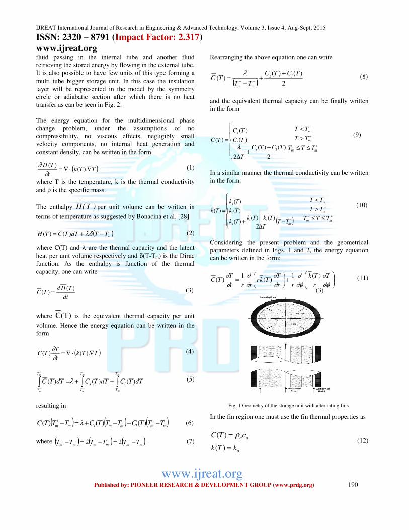
Fig. 1 shows a section of the finned tubes system, the flow
passage of the heat transfer fluids and the external
insulation layer. As can be seen the internal tube has
external fins while the external tube is fitted with internal
fins. The space between the two tubes is occupied by the
PCM. By this arrangement it is possible to enhance the
heat transfer charging and discharging processes. If it is
required to charge and discharge the unit this will be
possible by arrangement of a system of valves to allow one
IJREAT International Journal of Research in Engineering & Advanced Technology, Volume 3, Issue 4, Aug-Sept, 2015 ISSN: 2320 – 8791 (Impact Factor: 2.317)
www.ijreat.org
www.ijreat.org Published by: PIONEER RESEARCH & DEVELOPMENT GROUP (www.prdg.org) 190
fluid passing in the internal tube and another fluid
retrieving the stored energy by flowing in the external tube.
It is also possible to have few units of this type forming a
multi tube bigger storage unit. In this case the insulation
layer will be represented in the model by the symmetry
circle or adiabatic section after which there is no heat
transfer as can be seen in Fig. 2.
The energy equation for the multidimensional phase
change problem, under the assumptions of no
compressibility, no viscous effects, negligibly small
velocity components, no internal heat generation and
constant density, can be written in the form
( )TTkt
TH∇⋅∇= ).(
)(
∂
∂ (1)
where T is the temperature, k is the thermal conductivity
and ρ is the specific mass.
The enthalpy )T(H_
per unit volume can be written in
terms of temperature as suggested by Bonacina et al. [28]
( )mTTdTTCTH −+= λδ)()( (2)
where C(T) and λ are the thermal capacity and the latent
heat per unit volume respectively and δ(T-Tm) is the Dirac
function. As the enthalpy is function of the thermal
capacity, one can write
dt
THdTC
)()( = (3) (3)
where )T(C is the equivalent thermal capacity per unit
volume. Hence the energy equation can be written in the
form
( )TTkt
TTC ∇⋅∇= ).()(
∂
∂ (4)
∫∫∫+
−
+
−
++=m
m
m
m
m
m
T
T
l
T
T
s
T
T
dTTCdTTCdTTC )()()( λ (5)
resulting in
( ) ( ) ( )mmlmmsmm TTTCTTTCTTTC −+−+=− +−−+ )()()( λ (6)
where ( ) ( ) ( )mmmmmm TTTTTT −=−=− +−−+ 22 (7)
Rearranging the above equation one can write
( ) 2
)()()(
TCTC
TTTC ls
mm
++
−=
−+
λ (8)
and the equivalent thermal capacity can be finally written
in the form
++
∆
=
2
)()(
2
)(
)(
)(
TCTC
T
TC
TC
TC
ls
l
s
λ +−
+
−
≤≤
>
<
mm
m
m
TTT
TT
TT (9)
In a similar manner the thermal conductivity can be written
in the form:
( )
−∆
−+
=
−m
sls
l
s
TTT
TkTkTk
Tk
Tk
Tk
2
)()()(
)(
)(
)(
+−
+
−
≤≤
>
<
mm
m
m
TTT
TT
TT (10)
Considering the present problem and the geometrical
parameters defined in Figs. 1 and 2, the energy equation
can be written in the form:
+
=
∂φ
∂
∂φ
∂
∂
∂
∂
∂
∂
∂ T
r
Tk
rr
TTkr
rrt
TTC
)(1)(
1)( (11)
Fig. 1 Geometry of the storage unit with alternating fins.
In the fin region one must use the fin thermal properties as
a
aa
kTk
cTC
=
=
)(
)( ρ (12)
IJREAT International Journal of Research in Engineering & Advanced Technology, Volume 3, Issue 4, Aug-Sept, 2015 ISSN: 2320 – 8791 (Impact Factor: 2.317)
www.ijreat.org
www.ijreat.org Published by: PIONEER RESEARCH & DEVELOPMENT GROUP (www.prdg.org) 191
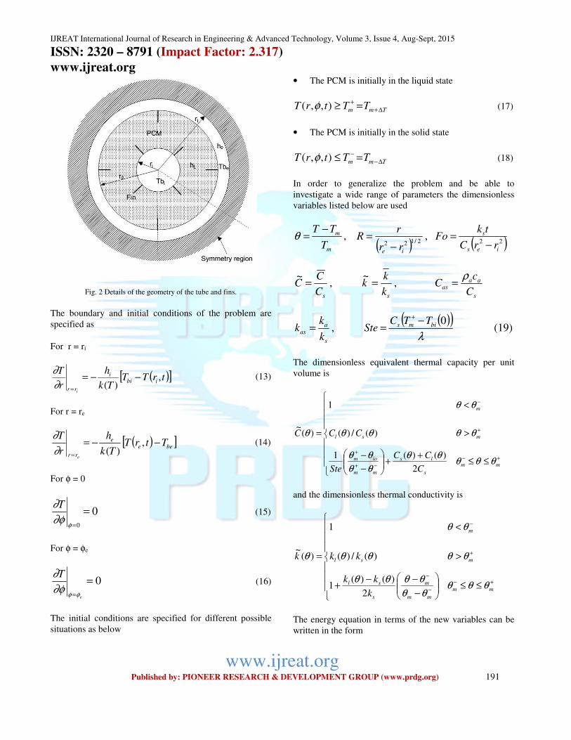
Fig. 2 Details of the geometry of the tube and fins.
The boundary and initial conditions of the problem are
specified as
For r = ri
( )[ ]trTTTk
h
r
Tibi
i
rr i
,)(
−−==∂
∂ (13)
For r = re
( )[ ]beee
rr
TtrTTk
h
r
T
e
−−==
,)(∂
∂ (14)
For φ = 0
00
==φ
∂φ
∂T (15)
For φ = φe
0== e
T
φφ∂φ
∂ (16)
The initial conditions are specified for different possible
situations as below
• The PCM is initially in the liquid state
Tmm TTtrT ∆++ =≥),,( φ (17)
• The PCM is initially in the solid state
Tmm TTtrT ∆−− =≤),,( φ (18)
In order to generalize the problem and be able to
investigate a wide range of parameters the dimensionless
variables listed below are used
m
m
T
TT −=θ ,
( ) 2/122
ie rr
rR
−= , ( )22
ies
s
rrC
tkFo
−=
sC
CC =~
, sk
kk =~
, s
aaas
C
cC
ρ=
s
aas
k
kk = ,
( )( )λ
0bims TTCSte
−=
+
(19)
The dimensionless equivalent thermal capacity per unit
volume is
≤≤+
+
−
−
>
<
=
+−
−+
+
+
−
mm
s
ls
mm
iom
msl
m
C
CC
Ste
CCC
θθθθθ
θθ
θθ
θθθθ
θθ
θ
2
)()(1
)(/)(
1
)(~
and the dimensionless thermal conductivity is
≤≤
−
−−+
>
<
=
+−
−
−
+
−
mm
mm
m
s
sl
msl
m
k
kk
kkk
θθθθθ
θθθθ
θθθθ
θθ
θ
2
)()(1
)(/)(
1
)(~
The energy equation in terms of the new variables can be
written in the form
IJREAT International Journal of Research in Engineering & Advanced Technology, Volume 3, Issue 4, Aug-Sept, 2015 ISSN: 2320 – 8791 (Impact Factor: 2.317)
www.ijreat.org
www.ijreat.org Published by: PIONEER RESEARCH & DEVELOPMENT GROUP (www.prdg.org) 192
+
=
∂φ
∂θθ
∂φ
∂
∂
∂θθ
∂
∂
∂
∂θθ
R
k
RRkR
RRFoC
)(~
1)(
~1)(
~ (20)
The boundary conditions in their dimensionless form are
presented as below
[ ]0
11
i
i
RR R
Bi
Rθθ
∂
∂θ−=
=
(21a)
[ ]0
22
ee
RR R
Bi
Rθθ
∂
∂θ−−=
=
(21b)
00
==φ
∂φ
∂θ (21c)
0== eφφ∂φ
∂θ (21d)
where k
rhBi ii
i = , k
rhBi ee
e = ,
( ) 2/1221
ie
i
rr
rR
−= ,
( ) 2/1222
ie
ei
rr
rR
−=
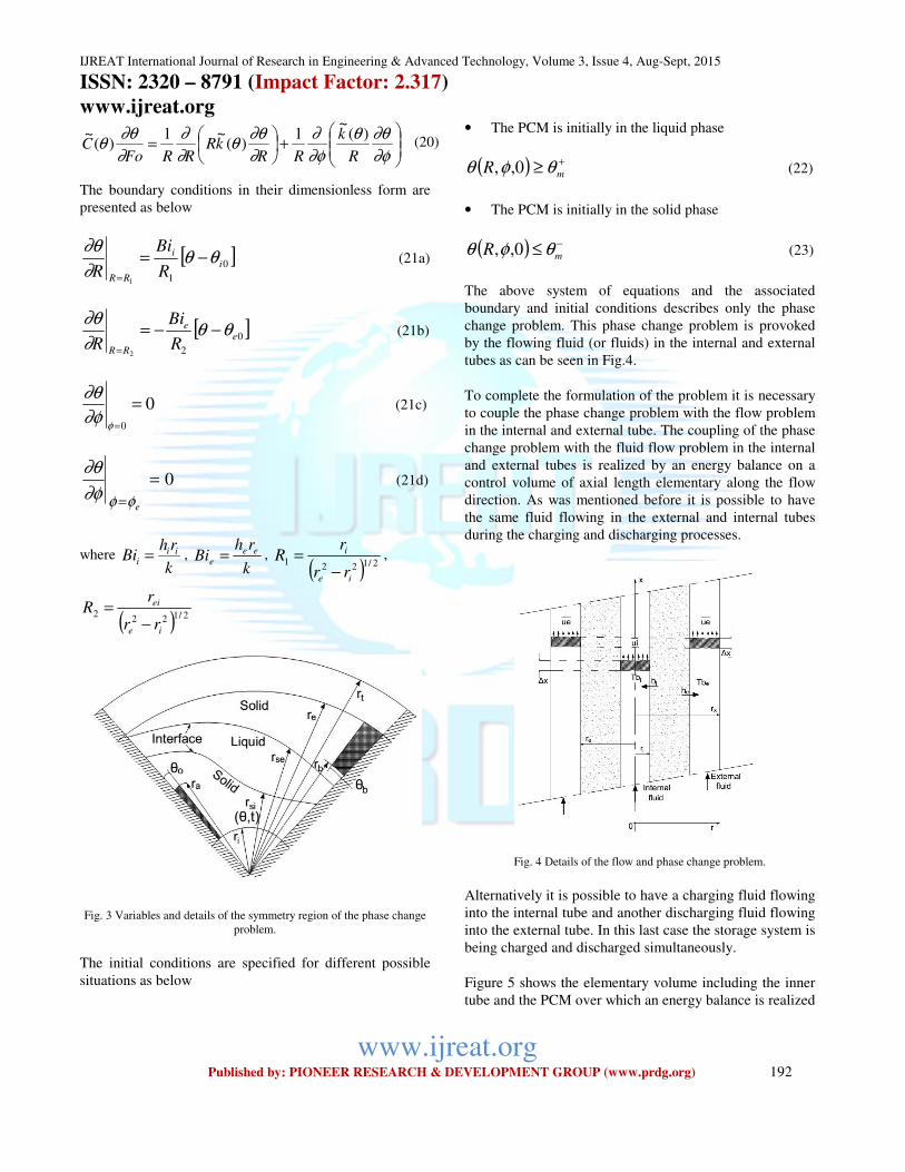
Fig. 3 Variables and details of the symmetry region of the phase change
problem.
The initial conditions are specified for different possible
situations as below
• The PCM is initially in the liquid phase
( ) +≥ mR θφθ 0,, (22)
• The PCM is initially in the solid phase
( ) −≤ mR θφθ 0,, (23)
The above system of equations and the associated
boundary and initial conditions describes only the phase
change problem. This phase change problem is provoked
by the flowing fluid (or fluids) in the internal and external
tubes as can be seen in Fig.4.
To complete the formulation of the problem it is necessary
to couple the phase change problem with the flow problem
in the internal and external tube. The coupling of the phase
change problem with the fluid flow problem in the internal
and external tubes is realized by an energy balance on a
control volume of axial length elementary along the flow
direction. As was mentioned before it is possible to have
the same fluid flowing in the external and internal tubes
during the charging and discharging processes.
Fig. 4 Details of the flow and phase change problem.
Alternatively it is possible to have a charging fluid flowing
into the internal tube and another discharging fluid flowing
into the external tube. In this last case the storage system is
being charged and discharged simultaneously.
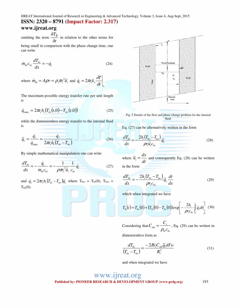
Figure 5 shows the elementary volume including the inner
tube and the PCM over which an energy balance is realized
IJREAT International Journal of Research in Engineering & Advanced Technology, Volume 3, Issue 4, Aug-Sept, 2015 ISSN: 2320 – 8791 (Impact Factor: 2.317)
www.ijreat.org
www.ijreat.org Published by: PIONEER RESEARCH & DEVELOPMENT GROUP (www.prdg.org) 193
omitting the term t
Tb
∂
∂ in relation to the other terms for
being small in comparison with the phase change time, one
can write
i
bi
bibi qdx
dTcm && −= (24)
where iiibi urvAm2πρρ ==& and
ir
siir
Tkrq
∂
∂π2=&
The maximum possible energy transfer rate per unit length
is
( ) ( )( )0,0,2max tTtThrq bebiii −= π& (25)
while the dimensionless energy transfer to the internal fluid
is
( )bebiii
ii
iTThr
q
q
−==
π2max
&
&
& (26)
By simple mathematical manipulation one can write
i
biiibibi
ibi qcurcm
q
dx
dT&
&
& 112ρπ
−=−= (27)
and ( ) ibebiiii qTThrq −= π2& where Tbio = Tbi(0), Tbeo =
Tbe(0).
Fig. 5 Details of the flow and phase change problem for the internal
fluid.
Eq. (27) can be alternatively written in the form
( )i
biii
bebiibi qcur
TTh
dx
dT
ρ
−−=
2 (28)
where dt
dxui = and consequently Eq. (28) can be written
in the form
( )dx
dtq
cr
TTh
dx
dTi
bii
bebiibi
ρ
−−=
2 (29)
which when integrated we have
( ) ( ) ( ) ( )( )
−−+= ∫
t
i
bii
ibebibebi dtq
cr
hTTTtT
0
2exp000
ρ (30)
Considering that
bibi
ssbi
c
CC
ρ= , Eq. (29) can be written in
dimensionless form as
( ) 2
1
2
R
dFoqCBi
TT
dT isbii
bebi
bi −=
− (31)
and when integrated we have
IJREAT International Journal of Research in Engineering & Advanced Technology, Volume 3, Issue 4, Aug-Sept, 2015 ISSN: 2320 – 8791 (Impact Factor: 2.317)
www.ijreat.org
www.ijreat.org Published by: PIONEER RESEARCH & DEVELOPMENT GROUP (www.prdg.org) 194
( ) ( )
−−+= ∫
Fo
isbii
eiei dFoqR
CBiFo
0
2
1
000
2expθθθθ (32)
Where ( ) ( )
m
mbii
T
TtTFo
−=θ , ( )
( )
m
mbi
iiT
TT −==
000 θθ ,
( )( )
m
mbe
eeT
TT −==
000 θθ
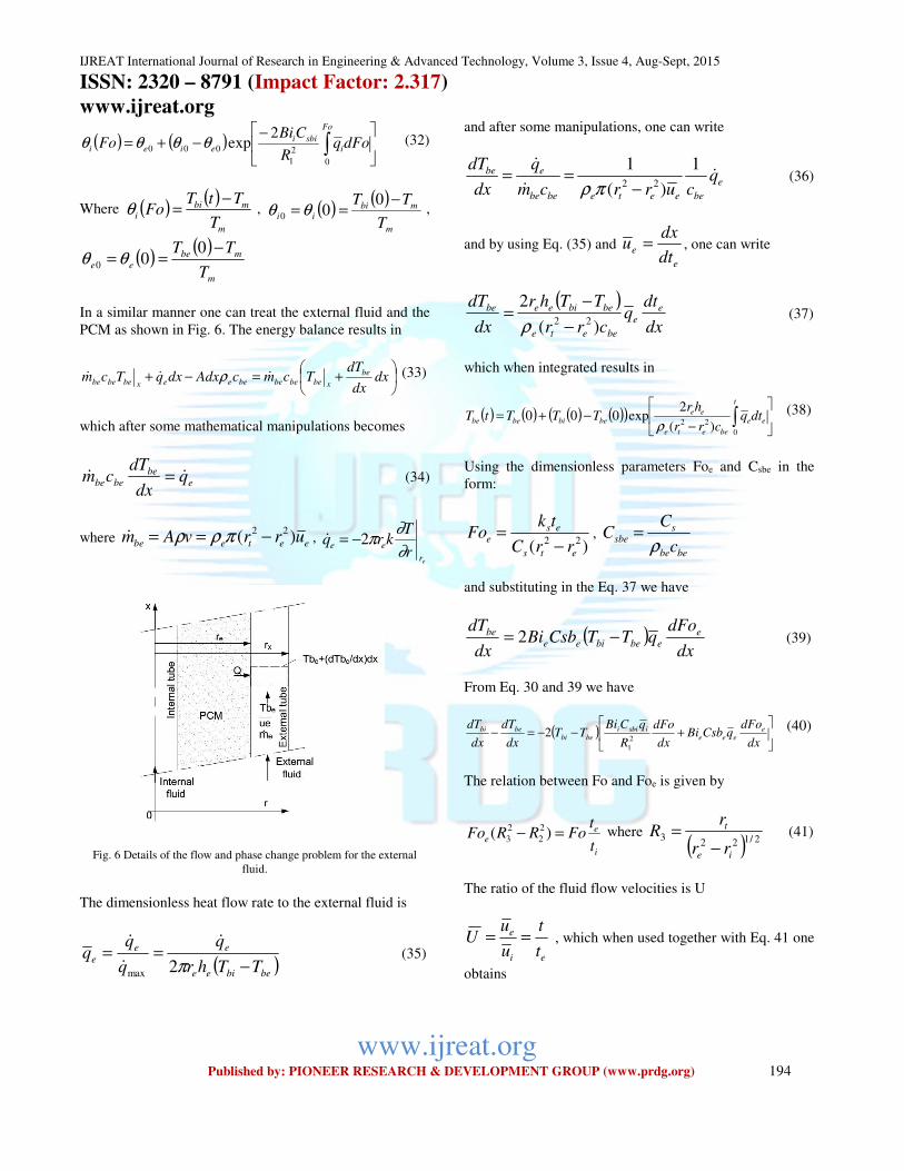
In a similar manner one can treat the external fluid and the
PCM as shown in Fig. 6. The energy balance results in
+=−+ dx
dx
dTTcmcAdxdxqTcm be
xbebebebeeexbebebe&&& ρ (33)
which after some mathematical manipulations becomes
e
be
bebe qdx
dTcm && = (34)
where eetebe urrvAm )(22 −== πρρ& ,
er
eer
Tkrq
∂
∂π2−=&
Fig. 6 Details of the flow and phase change problem for the external
fluid.
The dimensionless heat flow rate to the external fluid is
( )bebiee
ee
eTThr
q
q
−==
π2max
&
&
& (35)
and after some manipulations, one can write
e
beeetebebe
ebe qcurrcm
q
dx
dT&
&
& 1
)(
122 −
==πρ
(36)
and by using Eq. (35) and
e
edt
dxu = , one can write
( )dx
dtq
crr
TThr
dx
dT e
e
beete
bebieebe
)(
222 −
−=
ρ (37)
which when integrated results in
( ) ( ) ( ) ( )( )
−−+= ∫
t
ee
beete
eebebibebe dtq
crr
hrTTTtT
0
22 )(
2exp000
ρ (38)
Using the dimensionless parameters Foe and Csbe in the
form:
)( 22
ets
ese
rrC
tkFo
−= ,
bebe
ssbe
c
CC
ρ=
and substituting in the Eq. 37 we have
( )dx
dFoqTTCsbBi
dx
dT eebebiee
be −= 2 (39)
From Eq. 30 and 39 we have
( )
+−−=−
dx
dFoqCsbBi
dx
dFo
R
qCBiTT
dx
dT
dx
dT eeee
isbiibebi
bebi
2
1
2 (40)
The relation between Fo and Foe is given by
i
ee
t
tFoRRFo =− )( 2
2
2
3 where
( ) 2/1223
ie
t
rr
rR
−= (41)
The ratio of the fluid flow velocities is U
ei
e
t
t
u
uU == , which when used together with Eq. 41 one
obtains
IJREAT International Journal of Research in Engineering & Advanced Technology, Volume 3, Issue 4, Aug-Sept, 2015 ISSN: 2320 – 8791 (Impact Factor: 2.317)
www.ijreat.org
www.ijreat.org Published by: PIONEER RESEARCH & DEVELOPMENT GROUP (www.prdg.org) 195
FoURRFoe =− )( 2
2
2
3 (42)
and
edFoURRdFo )( 2
2
2
3 −=
Eq. (40) can be written in terms of dFo as
( )( )
−+−−=−
dx
dFo
RRU
qCsbBi
dx
dFo
R
qCBiTT
dx
dT
dx
dT eeeisbiibebi
bebi
2
2
2
3
2
1
2
which can be arranged in the form
( )( ) ( ) dx
dFo
RRU
qCsbBi
R
qCBi
TT
TTd eeeisbii
bebi
bebi
−+−=
−
−2
2
2
3
2
1
2 (43)
Integration of Eq. (43) yields
( ) ( ) ( ) ( )( )( )
−+−−−= ∫
Fo
eeeisbiieiie
dx
dFo
RRU
qCsbBi
R
qCBiFoFo
0
2
2
2
3
2
1
2exp00 θθθθ (44)
In order to determine the heat absorbed or liberated by the
PCM, one uses Eqs. 32 and 44 to obtain
( ) ( ) ( )i
i
rbebiibebiii
r
i
bebiii
ii
ir
T
TTh
k
TThr
r
Tkr
TThr
q
q
∂
∂
π
∂
∂π
π −=
−=
−==
2
2
2max
&
&
&
which in the dimensionless form becomes
( )100
1 1
Reii
iRBi
Rq
∂
∂θ
θθ −=
and by the Eq. 21a, we have
( )( )
( )( )00
00
100
1 1
ei
i
i
i
eii
iR
Bi
Bi
Rq
θθ
θθθθ
θθ −
−=−
−= (45)
and for the external fluid by means of Eq. 21b we have
( )( )
( )( )00
00
200
2 1
ei
e
e
e
eie
eR
Bi
Bi
Rq
θθ
θθθθ
θθ −
−=−
−= (46)
To derive the equations for the effectiveness and the NTU
we followed the procedure of Shamsundar and Srimivesan
[29] in which they related the NTU to the solidified mass
fraction, F, through an energy balance between the fluid
element and the PCM. For the internal fluid, the equation
resulting from the energy balance can be written as
( ) ibebiiiibi
bibi qTThrqdx
dTcm −−=−= π2&& (47)
Writing the heat flow rate leaving or entering the storage in
terms of the fraction of solidified/melt mass,
( ) ( )dt
dFrrLqTThrq iebibebiii
222 −=−= πρπ&
where L is the latent heat and F is the fraction of
solidified/melt mass.
Hence, Eq. 47 can be written in the form
( )dt
dFrrLq
dx
dTcm iebi
bibibi
22 −−=−= πρ&&
which can be rearranged in the form
( )( ) i
ieb
bebii qrrL
TThr
dt
dF22
2
−
−=
πρ
π (48)
Define a new dimensionless variable τ as
( )( ) FoStet
rrL
TTk
ieb
bims .22
=−
−=
+
ρτ . Eq. (48) can be written as
( )( )
( )( ) i
em
ei
ii
bim
bebi
i qBiqTT
TTBi
d
dF
0
0022θθ
θθ
τ −
−=
−
−=
++ (49)
If we multiply and divide both sides of Eq. 48 by k and
rearranged it and integrating it we have
( ) ∫∫ =−
−F
s
t
bi
ieb
sbibi dFkdtdx
dT
rrL
kcm
00
22π
ρ
&
or
( ) Fkdx
d
TT
dTcm s
bim
bi
bibi πττ
=−
− ∫ +
0
& (50)
As the time for phase change is much more than the time
for fluid flow, the temperature of the internal fluid Tbi
IJREAT International Journal of Research in Engineering & Advanced Technology, Volume 3, Issue 4, Aug-Sept, 2015 ISSN: 2320 – 8791 (Impact Factor: 2.317)
www.ijreat.org
www.ijreat.org Published by: PIONEER RESEARCH & DEVELOPMENT GROUP (www.prdg.org) 196
changes with the time and the axial position and also the
heat flux iq& and F change with τ, Eq. 50 can be written as
Fkdx
dcm sbibi π
τ=& which can be rearranged in the form
( )( )
dxcm
kBi
Fq
dF
bibi
si
iei
em
&
π
θθ
θθ 2
00
0 =−
−+
which when integrated yields
( )( ) ∫∫ ==
−
−+ Z
bibi
si
bibi
si
F
F iei
em Zcm
kBidx
cm
kBi
Fq
dFZ
000
0 22
0
&&
ππ
θθ
θθ
or
( )( ) i
F
F iei
em NTUFq
dFZ
=−
−∫
+
000
0
θθ
θθ (51)
The effectiveness can be written as
( )( )
( )( )00
0 1im
izm
imbibi
iizbibi
iTT
TT
TTcm
TTcm
−
−−=
−
−=
+
+
+&
&ε (52)
and following the work of [29], one can write
0
1F
FZi −=ε (53)
For the external fluid, one can write similar relations for
the NTUe and εe as
( )( ) e
F
F eei
em NTUFq
dFZ
=−
−∫
+
000
0
θθ
θθ (54)
0
1F
FZe −=ε (55)
3. Numerical Solution
The numerical solution is realized by the discretization of
the governing equation and the boundary and initial
conditions as described by Patankar [30]. In this method
the domain is divided into a number of control volumes
each one is associated with a nodal point. The
discretization is obtained by integration over the control
volume and hence each control volume satisfies the
conservation principle and consequently all the domain is
satisfied, transforming the differential equation into a
system of algebraic equations. Numerical tests were
realized in order to optimize the number of points used in
the numerical solution. It was found that an axial grid of 10
points, a radial grid of 30 points and time step of 0.01s are
sufficient to satisfy the convergence criterion.
4. Results and Discussion
In order to validate the model and the numerical method
comparisons between the present results and available
numerical and experimental data were realized. Initially,
the present model was adapted for the case of finless tube
and the predicted results were compared with Sparrow et
al. [31, 32] and also with the experimental results. The
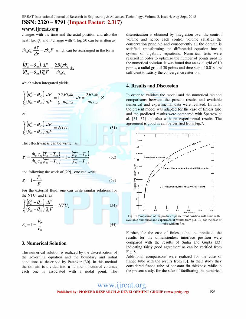
agreement is good as can be verified from Fig.7.
Fig. 7 Comparison of the predicted phase front position with time with
available numerical and experimental results from [31, 32] for the case of
tube without fins.
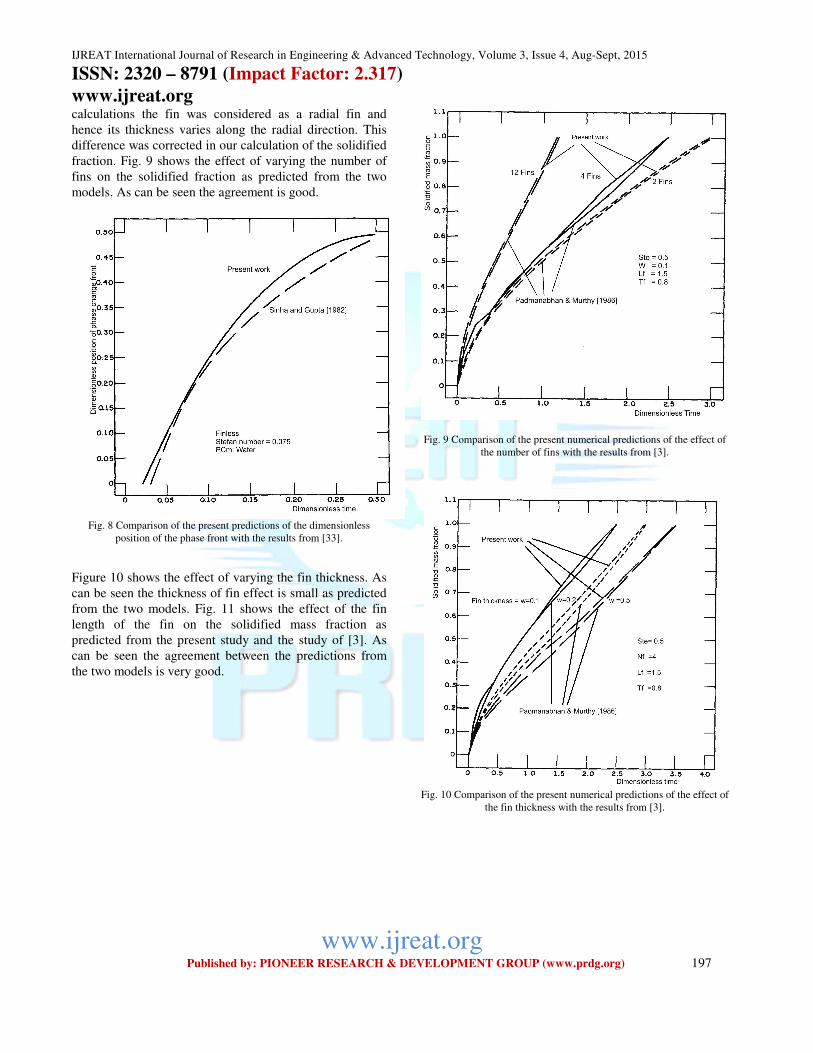
Further, for the case of finless tube, the predicted the
results for the dimensionless interface position were
compared with the results of Sinha and Gupta [33]
indicating fairly good agreement as can be verified from
Fig. 8.
Additional comparisons were realized for the case of
finned tube with the results from [3]. In their study they
considered finned tube of constant fin thickness while in
the present study, for the sake of facilitating the numerical
IJREAT International Journal of Research in Engineering & Advanced Technology, Volume 3, Issue 4, Aug-Sept, 2015 ISSN: 2320 – 8791 (Impact Factor: 2.317)
www.ijreat.org
www.ijreat.org Published by: PIONEER RESEARCH & DEVELOPMENT GROUP (www.prdg.org) 197
calculations the fin was considered as a radial fin and
hence its thickness varies along the radial direction. This
difference was corrected in our calculation of the solidified
fraction. Fig. 9 shows the effect of varying the number of
fins on the solidified fraction as predicted from the two
models. As can be seen the agreement is good.
Fig. 8 Comparison of the present predictions of the dimensionless
position of the phase front with the results from [33].
Figure 10 shows the effect of varying the fin thickness. As
can be seen the thickness of fin effect is small as predicted
from the two models. Fig. 11 shows the effect of the fin
length of the fin on the solidified mass fraction as
predicted from the present study and the study of [3]. As
can be seen the agreement between the predictions from
the two models is very good.
Fig. 9 Comparison of the present numerical predictions of the effect of
the number of fins with the results from [3].
Fig. 10 Comparison of the present numerical predictions of the effect of
the fin thickness with the results from [3].
IJREAT International Journal of Research in Engineering & Advanced Technology, Volume 3, Issue 4, Aug-Sept, 2015 ISSN: 2320 – 8791 (Impact Factor: 2.317)
www.ijreat.org
www.ijreat.org Published by: PIONEER RESEARCH & DEVELOPMENT GROUP (www.prdg.org) 198
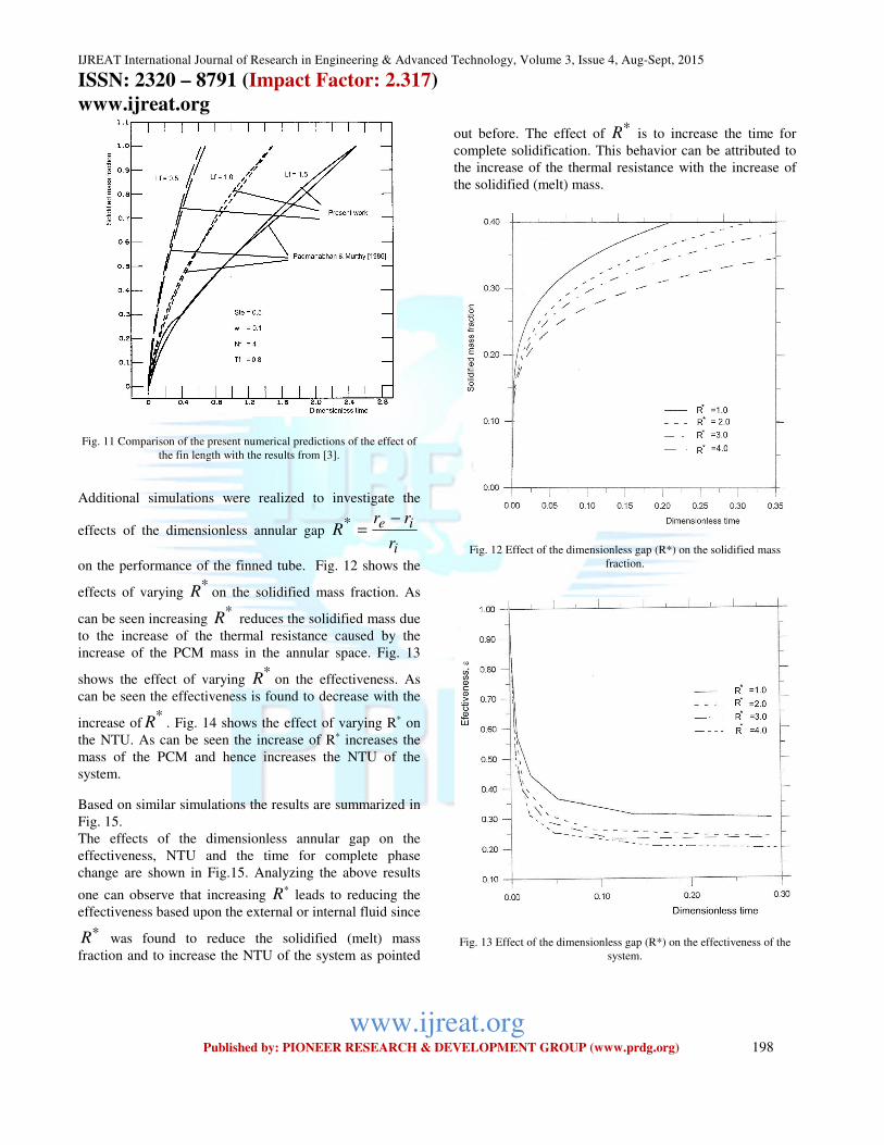
Fig. 11 Comparison of the present numerical predictions of the effect of
the fin length with the results from [3].
Additional simulations were realized to investigate the
effects of the dimensionless annular gap
i
ie*
r
rrR
−=
on the performance of the finned tube. Fig. 12 shows the
effects of varying *R on the solidified mass fraction. As
can be seen increasing *R reduces the solidified mass due
to the increase of the thermal resistance caused by the
increase of the PCM mass in the annular space. Fig. 13
shows the effect of varying *R on the effectiveness. As
can be seen the effectiveness is found to decrease with the
increase of*R . Fig. 14 shows the effect of varying R* on
the NTU. As can be seen the increase of R* increases the
mass of the PCM and hence increases the NTU of the
system.
Based on similar simulations the results are summarized in
Fig. 15.
The effects of the dimensionless annular gap on the
effectiveness, NTU and the time for complete phase
change are shown in Fig.15. Analyzing the above results
one can observe that increasing ∗R leads to reducing the
effectiveness based upon the external or internal fluid since
∗R was found to reduce the solidified (melt) mass
fraction and to increase the NTU of the system as pointed
out before. The effect of ∗R is to increase the time for
complete solidification. This behavior can be attributed to
the increase of the thermal resistance with the increase of
the solidified (melt) mass.
Fig. 12 Effect of the dimensionless gap (R*) on the solidified mass
fraction.
Fig. 13 Effect of the dimensionless gap (R*) on the effectiveness of the
system.
IJREAT International Journal of Research in Engineering & Advanced Technology, Volume 3, Issue 4, Aug-Sept, 2015 ISSN: 2320 – 8791 (Impact Factor: 2.317)
www.ijreat.org
www.ijreat.org Published by: PIONEER RESEARCH & DEVELOPMENT GROUP (www.prdg.org) 199
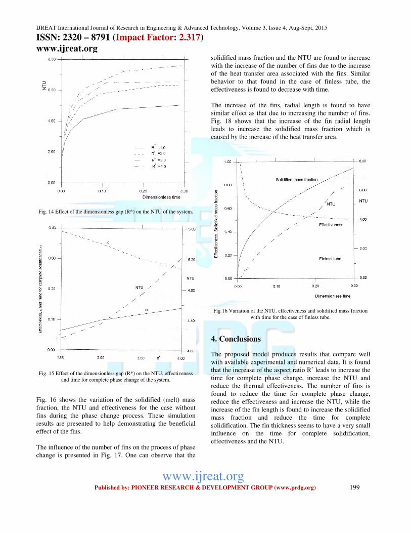
Fig. 14 Effect of the dimensionless gap (R*) on the NTU of the system.
Fig. 15 Effect of the dimensionless gap (R*) on the NTU, effectiveness
and time for complete phase change of the system.
Fig. 16 shows the variation of the solidified (melt) mass
fraction, the NTU and effectiveness for the case without
fins during the phase change process. These simulation
results are presented to help demonstrating the beneficial
effect of the fins.
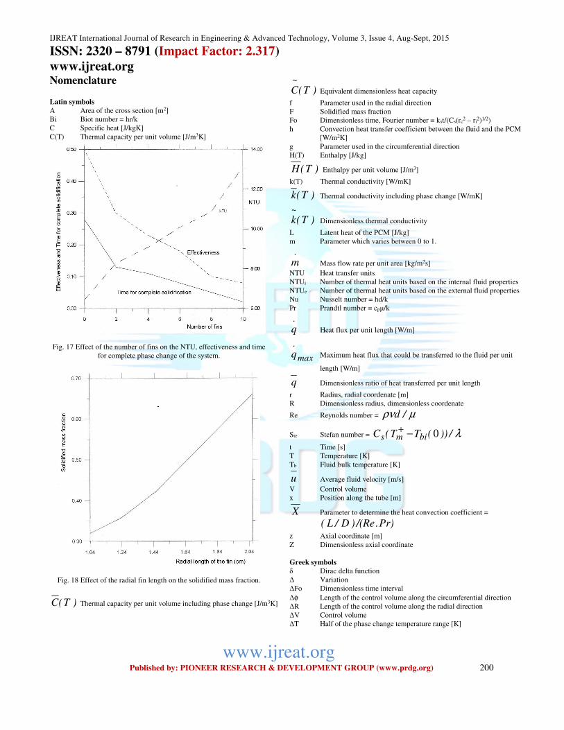
The influence of the number of fins on the process of phase
change is presented in Fig. 17. One can observe that the
solidified mass fraction and the NTU are found to increase
with the increase of the number of fins due to the increase
of the heat transfer area associated with the fins. Similar
behavior to that found in the case of finless tube, the
effectiveness is found to decrease with time.
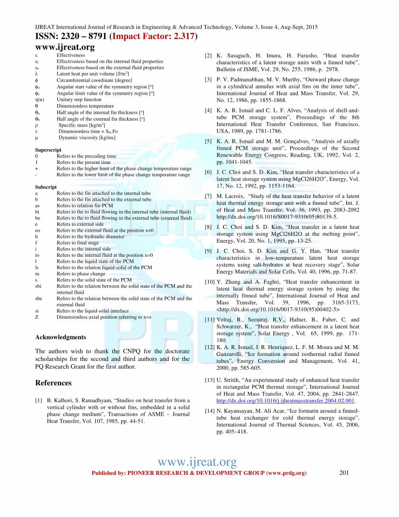
The increase of the fins, radial length is found to have
similar effect as that due to increasing the number of fins.
Fig. 18 shows that the increase of the fin radial length
leads to increase the solidified mass fraction which is
caused by the increase of the heat transfer area.
Fig 16 Variation of the NTU, effectiveness and solidified mass fraction
with time for the case of finless tube.
4. Conclusions
The proposed model produces results that compare well
with available experimental and numerical data. It is found
that the increase of the aspect ratio R* leads to increase the
time for complete phase change, increase the NTU and
reduce the thermal effectiveness. The number of fins is
found to reduce the time for complete phase change,
reduce the effectiveness and increase the NTU, while the
increase of the fin length is found to increase the solidified
mass fraction and reduce the time for complete
solidification. The fin thickness seems to have a very small
influence on the time for complete solidification,
effectiveness and the NTU.
IJREAT International Journal of Research in Engineering & Advanced Technology, Volume 3, Issue 4, Aug-Sept, 2015 ISSN: 2320 – 8791 (Impact Factor: 2.317)
www.ijreat.org
www.ijreat.org Published by: PIONEER RESEARCH & DEVELOPMENT GROUP (www.prdg.org) 200
Nomenclature Latin symbols
A Area of the cross section [m2]
Bi Biot number = hr/k
C Specific heat [J/kgK]
C(T) Thermal capacity per unit volume [J/m3K]
Fig. 17 Effect of the number of fins on the NTU, effectiveness and time
for complete phase change of the system.
Fig. 18 Effect of the radial fin length on the solidified mass fraction.
)T(C Thermal capacity per unit volume including phase change [J/m3K]
)T(C~
Equivalent dimensionless heat capacity
f Parameter used in the radial direction
F Solidified mass fraction
Fo Dimensionless time, Fourier number = kst/(Cs(rc2 – ri
2)1/2)
h Convection heat transfer coefficient between the fluid and the PCM
[W/m2K]
g Parameter used in the circumferential direction
H(T) Enthalpy [J/kg]
)T(H Enthalpy per unit volume [J/m3]
k(T) Thermal conductivity [W/mK]
)T(k Thermal conductivity including phase change [W/mK]
)T(k~
Dimensionless thermal conductivity
L Latent heat of the PCM [J/kg]
m Parameter which varies between 0 to 1.
.
m Mass flow rate per unit area [kg/m2s]
NTU Heat transfer units
NTUi Number of thermal heat units based on the internal fluid properties
NTUe Number of thermal heat units based on the external fluid properties
Nu Nusselt number = hd/k
Pr Prandtl number = cpμ/k
.
q Heat flux per unit length [W/m]
max
.
q Maximum heat flux that could be transferred to the fluid per unit
length [W/m]
q Dimensionless ratio of heat transferred per unit length
r Radius, radial coordenate [m]
R Dimensionless radius, dimensionless coordenate
Re Reynolds number = µρν /d
Ste Stefan number = λ/))(TT(C bims 0−+
t Time [s]
T Temperature [K]
Tb Fluid bulk temperature [K]
u Average fluid velocity [m/s]
V Control volume
x Position along the tube [m]
X Parameter to determine the heat convection coefficient =
Pr)./(Re)D/L(
z Axial coordinate [m]
Z Dimensionless axial coordinate
Greek symbols
δ Dirac delta function
Δ Variation
ΔFo Dimensionless time interval
Δφ Length of the control volume along the circumferential direction
ΔR Length of the control volume along the radial direction
ΔV Control volume
ΔT Half of the phase change temperature range [K]
IJREAT International Journal of Research in Engineering & Advanced Technology, Volume 3, Issue 4, Aug-Sept, 2015 ISSN: 2320 – 8791 (Impact Factor: 2.317)
www.ijreat.org
www.ijreat.org Published by: PIONEER RESEARCH & DEVELOPMENT GROUP (www.prdg.org) 201
ε Effectiveness
εi Effectiveness based on the internal fluid properties
εe Effectiveness based on the external fluid properties
λ Latent heat per unit volume [J/m3]
φ Circumferential coordinate [degree]
φo Angular start value of the symmetry region [o]
φe Angular limit value of the symmetry region [o]
η(u) Unitary step function
θ Dimensionless temperature
θa Half angle of the internal fin thickness [o]
θb Half angle of the external fin thickness [o]
ρ Specific mass [kg/m3]
τ Dimensionless time = Ste.Fo
μ Dynamic viscosity [kg/ms]
Superscript
0 Refers to the preceding time
1 Refers to the present time
+ Refers to the higher limit of the phase change temperature range
- Refers to the lower limit of the phase change temperature range
Subscript
a Refers to the fin attached to the internal tube
b Refers to the fin attached to the external tube
as Refers to relation fin-PCM
bi Refers to the to fluid flowing in the internal tube (internal fluid)
be Refers to the to fluid flowing in the external tube (external fluid)
e Refers to external side
eo Refers to the external fluid at the position x=0
h Refers to the hydraulic diameter
f Refers to final stage
i Refers to the internal side
io Refers to the internal fluid at the position x=0
l Refers to the liquid state of the PCM
ls Refers to the relation liquid-solid of the PCM
m Refers to phase change
s Refers to the solid state of the PCM
sbi Refers to the relation between the solid state of the PCM and the
internal fluid
sbe Refers to the relation between the solid state of the PCM and the
external fluid
si Refers to the liquid-solid interface
Z Dimensionless axial position referring to x=z
Acknowledgments
The authors wish to thank the CNPQ for the doctorate
scholarships for the second and third authors and for the
PQ Research Grant for the first author.
References
[1] B. Kalhori, S. Ramadhyam, “Studies on heat transfer from a
vertical cylinder with or without fins, embedded in a solid
phase change medium”, Transactions of ASME – Journal
Heat Transfer, Vol. 107, 1985, pp. 44-51.
[2] K. Sasaguch, H. Imura, H. Furusho, “Heat transfer
characteristics of a latent storage units with a finned tube”,
Bulletin of JSME, Vol. 29, No. 255, 1986, p. 2978.
[3] P. V. Padmanabhan, M. V. Murthy, “Outward phase change
in a cylindrical annulus with axial fins on the inner tube”,
International Journal of Heat and Mass Transfer, Vol. 29,
No. 12, 1986, pp. 1855-1868.
[4] K. A. R. Ismail and C. L. F. Alves, “Analysis of shell-and-
tube PCM storage system”, Proceedings of the 8th
International Heat Transfer Conference, San Francisco,
USA, 1989, pp. 1781-1786.
[5] K. A. R. Ismail and M. M. Gonçalves, “Analysis of axially
finned PCM storage unit”, Proceedings of the Second
Renewable Energy Congress, Reading, UK, 1992, Vol. 2,
pp. 1041-1045.
[6] J. C. Choi and S. D. Kim, “Heat transfer characteristics of a
latent heat storage system using MgCl26H2O”, Energy, Vol.
17, No. 12, 1992, pp. 1153-1164.
[7] M. Lacroix, “Study of the heat transfer behavior of a latent
heat thermal energy storage unit with a finned tube”, Int. J.
of Heat and Mass Transfer, Vol. 36, 1993, pp. 2083-2092
http://dx.doi.org/10.1016/S0017-9310(05)80139-5.
[8] J. C. Choi and S. D. Kim, “Heat transfer in a latent heat
storage system using MgCl26H2O at the melting point”,
Energy, Vol. 20, No. 1, 1995, pp. 13-25.
[9] J. C. Choi, S. D. Kim and G. Y. Han, “Heat transfer
characteristics in low-temperature latent heat storage
systems using salt-hydrates at heat recovery stage”, Solar
Energy Materials and Solar Cells, Vol. 40, 1996, pp. 71-87.
[10] Y. Zhang and A. Faghri, “Heat transfer enhancement in
latent heat thermal energy storage system by using the
internally finned tube”, International Journal of Heat and
Mass Transfer, Vol. 39, 1996, pp. 3165-3173,
<http://dx.doi.org/10.1016/0017-9310(95)00402-5>
[11] Velraj, R., Seeniraj, R.V., Hafner, B., Faber, C. and
Schwarzer, K., “Heat transfer enhancement in a latent heat
storage system”, Solar Energy , Vol. 65, 1999, pp. 171-
180.
[12] K. A. R. Ismail, J. R. Henriquez, L. F. M. Moura and M. M.
Ganzarolli, “Ice formation around isothermal radial finned
tubes”, Energy Conversion and Management, Vol. 41,
2000, pp. 585-605.
[13] U. Stritih, “An experimental study of enhanced heat transfer
in rectangular PCM thermal storage”, International Journal
of Heat and Mass Transfer, Vol. 47, 2004, pp. 2841-2847.
http://dx.doi.org/10.1016/j.ijheatmasstransfer.2004.02.001.
[14] N. Kayansayan, M. Ali Acar, “Ice formatin around a finned-
tube heat exchanger for cold thermal energy storage”,
International Journal of Thermal Sciences, Vol. 45, 2006,
pp. 405–418.
IJREAT International Journal of Research in Engineering & Advanced Technology, Volume 3, Issue 4, Aug-Sept, 2015 ISSN: 2320 – 8791 (Impact Factor: 2.317)
www.ijreat.org
www.ijreat.org Published by: PIONEER RESEARCH & DEVELOPMENT GROUP (www.prdg.org) 202
[15] N. Yuksel, A. Avci and M. Kilicn, “A model for latent heat
energy storage systems”, Int. J. Energy Res., Vol. 30, 2006,
pp. 1146–1157.
[16] Anica Trp, “An experimental and numerical investigation of
heat transfer during technical grade paraffin melting and
solidification in a shell-and-tube latent thermal energy
storage unit”, Applied Thermal Engineering, Vol. 26, 2006,
pp. 1830–1839.
[17] A. Erek and M. A. Ezan, “Experimental and numerical
study on charging processes of an ice-on-coil thermal
energy storage system”, Int. J. Energy Res. Vol. 31, 2007,
pp. 158–176.
[18] J. Bony, S. Citherlet, “Numerical model and experimental
validation of heat storage with phase change materials”,
Energy and Buildings, Vol. 39, 2007, pp. 1065–1072.
[19] E. B. S. Mettawee, and G. M. R. Assassa, “Thermal
conductivity enhancement in a latent heat storage system”,
Solar Energy, Vol. 81, 2007, pp. 839-845,
http://dx.doi.org/10.1016/j.solener.2006.11.009.
[20] S. Wang, A. Faghri, T. L. Bergman, “A comprehensive
numerical model for melting with natural convection”,
International Journal of Heat and Mass Transfer, Vol. 53,
2010, pp. 1986–2000.
[21] F. Rosler and D. Bruggemann, “Shell-and-tube type latent
heat thermal energy storage: numerical analysis and
comparison with experiments”, Heat Mass Transfer, Vol.
47, 2011, pp. 1027–1033, DOI 10.1007/s00231-011-0866-
9
[22] M. J. Hosseini, A. A. Ranjbar , K. Sedighi, M. Rahimi, “A
combined experimental and computational study on the
melting behavior of a medium temperature phase change
storage material inside shell and tube heat exchanger”,
International Communications in Heat and Mass Transfer,
Vol. 39, 2012, pp. 1416–1424.
[23] H. Shokouhmand, B. Kamkari, “Numerical Simulation of
phase change thermal storage in finned double-pipe heat
exchanger”, Applied Mechanics and Materials, Vol. 232,
2012, pp. 742-746.
http://dx.doi.org/10.4028/www.scientific.net/AMM.232.742
[24] M. R. Anisur, M. H. Mahfuz, M. A. Kibria, R. Saidur, I. H.
S. C. Metselaara and T. M. I. Mahlia, “Curbing global
warming with phase change materials for energy storage”,
Renewable and Sustainable Energy Reviews, Vol. 18, 2013,
pp. 23–30.
[25] J. N. W. Chiu and V. Martin, “Multistage latent heat cold
thermal energy storage design analysis”, Applied Energy,
Vol. 112, 2013, pp. 1438–1445.
[26] B. Basal, A. Unal, “Numerical evaluation of triple
concentric-tube latent heat thermal energy storage”, Solar
Energy, Vol. 92, 2013, pp. 196-205.
http://dx.doi.org/10.1016/j.solener.2013.02.032
[27] A. A. Al-Abidi, S. Mat, K. Sopian, M. Y. Sulaiman, A. T.
Mohammad, “Experimental study of melting and
solidification of PCM in a triplex tube heat exchanger with
fins”, Energy and Buildings, Vol. 68, 2014, pp. 33-41,
http://dx.doi.org/10.1016/j.enbuild.2013.09.007.
[28] C. Bonacina, G. Comini, A. Fasano, M. Primicerio,
“Numerical solution of phase change problems”,
International Journal Heat and Mass Transfer, Vol.16, 1973,
pp. 1825-1832.
[29] N. Shamsundar, R. Srimivesan, “Effectiveness NTU charts
for heat recovery from latent heat storage units”, Journal
Solar Engineering, Vol. 192, 1980, pp. 263-271.
[30] S. V. Patankar, Numerical Heat Transfer and Fluid Flow,
Hemisphere Publishing Corporation, Washington, DC,
USA. 1980.
[31] E. M. Sparrow, S. Ramadhyani, S. V. Patankar, “Effect of
subcooling on cylindrical melting”, Transactions of ASME
– Journal Heat Transfer, Vol.100, 1978, pp. 395-402.
[32] E. M. Sparrow, J. W. Ramsey, R. G. Kemink, “Freezing
controlled by natural convection”. Transactions of ASME –
Journal Heat Transfer, Vol. 101, 1979, pp. 578-584.
[33] T. K. Sinha, J. P. Gupta, “Solidification in an annulus”,
International Journal of Heat and Mass Transfer, Vol. 25,
1982, pp. 1771-1773.