enhancement of solidification of pcm around finned tubes ... (part-2)/k06124963.pdf · enhancement...
TRANSCRIPT
IOSR Journal of Engineering (IOSRJEN) www.iosrjen.org
ISSN (e): 2250-3021, ISSN (p): 2278-8719
Vol. 06, Issue 01 (January. 2016), ||V2|| PP 49-63
International organization of Scientific Research 49 | P a g e
Enhancement of solidification of PCM around finned tubes:
modeling and validation
Kamal A. R. Ismail1, Priscilla D. da Silva
2, Fatima A. M. Lino
3
1,2,3 State University of Campinas, Faculty of Mechanical Engineering,Department of Energy, Mendeleiev street,
200, Postal Code 13083-860, Cidade Universitária “Zeferino Vaz”, Barão Geraldo, Campinas, SP, Brazil
Abstract: - Phase change materials (PCMs) are the most attractive thermal energy storage media due to their
reduced storage volume and isothermal behavior during charging and discharging processes. Their main
drawback is the slow thermal response due to the low thermal conductivity. Various methods for PCM thermal
conductivity enhancement have been investigated by many researchers. The present study has the objective of
investigating fins for enhancing thermal conductivity of PCM and meliorates their thermal performance. The
formulated model for the horizontal radial finned tube is based on pure conduction in the PCM and numerically
treated by finite difference and Alternating Direction Implicit (ADI) formulation. The numerical code is
optimized and the numerical predictions were validated against experimental results. Additional numerical and
experimental measurements were realized to investigate the effects of the cooling fluid temperature, its mass
flow rate, diameter, thickness and material of the fin on the interface velocity, solidified mass and the time for
complete solidification.
Keywords: - Finned tube, latent heat storage system, PCM, phase change, solidification, thermal conductivity
enhancement
I. INTRODUCTION Phase change materials (PCMs) are attractive as thermal energy storage media due to their high thermal
capacity and their isothermal behavior during the phase change processes compared with sensible heat storage
systems. However, latent heat storage technology is still not widely implemented in practical applications
because of the difficulty to find PCM that possesses high thermal conductivity, large latent heat, low super
cooling and good stability among other characteristics. Organic PCMs are good candidates but have slow
thermal response due to their low thermal conductivity. Therefore, effective enhancement methods for the
liquid–solid phase change are the key issue that limits their practical application in latent heat energy storage
technology. Some works are worth mentioning because they treated certain aspects of the phase change process
in the early developments stages as [1, 2, 3]. Henze and Humphrey [1] presented a simplified numerical model
based on a quasi-linear transient equation, which predicts the fraction of melted PCM, and the shape of the
liquid-solid interface as a function of time with sufficient accuracy for engineering purposes. Experimental
results were compared with model predictions, and fairly good agreement was found. On the other hand,
Padmanabhan and Murthy [2] presented a numerical study for the phase change process occurring in a
cylindrical annulus in which rectangular, uniformly spaced axial fins, spanning the annulus are attached to the
inner isothermal tube. The time-wise evolution of the interface profile, phase-change fraction and energy
stored/discharged were presented. Later, Ismail et al. [3] presented the results of a numerical and experimental
investigation on finned tubes. The model was based upon the pure conduction, the enthalpy formulation
approach and the control volume method. Their results were validated against available results and their own
experimental measurements. The number of fins, fin length, fin thickness, the degree of super heat and the
aspect ratio of the annular spacing were found to influence the time for complete solidification, solidified mass
fraction and the total stored energy.
Ismail and Silva [4] presented the results of a numerical study on melting of PCM around a horizontal
circular cylinder in the presence of the natural convection in the melt phase. A two dimensional unsteady model
was formulated in terms of primitive variables and a coordinate transformation technique has been used to fix
the moving front. The finite volume approach was used to discretize the system of governing equations,
boundary and initial conditions. The numerical predictions were compared with available results to establish the
validity of the model and the numerical approach.
Liu et al. [5] studied experimentally the performance of a thermal storage unit using stearic acid as the
heat storage medium. The thermal performance of the unit was measured, and the heat transfer characteristics of
the melting process were studied under different heat flux conditions to determine the influence of heat flux on
the melting processes. It was shown that the fin effectively improved both heat conduction and natural
convection.

Enhancement of solidification of PCM around finned tubes: modeling and validation
International organization of Scientific Research 50 | P a g e
A numerical and experimental investigation was realized by Kayansayan and Acar [6] on a cold
thermal energy storage system involving phase-change process dominated by heat conduction. The problem
involved a fluid flowing inside a horizontal finned tube surrounded by PCM. Comparison between the
numerical predictions and the experimental data showed good agreement.
Yuksel et al. [7] proposed a theoretical approach for the prediction of time and temperature during
phase change in the latent heat storage. By the use of the average values of the mean specific heat capacities for
the phase-changed materials, analytical solutions are obtained and compared with the available experimental
data in the literature. The agreement between the theoretical model results and the experimental data was good.
A different approach to enhance thermal conductivity of the PCM was investigated by Jegadheeswaran and
Pohekar [8]. They presented the results of a numerical study to investigate the performance enhancement of a
latent heat storage unit of shell and tube configuration due to the dispersion of high conductivity particles in the
PCM during charging process. Temperature based governing equations have been formulated and solved
numerically following an alternate iteration between the temperature and thermal resistance. The results indicate
a significant improvement in the performance of the latent heat storage unit when high conductivity particles are
dispersed. Later, Chintakrinda et al. [9] analyzed the thermal performance and energy storage capabilities of a
54 oC organic paraffin wax and directly compared using three common different thermal conductivity
enhancement methods including the use of graphite foam with infiltrated PCM, aluminum foam with infiltrated
PCM, and PCM with 10 wt% graphite nano-fibers. It was found that the selection of enhancement method has a
significant effect on the thermal response of the system.
The concept of storage of any type of energy can have a positive impact on greenhouse gas (GHG)
emissions. The urgent need to control GHG emissions and better use of energy and other resources can boost up
and extends the applicability of PCM to other areas. Anisur et al. [10] emphasized the opportunities for energy
savings and GHG emissions reduction with the implementation of PCM in TES systems. About 3.43% of CO2
emission by 2020 could be reduced through the application of PCM in building and solar thermal power
systems. Similarly, energy conservation and GHGs emission reduction by other PCM applications for thermal
comfort of vehicles, transport refrigeration, greenhouse and waste heat management are also presented.
Rahimi et al. [11] conducted an experimental study to investigate melting and solidification processes
of paraffin RT35 as phase change materials in a finned-tube. It was shown that, using fins in phase change
process enhances melting and solidification processes.
Ismail et al. [12] presented the results of a numerical study on internally and externally finned annulus
in which the internal tube has external fins while the external tube has internal fins. This arrangement was
investigated with the objective of increasing the heat transfer rate, reducing the time for complete phase change
and allowing for simultaneous charging and discharging processes. The proposed model was based upon pure
conduction and its validity was established by comparison with available data. In another work Ismail et al. [13]
presented the results of an investigation on axially finned tubes to enhance the processes of charging and
discharging thermal storage units. The proposed model was based upon pure conduction in the solid and liquid
phases. The enthalpy approach and the finite volume method were used in the numerical treatment. The
numerical predictions were compared with experimental results and relatively good agreement was observed.
The main objective of the present paper is to investigate the effect of radially finned tube on the
enhancement of solidification and reduction of time for complete solidification during the phase change process.
A pure conduction model was formulated and solved by finite difference. The numerical predictions and method
of solution were validated against experimental results showing reasonably good agreement.
II. FORMULATION OF THE MODEL The present problem treats the solidification of PCM inside a storage tank of the latent heat type
composed of a bundle of horizontal tubes fitted with radial fins and extending along the length of the storage
tank. Since the objective of the investigation is to study the process of phase change around tubes with radial
fins, a representative section of this configuration which is composed of the finned tube surrounded by a
symmetry circle and extending from entry to exit along the storage tank is shown in Fig. 1. The symmetry circle
is defined as the limiting boundary beyond which there is no heat transfer or phase change. The PCM is placed in
the space between the finned tube and the boundary of the symmetry circle while the cold cooling fluid flows
inside the finned tubes solidifying the PCM externally around them. Fig. 1 shows a general layout of the problem
and the instantaneous interface between the solidified and the liquid PCM.
Enhancement of solidification of PCM around finned tubes: modeling and validation
International organization of Scientific Research 51 | P a g e
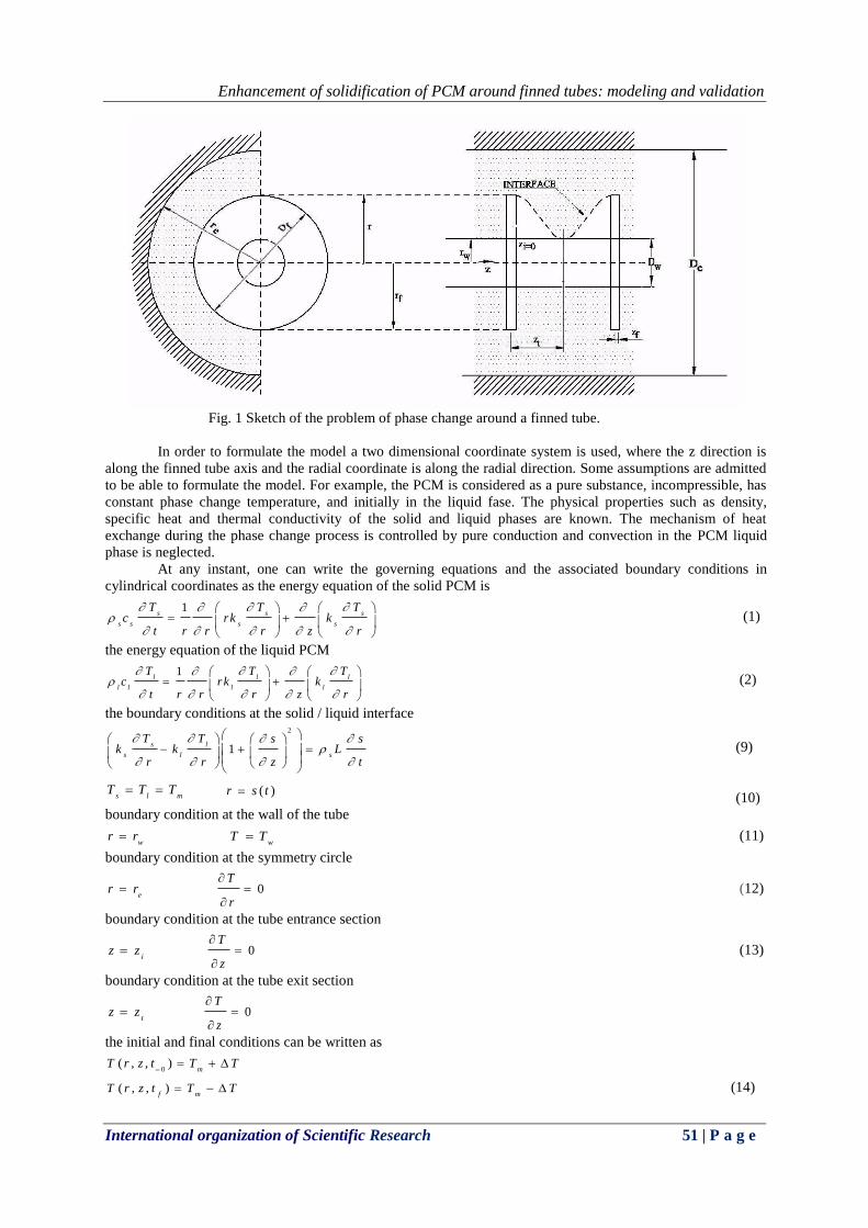
Fig. 1 Sketch of the problem of phase change around a finned tube.
In order to formulate the model a two dimensional coordinate system is used, where the z direction is
along the finned tube axis and the radial coordinate is along the radial direction. Some assumptions are admitted
to be able to formulate the model. For example, the PCM is considered as a pure substance, incompressible, has
constant phase change temperature, and initially in the liquid fase. The physical properties such as density,
specific heat and thermal conductivity of the solid and liquid phases are known. The mechanism of heat
exchange during the phase change process is controlled by pure conduction and convection in the PCM liquid
phase is neglected.
At any instant, one can write the governing equations and the associated boundary conditions in
cylindrical coordinates as the energy equation of the solid PCM is
1s s s
s s s s
T T Tc rk k
t r r r z r
(1)
the energy equation of the liquid PCM
1l l l
l l l l
T T Tc rk k
t r r r z r
(2)
the boundary conditions at the solid / liquid interface 2
1s l
s l s
T T s sk k L
r r z t
(9)
s l mT T T
( )r s t
(10)
boundary condition at the wall of the tube
wr r
wT T (11)
boundary condition at the symmetry circle
er r 0
T
r
(12)
boundary condition at the tube entrance section
iz z 0
T
z
(13)
boundary condition at the tube exit section
tz z 0
T
z
the initial and final conditions can be written as
0( , , )
mT r z t T T
( , , )f m
T r z t T T (14)
Enhancement of solidification of PCM around finned tubes: modeling and validation
International organization of Scientific Research 52 | P a g e
where is half of the phase change temperature range.
The enthalpy of the PCM per unit volume, Bonacina et al. [14], can be written as:
m
T
H T C T d T T T (15)
where
Specific heat per unit volume;
Latent heat of solidification;
: Unit step function.
the thermal capacity per unit volume can be defined as:
m
d H TC T C T T T
d T (16)
Where is the Dirac delta fuction and
( )
( )
s m
l m
C T T T TC T
C T T T T
(17)
Where sC and lC are the thermal capacities in the solid and liquid phases, respectively.
Substituting eq. 16 into eq. 15 one can obtain the equivalent thermal capacity per unit volume
integrated over the phase change range as
m m m
m m m
T T T T T
s l
T T T T T
H T C T d T C T d T C T d T
(18)
the thermal conductivity can be written in a similar manner as
( ) T ( )
( ) T
s m
l m
k T T Tk T
k T T T
(19)
Considering that sC and lC do not depend on the phase change temperature range and that sk and
lk change linearly in the phase change temperature range one can write:
( );
( ) ( );
( ) ( ); - < T
2 2
s m
l m
s l
m m
C T T T T
C T C T T T T
C T C TT T T T
T
(20)
( ) ; T
( ) ( ); T
( ) ( )( ) ;
2
s m
l m
l s
l m m
k T T T
k T k T T T
k T k Tk T T T T T T T
T
m
T T
(21)
where
L
cC
cC
s
lll
sss
(22)
Using eqs. 20-22 with eqs.1 and 2 the energy equations of the solid and liquid phases as well as the
phase interface equation can be expressed in a single form as in eq. 23.
1T T T
C T rk T k Tt r r r z z
(23)
When using eq. 24 for the fin the fin thermal properties must be used, that is
Enhancement of solidification of PCM around finned tubes: modeling and validation
International organization of Scientific Research 53 | P a g e
f f f
f
C T c C
k T k
(24)
To facilitate the numerical calculations eq. 23 and the associated boundary, initial and final conditions
are expressed in dimensionless form by using the following dimensionless parameters and variables
2
; ;
; ;
; ;
; ;
; ;
;
r
m r w
s s
s l
ls
s w s
l s s
ls T
s s
f
fs
s m w
f
fs
s w
T T rR
T T T r
k Ck C
k C
k t CC
C r C
k C T C Tk S te
k L
C TC
C T T
k zk Z
k r
(25)
eq. 23 in terms of the new variables is
Zk
ZRkR
RR
1C (26)
while the boundary conditions become
tube wall:
0w
1R
symmetry circle:
0R
eR R (27)
initial interface position:
0Z
0
iZ Z
final interface position:
0Z
tZ Z
Initial and final conditions are respectively:
1
1 2 (28)
The set of equations of the model and the boundary and initial conditions were implemented in a
computational code. Experimental tests were realized to ensure that the results are independent of the choice of
the number of grid points. The grid points which make the results independent according to the numerical tests is
found to be 45 along the tube while the number of grid points along the radial fin is taken as 33 points. The time
step is taken as 10-3
s. These values are used in all the numerical simulations.
III. EXPERIMENTAL ANALYSIS In order to validate the model and the numerical predictions an experimental set up is constructed and
instrumented as shown in Fig. 2. The test set up is composed of a compression refrigerant circuit, secondary fluid
circuit, coiled tube heat exchanger submersed in the secondary fluid tank, the test section of the finned tube
which is connected to the secondary fluid circuit. The secondary fluid is Ethanol cooled by the refrigerant
flowing through the coiled tube heat exchanger and its temperature and mass flow rate are controlled as required.

Enhancement of solidification of PCM around finned tubes: modeling and validation
International organization of Scientific Research 54 | P a g e
The test section is of rectangular shape built from 15 mm thick acrylic sheet with the test tube extended across
the test section filled with PCM (water) whose initial temperature can be varied as desired. High resolution
digital camera is used to photograph the finned tube and the reference scale to be used to convert the image
dimensions to real values as will be explained later. Calibrated thermocouples type K, are fixed at entry and exit
of the finned tube, in the PCM test tank, along the finned tube and in the secondary fluid tank. The
thermocouples were calibrated to within ±0.5 oC, image conversion precision to within ±0.1mm while the mass
flow rate (measured by a calibrated orifice plate) to within ±10-4
kg/s.
Measurements were usually taken when the desired testing conditions were achieved, that is the
temperature of the working fluid in the finned tube, temperature of the Ethanol tank, temperature of the PCM,
and the mass flow rate of the secondary fluid. Under these initial conditions the chronometer is started after all
initial conditions are registered. During the first two hours each 5 minutes period all measurement points are
registered and a photograph of the finned tube is taken. During the third hour measurements are registered each
15 minutes interval. After that the time interval is increased to 30 minutes until the end of the test. The test is
considered terminated when no change in temperature or interface position is registered during three successive
time intervals.
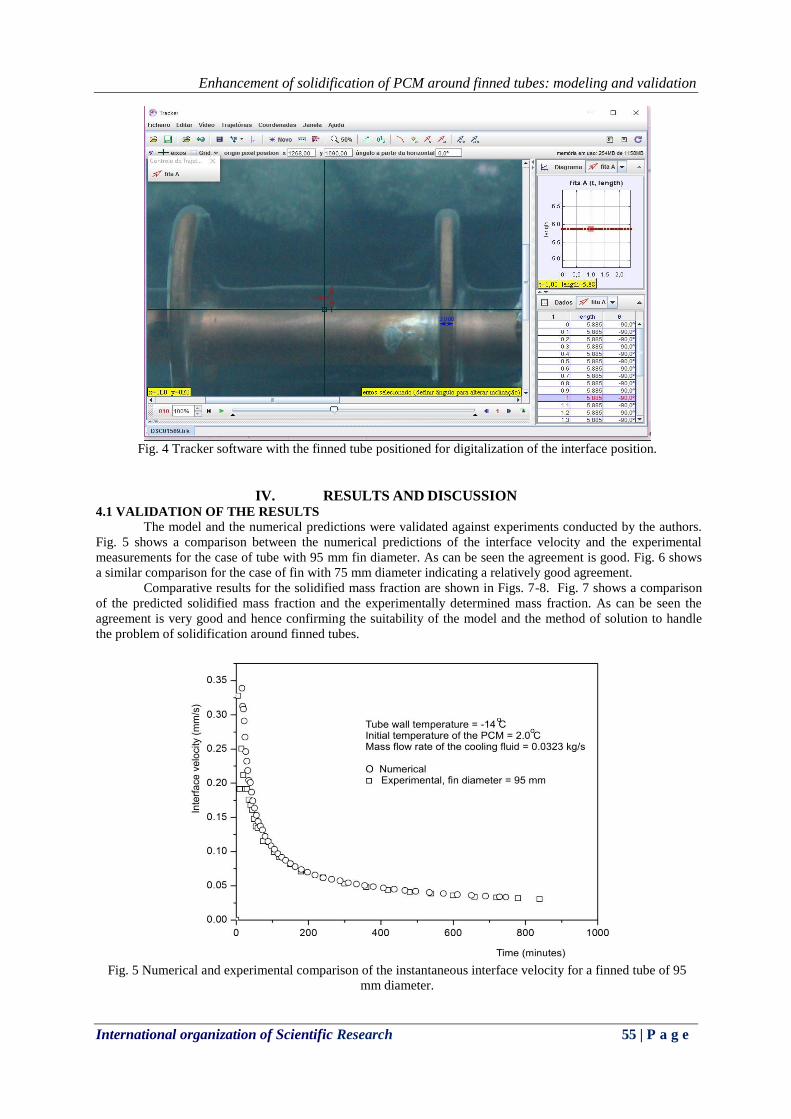
A typical photograph of the finned tube is shown in Fig. 3 where the interface position is tracked and
converted to real dimension by using the program Tracker as shown in Fig. 4.
Fig. 2 The experimental installation.
Fig. 3 The finned tube, the solidified PCM and the thermocouples for temperature measurements.
Enhancement of solidification of PCM around finned tubes: modeling and validation
International organization of Scientific Research 55 | P a g e
Fig. 4 Tracker software with the finned tube positioned for digitalization of the interface position.
IV. RESULTS AND DISCUSSION 4.1 VALIDATION OF THE RESULTS
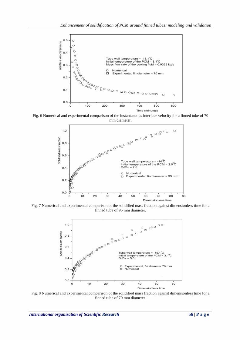
The model and the numerical predictions were validated against experiments conducted by the authors.
Fig. 5 shows a comparison between the numerical predictions of the interface velocity and the experimental
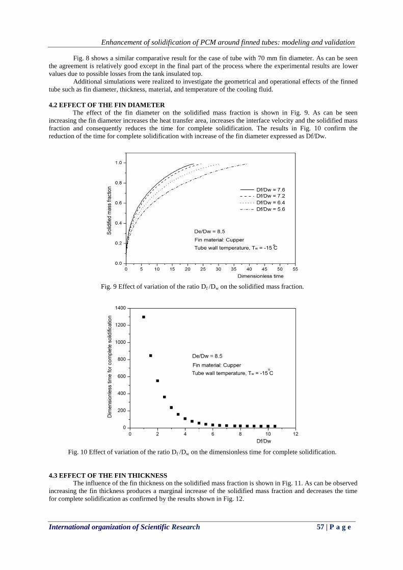
measurements for the case of tube with 95 mm fin diameter. As can be seen the agreement is good. Fig. 6 shows
a similar comparison for the case of fin with 75 mm diameter indicating a relatively good agreement.
Comparative results for the solidified mass fraction are shown in Figs. 7-8. Fig. 7 shows a comparison
of the predicted solidified mass fraction and the experimentally determined mass fraction. As can be seen the
agreement is very good and hence confirming the suitability of the model and the method of solution to handle
the problem of solidification around finned tubes.
Fig. 5 Numerical and experimental comparison of the instantaneous interface velocity for a finned tube of 95
mm diameter.
Enhancement of solidification of PCM around finned tubes: modeling and validation
International organization of Scientific Research 56 | P a g e
Fig. 6 Numerical and experimental comparison of the instantaneous interface velocity for a finned tube of 70
mm diameter.
Fig. 7 Numerical and experimental comparison of the solidified mass fraction against dimensionless time for a
finned tube of 95 mm diameter.
Fig. 8 Numerical and experimental comparison of the solidified mass fraction against dimensionless time for a
finned tube of 70 mm diameter.
Enhancement of solidification of PCM around finned tubes: modeling and validation
International organization of Scientific Research 57 | P a g e
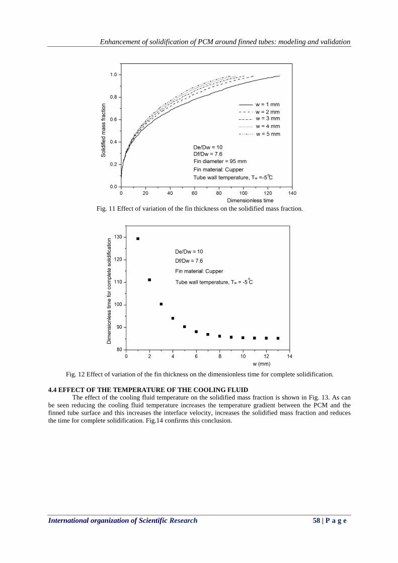
Fig. 8 shows a similar comparative result for the case of tube with 70 mm fin diameter. As can be seen
the agreement is relatively good except in the final part of the process where the experimental results are lower
values due to possible losses from the tank insulated top.
Additional simulations were realized to investigate the geometrical and operational effects of the finned
tube such as fin diameter, thickness, material, and temperature of the cooling fluid.
4.2 EFFECT OF THE FIN DIAMETER
The effect of the fin diameter on the solidified mass fraction is shown in Fig. 9. As can be seen
increasing the fin diameter increases the heat transfer area, increases the interface velocity and the solidified mass
fraction and consequently reduces the time for complete solidification. The results in Fig. 10 confirm the
reduction of the time for complete solidification with increase of the fin diameter expressed as Df/Dw.
Fig. 9 Effect of variation of the ratio Df /Dw on the solidified mass fraction.
Fig. 10 Effect of variation of the ratio Df /Dw on the dimensionless time for complete solidification.
4.3 EFFECT OF THE FIN THICKNESS
The influence of the fin thickness on the solidified mass fraction is shown in Fig. 11. As can be observed
increasing the fin thickness produces a marginal increase of the solidified mass fraction and decreases the time
for complete solidification as confirmed by the results shown in Fig. 12.
Enhancement of solidification of PCM around finned tubes: modeling and validation
International organization of Scientific Research 58 | P a g e
Fig. 11 Effect of variation of the fin thickness on the solidified mass fraction.
Fig. 12 Effect of variation of the fin thickness on the dimensionless time for complete solidification.
4.4 EFFECT OF THE TEMPERATURE OF THE COOLING FLUID
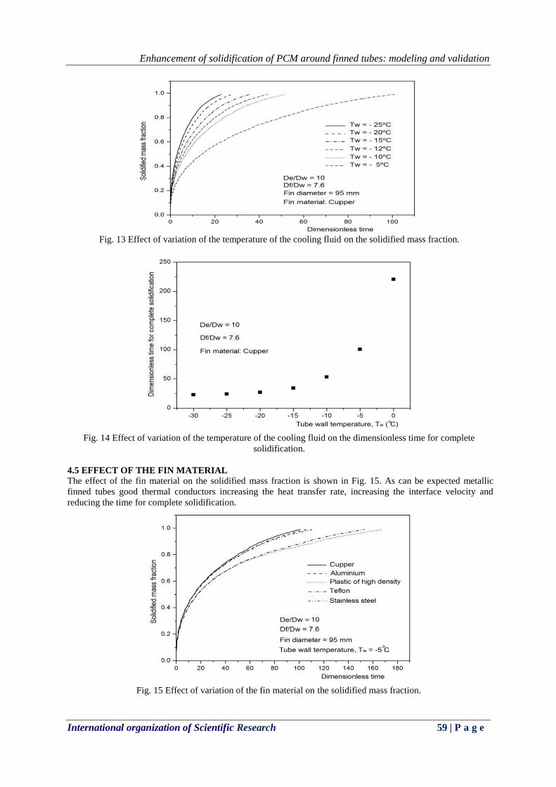
The effect of the cooling fluid temperature on the solidified mass fraction is shown in Fig. 13. As can
be seen reducing the cooling fluid temperature increases the temperature gradient between the PCM and the
finned tube surface and this increases the interface velocity, increases the solidified mass fraction and reduces
the time for complete solidification. Fig.14 confirms this conclusion.
Enhancement of solidification of PCM around finned tubes: modeling and validation
International organization of Scientific Research 59 | P a g e
Fig. 13 Effect of variation of the temperature of the cooling fluid on the solidified mass fraction.
Fig. 14 Effect of variation of the temperature of the cooling fluid on the dimensionless time for complete
solidification.
4.5 EFFECT OF THE FIN MATERIAL
The effect of the fin material on the solidified mass fraction is shown in Fig. 15. As can be expected metallic
finned tubes good thermal conductors increasing the heat transfer rate, increasing the interface velocity and
reducing the time for complete solidification.
Fig. 15 Effect of variation of the fin material on the solidified mass fraction.
Enhancement of solidification of PCM around finned tubes: modeling and validation
International organization of Scientific Research 60 | P a g e
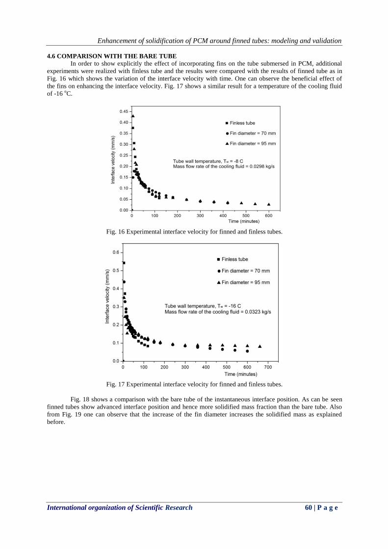
4.6 COMPARISON WITH THE BARE TUBE
In order to show explicitly the effect of incorporating fins on the tube submersed in PCM, additional
experiments were realized with finless tube and the results were compared with the results of finned tube as in
Fig. 16 which shows the variation of the interface velocity with time. One can observe the beneficial effect of
the fins on enhancing the interface velocity. Fig. 17 shows a similar result for a temperature of the cooling fluid
of -16 oC.
Fig. 16 Experimental interface velocity for finned and finless tubes.
Fig. 17 Experimental interface velocity for finned and finless tubes.
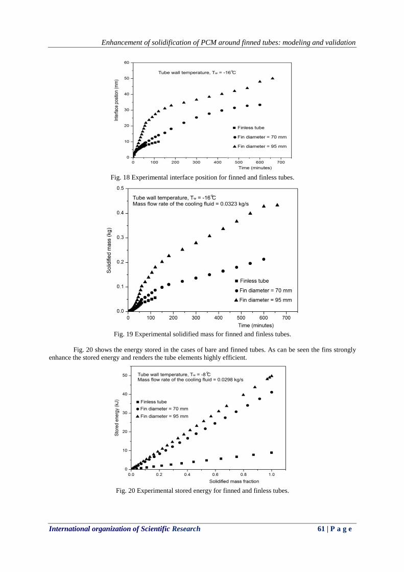
Fig. 18 shows a comparison with the bare tube of the instantaneous interface position. As can be seen
finned tubes show advanced interface position and hence more solidified mass fraction than the bare tube. Also
from Fig. 19 one can observe that the increase of the fin diameter increases the solidified mass as explained
before.
Enhancement of solidification of PCM around finned tubes: modeling and validation
International organization of Scientific Research 61 | P a g e
Fig. 18 Experimental interface position for finned and finless tubes.
Fig. 19 Experimental solidified mass for finned and finless tubes.
Fig. 20 shows the energy stored in the cases of bare and finned tubes. As can be seen the fins strongly
enhance the stored energy and renders the tube elements highly efficient.
Fig. 20 Experimental stored energy for finned and finless tubes.
Enhancement of solidification of PCM around finned tubes: modeling and validation
International organization of Scientific Research 62 | P a g e
V. CONCLUSIONS
In the present study a model is developed for the solidification of PCM around a tube with radial fin
and was validated against experimental measurements. The numerical predictions and the experimental
measurements revealed that increasing the fin diameter increases the interface velocity and reduces the time for
complete solidification. Reducing the temperature of the cooling fluid enhances the interface velocity and
reduces the time for complete solidification. The fin thickness appears to have little influence on the interface
velocity or the time for complete solidification. Metallic fins seem to enhance the solidification process
increasing the interface velocity and reducing the solidification time.
Few remarks are important to avoid misusing the present results. First of all the symmetry radius should
be larger than the fin radius to avoid inefficiency of the process. The cooling fluid temperature should not be too
low to avoid inefficiency of the refrigeration machine, a compromise between the low temperature and the
solidification time should be established. Finally it is attractive to have finned tubes due to their good thermal
performance. The cost of fabricating these tubes is relatively high due to the soldering process. An alternative
solution is to use plastic tubes with impregnated metallic powder to improve their effective thermal conductivity.
This at the moment is under development in our laboratory.
VI. ACKNOWLEDGEMENTS The authors wish to thank the CNPQ for the PQ research grant to the first author and FAPEAM for the
master scholarship to the second author.
VII. NOMENCLATURE c Specific heat [J kg
-1K
-1]
C Heat capacity per unit volume = c [J m-3
K]
TC Heat capacity per unit volume including the phase change [J m-3
K]
H Enthalpy per unit volume [J m-3
]
k Thermal conductivity [W m-1
K-1
]
Tk Thermal conductivity including the phase change [W m-1
K-1
]
L Latent heat [J kg-1
]
r Radial coordinate [m]
R Dimensionless radial coordinate = wr/r
rw External radius of the tube [m]
ri Internal radius of the tube [m]
re Radius of external cylinder or radius of the symmetry circle [m]
rs Radial position of the solid / liquid interface [m]
s(t) Interface position [m]
T Temperature [K]
Tm Phase change temperature [K]
Tw Tube wall temperature [K]
z Axial coordinate [m]
Z Dimensionless axial coordinate= wr/z
Greek letters
Dirac delta function
T Half the phase change temperature range [K]
Dimensionless temperature
Unit function
Latent heat per unit volume [J m-3]
Density [kg m-3]
Dimensionless time = sws crtk
Dimensionless phase change temperature range = wm TTT
Subscripts
f fin
liquid
Enhancement of solidification of PCM around finned tubes: modeling and validation
International organization of Scientific Research 63 | P a g e
s solid
w wall
Abbreviations
PCM Phase Change Material
ADI Alternating Direction Implicit
REFERENCES [1] R. H. Henze and J. A. C. Humphrey, Enhanced heat conduction in phase-change thermal energy storage
devices, Int. Journal Heat Mass Transfer, 24, 1981, 459-474.
[2] P. V. Padmanabhan and M. V. K. Murthy, Outward phase change in a cylindrical annulus with axial fins
on the inner tube, In. J. Heat Mass Transfer, 29 (12), 1986, 1855-1868.
[3] K. A. R. Ismail, C. L. F. Alves, and M. S. Modesto, Numerical and experimental study on the
solidification of PCM around a vertical axially finned isothermal cylinder, Applied Thermal Engineering,
21 (1), 2001, 53–77.
[4] K. A. R. Ismail and M. G. E. Silva, Numerical solution of the Phase change problem around a horizontal
cylinder with convection in the melt region, Int. Journal of Heat and Mass Transfer, 46 (10), 2003, 1791-
1799.
[5] Z. Liu, X. Sun, C. Ma, Experimental investigations on the characteristics of melting processes of stearic
acid in an annulus and its thermal conductivity enhancement by fins, Energy Conversion and
Management, 46, 2005, 959–969.
[6] N. Kayansayan, M. A. Acar, Ice formation around a finned-tube heat exchanger for cold thermal energy
storage, Int. Journal of Thermal Sciences, 45, 2006, 405–418.
[7] N. Yuksel, A. Avci and M. Kilicn, A model for latent heat energy storage systems, Int. J. Energy
Research, 30, 2006, 1146–1157.
[8] S. Jegadheeswaran, S. D. Pohekar, Energy and exergy analysis of particle dispersed latent heat storage
system, Int. Journal of Energy and Environment, 1 (3), 2010, 445-458.
[9] K. Chintakrinda, R. D. Weinstein and A. S. Fleischer, A direct comparison of three different material
enhancement methods on the transient thermal response of paraffin phase change material exposed to
high heat fluxes, Int. Journal of Thermal Sciences, 50, 2011, 1639-1647.
[10] M. R. Anisur, M. H. Mahfuz, M. A. Kibria, R. Saidur, I. H. S. C. Metselaar, T. M. I. Mahlia, Curbing
global warming with phase change materials for energy storage, Renewable and Sustainable Energy
Reviews, 18, 2013, 23–30.
[11] M. Rahimi, A. A. Ranjbar, D. D. Ganji, K. Sedighi, and M. J. Hosseini, Experimental investigation of
phase change inside a finned-tube heat exchanger, Hindawi Publishing Corporation Journal of
Engineering, 2014, Article ID 641954, 11 pages, http://dx.doi.org/10.1155/2014/641954.
[12] K. A. R. Ismail, M. M. Gonçalves and F. A. M. Lino, A parametric study of solidification of PCM in an
annulus with alternating fins, Int. Journal of Research in Engineering and Advanced Technology, 3 (4),
2015, 188-202, August-September.
[13] K. A. R. Ismail, M. M. Gonçalves and F. A. M. Lino, Solidification of PCM around a finned tube:
modeling and experimental validation, Journal of Basic and Applied Research International, 12 (2), 2016,
115-128.
[14] C. .Bonacina, G. Comini, A. Fasano, M. Primiceiro, Numerical solutions of phase change problems, Int.
Journal Heat and Mass Transfer, 16 (15), 1973, 1825-1832.