ieee internet of things journal, vol. 14, no. …weisong/papers/zhang18-aaa.pdf · this is too...
TRANSCRIPT

IEEE INTERNET OF THINGS JOURNAL, VOL. 14, NO. 8, AUGUST 2018 1
Distributed Collaborative Execution on the Edgesand Its Application to AMBER Alerts
Qingyang Zhang, Student member, IEEE, Quan Zhang, Weisong Shi, Fellow, IEEE and Hong Zhong
Abstract—In the Internet of Everything (IoE) era, billions ofgeographically distributed things will connect to the Internet andgenerate hundreds of zettabytes of data per year. Pushing thatdata to the cloud requires tremendous network bandwidth costand latency. This is too onerous for some latency-sensitive appli-cations, such as vehicle tracking using city-wide cameras. Oneapplication currently limited by such obstacles is the AMBERAlert system–but edge computing could transform this system’scapabilities. Edge computing is a new computing paradigm thatgreatly diminishes data transmission and response latency byprocessing data at the proximity of data sources. However, mostvision-based analytics are compute-intensive, and an edge devicemight be overwhelmed given tens of frames each second for real-time analysis. Also, the system needs a customized and flexibleinterface to implement efficient tracking strategies. To meetthese needs, here we extend a big data processing framework,called Firework, to support collaboration between multiple edgedevices and customizable task-scheduling strategies. Based onthis extended version of Firework, we implement the AMBERAlert Assistant (A3), which efficiently tracks and locates a vehicleby analyzing city cameras’ data in real time. We also proposetwo kinds of customized task-scheduling algorithms for vehicletracking in A3. Comprehensive evaluation results show thatA3 achieves real-time video analytics by collaborating amongmultiple edge devices; and the proposed location-direction-relateddiffusion strategy effectively controls the searching area forvehicle tracking by smartly selecting candidate cameras.
Index Terms—edge computing; AMBER alert; public safety;video analytics.
I. INTRODUCTION
IN the last decade, researchers and practitioners have treatedcloud computing [1] as the de facto large-scale data
processing platform. Numerous cloud-centric data processingplatforms [2]–[7] that leverage the MapReduce [8] program-ming framework, have been proposed for both batched andstreaming data. In recent years, we have witnessed the onsetof the Internet of Everything (IoE) era [9], where billions ofgeographically distributed sensors and actuators are connectedand immersed in our daily life. As one of the most sophis-ticated IoE application, real-time video analytics promises tosignificantly improve public safety. Video Analytics leverageinformation and knowledge from video data content to addressa particular applied information processing need; and as thepublic safety community massively adopts this technology,
Qingyang Zhang and Hong Zhong are with the School of Computer Scienceand Technology, Anhui University, Hefei, China, 230601.E-mail: [email protected], [email protected]
Quan Zhang and Weisong Shi are with the Department of ComputerScience, Wayne State University, Detroit, MI, U.S.A., 48202. Qingyang Zhangwas a visitng student at Wayne State University while working on this project.E-mail: quan.zhang, [email protected]
Manuscript received December 1, 2017; revised March 1, 2018.
it provides near real-time situational awareness of citizens’safety and urban environments, including automating the la-borious tasks of monitoring live video streams, streamliningvideo communications and storage, providing timely alerts,and making the task of searching enormous video archivestractable [10]. However, the conventional cloud-centric dataprocessing model is inefficient to process all IoE data in datacenters especially for the response latency, network bandwidthcost, and possible privacy concerns, given the zettabytes ofdata generated by edge devices [11], [12]. On the other hand,rarely are data shared among multiple stakeholders–a varietyof concerns restrict video analytics’ practical deployment, eventhough video data analytics could take advantage of manydata sources to make a smart decision. Moreover, there isno efficient data processing framework for the community toprogram and deploy easily for public safety applications acrossgeographically distributed data sources.
Edge computing could serve as a major boon to trans-form this technology, however. The emerging field of edgecomputing (also known as fog computing [13], mobile edgecomputing [14] or Cloudlet [15]–[20]) refers to “the enablingtechnologies allowing computation to be performed at theedge of the network, on downstream data on behalf of cloudservices and upstream data on behalf of IoE services” [21].It complements the existing cloud computing model andenables data processing at the proximity of data sources, whichis promising for latency-sensitive applications that leveragecomputing resources at the close edge instead of in the remotecloud.
Edge
Video
Valuable
dataObject detection
Object tracking
Smart blurring
Video clipping
Fig. 1. Edge video analytics for public safety.

IEEE INTERNET OF THINGS JOURNAL, VOL. 14, NO. 8, AUGUST 2018 2
As Figure 1 shows, given the edge nodes deployed alongthe data propagation path between cameras and the cloud, wecan process the partial (for example, license plate extraction,feature extraction, smart blurring, and video clipping) or entireworkload as the video stream arrives, which significantlyreduces the video data transmission’s size, and consequentlythe network bandwidth cost. Then we send the semi- or fully-processed data to the cloud for aggregation-based analytics.Moreover, we can share the services deployed at the edgenodes and intermediate data generated by the edge nodeswith other stakeholders, and then compose a customized videoanalytics application by leveraging these existing intermediatedata/services.
Beyond processing data in real time, this distributed andcollaborative application in an edge-cloud environment alsooffers increased reliability, leading to a quicker response. Take,for example, the America’s Missing Broadcast EmergencyResponse (AMBER) alert system. Right now, tracking a sus-pect’s vehicle heavily relies on the reports of witnesses. Butwhat if we leveraged edge computing instead, so a licenseplate-recognition (LPR) application running city-wide securitycameras could significantly improve the efficiency of suspectvehicle tracking? Then, the local license plate-recognition pro-cess for an image could respond in milliseconds without datatransmission, instead of waiting for seconds to communicatewith a remote data center, which is far quicker than the timerequired to send the image to the data center, process the data,and retrieve the results. The potential consequence is stark;this could mean the difference between identifying the missingchild immediately versus losing the child in sight. Moreover,the network traffic caused by sending a deluge of data to adata center significantly impacts network performance, whichfurther intensifies the response latency and data transmissioncost.
To realize the vision of edge computing and real-timevideo analytics for public safety, we must tackle severalbarriers systematically: First, there is no existing programmingtool and framework that allows programmers to build cost-effective real-time applications among various geographicallydistributed data sources. Second, most video analytics algo-rithms undoubtedly are computationally intensive, of whichhundreds of milliseconds might be taken to process onevideo frame on edge nodes [22] , so that the edge deviceis overwhelmed given the tens of frames in a second. Thus,the collaboration among multiple edge nodes would ensurehigh resource usage and provide opportunities to balance theworkload. However, realizing efficient resource managementand task scheduling are difficult in an edge computing envi-ronment, where the edge nodes primarily are heterogeneous,with various types of network connectivity. Third, efficienttask scheduling might require user intervention, in whichdomain knowledge could be applied to boost the performance.However, rarely is user intervention considered in task alloca-tion, especially when the application-defined network topologydiffers from the physical network topology.
To tackle the aforementioned issues, we extend our previ-ous work on Firework [23], [24].Specifically, we implementa collaborative mechanism among multiple edge nodes for
real-time data processing and a programming interface toconstruct a customized task-scheduling strategy, depending onthe application-defined network topology. Based on Firework’sextensions, we implement the AMBER Alert Assistant (A3)system, which aims to improve target tracking efficiency (thatis, tracking suspect’s vehicles) using the AMBER Alert system.By implementing multiple customized task-scheduling strate-gies, we evaluate various target-tracking strategies relying onthe status of real-time video analysis results.
The rest of the paper is organized as follows. We describeour motivation in Section II and present the Firework’s ex-tensions in Section III. We discuss the proposed A3 systemin Section IV. Section V focuses on experiments and results.We review related work in Section VI. Finally, we concludein Section VII.
II. MOTIVATION
A. AMBER Alert
The AMBER Alert is a system that alters the public tochild abductions that is implemented with different namesin different countries [25]. In the United States, when akidnapping occurs, an alert is sent to citizens’ smart phoneimmediately if they are near the event location. The alertusually includes descriptive information about this event, suchas time, location, the kidnapper’s vehicle license plate number,and a description of the child or kidnapper. Then, witnessescan provide pertinent information to the police department ifthey spot the kidnapper’s vehicle on the road. But, trackinga suspect’s vehicle heavily relies on the reports of witnesses,which is inefficient, because many people miss the alert ormight not recognize the suspect’s vehicle.
Nowadays, video surveillance is common in cities, includingsecurity cameras, traffic cameras, and even smartphone/on-dash cameras. For example, participants in Project GreenLight [26] provide their video data for public safety, whichincludes more than a hundred cameras in Detroit, Michigan.Using an automatic license plate-recognition (ALPR) tech-nique, video surveillance greatly improves the tracking ofkidnappers’ vehicles. Coped with the privacy issues, othercameras (i.e., the cameras in the Project Green Light, on-dashcar cameras, smart phone cameras) might provide video databy the owners.
Usually, the network bandwidth requirements of a 720P,1080P, and 4K live video are 3.8 Mbps, 5.8 Mbps, and19 Mbps, respectively. Thus, pushing all video data to thecloud leads to huge data transmission costs and high latency.Considering the amount of data generated by many camerassimultaneously, cloud-based solutions are no longer suitablefor real-time video analytics, due to high data transmissioncosts, bandwidth requirements, and onerous latency. Edgecomputing processes data locally, which significantly reducesthe data transmission cost and lowers network bandwidthrequirements. But it still has two barriers that prevent real-time vehicle tracking in the AMBER Alert system:
1) limitations of edge devices: Most computer vision algo-rithms are compute-intensive, such as object detection, facerecognition, and optical character recognition (OCR). Thus,

IEEE INTERNET OF THINGS JOURNAL, VOL. 14, NO. 8, AUGUST 2018 3
TABLE IPROCESSING TIME FOR PLATE RECOGNITION IN THE VIDEO.
Edge Device Video Decoding (ms) Motion Detection (ms) Plate Detection (ms) Plate Recognition (ms)
Amazon EC2 t2 node 4.83 53.35 136.31 16.92Dell Inspiron 5559 3.76 42.07 121.40 13.92Dell Wyse 14.35 158.75 601.32 53.80Dell OptiPlex 3.51 38.75 95.67 12.47
the edge node might lack the computation resources needed toprocess video in real time. For vehicle tracking, an open sourceALPR system is built, called OpenALPR [27], which usuallyhas two stages: license plate detection and license recognition.The latter usually employs the OCR technique. Because of itsvideo streaming features, it is worthwhile to consider video de-coding; we also implemented motion detection using OpenCV[28], which detects the different areas between two framesand avoids needless license plate detection and recognition.Here, we measure OpenALPR’s [27] performance on differentdevices, including the Amazon Elastic Compute Cloud t2 node(Amazon EC2 t2: an Amazon virtual machine with Intel XeonCPU at 2.4 GHz), Dell Inspiron 5559 (a laptop with Intel i7-6500U at 2.5 GHz, going up to 3.1 GHz), Dell Wyse (a homegateway with Intel N2807 at 1.58 GHz) and Dell OptiPlex (anIntel i5-4590 at 3.3 GHz, going up to 3.7 GHz).
Figure 2 shows that an ALPR system without motiondetection will cost much more than the one with motiondetection executing on an Amazon EC2 t2 node. This isbecause motion detection marks the moving area between twoframes, which significantly reduces the workload of the lattersteps by reducing the recognition area. Table I shows the timecosts on different steps of video analytics, in which the licenseplate detection contributes to the majority of processing time,and none of these devices can analyze video in real timeif only one thread is used. Note that the average LPR timewithout motion detection is 191.05 ms, and the time withmotion detection is 131.18 ms on an Amazon EC2 t2 node.The average ALPR’s complete processing times for two casesare 195.69 ms and 187.59 ms. The difference between twocases is small, which is why we use video from a peak period.We also use another set, where the time is less than 100 ms foran instance with motion detection. In this paper, we always usepeak-period video data, because it is important to consider theworst case to avoid overload. Thus, video analytics must bemultithreaded and have motion detection; both are included inour system design. Also, because LPR takes much less timeto process than license plate detection, here we simply useLPR rather than the full steps of license plate detection andrecognition.
2) Control of the vehicle tracking area: As the suspect’svehicle moves, the vehicle tracking area should enlarged; andit also should shrink (or close in on) the area once the vehicleis found. A simple method to track a vehicle is to enlargethe radius of the area as time goes by. However, the speed ofdifferent routes varies. For example, the highway allows twicethe speed of city streets. Thus, it is unreasonable to set thesame rate for different types of cameras. Furthermore, mobilecameras deployed on taxis and/or garnered by crowdsourcing
0
0.2
0.4
0.6
0.8
1
0 50 100 150 200
CD
F
Time (ms)
With motion detection
Without motion detection
Fig. 2. The time cumulative distributive function (CDF) of license platedetection and recognition on an Amazon EC2 t2 node.
private vehicles could be integrated into the system to providemore video sources. It is exceedingly difficult, though, toprovide a customized and dynamic control strategy for trackingthe suspect’s vehicle using both static and dynamic dataprovided by moving cameras.
B. Firework
To contend with these issues, we extend the Firework frame-work. Firework helps build an enhanced AMBER Alert systemon edge nodes and the cloud. However, previous versions ofFirework did not work well in the instances noted (see [24]for an overview of the previous version). Thus, we extend theframework in section III, and introduce the previous version’sarchitecture while also detailing what we extend.
Firework is a framework for big data processing and sharingamong multiple stakeholders in a collaborative edge-cloudenvironment. Firework provides an easy-to-use programminginterface to develop and deploy applications to edge nodes. Italso allows splitting the whole service into several subservices.For example, an ALPR service includes a video decodingsubservice, motion detection subservice, and license platenumber recognition subservice.
We first introduce the terminologies that describe abstractconcepts in Firework. Based on existing definitions fromprior work [24], we extend and enrich their meanings andsummarize as follows:
• Firework. This is an operational instance of the Fire-work paradigm. A Firework instance might include mul-tiple Firework.Nodes and Firework.Managers, dependingon the topology. Figure 3 shows an example of Firework

IEEE INTERNET OF THINGS JOURNAL, VOL. 14, NO. 8, AUGUST 2018 4
instance consisting of five Firework.Nodes and one Fire-work.Manager employing heterogeneous computing plat-forms. We do not distinguish the host of Firework.Nodesand Firework.Manager. If all firework nodes host on edgedevices, it will be a complete edge computing platform,and if they host on cloud virtual machines, it will be acomplete cloud platform. Also, some firework nodes areable to host on edge devices and some on cloud virtualmachines, thereby forming an edge-cloud collaborativeplatform.
• Firework.View. The Firework.View is defined as a com-bination of a dataset and functions, which is inspired byobject-oriented programming. The dataset describes thedata generated by edge devices and historical data storedin the edge or cloud. The functions define applicableoperations upon the dataset. A Firework.View could beadopted by multiple data owners who implement the samefunctions on the same type of dataset.
• Firework.Node. A Firework.Node is a device that im-plements Firework.Views, and it allocates computationresources including the CPU, memory, and network torun (sub)services. Note that the (sub)service is the workerrunning on a Firework.Node. A Firework.Node mighthave only data producers, such as sensors and mobiledevices, which publish sensed data without analyzing.While it inherits Firework.Views, it is a data consumer. Inthis case, it uses others’ functions as data sources. Here,a Firework.Node is a data producer and a data consumersimultaneously–so it senses the data and provides theprocessed data.
• Firework.Manager. This first provides centralized servicemanagement to oversee registered Firework.Views. AllFirework.Views implemented by Firework.Nodes shouldregister to the Firework.Manager. It also manages thedeployed services built on top of these views. Second,it serves as the job tracker that dispatches tasks toFirework.Nodes.1 It will monitor Firework.Nodes’ com-putation resources and optimize the running (sub)servicesvia dynamic workload balancing among multiple Fire-work.Nodes, depending on resource usage and user inter-vention. Third, it exposes available services to users sothat they can leverage existing services to compose theirown applications.
C. Distributed Collaborative Execution on the Edge
As mentioned previously, there are two barriers to com-bining edge computing with the AMBER Alert system: thelimitations of edge devices, and control of the vehicle trackingarea. These can be abstracted to two types of collaborations–the collaboration of data processing, and the collaborationof task diffusion. This leads to the requirements for a dis-tributed collaborative execution. Similar requirements existin other edge computing applications. For example, consider
1A service is from the users’ view, and one service can be split intoseveral subservices. The job and task are from the view of scheduling. A jobimplements a specific function of Firework.View, and provides that service forusers. A job might consist of several tasks that only implement a subservice.
Firework.
ManagerDatasets
Apache Spark
Functions
Firework.Node
Datasets
Databases
Functions
Firework.Node
Datasets
Apache Kafka
Functions
Firework.Node
Datasets
IoT Gateway
Functions
Firework.Node
Datasets
Smartphones
Functions
Firework.Node
Fig. 3. A high-level overview of Firework.
activity detection in a jail. By analyzing captured videos,the threatening event can be detected using several features–such as the same people crowding in several different videos.This scenario involves synthetically analyzing multiple videodata with different times to find a suspected event, whichalso needs to combine multiple edge nodes and the taskcontrol on multiple edge nodes. However, no platform orframework currently exists that can cope with both barriers.The Firework framework might be approximated for this case,and it provides a uniform programming interface to developapplications in the collaborative edge-cloud environment.
III. EXTENDED Firework SYSTEM DESIGN
Now that we have explored the motivations for this work,we present our design. We primarily focus on introducingFirework’s novel extensions. Then, we overview the prototypeimplementation and introduce several important features.
A. System Architecture
To support the aforementioned features, the previous Fire-work version is extended. As with the previous version ofFirework, a three-layer architecture is designed (see Fig. 4),which consists of Service Management, Job Management,and Executor Management. The Service Management layerperforms service discovery and deployment, and a new modulecalled Access Control is added for providing a uniform accesspoint to other nodes in Firework. The Job Management layermanages services running on a computing node. The functionsof the three original modules are merged into a new TaskDispatch, and two new modules called Task Monitor and JobSchedule are added. The Executor Management layer managescomputing resources.
Because the steps deploying services have been introducedin previous work, we only discuss them briefly here. Then weintroduce each layer in this new, extended version of Firework.
To deploy a service on Firework, a user must implementat least one Firework.View, which defines the shared dataand functions, and a deployment plan, which describes howcomputing nodes are connected and how services are assignedto the computing nodes. Upon registering a service (i.e.,Firework.View), Firework.Manager creates a service stub for
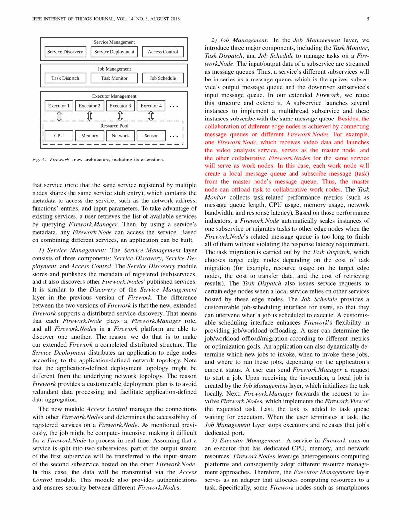
IEEE INTERNET OF THINGS JOURNAL, VOL. 14, NO. 8, AUGUST 2018 5
Service Discovery Service Deployment
Service Management
Job Management
Access Control
Executor 1
Executor Management
Executor 2 Executor 3
CPU
Resource Pool
Memory Network Sensor
Executor 4
Task Dispatch Task Monitor Job Schedule
Fig. 4. Firework’s new architecture, including its extensions.
that service (note that the same service registered by multiplenodes shares the same service stub entry), which contains themetadata to access the service, such as the network address,functions’ entries, and input parameters. To take advantage ofexisting services, a user retrieves the list of available servicesby querying Firework.Manager. Then, by using a service’smetadata, any Firework.Node can access the service. Basedon combining different services, an application can be built.
1) Service Management: The Service Management layerconsists of three components: Service Discovery, Service De-ployment, and Access Control. The Service Discovery modulestores and publishes the metadata of registered (sub)services,and it also discovers other Firework.Nodes’ published services.It is similar to the Discovery of the Service Managementlayer in the previous version of Firework. The differencebetween the two versions of Firework is that the new, extendedFirework supports a distributed service discovery. That meansthat each Firework.Node plays a Firework.Manager role,and all Firework.Nodes in a Firework platform are able todiscover one another. The reason we do that is to makeour extended Firework a completed distributed structure. TheService Deployment distributes an application to edge nodesaccording to the application-defined network topology. Notethat the application-defined deployment topology might bedifferent from the underlying network topology. The reasonFirework provides a customizable deployment plan is to avoidredundant data processing and facilitate application-defineddata aggregation.
The new module Access Control manages the connectionswith other Firework.Nodes and determines the accessibility ofregistered services on a Firework.Node. As mentioned previ-ously, the job might be compute- intensive, making it difficultfor a Firework.Node to process in real time. Assuming that aservice is split into two subservices, part of the output streamof the first subservice will be transferred to the input streamof the second subservice hosted on the other Firework.Node.In this case, the data will be transmitted via the AccessControl module. This module also provides authenticationsand ensures security between different Firework.Nodes.
2) Job Management: In the Job Management layer, weintroduce three major components, including the Task Monitor,Task Dispatch, and Job Schedule to manage tasks on a Fire-work.Node. The input/output data of a subservice are streamedas message queues. Thus, a service’s different subservices willbe in series as a message queue, which is the upriver subser-vice’s output message queue and the downriver subservice’sinput message queue. In our extended Firework, we reusethis structure and extend it. A subservice launches severalinstances to implement a multithread subservice and theseinstances subscribe with the same message queue. Besides, thecollaboration of different edge nodes is achieved by connectingmessage queues on different Firework.Nodes. For example,one Firework.Node, which receives video data and launchesthe video analysis service, serves as the master node, andthe other collaborative Firework.Nodes for the same servicewill serve as work nodes. In this case, each work node willcreate a local message queue and subscribe message (task)from the master node’s message queue. Thus, the masternode can offload task to collaborative work nodes. The TaskMonitor collects task-related performance metrics (such asmessage queue length, CPU usage, memory usage, networkbandwidth, and response latency). Based on those performanceindicators, a Firework.Node automatically scales instances ofone subservice or migrates tasks to other edge nodes when theFirework.Node’s related message queue is too long to finishall of them without violating the response latency requirement.The task migration is carried out by the Task Dispatch, whichchooses target edge nodes depending on the cost of taskmigration (for example, resource usage on the target edgenodes, the cost to transfer data, and the cost of retrievingresults). The Task Dispatch also issues service requests tocertain edge nodes when a local service relies on other serviceshosted by these edge nodes. The Job Schedule provides acustomizable job-scheduling interface for users, so that theycan intervene when a job is scheduled to execute. A customiz-able scheduling interface enhances Firework’s flexibility inproviding job/workload offloading. A user can determine thejob/workload offload/migration according to different metricsor optimization goals. An application can also dynamically de-termine which new jobs to invoke, when to invoke these jobs,and where to run these jobs, depending on the application’scurrent status. A user can send Firework.Manager a requestto start a job. Upon receiving the invocation, a local job iscreated by the Job Management layer, which initializes the tasklocally. Next, Firework.Manager forwards the request to in-volve Firework.Nodes, which implements the Firework.View ofthe requested task. Last, the task is added to task queuewaiting for execution. When the user terminates a task, theJob Management layer stops executors and releases that job’sdedicated port.
3) Executor Management: A service in Firework runs onan executor that has dedicated CPU, memory, and networkresources. Firework.Nodes leverage heterogeneous computingplatforms and consequently adopt different resource manage-ment approaches. Therefore, the Executor Management layerserves as an adapter that allocates computing resources to atask. Specifically, some Firework nodes such as smartphones

IEEE INTERNET OF THINGS JOURNAL, VOL. 14, NO. 8, AUGUST 2018 6
Smart AP
(id=1)
Laptop
(id=6)Camera 1
(id=2)
Physical connection
Video searching
Motion detection
Tablet
(id=5)
Desktop
(id=4)
Camera 2
(id=3)
Plate recognition
Fig. 5. Two different topologies defined by an application.
or smart access points (AP) may adopt a Java virtual machine(JVM) or Docker [29], while some nodes (such as commodityservers) may employ OpenStack [30] or VMWare [31] to hostan executor.
B. Prototype Implementation
Based on the code from the previous version of Firework,we implemented a prototype of the extended Firework usingJava. In the Service Management layer, etcd [32] is usedto perform the service registration, which is a distributed,consistent key-value store for shared configuration and servicediscovery. In the future, we will aim for a more lightweightversion of this function. We use a registered service’s metadatato access the service stored in etcd, so users can access thelist of available services via etcd’s RESTful interface. Aswe mentioned, an application-defined topology is provided tocustomize the application-deployment plan. Figure 5 shows anexample where the underlying network topology differs fromthe application-defined topology. To describe an application-deployment plan, we use a JavaScript Object Notation (JSON)structure [33], which is a lightweight data-interchange formatand is completely language-independent, to represent the de-ployment plan’s features. Listing 1 shows an example of theapplication-deployment plan (including the service configura-tion and application-defined topology) for the laptop in Figure5. In the JSON structure in Listing 1, an application definesdifferent topologies with their metadata for the video searchingservice, motion detection service, and plate recognition ser-vice. According to the deployment plan, the motion detectionservice on the laptop in Figure 5 receives real-time videodata from camera 1 via real-time transport protocol (RTP) anddetect motion area. Then, the plate recognition service on thelaptop will dispatches part of tasks to the smart AP and tablet.Moreover, the laptop also migrates the video searching task tothe desktop after a time threshold thus the later can recognizeplate numbers in the video of camera 2, which are connectedby a blue line. The application-deployment plan is used by theTask Dispatch and Job Schedule to assign or migrate tasks,depending on scheduling strategy. Note that the timeout valueis also used for the application A3, and we will introduce inSection IV-D.
Listing 1. An example of an application-defined topology.
{ "id": 6,"topology": [{ "service_name": "video_searching","service_id": 1,"node": [{ "id": 4,"ip-port": "192.168.1.40:10001","timeout": 30 } ]
},{ "service_name": "motion_detection","service_id": 2,"node": [{ "id": 2,"ip-port": "192.168.1.20:10001","protocol": "rtp" } ]
},{ "service_name": "plate_recognition","service_id": 3,"node": [{ "id": 1,"ip-port": "192.168.1.1:10001"
},{ "id": 5,"ip-port": "192.168.1.50:10001" } ]
} ]}
The Access Control module manages the network communi-cation for services between Firework.Nodes. A whitelist-basedsolution is implemented in the access control model, wherea Firework.Node only accepts a connection from the nodeslisted in the application defined topology and the remainingconnections are rejected. A Firework.Node could accept anyconnection or connections from authenticated edge nodesbased on secure authentication mechanisms. For future work,we will implement complex (but secure) access control mech-anisms, such as attribute-based encryption-based mechanisms[34], [35].
The Job Management layer manages all the tasks runningon an edge node and dispatches tasks/workloads to the col-laborative edge nodes, which are defined in the applicationtopology. When receiving a task, the Task Dispatch moduleanalyzes the received job to determine the task’s dependentsubservices. If dependent subservices are not running, theTask Dispatch module will launch the subservices. After alldependent subservices are launched, the job will be addedto the job queue. If a dependent subservice is requested bymultiple jobs, Firework reuses the dependent subservice bysharing the data input/output streams among multiple jobs. TheTask Monitor module collects resource utilization of a Fire-work.Node. Specifically, it uses a message queue’s length totrigger task offload via Task Dispatch when the length exceedsa threshold predefined by the application. The Job Schedule bydefault uses a first-come-first-serve policy for scheduling userrequests. As we mentioned, a user can customize the schedul-ing policy of his/her own application without affecting thefairness among multiple users. A customized job schedulingstrategy migrates a waiting job to other edge nodes dependingon the configurations (e.g., the job queue’s length, or the time-out threshold) of the Service Deployment.
Taking the video analytics case as an example, we willdescribe the usage of message queues in our prototype. AsFigure 6 shows, three Firework.Nodes exist, and several mes-sage queues connect these Firework.Nodes and the workers.According to the results of Table I, video decoding costs

IEEE INTERNET OF THINGS JOURNAL, VOL. 14, NO. 8, AUGUST 2018 7
Video
decoding
Frame
Moving area Sending
LP recognition
Motion detection
Moving area
Moving area
LP recognition
Firework.Node 1
Firework.Node 3
Moving area
Moving area
LP recognition
Firework.Node 2
Fig. 6. An example for using message queues in the Firework prototype.
several milliseconds, and motion detection costs 38 ms at least.Thus, when using only one worker, video is easy to decode inreal time, but motion detection poses difficulty in real time.Several worker instances are launched, then, to detect motionareas empirically. Each frame will be saved into a messagequeue and wait for free motion-detection worker processing.The output streams (referring here to moving area images) ofmotion-detection workers are connected with the input streamsof license plate-recognition workers by a message queue. So,the instances of license plate-recognition worker auto scale,and a physical device always has an upper limitation. Thus,a sending queue–managed by Access Control–is connectedwith other Firework.Nodes’ moving area image queues (e.g.,Firework.Nodes 2 and 3 in Figure 6). These queue will sendthe image to other nodes for collaborative processing betweendifferent Firework.Nodes.
To implement the Executor Management layer, we use JVMas an executor and message queue to manage input/output data.Once a task is scheduled to execute, one or more JVM areallocated for the task. Note that other resource virtualizationtools (such as OpenStack [30] or Docker [29]) can also serveas an executor manager by adding a corresponding adapter inFirework.
In addition, all modules in Firework are componentized,and they use message queues to communicate with each other,which is a inter-thread communication provided by messagequeue. Besides, the message queue system also enables inter-process communication, which allows message passing be-tween different processes that host within the same deviceor different devices. Thus, we design such a message queue-based architecture, which is much easier for extending Fire-work modules in the future. Besides, the Task Dispatch couldsimply offload to other edge nodes by manipulating the datain message queues (e.g., forwarding input data directly tothe input data queue of other edge nodes without any datamanipulation), and it auto-scales easily. Moreover, it allowsheterogeneous edge nodes to adapt the Firework frameworkby employing any message queue, which is more suitable con-sidering the hardware and software constraints. For example,Message Queuing Telemetry Transport (MQTT) [36] may bemore efficient than Apache Kafka [37] for certain Internetof Things (IoT) devices with limited hardware resources.
Furthermore, the developers can focus on the implementationof user-defined functions while the data sharing can be easilyachieved by a message queue.
In our prototype, we use Apache Kafka as an externalmessage queue system, which connects not only differentFirework.Nodes, but also different modules within the sameFirework.Node. The reason we use Apache Kafka is that mostof the devices mentioned in Project Green Light can handlethe cost of an Apache Kafka system, and our system canalso use a more suitable message queue system for specialscenario, easily. For example, in the scenario that the cloudis needed to store and analyze historical IoT data, a bettersolution is using an applicable message queue system foreach subsystem. In a water quality monitoring project, allsensors, as Firework.Nodes, upload the data to the nearestedge server connecting via an MQTT-based message queuesystem. And the analysis results can be shared by edge serversvia an Apache Kafka message queue system. In the future,considering various scenarios, we plan to implement an elasticmessage queue module, which will launch different messagequeue models dynamically. For example, it will launch anMQTT-based or other lightweight message queue system forresource-limited device, such as IoT devices and smartphones.And it also will launch an inner message queue connecting dif-ferent modules within the same Firework.Node, which wouldbe more lightweight without requiring extra processes.
IV. AMBER ALERT ASSISTANT
After extending the previous version of Firework, we imple-ment an application called AMBER Alert Assistant (A3). Afterreceiving an AMBER alert from police, A3 automaticallytracks the suspect’s vehicle by analyzing the video data of city-wide cameras and it also automatically controls the trackingarea. In this section, first we consider A3’s potential useand application design. Then, we implement the applicationand discuss two task-scheduling strategies, which are used tocontrol the vehicle tracking area. Note that here, a Task refersto a vehicle-tracking Job, and when a Task Receiver receivesa Task, it creates a Job and launches related subservices.
A. Application Scenario
In A3, we consider an edge computing network model (seeFigure 7) inspired by Project Green Light [26], in whichcameras are located at gas stations or shops and most of themconnect to several edge devices, such as desktops. We alsoconsider mobile cameras in A3, such as car’s dash cameras,where the number of mobile cameras will increase quicklywith the rise of autonomous driving. Each road camera andits edge nodes connect to a router via wire or wireless links,where the router is used to connect with a wide area network(WAN), and mobile cameras take part in A3 by connectingto wireless cellular network. Once the edge node receives analert from police, it will automatically pull the video froma connected camera and then collaboratively analyze videodata with other local edge nodes in real time. As time passes,the edge node will extend the searching areas using a task-scheduling strategy. When the targeted vehicle is found, the

IEEE INTERNET OF THINGS JOURNAL, VOL. 14, NO. 8, AUGUST 2018 8
edge node will automatically shrink the searching area tominimize resources, including energy.
Static Camera
Router
WAN
Control Center
Data Processor
RouterTask Receiver
Router
Mobile CameraMobile Camera
Static
Camera
Data Processor
Task Receiver
Fig. 7. The network settings of an A3 application scenario.
B. Application Design
Based on A3’s network, we define three types of devices inaccordance with their functions in A3: the Control Center,Task Receiver, and Data Processor. These three types ofdevices are implemented based on our extended version ofFirework, and we implement different Firework.Views fordifferent functions.
1) Control Center: A Control Center is used by policeto publish AMBER alerts to Task Receivers and collect thereports from Task Receivers. It configures a customized taskscheduling by defining an application-defined topology. Afterstarting a vehicle tracking task, it will receive regular statusreports from a working node. Thus, it knows the currentsearching area, updated periodically. Once the targeted vehicleis found, it will receive the report from the related TaskReceiver. After arresting the kidnapper, it clears the alert forall Task Receivers.
2) Task Receiver: The video data captured by a trafficcamera will be pulled and analyzed by a local Task Receiver.As an initial operation, it will get the application-definedtopology from the Control Center, and store it in the ServiceDeployment module using JSON format. As Listing 1 shows,for a video searching service, it has a field called timeout,which it uses to control the opportunity for transferring the taskto an appointed edge node. It also defines a topology for theData Processor, to collaboratively analyze video in real time.According to the values watched by the Task Monitor (e.g., themessage queue’s length), a Task Receiver dispatches part ofthe video analytics workloads (such as plate recognition) to theData Processors defined in the application-defined topology.Once the Task Receiver get a report from others or a stopsignal from the Control Center, it will stop analyzing thevideo and clear the message queue waiting for processing.Specifically, it will forward the report to the Task Receiver thatoriginally transferred this task.
Listing 2. Example of the Control Center’s interface./* ControlCenter: the interface should be implemented on
the edge node located at the police department */public interface ControlCenter_I{/* Send Video Searching Task to edge nodes */public void PublishAMBERAlert(List<int> node_list,
JsonString vehicle_info);/* Stop Video Searching Task */public void ClearAMBERAlert(int task_id);/* Report object location */public void TaskReport(String task_report);/* Set the application defined topology */public void SetTopology(JsonString whole_topology);/* Get the application defined topology */public JsonString GetTopology(int node_id);/* Report status from Task Receiver */public void ReportStatus(JsonString status);/* Login for mobile cameras */public Byte[] MobileCameraLogin(Byte[] data);/* Logout for mobile cameras */public Byte[] MobileCameraLogout(Byte[] data);
}
3) Data Processor: The Data Processor in A3 only pro-vides services to analyze the video data, but it is necessary forreal-time video analytics. This type of edge node includes anyFirework.Node-hosted local device, such as a desktop, laptop,and even smartphone. After accessing the same network withthe Task Receiver, it gets the sub video analytics task fromthe connected Task Receiver.
Note that the connections between edge nodes are definedin the Service Deployment module, and controlled by theAccess Control module. This means that the connection froman unknown edge node (that is, a node not defined in anapplication-defined topology) will be rejected. In Figure 7, thepolice’s desktop is a Control Center node, and other devicesare either a Task Receiver or a Data Processor, where onlyone Task Receiver exists.
C. Implementation DetailsAs we mentioned, we implemented three types of Fire-
work.Nodes: Control Center, Task Receiver, and Data Pro-cessor. The Task Receiver and Data Processor provide(sub)services about video analytics. In this section, we willuse the Java interface to describe A3’s different services. Notethat we use the word “interface” instead of “(sub)service”.
Listing 2 illustrates the services we implemented in thistype of Firework.Node. The PublishAMBERAlert interfaceand ClearAMBERAlert interface allow the police to publishor clear an alert to the related Task Receiver. Once an edgenode finds the targeted vehicle, the edge node will reportthe vehicle’s location using the TaskReport interface. Aswe mentioned in Section II, there are hundreds of cam-eras in the city, so we need a dynamic topology to opti-mize the task-transfer scheme. We define and implement theSetTopology and GetTopology interfaces to control theapplication-defined topology for Task Receivers. We providethe MobileCameraLogin and MobileCameraLogoutinterfaces for mobile camera login and logout.
As Listing 3 shows, a Task Receiver provides severalservices. The Control Center will call the FindObjectinterface to publish an AMBER alert. When a Task Re-ceiver receives a task from the Control Center, it will set

IEEE INTERNET OF THINGS JOURNAL, VOL. 14, NO. 8, AUGUST 2018 9
Listing 3. Example of a Task Receiver’s interface./* TaskReceiver: the interface should be implemented on
the edge node connected with control center */public interface TaskReceiver_I{/* Receive object information for finding */public void FindObject(int task_id ,String object_info);/* Stop to search the object */public void StopSearching(int task_id);/* Receive object information for finding transferred by
the other edge node */public void TaskTransfer(String object_info);/* Motion detection for a video */public Byte[] MotionDetection(Byte[] videoframe);/* Recongnize the license plate number from a license
plate image */public Byte[] PlateRecognition(Byte[] image);/* Detect the license plate from motion of a frame */public Byte[] PlateDetection(Byte[] data);
}
up a timer for task scheduling according to the value oftimeout in the service deployment. And once conditions aremet, a task will be transferred to other Task Receivers bycalling the TaskTransfer interface. If a Task Receiver re-ceives a stop signal from the StopSearching interface,it will stop searching for this alert task, and also, it willforward this signal to the edge nodes that sent/received atransferred task to/from the former. Once the targeted ve-hicle is found, the Task Receiver will report the vehicle’slocation using the Control Center’s TaskReport interfaceand it will send a clear sign to neighboring Task Receivers.Then, it will reset all task-scheduling timers for task schedul-ing. The MotionDetection, PlateRecognition andPlateDetection interfaces are used to implement videoanalytics. We implemented them based on the OpenALPR[27] library. As mentioned in Section III-B, those servicesuse message queues as the input and output streams. Thismeans that the MotionDetection interface will get thevideo frame from its input message queue, the data of whichcomes from a camera’s live video. After processing, theMotionDetection interface will save the motion areaimage to its output message queue, which is also the in-put of the PlateDetection interface. As we mentioned,a subservice launches several worker instances for parallelexecution. The PlateDetection interface supports thisfeature by declaring the deployment plan in a JSON string.The reason the PlateRecognition interface is not auto-scaling is because plate recognition is not as computationallyintensive as plate detection, and some frames may not have alicense plate.
The edge node of Task Receiver may not have enoughcomputing power to process frames in real time. Therefore, weset up several Data Processors in the local edge environment.Listing 4 shows the interface of a Data Processor. It justprovides PlateRecognition and PlateDetection in-terfaces.
D. Task Scheduling
Here, we introduce strategies used in the Job Schedule mod-ule to control the vehicle-tracking area in our implementation.Obviously, cameras have many limitations (for example, focal
Listing 4. Example of a Data Processor’s interface./* DataProcessing: the interface should be implemented on
the data processing edge node */public interface DataProcessing_I{/* Recongnize the license plate number from a license
plate image */Byte[] PlateRecognition(Byte[] data);/* Detect the license plate from the motion of a frame */Byte[] PlateDetection(Byte[] data);
}
Fig. 8. A sample topology of road cameras.
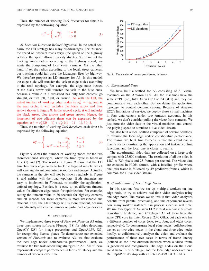
length, focus, and angle), and in the actual scenario it usuallycaptures only one-way traffic flow. Thus, a two-way roadneeds two cameras located on each side of the road. In thiscase, we assume a simple and regular road topology whereall roads are two-way and monitored by cameras (see Figure8). For a vehicle-tracking task, we present two diffusionmodels for task scheduling: distance-related diffusion (DD)and location-direction-related diffusion (LD). With both, weassume that a task will be sent to the edge node nearest to thekidnapping location with a fleeing direction. Thus, the numberof initialization camera is n0 = 1. For convenience, we choosethe first crossing of the fleeing direction as the initial point fordiffusing. Once the targeted vehicle is found, it will be resetso that only one edge node receives this task. For simplicity,we consider all cameras to have the same value of timeoutfor diffusing a task. The black arrow indicates the kidnappinglocation and driving direction.
1) Distance-Related Diffusion: A DD strategy, as the sim-plest strategy, diffuses the task according to the distance fromwhere the kidnapping occurred. For example, the trackingarea’s radius will increase by a fixed number as time passes.For the topology in Figure 8, the Task Receiver will send thetask to seven other neighboring cameras based on its directionwhen diffusing a task. As Figure 8 shows, the camera at theblack arrow will transfer the task to the cameras in the areaenclosed by the blue dashed square. Then, in next cycle, allcameras in green square will execute the task. According tothe rule of diffusion, we see that the increased cameras are alllocated between two squares as the blue and green squares.Hence, the increment of two adjacent times can be expressedby the equation ∆D
t = sr(2t − 1), t ≥ 2, where s definedas the side numbers of the square is 4, and r defined as thecameras of each side is 2.
IEEE INTERNET OF THINGS JOURNAL, VOL. 14, NO. 8, AUGUST 2018 10
Thus, the number of working Task Receivers for time t isexpressed by the following equation:
nDt =
{n0, t = 0
srt2, t > 0(1)
2) Location-Direction-Related Diffusion: In the actual sce-nario, the DD strategy has many disadvantages. For instance,the speed on different roads varys (the speed on the highwayis twice the speed allowed on city streets). So, if we set thetracking area’s radius according to the highway speed, wewaste the computing of local street cameras. On the otherhand, if set the radius according to the local, street cameras,our tracking could fail once the kidnapper flees by highway.We therefore propose an LD strategy for A3. In this model,the edge node will transfer the task to edge nodes accordingto the road topology. For example, the edge node locatedat the black arrow will transfer the task to the blue ones,because a vehicle in a crossroad has only four choices: gostraight, or turn left, right, or around. As with the DD, theinitial number of working edge nodes is nL
0 = n0, and inthe next cycle, it will includes the black arrow and bluearrows shown in Figure 8. In the second cycle, it will includesthe black arrow, blue arrows and green arrows. Hence, theincrement of two adjacent times can be expressed by theequation ∆L
t = s r2 (2t− 1) + s r
2 (2(t− 1) − 1), t ≥ 3.Thus, the number of working Task Receivers each time t is
expressed by the following equation:
nLt =
n0, t = 0n0 + s r
2 , t = 1srt2 − srt + s r
2 , t ≥ 2(2)
Figure 9 shows the number of working nodes for the twoaforementioned strategies, where the time cycle is based onEqs. (1) and (2). The results in Figure 9 show that the LDlaunches fewer edge nodes to track the targeted vehicle, whichwill save significant computing resources and energy. Actually,the cameras in the city will not be shown regularly in Figure8, and neither will the road topology. Both strategies areeasy to implement in Firework, to modify the application-defined topology. Besides, it is easy to set different timeoutvalues for different edge nodes for optimization. For example,setting the timeout value to 30 seconds for highway camerasand 60 seconds for local cameras is more reasonable andefficient. Thus, the LD strategy will is more efficient, becauseit significantly reduces the number of participant edge devices.
V. EVALUATION
We implemented three types of Firework.Node on A3 usingthree open source software: FFmpeg [38] for video decoding,OpenCV [28] for image processing and OpenALPR [27]for recognizing license plates. To demonstrate our extendedversion of Firework and to evaluate A3, we first evaluatethe local edge nodes’ collaborative performance. Then, weevaluate the two task-scheduling strategies in A3. All of theseexperiments compare performance in terms of latency and thenumber of workers over time.
0
50
100
150
200
250
300
350
400
450
0 1 2 3 4 5 6 7
Wor
king
Edg
e N
umbe
rs
Diffusion Cycles
DD algorithm
LD algorithm
Fig. 9. The number of camera participants, in theory.
A. Experimental Setup
We have built a testbed for A3 consisting of 81 virtualmachines on the Amazon EC2. All the machines have thesame vCPU (i.e., Intel Xeon CPU at 2.4 GHz) and they cancommunicate with each other. But we define the applicationtopology, to control communications. Because of AmazonEC2’s limitations of service, we deploy these virtual machinesin four data centers under two Amazon accounts. In thistestbed, we don’t consider pulling the video from cameras. Wejust store the video data in the virtual machines and controlthe playing speed to simulate a live video stream.
We also built a local testbed comprised of several desktops,to evaluate the local edge nodes’ collaborative performance.The reason we built two testbeds is that the cloud one ismainly for demonstrating the application and task-schedulingfunctions, and the local one is closer to reality.
The experimental video data are collected on a large-scalecampus with 25,000 students. The resolution of all the video is1280 × 720 pixels and 25 frames per second. The video dataare encoded in H.264 format, with a baseline profile whereone intra-frame is followed by 49 predictive-frames, which iscommon for a live video stream.
B. Collaboration of Local Edge Nodes
In this section, first we set up multiple workers on oneedge node, to try to achieve real-time video analytics usingone edge node. The reason we do this is that video analyticsbenefits from parallel processing, and this experiment revealshow many worker instances can process video in real time.We use four types of Amazon EC2 virtual machines: t2.small,t2.medium, t2.xlarge, and t2.2xlarge. All of them have thesame CPU core (an Intel Xeon at 2.40 GHz), but each one hasa different number of cores (one, two, four, and eight cores,respectively). To demonstrate local edge nodes’ collaboration,we set up two edge nodes in the cloud and three edge nodeslocally, to collaboratively analyze the video and evaluate theperformance of these two cases in terms of frame latency(defined as the time duration between when a video frameis generated and recognized). The edge nodes on the cloudare Amazon EC2 t2.xlarge, and the local edge nodes are on aDell OptiPlex desktop with an Intel i5-4590 at 3.3 GHz.
IEEE INTERNET OF THINGS JOURNAL, VOL. 14, NO. 8, AUGUST 2018 11
0
5
10
15
20
25
1 2 3 4 5 6 7 8 9
Fra
me
Lat
ency
(s)
Frame's Playing Time (s)
2 LPR Workers
3 LPR Workers
4 LPR Workers
5 LPR Workers
(a) AWS EC2 t2.small.
0
10
20
30
40
50
1 6 11 16 21
Fra
me
Lat
ency
(s)
Frame's Playing Time (s)
2 LPR Workers
3 LPR Workers
4 LPR Workers
5 LPR Workers
(b) AWS EC2 t2.medium.
0
5
10
15
20
25
30
35
40
1 6 11 16 21 26 31 36
Fra
me
Lat
ency
(s)
Frame's Playing Time (s)
2 LPR Workers
3 LPR Workers
4 LPR Workers
5 LPR Workers
(c) AWS EC2 t2.xlarge.
0
5
10
15
20
25
30
35
40
1 6 11 16 21 26 31 36
Fra
me
Lat
ency
(s)
Frame's Playing Time (s)
2 LPR Workers
3 LPR Workers
4 LPR Workers
5 LPR Workers
(d) AWS EC2 t2.2xlarge.
Fig. 10. Frame latency over time in different types of AWS nodes withdifferent numbers of LPR workers .
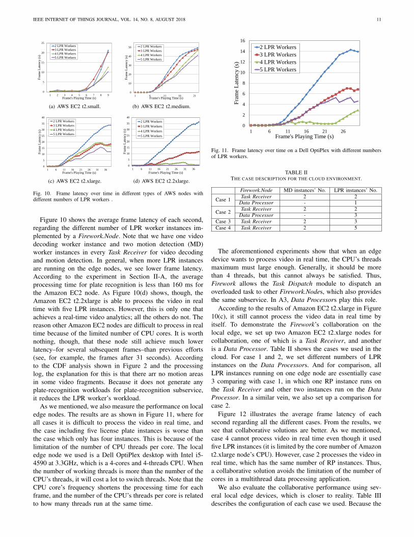
Figure 10 shows the average frame latency of each second,regarding the different number of LPR worker instances im-plemented by a Firework.Node. Note that we have one videodecoding worker instance and two motion detection (MD)worker instances in every Task Receiver for video decodingand motion detection. In general, when more LPR instancesare running on the edge nodes, we see lower frame latency.According to the experiment in Section II-A, the averageprocessing time for plate recognition is less than 160 ms forthe Amazon EC2 node. As Figure 10(d) shows, though, theAmazon EC2 t2.2xlarge is able to process the video in realtime with five LPR instances. However, this is only one thatachieves a real-time video analytics; all the others do not. Thereason other Amazon EC2 nodes are difficult to process in realtime because of the limited number of CPU cores. It is worthnothing, though, that these node still achieve much lowerlatency–for several subsequent frames–than previous efforts(see, for example, the frames after 31 seconds). Accordingto the CDF analysis shown in Figure 2 and the processinglog, the explanation for this is that there arr no motion areasin some video fragments. Because it does not generate anyplate-recognition workloads for plate-recognition subservice,it reduces the LPR worker’s workload.
As we mentioned, we also measure the performance on localedge nodes. The results are as shown in Figure 11, where forall cases it is difficult to process the video in real time, andthe case including five license plate instances is worse thanthe case which only has four instances. This is because of thelimitation of the number of CPU threads per core. The localedge node we used is a Dell OptiPlex desktop with Intel i5-4590 at 3.3GHz, which is a 4-cores and 4-threads CPU. Whenthe number of working threads is more than the number of theCPU’s threads, it will cost a lot to switch threads. Note that theCPU core’s frequency shortens the processing time for eachframe, and the number of the CPU’s threads per core is relatedto how many threads run at the same time.
0
2
4
6
8
10
12
14
16
1 6 11 16 21 26
Fra
me
Lat
ency
(s)
Frame's Playing Time (s)
2 LPR Workers
3 LPR Workers
4 LPR Workers
5 LPR Workers
Fig. 11. Frame latency over time on a Dell OptiPlex with different numbersof LPR workers.
TABLE IITHE CASE DESCRIPTION FOR THE CLOUD ENVIRONMENT.
Firework.Node MD instances’ No. LPR instances’ No.
Case 1 Task Receiver 2 2Data Processor - 1
Case 2 Task Receiver 2 2Data Processor - 3
Case 3 Task Receiver 2 3Case 4 Task Receiver 2 5
The aforementioned experiments show that when an edgedevice wants to process video in real time, the CPU’s threadsmaximum must large enough. Generally, it should be morethan 4 threads, but this cannot always be satisfied. Thus,Firework allows the Task Dispatch module to dispatch anoverloaded task to other Firework.Nodes, which also providesthe same subservice. In A3, Data Processors play this role.
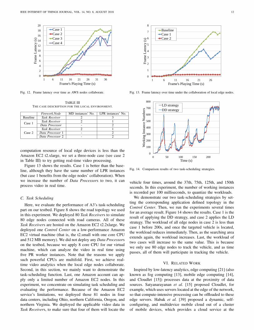
According to the results of Amazon EC2 t2.xlarge in Figure10(c), it still cannot process the video data in real time byitself. To demonstrate the Firework’s collaboration on thelocal edge, we set up two Amazon EC2 t2.xlarge nodes forcollaboration, one of which is a Task Receiver, and anotheris a Data Processor. Table II shows the cases we used in thecloud. For case 1 and 2, we set different numbers of LPRinstances on the Data Processors. And for comparison, allLPR instances running on one edge node are essentially case3 comparing with case 1, in which one RP instance runs onthe Task Receiver and other two instances run on the DataProcessor. In a similar vein, we also set up a comparison forcase 2.
Figure 12 illustrates the average frame latency of eachsecond regarding all the different cases. From the results, wesee that collaborative solutions are better. As we mentioned,case 4 cannot process video in real time even though it usedfive LPR instances (it is limited by the core number of Amazont2.xlarge node’s CPU). However, case 2 processes the video inreal time, which has the same number of RP instances. Thus,a collaborative solution avoids the limitation of the number ofcores in a multithread data processing application.
We also evaluate the collaborative performance using sev-eral local edge devices, which is closer to reality. Table IIIdescribes the configuration of each case we used. Because the
IEEE INTERNET OF THINGS JOURNAL, VOL. 14, NO. 8, AUGUST 2018 12
0
2
4
6
8
10
12
14
16
18
20
1 6 11 16 21 26 31 36
Fra
me
Lat
ency
(s)
Frame's Playing Time (s)
Case 1
Case 2
Case 3
Case 4
Fig. 12. Frame latency over time as AWS nodes collaborate.
TABLE IIITHE CASE DESCRIPTION FOR THE LOCAL ENVIRONMENT.
Firework.Node MD instances’ No. LPR instances’ No.Baseline Task Receiver 2 3
Case 1 Task Receiver 2 1Data Processor - 2
Case 2Task Receiver 2 1
Data Processor 1 - 2Data Processor 2 - 2
computation resource of local edge devices is less than theAmazon EC2 t2.xlarge, we set a three-node case (see case 2in Table III) to try getting real-time video processing.
Figure 13 shows the results. Case 1 is better than the base-line, although they have the same number of LPR instances(but case 1 benefits from the edge nodes’ collaboration). Whenwe increase the number of Data Processors to two, it canprocess video in real time.
C. Task Scheduling
Here, we evaluate the performance of A3’s task-schedulingpart on our testbed. Figure 8 shows the road topology we usedin this experiment. We deployed 80 Task Receivers to simulate80 edge nodes connected with road cameras. All of theseTask Receivers are hosted on the Amazon EC2 t2.2xlarge. Wedeployed one Control Center on a low-performance AmazonEC2 virtual machine (that is, the t2.small with one core CPUand 512 MB memory). We did not deploy any Data Processorson the testbed, because we apply 8 core CPU for our virtualmachine, which can analyze the video in real time usingfive PR worker instances. Note that the reasons we applysuch powerful CPUs are multifold. First, we achieve real-time video analytics when the local edge nodes collaborate.Second, in this section, we mainly want to demonstrate thetask-scheduling function. Last, one Amazon account can ap-ply only a limited number of Amazon EC2 nodes. In thisexperiment, we concentrate on simulating task scheduling andevaluating the performance. Because of the Amazon EC2service’s limitations, we deployed those 81 nodes in fourdata centers, including Ohio, northern California, Oregon, andnorthern Virginia. We deployed the applicable video data inTask Receivers, to make sure that four of them will locate the
0
1
2
3
4
5
6
7
8
1 6 11 16 21 26
Fra
me
Lat
ency
(s)
Frame's Playing Time (s)
Baseline
Case 1
Case 2
Fig. 13. Frame latency over time under the collaboration of local edge nodes.
0
100
200
300
400
500
600
700
800
0 50 100 150 200
Wo
rkin
g I
nst
ance
Nu
mb
ers
Time (s)
LD strategy
DD strategy
Fig. 14. Comparison results of two task-scheduling strategies.
vehicle four times, around the 37th, 75th, 125th, and 150thseconds. In this experiment, the number of working instancesis recorded per 100 milliseconds, to quantize the workloads.
We demonstrate our two task-scheduling strategies by set-ting the corresponding application defined topology in theControl Center. Then, we run the experiments several timesfor an average result. Figure 14 shows the results. Case 1 is theresult of applying the DD strategy, and case 2 applies the LDstrategy. The workload of all edge nodes in case 2 is less thancase 1 before 200s, and once the targeted vehicle is located,the workload reduces immediately. Then, as the searching areaextends again, the workload increases. Last, the workload oftwo cases will increase to the same value. This is becausewe only use 80 edge nodes to track the vehicle, and as timepasses, all of them will participate in tracking the vehicle.
VI. RELATED WORK
Inspired by low-latency analytics, edge computing [21] (alsoknown as fog computing [13], mobile edge computing [14],and Cloudlet [15]) processes data at the proximity of datasources. Satyanarayanan et al. [15] proposed Cloudlet, forexample, which uses servers located at the edge of the network,so that compute-intensive processing can be offloaded to theseedge servers. Habak et al. [39] proposed a dynamic, self-configuring, and multidevice mobile cloud out of a clusterof mobile devices, which provides a cloud service at the

IEEE INTERNET OF THINGS JOURNAL, VOL. 14, NO. 8, AUGUST 2018 13
edge. Fernando et al. [40] also proposed a similar cloud ofmobile devices. Saurez et al. [41] proposed a programminginfrastructure for the geodistributed computational continuumrepresented by fog nodes and the cloud, called Foglets. Fire-work differs from each of these systems, because it leveragesnot only mobile devices and the cloud, but also edge nodesto complete tasks collaboratively; the other aforementionedsystems are not for large-scale data processing and sharingamong multiple stakeholders.
As a killer application, several edge video analytics plat-forms have been proposed. Ananthanarayanan et al. [42]present a geodistributed framework for large-scale video an-alytics, which meets the strict requirements of real time. Itcarries out different computation modules using computervision by leveraging the public cloud, private clouds, andedge nodes. The difference between Firework and Anantha-narayanan’s work is that our work expands data sharing,along with attached computing modules (such as functionsin Firework.View) and programming interfaces are providedfor developers to build their application on edges and thecloud. Wang et al. [43] proposed a real-time face recognitionand tracking framework, called OpenFace, which also usededge computing to analyze live video. To protect privacy,OpenFace selectively blurs faces in video data, dependingon user-specific privacy policies. However, OpenFace onlyconsiders edge nodes. In our work, Firework and A3 leverageboth edge nodes and the cloud.
Zhang et al. [44] proposed a real-time video analyticsplatform, called VideoStorm, which leverages large clusters.It pushes all the video to clusters, and it has prohibitive costs.Our system use edge nodes to reduce costs in terms of latencyand network bandwidth. Yi et al. [45] proposed a latency-aware video analytics platform, called LAVEA. In LAVEA, thevideo data will be pushed to an edge-front node and each videoframe will be decoded and analyzed at other local edge nodes.This is similar to the collaboration of local edges. They alsoproposed several scheduling strategies to reduce latency. Aswith OpenFace, it only leverages edge nodes. Long et al. [46]proposed an edge computing framework for cooperative videoprocessing in the IoT domain. They use mobile devices asedges to enhance the computing power and network qualityby multiple uploading paths. Grassi et al. [47] proposed anapplication called ParkMaster, which detects parking spacesand reports vacant ones to the cloud for sharing this informa-tion with other people. It uses smartphones as edge devices inthe vehicle for detection. Because detection algorithms usuallycost much less than the recognition algorithms, smartphonescan process the video in real time.
VII. CONCLUSION
In this paper, we investigated the barriers of designingand implementing a distributed collaborative execution on theedge, such as a real-time vehicle-tracking application thatimproves the AMBER Alert system significantly. To attackthese barriers, we extended a big data processing and sharingframework in an edge-cloud environment, to support collabo-ration of local edge nodes and a customizable task-scheduling
scheme. Inspired by a real project (Project Green Light inDetroit), we abstracted out the network model, applying inA3. Based on Firework’s extensions, we implemented theAMBER Alert Assistant (A3), which supports different trackingstrategies. Then, we evaluated this application’s performances.The results show that A3 can analyze video streams in realtime by collaborating with several edge nodes, and the pro-posed location-direction-related task-scheduling strategy (LD)is more efficient at controlling the search area for vehicletracking. This demonstrates that A3 is ready to deploy on topof Project Green Light, and we believe A3 will improve theAMBER Alert.
Currently, Firework does not provide an interface to adjustthe deployment plan, so A3 cannot dynamically adjust the dif-fusion rate. This is helpful in a real scenario, considering roadconditions. For future work, we will design and implementsuch module. Besides, an elastic message queue module isalso our future work, which is able to dynamically launch thebest suitable message queue system for each edge device anda lightweight inner message queue for modules in Firework.
ACKNOWLEDGMENT
This work is supported in part by National Science Foun-dation (NSF) grant CNS-1741635, and Qingyang Zhang andHong Zhong are in part supported by National Science Foun-dation of China (No. 61572001) and Key Technology R&DProgram of Anhui Province (1704d0802193). The authors arevery grateful to the anonymous referees for their detailedcomments and suggestions regarding this paper.
REFERENCES
[1] M. Armbrust, A. Fox, R. Griffith, A. D. Joseph, R. Katz, A. Konwinski,G. Lee, D. Patterson, A. Rabkin, I. Stoica et al., “A view of cloudcomputing,” Communications of the ACM, vol. 53, no. 4, pp. 50–58,2010.
[2] S. Ghemawat, H. Gobioff, and S.-T. Leung, “The google file system,”in ACM SIGOPS operating systems review, vol. 37, no. 5. ACM, 2003,pp. 29–43.
[3] K. Shvachko, H. Kuang, S. Radia, and R. Chansler, “The hadoopdistributed file system,” in Proceedings of IEEE 26th Symposium onMass Storage Systems and Technologies (MSST). IEEE, 2010, pp. 1–10.
[4] (2017, Feb.) Apache storm. [Online]. Available: https://storm.apache.org/
[5] M. Zaharia, M. Chowdhury, M. J. Franklin, S. Shenker, and I. Stoica,“Spark: cluster computing with working sets,” in Proceedings of the 2ndUSENIX Conference on Hot Topics in Cloud Computing, vol. 10, 2010,p. 10.
[6] M. Zaharia, T. Das, H. Li, T. Hunter, S. Shenker, and I. Stoica,“Discretized streams: Fault-tolerant streaming computation at scale,”in Proceedings of the 24th ACM Symposium on Operating SystemsPrinciples. ACM, 2013, pp. 423–438.
[7] Q. Zhang, Y. Song, R. Routray, and W. Shi, “Adaptive block and batchsizing for batched stream processing system,” in Proceedings of IEEEInternational Conference on Autonomic Computing (ICAC), July 2016,pp. 35–44.
[8] J. Dean and S. Ghemawat, “Mapreduce: simplified data processing onlarge clusters,” Communications of the ACM, vol. 51, no. 1, pp. 107–113,2008.
[9] D. E. Culler, “The once and future internet of everything,” GetMobile:Mobile Computing and Communications, vol. 20, no. 3, pp. 5–11, 2017.
[10] (2017, Feb.) First workshop on video analytics in public safety.[Online]. Available: https://www.nist.gov/sites/default/files/documents/2017/01/19/ir 8164.pdf

IEEE INTERNET OF THINGS JOURNAL, VOL. 14, NO. 8, AUGUST 2018 14
[11] (2016, Apr.) Cisco global cloud index: Forecast and methodology20142019 white paper. [Online]. Available: http://www.cisco.com/c/en/us/solutions/collateral/service-provider/global-cloud-index-gci/Cloud
[12] D. Evans, “The internet of things: How the next evolution of the internetis changing everything,” CISCO white paper, vol. 1, no. 2011, pp. 1–11,2011.
[13] F. Bonomi, R. Milito, J. Zhu, and S. Addepalli, “Fog computing and itsrole in the internet of things,” in Proceedings of the first edition of theMCC workshop on Mobile Cloud Computing. ACM, 2012, pp. 13–16.
[14] M. Patel, B. Naughton, C. Chan, N. Sprecher, S. Abeta, A. Neal et al.,“Mobile-edge computing introductory technical white paper,” WhitePaper, Mobile-edge Computing (MEC) industry initiative, 2014.
[15] M. Satyanarayanan, P. Bahl, R. Caceres, and N. Davies, “The case forvm-based cloudlets in mobile computing,” Pervasive Computing, vol. 8,no. 4, pp. 14–23, 2009.
[16] M. Satyanarayanan, P. Simoens, Y. Xiao, P. Pillai, Z. Chen, K. Ha,W. Hu, and B. Amos, “Edge analytics in the internet of things,” IEEEPervasive Computing, vol. 14, no. 2, pp. 24–31, 2015.
[17] W. Hu, B. Amos, Z. Chen, K. Ha, W. Richter, P. Pillai, B. Gilbert,J. Harkes, and M. Satyanarayanan, “The case for offload shaping,” inProceedings of the 16th International Workshop on Mobile ComputingSystems and Applications. ACM, 2015, pp. 51–56.
[18] M. Satyanarayanan, “A brief history of cloud offload: A personal journeyfrom odyssey through cyber foraging to cloudlets,” GetMobile: MobileComputing and Communications, vol. 18, no. 4, pp. 19–23, 2015.
[19] M. Satyanarayanan, R. Schuster, M. Ebling, G. Fettweis, H. Flinck,K. Joshi, and K. Sabnani, “An open ecosystem for mobile-cloud con-vergence,” IEEE Communications Magazine, vol. 53, no. 3, pp. 63–70,2015.
[20] S. Agarwal, M. Philipose, and P. Bahl, “Vision: the case for cellularsmall cells for cloudlets,” in Proceedings of the fifth internationalworkshop on Mobile cloud computing & services. ACM, 2014, pp.1–5.
[21] W. Shi, J. Cao, Q. Zhang, Y. Li, and L. Xu, “Edge computing: Visionand challenges,” IEEE Internet of Things Journal, vol. 3, no. 5, pp.637–646, 2016.
[22] K. Pulli, A. Baksheev, K. Kornyakov, and V. Eruhimov, “Real-timecomputer vision with opencv,” Communications of the ACM, vol. 55,no. 6, pp. 61–69, 2012.
[23] Q. Zhang, X. Zhang, Q. Zhang, W. Shi, and H. Zhong, “Firework: Bigdata sharing and processing in collaborative edge environment,” in 2016Fourth IEEE Workshop on Hot Topics in Web Systems and Technologies(HotWeb), Oct 2016, pp. 20–25.
[24] Q. Zhang, Q. Zhang, W. Shi, and H. Zhong, “Firework: Data processingand sharing for hybrid cloud-edge analytics,” Technical Report MIST-TR-2017-002, 2017.
[25] (2017, Mar.) Amber alert. [Online]. Available: https://en.wikipedia.org/wiki/AMBER Alert
[26] (2017, Mar.) Project green light. [Online]. Available: http://www.greenlightdetroit.org/
[27] (2017, Mar.) Openalpr. [Online]. Available: https://github.com/openalpr/openalpr
[28] (2017, Mar.) Opencv. [Online]. Available: http://www.opencv.org/[29] (2017, Mar.) Docker. [Online]. Available: https://www.docker.com/[30] (2017, Mar.) Openstack. [Online]. Available: http://www.openstack.org/[31] (2017, Mar.) Vmware. [Online]. Available: https://www.vmware.com/[32] (2016, Sep.) etcd. [Online]. Available: https://github.com/coreos/etcd[33] (2017, Mar.) Introducing json. [Online]. Available: http://www.json.org/[34] L. Guo, C. Zhang, J. Sun, and Y. Fang, “Paas: A privacy-preserving
attribute-based authentication system for ehealth networks,” in 2012IEEE 32nd International Conference on Distributed Computing Systems,June 2012, pp. 224–233.
[35] J. Shao, R. Lu, and X. Lin, “Fine-grained data sharing in cloudcomputing for mobile devices,” in 2015 IEEE Conference on ComputerCommunications (INFOCOM), April 2015, pp. 2677–2685.
[36] U. Hunkeler, H. L. Truong, and A. Stanford-Clark, “Mqtt-s: A pub-lish/subscribe protocol for wireless sensor networks,” in CommunicationSystems Software and Middleware and Workshops, 2008. COMSWARE2008. 3rd International Conference on, Jan 2008, pp. 791–798.
[37] J. Kreps, N. Narkhede, J. Rao et al., “Kafka: A distributed messagingsystem for log processing,” in Proceedings of the NetDB, 2011, pp. 1–7.
[38] (2017, Mar.) Ffmpeg. [Online]. Available: https://ffmpeg.org/[39] K. Habak, M. Ammar, K. A. Harras, and E. Zegura, “Femto clouds:
Leveraging mobile devices to provide cloud service at the edge,”in Proceedings of the IEEE 8th International Conference on CloudComputing. IEEE, 2015, pp. 9–16.
[40] N. Fernando, S. W. Loke, and W. Rahayu, “Computing with nearbymobile devices: a work sharing algorithm for mobile edge-clouds,” IEEETransaction on Cloud Computing, 2016.
[41] E. Saurez, K. Hong, D. Lillethun, U. Ramachandran, and B. Ottenwalder,“Incremental deployment and migration of geo-distributed situationawareness applications in the fog,” in Proceedings of the 10th ACM In-ternational Conference on Distributed and Event-based Systems. ACM,2016, pp. 258–269.
[42] G. Ananthanarayanan, P. Bahl, P. Bodk, K. Chintalapudi, M. Philipose,L. Ravindranath, and S. Sinha, “Real-time video analytics: The killerapp for edge computing,” Computer, vol. 50, no. 10, pp. 58–67, 2017.
[43] J. Wang, B. Amos, A. Das, P. Pillai, N. Sadeh, and M. Satyanarayanan,“A scalable and privacy-aware iot service for live video analytics,” inProceedings of the 8th ACM on Multimedia Systems Conference, ser.MMSys’17. New York, NY, USA: ACM, 2017, pp. 38–49.
[44] H. Zhang, G. Ananthanarayanan, P. Bodik, M. Philipose, P. Bahl, andM. J. Freedman, “Live video analytics at scale with approximation anddelay-tolerance.” in NSDI, 2017, pp. 377–392.
[45] S. Yi, Z. Hao, Q. Zhang, Q. Zhang, W. Shi, and Q. Li, “Lavea: Latency-aware video analytics on edge computing platform,” in Proceedings of2nd ACM/IEEE Symposium on Edge Computing (SEC), ser. SEC’17.New York, NY, USA: ACM, 2017.
[46] C. Long, Y. Cao, T. Jiang, and Q. Zhang, “Edge computing frameworkfor cooperative video processing in multimedia iot systems,” IEEETransactions on Multimedia, vol. PP, no. 99, pp. 1–1, 2017.
[47] G. Grassi, P. Bahl, J. Kyle, and G. Pau, “Parkmaster: An invehicle,edgebased video analytics service for detecting open parking spaces inurban environments,” in Proceedings of 2nd ACM/IEEE Symposium onEdge Computing (SEC), ser. SEC’17. New York, NY, USA: ACM,2017.
Qingyang Zhang received the B. Eng. degree incomputer science and technology from Anhui Uni-versity, China in 2014. He is currently a Ph.D. candi-date at Anhui University. He is also a visiting studentin Wayne State University. His research interestincludes edge computing, and security protocol forwireless network.
Quan Zhang received his Ph.D. degree in theDepartment of Computer Science at Wayne StateUniversity in 2018, and his M.S. degree in ComputerScience at Wayne State University in 2016. Nowhe is a Data Engineer at Salesforce. His researchinterests include Cloud Computing, Edge Comput-ing, Real-time Streaming Processing, and Energy-efficient Systems.
Weisong Shi is a Charles H. Gershenson Distin-guished Faculty Fellow and a professor of ComputerScience at Wayne State University. His research in-terests include Edge Computing, Computer Systems,energy-efficiency, and wireless health. He receivedhis BS from Xidian University in 1995, and Ph.D.from Chinese Academy of Sciences in 2000, both inComputer Engineering. He is a recipient of NationalOutstanding PhD dissertation award of China andthe NSF CAREER award. He is an IEEE Fellowand ACM Distinguished Scientist.
Hong Zhong received her B.S. degree in appliedmathematics in Anhui University, China, in 1986,and the Ph.D. degree in computer science and tech-nology from University of Science and Technologyof China (USTC), China, in 2005. Now she is aprofessor and Phd Advisor of Anhui University. Herresearch interests cover network and informationsecurity.