ice measurements by geosat radar altimetry€¦ · h. jay zwally, judy a. major, anita c. brenner,...
TRANSCRIPT

H. JAY ZWALLY, JUDY A. MAJOR, ANITA C. BRENNER, and ROBERT A. BINDSCHADLER
ICE MEASUREMENTS BY GEOSAT RADAR ALTIMETRY
The surface topography of the Greenland and Antarctic ice sheets is the principal ice parameter obtainable from satellite radar altimetry. The improved ability of the GEOSA T altimeter to follow irregular surfaces and its extended operation have greatly increased the available topographic data on ice sheets for the study of ice dynamics and the possible detection of changes in global ice volume.
INTRODUCTION
Radar altimeter signals from ice-covered land and ocean are more complex and variable than are signals from the open ocean. Also, the range to the surface varies much more from pulse to pulse along the satellite path because of the more irregular topography. Although GEOS-3 and Seasat radar altimeters were designed to measure relatively flat oceanic surfaces, data from both have been very useful for ice-sheet topography.1.2 Partly as a result of the analysis of Seasat data,
H. J. Zwall y and R.A . Bindschadl er are with the Oceans and Ice Branch, ASA/ Goddard Space Flight Celller, Greenbelt, ;VID 2077 1. J. A. :vtajor and and A. C. Brenner are with EG&G Washington Analytical Sen 'ice" Celll er, Inc., Lanham, :vtD 20706 .
improvements were made in the GEOSAT tracking method to follow more rapid range changes over irregular surfaces, thus leading to the acquisition of more data over the steeper and more undulated portions of the ice sheets. The separated spacing of orbital tracks (Fig. 1) and the IS-month duration of the geodetic mission also are principal factors in producing an excellent topographic data set on the portions of the Greenland and Antarctic ice sheets lying between 72°N and 72°S.
The GEOSA T data acquired over the ice sheets and the surrounding sea ice have been provided to NASA by the Navy for unclassified processing and analysis. In particular, each GEOSA T altimeter waveform is analyzed to correct the range values for leads and lags in the altimeter tracking circuit. Over sea ice, the charac-
G EOSA T ground tracks (110 data days)
69
en 66 Q)
~ OJ Q)
~ Q)
" Z .;:; ~
-5 0 z 62
<-. /~
/ .. \
59 / / '/ . / / /
40 West longitude (degrees)
Johns H opkins A PL Technical VigcSI. Volume 8. N um ber:: (1 987)
Figure 1-Ground tracks of GEOSAT over the Greenland ice sheet for 110 data days. Discontinuities in tracks represent locations where the altimeter lost track of the signal because of rapid variations in the range to surface. The density of coverage is about twice that of Seasat 's because of better orbital tracking and spacing.
251

Zwally et al.. - Ice MeaSlirelllel1rs by CEOSA T Radar A/rilllerry
teristics of the radar returns are quite different from those over the open ocean, allowing the data over sea ice to be separated from the ocean data. Changes in the signal characteristics over ice-covered ocean also have been used routinely by the Navy to map the edge of the polar sea-ice pack.
A principal glaciological objective of ice-elevation analysis is the detection of changes in ice-sheet elevation that can give a direct measure of changes in ice volume. Each year, approximately 3000 cubic kilometers of water is exchanged between the ocean and the ice sheets, a volume of exchange equivalent to the annual removal and replacement of 7 millimeters of water from the entire surface of the oceans. However, the present uncertainty in the mass balance between snowfall on the ice sheets and ice discharge or melting is at least 30 percent or about ± 2 millimeters per year of sea-level equivalent. 3 Consequently, the uncertainty in the present mass balance of the polar ice sheets contributes a significant uncertainty to the mass budget of the world's oceans and may be a factor in current sea-level change. The elevation data from GEOSA T combined with 1978 Seasat data may yield a direct measurement of ice-elevation change over portions of the ice sheets if relative uncertainties in the determination of the satellites' orbits can be resolved. Detailed ice-surface topography from radar altimetry also is used to determine the direction and magnitude of the ice flow and to map and monitor other features of the earth's ice masses.
SIGNAL CHARACTERISTICS FROM ICE
Radar reflections from ice surfaces generally are determined by the dielectric constant of the ice, the surface roughness, the larger scale geometry of the surface, and possibly subsurface scattering. Overall, the shapes of the GEOSA T and Seas at altimeter waveforms are quite similar, and the main characteristics of the GEOSA T radar signals from ice are similar to those deduced previously for Seas at. Like ocean waveforms, the initial rising ramp of the ice waveforms corresponds to reflections from the "pulse-limited" footprint, defined by the first part of the radar- wavefront intersection with the reflecting surface. The remaining part of the waveform corresponds to reflections as the wavefront intersection expands through the broader beam-limited footprint of the altimeter. 4
On snow-covered ice sheets, the large-scale geometry of the surface is the principal factor affecting the returned signal and the measured range. The geometry is defined by undulations of the surface over several kilometers, superimposed on a mean slope defined over tens of kilometers. The pulse-limited footprint, to which the range is measured, tends to be located at the point of the surface within the beam-limited footprint that is closest to the satellite and not at satellite nadir, unless the surface is flat. 5.6 Furthermore, multiple reflecting surfaces, located at almost equal ranges from the altimeter, occur frequently in contrast to the situation over relatively flat ocean. Over ice-covered ocean, mixtures of different ice types and open water also form multi-
252
pie reflecting surfaces within the beam of the altimeter. Thus, the general situation is characterized by one or more pulse-limited footprints lying within the beamlimited footprint of the radar altimeter.
Most of the ice-sheet surfaces consist of snow with a density of about 400 kilograms per cubic meter, underlain by firn (old snow) with gradually increasing density to solid ice at about 100 meters below the surface. The ice-sheet surface typically has irregularities varying from snow-drift features (sastrugi) with heights ranging from a few centimeters to meters, to undulations with heights of up to tens of meters over several kilometers, caused by the ice flow over bedrock. The altimeter waveforms (Fig. 2a) over the smoother portions of the snowcovered ice sheets are very similar to waveforms over ocean, but are somewhat weaker because of the smaller dielectri<;: constant of pure ice. The ice-sheet waveforms also have a characteristic shape indicating a diffuse reflecting surface. In general, the waveform shape (Fig. 2a) is quite variable mainly because of the undulations in the surface that affect the shape and location of the area from which reflection is received. 4
Most of the reflecting surface of sea ice is very flat, but it typically consists of mixtures of different ice types and open water. The ice is saline and has a high dielectric absorption near the surface. The sea-ice surface also is usually covered by several tens of centimeters of snow. Many waveforms from a complete sea-ice cover are sharply peaked (Fig. 2b), indicating a specular reflection from a mirror-like surface. In general, the mixture of sea-ice types and open water seen within a typical altimeter footprint gives multiple reflecting surfaces with significantly different reflecting properties and variable ranges from the altimeter. Consequently, many waveforms over sea ice actually are composites of a specular return and a diffuse return, indicating a mixture of ice and open water within the footprint. Although most of the sea-ice surface is very flat, particularly for newly formed ice, a fraction of the ice area usually is very rough because of the intermittent ridging of the ice during convergence of the ice pack. However, the specular character of the signals indicates that the smooth areas produce the dominant signal, thus making attempts to derive information on surface roughness unsuccessful.
The range from the altimeter to the surface is determined from the arrival time of the midpoint of the waveform' s rising ramp. However, the range recorded by the altimeter is determined by the location in time of the central gate. Deviations of the midpoint of the ramp from the central gate cause range errors for which a correction must be made. Over the relatively flat oceans, the altimeter tracking circuit is designed to maintain the midpoint of the ramp in the central gate. Over sloping and undulating surfaces, the change in range between successive waveforms (recorded every tenth of a second or about 670 meters along the subsatellite track) is too great for the altimeter to be able to maintain the waveform in the central position. When the deviation exceeds the number of gates, range measurements are not obtained until the altimeter repositions the gates to acquire the waveform.
Johns H opkins A PL Technica l Digesr, Volume 8, Number 2 (/987)
Zwally el al. - Ice Measurements by GEOSA T Radar A /till1 eny
500r(a~)------~--------------.---------------,,---------------.---------------.-------.
en
Ht = 2425 . 18 AGC = 37 .05
400 H y, = 9.00 T = 0.0 :.H = 1 .25
C 300 :J o u 200
100
2423 .59 36 .86
9 .00 0 .1 0 .83
2414 .50 36 .24
8 .00 0 .6 1.01
2391.69 36 .85
7.00 1.7 4 .33
o~~~~--L-__ ~~~~L--L __ ~~~~-L~ ____ ~~~~ __ l-__ ~~~L-~-L __ ~
1000r(b~)------.---.-----------.---------------,,---------------r---------------.-------.
800
~ 600 c :J o u 400
200
Ht = 56 .10 AGC = 43 .45 H,., = 0 .00 T = 0 .0 :'H = - 0 .10
55.92 48 .70
0 .00 4.3
- 0.84
O~ ____ ~~~ ____ -L ____ ~~ __ ~ __ ~L-__ ~~L--L ____ ~ ____ ~LL~L--=~ ____ -L~L-~~~
o 60 60 Gates 60 60 60
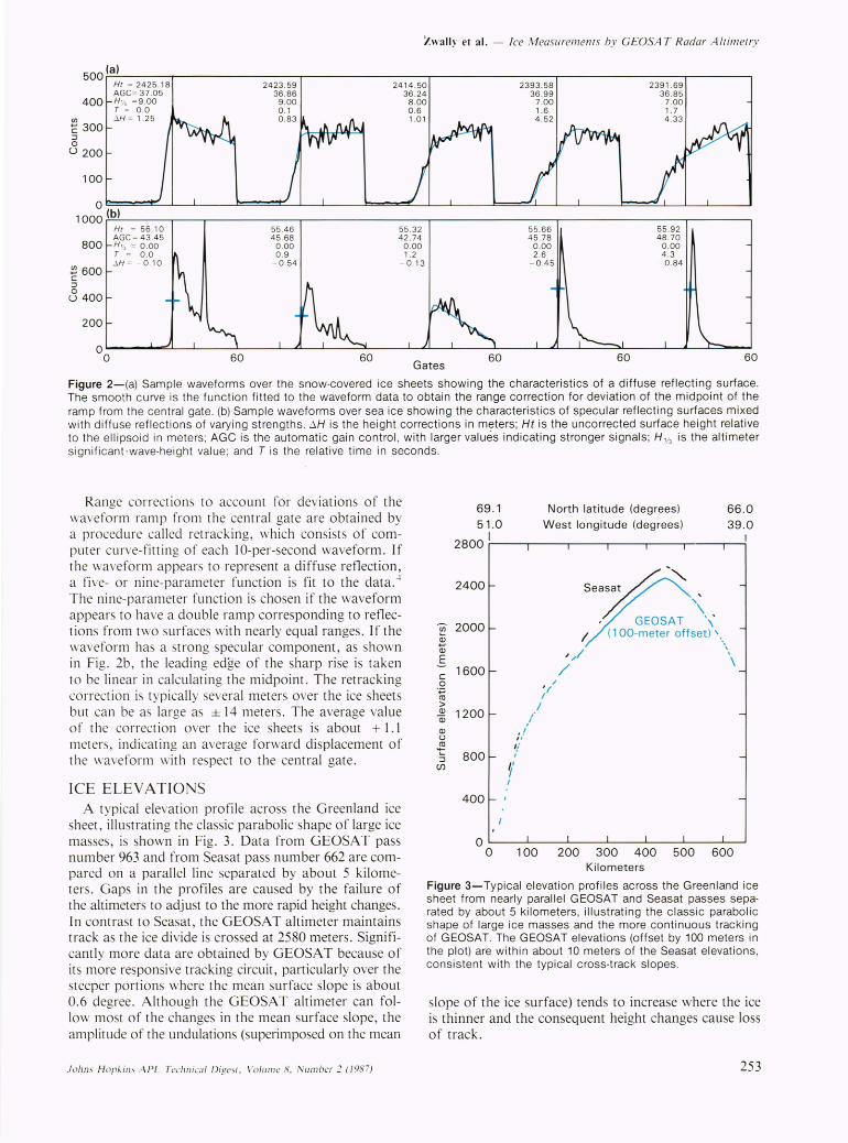
Figure 2-(a) Sample waveforms over the snow-covered ice sheets showing the characteristics of a diffuse reflecting surface. The smooth curve is the function fitted to the waveform data to obtain the range correction for deviation of the midpoint of the ramp from the central gate. (b) Sample waveforms over sea ice showing the characteristics of specular reflecting surfaces mixed with diffuse reflections of varying strengths. !J.H is the height corrections in meters; Ht is the uncorrected surface height relat ive to the ellipsoid in meters; AGe is the automatic gain control , with larger values indicating stronger signals; H'/3 is the altimeter significant-wave-height value ; and T is the relative time in seconds.
Range corrections to account for deviations of the waveform ramp from the central gate are obtained by a proced ure called retracking, which consists of computer curve-fitt ing of each 10-per-second waveform. If the waveform appears to represent a diffuse reflection, a five- or nine-parameter function is fit to the data. -l The nine-parameter function is chosen if the waveform appears to have a double ramp corresponding to reflections from two surfaces with nearly equal ranges . If the waveform has a strong specular component, as shown in Fig. 2b, the leading edge of the sharp ri se is taken to be linear in calculating the midpoint. The retracking correction is typically several meters over the ice sheets but can be as large as ± 14 meters . The average value of the correction over the ice sheets is about + 1.1 meters, indicating an average forward displacement of the wave form wi th respect to the central gate .
ICE ELEVATIONS A typical elevation profile across the Greenland ice
sheet, illustrating the classic parabolic shape of large ice masses, is shown in Fig. 3. Data from GEOSAT pass number 963 and from Seasat pass number 662 are compared on a parallel line separated by about 5 kilometers. Gaps in the profiles are caused by the failure of the altimeters to adjust to the more rapid height changes. In contrast to Seasat, the GEOSAT a ltimeter maintains track as the ice divide is crossed at 2580 meters. Significantly more data are obtained by GEOSA T because of its more responsive tracking circuit, particularly over the steeper portions where the mean surface slope is about 0.6 degree . Although the GEOSA T altimeter can fol low most of the changes in the mean surface slope, the amplitude of the undulations (superimposed on the mean
Johns H opkins APL T~chnica l Digesl. Vo lu me 8. Nu mber 2 (198 7)
69.1 51 .0
North latitude (degrees) 66.0 West longitude (degrees) 39.0
2800,1 ---.----,---~----.---,,--_.~
2400
en 2000 ~ Q)
E c: 1600 o
'';::::; co > Q)
Q)
Q)
u
-t ::J
(j)
1200
800
400
"
" :/ 1/ I
f I
,I
' / /
/
Seasat ~ -~ "
#:.-" \ , , GEOSAT \ I (1 OO-meter offset) \,
, / \ /
o L-__ -L ____ ~ ____ L_ __ -L ____ ~ __ ~ __ ~
o 100 200 300 400 500 600 Kilometers
Figure 3-Typical elevation profiles across the Greenland ice sheet from nearly parallel GEOSAT and Seasat passes separated by about 5 kilometers, illustrating the classic parabolic shape of large ice masses and the more continuous tracking of GEOSAT. The GEOSAT elevations (offset by 100 meters in the plot) are within about 10 meters of the Seasat elevations, consis tent with the typical cross-track slopes.
slope of the ice surface) tends to increase where the ice is thinner and the consequent height changes cause loss of track.
253
Zwally et al. - Ice Measurements by GEOSA T Radar A /timetry
As a measure of precision, the differences in elevations where passes cross over the same sub satellite point are examined. The standard deviation of the elevation difference at 17,161 crossovers on the Greenland ice sheet for 110 days of data is 1.61 meters, with a mean difference of - 0.50 meter between the descending and ascending passes. The comparable values at1235 Seasat/ Seasat crossovers, after adjustment for radial orbit errors by referencing the Seas at data to a sea-level reference surface, are a standard deviation of 1.06 meters and a mean difference of 0.14 meter. The larger standard deviation for GEOSAT is probably caused in part by residual radial orbit errors, which may be in the range of 0.5 to 1.0 meter, and in part by the inclusion of more crossovers for GEOSA T in the steeper and more undulating areas, where the precision is poorer. A preliminary analysis of the crossover differences between Seasat and GEOSA T at 8808 locations indicates that the surface elevation has increased between 1978 and 1985, but possible differences in the relative reference levels of the two data sets have not yet been eliminated.
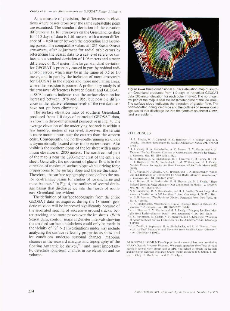
The surface elevation map of southern Greenland, produced from 110 days of retracked GEOSA T data, is shown in three-dimensional perspective in Fig. 4. The average elevation of the underlying bedrock is within a few hundred meters of sea level. However, the terrain is more mountainous near the eastern than the western coast. Consequently, the north-south-running ice divide is asymmetrically located closer to the eastern coast. Also visible is the southern dome of the ice sheet with a maximum elevation of 2800 meters. The north-central part of the map is near the 3200-meter crest of the entire ice sheet. Generally, the movement of glacier flow is in the direction of maximum surface slope with a driving force proportional to the surface slope and the ice thickness. 7
Therefore, the surface topography alone defines the major ice-drainage basins for studies of ice discharge and mass balance. 8 In Fig. 4, the outlines of several drainage basins that discharge ice into the fjords of southeast Greenland are evident.
The definition of surface topography from the entire GEOSAT data set acquired during the 18-month geodetic mission will be improved significantly because of the separated spacing of successive ground tracks, better tracking, and more passes over the ice sheets. (With Seasat data, contour maps at 2-meter intervals showing the detailed surface undulations could only be made in the vicinity of 72 0 N.) Investigations under. way include analyzing the surface-reflecting properties as snow and ice conditions undergo seasonal changes, mapping changes in the seaward margins and topography of the floating Antarctic ice shelves, 9- 11 and, most importantly, detecting long-term changes in ice elevation and ice volume.
254
Figure 4-A three-dimensional surface elevation map of southern Greenland produced from 110 days of retracked GEOSAT data (500-meter elevation for each color interval). The north-central part of the map is near the 3200-meter crest of the ice sheet. The surface slope indicates the direction of glacier flow. The north-south-running ice divide and the outlines of several drainage basins that discharge ice into the fjords of southeast Greenland are evident.
REFERENCES
I R. L. Brooks, W. J. Campbell , R. O. Ramseier, H. R. Stanley, and H. J . Zwally, " Ice Sheet Topography by Satellite Altimetry," Nature 274, 539-543 (1978).
2 H . J. bvally. R. A . Bindschadler, A. C. Brenner, T . V. Martin, and R. H . Thomas, " Surface Elevation Contours of Greenland and Antarctic Ice Sheets," 1. Geophys. Res. 88, 1589- 1596 (1983).
3 R. H. Thomas, B. A. Bindschadler, R. L. Cameron, F. D. Carsey, B. Holt, T. J. H ughes, C. W. I. Swithinbauk, I. M. Whillans, and H . J. Zwally, Salel/ire Remole Sensing for Ice Sheer Research , ASA Tech. Memo 86233 (1985).
"T. V. Manin, H . J. Zwally, A. C. Brenner, and R. A. Bindschadler, "Analys is and Retrack ing of Continental Ice Sheet Radar Altimeter Waveforms," 1. Geophys. Res. 88, 608-1616 (1983).
5 A. C. Brenner, R. A. Bindschadler, R. H . Thomas, and H. J . ZwaUy, "SlopeInduced Errors in Radar Altimetry Over Continental Ice Sheets," 1. Geophys. Res. 88, 161 7- 1623 (1983).
6 N. S. Gundestrup, R. A. Bindschadler, and H . J. Zwally,"Seasat Range Measurement Verified on a 3-D Ice Sheet ," Ann. Glaciology 8, 69-72 (1986) .
7 W. S. B. Paterson, The Physics of Glaciers, Pergan10n Press, New York , pp. 153- 157 (1981).
8 R. A. Bindschadler , " Jakobshavns Glacier Drainage Basin : A Balance Assessment, " 1. Geophys. Res. 89, 2066-2072 (1984).
9 R. H . Thomas, T . V. Martin, and H . J . Zwally, " Mapping Ice Sheet Margins from Radar-A ltimetry Data," Ann. Glaciology 4, 283- 288 (1983).
10 K. C. Partington, W. Cudlip , N. F. McIntyre, and S. King-Hele, "Mapping of Amery Ice Shelf Surface Features by Satellite Altimetry," A nn. Glaciology 9 (1987).
II H . J. Zwally, S. Stephenson, R. A . Bindschadler, and R. H . Thomas, " Antarctic Ice Shelf Boundaries and Elevations from Satellite Radar Altimetry," Ann. Glaciology 9 (1987).
ACK OWLEDGMENTS-Support for this research has been provided by NASA 's Oceanic P rocesses Program. We greatly appreciate the efforts of many people in several avy groups and at APL who helped us obtain the ice data and have given technical assistance . Special thanks are owed to S. Smith , T. Da\is, L. Choy, J . MacArthur, and C. C. Kilgus.
Johns H opkins APL Technical Digesl, Volume 8, Number 2 (198 7)