ibm totalstorage lto ultrium tape drive: scsi … totalstorage lto ultrium tape drive: scsi...
TRANSCRIPT
IBM TotalStorage LTO Ultrium
Tape Drive
SCSI Reference
GA32-0450-07
���


IBM TotalStorage LTO Ultrium
Tape Drive
SCSI Reference
GA32-0450-07
���
Note
Before using this manual and the product it supports, read the information under Appendix B, “Notices,” on page 291.
Eighth Edition (July 2007)
This edition applies to the IBM TotalStorage LTO Ultrium Tape Drive SCSI Reference and to all subsequent releases and
modifications unless otherwise indicated in new editions.
© Copyright International Business Machines Corporation 2002, 2003, 2004, 2005, 2006, 2007. All rights reserved.
US Government Users Restricted Rights – Use, duplication or disclosure restricted by GSA ADP Schedule Contract
with IBM Corp.
Read This First
This is the eighth edition of the IBM TotalStorage LTO Ultrium Tape Drive SCSI
Reference (July 2007).
Summary of Changes
Second Edition, April 2004
The following changes were made in this edition:
v Added features of the 3580 Tape Drive Models L23 and H23.
v Modified to show that the generation 2 drive code ignores the Page Control (PC)
field.
v Modified parameters and descriptions in Table 54 on page 58.
v Modified Table 55 on page 59 to show added support for TapeAlerts 51, 52, and
53 and to show removed claim support for flags 19, 35, and 38.
v Modified the Medium Type field definition in section “Mode Parameter Header”
on page 107.
v Modified sections“Mode Page 0Fh: Data Compression Mode Page” on page 114
and “Mode Page 10h: Sequential Access Device Configuration Page” on page 116
to reflect that now the Emerald drive’s behavior matches that of the Sapphire
drive.
v Modified the Text Generation value in Table 152 on page 157.
v Modified section Table 153 on page 158 to show that Medium Auxiliary Memory
parameters 1400h-17FFh of Application Specific Data can be written to Cartridge
Memory as long as space is available.
v Modified section“READ POSITION” on page 173 to correctly state the behavior
of the READ POSITION command after a READ type command.
v Modified section “SET CAPACITY (not Ultrium 1)” on page 234 to show that
Check Condition status is returned with Illegal Field in CDB (5/2400h) if the
Capacity Proportion Value of a new cartridge becomes smaller than 17.2 GB.
Third Edition, December 2004
The following changes were made in this edition:
v Added Generation 3 (Ultrium 3 Support).
v Added LTO Gen 3 log pages, as appropriate.
v Added support for IBM® TotalStorage® 3580 Tape Drive Models L33/L3H.
v Added support for IBM TotalStorage Ultrium 3 Tape Drive.
v Added support for IBM TotalStorage 400® GB Data Cartridge.
v Added new required items to Inquiry pages in the section entitled “INQUIRY”
on page 21.
v Changed values of BQue field and CmdQ field in the section entitled “Standard
Inquiry Data” on page 22.
v Added new log sense data and additional supported log pages (see “LOG
SENSE” on page 50).
v Replaced TapeAlert Log Parameters in Table 55 on page 59.
© Copyright IBM Corp. 2002, 2003, 2004, 2005, 2006, 2007 iii
v Created a mode page that can be saved and used to configure behavior changes
to a drive (see “Mode Page 2Fh: Behavior Configuration Mode Page” on page
131).
v Added speed matching and defined a byte field to be used to distinguish
between a full performance drive and a non-performance limited drive (see
“Sense Data Format” on page 187).
Fourth Edition, March 2005
The following changes were made in this edition:
v Added Fibre Channel support.
Fifth Edition, May 2006
The following changes were made in this edition:
v Added Space (16) command to Chapter 3.
v Added Chapter 8 Firmware Download.
Sixth Edition, December 2006
The following changes were made in this edition:
v Added additional sense values to Chapter 7, “Sense Keys and Additional Sense,”
on page 253
v Added support for the Tape Data Encryption Security Protocol of the Security
Protocol In and Security Protocol Out comands
Seventh Edition, June 2007
Information to update this edition was obtained from the following Functional
Change Request documents (FCRs):
v FCR 3056 - LTO Emulate WORM Additions
v FCR 3048 - LTO WORM Read Attribute Behavior
v FCR 3059r1 - Add support for Load_Unload Hold bit
v FCR 3078 - SPC-4 Set Timestamp and Report Timestamp
v FCR 3080 - Encryption Counters
v FCR 3089 - Component Revision Level Inquiry Page
v FCR 3096 - LTO TapeAlert 22 Clearing Behavior Change
v FCR 3097 - LTO Limit ERP
v FCR 3099 - LTO HH Changes
v FCR 3103 - New Thread_Unthread Additional Sense Code
v FCR 3104 - Log Pages 14h & 16h
v FCR 3105 - LTO Set Capacity - Return to LP4
v FCR 3106 - Log Page 11h on LUN 0
v FCR 3107 - Allow Read Attribute when CM Accessible
v FCR 3108 - LTO Read dump w strictly increasing offsets
v FCR 3109r1 - Send Diagnostic (Read Thermal Sensor)
v FCR 3112 - LTO4 (J2E Encryption Method)
v FCR 3121r2 - License Keys (LTO)(Internal with Inquiry Data)
v FCR 3122 - LTO LogPage 30h - Tape Usage Log Updates
v FCR 3123 - Component Revision Level Inquiry Page
v FCR 3124 - LTO Dead Media reporting (page 2F)
iv IBM TotalStorage LTO Ultrium Tape Drive: SCSI Reference
v FCR 3128 - LTO Log Page 31 Clarification
v FCR 3130 - LTO pSCSI U320 Support
v FCR 3132 - Mode Parameter Speed Field
Eighth Edition, July 2007
Information to update this edition was obtained from the following Functional
Change Request documents (FCRs):
v FCR 3133 - LTO Inquiry page C8h
v FCR 3136r0 - LTO ITD Pages (Entire Set)
v FCR 3112 - LTO 4 (J2E Encryption Method)
v FCR 3130 - LTO pSCSI U320 Support
v FCR 3131 - Direct Key Labels
v FCR 3139 - Mode Page 2F Cleanup for Pubs.
Read This First v

vi IBM TotalStorage LTO Ultrium Tape Drive: SCSI Reference
Contents
Read This First . . . . . . . . . . . iii
Summary of Changes . . . . . . . . . . . iii
Second Edition, April 2004 . . . . . . . . iii
Third Edition, December 2004 . . . . . . . iii
Fourth Edition, March 2005 . . . . . . . . iv
Fifth Edition, May 2006 . . . . . . . . . iv
Sixth Edition, December 2006 . . . . . . . iv
Seventh Edition, June 2007 . . . . . . . . iv
Eighth Edition, July 2007 . . . . . . . . . v
Tables . . . . . . . . . . . . . . . xi
Preface . . . . . . . . . . . . . . xv
Organization . . . . . . . . . . . . . . xv
Related Publications . . . . . . . . . . . xv
Chapter 1. Introduction . . . . . . . . 1
Supported Servers and Operating Systems . . . . 3
SCSI and Fibre Channel Attachment . . . . . 3
Supported Device Drivers . . . . . . . . . . 4
Supported Tape Cartridges . . . . . . . . . 5
Chapter 2. Summary of Drive Generation
Differences . . . . . . . . . . . . . 7
Differences in Command Timeout Values . . . . . 8
Command and Parameter differences between
generations . . . . . . . . . . . . . . 15
Data Changes Between Generations . . . . . . 15
Standard Inquiry Data . . . . . . . . . . 15
REPORT DENSITY SUPPORT Command . . . 15
Mode Pages . . . . . . . . . . . . . 16
READ POSITION Command . . . . . . . 16
Request Sense Changes . . . . . . . . . 16
Behavior Changes Between Generations . . . . . 16
Cartridge Eject for Errors . . . . . . . . . 16
Queueing Issues . . . . . . . . . . . . 16
Microcode Detection of Errors . . . . . . . . 16
Fencing Behavior . . . . . . . . . . . 16
Chapter 3. Command Support . . . . . 17
ERASE . . . . . . . . . . . . . . . . 20
INQUIRY . . . . . . . . . . . . . . . 21
Standard Inquiry Data . . . . . . . . . . 22
Supported Vital Product Data Page . . . . . 25
Firmware Designation Page (03h) . . . . . . 26
Mode Page Policy Page (87h) . . . . . . . 27
SCSI Ports Page (88h) . . . . . . . . . . 30
Sequential-Access Device Capabilities Page (B0h) 32
Drive Serial Numbers . . . . . . . . . . 33
Device Unique Configuration Data Page (C7h) . 34
Mode Parameter Default Settings Page (C8h) . . 37
Unit Serial Number Page . . . . . . . . . 39
Device Identification Page . . . . . . . . 40
Drive Component Revision Levels Pages . . . 44 45
LOAD/UNLOAD . . . . . . . . . . . . 45
LOCATE . . . . . . . . . . . . . . . 47
LOG SELECT . . . . . . . . . . . . . . 49
LOG SENSE . . . . . . . . . . . . . . 50
Log Page Format . . . . . . . . . . . 51
Log Page 00h: Supported Log Pages . . . . . 52
Log Page 02h: Write Error Counters . . . . . 55
Log Page 03h: Read Error Counters . . . . . 56
Log Page 06h: Non-Medium Errors (Not Ultrium
1 or Ultrium 2 non-RoHS) . . . . . . . . 57
Log Page 0Ch: Sequential Access Device Log . . 58
Log Page 2Eh: Tape Alert . . . . . . . . . 59
Log Page 11h: DT Device Status Log Page . . . 62
Log Page 14h: Device Statistics Log Page (Not
Ultrium 1 or 2) . . . . . . . . . . . . 69
Log Page 16h: Tape Diagnostic Data Log Page
(Not Ultrium 1 or 2) . . . . . . . . . . 71
Log Page 18h: Protocol-Specific Logical Unit Log
Page . . . . . . . . . . . . . . . . 74
Log Page 30h: Tape Usage Log . . . . . . . 77
Log Page 31h: Tape Capacity Log . . . . . . 79
Log Page 32h: Data Compression Log . . . . 80
Log Page 33h: Write Errors (Not Ultrium 1 or
Ultrium 2 non-RoHS) . . . . . . . . . . 81
Log Page 34h: Read Forward Errors (Not Ultrium
1 or Ultrium 2 non-RoHS) . . . . . . . . 83
Log Page 37h: Performance Characteristics
(Ultrium 4) . . . . . . . . . . . . . 85
Log Page 38h: Blocks/Bytes Transferred (Not
Ultrium 1 or Ultrium 2 non-RoHS) . . . . . 95
Log Page 39h: Host Port 0 Interface Errors (Not
Ultrium 1 or Ultrium 2 non-RoHS) . . . . . 97
Log Page 3Bh: Host Port 1 Interface Errors (Not
Ultrium 1 or Ultrium 2 non-RoHS) . . . . . 98
Log Page 3Dh: Subsystem Statistics (Not Ultrium
1 or Ultrium 2 non-RoHS) . . . . . . . . 99
Log Page 3Ch: Drive Usage Information . . . 102
MODE SELECT . . . . . . . . . . . . 103
MODE SENSE . . . . . . . . . . . . . 104
Mode Data Format . . . . . . . . . . 106
Mode Parameter Header . . . . . . . . 107
Mode Block Descriptor . . . . . . . . . 109
Mode Page 01h: Read-Write Error Recovery
Page . . . . . . . . . . . . . . . 110
Mode Page 02h: Disconnect/Reconnect Page . . 112
Mode Page 0Ah: Control Extension Mode Page 113
Mode Page 0Fh: Data Compression Mode Page 114
Mode Page 10h: Sequential Access Device
Configuration Page . . . . . . . . . . 116
Mode Page 18h: Protocol-Specific Logical Unit
Control Page . . . . . . . . . . . . 119
Mode Page 19h: Protocol Specific Port Control
Page . . . . . . . . . . . . . . . 120
Protocol Specific Port Control Page short format
(Ultra 320 attached drives only) . . . . . . 122
Negotiated Settings mode subpage . . . . . 123
© Copyright IBM Corp. 2002, 2003, 2004, 2005, 2006, 2007 vii
Report Transfer Capabilities mode subpage . . 125
Mode Page 1Ch: Information Exceptions Mode
Page . . . . . . . . . . . . . . . 126
Mode Page 1Dh: Medium Configuration Mode
Page . . . . . . . . . . . . . . . 127
Vendor-Specific Control Mode Page . . . . . 129
Mode Page 2Fh: Behavior Configuration Mode
Page . . . . . . . . . . . . . . . 131
Mode Page 3Dh: LEOT Mode Page (3Dh) (LTO
1 Only) . . . . . . . . . . . . . . 136
PERSISTENT RESERVE IN . . . . . . . . . 137
PERSISTENT RESERVE OUT . . . . . . . . 142
PREVENT/ALLOW MEDIUM REMOVAL . . . 146
READ . . . . . . . . . . . . . . . . 147
READ ATTRIBUTE . . . . . . . . . . . 149
Vendor-specific Medium Type Attributes . . . 151
Format for the Attribute Values Service Action 152
Format for the Attribute List Service Action . . 153
Format for the Volume List Service Action . . . 154
Format for the Partition List Service Action . . 155
Medium Auxiliary Memory . . . . . . . 156
READ BLOCK LIMITS . . . . . . . . . . 165
READ BUFFER . . . . . . . . . . . . . 166
Error Log Buffer (06h) . . . . . . . . . 170
World Wide Name Buffer (08h) . . . . . . 171
SCSI Log Buffer (07h) . . . . . . . . . 172
READ POSITION . . . . . . . . . . . . 173
RECEIVE DIAGNOSTIC RESULTS . . . . . . 176
RELEASE UNIT . . . . . . . . . . . . 177
REPORT DENSITY SUPPORT . . . . . . . . 178
REPORT LUNs . . . . . . . . . . . . . 183
REPORT SUPPORTED TASK MANAGEMENT
FUNCTIONS (Not LTO1) . . . . . . . . . 185
REPORT TIMESTAMP (Not LTO 1) . . . . . . 186
REQUEST SENSE . . . . . . . . . . . . 187
Sense Data Format . . . . . . . . . . 187
RESERVE UNIT . . . . . . . . . . . . 192
REWIND . . . . . . . . . . . . . . . 193
SECURITY PROTOCOL IN (SPIN) A2h . . . . . 194
Security Protocol In Pages (00h - Security
Protocol Information) . . . . . . . . . . 194
SECURITY PROTOCOL OUT (SPOUT) B5h . . . 203
Security Protocol Out Pages (20h - Tape Data
Encryption security protocol) . . . . . . . 203
SPOUT (20h:0010h) - Set Data Encryption . . . 204
Key-Associated Data (KAD) Descriptors . . . 206
SEND DIAGNOSTIC . . . . . . . . . . . 209
SIM Data Structure . . . . . . . . . . 210
MIM Data Structure . . . . . . . . . . 213
Self-Test . . . . . . . . . . . . . . 216
Post A Self Test Diagnostic . . . . . . . . 217
Post B Performance Diagnostic . . . . . . 218
Post C Media Test Diagnostic . . . . . . . 219
Post D Head Test Diagnostic . . . . . . . 221
Primary Port Wrap Test Diagnostic . . . . . 222
Force Dump . . . . . . . . . . . . . 223
Write Dump To Cartridge . . . . . . . . 224
Write Dump to Flash (EEPROM) . . . . . . 226
Clear FLASH Dump (EEPROM) . . . . . . 227
Set Traps . . . . . . . . . . . . . . 228
Remove Traps . . . . . . . . . . . . 229
Reset Drive . . . . . . . . . . . . . 231
SET CAPACITY (not Ultrium 1) . . . . . . . 234
SPACE . . . . . . . . . . . . . . . 236
TEST UNIT READY . . . . . . . . . . . 238
VERIFY . . . . . . . . . . . . . . . 239
WRITE . . . . . . . . . . . . . . . 240
WRITE ATTRIBUTE . . . . . . . . . . . 241
WRITE BUFFER . . . . . . . . . . . . 242
WRITE FILE MARKS . . . . . . . . . . . 244
Chapter 4. Error Sense Information 245
Sense Data . . . . . . . . . . . . . . 245
Sense Data Management . . . . . . . . . 245
Unit Attention Conditions . . . . . . . . . 245
Persistent Errors . . . . . . . . . . . . 246
Fencing Behavior . . . . . . . . . . . 246
Chapter 5. Implementation
Considerations . . . . . . . . . . . 249
Device Clocks . . . . . . . . . . . . . 249
Chapter 6. WORM BEHAVIORS . . . . 251
Conditions for Writing . . . . . . . . . . 251
Command Behavior When WORM Medium Has
Been Tampered With . . . . . . . . . . . 251
Chapter 7. Sense Keys and Additional
Sense . . . . . . . . . . . . . . . 253
Sense Key 0 (No Sense) . . . . . . . . . . 253
Sense Key 1 (Recovered Error) . . . . . . . . 253
Sense Key 2 (Not Ready) . . . . . . . . . 255
Sense Key 3 (Medium Error) . . . . . . . . 255
Sense Key 4 (Hardware or Firmware Error) . . . 257
Sense Key 5 (Illegal Request) . . . . . . . . 257
Sense Key 6 (Unit Attention) . . . . . . . . 259
Sense Key 7 (Data Protect) . . . . . . . . . 259
Sense Key 8 (Blank Check) . . . . . . . . . 260
Sense Key B (Aborted Command) . . . . . . 261
Sense Key D (Volume Overflow) . . . . . . . 261
Chapter 8. Device Hardware
Encryption (Ultrium 4) . . . . . . . 263
265
Chapter 9. Attachment Features . . . 265
Types of Interface Attachments . . . . . . . 265
Common Tape LUN Behaviors . . . . . . . 265
Power-On . . . . . . . . . . . . . 265
Reset Strategy . . . . . . . . . . . . 265
Abort Handling . . . . . . . . . . . 266
Multi-initiator Support . . . . . . . . . 268
Features of the Serial Attached SCSI (SAS)
Interface . . . . . . . . . . . . . . 268
Status Codes . . . . . . . . . . . . 268
Features of the SCSI Interface . . . . . . . . 269
LUN Identification . . . . . . . . . . 269
SPI Information Unit (Ultra 320 Attached drives
only) . . . . . . . . . . . . . . . 269
Bus Parity Errors (when using Data group
transfers) . . . . . . . . . . . . . . 269
viii IBM TotalStorage LTO Ultrium Tape Drive: SCSI Reference
Bus Parity Errors (when using Information unit
transfers) . . . . . . . . . . . . . . 270
Disconnect Strategy . . . . . . . . . . 270
Messages . . . . . . . . . . . . . . 271
Features of the Fibre Channel Interface . . . . . 275
Chapter 10. Firmware Download . . . 277
Identifying Level Hardware of Drive (Not Ultrium
1) . . . . . . . . . . . . . . . . . 277
Identifying the Level Hardware for which the
Firmware image is intended (Not Ultrium 1) . . . 279
Download Process . . . . . . . . . . . 279
Appendix A. ASN.1 Information (Used
for Encryption) . . . . . . . . . . . 281
ASN.1 [DER] Encoding Implementation . . . . 281
SEDK ASN.1 Format . . . . . . . . . . . 281
ASN.1 Standalone SEDK (SEDK only, clear, signed)
- Example . . . . . . . . . . . . . . 282
ASN.1 Standalone SEDK (SEDK only, dSK
encrypted, signed) - Example . . . . . . . . 283
EEDK ASN.1 Format . . . . . . . . . . . 284
xAK/xSK ASN.1 Format . . . . . . . . . 285
ASN.1 xAK/xSK Structure (clear, signed) -
Example . . . . . . . . . . . . . . . 286
Signing ASN.1 Format . . . . . . . . . . 287
ASN.1 Signing Information (clear, unsigned) -
Example . . . . . . . . . . . . . . . 288
ASN.1 Signing Information (eAK encrypted, dAK
signed) - Example . . . . . . . . . . . . 288
HMAC ASN.1 Format . . . . . . . . . . 289
ASN.1 HMAC Structure - Example . . . . . . 289
Appendix B. Notices . . . . . . . . 291
Trademarks . . . . . . . . . . . . . . 291
Glossary . . . . . . . . . . . . . 293
Index . . . . . . . . . . . . . . . 301
Contents ix

x IBM TotalStorage LTO Ultrium Tape Drive: SCSI Reference
Tables
1. Features of the IBM Ultrium Tape Drives and
the IBM 3580 Ultrium Tape Drive . . . . . 2
2. Supported Servers and Operating Systems for
SCSI and Fibre Channel Attachment . . . . . 3
3. IBM LTO Ultrium Tape Drive Support of LTO
Cartridges . . . . . . . . . . . . . 5
4. Command Timeout Values (Ultrium 1, 2, and 3
Full-Height) - Sorted by OpCode . . . . . . 8
5. Command Timeout Values (Ultrium 3
Half-Height and Ultrium 4) - Sorted by
OpCode . . . . . . . . . . . . . . 10
6. Command Timeout Values (Ultrium 3
Half-Height and Ultrium 4) - Alphabetical . . 12
7. Command and Parameter differences between
generations . . . . . . . . . . . . 15
8. Supported Common SCSI Commands . . . . 17
9. ERASE Command . . . . . . . . . . 20
10. INQUIRY Command . . . . . . . . . 21
11. Standard Inquiry Data Valid LUN . . . . . 22
12. Product Identification Table . . . . . . . 24
13. Supported Vital Product Data Inquiry Page 25
14. Firmware Designation Page . . . . . . . 26
15. Mode Page Policy page . . . . . . . . 27
16. Mode Page policy descriptor . . . . . . . 27
17. Mode page policy values . . . . . . . . 28
18. Mode Page Policy for LUN 0 (SSC Device) 28
19. Mode Page Policy LUN 2 (ADC Device) 28
20. SCSI Ports Inquiry Page . . . . . . . . 30
21. SCSI Port Identification Descriptor . . . . . 31
22. Target Port Descriptor Format . . . . . . 31
23. Sequential-Access Device Capabilities Page 32
24. Inquiry Page C1h: Drive Serial Numbers 33
25. Device Unique Configuration Data Page (C7h) 34
26. Mode Parameter Default Settings page (C8h) 37
27. Unit Serial Number Inquiry Page . . . . . 39
28. Device Identification Inquiry Page . . . . . 40
29. Device Identification Descriptor Format 40
30. Identifier Format . . . . . . . . . . . 41
31. Protocol Identification descriptor . . . . . 41
32. Logical Unit (NAA) Descriptor Format 42
33. Port Identifier Descriptor Format . . . . . 42
34. Relative Target Port Values . . . . . . . 42
35. Port Name (NAA) Descriptor Format . . . . 43
36. Target Device Name Descriptor . . . . . . 43
37. Drive Component Revision Levels Pages 44
38. LOAD/UNLOAD Command . . . . . . 45
39. LOAD/UNLOAD actions depending on Load
and Hold bit settings and medium position . . 46
40. LOCATE (10) command . . . . . . . . 47
41. LOCATE(16) Command (Ultrium 4 and Later) 47
42. Dest_Type field definitions . . . . . . . 48
43. LOG SELECT Command . . . . . . . . 49
44. LOG SENSE Command . . . . . . . . 50
45. Log Page Header Format . . . . . . . . 51
46. Log Parameter Format . . . . . . . . . 51
47. Supported Log Pages Log Page Definition 52
48. Supported Log Pages Log Page Format
(Ultrium 1 and Ultrium 2 non-RoHS) . . . . 52
49. Supported Log Pages Log Page Format
(Ultrium 2 RoHS and Ultrium 3) . . . . . 52
50. Supported Log Pages Log Page Format
(Ultrium 4) . . . . . . . . . . . . . 53
51. Write Error Log Parameters . . . . . . . 55
52. Read Error Log Parameters . . . . . . . 56
53. Non-Medium Errors log parameter codes 57
54. Sequential Access Device Log Parameters 58
55. TapeAlert Log Parameters . . . . . . . . 59
56. DT Device Status Log Page . . . . . . . 62
57. DT Device Status log page parameter codes 62
58. Very high frequency data log parameter format 62
59. VHF DATA DESCRIPTOR field . . . . . . 63
60. DT DEVICE ACTIVITY field values . . . . 65
61. Very high frequency polling delay log
parameter format . . . . . . . . . . 66
62. Primary Port Status descriptor . . . . . . 66
63. Speed Values . . . . . . . . . . . . 68
64. Device Statistics log parameter codes . . . . 69
65. Medium Type Log Parameter format . . . . 69
66. Medium Type log parameter . . . . . . . 70
67. Tape Diagnostic Data log page . . . . . . 71
68. Tape Diagnostic Data log parameter format 72
69. Protocol-Specific log page for SAS . . . . . 74
70. Protocol-Specific log parameter for SAS 75
71. SAS Phy log descriptor . . . . . . . . . 76
72. Tape Usage Log Parameters . . . . . . . 77
73. Tape Capacity Log Parameters . . . . . . 79
74. Data Compression Log Parameters . . . . . 80
75. Write Errors log parameter codes . . . . . 81
76. Read Forward Error Counters log parameter
codes . . . . . . . . . . . . . . 83
77. Log Page 37h: Performance Characteristics:
Quality Summary . . . . . . . . . . 87
78. Log Page 37h: Performance Characteristics:
Device Usage . . . . . . . . . . . . 87
79. Log Page 37h: Performance Characteristics:
Host Commands . . . . . . . . . . . 88
80. Log Page 37h: Performance Characteristics:
Host Initiators . . . . . . . . . . . 91
81. Log Page 37h: Performance Characteristics:
Host Recovery (by port) . . . . . . . . 91
82. Log Page 37h: Performance Characteristics:
Mode Phase Timing Windows . . . . . . 91
83. Log Page 37h: Performance Characteristics:
Servo Speed Characteristics . . . . . . . 94
84. Log Page 37h: Performance Characteristics:
Static Capacity . . . . . . . . . . . 94
85. Log Page 37h: Performance Characteristics:
Active Capacity . . . . . . . . . . . 94
86. Blocks/Bytes Transferred log parameter codes 95
87. Host Port Interface log parameter codes 97
88. Subsystem Statistics log parameter codes 99
89. Drive Usage Information Log Parameters 102
© Copyright IBM Corp. 2002, 2003, 2004, 2005, 2006, 2007 xi
%%
90. 6-Byte MODE SELECT Command . . . . 103
91. 10-Byte MODE SELECT Command . . . . 103
92. 6-Byte MODE SENSE Command . . . . . 104
93. 10-Byte MODE SENSE Command . . . . . 104
94. Mode Data Format . . . . . . . . . . 106
95. Mode Parameter Header 6-Byte Command 107
96. Mode Parameter Header 10-Byte Command 107
97. Media Type Values . . . . . . . . . . 107
98. Mode Block Descriptor . . . . . . . . 109
99. Read-Write Error Recovery Page . . . . . 110
100. Read Retry Limit Definition . . . . . . . 110
101. Write Retry Limit Definition . . . . . . . 111
102. Disconnect/Reconnect Mode Page . . . . 112
103. Control Extension Mode Page . . . . . . 113
104. Data Compression Mode Page . . . . . . 114
105. Responses to Data Boundaries . . . . . . 115
106. Sequential Access Device Configuration Page 116
107. Fibre Channel Logical Unit Control Page 119
108. SAS Logical Unit Control Page . . . . . . 119
109. Fibre Channel Port Control Page . . . . . 120
110. SAS Port Control Page . . . . . . . . 121
111. Protocol Specific Port Control Page short
format (U320 only) . . . . . . . . . . 122
112. Negotiated Settings mode subpage (U320
drives only) . . . . . . . . . . . . 123
113. Transfer Period Factor . . . . . . . . 124
114. Transfer Width Exponent . . . . . . . . 124
115. Report Transfer Capabilities mode subpage
(U320 drives only) . . . . . . . . . . 125
116. Information Exceptions Mode Page . . . . 126
117. Medium Configuration Mode Page . . . . 127
118. Worm Mode Label Restrictions field values 127
119. Worm Mode Filemarks Restrictions field
values . . . . . . . . . . . . . . 128
120. Vendor-Specific Control Mode Page . . . . 129
121. Behavior Configuration Mode Page . . . . 131
122. Fence Behavior Selection Values . . . . . 131
123. Periodic Clean Notification Usage Criteria 133
124. WORM Behavior . . . . . . . . . . 134
125. Sense Data Behavior . . . . . . . . . 134
126. Unload On Error Behavior Definition 135
127. LEOT Mode Page (Ultrium 1 Only) . . . . 136
128. PERSISTENT RESERVE IN Command 137
129. PERSISTENT RESERVE IN Parameter Data
for Read Capabilities . . . . . . . . . 137
130. PERSISTENT RESERVE IN Parameter Data
for Read Full Status . . . . . . . . . 138
131. PERSISTENT RESERVE IN Full Status
descriptor format . . . . . . . . . . 139
132. PERSISTENT RESERVE IN Parameter Data
for Read Keys . . . . . . . . . . . 139
133. PERSISTENT RESERVE IN Parameter Data
for Read Reservations . . . . . . . . . 140
134. PERSISTENT RESERVE IN Read Reservations
Descriptor . . . . . . . . . . . . 140
135. PERSISTENT RESERVE OUT Command 142
136. Values for Service Action Codes in
PERSISTENT RESERVE OUT Command . . 142
137. Persistent Reservation Type Codes . . . . 143
138. PERSISTENT RESERVE OUT Parameter List 144
139. PERSISTENT RESERVE OUT command with
REGISTER AND MOVE service action
parameter list . . . . . . . . . . . 145
140. PREVENT/ALLOW MEDIUM REMOVAL
Command . . . . . . . . . . . . 146
141. READ Command . . . . . . . . . . 147
142. READ ATTRIBUTE Command . . . . . . 149
143. Supported Service Action Codes . . . . . 150
144. Vendor-specific Medium Type Attributes 151
145. Parameter Data for an Attribute Values
Service Action . . . . . . . . . . . 152
146. Parameter Data for an Attribute List Service
Action . . . . . . . . . . . . . . 153
147. Parameter Data for a Volume List Service
Action . . . . . . . . . . . . . . 154
148. Parameter Data for a Partition List Service
Action . . . . . . . . . . . . . . 155
149. Types of MAM Attributes . . . . . . . 156
150. States for the Types of MAM Attributes 156
151. Format of a MAM Attribute . . . . . . . 157
152. Values and Requirements for the Format Field 157
153. Range of Values for MAM Attribute
Identifiers . . . . . . . . . . . . . 158
154. Standard Device Type Attributes . . . . . 159
155. Format for Device Vendor
Identification/Product Serial Number
Attribute, Device Vendor
Identification/Product Serial Number at
Load-1 Attribute, Device Vendor
Identification/Product Serial Number at
Load-2 Attribute, and Device Vendor
Identification/Product Serial Number at
Load-3 Attribute . . . . . . . . . . 161
156. Standard Medium Type Attributes . . . . 161
157. Values for Medium Type and Medium Type
Information Attributes . . . . . . . . 162
158. Standard Host Type Attributes . . . . . . 162
159. Values for the Text Localization Identifier
Attribute . . . . . . . . . . . . . 163
160. Vendor-Specific Medium Type Attributes 164
161. READ BLOCK LIMITS Command . . . . 165
162. READ BLOCK LIMITS Descriptor . . . . 165
163. READ BUFFER Command . . . . . . . 166
164. Description of the Mode Field . . . . . . 166
165. READ BUFFER Header . . . . . . . . 167
166. READ BUFFER Descriptor . . . . . . . 167
167. READ ECHO BUFFER Descriptor . . . . . 168
168. Drive Buffers . . . . . . . . . . . 169
169. Error Log Buffer Command . . . . . . . 170
170. World Wide Name Buffer . . . . . . . 171
171. Error Log Buffer Command . . . . . . . 172
172. READ POSITION Command . . . . . . 173
173. READ POSITION Data . . . . . . . . 174
174. RECEIVE DIAGNOSTIC RESULTS Command 176
175. 6-Byte RELEASE UNIT Command . . . . 177
176. 10-Byte RELEASE UNIT Command . . . . 177
177. REPORT DENSITY SUPPORT Command 178
178. REPORT DENSITY SUPPORT Header 179
179. REPORT DENSITY SUPPORT Descriptor
Block . . . . . . . . . . . . . . 179
180. Density Information for LTO Formats 180
xii IBM TotalStorage LTO Ultrium Tape Drive: SCSI Reference
181. REPORT LUNs Command . . . . . . . 183
182. Logical Unit Numbers Data . . . . . . . 183
183. REPORT SUPPORTED TASK
MANAGEMENT FUNCTIONS command . . 185
184. REPORT SUPPORTED TASK
MANAGEMENT FUNCTIONS parameter
data . . . . . . . . . . . . . . . 185
185. REPORT TIMESTAMP command . . . . . 186
186. Timestamp Descriptor . . . . . . . . . 186
187. REQUEST SENSE Command . . . . . . 187
188. Sense Data Format . . . . . . . . . . 187
189. Volume Label Cartridge Type . . . . . . 191
190. 6-Byte RESERVE UNIT Command . . . . 192
191. 10-Byte RESERVE UNIT Command . . . . 192
192. REWIND Command . . . . . . . . . 193
193. Security Protocol In - A2h CDB . . . . . 194
194. Security Protocol Definitions . . . . . . 194
195. Security Protocol Specific Definitions for
Security Protocol 00h . . . . . . . . . 194
196. Supported Security Protocols List Structure 195
197. Certificate Data Structure . . . . . . . 195
198. Security Protocol Specific Definitions for
Security Protocol 20h . . . . . . . . . 196
199. 0000h - Tape Data Encryption In Support
Pages Structure . . . . . . . . . . . 196
200. Tape Data Encryption In page codes . . . . 196
201. 0001h - Tape Data Encryption Out Support
Pages Structure . . . . . . . . . . . 197
202. Tape Data Encryption Out page codes 198
203. 0010h - Data Encryption Capabilities page 198
204. Data Encryption Algorithm Descriptor -
Standard Encryption Structure . . . . . . 198
205. Supported Key Formats page Structure 199
206. Supported Key Formats . . . . . . . . 199
207. Plaintext Key Format Structure . . . . . . 199
208. Data Encryption Management Capabilities 200
209. 0020h - Data Encryption Status page 200
210. 0021h - Next Block Encryption Status page 201
211. SPIN (20h:0021h) - KAD Parameters by Mode 201
212. Security Protocol Out B5h CDB . . . . . 203
213. Security Protocol Specific Definitions for
Security Protocol 20h . . . . . . . . . 204
214. 0010h - Set Data Encryption page . . . . . 204
215. SPOUT (20h:0010h) - KAD Parameters by
Mode . . . . . . . . . . . . . . 205
216. KAD 00h - Unauthenticated KAD . . . . . 206
217. KAD 01h - DKi (Data Key Identifier) 207
218. KAD 02h - Nonce . . . . . . . . . . 207
219. KAD 03h - Metadata (Raw) . . . . . . . 208
220. SEND DIAGNOSTIC Command . . . . . 209
221. Supported Diagnostics . . . . . . . . 209
222. SIM Data Structure . . . . . . . . . 210
223. MIM Data Structure . . . . . . . . . 213
224. Post A Self Test Send Diagnostic Parameter
Data . . . . . . . . . . . . . . 217
225. Post A Self Test Receive Diagnostic Parameter
Data . . . . . . . . . . . . . . 217
226. Post B Performance Send Diagnostic
Parameter Data . . . . . . . . . . . 218
227. Post B Performance Receive Diagnostic
Parameter Data . . . . . . . . . . . 218
228. Post C Media Test Send Diagnostic Parameter
Data . . . . . . . . . . . . . . 219
229. Post C Media Test Receive Diagnostic
Parameter Data . . . . . . . . . . . 219
230. Post D Head Test Send Diagnostic Parameter
Data . . . . . . . . . . . . . . 221
231. Post D Head Test Receive Diagnostic
Parameter Data . . . . . . . . . . . 221
232. Primary Port Wrap Test Send Diagnostic
Parameter Data . . . . . . . . . . . 222
233. Primary Port Wrap Test Receive Diagnostic
Parameter Data . . . . . . . . . . . 222
234. Force Dump Diagnostic Parameter Data 223
235. Write Dump to Cartridge Send Diagnostic
Parameter Data . . . . . . . . . . . 224
236. Write Dump to Cartridge Receive Diagnostic
Parameter Data . . . . . . . . . . . 225
237. Write Dump To FLASH Send Diagnostic
Parameter Data . . . . . . . . . . . 226
238. Write Dump To FLASH Receive . . . . . 226
239. Clear Dump to FLASH Send Diagnostic
Parameter Data . . . . . . . . . . . 227
240. Set Traps Diagnostic Parameter Data 228
241. Remove Traps Diagnostic Parameter Data 229
242. Reset Drive Diagnostic Results Data . . . . 230
243. Reset Drive Diagnostic Parameter Data 231
244. Read Thermal Sensor Diagnostic parameter
data . . . . . . . . . . . . . . . 232
245. Read Thermal Sensor Receive Diagnostic
parameter data . . . . . . . . . . . 232
246. SET CAPACITY Command . . . . . . . 234
247. Minimum Capacity Proportion Values 235
248. SPACE (6) Command . . . . . . . . . 236
249. SPACE (16) command . . . . . . . . . 236
250. TEST UNIT READY Command . . . . . 238
251. VERIFY Command . . . . . . . . . . 239
252. WRITE Command . . . . . . . . . . 240
253. WRITE ATTRIBUTE Command . . . . . 241
254. Parameter Data for Attribute Values Service
Action Request . . . . . . . . . . . 241
255. WRITE BUFFER Command . . . . . . . 242
256. Description of Mode Field . . . . . . . 242
257. WRITE FILE MARKS Command . . . . . 244
258. Fence State to Error Mapping . . . . . . 247
259. Timestamp Origin . . . . . . . . . . 249
260. TIMESTAMP Format . . . . . . . . . 249
261. Behavior when the loaded medium has
suspect integrity . . . . . . . . . . 251
262. ASC and ASQ Summary for Sense Key 0 (No
Sense) . . . . . . . . . . . . . . 253
263. ASC and ASQ Summary for Sense Key 1
(Recovered Error) . . . . . . . . . . 253
264. ASC and ASQ Summary for Sense Key 2 (Not
Ready) . . . . . . . . . . . . . . 255
265. ASC and ASQ Summary for Sense Key 3
(Medium Error) . . . . . . . . . . . 255
266. ASC and ASQ Summary for Sense Key 4
(Hardware or Firmware Error) . . . . . . 257
267. ASC and ASQ Summary for Sense Key 5
(Illegal Request) . . . . . . . . . . . 257
Tables xiii

268. ASC and ASQ Summary for Sense Key 6
(Unit Attention) . . . . . . . . . . . 259
269. ASC and ASQ Summary for Sense Key 7
(Data Protect) . . . . . . . . . . . 259
270. ASC and ASQ Summary for Sense Key 8
(Blank Check) . . . . . . . . . . . 260
271. ASC and ASQ Summary for Sense Key B
(Aborted Command) . . . . . . . . . 261
272. ASC and ASQ Summary for Sense Key D
(Volume Overflow) . . . . . . . . . . 261
273. Abort Condition Handling . . . . . . . 266
274. Status Codes . . . . . . . . . . . . 268
275. Supported Outbound Messages . . . . . 271
276. Supported Inbound Messages . . . . . . 273
277. Load ID and RU Name Designation . . . . 277
278. Firmware Image . . . . . . . . . . 279
xiv IBM TotalStorage LTO Ultrium Tape Drive: SCSI Reference
Preface
This publication contains information about how to use and program all models of
the IBM LTO Ultrium Tape Drive.
Organization
The information in this book is organized as follows:
v Chapter 1, “Introduction,” on page 1 describes the features and supported
attachments for each type of tape drive.
v Chapter 2, “Summary of Drive Generation Differences,” on page 7 lists the
differences in command timeout values between the IBM Ultrium Internal Tape
Drive, the IBM TotalStorage LTO Ultrium 2 Tape Drive, and the IBM
TotalStorage LTO Ultrium 3 Tape Drive (known respectively as the Generation 1,
Generation 2, and Generation 3 drives).
v Chapter 3, “Command Support,” on page 17 lists the SCSI commands that are
supported by the tape drives.
v Chapter 4, “Error Sense Information,” on page 245 describes the error sense
information for the tape drives.
v Chapter 7, “Sense Keys and Additional Sense,” on page 253 describes the sense
keys and additional sense information for the tape drives.
v Chapter 9, “Attachment Features,” on page 265 describes the features of the SCSI
and Fibre Channel and Serial Attached SCSI drives.
v Chapter 10, “Firmware Download,” on page 277 describes identifying level
hardware of drive and identifying level hardware for which the Firmware image
is intended.
Related Publications
v IBM TotalStorage Ultrium Tape Drive 3580 Models L23 and H23 Setup and Operator
Guide, GA32-0460, tells how to install and run the IBM 3580 Ultrium Tape Drive
Models L23 and H23.
v IBM 3580 Ultrium Tape Drive Setup, Operator, and Service Guide, GA32-0415, tells
how to install and run the IBM 3580 Ultrium Tape Drive. The guide also
describes how to administer basic service procedures.
v IBM TotalStorage LTO Ultrium 2 Tape Drive Models T400 and T400F Setup, Operator,
and Service Guide, GA32-0455, tells how to install and run the IBM Ultrium 2
Tape Drive. The guide also describes how to administer basic service procedures.
v IBM TotalStorage 3580 Tape Drive Models L33/L3H Setup, Operator, and Service
Guide, GC26-7708, tells how to install and run the IBM 3580 Tape Drive Models
L33/L3H. The guide also describes how to administer basic service procedures.
v IBM TotalStorage Ultrium 3 Tape Drive Setup, Operator, and Service Guide,
GC26-7697, tells how to install and run the IBM TotalStorage Ultrium 3 Tape
Drive. The guide also describes how to administer basic service procedures.
v IBM Ultrium Internal Tape Drive Models T200 and T200F Setup, Operator, and
Service Guide, GA32-0435, tells how to install and run the IBM Ultrium Internal
Tape Drive. The guide also describes how to administer basic service procedures.
v IBM Ultrium Device Drivers Installation and User’s Guide, GA32-0430, provides
instructions for attaching IBM-supported hardware to open-systems operating
systems. It indicates what devices and levels of operating systems are supported,
© Copyright IBM Corp. 2002, 2003, 2004, 2005, 2006, 2007 xv

gives the requirements for adapter cards, and tells how to configure servers to
use the device driver with the Ultrium family of devices.
v IBM Ultrium Device Drivers Programming Reference, GC35-0483, supplies
information to application owners who want to integrate their open-systems
applications with IBM-supported Ultrium hardware. The reference contains
information about the application programming interfaces (APIs) for each of the
various supported operating-system environments.
v Fibre Channel Arbitrated Loop (FC-AL-2), published by the American National
Standards Institute (ANSI) as NCITS 332:1999.
v Fibre Channel Tape and Tape Medium Changers (FC-TAPE), published by the
American National Standards Institute. Final draft available as T11/99-069v4 on
the web at http://www.t11.org; actual document available from ANSI as NCITS
TR-24:1999.
v Fibre Channel Protocol for SCSI, Second Version (FCP-2), published by the
American National Standards Institute and available on the web at
http://www.t10.org.
v SCSI Parallel Interface-3 (SPI-3), published by InterNational Committee on
Information Technology Standards (INCITS) and available on the web at
http://www.t10.org.
v SCSI-3 Stream Commands (SSC), published by the American National Standards
Institute and available on the web at http://www.t10.org.
v SCSI Stream Commands-2 (SSC-2), published by the American National Standards
Institute and available on the web at http://www.t10.org.
v SCSI Primary Commands-2 (SPC-2), published by the American National
Standards Institute and available on the web at http://www.t10.org.
v SCSI Primary Commands-3 (SPC-3), published by the American National
Standards Institute and available on the web at http://www.t10.org.
v Automation/Drive Interface - Commands (ADC), published by the American
National Standards Institute and available on the web at http://www.t10.org.
v Automation/Drive Interface - Commands (ADC-2), published by the American
National Standards Institute and available on the web at http://www.t10.org.
v IBM TotalStorage Ultrium 4 Tape Drive Setup, Operator, and Service Guide,
GC27-2102, tells how to install and run the IBM TotalStorage Ultrium 3 Tape
Drive. The guide also describes how to administer basic service procedures.
Portions of this manual were adapted from documentation provided by the
InterNational Committee on Information Technology Standards (INCITS).
xvi IBM TotalStorage LTO Ultrium Tape Drive: SCSI Reference
Chapter 1. Introduction
The products that are discussed in this book are high-performance, high-capacity
data-storage devices that connect to and provide additional storage for supported
servers. They include all models of the IBM LTO Ultrium Tape Drive.
Certain of the products use a Small Computer Systems Interface (SCSI); others use
a Fibre Channel interface. Table 1 on page 2 lists the type of interface and other
features for each product.
All products use the Small Computer Systems Interface (SCSI) Architecture Model.
The transports used are shown in Table 1 on page 2.
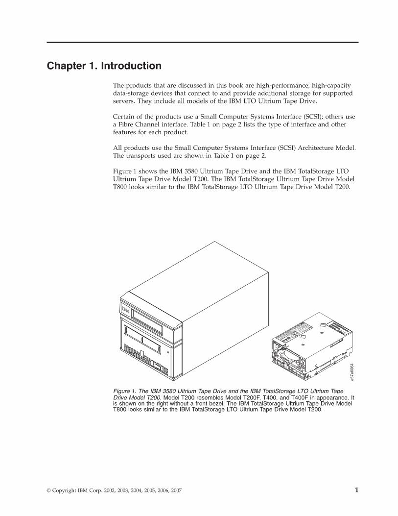
Figure 1 shows the IBM 3580 Ultrium Tape Drive and the IBM TotalStorage LTO
Ultrium Tape Drive Model T200. The IBM TotalStorage Ultrium Tape Drive Model
T800 looks similar to the IBM TotalStorage LTO Ultrium Tape Drive Model T200.
Figure 1. The IBM 3580 Ultrium Tape Drive and the IBM TotalStorage LTO Ultrium Tape
Drive Model T200. Model T200 resembles Model T200F, T400, and T400F in appearance. It
is shown on the right without a front bezel. The IBM TotalStorage Ultrium Tape Drive Model
T800 looks similar to the IBM TotalStorage LTO Ultrium Tape Drive Model T200.
© Copyright IBM Corp. 2002, 2003, 2004, 2005, 2006, 2007 1
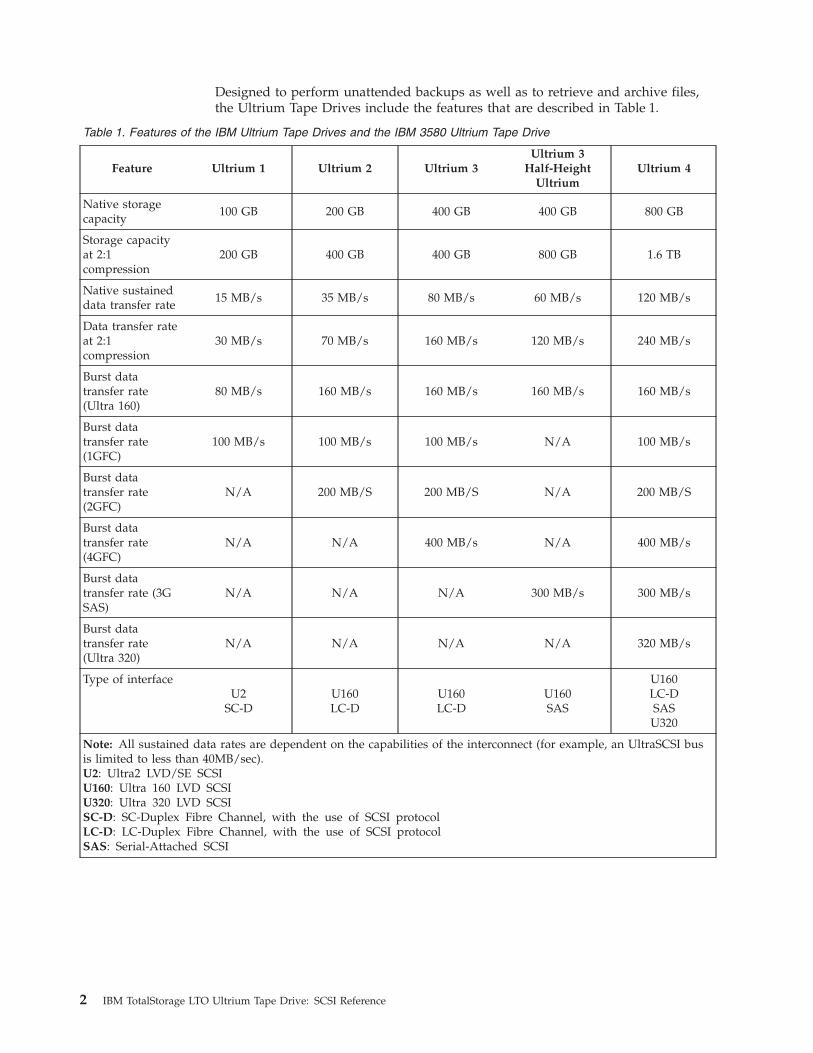
Designed to perform unattended backups as well as to retrieve and archive files,
the Ultrium Tape Drives include the features that are described in Table 1.
Table 1. Features of the IBM Ultrium Tape Drives and the IBM 3580 Ultrium Tape Drive
Feature Ultrium 1 Ultrium 2 Ultrium 3
Ultrium 3
Half-Height
Ultrium
Ultrium 4
Native storage
capacity
100 GB 200 GB 400 GB 400 GB 800 GB
Storage capacity
at 2:1
compression
200 GB 400 GB 400 GB 800 GB 1.6 TB
Native sustained
data transfer rate
15 MB/s 35 MB/s 80 MB/s 60 MB/s 120 MB/s
Data transfer rate
at 2:1
compression
30 MB/s 70 MB/s 160 MB/s 120 MB/s 240 MB/s
Burst data
transfer rate
(Ultra 160)
80 MB/s 160 MB/s 160 MB/s 160 MB/s 160 MB/s
Burst data
transfer rate
(1GFC)
100 MB/s 100 MB/s 100 MB/s N/A 100 MB/s
Burst data
transfer rate
(2GFC)
N/A 200 MB/S 200 MB/S N/A 200 MB/S
Burst data
transfer rate
(4GFC)
N/A N/A 400 MB/s N/A 400 MB/s
Burst data
transfer rate (3G
SAS)
N/A N/A N/A 300 MB/s 300 MB/s
Burst data
transfer rate
(Ultra 320)
N/A N/A N/A N/A 320 MB/s
Type of interface
U2SC-D
U160LC-D
U160LC-D
U160SAS
U160LC-DSASU320
Note: All sustained data rates are dependent on the capabilities of the interconnect (for example, an UltraSCSI bus
is limited to less than 40MB/sec).U2: Ultra2 LVD/SE SCSI
U160: Ultra 160 LVD SCSI
U320: Ultra 320 LVD SCSI
SC-D: SC-Duplex Fibre Channel, with the use of SCSI protocol
LC-D: LC-Duplex Fibre Channel, with the use of SCSI protocol
SAS: Serial-Attached SCSI
2 IBM TotalStorage LTO Ultrium Tape Drive: SCSI Reference
Supported Servers and Operating Systems
The Ultrium Tape Drives are supported by a wide variety of servers and operating
systems, as well as adapters. These attachments can change throughout the
products’ life cycles. To determine the latest supported attachments, visit the web
at http://www.ibm.com/storage/lto and click on Technical Support or LTO
Support.
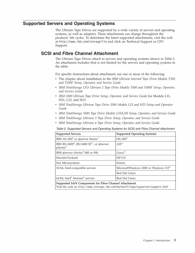
SCSI and Fibre Channel Attachment
The Ultrium Tape Drives attach to servers and operating systems shown in Table 2.
An attachment includes (but is not limited to) the servers and operating systems in
the table.
For specific instructions about attachment, see one or more of the following:
v The chapter about installation in the IBM Ultrium Internal Tape Drive Models T200
and T200F Setup, Operator, and Service Guide
v IBM TotalStorage LTO Ultrium 2 Tape Drive Models T400 and T400F Setup, Operator,
and Service Guide
v IBM 3580 Ultrium Tape Drive Setup, Operator, and Service Guide for Models L11,
H11, L13, and H13
v IBM TotalStorage Ultrium Tape Drive 3580 Models L23 and H23 Setup and Operator
Guide
v IBM TotalStorage 3580 Tape Drive Models L33/L3H Setup, Operator, and Service Guide
v IBM TotalStorage Ultrium 3 Tape Drive Setup, Operator, and Service Guide
v IBM TotalStorage Ultrium 4 Tape Drive Setup, Operator, and Service Guide
Table 2. Supported Servers and Operating Systems for SCSI and Fibre Channel Attachment
Supported Servers Supported Operating Systems
IBM AS/400® or ERserver iSeries™ OS/400®
IBM RS/6000®, RS/6000 SP™, or Eserver
pSeries®
AIX®
IBM Eserver zSeries® 800 or 900 Linux®
Hewlett-Packard HP-UX
Sun Microsystems Solaris
32-bit, Intel-compatible servers MicrosoftWindows 2000 or Windows NT®
Red Hat Linux
64-bit, Intel® Itanium® servers Red Hat Linux
Supported SAN Components for Fibre Channel AttachmentVisit the web at: http://www.storage.ibm.com/hardsoft/tape/supserver/support.html
Chapter 1. Introduction 3
Supported Device Drivers
IBM maintains the latest levels of device drivers and driver documentation for the
IBM Ultrium Tape Drives on the Internet. You can access this material from your
browser or through the IBM FTP site by performing one of the following
procedures. (Note: If you do not have Internet access and you need information
about device drivers, contact your Marketing Representative.)
v Using a browser, type one of the following:
– http://www.ibm.com/storage
– ftp://ftp.software.ibm.com/storage/devdrvr
– ftp://207.25.253.26/storage/devdrvr
v Using an IBM FTP site, enter the following specifications:
– FTP site: ftp.software.ibm.com
– IP Addr: 207.25.253.26
– Userid: anonymous
– Password: (use your current e-mail address)
– Directory: /storage/devdrvr
IBM provides PostScript- and PDF-formatted versions of its documentation in the
/storage/devdrvr/doc directory:
v IBM_ultrium_tape_IUG.ps and IBM_ultrium_tape_IUG.pdf contain the current
version of the IBM Ultrium Device Drivers Installation and User’s Guide
v IBM_ultrium_tape_PROGREF.ps and IBM_ultrium_tape_PROGREF.pdf contain
the current version of the IBM Ultrium Device Drivers Programming Reference
Device drivers and utilities for each supported server are beneath
/storage/devdrvr/ in the following directories (the device driver for the iSeries or
AS/400 server is included in the OS/400 operating system):
v AIX
v HPUX
v Linux
v Solaris
v Tru64
v WinNT
v Win2000
For more information about device drivers, refer to any of the preceding
directories.
4 IBM TotalStorage LTO Ultrium Tape Drive: SCSI Reference
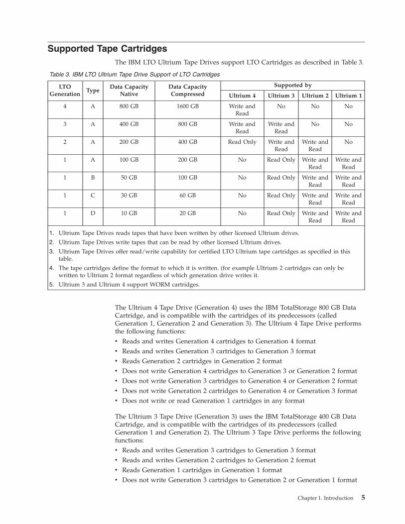
Supported Tape Cartridges
The IBM LTO Ultrium Tape Drives support LTO Cartridges as described in Table 3.
Table 3. IBM LTO Ultrium Tape Drive Support of LTO Cartridges
LTOGeneration
Type
Data CapacityNative
Data CapacityCompressed
Supported by
Ultrium 4 Ultrium 3 Ultrium 2 Ultrium 1
4 A 800 GB 1600 GB Write and
Read
No No No
3 A 400 GB 800 GB Write and
Read
Write and
Read
No No
2 A 200 GB 400 GB Read Only Write and
Read
Write and
Read
No
1 A 100 GB 200 GB No Read Only Write and
Read
Write and
Read
1 B 50 GB 100 GB No Read Only Write and
Read
Write and
Read
1 C 30 GB 60 GB No Read Only Write and
Read
Write and
Read
1 D 10 GB 20 GB No Read Only Write and
Read
Write and
Read
1. Ultrium Tape Drives reads tapes that have been written by other licensed Ultrium drives.
2. Ultrium Tape Drives write tapes that can be read by other licensed Ultrium drives.
3. Ultrium Tape Drives offer read/write capability for certified LTO Ultrium tape cartridges as specified in this
table.
4. The tape cartridges define the format to which it is written. (for example Ultrium 2 cartridges can only be
written to Ultrium 2 format regardless of which generation drive writes it.
5. Ultrium 3 and Ultrium 4 support WORM cartridges.
The Ultrium 4 Tape Drive (Generation 4) uses the IBM TotalStorage 800 GB Data
Cartridge, and is compatible with the cartridges of its predecessors (called
Generation 1, Generation 2 and Generation 3). The Ultrium 4 Tape Drive performs
the following functions:
v Reads and writes Generation 4 cartridges to Generation 4 format
v Reads and writes Generation 3 cartridges to Generation 3 format
v Reads Generation 2 cartridges in Generation 2 format
v Does not write Generation 4 cartridges to Generation 3 or Generation 2 format
v Does not write Generation 3 cartridges to Generation 4 or Generation 2 format
v Does not write Generation 2 cartridges to Generation 4 or Generation 3 format
v Does not write or read Generation 1 cartridges in any format
The Ultrium 3 Tape Drive (Generation 3) uses the IBM TotalStorage 400 GB Data
Cartridge, and is compatible with the cartridges of its predecessors (called
Generation 1 and Generation 2). The Ultrium 3 Tape Drive performs the following
functions:
v Reads and writes Generation 3 cartridges to Generation 3 format
v Reads and writes Generation 2 cartridges to Generation 2 format
v Reads Generation 1 cartridges in Generation 1 format
v Does not write Generation 3 cartridges to Generation 2 or Generation 1 format
Chapter 1. Introduction 5
v Does not write Generation 2 cartridges to Generation 3 or Generation 1 format
v Does not write Generation 1 cartridges to Generation 3 or Generation 2 format
The Ultrium 3 Tape Drive reads tapes that have been written by other licensed
Ultrium 3 drives. It also writes tapes that can be read by other licensed Ultrium 3
drives.
Ultrium 3 Tape Drives offer read/write capability for certified LTO Ultrium tape
cartridges that have capacities of 400 and 200 GB. They also offer read capability
for certified LTO Ultrium tape cartridges that have a capacity of 100 GB.
The Ultrium 2 Tape Drive (Generation 2) uses the IBM TotalStorage LTO Ultrium
200 GB Data Cartridge and is compatible with the cartridges of its predecessor, the
IBM Ultrium Internal Tape Drive (called Generation 1). The Ultrium 2 Tape Drive
performs the following functions:
v Reads and writes Generation 2 cartridges to Generation 2 format
v Reads and writes Generation 1 cartridges to Generation 1 format
v Does not write Generation 2 cartridges to Generation 1 format
v Does not write Generation 1 cartridges to Generation 2 format
The Ultrium 2 Tape Drive reads tapes that have been written by other licensed
Ultrium 2 drives. It also writes to tapes that can be read by other licensed Ultrium
2 drives.
Ultrium 2 Tape Drives offer read/write capability for certified LTO Ultrium tape
cartridges that have capacities of 200 and 100 GB.
Ultrium 1 Tape Drives offer read/write capability for certified LTO Ultrium tape
cartridges that have a capacity of 100 GB.
6 IBM TotalStorage LTO Ultrium Tape Drive: SCSI Reference
Chapter 2. Summary of Drive Generation Differences
This chapter provides a summary of the differences in host attachment protocol
between the Ultrium Internal Tape Drive (Generation 1), the TotalStorage LTO
Ultrium 2 Tape Drive (Generation 2), and the TotalStorage Ultrium 3 Tape Drive
(Generation 3), the TotalStorage Ultrium 3 Half-High Tape Drive (Generation
3HH), and the TotalStorage Ultrium 4 Tape Drive (Generation 4).
The features of the Generation 2 drive that differ from the Generation 1 drive
include:
v 64-MB read-and-write cache
v Speed matching
v Channel calibration
v SET CAPACITY SCSI command
v Ultra160 SCSI interface
v Drive external SCSI termination required
v Fibre Channel 2-Gb/s interface
v Fibre Channel support for direct connection to an F port (for example, a McData
switch)
v Parallel SCSI Ultra 320 interface
The features of the Ultrium 3 Tape Drive that differ from those of the Ultrium 2
Tape Drive include the following:
v 128 MB read-and-write cache
v New media, new media shell color (dark bluish gray, Pantone color number
7546C)
v Expanded request sense length to 96 bytes
The features of the Ultrium 4 Tape Drive that differ from those of the Ultrium 3
HH, Ultrium 3, and Ultrium 2 Tape Drive include the following:
v Half-Height drive option with:
1. Serial Attached SCSI (SAS) Interface, or
2. Ultra160 SCSI interfacev 128 MB read-and-write cache
v Encryption of data on Ultrium 4 cartridges
1. T 10 key management method
2. Transparent management method
a. when using IBM device driver, or
b. when in a 3584v New log pages
1. Device Statistics log page (14h)
2. Tape Diagnostic data log page (16h)
3. Performance Characteristics log page (37h)v Fibre Channel 4Gbit/sec interface
v Serial Attached SCSI (SAS) interface
© Copyright IBM Corp. 2002, 2003, 2004, 2005, 2006, 2007 7
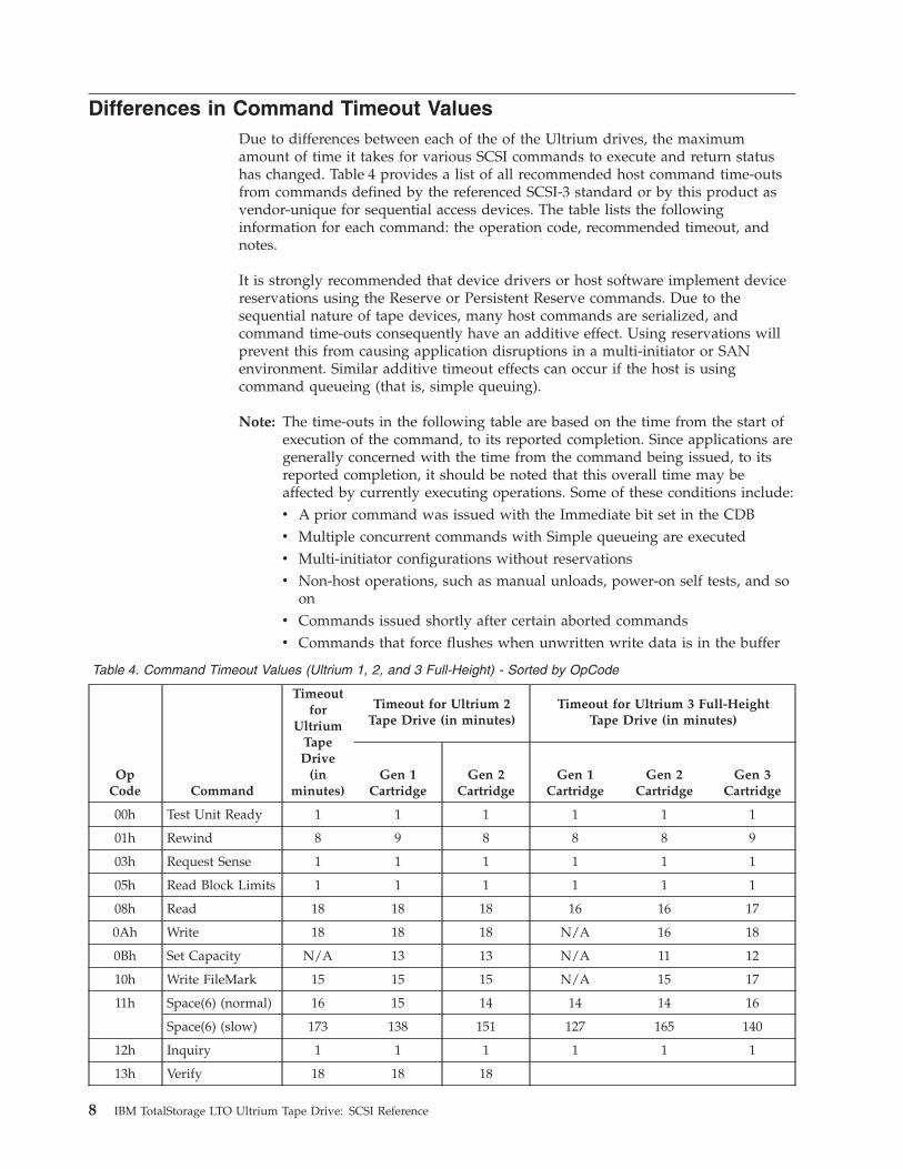
Differences in Command Timeout Values
Due to differences between each of the of the Ultrium drives, the maximum
amount of time it takes for various SCSI commands to execute and return status
has changed. Table 4 provides a list of all recommended host command time-outs
from commands defined by the referenced SCSI-3 standard or by this product as
vendor-unique for sequential access devices. The table lists the following
information for each command: the operation code, recommended timeout, and
notes.
It is strongly recommended that device drivers or host software implement device
reservations using the Reserve or Persistent Reserve commands. Due to the
sequential nature of tape devices, many host commands are serialized, and
command time-outs consequently have an additive effect. Using reservations will
prevent this from causing application disruptions in a multi-initiator or SAN
environment. Similar additive timeout effects can occur if the host is using
command queueing (that is, simple queuing).
Note: The time-outs in the following table are based on the time from the start of
execution of the command, to its reported completion. Since applications are
generally concerned with the time from the command being issued, to its
reported completion, it should be noted that this overall time may be
affected by currently executing operations. Some of these conditions include:
v A prior command was issued with the Immediate bit set in the CDB
v Multiple concurrent commands with Simple queueing are executed
v Multi-initiator configurations without reservations
v Non-host operations, such as manual unloads, power-on self tests, and so
on
v Commands issued shortly after certain aborted commands
v Commands that force flushes when unwritten write data is in the buffer
Table 4. Command Timeout Values (Ultrium 1, 2, and 3 Full-Height) - Sorted by OpCode
OpCode Command
Timeoutfor
Ultrium
Tape
Drive(in
minutes)
Timeout for Ultrium 2Tape Drive (in minutes)
Timeout for Ultrium 3 Full-HeightTape Drive (in minutes)
Gen 1
Cartridge
Gen 2
Cartridge
Gen 1
Cartridge
Gen 2
Cartridge
Gen 3
Cartridge
00h Test Unit Ready 1 1 1 1 1 1
01h Rewind 8 9 8 8 8 9
03h Request Sense 1 1 1 1 1 1
05h Read Block Limits 1 1 1 1 1 1
08h Read 18 18 18 16 16 17
0Ah Write 18 18 18 N/A 16 18
0Bh Set Capacity N/A 13 13 N/A 11 12
10h Write FileMark 15 15 15 N/A 15 17
11h Space(6) (normal) 16 15 14 14 14 16
Space(6) (slow) 173 138 151 127 165 140
12h Inquiry 1 1 1 1 1 1
13h Verify 18 18 18
8 IBM TotalStorage LTO Ultrium Tape Drive: SCSI Reference
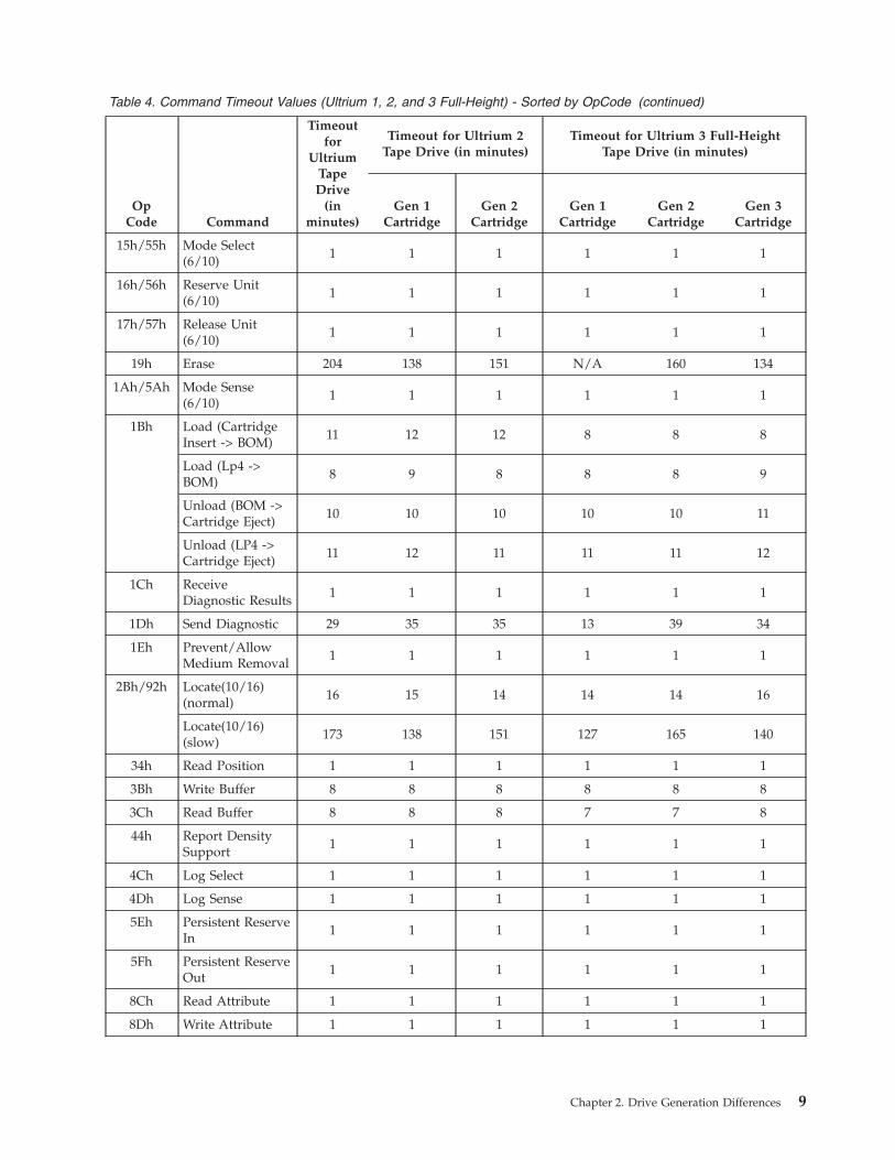
Table 4. Command Timeout Values (Ultrium 1, 2, and 3 Full-Height) - Sorted by OpCode (continued)
OpCode Command
Timeoutfor
Ultrium
Tape
Drive(in
minutes)
Timeout for Ultrium 2Tape Drive (in minutes)
Timeout for Ultrium 3 Full-HeightTape Drive (in minutes)
Gen 1
Cartridge
Gen 2
Cartridge
Gen 1
Cartridge
Gen 2
Cartridge
Gen 3
Cartridge
15h/55h Mode Select
(6/10)
1 1 1 1 1 1
16h/56h Reserve Unit
(6/10)
1 1 1 1 1 1
17h/57h Release Unit
(6/10)
1 1 1 1 1 1
19h Erase 204 138 151 N/A 160 134
1Ah/5Ah Mode Sense
(6/10)
1 1 1 1 1 1
1Bh Load (Cartridge
Insert -> BOM)
11 12 12 8 8 8
Load (Lp4 ->
BOM)
8 9 8 8 8 9
Unload (BOM ->
Cartridge Eject)
10 10 10 10 10 11
Unload (LP4 ->
Cartridge Eject)
11 12 11 11 11 12
1Ch Receive
Diagnostic Results
1 1 1 1 1 1
1Dh Send Diagnostic 29 35 35 13 39 34
1Eh Prevent/Allow
Medium Removal
1 1 1 1 1 1
2Bh/92h Locate(10/16)
(normal)
16 15 14 14 14 16
Locate(10/16)
(slow)
173 138 151 127 165 140
34h Read Position 1 1 1 1 1 1
3Bh Write Buffer 8 8 8 8 8 8
3Ch Read Buffer 8 8 8 7 7 8
44h Report Density
Support
1 1 1 1 1 1
4Ch Log Select 1 1 1 1 1 1
4Dh Log Sense 1 1 1 1 1 1
5Eh Persistent Reserve
In
1 1 1 1 1 1
5Fh Persistent Reserve
Out
1 1 1 1 1 1
8Ch Read Attribute 1 1 1 1 1 1
8Dh Write Attribute 1 1 1 1 1 1
Chapter 2. Drive Generation Differences 9
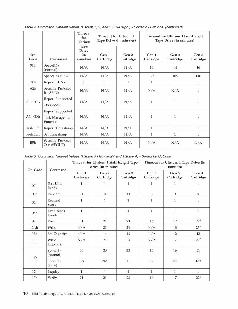
Table 4. Command Timeout Values (Ultrium 1, 2, and 3 Full-Height) - Sorted by OpCode (continued)
OpCode Command
Timeoutfor
Ultrium
Tape
Drive(in
minutes)
Timeout for Ultrium 2Tape Drive (in minutes)
Timeout for Ultrium 3 Full-HeightTape Drive (in minutes)
Gen 1
Cartridge
Gen 2
Cartridge
Gen 1
Cartridge
Gen 2
Cartridge
Gen 3
Cartridge
91h Space(16)
(normal)
N/A N/A N/A 14 14 16
Space(16) (slow) N/A N/A N/A 127 165 140
A0h Report LUNs 1 1 1 1 1 1
A2h Security Protocol
In (SPIN)
N/A N/A N/A N/A N/A 1
A3h:0Ch
Report Supported
N/A N/A N/A 1 1 1
Op Codes
A3h:0Dh
Report Supported
N/A N/A N/A 1 1 1 Task Management
Functions
A3h:0Fh Report Timestamp N/A N/A N/A 1 1 1
A4h:0Fh Set Timestamp N/A N/A N/A 1 1 1
B5h
Security Protocol
Out (SPOUT)
N/A N/A N/A N/A N/A N/A
Table 5. Command Timeout Values (Ultrium 3 Half-Height and Ultrium 4) - Sorted by OpCode
Op Code Command
Timeout for Ultrium 3 Half-Height Tape
drive (in minutes)
Timeout for Ultrium 4 Tape Drive (in
minutes)
Gen 1
Cartridge
Gen 2
Cartridge
Gen 3
Cartridge
Gen 2
Cartridge
Gen 3
Cartridge
Gen 4
Cartridge
00h
Test Unit
Ready
1 1 1 1 1 1
01h Rewind 11 11 13 8 9 9
03h
Request
Sense
1 1 1 1 1 1
05h
Read Block
Limits
1 1 1 1 1 1
08h Read 21 21 23 16 17 224
0Ah Write N/A 21 24 N/A 18 235
0Bh Set Capacity N/A 14 16 N/A 12 12
10h
Write
FileMark
N/A 21 23 N/A 17 227
11h
Space(6)
(normal)
20 20 22 14 16 21
Space(6)
(slow)
199 264 201 165 140 183
12h Inquiry 1 1 1 1 1 1
13h Verify 21 21 23 16 17 224
10 IBM TotalStorage LTO Ultrium Tape Drive: SCSI Reference
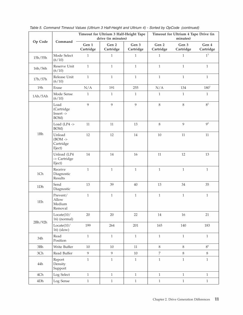
Table 5. Command Timeout Values (Ultrium 3 Half-Height and Ultrium 4) - Sorted by OpCode (continued)
Op Code Command
Timeout for Ultrium 3 Half-Height Tape
drive (in minutes)
Timeout for Ultrium 4 Tape Drive (in
minutes)
Gen 1
Cartridge
Gen 2
Cartridge
Gen 3
Cartridge
Gen 2
Cartridge
Gen 3
Cartridge
Gen 4
Cartridge
15h/55h
Mode Select
(6/10)
1 1 1 1 1 13
16h/56h
Reserve Unit
(6/10)
1 1 1 1 1 1
17h/57h
Release Unit
(6/10)
1 1 1 1 1 1
19h Erase N/A 191 255 N/A 134 1801
1Ah/5Ah
Mode Sense
(6/10)
1 1 1 1 1 1
1Bh
Load
(Cartridge
Insert ->
BOM)
9 9 9 8 8 82
Load (LP4 ->
BOM)
11 11 13 8 9 92
Unload
(BOM ->
Cartridge
Eject)
12 12 14 10 11 11
Unload (LP4
-> Cartridge
Eject)
14 14 16 11 12 13
1Ch
Receive
Diagnostic
Results
1 1 1 1 1 1
1Dh
Send
Diagnostic
13 39 40 13 34 35
1Eh
Prevent/Allow
Medium
Removal
1 1 1 1 1 1
2Bh/92h
Locate(10/16) (normal)
20 20 22 14 16 21
Locate(10/16) (slow)
199 264 201 165 140 183
34h
Read
Position
1 1 1 1 1 1
3Bh Write Buffer 10 10 11 8 8 86
3Ch Read Buffer 9 9 10 7 8 8
44h
Report
Density
Support
1 1 1 1 1 1
4Ch Log Select 1 1 1 1 1 1
4Dh Log Sense 1 1 1 1 1 1
Chapter 2. Drive Generation Differences 11
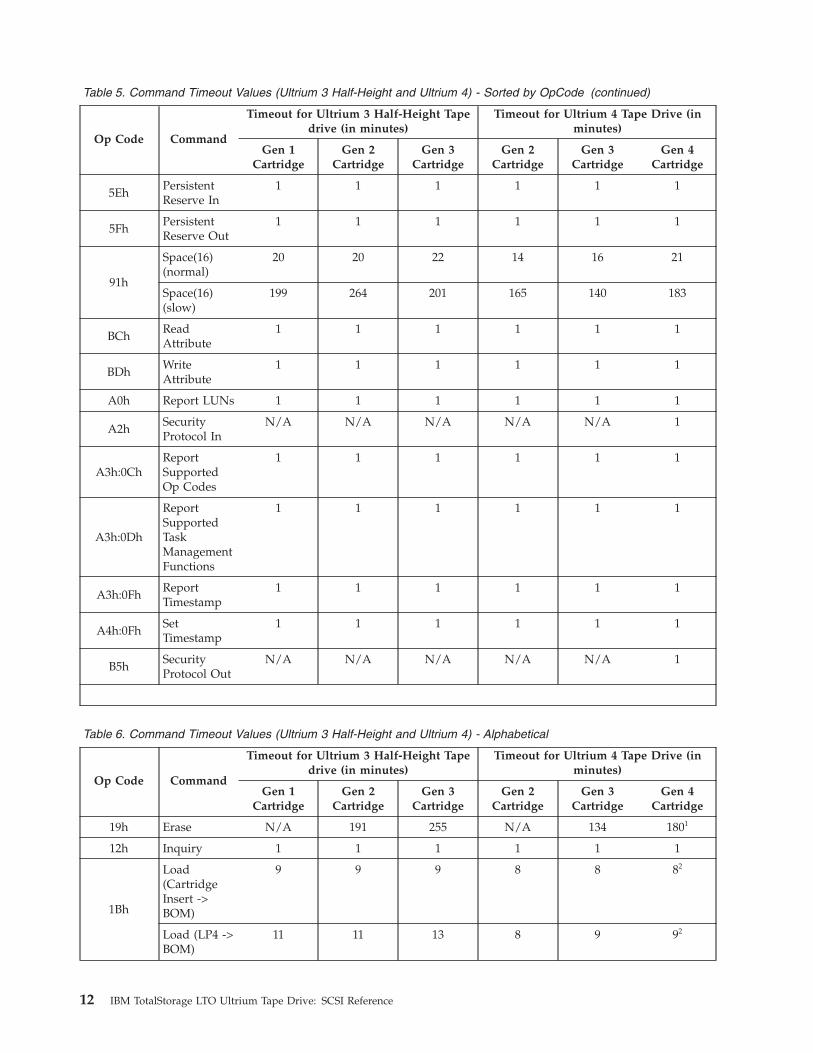
Table 5. Command Timeout Values (Ultrium 3 Half-Height and Ultrium 4) - Sorted by OpCode (continued)
Op Code Command
Timeout for Ultrium 3 Half-Height Tape
drive (in minutes)
Timeout for Ultrium 4 Tape Drive (in
minutes)
Gen 1
Cartridge
Gen 2
Cartridge
Gen 3
Cartridge
Gen 2
Cartridge
Gen 3
Cartridge
Gen 4
Cartridge
5Eh
Persistent
Reserve In
1 1 1 1 1 1
5Fh
Persistent
Reserve Out
1 1 1 1 1 1
91h
Space(16)
(normal)
20 20 22 14 16 21
Space(16)
(slow)
199 264 201 165 140 183
BCh
Read
Attribute
1 1 1 1 1 1
BDh
Write
Attribute
1 1 1 1 1 1
A0h Report LUNs 1 1 1 1 1 1
A2h
Security
Protocol In
N/A N/A N/A N/A N/A 1
A3h:0Ch
Report
Supported
Op Codes
1 1 1 1 1 1
A3h:0Dh
Report
Supported
Task
Management
Functions
1 1 1 1 1 1
A3h:0Fh
Report
Timestamp
1 1 1 1 1 1
A4h:0Fh
Set
Timestamp
1 1 1 1 1 1
B5h
Security
Protocol Out
N/A N/A N/A N/A N/A 1
Table 6. Command Timeout Values (Ultrium 3 Half-Height and Ultrium 4) - Alphabetical
Op Code Command
Timeout for Ultrium 3 Half-Height Tape
drive (in minutes)
Timeout for Ultrium 4 Tape Drive (in
minutes)
Gen 1
Cartridge
Gen 2
Cartridge
Gen 3
Cartridge
Gen 2
Cartridge
Gen 3
Cartridge
Gen 4
Cartridge
19h Erase N/A 191 255 N/A 134 1801
12h Inquiry 1 1 1 1 1 1
1Bh
Load
(Cartridge
Insert ->
BOM)
9 9 9 8 8 82
Load (LP4 ->
BOM)
11 11 13 8 9 92
12 IBM TotalStorage LTO Ultrium Tape Drive: SCSI Reference

Table 6. Command Timeout Values (Ultrium 3 Half-Height and Ultrium 4) - Alphabetical (continued)
Op Code Command
Timeout for Ultrium 3 Half-Height Tape
drive (in minutes)
Timeout for Ultrium 4 Tape Drive (in
minutes)
Gen 1
Cartridge
Gen 2
Cartridge
Gen 3
Cartridge
Gen 2
Cartridge
Gen 3
Cartridge
Gen 4
Cartridge
2Bh/92h
Locate(10/16) (normal)
20 20 22 14 16 21
Locate(10/16) (slow)
199 264 201 165 140 183
4Ch Log Select 1 1 1 1 1 1
4Dh Log Sense 1 1 1 1 1 1
15h/55h
Mode Select
(6/10)
1 1 1 1 1 13
1Ah/5Ah
Mode Sense
(6/10)
1 1 1 1 1 1
5Eh
Persistent
Reserve In
1 1 1 1 1 1
5Fh
Persistent
Reserve Out
1 1 1 1 1 1
1Eh
Prevent/Allow
Medium
Removal
1 1 1 1 1 1
08h Read 21 21 23 16 17 224
BCh
Read
Attribute
1 1 1 1 1 1
05h
Read Block
Limits
1 1 1 1 1 1
3Ch Read Buffer 9 9 10 7 8 8
34h
Read
Position
1 1 1 1 1 1
1Ch
Receive
Diagnostic
Results
1 1 1 1 1 1
17h/57h
Release Unit
(6/10)
1 1 1 1 1 1
44h
Report
Density
Support
1 1 1 1 1 1
A0h Report LUNs 1 1 1 1 1 1
A3h:0Ch
Report
Supported
Op Codes
1 1 1 1 1 1
A3h:0Dh
Report
Supported
Task
Management
Functions
1 1 1 1 1 1
A3h:0Fh
Report
Timestamp
1 1 1 1 1 1
Chapter 2. Drive Generation Differences 13
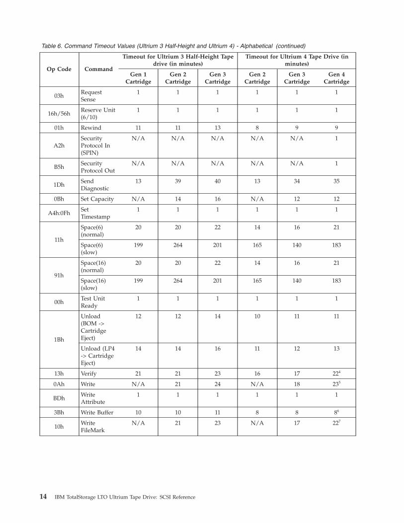
Table 6. Command Timeout Values (Ultrium 3 Half-Height and Ultrium 4) - Alphabetical (continued)
Op Code Command
Timeout for Ultrium 3 Half-Height Tape
drive (in minutes)
Timeout for Ultrium 4 Tape Drive (in
minutes)
Gen 1
Cartridge
Gen 2
Cartridge
Gen 3
Cartridge
Gen 2
Cartridge
Gen 3
Cartridge
Gen 4
Cartridge
03h
Request
Sense
1 1 1 1 1 1
16h/56h
Reserve Unit
(6/10)
1 1 1 1 1 1
01h Rewind 11 11 13 8 9 9
A2h
Security
Protocol In
(SPIN)
N/A N/A N/A N/A N/A 1
B5h
Security
Protocol Out
N/A N/A N/A N/A N/A 1
1Dh
Send
Diagnostic
13 39 40 13 34 35
0Bh Set Capacity N/A 14 16 N/A 12 12
A4h:0Fh
Set
Timestamp
1 1 1 1 1 1
11h
Space(6)
(normal)
20 20 22 14 16 21
Space(6)
(slow)
199 264 201 165 140 183
91h
Space(16)
(normal)
20 20 22 14 16 21
Space(16)
(slow)
199 264 201 165 140 183
00h
Test Unit
Ready
1 1 1 1 1 1
1Bh
Unload
(BOM ->
Cartridge
Eject)
12 12 14 10 11 11
Unload (LP4
-> Cartridge
Eject)
14 14 16 11 12 13
13h Verify 21 21 23 16 17 224
0Ah Write N/A 21 24 N/A 18 235
BDh
Write
Attribute
1 1 1 1 1 1
3Bh Write Buffer 10 10 11 8 8 86
10h
Write
FileMark
N/A 21 23 N/A 17 227
14 IBM TotalStorage LTO Ultrium Tape Drive: SCSI Reference

Command and Parameter differences between generations
Table 7 shows commands and parameters added since Ultrium 1 and in which
generation(s) it is applicable.
Table 7. Command and Parameter differences between generations
Command or
Parameter
Description
Generation
2 3 4
Set Capacity
Command
The SET CAPACITY command is supported. The minimum capacity
allowed varies from one generation to another. For more information, see
“SET CAPACITY (not Ultrium 1)” on page 234.
Y Y Y
Echo Buffer Support Echo Buffer mode of the READ BUFFER and WRITE BUFFER
commands (see “READ BUFFER” on page 166 and “WRITE BUFFER” on
page 242, respectively).
Y Y Y
Volume Identifier Volume Identifier Part of the Device Attribute of Medium Auxiliary
Memory. This is the volume identifier (VolSer or BarCode) value set by
the library
- - Y
Security Protocol In
(SPIN)
This command is related to managing encryption. See “SECURITY
PROTOCOL IN (SPIN) A2h” on page 194.
- - Y
Security Protocol Out
(SPOUT)
This command is related to managing encryption. See “SECURITY
PROTOCOL OUT (SPOUT) B5h” on page 203.
- - Y
Key:
- Not Supported
Data Changes Between Generations
The sections that follow describe the data changes between Generations of the
Ultrium tape drive.
Standard Inquiry Data
The length of Standard Inquiry data on Ultrium 1 drives is less than on later
generations. The Standard Inquiry data reported by Ultrium drives is shown in
Table 11 on page 22. The Additional Length field specifies how many bytes are
returned. Currently, Ultrium 1 devices set this value to 33 (21h) and later
generation devices set this value to 53 (35h). This value is subject to change. It is
strongly recommended that the user parse the data returned by using the
Additional Length field instead of the published values.
Product Identification information returned is shown in Table 12 on page 24..
For more information, see “Standard Inquiry Data” on page 22.
REPORT DENSITY SUPPORT Command
The REPORT DENSITY SUPPORT command has added density values for all
generations through Ultrium 4. Additionally, the units in which the Capacity value
are returned has changed to match the SCSI standards. See Table 180 on page 180.
For more information, see “REPORT DENSITY SUPPORT” on page 178.
Chapter 2. Drive Generation Differences 15
%
Mode Pages
On Mode Sense commands the value returned in the Medium Type field is shown
in Table 97 on page 107. On Mode Select commands any value is allowed and
ignored.
Fibre Channel Port Control Page (19h) Page Length changed from 0Eh in Ultrium 1
drives to 06h in later generation 2 drives. This matches the definition in the SCSI
standards (FCP-2 and later). For more information, see “Mode Page 19h: Protocol
Specific Port Control Page” on page 120.
READ POSITION Command
The READ POSITION command for all generation drives except Ultrium 1 behaves
as described in the SCSI standards (SPC-2). For more information, see “READ
POSITION” on page 173.
Request Sense Changes
For Request Sense data, the Additional Sense Length is set to n-7, and is at least
10. When the sense data is associated with an Illegal Length read, the Additional
Sense Length may be 10. In Ultrium 1 and Ultrium 2 drives, n can be as large as
35. In Ultrium 3 and later generation drives, n can be as large as 95. While this
length is not anticipated to change, it is recommended that the Additional Sense
Length be used to parse the data. For more information, see “REQUEST SENSE”
on page 187.
Behavior Changes Between Generations
Cartridge Eject for Errors
Ultrium 1 drives auto-eject data cartridges when errors occur during loads. Later
generation drives do not.
Queueing Issues
For all generations of drive later than Ultrium 1, when a cartridge is inserted into
the drive through means other than SCSI commands to LUN 0, it is assumed that
the host will poll the drive with TEST UNIT READY commands to determine its
readiness before issuing in-order commands (for example, commands other than
INQUIRY, TEST UNIT READY, REQUEST SENSE, or REPORT LUNS). If this is not
the case, these commands may time out in ERP (Error Recovery Procedure)
situations.
Microcode Detection of Errors
The drive microcode is designed to check for logic errors, to handle
hardware-detected errors, and to detect and report microcode-related errors.
Fencing Behavior
For a description of the Fencing Behavior and Persistent Error handling, see
“Persistent Errors” on page 246.
16 IBM TotalStorage LTO Ultrium Tape Drive: SCSI Reference
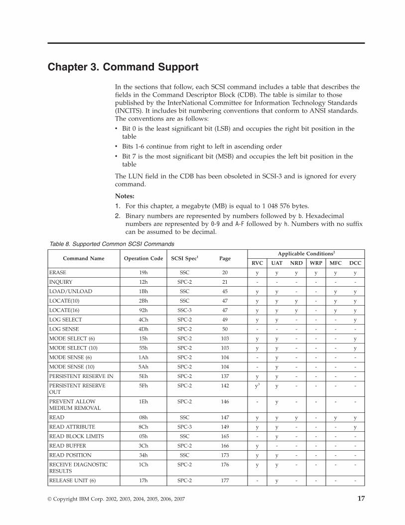
Chapter 3. Command Support
In the sections that follow, each SCSI command includes a table that describes the
fields in the Command Descriptor Block (CDB). The table is similar to those
published by the InterNational Committee for Information Technology Standards
(INCITS). It includes bit numbering conventions that conform to ANSI standards.
The conventions are as follows:
v Bit 0 is the least significant bit (LSB) and occupies the right bit position in the
table
v Bits 1-6 continue from right to left in ascending order
v Bit 7 is the most significant bit (MSB) and occupies the left bit position in the
table
The LUN field in the CDB has been obsoleted in SCSI-3 and is ignored for every
command.
Notes:
1. For this chapter, a megabyte (MB) is equal to 1 048 576 bytes.
2. Binary numbers are represented by numbers followed by b. Hexadecimal
numbers are represented by 0-9 and A-F followed by h. Numbers with no suffix
can be assumed to be decimal.
Table 8. Supported Common SCSI Commands
Command Name Operation Code SCSI Spec1 Page
Applicable Conditions2
RVC UAT NRD WRP MFC DCC
ERASE 19h SSC 20 y y y y y y
INQUIRY 12h SPC-2 21 - - - - - -
LOAD/UNLOAD 1Bh SSC 45 y y - - y y
LOCATE(10) 2Bh SSC 47 y y y - y y
LOCATE(16) 92h SSC-3 47 y y y - y y
LOG SELECT 4Ch SPC-2 49 y y - - - y
LOG SENSE 4Dh SPC-2 50 - - - - - -
MODE SELECT (6) 15h SPC-2 103 y y - - - y
MODE SELECT (10) 55h SPC-2 103 y y - - - y
MODE SENSE (6) 1Ah SPC-2 104 - y - - - -
MODE SENSE (10) 5Ah SPC-2 104 - y - - - -
PERSISTENT RESERVE IN 5Eh SPC-2 137 y y - - - -
PERSISTENT RESERVE
OUT
5Fh SPC-2 142 y3 y - - - -
PREVENT ALLOW
MEDIUM REMOVAL
1Eh SPC-2 146 - y - - - -
READ 08h SSC 147 y y y - y y
READ ATTRIBUTE 8Ch SPC-3 149 y y - - - y
READ BLOCK LIMITS 05h SSC 165 - y - - - -
READ BUFFER 3Ch SPC-2 166 y - - - - -
READ POSITION 34h SSC 173 y y - - - -
RECEIVE DIAGNOSTIC
RESULTS
1Ch SPC-2 176 y y - - - -
RELEASE UNIT (6) 17h SPC-2 177 - y - - - -
© Copyright IBM Corp. 2002, 2003, 2004, 2005, 2006, 2007 17

Table 8. Supported Common SCSI Commands (continued)
Command Name Operation Code SCSI Spec1 Page
Applicable Conditions2
RVC UAT NRD WRP MFC DCC
RELEASE UNIT (10) 57h SPC-2 177 - y - - - -
REPORT DENSITY
SUPPORT
44h SSC 178 - y - - - -
REPORT LUNs A0h SSC 183 - - - - - -
REPORT SUPPORTED
TASK MANAGEMENT
FUNCTIONS
A3h/0Dh SPC-4 “REPORT
SUPPORTED
TASK
MANAGEMENT
FUNCTIONS
(Not LTO1)” on
page 185
- - - - - -
REQUEST SENSE 03h SPC-2 187 - - - - - -
RESERVE UNIT (6) 16h SPC-2 192 y y - - - -
RESERVE UNIT (10) 56h SPC-2 192 y y - - - -
REWIND 01h SSC 193 y y y - y y
SECURITY PROTOCOL IN
(SPIN)
A2h SPC-4 194 y y - - - -
SECURITY PROTOCOL
OUT (SPOUT)
B5h SPC-4 203 y y - - y -
SEND DIAGNOSTIC 1Dh SPC-2 209 y y - - y y
SET CAPACITY
0Bh SSC-2 “SET CAPACITY
(not Ultrium 1)”
on page 234
y y y y y y
SPACE 11h SSC 236 y y y - y y
SPACE (16)
91h SSC-3 Table 249 on
page 236
y y y - y y
TEST UNIT READY 00h SSC 238 y y y - - y
VERIFY 13h SSC 239 y y y - y y
WRITE 0Ah SSC 240 y y y y y y
WRITE ATTRIBUTE 8Dh SPC-3 241 y y y y - y
WRITE BUFFER 3Bh SPC-2 240 y y - - - -
WRITE FILE MARKS 10h SSC 244 y y y y y y
18 IBM TotalStorage LTO Ultrium Tape Drive: SCSI Reference

Table 8. Supported Common SCSI Commands (continued)
Command Name Operation Code SCSI Spec1 Page
Applicable Conditions2
RVC UAT NRD WRP MFC DCC
Note 1: SCSI specifications are as follows:
SSC-3 = SCSI Stream Commands - 3
SSC-2 = SCSI Stream Commands - 2
SSC = SCSI-3 Stream Commands
SPC-2 = SCSI Primary Commands-2
SPC-3 = SCSI Primary Commands-3
SPC-4 = SCSI Primary Commands-4
Note 2: Applicable Conditions are as follows:
y = condition can apply to the command
- = condition cannot apply to the command
RVC = reservation conflict
UAT = unit attention
NRD = not ready
WRP = write protect
MFC = medium format corrupted. These commands are also considered Medium Access Commands
DCC = deferred check condition
Note 3: Reported as appropriate for the type of Service Action and Reservation Type requested and the current reservation state of
the drive.
Note 4: If the drive sets the CRH bit to one in the parameter data returned by the REPORT CAPABILITIES service action of the
PERSISTENT RESERVE IN command, then in the presence of a Persistent Reservation, a RELEASE(6) or RELEASE(10) command
will complete with GOOD status, but the persistent reservation will not be released, if the command is received from:
1. An I_T nexus that is a persistent reservation holder; or
2. An I_T nexus that is registered if a registrants only type persistent reservation is present.
In all other cases, the command will be processed as defined in SPC-2.
Note 5: A RESERVE(6) or RESERVE(10) command will complete with GOOD status, but no reservation will be established and the
persistent reservation will not be changed, if the command is received from:
1. An I_T nexus that is a persistent reservation holder; or
2. An I_T nexus that is registered if a registrants only type persistent reservation is present.
In all other cases, the command will be processed as defined in SPC-2.
Chapter 3. Command Support 19

ERASE
Table 9. ERASE Command
Byte
Bit
7 6 5 4 3 2 1 0
0 Operation Code (19h)
1 Obsolete Reserved Immed Long
2 Reserved
3 Reserved
4 Reserved
5 Control
EOD is written at the current position, which marks it as end of data.
If the Long field is set to 0, no further writing occurs. If the Long field is set to 1,
the Data Set Separator (DSS) pattern is written from EOD to the end of the
medium to overwrite any data that is currently on the tape.
If the Immediate (Immed) field is set to 1, then the drive validates the command
and waits for any previous command from any server to complete, including any
immediate commands that are currently being processed. It also waits for any
buffered data to be flushed to tape. It then reports a deferred error for any
preceding command or buffered data, if appropriate. If there is no deferred error,
the drive reports Good status and initiates the command. If the Immediate
(Immed) field is set to 0, status is not returned until after the command has
completed.
After the command is successfully completed, the drive is positioned immediately
before End Of Data (not End Of Tape).
20 IBM TotalStorage LTO Ultrium Tape Drive: SCSI Reference
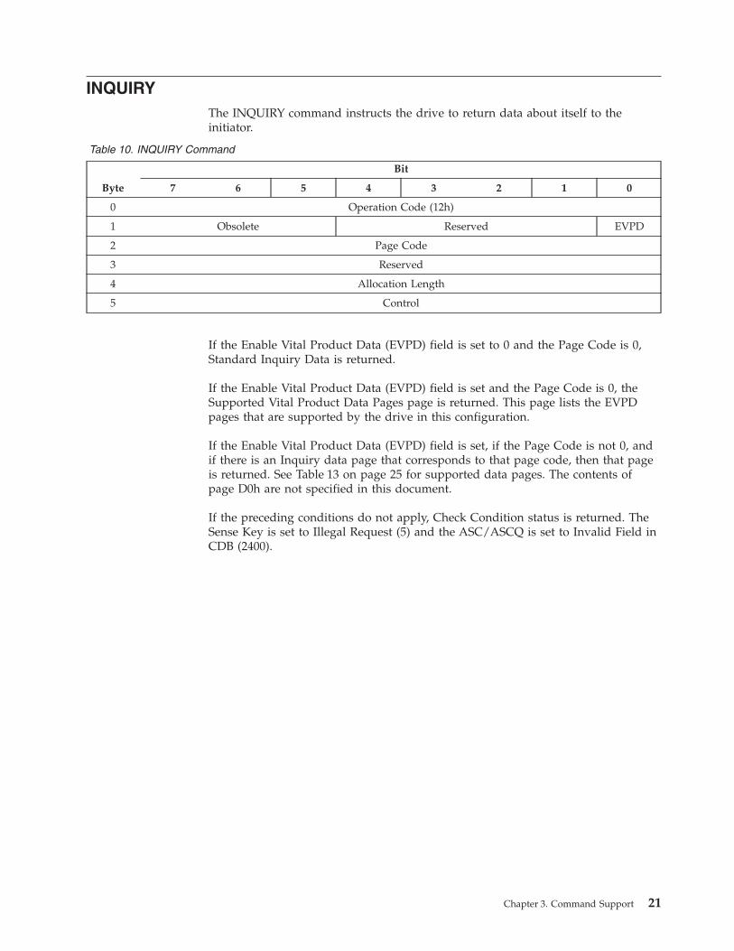
INQUIRY
The INQUIRY command instructs the drive to return data about itself to the
initiator.
Table 10. INQUIRY Command
Byte
Bit
7 6 5 4 3 2 1 0
0 Operation Code (12h)
1 Obsolete Reserved EVPD
2 Page Code
3 Reserved
4 Allocation Length
5 Control
If the Enable Vital Product Data (EVPD) field is set to 0 and the Page Code is 0,
Standard Inquiry Data is returned.
If the Enable Vital Product Data (EVPD) field is set and the Page Code is 0, the
Supported Vital Product Data Pages page is returned. This page lists the EVPD
pages that are supported by the drive in this configuration.
If the Enable Vital Product Data (EVPD) field is set, if the Page Code is not 0, and
if there is an Inquiry data page that corresponds to that page code, then that page
is returned. See Table 13 on page 25 for supported data pages. The contents of
page D0h are not specified in this document.
If the preceding conditions do not apply, Check Condition status is returned. The
Sense Key is set to Illegal Request (5) and the ASC/ASCQ is set to Invalid Field in
CDB (2400).
Chapter 3. Command Support 21
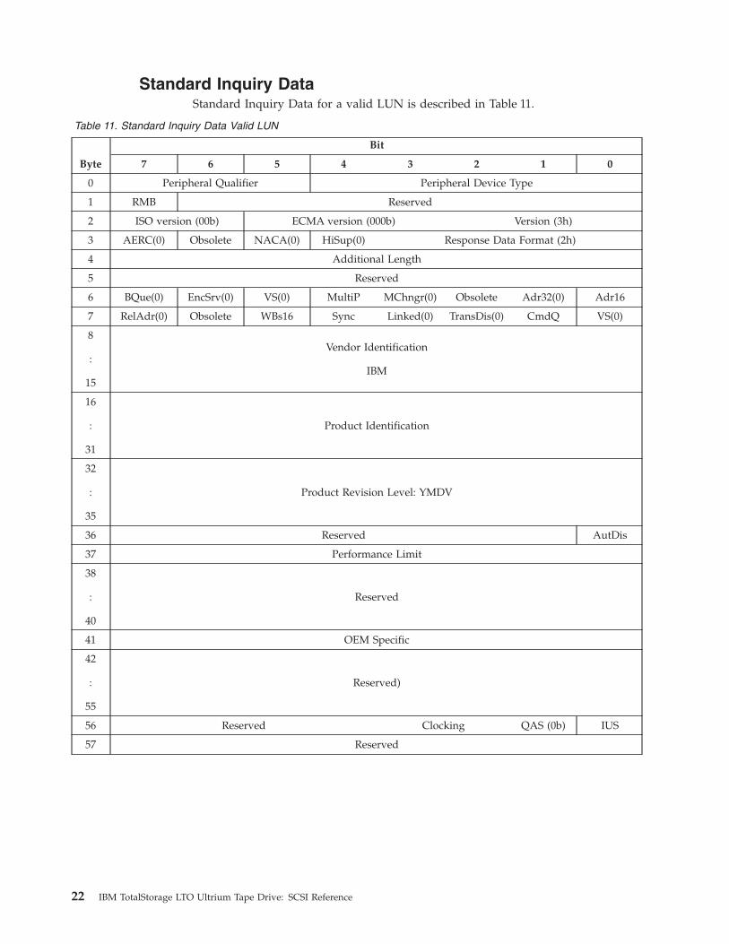
Standard Inquiry Data
Standard Inquiry Data for a valid LUN is described in Table 11.
Table 11. Standard Inquiry Data Valid LUN
Byte
Bit
7 6 5 4 3 2 1 0
0 Peripheral Qualifier Peripheral Device Type
1 RMB Reserved
2 ISO version (00b) ECMA version (000b) Version (3h)
3 AERC(0) Obsolete NACA(0) HiSup(0) Response Data Format (2h)
4 Additional Length
5 Reserved
6 BQue(0) EncSrv(0) VS(0) MultiP MChngr(0) Obsolete Adr32(0) Adr16
7 RelAdr(0) Obsolete WBs16 Sync Linked(0) TransDis(0) CmdQ VS(0)
8
:
15
Vendor Identification
IBM
16
:
31
Product Identification
32
:
35
Product Revision Level: YMDV
36 Reserved AutDis
37 Performance Limit
38
:
40
Reserved
41 OEM Specific
42
:
55
Reserved)
56 Reserved Clocking QAS (0b) IUS
57 Reserved
22 IBM TotalStorage LTO Ultrium Tape Drive: SCSI Reference
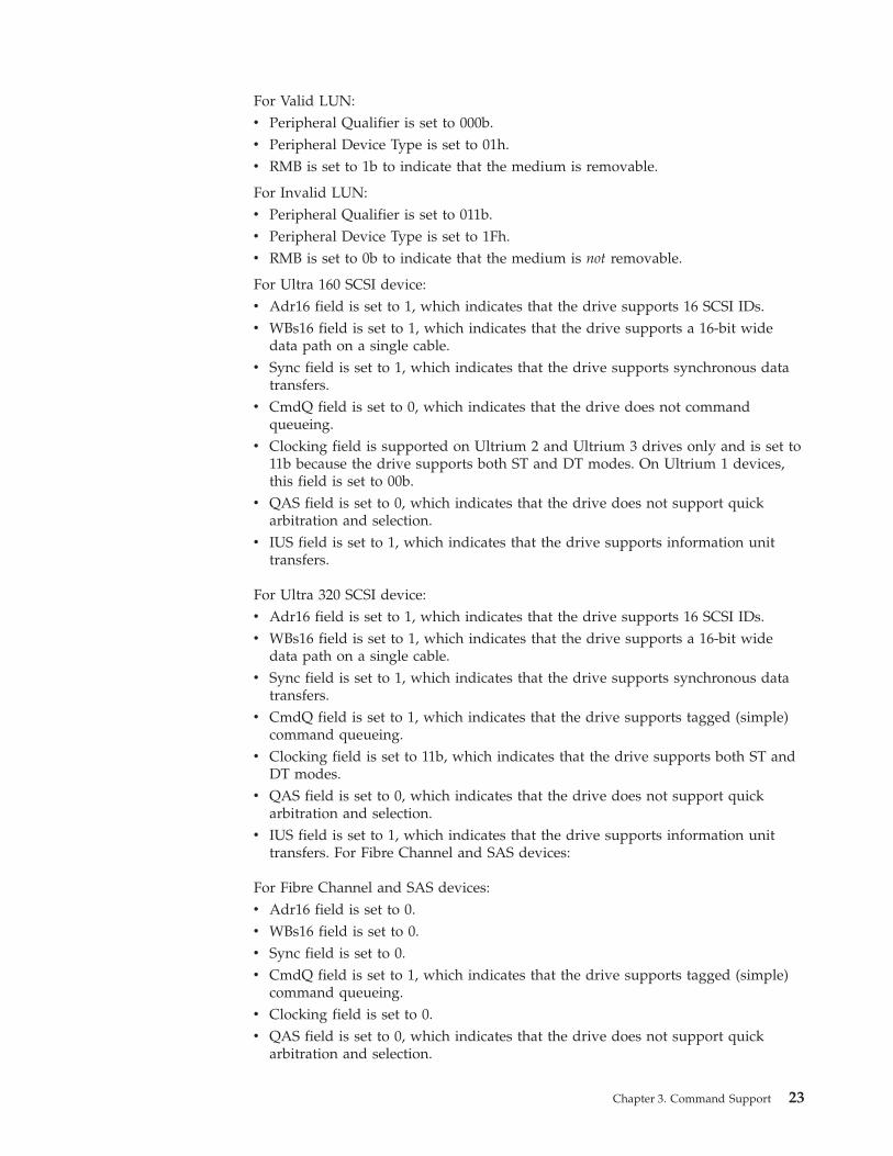
For Valid LUN:
v Peripheral Qualifier is set to 000b.
v Peripheral Device Type is set to 01h.
v RMB is set to 1b to indicate that the medium is removable.
For Invalid LUN:
v Peripheral Qualifier is set to 011b.
v Peripheral Device Type is set to 1Fh.
v RMB is set to 0b to indicate that the medium is not removable.
For Ultra 160 SCSI device:
v Adr16 field is set to 1, which indicates that the drive supports 16 SCSI IDs.
v WBs16 field is set to 1, which indicates that the drive supports a 16-bit wide
data path on a single cable.
v Sync field is set to 1, which indicates that the drive supports synchronous data
transfers.
v CmdQ field is set to 0, which indicates that the drive does not command
queueing.
v Clocking field is supported on Ultrium 2 and Ultrium 3 drives only and is set to
11b because the drive supports both ST and DT modes. On Ultrium 1 devices,
this field is set to 00b.
v QAS field is set to 0, which indicates that the drive does not support quick
arbitration and selection.
v IUS field is set to 1, which indicates that the drive supports information unit
transfers.
For Ultra 320 SCSI device:
v Adr16 field is set to 1, which indicates that the drive supports 16 SCSI IDs.
v WBs16 field is set to 1, which indicates that the drive supports a 16-bit wide
data path on a single cable.
v Sync field is set to 1, which indicates that the drive supports synchronous data
transfers.
v CmdQ field is set to 1, which indicates that the drive supports tagged (simple)
command queueing.
v Clocking field is set to 11b, which indicates that the drive supports both ST and
DT modes.
v QAS field is set to 0, which indicates that the drive does not support quick
arbitration and selection.
v IUS field is set to 1, which indicates that the drive supports information unit
transfers. For Fibre Channel and SAS devices:
For Fibre Channel and SAS devices:
v Adr16 field is set to 0.
v WBs16 field is set to 0.
v Sync field is set to 0.
v CmdQ field is set to 1, which indicates that the drive supports tagged (simple)
command queueing.
v Clocking field is set to 0.
v QAS field is set to 0, which indicates that the drive does not support quick
arbitration and selection.
Chapter 3. Command Support 23

v IUS field is set to 0, which indicates that the drive does not support information
unit transfers.
For all devices:
v The Additional Length field specifies how many bytes follow. Currently Ultrium
1 devices set this value to 33 (21h), and Ultrium 2 and Ultrium 3 devices set this
value to 53 (35h). This value is subject to change. It is strongly recommended
that the user parse the data returned by using the Additional Length field
instead of the published values.
v Vendor Identification returns IBM in ASCII with trailing blanks.
v Product Vendor Identification returns ULTxxxx-TDy in ASCII with trailing blanks.
If the drive is an IBM drive, xxxx equals 3580; if it is an OEM drive, xxxx equals
RIUM. The character y indicates the generation of the drive. See the table below
for the value returned.
Table 12. Product Identification Table
Generation IBM Drive OEM Drive
1 ULT3580-TD1 ULTRIUM-TD1
2 ULT3580-TD2 ULTRIUM-TD2
3 ULT3580-TD3 ULTRIUM-TD3
3 Half-Height ULT3580-HH3 ULTRIUM-HH3
4 ULT3580-TD4 ULTRIUM-TD4
v Product Revision Level has four parts:
– Y is the last character of the year (for example, 2 indicates the year 2002)
– M is the month, in the alphanumeric set 1 through 9, A, B, or C
– D is the day, in the alphanumeric set 1 through 9, A through V
– V is the version, in the alphanumeric set 0 through 9, A through Z, with 0
being the earliest and Z the latest (to avoid interpretation errors, the
characters i, l, and 0 are not used)v If the Performance Limit field is set to 0, the drive is a full performing drive. If
the Performing Limit field is set to a non-zero value, the Limit of the drive is
defined by the following equation:
Limit in MB/s = (Max Performance in MB/s) * ((Performance Limit) / 256)v Automation Disabled (AutDis) field set indicates that the drive is not capable of
full automation function. When this field is 0, it indicates that the drive is
capable of full automation function.
v The OEM Specific field is intentionally not specified. See the documentation
from the OEM vendor to determine the field’s definition and application.
24 IBM TotalStorage LTO Ultrium Tape Drive: SCSI Reference
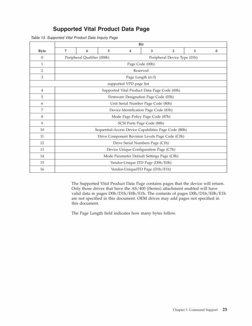
Supported Vital Product Data Page
Table 13. Supported Vital Product Data Inquiry Page
Byte
Bit
7 6 5 4 3 2 1 0
0 Peripheral Qualifier (000b) Peripheral Device Type (01h)
1 Page Code (00h)
2 Reserved
3 Page Length (n-3)
supported VPD page list
4 Supported Vital Product Data Page Code (00h)
5 Firmware Designation Page Code (03h)
6 Unit Serial Number Page Code (80h)
7 Device Identification Page Code (83h)
8 Mode Page Policy Page Code (87h)
9 SCSI Ports Page Code (88h)
10 Sequential-Access Device Capabilities Page Code (B0h)
11 Drive Component Revision Levels Page Code (C0h)
12 Drive Serial Numbers Page (C1h)
13 Device Unique Configuration Page (C7h)
14 Mode Parameter Default Settings Page (C8h)
15 Vendor-Unique ITD Page (D0h/E0h)
16 Vendor-UniqueITD Page (D1h/E1h)
The Supported Vital Product Data Page contains pages that the device will return.
Only those drives that have the AS/400 (iSeries) attachment enabled will have
valid data in pages D0h/D1h/E0h/E1h. The contents of pages D0h/D1h/E0h/E1h
are not specified in this document. OEM drives may add pages not specified in
this document.
The Page Length field indicates how many bytes follow.
Chapter 3. Command Support 25
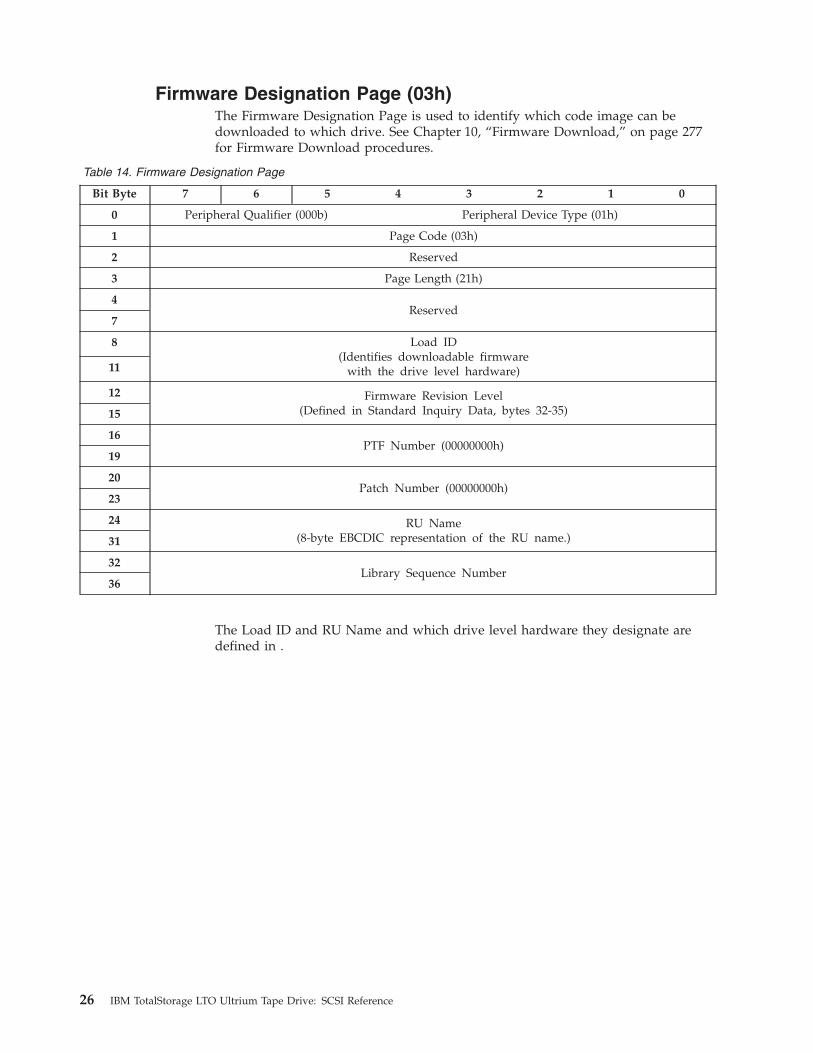
Firmware Designation Page (03h)
The Firmware Designation Page is used to identify which code image can be
downloaded to which drive. See Chapter 10, “Firmware Download,” on page 277
for Firmware Download procedures.
Table 14. Firmware Designation Page
Bit Byte 7 6 5 4 3 2 1 0
0 Peripheral Qualifier (000b) Peripheral Device Type (01h)
1 Page Code (03h)
2 Reserved
3 Page Length (21h)
4
Reserved
7
8 Load ID
(Identifies downloadable firmware
with the drive level hardware)
11
12 Firmware Revision Level
(Defined in Standard Inquiry Data, bytes 32-35) 15
16
PTF Number (00000000h)
19
20
Patch Number (00000000h)
23
24 RU Name
(8-byte EBCDIC representation of the RU name.) 31
32
Library Sequence Number
36
The Load ID and RU Name and which drive level hardware they designate are
defined in .
26 IBM TotalStorage LTO Ultrium Tape Drive: SCSI Reference
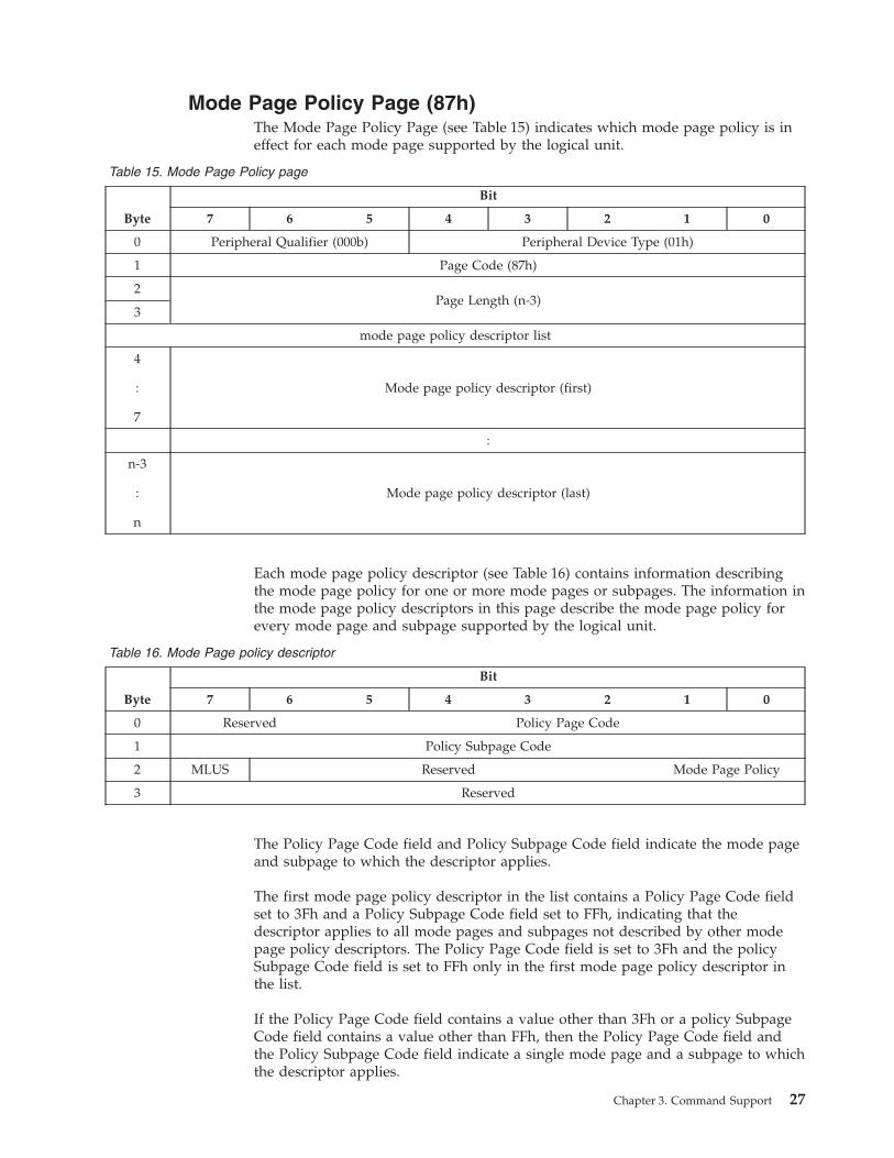
Mode Page Policy Page (87h)
The Mode Page Policy Page (see Table 15) indicates which mode page policy is in
effect for each mode page supported by the logical unit.
Table 15. Mode Page Policy page
Byte
Bit
7 6 5 4 3 2 1 0
0 Peripheral Qualifier (000b) Peripheral Device Type (01h)
1 Page Code (87h)
2
Page Length (n-3)
3
mode page policy descriptor list
4
:
7
Mode page policy descriptor (first)
:
n-3
:
n
Mode page policy descriptor (last)
Each mode page policy descriptor (see Table 16) contains information describing
the mode page policy for one or more mode pages or subpages. The information in
the mode page policy descriptors in this page describe the mode page policy for
every mode page and subpage supported by the logical unit.
Table 16. Mode Page policy descriptor
Byte
Bit
7 6 5 4 3 2 1 0
0 Reserved Policy Page Code
1 Policy Subpage Code
2 MLUS Reserved Mode Page Policy
3 Reserved
The Policy Page Code field and Policy Subpage Code field indicate the mode page
and subpage to which the descriptor applies.
The first mode page policy descriptor in the list contains a Policy Page Code field
set to 3Fh and a Policy Subpage Code field set to FFh, indicating that the
descriptor applies to all mode pages and subpages not described by other mode
page policy descriptors. The Policy Page Code field is set to 3Fh and the policy
Subpage Code field is set to FFh only in the first mode page policy descriptor in
the list.
If the Policy Page Code field contains a value other than 3Fh or a policy Subpage
Code field contains a value other than FFh, then the Policy Page Code field and
the Policy Subpage Code field indicate a single mode page and a subpage to which
the descriptor applies.
Chapter 3. Command Support 27
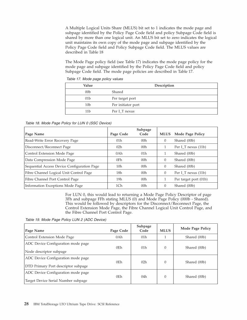
A Multiple Logical Units Share (MLUS) bit set to 1 indicates the mode page and
subpage identified by the Policy Page Code field and policy Subpage Code field is
shared by more than one logical unit. An MLUS bit set to zero indicates the logical
unit maintains its own copy of the mode page and subpage identified by the
Policy Page Code field and Policy Subpage Code field. The MLUS values are
described in Table 18
The Mode Page policy field (see Table 17) indicates the mode page policy for the
mode page and subpage identified by the Policy Page Code field and policy
Subpage Code field. The mode page policies are described in Table 17.
Table 17. Mode page policy values
Value Description
00b Shared
01b Per target port
10b Per initiator port
11b Per I_T nexus
Table 18. Mode Page Policy for LUN 0 (SSC Device)
Page Name Page Code
Subpage
Code MLUS Mode Page Policy
Read-Write Error Recovery Page 01h 00h 0 Shared (00b)
Disconnect/Reconnect Page 02h 00h 1 Per I_T nexus (11b)
Control Extension Mode Page 0Ah 01h 1 Shared (00b)
Data Compression Mode Page 0Fh 00h 0 Shared (00b)
Sequential Access Device Configuration Page 10h 00h 0 Shared (00b)
Fibre Channel Logical Unit Control Page 18h 00h 0 Per I_T nexus (11b)
Fibre Channel Port Control Page 19h 00h 1 Per target port (01b)
Information Exceptions Mode Page 1Ch 00h 0 Shared (00b)
For LUN 0, this would lead to returning a Mode Page Policy Descriptor of page
3Fh and subpage FFh stating MLUS (0) and Mode Page Policy (000b - Shared).
This would be followed by descriptors for the Disconnect/Reconnect Page, the
Control Extension Mode Page, the Fibre Channel Logical Unit Control Page, and
the Fibre Channel Port Control Page.
Table 19. Mode Page Policy LUN 2 (ADC Device)
Page Name Page Code
Subpage
Code MLUS
Mode Page Policy
Control Extension Mode Page 0Ah 01h 1 Shared (00b)
ADC Device Configuration mode page
Node descriptor subpage
0Eh 01h 0 Shared (00b)
ADC Device Configuration mode page
DTD Primary Port descriptor subpage
0Eh 02h 0 Shared (00b)
ADC Device Configuration mode page
Target Device Serial Number subpage
0Eh 04h 0 Shared (00b)
28 IBM TotalStorage LTO Ultrium Tape Drive: SCSI Reference

On LUN 2, this would lead to returning a Mode page Policy Descriptor of page
3Fh and subpage FFh stating MLUS (0) and Mode Page Policy (00b -Shared). This
would be followed by descriptors for the Control Extension Mode Page.
Chapter 3. Command Support 29
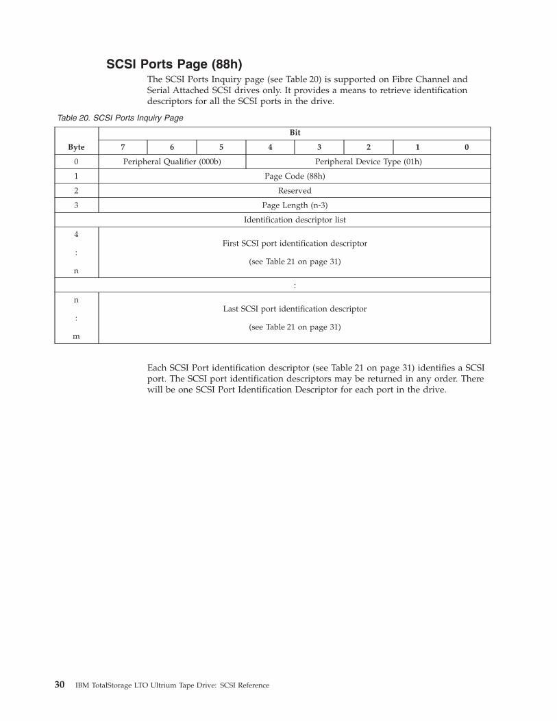
SCSI Ports Page (88h)
The SCSI Ports Inquiry page (see Table 20) is supported on Fibre Channel and
Serial Attached SCSI drives only. It provides a means to retrieve identification
descriptors for all the SCSI ports in the drive.
Table 20. SCSI Ports Inquiry Page
Byte
Bit
7 6 5 4 3 2 1 0
0 Peripheral Qualifier (000b) Peripheral Device Type (01h)
1 Page Code (88h)
2 Reserved
3 Page Length (n-3)
Identification descriptor list
4
:
n
First SCSI port identification descriptor
(see Table 21 on page 31)
:
n
:
m
Last SCSI port identification descriptor
(see Table 21 on page 31)
Each SCSI Port identification descriptor (see Table 21 on page 31) identifies a SCSI
port. The SCSI port identification descriptors may be returned in any order. There
will be one SCSI Port Identification Descriptor for each port in the drive.
30 IBM TotalStorage LTO Ultrium Tape Drive: SCSI Reference
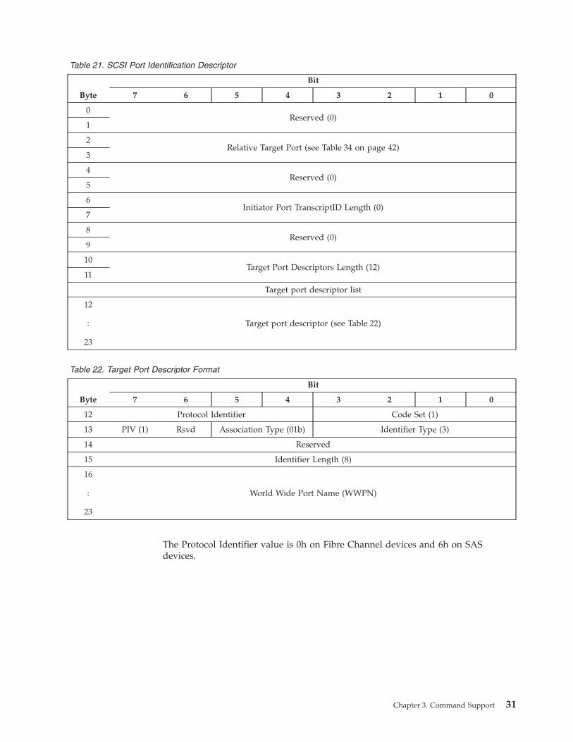
Table 21. SCSI Port Identification Descriptor
Byte
Bit
7 6 5 4 3 2 1 0
0
Reserved (0)
1
2
Relative Target Port (see Table 34 on page 42)
3
4
Reserved (0)
5
6
Initiator Port TranscriptID Length (0)
7
8
Reserved (0)
9
10
Target Port Descriptors Length (12)
11
Target port descriptor list
12
:
23
Target port descriptor (see Table 22)
Table 22. Target Port Descriptor Format
Byte
Bit
7 6 5 4 3 2 1 0
12 Protocol Identifier Code Set (1)
13 PIV (1) Rsvd Association Type (01b) Identifier Type (3)
14 Reserved
15 Identifier Length (8)
16
:
23
World Wide Port Name (WWPN)
The Protocol Identifier value is 0h on Fibre Channel devices and 6h on SAS
devices.
Chapter 3. Command Support 31

Sequential-Access Device Capabilities Page (B0h)
Table 23. Sequential-Access Device Capabilities Page
Byte
Bit
7 6 5 4 3 2 1 0
0 Peripheral Qualifier (000b) Peripheral Device Type (01h)
1 Page Code (B0h)
2
Page Length (2)
3
4 Reserved WORM
5 Reserved
The Write Once Read Many (WORM) bit is set to 1 on Ultrium 3 drives indicating
the drive supports WORM mode operation. The WORM bit is set to 0 on Ultrium
2 drives indicating the drive does not support WORM mode operation.
32 IBM TotalStorage LTO Ultrium Tape Drive: SCSI Reference
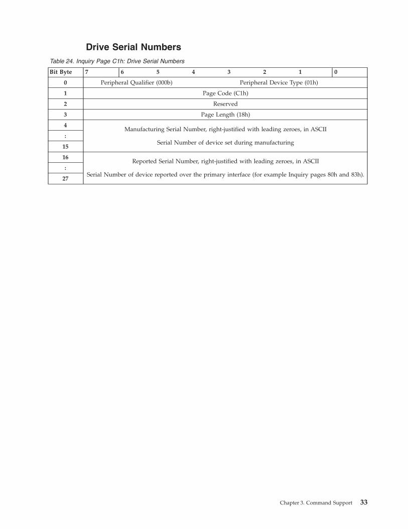
Drive Serial Numbers
Table 24. Inquiry Page C1h: Drive Serial Numbers
Bit Byte 7 6 5 4 3 2 1 0
0 Peripheral Qualifier (000b) Peripheral Device Type (01h)
1 Page Code (C1h)
2 Reserved
3 Page Length (18h)
4
Manufacturing Serial Number, right-justified with leading zeroes, in ASCII
Serial Number of device set during manufacturing
:
15
16
Reported Serial Number, right-justified with leading zeroes, in ASCII
Serial Number of device reported over the primary interface (for example Inquiry pages 80h and 83h).
:
27
Chapter 3. Command Support 33

Device Unique Configuration Data Page (C7h)
The Device Unique Configuration Data Page is supported on IBM eServer™ capable
drives only. On drives that are not eServer capable this page will be returned with
all zero data.
Table 25. Device Unique Configuration Data Page (C7h)
Byte
Bit
7 6 5 4 3 2 1 0
00 Peripheral Qualifier (0h) Peripheral Device Type (1h)
01 Page Code (C7h)
02 Reserved
03 Page Length (71h)
04 ASCII Length (04h)
05
SCDD Signature (“SCDD”)
08
09 Max Supported LUNs (00h)
10 (MSB)
Native Capacity in MB (00061A80h)
13 (LSB)
14 Rsvd SFM (0) SAVPG (0)
AUTSNS0 - PSCSI1 - SAS
ACA (0) FLQUE (0)
CRDFRU
(0)
MICDWN
(1)
15 Reserved
16 (MSB)
Max Microcode Download Transfer Length (49999Ah)
18 (LSB)
19 (MSB) Max Queue Depth00 01h - pSCSI00 1Eh - SAS
20 (LSB)
21 (MSB)
SCSI Reset Delay Time (0000FAh)
23
24 (MSB)
Max Block Transfer Size per SCSI Command (FFFFFFh)
26 (LSB)
27 Drive Technology (06h) (Half-Inch Cartridge)
28 Device Interface Field07h - pSCSI08h - SAS
29 (MSB)
Test Media P/N (12 ASCII characters) (″23R7042øøøøø″)
40 (LSB)
41 Cleaning Code Page (3Ch)
42 Trace Buffer ID (01h)
43 No. of Densities Supporting Write/Read (02h)
44 Write/Read Density 1 (42h)
45 Write/Read Density 2 (44h)
46 No. of Supported Densities (Read Only) (01h)
47 Read Only Density 1 (40h)
48 Read Only Density 2 (00h)
34 IBM TotalStorage LTO Ultrium Tape Drive: SCSI Reference

Table 25. Device Unique Configuration Data Page (C7h) (continued)
Byte
Bit
7 6 5 4 3 2 1 0
49 Read Only Density 3 (00h)
50 Read Only Density 4 (00h)
51 Read Only Density 5 (00h)
52 Read Only Density 6 (00h)
53 Read Only Density 7 (00h)
54 RSVD SFM (0)
MEMDMP(1)
STSTPG(1)
DIAGSR(0)
RETEN(0)
RDCMP(0)
WRCMP(1)
55 Reserved
56 (MSB)
Erase Command Timeout - Seconds (3BC4h)
57 (LSB)
58 (MSB)
Load/Unload Timeout - Seconds (0348h)
59 (LSB)
60 (MSB)
Locate Command Timeout - Seconds (3DE0h)
61 (LSB)
62 (MSB)
Rewind Command Timeout - Seconds (030Ch)
63 (LSB)
64 (MSB)
Space Command Timeout - Seconds (3DE0h)
65 (LSB)
66 (MSB)
Write Filemarks Command Timeout - Seconds (0564h)
67 (LSB)
68 (MSB)
Read/Write Command Timeout - Seconds (05A0h)
69 (LSB)
70 (MSB)
Write Buffer Timeout - Seconds (0294h)
71 (LSB)
72 (MSB)
Read Buffer Timeout - Seconds (0258h)
73 (LSB)
74 (MSB)
Receive Diagnostic Results Command Timeout - Seconds (003Ch)
75 (LSB)
76 (MSB)
Send Diagnostics Command Timeout - Seconds (0960h)
77 (LSB)
78 (MSB)
Reserved
81 (LSB)
82 (MSB)
Reserved
87 (LSB)
88 1st Operating System Parameter Count (05h)
89 (MSB)
1st Operating System Identifier in ASCII characters (“AIX”)
91 (LSB)
92 (MSB)
Reserved for other Operating System Identifiers (20202020h)
95 (LSB)
Chapter 3. Command Support 35
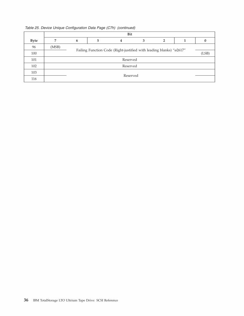
Table 25. Device Unique Configuration Data Page (C7h) (continued)
Byte
Bit
7 6 5 4 3 2 1 0
96 (MSB)
Failing Function Code (Right-justified with leading blanks) “ø2617”
100 (LSB)
101 Reserved
102 Reserved
103
Reserved
116
36 IBM TotalStorage LTO Ultrium Tape Drive: SCSI Reference
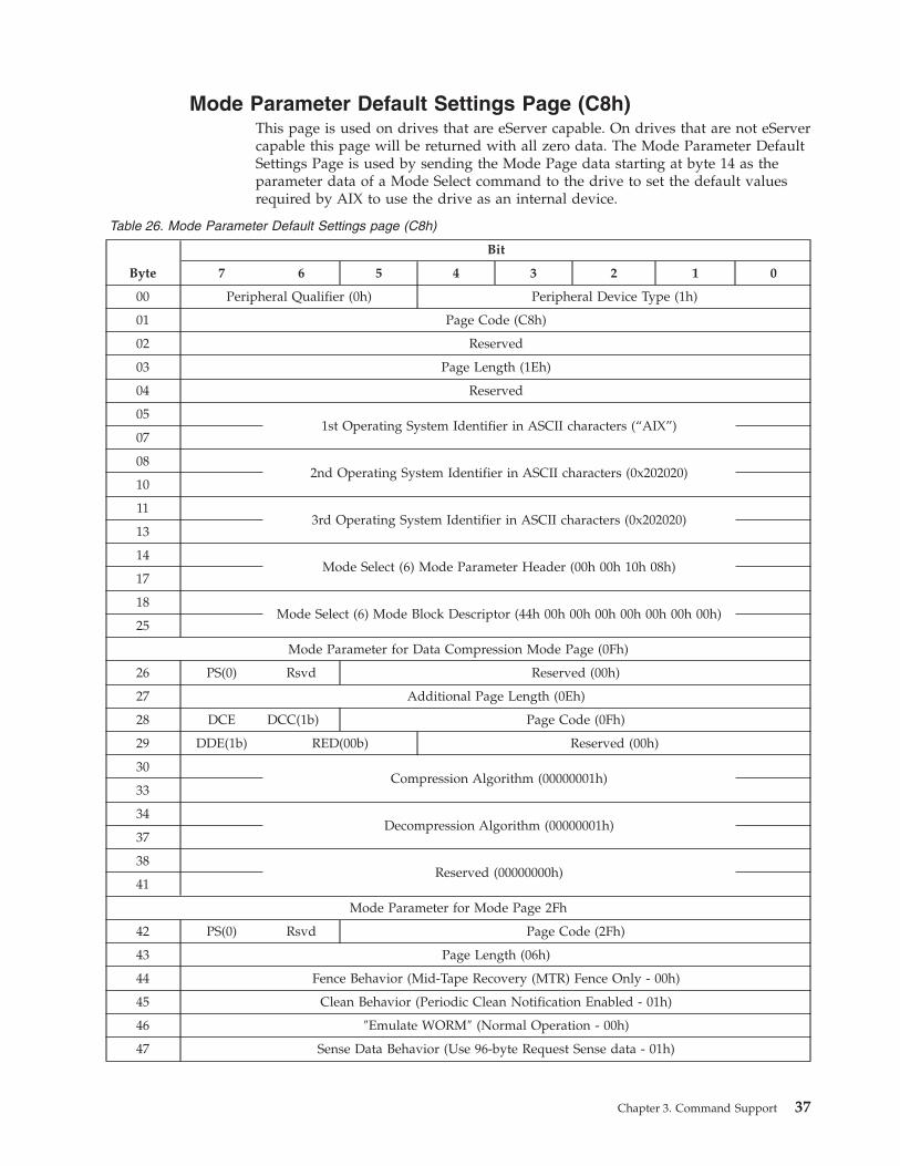
Mode Parameter Default Settings Page (C8h)
This page is used on drives that are eServer capable. On drives that are not eServer
capable this page will be returned with all zero data. The Mode Parameter Default
Settings Page is used by sending the Mode Page data starting at byte 14 as the
parameter data of a Mode Select command to the drive to set the default values
required by AIX to use the drive as an internal device.
Table 26. Mode Parameter Default Settings page (C8h)
Byte
Bit
7 6 5 4 3 2 1 0
00 Peripheral Qualifier (0h) Peripheral Device Type (1h)
01 Page Code (C8h)
02 Reserved
03 Page Length (1Eh)
04 Reserved
05
1st Operating System Identifier in ASCII characters (“AIX”)
07
08
2nd Operating System Identifier in ASCII characters (0x202020)
10
11
3rd Operating System Identifier in ASCII characters (0x202020)
13
14
Mode Select (6) Mode Parameter Header (00h 00h 10h 08h)
17
18
Mode Select (6) Mode Block Descriptor (44h 00h 00h 00h 00h 00h 00h 00h)
25
Mode Parameter for Data Compression Mode Page (0Fh)
26 PS(0) Rsvd Reserved (00h)
27 Additional Page Length (0Eh)
28 DCE DCC(1b) Page Code (0Fh)
29 DDE(1b) RED(00b) Reserved (00h)
30
Compression Algorithm (00000001h)
33
34
Decompression Algorithm (00000001h)
37
38
Reserved (00000000h)
41
Mode Parameter for Mode Page 2Fh
42 PS(0) Rsvd Page Code (2Fh)
43 Page Length (06h)
44 Fence Behavior (Mid-Tape Recovery (MTR) Fence Only - 00h)
45 Clean Behavior (Periodic Clean Notification Enabled - 01h)
46 ″Emulate WORM″ (Normal Operation - 00h)
47 Sense Data Behavior (Use 96-byte Request Sense data - 01h)
Chapter 3. Command Support 37
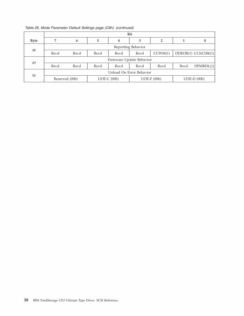
Table 26. Mode Parameter Default Settings page (C8h) (continued)
Byte
Bit
7 6 5 4 3 2 1 0
48
Reporting Behavior
Rsvd Rsvd Rsvd Rsvd Rsvd CCWM(1) DDEOR(1) CLNCHK(1)
49
Firmware Update Behavior
Rsvd Rsvd Rsvd Rsvd Rsvd Rsvd Rsvd DFMRDL(1)
50
Unload On Error Behavior
Reserved (00b) UOE-C (00b) UOE-F (00b) UOE-D (00b)
38 IBM TotalStorage LTO Ultrium Tape Drive: SCSI Reference

Unit Serial Number Page
Table 27. Unit Serial Number Inquiry Page
Byte
Bit
7 6 5 4 3 2 1 0
0 Peripheral Qualifier (000b) Peripheral Device Type (01h)
1 Page Code (80h)
2 Reserved
3 Page Length (0Ah)
4
:
13
Unit Serial Number
The Unit Serial Number Page contains a single value that is a 10-byte ASCII string.
The string, with the Vendor Identification and Product Identification fields in the
Standard Inquiry Data, uniquely identifies the drive. Valid Serial Number values
are 0 through 9, A through D, and F. On eServer enabled drives this is the last 10
characters of the 11S identifier
Chapter 3. Command Support 39
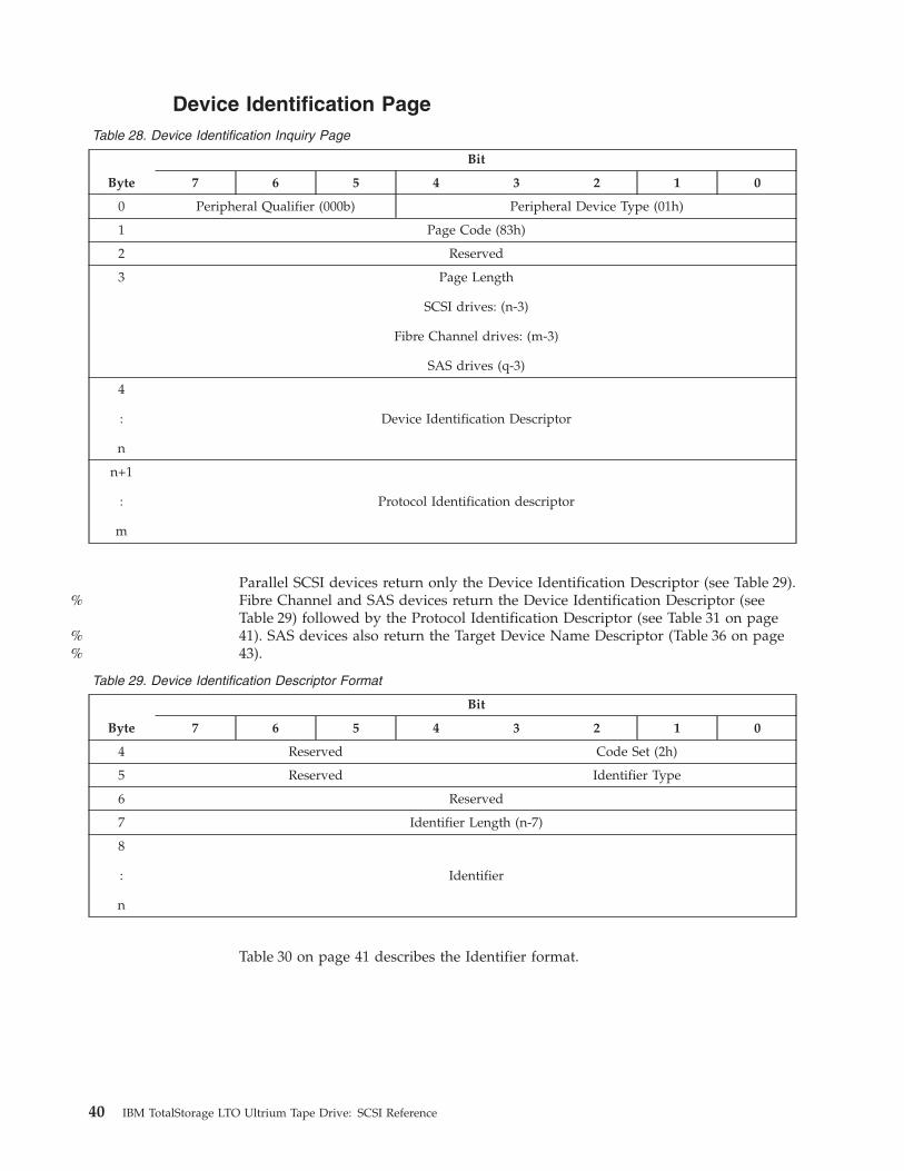
Device Identification Page
Table 28. Device Identification Inquiry Page
Byte
Bit
7 6 5 4 3 2 1 0
0 Peripheral Qualifier (000b) Peripheral Device Type (01h)
1 Page Code (83h)
2 Reserved
3 Page Length
SCSI drives: (n-3)
Fibre Channel drives: (m-3)
SAS drives (q-3)
4
:
n
Device Identification Descriptor
n+1
:
m
Protocol Identification descriptor
Parallel SCSI devices return only the Device Identification Descriptor (see Table 29).
Fibre Channel and SAS devices return the Device Identification Descriptor (see
Table 29) followed by the Protocol Identification Descriptor (see Table 31 on page
41). SAS devices also return the Target Device Name Descriptor (Table 36 on page
43).
Table 29. Device Identification Descriptor Format
Byte
Bit
7 6 5 4 3 2 1 0
4 Reserved Code Set (2h)
5 Reserved Identifier Type
6 Reserved
7 Identifier Length (n-7)
8
:
n
Identifier
Table 30 on page 41 describes the Identifier format.
40 IBM TotalStorage LTO Ultrium Tape Drive: SCSI Reference
%
%%
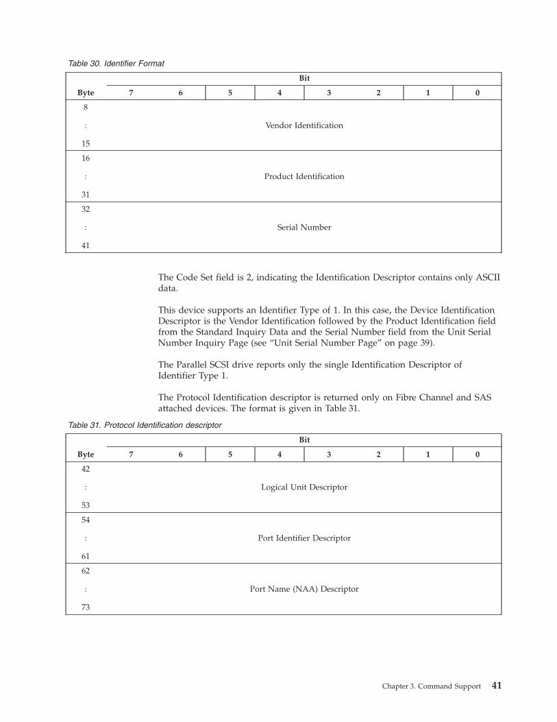
Table 30. Identifier Format
Byte
Bit
7 6 5 4 3 2 1 0
8
:
15
Vendor Identification
16
:
31
Product Identification
32
:
41
Serial Number
The Code Set field is 2, indicating the Identification Descriptor contains only ASCII
data.
This device supports an Identifier Type of 1. In this case, the Device Identification
Descriptor is the Vendor Identification followed by the Product Identification field
from the Standard Inquiry Data and the Serial Number field from the Unit Serial
Number Inquiry Page (see “Unit Serial Number Page” on page 39).
The Parallel SCSI drive reports only the single Identification Descriptor of
Identifier Type 1.
The Protocol Identification descriptor is returned only on Fibre Channel and SAS
attached devices. The format is given in Table 31.
Table 31. Protocol Identification descriptor
Byte
Bit
7 6 5 4 3 2 1 0
42
:
53
Logical Unit Descriptor
54
:
61
Port Identifier Descriptor
62
:
73
Port Name (NAA) Descriptor
Chapter 3. Command Support 41
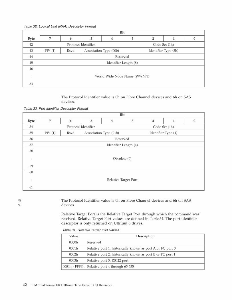
Table 32. Logical Unit (NAA) Descriptor Format
Byte
Bit
7 6 5 4 3 2 1 0
42 Protocol Identifier Code Set (1h)
43 PIV (1) Rsvd Association Type (00b) Identifier Type (3h)
44 Reserved
45 Identifier Length (8)
46
:
53
World Wide Node Name (WWNN)
The Protocol Identifier value is 0h on Fibre Channel devices and 6h on SAS
devices.
Table 33. Port Identifier Descriptor Format
Byte
Bit
7 6 5 4 3 2 1 0
54 Protocol Identifier Code Set (1h)
55 PIV (1) Rsvd Association Type (01b) Identifier Type (4)
56 Reserved
57 Identifier Length (4)
58
:
59
Obsolete (0)
60
:
61
Relative Target Port
The Protocol Identifier value is 0h on Fibre Channel devices and 6h on SAS
devices.
Relative Target Port is the Relative Target Port through which the command was
received. Relative Target Port values are defined in Table 34. The port identifier
descriptor is only returned on Ultrium 3 drives.
Table 34. Relative Target Port Values
Value Description
0000h Reserved
0001h Relative port 1, historically known as port A or FC port 0
0002h Relative port 2, historically known as port B or FC port 1
0003h Relative port 3, RS422 port
0004h - FFFFh Relative port 4 through 65 535
42 IBM TotalStorage LTO Ultrium Tape Drive: SCSI Reference
%%
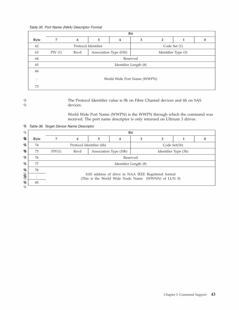
Table 35. Port Name (NAA) Descriptor Format
Byte
Bit
7 6 5 4 3 2 1 0
62 Protocol Identifier Code Set (1)
63 PIV (1) Rsvd Association Type (01b) Identifier Type (3)
64 Reserved
65 Identifier Length (8)
66
:
73
World Wide Port Name (WWPN)
The Protocol Identifier value is 0h on Fibre Channel devices and 6h on SAS
devices.
World Wide Port Name (WWPN) is the WWPN through which the command was
received. The port name descriptor is only returned on Ultrium 3 drives.
Table 36. Target Device Name Descriptor
Byte
Bit
7 6 5 4 3 2 1 0
74 Protocol Identifier (6h) Code Set(1h)
75 PIV(1) Rsvd Association Type (10b) Identifier Type (3h)
76 Reserved
77 Identifier Length (8)
78
SAS address of drive in NAA IEEE Registered format
(This is the World Wide Node Name (WWNN) of LUN 0)
:
85
Chapter 3. Command Support 43
%%
%%
%
%
%%%%%%%%
%%%
%%%%%
%%
%%
%%%%
%
%%%
%%%%
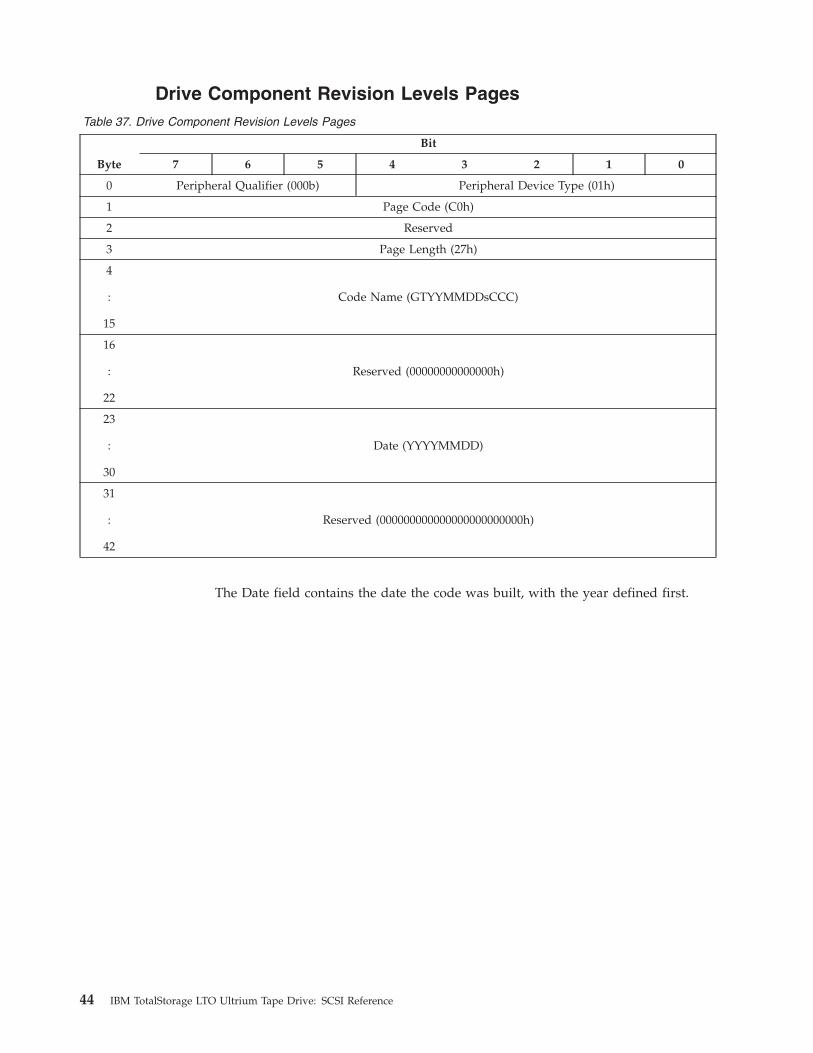
Drive Component Revision Levels Pages
Table 37. Drive Component Revision Levels Pages
Byte
Bit
7 6 5 4 3 2 1 0
0 Peripheral Qualifier (000b) Peripheral Device Type (01h)
1 Page Code (C0h)
2 Reserved
3 Page Length (27h)
4
:
15
Code Name (GTYYMMDDsCCC)
16
:
22
Reserved (00000000000000h)
23
:
30
Date (YYYYMMDD)
31
:
42
Reserved (000000000000000000000000h)
The Date field contains the date the code was built, with the year defined first.
44 IBM TotalStorage LTO Ultrium Tape Drive: SCSI Reference
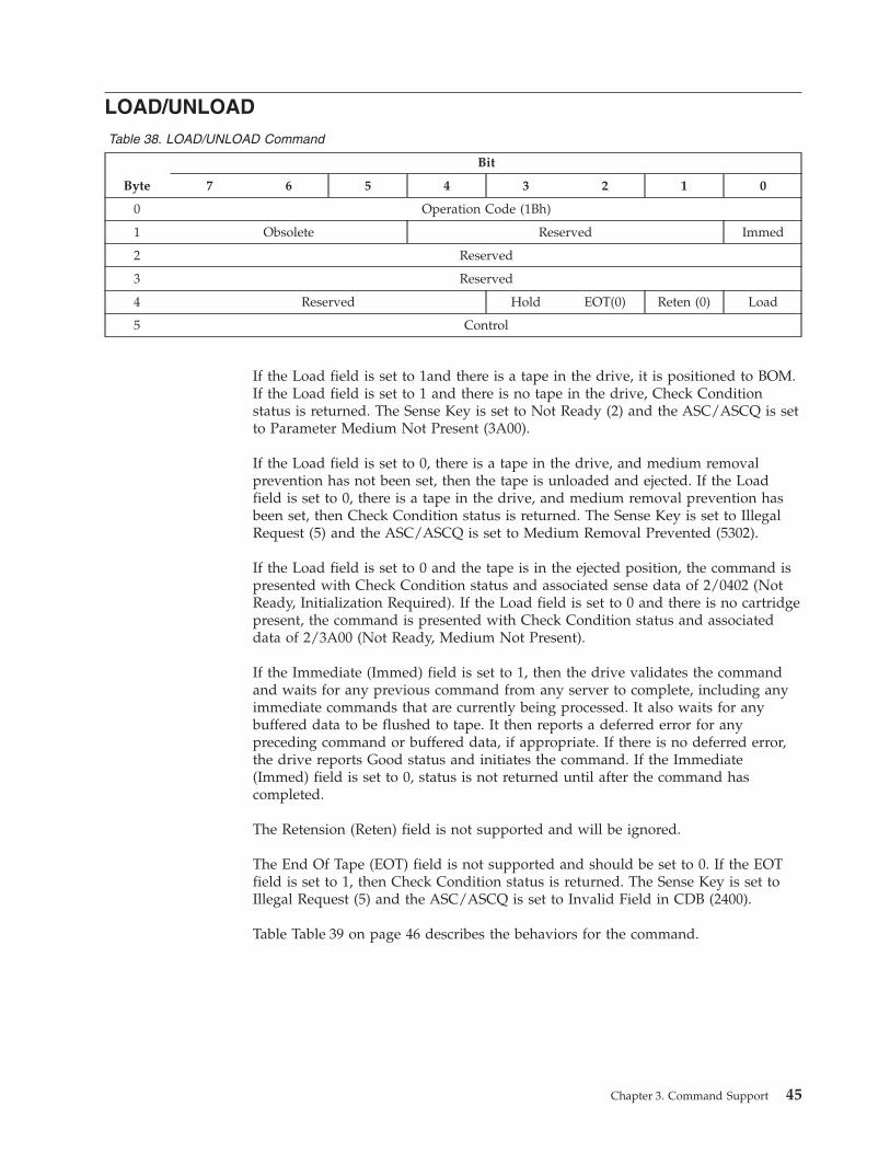
LOAD/UNLOAD
Table 38. LOAD/UNLOAD Command
Byte
Bit
7 6 5 4 3 2 1 0
0 Operation Code (1Bh)
1 Obsolete Reserved Immed
2 Reserved
3 Reserved
4 Reserved Hold EOT(0) Reten (0) Load
5 Control
If the Load field is set to 1and there is a tape in the drive, it is positioned to BOM.
If the Load field is set to 1 and there is no tape in the drive, Check Condition
status is returned. The Sense Key is set to Not Ready (2) and the ASC/ASCQ is set
to Parameter Medium Not Present (3A00).
If the Load field is set to 0, there is a tape in the drive, and medium removal
prevention has not been set, then the tape is unloaded and ejected. If the Load
field is set to 0, there is a tape in the drive, and medium removal prevention has
been set, then Check Condition status is returned. The Sense Key is set to Illegal
Request (5) and the ASC/ASCQ is set to Medium Removal Prevented (5302).
If the Load field is set to 0 and the tape is in the ejected position, the command is
presented with Check Condition status and associated sense data of 2/0402 (Not
Ready, Initialization Required). If the Load field is set to 0 and there is no cartridge
present, the command is presented with Check Condition status and associated
data of 2/3A00 (Not Ready, Medium Not Present).
If the Immediate (Immed) field is set to 1, then the drive validates the command
and waits for any previous command from any server to complete, including any
immediate commands that are currently being processed. It also waits for any
buffered data to be flushed to tape. It then reports a deferred error for any
preceding command or buffered data, if appropriate. If there is no deferred error,
the drive reports Good status and initiates the command. If the Immediate
(Immed) field is set to 0, status is not returned until after the command has
completed.
The Retension (Reten) field is not supported and will be ignored.
The End Of Tape (EOT) field is not supported and should be set to 0. If the EOT
field is set to 1, then Check Condition status is returned. The Sense Key is set to
Illegal Request (5) and the ASC/ASCQ is set to Invalid Field in CDB (2400).
Table Table 39 on page 46 describes the behaviors for the command.
Chapter 3. Command Support 45
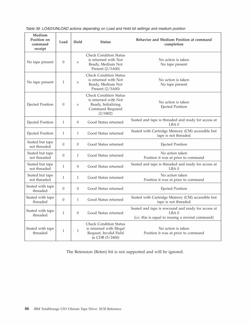
Table 39. LOAD/UNLOAD actions depending on Load and Hold bit settings and medium position
Medium
Position on
command
receipt
Load Hold Statue
Behavior and Medium Position at command
completion
No tape present 0 x
Check Condition Status
is returned with Not
Ready, Medium Not
Present (2/3A00)
No action is takenNo tape present
No tape present 1 x
Check Condition Status
is returned with Not
Ready, Medium Not
Present (2/3A00)
No action is takenNo tape present
Ejected Position 0 x
Check Condition Status
is returned with Not
Ready, Initializing
Command Required
(2/0402)
No action is taken
Ejected Position
Ejected Position 1 0 Good Status returned
Seated and tape is threaded and ready for access at
LBA 0
Ejected Position 1 1 Good Status returned
Seated with Cartridge Memory (CM) accessible but
tape is not threaded
Seated but tape
not threaded
0 0 Good Status returned Ejected Position
Seated but tape
not threaded
0 1 Good Status returned
No action takenPosition it was at prior to command
Seated but tape
not threaded
1 0 Good Status returned
Seated and tape is threaded and ready for access at
LBA 0
Seated but tape
not threaded
1 1 Good Status returned
No action takenPosition it was at prior to command
Seated with tape
threaded
0 0 Good Status returned Ejected Position
Seated with tape
threaded
0 1 Good Status returned
Seated with Cartridge Memory (CM) accessible but
tape is not threaded
Seated with tape
threaded
1 0 Good Status returned
Seated and tape is rewound and ready for access at
LBA 0(i.e. this is equal to issuing a rewind command)
Seated with tape
threaded
1 1
Check Condition Status
is returned with Illegal
Request, Invalid Field
in CDB (5/2400)
No action is taken
Position it was at prior to command
The Retension (Reten) bit is not supported and will be ignored.
46 IBM TotalStorage LTO Ultrium Tape Drive: SCSI Reference

LOCATE
The LOCATE command causes the logical position on tape to be set to the value
indicated by the Block Address field. The value indicates the total number of
records and marks between BOM and the desired logical position. A value of 0
causes the tape to be positioned at BOM.
Table 40. LOCATE (10) command
Byte
Bit
7 6 5 4 3 2 1 0
0 Operation Code (2Bh)
1 Obsolete Reserved BT(0) CP(0) Immed
2 Reserved
3
:
6
Block Address
7 Reserved
8 Partition (0)
9 Control
Table 41. LOCATE(16) Command (Ultrium 4 and Later)
Byte
Bit
7 6 5 4 3 2 1 0
0 Operation Code (92Bh)
1 Reserved Dest_Type Rsvd CP (0) IMMED
2 Reserved BAM (0)
3 Partition (00h)
4 (MSB)
Block Address
11 (LSB)
12
Reserved
14
15 Control
If the Immediate (Immed) field is set to 1, then the drive validates the command
and waits for any previous command from any server to complete, including any
immediate commands that are currently being processed. It also waits for any
buffered data to be flushed to tape. It then reports a deferred error for any
preceding command or buffered data, if appropriate. If there is no deferred error,
the drive reports Good status and initiates the command. If the Immediate
(Immed) field is set to 0, status is not returned until after the command has
completed.
If the LOCATE command fails for anything other than Illegal Request, the logical
position is not guaranteed and a READ POSITION command should be issued to
determine the current logical position of the tape.
Chapter 3. Command Support 47
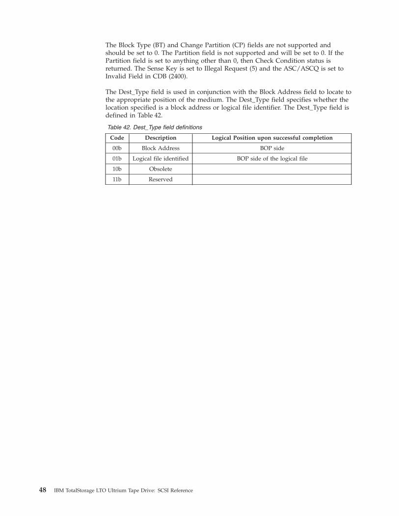
The Block Type (BT) and Change Partition (CP) fields are not supported and
should be set to 0. The Partition field is not supported and will be set to 0. If the
Partition field is set to anything other than 0, then Check Condition status is
returned. The Sense Key is set to Illegal Request (5) and the ASC/ASCQ is set to
Invalid Field in CDB (2400).
The Dest_Type field is used in conjunction with the Block Address field to locate to
the appropriate position of the medium. The Dest_Type field specifies whether the
location specified is a block address or logical file identifier. The Dest_Type field is
defined in Table 42.
Table 42. Dest_Type field definitions
Code Description Logical Position upon successful completion
00b Block Address BOP side
01b Logical file identified BOP side of the logical file
10b Obsolete
11b Reserved
48 IBM TotalStorage LTO Ultrium Tape Drive: SCSI Reference
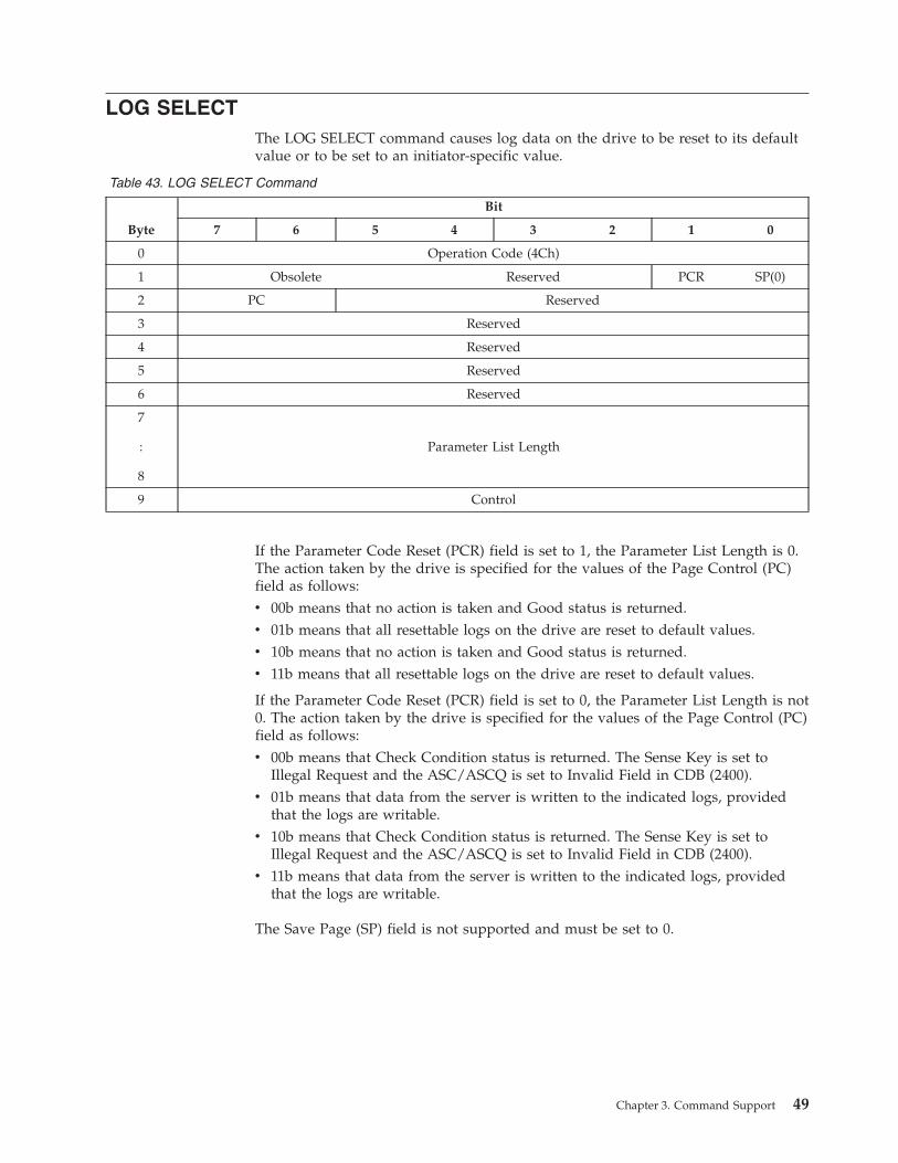
LOG SELECT
The LOG SELECT command causes log data on the drive to be reset to its default
value or to be set to an initiator-specific value.
Table 43. LOG SELECT Command
Byte
Bit
7 6 5 4 3 2 1 0
0 Operation Code (4Ch)
1 Obsolete Reserved PCR SP(0)
2 PC Reserved
3 Reserved
4 Reserved
5 Reserved
6 Reserved
7
:
8
Parameter List Length
9 Control
If the Parameter Code Reset (PCR) field is set to 1, the Parameter List Length is 0.
The action taken by the drive is specified for the values of the Page Control (PC)
field as follows:
v 00b means that no action is taken and Good status is returned.
v 01b means that all resettable logs on the drive are reset to default values.
v 10b means that no action is taken and Good status is returned.
v 11b means that all resettable logs on the drive are reset to default values.
If the Parameter Code Reset (PCR) field is set to 0, the Parameter List Length is not
0. The action taken by the drive is specified for the values of the Page Control (PC)
field as follows:
v 00b means that Check Condition status is returned. The Sense Key is set to
Illegal Request and the ASC/ASCQ is set to Invalid Field in CDB (2400).
v 01b means that data from the server is written to the indicated logs, provided
that the logs are writable.
v 10b means that Check Condition status is returned. The Sense Key is set to
Illegal Request and the ASC/ASCQ is set to Invalid Field in CDB (2400).
v 11b means that data from the server is written to the indicated logs, provided
that the logs are writable.
The Save Page (SP) field is not supported and must be set to 0.
Chapter 3. Command Support 49

LOG SENSE
The LOG SENSE command causes log data to be sent to the initiator.
Table 44. LOG SENSE Command
Byte
Bit
7 6 5 4 3 2 1 0
0 Operation Code (4Dh)
1 Obsolete Reserved PPC(0) SP(0)
2 PC Page Code
3 Reserved
4 Reserved
5
:
6
Parameter Pointer (0)
7
:
8
Allocation Length
9 Control
The log values returned are controlled by the Page Control (PC) field value as
follows:
v 00b means that the maximum value for each log entry is returned.
Note: For page 2Eh (TapeAlert) only, the PC field is ignored. Current® values
are always returned.
v 01b means that the current values are returned.
v 10b means that the maximum value for each log entry is returned.
v 11b means that the power-on values are returned.
The Parameter Pointer Control (PPC) must be set to 0. Returning changed
parameters is not supported. The Save Page (SP) field must be set to 0. Saved
pages are not supported. The Parameter Pointer will be 0.
Cartridge-specific log parameter counts are set to 0 when a cartridge has
successfully loaded.
WARNING
Log parameter data must be dynamically parsed as some parameters may not
be present and other parameters may be inserted. The relative location of
parameters have changed and are anticipated to continue to change.
50 IBM TotalStorage LTO Ultrium Tape Drive: SCSI Reference
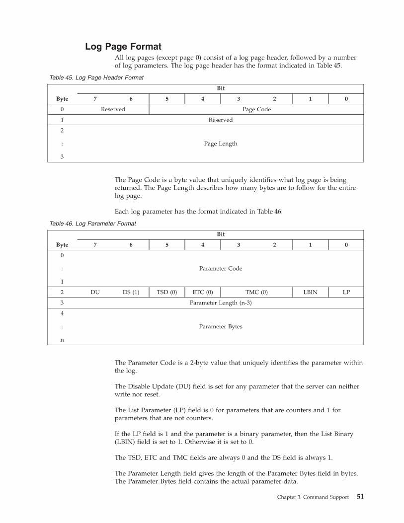
Log Page Format
All log pages (except page 0) consist of a log page header, followed by a number
of log parameters. The log page header has the format indicated in Table 45.
Table 45. Log Page Header Format
Byte
Bit
7 6 5 4 3 2 1 0
0 Reserved Page Code
1 Reserved
2
:
3
Page Length
The Page Code is a byte value that uniquely identifies what log page is being
returned. The Page Length describes how many bytes are to follow for the entire
log page.
Each log parameter has the format indicated in Table 46.
Table 46. Log Parameter Format
Byte
Bit
7 6 5 4 3 2 1 0
0
:
1
Parameter Code
2 DU DS (1) TSD (0) ETC (0) TMC (0) LBIN LP
3 Parameter Length (n-3)
4
:
n
Parameter Bytes
The Parameter Code is a 2-byte value that uniquely identifies the parameter within
the log.
The Disable Update (DU) field is set for any parameter that the server can neither
write nor reset.
The List Parameter (LP) field is 0 for parameters that are counters and 1 for
parameters that are not counters.
If the LP field is 1 and the parameter is a binary parameter, then the List Binary
(LBIN) field is set to 1. Otherwise it is set to 0.
The TSD, ETC and TMC fields are always 0 and the DS field is always 1.
The Parameter Length field gives the length of the Parameter Bytes field in bytes.
The Parameter Bytes field contains the actual parameter data.
Chapter 3. Command Support 51
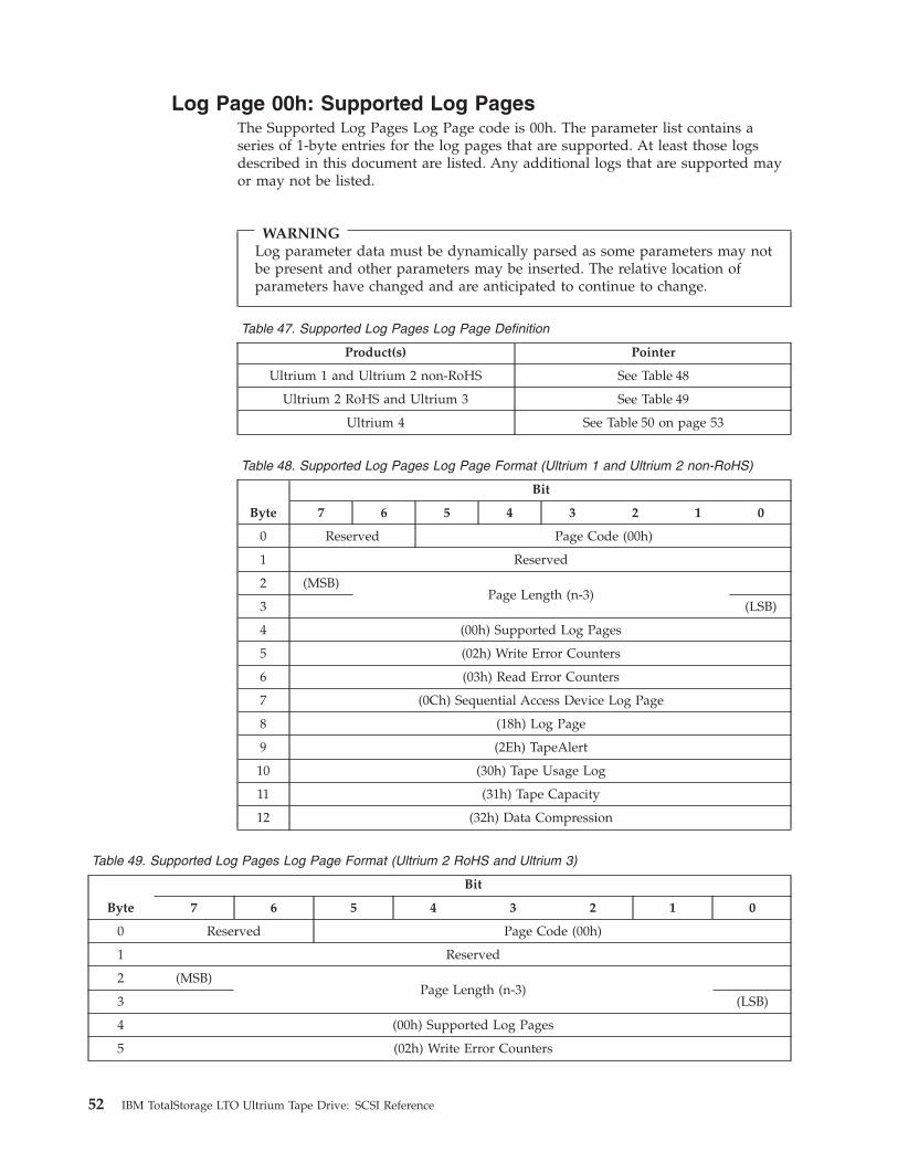
Log Page 00h: Supported Log Pages
The Supported Log Pages Log Page code is 00h. The parameter list contains a
series of 1-byte entries for the log pages that are supported. At least those logs
described in this document are listed. Any additional logs that are supported may
or may not be listed.
WARNING
Log parameter data must be dynamically parsed as some parameters may not
be present and other parameters may be inserted. The relative location of
parameters have changed and are anticipated to continue to change.
Table 47. Supported Log Pages Log Page Definition
Product(s) Pointer
Ultrium 1 and Ultrium 2 non-RoHS See Table 48
Ultrium 2 RoHS and Ultrium 3 See Table 49
Ultrium 4 See Table 50 on page 53
Table 48. Supported Log Pages Log Page Format (Ultrium 1 and Ultrium 2 non-RoHS)
Byte
Bit
7 6 5 4 3 2 1 0
0 Reserved Page Code (00h)
1 Reserved
2 (MSB)
Page Length (n-3)
3 (LSB)
4 (00h) Supported Log Pages
5 (02h) Write Error Counters
6 (03h) Read Error Counters
7 (0Ch) Sequential Access Device Log Page
8 (18h) Log Page
9 (2Eh) TapeAlert
10 (30h) Tape Usage Log
11 (31h) Tape Capacity
12 (32h) Data Compression
Table 49. Supported Log Pages Log Page Format (Ultrium 2 RoHS and Ultrium 3)
Byte
Bit
7 6 5 4 3 2 1 0
0 Reserved Page Code (00h)
1 Reserved
2 (MSB)
Page Length (n-3)
3 (LSB)
4 (00h) Supported Log Pages
5 (02h) Write Error Counters
52 IBM TotalStorage LTO Ultrium Tape Drive: SCSI Reference
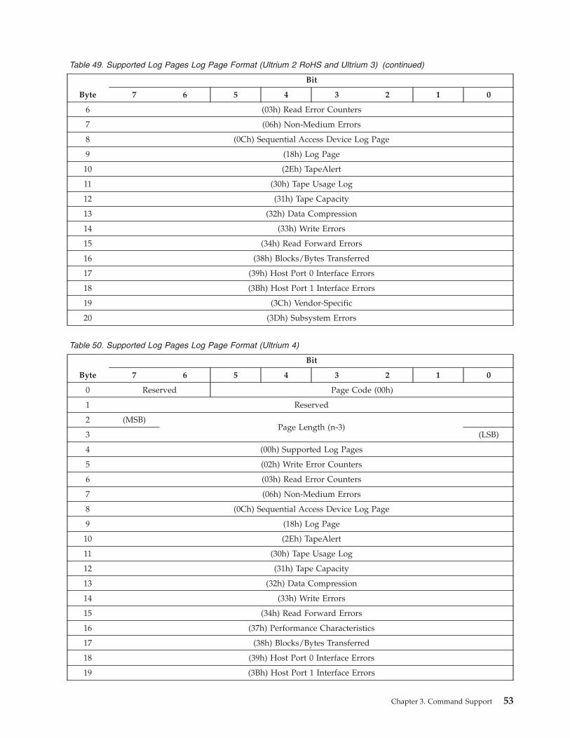
Table 49. Supported Log Pages Log Page Format (Ultrium 2 RoHS and Ultrium 3) (continued)
Byte
Bit
7 6 5 4 3 2 1 0
6 (03h) Read Error Counters
7 (06h) Non-Medium Errors
8 (0Ch) Sequential Access Device Log Page
9 (18h) Log Page
10 (2Eh) TapeAlert
11 (30h) Tape Usage Log
12 (31h) Tape Capacity
13 (32h) Data Compression
14 (33h) Write Errors
15 (34h) Read Forward Errors
16 (38h) Blocks/Bytes Transferred
17 (39h) Host Port 0 Interface Errors
18 (3Bh) Host Port 1 Interface Errors
19 (3Ch) Vendor-Specific
20 (3Dh) Subsystem Errors
Table 50. Supported Log Pages Log Page Format (Ultrium 4)
Byte
Bit
7 6 5 4 3 2 1 0
0 Reserved Page Code (00h)
1 Reserved
2 (MSB)
Page Length (n-3)
3 (LSB)
4 (00h) Supported Log Pages
5 (02h) Write Error Counters
6 (03h) Read Error Counters
7 (06h) Non-Medium Errors
8 (0Ch) Sequential Access Device Log Page
9 (18h) Log Page
10 (2Eh) TapeAlert
11 (30h) Tape Usage Log
12 (31h) Tape Capacity
13 (32h) Data Compression
14 (33h) Write Errors
15 (34h) Read Forward Errors
16 (37h) Performance Characteristics
17 (38h) Blocks/Bytes Transferred
18 (39h) Host Port 0 Interface Errors
19 (3Bh) Host Port 1 Interface Errors
Chapter 3. Command Support 53

Table 50. Supported Log Pages Log Page Format (Ultrium 4) (continued)
Byte
Bit
7 6 5 4 3 2 1 0
20 (3Ch) Vendor-Specific
21 (3Dh) Subsystem Errors
This data can be neither reset nor written.
54 IBM TotalStorage LTO Ultrium Tape Drive: SCSI Reference
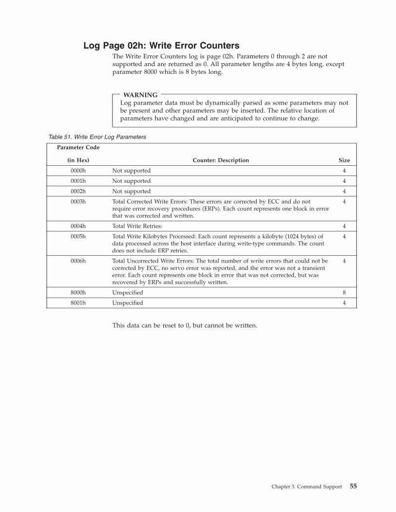
Log Page 02h: Write Error Counters
The Write Error Counters log is page 02h. Parameters 0 through 2 are not
supported and are returned as 0. All parameter lengths are 4 bytes long, except
parameter 8000 which is 8 bytes long.
WARNING
Log parameter data must be dynamically parsed as some parameters may not
be present and other parameters may be inserted. The relative location of
parameters have changed and are anticipated to continue to change.
Table 51. Write Error Log Parameters
Parameter Code
(in Hex) Counter: Description Size
0000h Not supported 4
0001h Not supported 4
0002h Not supported 4
0003h Total Corrected Write Errors: These errors are corrected by ECC and do not
require error recovery procedures (ERPs). Each count represents one block in error
that was corrected and written.
4
0004h Total Write Retries: 4
0005h Total Write Kilobytes Processed: Each count represents a kilobyte (1024 bytes) of
data processed across the host interface during write-type commands. The count
does not include ERP retries.
4
0006h Total Uncorrected Write Errors: The total number of write errors that could not be
corrected by ECC, no servo error was reported, and the error was not a transient
error. Each count represents one block in error that was not corrected, but was
recovered by ERPs and successfully written.
4
8000h Unspecified 8
8001h Unspecified 4
This data can be reset to 0, but cannot be written.
Chapter 3. Command Support 55

Log Page 03h: Read Error Counters
The Read Error Counters log is page 03h. Parameters 0 through 2 are not
supported and are returned as 0. All parameter lengths are 4 bytes long, except
parameter 8000 which is 8 bytes long.
WARNING
Log parameter data must be dynamically parsed as some parameters may not
be present and other parameters may be inserted. The relative location of
parameters have changed and are anticipated to continue to change.
The supported fields are listed in Table 52.
Table 52. Read Error Log Parameters
Parameter Code
(in Hex) Counter: Description Size
0000h Not supported 4
0001h Not supported 4
0002h Not supported 4
0003h
Total Corrective Read Errors:
These are errors that are corrected by ECC and do not require error recovery
procedures (ERPs). Each count represents one block in error that was corrected
and read.
4
0004h Total Read Retries: 4
0005h
Total Read Kilobytes Processed: Each count represents a kilobyte (1024 bytes)
processed across the host interface during read-type commands. The count
does not include ERP retries.
4
0006h
Total Uncorrected Read Errors: The total number of read errors that could not
be corrected by ECC, no servo error was reported, and the error was not a
transient error. Each count represents one block in error that was not corrected,
but was recovered by ERPs and successfully read.
4
8000h Unspecified 8
This data can be reset to 0, but not written.
56 IBM TotalStorage LTO Ultrium Tape Drive: SCSI Reference
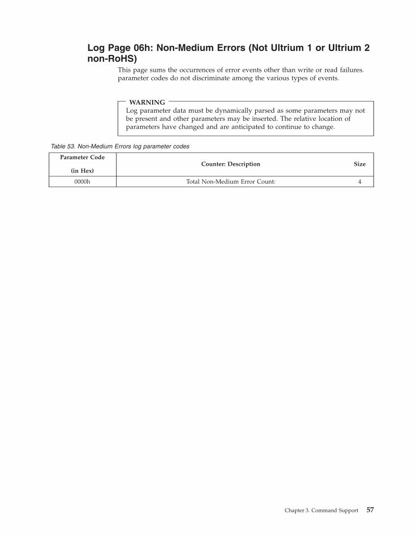
Log Page 06h: Non-Medium Errors (Not Ultrium 1 or Ultrium 2
non-RoHS)
This page sums the occurrences of error events other than write or read failures.
parameter codes do not discriminate among the various types of events.
WARNING
Log parameter data must be dynamically parsed as some parameters may not
be present and other parameters may be inserted. The relative location of
parameters have changed and are anticipated to continue to change.
Table 53. Non-Medium Errors log parameter codes
Parameter Code
(in Hex)
Counter: Description Size
0000h Total Non-Medium Error Count: 4
Chapter 3. Command Support 57
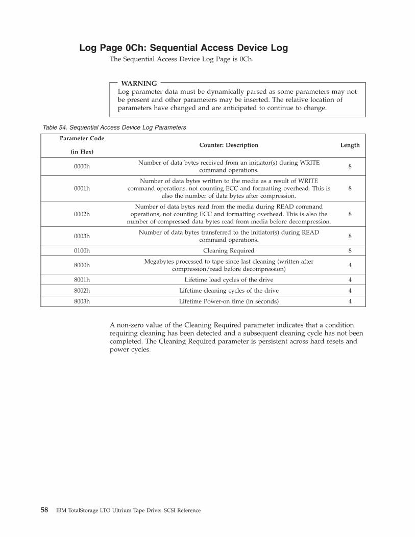
Log Page 0Ch: Sequential Access Device Log
The Sequential Access Device Log Page is 0Ch.
WARNING
Log parameter data must be dynamically parsed as some parameters may not
be present and other parameters may be inserted. The relative location of
parameters have changed and are anticipated to continue to change.
Table 54. Sequential Access Device Log Parameters
Parameter Code
(in Hex)
Counter: Description Length
0000h
Number of data bytes received from an initiator(s) during WRITE
command operations.
8
0001h
Number of data bytes written to the media as a result of WRITE
command operations, not counting ECC and formatting overhead. This is
also the number of data bytes after compression.
8
0002h
Number of data bytes read from the media during READ command
operations, not counting ECC and formatting overhead. This is also the
number of compressed data bytes read from media before decompression.
8
0003h
Number of data bytes transferred to the initiator(s) during READ
command operations.
8
0100h Cleaning Required 8
8000h
Megabytes processed to tape since last cleaning (written after
compression/read before decompression)
4
8001h Lifetime load cycles of the drive 4
8002h Lifetime cleaning cycles of the drive 4
8003h Lifetime Power-on time (in seconds) 4
A non-zero value of the Cleaning Required parameter indicates that a condition
requiring cleaning has been detected and a subsequent cleaning cycle has not been
completed. The Cleaning Required parameter is persistent across hard resets and
power cycles.
58 IBM TotalStorage LTO Ultrium Tape Drive: SCSI Reference
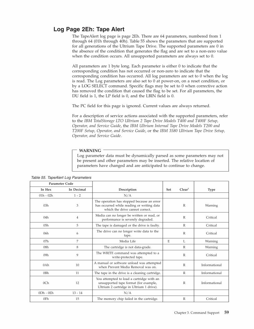
Log Page 2Eh: Tape Alert
The TapeAlert log page is page 2Eh. There are 64 parameters, numbered from 1
through 64 (01h through 40h). Table 55 shows the parameters that are supported
for all generations of the Ultrium Tape Drive. The supported parameters are 0 in
the absence of the condition that generates the flag and are set to a non-zero value
when the condition occurs. All unsupported parameters are always set to 0.
All parameters are 1 byte long. Each parameter is either 0 to indicate that the
corresponding condition has not occurred or non-zero to indicate that the
corresponding condition has occurred. All log parameters are set to 0 when the log
is read. The Log parameters are also set to 0 at power-on, on a reset condition, or
by a LOG SELECT command. Specific flags may be set to 0 when corrective action
has removed the condition that caused the flag to be set. For all parameters, the
DU field is 1, the LP field is 0, and the LBIN field is 0.
The PC field for this page is ignored. Current values are always returned.
For a description of service actions associated with the supported parameters, refer
to the IBM TotalStorage LTO Ultrium 2 Tape Drive Models T400 and T400F Setup,
Operator, and Service Guide, the IBM Ultrium Internal Tape Drive Models T200 and
T200F Setup, Operator, and Service Guide, or the IBM 3580 Ultrium Tape Drive Setup,
Operator, and Service Guide.
WARNING
Log parameter data must be dynamically parsed as some parameters may not
be present and other parameters may be inserted. The relative location of
parameters have changed and are anticipated to continue to change.
Table 55. TapeAlert Log Parameters
Parameter Code
In Hex In Decimal Description Set Clear1 Type
01h - 02h 1 - 2 N/A
03h 3
The operation has stopped because an error
has occurred while reading or writing data
which the drive cannot correct.
R Warning
04h 4
Media can no longer be written or read, or
performance is severely degraded.
R Critical
05h 5 The tape is damaged or the drive is faulty. R Critical
06h 6
The drive can no longer write data to the
tape.
R Critical
07h 7 Media Life E L Warning
08h 8 The cartridge is not data-grade. R Warning
09h 9
The WRITE command was attempted to a
write-protected tape.
R Critical
0Ah 10
A manual or software unload was attempted
when Prevent Media Removal was on.
R Informational
0Bh 11 The tape in the drive is a cleaning cartridge. R Informational
0Ch 12
You attempted to load a cartridge with an
unsupported tape format (for example,
Ultrium 2 cartridge in Ultrium 1 drive).
R Informational
0Dh - 0Eh 13 - 14 N/A
0Fh 15 The memory chip failed in the cartridge. R Critical
Chapter 3. Command Support 59
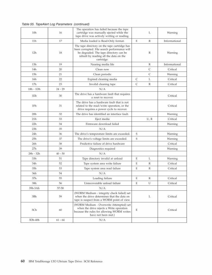
Table 55. TapeAlert Log Parameters (continued)
10h 16
The operation has failed because the tape
cartridge was manually ejected while the
tape drive was actively writing or reading.
L Warning
11h 17 Media loaded is Read-Only format. E R Informational
12h 18
The tape directory on the tape cartridge has
been corrupted. File search performance will
be degraded. The tape directory can be
rebuilt by reading all the data on the
cartridge.
R Warning
13h 19 Nearing media life R Informational
14h 20 Clean now C Critical
15h 21 Clean periodic C Warning
16h 22 Expired cleaning media C L Critical
17h 23 Invalid cleaning tape C R Critical
18h - 1Dh 24 - 29 N/A
1Eh 30
The drive has a hardware fault that requires
a reset to recover.
Critical
1Fh 31
The drive has a hardware fault that is not
related to the read/write operation, or the
drive requires a power cycle to recover.
Critical
20h 32 The drive has identified an interface fault. Warning
21h 33 Eject media U, R Critical
22h 34 Firmware download failed Warning
23h 35 N/A
24h 36 The drive’s temperature limits are exceeded. S Warning
25h 37 The drive’s voltage limits are exceeded. S Warning
26h 38 Predictive failure of drive hardware Critical
27h 39 Diagnostics required Warning
28h - 32h 40 - 50 N/A
33h 51 Tape directory invalid at unload E L Warning
34h 52 Tape system area write failure E R Critical
35h 53 Tape system area read failure E R Critical
36h 54 N/A
37h 55 Loading failure E R Critical
38h 56 Unrecoverable unload failure E U Critical
39h-3Ah 57-58 N/A
3Bh 59
(WORM Medium - integrity check failed) set
when the drive determines that the data on
tape is suspect from a WORM point of view.
L Critical
3Ch 60
(WORM Medium - Overwrite Attempted) set
when the drive rejects a Write operation
because the rules for allowing WORM writes
have not been met.)
E Critical
3Dh-40h 61 - 64 N/A
60 IBM TotalStorage LTO Ultrium Tape Drive: SCSI Reference
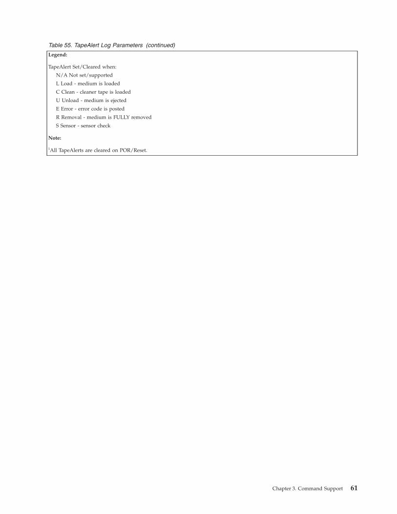
Table 55. TapeAlert Log Parameters (continued)
Legend:
TapeAlert Set/Cleared when:
N/A Not set/supported
L Load - medium is loaded
C Clean - cleaner tape is loaded
U Unload - medium is ejected
E Error - error code is posted
R Removal - medium is FULLY removed
S Sensor - sensor check
Note:
1All TapeAlerts are cleared on POR/Reset.
Chapter 3. Command Support 61
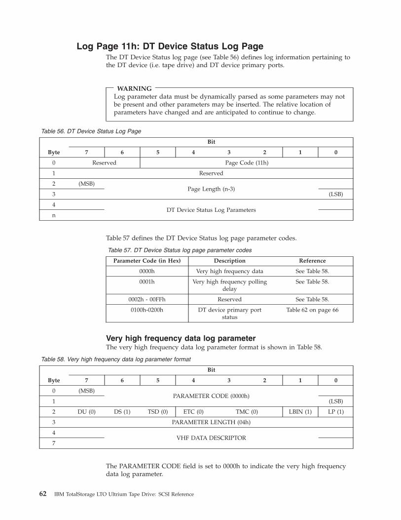
Log Page 11h: DT Device Status Log Page
The DT Device Status log page (see Table 56) defines log information pertaining to
the DT device (i.e. tape drive) and DT device primary ports.
WARNING
Log parameter data must be dynamically parsed as some parameters may not
be present and other parameters may be inserted. The relative location of
parameters have changed and are anticipated to continue to change.
Table 56. DT Device Status Log Page
Byte
Bit
7 6 5 4 3 2 1 0
0 Reserved Page Code (11h)
1 Reserved
2 (MSB)
Page Length (n-3)
3 (LSB)
4
DT Device Status Log Parameters
n
Table 57 defines the DT Device Status log page parameter codes.
Table 57. DT Device Status log page parameter codes
Parameter Code (in Hex) Description Reference
0000h Very high frequency data See Table 58.
0001h Very high frequency polling
delay
See Table 58.
0002h - 00FFh Reserved See Table 58.
0100h-0200h DT device primary port
status
Table 62 on page 66
Very high frequency data log parameter
The very high frequency data log parameter format is shown in Table 58.
Table 58. Very high frequency data log parameter format
Byte
Bit
7 6 5 4 3 2 1 0
0 (MSB)
PARAMETER CODE (0000h)
1 (LSB)
2 DU (0) DS (1) TSD (0) ETC (0) TMC (0) LBIN (1) LP (1)
3 PARAMETER LENGTH (04h)
4
VHF DATA DESCRIPTOR
7
The PARAMETER CODE field is set to 0000h to indicate the very high frequency
data log parameter.
62 IBM TotalStorage LTO Ultrium Tape Drive: SCSI Reference

The PARAMETER LENGTH field is set to 04h to allow transfer of the complete
parameter.
The VHF DATA DESCRIPTOR field is defined in Table 59. Returned data shall
reflect the last known values since the DT device initialized.
Table 59. VHF DATA DESCRIPTOR field
Byte
Bit
7 6 5 4 3 2 1 0
4 PAMR HIU MACC CMPR WRTP CQRST CRQRD DINIT
5
INXTN Rsvd RAA® MPRSNT Rsvd MSTD
MTHRD
MOUNTED
MTHRD
MOUNTED
6 DT DEVICE ACTIVITY
7 VS Reserved RRQST INTFC TAFC
Note: In addition to reliance on indication of initialization completion, reliance on
returned values should also take into consideration conditions indicated by
changes in Tape Alert flag status, and process those first as needed.
A DT device initialized (DINIT) bit set to one indicates that the DT device is able
to return valid very high frequency data. A DINIT bit set to zero indicates DT
device initialization is required or incomplete. The DINIT bit should be set to one
before relying on any other bits in the very high frequency data log parameter.
A cleaning required (CRQRD) bit set to one indicates that a head cleaning
operation is required before a data medium is able to reach load state (i) (see
ADC-2), and that normal operation may not be possible if the head cleaning
operation is not performed. A CRQRD bit set to zero indicates that urgent cleaning
is not required. The CRQRD bit shall take priority over the CRQST bit. It shall not
be considered an error for the CRQRD bit and the CRQST bit to both be set to one.
A cleaning requested (CRQST) bit set to one indicates that the DT device has
requested a head cleaning. A CRQST bit set to zero indicates that no cleaning is
requested.
A write protect (WRTP) bit set to one indicates that any currently present medium
is physically write protected. A WRTP bit set to zero indicates that any currently
present medium is not physically write protected. The WRTP bit is only valid if the
MPRSNT bit is set to one. The WRTP bit should be set to zero if the MPRSNT bit
is set to zero.
Note: Physically write protected refers to any mechanism used within the medium
shell itself to write protect the medium (for example, sliding windows or
tabs) and not logical states of write protection caused by commands to the
DT device.
A compress (CMPR) bit set to one indicates that the DT device currently has data
compression enabled. A CMPR bit set to zero indicates that compression is not
enabled.
A medium auxiliary memory accessible (MACC) bit set to one indicates that the
medium is located at a position where the Medium Auxiliary Memory (MAM) is
accessible. A MACC bit set to zero indicates that the MAM is not accessible. If the
MACC bit is set to one, the ADC device server shall also support commands to
Chapter 3. Command Support 63
access the MAM. If the MACC bit is supported the MACC bit should only be set
to one if the MPRSNT bit is set to one. The MACC bit is only applicable for drives
and media that support MAM.
The host initiated unload (HIU) bit is set to one when the drive reaches any one of
the unload states (e) - (h) (see ADC-2r07e, Clause 4.4.2), due to the RMC device
server receiving a LOAD UNLOAD command (see SSC-2) with the LOAD bit set
to zero. The HIU bit is set to zero when the drive transitions to any state in table 2
or table 4 of ADC-2r07e other than unload states (e) - (h) in table 4 of ADC-2r07e.
The HIU bit may be set to zero following a logical unit reset of the RMC or ADC
device servers.
The prevent/allow medium removal (PAMR) bit is set to one when removal of the
medium in the DT device is prevented as the result of the RMC device server
processing a PREVENT/ALLOW MEDIUM REMOVAL command (see SPC-3 or the
relevant command set standard).
The PAMR bit is set to zero when removal of the medium in the DT device is
allowed as defined by the PREVENT/ALLOW MEDIUM REMOVAL command.
A MOUNTED bit set to one indicates that the DT device is in load state (i) (see
ADC-2). The MOUNTED bit set to one may correspond to the RMC device server
being able to respond to a TEST UNIT READY command with a status of GOOD,
however when a cleaning or microcode image medium is loaded the RMC device
server may respond to a TEST UNIT READY command with a CHECK
CONDITON with the sense key set to NOT READY. A MOUNTED bit set to zero
indicates that the DT device is not in load state (i).
A medium threaded (MTHRD) bit set to one indicates that the medium has been
threaded by the DT device, such that tape motion operations are possible. A
MTHRD bit set to zero indicates that the medium has not been threaded.
Note: The value of the MTHRD bit may or may not correspond to the DT device
responding with a status of GOOD to a TEST UNIT READY command, as
additional processing may be required by the DT device after threading
before the logical unit becomes ready.
A medium seated (MSTD) bit set to one indicates that the medium is mechanically
seated within the loading mechanism (i.e., the physical loading process has
completed). A MSTD bit set to zero indicates that the medium is not seated, and
that further mechanical motion remains in order to complete the loading process,
exclusive of tape threading.
A medium present (MPRSNT) bit set to one indicates that the DT device detects
the presence of a medium. A MPRSNT bit set to zero indicates that the DT device
does not detect a medium present.
A robotic access allowed (RAA) bit set to one indicates that the automation device
may move a medium to or from the DT device. A RAA bit set to zero indicates
that the automation device should not move a medium to or from the DT device.
The DT device should indicate that access is allowed by the robotics if a medium
may be successfully inserted into or removed from the DT device.
Note: The RAA bit is not intended to reflect the value of any PREVENT/ALLOW
MEDIUM REMOVAL command settings (see SPC-3), nor the ability of the
automation device to issue commands to the DT device.
64 IBM TotalStorage LTO Ultrium Tape Drive: SCSI Reference
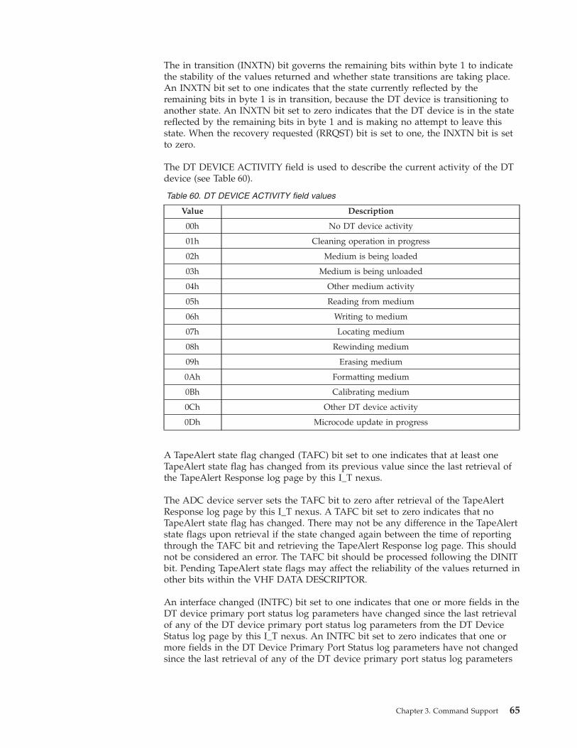
The in transition (INXTN) bit governs the remaining bits within byte 1 to indicate
the stability of the values returned and whether state transitions are taking place.
An INXTN bit set to one indicates that the state currently reflected by the
remaining bits in byte 1 is in transition, because the DT device is transitioning to
another state. An INXTN bit set to zero indicates that the DT device is in the state
reflected by the remaining bits in byte 1 and is making no attempt to leave this
state. When the recovery requested (RRQST) bit is set to one, the INXTN bit is set
to zero.
The DT DEVICE ACTIVITY field is used to describe the current activity of the DT
device (see Table 60).
Table 60. DT DEVICE ACTIVITY field values
Value Description
00h No DT device activity
01h Cleaning operation in progress
02h Medium is being loaded
03h Medium is being unloaded
04h Other medium activity
05h Reading from medium
06h Writing to medium
07h Locating medium
08h Rewinding medium
09h Erasing medium
0Ah Formatting medium
0Bh Calibrating medium
0Ch Other DT device activity
0Dh Microcode update in progress
A TapeAlert state flag changed (TAFC) bit set to one indicates that at least one
TapeAlert state flag has changed from its previous value since the last retrieval of
the TapeAlert Response log page by this I_T nexus.
The ADC device server sets the TAFC bit to zero after retrieval of the TapeAlert
Response log page by this I_T nexus. A TAFC bit set to zero indicates that no
TapeAlert state flag has changed. There may not be any difference in the TapeAlert
state flags upon retrieval if the state changed again between the time of reporting
through the TAFC bit and retrieving the TapeAlert Response log page. This should
not be considered an error. The TAFC bit should be processed following the DINIT
bit. Pending TapeAlert state flags may affect the reliability of the values returned in
other bits within the VHF DATA DESCRIPTOR.
An interface changed (INTFC) bit set to one indicates that one or more fields in the
DT device primary port status log parameters have changed since the last retrieval
of any of the DT device primary port status log parameters from the DT Device
Status log page by this I_T nexus. An INTFC bit set to zero indicates that one or
more fields in the DT Device Primary Port Status log parameters have not changed
since the last retrieval of any of the DT device primary port status log parameters
Chapter 3. Command Support 65
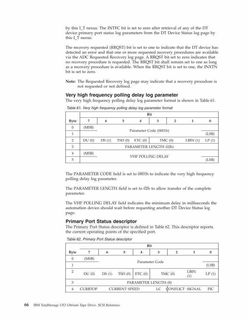
by this I_T nexus. The INTFC bit is set to zero after retrieval of any of the DT
device primary port status log parameters from the DT Device Status log page by
this I_T nexus.
The recovery requested (RRQST) bit is set to one to indicate that the DT device has
detected an error and that one or more requested recovery procedures are available
via the ADC Requested Recovery log page. A RRQST bit set to zero indicates that
no recovery procedure is requested. The RRQST bit shall remain set to one as long
as a recovery procedure is available. When the RRQST bit is set to one, the INXTN
bit is set to zero.
Note: The Requested Recovery log page may indicate that a recovery procedure is
not requested or not defined.
Very high frequency polling delay log parameter
The very high frequency polling delay log parameter format is shown in Table 61.
Table 61. Very high frequency polling delay log parameter format
Byte
Bit
7 6 5 4 3 2 1 0
0 (MSB)
Parameter Code (0001h)
1 (LSB)
2 DU (0) DS (1) TSD (0) ETC (0) TMC (0) LBIN (1) LP (1)
3 PARAMETER LENGTH (02h)
4 (MSB)
VHF POLLING DELAY
5 (LSB)
The PARAMETER CODE field is set to 0001h to indicate the very high frequency
polling delay log parameter.
The PARAMETER LENGTH field is set to 02h to allow transfer of the complete
parameter.
The VHF POLLING DELAY field indicates the minimum delay in milliseconds the
automation device should wait before requesting another DT Device Status log
page.
Primary Port Status descriptor
The Primary Port Status descriptor is defined in Table 62. This descriptor reports
the current operating points of the specified port.
Table 62. Primary Port Status descriptor
Byte
Bit
7 6 5 4 3 2 1 0
0 (MSB)
Parameter Code
1 (LSB)
2
DU (0) DS (1) TSD (0) ETC (0) TMC (0)
LBIN
(1)
LP (1)
3 PARAMETER LENGTH (8)
4 CURRTOP CURRENT SPEED LC CONFLICT SIGNAL PIC
66 IBM TotalStorage LTO Ultrium Tape Drive: SCSI Reference
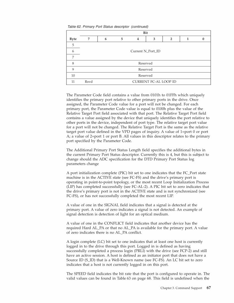
Table 62. Primary Port Status descriptor (continued)
Byte
Bit
7 6 5 4 3 2 1 0
5
Current N_Port_ID 6
7
8 Reserved
9 Reserved
10 Reserved
11 Rsvd CURRENT FC-AL LOOP ID
The Parameter Code field contains a value from 0101h to 01FFh which uniquely
identifies the primary port relative to other primary ports in the drive. Once
assigned, the Parameter Code value for a port will not be changed. For each
primary port, the Parameter Code value is equal to 0100h plus the value of the
Relative Target Port field associated with that port. The Relative Target Port field
contains a value assigned by the device that uniquely identifies the port relative to
other ports in the device, independent of port type. The relative target port value
for a port will not be changed. The Relative Target Port is the same as the relative
target port value defined in the VPD pages of inquiry. A value of 1=port 0 or port
A; a value of 2=port 1 or port B. All values in this descriptor relates to the primary
port specified by the Parameter Code.
The Additional Primary Port Status Length field specifies the additional bytes in
the current Primary Port Status descriptor. Currently this is 4, but this is subject to
change should the ADC specification for the DTD Primary Port Status log
parameters change
A port initialization complete (PIC) bit set to one indicates that the FC_Port state
machine is in the ACTIVE state (see FC-FS) and the drive’s primary port is
operating in point-to-point topology, or the most recent Loop Initialization Process
(LIP) has completed successfully (see FC-AL-2). A PIC bit set to zero indicates that
the drive’s primary port is not in the ACTIVE state and is not synchronized (see
FC-FS), or has not successfully completed the most recent LIP.
A value of one in the SIGNAL field indicates that a signal is detected at the
primary port. A value of zero indicates a signal is not detected. An example of
signal detection is detection of light for an optical medium.
A value of one in the CONFLICT field indicates that another device has the
required Hard AL_PA or that no AL_PA is available for the primary port. A value
of zero indicates there is no AL_PA conflict.
A login complete (LC) bit set to one indicates that at least one host is currently
logged in to the drive through this port. Logged in is defined as having
successfully completed a process login (PRLI) with the drive (see FCP-2) and still
have an active session. A host is defined as an initiator port that does not have a
Source ID (S_ID) that is a Well-Known name (see FC-FS). An LC bit set to zero
indicates that a host is not currently logged in on this port.
The SPEED field indicates the bit rate that the port is configured to operate in. The
valid values can be found in Table 63 on page 68. This field is undefined when the
Chapter 3. Command Support 67
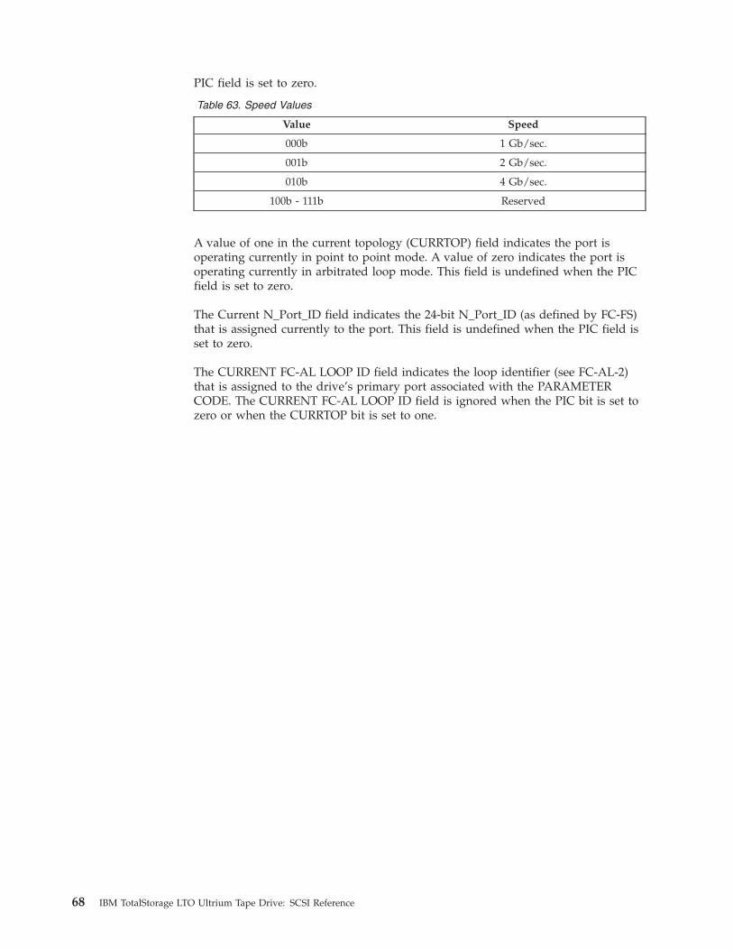
PIC field is set to zero.
Table 63. Speed Values
Value Speed
000b 1 Gb/sec.
001b 2 Gb/sec.
010b 4 Gb/sec.
100b - 111b Reserved
A value of one in the current topology (CURRTOP) field indicates the port is
operating currently in point to point mode. A value of zero indicates the port is
operating currently in arbitrated loop mode. This field is undefined when the PIC
field is set to zero.
The Current N_Port_ID field indicates the 24-bit N_Port_ID (as defined by FC-FS)
that is assigned currently to the port. This field is undefined when the PIC field is
set to zero.
The CURRENT FC-AL LOOP ID field indicates the loop identifier (see FC-AL-2)
that is assigned to the drive’s primary port associated with the PARAMETER
CODE. The CURRENT FC-AL LOOP ID field is ignored when the PIC bit is set to
zero or when the CURRTOP bit is set to one.
68 IBM TotalStorage LTO Ultrium Tape Drive: SCSI Reference
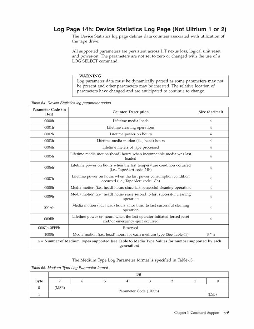
Log Page 14h: Device Statistics Log Page (Not Ultrium 1 or 2)
The Device Statistics log page defines data counters associated with utilization of
the tape drive.
All supported parameters are persistent across I_T nexus loss, logical unit reset
and power-on. The parameters are not set to zero or changed with the use of a
LOG SELECT command.
WARNING
Log parameter data must be dynamically parsed as some parameters may not
be present and other parameters may be inserted. The relative location of
parameters have changed and are anticipated to continue to change.
Table 64. Device Statistics log parameter codes
Parameter Code (in
Hex)
Counter: Description Size (decimal)
0000h Lifetime media loads 4
0001h Lifetime cleaning operations 4
0002h Lifetime power on hours 4
0003h Lifetime media motion (i.e., head) hours 4
0004h Lifetime meters of tape processed 4
0005h
Lifetime media motion (head) hours when incompatible media was last
loaded
4
0006h
Lifetime power on hours when the last temperature condition occurred
(i.e., TapeAlert code 24h)
4
0007h
Lifetime power on hours when the last power consumption condition
occurred (i.e., TapeAlert code 1Ch)
4
0008h Media motion (i.e., head) hours since last successful cleaning operation 4
0009h
Media motion (i.e., head) hours since second to last successful cleaning
operation
4
000Ah
Media motion (i.e., head) hours since third to last successful cleaning
operation
4
000Bh
Lifetime power on hours when the last operator initiated forced reset
and/or emergency eject occurred
4
000Ch-0FFFh Reserved
1000h Media motion (i.e., head) hours for each medium type (See Table 65) 8 * n
n = Number of Medium Types supported (see Table 65 Media Type Values for number supported by each
generation)
The Medium Type Log Parameter format is specified in Table 65.
Table 65. Medium Type Log Parameter format
Byte
Bit
7 6 5 4 3 2 1 0
0 (MSB)
Parameter Code (1000h)
1 (LSB)
Chapter 3. Command Support 69
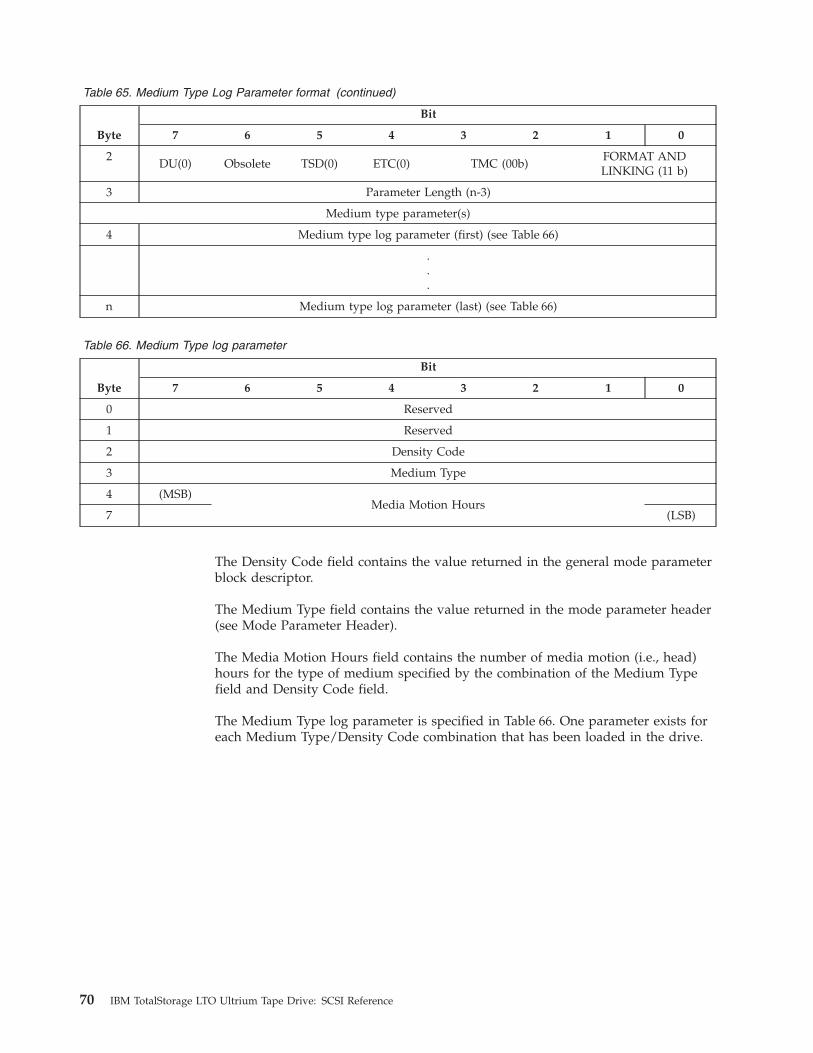
Table 65. Medium Type Log Parameter format (continued)
Byte
Bit
7 6 5 4 3 2 1 0
2
DU(0) Obsolete TSD(0) ETC(0) TMC (00b)
FORMAT AND
LINKING (11 b)
3 Parameter Length (n-3)
Medium type parameter(s)
4 Medium type log parameter (first) (see Table 66)
.
.
.
n Medium type log parameter (last) (see Table 66)
Table 66. Medium Type log parameter
Byte
Bit
7 6 5 4 3 2 1 0
0 Reserved
1 Reserved
2 Density Code
3 Medium Type
4 (MSB)
Media Motion Hours
7 (LSB)
The Density Code field contains the value returned in the general mode parameter
block descriptor.
The Medium Type field contains the value returned in the mode parameter header
(see Mode Parameter Header).
The Media Motion Hours field contains the number of media motion (i.e., head)
hours for the type of medium specified by the combination of the Medium Type
field and Density Code field.
The Medium Type log parameter is specified in Table 66. One parameter exists for
each Medium Type/Density Code combination that has been loaded in the drive.
70 IBM TotalStorage LTO Ultrium Tape Drive: SCSI Reference

Log Page 16h: Tape Diagnostic Data Log Page (Not Ultrium 1
or 2)
The Tape Diagnostic Data log page (see Table 67) provides for a number of
error-event records using the list parameter format. Each error-event record
contains diagnostic information for a single error type encountered by the device
including data counters associated with the error event, sense data, operation
code/service action and medium type with associated media motion hours, etc.
The Tape Diagnostic Data log page may be used to aid in field analysis and repair.
The Tape Diagnostic Data log page only includes parameter entries for commands
that terminated with a CHECK CONDITION status having the sense key set to
MEDIUM ERROR, HARDWARE ERROR or ABORTED COMMAND.
The parameter code value associated with an error-event indicates the relative time
at which a command terminated with a CHECK CONDITION status. A lower
parameter code indicates that the command terminated with a CHECK
CONDITION status at a more recent time. The parameter code values returned is
numbered consecutively from 0000h (i.e., the most recent) up to n, where n is the
number of current parameter entries.
In each parameter (see Table 68 on page 72) if the REPEAT bit is set to zero, then
the parameter represents only one event. If the REPEAT bit is set to one, then the
parameter represents more than one consecutive events that had identical values
for the MEDIUM ID NUMBER field, SENSE KEY field, ADDITIONAL SENSE
CODE field and ADDITIONAL SENSE CODE QUALIFIER field in the parameter.
If the REPEAT bit is set to one in the parameter, then other fields in the parameter
is set to the values when the first of the consecutive events that had the identical
values for the MEDIUM ID NUMBER field, SENSE KEY field, ADDITIONAL
SENSE CODE field and ADDITIONAL SENSE CODE QUALIFIER field occurred.
All parameter codes are persistent across I_T nexus losses, logical unit resets, and
power-on. The parameter entries are not set to zero or changed with the use of a
LOG SELECT command.
WARNING
Log parameter data must be dynamically parsed as some parameters may not
be present and other parameters may be inserted. The relative location of
parameters have changed and are anticipated to continue to change.
Table 67. Tape Diagnostic Data log page
Byte
Bit
7 6 5 4 3 2 1 0
0 DS SPF(0) Page Code (16h)
1 Subpage Code (00h)
2 (MSB)
Page Length (n-3)
3 (LSB)
Tape Diagnostic Data log parameter(s)
4 Tape Diagnostic Data log parameter (first)
n Tape Diagnostic Data log parameter (last)
Chapter 3. Command Support 71
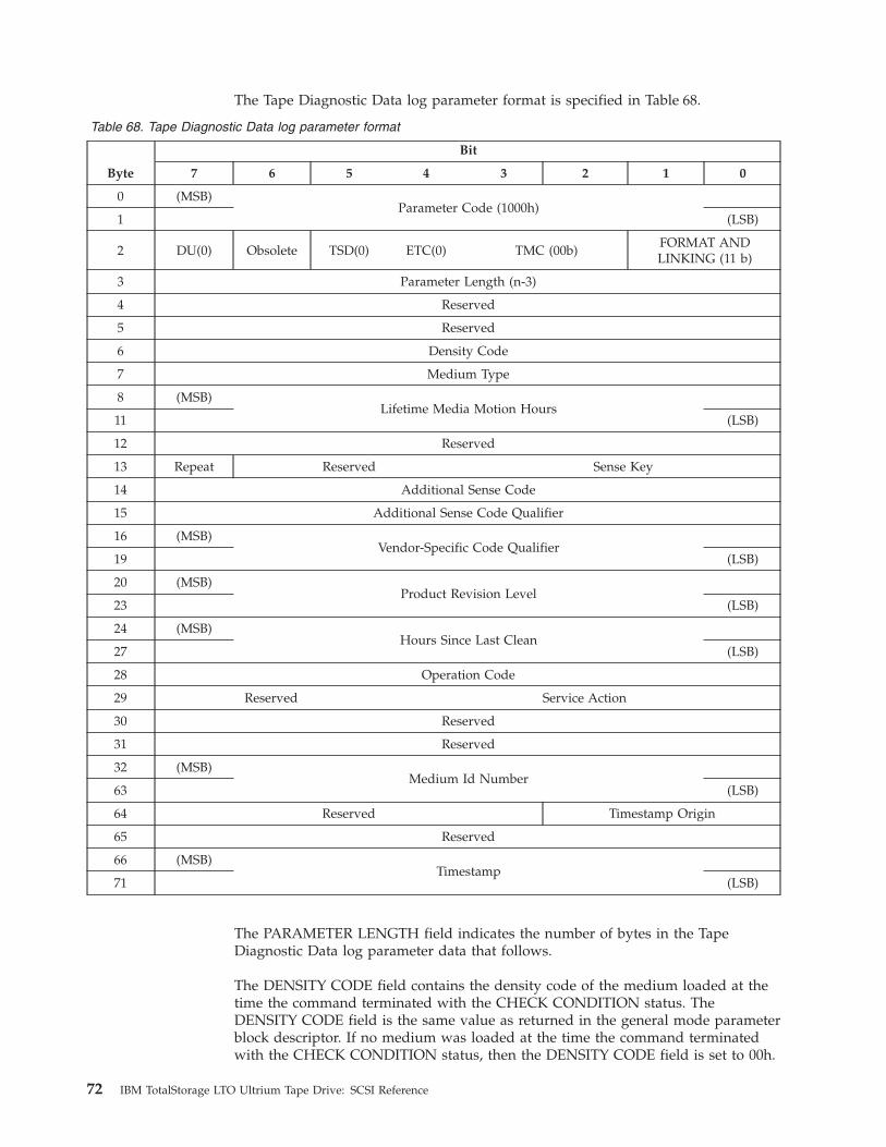
The Tape Diagnostic Data log parameter format is specified in Table 68.
Table 68. Tape Diagnostic Data log parameter format
Byte
Bit
7 6 5 4 3 2 1 0
0 (MSB)
Parameter Code (1000h)
1 (LSB)
2 DU(0) Obsolete TSD(0) ETC(0) TMC (00b)
FORMAT AND
LINKING (11 b)
3 Parameter Length (n-3)
4 Reserved
5 Reserved
6 Density Code
7 Medium Type
8 (MSB)
Lifetime Media Motion Hours
11 (LSB)
12 Reserved
13 Repeat Reserved Sense Key
14 Additional Sense Code
15 Additional Sense Code Qualifier
16 (MSB)
Vendor-Specific Code Qualifier
19 (LSB)
20 (MSB)
Product Revision Level
23 (LSB)
24 (MSB)
Hours Since Last Clean
27 (LSB)
28 Operation Code
29 Reserved Service Action
30 Reserved
31 Reserved
32 (MSB)
Medium Id Number
63 (LSB)
64 Reserved Timestamp Origin
65 Reserved
66 (MSB)
Timestamp
71 (LSB)
The PARAMETER LENGTH field indicates the number of bytes in the Tape
Diagnostic Data log parameter data that follows.
The DENSITY CODE field contains the density code of the medium loaded at the
time the command terminated with the CHECK CONDITION status. The
DENSITY CODE field is the same value as returned in the general mode parameter
block descriptor. If no medium was loaded at the time the command terminated
with the CHECK CONDITION status, then the DENSITY CODE field is set to 00h.
72 IBM TotalStorage LTO Ultrium Tape Drive: SCSI Reference
The MEDIUM TYPE field contains the type of medium loaded at the time the
command terminated with the CHECK CONDITION status. The MEDIUM TYPE
field is the same value as returned in the mode parameter header. If no medium
was loaded at the time the command terminated with the CHECK CONDITION
status, then the MEDIUM TYPE field is set to 00h.
The LIFETIME MEDIA MOTION HOURS field contains the number of media
motion (head) hours at the time the command terminated with the CHECK
CONDITION status. The LIFETIME MEDIA MOTION HOURS field is equivalent
to the value contained in the Device Statistics log page with a parameter code
value of 0003h at the time the command terminated with the CHECK CONDITION
status.
The REPEAT bit set to one indicates this parameter represents more than one
consecutive events that had identical values for the MEDIUM ID NUMBER field,
SENSE KEY field, ADDITIONAL SENSE CODE field, and ADDITIONAL SENSE
CODE QUALIFIER field. The REPEAT bit set to zero indicates this parameter
represents a single event.
The SENSE KEY field, ADDITIONAL SENSE CODE field, and ADDITIONAL
SENSE CODE QUALIFIER field contain the sense key and additional sense code
values of the command that terminated with the CHECK CONDITION status.
The VENDOR-SPECIFIC CODE QUALIFIER field contains the Last Error FSC and
Last Error Flag Data (i.e. bytes 65-68 of Sense Data) generated for the command
that terminated with the CHECK CONDITION status.
The PRODUCT REVISION LEVEL field contains the product revision level at the
time the command terminated with the CHECK CONDITION status.
The HOURS SINCE LAST CLEAN field contains the time in media motion (i.e.,
head) hours since the last successful cleaning at the time the command terminated
with the CHECK CONDITION status. The HOURS SINCE LAST CLEAN field is
equivalent to the value contained in the Device Statistics log page with a
parameter code of 0008h at the time the command terminated with the CHECK
CONDITION status.
The OPERATION CODE field and SERVICE ACTION field if applicable contain
the operation code and service action of the command that terminated with the
CHECK CONDITION status.
If medium was present at the time the command terminated with the CHECK
CONDITION status, then the MEDIUM ID NUMBER field contains (in prioritized
order):
1. the BARCODE field value contained in the medium auxiliary memory;
2. the MEDIUM SERIAL NUMBER field value contained in the medium auxiliary
memory; or
3. the VOLUME IDENTIFIER field value contained in the medium auxiliary
memory.
The TIMESTAMP ORIGIN field and TIMESTAMP field contain the timestamp
origin and timestamp maintained by the tape drive at the time the command
terminated with the CHECK CONDITION status. If a timestamp is not supported
by the device server, the TIMESTAMP ORIGIN and TIMESTAMP fields is set to
zero.
Chapter 3. Command Support 73
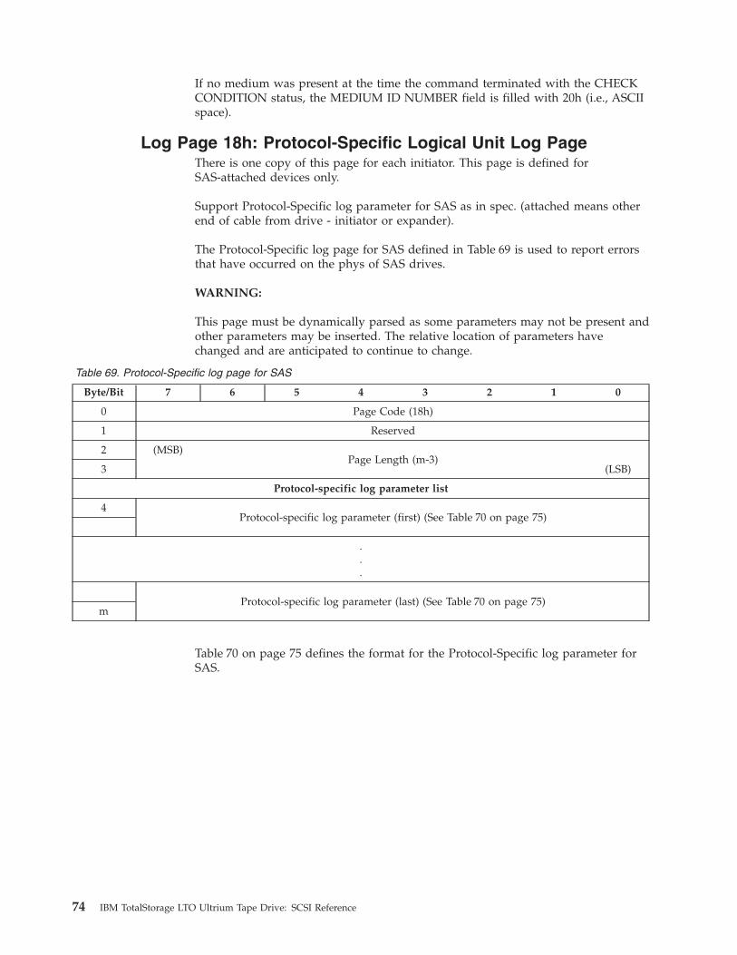
If no medium was present at the time the command terminated with the CHECK
CONDITION status, the MEDIUM ID NUMBER field is filled with 20h (i.e., ASCII
space).
Log Page 18h: Protocol-Specific Logical Unit Log Page
There is one copy of this page for each initiator. This page is defined for
SAS-attached devices only.
Support Protocol-Specific log parameter for SAS as in spec. (attached means other
end of cable from drive - initiator or expander).
The Protocol-Specific log page for SAS defined in Table 69 is used to report errors
that have occurred on the phys of SAS drives.
WARNING:
This page must be dynamically parsed as some parameters may not be present and
other parameters may be inserted. The relative location of parameters have
changed and are anticipated to continue to change.
Table 69. Protocol-Specific log page for SAS
Byte/Bit 7 6 5 4 3 2 1 0
0 Page Code (18h)
1 Reserved
2 (MSB)
Page Length (m-3)
3 (LSB)
Protocol-specific log parameter list
4
Protocol-specific log parameter (first) (See Table 70 on page 75)
.
.
.
Protocol-specific log parameter (last) (See Table 70 on page 75)
m
Table 70 on page 75 defines the format for the Protocol-Specific log parameter for
SAS.
74 IBM TotalStorage LTO Ultrium Tape Drive: SCSI Reference
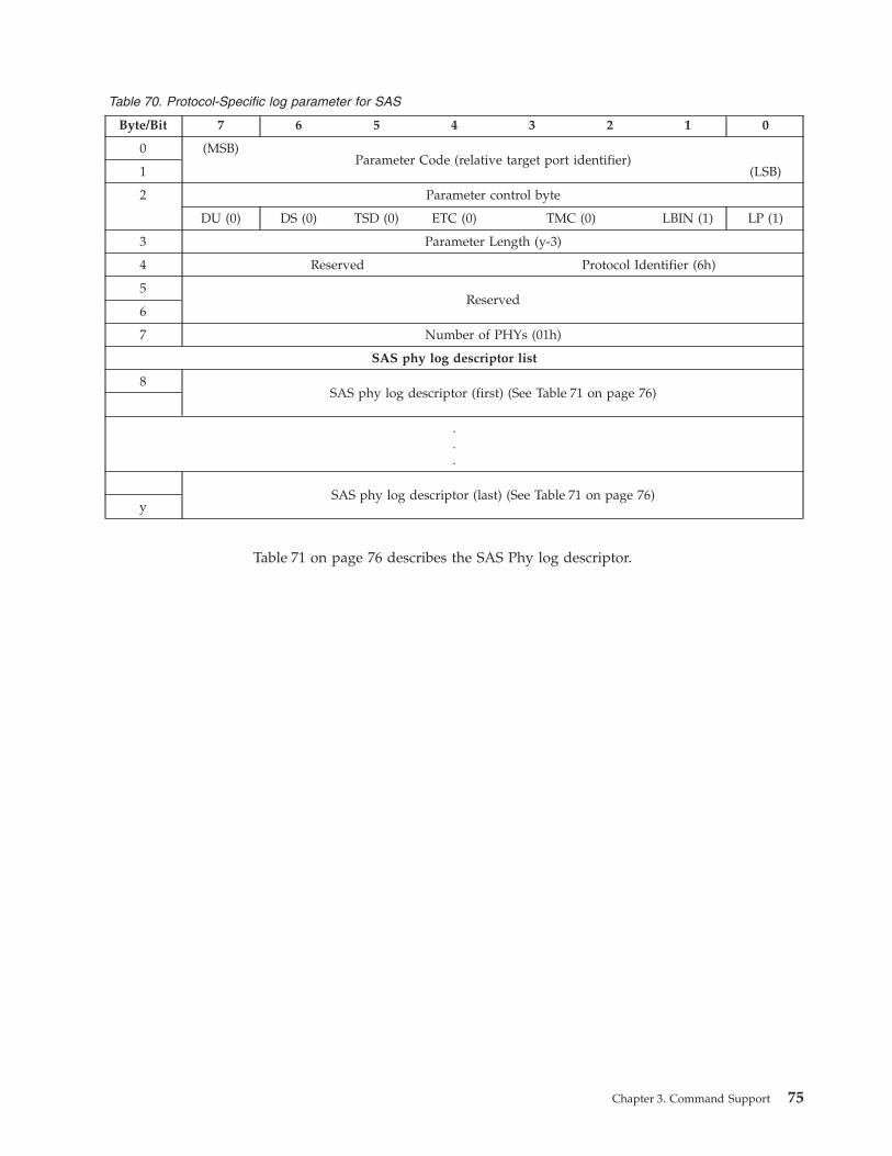
Table 70. Protocol-Specific log parameter for SAS
Byte/Bit 7 6 5 4 3 2 1 0
0 (MSB)
Parameter Code (relative target port identifier)
1 (LSB)
2 Parameter control byte
DU (0) DS (0) TSD (0) ETC (0) TMC (0) LBIN (1) LP (1)
3 Parameter Length (y-3)
4 Reserved Protocol Identifier (6h)
5
Reserved
6
7 Number of PHYs (01h)
SAS phy log descriptor list
8
SAS phy log descriptor (first) (See Table 71 on page 76)
.
.
.
SAS phy log descriptor (last) (See Table 71 on page 76)
y
Table 71 on page 76 describes the SAS Phy log descriptor.
Chapter 3. Command Support 75

Table 71. SAS Phy log descriptor
Byte/Bit 7 6 5 4 3 2 1 0
0 Reserved
1 Phy Identifier
2
Reserved
3
4 Rsvd Attached Device Type Reserved
5 Reserved Negotiated Physical Link Rate
6
Reserved
Attached
SSP
Initiator
Attached
STP
Initiator
Attached
SMP
Initiator
Rsvd
7
Reserved
Attached
SSP
Target
Attached
STP
Target
Attached
SMP
Target
Rsvd
8
SAS Address
15
16
Attached SAS Address
23
24 Attached Phy Identifier
25
Reserved
31
32 MSB
Invalid Dword Count
35 LSB
36 MSB
Running Disparity Error Count
39 LSB
40 MSB
Loss Of Dword Synchronization
43 LSB
44 MSB
Phy Reset Problem
47 LSB
76 IBM TotalStorage LTO Ultrium Tape Drive: SCSI Reference
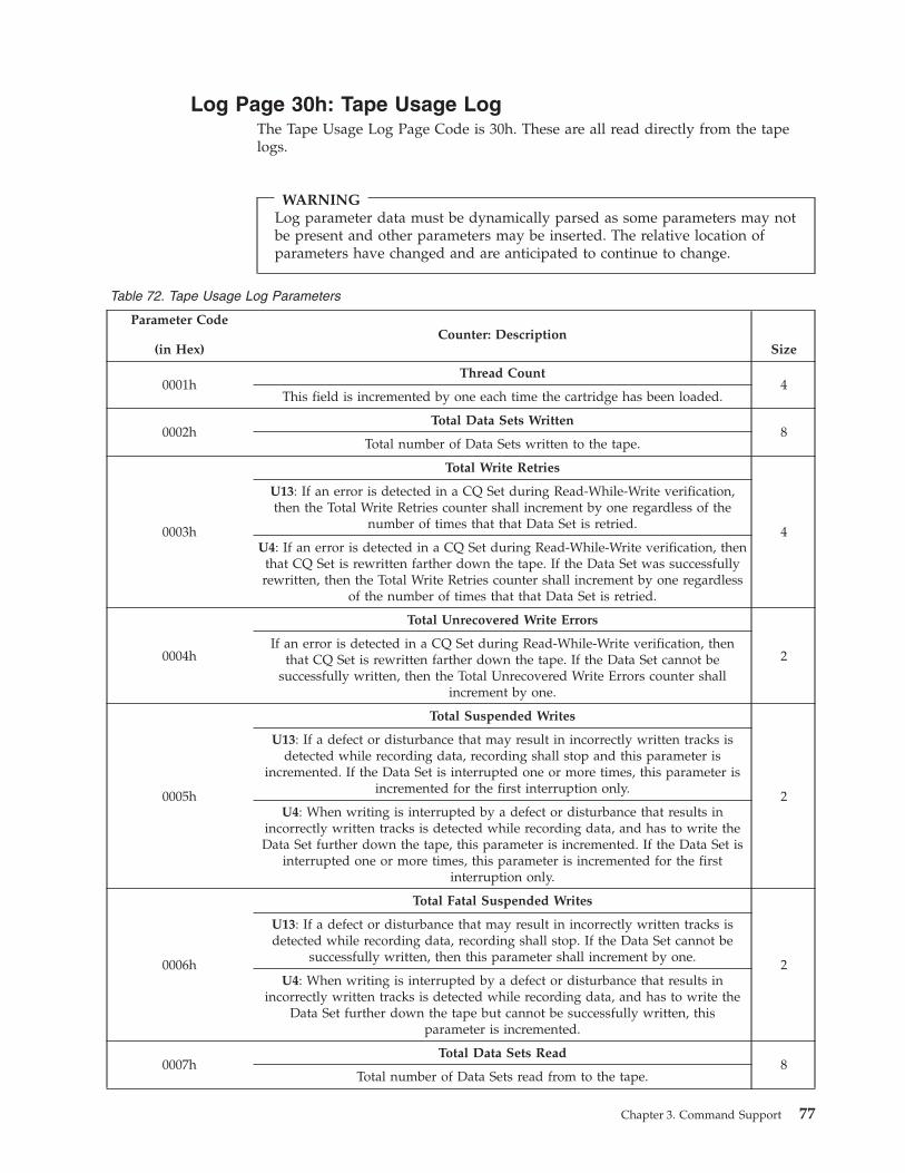
Log Page 30h: Tape Usage Log
The Tape Usage Log Page Code is 30h. These are all read directly from the tape
logs.
WARNING
Log parameter data must be dynamically parsed as some parameters may not
be present and other parameters may be inserted. The relative location of
parameters have changed and are anticipated to continue to change.
Table 72. Tape Usage Log Parameters
Parameter Code
(in Hex)
Counter: Description
Size
0001h
Thread Count
4
This field is incremented by one each time the cartridge has been loaded.
0002h
Total Data Sets Written
8
Total number of Data Sets written to the tape.
0003h
Total Write Retries
4
U13: If an error is detected in a CQ Set during Read-While-Write verification,
then the Total Write Retries counter shall increment by one regardless of the
number of times that that Data Set is retried.
U4: If an error is detected in a CQ Set during Read-While-Write verification, then
that CQ Set is rewritten farther down the tape. If the Data Set was successfully
rewritten, then the Total Write Retries counter shall increment by one regardless
of the number of times that that Data Set is retried.
0004h
Total Unrecovered Write Errors
2
If an error is detected in a CQ Set during Read-While-Write verification, then
that CQ Set is rewritten farther down the tape. If the Data Set cannot be
successfully written, then the Total Unrecovered Write Errors counter shall
increment by one.
0005h
Total Suspended Writes
2
U13: If a defect or disturbance that may result in incorrectly written tracks is
detected while recording data, recording shall stop and this parameter is
incremented. If the Data Set is interrupted one or more times, this parameter is
incremented for the first interruption only.
U4: When writing is interrupted by a defect or disturbance that results in
incorrectly written tracks is detected while recording data, and has to write the
Data Set further down the tape, this parameter is incremented. If the Data Set is
interrupted one or more times, this parameter is incremented for the first
interruption only.
0006h
Total Fatal Suspended Writes
2
U13: If a defect or disturbance that may result in incorrectly written tracks is
detected while recording data, recording shall stop. If the Data Set cannot be
successfully written, then this parameter shall increment by one.
U4: When writing is interrupted by a defect or disturbance that results in
incorrectly written tracks is detected while recording data, and has to write the
Data Set further down the tape but cannot be successfully written, this
parameter is incremented.
0007h
Total Data Sets Read
8
Total number of Data Sets read from to the tape.
Chapter 3. Command Support 77
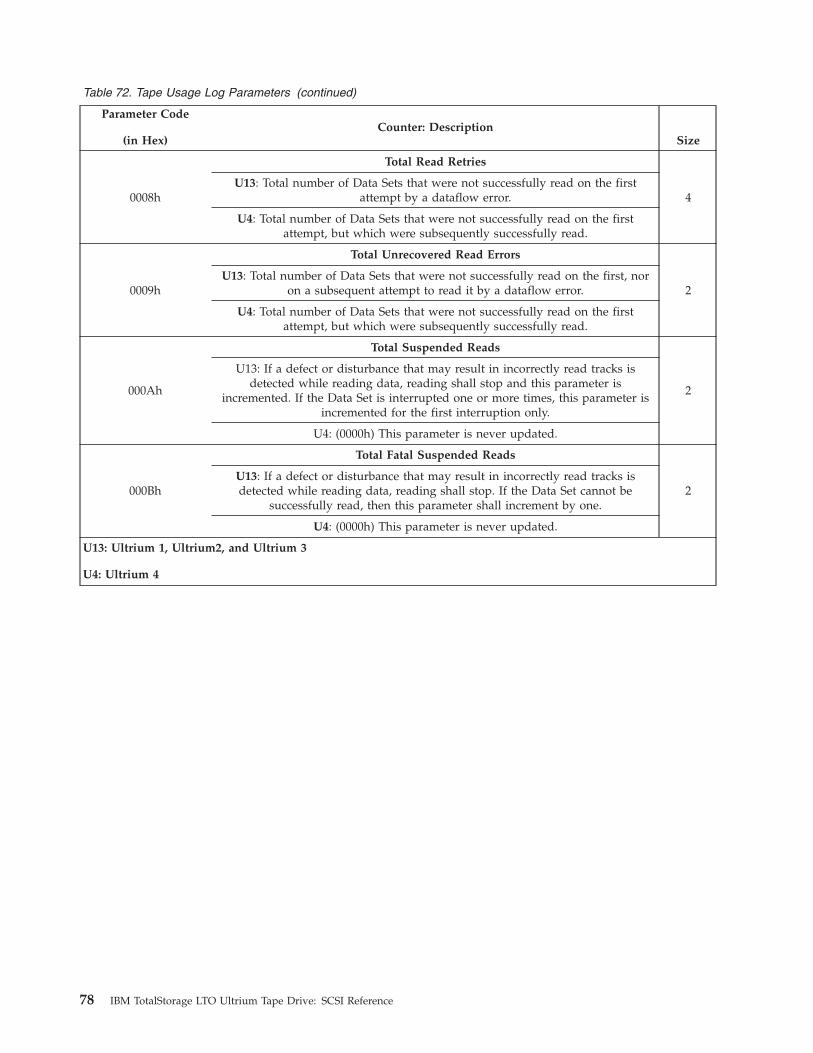
Table 72. Tape Usage Log Parameters (continued)
Parameter Code
(in Hex)
Counter: Description
Size
0008h
Total Read Retries
4
U13: Total number of Data Sets that were not successfully read on the first
attempt by a dataflow error.
U4: Total number of Data Sets that were not successfully read on the first
attempt, but which were subsequently successfully read.
0009h
Total Unrecovered Read Errors
2
U13: Total number of Data Sets that were not successfully read on the first, nor
on a subsequent attempt to read it by a dataflow error.
U4: Total number of Data Sets that were not successfully read on the first
attempt, but which were subsequently successfully read.
000Ah
Total Suspended Reads
2
U13: If a defect or disturbance that may result in incorrectly read tracks is
detected while reading data, reading shall stop and this parameter is
incremented. If the Data Set is interrupted one or more times, this parameter is
incremented for the first interruption only.
U4: (0000h) This parameter is never updated.
000Bh
Total Fatal Suspended Reads
2
U13: If a defect or disturbance that may result in incorrectly read tracks is
detected while reading data, reading shall stop. If the Data Set cannot be
successfully read, then this parameter shall increment by one.
U4: (0000h) This parameter is never updated.
U13: Ultrium 1, Ultrium2, and Ultrium 3
U4: Ultrium 4
78 IBM TotalStorage LTO Ultrium Tape Drive: SCSI Reference
Log Page 31h: Tape Capacity Log
The Tape Capacity Log Page Code is 31h. Parameters 2 and 4 are not supported
and are returned as 0. All parameter lengths are 4 bytes long. The supported fields
are listed in Table 73.
WARNING
Log parameter data must be dynamically parsed as some parameters may not
be present and other parameters may be inserted. The relative location of
parameters have changed and are anticipated to continue to change.
Table 73. Tape Capacity Log Parameters
Parameter Code
(in Hex)
Counter: Description Size
0001h
Main Partition Remaining Capacity: A representation of the location on
medium of EOD expressed in Native Capacity between EOD and EOP. This is
intended to be used as a gauge to display the percentage of medium used.
There is no guarantee that the amount of data expressed in this parameter will
be available for writing.
4
0002h
Alternate Partition Remaining Capacity: (Not supported - Always returns
00000000h)
4
0003h
Main Partition Maximum Capacity: (Constant value representing the Native
Capacity of the medium)
Ultrium 1: 0001 7487Ultrium 2: 0002 E90EUltrium 3: 0005 D21D
Ultrium 4: 000B A43B
4
0004h
Alternate Partition Maximum Capacity: (Not supported - Always returns
00000000h)
4
All parameters are in megabytes and assume no data compression. This data
cannot be reset or written.
Note: For this command, a megabyte is equal to 1 048 576 bytes. As an example, a
value of 17487h in Parameter 3 is equal to 95 367 megabytes, which is equal
to 100 000 000 000 bytes.
Chapter 3. Command Support 79
Log Page 32h: Data Compression Log
The Data Compression Log Page Code is 32h. Parameter byte fields 0 and 1 are 2
bytes long. Parameter byte fields 2 through 9 are each 4 bytes long.
The supported fields are listed in Table 74.
WARNING
Log parameter data must be dynamically parsed as some parameters may not
be present and other parameters may be inserted. The relative location of
parameters have changed and are anticipated to continue to change.
Table 74. Data Compression Log Parameters
Parameter Code
(in Hex)
Counter: Description Size
0000h Read Compression ratio x 100 2
0001h Write Compression Ratio x 100 2
0002h Megabytes transferred to server 4
0003h Bytes transferred to server 4
0004h Megabytes read from tape 4
0005h Bytes read from tape 4
0006h Megabytes transferred from server 4
0007h Bytes transferred from server 4
0008h Megabytes written to tape 4
0009h Bytes written to tape 4
Parameters 2 through 9 occur as pairs that represent a large number of bytes
transferred. The first 4-byte parameter represents the number of whole megabytes
transferred, rounded to the nearest megabyte. The second 4-byte parameter
represents the difference between this number of megabytes and the actual number
of bytes. This may be a signed quantity.
This data may be reset, but may not be written.
80 IBM TotalStorage LTO Ultrium Tape Drive: SCSI Reference
Log Page 33h: Write Errors (Not Ultrium 1 or Ultrium 2
non-RoHS)
This page contains detailed counters related to write operations. This page is reset
when a cartridge is loaded.
Note: When multiple errors occur on a data set, the counter that is updated is
generally based on the first error detected.
WARNING
Log parameter data must be dynamically parsed as some parameters may not
be present and other parameters may be inserted. The relative location of
parameters have changed and are anticipated to continue to change.
Table 75. Write Errors log parameter codes
Parameter Code
(in Hex)
Counter: Description Size
0000h
Data sets Corrected: ECC is done by hardware. This is driven by an excessive
CQs rewritten condition (TBD). Each count represents on data set in error that
was successfully corrected and written.
2
0001h
Servo Transients: ERP action was required because of a servo detected error and
the first retry was successfully in place (stop write without backhitch,that is,
servo write skip). Each count represents one data set in error that was
successfully recovered and written.
2
0002h
Data Transients: ERP action was required because of a readback check or ECC
detected error and the first retry was successfully in place (no backhitch). Each
count represents one data set in error that was successfully recovered and
written.
2
0003h
Velocity Events: A velocity control problem occurred. Each count represents on
occurrence, not just the count of affected data sets. Counts may include
occurrences from both temporary and permanent errors.
2
0004h
Servo Acquisition Temps: A servo error (servo dropout or off-track shutdown)
was detected while trying to acquire a DSS or data set at the beginning of a
write append sequence (motion). ERP action was required, and servo transient
condition criteria were not met. Each count represents one data set in error that
was successfully recovered and written.
2
0005h
Data Acquisition Temps: During read-back check, the read channel failed to
acquire a DSS or data set at the beginning of a write append sequence and no
servo error was reported. ERP action was required, and read/ECC transient
condition criteria were not met. Each count represents one data set in error that
was successfully recovered and written.
2
0006h
Servo Temps: A servo error (servo dropout or off-track shutdown) was detected
while writing data. ERP action was required, and servo transient condition
criteria were not met. Each count represents one data set in error that was
successfully recovered and written.
2
0007h
Data Temps: An uncorrectable error, CRC error, instantaneous speed variation
(ISV) error, or no ending burst error occurred during readback check of a data
set, and no servo error was reported. ERP action was required, and
readback/ECC transient condition criteria were not met. Each count represents
one data set in error that was successfully recovered and written.
2
0008h
Total Retries: The count of the total number of ERP actions. Each count
represents one occurrence, not just one time per data set. Counts may include
occurrences from both temporary and permanent errors.
2
Chapter 3. Command Support 81
Table 75. Write Errors log parameter codes (continued)
Parameter Code
(in Hex)
Counter: Description Size
0009h Vendor-Reserved 2
000Ah Vendor-Reserved (Bellcord) 2
000Bh
Servo Skip Events: The count of long servo write skips, extended DSS or long
spaces between data sets written. This is generally servo write skips, but may
also include other write scenarios. Each count represents one occurrence, not one
count per block. Counts may include occurrences from both temporary and
permanent errors.
2
000Ch
Housekeeping Events: The count of write problems in the Housekeeping Data
set Region. Each count represents one occurrence, not just one time per data set.
Counts may include occurrences from both temporary and permanent errors.
2
000Dh
FID Events: The count of write problems while processing the FID. Each count
represents one occurrence, not just one time per data set. Counts may include
occurrences from both temporary and permanent errors.
2
000Eh Vendor-Reserved (Blocks Lifted) 2
000Fh
Data set Underrun: The number of times that the drive overran the
bufferprocessing capability and had to stop and restart during a write. Each
count represents one occurrence, not just one time per write.
2
0010h Vendor-Reserved 2
0011h
Servo Position Events: The number of servo detected positional compare
discrepancies.
2
82 IBM TotalStorage LTO Ultrium Tape Drive: SCSI Reference
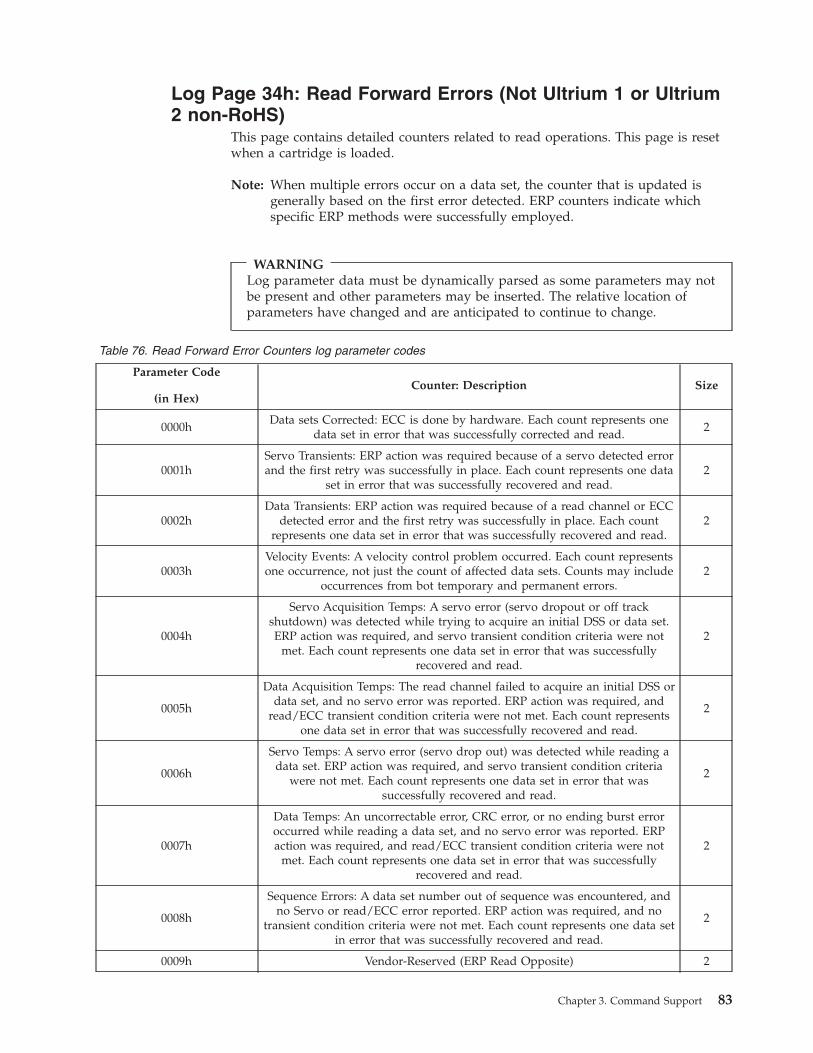
Log Page 34h: Read Forward Errors (Not Ultrium 1 or Ultrium
2 non-RoHS)
This page contains detailed counters related to read operations. This page is reset
when a cartridge is loaded.
Note: When multiple errors occur on a data set, the counter that is updated is
generally based on the first error detected. ERP counters indicate which
specific ERP methods were successfully employed.
WARNING
Log parameter data must be dynamically parsed as some parameters may not
be present and other parameters may be inserted. The relative location of
parameters have changed and are anticipated to continue to change.
Table 76. Read Forward Error Counters log parameter codes
Parameter Code
(in Hex)
Counter: Description Size
0000h
Data sets Corrected: ECC is done by hardware. Each count represents one
data set in error that was successfully corrected and read.
2
0001h
Servo Transients: ERP action was required because of a servo detected error
and the first retry was successfully in place. Each count represents one data
set in error that was successfully recovered and read.
2
0002h
Data Transients: ERP action was required because of a read channel or ECC
detected error and the first retry was successfully in place. Each count
represents one data set in error that was successfully recovered and read.
2
0003h
Velocity Events: A velocity control problem occurred. Each count represents
one occurrence, not just the count of affected data sets. Counts may include
occurrences from bot temporary and permanent errors.
2
0004h
Servo Acquisition Temps: A servo error (servo dropout or off track
shutdown) was detected while trying to acquire an initial DSS or data set.
ERP action was required, and servo transient condition criteria were not
met. Each count represents one data set in error that was successfully
recovered and read.
2
0005h
Data Acquisition Temps: The read channel failed to acquire an initial DSS or
data set, and no servo error was reported. ERP action was required, and
read/ECC transient condition criteria were not met. Each count represents
one data set in error that was successfully recovered and read.
2
0006h
Servo Temps: A servo error (servo drop out) was detected while reading a
data set. ERP action was required, and servo transient condition criteria
were not met. Each count represents one data set in error that was
successfully recovered and read.
2
0007h
Data Temps: An uncorrectable error, CRC error, or no ending burst error
occurred while reading a data set, and no servo error was reported. ERP
action was required, and read/ECC transient condition criteria were not
met. Each count represents one data set in error that was successfully
recovered and read.
2
0008h
Sequence Errors: A data set number out of sequence was encountered, and
no Servo or read/ECC error reported. ERP action was required, and no
transient condition criteria were not met. Each count represents one data set
in error that was successfully recovered and read.
2
0009h Vendor-Reserved (ERP Read Opposite) 2
Chapter 3. Command Support 83
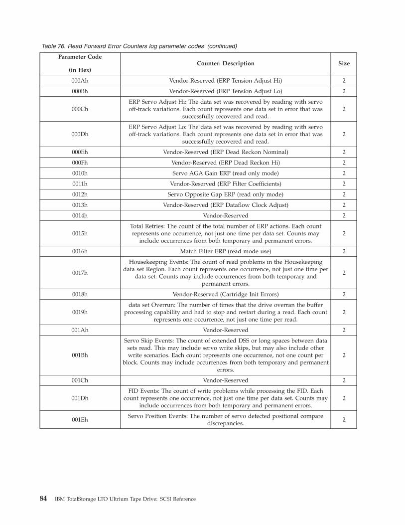
Table 76. Read Forward Error Counters log parameter codes (continued)
Parameter Code
(in Hex)
Counter: Description Size
000Ah Vendor-Reserved (ERP Tension Adjust Hi) 2
000Bh Vendor-Reserved (ERP Tension Adjust Lo) 2
000Ch
ERP Servo Adjust Hi: The data set was recovered by reading with servo
off-track variations. Each count represents one data set in error that was
successfully recovered and read.
2
000Dh
ERP Servo Adjust Lo: The data set was recovered by reading with servo
off-track variations. Each count represents one data set in error that was
successfully recovered and read.
2
000Eh Vendor-Reserved (ERP Dead Reckon Nominal) 2
000Fh Vendor-Reserved (ERP Dead Reckon Hi) 2
0010h Servo AGA Gain ERP (read only mode) 2
0011h Vendor-Reserved (ERP Filter Coefficients) 2
0012h Servo Opposite Gap ERP (read only mode) 2
0013h Vendor-Reserved (ERP Dataflow Clock Adjust) 2
0014h Vendor-Reserved 2
0015h
Total Retries: The count of the total number of ERP actions. Each count
represents one occurrence, not just one time per data set. Counts may
include occurrences from both temporary and permanent errors.
2
0016h Match Filter ERP (read mode use) 2
0017h
Housekeeping Events: The count of read problems in the Housekeeping
data set Region. Each count represents one occurrence, not just one time per
data set. Counts may include occurrences from both temporary and
permanent errors.
2
0018h Vendor-Reserved (Cartridge Init Errors) 2
0019h
data set Overrun: The number of times that the drive overran the buffer
processing capability and had to stop and restart during a read. Each count
represents one occurrence, not just one time per read.
2
001Ah Vendor-Reserved 2
001Bh
Servo Skip Events: The count of extended DSS or long spaces between data
sets read. This may include servo write skips, but may also include other
write scenarios. Each count represents one occurrence, not one count per
block. Counts may include occurrences from both temporary and permanent
errors.
2
001Ch Vendor-Reserved 2
001Dh
FID Events: The count of write problems while processing the FID. Each
count represents one occurrence, not just one time per data set. Counts may
include occurrences from both temporary and permanent errors.
2
001Eh
Servo Position Events: The number of servo detected positional compare
discrepancies.
2
84 IBM TotalStorage LTO Ultrium Tape Drive: SCSI Reference

Log Page 37h: Performance Characteristics (Ultrium 4)
This page includes various performance and capacity measurements across the
operation of the drive. Some fields are normalized qualitative measures while
others are quantitative. This page uses the Subpage Code mechanism (see “LOG
SENSE” on page 50) to select which groups of counters to return. This page has
three scopes controlled by the Subpage Code field. Each has different reset
characteristics which are described under the Subpage Code field description
below.
The subpage field in “LOG SENSE” on page 50 is used as follows:
Bit Description
7-6 Scope
Value Description
0h Transient values: reset on Log Select [all Subpages are reset]
1h Mount values: reset on load
2h Lifetime values: reset on device power on or device reset (not
target reset)
3h Vendor-Reserved
5-4 Level
Value Description
0h Return summary counters
1h Return basic counters
2h Return advanced counters
3-0 Group
Value Description
0h All groups
1h Host Interface
2h Buffer
3h Medium
4h Capacity
5h Load/Unload
6h Servo
The Subpage field in “LOG SELECT” on page 49 may be set to 00h when the page
code field is 37h. This operation will reset all group and local counters in the
transient scope. Other scope cannot be explicitly reset.
The individual log subpage and parameter codes are described in the following
table. Note that the counters which are returned depends on the Level and Group
fields in the subpage. A group value of 0h will return all counters of a level less
than or equal to that specified.
In the following tables, multiple counter codes may be represented by a single row.
There will be an aspect symbol in the counter code such as ’p’, ’q’, ’s’, or ’?’. The
Aspect(s) column indicates which of the following values applies to the given
code(s).
Aspect Definition
p=0 primary interface all ports (totals)
p=1 primary interface port 0
p=2 primary interface port 1
Chapter 3. Command Support 85
p=A automation interface (RS-422)
q=1 Non-Ready: NOTE: These commands include ALL commands which are
processed when the drive is in a Not Ready state.
q=2 Head-of-Queue: NOTE: These commands are commands which may be
processed in any order. Such commands include: Inquiry, Report LUNs,
Test Unit Ready and Request Sense. These counts are updated only when
the drive is in a Ready state.
q=2 Head-of-Queue: NOTE: These commands are commands which may be
processed in any order. Such commands include: Inquiry, Report LUNs,
Test Unit Ready and Request Sense. These counts are updated only when
the drive is in a Ready state.
q=3 Read: NOTE: This aspect has more features detailed below.
q=4 Write: NOTE: This aspect has more features detailed below.
q=5 Sync: NOTE: This aspect has more features detailed below.
q=6 Seek: NOTE: This aspect has more features detailed below.
q=7 Non-Medium: NOTE: These commands are command issued to LUN 0
which are not in any other applicable category. These include many
commands such as Log Sense, Log Select, Read Buffer, Reserve, etc. These
counts are updated only when the drive is in a Ready state.
q=8 Non-LUN0, Non-Ready: NOTE: These commands include ALL commands
which are processed by a LUN other than LUN 0 when the drive is in a
Not Ready state.
q=9 Non-LUN0, Head-of-Queue: NOTE: These commands are commands
which may be processed in any order. Such commands include: Inquiry,
Report LUNs, Test Unit Ready and Request Sense. These counts are
updated only when the drive is in a Ready state.
q=A Non-LUN0: NOTE: These commands include any commands processed by
a LUN other than LUN 0. These counts are updated only when the drive is
in a Ready state.
s=1 Speed 1: Highest read/write speed
s=2 Speed 2: Second highest read/write speed
s=3 Speed 3: Third highest read/write speed
s=4 Speed 4: Fourth highest read/write speed
s=5 Speed 5: Fifth highest read/write speed
s=6 Speed 6: Slowest read/write speed
s=F High speed locate (not read/write capable)
?=1 write - write phase without host holdoff. NOTE: if no (paused) data is
supported for a particular counter, this aspect will include all write
information
?=2 write (paused) - write phase while the host is being held off (buffer full)
?=3 read - read phase without host holdoff. NOTE: if no (paused) data is
supported for a particular counter, this aspect will include all read
information
?=4 read (paused) - read phase while the host is being held off (buffer empty)
86 IBM TotalStorage LTO Ultrium Tape Drive: SCSI Reference
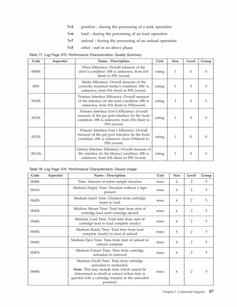
?=5 position - during the processing of a seek operation
?=6 load - during the processing of an load operation
?=7 unload - during the processing of an unload operation
?=F other - not in an above phase
Table 77. Log Page 37h: Performance Characteristics: Quality Summary
Code Aspect(s) Name : Description Unit Size Level Group
0000h
Drive Efficiency: Overall measure of the
drive’s condition. 00h is unknown, from 01h
(best) to FFh (worst)
rating 1 0 0
0001
Media Efficiency: Overall measure of the
currently mounted media’s condition. 00h’ is
unknown, from 01h (best) to FFh (worst)
rating 1 0 0
0010h
Primary Interface Efficiency: Overall measure
of the interface (to the host) condition. 00h is
unknown, from 01h (best) to FFh(worst)
rating 1 0 0
0011h
Primary Interface Port 0 Efficiency: Overall
measure of the per port interface (to the host)
condition. 00h is unknown, from 01h (best) to
FFh (worst)
rating 1 0 0
0012h
Primary Interface Port 1 Efficiency: Overall
measure of the per port interface (to the host)
condition. 00h is unknown, from 01h(best) to
FFh (worst)
rating 1 0 0
001Ah
Library Interface Efficiency: Overall measure of
the interface (to the library) condition. 00h is
unknown, from 01h (best) to FFh (worst)
rating 1 0 0
Table 78. Log Page 37h: Performance Characteristics: Device Usage
Code Aspect(s) Name : Description Unit Size Level Group
0040h Time: Amount of entire sample duration msec 6 2 5
0041h
Medium Empty Time: Duration without a tape
present
msec 6 2 5
0042h
Medium Insert Time: Duration from cartridge
insert to load
msec 6 2 5
0043h
Medium Mount Time: Total time from start of
cartridge load until cartridge ejected
msec 6 2 5
0044h
Medium Load Time: Total time from start of
cartridge load to load complete (ready)
msec 6 2 5
0045h
Medium Ready Time: Total time from load
complete (ready) to start of unload
msec 6 2 5
0046h
Medium Eject Time: Time from start of unload to
unload complete
msec 6 2 5
0047h
Medium Extract Time: Time from cartridge
unloaded to removed
msec 6 2 5
0048h
Medium Dwell Time: Time from cartridge
unloaded to (re)loaded.
Note: This may include time which cannot be
determined as dwell or extract (when time is
queried with a cartridge remains in the unloaded
position)
msec 6 2 5
Chapter 3. Command Support 87

Table 78. Log Page 37h: Performance Characteristics: Device Usage (continued)
Code Aspect(s) Name : Description Unit Size Level Group
0049h
Medium Clean Time: Time from cleaner recognized
to eject complete
msec 6 2 5
0051h
Medium Empty Count: Number of times tape was
fully removed
count 4 2 5
0052h
Medium Insert Count: Number of cartridge
insertions to load position detected
count 4 2 5
0053h
Medium Mount Count: Number of mount
operations
count 4 2 5
0054h Medium Load Count: Number of load operations count 4 2 5
0055h
Medium Ready Count: Number of ready
transisions
count 4 2 5
0056h Medium Eject Count: Number of unloads count 4 2 5
0057h
Medium Extract Count: Number of times tape was
extracted
count 4 2 5
0058h
Medium Dwell Count: Number of times tape was
reloaded (from unload)
count 4 2 5
0059h
Medium Clean Count: Number of recognized
cleaner loads (does not indicate successful cleans,
tape may be expired)
count 4 2 5
Table 79. Log Page 37h: Performance Characteristics: Host Commands
Code Aspect(s) Name : Description Unit Size Level Group
0q00h 12(3456)789A ... Count count 4 2 1
0q01h 12(3456)789A ... Timing msec 6 2 1
0q02h 12(3456)789A ... Relative Time % * 65536 4 1 1
0q04h 12(3456)789A ... Transfer Count to Host (in) count 4 2 1
0q05h 12(3456)789A ... Transfer Byte Count to Host (in) bytes 8 2 1
0q06h 12(3456)789A ... Transfer Timing to Host (in) msec 6 2 1
0q08h 12(4)789A ... Transfer Count from Host (out) count 4 2 1
0q09h 12(4)789A ... Transfer Byte Count from Host (out) bytes 8 2 1
0q0Ah 12(4)789A ... Transfer Timing from Host (out) msec 6 2 1
Note: Read type host commands include Read, Verify and Read Reverse (not all of these may be supported). These
counts are updated only when the drive is in a Ready state
0300h
Read Count: Number of blocks processed to the
host by read type commands
blocks 6 2 1
0301h
Read Timing: Amount of time processing read type
commands.
Note: Due to device specific performance path
resources, this may not reflect the actual time
spend processing commands, but may reflect the
amount of time where read commands could be
processed.
msec 6 2 1
0302h
Read Relative Time: Ratio of time spent reading
with respect to Medium Ready Time
% * 65536 4 1 1
0304h ... Transfer Count to Host (in) count 6 2 1
0305h ... Transfer Byte Count to Host (in) bytes 8 2 1
88 IBM TotalStorage LTO Ultrium Tape Drive: SCSI Reference
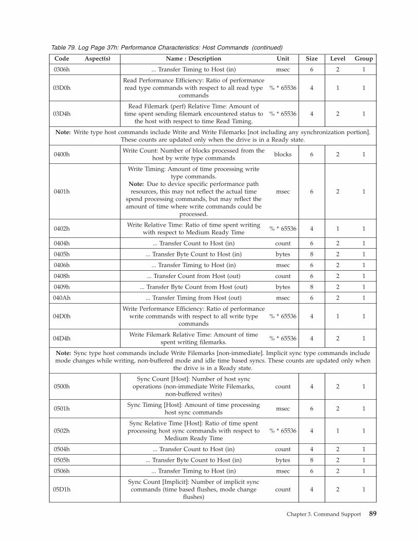
Table 79. Log Page 37h: Performance Characteristics: Host Commands (continued)
Code Aspect(s) Name : Description Unit Size Level Group
0306h ... Transfer Timing to Host (in) msec 6 2 1
03D0h
Read Performance Efficiency: Ratio of performance
read type commands with respect to all read type
commands
% * 65536 4 1 1
03D4h
Read Filemark (perf) Relative Time: Amount of
time spent sending filemark encountered status to
the host with respect to time Read Timing.
% * 65536 4 2 1
Note: Write type host commands include Write and Write Filemarks [not including any synchronization portion].
These counts are updated only when the drive is in a Ready state.
0400h
Write Count: Number of blocks processed from the
host by write type commands
blocks 6 2 1
0401h
Write Timing: Amount of time processing write
type commands.
Note: Due to device specific performance path
resources, this may not reflect the actual time
spend processing commands, but may reflect the
amount of time where write commands could be
processed.
msec 6 2 1
0402h
Write Relative Time: Ratio of time spent writing
with respect to Medium Ready Time
% * 65536 4 1 1
0404h ... Transfer Count to Host (in) count 6 2 1
0405h ... Transfer Byte Count to Host (in) bytes 8 2 1
0406h ... Transfer Timing to Host (in) msec 6 2 1
0408h ... Transfer Count from Host (out) count 6 2 1
0409h ... Transfer Byte Count from Host (out) bytes 8 2 1
040Ah ... Transfer Timing from Host (out) msec 6 2 1
04D0h
Write Performance Efficiency: Ratio of performance
write commands with respect to all write type
commands
% * 65536 4 1 1
04D4h
Write Filemark Relative Time: Amount of time
spent writing filemarks.
% * 65536 4 2 1
Note: Sync type host commands include Write Filemarks [non-immediate]. Implicit sync type commands include
mode changes while writing, non-buffered mode and idle time based syncs. These counts are updated only when
the drive is in a Ready state.
0500h
Sync Count [Host]: Number of host sync
operations (non-immediate Write Filemarks,
non-buffered writes)
count 4 2 1
0501h
Sync Timing [Host]: Amount of time processing
host sync commands
msec 6 2 1
0502h
Sync Relative Time [Host]: Ratio of time spent
processing host sync commands with respect to
Medium Ready Time
% * 65536 4 1 1
0504h ... Transfer Count to Host (in) count 4 2 1
0505h ... Transfer Byte Count to Host (in) bytes 8 2 1
0506h ... Transfer Timing to Host (in) msec 6 2 1
05D1h
Sync Count [Implicit]: Number of implicit sync
commands (time based flushes, mode change
flushes)
count 4 2 1
Chapter 3. Command Support 89
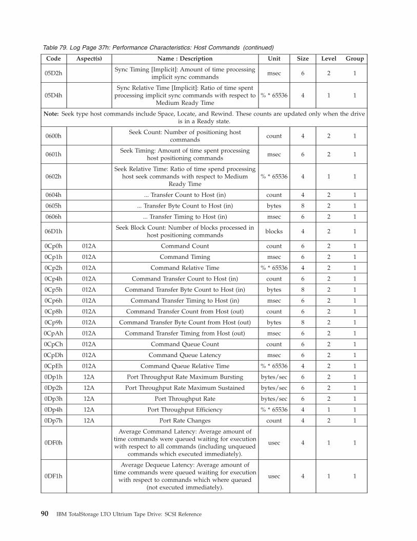
Table 79. Log Page 37h: Performance Characteristics: Host Commands (continued)
Code Aspect(s) Name : Description Unit Size Level Group
05D2h
Sync Timing [Implicit]: Amount of time processing
implicit sync commands
msec 6 2 1
05D4h
Sync Relative Time [Implicit]: Ratio of time spent
processing implicit sync commands with respect to
Medium Ready Time
% * 65536 4 1 1
Note: Seek type host commands include Space, Locate, and Rewind. These counts are updated only when the drive
is in a Ready state.
0600h
Seek Count: Number of positioning host
commands
count 4 2 1
0601h
Seek Timing: Amount of time spent processing
host positioning commands
msec 6 2 1
0602h
Seek Relative Time: Ratio of time spend processing
host seek commands with respect to Medium
Ready Time
% * 65536 4 1 1
0604h ... Transfer Count to Host (in) count 4 2 1
0605h ... Transfer Byte Count to Host (in) bytes 8 2 1
0606h ... Transfer Timing to Host (in) msec 6 2 1
06D1h
Seek Block Count: Number of blocks processed in
host positioning commands
blocks 4 2 1
0Cp0h 012A Command Count count 6 2 1
0Cp1h 012A Command Timing msec 6 2 1
0Cp2h 012A Command Relative Time % * 65536 4 2 1
0Cp4h 012A Command Transfer Count to Host (in) count 6 2 1
0Cp5h 012A Command Transfer Byte Count to Host (in) bytes 8 2 1
0Cp6h 012A Command Transfer Timing to Host (in) msec 6 2 1
0Cp8h 012A Command Transfer Count from Host (out) count 6 2 1
0Cp9h 012A Command Transfer Byte Count from Host (out) bytes 8 2 1
0CpAh 012A Command Transfer Timing from Host (out) msec 6 2 1
0CpCh 012A Command Queue Count count 6 2 1
0CpDh 012A Command Queue Latency msec 6 2 1
0CpEh 012A Command Queue Relative Time % * 65536 4 2 1
0Dp1h 12A Port Throughput Rate Maximum Bursting bytes/sec 6 2 1
0Dp2h 12A Port Throughput Rate Maximum Sustained bytes/sec 6 2 1
0Dp3h 12A Port Throughput Rate bytes/sec 6 2 1
0Dp4h 12A Port Throughput Efficiency % * 65536 4 1 1
0Dp7h 12A Port Rate Changes count 4 2 1
0DF0h
Average Command Latency: Average amount of
time commands were queued waiting for execution
with respect to all commands (including unqueued
commands which executed immediately).
usec 4 1 1
0DF1h
Average Dequeue Latency: Average amount of
time commands were queued waiting for execution
with respect to commands which where queued
(not executed immediately).
usec 4 1 1
90 IBM TotalStorage LTO Ultrium Tape Drive: SCSI Reference
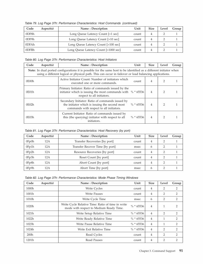
Table 79. Log Page 37h: Performance Characteristics: Host Commands (continued)
Code Aspect(s) Name : Description Unit Size Level Group
0DF8h Long Queue Latency Count [>1 sec] count 4 2 1
0DF9h Long Queue Latency Count [>10 sec] count 4 2 1
0DFAh Long Queue Latency Count [>100 sec] count 4 2 1
0DFBh Long Queue Latency Count [>1000 sec] count 4 2 1
Table 80. Log Page 37h: Performance Characteristics: Host Initiators
Code Aspect(s) Name : Description Unit Size Level Group
Note: In dual ported configurations it is possible for the same host to be identified as a different initiator when
using a different logical or physical path. This can occur in failover or load balancing applications.
0E00h
Active Initiator Count: Number of initiators which
executed one or more commands.
count 4 2 1
0E01h
Primary Initiator: Ratio of commands issued by the
initiator which is issuing the most commands with
respect to all initiators.
% * 65536 4 2 1
0E02h
Secondary Initiator: Ratio of commands issued by
the initiator which is issuing the second most
commands with respect to all initiators.
% * 65536 4 2 1
0E03h
Current Initiator: Ratio of commands issued by
this (the querying) initiator with respect to all
initiators.
% * 65536 4 2 1
Table 81. Log Page 37h: Performance Characteristics: Host Recovery (by port)
Code Aspect(s) Name : Description Unit Size Level Group
0Fp0h 12A Transfer Recoveries [by port] count 4 2 1
0Fp1h 12A Transfer Recover Time [by port] msec 6 2 1
0Fp2h 12A Resource Recoveries [by port] count 4 2 1
0Fp3h 12A Reset Count [by port] count 4 2 1
0Fp8h 12A Abort Count [by port] count 4 2 1
0Fp9h 12A Abort Time [by port] msec 6 2 1
Table 82. Log Page 37h: Performance Characteristics: Mode Phase Timing Windows
Code Aspect(s) Name : Description Unit Size Level Group
1000h Write Cycles count 4 2 2
1001h Write Pauses count 4 2 2
1010h Write Cycle Time msec 6 2 2
1020h
Write Cycle Relative Time: Ratio of time in write
mode with respect to Medium Ready Time.
% * 65536 4 1 2
1021h Write Setup Relative Time % * 65536 4 2 2
1022h Write Ready Relative Time % * 65536 4 1 2
1023h Write Pause Relative Time % * 65536 4 1 2
1024h Write Exit Relative Time % * 65536 4 2 2
200h Read Cycles count 4 2 2
1201h Read Pauses count 4 2 2
Chapter 3. Command Support 91
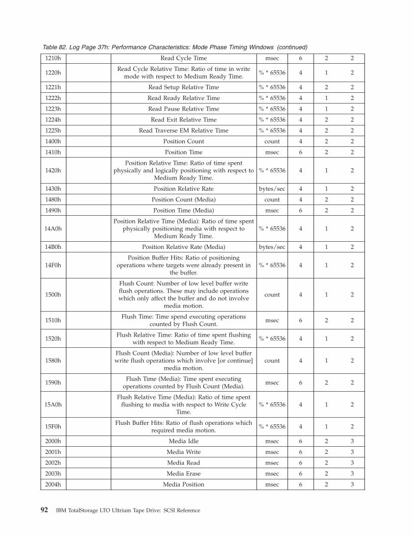
Table 82. Log Page 37h: Performance Characteristics: Mode Phase Timing Windows (continued)
1210h Read Cycle Time msec 6 2 2
1220h
Read Cycle Relative Time: Ratio of time in write
mode with respect to Medium Ready Time.
% * 65536 4 1 2
1221h Read Setup Relative Time % * 65536 4 2 2
1222h Read Ready Relative Time % * 65536 4 1 2
1223h Read Pause Relative Time % * 65536 4 1 2
1224h Read Exit Relative Time % * 65536 4 2 2
1225h Read Traverse EM Relative Time % * 65536 4 2 2
1400h Position Count count 4 2 2
1410h Position Time msec 6 2 2
1420h
Position Relative Time: Ratio of time spent
physically and logically positioning with respect to
Medium Ready Time.
% * 65536 4 1 2
1430h Position Relative Rate bytes/sec 4 1 2
1480h Position Count (Media) count 4 2 2
1490h Position Time (Media) msec 6 2 2
14A0h
Position Relative Time (Media): Ratio of time spent
physically positioning media with respect to
Medium Ready Time.
% * 65536 4 1 2
14B0h Position Relative Rate (Media) bytes/sec 4 1 2
14F0h
Position Buffer Hits: Ratio of positioning
operations where targets were already present in
the buffer.
% * 65536 4 1 2
1500h
Flush Count: Number of low level buffer write
flush operations. These may include operations
which only affect the buffer and do not involve
media motion.
count 4 1 2
1510h
Flush Time: Time spend executing operations
counted by Flush Count.
msec 6 2 2
1520h
Flush Relative Time: Ratio of time spent flushing
with respect to Medium Ready Time.
% * 65536 4 1 2
1580h
Flush Count (Media): Number of low level buffer
write flush operations which involve [or continue]
media motion.
count 4 1 2
1590h
Flush Time (Media): Time spent executing
operations counted by Flush Count (Media).
msec 6 2 2
15A0h
Flush Relative Time (Media): Ratio of time spent
flushing to media with respect to Write Cycle
Time.
% * 65536 4 1 2
15F0h
Flush Buffer Hits: Ratio of flush operations which
required media motion.
% * 65536 4 1 2
2000h Media Idle msec 6 2 3
2001h Media Write msec 6 2 3
2002h Media Read msec 6 2 3
2003h Media Erase msec 6 2 3
2004h Media Position msec 6 2 3
92 IBM TotalStorage LTO Ultrium Tape Drive: SCSI Reference
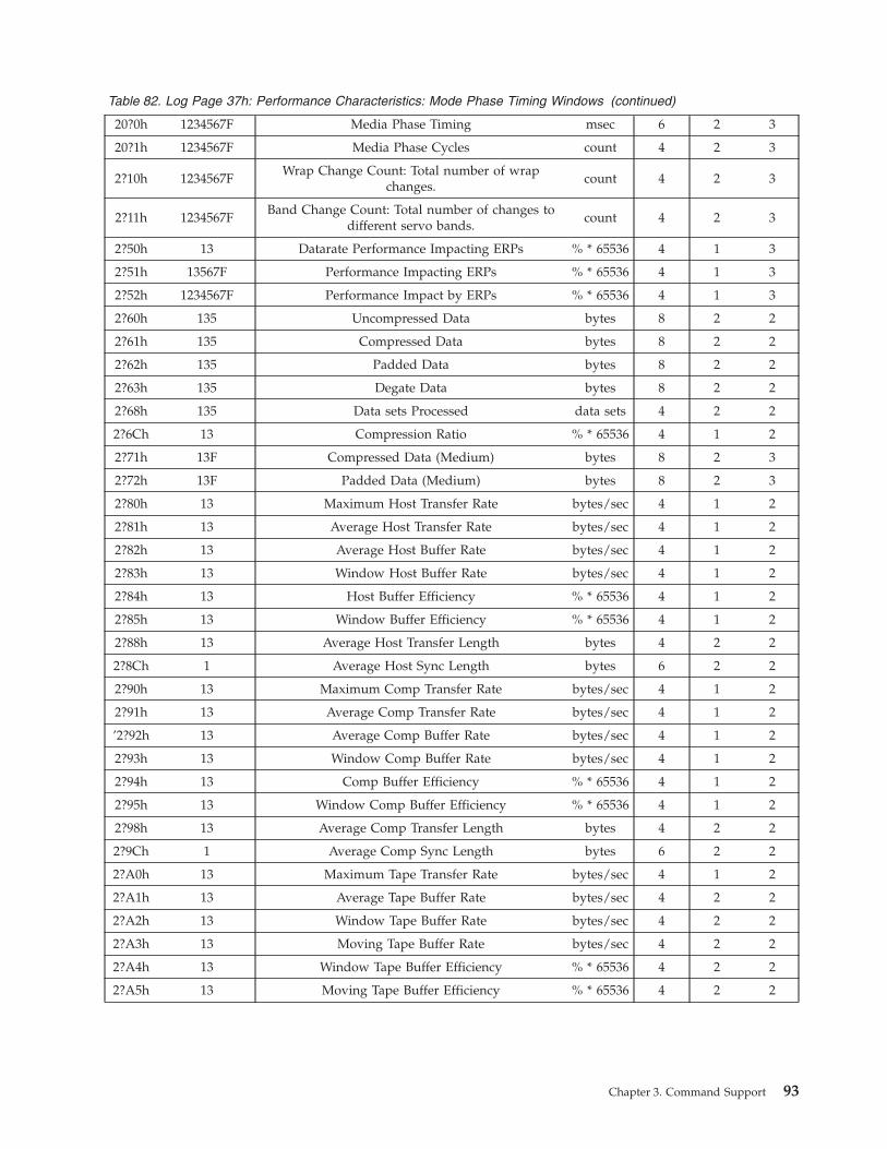
Table 82. Log Page 37h: Performance Characteristics: Mode Phase Timing Windows (continued)
20?0h 1234567F Media Phase Timing msec 6 2 3
20?1h 1234567F Media Phase Cycles count 4 2 3
2?10h 1234567F
Wrap Change Count: Total number of wrap
changes.
count 4 2 3
2?11h 1234567F
Band Change Count: Total number of changes to
different servo bands.
count 4 2 3
2?50h 13 Datarate Performance Impacting ERPs % * 65536 4 1 3
2?51h 13567F Performance Impacting ERPs % * 65536 4 1 3
2?52h 1234567F Performance Impact by ERPs % * 65536 4 1 3
2?60h 135 Uncompressed Data bytes 8 2 2
2?61h 135 Compressed Data bytes 8 2 2
2?62h 135 Padded Data bytes 8 2 2
2?63h 135 Degate Data bytes 8 2 2
2?68h 135 Data sets Processed data sets 4 2 2
2?6Ch 13 Compression Ratio % * 65536 4 1 2
2?71h 13F Compressed Data (Medium) bytes 8 2 3
2?72h 13F Padded Data (Medium) bytes 8 2 3
2?80h 13 Maximum Host Transfer Rate bytes/sec 4 1 2
2?81h 13 Average Host Transfer Rate bytes/sec 4 1 2
2?82h 13 Average Host Buffer Rate bytes/sec 4 1 2
2?83h 13 Window Host Buffer Rate bytes/sec 4 1 2
2?84h 13 Host Buffer Efficiency % * 65536 4 1 2
2?85h 13 Window Buffer Efficiency % * 65536 4 1 2
2?88h 13 Average Host Transfer Length bytes 4 2 2
2?8Ch 1 Average Host Sync Length bytes 6 2 2
2?90h 13 Maximum Comp Transfer Rate bytes/sec 4 1 2
2?91h 13 Average Comp Transfer Rate bytes/sec 4 1 2
’2?92h 13 Average Comp Buffer Rate bytes/sec 4 1 2
2?93h 13 Window Comp Buffer Rate bytes/sec 4 1 2
2?94h 13 Comp Buffer Efficiency % * 65536 4 1 2
2?95h 13 Window Comp Buffer Efficiency % * 65536 4 1 2
2?98h 13 Average Comp Transfer Length bytes 4 2 2
2?9Ch 1 Average Comp Sync Length bytes 6 2 2
2?A0h 13 Maximum Tape Transfer Rate bytes/sec 4 1 2
2?A1h 13 Average Tape Buffer Rate bytes/sec 4 2 2
2?A2h 13 Window Tape Buffer Rate bytes/sec 4 2 2
2?A3h 13 Moving Tape Buffer Rate bytes/sec 4 2 2
2?A4h 13 Window Tape Buffer Efficiency % * 65536 4 2 2
2?A5h 13 Moving Tape Buffer Efficiency % * 65536 4 2 2
Chapter 3. Command Support 93

Table 82. Log Page 37h: Performance Characteristics: Mode Phase Timing Windows (continued)
2?A6h 13
Tape Buffer Efficiency: Ratio of amount of time we
are usefully moving and ready with respect to
amount of time the buffer is able to process data.
A ratio larger than 1 indicates the compressed host
data is arriving faster than the native device rate.
Lower values indicate the device has underutilized
host bandwidth.
% * 65536 4 2 2
2?A7h 13F
Tape Thrashing: Ratio of amount of time we are
accelerating, decelerating or backhitching with
respect to the time in mode.
% * 65536 4 2 2
2?A8h 13F
Tape Efficiency: Ratio of amount of time we are
usefully moving and ready with respect to the
time in mode.
% * 65536 4 1 2
2?F0h 13 Speed Changes count 4 2 2
2?F1h 13 Speed Forced count 4 2 2
Table 83. Log Page 37h: Performance Characteristics: Servo Speed Characteristics
Code Aspect(s) Name : Description Unit Size Level Group
5Fs0h 123456F Servo Speed Relative Time % * 65536 4 2 6
Table 84. Log Page 37h: Performance Characteristics: Static Capacity
Code Aspect(s) Name : Description Unit Size Level Group
7000h Static Capacity Efficiency % * 65536 4 1 4
7010h Static Data sets Media data sets 4 2 4
7011h Static Data sets Used data sets 4 2 4
7020h Static Distance Media mm 8 2 4
7021h Static Distance Used mm 8 2 4
Table 85. Log Page 37h: Performance Characteristics: Active Capacity
Code Aspect(s) Name : Description Unit Size Level Group
7?00h 13F Active Capacity Efficiency % * 65536 4 1 4
7?10h 13F Active Sync Loss % * 65536 4 2 4
7?11h 13F Active Skip Loss % * 65536 4 2 4
7?12h 13F Active DSS Loss % * 65536 4 2 4
7?13h 13F Active CQs Loss (on-the-fly) % * 65536 4 2 4
7?21h 13F Active Distance Skip mm 8 2 4
7?22h 13F Active Distance DSS mm 8 2 4
7?23h 13F Active Distance CQs (on-the-fly) mm 8 2 4
7?2Fh 13F Active Distance Total mm 8 2 4
Note: The parameters in this page should be dynamically parsed as some
parameters may not be present and other parameters may be inserted.
94 IBM TotalStorage LTO Ultrium Tape Drive: SCSI Reference

Log Page 38h: Blocks/Bytes Transferred (Not Ultrium 1 or
Ultrium 2 non-RoHS)
This page is reset when a cartridge is loaded.
WARNING
Log parameter data must be dynamically parsed as some parameters may not
be present and other parameters may be inserted. The relative location of
parameters have changed and are anticipated to continue to change.
Table 86. Blocks/Bytes Transferred log parameter codes
Parameter Code
(in Hex)
Counter: Description Size
0000h
Host Write Blocks Processed: Each count represents a block processed across the
host interface during a Write. The count does not include ERP retries.
4
0001h
Host Write Kilobytes Processed: Each count represents a kilobyte (1024 bytes)
processed across the host interface during a Write. The count does not include
ERP retries. This count may be divided by Device Write Kilobytes Processed,
0005h, to calculate an approximate write comparison ratio.
4
0002h
Host Read Blocks Processed: Each count represents a block processed across the
host interface during a Read. The count does not include ERP retries.
4
0003h
Host Read Kilobytes Processed: Each count represents a kilobyte (1024 bytes)
processed across the host interface during a Read. The count does not include
ERP retries. This count may be divided by Device Read Kilobytes Processed,
0007h, to calculate an approximate read compression ratio.
4
0004h
Device Write Data sets Processed: Each count represents a data set processed on
the medium. The count does not include ERP retries.
4
0005h
Device Write Kilobytes Processed: Each count represents a kilobyte (1024 bytes)
processed on the medium. The count does not include ERP retries or any tape
formatting overhead bytes.
4
0006h
Device Read Data sets Processed: Each count represents a data set processed
from the medium. The count does not include ERP retries.
4
0007h
Device Read Kilobytes Processed: Each count represents a kilobyte (1024 bytes)
processed from the medium. The count does not include ERP retries or any tape
formatting overhead bytes.
4
0008h
Device Write Data sets Transferred: Each count represents a data set processed
on the medium. The count includes ERP retries.
4
0009h
Device Write Kilobytes Transferred: Each count represents a kilobyte (1024 bytes)
processed on the medium. The count includes ERP retries and any tape
formatting overhead bytes.
4
000Ah
Device Read Data sets Transferred: Each count represents a data set processed
from the medium. The count includes ERP retries.
4
000Bh
Device Read Kilobytes Transferred: Each count represents a kilobyte (1024 bytes)
processed from the medium. The count includes ERP retries and any tape
formatting overhead bytes.
4
000Ch
Nominal Capacity of Partition: The nominal capacity of the current partition (in
kilobytes).
4
000Dh
Fraction of Partition Traversed: The fractional part of the current partition
traversed (N/255).
1
Chapter 3. Command Support 95
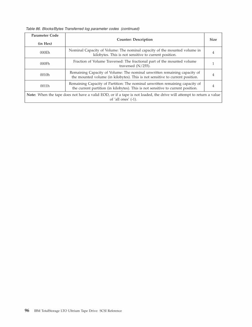
Table 86. Blocks/Bytes Transferred log parameter codes (continued)
Parameter Code
(in Hex)
Counter: Description Size
000Eh
Nominal Capacity of Volume: The nominal capacity of the mounted volume in
kilobytes. This is not sensitive to current position.
4
000Fh
Fraction of Volume Traversed: The fractional part of the mounted volume
traversed (N/255).
1
0010h
Remaining Capacity of Volume: The nominal unwritten remaining capacity of
the mounted volume (in kilobytes). This is not sensitive to current position.
4
0011h
Remaining Capacity of Partition: The nominal unwritten remaining capacity of
the current partition (in kilobytes). This is not sensitive to current position.
4
Note: When the tape does not have a valid EOD, or if a tape is not loaded, the drive will attempt to return a value
of ’all ones’ (-1).
96 IBM TotalStorage LTO Ultrium Tape Drive: SCSI Reference

Log Page 39h: Host Port 0 Interface Errors (Not Ultrium 1 or
Ultrium 2 non-RoHS)
This page shows the count of errors occurring on primary port 1 (while the device
is active on the interface).
WARNING
Log parameter data must be dynamically parsed as some parameters may not
be present and other parameters may be inserted. The relative location of
parameters have changed and are anticipated to continue to change.
Table 87. Host Port Interface log parameter codes
Parameter Code
(in Hex)
Counter: Description Size
0000h
Host Protocol Errors: Each count represents one occurrence. Counts may include
occurrences from both temporary and permanent errors. (On SAS drives, this
parameter is not returned. See Table 69 on page 74, Protocol-Specific log page for
SAS protocol error counts).
2
0007h
Host Aborts: Each count represents one occurrence. Counts may include
occurrences from both temporary and permanent errors.
2
0008h
Host Resets: Each count represents one occurrence. Counts may include
occurrences from both temporary and permanent errors.
2
0009h Vendor-Reserved 2
000Ah Vendor-Reserved 2
0010h
Host Recoveries: Each count represents one occurrence. Counts may include
occurrences from both temporary and permanent errors. An example of a host
recoveries is a Sequence Retransmission Request (SRR) on Fibre Channel drives.
(Not returned on SAS drives)
4
Chapter 3. Command Support 97
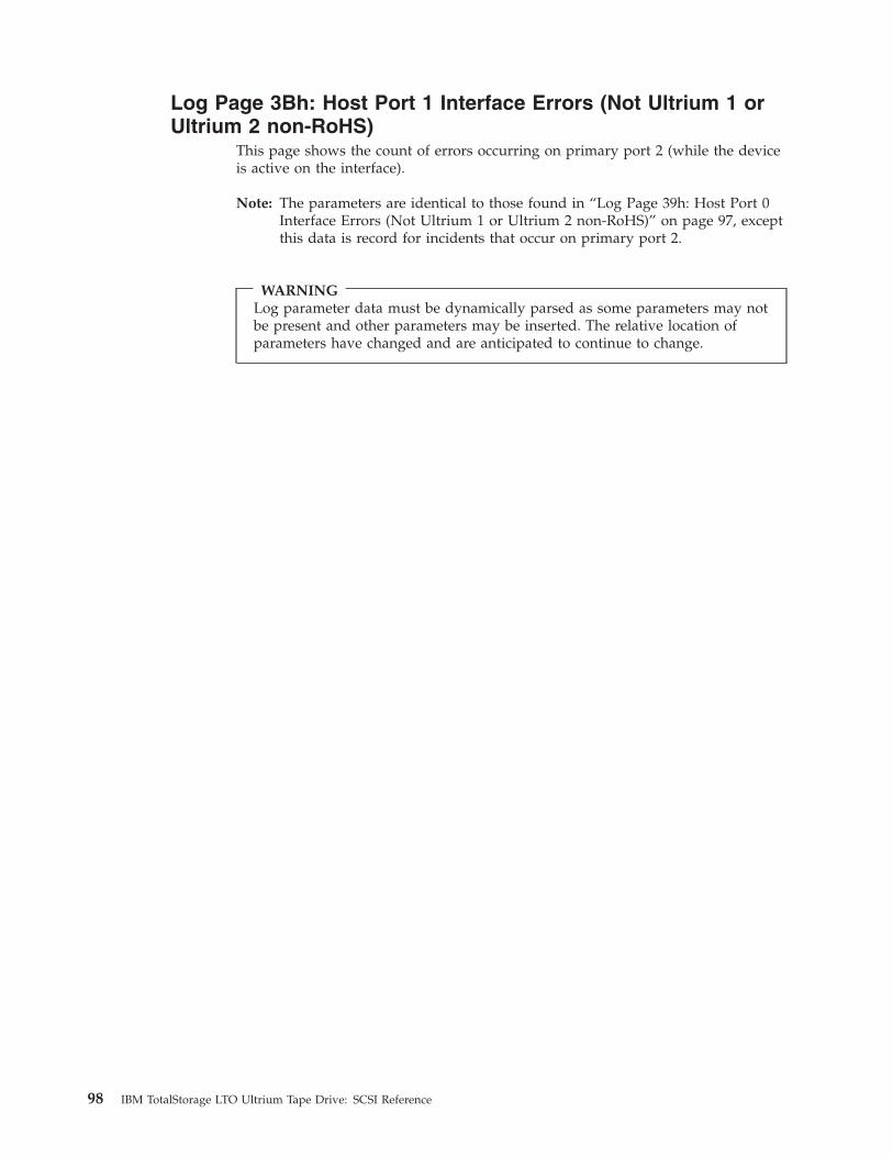
Log Page 3Bh: Host Port 1 Interface Errors (Not Ultrium 1 or
Ultrium 2 non-RoHS)
This page shows the count of errors occurring on primary port 2 (while the device
is active on the interface).
Note: The parameters are identical to those found in “Log Page 39h: Host Port 0
Interface Errors (Not Ultrium 1 or Ultrium 2 non-RoHS)” on page 97, except
this data is record for incidents that occur on primary port 2.
WARNING
Log parameter data must be dynamically parsed as some parameters may not
be present and other parameters may be inserted. The relative location of
parameters have changed and are anticipated to continue to change.
98 IBM TotalStorage LTO Ultrium Tape Drive: SCSI Reference
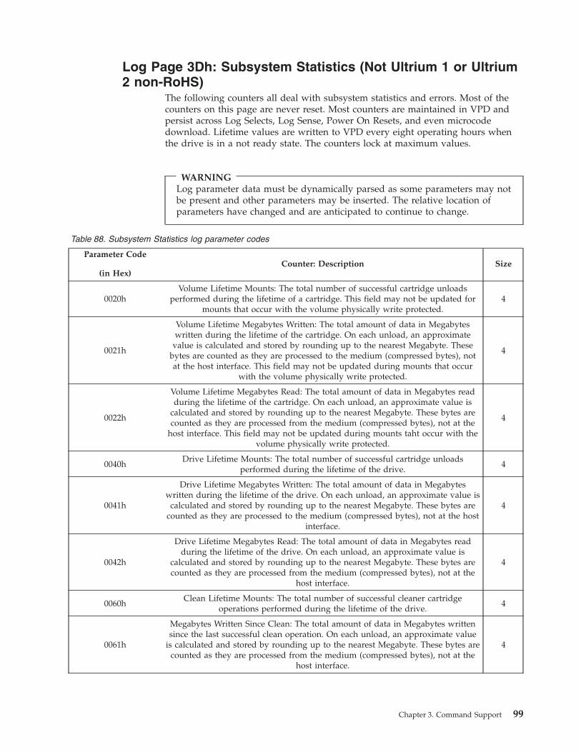
Log Page 3Dh: Subsystem Statistics (Not Ultrium 1 or Ultrium
2 non-RoHS)
The following counters all deal with subsystem statistics and errors. Most of the
counters on this page are never reset. Most counters are maintained in VPD and
persist across Log Selects, Log Sense, Power On Resets, and even microcode
download. Lifetime values are written to VPD every eight operating hours when
the drive is in a not ready state. The counters lock at maximum values.
WARNING
Log parameter data must be dynamically parsed as some parameters may not
be present and other parameters may be inserted. The relative location of
parameters have changed and are anticipated to continue to change.
Table 88. Subsystem Statistics log parameter codes
Parameter Code
(in Hex)
Counter: Description Size
0020h
Volume Lifetime Mounts: The total number of successful cartridge unloads
performed during the lifetime of a cartridge. This field may not be updated for
mounts that occur with the volume physically write protected.
4
0021h
Volume Lifetime Megabytes Written: The total amount of data in Megabytes
written during the lifetime of the cartridge. On each unload, an approximate
value is calculated and stored by rounding up to the nearest Megabyte. These
bytes are counted as they are processed to the medium (compressed bytes), not
at the host interface. This field may not be updated during mounts that occur
with the volume physically write protected.
4
0022h
Volume Lifetime Megabytes Read: The total amount of data in Megabytes read
during the lifetime of the cartridge. On each unload, an approximate value is
calculated and stored by rounding up to the nearest Megabyte. These bytes are
counted as they are processed from the medium (compressed bytes), not at the
host interface. This field may not be updated during mounts taht occur with the
volume physically write protected.
4
0040h
Drive Lifetime Mounts: The total number of successful cartridge unloads
performed during the lifetime of the drive.
4
0041h
Drive Lifetime Megabytes Written: The total amount of data in Megabytes
written during the lifetime of the drive. On each unload, an approximate value is
calculated and stored by rounding up to the nearest Megabyte. These bytes are
counted as they are processed to the medium (compressed bytes), not at the host
interface.
4
0042h
Drive Lifetime Megabytes Read: The total amount of data in Megabytes read
during the lifetime of the drive. On each unload, an approximate value is
calculated and stored by rounding up to the nearest Megabyte. These bytes are
counted as they are processed from the medium (compressed bytes), not at the
host interface.
4
0060h
Clean Lifetime Mounts: The total number of successful cleaner cartridge
operations performed during the lifetime of the drive.
4
0061h
Megabytes Written Since Clean: The total amount of data in Megabytes written
since the last successful clean operation. On each unload, an approximate value
is calculated and stored by rounding up to the nearest Megabyte. These bytes are
counted as they are processed from the medium (compressed bytes), not at the
host interface.
4
Chapter 3. Command Support 99
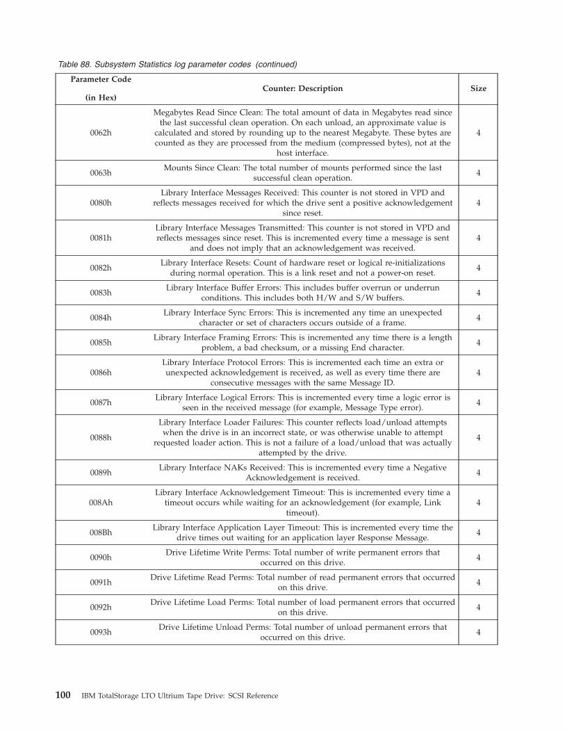
Table 88. Subsystem Statistics log parameter codes (continued)
Parameter Code
(in Hex)
Counter: Description Size
0062h
Megabytes Read Since Clean: The total amount of data in Megabytes read since
the last successful clean operation. On each unload, an approximate value is
calculated and stored by rounding up to the nearest Megabyte. These bytes are
counted as they are processed from the medium (compressed bytes), not at the
host interface.
4
0063h
Mounts Since Clean: The total number of mounts performed since the last
successful clean operation.
4
0080h
Library Interface Messages Received: This counter is not stored in VPD and
reflects messages received for which the drive sent a positive acknowledgement
since reset.
4
0081h
Library Interface Messages Transmitted: This counter is not stored in VPD and
reflects messages since reset. This is incremented every time a message is sent
and does not imply that an acknowledgement was received.
4
0082h
Library Interface Resets: Count of hardware reset or logical re-initializations
during normal operation. This is a link reset and not a power-on reset.
4
0083h
Library Interface Buffer Errors: This includes buffer overrun or underrun
conditions. This includes both H/W and S/W buffers.
4
0084h
Library Interface Sync Errors: This is incremented any time an unexpected
character or set of characters occurs outside of a frame.
4
0085h
Library Interface Framing Errors: This is incremented any time there is a length
problem, a bad checksum, or a missing End character.
4
0086h
Library Interface Protocol Errors: This is incremented each time an extra or
unexpected acknowledgement is received, as well as every time there are
consecutive messages with the same Message ID.
4
0087h
Library Interface Logical Errors: This is incremented every time a logic error is
seen in the received message (for example, Message Type error).
4
0088h
Library Interface Loader Failures: This counter reflects load/unload attempts
when the drive is in an incorrect state, or was otherwise unable to attempt
requested loader action. This is not a failure of a load/unload that was actually
attempted by the drive.
4
0089h
Library Interface NAKs Received: This is incremented every time a Negative
Acknowledgement is received.
4
008Ah
Library Interface Acknowledgement Timeout: This is incremented every time a
timeout occurs while waiting for an acknowledgement (for example, Link
timeout).
4
008Bh
Library Interface Application Layer Timeout: This is incremented every time the
drive times out waiting for an application layer Response Message.
4
0090h
Drive Lifetime Write Perms: Total number of write permanent errors that
occurred on this drive.
4
0091h
Drive Lifetime Read Perms: Total number of read permanent errors that occurred
on this drive.
4
0092h
Drive Lifetime Load Perms: Total number of load permanent errors that occurred
on this drive.
4
0093h
Drive Lifetime Unload Perms: Total number of unload permanent errors that
occurred on this drive.
4
100 IBM TotalStorage LTO Ultrium Tape Drive: SCSI Reference
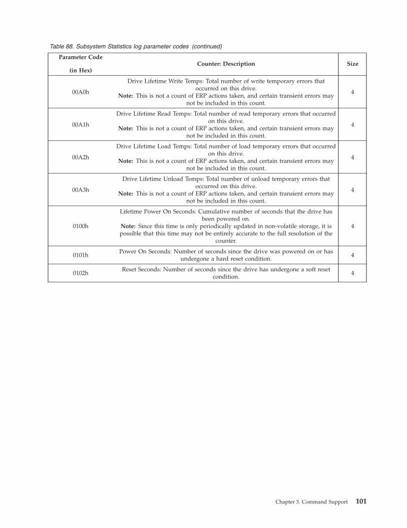
Table 88. Subsystem Statistics log parameter codes (continued)
Parameter Code
(in Hex)
Counter: Description Size
00A0h
Drive Lifetime Write Temps: Total number of write temporary errors that
occurred on this drive.
Note: This is not a count of ERP actions taken, and certain transient errors may
not be included in this count.
4
00A1h
Drive Lifetime Read Temps: Total number of read temporary errors that occurred
on this drive.
Note: This is not a count of ERP actions taken, and certain transient errors may
not be included in this count.
4
00A2h
Drive Lifetime Load Temps: Total number of load temporary errors that occurred
on this drive.
Note: This is not a count of ERP actions taken, and certain transient errors may
not be included in this count.
4
00A3h
Drive Lifetime Unload Temps: Total number of unload temporary errors that
occurred on this drive.
Note: This is not a count of ERP actions taken, and certain transient errors may
not be included in this count.
4
0100h
Lifetime Power On Seconds: Cumulative number of seconds that the drive has
been powered on.
Note: Since this time is only periodically updated in non-volatile storage, it is
possible that this time may not be entirely accurate to the full resolution of the
counter.
4
0101h
Power On Seconds: Number of seconds since the drive was powered on or has
undergone a hard reset condition.
4
0102h
Reset Seconds: Number of seconds since the drive has undergone a soft reset
condition.
4
Chapter 3. Command Support 101

Log Page 3Ch: Drive Usage Information
This page allows users to obtain the information last stored regarding the counts
accumulated over the life of the drive. Log Page 3Ch is returned in Log Page 00h.
This page is updated as events and tape pulling occurs. The nonvolatile memory is
updated upon error events, the tape being unthreaded, or when the cartridge
unloads. The counters are not cleared by any reset and cannot be changed with the
LOG SELECT command. If power is lost before the update data is written to the
nonvolatile memory, the counts are not updated.
Each parameter is a positive value. The counts do not overflow. Once a count
reaches its maximum value, that maximum value is always returned. The counts
do not roll over at the maximum value.
Table 89. Drive Usage Information Log Parameters
Parameter
Code (in
Hex)
Counter: Description Size
0001h
Write Media Blocks Counter: This counter is a lifetime statistic representing the number of
physical groups (i.e. Datasets) written during a write operation. Upon reaching the maximum
value, the counter does not wrap back to zero, but retains its maximum value
(FFFFFFFFFFFFFFFFh).
8
0002h
Rewrite Media Blocks Counter: This counter is a lifetime statistic representing the number of
physical groups (i.e. Datasets) rewritten during a write operation. Upon reaching the maximum
value, the counter does not wrap back to zero, but retains its maximum value
(FFFFFFFFFFFFFFFFh).
8
0003h
Read Media Blocks Counter: This counter is a lifetime statistic representing the number of
physical groups (i.e. Datasets) read during a read or space operation. The counter will not
increment/decrement during space reverse, space LEOP, or space fast operations. Upon
reaching the maximum value, the counter does not wrap back to zero, but retains its maximum
value (FFFFFFFFFFFFFFFFh).
8
0004h
Reread Media Blocks Counter: This counter is a lifetime statistic representing the number of
physical groups (i.e. Datasets) reread during a read operation. Upon reaching the maximum
value, the counter does not wrap back to zero, but retains its maximum value
(FFFFFFFFFFFFFFFFh).
8
000Eh Undefined Parameter (0000h) 2
000Fh Undefined Parameter (0000h) 2
0010h Undefined Parameter (0000h) 2
0011h
Clean Requested Flag: This flag indicates the drive should be cleaned.02h: Drive is not requesting clean03h: Drive is requesting clean
1
0012h Undefined Parameter (00h) 1
0013h Undefined Parameter (000000h) 3
0014h Undefined Parameter (000000h) 3
0015h
Cartridge Serial Number: This is right justified with leading spaces (20h). This value is update
on cartridge load and retained until the next cartridge load. If no cartridge has been loaded
since last power-on this value will be set to all spaces (20h).
12
102 IBM TotalStorage LTO Ultrium Tape Drive: SCSI Reference

MODE SELECT
The MODE SELECT command causes configuration data to be sent to the drive.
For the format of Mode data and supported Mode pages see “MODE SENSE” on
page 104. Both the 10-byte and 6-byte versions of the MODE SELECT command
are supported.
Table 90. 6-Byte MODE SELECT Command
Byte
Bit
7 6 5 4 3 2 1 0
0 Operation Code (15h)
1 Obsolete PF Reserved SP
2 Reserved
3 Reserved
4 Parameter List Length
5 Control
Table 91. 10-Byte MODE SELECT Command
Byte
Bit
7 6 5 4 3 2 1 0
0 Operation Code (55h)
1 Obsolete PF Reserved SP
2 Reserved
3 Reserved
4 Reserved
5 Reserved
6 Reserved
7
:
8
Parameter List Length
9 Control
The Page Format (PF) field may be any value. However, the drive assumes that the
format is SCSI-2. The Save Pages (SP) field is only allowed to be set to 1 when
explicitly mentioned in the description of the specific mode page. The Parameter
List Length field should be set to the amount of data to be sent to the drive.
The Parameter List Length field should be set to the amount of data to be sent to
the drive. The Parameter List Length value is checked to ensure that it is less than
or equal to the sum of the lengths of all the supported mode pages. Any command
with a larger value results in a Check Condition status. The associated sense data
returns with a Sense Key of Illegal Request and an ASC/ASCQ of Invalid Field in
CDB (2400).
If any of the fields in the Mode pages are invalid, no parameters are altered, Check
Condition status is returned, the Sense Key is set to Illegal Request, and the
ASC/ASCQ is set to Invalid Field in Parameter List (2600).
Chapter 3. Command Support 103

MODE SENSE
The MODE SENSE command requests that the drive send its configuration data to
the initiator. Pages 01h, 02h, 0Fh, 10h, and 1Ch are supported. Mode Pages 18h
and 19h are supported only on Fibre Channel drives . A page 3Fh request returns
all supported pages.
Both the 10-byte and the 6-byte versions of the command are supported.
Table 92. 6-Byte MODE SENSE Command
Byte
Bit
7 6 5 4 3 2 1 0
0 Operation Code (1Ah)
1 Obsolete Reserved DBD Reserved
2 PC Page Code
3 Reserved
4 Allocation Length
5 Control
Table 93. 10-Byte MODE SENSE Command
Byte
Bit
7 6 5 4 3 2 1 0
0 Operation Code (5Ah)
1 Obsolete Reserved DBD Reserved
2 PC Page Code
3 Reserved
4 Reserved
5 Reserved
6 Reserved
7
:
8
Allocation Length
9 Control
If the Disable Block Descriptors (DBD) field is set to 1, then no block descriptors
are returned with the mode data. If it is set to 0, then block descriptors are
returned.
The type of data returned is determined by the value of the Page Control (PC)
field as follows:
v 00b means the current configuration.
v 01b means the changeable bitmap (changeable = 1; unchangeable = 0).
v 10b means the default (power-on) values.
v 11b means the saved values. Because the drive does not support saved values,
the default values are returned.
104 IBM TotalStorage LTO Ultrium Tape Drive: SCSI Reference

The PC field only affects the mode parameters within the modes pages. It does not
affect the mode parameter header or the mode block descriptor. Within the mode
parameters, the PC field does not affect the PS field, the Page Code, or the
Additional Page Length fields. These fields will return the current values, as there
is no meaning if they are changed.
The Page Code must be set to the page to be returned.
Chapter 3. Command Support 105

Mode Data Format
Mode data returned by a MODE SENSE command or sent with a MODE SELECT
command consists of a Mode Parameter Header, an optional Mode Block
Descriptor, and zero or more Mode Parameter Pages.
Table 94. Mode Data Format
Byte
Bit
7 6 5 4 3 2 1 0
0
:
m
Mode Parameter Header
m + 1
:
m + 8
Mode Block Descriptor
m + 9
:
n
Mode Parameter Pages
106 IBM TotalStorage LTO Ultrium Tape Drive: SCSI Reference
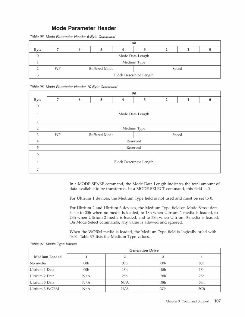
Mode Parameter Header
Table 95. Mode Parameter Header 6-Byte Command
Byte
Bit
7 6 5 4 3 2 1 0
0 Mode Data Length
1 Medium Type
2 WP Buffered Mode Speed
3 Block Descriptor Length
Table 96. Mode Parameter Header 10-Byte Command
Byte
Bit
7 6 5 4 3 2 1 0
0
:
1
Mode Data Length
2 Medium Type
3 WP Buffered Mode Speed
4 Reserved
5 Reserved
6
:
7
Block Descriptor Length
In a MODE SENSE command, the Mode Data Length indicates the total amount of
data available to be transferred. In a MODE SELECT command, this field is 0.
For Ultrium 1 devices, the Medium Type field is not used and must be set to 0.
For Ultrium 2 and Ultrium 3 devices, the Medium Type field on Mode Sense data
is set to 00h when no media is loaded, to 18h when Ultrium 1 media is loaded, to
28h when Ultrium 2 media is loaded, and to 38h when Ultrium 3 media is loaded.
On Mode Select commands, any value is allowed and ignored.
When the WORM media is loaded, the Medium Type field is logically or’ed with
0x04. Table 97 lists the Medium Type values.
Table 97. Media Type Values
Medium Loaded
Generation Drive
1 2 3 4
No media 00h 00h 00h 00h
Ultrium 1 Data 00h 18h 18h 18h
Ultrium 2 Data N/A 28h 28h 28h
Ultrium 3 Data N/A N/A 38h 38h
Ultrium 3 WORM N/A N/A 3Ch 3Ch
Chapter 3. Command Support 107
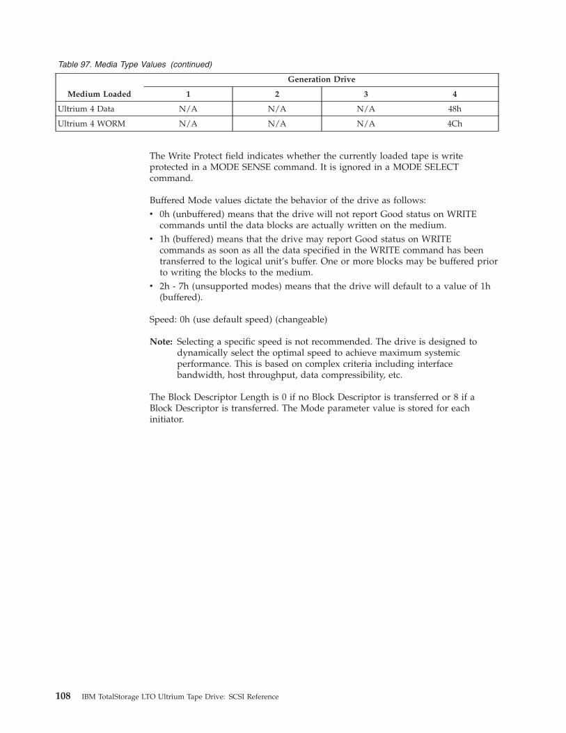
Table 97. Media Type Values (continued)
Medium Loaded
Generation Drive
1 2 3 4
Ultrium 4 Data N/A N/A N/A 48h
Ultrium 4 WORM N/A N/A N/A 4Ch
The Write Protect field indicates whether the currently loaded tape is write
protected in a MODE SENSE command. It is ignored in a MODE SELECT
command.
Buffered Mode values dictate the behavior of the drive as follows:
v 0h (unbuffered) means that the drive will not report Good status on WRITE
commands until the data blocks are actually written on the medium.
v 1h (buffered) means that the drive may report Good status on WRITE
commands as soon as all the data specified in the WRITE command has been
transferred to the logical unit’s buffer. One or more blocks may be buffered prior
to writing the blocks to the medium.
v 2h - 7h (unsupported modes) means that the drive will default to a value of 1h
(buffered).
Speed: 0h (use default speed) (changeable)
Note: Selecting a specific speed is not recommended. The drive is designed to
dynamically select the optimal speed to achieve maximum systemic
performance. This is based on complex criteria including interface
bandwidth, host throughput, data compressibility, etc.
The Block Descriptor Length is 0 if no Block Descriptor is transferred or 8 if a
Block Descriptor is transferred. The Mode parameter value is stored for each
initiator.
108 IBM TotalStorage LTO Ultrium Tape Drive: SCSI Reference
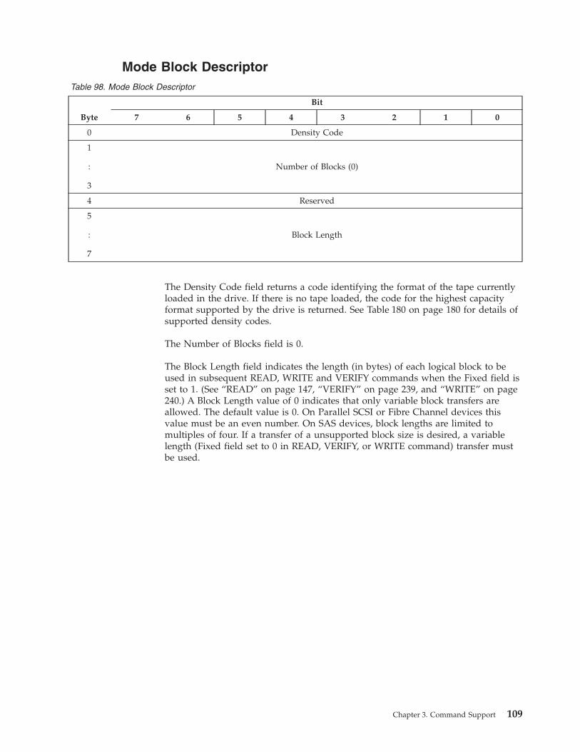
Mode Block Descriptor
Table 98. Mode Block Descriptor
Byte
Bit
7 6 5 4 3 2 1 0
0 Density Code
1
:
3
Number of Blocks (0)
4 Reserved
5
:
7
Block Length
The Density Code field returns a code identifying the format of the tape currently
loaded in the drive. If there is no tape loaded, the code for the highest capacity
format supported by the drive is returned. See Table 180 on page 180 for details of
supported density codes.
The Number of Blocks field is 0.
The Block Length field indicates the length (in bytes) of each logical block to be
used in subsequent READ, WRITE and VERIFY commands when the Fixed field is
set to 1. (See “READ” on page 147, “VERIFY” on page 239, and “WRITE” on page
240.) A Block Length value of 0 indicates that only variable block transfers are
allowed. The default value is 0. On Parallel SCSI or Fibre Channel devices this
value must be an even number. On SAS devices, block lengths are limited to
multiples of four. If a transfer of a unsupported block size is desired, a variable
length (Fixed field set to 0 in READ, VERIFY, or WRITE command) transfer must
be used.
Chapter 3. Command Support 109
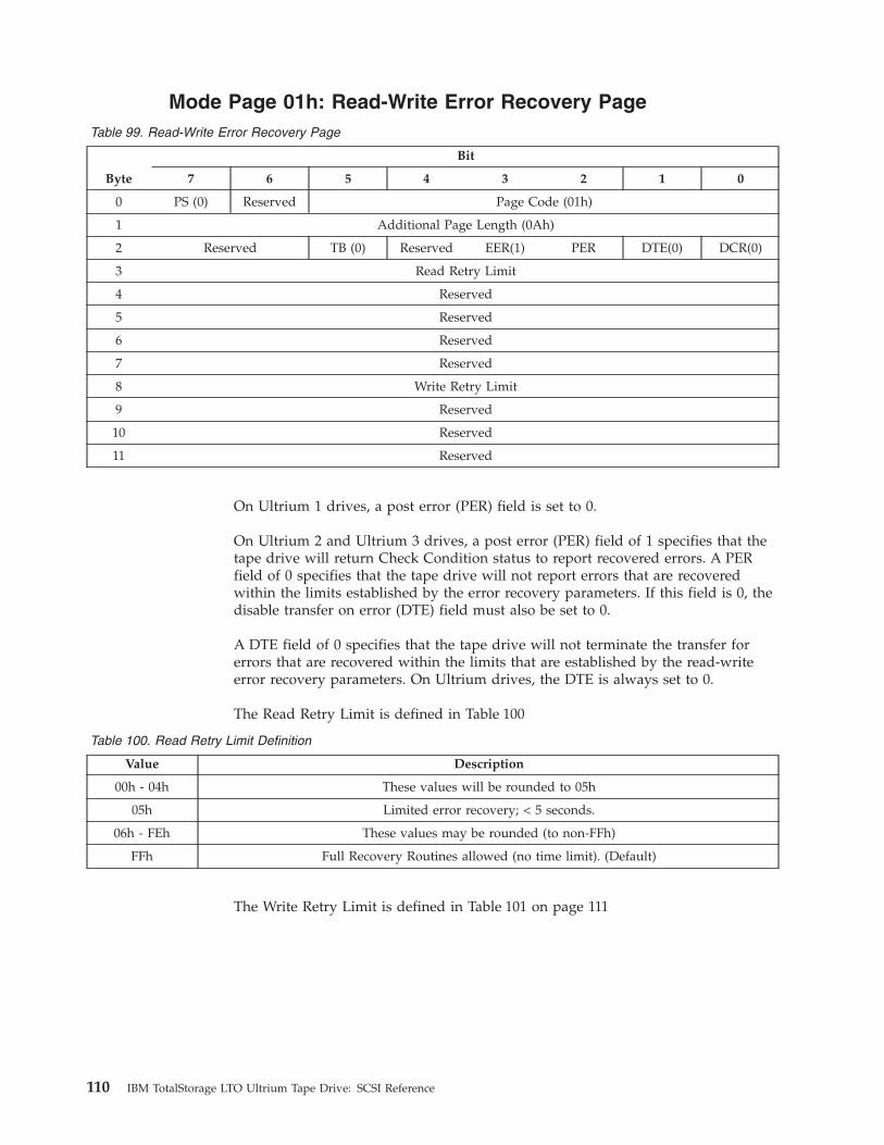
Mode Page 01h: Read-Write Error Recovery Page
Table 99. Read-Write Error Recovery Page
Byte
Bit
7 6 5 4 3 2 1 0
0 PS (0) Reserved Page Code (01h)
1 Additional Page Length (0Ah)
2 Reserved TB (0) Reserved EER(1) PER DTE(0) DCR(0)
3 Read Retry Limit
4 Reserved
5 Reserved
6 Reserved
7 Reserved
8 Write Retry Limit
9 Reserved
10 Reserved
11 Reserved
On Ultrium 1 drives, a post error (PER) field is set to 0.
On Ultrium 2 and Ultrium 3 drives, a post error (PER) field of 1 specifies that the
tape drive will return Check Condition status to report recovered errors. A PER
field of 0 specifies that the tape drive will not report errors that are recovered
within the limits established by the error recovery parameters. If this field is 0, the
disable transfer on error (DTE) field must also be set to 0.
A DTE field of 0 specifies that the tape drive will not terminate the transfer for
errors that are recovered within the limits that are established by the read-write
error recovery parameters. On Ultrium drives, the DTE is always set to 0.
The Read Retry Limit is defined in Table 100
Table 100. Read Retry Limit Definition
Value Description
00h - 04h These values will be rounded to 05h
05h Limited error recovery; < 5 seconds.
06h - FEh These values may be rounded (to non-FFh)
FFh Full Recovery Routines allowed (no time limit). (Default)
The Write Retry Limit is defined in Table 101 on page 111
110 IBM TotalStorage LTO Ultrium Tape Drive: SCSI Reference
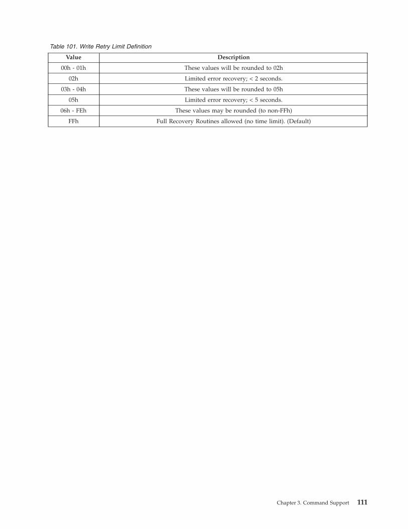
Table 101. Write Retry Limit Definition
Value Description
00h - 01h These values will be rounded to 02h
02h Limited error recovery; < 2 seconds.
03h - 04h These values will be rounded to 05h
05h Limited error recovery; < 5 seconds.
06h - FEh These values may be rounded (to non-FFh)
FFh Full Recovery Routines allowed (no time limit). (Default)
Chapter 3. Command Support 111
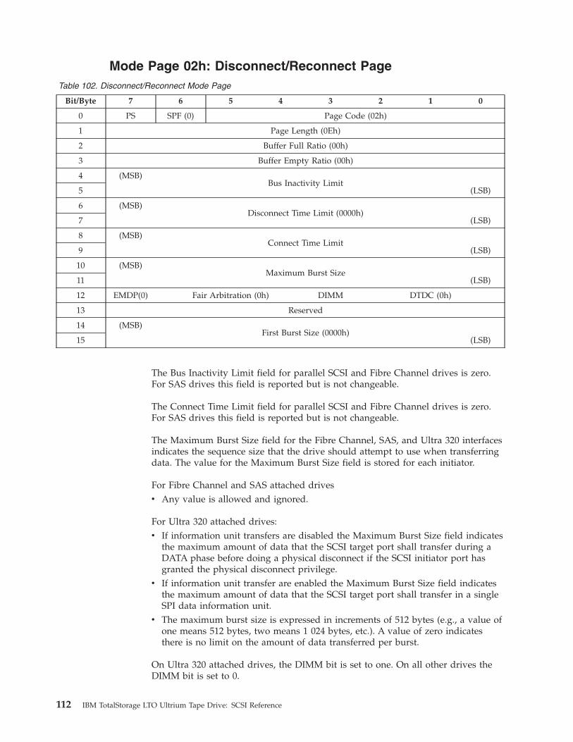
Mode Page 02h: Disconnect/Reconnect Page
Table 102. Disconnect/Reconnect Mode Page
Bit/Byte 7 6 5 4 3 2 1 0
0 PS SPF (0) Page Code (02h)
1 Page Length (0Eh)
2 Buffer Full Ratio (00h)
3 Buffer Empty Ratio (00h)
4 (MSB)
Bus Inactivity Limit
5 (LSB)
6 (MSB)
Disconnect Time Limit (0000h)
7 (LSB)
8 (MSB)
Connect Time Limit
9 (LSB)
10 (MSB)
Maximum Burst Size
11 (LSB)
12 EMDP(0) Fair Arbitration (0h) DIMM DTDC (0h)
13 Reserved
14 (MSB)
First Burst Size (0000h)
15 (LSB)
The Bus Inactivity Limit field for parallel SCSI and Fibre Channel drives is zero.
For SAS drives this field is reported but is not changeable.
The Connect Time Limit field for parallel SCSI and Fibre Channel drives is zero.
For SAS drives this field is reported but is not changeable.
The Maximum Burst Size field for the Fibre Channel, SAS, and Ultra 320 interfaces
indicates the sequence size that the drive should attempt to use when transferring
data. The value for the Maximum Burst Size field is stored for each initiator.
For Fibre Channel and SAS attached drives
v Any value is allowed and ignored.
For Ultra 320 attached drives:
v If information unit transfers are disabled the Maximum Burst Size field indicates
the maximum amount of data that the SCSI target port shall transfer during a
DATA phase before doing a physical disconnect if the SCSI initiator port has
granted the physical disconnect privilege.
v If information unit transfer are enabled the Maximum Burst Size field indicates
the maximum amount of data that the SCSI target port shall transfer in a single
SPI data information unit.
v The maximum burst size is expressed in increments of 512 bytes (e.g., a value of
one means 512 bytes, two means 1 024 bytes, etc.). A value of zero indicates
there is no limit on the amount of data transferred per burst.
On Ultra 320 attached drives, the DIMM bit is set to one. On all other drives the
DIMM bit is set to 0.
112 IBM TotalStorage LTO Ultrium Tape Drive: SCSI Reference
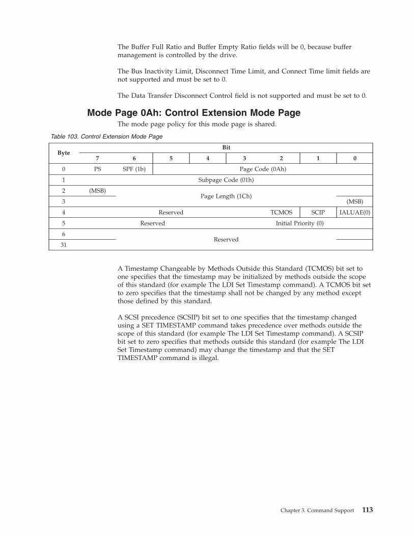
The Buffer Full Ratio and Buffer Empty Ratio fields will be 0, because buffer
management is controlled by the drive.
The Bus Inactivity Limit, Disconnect Time Limit, and Connect Time limit fields are
not supported and must be set to 0.
The Data Transfer Disconnect Control field is not supported and must be set to 0.
Mode Page 0Ah: Control Extension Mode Page
The mode page policy for this mode page is shared.
Table 103. Control Extension Mode Page
Byte
Bit
7 6 5 4 3 2 1 0
0 PS SPF (1b) Page Code (0Ah)
1 Subpage Code (01h)
2 (MSB)
Page Length (1Ch)
3 (MSB)
4 Reserved TCMOS SCIP IALUAE(0)
5 Reserved Initial Priority (0)
6
Reserved
31
A Timestamp Changeable by Methods Outside this Standard (TCMOS) bit set to
one specifies that the timestamp may be initialized by methods outside the scope
of this standard (for example The LDI Set Timestamp command). A TCMOS bit set
to zero specifies that the timestamp shall not be changed by any method except
those defined by this standard.
A SCSI precedence (SCSIP) bit set to one specifies that the timestamp changed
using a SET TIMESTAMP command takes precedence over methods outside the
scope of this standard (for example The LDI Set Timestamp command). A SCSIP
bit set to zero specifies that methods outside this standard (for example The LDI
Set Timestamp command) may change the timestamp and that the SET
TIMESTAMP command is illegal.
Chapter 3. Command Support 113
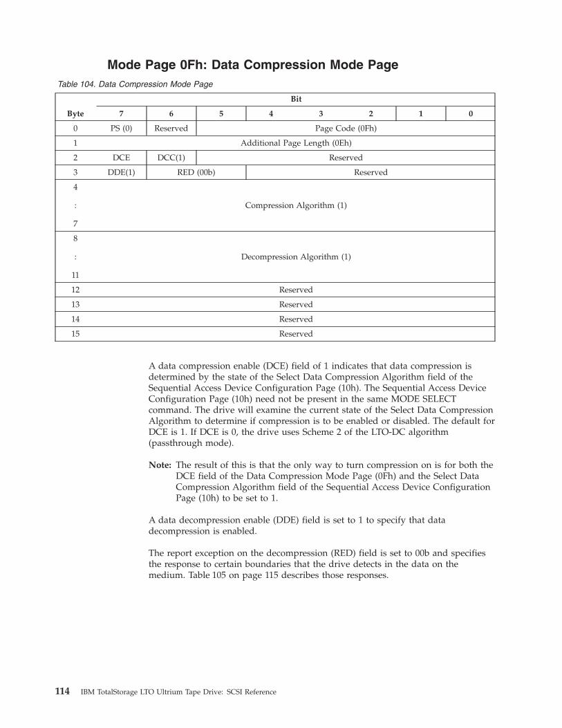
Mode Page 0Fh: Data Compression Mode Page
Table 104. Data Compression Mode Page
Byte
Bit
7 6 5 4 3 2 1 0
0 PS (0) Reserved Page Code (0Fh)
1 Additional Page Length (0Eh)
2 DCE DCC(1) Reserved
3 DDE(1) RED (00b) Reserved
4
:
7
Compression Algorithm (1)
8
:
11
Decompression Algorithm (1)
12 Reserved
13 Reserved
14 Reserved
15 Reserved
A data compression enable (DCE) field of 1 indicates that data compression is
determined by the state of the Select Data Compression Algorithm field of the
Sequential Access Device Configuration Page (10h). The Sequential Access Device
Configuration Page (10h) need not be present in the same MODE SELECT
command. The drive will examine the current state of the Select Data Compression
Algorithm to determine if compression is to be enabled or disabled. The default for
DCE is 1. If DCE is 0, the drive uses Scheme 2 of the LTO-DC algorithm
(passthrough mode).
Note: The result of this is that the only way to turn compression on is for both the
DCE field of the Data Compression Mode Page (0Fh) and the Select Data
Compression Algorithm field of the Sequential Access Device Configuration
Page (10h) to be set to 1.
A data decompression enable (DDE) field is set to 1 to specify that data
decompression is enabled.
The report exception on the decompression (RED) field is set to 00b and specifies
the response to certain boundaries that the drive detects in the data on the
medium. Table 105 on page 115 describes those responses.
114 IBM TotalStorage LTO Ultrium Tape Drive: SCSI Reference
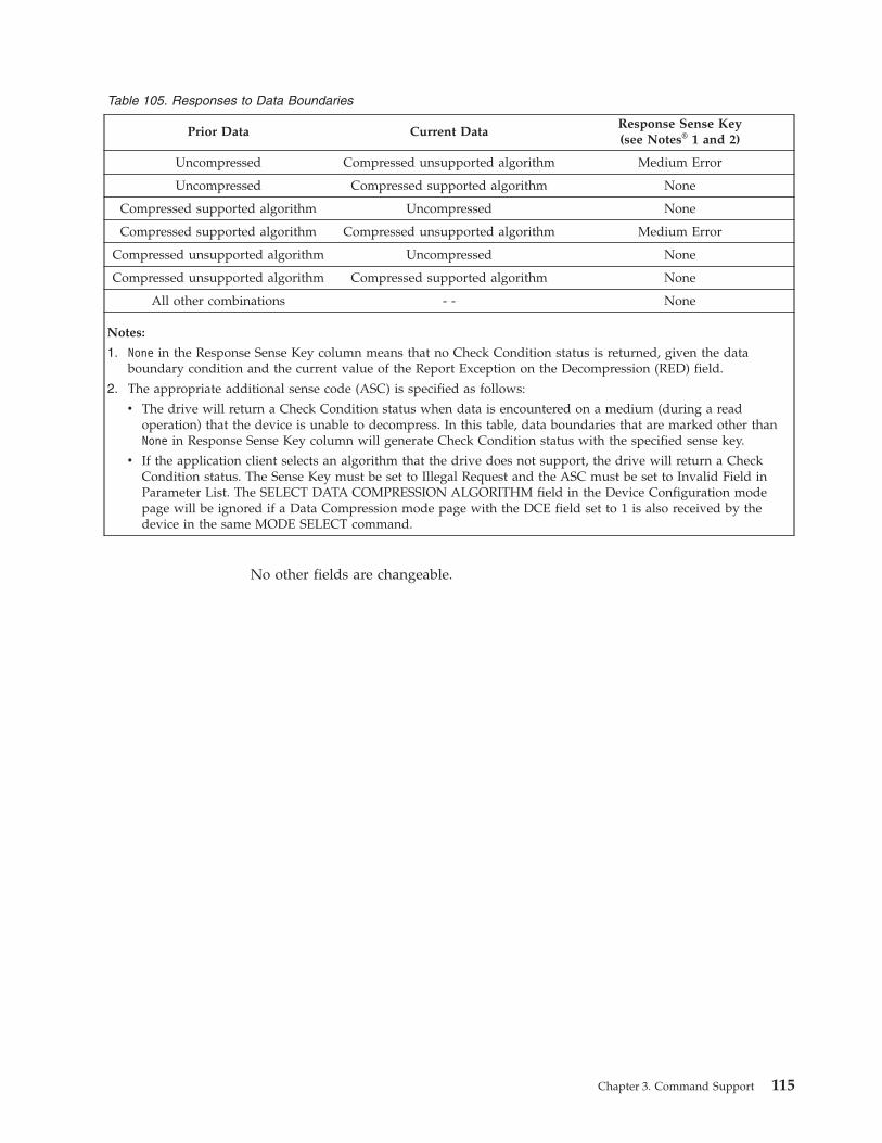
Table 105. Responses to Data Boundaries
Prior Data Current Data
Response Sense Key(see Notes® 1 and 2)
Uncompressed Compressed unsupported algorithm Medium Error
Uncompressed Compressed supported algorithm None
Compressed supported algorithm Uncompressed None
Compressed supported algorithm Compressed unsupported algorithm Medium Error
Compressed unsupported algorithm Uncompressed None
Compressed unsupported algorithm Compressed supported algorithm None
All other combinations - - None
Notes:
1. None in the Response Sense Key column means that no Check Condition status is returned, given the data
boundary condition and the current value of the Report Exception on the Decompression (RED) field.
2. The appropriate additional sense code (ASC) is specified as follows:
v The drive will return a Check Condition status when data is encountered on a medium (during a read
operation) that the device is unable to decompress. In this table, data boundaries that are marked other than
None in Response Sense Key column will generate Check Condition status with the specified sense key.
v If the application client selects an algorithm that the drive does not support, the drive will return a Check
Condition status. The Sense Key must be set to Illegal Request and the ASC must be set to Invalid Field in
Parameter List. The SELECT DATA COMPRESSION ALGORITHM field in the Device Configuration mode
page will be ignored if a Data Compression mode page with the DCE field set to 1 is also received by the
device in the same MODE SELECT command.
No other fields are changeable.
Chapter 3. Command Support 115

Mode Page 10h: Sequential Access Device Configuration Page
Table 106. Sequential Access Device Configuration Page
Byte
Bit
7 6 5 4 3 2 1 0
0 PS (0) Reserved Page Code (10h)
1 Additional Page Length (0Eh)
2 Reserved CAP (0) CAF (0) Active Format (0)
3 Active Partition (0)
4 Write Buffer Full Ratio (0)
5 Read Buffer Empty Ratio (0)
6
:
7
Write Delay Time
8 DBR (0) BIS (1) RSmk (0) AVC (0) SOCF (0) RBO (0) REW (0)
9 Gap Size (0)
10 ED Defined (0) EEG (1) SEW (0) SWP (0) Reserved
11
:
13
Buffer Size at Early Warning (0)
14 Select Data Compression Algorithm
15 WTRE OIR Rewind on Reset (0) ASOCWP
(0)
PERSWP
(0)
PRMWP (0)
The WRITE DELAY TIME field specifies the maximum time, in 100 ms increments,
that the device server should wait before any buffered data that is to be written, is
forced to the medium after the last buffered WRITE command that did not cause
the object buffer to exceed the write object buffer full ratio.
WARNING
Changing the Write Delay Time may result in adverse performance
The Active Partition field will be 0 because multiple partitions are not supported.
The Change Active Format (CAF) and Active Format fields will be 0 because
changing formats is not supported.
The Write Buffer Full Ratio and Read Buffer Empty Ratio fields will be 0 because
buffer management is done by the drive.
The Data Buffer Recovery (DBR), Report Set Marks (RSmk), Stop On Consecutive
File Marks (SOCF), Recover Buffer Order (RBO), Report Early Warning on Read
(REW), and Synchronize at Early Warning fields must be set to 0 because these
features are not supported.
116 IBM TotalStorage LTO Ultrium Tape Drive: SCSI Reference

The Automatic Velocity Control (AVC) field must be set to 0 because velocity
control is managed by the drive.
The Gap Size field must be set to 0 because there is no concept of inter-block gaps
in the format.
The Block Identifiers Supported (BIS) field must be set to 1 because block
identifiers are supported.
The enable EOD generation (EEG) field must be set to 1 because the drive always
generates EOD.
The Buffer Size at Early Warning field will be 0, as this cannot be set.
The default value for the Select Data Compression Algorithm is 1 and indicates
that data compression is enabled if the state of the DCE field of the Data
Compression Mode Page (0Fh) is set to 1. The Data Compression Mode Page (0Fh)
need not be present in the same MODE SELECT command. The drive will examine
the current state of the DCE to determine if compression is to be enabled or
disabled. If Select Data Compression Algorithm is 0, the drive uses Scheme 2 of the
LTO-DC algorithm (passthrough mode).
Note: The result of this is that the only way to turn compression on is for both the
DCE field of the Data Compression Mode Page (0Fh) and the Select Data
Compression Algorithm field of the Sequential Access Device Configuration
Page (10h) to be set to 1.
The WORM Tamper Read Enable (WTRE) field is supported only on Ultrium 3
drives.
The WORM Tamper Read Enable (WTRE) field has no effect on the processing of a
locate, read, space, or verify operation when the drive contains a non-WORM
medium.
Only If Reserved (OIR): Changeable on some Ultrium 3 code levels. Default is
zero. Set to zero and not changeable on Ultrium 1 and Ultrium 2 drives.
The WTRE field specifies how the drive responds to detection of compromised
integrity of a WORM medium when processing a locate, read, space, or verify
operation.
Value Action Taken by Drive
00b
If the drive detects compromised integrity on a WORM medium, it will return CHECK
CONDITION status and set the sense key to MEDIUM ERROR and the additional sense code
to WORM MEDIUM - INTEGRITY CHECK. (3/300Dh).
The position of the medium may have changed.
01b
Detection of compromised integrity on a WORM medium shall not affect processing of a task.
Note: An application client should set the WTRE bit to 01b only for the recovery of data from
a WORM medium where the integrity of the stored data has been compromised.
10b
If the drive detects compromised integrity on a WORM medium it will return CHECK
CONDITION status and set the sense key to MEDIUM ERROR and the additional sense code
to WORM MEDIUM - INTEGRITY CHECK. (3/300Dh).
The position of the medium may have changed.
11b Reserved
Chapter 3. Command Support 117

The drive sets the WTRE field to 10b following a unit attention condition for a
not-ready-to-ready transition.
118 IBM TotalStorage LTO Ultrium Tape Drive: SCSI Reference
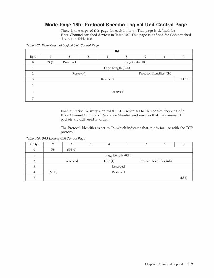
Mode Page 18h: Protocol-Specific Logical Unit Control Page
There is one copy of this page for each initiator. This page is defined for
Fibre-Channel-attached devices in Table 107. This page is defined for SAS attached
devices in Table 108.
Table 107. Fibre Channel Logical Unit Control Page
Byte
Bit
7 6 5 4 3 2 1 0
0 PS (0) Reserved Page Code (18h)
1 Page Length (06h)
2 Reserved Protocol Identifier (0h)
3 Reserved EPDC
4
:
7
Reserved
Enable Precise Delivery Control (EPDC), when set to 1b, enables checking of a
Fibre Channel Command Reference Number and ensures that the command
packets are delivered in order.
The Protocol Identifier is set to 0h, which indicates that this is for use with the FCP
protocol.
Table 108. SAS Logical Unit Control Page
Bit/Byte 7 6 5 4 3 2 1 0
0 PS SPF(0)
1 Page Length (06h)
2 Reserved TLR (1) Protocol Identifier (6h)
3 Reserved
4 (MSB) Reserved
7 (LSB)
Chapter 3. Command Support 119
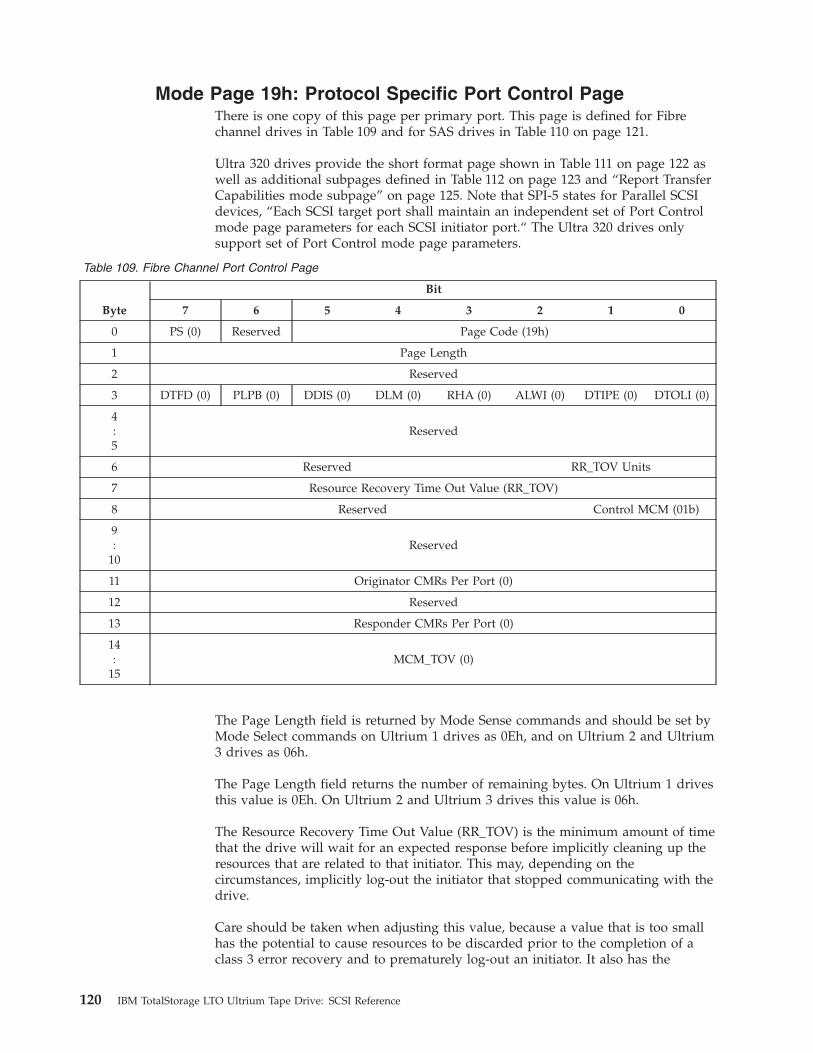
Mode Page 19h: Protocol Specific Port Control Page
There is one copy of this page per primary port. This page is defined for Fibre
channel drives in Table 109 and for SAS drives in Table 110 on page 121.
Ultra 320 drives provide the short format page shown in Table 111 on page 122 as
well as additional subpages defined in Table 112 on page 123 and “Report Transfer
Capabilities mode subpage” on page 125. Note that SPI-5 states for Parallel SCSI
devices, “Each SCSI target port shall maintain an independent set of Port Control
mode page parameters for each SCSI initiator port.“ The Ultra 320 drives only
support set of Port Control mode page parameters.
Table 109. Fibre Channel Port Control Page
Byte
Bit
7 6 5 4 3 2 1 0
0 PS (0) Reserved Page Code (19h)
1 Page Length
2 Reserved
3 DTFD (0) PLPB (0) DDIS (0) DLM (0) RHA (0) ALWI (0) DTIPE (0) DTOLI (0)
4
:
5
Reserved
6 Reserved RR_TOV Units
7 Resource Recovery Time Out Value (RR_TOV)
8 Reserved Control MCM (01b)
9
:
10
Reserved
11 Originator CMRs Per Port (0)
12 Reserved
13 Responder CMRs Per Port (0)
14
:
15
MCM_TOV (0)
The Page Length field is returned by Mode Sense commands and should be set by
Mode Select commands on Ultrium 1 drives as 0Eh, and on Ultrium 2 and Ultrium
3 drives as 06h.
The Page Length field returns the number of remaining bytes. On Ultrium 1 drives
this value is 0Eh. On Ultrium 2 and Ultrium 3 drives this value is 06h.
The Resource Recovery Time Out Value (RR_TOV) is the minimum amount of time
that the drive will wait for an expected response before implicitly cleaning up the
resources that are related to that initiator. This may, depending on the
circumstances, implicitly log-out the initiator that stopped communicating with the
drive.
Care should be taken when adjusting this value, because a value that is too small
has the potential to cause resources to be discarded prior to the completion of a
class 3 error recovery and to prematurely log-out an initiator. It also has the
120 IBM TotalStorage LTO Ultrium Tape Drive: SCSI Reference
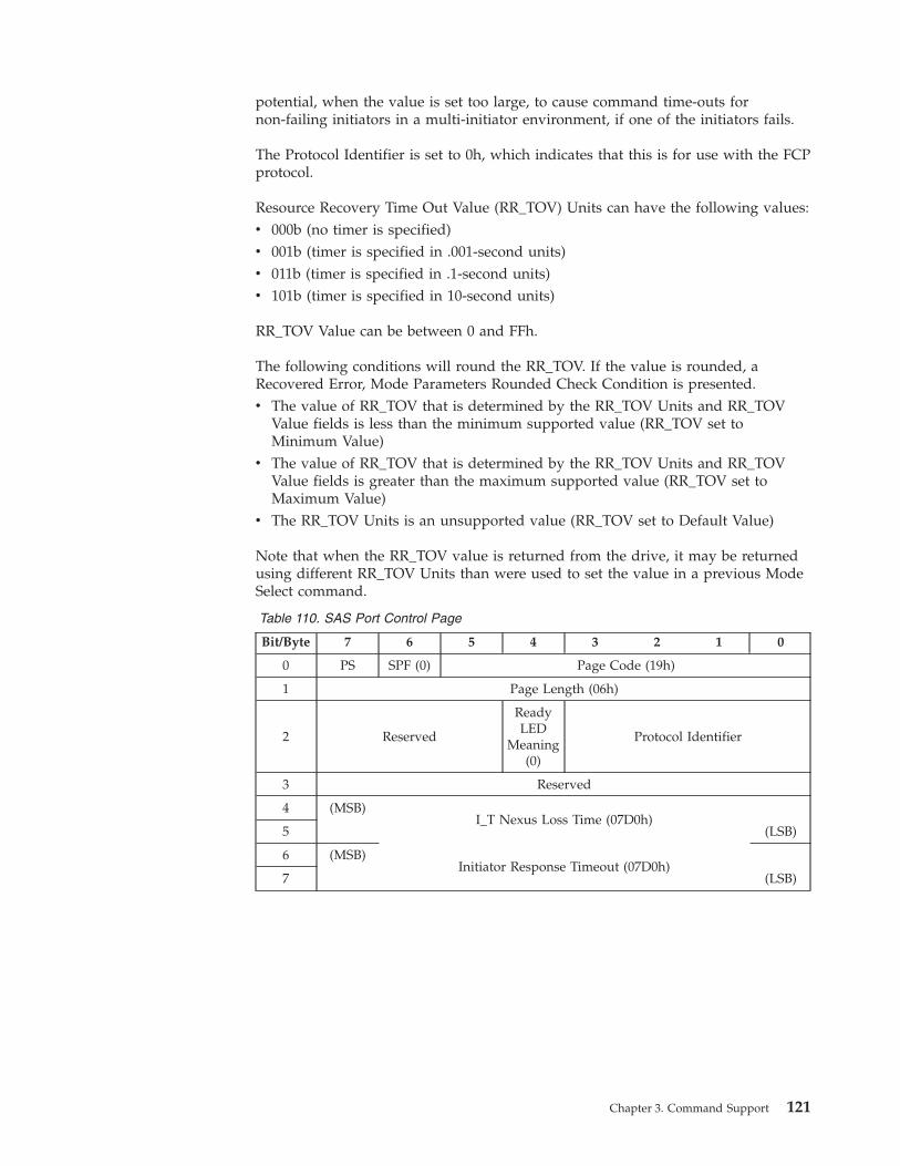
potential, when the value is set too large, to cause command time-outs for
non-failing initiators in a multi-initiator environment, if one of the initiators fails.
The Protocol Identifier is set to 0h, which indicates that this is for use with the FCP
protocol.
Resource Recovery Time Out Value (RR_TOV) Units can have the following values:
v 000b (no timer is specified)
v 001b (timer is specified in .001-second units)
v 011b (timer is specified in .1-second units)
v 101b (timer is specified in 10-second units)
RR_TOV Value can be between 0 and FFh.
The following conditions will round the RR_TOV. If the value is rounded, a
Recovered Error, Mode Parameters Rounded Check Condition is presented.
v The value of RR_TOV that is determined by the RR_TOV Units and RR_TOV
Value fields is less than the minimum supported value (RR_TOV set to
Minimum Value)
v The value of RR_TOV that is determined by the RR_TOV Units and RR_TOV
Value fields is greater than the maximum supported value (RR_TOV set to
Maximum Value)
v The RR_TOV Units is an unsupported value (RR_TOV set to Default Value)
Note that when the RR_TOV value is returned from the drive, it may be returned
using different RR_TOV Units than were used to set the value in a previous Mode
Select command.
Table 110. SAS Port Control Page
Bit/Byte 7 6 5 4 3 2 1 0
0 PS SPF (0) Page Code (19h)
1 Page Length (06h)
2 Reserved
Ready
LED
Meaning
(0)
Protocol Identifier
3 Reserved
4 (MSB)
I_T Nexus Loss Time (07D0h)
5 (LSB)
6 (MSB)
Initiator Response Timeout (07D0h)
7 (LSB)
Chapter 3. Command Support 121
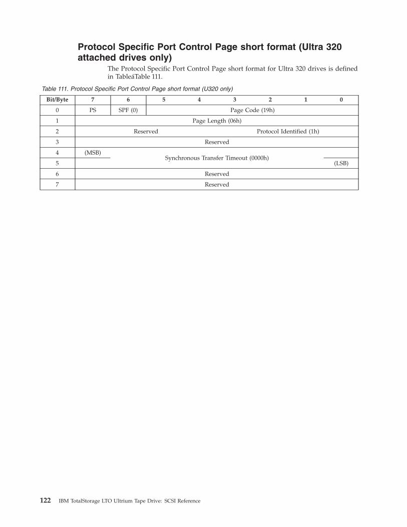
Protocol Specific Port Control Page short format (Ultra 320
attached drives only)
The Protocol Specific Port Control Page short format for Ultra 320 drives is defined
in TableáTable 111.
Table 111. Protocol Specific Port Control Page short format (U320 only)
Bit/Byte 7 6 5 4 3 2 1 0
0 PS SPF (0) Page Code (19h)
1 Page Length (06h)
2 Reserved Protocol Identified (1h)
3 Reserved
4 (MSB)
Synchronous Transfer Timeout (0000h)
5 (LSB)
6 Reserved
7 Reserved
122 IBM TotalStorage LTO Ultrium Tape Drive: SCSI Reference
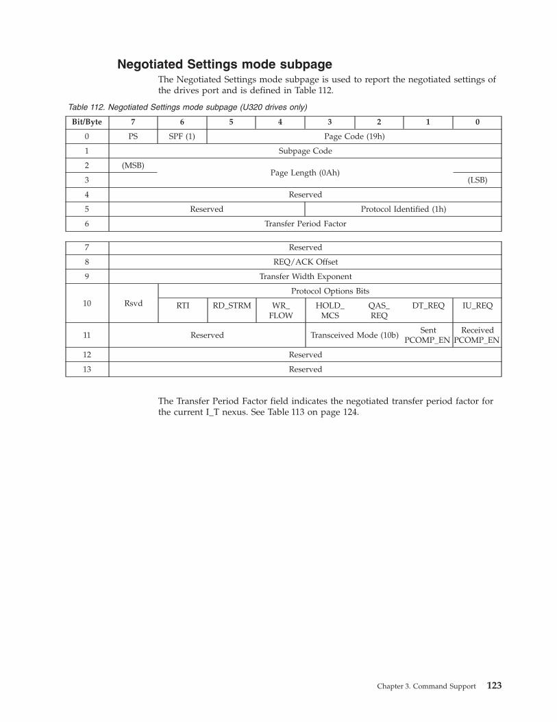
Negotiated Settings mode subpage
The Negotiated Settings mode subpage is used to report the negotiated settings of
the drives port and is defined in Table 112.
Table 112. Negotiated Settings mode subpage (U320 drives only)
Bit/Byte 7 6 5 4 3 2 1 0
0 PS SPF (1) Page Code (19h)
1 Subpage Code
2 (MSB)
Page Length (0Ah)
3 (LSB)
4 Reserved
5 Reserved Protocol Identified (1h)
6 Transfer Period Factor
7 Reserved
8 REQ/ACK Offset
9 Transfer Width Exponent
10 Rsvd
Protocol Options Bits
RTI RD_STRM WR_FLOW
HOLD_MCS
QAS_REQ
DT_REQ IU_REQ
11 Reserved Transceived Mode (10b)
Sent
PCOMP_EN
Received
PCOMP_EN
12 Reserved
13 Reserved
The Transfer Period Factor field indicates the negotiated transfer period factor for
the current I_T nexus. See Table 113 on page 124.
Chapter 3. Command Support 123

Table 113. Transfer Period Factor
Value Description Transfer Rate
00h-06h Reserved N/A
07h Transfer period equals 3.125 ns Fast-320
08h Transfer period equals 6.25 ns Fast-160
09h Transfer period equals 12.5 ns Fast-80
0Ah Transfer period equals 25 ns Fast-40
0Bh Transfer period equals 30.3 ns Fast-40
0Ch Transfer period equals 50 ns Fast-20
0Dh - 18h Transfer period equals the TRANSFER PERIOD FACTOR x 4 Fast-20
19h - 31h Transfer period equals the TRANSFER PERIOD FACTOR x 4 Fast-10
32h - FFh Transfer period equals the TRANSFER PERIOD FACTOR x 4 Fast-5
The REQ/ACK Offset field indicates the negotiated REQ/ACK offset for the
current I_T nexus
The Transfer Width Exponent field indicates the negotiated transfer width
exponent for the current I_T nexus. See Table 114
Table 114. Transfer Width Exponent
Value Description
00h Specifies 8 bit data bus (i.e., narrow transfer agreement).
01h Specifies 16 bit data bus (i.e., wide transfer agreement).
02h Obsolete
03h-FFh Reserved
The Protocol Options Bits field contain the negotiated protocol options for the
current I_T nexus.
The Received PCOMP_EN bit contains the value of the PCOMP_EN bit received
by the SCSI target port for the current I_T nexus.
The Sent PCOMP_EN bit contains the value of the PCOMP_EN bit sent by the
SCSI target port for the current I_T nexus.
124 IBM TotalStorage LTO Ultrium Tape Drive: SCSI Reference
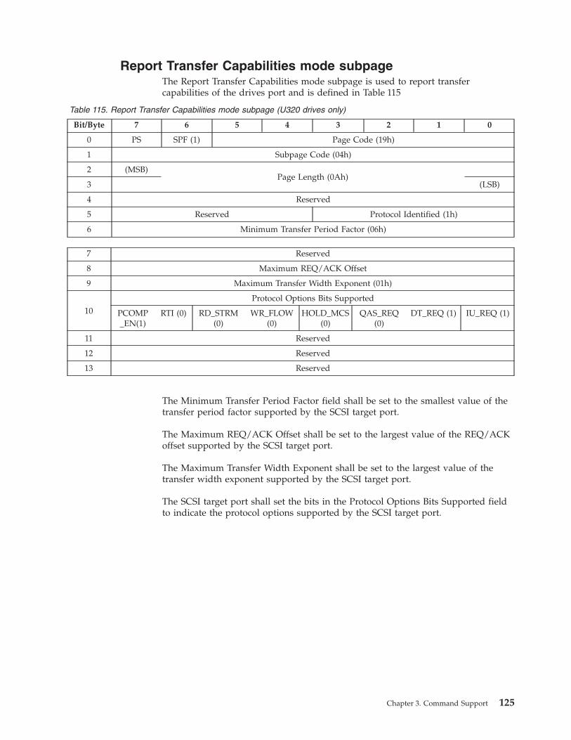
Report Transfer Capabilities mode subpage
The Report Transfer Capabilities mode subpage is used to report transfer
capabilities of the drives port and is defined in Table 115
Table 115. Report Transfer Capabilities mode subpage (U320 drives only)
Bit/Byte 7 6 5 4 3 2 1 0
0 PS SPF (1) Page Code (19h)
1 Subpage Code (04h)
2 (MSB)
Page Length (0Ah)
3 (LSB)
4 Reserved
5 Reserved Protocol Identified (1h)
6 Minimum Transfer Period Factor (06h)
7 Reserved
8 Maximum REQ/ACK Offset
9 Maximum Transfer Width Exponent (01h)
10
Protocol Options Bits Supported
PCOMP_EN(1)
RTI (0) RD_STRM
(0)
WR_FLOW(0)
HOLD_MCS(0)
QAS_REQ(0)
DT_REQ (1) IU_REQ (1)
11 Reserved
12 Reserved
13 Reserved
The Minimum Transfer Period Factor field shall be set to the smallest value of the
transfer period factor supported by the SCSI target port.
The Maximum REQ/ACK Offset shall be set to the largest value of the REQ/ACK
offset supported by the SCSI target port.
The Maximum Transfer Width Exponent shall be set to the largest value of the
transfer width exponent supported by the SCSI target port.
The SCSI target port shall set the bits in the Protocol Options Bits Supported field
to indicate the protocol options supported by the SCSI target port.
Chapter 3. Command Support 125

Mode Page 1Ch: Information Exceptions Mode Page
Table 116. Information Exceptions Mode Page
Byte
Bit
7 6 5 4 3 2 1 0
0 PS (0) Reserved Page Code (1Ch)
1 Page Length (0A)
2 Perf (0) Reserved DExcpt Test Reserved LogErr(0)
3 Reserved MRIE (3)
4
:
7
Interval Timer (0)
8
:
11
Report Count (0)
The Information Exceptions mode page is used to control Exception Reporting by
using the TapeAlert log page.
A disable exception control (DExcpt) field of 0 indicates that reporting for failure
prediction threshold exceeded will be enabled. The method for reporting the failure
prediction threshold exceeded when the DExcpt field is set to 0 is determined from
the MRIE field. A DExcpt field of 1 indicates that the target will disable reporting
of the failure prediction threshold exceeded. The default value for DExcpt is 0.
If the Test field is set to 1, the next command will fail, the Sense Key will be set to
Unit Attention, and the ASC/ASCQ will be set to Failure Prediction Threshold
Exceeded - False (5DFF). If the Test field is set to 0, the next command is processed
normally. The default for Test is 0.
The Perf and LogErr fields will be 0. These features are not supported.
The MRIE field must be set to 3 (Conditionally generate recovered error). This
method instructs the drive to report informational exception conditions (if the
reporting of recovered errors is allowed) by returning a Check Condition status. If
the Test field is set to 0, the status may be returned after the informational
exception condition occurs on any command for which Good status would have
been returned. If the Test field is set to 1, the status will be returned on the next
command that is normally capable of returning an informational exception
condition when the Test field is set to 0. The Sense Key must be set to Recovered
Error and the Additional Sense Code will indicate the cause of the informational
exception condition. This will be Failure Prediction Threshold Exceeded (5D00) if
the Test field is set to 0 (true error), and Failure Prediction Threshold Exceeded
-False (5DFF) if the Test field is set to 1 (test).
The command that returns the Check Condition status for the informational
exception will complete without error before any informational exception condition
may be reported. The Interval Timer and Report Count must be set to 0. These
fields are not supported.
126 IBM TotalStorage LTO Ultrium Tape Drive: SCSI Reference

Mode Page 1Dh: Medium Configuration Mode Page
The Medium Configuration Mode Page (see Table 117) specifies any special
considerations the drive will use when processing commands when there is a
WORM medium loaded in the drive. This page is supported only on Ultrium 3
drives. This page is returned when requested by a Mode Sense command
indicating either this page or all pages (3Fh).
Table 117. Medium Configuration Mode Page
Byte
Bit
7 6 5 4 3 2 1 0
0 PS (0) SPF(0) Page Code (1Dh)
1 Page Length (1Eh)
2 Reserved WORMM
3 Reserved
4 Worm Mode Label Restrictions (01h)
5 Worm Mode Filemark Restrictions (02h)
6-31 Reserved
The WORMM bit is set to 1 when the drive is operating in WORM mode. The
WORMM bit is set to 0 when the drive is not operating in WORM mode. If a
Mode Select command is processed that attempts to change the setting of the
WORMM bit, the drive returns a Check Condition status, with the sense key set to
Illegal Request, and the addition sense code set to Invalid Field In Parameter List.
The Worm Model Label Restrictions field specifies the restrictions against
overwriting format labels when operating in WORM mode (see Table 118).
A series of filemarks with no interleaved logical blocks immediately preceding
EOD is treated as a filemark sequence and controlled by the Worm Mode
Filemarks Restrictions field.
Table 118. Worm Mode Label Restrictions field values
Worm ModeLabel Restrictions
Description
00h The drive does not allow any logical blocks to be overwritten. (Not Supported)
01h
The drive allows a tape header to be overwritten. The tape header is defined as 0, 1,
or 2 logical blocks followed by nothing except 0 to n Filemarks and EOD. This must
be overwritten from BOP.
02h The drive allows all format labels to be overwritten. (Not Supported)
03h - FFh Reserved
The Worm Mode Filemarks Restrictions field specifies the restrictions against
overwriting a series of filemarks immediately preceding EOD when operating in
WORM mode (see Table 119 on page 128). This field controls only the overwriting
of a series of filemarks with no interleaved logical blocks immediately preceding
EOD.
Chapter 3. Command Support 127
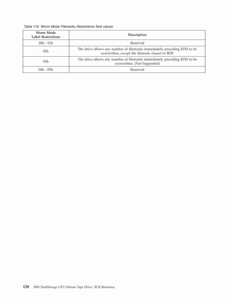
Table 119. Worm Mode Filemarks Restrictions field values
Worm ModeLabel Restrictions
Description
00h - 01h Reserved
02h
The drive allows any number of filemarks immediately preceding EOD to be
overwritten, except the filemark closest to BOP.
03h
The drive allows any number of filemarks immediately preceding EOD to be
overwritten. (Not Supported)
04h - FFh Reserved
128 IBM TotalStorage LTO Ultrium Tape Drive: SCSI Reference
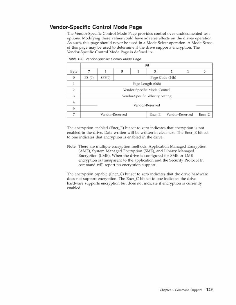
Vendor-Specific Control Mode Page
The Vendor-Specific Control Mode Page provides control over undocumented test
options. Modifying these values could have adverse effects on the drives operation.
As such, this page should never be used in a Mode Select operation. A Mode Sense
of this page may be used to determine if the drive supports encryption. The
Vendor-Specific Control Mode Page is defined in .
Table 120. Vendor-Specific Control Mode Page
Byte
Bit
7 6 5 4 3 2 1 0
0 PS (0) SPF(0) Page Code (24h)
1 Page Length (06h)
2 Vendor-Specific Mode Control
3 Vendor-Specific Velocity Setting
4
Vendor-Reserved
6
7 Vendor-Reserved Encr_E Vendor-Reserved Encr_C
The encryption enabled (Encr_E) bit set to zero indicates that encryption is not
enabled in the drive. Data written will be written in clear text. The Encr_E bit set
to one indicates that encryption is enabled in the drive.
Note: There are multiple encryption methods, Application Managed Encryption
(AME), System Managed Encryption (SME), and Library Managed
Encryption (LME). When the drive is configured for SME or LME
encryption is transparent to the application and the Security Protocol In
command will report no encryption support.
The encryption capable (Encr_C) bit set to zero indicates that the drive hardware
does not support encryption. The Encr_C bit set to one indicates the drive
hardware supports encryption but does not indicate if encryption is currently
enabled.
Chapter 3. Command Support 129

28-31 Vendor-Reserved
130 IBM TotalStorage LTO Ultrium Tape Drive: SCSI Reference

Mode Page 2Fh: Behavior Configuration Mode Page
There is one copy of this page for the drive.
Ultrium drive support for the fields in this page vary by generation and/or code
level. To discover if a field can be modified, issue a Mode Sense with a PC field of
01 to see if the field is changeable. This will also return the Page Length, which
must be examined to determined the length of this page, because it is expected to
increase as additional Behavior configurations are added to subsequent code levels.
WARNING: This page changes the normal behavior of the drive. Some settings
effect error reporting and may even cause the drive to violate SCSI standards. Care
should be taken to ensure that the behavior change is understood and what its
effects on the system will be.
Table 121. Behavior Configuration Mode Page
Byte
Bit
7 6 5 4 3 2 1 0
0 PS Reserved Page Code (2Fh)
1 Page Length (n-1)
2 Fence Behavior
3 Clean Behavior
4 "Emulate WORM"
... Sense Data Behavior
5 Reporting Behavior
6 Rsvd Rsvd Rsvd Rsvd Rsvd CCDM DDEOR CLNCHK
.
.
.
A Check Condition for Dead Media (CCDM) bit set to one specifies that a Check Condition, Sense Key =
1h, ASC/ASCQ 8252h (Degraded Media) will be returned after a Rewind command when the criteria are
met to set the Dead Media flag in Log Page 3Ch. A CCDM bit set to zero does not specify that a Check
Condition will be returned when the Dead Media criteria are met. The default value of this bit is zero
(default is one if manufactured as an eServer drive).
n Reserved for Future Use
8
Unload On Error Behavior
Reserved UOE-C UOE-F UOE-D
.
.
.
n Reserved for Future Use
Fence Behavior (Byte 2)
This field defines drive behavior in situations deemed dangerous for either media
or data on the media.
Table 122. Fence Behavior Selection Values
Description Value
Normal Operation (default)Mid-Tape Recovery (MTR) Fence Only
00h
Panic Fence Feature Enabled 01h
Reserved 02h - FFh
Chapter 3. Command Support 131

Normal Operation (0): The behavior of the drive after a Panic or Exception when
in normal operation is defined below).
When the drive comes up after a Panic or Exception and no cartridge is detected,
the drive will respond to SCSI commands as follows (Steps 1 and 2 are returned in
response to any check condition eligible command):
1. 6/2900 sense is returned.
2. 2/3e00 is returned during POST.
3. When POST completes, enter normal operation.
When the drive comes up and detects a cartridge, it requires Mid-Tape Recovery
(MTR) and will responsd to SCSI commands as follows (Steps 1 through 5 are
returned in response to any check condition eligible command):
1. 6/2900 is returned.
2. 2/3e00 is returned during POST.
3. 2/0400 is returned during Mid-Tape Recovery/Unload.
4. 2/0401 is returned during Mid_Tape Recovery/Load.
5. 6/2800 is returned after cartridge is loaded.
6. Enter into the MTR Fence State.
a. TUR commands will return GOOD status.
b. Return 5/2C00 Sense for all medium access commands.
c. Exit MTR Fence State when an explicit positioning command completes
successfully (that is, Locate, Rewind, Load).
Panic Fence Feature Enabled (01h): The behavior of the drive after the Panic or
Exception when the Panic Fence Feature is enabled is defined below.
When the drive comes up after a Panic of Exception and no cartridge is detected,
the drive will respond to SCSI commands as follows (Steps 1 and 2 are returned in
response to any check condition eligible command):
1. 6/2900 sense is returned.
2. 2/3e00 is returned during POST.
3. When POST completes, enter into the Panic Fence state. In the Panic Fence
state:
a. SCSI commands other than RSNS/INQ/RLUNs/Read Buffer/TUR are
rejected with 5/2904 sense, indicating Panic Fence state.
b. TUR commands will return 5/2904 sense.
c. Load of a cartridge through any means is not allowed.
d. SCSI Read Buffer to read dump data is accepted at any time.
e. Once dump has been read, go to normal mode.
When the drive comes up and detects Mid-Tape Recovery (MTR), it will respond
to SCSI commands as follows (steps 1 through 5 are returned in response to any
check condition eligible command):
1. 6/2900 sense is returned.
2. 2/3e00 is returned during POST.
3. 2/0400 is returned during Mid-Tape Recovery/Unload.
4. 2/0401 is returned during Mid-Tape Recovery/Load.
5. 6/2800 is returned after cartridge is loaded.
6. Enter into the Panic Fence state.
132 IBM TotalStorage LTO Ultrium Tape Drive: SCSI Reference

a. SCSI commands other than RSNS/INQ/RLUNs/Read Buffer/TUR/Load
with the load bit set to 0 are rejected with 5/2904 sense, indicating Panic
Fence state.
b. TUR commands will return GOOD status while tape is loaded.
c. TUR commands will return 5/2904 sense after the tape is unloaded.
d. Unload command through SCSI/LDI/Button can be executed anytime.
e. Load of a cartridge through any means is not allowed.
f. SCSI Read Buffer to read dump data is accepted at any time.
g. Once dump has been read, if the tape is still loaded, transition to MTR
Fence state. If tape is still not loaded, exit from Panic Fence state and go to
normal mode.7. MTR Fence state.
a. TUR commands will return GOOD status.
b. Return 5/2C00 Sense for all medium access commands.
c. Exit MTR Fence State when an explicit positioning command completes
successfully (that is, Locate, Rewind, Load).
After description of Firmware Update Behavior (i.e. at the end of the Behavior
Configuration Mode Page description) add the following subsection:
v Bad Media causes a mount failure;
v FMR cartridge is loaded when it has not been requested;
v Expired cleaner cartridge is loaded; or
v An invalid or unsupported cleaner cartridge is loaded.
Clean Behavior (Byte 3)
This field defines the behavior of the drive related to cleaning.
Description Value
Normal Operation (default) 00h
Periodic Clean Notification Enabled 01h
Reserved 02h - FFh
Periodic Clean Notification Enabled (01h): The drive shall monitor the number of
write and read datasets since last cleaning. When the number of write/read
datasets exceeds the criteria the drive will put itself in a clean notification needed
state. The criteria used is subject to change, but the current criteria is listed in
Table 123.
Table 123. Periodic Clean Notification Usage Criteria
Generation Drive Data Sets Processed
Equivalent Full File
Passes
(Approximate)
Meters of tape
pulled accross head
Ultrium 1 10,000,000 38 N/A
Ultrium 2 10,000,000 19 N/A
Ultrium 3 10,000,000 38 N/A
Ultrium 4 12,000,000 23 5,000,000
Chapter 3. Command Support 133
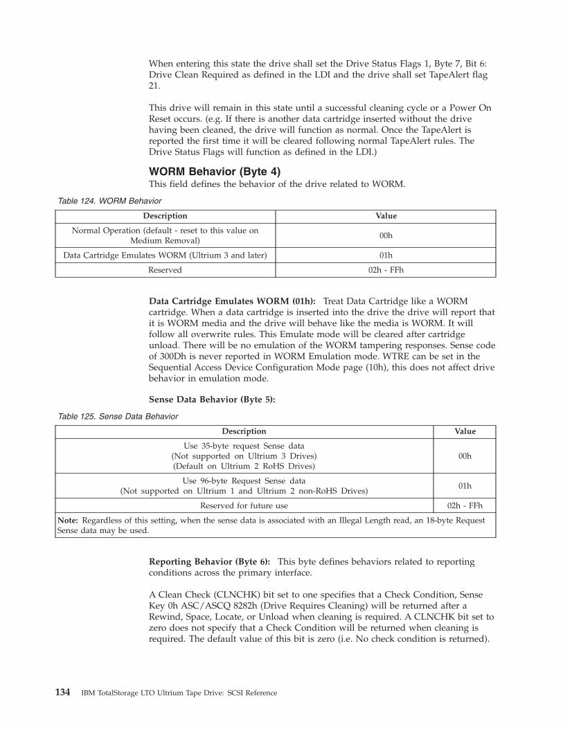
When entering this state the drive shall set the Drive Status Flags 1, Byte 7, Bit 6:
Drive Clean Required as defined in the LDI and the drive shall set TapeAlert flag
21.
This drive will remain in this state until a successful cleaning cycle or a Power On
Reset occurs. (e.g. If there is another data cartridge inserted without the drive
having been cleaned, the drive will function as normal. Once the TapeAlert is
reported the first time it will be cleared following normal TapeAlert rules. The
Drive Status Flags will function as defined in the LDI.)
WORM Behavior (Byte 4)
This field defines the behavior of the drive related to WORM.
Table 124. WORM Behavior
Description Value
Normal Operation (default - reset to this value on
Medium Removal)
00h
Data Cartridge Emulates WORM (Ultrium 3 and later) 01h
Reserved 02h - FFh
Data Cartridge Emulates WORM (01h): Treat Data Cartridge like a WORM
cartridge. When a data cartridge is inserted into the drive the drive will report that
it is WORM media and the drive will behave like the media is WORM. It will
follow all overwrite rules. This Emulate mode will be cleared after cartridge
unload. There will be no emulation of the WORM tampering responses. Sense code
of 300Dh is never reported in WORM Emulation mode. WTRE can be set in the
Sequential Access Device Configuration Mode page (10h), this does not affect drive
behavior in emulation mode.
Sense Data Behavior (Byte 5):
Table 125. Sense Data Behavior
Description Value
Use 35-byte request Sense data
(Not supported on Ultrium 3 Drives)
(Default on Ultrium 2 RoHS Drives)
00h
Use 96-byte Request Sense data
(Not supported on Ultrium 1 and Ultrium 2 non-RoHS Drives)
01h
Reserved for future use 02h - FFh
Note: Regardless of this setting, when the sense data is associated with an Illegal Length read, an 18-byte Request
Sense data may be used.
Reporting Behavior (Byte 6): This byte defines behaviors related to reporting
conditions across the primary interface.
A Clean Check (CLNCHK) bit set to one specifies that a Check Condition, Sense
Key 0h ASC/ASCQ 8282h (Drive Requires Cleaning) will be returned after a
Rewind, Space, Locate, or Unload when cleaning is required. A CLNCHK bit set to
zero does not specify that a Check Condition will be returned when cleaning is
required. The default value of this bit is zero (i.e. No check condition is returned).
134 IBM TotalStorage LTO Ultrium Tape Drive: SCSI Reference
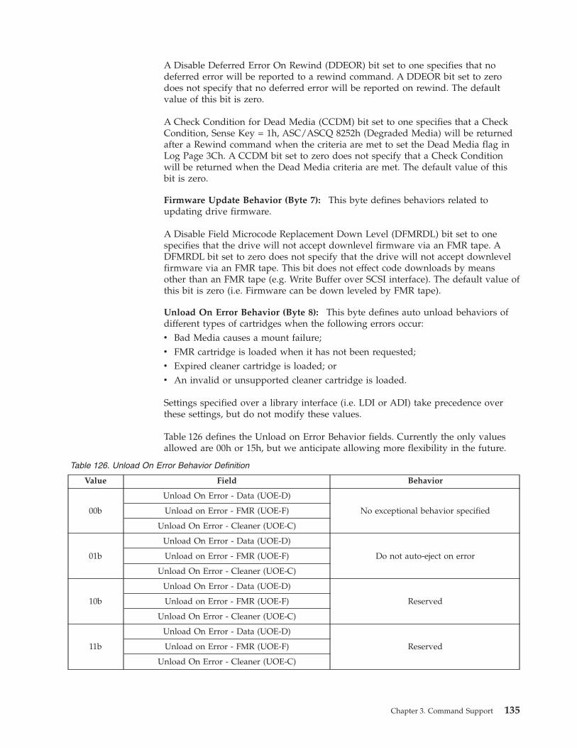
A Disable Deferred Error On Rewind (DDEOR) bit set to one specifies that no
deferred error will be reported to a rewind command. A DDEOR bit set to zero
does not specify that no deferred error will be reported on rewind. The default
value of this bit is zero.
A Check Condition for Dead Media (CCDM) bit set to one specifies that a Check
Condition, Sense Key = 1h, ASC/ASCQ 8252h (Degraded Media) will be returned
after a Rewind command when the criteria are met to set the Dead Media flag in
Log Page 3Ch. A CCDM bit set to zero does not specify that a Check Condition
will be returned when the Dead Media criteria are met. The default value of this
bit is zero.
Firmware Update Behavior (Byte 7): This byte defines behaviors related to
updating drive firmware.
A Disable Field Microcode Replacement Down Level (DFMRDL) bit set to one
specifies that the drive will not accept downlevel firmware via an FMR tape. A
DFMRDL bit set to zero does not specify that the drive will not accept downlevel
firmware via an FMR tape. This bit does not effect code downloads by means
other than an FMR tape (e.g. Write Buffer over SCSI interface). The default value of
this bit is zero (i.e. Firmware can be down leveled by FMR tape).
Unload On Error Behavior (Byte 8): This byte defines auto unload behaviors of
different types of cartridges when the following errors occur:
v Bad Media causes a mount failure;
v FMR cartridge is loaded when it has not been requested;
v Expired cleaner cartridge is loaded; or
v An invalid or unsupported cleaner cartridge is loaded.
Settings specified over a library interface (i.e. LDI or ADI) take precedence over
these settings, but do not modify these values.
Table 126 defines the Unload on Error Behavior fields. Currently the only values
allowed are 00h or 15h, but we anticipate allowing more flexibility in the future.
Table 126. Unload On Error Behavior Definition
Value Field Behavior
00b
Unload On Error - Data (UOE-D)
No exceptional behavior specified Unload on Error - FMR (UOE-F)
Unload On Error - Cleaner (UOE-C)
01b
Unload On Error - Data (UOE-D)
Do not auto-eject on error Unload on Error - FMR (UOE-F)
Unload On Error - Cleaner (UOE-C)
10b
Unload On Error - Data (UOE-D)
Reserved Unload on Error - FMR (UOE-F)
Unload On Error - Cleaner (UOE-C)
11b
Unload On Error - Data (UOE-D)
Reserved Unload on Error - FMR (UOE-F)
Unload On Error - Cleaner (UOE-C)
Chapter 3. Command Support 135
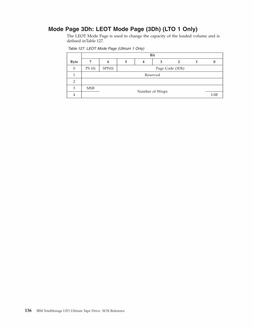
Mode Page 3Dh: LEOT Mode Page (3Dh) (LTO 1 Only)
The LEOT Mode Page is used to change the capacity of the loaded volume and is
defined inTable 127.
Table 127. LEOT Mode Page (Ultrium 1 Only)
Byte
Bit
7 6 5 4 3 2 1 0
0 PS (0) SPF(0) Page Code (3Dh)
1 Reserved
2
3 MSB
Number of Wraps
4 LSB
136 IBM TotalStorage LTO Ultrium Tape Drive: SCSI Reference
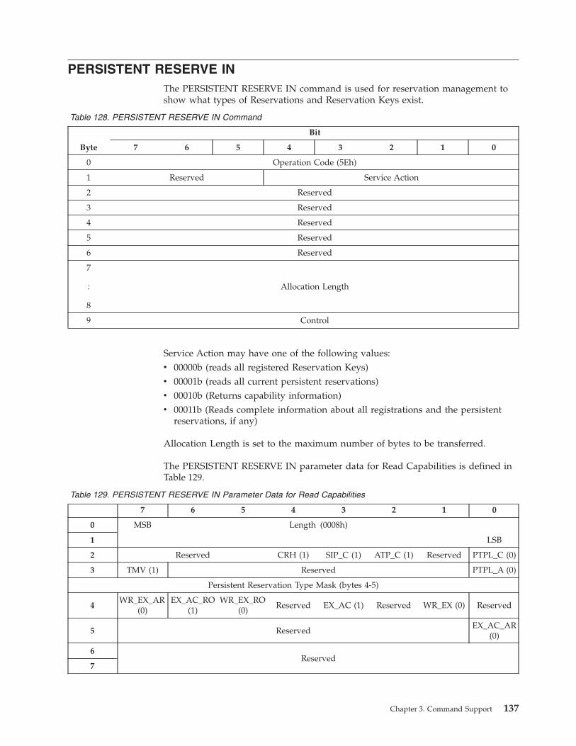
PERSISTENT RESERVE IN
The PERSISTENT RESERVE IN command is used for reservation management to
show what types of Reservations and Reservation Keys exist.
Table 128. PERSISTENT RESERVE IN Command
Byte
Bit
7 6 5 4 3 2 1 0
0 Operation Code (5Eh)
1 Reserved Service Action
2 Reserved
3 Reserved
4 Reserved
5 Reserved
6 Reserved
7
:
8
Allocation Length
9 Control
Service Action may have one of the following values:
v 00000b (reads all registered Reservation Keys)
v 00001b (reads all current persistent reservations)
v 00010b (Returns capability information)
v 00011b (Reads complete information about all registrations and the persistent
reservations, if any)
Allocation Length is set to the maximum number of bytes to be transferred.
The PERSISTENT RESERVE IN parameter data for Read Capabilities is defined in
Table 129.
Table 129. PERSISTENT RESERVE IN Parameter Data for Read Capabilities
7 6 5 4 3 2 1 0
0 MSB Length (0008h)
1 LSB
2 Reserved CRH (1) SIP_C (1) ATP_C (1) Reserved PTPL_C (0)
3 TMV (1) Reserved PTPL_A (0)
Persistent Reservation Type Mask (bytes 4-5)
4
WR_EX_AR
(0)
EX_AC_RO
(1)
WR_EX_RO
(0)
Reserved EX_AC (1) Reserved WR_EX (0) Reserved
5 Reserved
EX_AC_AR
(0)
6
Reserved
7
Chapter 3. Command Support 137
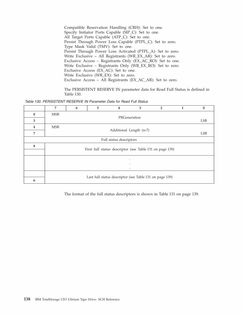
Compatible Reservation Handling (CRH): Set to one.
Specify Initiator Ports Capable (SIP_C): Set to one.
All Target Ports Capable (ATP_C): Set to one.
Persist Through Power Loss Capable (PTPL_C): Set to zero.
Type Mask Valid (TMV): Set to one.
Persist Through Power Loss Activated (PTPL_A): Set to zero.
Write Exclusive – All Registrants (WR_EX_AR): Set to zero.
Exclusive Access – Registrants Only (EX_AC_RO): Set to one.
Write Exclusive – Registrants Only (WR_EX_RO): Set to zero.
Exclusive Access (EX_AC): Set to one.
Write Exclusive (WR_EX): Set to zero.
Exclusive Access – All Registrants (EX_AC_AR): Set to zero.
The PERSISTENT RESERVE IN parameter data for Read Full Status is defined in
Table 130.
Table 130. PERSISTENT RESERVE IN Parameter Data for Read Full Status
7 6 5 4 3 2 1 0
0 MSB
PRGeneration
3 LSB
4 MSB
Additional Length (n-7)
7 LSB
Full status descriptors
8
First full status descriptor (see Table 131 on page 139)
.
.
.
Last full status descriptor (see Table 131 on page 139)
n
The format of the full status descriptors is shown in Table 131 on page 139.
138 IBM TotalStorage LTO Ultrium Tape Drive: SCSI Reference

Table 131. PERSISTENT RESERVE IN Full Status descriptor format
7 6 5 4 3 2 1 0
0 MSB
Reservation Key
7 LSB
8 MSB
Reserved
11
12 Reserved ALL_TG_PT R_HOLDER
13 SCOPE TYPE
14
Reserved
17
18 MSB
Relative Target Port Identifier
19 LSB
20 MSB
Additional Desscriptor Length (n-23)
23 LSB
24
TransportID
n
Reservation Holder (R_HOLDER).
All Target Ports (ALL_TG_PT).
The PERSISTENT RESERVE IN parameter data for Read Keys is defined in
Table 132.
Table 132. PERSISTENT RESERVE IN Parameter Data for Read Keys
Byte
Bit
7 6 5 4 3 2 1 0
0
:
3
Generation
4
:
7
Additional Length
8
:
15
First Reservation Key
16
:
n
Additional Reservation Keys
Generation is a counter for PERSISTENT RESERVE OUT command requests.
Additional Length is a count of the number of bytes in the Reservation Key list.
Chapter 3. Command Support 139
For Additional Reservation Keys, a maximum of one reservation key per initiator
is supported.
The PERSISTENT RESERVE IN parameter data for Read Reservations is defined in
Table 133.
Table 133. PERSISTENT RESERVE IN Parameter Data for Read Reservations
Byte
Bit
7 6 5 4 3 2 1 0
0
:
3
Generation
4
:
7
Additional Length
8
:
n
Read Reservations Descriptor
Generation is a counter for PERSISTENT RESERVE OUT command requests.
Additional Length is a count of the number of bytes in the Reservation Key list.
Reservation Descriptors are defined in Table 134.
The PERSISTENT RESERVE IN Read Reservations Descriptor is defined in
Table 134.
Table 134. PERSISTENT RESERVE IN Read Reservations Descriptor
Byte
Bit
7 6 5 4 3 2 1 0
0
:
7
Reservation Key
8
:
11
Scope-specific address (0)
12 Reserved
13 Scope (0h) Type
14
:
15
Extent Length (0)
140 IBM TotalStorage LTO Ultrium Tape Drive: SCSI Reference
A Scope value of 0h indicates that the persistent reservation applies to the entire
logical unit.
Type may have one of the following values:
v 3h means Exclusive Access
v 6h means Exclusive Access, Registrants only
Chapter 3. Command Support 141

PERSISTENT RESERVE OUT
The PERSISTENT RESERVE OUT command is used for reservation management to
allow different types of Reservations and Reservation Keys to be created or
removed.
Table 135. PERSISTENT RESERVE OUT Command
Byte
Bit
7 6 5 4 3 2 1 0
0 Operation Code (5Fh)
1 Reserved Service Action
2 Scope ( 0) Type
3 Reserved
4 Reserved
5 Reserved
6 Reserved
7
:
8
Parameter List Length (18h)
9 Control
Table 136 contains the values for Service Action field. For additional information
about the descriptions of each service action code, refer to the SCSI Primary
Commands-3 (SPC-3) manual.
Table 136. Values for Service Action Codes in PERSISTENT RESERVE OUT Command
Code Name Description
PERSISTENT
RESERVE Generation
Field Incremented
00h REGISTER
Registers a reservation key with the device
server or unregisters a reservation key.
Yes
01h RESERVE
Creates a persistent reservation that has a
specified SCOPE and TYPE.
No
02h RELEASE Releases the selected persistent reservation. No
03h CLEAR
Clears all reservation keys (for example,
registrations) and all persistent reservations.
Yes
04h PREEMPT
Preempts persistent reservations or removes
registrations.
Yes
05h
PREEMPT AND
ABORT
Preempts persistent reservations or removes
registrations and aborts all tasks for all
preempted initiator ports.
Yes
06h
REGISTER AND
IGNORE EXISTING
KEY
Registers a reservation key with the device
server or unregisters a reservation key.
Yes
07h
REGISTER AND
MOVE
Register a reservation key for another I_T
nexus with the device server and move
apersistent reservation to that I_T nexus
Yes
08h - 1Fh Reserved
142 IBM TotalStorage LTO Ultrium Tape Drive: SCSI Reference
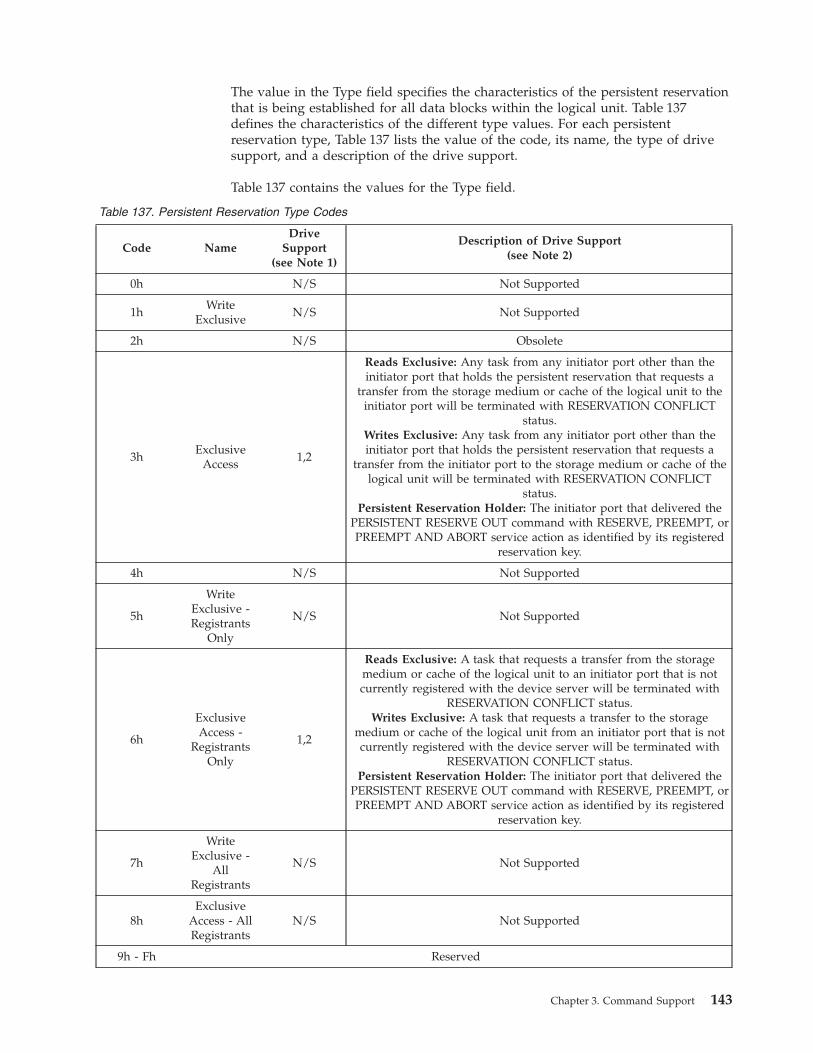
The value in the Type field specifies the characteristics of the persistent reservation
that is being established for all data blocks within the logical unit. Table 137
defines the characteristics of the different type values. For each persistent
reservation type, Table 137 lists the value of the code, its name, the type of drive
support, and a description of the drive support.
Table 137 contains the values for the Type field.
Table 137. Persistent Reservation Type Codes
Code Name
Drive
Support(see Note 1)
Description of Drive Support(see Note 2)
0h N/S Not Supported
1h
Write
Exclusive
N/S Not Supported
2h N/S Obsolete
3h
Exclusive
Access
1,2
Reads Exclusive: Any task from any initiator port other than the
initiator port that holds the persistent reservation that requests a
transfer from the storage medium or cache of the logical unit to the
initiator port will be terminated with RESERVATION CONFLICT
status.Writes Exclusive: Any task from any initiator port other than the
initiator port that holds the persistent reservation that requests a
transfer from the initiator port to the storage medium or cache of the
logical unit will be terminated with RESERVATION CONFLICT
status.Persistent Reservation Holder: The initiator port that delivered the
PERSISTENT RESERVE OUT command with RESERVE, PREEMPT, or
PREEMPT AND ABORT service action as identified by its registered
reservation key.
4h N/S Not Supported
5h
Write
Exclusive -
Registrants
Only
N/S Not Supported
6h
Exclusive
Access -
Registrants
Only
1,2
Reads Exclusive: A task that requests a transfer from the storage
medium or cache of the logical unit to an initiator port that is not
currently registered with the device server will be terminated with
RESERVATION CONFLICT status.Writes Exclusive: A task that requests a transfer to the storage
medium or cache of the logical unit from an initiator port that is not
currently registered with the device server will be terminated with
RESERVATION CONFLICT status.Persistent Reservation Holder: The initiator port that delivered the
PERSISTENT RESERVE OUT command with RESERVE, PREEMPT, or
PREEMPT AND ABORT service action as identified by its registered
reservation key.
7h
Write
Exclusive -
All
Registrants
N/S Not Supported
8h
Exclusive
Access - All
Registrants
N/S Not Supported
9h - Fh Reserved
Chapter 3. Command Support 143
Table 137. Persistent Reservation Type Codes (continued)
Code Name
Drive
Support(see Note 1)
Description of Drive Support(see Note 2)
Notes:
1. Drive Support is categorized as follows:
1 = Generation 1
2 = Generation 2
N/S = not supported
2. The Description of Drive Support column is divided into three categories:
A definition of the required handling for read operations.
A definition of the required handling for write operations.
A definition of the persistent reservation holder (for more information, refer to the SCSI Primary Commands-3
(SPC-3) manual.
The PERSISTENT RESERVE OUT parameter list for all service actions except
REGISTER AND MOVE (07h) is defined in Table 138.
Table 138. PERSISTENT RESERVE OUT Parameter List
Byte
Bit
7 6 5 4 3 2 1 0
0
:
7
Reservation Key
8
:
15
Service Action Reservation Key
16
:
19
Scope-specific Address (0)
20 Reserved APTPL (0)
21 Reserved
22
:
23
Obsolete (0)
Any value is allowed for the Reservation Key and the Service Action Reservation
Key.
The value for Activate Persist Through Power Loss (APTPL) will be 0.
The PERSISTENT RESERVE OUT parameter list for REGISTER AND MOVE (07h)
is defined in Table 139 on page 145.
144 IBM TotalStorage LTO Ultrium Tape Drive: SCSI Reference
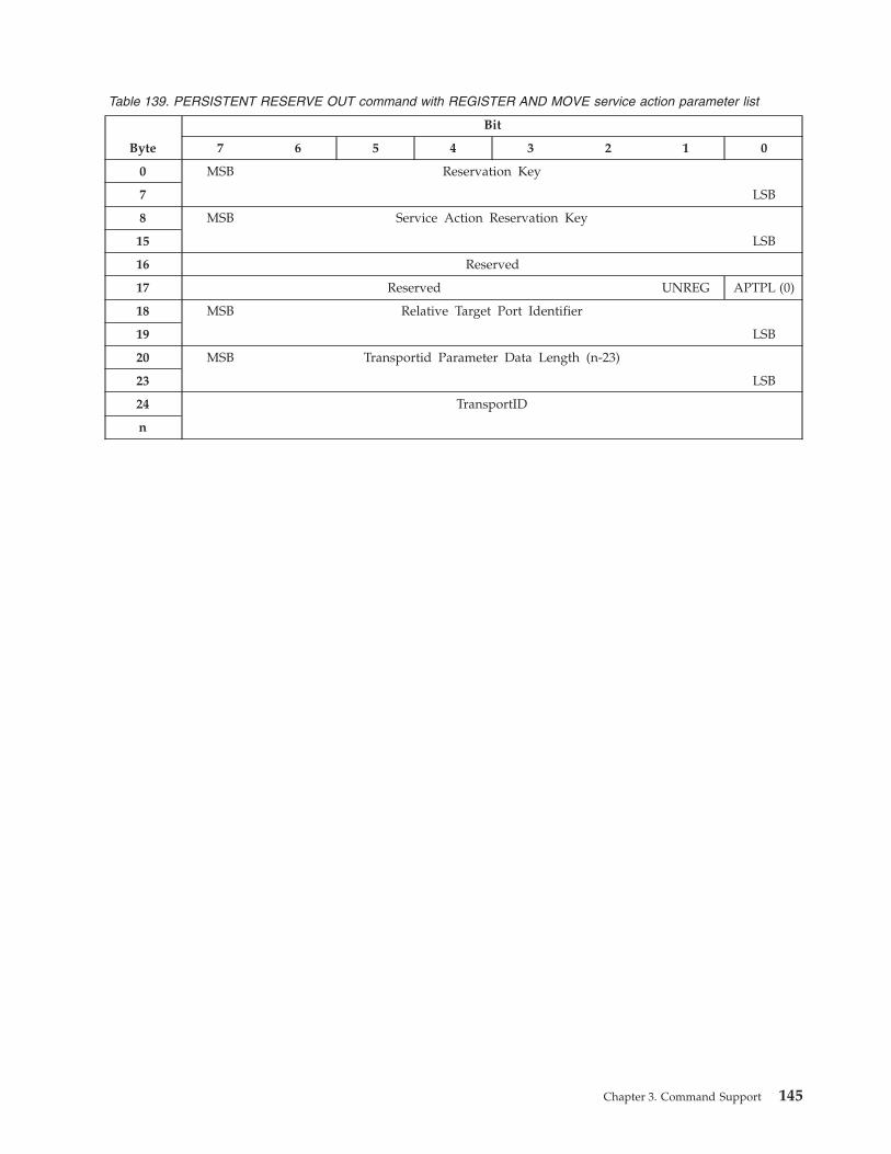
Table 139. PERSISTENT RESERVE OUT command with REGISTER AND MOVE service action parameter list
Byte
Bit
7 6 5 4 3 2 1 0
0 MSB Reservation Key
7 LSB
8 MSB Service Action Reservation Key
15 LSB
16 Reserved
17 Reserved UNREG APTPL (0)
18 MSB Relative Target Port Identifier
19 LSB
20 MSB Transportid Parameter Data Length (n-23)
23 LSB
24 TransportID
n
Chapter 3. Command Support 145
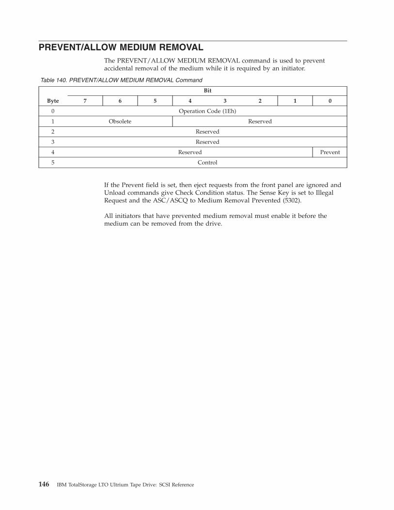
PREVENT/ALLOW MEDIUM REMOVAL
The PREVENT/ALLOW MEDIUM REMOVAL command is used to prevent
accidental removal of the medium while it is required by an initiator.
Table 140. PREVENT/ALLOW MEDIUM REMOVAL Command
Byte
Bit
7 6 5 4 3 2 1 0
0 Operation Code (1Eh)
1 Obsolete Reserved
2 Reserved
3 Reserved
4 Reserved Prevent
5 Control
If the Prevent field is set, then eject requests from the front panel are ignored and
Unload commands give Check Condition status. The Sense Key is set to Illegal
Request and the ASC/ASCQ to Medium Removal Prevented (5302).
All initiators that have prevented medium removal must enable it before the
medium can be removed from the drive.
146 IBM TotalStorage LTO Ultrium Tape Drive: SCSI Reference
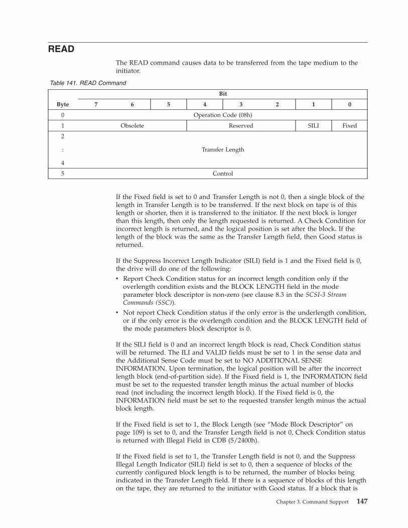
READ
The READ command causes data to be transferred from the tape medium to the
initiator.
Table 141. READ Command
Byte
Bit
7 6 5 4 3 2 1 0
0 Operation Code (08h)
1 Obsolete Reserved SILI Fixed
2
:
4
Transfer Length
5 Control
If the Fixed field is set to 0 and Transfer Length is not 0, then a single block of the
length in Transfer Length is to be transferred. If the next block on tape is of this
length or shorter, then it is transferred to the initiator. If the next block is longer
than this length, then only the length requested is returned. A Check Condition for
incorrect length is returned, and the logical position is set after the block. If the
length of the block was the same as the Transfer Length field, then Good status is
returned.
If the Suppress Incorrect Length Indicator (SILI) field is 1 and the Fixed field is 0,
the drive will do one of the following:
v Report Check Condition status for an incorrect length condition only if the
overlength condition exists and the BLOCK LENGTH field in the mode
parameter block descriptor is non-zero (see clause 8.3 in the SCSI-3 Stream
Commands (SSC)).
v Not report Check Condition status if the only error is the underlength condition,
or if the only error is the overlength condition and the BLOCK LENGTH field of
the mode parameters block descriptor is 0.
If the SILI field is 0 and an incorrect length block is read, Check Condition status
will be returned. The ILI and VALID fields must be set to 1 in the sense data and
the Additional Sense Code must be set to NO ADDITIONAL SENSE
INFORMATION. Upon termination, the logical position will be after the incorrect
length block (end-of-partition side). If the Fixed field is 1, the INFORMATION field
must be set to the requested transfer length minus the actual number of blocks
read (not including the incorrect length block). If the Fixed field is 0, the
INFORMATION field must be set to the requested transfer length minus the actual
block length.
If the Fixed field is set to 1, the Block Length (see “Mode Block Descriptor” on
page 109) is set to 0, and the Transfer Length field is not 0, Check Condition status
is returned with Illegal Field in CDB (5/2400h).
If the Fixed field is set to 1, the Transfer Length field is not 0, and the Suppress
Illegal Length Indicator (SILI) field is set to 0, then a sequence of blocks of the
currently configured block length is to be returned, the number of blocks being
indicated in the Transfer Length field. If there is a sequence of blocks of this length
on the tape, they are returned to the initiator with Good status. If a block that is
Chapter 3. Command Support 147
longer than the configured length is encountered before the sequence is complete,
the blocks up to that block are returned, followed by the configured length from
the record that was too long and Check Condition status. If a block that is shorter
than the configured length is encountered before the sequence is complete, the
blocks up to that block are returned, followed by all of that block and Check
Condition status. The current position is set after the last block that was returned
or partially returned.
If the Transfer Length field is 0, and if the Suppress Illegal Length Indicator and
the Fixed field are not both set, then Good status is returned and no action is taken
in the drive.
If Suppress Illegal Length Indicator (SILI) field is set and the Fixed field is set, then
Check Condition status is returned. The Sense Key is set to Illegal Request and the
ASC/ASCQ is set to Invalid Field in CDB (2400).
148 IBM TotalStorage LTO Ultrium Tape Drive: SCSI Reference
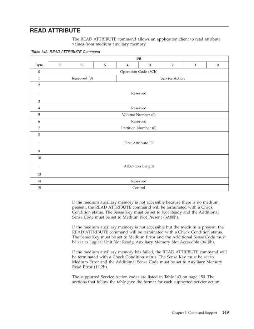
READ ATTRIBUTE
The READ ATTRIBUTE command allows an application client to read attribute
values from medium auxiliary memory.
Table 142. READ ATTRIBUTE Command
Byte
Bit
7 6 5 4 3 2 1 0
0 Operation Code (8Ch)
1 Reserved (0) Service Action
2
:
3
Reserved
4 Reserved
5 Volume Number (0)
6 Reserved
7 Partition Number (0)
8
:
9
First Attribute ID
10
:
13
Allocation Length
14 Reserved
15 Control
If the medium auxiliary memory is not accessible because there is no medium
present, the READ ATTRIBUTE command will be terminated with a Check
Condition status. The Sense Key must be set to Not Ready and the Additional
Sense Code must be set to Medium Not Present (3A00h).
If the medium auxiliary memory is not accessible but the medium is present, the
READ ATTRIBUTE command will be terminated with a Check Condition status.
The Sense Key must be set to Medium Error and the Additional Sense Code must
be set to Logical Unit Not Ready, Auxiliary Memory Not Accessible (0410h).
If the medium auxiliary memory has failed, the READ ATTRIBUTE command will
be terminated with a Check Condition status. The Sense Key must be set to
Medium Error and the Additional Sense Code must be set to Auxiliary Memory
Read Error (1112h).
The supported Service Action codes are listed in Table 143 on page 150. The
sections that follow the table give the format for each supported service action.
Chapter 3. Command Support 149

Table 143. Supported Service Action Codes
Code Name Description Format of Returned Data
00h Attribute Values Return attribute values
See “Format for the Attribute
Values Service Action” on page
152
01h Attribute List
Returns a list of available
attribute identifiers
See “Format for the Attribute
List Service Action” on page
153
02h Volume List
Returns a list of available
Volume Numbers
See “Format for the Volume
List Service Action” on page
154
03h Partition List
Returns a list of available
Partition Numbers
See “Format for the Partition
List Service Action” on page
155
04h Restricted Not applicable Not applicable
05h - 1Fh Reserved Not applicable Not applicable
The First Attribute ID field specifies the attribute identifier of the first attribute to
be returned. If the specified attribute identifier is in the unsupported or
nonexistent state, the READ ATTRIBUTE command will be terminated with a
Check Condition status (see clause 5.10 in the SCSI Primary Commands-3 (SPC-3)).
The Sense Key must be set to Illegal Request and the Additional Sense Code must
be set to Invalid Field in CDB.
The Allocation Length field specifies how many bytes have been allocated for the
returned parameter list. If the length is not sufficient to contain the entire
parameter list, the first portion of the list will be returned. This is not considered
an error. If the remainder of the list is required, the application client should send
a new READ ATTRIBUTE command with an allocation length large enough to
contain the entire parameter list or use the First Attribute ID field to restrict the
attributes that are returned.
The format of parameter data that is returned by the READ ATTRIBUTE command
depends on the service action that is specified.
150 IBM TotalStorage LTO Ultrium Tape Drive: SCSI Reference

Vendor-specific Medium Type Attributes
Table 144 describes the vendor-specific medium type attributes. Application clients
may use Read Attribute to read the contents of the attributes shown in the table.
Table 144. Vendor-specific Medium Type Attributes
Attribute Identifier Name Attribute Length (in bytes) Format
1000h
Unique Cartridge Identity
(UCI)
28 Binary
The Unique Cartridge Identity (UCI) attribute is only supported on Ultrium 3 and
follow-on drives. The Unique Cartridge Identity (UCI) attribute is read only. Any
attempt to change this attribute by using the Write Attribute command will be
rejected by the drive with a Sense Key 5 ASC/ASCQ 2600 Illegal Request, Invalid
Field In Parameter List. If the cartridge has inconsistency between the various
sources from which the components of the UCI are derived, then any command to
read the UCI will be rejected with a Check Condition, and Sense Key and
ASC/ASCQ of (03/1112), which is an Auxiliary Memory Read Error. This error
shall also be reported if the cartridge has not been initialised.
Chapter 3. Command Support 151

Format for the Attribute Values Service Action
The READ ATTRIBUTE command with Attribute Values service action returns
parameter data that contains the attributes that are specified by the Partition
Number, Volume Number, and First Attribute ID fields in the CDB. The returned
parameter data contains the requested attributes in ascending numerical order by
attribute identifier value and in the format shown in Table 145.
Table 145. Parameter Data for an Attribute Values Service Action
Byte
Bit
7 6 5 4 3 2 1 0
0
:
3
Available Data (n-3)
4
:
x
Attribute #1
m
:
n
Attribute #y
The Available Data field will contain the number of bytes of attribute information
in the parameter list. If the parameter list is truncated as a result of insufficient
allocation length, the content of the Available Data field is not altered. The format
of the attribute is described in Table 151 on page 157.
152 IBM TotalStorage LTO Ultrium Tape Drive: SCSI Reference
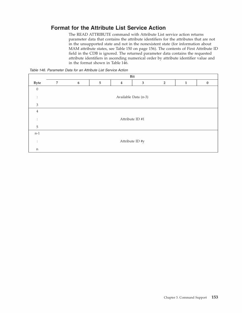
Format for the Attribute List Service Action
The READ ATTRIBUTE command with Attribute List service action returns
parameter data that contains the attribute identifiers for the attributes that are not
in the unsupported state and not in the nonexistent state (for information about
MAM attribute states, see Table 150 on page 156). The contents of First Attribute ID
field in the CDB is ignored. The returned parameter data contains the requested
attribute identifiers in ascending numerical order by attribute identifier value and
in the format shown in Table 146.
Table 146. Parameter Data for an Attribute List Service Action
Byte
Bit
7 6 5 4 3 2 1 0
0
:
3
Available Data (n-3)
4
:
5
Attribute ID #1
n-1
:
n
Attribute ID #y
Chapter 3. Command Support 153

Format for the Volume List Service Action
The READ ATTRIBUTE command with Volume List service action returns
parameter data that identifies the supported number of volumes (see Table 147).
The contents of Volume Number, Partition Number, and First Attribute ID fields in
the CDB are ignored.
Table 147. Parameter Data for a Volume List Service Action
Byte
Bit
7 6 5 4 3 2 1 0
0
:
1
Available Data (2)
2 First Volume Number (0)
3 Number of Volumes Available (1)
The Available Data field contains two.
The First Volume Number field indicates the first volume that is available and will
be set to 0.
The Number of Volumes Available field indicates the number of volumes that are
available and will be set to 1.
154 IBM TotalStorage LTO Ultrium Tape Drive: SCSI Reference

Format for the Partition List Service Action
The READ ATTRIBUTE command with Partition List service action returns
parameter data that identifies the number of partitions that are supported in the
specified volume number (see Table 148). The contents of the Partition Number
and First Attribute ID fields in the CDB are ignored.
Table 148. Parameter Data for a Partition List Service Action
Byte
Bit
7 6 5 4 3 2 1 0
0
:
1
Available Data (2)
2 First Partition Number (0)
3 Number of Partitions Available (1)
The Available Data field contains two.
The First Partition Number field indicates the first partition that is available on the
specified volume number and is set to 0.
The Number of Partitions Available field indicates the number of partitions that are
available on the specified volume number and is set to 1.
Chapter 3. Command Support 155
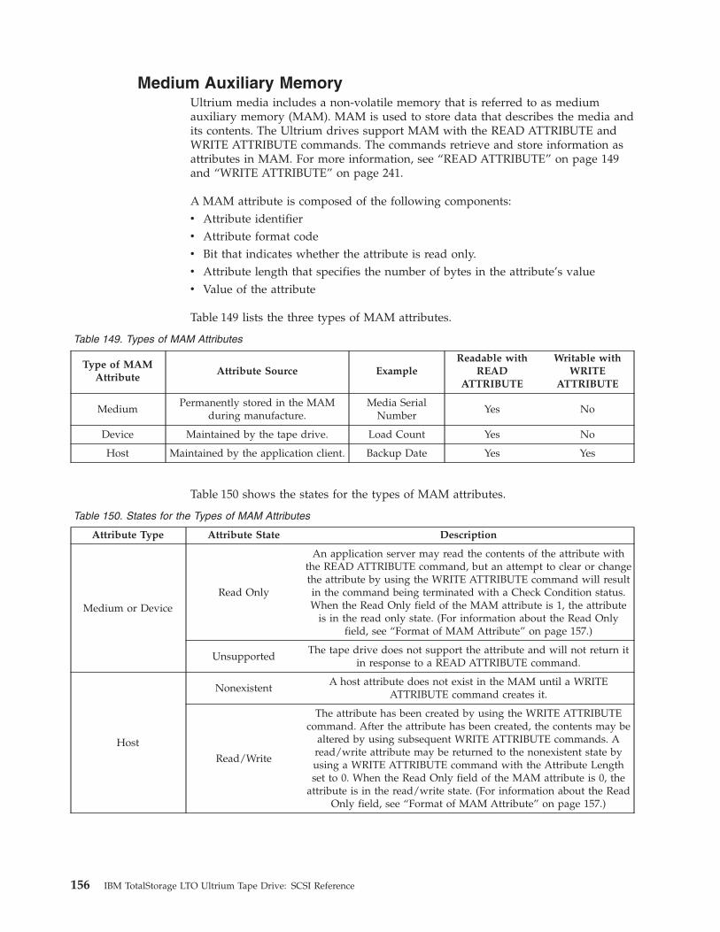
Medium Auxiliary Memory
Ultrium media includes a non-volatile memory that is referred to as medium
auxiliary memory (MAM). MAM is used to store data that describes the media and
its contents. The Ultrium drives support MAM with the READ ATTRIBUTE and
WRITE ATTRIBUTE commands. The commands retrieve and store information as
attributes in MAM. For more information, see “READ ATTRIBUTE” on page 149
and “WRITE ATTRIBUTE” on page 241.
A MAM attribute is composed of the following components:
v Attribute identifier
v Attribute format code
v Bit that indicates whether the attribute is read only.
v Attribute length that specifies the number of bytes in the attribute’s value
v Value of the attribute
Table 149 lists the three types of MAM attributes.
Table 149. Types of MAM Attributes
Type of MAM
Attribute
Attribute Source Example
Readable with
READ
ATTRIBUTE
Writable with
WRITE
ATTRIBUTE
Medium
Permanently stored in the MAM
during manufacture.
Media Serial
Number
Yes No
Device Maintained by the tape drive. Load Count Yes No
Host Maintained by the application client. Backup Date Yes Yes
Table 150 shows the states for the types of MAM attributes.
Table 150. States for the Types of MAM Attributes
Attribute Type Attribute State Description
Medium or Device
Read Only
An application server may read the contents of the attribute with
the READ ATTRIBUTE command, but an attempt to clear or change
the attribute by using the WRITE ATTRIBUTE command will result
in the command being terminated with a Check Condition status.
When the Read Only field of the MAM attribute is 1, the attribute
is in the read only state. (For information about the Read Only
field, see “Format of MAM Attribute” on page 157.)
Unsupported
The tape drive does not support the attribute and will not return it
in response to a READ ATTRIBUTE command.
Host
Nonexistent
A host attribute does not exist in the MAM until a WRITE
ATTRIBUTE command creates it.
Read/Write
The attribute has been created by using the WRITE ATTRIBUTE
command. After the attribute has been created, the contents may be
altered by using subsequent WRITE ATTRIBUTE commands. A
read/write attribute may be returned to the nonexistent state by
using a WRITE ATTRIBUTE command with the Attribute Length
set to 0. When the Read Only field of the MAM attribute is 0, the
attribute is in the read/write state. (For information about the Read
Only field, see “Format of MAM Attribute” on page 157.)
156 IBM TotalStorage LTO Ultrium Tape Drive: SCSI Reference
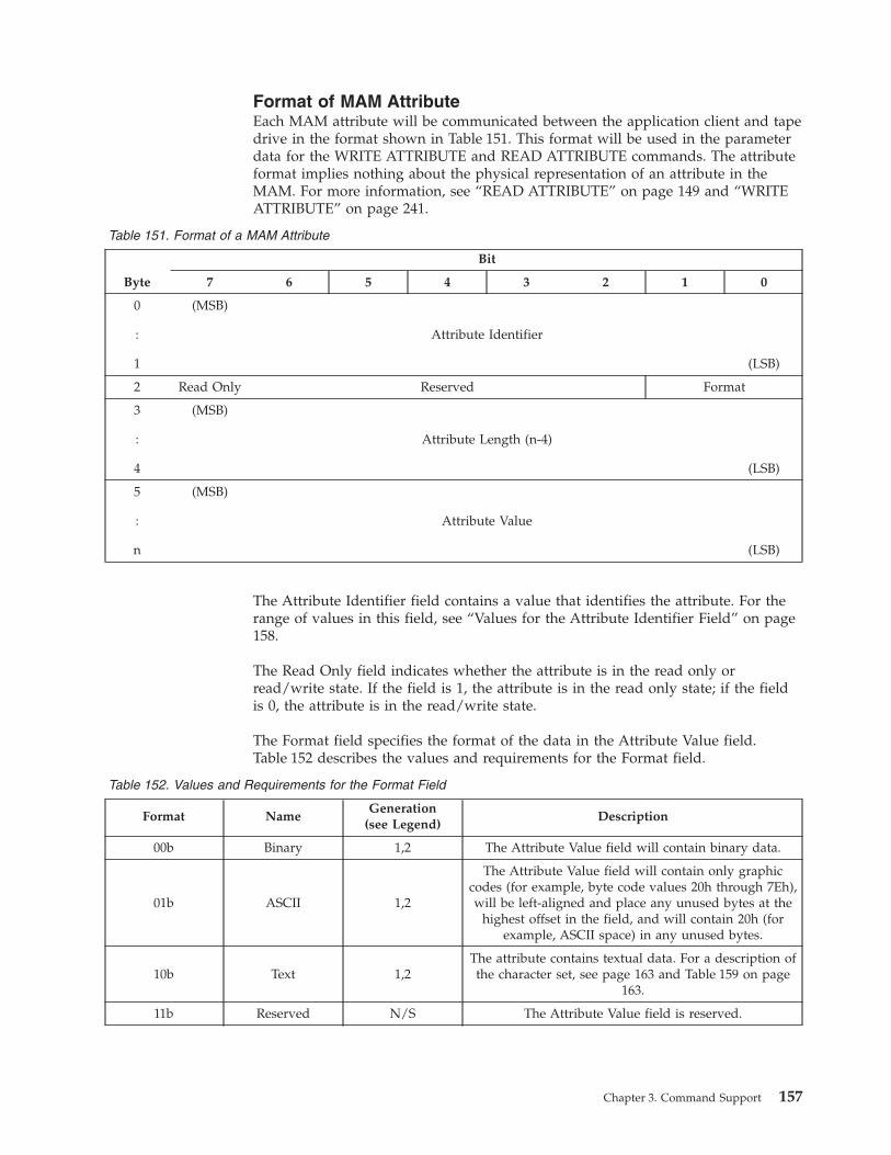
Format of MAM Attribute
Each MAM attribute will be communicated between the application client and tape
drive in the format shown in Table 151. This format will be used in the parameter
data for the WRITE ATTRIBUTE and READ ATTRIBUTE commands. The attribute
format implies nothing about the physical representation of an attribute in the
MAM. For more information, see “READ ATTRIBUTE” on page 149 and “WRITE
ATTRIBUTE” on page 241.
Table 151. Format of a MAM Attribute
Byte
Bit
7 6 5 4 3 2 1 0
0
:
1
(MSB)
Attribute Identifier
(LSB)
2 Read Only Reserved Format
3
:
4
(MSB)
Attribute Length (n-4)
(LSB)
5
:
n
(MSB)
Attribute Value
(LSB)
The Attribute Identifier field contains a value that identifies the attribute. For the
range of values in this field, see “Values for the Attribute Identifier Field” on page
158.
The Read Only field indicates whether the attribute is in the read only or
read/write state. If the field is 1, the attribute is in the read only state; if the field
is 0, the attribute is in the read/write state.
The Format field specifies the format of the data in the Attribute Value field.
Table 152 describes the values and requirements for the Format field.
Table 152. Values and Requirements for the Format Field
Format Name
Generation(see Legend)
Description
00b Binary 1,2 The Attribute Value field will contain binary data.
01b ASCII 1,2
The Attribute Value field will contain only graphic
codes (for example, byte code values 20h through 7Eh),
will be left-aligned and place any unused bytes at the
highest offset in the field, and will contain 20h (for
example, ASCII space) in any unused bytes.
10b Text 1,2
The attribute contains textual data. For a description of
the character set, see page 163 and Table 159 on page
163.
11b Reserved N/S The Attribute Value field is reserved.
Chapter 3. Command Support 157
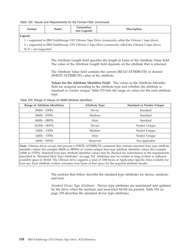
Table 152. Values and Requirements for the Format Field (continued)
Format Name
Generation(see Legend)
Description
Legend:
1 = supported in IBM TotalStorage LTO Ultrium Tape Drive (commonly called the Ultrium 1 tape drive)
2 = supported in IBM TotalStorage LTO Ultrium 2 Tape Drive (commonly called the Ultrium 2 tape drive)
N/S = not supported
The Attribute Length field specifies the length in bytes of the Attribute Value field.
The value of the Attribute Length field depends on the attribute that is returned.
The Attribute Value field contains the current (READ ATTRIBUTE) or desired
(WRITE ATTRIBUTE) value of the attribute.
Values for the Attribute Identifier Field: The values in the Attribute Identifier
field are assigned according to the attribute type and whether the attribute is
standard or vendor unique. Table 153 lists the range of values for the each attribute
type.
Table 153. Range of Values for MAM Attribute Identifiers
Range of Attribute Identifiers Attribute Type Standard or Vendor Unique
0000h - 03FFh Device Standard
0400h - 07FFh Medium Standard
0800h - 0BFFh Host Standard
0C00h - 0FFFh Device Vendor Unique
1000h - 13FFh Medium Vendor Unique
1400h - 17FFh Host Vendor Unique
1800h - FFFFh Reserved Not applicable
Note: Ultrium drives accept and process a WRITE ATTRIBUTE command that contains standard host type attribute
identifier values (for example 0800h to 0BFFh) or vendor-unique host type attribute identifier values (for example
1400h to 17FFh). Standard host type attribute identifier values may be checked for conformance to the requirements
described in “Standard Host Type Attributes” on page 162. Attributes may be written as long as there is sufficient
available space in MAM. The Ultrium drive supports a total of 1008 bytes of Application Specific Data available for
host use. Each attribute written consumes four bytes of that space for the required attribute header.
The sections that follow describe the standard type attributes for device, medium,
and host.
Standard Device Type Attributes: Device type attributes are maintained and updated
by the drive when the medium and associated MAM are present. Table 154 on
page 159 describes the standard device type attributes.
158 IBM TotalStorage LTO Ultrium Tape Drive: SCSI Reference
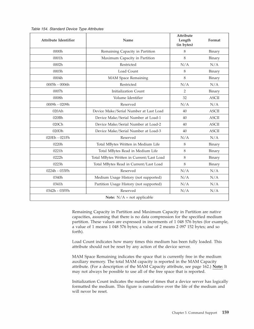
Table 154. Standard Device Type Attributes
Attribute Identifier Name
Attribute
Length(in bytes)
Format
0000h Remaining Capacity in Partition 8 Binary
0001h Maximum Capacity in Partition 8 Binary
0002h Restricted N/A N/A
0003h Load Count 8 Binary
0004h MAM Space Remaining 8 Binary
0005h - 0006h Restricted N/A N/A
0007h Initialization Count 2 Binary
0008h Volume Identifier 32 ASCII
0009h - 0209h Reserved N/A N/A
020Ah Device Make/Serial Number at Last Load 40 ASCII
020Bh Device Make/Serial Number at Load-1 40 ASCII
020Ch Device Make/Serial Number at Load-2 40 ASCII
020Dh Device Make/Serial Number at Load-3 40 ASCII
020Eh - 021Fh Reserved N/A N/A
0220h Total MBytes Written in Medium Life 8 Binary
0221h Total MBytes Read in Medium Life 8 Binary
0222h Total MBytes Written in Current/Last Load 8 Binary
0223h Total MBytes Read in Current/Last Load 8 Binary
0224h - 033Fh Reserved N/A N/A
0340h Medium Usage History (not supported) N/A N/A
0341h Partition Usage History (not supported) N/A N/A
0342h - 03FFh Reserved N/A N/A
Note: N/A = not applicable
Remaining Capacity in Partition and Maximum Capacity in Partition are native
capacities, assuming that there is no data compression for the specified medium
partition. These values are expressed in increments of 1 048 576 bytes (for example,
a value of 1 means 1 048 576 bytes; a value of 2 means 2 097 152 bytes; and so
forth).
Load Count indicates how many times this medium has been fully loaded. This
attribute should not be reset by any action of the device server.
MAM Space Remaining indicates the space that is currently free in the medium
auxiliary memory. The total MAM capacity is reported in the MAM Capacity
attribute. (For a description of the MAM Capacity attribute, see page 162.) Note: It
may not always be possible to use all of the free space that is reported.
Initialization Count indicates the number of times that a device server has logically
formatted the medium. This figure is cumulative over the life of the medium and
will never be reset.
Chapter 3. Command Support 159
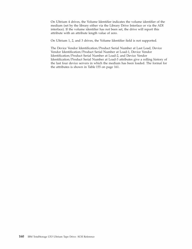
On Ultrium 4 drives, the Volume Identifier indicates the volume identifier of the
medium (set by the library either via the Library Drive Interface or via the ADI
interface). If the volume identifier has not been set, the drive will report this
attribute with an attribute length value of zero.
On Ultrium 1, 2, and 3 drives, the Volume Identifier field is not supported.
The Device Vendor Identification/Product Serial Number at Last Load, Device
Vendor Identification/Product Serial Number at Load-1, Device Vendor
Identification/Product Serial Number at Load-2, and Device Vendor
Identification/Product Serial Number at Load-3 attributes give a rolling history of
the last four device servers in which the medium has been loaded. The format for
the attributes is shown in Table 155 on page 161.
160 IBM TotalStorage LTO Ultrium Tape Drive: SCSI Reference
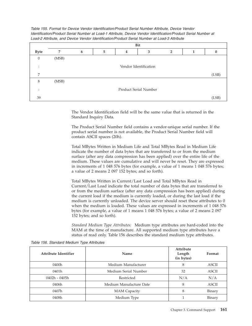
Table 155. Format for Device Vendor Identification/Product Serial Number Attribute, Device Vendor
Identification/Product Serial Number at Load-1 Attribute, Device Vendor Identification/Product Serial Number at
Load-2 Attribute, and Device Vendor Identification/Product Serial Number at Load-3 Attribute
Byte
Bit
7 6 5 4 3 2 1 0
0
:
7
(MSB)
Vendor Identification
(LSB)
8
:
39
(MSB)
Product Serial Number
(LSB)
The Vendor Identification field will be the same value that is returned in the
Standard Inquiry Data.
The Product Serial Number field contains a vendor-unique serial number. If the
product serial number is not available, the Product Serial Number field will
contain ASCII spaces (20h).
Total MBytes Written in Medium Life and Total MBytes Read in Medium Life
indicate the number of data bytes that are transferred to or from the medium
surface (after any data compression has been applied) over the entire life of the
medium. These values are cumulative and will never be reset. They are expressed
in increments of 1 048 576 bytes (for example, a value of 1 means 1 048 576 bytes;
a value of 2 means 2 097 152 bytes; and so forth).
Total MBytes Written in Current/Last Load and Total MBytes Read in
Current/Last Load indicate the total number of data bytes that are transferred to
or from the medium surface (after any data compression has been applied) during
the current load if the medium is currently loaded, or during the last load if the
medium is currently unloaded. The device server should reset these attributes to 0
when the medium is loaded. These values are expressed in increments of 1 048 576
bytes (for example, a value of 1 means 1 048 576 bytes; a value of 2 means 2 097
152 bytes; and so forth).
Standard Medium Type Attributes: Medium type attributes are hard-coded into the
MAM at the time of manufacture. All supported medium type attributes have a
status of read only. Table 156 describes the standard medium type attributes.
Table 156. Standard Medium Type Attributes
Attribute Identifier Name
Attribute
Length(in bytes)
Format
0400h Medium Manufacturer 8 ASCII
0401h Medium Serial Number 32 ASCII
0402h - 0405h Restricted N/A N/A
0406h Medium Manufacture Date 8 ASCII
0407h MAM Capacity 8 Binary
0408h Medium Type 1 Binary
Chapter 3. Command Support 161
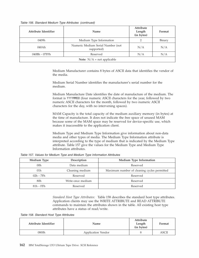
Table 156. Standard Medium Type Attributes (continued)
Attribute Identifier Name
Attribute
Length(in bytes)
Format
0409h Medium Type Information 2 Binary
040Ah
Numeric Medium Serial Number (not
supported)
N/A N/A
040Bh - 07FFh Reserved N/A N/A
Note: N/A = not applicable
Medium Manufacturer contains 8 bytes of ASCII data that identifies the vendor of
the media.
Medium Serial Number identifies the manufacturer’s serial number for the
medium.
Medium Manufacture Date identifies the date of manufacture of the medium. The
format is YYYYMMDD (four numeric ASCII characters for the year, followed by two
numeric ASCII characters for the month, followed by two numeric ASCII
characters for the day, with no intervening spaces).
MAM Capacity is the total capacity of the medium auxiliary memory (in bytes) at
the time of manufacture. It does not indicate the free space of unused MAM
because some of the MAM space may be reserved for device-specific use, which
makes it inaccessible to the application client.
Medium Type and Medium Type Information give information about non-data
media and other types of media. The Medium Type Information attribute is
interpreted according to the type of medium that is indicated by the Medium Type
attribute. Table 157 give the values for the Medium Type and Medium Type
Information attributes.
Table 157. Values for Medium Type and Medium Type Information Attributes
Medium Type Description Medium Type Information
00h Data medium Reserved
01h Cleaning medium Maximum number of cleaning cycles permitted
02h - 7Fh Reserved Reserved
80h Write-once medium Reserved
81h - FFh Reserved Reserved
Standard Host Type Attributes: Table 158 describes the standard host type attributes.
Application clients may use the WRITE ATTRIBUTE and READ ATTRIBUTE
commands to maintain the attributes shown in the table. All existing host type
attributes have a status of read/write.
Table 158. Standard Host Type Attributes
Attribute Identifier Name
Attribute
Length(in bytes)
Format
0800h Application Vendor 8 ASCII
162 IBM TotalStorage LTO Ultrium Tape Drive: SCSI Reference
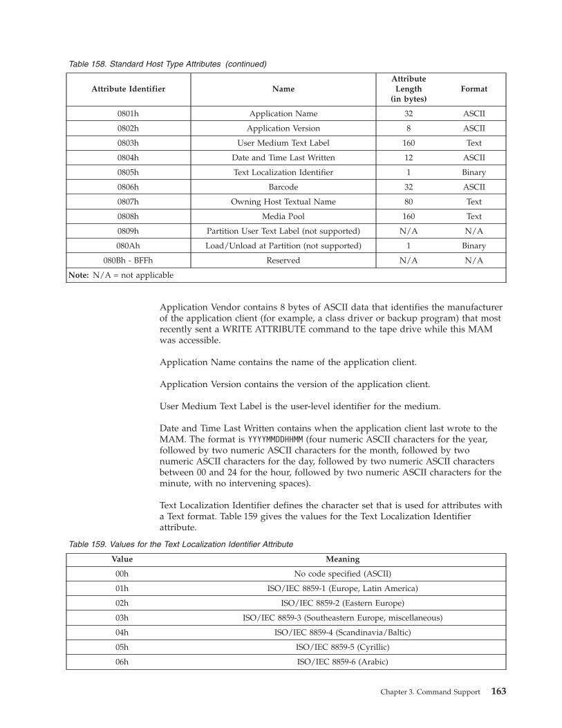
Table 158. Standard Host Type Attributes (continued)
Attribute Identifier Name
Attribute
Length(in bytes)
Format
0801h Application Name 32 ASCII
0802h Application Version 8 ASCII
0803h User Medium Text Label 160 Text
0804h Date and Time Last Written 12 ASCII
0805h Text Localization Identifier 1 Binary
0806h Barcode 32 ASCII
0807h Owning Host Textual Name 80 Text
0808h Media Pool 160 Text
0809h Partition User Text Label (not supported) N/A N/A
080Ah Load/Unload at Partition (not supported) 1 Binary
080Bh - BFFh Reserved N/A N/A
Note: N/A = not applicable
Application Vendor contains 8 bytes of ASCII data that identifies the manufacturer
of the application client (for example, a class driver or backup program) that most
recently sent a WRITE ATTRIBUTE command to the tape drive while this MAM
was accessible.
Application Name contains the name of the application client.
Application Version contains the version of the application client.
User Medium Text Label is the user-level identifier for the medium.
Date and Time Last Written contains when the application client last wrote to the
MAM. The format is YYYYMMDDHHMM (four numeric ASCII characters for the year,
followed by two numeric ASCII characters for the month, followed by two
numeric ASCII characters for the day, followed by two numeric ASCII characters
between 00 and 24 for the hour, followed by two numeric ASCII characters for the
minute, with no intervening spaces).
Text Localization Identifier defines the character set that is used for attributes with
a Text format. Table 159 gives the values for the Text Localization Identifier
attribute.
Table 159. Values for the Text Localization Identifier Attribute
Value Meaning
00h No code specified (ASCII)
01h ISO/IEC 8859-1 (Europe, Latin America)
02h ISO/IEC 8859-2 (Eastern Europe)
03h ISO/IEC 8859-3 (Southeastern Europe, miscellaneous)
04h ISO/IEC 8859-4 (Scandinavia/Baltic)
05h ISO/IEC 8859-5 (Cyrillic)
06h ISO/IEC 8859-6 (Arabic)
Chapter 3. Command Support 163
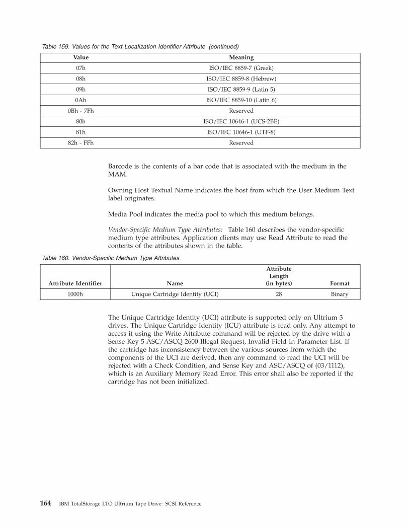
Table 159. Values for the Text Localization Identifier Attribute (continued)
Value Meaning
07h ISO/IEC 8859-7 (Greek)
08h ISO/IEC 8859-8 (Hebrew)
09h ISO/IEC 8859-9 (Latin 5)
0Ah ISO/IEC 8859-10 (Latin 6)
0Bh - 7Fh Reserved
80h ISO/IEC 10646-1 (UCS-2BE)
81h ISO/IEC 10646-1 (UTF-8)
82h - FFh Reserved
Barcode is the contents of a bar code that is associated with the medium in the
MAM.
Owning Host Textual Name indicates the host from which the User Medium Text
label originates.
Media Pool indicates the media pool to which this medium belongs.
Vendor-Specific Medium Type Attributes: Table 160 describes the vendor-specific
medium type attributes. Application clients may use Read Attribute to read the
contents of the attributes shown in the table.
Table 160. Vendor-Specific Medium Type Attributes
Attribute Identifier Name
AttributeLength
(in bytes) Format
1000h Unique Cartridge Identity (UCI) 28 Binary
The Unique Cartridge Identity (UCI) attribute is supported only on Ultrium 3
drives. The Unique Cartridge Identity (ICU) attribute is read only. Any attempt to
access it using the Write Attribute command will be rejected by the drive with a
Sense Key 5 ASC/ASCQ 2600 Illegal Request, Invalid Field In Parameter List. If
the cartridge has inconsistency between the various sources from which the
components of the UCI are derived, then any command to read the UCI will be
rejected with a Check Condition, and Sense Key and ASC/ASCQ of (03/1112),
which is an Auxiliary Memory Read Error. This error shall also be reported if the
cartridge has not been initialized.
164 IBM TotalStorage LTO Ultrium Tape Drive: SCSI Reference
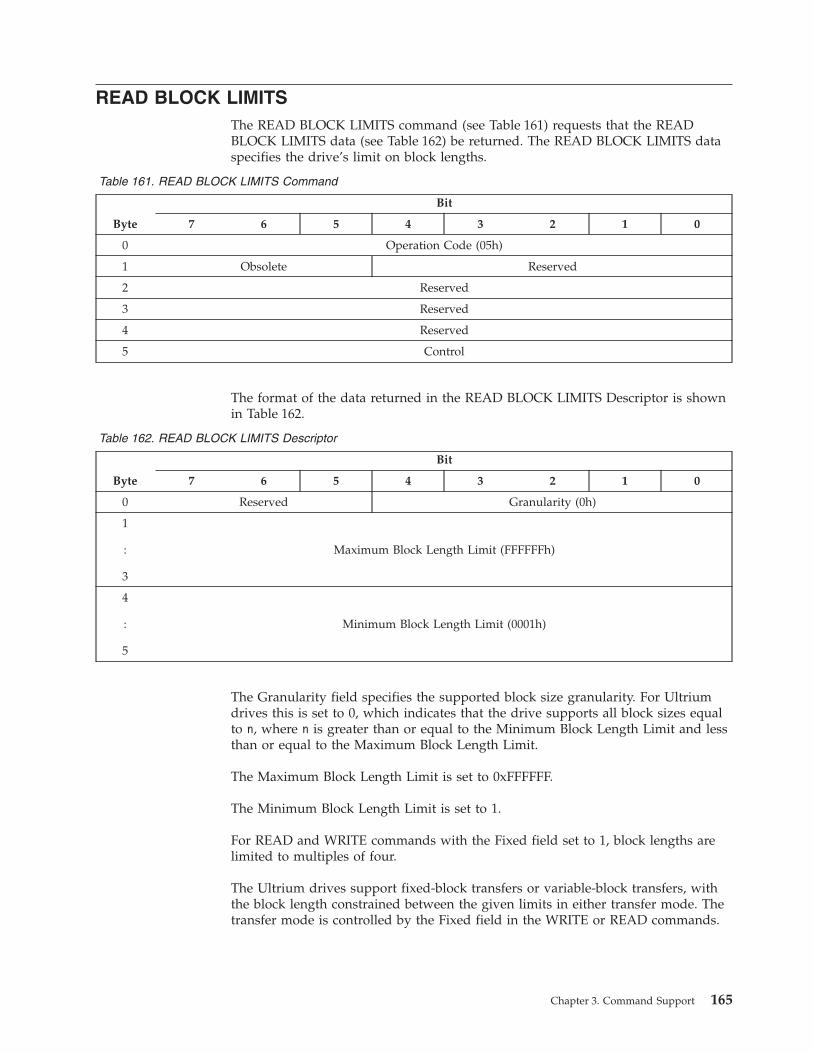
READ BLOCK LIMITS
The READ BLOCK LIMITS command (see Table 161) requests that the READ
BLOCK LIMITS data (see Table 162) be returned. The READ BLOCK LIMITS data
specifies the drive’s limit on block lengths.
Table 161. READ BLOCK LIMITS Command
Byte
Bit
7 6 5 4 3 2 1 0
0 Operation Code (05h)
1 Obsolete Reserved
2 Reserved
3 Reserved
4 Reserved
5 Control
The format of the data returned in the READ BLOCK LIMITS Descriptor is shown
in Table 162.
Table 162. READ BLOCK LIMITS Descriptor
Byte
Bit
7 6 5 4 3 2 1 0
0 Reserved Granularity (0h)
1
:
3
Maximum Block Length Limit (FFFFFFh)
4
:
5
Minimum Block Length Limit (0001h)
The Granularity field specifies the supported block size granularity. For Ultrium
drives this is set to 0, which indicates that the drive supports all block sizes equal
to n, where n is greater than or equal to the Minimum Block Length Limit and less
than or equal to the Maximum Block Length Limit.
The Maximum Block Length Limit is set to 0xFFFFFF.
The Minimum Block Length Limit is set to 1.
For READ and WRITE commands with the Fixed field set to 1, block lengths are
limited to multiples of four.
The Ultrium drives support fixed-block transfers or variable-block transfers, with
the block length constrained between the given limits in either transfer mode. The
transfer mode is controlled by the Fixed field in the WRITE or READ commands.
Chapter 3. Command Support 165
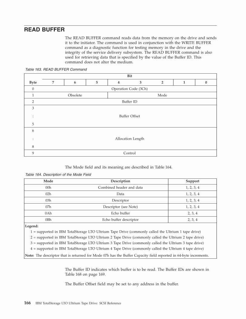
READ BUFFER
The READ BUFFER command reads data from the memory on the drive and sends
it to the initiator. The command is used in conjunction with the WRITE BUFFER
command as a diagnostic function for testing memory in the drive and the
integrity of the service delivery subsystem. The READ BUFFER command is also
used for retrieving data that is specified by the value of the Buffer ID. This
command does not alter the medium.
Table 163. READ BUFFER Command
Byte
Bit
7 6 5 4 3 2 1 0
0 Operation Code (3Ch)
1 Obsolete Mode
2 Buffer ID
3
:
5
Buffer Offset
6
:
8
Allocation Length
9 Control
The Mode field and its meaning are described in Table 164.
Table 164. Description of the Mode Field
Mode Description Support
00h Combined header and data 1, 2, 3, 4
02h Data 1, 2, 3, 4
03h Descriptor 1, 2, 3, 4
07h Descriptor (see Note) 1, 2, 3, 4
0Ah Echo buffer 2, 3, 4
0Bh Echo buffer descriptor 2, 3, 4
Legend:
1 = supported in IBM TotalStorage LTO Ultrium Tape Drive (commonly called the Ultrium 1 tape drive)
2 = supported in IBM TotalStorage LTO Ultrium 2 Tape Drive (commonly called the Ultrium 2 tape drive)
3 = supported in IBM TotalStorage LTO Ultrium 3 Tape Drive (commonly called the Ultrium 3 tape drive)
4 = supported in IBM TotalStorage LTO Ultrium 4 Tape Drive (commonly called the Ultrium 4 tape drive)
Note: The descriptor that is returned for Mode 07h has the Buffer Capacity field reported in 64-byte increments.
The Buffer ID indicates which buffer is to be read. The Buffer IDs are shown in
Table 168 on page 169.
The Buffer Offset field may be set to any address in the buffer.
166 IBM TotalStorage LTO Ultrium Tape Drive: SCSI Reference
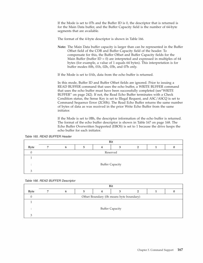
If the Mode is set to 07h and the Buffer ID is 0, the descriptor that is returned is
for the Main Data buffer, and the Buffer Capacity field is the number of 64-byte
segments that are available.
The format of the 4-byte descriptor is shown in Table 166.
Note: The Main Data buffer capacity is larger than can be represented in the Buffer
Offset field of the CDB and Buffer Capacity field of the header. To
compensate for this, the Buffer Offset and Buffer Capacity fields for the
Main Buffer (buffer ID = 0) are interpreted and expressed in multiples of 64
bytes (for example, a value of 1 equals 64 bytes). This interpretation is for
buffer modes 00h, 01h, 02h, 03h, and 07h only.
If the Mode is set to 0Ah, data from the echo buffer is returned.
In this mode, Buffer ID and Buffer Offset fields are ignored. Prior to issuing a
READ BUFFER command that uses the echo buffer, a WRITE BUFFER command
that uses the echo buffer must have been successfully completed (see“WRITE
BUFFER” on page 242). If not, the Read Echo Buffer terminates with a Check
Condition status, the Sense Key is set to Illegal Request, and ASC/ASCQ is set to
Command Sequence Error (2C00h). The Read Echo Buffer returns the same number
of bytes of data as was received in the prior Write Echo Buffer from the same
initiator.
If the Mode is set to 0Bh, the descriptor information of the echo buffer is returned.
The format of the echo buffer descriptor is shown in Table 167 on page 168. The
Echo Buffer Overwritten Supported (EBOS) is set to 1 because the drive keeps the
echo buffer for each initiator.
Table 165. READ BUFFER Header
Byte
Bit
7 6 5 4 3 2 1 0
0 Reserved
1
:
3
Buffer Capacity
Table 166. READ BUFFER Descriptor
Byte
Bit
7 6 5 4 3 2 1 0
0 Offset Boundary (0h means byte boundary)
1
:
3
Buffer Capacity
Chapter 3. Command Support 167

Table 167. READ ECHO BUFFER Descriptor
Byte
Bit
7 6 5 4 3 2 1 0
0 Reserved EBOS(1)
1 Reserved
2 Reserved Buffer Capacity
3 Buffer Capacity
168 IBM TotalStorage LTO Ultrium Tape Drive: SCSI Reference

Table 168. Drive Buffers
Supported Buffers ID Offset Boundary Ultrium Support
Main Data 00h 4 1, 2, 3, 4
Dump Data (Read Only) (See Note) 01h 4 1, 2, 3, 4
Test 02h 4 1, 2, 3, 4
VPD 03h 4 1, 2, 3, 4
Firmware 04h 4 1, 2, 3, 4
Cartridge Memory (Read Only) 05h 4 1, 2, 3, 4
Error Log (Read Only) 06h 4 1, 2, 3, 4
SCSI Log (Read Only) 07h 4 1, 2, 3, 4
08h 4 1, 2, 3, 4
Reserved 09h-80h N/A N/A
(IBM use only) 81h N/A N/A
(IBM use only) 83h N/A N/A
Reserved 84h-FFh N/A N/A
Legend:
1 = supported in IBM TotalStorage LTO Ultrium Tape Drive (commonly called the Ultrium 1 tape drive)
2 = supported in IBM TotalStorage LTO Ultrium 2 Tape Drive (commonly called the Ultrium 2 tape drive)
3 = supported in IBM TotalStorage LTO Ultrium 3 Tape Drive (commonly called the Ultrium 3 tape drive)
N/A = not applicable
4 = supported in IBM TotalStorage LTO Ultrium 4 Tape Drive (commonly called the Ultrium 4 tape drive)
Note: When reading dump data on a Fibre Channel drive, take care to ensure that the amount of data in each
transfer does not exceed the DMA settings of the HBA. The dump data currently exceeds 1 MB in size. The
default DMA setting for some HBAs is 1 MB. For this reason, it is recommended that the dump data is read in a
series of smaller blocks with appropriate offsets (for example, 64 K bytes).
Note: When reading dump data the data should be read with strictly increasing offsets. If it is not read with
strictly increasing offsets and a new dump is created during the readi processing, the data might be corrupted
Chapter 3. Command Support 169
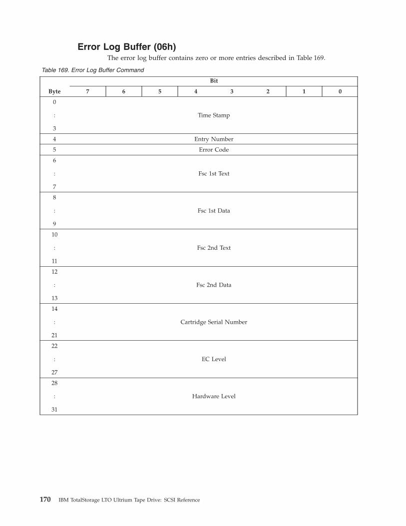
Error Log Buffer (06h)
The error log buffer contains zero or more entries described in Table 169.
Table 169. Error Log Buffer Command
Byte
Bit
7 6 5 4 3 2 1 0
0
:
3
Time Stamp
4 Entry Number
5 Error Code
6
:
7
Fsc 1st Text
8
:
9
Fsc 1st Data
10
:
11
Fsc 2nd Text
12
:
13
Fsc 2nd Data
14
:
21
Cartridge Serial Number
22
:
27
EC Level
28
:
31
Hardware Level
170 IBM TotalStorage LTO Ultrium Tape Drive: SCSI Reference
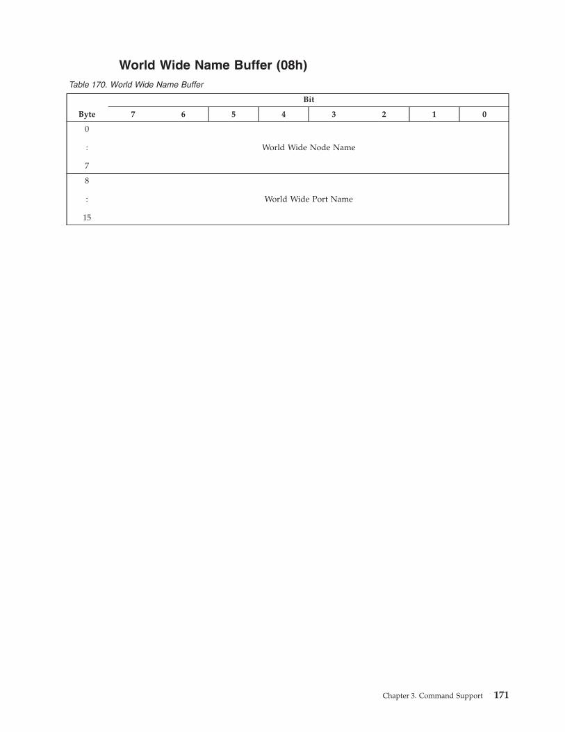
World Wide Name Buffer (08h)
Table 170. World Wide Name Buffer
Byte
Bit
7 6 5 4 3 2 1 0
0
:
7
World Wide Node Name
8
:
15
World Wide Port Name
Chapter 3. Command Support 171
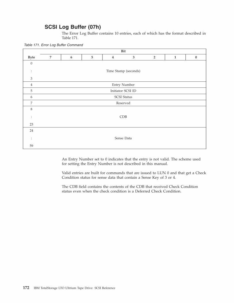
SCSI Log Buffer (07h)
The Error Log Buffer contains 10 entries, each of which has the format described in
Table 171.
Table 171. Error Log Buffer Command
Byte
Bit
7 6 5 4 3 2 1 0
0
:
3
Time Stamp (seconds)
4 Entry Number
5 Initiator SCSI ID
6 SCSI Status
7 Reserved
8
:
23
CDB
24
:
59
Sense Data
An Entry Number set to 0 indicates that the entry is not valid. The scheme used
for setting the Entry Number is not described in this manual.
Valid entries are built for commands that are issued to LUN 0 and that get a Check
Condition status for sense data that contain a Sense Key of 3 or 4.
The CDB field contains the contents of the CDB that received Check Condition
status even when the check condition is a Deferred Check Condition.
172 IBM TotalStorage LTO Ultrium Tape Drive: SCSI Reference
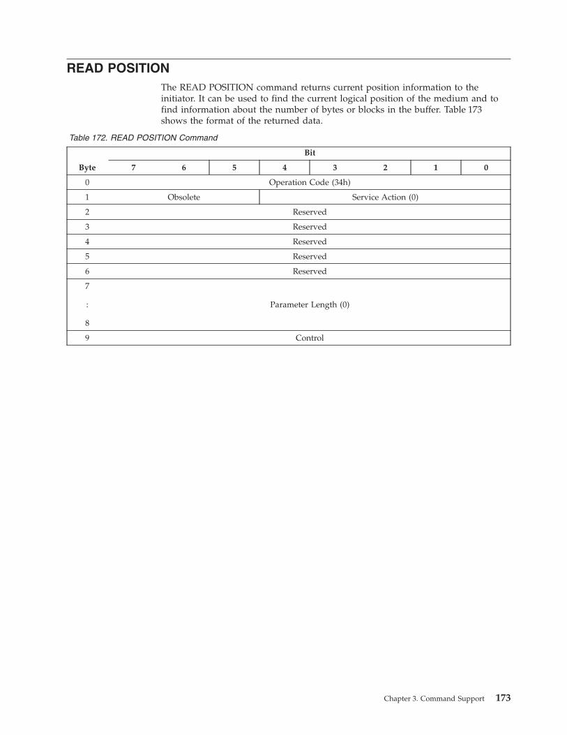
READ POSITION
The READ POSITION command returns current position information to the
initiator. It can be used to find the current logical position of the medium and to
find information about the number of bytes or blocks in the buffer. Table 173
shows the format of the returned data.
Table 172. READ POSITION Command
Byte
Bit
7 6 5 4 3 2 1 0
0 Operation Code (34h)
1 Obsolete Service Action (0)
2 Reserved
3 Reserved
4 Reserved
5 Reserved
6 Reserved
7
:
8
Parameter Length (0)
9 Control
Chapter 3. Command Support 173

Table 173. READ POSITION Data
Byte
Bit
7 6 5 4 3 2 1 0
0 BOP EOP BCU BYCU(1) Rsvd BPU(0) PERR(0) Rsvd
1 Partition Number (0)
2 Reserved
3 Reserved
4
:
7
First Block Location
8
:
11
Last Block Location
12 Reserved
13
:
15
Number of blocks in buffer
16
:
19
Number of bytes in buffer (0)
The First Block Location specifies the block address that is associated with the
current logical position. The value indicates the block address of the next data
block to be transferred between the initiator and the target if a READ or WRITE
command is issued.
The Last Block Location is specified by the following procedure:
1. After a WRITE, WRITE FILEMARK, or any command failed for a deferred
write error, this field specifies the block address that is associated with the next
block to be transferred from the buffer to the medium.
2. After a successful read type command (for example Read, Space, Locate,
non-immediate Rewind), this field is returned as 0.
The Beginning of Partition (BOP) field is set if the Block Location fields are 0.
An end-of-partition (EOP) field of 1 specifies that the logical unit is positioned
between early-warning and end-of-partition. An EOP field of 0 specifies that the
current logical position is not between early-warning.
The Block Position Unknown (BPU) field is always set to 0, because the position is
always known.
The Partition Number is set to 0 because partitioning is not supported.
174 IBM TotalStorage LTO Ultrium Tape Drive: SCSI Reference
A block count unknown (BCU) field of 1 indicates that the Number of Blocks in
Buffer field does not represent the actual number of blocks in the buffer. A BCU
field of 0 indicates that the Number of Blocks in Buffer field is valid.
A byte count unknown (BYCU) field of 1 indicates that the Number of Bytes in
Buffer field does not represent the actual number of bytes in the buffer. This field
is always set to 1.
The Number of blocks in buffer field is specified by the following procedure:
1. After WRITE, WRITE FILEMARK, or any command failed for a deferred write
error, this field specifies the number of unwritten data blocks and filemarks
that are still in the buffer.
2. After successful read type commands this field will always return 0.
Chapter 3. Command Support 175
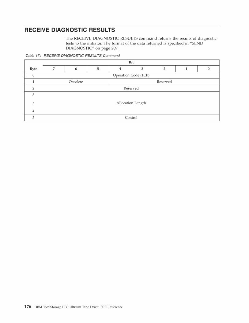
RECEIVE DIAGNOSTIC RESULTS
The RECEIVE DIAGNOSTIC RESULTS command returns the results of diagnostic
tests to the initiator. The format of the data returned is specified in “SEND
DIAGNOSTIC” on page 209.
Table 174. RECEIVE DIAGNOSTIC RESULTS Command
Byte
Bit
7 6 5 4 3 2 1 0
0 Operation Code (1Ch)
1 Obsolete Reserved
2 Reserved
3
:
4
Allocation Length
5 Control
176 IBM TotalStorage LTO Ultrium Tape Drive: SCSI Reference
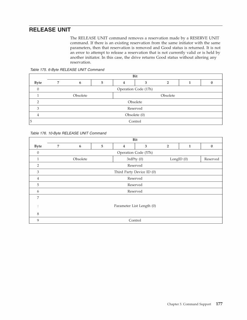
RELEASE UNIT
The RELEASE UNIT command removes a reservation made by a RESERVE UNIT
command. If there is an existing reservation from the same initiator with the same
parameters, then that reservation is removed and Good status is returned. It is not
an error to attempt to release a reservation that is not currently valid or is held by
another initiator. In this case, the drive returns Good status without altering any
reservation.
Table 175. 6-Byte RELEASE UNIT Command
Byte
Bit
7 6 5 4 3 2 1 0
0 Operation Code (17h)
1 Obsolete Obsolete
2 Obsolete
3 Reserved
4 Obsolete (0)
5 Control
Table 176. 10-Byte RELEASE UNIT Command
Byte
Bit
7 6 5 4 3 2 1 0
0 Operation Code (57h)
1 Obsolete 3rdPty (0) LongID (0) Reserved
2 Reserved
3 Third Party Device ID (0)
4 Reserved
5 Reserved
6 Reserved
7
:
8
Parameter List Length (0)
9 Control
Chapter 3. Command Support 177
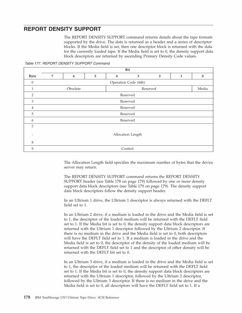
REPORT DENSITY SUPPORT
The REPORT DENSITY SUPPORT command returns details about the tape formats
supported by the drive. The data is returned as a header and a series of descriptor
blocks. If the Media field is set, then one descriptor block is returned with the data
for the currently loaded tape. If the Media field is set to 0, the density support data
block descriptors are returned by ascending Primary Density Code values.
Table 177. REPORT DENSITY SUPPORT Command
Byte
Bit
7 6 5 4 3 2 1 0
0 Operation Code (44h)
1 Obsolete Reserved Media
2 Reserved
3 Reserved
4 Reserved
5 Reserved
6 Reserved
7
:
8
Allocation Length
9 Control
The Allocation Length field specifies the maximum number of bytes that the device
server may return.
The REPORT DENSITY SUPPORT command returns the REPORT DENSITY
SUPPORT header (see Table 178 on page 179) followed by one or more density
support data block descriptors (see Table 179 on page 179). The density support
data block descriptors follow the density support header.
In an Ultrium 1 drive, the Ultrium 1 descriptor is always returned with the DEFLT
field set to 1.
In an Ultrium 2 drive, if a medium is loaded in the drive and the Media field is set
to 1, the descriptor of the loaded medium will be returned with the DEFLT field
set to 1. If the Media bit is set to 0, the density support data block descriptors are
returned with the Ultrium 1 descriptor followed by the Ultrium 2 descriptor. If
there is no medium in the drive and the Media field is set to 0, both descriptors
will have the DEFLT field set to 1. If a medium is loaded in the drive and the
Media field is set to 0, the descriptor of the density of the loaded medium will be
returned with the DEFLT field set to 1 and the descriptor of other density will be
returned with the DEFLT bit set to 0.
In an Ultrium 3 drive, if a medium is loaded in the drive and the Media field is set
to 1, the descriptor of the loaded medium will be returned with the DEFLT field
set to 1. If the Media bit is set to 0, the density support data block descriptors are
returned with the Ultrium 1 descriptor, followed by the Ultrium 2 descriptor,
followed by the Ultrium 3 descriptor. If there is no medium in the drive and the
Media field is set to 0, all descriptors will have the DEFLT field set to 1. If a
178 IBM TotalStorage LTO Ultrium Tape Drive: SCSI Reference
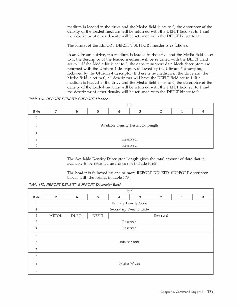
medium is loaded in the drive and the Media field is set to 0, the descriptor of the
density of the loaded medium will be returned with the DEFLT field set to 1 and
the descriptor of other density will be returned with the DEFLT bit set to 0.
The format of the REPORT DENSITY SUPPORT header is as follows:
In an Ultrium 4 drive, if a medium is loaded in the drive and the Media field is set
to 1, the descriptor of the loaded medium will be returned with the DEFLT field
set to 1. If the Media bit is set to 0, the density support data block descriptors are
returned with the Ultrium 2 descriptor, followed by the Ultrium 3 descriptor,
followed by the Ultrium 4 descriptor. If there is no medium in the drive and the
Media field is set to 0, all descriptors will have the DEFLT field set to 1. If a
medium is loaded in the drive and the Media field is set to 0, the descriptor of the
density of the loaded medium will be returned with the DEFLT field set to 1 and
the descriptor of other density will be returned with the DEFLT bit set to 0.
Table 178. REPORT DENSITY SUPPORT Header
Byte
Bit
7 6 5 4 3 2 1 0
0
:
1
Available Density Descriptor Length
2 Reserved
3 Reserved
The Available Density Descriptor Length gives the total amount of data that is
available to be returned and does not include itself.
The header is followed by one or more REPORT DENSITY SUPPORT descriptor
blocks with the format in Table 179.
Table 179. REPORT DENSITY SUPPORT Descriptor Block
Byte
Bit
7 6 5 4 3 2 1 0
0 Primary Density Code
1 Secondary Density Code
2 WRTOK DUP(0) DEFLT Reserved
3 Reserved
4 Reserved
5
:
7
Bits per mm
8
:
9
Media Width
Chapter 3. Command Support 179
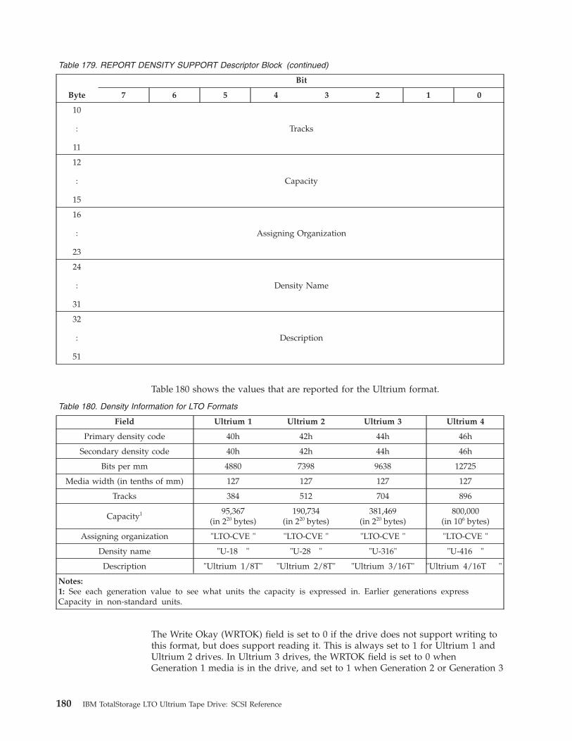
Table 179. REPORT DENSITY SUPPORT Descriptor Block (continued)
Byte
Bit
7 6 5 4 3 2 1 0
10
:
11
Tracks
12
:
15
Capacity
16
:
23
Assigning Organization
24
:
31
Density Name
32
:
51
Description
Table 180 shows the values that are reported for the Ultrium format.
Table 180. Density Information for LTO Formats
Field Ultrium 1 Ultrium 2 Ultrium 3 Ultrium 4
Primary density code 40h 42h 44h 46h
Secondary density code 40h 42h 44h 46h
Bits per mm 4880 7398 9638 12725
Media width (in tenths of mm) 127 127 127 127
Tracks 384 512 704 896
Capacity1
95,367(in 220 bytes)
190,734(in 220 bytes)
381,469(in 220 bytes)
800,000(in 106 bytes)
Assigning organization "LTO-CVE " "LTO-CVE " "LTO-CVE " "LTO-CVE "
Density name "U-18 " "U-28 " "U-316" "U-416 "
Description "Ultrium 1/8T" "Ultrium 2/8T" "Ultrium 3/16T" "Ultrium 4/16T "
Notes:
1: See each generation value to see what units the capacity is expressed in. Earlier generations express
Capacity in non-standard units.
The Write Okay (WRTOK) field is set to 0 if the drive does not support writing to
this format, but does support reading it. This is always set to 1 for Ultrium 1 and
Ultrium 2 drives. In Ultrium 3 drives, the WRTOK field is set to 0 when
Generation 1 media is in the drive, and set to 1 when Generation 2 or Generation 3
180 IBM TotalStorage LTO Ultrium Tape Drive: SCSI Reference
media is in the drive. In Ultrium 4 drives, the WRTOK field is set to 0 when
Generation 1 or Generation 2 media is in the drive, and set to 1 when Generation 3
or Generation 4 media is in the drive.
The Duplicate (DUP) field is set to 0 for every descriptor block, indicating that
each density is reported only once. A DEFLT field of 0 specifies that this density is
not the default density of the drive. A DEFLT field of 1 specifies that this density is
the default density.
Note: The default density of the drive will vary, depending on the currently
mounted media. Multiple codes may return a DEFLT field of 1 when the
Media field is 0 because more than one default is possible.
If the Media field is set to 0, the maximum values possible are reported. In Ultrium
2 drives, the Ultrium 1 descriptor is returned, followed by the Ultrium 2
descriptor. In Ultrium 3 drives, the Ultrium 1 descriptor is returned, followed by
the Ultrium 2 descriptor, followed by the Ultrium 3 descriptor.
If the Media field is set to 1, the Capacity field specifies the approximate capacity
of the current tape, assuming that recording occurs in this density with one
partition.
If the Media field is 1 and the logical unit is not in the ready state, Check
Condition status will be returned. The Sense Key must be set to Not Ready and
the Additional Sense Code will specify the reason for Not Ready.
The Bits per mm field specifies the number of bits per millimeter per track as
recorded on the medium. See Table 180 on page 180 for the values that are
returned.
The Media Width field specifies the width of the medium that is supported by this
density. See Table 180 on page 180 for the values that are returned.
The Tracks field specifies the number of data tracks that are supported on the
medium by this density. See Table 180 on page 180 for the values that are returned.
If the Media field is 0, the Capacity field specifies the approximate capacity of the
longest supported medium for this density. If the Media field is 1, the Capacity
field specifies the approximate capacity of the current medium for this density. If
the approximate capacity of the current medium is not available for the mounted
medium, the longest supported medium capacity for this density is used. The
capacity assumes that compression is disabled. The capacity also assumes that the
media is in good condition, and that normal data and block sizes are used. This
value is in units of megabytes (106 bytes). The drive does not guarantee that this
space is actually available in all cases. See Table 180 on page 180 for the values that
are returned.
The Assigning Organization field contains 8 bytes of ASCII data that identifies the
organization that is responsible for the specifications that define the values in this
density support data block descriptor. The data is left-aligned within this field. The
ASCII value for a space (20h) is used for padding. See Table 180 on page 180 for
the values that are returned.
The Density Name field contains 8 bytes of ASCII data that identifies the
document (or other identifying name) that is associated with this density support
Chapter 3. Command Support 181

data block descriptor. The data is left-aligned within this field. The ASCII value for
a space (20h) is used for padding. See Table 180 on page 180 for the values that are
returned.
The Description field contains 20 bytes of ASCII data that describe the density. The
data is left-aligned within this field. The ASCII value for a space (20h) is used for
padding. See Table 180 on page 180 for the values that are returned.
182 IBM TotalStorage LTO Ultrium Tape Drive: SCSI Reference
REPORT LUNs
The server uses the REPORT LUNs command to retrieve information about the
Logical Units that the drive supports.
Table 181. REPORT LUNs Command
Byte
Bit
7 6 5 4 3 2 1 0
0 Operation Code (A0h)
1 Reserved
2 Reserved
3 Reserved
4 Reserved
5 Reserved
6
:
9
Allocation Length
10 Reserved
11 Control
The allocation length is at least 16 bytes. If this is not the case, the drive returns
Check Condition status, with a Sense Key of Illegal Request and an ASC/ASCQ of
Invalid Field in CDB.
Table 182 shows the data that is returned:
Table 182. Logical Unit Numbers Data
Byte
Bit
7 6 5 4 3 2 1 0
0
:
3
LUN List Length
4
:
7
Reserved
8
:
15
First LUN (0000000000000000h)
n
:
m
Additional LUN descriptor(s)
Chapter 3. Command Support 183
The LUN List Length field contains the length in bytes of the LUN list that is
available to be transferred. The LUN list length is the number of logical unit
numbers in the logical unit inventory multiplied by eight. This value depends on
drive configuration.
On drives not using the ADI interface that do not have the library control path
feature enabled, this value is 8. On drives not using the ADI interface that have the
library control path feature enabled, this value is 16 and an Additional LUN
descriptor is returned with a value of 0001000000000000h.
On drives using the ADI interface, if the ENABLE bit of Logical Unit Index 01h in
the Mode Page 0Eh subpage 03h is set, then an Additional LUN descriptor is
returned with a value of 0001000000000000h.
On drives using the ADI interface:
v If this command is received over a primary port, and if the ENABLE bit of
Logical Unit Index 02h in Mode Page 0Eh subpage 03h is set, then an Additional
LUN descriptor is returned with a value of 0002000000000000h.
v If this command is received over the ADT port , then an Additional LUN
descriptor is returned with a value of 0002000000000000h, regardless of the
setting of the ENABLE bit of Logical Unit Index 02h in Mode Page 0Eh subpage
03h.
If the allocation length in the CDB is too small to transfer information about the
entire logical unit inventory, the LUN list length value will not be adjusted to
reflect the truncation.
184 IBM TotalStorage LTO Ultrium Tape Drive: SCSI Reference
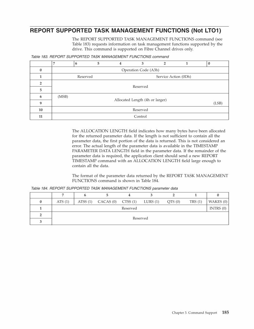
REPORT SUPPORTED TASK MANAGEMENT FUNCTIONS (Not LTO1)
The REPORT SUPPORTED TASK MANAGEMENT FUNCTIONS command (see
Table 183) requests information on task management functions supported by the
drive. This command is supported on Fibre Channel drives only.
Table 183. REPORT SUPPORTED TASK MANAGEMENT FUNCTIONS command
7 6 5 4 3 2 1 0
0 Operation Code (A3h)
1 Reserved Service Action (0Dh)
2
Reserved
5
6 (MSB)
Allocated Length (4h or larger)
9 (LSB)
10 Reserved
11 Control
The ALLOCATION LENGTH field indicates how many bytes have been allocated
for the returned parameter data. If the length is not sufficient to contain all the
parameter data, the first portion of the data is returned. This is not considered an
error. The actual length of the parameter data is available in the TIMESTAMP
PARAMETER DATA LENGTH field in the parameter data. If the remainder of the
parameter data is required, the application client should send a new REPORT
TIMESTAMP command with an ALLOCATION LENGTH field large enough to
contain all the data.
The format of the parameter data returned by the REPORT TASK MANAGEMENT
FUNCTIONS command is shown in Table 184.
Table 184. REPORT SUPPORTED TASK MANAGEMENT FUNCTIONS parameter data
7 6 5 4 3 2 1 0
0 ATS (1) ATSS (1) CACAS (0) CTSS (1) LURS (1) QTS (0) TRS (1) WAKES (0)
1 Reserved INTRS (0)
2
Reserved
3
Chapter 3. Command Support 185
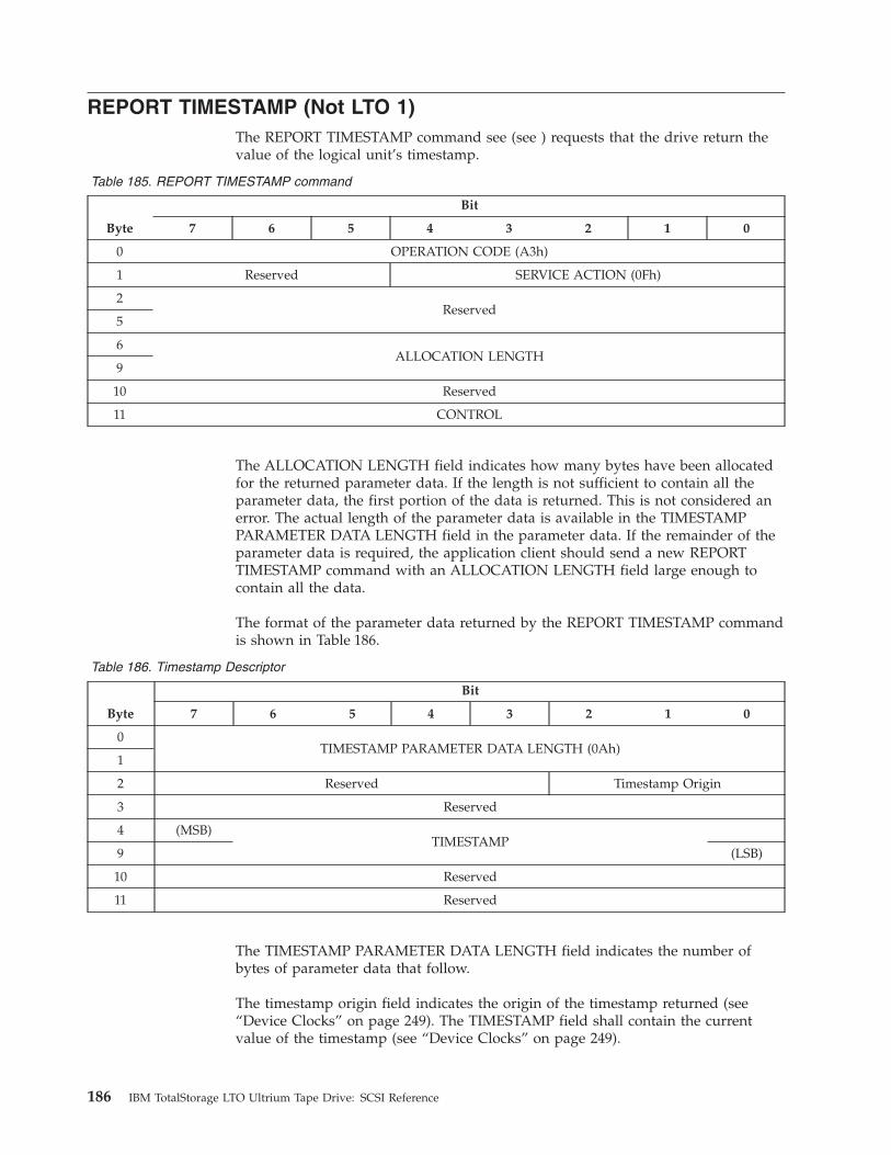
REPORT TIMESTAMP (Not LTO 1)
The REPORT TIMESTAMP command see (see ) requests that the drive return the
value of the logical unit’s timestamp.
Table 185. REPORT TIMESTAMP command
Byte
Bit
7 6 5 4 3 2 1 0
0 OPERATION CODE (A3h)
1 Reserved SERVICE ACTION (0Fh)
2
Reserved
5
6
ALLOCATION LENGTH
9
10 Reserved
11 CONTROL
The ALLOCATION LENGTH field indicates how many bytes have been allocated
for the returned parameter data. If the length is not sufficient to contain all the
parameter data, the first portion of the data is returned. This is not considered an
error. The actual length of the parameter data is available in the TIMESTAMP
PARAMETER DATA LENGTH field in the parameter data. If the remainder of the
parameter data is required, the application client should send a new REPORT
TIMESTAMP command with an ALLOCATION LENGTH field large enough to
contain all the data.
The format of the parameter data returned by the REPORT TIMESTAMP command
is shown in Table 186.
Table 186. Timestamp Descriptor
Byte
Bit
7 6 5 4 3 2 1 0
0
TIMESTAMP PARAMETER DATA LENGTH (0Ah)
1
2 Reserved Timestamp Origin
3 Reserved
4 (MSB)
TIMESTAMP
9 (LSB)
10 Reserved
11 Reserved
The TIMESTAMP PARAMETER DATA LENGTH field indicates the number of
bytes of parameter data that follow.
The timestamp origin field indicates the origin of the timestamp returned (see
“Device Clocks” on page 249). The TIMESTAMP field shall contain the current
value of the timestamp (see “Device Clocks” on page 249).
186 IBM TotalStorage LTO Ultrium Tape Drive: SCSI Reference
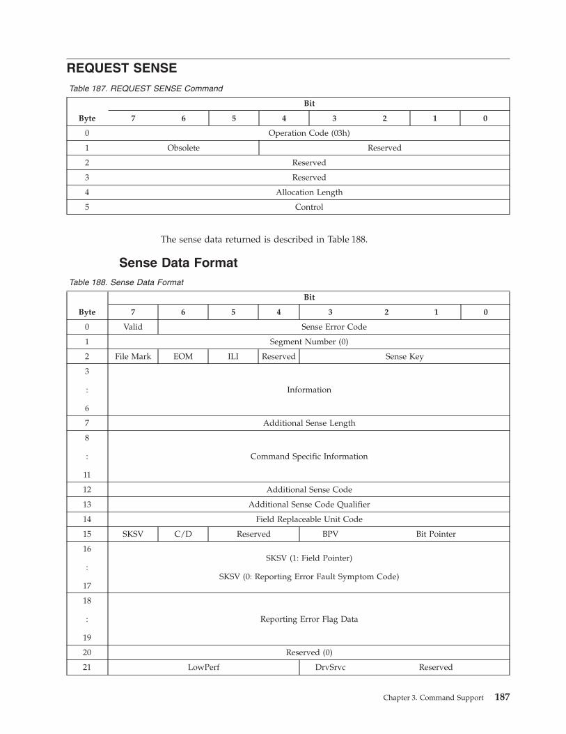
REQUEST SENSE
Table 187. REQUEST SENSE Command
Byte
Bit
7 6 5 4 3 2 1 0
0 Operation Code (03h)
1 Obsolete Reserved
2 Reserved
3 Reserved
4 Allocation Length
5 Control
The sense data returned is described in Table 188.
Sense Data Format
Table 188. Sense Data Format
Byte
Bit
7 6 5 4 3 2 1 0
0 Valid Sense Error Code
1 Segment Number (0)
2 File Mark EOM ILI Reserved Sense Key
3
:
6
Information
7 Additional Sense Length
8
:
11
Command Specific Information
12 Additional Sense Code
13 Additional Sense Code Qualifier
14 Field Replaceable Unit Code
15 SKSV C/D Reserved BPV Bit Pointer
16
:
17
SKSV (1: Field Pointer)
SKSV (0: Reporting Error Fault Symptom Code)
18
:
19
Reporting Error Flag Data
20 Reserved (0)
21 LowPerf DrvSrvc Reserved
Chapter 3. Command Support 187
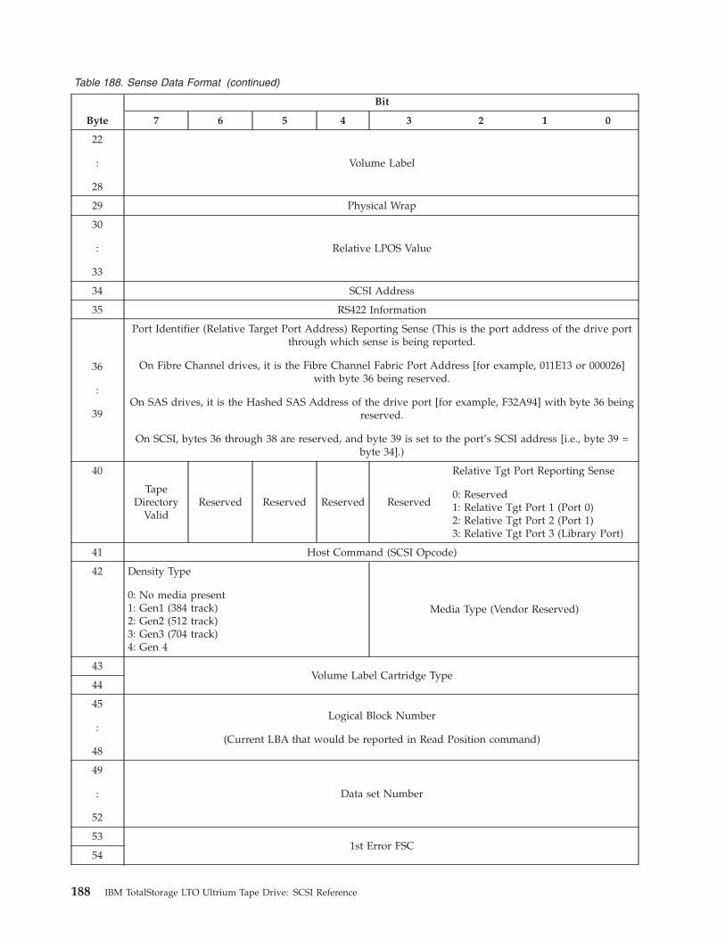
Table 188. Sense Data Format (continued)
Byte
Bit
7 6 5 4 3 2 1 0
22
:
28
Volume Label
29 Physical Wrap
30
:
33
Relative LPOS Value
34 SCSI Address
35 RS422 Information
36
:
39
Port Identifier (Relative Target Port Address) Reporting Sense (This is the port address of the drive port
through which sense is being reported.
On Fibre Channel drives, it is the Fibre Channel Fabric Port Address [for example, 011E13 or 000026]
with byte 36 being reserved.
On SAS drives, it is the Hashed SAS Address of the drive port [for example, F32A94] with byte 36 being
reserved.
On SCSI, bytes 36 through 38 are reserved, and byte 39 is set to the port’s SCSI address [i.e., byte 39 =
byte 34].)
40
Tape
Directory
Valid
Reserved Reserved Reserved Reserved
Relative Tgt Port Reporting Sense
0: Reserved1: Relative Tgt Port 1 (Port 0)2: Relative Tgt Port 2 (Port 1)3: Relative Tgt Port 3 (Library Port)
41 Host Command (SCSI Opcode)
42 Density Type
0: No media present1: Gen1 (384 track)2: Gen2 (512 track)3: Gen3 (704 track)4: Gen 4
Media Type (Vendor Reserved)
43
Volume Label Cartridge Type
44
45
:
48
Logical Block Number
(Current LBA that would be reported in Read Position command)
49
:
52
Data set Number
53
1st Error FSC
54
188 IBM TotalStorage LTO Ultrium Tape Drive: SCSI Reference
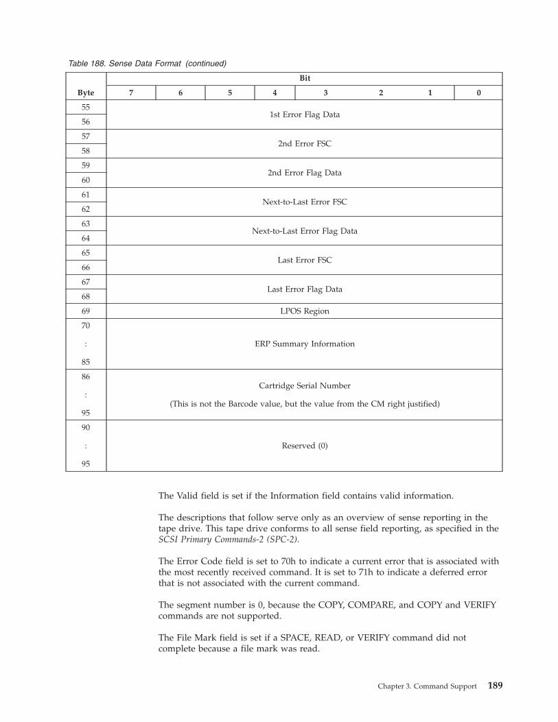
Table 188. Sense Data Format (continued)
Byte
Bit
7 6 5 4 3 2 1 0
55
1st Error Flag Data
56
57
2nd Error FSC
58
59
2nd Error Flag Data
60
61
Next-to-Last Error FSC
62
63
Next-to-Last Error Flag Data
64
65
Last Error FSC
66
67
Last Error Flag Data
68
69 LPOS Region
70
:
85
ERP Summary Information
86
:
95
Cartridge Serial Number
(This is not the Barcode value, but the value from the CM right justified)
90
:
95
Reserved (0)
The Valid field is set if the Information field contains valid information.
The descriptions that follow serve only as an overview of sense reporting in the
tape drive. This tape drive conforms to all sense field reporting, as specified in the
SCSI Primary Commands-2 (SPC-2).
The Error Code field is set to 70h to indicate a current error that is associated with
the most recently received command. It is set to 71h to indicate a deferred error
that is not associated with the current command.
The segment number is 0, because the COPY, COMPARE, and COPY and VERIFY
commands are not supported.
The File Mark field is set if a SPACE, READ, or VERIFY command did not
complete because a file mark was read.
Chapter 3. Command Support 189
The End of Medium (EOM) field is set if a WRITE or WRITE FILE MARKS
command completed in the early warning area. Spacing into BOM also causes this
field to be set. It is also set on an attempt to read or space past EOD or if an
attempt is made to space into Beginning of Media.
The Illegal Length Indicator (ILI) field is set if a READ or VERIFY ended because a
block was read from tape that did not have the block length requested in the
command.
For values of the Sense Key field see Chapter 7, “Sense Keys and Additional
Sense,” on page 253.
The Information Bytes are only valid if the Valid field is set. This occurs only for
current errors and not for deferred errors. See the specific command for details
about when Information Bytes are valid.
The Additional Sense Length is set to n-7, and is at least 10. When the sense data is
associated with an Illegal Length read, the Additional Sense Length may be 10. In
Generation 1 and Generation 2 drives, n can be as large as 35. In Generation 3
drives, n can be as large as 95. While this length in Generation 3 drives is not
anticipated to change, it is recommended that the Additional Sense Length be used
to parse that data.
The Command Specific Information is set to 0, because no supported commands
define a use for this field.
For supported Additional Sense Codes and Additional Sense Code Qualifiers, see
Chapter 7, “Sense Keys and Additional Sense,” on page 253.
The Field Replaceable Unit field is set to 0 or to a non-zero, vendor-specific code
that indicates the part of the drive that is suspected of causing the failure.
The only Sense Key-specific data supported is for Illegal Request (5h). For this
sense key, the Sense Key Specific Valid field is set and the following fields may be
set:
v The Command/Data (C/D) field is set to 1 if the illegal parameter was detected
in the Command Descriptor Block, and is set to 0 if it was detected in the Data
phase.
v If a bit within a byte was invalid, the Bit Pointer Valid (BPV) field is set and the
Bit Pointer field is set to indicate which bit was in error.
v The Field Pointer is set to indicate which byte was in error.
The Drive Service (DrvSrvc) bit is mapped to the “Dead Drive” flag of “Log Page
3Ch: Drive Usage Information” on page “Log Page 3Ch: Drive Usage Information”
on page 102. This bit is set to one by code whenever the drive determines that it
has a hardware fault causing the drive to be inoperative.
1. This bit is maintained across all reset conditions, firmware downloads, and
power cycles.
2. This bit does not affect drive operations.
3. The drive Power-On-Test does not test or affect this bit.
The Clean (CLN) field is set if the drive needs cleaning, and is otherwise set to 0.
190 IBM TotalStorage LTO Ultrium Tape Drive: SCSI Reference

In a Low Performance drive, the LowPerf bit is set to 1. In a normal,
non-performance limited drive, the LowPerf bit is set to 0.
The Dump field indicates that the drive has a Dump available. The field is used to
indicate when it is appropriate to read a dump.
The Volume Label Fields Valid (VolValid) field is set if the Volume Label being
reported is valid.
If a cartridge is loaded in the drive and the Volume Label Fields Valid is set, the
Volume Label field reports the seven characters from the left of the volume label
from the CM Mechanism Related Data page (if one exists), or it reports the seven
characters from the left of the volume label from the host bar code field in the CM
(if it exists), or it reports all spaces (ASCII 20h).
The Current Wrap reports the physical wrap of the tape. The least significant bit
reflects the current physical direction. A 0 means the current direction is away from
physical beginning of tape. A 1 means the current direction is towards physical
beginning of tape.
Relative LPOS reports the current physical position on tape.
SCSI Address reports the SCSI Bus Address for the drive. Values returned range
from 00h to 0Fh.
The RS422 Information field may contain a value passed across the RS-422 serial
interface by, for example, a tape library, if the library vendor chooses to send such
a value. The value passed from across the RS-422 interface is reported persistently
until a different value is sent, at which time the new value is reported persistently.
The Volume Label Cartridge Type is defined by Table 189.
Table 189. Volume Label Cartridge Type
Definition Native Capacity Volume Label Cartridge Type
Ultrium 1 Type A 100 GB L1
Ultrium 1 Type B 50 GB LA
Ultrium 1 Type C 30 GB LB
Ultrium 1 Type D 10 GB LC
Ultrium 2 Type A 200 GB L2
Ultrium 3 Type A 400 GB L3
Ultrium 3 WORM A 400 GB WORM LT
Ultrium 4 Type A 800 GB L4
Ultrium 4 WORM A 800 GB WORM LU
Chapter 3. Command Support 191
RESERVE UNIT
The RESERVE UNIT command creates a reservation for the drive. Third-party
reserves are not supported.
Table 190. 6-Byte RESERVE UNIT Command
Byte
Bit
7 6 5 4 3 2 1 0
0 Operation Code (16h)
1 Obsolete Obsolete (00h)
2 Reserved
3 Reserved
4 Reserved
5 Control
Table 191. 10-Byte RESERVE UNIT Command
Byte
Bit
7 6 5 4 3 2 1 0
0 Operation Code (56h)
1 Obsolete 3rdPty(0) Reserved LongID (0) Reserved
2 Reserved
3 Third Party Device ID (0)
4 Reserved
5 Reserved
6 Reserved
7
:
8
Parameter List Length (0)
9 Control
192 IBM TotalStorage LTO Ultrium Tape Drive: SCSI Reference
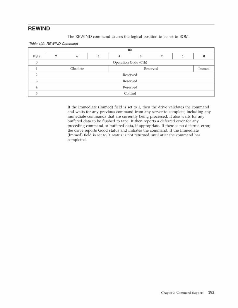
REWIND
The REWIND command causes the logical position to be set to BOM.
Table 192. REWIND Command
Byte
Bit
7 6 5 4 3 2 1 0
0 Operation Code (01h)
1 Obsolete Reserved Immed
2 Reserved
3 Reserved
4 Reserved
5 Control
If the Immediate (Immed) field is set to 1, then the drive validates the command
and waits for any previous command from any server to complete, including any
immediate commands that are currently being processed. It also waits for any
buffered data to be flushed to tape. It then reports a deferred error for any
preceding command or buffered data, if appropriate. If there is no deferred error,
the drive reports Good status and initiates the command. If the Immediate
(Immed) field is set to 0, status is not returned until after the command has
completed.
Chapter 3. Command Support 193

SECURITY PROTOCOL IN (SPIN) A2h
The SECURITY PROTOCOL IN command (see Table 193) is used to retrieve
security protocol information (see xx) or the results of one or more SECURITY
PROTOCOL OUT commands (see “SECURITY PROTOCOL OUT (SPOUT) B5h” on
page 203).
Table 193. Security Protocol In - A2h CDB
Byte
Bit
7 6 5 4 3 2 1 0
0 Operation code (A2h)
1 Security Protocol
2
Security Protocol Specific
3
4 INC_512
(0)
Reserved
5 Reserved
6 (MSB)
Allocation Length
9 (LSB)
10 Reserved
11 Control Byte (see ″Control Byte Definition″ on page xxx)
The following parameters apply:
v Security Protocol
Table 194. Security Protocol Definitions
Code Description Reference
00h
Security protocol information
“Security Protocol In Pages (00h
- Security Protocol Information)”
20h
Tape Data Encryption
“Security Protocol In Pages (20h
- Tape Data Encryption)” on
page 196
all others Reserved
v Security Protocol Specific - The contents depend on the protocol specified by the
Security Protocol field (see Table 194).
v Allocation Length
Security Protocol In Pages (00h - Security Protocol
Information)
The Security Protocol Specific field of the SPIN CDB is defined by Table 195.
Table 195. Security Protocol Specific Definitions for Security Protocol 00h
Code Description Reference
0000h
Supported security protocol list
“SPIN (00h:0000h) -
Supported Security Protocols
List” on page 195
0001h
Certificate data
“SPIN (00h:0001h) -
Certificate Data” on page 195
194 IBM TotalStorage LTO Ultrium Tape Drive: SCSI Reference

Table 195. Security Protocol Specific Definitions for Security Protocol 00h (continued)
Code Description Reference
0002h - FFFFh Reserved
SPIN (00h:0000h) - Supported Security Protocols List
If the SECURITY PROTOCOL field is set to 00h and the SECURITY PROTOCOL
SPECIFIC field is set to 0000h in a SECURITY PROTOCOL IN command, the
parameter data shall have the format shown in Table 196.
Table 196. Supported Security Protocols List Structure
Byte
Bit
7 6 5 4 3 2 1 0
0
Reserved
5
6 (MSB)
Supported Security Protocol List Length (m-7)
7 (LSB)
8 Supported Security Protocol (first) (00h)
.
.
.
m Supported Security Protocol (last)
The supported Security Protocols are listed in Table 194 on page 194.
SPIN (00h:0001h) - Certificate Data
The drive certificate (if present) is provided in X.509 format via this interface (see
SPC-4).
If the Security Protocol field is set to 00h and the Security Protocol Specific field is
set to 0001h in a Security Protocol In command, the parameter data shall have the
format shown in Table 197.
Table 197. Certificate Data Structure
Byte
Bit
7 6 5 4 3 2 1 0
0
Reserved
1
2 (MSB)
Certificate Length (m-3)
3 (LSB)
4
Certificate
m
The following parameters apply:
v Certificate Length - The total length, in bytes, of the certificate that follows.
v Certificate - The drive certificate set during manufacturing is returned.
Chapter 3. Command Support 195

Security Protocol In Pages (20h - Tape Data Encryption)
The Security Protocol Specific field (see Table 198) specifies the type of report that
the application client is requesting. Table 198 shows supported Security Protocol
Specific field values.
Table 198. Security Protocol Specific Definitions for Security Protocol 20h
Page Code Description Reference
0000h Tape Data Encryption In Support Pages see 196
0001h Tape Data Encryption Out Support Pages see 197
0010h Data Encryption Capabilities see 198
0011h Supported Key Formats see 199
0012h Data Encryption Management Capabilities see 199
0020h Data Encryption Status see 200
0021h Next Block Encryption Status see 201
SPIN (20h:0000h) - Tape Data Encryption In Support Pages page
Supported protocol specific in pages for protocol 20h are indicated above (see
SSC-3).
Table 199. 0000h - Tape Data Encryption In Support Pages Structure
Byte
Bit
7 6 5 4 3 2 1 0
0 (MSB)
Page Code (0000h)
1 (LSB)
2 (MSB)
Page Length (n-3)
3 (LSB)
Tape Data Encryption In Support page code list
4 (MSB)
Tape Data Encryption In Support page code (first)
5 (LSB)
...
n-1 (MSB)
Tape Data Encryption In Support page code (last)
n (LSB)
Table 200 show which Tape Data Encryption In page codes are supported:
Table 200. Tape Data Encryption In page codes
Page Code Description Reference
0000h Tape Data Encryption In Support Pages
“SPIN (20h:0000h) -
Tape Data Encryption
In Support Pages
page”
0001h Tape Data Encryption Out Support Pages
“SPIN (20h:0001h) -
Tape Data Encryption
Out Support Pages
page” on page 197
196 IBM TotalStorage LTO Ultrium Tape Drive: SCSI Reference
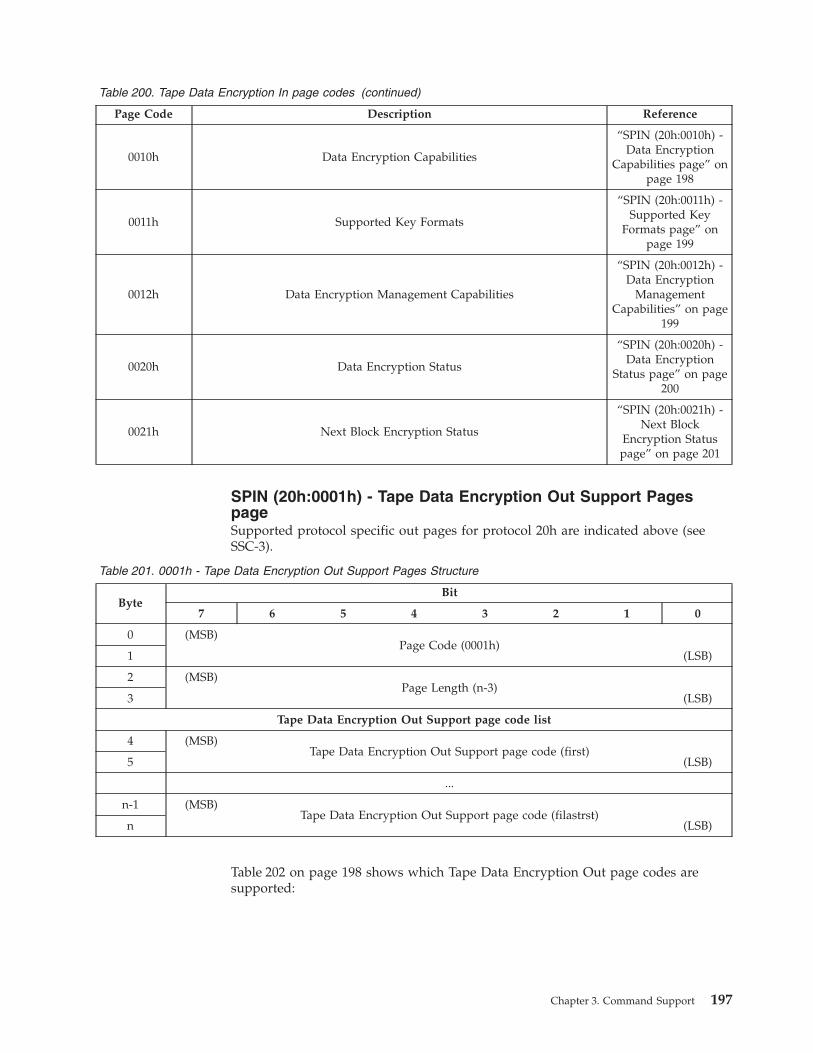
Table 200. Tape Data Encryption In page codes (continued)
Page Code Description Reference
0010h Data Encryption Capabilities
“SPIN (20h:0010h) -
Data Encryption
Capabilities page” on
page 198
0011h Supported Key Formats
“SPIN (20h:0011h) -
Supported Key
Formats page” on
page 199
0012h Data Encryption Management Capabilities
“SPIN (20h:0012h) -
Data Encryption
Management
Capabilities” on page
199
0020h Data Encryption Status
“SPIN (20h:0020h) -
Data Encryption
Status page” on page
200
0021h Next Block Encryption Status
“SPIN (20h:0021h) -
Next Block
Encryption Status
page” on page 201
SPIN (20h:0001h) - Tape Data Encryption Out Support Pages
page
Supported protocol specific out pages for protocol 20h are indicated above (see
SSC-3).
Table 201. 0001h - Tape Data Encryption Out Support Pages Structure
Byte
Bit
7 6 5 4 3 2 1 0
0 (MSB)
Page Code (0001h)
1 (LSB)
2 (MSB)
Page Length (n-3)
3 (LSB)
Tape Data Encryption Out Support page code list
4 (MSB)
Tape Data Encryption Out Support page code (first)
5 (LSB)
...
n-1 (MSB)
Tape Data Encryption Out Support page code (filastrst)
n (LSB)
Table 202 on page 198 shows which Tape Data Encryption Out page codes are
supported:
Chapter 3. Command Support 197

Table 202. Tape Data Encryption Out page codes
Page Code Description Reference
0010h Set Data Encryption “SPIN (20h:0010h) -
Data Encryption
Capabilities page”
SPIN (20h:0010h) - Data Encryption Capabilities page
Table 203 specifies the format of the Data Encryption Capabilities page.
Table 203. 0010h - Data Encryption Capabilities page
Byte
Bit
7 6 5 4 3 2 1 0
0 (MSB)
Page Code (0010h)
1 (LSB)
2 (MSB)
Page Length n-3)
3 (LSB)
4
Reserved
19
Data Encryption Algorithm descriptor list
20
Data Encryption Algorithm descriptor (first)
...
Data Encryption Algorithm descriptor (last)
n
Data Encryption Algorithm Descriptor - Standard Encryption
The Standard Encryption Algorithm Descriptor is shown in Table 204.
Table 204. Data Encryption Algorithm Descriptor - Standard Encryption Structure
Byte
Bit
7 6 5 4 3 2 1 0
0 Algorithm Index (01h)
1 Reserved
2 (MSB)
Descriptor Length (0014h)
3 (LSB)
4 AVFMV SDK_C (0) MAC_C (1) DED_C (1) DECRYPT_C (2H) ENCRYPT_C (2H)
5 Reserved NONCE_C (3) Reserved
6 (MSB) Maximum Unauthenticated Key-Associated Data (U-KAD) Bytes(0020h) 7 (LSB)
8 (MSB) Maximum Authenticated Key-Associated Data (A-KAD) Bytes(000Ch) 9 (LSB)
10 (MSB)
Key Size (0020h)
11 (LSB)
198 IBM TotalStorage LTO Ultrium Tape Drive: SCSI Reference
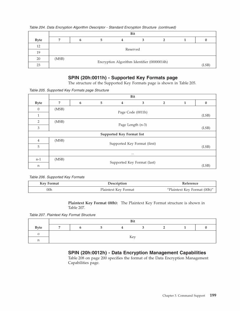
Table 204. Data Encryption Algorithm Descriptor - Standard Encryption Structure (continued)
Byte
Bit
7 6 5 4 3 2 1 0
12
Reserved
19
20 (MSB)
Encryption Algorithm Identifier (00000014h)
23 (LSB)
SPIN (20h:0011h) - Supported Key Formats page
The structure of the Supported Key Formats page is shown in Table 205.
Table 205. Supported Key Formats page Structure
Byte
Bit
7 6 5 4 3 2 1 0
0 (MSB)
Page Code (0011h)
1 (LSB)
2 (MSB)
Page Length (n-3)
3 (LSB)
Supported Key Format list
4 (MSB)
Supported Key Format (first)
5 (LSB)
...
n-1 (MSB)
Supported Key Format (last)
n (LSB)
Table 206. Supported Key Formats
Key Format Description Reference
00h Plaintext Key Format “Plaintext Key Format (00h)”
Plaintext Key Format (00h): The Plaintext Key Format structure is shown in
Table 207.
Table 207. Plaintext Key Format Structure
Byte
Bit
7 6 5 4 3 2 1 0
o
Key
n
SPIN (20h:0012h) - Data Encryption Management Capabilities
Table 208 on page 200 specifies the format of the Data Encryption Management
Capabilities page.
Chapter 3. Command Support 199

Table 208. Data Encryption Management Capabilities
Byte
Bit
7 6 5 4 3 2 1 0
0 (MSB)
Page Code (0012h)
1 (LSB)
2 (MSB)
Page Length (000Ch)
3 (LSB)
4 Reserved LOCK_C(1)
5
Reserved
CKOD_C(1)
CKORP_C(1)
CKORL_C(1)
6 Reserved
7
Reserved
AITN_C(1)
LOCAL_C(1)
PUBLIC_C(1)
8
Reserved
15
SPIN (20h:0020h) - Data Encryption Status page
Table 209 specifies the format of the Data Encryption Status page.
Note: This is a query of information which was set with Security Protocol Out
0010h - Set Data Encryption and does not reflect the actual state of the
medium itself or of any data on medium.
Table 209. 0020h - Data Encryption Status page
Byte
Bit
7 6 5 4 3 2 1 0
0 (MSB)
Page Code (0020h)
1 (LSB)
2 (MSB)
Page Length (n-3)
3 (LSB)
4 I_T Nexus Scope Reserved Key Scope
5 Encryption Mode
6 Decryption Mode
7 Algorithm Index
8 (MSB)
Key Instance Counter
11 (LSB)
12
Reserved
23
24
Key-Associated Data Descriptors List
n
The following parameters apply:
v I_T Nexus Scope
v Key Scope
200 IBM TotalStorage LTO Ultrium Tape Drive: SCSI Reference
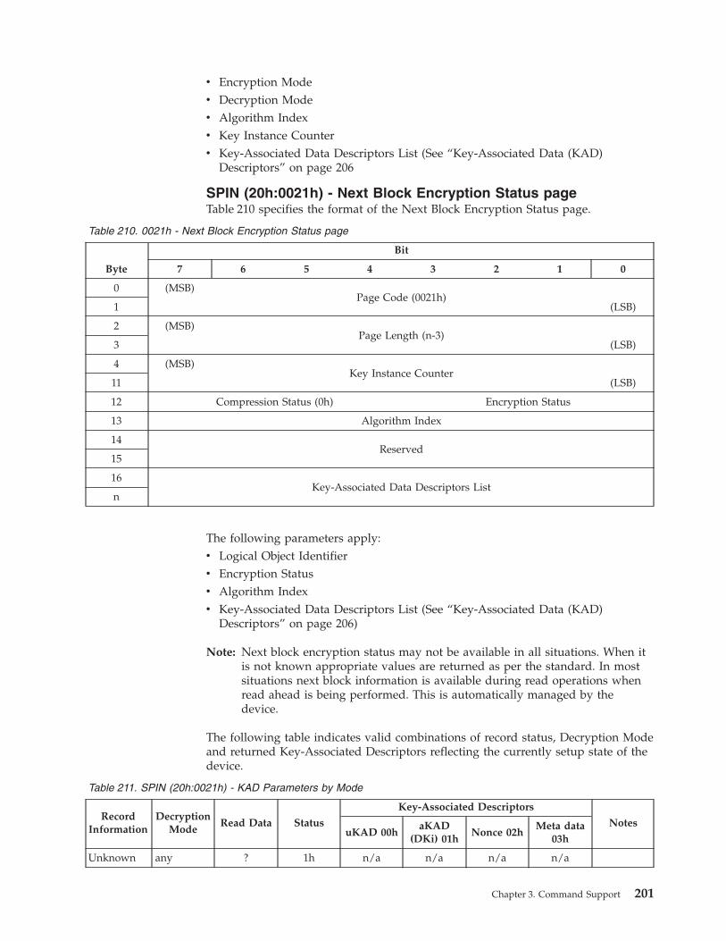
v Encryption Mode
v Decryption Mode
v Algorithm Index
v Key Instance Counter
v Key-Associated Data Descriptors List (See “Key-Associated Data (KAD)
Descriptors” on page 206
SPIN (20h:0021h) - Next Block Encryption Status page
Table 210 specifies the format of the Next Block Encryption Status page.
Table 210. 0021h - Next Block Encryption Status page
Byte
Bit
7 6 5 4 3 2 1 0
0 (MSB)
Page Code (0021h)
1 (LSB)
2 (MSB)
Page Length (n-3)
3 (LSB)
4 (MSB)
Key Instance Counter
11 (LSB)
12 Compression Status (0h) Encryption Status
13 Algorithm Index
14
Reserved
15
16
Key-Associated Data Descriptors List
n
The following parameters apply:
v Logical Object Identifier
v Encryption Status
v Algorithm Index
v Key-Associated Data Descriptors List (See “Key-Associated Data (KAD)
Descriptors” on page 206)
Note: Next block encryption status may not be available in all situations. When it
is not known appropriate values are returned as per the standard. In most
situations next block information is available during read operations when
read ahead is being performed. This is automatically managed by the
device.
The following table indicates valid combinations of record status, Decryption Mode
and returned Key-Associated Descriptors reflecting the currently setup state of the
device.
Table 211. SPIN (20h:0021h) - KAD Parameters by Mode
Record
Information
Decryption
Mode
Read Data Status
Key-Associated Descriptors
Notes
uKAD 00h
aKAD
(DKi) 01h
Nonce 02h
Meta data
03h
Unknown any ? 1h n/a n/a n/a n/a
Chapter 3. Command Support 201

Table 211. SPIN (20h:0021h) - KAD Parameters by Mode (continued)
Record
Information
Decryption
Mode
Read Data Status
Key-Associated Descriptors
Notes
uKAD 00h
aKAD
(DKi) 01h
Nonce 02h
Meta data
03h
Filemark any n/a 2h n/a n/a n/a n/a2 may be
unknown
EOD any n/a 2h n/a n/a n/a n/a may be
unknown
Error any n/a 1h n/a n/a n/a n/a may be
unknown
Cleartext 0h Disable C 3h n/a n/a n/a n/a
Cleartext 1h Raw E 3h n/a n/a n/a n/a not
readable
Cleartext 2h Decrypt E 3h n/a n/a n/a n/a not
readable
Cleartext 3h Mixed C 3h n/a n/a n/a n/a
Encrypted 0h Disable E 4h Y Y N N not
readable
Encrypted 1h Raw R 5h N N N Y
Encrypted 2h Decrypt C1 or Y Y N N
Encrypted 3h Mixed C1 6h Y Y N N
Legend:
Y: element is required
O: element is optional
N: element is not present
n/a: not applicable (element is not present)
C: cleartext (not encrypted)
R: raw (compressed encoded/encrypted)
E: error condition, record cannot be read
Notes:
1. Data is decrypted
2. Value may be returned if raw mode and data set is
encrypted
Key-Associated Data (KAD) Descriptors
See “Key-Associated Data (KAD) Descriptors” on page 206.
202 IBM TotalStorage LTO Ultrium Tape Drive: SCSI Reference
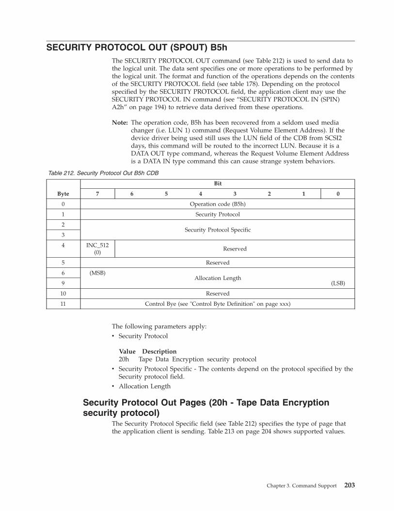
SECURITY PROTOCOL OUT (SPOUT) B5h
The SECURITY PROTOCOL OUT command (see Table 212) is used to send data to
the logical unit. The data sent specifies one or more operations to be performed by
the logical unit. The format and function of the operations depends on the contents
of the SECURITY PROTOCOL field (see table 178). Depending on the protocol
specified by the SECURITY PROTOCOL field, the application client may use the
SECURITY PROTOCOL IN command (see “SECURITY PROTOCOL IN (SPIN)
A2h” on page 194) to retrieve data derived from these operations.
Note: The operation code, B5h has been recovered from a seldom used media
changer (i.e. LUN 1) command (Request Volume Element Address). If the
device driver being used still uses the LUN field of the CDB from SCSI2
days, this command will be routed to the incorrect LUN. Because it is a
DATA OUT type command, whereas the Request Volume Element Address
is a DATA IN type command this can cause strange system behaviors.
Table 212. Security Protocol Out B5h CDB
Byte
Bit
7 6 5 4 3 2 1 0
0 Operation code (B5h)
1 Security Protocol
2
Security Protocol Specific
3
4 INC_512
(0)
Reserved
5 Reserved
6 (MSB)
Allocation Length
9 (LSB)
10 Reserved
11 Control Bye (see "Control Byte Definition" on page xxx)
The following parameters apply:
v Security Protocol
Value Description
20h Tape Data Encryption security protocol
v Security Protocol Specific - The contents depend on the protocol specified by the
Security protocol field.
v Allocation Length
Security Protocol Out Pages (20h - Tape Data Encryption
security protocol)
The Security Protocol Specific field (see Table 212) specifies the type of page that
the application client is sending. Table 213 on page 204 shows supported values.
Chapter 3. Command Support 203
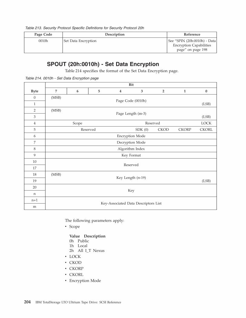
Table 213. Security Protocol Specific Definitions for Security Protocol 20h
Page Code Description Reference
0010h Set Data Encryption See “SPIN (20h:0010h) - Data
Encryption Capabilities
page” on page 198
SPOUT (20h:0010h) - Set Data Encryption
Table 214 specifies the format of the Set Data Encryption page.
Table 214. 0010h - Set Data Encryption page
Byte
Bit
7 6 5 4 3 2 1 0
0 (MSB)
Page Code (0010h)
1 (LSB)
2 (MSB)
Page Length (m-3)
3 (LSB)
4 Scope Reserved LOCK
5 Reserved SDK (0) CKOD CKORP CKORL
6 Encryption Mode
7 Decryption Mode
8 Algorithm Index
9 Key Format
10
Reserved
17
18 (MSB)
Key Length (n-19)
19 (LSB)
20
Key
n
n+1
Key-Associated Data Descriptors List
m
The following parameters apply:
v Scope
Value Description
0h Public
1h Local
2h All I_T Nexus
v LOCK
v CKOD
v CKORP
v CKORL
v Encryption Mode
204 IBM TotalStorage LTO Ultrium Tape Drive: SCSI Reference
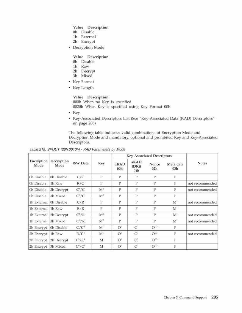
Value Description
0h Disable
1h External
2h Encrypt
v Decryption Mode
Value Description
0h Disable
1h Raw
2h Decrypt
3h Mixed
v Key Format
v Key Length
Value Description
000h When no Key is specified
0020h When Key is specified using Key Format 00h
v Key
v Key-Associated Descriptors List (See “Key-Associated Data (KAD) Descriptors”
on page 206)
The following table indicates valid combinations of Encryption Mode and
Decryption Mode and mandatory, optional and prohibited Key and Key-Associated
Descriptors.
Table 215. SPOUT (20h:0010h) - KAD Parameters by Mode
Encryption
Mode
Decryption
Mode
R/W Data Key
Key-Associated Descriptors
Notes uKAD00h
aKAD(DKi)01h
Nonce02h
Meta data03h
0h Disable 0h Disable C/C P P P P P
0h Disable 1h Raw R/C P P P P P not recommended
0h Disable 2h Decrypt C4/C M2 P P P P not recommended
0h Disable 3h Mixed C6/C M2 P P P P
1h External 0h Disable C/R P P P P M1 not recommended
1h External 1h Raw R/R P P P P M1
1h External 2h Decrypt C4/R M2 P P P M1 not recommended
1h External 3h Mixed C6/R M2 P P P M1 not recommended
2h Encrypt 0h Disable C/C4 M1 O1 O1 O1,3 P
2h Encrypt 1h Raw R/C4 M1 O1 O1 O1,3 P not recommended
2h Encrypt 2h Decrypt C5/C4 M O1 O1 O1,3 P
2h Encrypt 3h Mixed C6/C4 M O1 O1 O1,3 P
Chapter 3. Command Support 205
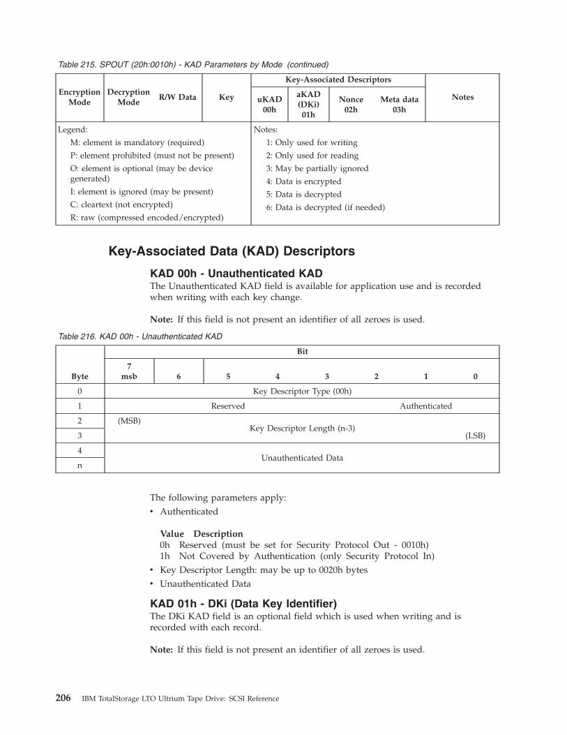
Table 215. SPOUT (20h:0010h) - KAD Parameters by Mode (continued)
Encryption
Mode
Decryption
Mode
R/W Data Key
Key-Associated Descriptors
Notes uKAD00h
aKAD(DKi)01h
Nonce02h
Meta data03h
Legend:
M: element is mandatory (required)
P: element prohibited (must not be present)
O: element is optional (may be device
generated)
I: element is ignored (may be present)
C: cleartext (not encrypted)
R: raw (compressed encoded/encrypted)
Notes:
1: Only used for writing
2: Only used for reading
3: May be partially ignored
4: Data is encrypted
5: Data is decrypted
6: Data is decrypted (if needed)
Key-Associated Data (KAD) Descriptors
KAD 00h - Unauthenticated KAD
The Unauthenticated KAD field is available for application use and is recorded
when writing with each key change.
Note: If this field is not present an identifier of all zeroes is used.
Table 216. KAD 00h - Unauthenticated KAD
Byte
Bit
7msb 6 5 4 3 2 1 0
0 Key Descriptor Type (00h)
1 Reserved Authenticated
2 (MSB)
Key Descriptor Length (n-3)
(LSB) 3
4
Unauthenticated Data
n
The following parameters apply:
v Authenticated
Value Description
0h Reserved (must be set for Security Protocol Out - 0010h)
1h Not Covered by Authentication (only Security Protocol In)
v Key Descriptor Length: may be up to 0020h bytes
v Unauthenticated Data
KAD 01h - DKi (Data Key Identifier)
The DKi KAD field is an optional field which is used when writing and is
recorded with each record.
Note: If this field is not present an identifier of all zeroes is used.
206 IBM TotalStorage LTO Ultrium Tape Drive: SCSI Reference
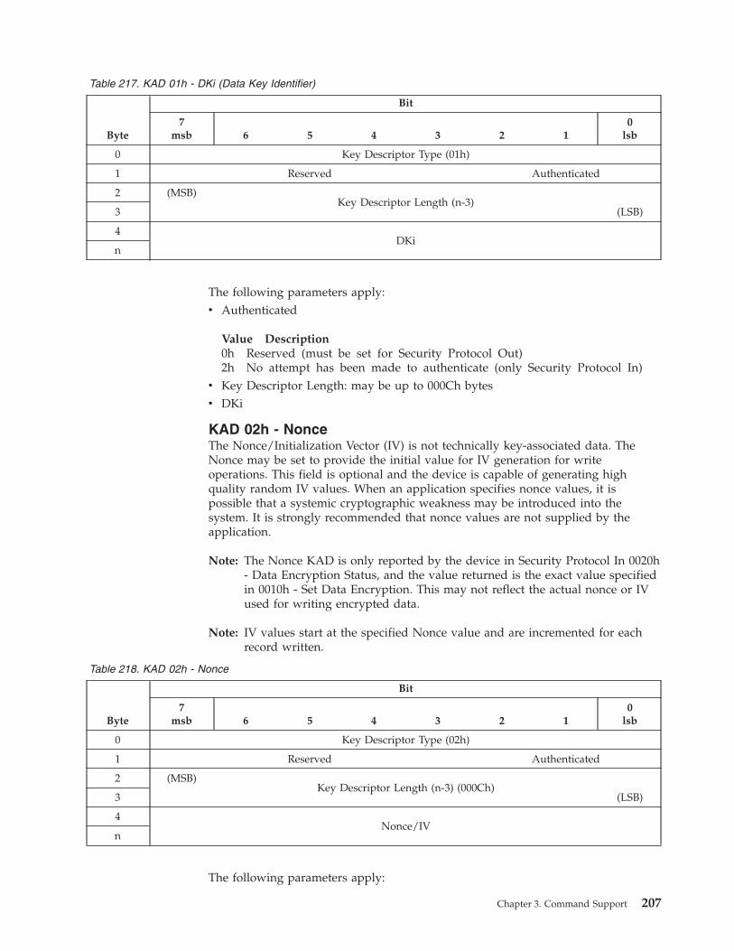
Table 217. KAD 01h - DKi (Data Key Identifier)
Byte
Bit
7msb 6 5 4 3 2 1
0lsb
0 Key Descriptor Type (01h)
1 Reserved Authenticated
2 (MSB)
Key Descriptor Length (n-3)
(LSB) 3
4
DKi
n
The following parameters apply:
v Authenticated
Value Description
0h Reserved (must be set for Security Protocol Out)
2h No attempt has been made to authenticate (only Security Protocol In)
v Key Descriptor Length: may be up to 000Ch bytes
v DKi
KAD 02h - Nonce
The Nonce/Initialization Vector (IV) is not technically key-associated data. The
Nonce may be set to provide the initial value for IV generation for write
operations. This field is optional and the device is capable of generating high
quality random IV values. When an application specifies nonce values, it is
possible that a systemic cryptographic weakness may be introduced into the
system. It is strongly recommended that nonce values are not supplied by the
application.
Note: The Nonce KAD is only reported by the device in Security Protocol In 0020h
- Data Encryption Status, and the value returned is the exact value specified
in 0010h - Set Data Encryption. This may not reflect the actual nonce or IV
used for writing encrypted data.
Note: IV values start at the specified Nonce value and are incremented for each
record written.
Table 218. KAD 02h - Nonce
Byte
Bit
7msb 6 5 4 3 2 1
0lsb
0 Key Descriptor Type (02h)
1 Reserved Authenticated
2 (MSB)
Key Descriptor Length (n-3) (000Ch)
(LSB) 3
4
Nonce/IV
n
The following parameters apply:
Chapter 3. Command Support 207
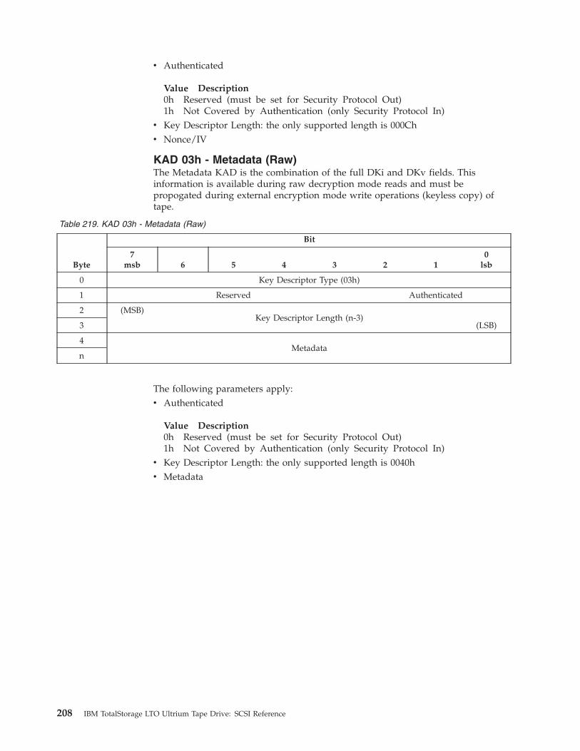
v Authenticated
Value Description
0h Reserved (must be set for Security Protocol Out)
1h Not Covered by Authentication (only Security Protocol In)
v Key Descriptor Length: the only supported length is 000Ch
v Nonce/IV
KAD 03h - Metadata (Raw)
The Metadata KAD is the combination of the full DKi and DKv fields. This
information is available during raw decryption mode reads and must be
propogated during external encryption mode write operations (keyless copy) of
tape.
Table 219. KAD 03h - Metadata (Raw)
Byte
Bit
7msb 6 5 4 3 2 1
0lsb
0 Key Descriptor Type (03h)
1 Reserved Authenticated
2 (MSB)
Key Descriptor Length (n-3)
(LSB) 3
4
Metadata
n
The following parameters apply:
v Authenticated
Value Description
0h Reserved (must be set for Security Protocol Out)
1h Not Covered by Authentication (only Security Protocol In)
v Key Descriptor Length: the only supported length is 0040h
v Metadata
208 IBM TotalStorage LTO Ultrium Tape Drive: SCSI Reference
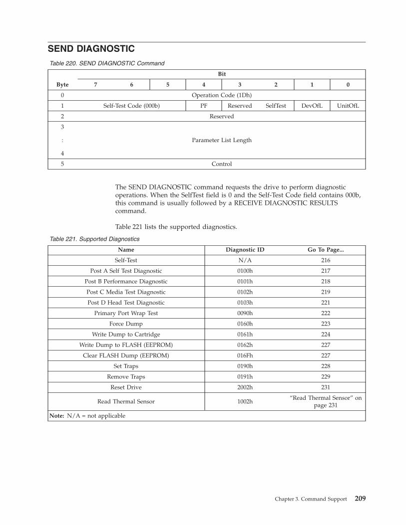
SEND DIAGNOSTIC
Table 220. SEND DIAGNOSTIC Command
Byte
Bit
7 6 5 4 3 2 1 0
0 Operation Code (1Dh)
1 Self-Test Code (000b) PF Reserved SelfTest DevOfL UnitOfL
2 Reserved
3
:
4
Parameter List Length
5 Control
The SEND DIAGNOSTIC command requests the drive to perform diagnostic
operations. When the SelfTest field is 0 and the Self-Test Code field contains 000b,
this command is usually followed by a RECEIVE DIAGNOSTIC RESULTS
command.
Table 221 lists the supported diagnostics.
Table 221. Supported Diagnostics
Name Diagnostic ID Go To Page...
Self-Test N/A 216
Post A Self Test Diagnostic 0100h 217
Post B Performance Diagnostic 0101h 218
Post C Media Test Diagnostic 0102h 219
Post D Head Test Diagnostic 0103h 221
Primary Port Wrap Test 0090h 222
Force Dump 0160h 223
Write Dump to Cartridge 0161h 224
Write Dump to FLASH (EEPROM) 0162h 227
Clear FLASH Dump (EEPROM) 016Fh 227
Set Traps 0190h 228
Remove Traps 0191h 229
Reset Drive 2002h 231
Read Thermal Sensor 1002h
“Read Thermal Sensor” on
page 231
Note: N/A = not applicable
Chapter 3. Command Support 209
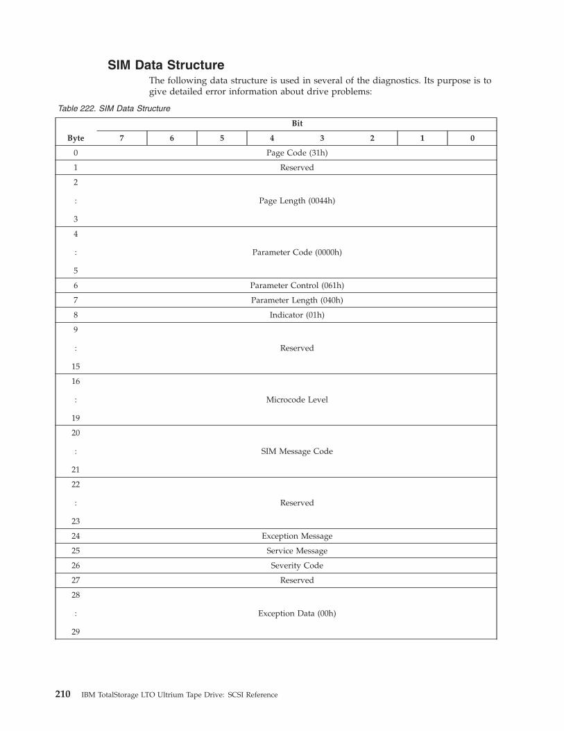
SIM Data Structure
The following data structure is used in several of the diagnostics. Its purpose is to
give detailed error information about drive problems:
Table 222. SIM Data Structure
Byte
Bit
7 6 5 4 3 2 1 0
0 Page Code (31h)
1 Reserved
2
:
3
Page Length (0044h)
4
:
5
Parameter Code (0000h)
6 Parameter Control (061h)
7 Parameter Length (040h)
8 Indicator (01h)
9
:
15
Reserved
16
:
19
Microcode Level
20
:
21
SIM Message Code
22
:
23
Reserved
24 Exception Message
25 Service Message
26 Severity Code
27 Reserved
28
:
29
Exception Data (00h)
210 IBM TotalStorage LTO Ultrium Tape Drive: SCSI Reference
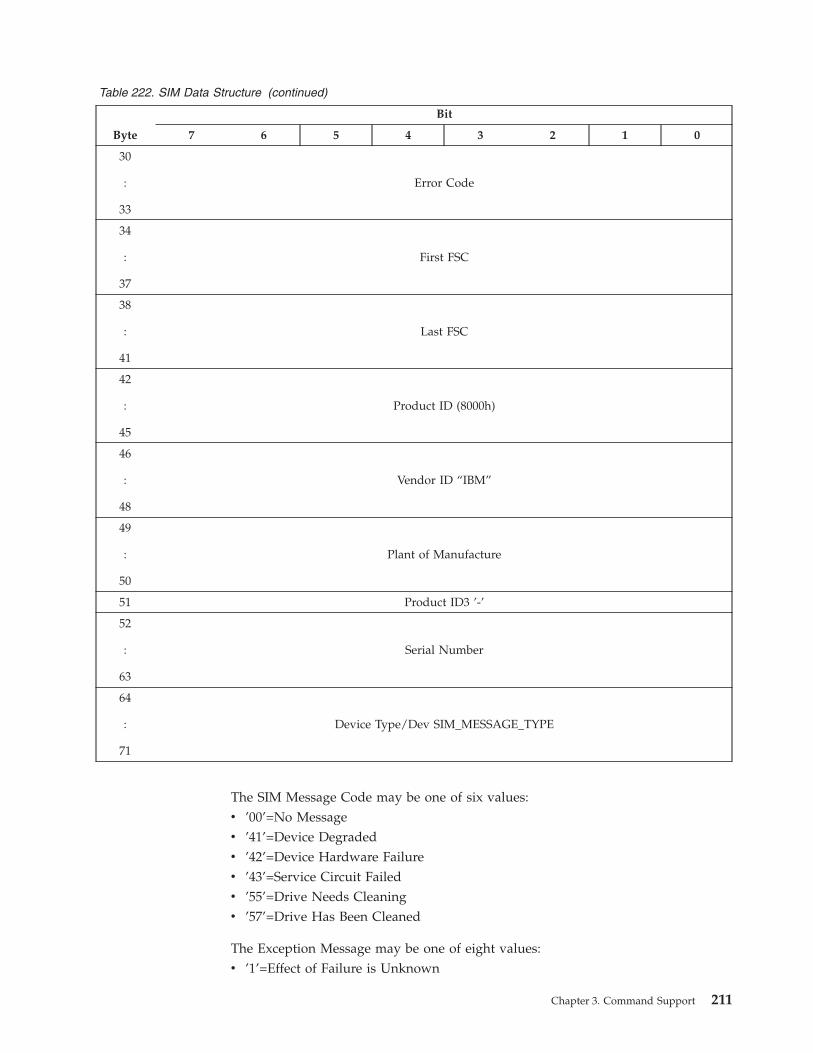
Table 222. SIM Data Structure (continued)
Byte
Bit
7 6 5 4 3 2 1 0
30
:
33
Error Code
34
:
37
First FSC
38
:
41
Last FSC
42
:
45
Product ID (8000h)
46
:
48
Vendor ID “IBM”
49
:
50
Plant of Manufacture
51 Product ID3 ’-’
52
:
63
Serial Number
64
:
71
Device Type/Dev SIM_MESSAGE_TYPE
The SIM Message Code may be one of six values:
v ’00’=No Message
v ’41’=Device Degraded
v ’42’=Device Hardware Failure
v ’43’=Service Circuit Failed
v ’55’=Drive Needs Cleaning
v ’57’=Drive Has Been Cleaned
The Exception Message may be one of eight values:
v ’1’=Effect of Failure is Unknown
Chapter 3. Command Support 211
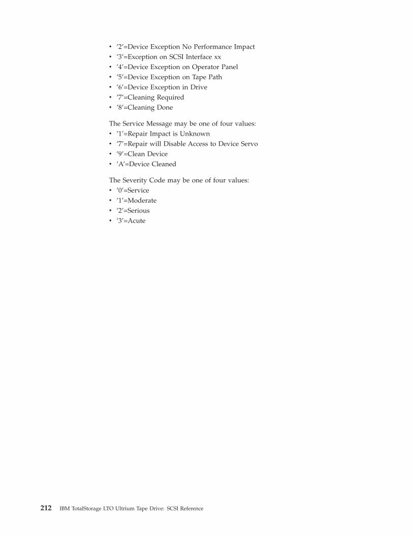
v ’2’=Device Exception No Performance Impact
v ’3’=Exception on SCSI Interface xx
v ’4’=Device Exception on Operator Panel
v ’5’=Device Exception on Tape Path
v ’6’=Device Exception in Drive
v ’7’=Cleaning Required
v ’8’=Cleaning Done
The Service Message may be one of four values:
v ’1’=Repair Impact is Unknown
v ’7’=Repair will Disable Access to Device Servo
v ’9’=Clean Device
v ’A’=Device Cleaned
The Severity Code may be one of four values:
v ’0’=Service
v ’1’=Moderate
v ’2’=Serious
v ’3’=Acute
212 IBM TotalStorage LTO Ultrium Tape Drive: SCSI Reference
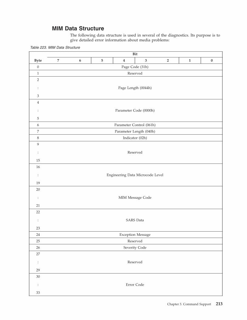
MIM Data Structure
The following data structure is used in several of the diagnostics. Its purpose is to
give detailed error information about media problems:
Table 223. MIM Data Structure
Byte
Bit
7 6 5 4 3 2 1 0
0 Page Code (31h)
1 Reserved
2
:
3
Page Length (0044h)
4
:
5
Parameter Code (0000h)
6 Parameter Control (061h)
7 Parameter Length (040h)
8 Indicator (02h)
9
:
15
Reserved
16
:
19
Engineering Data Microcode Level
20
:
21
MIM Message Code
22
:
23
SARS Data
24 Exception Message
25 Reserved
26 Severity Code
27
:
29
Reserved
30
:
33
Error Code
Chapter 3. Command Support 213

Table 223. MIM Data Structure (continued)
Byte
Bit
7 6 5 4 3 2 1 0
34
:
39
Volume ID Volume Serial Number
40 Volume ID Flag
41 Reserved
42
:
45
Product ID (8000h)
46
:
48
Vendor ID “IBM”
49
:
50
Plant of Manufacture
51 Product ID3 ’-’
52
:
63
Serial Number
64
:
71
Device Type
The MIM Message Code may be one of four values:
v ’00’=No Message
v ’60’=Bad Media Read Only Permitted
v ’61’=Rewrite Media if Possible
v ’72’=Replace Cleaning Cartridge
The Exception Message may be one of four values:
v ’2’=Data Degraded
v ’4’=Medium Degraded
v ’6’=CM Error
v ’7’=Medium Exception
The Severity Code may be one of four values:
v ’0’=Service
v ’1’=Moderate - Temporary Read/Write Errors
v ’2’=Serious - Permanent Read/Write Errors
214 IBM TotalStorage LTO Ultrium Tape Drive: SCSI Reference
v ’3’=Acute - CM Error
The Volume ID Flag may be one of four values:
v ’0’=VOLID not valid
v ’1’=VOLID valid - obtained from tape (CM)
v ’3’=VOLID valid - obtained from cartridge label (server data)
v ’5’=VOLID valid - obtained from cartridge level (library)
Chapter 3. Command Support 215
Self-Test
For the Self-Test Diagnostic, the CDB values must be set as follows:
v PF - Any value allowed and ignored
v SelfTest - 1
v DevOfl - Any value allowed and ignored
v UnitOfl - Any value allowed and ignored
v Parameter List Length - 0000h
Receive Diagnostics Results: There are no diagnostic results for the Self-Test
diagnostic.
216 IBM TotalStorage LTO Ultrium Tape Drive: SCSI Reference
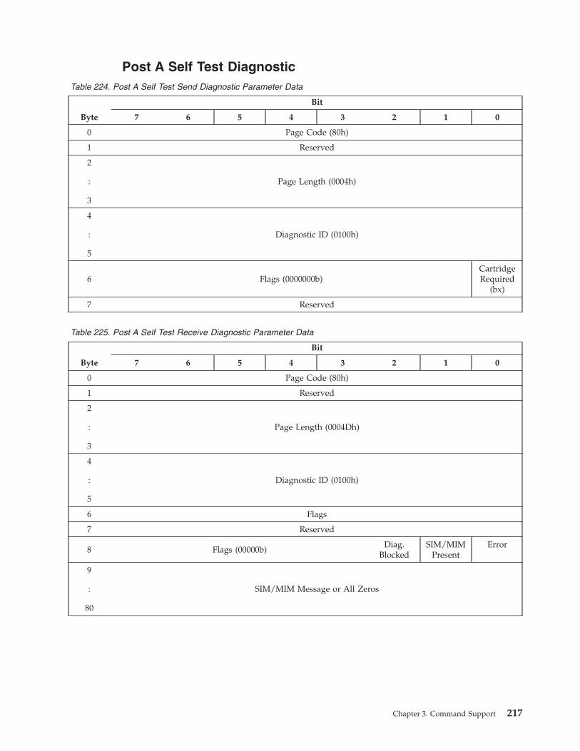
Post A Self Test Diagnostic
Table 224. Post A Self Test Send Diagnostic Parameter Data
Byte
Bit
7 6 5 4 3 2 1 0
0 Page Code (80h)
1 Reserved
2
:
3
Page Length (0004h)
4
:
5
Diagnostic ID (0100h)
6 Flags (0000000b)
Cartridge
Required
(bx)
7 Reserved
Table 225. Post A Self Test Receive Diagnostic Parameter Data
Byte
Bit
7 6 5 4 3 2 1 0
0 Page Code (80h)
1 Reserved
2
:
3
Page Length (0004Dh)
4
:
5
Diagnostic ID (0100h)
6 Flags
7 Reserved
8 Flags (00000b)
Diag.
Blocked
SIM/MIM
Present
Error
9
:
80
SIM/MIM Message or All Zeros
Chapter 3. Command Support 217
Post B Performance Diagnostic
The Performance Diagnostic performs a test to determine how well the tape drive
writes data. If the percentage degradation exceeds the threshold, the Send
Diagnostic command will return a Check Condition. The Sense Key will be set to
1h and the ASC/ASCQ set to 0000h. The FSC field of sense data will be set to
52E5, if the degradation is in the forward direction, or 52E6, if the degradation was
in the backward direction. The Flag field of the sense data will be set to the
percentage. TapeAlert2 (Write Warning) will be set and the SCD will display the
character ’A.’ The Receive Diagnostic command will return SIM data related to the
failure.
Table 226. Post B Performance Send Diagnostic Parameter Data
Byte
Bit
7 6 5 4 3 2 1 0
0 Page Code (80h)
1 Reserved
2
:
3
Page Length (0004h)
4
:
5
Diagnostic ID (0101h)
6 Flags (0000000b)
Cartridge
Required
(1b)
7 Reserved
Table 227. Post B Performance Receive Diagnostic Parameter Data
Byte
Bit
7 6 5 4 3 2 1 0
0 Page Code (80h)
1 Reserved
2
:
3
Page Length (0004Dh)
4
:
5
Diagnostic ID (0101h)
6 Flags
7 Reserved
8 Flags (00000b)
Diag.
Blocked
SIM/MIM
Present
Error
218 IBM TotalStorage LTO Ultrium Tape Drive: SCSI Reference

Table 227. Post B Performance Receive Diagnostic Parameter Data (continued)
Byte
Bit
7 6 5 4 3 2 1 0
9
:
80
SIM/MIM Message or All Zeros
Post C Media Test Diagnostic
Table 228. Post C Media Test Send Diagnostic Parameter Data
Byte
Bit
7 6 5 4 3 2 1 0
0 Page Code (80h)
1 Reserved
2
:
3
Page Length (0004h)
4
:
5
Diagnostic ID (0102h)
6 Flags (0000000b)
Cartridge
Required
(1b)
7 Reserved
Table 229. Post C Media Test Receive Diagnostic Parameter Data
Byte
Bit
7 6 5 4 3 2 1 0
0 Page Code (80h)
1 Reserved
2
:
3
Page Length (004Dh)
4
:
5
Diagnostic ID (0102h)
6 Flags
7 Reserved
8 Flags (00000b)
Diag.
Blocked
SIM/MIM
Present
Error
Chapter 3. Command Support 219

Table 229. Post C Media Test Receive Diagnostic Parameter Data (continued)
Byte
Bit
7 6 5 4 3 2 1 0
9
:
80
SIM/MIM Message or All Zeros
220 IBM TotalStorage LTO Ultrium Tape Drive: SCSI Reference

Post D Head Test Diagnostic
Table 230. Post D Head Test Send Diagnostic Parameter Data
Byte
Bit
7 6 5 4 3 2 1 0
0 Page Code (80h)
1 Reserved
2
:
3
Page Length (0004h)
4
:
5
Diagnostic ID (0103h)
6 Flags (0000000b)
Cartridge
Required
(1b)
7 Reserved
Table 231. Post D Head Test Receive Diagnostic Parameter Data
Byte
Bit
7 6 5 4 3 2 1 0
0 Page Code (80h)
1 Reserved
2
:
3
Page Length (004Dh)
4
:
5
Diagnostic ID (0103h)
6 Flags
7 Reserved
8 Flags (00000b)
Diag.
Blocked
SIM/MIM
Present
Error
9
:
80
SIM/MIM Message or All Zeros
Chapter 3. Command Support 221
Primary Port Wrap Test Diagnostic
This test will perform a wrap test on the specified primary port. A wrap tool must
be attached prior to running this command.
See Table 232.
Table 232. Primary Port Wrap Test Send Diagnostic Parameter Data
Byte 7 6 5 4 3 2 1 0
0 Page Code (80h)
1 Reserved
2 (MSB)
Page Length (0004h)
3 (LSB)
4
Diagnostic ID (0090h)
5
6 Flags (0000000b)
Cartridge
Required
(0b)
7 Port Identifier
Port Identifier
This field is synonymous with the Port Identifier field described in the Device
Identification Inquiry page. If the value of the Port Identifier is zero, then the wrap
test will be performed on all primary ports. If the value is a valid Port Identifier,
the wrap test is performed on the port indicated by the Port Identifier. If an invalid
Port Identifier value is used, the drive will respond with a Check Condition for
Invalid Field in Parameter List.
The Primary Port Wrap Test Receive Diagnostic returns information about the
attempted Primary Port Wrap Test Send Diagnostic.
Table 233. Primary Port Wrap Test Receive Diagnostic Parameter Data
Byte 7 6 5 4 3 2 1 0
0 Page Code (80h)
1 Reserved
2 (MSB)
Page Length (004Dh)
3 (LSB)
4
Diagnostic ID (0090h)
5
6 Flags
7 Reserved
8 Flags (00000b)
Diag.
Blocked
SIM/MIM
Present
Error
9
SIM/MIM Message or All Zeros
80
222 IBM TotalStorage LTO Ultrium Tape Drive: SCSI Reference
Force Dump
The Force Dump Diagnostic causes the drive to capture into a reserved space in
memory a log of data that is used to assist field and development engineers in
determining the root cause of drive behavior. This log is called a drive dump. This
diagnostic copies the dump to memory, but does not save it for later use. The save
operation must be done by using a READ BUFFER command or a Write Dump To
Cartridge Diagnostic.
Note: Because forcing a drive dump will overwrite any previously stored dump,
before forcing the dump it may be desirable to check the Dump field of the
sense data to determine if a drive dump exists.
For the Force Dump Diagnostic, the CDB values should be set as follows:
v PF - 1
v SelfTest - 0
v DevOfl - Any value allowed and ignored
v UnitOfl - Any value allowed and ignored
v Parameter List Length - 0008h
Table 234 shows the parameter data to be sent with the Force Dump diagnostic.
Table 234. Force Dump Diagnostic Parameter Data
Byte
Bit
7 6 5 4 3 2 1 0
0 Page Code (80h)
1 Reserved
2
:
3
Page Length (0004h)
4
:
5
Diagnostic ID (0160h)
6 Flags (0000000b)
Cartridge
Required
(0)
7 Reserved
Receive Diagnostics Results: There are no diagnostic results for the Force Dump
diagnostic.
Chapter 3. Command Support 223
Write Dump To Cartridge
The Write Dump To Cartridge Send Diagnostic causes the drive to write a dump
from memory to the cartridge that is loaded in the drive. The dump might exist
because of a previous Force Dump diagnostic command or it might exist because
of other scenarios where the drive code automatically creates a dump. To
determine if a drive dump exists before forcing a dump, the application client can
look at the Dump field of the sense data.
Table 235. Write Dump to Cartridge Send Diagnostic Parameter Data
Byte
Bit
7 6 5 4 3 2 1 0
0 Page Code (80h)
1 Reserved
2
:
3
Page Length (0004h)
4
:
5
Diagnostic ID (0161h)
6 Flags (0000000b)
Cartridge
Required
(1b)
7 Reserved
The Write Dump To Cartridge Receive Diagnostic returns information about the
attempted Write Dump To Cartridge Send Diagnostic.
224 IBM TotalStorage LTO Ultrium Tape Drive: SCSI Reference
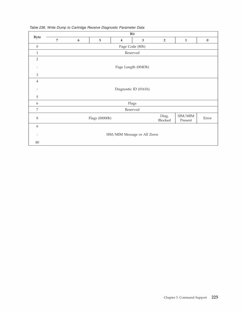
Table 236. Write Dump to Cartridge Receive Diagnostic Parameter Data
Byte
Bit
7 6 5 4 3 2 1 0
0 Page Code (80h)
1 Reserved
2
:
3
Page Length (004Dh)
4
:
5
Diagnostic ID (0161h)
6 Flags
7 Reserved
8 Flags (00000b)
Diag.
Blocked
SIM/MIM
Present
Error
9
:
80
SIM/MIM Message or All Zeros
Chapter 3. Command Support 225
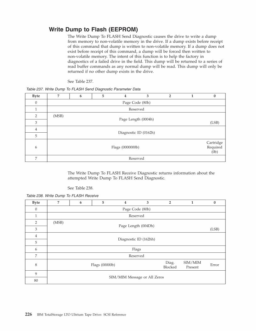
Write Dump to Flash (EEPROM)
The Write Dump To FLASH Send Diagnostic causes the drive to write a dump
from memory to non-volatile memory in the drive. If a dump exists before receipt
of this command that dump is written to non-volatile memory. If a dump does not
exist before receipt of this command, a dump will be forced then written to
non-volatile memory. The intent of this function is to help the factory in
diagnostics of a failed drive in the field. This dump will be returned to a series of
read buffer commands as any normal dump will be read. This dump will only be
returned if no other dump exists in the drive.
See Table 237.
Table 237. Write Dump To FLASH Send Diagnostic Parameter Data
Byte 7 6 5 4 3 2 1 0
0 Page Code (80h)
1 Reserved
2 (MSB)
Page Length (0004h)
3 (LSB)
4
Diagnostic ID (0162h)
5
6 Flags (0000000b)
Cartridge
Required
(0b)
7 Reserved
The Write Dump To FLASH Receive Diagnostic returns information about the
attempted Write Dump To FLASH Send Diagnostic.
See Table 238.
Table 238. Write Dump To FLASH Receive
Byte 7 6 5 4 3 2 1 0
0 Page Code (80h)
1 Reserved
2 (MSB)
Page Length (004Dh)
3 (LSB)
4
Diagnostic ID (162hh)
5
6 Flags
7 Reserved
8 Flags (00000b)
Diag.
Blocked
SIM/MIM
Present
Error
9
SIM/MIM Message or All Zeros
80
226 IBM TotalStorage LTO Ultrium Tape Drive: SCSI Reference
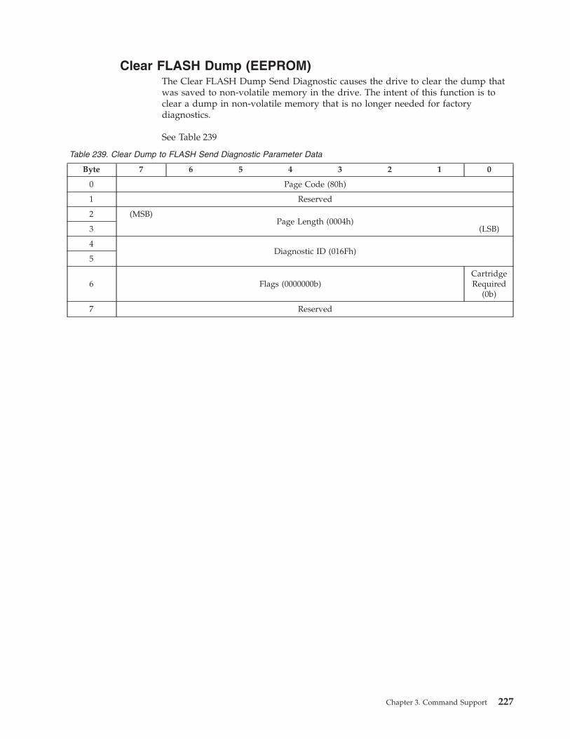
Clear FLASH Dump (EEPROM)
The Clear FLASH Dump Send Diagnostic causes the drive to clear the dump that
was saved to non-volatile memory in the drive. The intent of this function is to
clear a dump in non-volatile memory that is no longer needed for factory
diagnostics.
See Table 239
Table 239. Clear Dump to FLASH Send Diagnostic Parameter Data
Byte 7 6 5 4 3 2 1 0
0 Page Code (80h)
1 Reserved
2 (MSB)
Page Length (0004h)
3 (LSB)
4
Diagnostic ID (016Fh)
5
6 Flags (0000000b)
Cartridge
Required
(0b)
7 Reserved
Chapter 3. Command Support 227
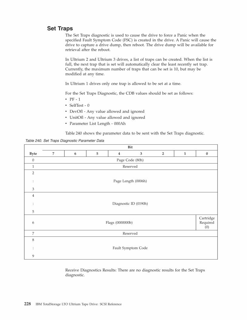
Set Traps
The Set Traps diagnostic is used to cause the drive to force a Panic when the
specified Fault Symptom Code (FSC) is created in the drive. A Panic will cause the
drive to capture a drive dump, then reboot. The drive dump will be available for
retrieval after the reboot.
In Ultrium 2 and Ultrium 3 drives, a list of traps can be created. When the list is
full, the next trap that is set will automatically clear the least recently set trap.
Currently, the maximum number of traps that can be set is 10, but may be
modified at any time.
In Ultrium 1 drives only one trap is allowed to be set at a time.
For the Set Traps Diagnostic, the CDB values should be set as follows:
v PF - 1
v SelfTest - 0
v DevOfl - Any value allowed and ignored
v UnitOfl - Any value allowed and ignored
v Parameter List Length - 000Ah
Table 240 shows the parameter data to be sent with the Set Traps diagnostic.
Table 240. Set Traps Diagnostic Parameter Data
Byte
Bit
7 6 5 4 3 2 1 0
0 Page Code (80h)
1 Reserved
2
:
3
Page Length (0006h)
4
:
5
Diagnostic ID (0190h)
6 Flags (0000000b)
Cartridge
Required
(0)
7 Reserved
8
:
9
Fault Symptom Code
Receive Diagnostics Results: There are no diagnostic results for the Set Traps
diagnostic.
228 IBM TotalStorage LTO Ultrium Tape Drive: SCSI Reference
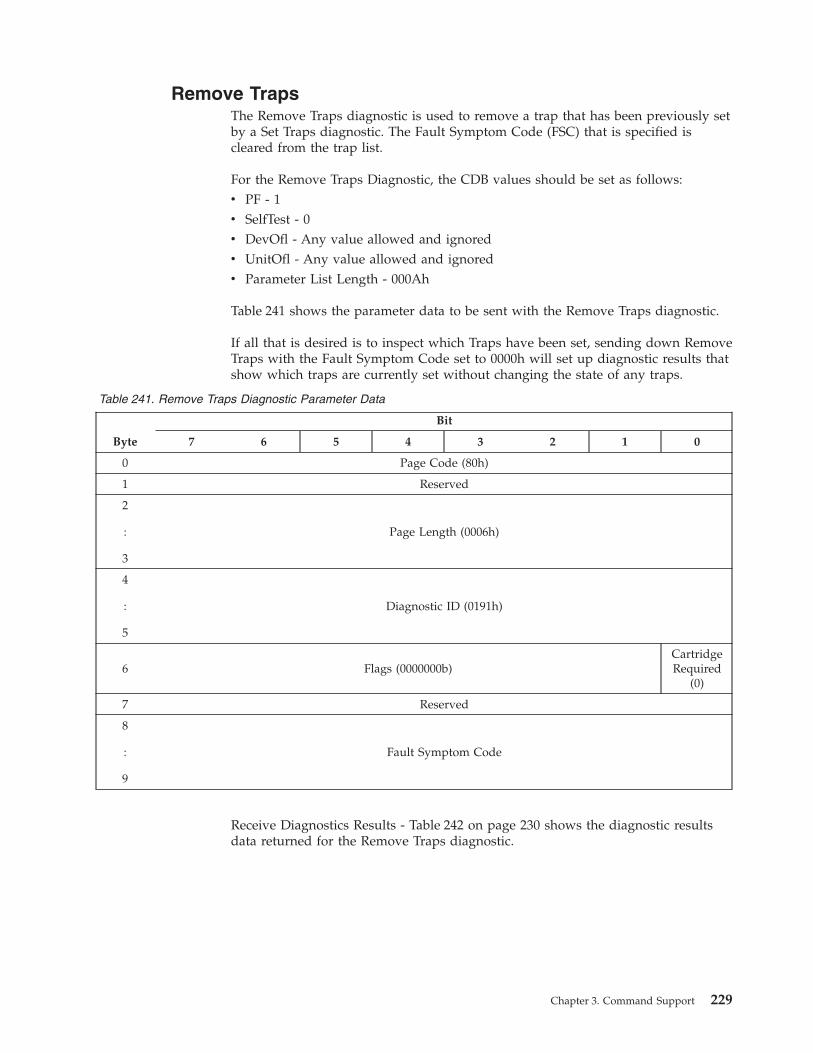
Remove Traps
The Remove Traps diagnostic is used to remove a trap that has been previously set
by a Set Traps diagnostic. The Fault Symptom Code (FSC) that is specified is
cleared from the trap list.
For the Remove Traps Diagnostic, the CDB values should be set as follows:
v PF - 1
v SelfTest - 0
v DevOfl - Any value allowed and ignored
v UnitOfl - Any value allowed and ignored
v Parameter List Length - 000Ah
Table 241 shows the parameter data to be sent with the Remove Traps diagnostic.
If all that is desired is to inspect which Traps have been set, sending down Remove
Traps with the Fault Symptom Code set to 0000h will set up diagnostic results that
show which traps are currently set without changing the state of any traps.
Table 241. Remove Traps Diagnostic Parameter Data
Byte
Bit
7 6 5 4 3 2 1 0
0 Page Code (80h)
1 Reserved
2
:
3
Page Length (0006h)
4
:
5
Diagnostic ID (0191h)
6 Flags (0000000b)
Cartridge
Required
(0)
7 Reserved
8
:
9
Fault Symptom Code
Receive Diagnostics Results - Table 242 on page 230 shows the diagnostic results
data returned for the Remove Traps diagnostic.
Chapter 3. Command Support 229
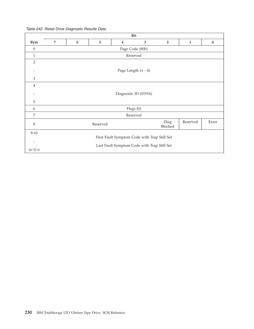
Table 242. Reset Drive Diagnostic Results Data
Byte
Bit
7 6 5 4 3 2 1 0
0 Page Code (80h)
1 Reserved
2
:
3
Page Length (n - 4)
4
:
5
Diagnostic ID (0191h)
6 Flags (0)
7 Reserved
8 Reserved
Diag
Blocked
Reserved Error
9-10
:
(n-1)-n
First Fault Symptom Code with Trap Still Set
Last Fault Symptom Code with Trap Still Set
230 IBM TotalStorage LTO Ultrium Tape Drive: SCSI Reference
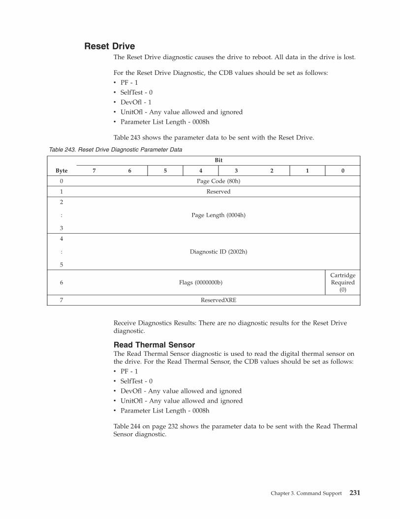
Reset Drive
The Reset Drive diagnostic causes the drive to reboot. All data in the drive is lost.
For the Reset Drive Diagnostic, the CDB values should be set as follows:
v PF - 1
v SelfTest - 0
v DevOfl - 1
v UnitOfl - Any value allowed and ignored
v Parameter List Length - 0008h
Table 243 shows the parameter data to be sent with the Reset Drive.
Table 243. Reset Drive Diagnostic Parameter Data
Byte
Bit
7 6 5 4 3 2 1 0
0 Page Code (80h)
1 Reserved
2
:
3
Page Length (0004h)
4
:
5
Diagnostic ID (2002h)
6 Flags (0000000b)
Cartridge
Required
(0)
7 ReservedXRE
Receive Diagnostics Results: There are no diagnostic results for the Reset Drive
diagnostic.
Read Thermal Sensor
The Read Thermal Sensor diagnostic is used to read the digital thermal sensor on
the drive. For the Read Thermal Sensor, the CDB values should be set as follows:
v PF - 1
v SelfTest - 0
v DevOfl - Any value allowed and ignored
v UnitOfl - Any value allowed and ignored
v Parameter List Length - 0008h
Table 244 on page 232 shows the parameter data to be sent with the Read Thermal
Sensor diagnostic.
Chapter 3. Command Support 231
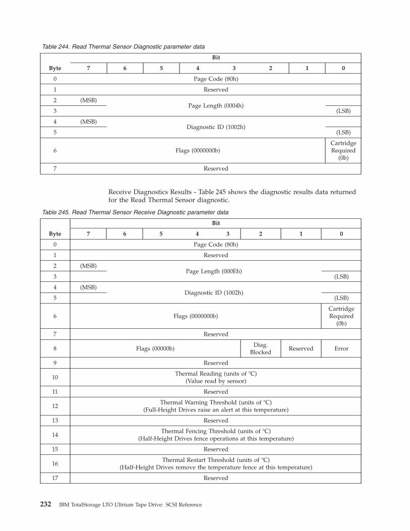
Table 244. Read Thermal Sensor Diagnostic parameter data
Byte
Bit
7 6 5 4 3 2 1 0
0 Page Code (80h)
1 Reserved
2 (MSB)
Page Length (0004h)
3 (LSB)
4 (MSB)
Diagnostic ID (1002h)
5 (LSB)
6 Flags (0000000b)
Cartridge
Required
(0b)
7 Reserved
Receive Diagnostics Results - Table 245 shows the diagnostic results data returned
for the Read Thermal Sensor diagnostic.
Table 245. Read Thermal Sensor Receive Diagnostic parameter data
Byte
Bit
7 6 5 4 3 2 1 0
0 Page Code (80h)
1 Reserved
2 (MSB)
Page Length (000Eh)
3 (LSB)
4 (MSB)
Diagnostic ID (1002h)
5 (LSB)
6 Flags (0000000b)
Cartridge
Required
(0b)
7 Reserved
8 Flags (00000b)
Diag.
Blocked
Reserved Error
9 Reserved
10
Thermal Reading (units of
oC)(Value read by sensor)
11 Reserved
12
Thermal Warning Threshold (units of
oC)(Full-Height Drives raise an alert at this temperature)
13 Reserved
14
Thermal Fencing Threshold (units of
oC)(Half-Height Drives fence operations at this temperature)
15 Reserved
16
Thermal Restart Threshold (units of
oC)(Half-Height Drives remove the temperature fence at this temperature)
17 Reserved
232 IBM TotalStorage LTO Ultrium Tape Drive: SCSI Reference
Table 245. Read Thermal Sensor Receive Diagnostic parameter data (continued)
Byte
Bit
7 6 5 4 3 2 1 0
Note: A value of 00h in any of the Thermal value fields indicates the value is not applicable.
Chapter 3. Command Support 233
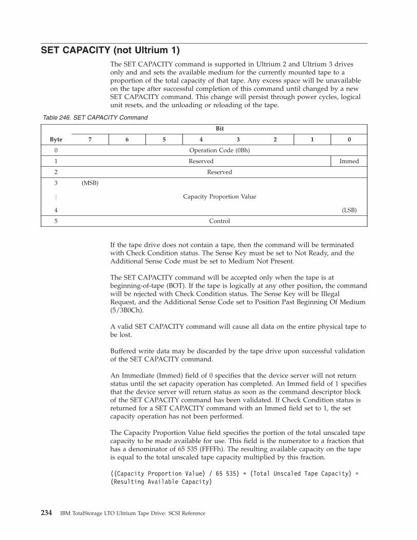
SET CAPACITY (not Ultrium 1)
The SET CAPACITY command is supported in Ultrium 2 and Ultrium 3 drives
only and and sets the available medium for the currently mounted tape to a
proportion of the total capacity of that tape. Any excess space will be unavailable
on the tape after successful completion of this command until changed by a new
SET CAPACITY command. This change will persist through power cycles, logical
unit resets, and the unloading or reloading of the tape.
Table 246. SET CAPACITY Command
Byte
Bit
7 6 5 4 3 2 1 0
0 Operation Code (0Bh)
1 Reserved Immed
2 Reserved
3
:
4
(MSB)
Capacity Proportion Value
(LSB)
5 Control
If the tape drive does not contain a tape, then the command will be terminated
with Check Condition status. The Sense Key must be set to Not Ready, and the
Additional Sense Code must be set to Medium Not Present.
The SET CAPACITY command will be accepted only when the tape is at
beginning-of-tape (BOT). If the tape is logically at any other position, the command
will be rejected with Check Condition status. The Sense Key will be Illegal
Request, and the Additional Sense Code set to Position Past Beginning Of Medium
(5/3B0Ch).
A valid SET CAPACITY command will cause all data on the entire physical tape to
be lost.
Buffered write data may be discarded by the tape drive upon successful validation
of the SET CAPACITY command.
An Immediate (Immed) field of 0 specifies that the device server will not return
status until the set capacity operation has completed. An Immed field of 1 specifies
that the device server will return status as soon as the command descriptor block
of the SET CAPACITY command has been validated. If Check Condition status is
returned for a SET CAPACITY command with an Immed field set to 1, the set
capacity operation has not been performed.
The Capacity Proportion Value field specifies the portion of the total unscaled tape
capacity to be made available for use. This field is the numerator to a fraction that
has a denominator of 65 535 (FFFFh). The resulting available capacity on the tape
is equal to the total unscaled tape capacity multiplied by this fraction.
((Capacity Proportion Value) / 65 535) * (Total Unscaled Tape Capacity) =
(Resulting Available Capacity)
234 IBM TotalStorage LTO Ultrium Tape Drive: SCSI Reference
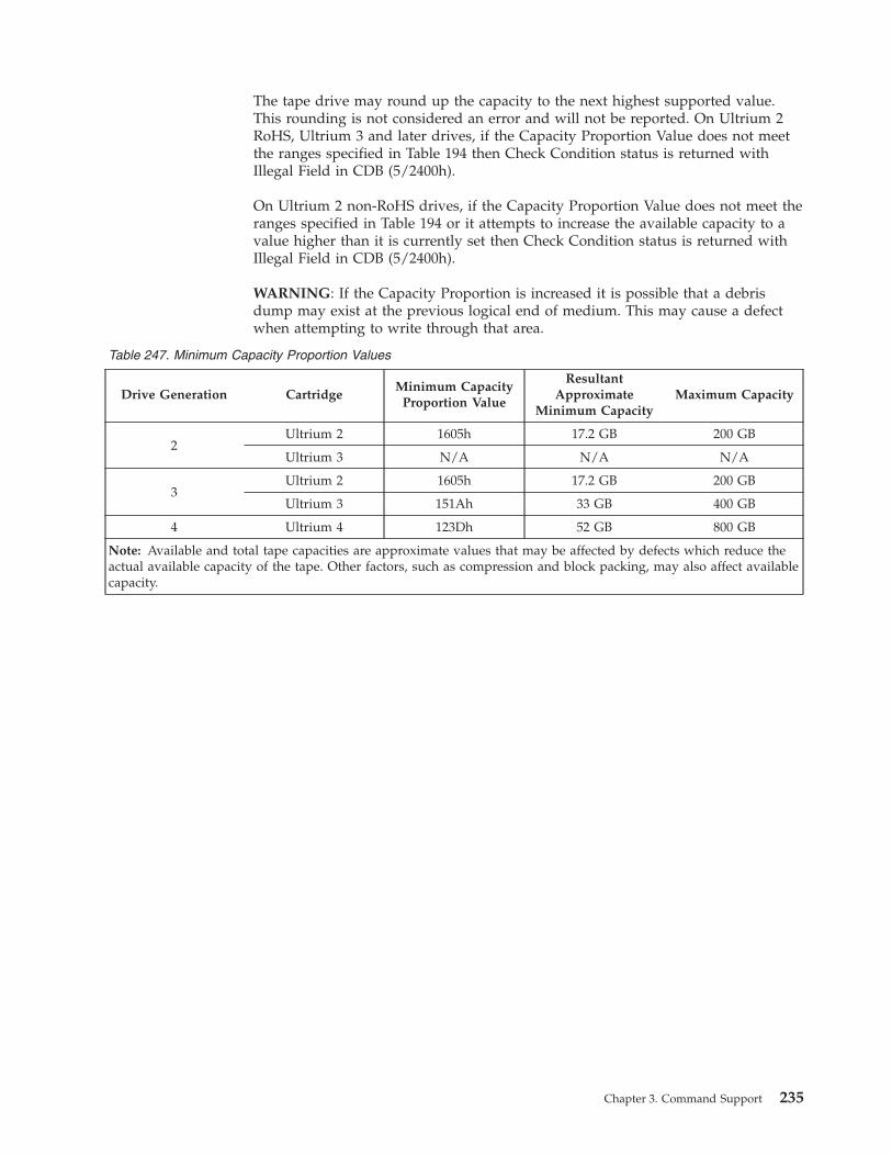
The tape drive may round up the capacity to the next highest supported value.
This rounding is not considered an error and will not be reported. On Ultrium 2
RoHS, Ultrium 3 and later drives, if the Capacity Proportion Value does not meet
the ranges specified in Table 194 then Check Condition status is returned with
Illegal Field in CDB (5/2400h).
On Ultrium 2 non-RoHS drives, if the Capacity Proportion Value does not meet the
ranges specified in Table 194 or it attempts to increase the available capacity to a
value higher than it is currently set then Check Condition status is returned with
Illegal Field in CDB (5/2400h).
WARNING: If the Capacity Proportion is increased it is possible that a debris
dump may exist at the previous logical end of medium. This may cause a defect
when attempting to write through that area.
Table 247. Minimum Capacity Proportion Values
Drive Generation Cartridge
Minimum Capacity
Proportion Value
Resultant
Approximate
Minimum Capacity
Maximum Capacity
2
Ultrium 2 1605h 17.2 GB 200 GB
Ultrium 3 N/A N/A N/A
3
Ultrium 2 1605h 17.2 GB 200 GB
Ultrium 3 151Ah 33 GB 400 GB
4 Ultrium 4 123Dh 52 GB 800 GB
Note: Available and total tape capacities are approximate values that may be affected by defects which reduce the
actual available capacity of the tape. Other factors, such as compression and block packing, may also affect available
capacity.
Chapter 3. Command Support 235
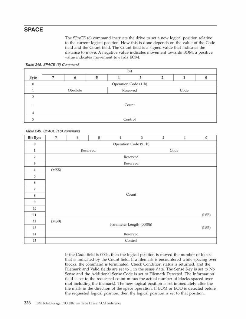
SPACE
The SPACE (6) command instructs the drive to set a new logical position relative
to the current logical position. How this is done depends on the value of the Code
field and the Count field. The Count field is a signed value that indicates the
distance to move. A negative value indicates movement towards BOM; a positive
value indicates movement towards EOM.
Table 248. SPACE (6) Command
Byte
Bit
7 6 5 4 3 2 1 0
0 Operation Code (11h)
1 Obsolete Reserved Code
2
:
4
Count
5 Control
Table 249. SPACE (16) command
Bit Byte 7 6 5 4 3 2 1 0
0 Operation Code (91 h)
1 Reserved Code
2 Reserved
3 Reserved
4 (MSB)
Count
5
6
7
8
9
10
11 (LSB)
12 (MSB)
Parameter Length (0000h)
13 (LSB)
14 Reserved
15 Control
If the Code field is 000b, then the logical position is moved the number of blocks
that is indicated by the Count field. If a filemark is encountered while spacing over
blocks, the command is terminated. Check Condition status is returned, and the
Filemark and Valid fields are set to 1 in the sense data. The Sense Key is set to No
Sense and the Additional Sense Code is set to Filemark Detected. The Information
field is set to the requested count minus the actual number of blocks spaced over
(not including the filemark). The new logical position is set immediately after the
file mark in the direction of the space operation. If BOM or EOD is detected before
the requested logical position, then the logical position is set to that position.
236 IBM TotalStorage LTO Ultrium Tape Drive: SCSI Reference
If the Code field is 001b, then the logical position is moved the number of file
marks indicated by the Count field. If BOM or EOD is detected before the
requested logical position, then the logical position is set to that position.
If end-of-data is encountered while spacing over blocks or filemarks, Check
Condition status is returned, the Sense Key is set to Blank Check, and the sense
data Valid field is set to 1 in the sense data. The Additional Sense Code is set to
End-Of-Data Detected. The sense data EOM field is set to 1 if end-of-data is
encountered at or after early-warning. The Information field is set to the requested
count minus the actual number of blocks or filemarks spaced over as defined by
the Code value. The medium is positioned such that a subsequent write operation
would append to the last record or filemark.
If the end-of-tape is encountered while spacing forward over blocks or filemarks,
Check Condition status is returned, and the Sense Key is set to Medium Error. The
Additional Sense Code is set to End-Of-Partition/Medium Detected, and the sense
data EOM and Valid fields are set to 1. The Information field is set to the requested
count minus the actual number of blocks or filemarks spaced over, as defined by
the Code value.
If beginning-of-tape is encountered while spacing over blocks or filemarks in the
reverse direction, the drive returns Check Condition status and sets the Sense Key
to No Sense. The Additional Sense Code is set to Beginning-Of-Partition/Medium
Detected. The sense data EOM and Valid fields are set to 1, and the Information
field is set to the total number of blocks or filemarks not spaced over (the
requested number of blocks or filemarks minus the actual number of blocks or
filemarks spaced over). A successfully completed SPACE command does not set
EOM to 1 at beginning-of-tape.
If the Code field is 011b, then the logical position is set to after the last valid block
on tape. In this case the Count field is ignored.
Any other value of the Code field causes Check Condition status to be returned.
Spacing to sequential file marks is not supported. Set marks are not supported. The
Sense Key is set to Illegal Request and the ASC/ASCQ is set to Invalid Field in
CDB (2400).
The explicit command set is not supported. The Parameter Length field of the
SPACE (16) command is set to 0. If the Parameter Length field is set to any other
value, the command is terminated with a Check Condition status. The sense key is
set to Illegal Request and the additional sense code is set to Invalid Field In Cdb
(5/2400h)
Chapter 3. Command Support 237
TEST UNIT READY
The TEST UNIT READY command reports when there is a medium in the drive
that is ready to accept medium access commands. If a medium is loaded and a
problem is detected that does not force the automatic ejection of the medium,
GOOD status will still be returned to the TEST UNIT READY command. Whatever
error is detected will be returned in response to the next medium access command.
Table 250. TEST UNIT READY Command
Byte
Bit
7 6 5 4 3 2 1 0
0 Operation Code (00h)
1 Obsolete Reserved
2 Reserved
3 Reserved
4 Reserved
5 Control
238 IBM TotalStorage LTO Ultrium Tape Drive: SCSI Reference
VERIFY
The VERIFY command causes data to be read from the tape and passed through
the drive’s error detection and correction hardware to determine whether it can be
recovered from the tape. The amount of data to be read is indicated by the
Verification Length field and the Fixed field in the same manner as is used in a
READ command. (See “READ” on page 147.)
Table 251. VERIFY Command
Byte
Bit
7 6 5 4 3 2 1 0
0 Operation Code (13h)
1 Obsolete Reserved Immed(0) BCmp(0) Fixed
2
:
4
Verification Length
5 Control
The VERIFY command is supported by all drives.
The Immed and BCmp fields are not supported and must be set to 0.
Chapter 3. Command Support 239

WRITE
The WRITE command causes data to be transferred to the drive in a Data Out and
written to tape.
Table 252. WRITE Command
Byte
Bit
7 6 5 4 3 2 1 0
0 Operation Code (0Ah)
1 Obsolete Reserved Fixed
2
:
4
Transfer Length
5 Control
If the Fixed field is set to 1, the Block Length (see “Mode Block Descriptor” on
page 109) is set to 0, and the Transfer Length field is not 0, Check Condition status
is returned with Illegal Field in CDB (5/2400h).
If the Fixed field is set to 0, the initiator transfers a single block of the length
indicated in Transfer Length.
If the Fixed field is set to 1, the initiator transfers a sequence of blocks. The
number of blocks is given by the Transfer Length field. The length of the blocks is
given by the current fixed block length (see “Mode Block Descriptor” on page 109).
If the current logical block number is greater than FFFFFF00h and less than
FFFFFFF0h, rules for Logical EOM processing are applied. If the current logical
block number is greater than or equal to FFFFFFF0h, rules for physical end of tape
processing are applied.
240 IBM TotalStorage LTO Ultrium Tape Drive: SCSI Reference
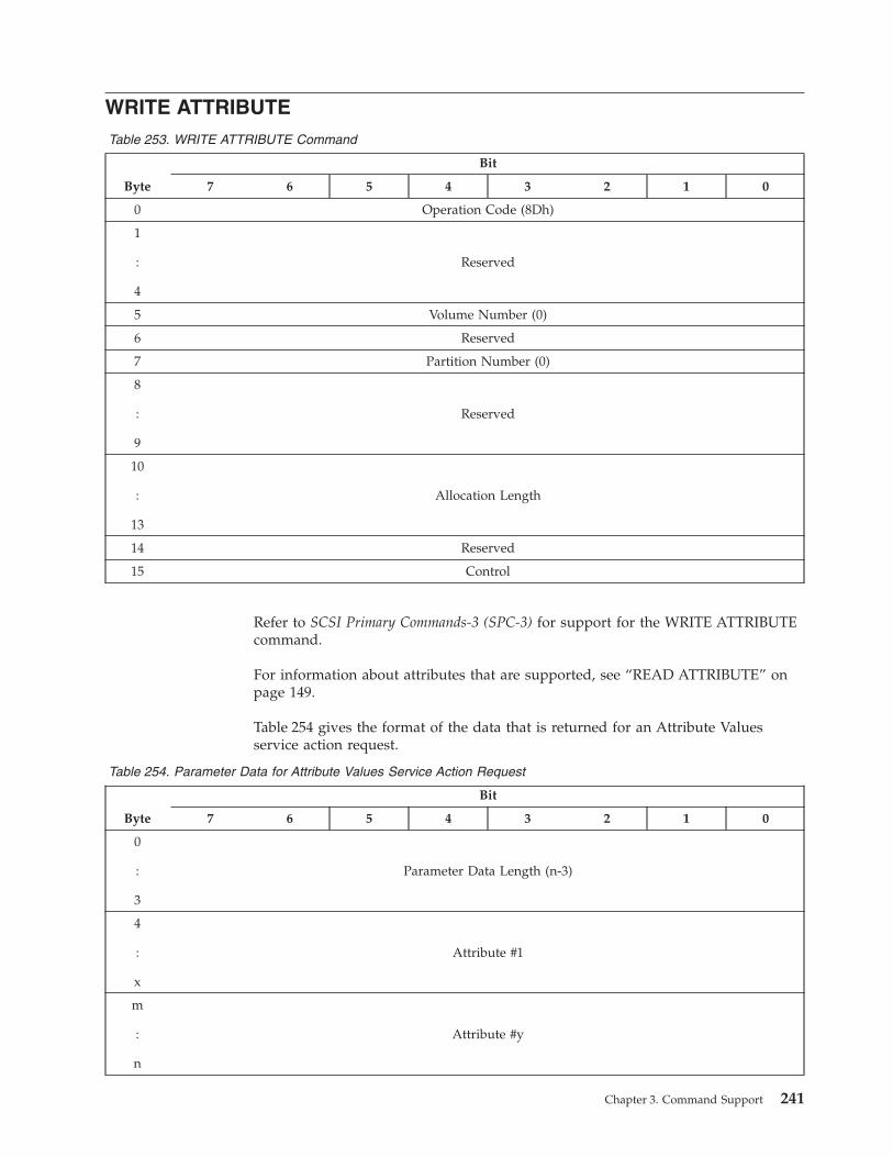
WRITE ATTRIBUTE
Table 253. WRITE ATTRIBUTE Command
Byte
Bit
7 6 5 4 3 2 1 0
0 Operation Code (8Dh)
1
:
4
Reserved
5 Volume Number (0)
6 Reserved
7 Partition Number (0)
8
:
9
Reserved
10
:
13
Allocation Length
14 Reserved
15 Control
Refer to SCSI Primary Commands-3 (SPC-3) for support for the WRITE ATTRIBUTE
command.
For information about attributes that are supported, see “READ ATTRIBUTE” on
page 149.
Table 254 gives the format of the data that is returned for an Attribute Values
service action request.
Table 254. Parameter Data for Attribute Values Service Action Request
Byte
Bit
7 6 5 4 3 2 1 0
0
:
3
Parameter Data Length (n-3)
4
:
x
Attribute #1
m
:
n
Attribute #y
Chapter 3. Command Support 241

WRITE BUFFER
The WRITE BUFFER command transfers data into the memory on the drive for the
purpose of diagnostics, tests, or firmware upgrade.
Table 255. WRITE BUFFER Command
Byte
Bit
7 6 5 4 3 2 1 0
0 Operation Code (3Bh)
1 Obsolete Mode
2 Buffer ID
3
:
5
Buffer Offset
6
:
8
Parameter List Length
9 Control
Values for the Mode field and their meaning are described in Table 256.
Table 256. Description of Mode Field
Mode Description Support
00h Write combined header and data 1, 2, 3, 4
02h Write data 1, 2, 3, 4
04h Download microcode 1, 2, 3, 4
05h Download microcode and save 1, 2, 3, 4
06h Download microcode with offsets 1, 2, 3, 4
07h Download microcode with offsets and save 1, 2, 3, 4
0Ah Echo buffer 2, 3, 4
Legend:
1 = supported in IBM TotalStorage LTO Ultrium Tape Drive (commonly called the Ultrium 1 tape drive)
2 = supported in IBM TotalStorage LTO Ultrium 2 Tape Drive (commonly called the Ultrium 2 tape drive)
3 = supported in IBM TotalStorage LTO Ultrium 3 Tape Drive (commonly called the Ultrium 3 tape drive)
4 = supported in IBM TotalStorage LTO Ultrium 4 Tape Drive (commonly called the Ultrium 4 tape drive)
If the Mode field is 00h, the data to be written is sent with a 4-byte header, which
must be set to all zeroes.
The Buffer ID field indicates which buffer is to be written.
To download firmware, Modes 04h, 05h, 06h, and 07h are accepted and handled in
the same fashion. Any Buffer ID value in these modes is allowed and ignored. The
code must be downloaded with strictly increasing offsets. If it is not, no data is
242 IBM TotalStorage LTO Ultrium Tape Drive: SCSI Reference
written and Check Condition status is generated. The Sense Key is set to Illegal
Request (5) and the ASC/ASCQ is set to Invalid Field in CDB (2400). Ending status
is given when the code has been successfully saved to flash, but before the drive
has initiated its reset.
If Mode is set to 0Ah, the data is stored in the echo buffer. The Buffer ID and
Buffer Offset fields are ignored in this mode.
The Buffer Offset field indicates where in the buffer the data should be written.
This must be smaller than the size of the buffer.
The Parameter List Length field holds the amount of data. This must be smaller
than the difference between the Buffer Offset field and the size of the buffer. If it is
not, no data is written and Check Condition status is generated. The Sense Key is
set to Illegal Request (5) and the ASC/ASCQ is set to Invalid Field in CDB (2400).
Buffers that may be written to are Test, Firmware, and VPD (see “READ BUFFER”
on page 166).
Chapter 3. Command Support 243
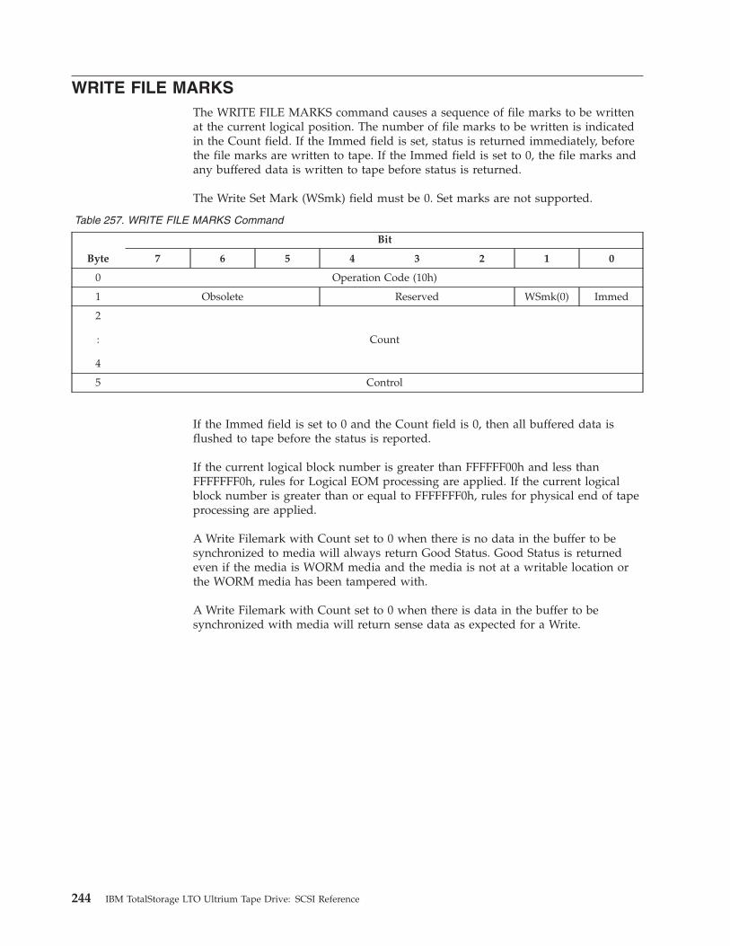
WRITE FILE MARKS
The WRITE FILE MARKS command causes a sequence of file marks to be written
at the current logical position. The number of file marks to be written is indicated
in the Count field. If the Immed field is set, status is returned immediately, before
the file marks are written to tape. If the Immed field is set to 0, the file marks and
any buffered data is written to tape before status is returned.
The Write Set Mark (WSmk) field must be 0. Set marks are not supported.
Table 257. WRITE FILE MARKS Command
Byte
Bit
7 6 5 4 3 2 1 0
0 Operation Code (10h)
1 Obsolete Reserved WSmk(0) Immed
2
:
4
Count
5 Control
If the Immed field is set to 0 and the Count field is 0, then all buffered data is
flushed to tape before the status is reported.
If the current logical block number is greater than FFFFFF00h and less than
FFFFFFF0h, rules for Logical EOM processing are applied. If the current logical
block number is greater than or equal to FFFFFFF0h, rules for physical end of tape
processing are applied.
A Write Filemark with Count set to 0 when there is no data in the buffer to be
synchronized to media will always return Good Status. Good Status is returned
even if the media is WORM media and the media is not at a writable location or
the WORM media has been tampered with.
A Write Filemark with Count set to 0 when there is data in the buffer to be
synchronized with media will return sense data as expected for a Write.
244 IBM TotalStorage LTO Ultrium Tape Drive: SCSI Reference
Chapter 4. Error Sense Information
Sense Data
For a description of Sense data, see “Sense Data Format” on page 187.
Sense Data Management
The drive maintains three types of Sense data:
Current Sense
The Sense data associated with the last command received from the
initiator.
Deferred Sense
The Sense data from a command that has been reported as Good, but has
generated sense data after being reported. This may be a command with
the Immediate flag set or may be a buffered write. A command with the
Immediate flag set generates sense for the server that sent the command. A
buffered write may generate sense for all servers.
Unit Attention Sense
The Sense data generated by a Unit Attention condition. (See “Unit
Attention Conditions” on page 245.) This is generated for all servers. When
a Unit Attention condition has been driven by a command (for example,
when mode parameters have changed), a Unit Attention is posted for all
initiators except the one that caused the change.
Commands generate Check Condition status if there is Deferred Sense data or Unit
Attention data available, depending on Table 8 on page 17. All commands generate
Check Condition status if the command itself generates sense data. If the next
command after the Check Condition status is not a REQUEST SENSE command,
then all sense data for that initiator is cleared.
When a REQUEST SENSE command is received, the Current Sense is returned. If
there is no Current Sense, the Deferred Sense is returned. If there is no Deferred
Sense, the Unit Attention Sense is returned. If there is no Unit Attention Sense,
default sense data is returned. Once a particular set of sense data has been
returned, that sense data is cleared. Any other sense data that is still pending may
still cause Check Condition status for subsequent commands.
Unit Attention Conditions
The drive generates a Unit Attention condition under the following circumstances:
v Reset condition (for example, power-on, SCSI reset, bus device reset)
v Tape Loaded condition (for example, media inserted, LOAD command from
another initiator)
v Mode parameters changed by another initiator
v Drive firmware has been upgraded
The drive only maintains one Unit Attention condition at any one time for any one
initiator. If a subsequent Unit Attention condition is generated, it replaces the
© Copyright IBM Corp. 2002, 2003, 2004, 2005, 2006, 2007 245

existing one if it is of higher priority. If it is of lower priority, it is ignored. The
priorities are in the order listed above, with a reset being highest priority and a
firmware upgrade being lowest priority.
Persistent Errors
When errors occur that prevent tape operation, they are reported persistently until
the problem is cleared. For medium-related errors (usually reported with a Sense
Key of 3), the error is reported until the cartridge is successfully unloaded. For
hardware-related errors (usually reported with a Sense Key of 4), the error is
reported until the drive successfully performs a power-on self test. These persistent
errors are only reported on those commands that are eligible for deferred Check
Condition reporting (see Table 4 on page 8). The error may or may not be reported
as Deferred.
Fencing Behavior
The Ultrium 2 and Ultrium 3 drives will fence the drive (prevent certain
operations) when errors are detected that could endanger customer data if further
usage is allowed. The operations that are prevented depend on the nature of the
error encountered and the current drive state. The drive will post an FSC for the
original error that caused the fence condition. Then, fencing FSCs will be reported
as status to the attempted host commands that are not allowed due to fence.
The following Fence states are defined and used:
1. ALLOW_NO_OPERATION
a. All medium access commands (Read/Write/Motion) are rejected.
b. (SCSI/Panel/LDI) Unload is accepted.
c. After the cartridge is ejected:
v When load is attempted, the cartridge stays at mount position and Good
status is returned for TUR.
v From the above state, the cartridge can be ejected normally.
v Other medium access commands are rejected.2. ALLOW_UNLOAD
a. All medium access commands (Read/Write/Motion) are rejected.
b. (SCSI/Panel/LDI) Unload is accepted.
c. Once a cartridge is ejected, Fence state is cleared. You can load a new
cartridge and perform all medium access commands.3. ALLOW_ALLOCATE
a. All medium access commands (Read/Write/Motion) are rejected.
b. (SCSI/Panel/LDI) Unload is accepted.
c. Once a cartridge is ejected, Fence state is cleared. You can load a new
cartridge and perform all medium access commands.
d. Space command is rejected while in Fence state.4. MID-TAPE RECOVERY
See the “Mode Page 2Fh: Behavior Configuration Mode Page” on page 131 for
a description of this behavior.
See Table 258 on page 247 for the errors that trigger the fence states.
246 IBM TotalStorage LTO Ultrium Tape Drive: SCSI Reference

Table 258. Fence State to Error Mapping
Description Fence State
ALLOW_NO_OPERATION
v Severe Drive Hardware problem
v Severe Media Hardware problem
v Temperature Overrange
v Load or Unload Hardware problem
v Severe Firmware Problem
ALLOW_LOCATE
v Hardware Problem detected that could affect Writing
v Hardware Problem detected that could affect Reading
ALLOW_UNLOAD
v Serious Drive Hardware problem — May be recovered
on a different mount
v Serious Media problem — Drive may be recovered on
different mount
v Serious Firmware problem — May be recovered on
different mount
MID-TAPE RECOVERY See “Mode Page 2Fh: Behavior Configuration Mode
Page” on page 131
Chapter 4. Error Sense Information 247

248 IBM TotalStorage LTO Ultrium Tape Drive: SCSI Reference
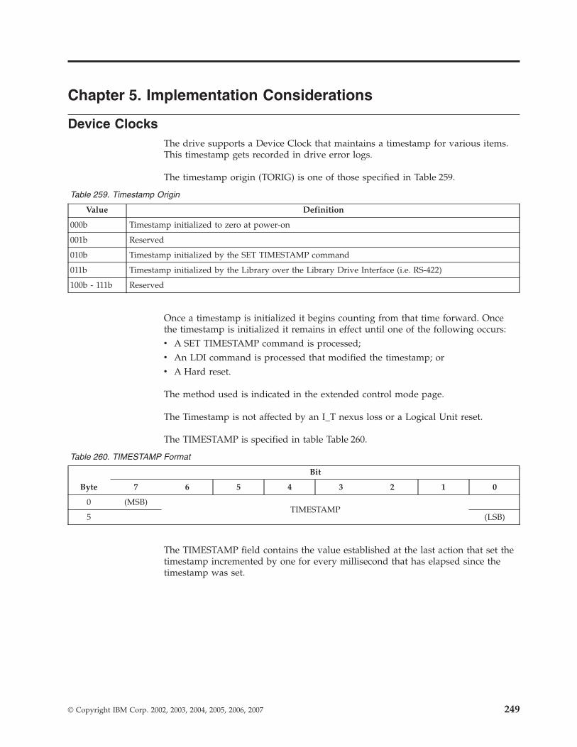
Chapter 5. Implementation Considerations
Device Clocks
The drive supports a Device Clock that maintains a timestamp for various items.
This timestamp gets recorded in drive error logs.
The timestamp origin (TORIG) is one of those specified in Table 259.
Table 259. Timestamp Origin
Value Definition
000b Timestamp initialized to zero at power-on
001b Reserved
010b Timestamp initialized by the SET TIMESTAMP command
011b Timestamp initialized by the Library over the Library Drive Interface (i.e. RS-422)
100b - 111b Reserved
Once a timestamp is initialized it begins counting from that time forward. Once
the timestamp is initialized it remains in effect until one of the following occurs:
v A SET TIMESTAMP command is processed;
v An LDI command is processed that modified the timestamp; or
v A Hard reset.
The method used is indicated in the extended control mode page.
The Timestamp is not affected by an I_T nexus loss or a Logical Unit reset.
The TIMESTAMP is specified in table Table 260.
Table 260. TIMESTAMP Format
Byte
Bit
7 6 5 4 3 2 1 0
0 (MSB)
TIMESTAMP
5 (LSB)
The TIMESTAMP field contains the value established at the last action that set the
timestamp incremented by one for every millisecond that has elapsed since the
timestamp was set.
© Copyright IBM Corp. 2002, 2003, 2004, 2005, 2006, 2007 249

250 IBM TotalStorage LTO Ultrium Tape Drive: SCSI Reference

Chapter 6. WORM BEHAVIORS
Conditions for Writing
If the following condition is met, writing is allowed:
v the cartridge is uninitialized
If all the following conditions are met, writing is allowed:
v the current logical position is at BOT
v there are only filemarks between here and EOD
If all of the following conditions are met, writing is allowed:
v if the current logical position is at BOT
v there are exactly 1 or 2 data records, followed by 0 to infinite number of
filemarks, followed by no data records, followed by EOD
If all of the following conditions are met, writing is allowed:
v the current logical position is BETWEEN BOT and EOD:
v there are only filemarks from the current logical position to EOD
v there is at least one filemark immediately before the current logical position
If the following condition is met, writing is allowed:
v the current logical position is AT® EOD
Command Behavior When WORM Medium Has Been Tampered With
Table 261 specifies the behavior of the drive when it has detected the WORM
medium that is loaded in the drive has been tampered with (See Sequential Access
Drive Configuration page).
Table 261. Behavior when the loaded medium has suspect integrity
Command WTRE=01b WTRE=00b or 10b
Write 0x7/300D 0x7/300D
Write Filemark n (n !=0) 0x7/300D 0x7/300D
Write Filemark 0 (buffered data) 0x7/300D 0x7/300D
Write Filemark 0 (no buffered data) Good Good
Erase 0x7/300D 0x7/300D
Read Good 0x3/300D
Verify Good 0x3/300D
Space Good 0x3/300D
Locate to (block !=0) Good 0x3/300D
Locate to 0 Good Good
Rewind Good Good
Unload Good Good
Load Good Good
© Copyright IBM Corp. 2002, 2003, 2004, 2005, 2006, 2007 251

252 IBM TotalStorage LTO Ultrium Tape Drive: SCSI Reference
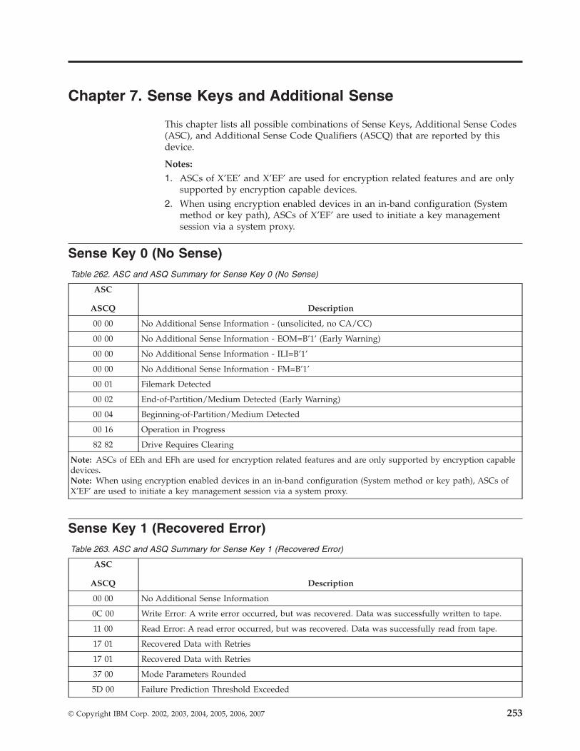
Chapter 7. Sense Keys and Additional Sense
This chapter lists all possible combinations of Sense Keys, Additional Sense Codes
(ASC), and Additional Sense Code Qualifiers (ASCQ) that are reported by this
device.
Notes:
1. ASCs of X’EE’ and X’EF’ are used for encryption related features and are only
supported by encryption capable devices.
2. When using encryption enabled devices in an in-band configuration (System
method or key path), ASCs of X’EF’ are used to initiate a key management
session via a system proxy.
Sense Key 0 (No Sense)
Table 262. ASC and ASQ Summary for Sense Key 0 (No Sense)
ASC
ASCQ Description
00 00 No Additional Sense Information - (unsolicited, no CA/CC)
00 00 No Additional Sense Information - EOM=B’1’ (Early Warning)
00 00 No Additional Sense Information - ILI=B’1’
00 00 No Additional Sense Information - FM=B’1’
00 01 Filemark Detected
00 02 End-of-Partition/Medium Detected (Early Warning)
00 04 Beginning-of-Partition/Medium Detected
00 16 Operation in Progress
82 82 Drive Requires Clearing
Note: ASCs of EEh and EFh are used for encryption related features and are only supported by encryption capable
devices.
Note: When using encryption enabled devices in an in-band configuration (System method or key path), ASCs of
X’EF’ are used to initiate a key management session via a system proxy.
Sense Key 1 (Recovered Error)
Table 263. ASC and ASQ Summary for Sense Key 1 (Recovered Error)
ASC
ASCQ Description
00 00 No Additional Sense Information
0C 00 Write Error: A write error occurred, but was recovered. Data was successfully written to tape.
11 00 Read Error: A read error occurred, but was recovered. Data was successfully read from tape.
17 01 Recovered Data with Retries
17 01 Recovered Data with Retries
37 00 Mode Parameters Rounded
5D 00 Failure Prediction Threshold Exceeded
© Copyright IBM Corp. 2002, 2003, 2004, 2005, 2006, 2007 253
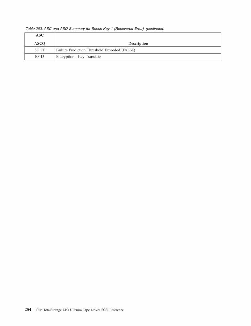
Table 263. ASC and ASQ Summary for Sense Key 1 (Recovered Error) (continued)
ASC
ASCQ Description
5D FF Failure Prediction Threshold Exceeded (FALSE)
EF 13 Encryption - Key Translate
254 IBM TotalStorage LTO Ultrium Tape Drive: SCSI Reference
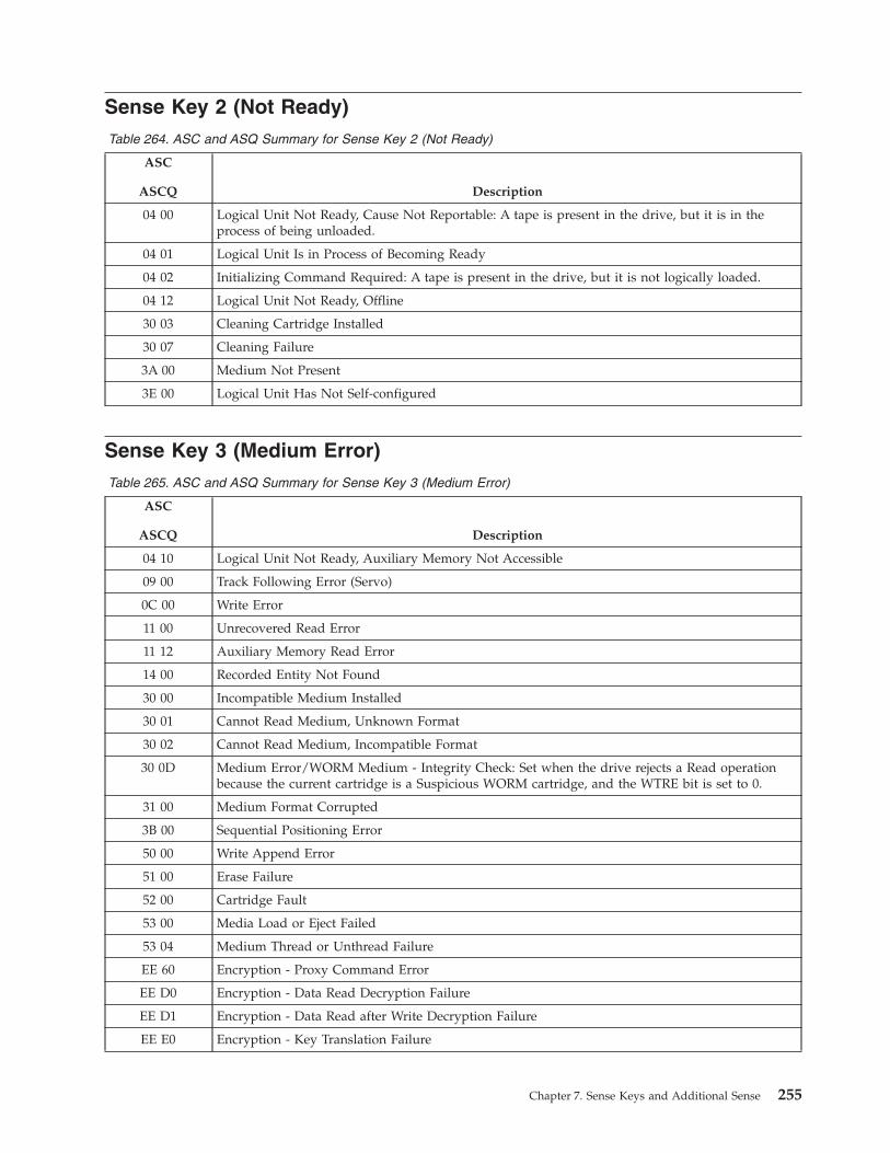
Sense Key 2 (Not Ready)
Table 264. ASC and ASQ Summary for Sense Key 2 (Not Ready)
ASC
ASCQ Description
04 00 Logical Unit Not Ready, Cause Not Reportable: A tape is present in the drive, but it is in the
process of being unloaded.
04 01 Logical Unit Is in Process of Becoming Ready
04 02 Initializing Command Required: A tape is present in the drive, but it is not logically loaded.
04 12 Logical Unit Not Ready, Offline
30 03 Cleaning Cartridge Installed
30 07 Cleaning Failure
3A 00 Medium Not Present
3E 00 Logical Unit Has Not Self-configured
Sense Key 3 (Medium Error)
Table 265. ASC and ASQ Summary for Sense Key 3 (Medium Error)
ASC
ASCQ Description
04 10 Logical Unit Not Ready, Auxiliary Memory Not Accessible
09 00 Track Following Error (Servo)
0C 00 Write Error
11 00 Unrecovered Read Error
11 12 Auxiliary Memory Read Error
14 00 Recorded Entity Not Found
30 00 Incompatible Medium Installed
30 01 Cannot Read Medium, Unknown Format
30 02 Cannot Read Medium, Incompatible Format
30 0D Medium Error/WORM Medium - Integrity Check: Set when the drive rejects a Read operation
because the current cartridge is a Suspicious WORM cartridge, and the WTRE bit is set to 0.
31 00 Medium Format Corrupted
3B 00 Sequential Positioning Error
50 00 Write Append Error
51 00 Erase Failure
52 00 Cartridge Fault
53 00 Media Load or Eject Failed
53 04 Medium Thread or Unthread Failure
EE 60 Encryption - Proxy Command Error
EE D0 Encryption - Data Read Decryption Failure
EE D1 Encryption - Data Read after Write Decryption Failure
EE E0 Encryption - Key Translation Failure
Chapter 7. Sense Keys and Additional Sense 255
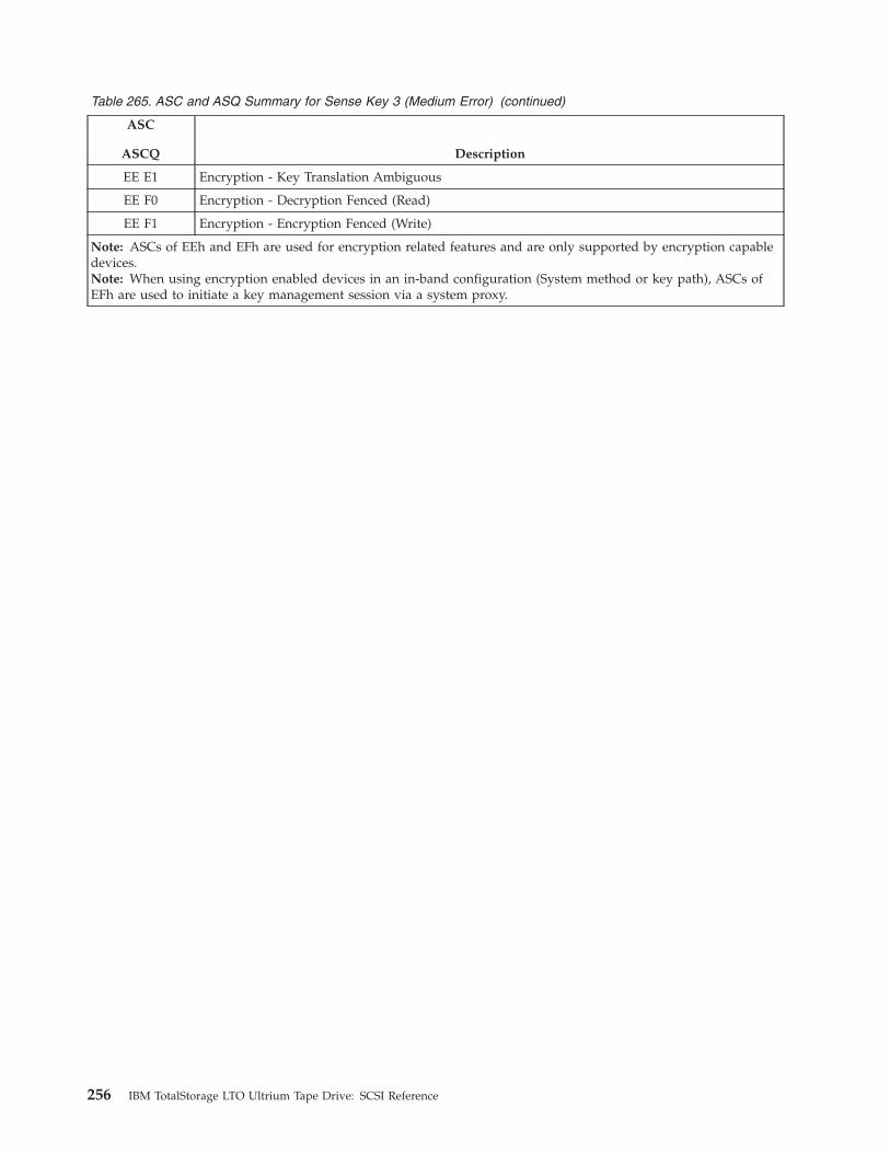
Table 265. ASC and ASQ Summary for Sense Key 3 (Medium Error) (continued)
ASC
ASCQ Description
EE E1 Encryption - Key Translation Ambiguous
EE F0 Encryption - Decryption Fenced (Read)
EE F1 Encryption - Encryption Fenced (Write)
Note: ASCs of EEh and EFh are used for encryption related features and are only supported by encryption capable
devices.
Note: When using encryption enabled devices in an in-band configuration (System method or key path), ASCs of
EFh are used to initiate a key management session via a system proxy.
256 IBM TotalStorage LTO Ultrium Tape Drive: SCSI Reference
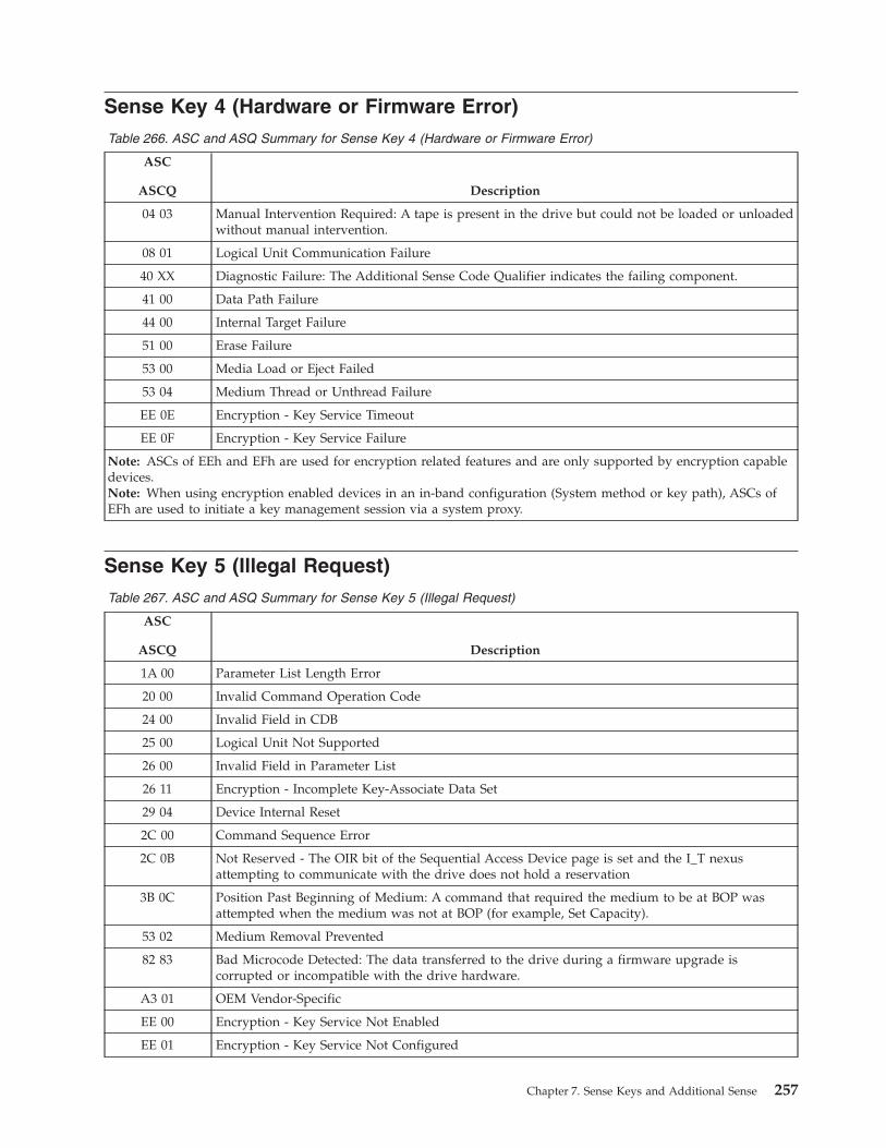
Sense Key 4 (Hardware or Firmware Error)
Table 266. ASC and ASQ Summary for Sense Key 4 (Hardware or Firmware Error)
ASC
ASCQ Description
04 03 Manual Intervention Required: A tape is present in the drive but could not be loaded or unloaded
without manual intervention.
08 01 Logical Unit Communication Failure
40 XX Diagnostic Failure: The Additional Sense Code Qualifier indicates the failing component.
41 00 Data Path Failure
44 00 Internal Target Failure
51 00 Erase Failure
53 00 Media Load or Eject Failed
53 04 Medium Thread or Unthread Failure
EE 0E Encryption - Key Service Timeout
EE 0F Encryption - Key Service Failure
Note: ASCs of EEh and EFh are used for encryption related features and are only supported by encryption capable
devices.
Note: When using encryption enabled devices in an in-band configuration (System method or key path), ASCs of
EFh are used to initiate a key management session via a system proxy.
Sense Key 5 (Illegal Request)
Table 267. ASC and ASQ Summary for Sense Key 5 (Illegal Request)
ASC
ASCQ Description
1A 00 Parameter List Length Error
20 00 Invalid Command Operation Code
24 00 Invalid Field in CDB
25 00 Logical Unit Not Supported
26 00 Invalid Field in Parameter List
26 11 Encryption - Incomplete Key-Associate Data Set
29 04 Device Internal Reset
2C 00 Command Sequence Error
2C 0B Not Reserved - The OIR bit of the Sequential Access Device page is set and the I_T nexus
attempting to communicate with the drive does not hold a reservation
3B 0C Position Past Beginning of Medium: A command that required the medium to be at BOP was
attempted when the medium was not at BOP (for example, Set Capacity).
53 02 Medium Removal Prevented
82 83 Bad Microcode Detected: The data transferred to the drive during a firmware upgrade is
corrupted or incompatible with the drive hardware.
A3 01 OEM Vendor-Specific
EE 00 Encryption - Key Service Not Enabled
EE 01 Encryption - Key Service Not Configured
Chapter 7. Sense Keys and Additional Sense 257
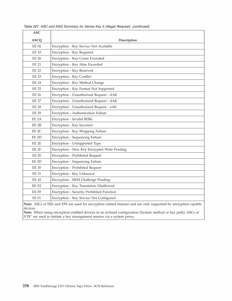
Table 267. ASC and ASQ Summary for Sense Key 5 (Illegal Request) (continued)
ASC
ASCQ Description
EE 02 Encryption - Key Service Not Available
EE 10 Encryption - Key Required
EE 20 Encryption - Key Count Exceeded
EE 21 Encryption - Key Alias Exceeded
EE 22 Encryption - Key Reserved
EE 23 Encryption - Key Conflict
EE 24 Encryption - Key Method Change
EE 25 Encryption - Key Format Not Supported
EE 26 Encryption - Unauthorized Request - dAK
EE 27 Encryption - Unauthorized Request - dAK
EE 28 Encryption - Unauthorized Request - eAK
EE 29 Encryption - Authentication Failure
EE 2A Encryption - Invalid RDKi
EE 2B Encryption - Key Incorrect
EE 2C Encryption - Key Wrapping Failure
EE 2D Encryption - Sequencing Failure
EE 2E Encryption - Unsupported Type
EE 2F Encryption - New Key Encrypted Write Pending
EE 30 Encryption - Prohibited Request
EE 2D Encryption - Sequencing Failure
EE 30 Encryption - Prohibited Request
EE 31 Encryption - Key Unknown
EE 42 Encryption - EKM Challenge Pending
EE E2 Encryption - Key Translation Disallowed
EE FF Encryption - Security Prohibited Function
EF 01 Encryption - Key Service Not Configured
Note: ASCs of EEh and EFh are used for encryption related features and are only supported by encryption capable
devices.
Note: When using encryption enabled devices in an in-band configuration (System method or key path), ASCs of
X’EF’ are used to initiate a key management session via a system proxy.
258 IBM TotalStorage LTO Ultrium Tape Drive: SCSI Reference
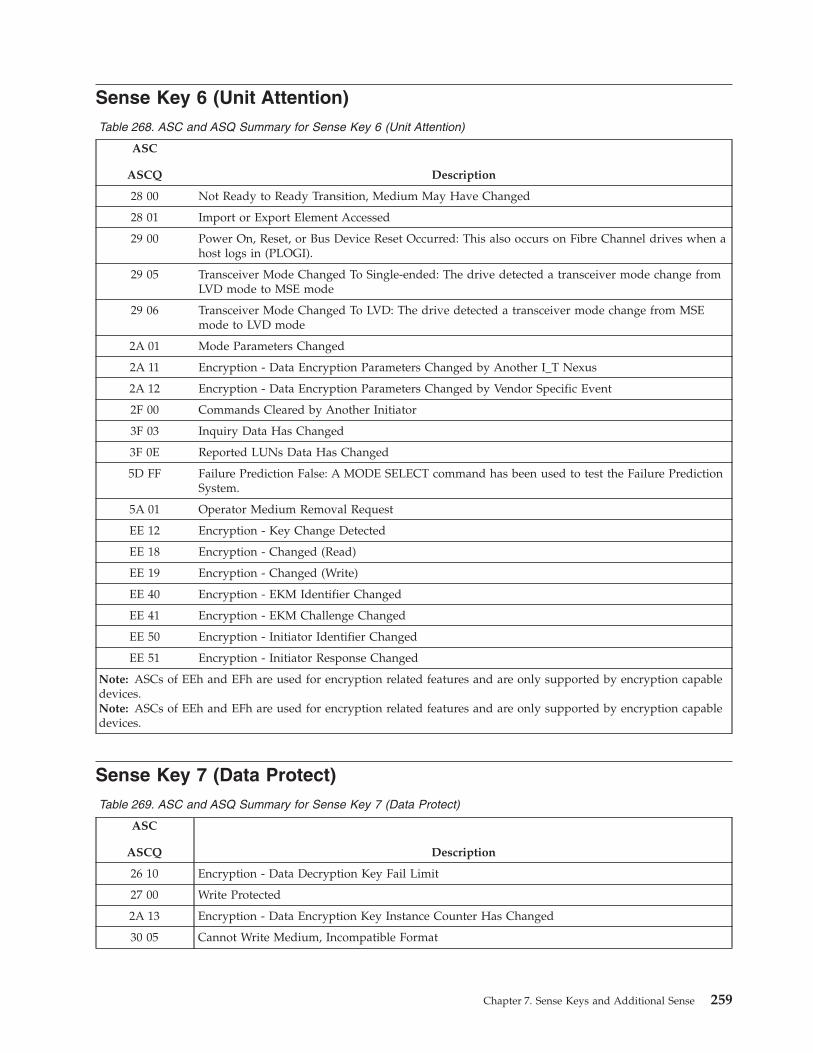
Sense Key 6 (Unit Attention)
Table 268. ASC and ASQ Summary for Sense Key 6 (Unit Attention)
ASC
ASCQ Description
28 00 Not Ready to Ready Transition, Medium May Have Changed
28 01 Import or Export Element Accessed
29 00 Power On, Reset, or Bus Device Reset Occurred: This also occurs on Fibre Channel drives when a
host logs in (PLOGI).
29 05 Transceiver Mode Changed To Single-ended: The drive detected a transceiver mode change from
LVD mode to MSE mode
29 06 Transceiver Mode Changed To LVD: The drive detected a transceiver mode change from MSE
mode to LVD mode
2A 01 Mode Parameters Changed
2A 11 Encryption - Data Encryption Parameters Changed by Another I_T Nexus
2A 12 Encryption - Data Encryption Parameters Changed by Vendor Specific Event
2F 00 Commands Cleared by Another Initiator
3F 03 Inquiry Data Has Changed
3F 0E Reported LUNs Data Has Changed
5D FF Failure Prediction False: A MODE SELECT command has been used to test the Failure Prediction
System.
5A 01 Operator Medium Removal Request
EE 12 Encryption - Key Change Detected
EE 18 Encryption - Changed (Read)
EE 19 Encryption - Changed (Write)
EE 40 Encryption - EKM Identifier Changed
EE 41 Encryption - EKM Challenge Changed
EE 50 Encryption - Initiator Identifier Changed
EE 51 Encryption - Initiator Response Changed
Note: ASCs of EEh and EFh are used for encryption related features and are only supported by encryption capable
devices.
Note: ASCs of EEh and EFh are used for encryption related features and are only supported by encryption capable
devices.
Sense Key 7 (Data Protect)
Table 269. ASC and ASQ Summary for Sense Key 7 (Data Protect)
ASC
ASCQ Description
26 10 Encryption - Data Decryption Key Fail Limit
27 00 Write Protected
2A 13 Encryption - Data Encryption Key Instance Counter Has Changed
30 05 Cannot Write Medium, Incompatible Format
Chapter 7. Sense Keys and Additional Sense 259

Table 269. ASC and ASQ Summary for Sense Key 7 (Data Protect) (continued)
ASC
ASCQ Description
30 0D Data Protect/WORM Medium - Integrity Check: Set when the drive rejects a Write operation
because the current cartridge is a Suspicious WORM cartridge.
30 0C Data Protect/WORM Medium - Overwrite Attempted: Set when the drive rejects a Write
operation because the rules for allowing WORM writes have not been met.
52 00 Cartridge Fault
74 00 Security Error
74 01 Encryption - Unable to Decrypt Data
74 02 Encryption - Unencrypted Data Encountered While Decrypting
74 03 Encryption - Incorrect Data Encryption Key
74 04 Encryption - Cryptographic Integrity Validation Failed
74 05 Encryption - Error Decrypting Data
EF 10 Encryption - Key Required
EF 11 Encryption - Key Generation
EF 13 Encryption - Key Translate
EF 1A Encryption - Key Optional
EF C0 Encryption - No Operation
Note: ASCs of EEh and EFh are used for encryption related features and are only supported by encryption capable
devices.
Note: ASCs of EEh and EFh are used for encryption related features and are only supported by encryption capable
devices.
Sense Key 8 (Blank Check)
Table 270. ASC and ASQ Summary for Sense Key 8 (Blank Check)
ASC
ASCQ Description
00 05 End-of-Data (EOD) Detected
0B 01 The drive detected an overtemperature condition. The currently loaded medium has been ejected.
14 03 End-of-Data (EOD) not Found
260 IBM TotalStorage LTO Ultrium Tape Drive: SCSI Reference
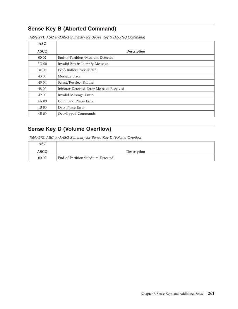
Sense Key B (Aborted Command)
Table 271. ASC and ASQ Summary for Sense Key B (Aborted Command)
ASC
ASCQ Description
00 02 End-of-Partition/Medium Detected
3D 00 Invalid Bits in Identify Message
3F 0F Echo Buffer Overwritten
43 00 Message Error
45 00 Select/Reselect Failure
48 00 Initiator Detected Error Message Received
49 00 Invalid Message Error
4A 00 Command Phase Error
4B 00 Data Phase Error
4E 00 Overlapped Commands
Sense Key D (Volume Overflow)
Table 272. ASC and ASQ Summary for Sense Key D (Volume Overflow)
ASC
ASCQ Description
00 02 End-of-Partition/Medium Detected
Chapter 7. Sense Keys and Additional Sense 261

262 IBM TotalStorage LTO Ultrium Tape Drive: SCSI Reference
Chapter 8. Device Hardware Encryption (Ultrium 4)
Ultrium 4 devices contain hardware which performs user data write encryption
and read decryption, protecting all user data written to the medium from
unauthorized use [provided it is integrated into a secure system design].
© Copyright IBM Corp. 2002, 2003, 2004, 2005, 2006, 2007 263

264 IBM TotalStorage LTO Ultrium Tape Drive: SCSI Reference
Chapter 9. Attachment Features
Types of Interface Attachments
The Ultrium Tape Drive communicates with servers that use SCSI parallel, Fibre
Channel, or SAS interfaces. The interfaces share certain tape LUN behaviors, but
also possess unique features. This chapter describes the common and unique
features of these interfaces.
Common Tape LUN Behaviors
Parallel SCSI and Fibre Channel and SAS interfaces share the following tape LUN
behaviors:
v Power-on procedure
v Reset strategy
v Abort handling
v Multi-initiator support
v Status codes
The sections that follow describe each behavior.
Power-On
The drive responds to INQUIRY, REPORT LUNs, REQUEST SENSE, and TEST
UNIT READY commands within 5 seconds of power-on. The first command (other
than INQUIRY or REQUEST SENSE) from any initiator gets a Check Condition
status with Unit Attention sense data for the power-on. After this, any medium
access command is reported with a Sense Key of Not Ready and an ASC/ASCQ of
LUN Has Not Self-Configured Yet (3E00). Once the drive has completed its self test
and setup procedures, the drive attempts to load any tape that is present. Medium
access commands are reported with an ASC/ASCQ of Drive in Process of
Becoming Ready (0401).
Reset Strategy
The drive supports the hard reset option as is required by SCSI-3. On receiving a
reset, the following actions are taken:
v The current I/O process is aborted, as in “Abort Handling” on page 266.
v Any queued I/O processes from other initiators are removed.
v All reservations are cleared.
v All mode values are reset to their defaults.
v Synchronous/Wide negotiations are cleared (applies only to SCSI parallel
attach).
v A unit attention condition is set.
v A logical position is established that may or may not be the same as the position
prior to the reset. Where possible, the logical position prior to reset is
maintained.
For drives that use he Fibre Channel or SAS interface, the next command that is
eligible for the Unit Attention Check Condition from each initiator gets a Check
© Copyright IBM Corp. 2002, 2003, 2004, 2005, 2006, 2007 265
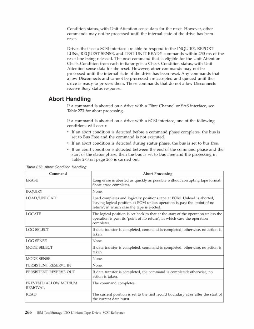
Condition status, with Unit Attention sense data for the reset. However, other
commands may not be processed until the internal state of the drive has been
reset.
Drives that use a SCSI interface are able to respond to the INQUIRY, REPORT
LUNs, REQUEST SENSE, and TEST UNIT READY commands within 250 ms of the
reset line being released. The next command that is eligible for the Unit Attention
Check Condition from each initiator gets a Check Condition status, with Unit
Attention sense data for the reset. However, other commands may not be
processed until the internal state of the drive has been reset. Any commands that
allow Disconnects and cannot be processed are accepted and queued until the
drive is ready to process them. Those commands that do not allow Disconnects
receive Busy status response.
Abort Handling
If a command is aborted on a drive with a Fibre Channel or SAS interface, see
Table 273 for abort processing.
If a command is aborted on a drive with a SCSI interface, one of the following
conditions will occur:
v If an abort condition is detected before a command phase completes, the bus is
set to Bus Free and the command is not executed.
v If an abort condition is detected during status phase, the bus is set to bus free.
v If an abort condition is detected between the end of the command phase and the
start of the status phase, then the bus is set to Bus Free and the processing in
Table 273 on page 266 is carried out.
Table 273. Abort Condition Handling
Command Abort Processing
ERASE Long erase is aborted as quickly as possible without corrupting tape format.
Short erase completes.
INQUIRY None.
LOAD/UNLOAD Load completes and logically positions tape at BOM. Unload is aborted,
leaving logical position at BOM unless operation is past the ‘point of no
return’, in which case the tape is ejected.
LOCATE The logical position is set back to that at the start of the operation unless the
operation is past its ‘point of no return’, in which case the operation
completes.
LOG SELECT If data transfer is completed, command is completed; otherwise, no action is
taken.
LOG SENSE None.
MODE SELECT If data transfer is completed, command is completed; otherwise, no action is
taken.
MODE SENSE None.
PERSISTENT RESERVE IN None.
PERSISTENT RESERVE OUT If data transfer is completed, the command is completed; otherwise, no
action is taken.
PREVENT/ALLOW MEDIUM
REMOVAL
The command completes.
READ The current position is set to the first record boundary at or after the start of
the current data burst.
266 IBM TotalStorage LTO Ultrium Tape Drive: SCSI Reference
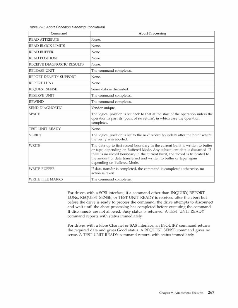
Table 273. Abort Condition Handling (continued)
Command Abort Processing
READ ATTRIBUTE None.
READ BLOCK LIMITS None.
READ BUFFER None.
READ POSITION None.
RECEIVE DIAGNOSTIC RESULTS None.
RELEASE UNIT The command completes.
REPORT DENSITY SUPPORT None.
REPORT LUNs None.
REQUEST SENSE Sense data is discarded.
RESERVE UNIT The command completes.
REWIND The command completes.
SEND DIAGNOSTIC Vendor unique.
SPACE The logical position is set back to that at the start of the operation unless the
operation is past its ‘point of no return’, in which case the operation
completes.
TEST UNIT READY None.
VERIFY The logical position is set to the next record boundary after the point where
the verify was aborted.
WRITE The data up to first record boundary in the current burst is written to buffer
or tape, depending on Buffered Mode. Any subsequent data is discarded. If
there is no record boundary in the current burst, the record is truncated to
the amount of data transferred and written to buffer or tape, again
depending on Buffered Mode.
WRITE BUFFER If data transfer is completed, the command is completed; otherwise, no
action is taken.
WRITE FILE MARKS The command completes.
For drives with a SCSI interface, if a command other than INQUIRY, REPORT
LUNs, REQUEST SENSE, or TEST UNIT READY is received after the abort but
before the drive is ready to process the command, the drive attempts to disconnect
and wait until the abort processing has completed before executing the command.
If disconnects are not allowed, Busy status is returned. A TEST UNIT READY
command reports with status immediately.
For drives with a Fibre Channel or SAS interface, an INQUIRY command returns
the required data and gives Good status. A REQUEST SENSE command gives no
sense. A TEST UNIT READY command reports with status immediately.
Chapter 9. Attachment Features 267

Multi-initiator Support
SCSI-attached drives support a maximum of two initiators on the same bus.
Fibre-Channel-attached drives and Serial Attached SCSI drives support an infinite
number of initiators, but have a limit on how many initiators can be logged in
processing commands concurrently. When this limit is exceeded, the least recently
used (LRU) initiator that is not reserved or does not have an outstanding
command will be implicitly logged out.
The drive supports untagged queuing when operating with multiple initiators. If a
command from one initiator is being processed when a command other than
INQUIRY, REPORT LUNs, REQUEST SENSE, and TEST UNIT READY is received
from a second initiator, the new command is queued. Media access commands (for
example, Write, Write Filemarks, Read, Verify, Rewind, Mode Select that changes
block size) are always executed in strict order of receipt. For drives with a SCSI
interface, if the queue is full or disconnect privilege is not granted in the new
command, the drive reports busy status.
The INQUIRY, REPORT LUNs, REQUEST SENSE, and TEST UNIT READY
commands are always processed immediately, irrespective of whether a command
from another initiator is being processed.
The drive maintains sense data for the supported number of initiators. On
Fibre-Channel-attached drives and Serial Attached SCSI drives, if an additional
initiator connects to the drive and causes an initiator to be implicitly logged out,
the drive erases all sense data for that initiator before processing the command for
the new initiator. See “Sense Data Management” on page 245 for more details of
sense data management.
Features of the Serial Attached SCSI (SAS) Interface
The World Wide Node Name and Port Name that are used by an Ultrium Tape
Drive follow the format of the Institute of Electrical and Electronics Engineers
(IEEE).
The IBM Ultrium Tape Drive is compliant with the American National Standard,
Project T10/1601-D, Information technology - Serial Attached SCSI - 1.1 (SAS-1.1),
Revision 10, 21 September 2005.
Status Codes
Table 274. Status Codes
Status Code Value Circumstance
Good 00h The command completed without problems.
Check Condition 02h A problem occurred during command execution. The sense data should be
examined to determine the nature of the problem.
Busy 08h The drive is unable to accept the command at this time. This status is
returned during the power-on sequence or if there are commands from too
many initiators outstanding. (See “Multi-initiator Support” on page 268.) It
is also returned when commands are issued without Disconnect Privilege
and when another command is in progress.
Reservation Conflict 18h This status is returned if the drive is reserved for an initiator other than
the one sending the command.
Queue Full 28h Not normally returned.
268 IBM TotalStorage LTO Ultrium Tape Drive: SCSI Reference
Features of the SCSI Interface
The Ultrium Tape Drive’s SCSI parallel interface features the following:
v LUN identification
v Bus parity errors
v Disconnect strategy
v Messages
LUN Identification
Identify messages are used to identify the LUN to which an initiator is connecting
and to identify which LUN is reconnecting to an initiator. These are required. The
LUN field in SCSI-2 commands is not used.
SPI Information Unit (Ultra 320 Attached drives only)
The following TASK MANAGEMENT FUNCTIONs are supported in SPI
Command Information Unit:
01h - ABORT TASK (see “Abort Handling” on page 266)
02h - ABORT TASK SET (see “Abort Handling” on page 266)
04h - CLEAR TASK SET (see “Abort Handling” on page 266)
08h - LOGICAL UNIT RESET (see “Abort Handling” on page 266)
20h - TARGET RESET (see “Abort Handling” on page 266)
The following TASK ATTRIBUTE CODEs are supported in SPI Command
Information Unit:
20h - SIMPLE
Bus Parity Errors (when using Data group transfers)
On detecting a bus parity error during a Command or Data Out phase or receiving
an Initiator Detected Error message during a Data In or Status phase, the drive
attempts to retry the Bus phase. A Restore Pointers message is sent to the initiator
and the transfer is repeated. Only one retry is attempted for any given burst. If the
retry fails or the Restore Pointers message is rejected by an Initiator Detected Error,
Message Reject, or Message Parity message, then the drive goes to the Status phase
and attempts to report Check Condition status. If this fails with an Initiator
Detected Error message, the drive goes to Bus Free. The Sense Key is set to
Aborted Command and the ASC/ASCQ is set to Command Phase Error (4A00) (if
the error was in the Command phase) or to Data Phase Error (4B00) (if the error
was in the Data phase). If the error was in the Status phase, the sense data remains
as that from the command.
If an Initiator Detected Error or Message Parity Error message is received during
the Message In phase, the initiator has detected an error in the message. The drive
goes to Message In and resends the message that was in error. If the subsequent
message is rejected with an Initiator Detected Error, then the drive goes to the
Status phase and sends Check Condition status. The Sense Key is set to Aborted
Command and the ASC/ASCQ is set to Initiator Detected Error (4800). If the
subsequent message is rejected with a Message Parity Error, then the drive goes to
the Status phase and sends Check Condition status. The Sense Key is set to
Aborted Command and the ASC/ASCQ is set to Message Error (4300).
Chapter 9. Attachment Features 269
On detecting a bus parity error during a Message Out phase, the drive handshakes
in all message bytes until ATN is deserted. It then stays in the Message Out phase
to indicate to the initiator that the whole Message Out phase should be resent.
Bus Parity Errors (when using Information unit transfers)
On detecting an iuCRC error in a SPI L_Q information unit, the drive goes bus
free. If the retry fails, then the drive goes to the SPI Status information unit and
attempts to report Check Condition status. If this fails with an Initiator Detected
Error message, the drive goes Bus Free. The Sense Key is set to Aborted Command
and the ASC/ASCQ is set to INFORMATION UNIT iuCRC ERROR DETECTED
error (4703h) (if the error was in the SPI Command information unit, SPI Data
information unit or Data Stream information unit). If the error was in the Status
information unit, the sense data from the command remains.
Disconnect Strategy
The disconnect strategy used by the drive is based on the assumption of
maximizing bus utilization for large sequential data transfers from a large data
buffer. The drive disconnects whenever it believes that it can provide better bus
utilization. This may be between Command and Data phases, between bursts of
data, or before sending status. However, the drive guarantees that it sends the
configured maximum burst size or the remaining data in the transfer in any single
Data phase burst if the maximum burst size has been set to a value other than 0.
270 IBM TotalStorage LTO Ultrium Tape Drive: SCSI Reference
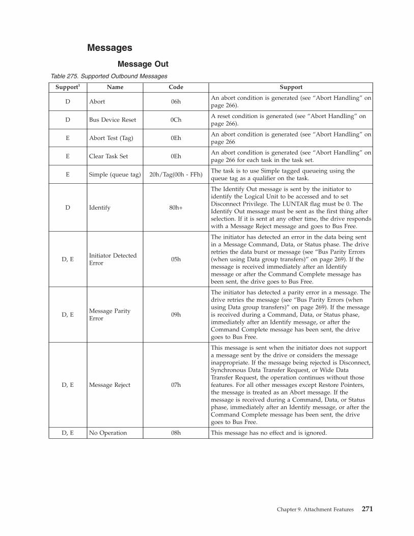
Messages
Message Out
Table 275. Supported Outbound Messages
Support1 Name Code Support
D Abort 06h
An abort condition is generated (see “Abort Handling” on
page 266).
D Bus Device Reset 0Ch
A reset condition is generated (see “Abort Handling” on
page 266).
E Abort Test (Tag) 0Eh
An abort condition is generated (see “Abort Handling” on
page 266
E Clear Task Set 0Eh
An abort condition is generated (see “Abort Handling” on
page 266 for each task in the task set.
E Simple (queue tag) 20h/Tag(00h - FFh)
The task is to use Simple tagged queueing using the
queue tag as a qualifier on the task.
D Identify 80h+
The Identify Out message is sent by the initiator to
identify the Logical Unit to be accessed and to set
Disconnect Privilege. The LUNTAR flag must be 0. The
Identify Out message must be sent as the first thing after
selection. If it is sent at any other time, the drive responds
with a Message Reject message and goes to Bus Free.
D, E
Initiator Detected
Error
05h
The initiator has detected an error in the data being sent
in a Message Command, Data, or Status phase. The drive
retries the data burst or message (see “Bus Parity Errors
(when using Data group transfers)” on page 269). If the
message is received immediately after an Identify
message or after the Command Complete message has
been sent, the drive goes to Bus Free.
D, E
Message Parity
Error
09h
The initiator has detected a parity error in a message. The
drive retries the message (see “Bus Parity Errors (when
using Data group transfers)” on page 269). If the message
is received during a Command, Data, or Status phase,
immediately after an Identify message, or after the
Command Complete message has been sent, the drive
goes to Bus Free.
D, E Message Reject 07h
This message is sent when the initiator does not support
a message sent by the drive or considers the message
inappropriate. If the message being rejected is Disconnect,
Synchronous Data Transfer Request, or Wide Data
Transfer Request, the operation continues without those
features. For all other messages except Restore Pointers,
the message is treated as an Abort message. If the
message is received during a Command, Data, or Status
phase, immediately after an Identify message, or after the
Command Complete message has been sent, the drive
goes to Bus Free.
D, E No Operation 08h This message has no effect and is ignored.
Chapter 9. Attachment Features 271
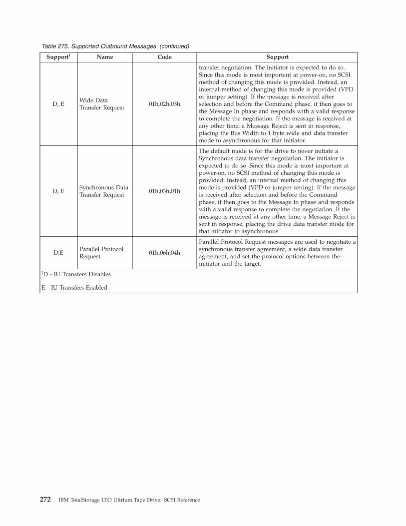
Table 275. Supported Outbound Messages (continued)
Support1 Name Code Support
D, E
Wide Data
Transfer Request
01h,02h,03h
transfer negotiation. The initiator is expected to do so.
Since this mode is most important at power-on, no SCSI
method of changing this mode is provided. Instead, an
internal method of changing this mode is provided (VPD
or jumper setting). If the message is received after
selection and before the Command phase, it then goes to
the Message In phase and responds with a valid response
to complete the negotiation. If the message is received at
any other time, a Message Reject is sent in response,
placing the Bus Width to 1 byte wide and data transfer
mode to asynchronous for that initiator.
D, E
Synchronous Data
Transfer Request
01h,03h,01h
The default mode is for the drive to never initiate a
Synchronous data transfer negotiation. The initiator is
expected to do so. Since this mode is most important at
power-on, no SCSI method of changing this mode is
provided. Instead, an internal method of changing this
mode is provided (VPD or jumper setting). If the message
is received after selection and before the Command
phase, it then goes to the Message In phase and responds
with a valid response to complete the negotiation. If the
message is received at any other time, a Message Reject is
sent in response, placing the drive data transfer mode for
that initiator to asynchronous
D,E
Parallel Protocol
Request
01h,06h,04h
Parallel Protocol Request messages are used to negotiate a
synchronous transfer agreement, a wide data transfer
agreement, and set the protocol options between the
initiator and the target.
1D - IU Transfers Disables
E - IU Transfers Enabled
272 IBM TotalStorage LTO Ultrium Tape Drive: SCSI Reference
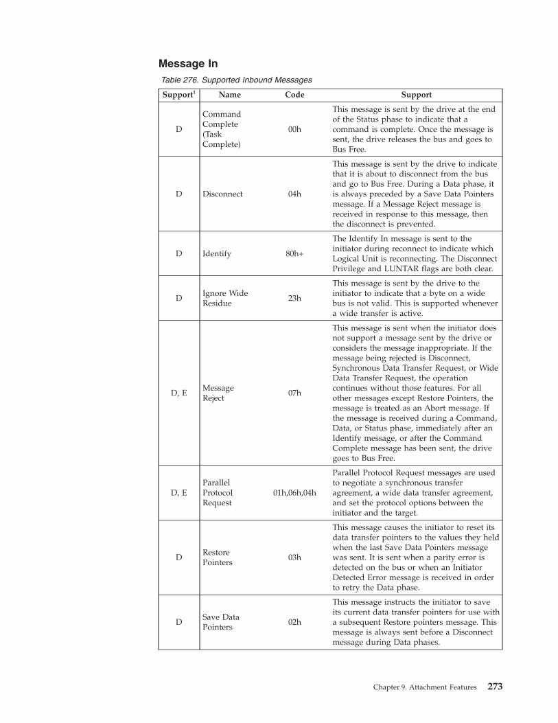
Message In
Table 276. Supported Inbound Messages
Support1 Name Code Support
D
Command
Complete
(Task
Complete)
00h
This message is sent by the drive at the end
of the Status phase to indicate that a
command is complete. Once the message is
sent, the drive releases the bus and goes to
Bus Free.
D Disconnect 04h
This message is sent by the drive to indicate
that it is about to disconnect from the bus
and go to Bus Free. During a Data phase, it
is always preceded by a Save Data Pointers
message. If a Message Reject message is
received in response to this message, then
the disconnect is prevented.
D Identify 80h+
The Identify In message is sent to the
initiator during reconnect to indicate which
Logical Unit is reconnecting. The Disconnect
Privilege and LUNTAR flags are both clear.
D
Ignore Wide
Residue
23h
This message is sent by the drive to the
initiator to indicate that a byte on a wide
bus is not valid. This is supported whenever
a wide transfer is active.
D, E
Message
Reject
07h
This message is sent when the initiator does
not support a message sent by the drive or
considers the message inappropriate. If the
message being rejected is Disconnect,
Synchronous Data Transfer Request, or Wide
Data Transfer Request, the operation
continues without those features. For all
other messages except Restore Pointers, the
message is treated as an Abort message. If
the message is received during a Command,
Data, or Status phase, immediately after an
Identify message, or after the Command
Complete message has been sent, the drive
goes to Bus Free.
D, E
Parallel
Protocol
Request
01h,06h,04h
Parallel Protocol Request messages are used
to negotiate a synchronous transfer
agreement, a wide data transfer agreement,
and set the protocol options between the
initiator and the target.
D
Restore
Pointers
03h
This message causes the initiator to reset its
data transfer pointers to the values they held
when the last Save Data Pointers message
was sent. It is sent when a parity error is
detected on the bus or when an Initiator
Detected Error message is received in order
to retry the Data phase.
D
Save Data
Pointers
02h
This message instructs the initiator to save
its current data transfer pointers for use with
a subsequent Restore pointers message. This
message is always sent before a Disconnect
message during Data phases.
Chapter 9. Attachment Features 273

Table 276. Supported Inbound Messages (continued)
Support1 Name Code Support
D, E
Synchronous
Data Transfer
Request
01h,03h,01h
The default mode is for the drive to never
initiate a Synchronous data transfer
negotiation. The initiator is expected to do
so. Since this mode is most important at
power-on, no SCSI method of changing this
mode is provided. Instead, an internal
method of changing this mode is provided
(VPD or jumper setting). If the message is
received after selection and before the
Command phase, it then goes to the
Message In phase and responds with a valid
response to complete the negotiation. If the
message is received at any other time, a
Message Reject is sent in response, placing
the drive data transfer mode for that
initiator to asynchronous
D, E
Wide Data
Transfer
Request
01h,02h,03h
The default mode is for the drive to never
initiate a Wide data transfer negotiation. The
initiator is expected to do so. Since this
mode is most important at power-on, no
SCSI method of changing this mode is
provided. Instead, an internal method of
changing this mode is provided (VPD or
jumper setting). If the message is received
after selection and before the Command
phase, it then goes to the Message In phase
and responds with a valid response to
complete the negotiation. If the message is
received at any other time, a Message Reject
is sent in response, placing the Bus Width to
1 byte wide and data transfer mode to
asynchronous for that initiator.
1D - IU Transfers Disables
E - IU Transfers Enabled
274 IBM TotalStorage LTO Ultrium Tape Drive: SCSI Reference
Features of the Fibre Channel Interface
The Ultrium Internal Tape Drive Model T200F (the Fibre Channel Generation 1
drive) is an Arbitrated-Loop-only device (also known as an NL port). The drive
supports Fibre Channel Arbitrated Loop (FC-AL) protocol, and uses Class 3 Service
frames. The drive also supports both public (switch-attached) and private loops.
Like the Ultrium Internal Tape Drive, the Ultrium 2 Tape Drive Model T400F (the
Fibre Channel Generation 2 drive) and the IBM TotalStorage Ultrium 3 Tape Drive
Model T800F (the Fibre Channel Generation 3 drive) can attach as an FC-AL device
(that is, L-Port). The drives also support operating as a public (switch-attached) or
private device (that is, L-Port to FL-Port; or L-Port to L-Port). The Ultrium 2 and
Ultrium 3 drives can also attach using the point-to-point protocol (also known as
an N-Port). When operating in the point-to-point protocol, the Ultrium 2 and
Ultrium 3 drives can attach in a Fabric topology (that is, N-Port to F-Port).
The World Wide Node Name and Port Name that are used by an Ultrium Tape
Drive follow the format of the Institute of Electrical and Electronics Engineers
(IEEE).
The IBM Ultrium Tape Drive is compliant with the FC-Tape Technical Report of the
Accredited Standard Committee NCITS. IBM recommends that your server’s device
driver and host bus adapter (HBA) use the Class 3 Error Recovery procedures that
are specified in the Fibre Channel Protocol for SCSI, Second Version (FCP-2).
Chapter 9. Attachment Features 275

276 IBM TotalStorage LTO Ultrium Tape Drive: SCSI Reference

Chapter 10. Firmware Download
This chapter describes Firmware download.
Identifying Level Hardware of Drive (Not Ultrium 1)
The firmware that is loaded in the drive will report a Load ID and RU Name in
Inquiry page 03h. The Load ID and RU Name are used to designate the Level
Hardware. The following table defines the Load ID and RU Name values for each
Level Hardware.
Table 277. Load ID and RU Name Designation
Product (Level
Hardware) Load ID
RU Name (EBCDIC
string) (Hex
representation)
F/W
(Min
Level)
Product ID
(Left-Aligned)
(IBM)
Product ID (Left-Aligned)
(OEM)
Ultrium 2 Ultra
160
A1700299
″AJEFGP99″
0xC1D1C5C6C7D7F9F9
-
ULT3580-TD2 ULTRIUM-TD2
Ultrium 2 FC 2G A170029A
″AJEFGP9A″
0xC1D1C5C6C7D7F9C1
-
Ultrium 2 Ultra
160 RoHS
A1700D67
″AJEFAX67″
0xC1D1C5C6C1E7F6F7
-
Ultrium 2 FC 2G
RoHS
A1700D68
″AJEFAX68″
0xC1D1C5C6C1E7F6F8
-
Ultrium 3
Ultrium 3 Ultra
160
A1700D50
″AJEFAX50″
0xC1D1C5C6C1E7F5F0
-
ULT3580-TD3 ULTRIUM-TD3
Ultrium 3 Ultra
160 RoHS
5BG2
Ultrium 3 FC2
A1700D52
″AJEFAX52″
0xC1D1C5C6C1E7F5F2
-
Ultrium 3 FC4
RoHS
5BG2
Ultrium 3
Half-High SAS
A1700D64 ″AJEFAX64″
0xC1D1C5C6C1E7F6F4
- ULT3580-HH3 ULTRIUM-HH3
A1700D53 ″AJEFAX53″
0xC1D1C5C6C1E7F5F3
Ultrium 3
Half-High Ultra
160
A1700D63 AJEFAX69
A1700D69 ″AJEFAX69″
0xC1D1C5C6C1E7F6F9
Ultrium 4
Ultrium 4 U160 A1700D6A ″AJEFAX6A″
0xC1D1C5C6C1E7F6C1
- ULT3580-TD4 ULTRIUM-TD4
Ultirum 4 FC4 A1700D6B ″AJEFAX6B″
0xC1D1C5C6C1E7F6C2
Ultrium 4 SAS A1700D6C ″AJEFAX6C″
0xC1D1C5C6C1E7F6C3
Ultrium 4 U320 A1700D70 ″AJEFAX70″
0xC1D1C5C6C1E7F7F0
© Copyright IBM Corp. 2002, 2003, 2004, 2005, 2006, 2007 277

Table 277. Load ID and RU Name Designation (continued)
Product (Level
Hardware) Load ID
RU Name (EBCDIC
string) (Hex
representation)
F/W
(Min
Level)
Product ID
(Left-Aligned)
(IBM)
Product ID (Left-Aligned)
(OEM)
- Not Applicable
278 IBM TotalStorage LTO Ultrium Tape Drive: SCSI Reference
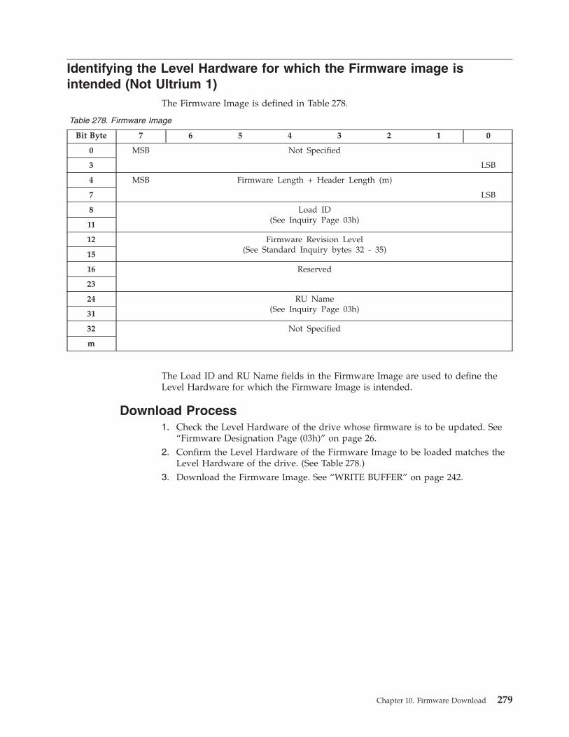
Identifying the Level Hardware for which the Firmware image is
intended (Not Ultrium 1)
The Firmware Image is defined in Table 278.
Table 278. Firmware Image
Bit Byte 7 6 5 4 3 2 1 0
0 MSB Not Specified
3 LSB
4 MSB Firmware Length + Header Length (m)
7 LSB
8 Load ID
(See Inquiry Page 03h) 11
12 Firmware Revision Level
(See Standard Inquiry bytes 32 - 35) 15
16 Reserved
23
24 RU Name
(See Inquiry Page 03h) 31
32 Not Specified
m
The Load ID and RU Name fields in the Firmware Image are used to define the
Level Hardware for which the Firmware Image is intended.
Download Process
1. Check the Level Hardware of the drive whose firmware is to be updated. See
“Firmware Designation Page (03h)” on page 26.
2. Confirm the Level Hardware of the Firmware Image to be loaded matches the
Level Hardware of the drive. (See Table 278.)
3. Download the Firmware Image. See “WRITE BUFFER” on page 242.
Chapter 10. Firmware Download 279

280 IBM TotalStorage LTO Ultrium Tape Drive: SCSI Reference
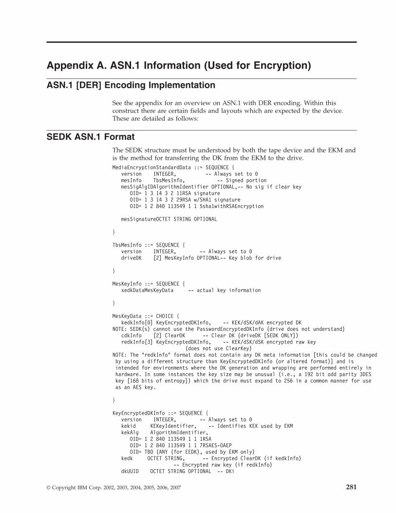
Appendix A. ASN.1 Information (Used for Encryption)
ASN.1 [DER] Encoding Implementation
See the appendix for an overview on ASN.1 with DER encoding. Within this
construct there are certain fields and layouts which are expected by the device.
These are detailed as follows:
SEDK ASN.1 Format
The SEDK structure must be understood by both the tape device and the EKM and
is the method for transferring the DK from the EKM to the drive.
MediaEncryptionStandardData ::= SEQUENCE {
version INTEGER, -- Always set to 0
mesInfo TbsMesInfo, -- Signed portion
mesSigAlgIDAlgorithmIdentifier OPTIONAL,-- No sig if clear key
OID= 1 3 14 3 2 11RSA signature
OID= 1 3 14 3 2 29RSA w/SHA1 signature
OID= 1 2 840 113549 1 1 5sha1withRSAEncryption
mesSignatureOCTET STRING OPTIONAL
}
TbsMesInfo ::= SEQUENCE {
version INTEGER, -- Always set to 0
driveDK [2] MesKeyInfo OPTIONAL-- Key blob for drive
}
MesKeyInfo ::= SEQUENCE {
xedkDataMesKeyData -- actual key information
}
MesKeyData ::= CHOICE {
kedkInfo[0] KeyEncryptedDKInfo, -- KEK/dSK/dAK encrypted DK
NOTE: SEDK(s) cannot use the PasswordEncryptedDKInfo (drive does not understand)
cdkInfo [2] ClearDK -- Clear DK (driveDK [SEDK ONLY])
redkInfo[3] KeyEncryptedDKInfo, -- KEK/dSK/dSK encrypted raw key
(does not use ClearKey)
NOTE: The "redkInfo" format does not contain any DK meta information [this could be changed
by using a different structure than KeyEncryptedDKInfo (or altered format)] and is
intended for environments where the DK generation and wrapping are performed entirely in
hardware. In some instances the key size may be unusual (i.e., a 192 bit odd parity 3DES
key [168 bits of entropy]) which the drive must expand to 256 in a common manner for use
as an AES key.
}
KeyEncryptedDKInfo ::= SEQUENCE {
version INTEGER, -- Always set to 0
kekid KEKeyIdentifier, -- Identifies KEK used by EKM
kekAlg AlgorithmIdentifier,
OID= 1 2 840 113549 1 1 1RSA
OID= 1 2 840 113549 1 1 7RSAES-OAEP
OID= TBD (ANY (for EEDK), used by EKM only)
kedk OCTET STRING, -- Encrypted ClearDK (if kedkInfo)
-- Encrypted raw key (if redkInfo)
dkUUID OCTET STRING OPTIONAL -- DKi
© Copyright IBM Corp. 2002, 2003, 2004, 2005, 2006, 2007 281

}
KEKeyIdentifier ::= CHOICE {
kekPublicDigest[0] DigestInfo-- Digest of public key,
OID= 1 3 14 3 2 26SHA-1
OID= 1 2 840 113549 2 7Legacy format
kekIssuerSNDigest[1] DigestInfo, -- Digest of DER encoded IssuerAndSerialNumber
kekLabel [2] IA5String(1::64)
}
ClearDK ::= SEQUENCE {
version INTEGER, -- Always set to 0
dataKeyAlg AlgorithmIdentifier, -- Algorithm used for data encryption
OID= 2 16 840 1 101 3 4 1AES (TBD 256-GCM specific?)
dataKey OCTET STRING -- The DK
dkUUID OCTET STRING OPTIONAL -- DKi
}
ASN.1 Standalone SEDK (SEDK only, clear, signed) - Example
ASN1 Data
Ofs Ofs Len: ASN.1 Field Name
0 4 356: SEQUENCE {
: <30 82 01 64>
4 6 1 : INTEGER 0 version
: <02 01 00>
7 9 76 : SEQUENCE {mesInfo:
<30 4B>
9 11 1 : INTEGER 0 version
: <02 01 00>
12 14 53 : [2] SEQUENCE { driveDK:
<A2 35>
14 16 69 : [2] SEQUENCE { cdkInfo
: <A2 45>
16 18 1 : INTEGER 0 version
: <02 01 00>
19 21 12 : SEQUENCE { dataKeyAlg
: <30 0C>
21 23 8 : OID 2 16 840 1 101 3 4 1:
<06 08 60 86 48 01 65 03 04 01>
31 33 0 : NULL
: <05 00>
: }
33 35 32 : OCTET STRING dataKey:
: ?? ?? ?? ?? ?? ?? ?? ?? ?? ?? ?? ?? ?? ?? ?? ??
: ?? ?? ?? ?? ?? ?? ?? ?? ?? ?? ?? ?? ?? ?? ?? ??
67 69 16 : OCTET STRING dkUUID (OPTIONAL)
: <04 10>
: }
: }
: }
85 87 13 : SEQUENCE {mesSigAlgID
: <30 0D>
87 89 9 : OID 1 2 840 113549 1 1 5
: <06 09 2A 86 48 86 F7 0D 01 01 05>
98 100 0 : NULL
: <05 00>
: }
100 104 256: OCTET STRING mesSignature
: <04 82 01 00>
: ?? ?? ?? ?? ?? ?? ?? ?? ?? ?? ?? ?? ?? ?? ?? ??
: ?? ?? ?? ?? ?? ?? ?? ?? ?? ?? ?? ?? ?? ?? ?? ??
: ?? ?? ?? ?? ?? ?? ?? ?? ?? ?? ?? ?? ?? ?? ?? ??
: ?? ?? ?? ?? ?? ?? ?? ?? ?? ?? ?? ?? ?? ?? ?? ??
282 IBM TotalStorage LTO Ultrium Tape Drive: SCSI Reference
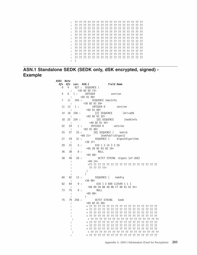
: ?? ?? ?? ?? ?? ?? ?? ?? ?? ?? ?? ?? ?? ?? ?? ??
: ?? ?? ?? ?? ?? ?? ?? ?? ?? ?? ?? ?? ?? ?? ?? ??
: ?? ?? ?? ?? ?? ?? ?? ?? ?? ?? ?? ?? ?? ?? ?? ??
: ?? ?? ?? ?? ?? ?? ?? ?? ?? ?? ?? ?? ?? ?? ?? ??
: ?? ?? ?? ?? ?? ?? ?? ?? ?? ?? ?? ?? ?? ?? ?? ??
: ?? ?? ?? ?? ?? ?? ?? ?? ?? ?? ?? ?? ?? ?? ?? ??
: ?? ?? ?? ?? ?? ?? ?? ?? ?? ?? ?? ?? ?? ?? ?? ??
: ?? ?? ?? ?? ?? ?? ?? ?? ?? ?? ?? ?? ?? ?? ?? ??
: ?? ?? ?? ?? ?? ?? ?? ?? ?? ?? ?? ?? ?? ?? ?? ??
: ?? ?? ?? ?? ?? ?? ?? ?? ?? ?? ?? ?? ?? ?? ?? ??
: ?? ?? ?? ?? ?? ?? ?? ?? ?? ?? ?? ?? ?? ?? ?? ??
: ?? ?? ?? ?? ?? ?? ?? ?? ?? ?? ?? ?? ?? ?? ?? ??
: }
ASN.1 Standalone SEDK (SEDK only, dSK encrypted, signed) -
Example
ASN1 Data
Ofs Ofs Len: ASN.1 Field Name
0 4 627 : SEQUENCE {
: <30 82 02 73>
4 6 1 : INTEGER version
: <02 01 00>
7 11 345 : SEQUENCE {mesInfo
: <30 82 01 59>
11 13 1 : INTEGER 0 version
: <02 01 00>
14 18 338 : [2] SEQUENCE {driveDK
: <A2 82 01 52>
18 22 334 : [0] SEQUENCE {kedkInfo
: <A0 82 01 4E>
22 24 1 : INTEGER 0 version
: <02 01 00>
25 27 33 : [0] SEQUENCE { kekid:
<A0 21> (kekPublicDigest)
27 29 31 : SEQUENCE { digestAlgorithm
: <30 1F>
29 31 5 : OID 1 3 14 3 2 26
: <05 2B 0E 03 02 1A>
36 38 0 : NULL
: <05 00>
38 40 20 : OCTET STRING digest (of dSK)
: <04 14>
: <?? ?? ?? ?? ?? ?? ?? ?? ?? ?? ?? ?? ?? ?? ?? ??
: ?? ?? ?? ??>
: }
: }
60 62 13 : SEQUENCE { kekAlg
: <30 0D>
62 64 9 : OID 1 2 840 113549 1 1 1
: <06 09 2A 86 48 86 F7 0D 01 01 01>
73 75 0 : NULL
: <05 00>
: }
75 79 256 : OCTET STRING kedk
: <04 82 01 00>
: < ?? ?? ?? ?? ?? ?? ?? ?? ?? ?? ?? ?? ?? ?? ?? ??
: < ?? ?? ?? ?? ?? ?? ?? ?? ?? ?? ?? ?? ?? ?? ?? ??
: < ?? ?? ?? ?? ?? ?? ?? ?? ?? ?? ?? ?? ?? ?? ?? ??
: < ?? ?? ?? ?? ?? ?? ?? ?? ?? ?? ?? ?? ?? ?? ?? ??
: < ?? ?? ?? ?? ?? ?? ?? ?? ?? ?? ?? ?? ?? ?? ?? ??
: < ?? ?? ?? ?? ?? ?? ?? ?? ?? ?? ?? ?? ?? ?? ?? ??
: < ?? ?? ?? ?? ?? ?? ?? ?? ?? ?? ?? ?? ?? ?? ?? ??
: < ?? ?? ?? ?? ?? ?? ?? ?? ?? ?? ?? ?? ?? ?? ?? ??
: < ?? ?? ?? ?? ?? ?? ?? ?? ?? ?? ?? ?? ?? ?? ?? ??
: < ?? ?? ?? ?? ?? ?? ?? ?? ?? ?? ?? ?? ?? ?? ?? ??
Appendix A. ASN.1 Information (Used for Encryption) 283
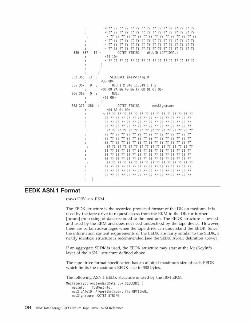
: < ?? ?? ?? ?? ?? ?? ?? ?? ?? ?? ?? ?? ?? ?? ?? ??
: < ?? ?? ?? ?? ?? ?? ?? ?? ?? ?? ?? ?? ?? ?? ?? ??
: < ?? ?? ?? ?? ?? ?? ?? ?? ?? ?? ?? ?? ?? ?? ?? ??
: < ?? ?? ?? ?? ?? ?? ?? ?? ?? ?? ?? ?? ?? ?? ?? ??
: < ?? ?? ?? ?? ?? ?? ?? ?? ?? ?? ?? ?? ?? ?? ?? ??
: < ?? ?? ?? ?? ?? ?? ?? ?? ?? ?? ?? ?? ?? ?? ?? ??
335 337 16 : OCTET STRING dkUUID (OPTIONAL)
: <04 10>
: < ?? ?? ?? ?? ?? ?? ?? ?? ?? ?? ?? ?? ?? ?? ?? ??
: }
: }
: }
353 355 13 : SEQUENCE {mesSigAlgID
: <30 0D>
355 357 9 : OID 1 2 840 113549 1 1 5
: <06 09 2A 86 48 86 F7 0D 01 01 05>
366 368 0 : NULL
: <05 00>
: }
368 372 256 : OCTET STRING mesSignature
: <04 82 01 00>
: < ?? ?? ?? ?? ?? ?? ?? ?? ?? ?? ?? ?? ?? ?? ?? ??
: ?? ?? ?? ?? ?? ?? ?? ?? ?? ?? ?? ?? ?? ?? ?? ??
: ?? ?? ?? ?? ?? ?? ?? ?? ?? ?? ?? ?? ?? ?? ?? ??
: ?? ?? ?? ?? ?? ?? ?? ?? ?? ?? ?? ?? ?? ?? ?? ??
: ?? ?? ?? ?? ?? ?? ?? ?? ?? ?? ?? ?? ?? ?? ?? ??
: ?? ?? ?? ?? ?? ?? ?? ?? ?? ?? ?? ?? ?? ?? ?? ??
: ?? ?? ?? ?? ?? ?? ?? ?? ?? ?? ?? ?? ?? ?? ?? ??
: ?? ?? ?? ?? ?? ?? ?? ?? ?? ?? ?? ?? ?? ?? ?? ??
: ?? ?? ?? ?? ?? ?? ?? ?? ?? ?? ?? ?? ?? ?? ?? ??
: ?? ?? ?? ?? ?? ?? ?? ?? ?? ?? ?? ?? ?? ?? ?? ??
: ?? ?? ?? ?? ?? ?? ?? ?? ?? ?? ?? ?? ?? ?? ?? ??
: ?? ?? ?? ?? ?? ?? ?? ?? ?? ?? ?? ?? ?? ?? ?? ??
: ?? ?? ?? ?? ?? ?? ?? ?? ?? ?? ?? ?? ?? ?? ?? ??
: ?? ?? ?? ?? ?? ?? ?? ?? ?? ?? ?? ?? ?? ?? ?? ??
: ?? ?? ?? ?? ?? ?? ?? ?? ?? ?? ?? ?? ?? ?? ?? ??
: ?? ?? ?? ?? ?? ?? ?? ?? ?? ?? ?? ?? ?? ?? ?? ??
: }
EEDK ASN.1 Format
(raw) DRV <-> EKM
The EEDK structure is the recorded protected format of the DK on medium. It is
used by the tape drive to request access from the EKM to the DK for further
[future] processing of data recorded to the medium. The EEDK structure is owned
and used by the EKM and does not need understood by the tape device. However,
there are certain advantages when the tape drive can understand the EEDK. Since
the information content requirements of the EEDK are fairly similar to the SEDK, a
nearly identical structure is recommended [see the SEDK ASN.1 definition above].
If an aggregate SEDK is used, the EEDK structure may start at the MesKeyInfo
layer of the ASN.1 structure defined above.
The tape drive format specification has an allotted maximum size of each EEDK
which limits the maximum EEDK size to 380 bytes.
The following ASN.1 EEDK structure is used by the IBM EKM.
MediaEncryptionStandardData ::= SEQUENCE {
mesInfo TbsMesInfo,
mesSigAlgID AlgorithmIndentifierOPTIONAL,
mesSignature OCTET STRING
284 IBM TotalStorage LTO Ultrium Tape Drive: SCSI Reference
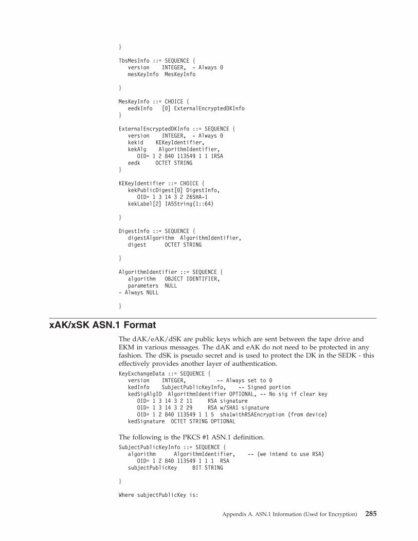
}
TbsMesInfo ::= SEQUENCE {
version INTEGER, - Always 0
mesKeyInfo MesKeyInfo
}
MesKeyInfo ::= CHOICE {
eedkInfo [0] ExternalEncryptedDKInfo
}
ExternalEncryptedDKInfo ::= SEQUENCE {
version INTEGER, - Always 0
kekid KEKeyIdentifier,
kekAlg AlgorithmIdentifier,
OID= 1 2 840 113549 1 1 1RSA
eedk OCTET STRING
}
KEKeyIdentifier ::= CHOICE {
kekPublicDigest[0] DigestInfo,
OID= 1 3 14 3 2 26SHA-1
kekLabel[2] IA5String(1::64)
}
DigestInfo ::= SEQUENCE {
digestAlgorithm AlgorithmIdentifier,
digest OCTET STRING
}
AlgorithmIdentifier ::= SEQUENCE {
algorithm OBJECT IDENTIFIER,
parameters NULL
- Always NULL
}
xAK/xSK ASN.1 Format
The dAK/eAK/dSK are public keys which are sent between the tape drive and
EKM in various messages. The dAK and eAK do not need to be protected in any
fashion. The dSK is pseudo secret and is used to protect the DK in the SEDK - this
effectively provides another layer of authentication.
KeyExchangeData ::= SEQUENCE {
version INTEGER, -- Always set to 0
kedInfo SubjectPublicKeyInfo, -- Signed portion
kedSigAlgID AlgorithmIdentifier OPTIONAL, -- No sig if clear key
OID= 1 3 14 3 2 11 RSA signature
OID= 1 3 14 3 2 29 RSA w/SHA1 signature
OID= 1 2 840 113549 1 1 5 sha1withRSAEncryption (from device)
kedSignature OCTET STRING OPTIONAL
The following is the PKCS #1 ASN.1 definition.
SubjectPublicKeyInfo ::= SEQUENCE {
algorithm AlgorithmIdentifier, -- (we intend to use RSA)
OID= 1 2 840 113549 1 1 1 RSA
subjectPublicKey BIT STRING
}
Where subjectPublicKey is:
Appendix A. ASN.1 Information (Used for Encryption) 285

RSAPublicKey ::= SEQUENCE {
modulus INTEGER, -- n
publicExponent INTEGER -- e
}
ASN.1 xAK/xSK Structure (clear, signed) - Example
ASN1 Data
Ofs Ofs Len: ASN.1 Field Name
0 4 572 : SEQUENCE {
: <30 82 02 73>
4 6 1 : INTEGER 0 version
: <02 01 00>
7 11 290-: SEQUENCE { kedInfo
: <30 82 01 22> (may be 21)
11 13 13 : SEQUENCE { algorithm
: <30 0B>
13 15 9 : OID 1 2 840 113549 1 1 1
: <06 09 2A 86 48 86 F7 0D 01 01 01>
24 26 0 : NULL
: <05 00>
: }
26 30 271-: BIT STRING (0 unused bits) {subjectPublicKey
: <03 82 01 0F>
: <00>
31 35 266-: SEQUENCE { RSA key
: <30 82 01 0A> (may be 09)
35 39 257-: INTEGER modulus
: <02 82 01 01> (may be 00 [need to add 00 if msb=1])
: <[00]
: ?? ?? ?? ?? ?? ?? ?? ?? ?? ?? ?? ?? ?? ?? ?? ??
: ?? ?? ?? ?? ?? ?? ?? ?? ?? ?? ?? ?? ?? ?? ?? ??
: ?? ?? ?? ?? ?? ?? ?? ?? ?? ?? ?? ?? ?? ?? ?? ??
: ?? ?? ?? ?? ?? ?? ?? ?? ?? ?? ?? ?? ?? ?? ?? ??
: ?? ?? ?? ?? ?? ?? ?? ?? ?? ?? ?? ?? ?? ?? ?? ??
: ?? ?? ?? ?? ?? ?? ?? ?? ?? ?? ?? ?? ?? ?? ?? ??
: ?? ?? ?? ?? ?? ?? ?? ?? ?? ?? ?? ?? ?? ?? ?? ??
: ?? ?? ?? ?? ?? ?? ?? ?? ?? ?? ?? ?? ?? ?? ?? ??
: ?? ?? ?? ?? ?? ?? ?? ?? ?? ?? ?? ?? ?? ?? ?? ??
: ?? ?? ?? ?? ?? ?? ?? ?? ?? ?? ?? ?? ?? ?? ?? ??
: ?? ?? ?? ?? ?? ?? ?? ?? ?? ?? ?? ?? ?? ?? ?? ??
: ?? ?? ?? ?? ?? ?? ?? ?? ?? ?? ?? ?? ?? ?? ?? ??
: ?? ?? ?? ?? ?? ?? ?? ?? ?? ?? ?? ?? ?? ?? ?? ??
: ?? ?? ?? ?? ?? ?? ?? ?? ?? ?? ?? ?? ?? ?? ?? ??
: ?? ?? ?? ?? ?? ?? ?? ?? ?? ?? ?? ?? ?? ?? ?? ??
: ?? ?? ?? ?? ?? ?? ?? ?? ?? ?? ?? ?? ?? ?? ?? ??>
296- 298- 3 : INTEGER publicExponent
: <02 03>
: <01 00 01>
: }
: }
: }
301- 303- 13 : SEQUENCE {kedSigAlgID
: <30 0D>
303- 305- 9 : OID 1 2 840 113549 1 1 5
: <06 09 2A 86 48 86 F7 0D 01 01 05>
314- 316- 0 : NULL
: <05 00>
: }
316- 318- 256 : OCTET STRING kedSignature
: <04 82 01 00>
: ?? ?? ?? ?? ?? ?? ?? ?? ?? ?? ?? ?? ?? ?? ?? ??
: ?? ?? ?? ?? ?? ?? ?? ?? ?? ?? ?? ?? ?? ?? ?? ??
: ?? ?? ?? ?? ?? ?? ?? ?? ?? ?? ?? ?? ?? ?? ?? ??
: ?? ?? ?? ?? ?? ?? ?? ?? ?? ?? ?? ?? ?? ?? ?? ??
286 IBM TotalStorage LTO Ultrium Tape Drive: SCSI Reference
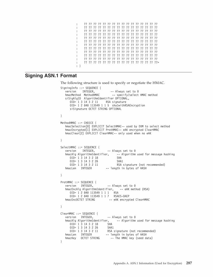
: ?? ?? ?? ?? ?? ?? ?? ?? ?? ?? ?? ?? ?? ?? ?? ??
: ?? ?? ?? ?? ?? ?? ?? ?? ?? ?? ?? ?? ?? ?? ?? ??
: ?? ?? ?? ?? ?? ?? ?? ?? ?? ?? ?? ?? ?? ?? ?? ??
: ?? ?? ?? ?? ?? ?? ?? ?? ?? ?? ?? ?? ?? ?? ?? ??
: ?? ?? ?? ?? ?? ?? ?? ?? ?? ?? ?? ?? ?? ?? ?? ??
: ?? ?? ?? ?? ?? ?? ?? ?? ?? ?? ?? ?? ?? ?? ?? ??
: ?? ?? ?? ?? ?? ?? ?? ?? ?? ?? ?? ?? ?? ?? ?? ??
: ?? ?? ?? ?? ?? ?? ?? ?? ?? ?? ?? ?? ?? ?? ?? ??
: ?? ?? ?? ?? ?? ?? ?? ?? ?? ?? ?? ?? ?? ?? ?? ??
: ?? ?? ?? ?? ?? ?? ?? ?? ?? ?? ?? ?? ?? ?? ?? ??
: ?? ?? ?? ?? ?? ?? ?? ?? ?? ?? ?? ?? ?? ?? ?? ??
: ?? ?? ?? ?? ?? ?? ?? ?? ?? ?? ?? ?? ?? ?? ?? ??>
: }
Signing ASN.1 Format
The following structure is used to specify or negotiate the HMAC.
SigningInfo ::= SEQUENCE {
version INTEGER, -- Always set to 0
hmacMethod MethodHMAC -- specify/select HMAC method
siSigAlgID AlgorithmIdentifier OPTIONAL,
OID= 1 3 14 3 2 11 RSA signature
OID= 1 2 840 113549 1 1 5 sha1withRSAEncryption
siSignature OCTET STRING OPTIONAL
}
MethodHMAC ::= CHOICE {
hmacSelection[0] EXPLICIT SelectHMAC-- used by EKM to select method
hmacEncrypted[1] EXPLICIT ProtHMAC-- eAK encrypted ClearHMAC
hmacClear[2] EXPLICIT ClearHMAC-- only used when no eAK
}
SelectHMAC ::= SEQUENCE {
version INTEGER, -- Always set to 0
hmacAlg AlgorithmIdentifier, -- Algorithm used for message hashing
OID= 1 3 14 3 2 18 SHA
OID= 1 3 14 3 2 26 SHA1
OID= 1 3 14 3 2 11 RSA signature (not recommended)
hmacLen INTEGER -- length in bytes of HASH
}
ProtHMAC ::= SEQUENCE {
version INTEGER, -- Always set to 0
hmacEncAlg AlgorithmIdentifier, -- eAK method (RSA)
OID= 1 2 840 113549 1 1 1 RSA
OID= 1 2 840 113549 1 1 7 RSAES-OAEP
hmacEncOCTET STRING -- eAK encrypted ClearHMAC
}
ClearHMAC ::= SEQUENCE {
version INTEGER, -- Always set to 0
hmacAlg AlgorithmIdentifier, -- Algorithm used for message hashing
OID= 1 3 14 3 2 18 SHA
OID= 1 3 14 3 2 26 SHA1
OID= 1 3 14 3 2 11 RSA signature (not recommended)
hmacLen INTEGER -- length in bytes of HASH
hmacKey OCTET STRING -- The HMAC key (seed data)
}
Appendix A. ASN.1 Information (Used for Encryption) 287

ASN.1 Signing Information (clear, unsigned) - Example
ASN1 Data
Ofs Ofs Len: ASN.1 Field Name
0 2 56 : SEQUENCE {
: <30 38>
2 4 1 : INTEGER 0 version
: <02 01 00>
5 7 51 : [2] SEQUENCE { hmacClear
: <A2 33>
7 9 1 : INTEGER 0 version
: <02 01 00>
10 12 9 : SEQUENCE {hmacAlg
: <30 09>
12 14 5 : OID 1 3 14 3 2 18
: <06 05 2B 0E 03 02 12>
19 21 0 : NULL
: <05 00>
: }
21 23 1 : INTEGER 32 hmacLen
: <05 01 20>
24 26 32 : OCTET STRING hmacKey
: <04 20>
: <?? ?? ?? ?? ?? ?? ?? ?? ?? ?? ?? ?? ?? ?? ?? ??
: ?? ?? ?? ?? ?? ?? ?? ?? ?? ?? ?? ?? ?? ?? ?? ??>
: }
: }
ASN.1 Signing Information (eAK encrypted, dAK signed) - Example
ASN1 Data
Ofs Ofs Len: ASN.1 Field Name
0 4 560: SEQUENCE {
: <30 82 02 30> version
4 6 1 : INTEGER 0
: <02 01 00>
7 11 278: [1] SEQUENCE { hmacEncrypted
: <A1 82 01 16>
11 13 1 : INTEGER 0 version
: <02 01 00>
14 16 13 : SEQUENCE { hmacEncAlg
: <30 0D>
16 18 9 : OID 1 2 840 113549 1 1 1
: <06 09 2A 86 48 86 F7 0D 01 01 01>
27 29 0 : NULL
: <05 00>
: }
29 33 256: OCTET STRING hmacEnc (w/eAK)
: <04 82 01 00>
: <?? ?? ?? ?? ?? ?? ?? ?? ?? ?? ?? ?? ?? ?? ?? ??
: ?? ?? ?? ?? ?? ?? ?? ?? ?? ?? ?? ?? ?? ?? ?? ??
: ?? ?? ?? ?? ?? ?? ?? ?? ?? ?? ?? ?? ?? ?? ?? ??
: ?? ?? ?? ?? ?? ?? ?? ?? ?? ?? ?? ?? ?? ?? ?? ??
: ?? ?? ?? ?? ?? ?? ?? ?? ?? ?? ?? ?? ?? ?? ?? ??
: ?? ?? ?? ?? ?? ?? ?? ?? ?? ?? ?? ?? ?? ?? ?? ??
: ?? ?? ?? ?? ?? ?? ?? ?? ?? ?? ?? ?? ?? ?? ?? ??
: ?? ?? ?? ?? ?? ?? ?? ?? ?? ?? ?? ?? ?? ?? ?? ??
: ?? ?? ?? ?? ?? ?? ?? ?? ?? ?? ?? ?? ?? ?? ?? ??
: ?? ?? ?? ?? ?? ?? ?? ?? ?? ?? ?? ?? ?? ?? ?? ??
: ?? ?? ?? ?? ?? ?? ?? ?? ?? ?? ?? ?? ?? ?? ?? ??
: ?? ?? ?? ?? ?? ?? ?? ?? ?? ?? ?? ?? ?? ?? ?? ??
: ?? ?? ?? ?? ?? ?? ?? ?? ?? ?? ?? ?? ?? ?? ?? ??
: ?? ?? ?? ?? ?? ?? ?? ?? ?? ?? ?? ?? ?? ?? ?? ??
: ?? ?? ?? ?? ?? ?? ?? ?? ?? ?? ?? ?? ?? ?? ?? ??
: ?? ?? ?? ?? ?? ?? ?? ?? ?? ?? ?? ?? ?? ?? ?? ??>
: }
288 IBM TotalStorage LTO Ultrium Tape Drive: SCSI Reference
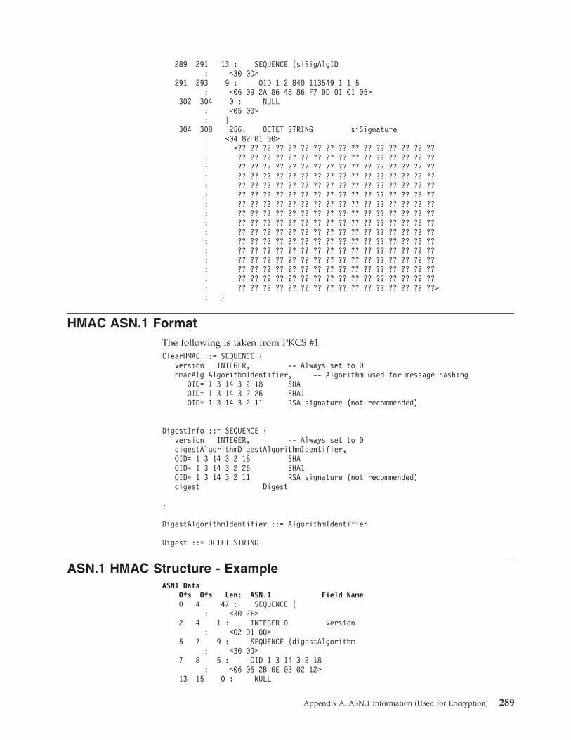
289 291 13 : SEQUENCE {siSigAlgID
: <30 0D>
291 293 9 : OID 1 2 840 113549 1 1 5
: <06 09 2A 86 48 86 F7 0D 01 01 05>
302 304 0 : NULL
: <05 00>
: }
304 308 256: OCTET STRING siSignature
: <04 82 01 00>
: <?? ?? ?? ?? ?? ?? ?? ?? ?? ?? ?? ?? ?? ?? ?? ??
: ?? ?? ?? ?? ?? ?? ?? ?? ?? ?? ?? ?? ?? ?? ?? ??
: ?? ?? ?? ?? ?? ?? ?? ?? ?? ?? ?? ?? ?? ?? ?? ??
: ?? ?? ?? ?? ?? ?? ?? ?? ?? ?? ?? ?? ?? ?? ?? ??
: ?? ?? ?? ?? ?? ?? ?? ?? ?? ?? ?? ?? ?? ?? ?? ??
: ?? ?? ?? ?? ?? ?? ?? ?? ?? ?? ?? ?? ?? ?? ?? ??
: ?? ?? ?? ?? ?? ?? ?? ?? ?? ?? ?? ?? ?? ?? ?? ??
: ?? ?? ?? ?? ?? ?? ?? ?? ?? ?? ?? ?? ?? ?? ?? ??
: ?? ?? ?? ?? ?? ?? ?? ?? ?? ?? ?? ?? ?? ?? ?? ??
: ?? ?? ?? ?? ?? ?? ?? ?? ?? ?? ?? ?? ?? ?? ?? ??
: ?? ?? ?? ?? ?? ?? ?? ?? ?? ?? ?? ?? ?? ?? ?? ??
: ?? ?? ?? ?? ?? ?? ?? ?? ?? ?? ?? ?? ?? ?? ?? ??
: ?? ?? ?? ?? ?? ?? ?? ?? ?? ?? ?? ?? ?? ?? ?? ??
: ?? ?? ?? ?? ?? ?? ?? ?? ?? ?? ?? ?? ?? ?? ?? ??
: ?? ?? ?? ?? ?? ?? ?? ?? ?? ?? ?? ?? ?? ?? ?? ??
: ?? ?? ?? ?? ?? ?? ?? ?? ?? ?? ?? ?? ?? ?? ?? ??>
: }
HMAC ASN.1 Format
The following is taken from PKCS #1.
ClearHMAC ::= SEQUENCE {
version INTEGER, -- Always set to 0
hmacAlg AlgorithmIdentifier, -- Algorithm used for message hashing
OID= 1 3 14 3 2 18 SHA
OID= 1 3 14 3 2 26 SHA1
OID= 1 3 14 3 2 11 RSA signature (not recommended)
DigestInfo ::= SEQUENCE {
version INTEGER, -- Always set to 0
digestAlgorithmDigestAlgorithmIdentifier,
OID= 1 3 14 3 2 18 SHA
OID= 1 3 14 3 2 26 SHA1
OID= 1 3 14 3 2 11 RSA signature (not recommended)
digest Digest
}
DigestAlgorithmIdentifier ::= AlgorithmIdentifier
Digest ::= OCTET STRING
ASN.1 HMAC Structure - Example
ASN1 Data
Ofs Ofs Len: ASN.1 Field Name
0 4 47 : SEQUENCE {
: <30 2F>
2 4 1 : INTEGER 0 version
: <02 01 00>
5 7 9 : SEQUENCE {digestAlgorithm
: <30 09>
7 8 5 : OID 1 3 14 3 2 18
: <06 05 2B 0E 03 02 12>
13 15 0 : NULL
Appendix A. ASN.1 Information (Used for Encryption) 289

: <05 00>
: }
15 17 32 : OCTET STRING digest
: <04 20>
: ?? ?? ?? ?? ?? ?? ?? ?? ?? ?? ?? ?? ?? ?? ?? ??
: ?? ?? ?? ?? ?? ?? ?? ?? ?? ?? ?? ?? ?? ?? ?? ??>
: }
290 IBM TotalStorage LTO Ultrium Tape Drive: SCSI Reference
Appendix B. Notices
Trademarks
The following terms are trademarks of International Business Machines
Corporation in the United States or other countries (or regions) or both:
AIX OS/400 pSeries
AS/400 pSeries RAA
eServer SP zSeries
IBM RS/6000 NetBackup (NBU)
iSeries TotalStorage
The following are U. S. trademarks of Hewlett-Packard Company, International
Business Machines Corporation, and Seagate Technology:
Linear Tape-Open
LTO
Ultrium
Intel and Itanium are registered trademarks of Intel Corporation in the United
States, or other countries (or regions), or both.
Linux is a register traefmark of Linus Torvalds.
NetBackup is a trademark of Symantec
Microsoft®, Windows®, Windows NT, and the Windows logo are registered
trademarks of Microsoft Corporation in the United States, or other countries (or
regions), or both.
Other company, product, and service names may be trademarks or service marks
of others.
© Copyright IBM Corp. 2002, 2003, 2004, 2005, 2006, 2007 291

292 IBM TotalStorage LTO Ultrium Tape Drive: SCSI Reference

Glossary
This glossary defines the special terms,
abbreviations, and acronyms that are used in this
publication.
Numbers and Symbols
2:1 compression. The relationship between the
quantity of data that can be stored with compression as
compared to the quantity of data that can be stored
without compression. In 2:1 compression, twice as
much data can be stored with compression as can be
stored without compression.
A
adapter. See adapter card.
adapter card. A circuit board that adds function to a
computer.
AL_PA. See Arbitrated Loop Physical Address.
Arbitrated Loop Physical Address (AL_PA). An 8-bit
value that identifies a device in an arbitrated loop. All
Fibre Channel ports communicate by using AL_PAs.
B
backups. The short-term retention of records used for
restoring essential business and server files when vital
data has been lost because of program or server errors
or malfunctions.
bezel. The removable frame that fits over the front of
the Ultrium Tape Drives.
bit. The smallest unit of data in a computer. A bit
(short for binary digit) has a single binary value (either
0 or 1). Computers store data and execute instructions
in bit multiples called bytes. In most computer systems,
there are eight bits in a byte.
bus. See SCSI bus.
byte. A string that consists of a certain number of bits
(usually 8) which are treated as a unit and represent a
character. A byte is a fundamental unit of data.
C
capacity. The amount of data that can be contained on
storage media and expressed in bytes.
cartridge. See tape cartridge.
cartridge memory. See LTO cartridge memory.
circuit board. A thin sheet on which chips and other
electronic components are placed. Computers consist of
one or more boards, often called cards or adapters.
cleaning cartridge. A tape cartridge that is used to
clean the heads of a tape drive. Contrast with data
cartridge.
command timeout. Following the issuance of a
command, a period of time during which it is
determined that there is a bad connection between the
server and the drive.
compression. The process of eliminating gaps, empty
fields, redundancies, and unnecessary data to shorten
the length of records or blocks.
configure. To describe to a server the devices, optional
features, and programs installed on the system.
D
data. Any representations such as characters or analog
quantities to which meaning is, or might be, assigned.
data cartridge. A tape cartridge that is dedicated to
storing data. Contrast with cleaning cartridge.
data compression. See compression.
data transfer rate. The average number of bits,
characters, or blocks per unit of time that pass between
corresponding equipment in a data transmission
system. The rate is expressed in bits, characters, or
blocks per second, minute, or hour.
device. Any hardware component or peripheral, such
as a tape drive or tape library, that can receive and
send data.
device driver. A binary file that is installed on a host
system and enables the host system to access a device.
diagnostic. A software program that is designed to
recognize, locate, and explain faults in equipment or
errors in programs.
diagnostic cartridge. A tape cartridge that enables the
detection and isolation of errors in programs and faults
in equipment.
drive. See IBM Ultrium Internal Tape Drive Models T200
and T200F or IBM TotalStorage LTO Ultrium 2 Tape Drive
Models T400 and T400F.
© Copyright IBM Corp. 2002, 2003, 2004, 2005, 2006, 2007 293
drive dump. The recording, at a particular instant, of
the contents of all or part of one storage device into
another storage device, usually as a safeguard against
faults or errors, or in connection with debugging.
drive head. The component that records an electrical
signal onto magnetic tape, or reads a signal from tape
into an electrical signal.
drive sense data. See SCSI drive sense data.
dump. See drive dump.
duplex. See duplex transmission.
duplex adapter. A mechanism that allows a device to
send and receive communication at the same time.
duplex transmission. Transmission in both directions,
either one direction at a time (half-duplex) or both
directions simultaneously (full-duplex).
E
eject. To remove or force out from within.
electronic mail. Correspondence in the form of
messages transmitted between user terminals over a
computer network.
e-mail. See electronic mail.
enclosure. A device, such as a desktop unit, tape
cartridge autoloader, or tape library, into which you can
install an Ultrium Tape Drive.
error log. Maintained by an Ultrium Tape Drive, a list
that contains the ten most recent error codes. The codes
identify errors that pertain to the drive.
F
Fibre Channel. A 100-MB-per-second, full-duplex,
serial communications technology that is capable of
interconnecting Ultrium Tape Drives and servers which
are separated by as much as 11 kilometers (7 miles).
Fibre Channel technology combines features of the
input/output (I/O) and networking interfaces.
Fibre Channel cable. The cable that connects a Fibre
Channel tape drive to another device. The conductive
element within the cable is constructed of either copper
wires or optical fibers. Generally, copper wires are used
for short distances (up to 30 meters or 98 feet); optical
fibers are used for longer distances. Fiber-optic cabling
is referred to by mode or the frequencies of light waves
that are carried by a particular cable type. Multimode
fiber cables are generally used for distances up to 500
meters (1640 feet) and with short-wave (780 nanometer)
laser light. Single-mode fiber cables are used for
distances greater than 500 m (1640 feet) and with
long-wave (1300 nanometer) laser light.
file. A named set of records that are stored or
processed as a unit.
filemark. Located on the magnetic tape within a tape
cartridge, a recorded element that typically marks the
organizational boundaries in a serial file structure (such
as directory boundaries) and that is requested to be
written or read by the server.
firmware. Proprietary code that is usually delivered as
part of an operating system. Firmware is more efficient
than software that is loaded from an alterable medium,
and is more adaptable to change than pure hardware
circuitry. An example of firmware is the Basic
Input/Output System (BIOS) in read-only memory
(ROM) on a PC motherboard.
G
Gb. See gigabit.
GB. See gigabyte.
gigabit (Gb). 1 000 000 000 bits.
gigabyte (GB). 1 000 000 000 bytes.
H
hard addressing. Pertaining to the Fibre Channel
drives (Models T200F and T400F), a method that
identifies the drive’s LID and, consequently, its AL_PA
(the AL_PA enables the drive to communicate with
other devices).
hardware. The physical equipment or devices that
form a computer.
head. See drive head.
host. The controlling or highest-level system in a data
communication configuration. Synonymous with server.
I
IBM Ultrium Internal Tape Drive Models T200 and
T200F. A data-storage device that controls the
movement of the magnetic tape in an IBM LTO Ultrium
Tape Cartridge. The drive houses the mechanism (drive
head) that reads and writes data to the tape. Its native
data capacity is 100 GB per cartridge and up to 200 GB
at 2:1 compression. Its native data transfer rate is 15
MB per second and 30 MB per second at 2:1
compression.
IBM TotalStorage LTO Ultrium 2 Tape Drive Models
T400 and T400F. A data-storage device that controls
the movement of the magnetic tape in an IBM LTO
Ultrium Tape Cartridge. The drive houses the
mechanism (drive head) that reads and writes data to
the tape. Its native data capacity is 200 GB per
294 IBM TotalStorage LTO Ultrium Tape Drive: SCSI Reference
cartridge and up to 400 GB at 2:1 compression. Its
native data transfer rate is 35 MB per second and 70
MB per second at 2:1 compression.
ID. Identifier.
initiator. In SCSI terms, a SCSI device that requests an
I/O process to be performed by another SCSI device (a
target). In many cases, an initiator can also be a target.
input/output (I/O). Data that is provided to a
computer or data that results from computer
processing.
install. (1) To set up for use or service. (2) The act of
adding a product, feature, or function to a server or
device either by a singular change or by the addition of
multiple components or devices.
Internet. The worldwide collection of interconnected
networks that use the Internet suite of protocols and
permit public access.
I/O. See input/output.
J
jumper. (1) A tiny connector that fits over a pair of
protruding pins in a connector. A jumper can be moved
to change electrical connectors. When in place, the
jumper connects the pins electrically. (2) To place a
jumper on a connector pin.
L
Linear Tape-Open (LTO). A type of tape storage
technology developed by the IBM Corporation,
Hewlett-Packard, and Seagate. LTO technology is an
“open format” technology, which means that its users
have multiple sources of product and media. The
“open” nature of LTO technology enables compatibility
between different vendors’ offerings by ensuring that
vendors comply with verification standards.
load. Following the insertion of a tape cartridge into
the tape load compartment, the act of positioning the
tape (performed by the tape drive) for reading or
writing by the drive’s head.
load and unload cycle. The act of inserting a cartridge
into a tape drive, loading the tape to load point,
rewinding the tape into the cartridge, and ejecting the
cartridge from the drive.
log sense data. See SCSI log sense data.
Low Voltage Differential (LVD). A low-noise,
low-power, and low-amplitude electrical signaling
system that enables data communication between a
supported server and the Ultrium Tape Drive. LVD
signaling uses two wires to drive one signal over
copper wire. The use of wire pairs reduces electrical
noise and crosstalk.
LTO. See Linear Tape-Open.
LTO cartridge memory (LTO-CM). Within each LTO
Ultrium Data Cartridge, an embedded electronics and
interface module that can store and retrieve a
cartridge’s historical usage and other information.
LTO-CM. See LTO cartridge memory.
LTO-DC. See LTO Data Compression.
LTO Data Compression (LTO-DC). A method that
compresses a server’s data before the drive writes it to
tape. LTO-DC detects but does not recompress or test
record boundaries and file markers (which are encoded
as control symbols). It also allows switching between
compression and no compression within the data
stream, which prevents data from expanding when the
drive compresses random or encrypted data.
LVD. See Low Voltage Differential.
M
magnetic tape. A tape with a magnetizable surface
layer on which data can be stored by magnetic
recording.
MB. See megabyte.
media. The plural of medium.
media capacity. See capacity.
medium. A physical material in or on which data may
be represented, such as magnetic tape.
megabyte (MB). 1 000 000 bytes.
micrometer. One millionth of a meter (.000001 m).
Synonymous with micron. Abbreviated as µm.
micron. One millionth of a meter (.000001 m).
Synonymous with micrometer. Abbreviated as µm.
microsecond. One millionth of a second (.000001 s).
Abbreviated as µs.
millimeter (mm). One thousandth of a meter (.001 m).
millisecond (ms). One thousandth of a second (.001 s).
mm. See millimeter.
ms. See millisecond.
Model T200. The version of the IBM Ultrium Internal
Tape Drive that uses the SCSI interface, has a native
storage capacity of 100 GB, and a native data transfer
rate of 15 MB per second.
Glossary 295

Model T200F. The version of the IBM Ultrium Internal
Tape Drive that uses the Fibre Channel interface, has a
native storage capacity of 100 GB, and a native data
transfer rate of 15 MB per second.
Model T400. The version of the IBM TotalStorage LTO
Ultrium 2 Tape Drive that uses the SCSI interface, has a
native storage capacity of 200 GB, and a native data
transfer rate of 35 MB per second.
Model T400F. The version of the IBM TotalStorage
LTO Ultrium 2 Tape Drive that uses the Fibre Channel
interface, has a native storage capacity of 200 GB, and a
native data transfer rate of 35 MB per second.
N
N/A. Not applicable.
native storage capacity. The amount of data that can
be stored without compression on a tape cartridge.
native sustained data transfer rate. See data transfer
rate.
network. A configuration of data processing devices
and software that is connected for information
interchange.
network server. In a local area network, a personal
computer that provides access to files for all of the
workstations in the network.
node. In Fibre Channel technology, a communicating
device.
ntutil. Created by IBM, a utility program for LTO
devices that connect to Windows NT and Windows
2000. ntutil provides problem determination for
hardware or connections, assists with device and
medium changer recognition, forces dumps, loads new
firmware, sends and receives SCSI commands to and
from the hardware, and obtains SCSI sense data to use
in resolving errors.
O
offline. The operating condition that the Ultrium Tape
Drives are in when the server’s applications cannot
interact with it.
online. The operating condition that the Ultrium Tape
Drives are in when the server’s applications can
interact with it.
Open Systems. Computer systems whose standards
are not proprietary.
operating system. The master computer control
program that translates the user’s commands and
allows software application programs to interact with
the computer’s hardware.
P
parity. The state of being even-numbered or
odd-numbered. A parity bit is a binary number that is
added to a group of binary numbers to make the sum
of that group always odd (odd parity) or even (even
parity).
parity error. A transmission error that occurs when the
received data does not have the parity that is expected
by the receiving system. This usually occurs when the
sending and receiving systems have different parity
settings.
port. (1) A system or network access point for data
entry or exit. (2) A connector on a device to which
cables for other devices such as display stations and
printers are attached. (3) The representation of a
physical connection to hardware. A port is sometimes
referred to as an adapter; however, there can be more
than one port on an adapter.
power-off. To remove electrical power from a device.
power-on, powered-on. (1) To apply electrical power
to a device. (2) The state of a device when power has
been applied to it.
protocol. The meanings of, and the sequencing rules
for, requests and responses that are used to manage a
network, transfer data, and synchronize the states of
network components.
Q
quiesce. To put a device into a temporarily inactive or
inhibited state, but not remove it from the server.
R
read. To acquire or interpret data from a storage
device, from a data medium, or from another source.
reboot. To reinitialize the execution of a program by
repeating the initial program load (IPL) operation.
record. The smallest distinct set of data bytes that is
supplied from a server for processing and recording by
a tape drive, and the smallest distinct set of data to be
read from tape, reprocessed, and made available to a
server by a tape drive.
record boundaries. The fixed limits of a record.
repeater. A device that regenerates signals to extend
the range of transmission between data stations or to
interconnect two branches. A repeater is a node of a
local area network.
reset. To return a device or circuit to a clear state.
296 IBM TotalStorage LTO Ultrium Tape Drive: SCSI Reference
RS-422 connector. Located at the rear of the Ultrium
Tape Drive, the connector to which the internal RS-422
cable of an enclosure connects. The connection enables
serial devices to communicate with the drive.
RS-422 interface. An electrical interface standard that
is approved by the Electronic Industries Association
(EIA) for connecting serial devices. The RS-422
standard, which supports higher data rates and greater
immunity to electrical interference, is an alternative to
the older RS-232 interface, and uses individual
differential signal pairs for data transmission.
Depending on data transmission rates, RS-422 can be
used at distances up to 1,275 m (4,000 ft). The RS-422
interface also supports multi-point connections.
S
s. See second.
SAN. See Storage Area Network.
SAN Data Gateway. A device that provides Fibre
Channel attachment between Open Systems servers and
SCSI disk and tape storage systems.
SC. See subscription channel connector.
SCSI. See Small Computer Systems Interface.
SCSI bus. (1) A collection of wires through which
data is transmitted from one part of a computer to
another. (2) A generic term that refers to the complete
set of signals that define the activity of the Small
Computer Systems Interface (SCSI).
SCSI connector. Located at the rear of the Ultrium
Tape Drive, the connector that facilitates commands to
and from the server, and to which the internal SCSI
cable of an enclosure connects.
SCSI device. Anything that can connect into the SCSI
bus and actively participate in bus activity.
SCSI drive sense data. In response to inquiry from
the server about an error condition, a packet of SCSI
sense bytes that contains information about the error
and that is sent back to the server by the drive.
SCSI ID. The unique address (from 1 to 15) that you
assign to an Ultrium Tape Drive that uses a SCSI
interface.
SCSI ID connector. Located at the rear of the Ultrium
Tape Drive, the connector that enables the drive’s SCSI
address to be set. Addresses are determined by the
placement of jumpers on the pins.
SCSI ID switch. Located on an enclosure that
contains a Ultrium Tape Drive, a mechanism that
connects to the drive and allows you to change the
drive’s SCSI ID without using jumpers.
SCSI log sense data. In response to inquiry from the
server about the Ultrium Tape Drive’s error logs and
counters, a packet of SCSI sense bytes which contains
that information and which is sent back to the server
by the drive. Log sense data is used to diagnose
problems, especially if the problems are intermittent.
second. One sixtieth of a minute.
selection timeout. Following the selection of an option
(for example, a data transfer), the period of time during
which it is determined that there is a bad connection
between the server and the drive.
sense data. Data that describes an I/O error. Sense
data is presented to a server in response to a Sense I/O
command.
serial interface. An interface that sequentially or
consecutively executes two or more operations in a
single device, such as an arithmetic and logic operation.
server. A functional unit that provides services to one
or more clients over a network. Examples include a file
server, a print server, or a mail server. The IBM Eserver
pSeries, IBM Eserver iSeries, HP, and Sun are servers.
Synonymous with host.
short-wave cable. In Fibre Channel technology, a laser
cable that uses a wavelength of 780 nanometers and is
only compatible with multimode fiber.
Small Computer Systems Interface (SCSI). A
standard used by computer manufacturers for attaching
peripheral devices (such as tape drives, hard disks,
CD-ROM players, printers, and scanners) to computers
(servers). Pronounced ″scuzzy.″ Variations of the SCSI
interface provide for faster data transmission rates than
standard serial and parallel ports (up to 160 megabytes
per second). The variations include:
v Fast/Wide SCSI: Uses a 16-bit bus, and supports data
rates of up to 20 MBps.
v SCSI-1: Uses an 8-bit bus, and supports data rates of
4 MBps.
v SCSI-2: Same as SCSI-1, but uses a 50-pin connector
instead of a 25-pin connector, and supports multiple
devices.
v Ultra SCSI: Uses an 8- or 16-bit bus, and supports
data rates of 20 or 40 MBps.
v Ultra2 SCSI: Uses an 8- or 16-bit bus and supports
data rates of 40 or 80 MBps.
v Ultra3 SCSI: Uses a 16-bit bus and supports data
rates of 80 or 160 MBps.
v Ultra160 SCSI: Uses a 16-bit bus and supports data
rates of 160 MBps.
soft addressing. Pertaining to the Fibre Channel drive,
a method that enables the drive to dynamically
arbitrate its AL_PA with other Fibre Channel devices on
the loop. The AL_PA enables the drive to communicate
with other devices.
Glossary 297
software. Programs, procedures, rules, and any
associated documentation pertaining to the operation of
a computer system.
Storage Area Network (SAN). A high-speed
subnetwork of shared storage devices. A SAN’s
architecture makes all storage devices available to all
servers on a LAN or WAN. As more storage devices
are added to a SAN, they too will be accessible from
any server in the larger network. Because stored data
does not reside directly on any of a network’s servers,
server power is used for business applications, and
network capacity is released to the end user.
subscription channel connector (SC). A push-pull
type of optical connector that features high density, low
loss, low backreflection, and low cost.
switch. A network infrastructure component to which
multiple nodes attach. Unlike hubs, switches typically
have the ability to switch node connections from one to
another. A typical switch can facilitate several
simultaneous bandwidth transmissions between
different pairs of nodes.
T
TapeAlert. A patented technology and ANSI standard
that defines conditions and problems that are
experienced by tape drives.
TapeAlert flags. Status and error messages that are
generated by the TapeAlert utility and display on the
server’s console.
tape cartridge. A removable storage case that houses
belt-driven magnetic tape that is wound on a supply
reel and a takeup reel.
tape drive. See IBM Ultrium Internal Tape Drive Models
T200 and T200F or IBM TotalStorage LTO Ultrium 2 Tape
Drive Models T400 and T400F.
tape path. Within a tape drive, the channel in which
the media moves.
tapeutil. Created by IBM, a utility program for LTO
devices that connect to all supported servers except
Windows NT and Windows 2000. tapeutil provides
service aids for tape subsystems, offers a menu-driven
tool for exercising or testing IBM tape and medium
changer devices, and includes a command-line interface
that is convenient for use in shell scripts.
terminate. To prevent unwanted electrical signal
reflections by applying a device (known as a
terminator) that absorbs the energy from the
transmission line.
topology. In communications, the physical or logical
arrangement of nodes in a network, especially the
relationships among nodes and the links between them.
TotalStorage LTO Ultrium Tape Drive Models T400
and T400F. See IBM TotalStorage LTO Ultrium 2 Tape
Drive Models T400 and T400F.
transfer rate. See data transfer rate.
U
Ultrium Tape Drive. See IBM Ultrium Internal Tape
Drive Models T200 and T200F or IBM TotalStorage LTO
Ultrium 2 Tape Drive Models T400 and T400F.
Ultrium 2 Tape Drive. See IBM TotalStorage LTO
Ultrium 2 Tape Drive.
uniform resource locator (URL). The address of an
item on the World Wide Web. It includes the protocol
followed by the fully qualified domain name
(sometimes called the host name) and the request. The
web server typically maps the request portion of the
URL to a path and file name. For example, if the URL
is http://www.networking.ibm.com/nsg/nsgmain.htm,
the protocol is http; the fully qualified domain name is
www.networking.ibm.com; and the request is
/nsg/nsgmain.htm.
unload. The act (performed by the drive) of
unthreading tape from the drive’s internal tape path
and returning it (with the leader block) to the tape
cartridge.
URL. See uniform resource locator.
utility. See utility program.
universal time (UT). The time at longitude zero,
colloquially known as Greenwich Mean Time. See
http://aa.usno.navy.mil/faq/docs/UT.html.
utility program. A computer program that supports
computer processes. For example, a diagnostic
program, a trace program, or a sort program.
V
vital product data (VPD). Information about a
product. Among other details, the VPD may include a
model number, serial number, part number, or level of
firmware.
W
web. See World Wide Web.
World Wide Name. A unique, 8-byte identifier that is
assigned by IBM Manufacturing to each Ultrium Tape
Drive and used to identify a drive.
298 IBM TotalStorage LTO Ultrium Tape Drive: SCSI Reference
World Wide Web. A network of servers that contain
programs and files. Many of the files contain hypertext
links to other documents that are available through the
network.
write. To make a permanent or transient recording of
data in a storage device or on a data medium.
write protected. Applicable to a tape cartridge, the
condition that exists when some logical or physical
mechanism prevents a device from writing on the tape
in that cartridge.
Glossary 299

300 IBM TotalStorage LTO Ultrium Tape Drive: SCSI Reference
Index
Special characters(Not LTO1), REPORT SUPPORTED TASK
MANAGEMENT FUNCTIONS 185
Aabort condition, handling 266
AS/400device driver support 4
requirements for attaching tape drive
to 3
ASN.1 [DER] Encoding
Implementation 281
ASN.1 HMAC Structure - Example 289
ASN.1 Information 281
ASN.1 Signing Information (clear,
unsigned) - Example 288
ASN.1 Signing Information (eAK
encrypted, dAK signed) - Example 288
ASN.1 Standalone SEDK (SEDK only,
clear, signed) - Example 282
ASN.1 Standalone SEDK (SEDK only,
dSK encrypted, signed) - Example 283
ASN.1 xAK/xSK Structure (clear, signed)
- Example 286
attaching tape drive to server 3
Attachment Features 265
Bbackward error page 85
Blocks/Bytes Transferred log page 95
burst data transfer rate 2
Bus Parity Errors (when using
Information unit transfers) 270
bus parity errors, handling 269
Ccapacity 2, 5
Clean Behavior (Byte 3) 133
Clear FLASH Dump (EEPROM) 227
Command Behavior When WORM
Medium Has Been Tampered With 251
Command Descriptor Block (CDB) 17
command(s)ERASE 20
INQUIRY 21
LOAD/UNLOAD 45
LOCATE 47
LOG SELECT 49
LOG SENSE 50
supported SCSI 17
compatible tape cartridges 5
compressed capacity 2
Conditions for Writing 251
Control Extension Mode Page 113
Current Sense data 245
DData Cartridge Emulates WORM
(01h) 134
Data Compression Log 80
Data Compression Mode Page 114
Data Encryption Algorithm Descriptor -
Standard Encryption 198
data transfer rate 2
Deferred Sense data 245
description of tape drives 1
Device Clocks 249
device drivers, supported 4
Device Hardware Encryption (Ultrium
4) 263
Device Identification Page 40
disconnect strategy 270
Disconnect/Reconnect Page 112
Download Process 279
Download, Firmware 277
Identifying Level Hardware of
Drive 277
Drive Component Revision Level
Pages 44
EEEDK ASN.1 Format 284
Encryption 281
Encryption Setup for Reading and
Appending (IBM Proprietary -
Application Method) 265
ERASE command 17, 20
Error Log Buffer (06h) 172
Error Log Buffer (06h)r 170
error sense information 245
errorsbus parity 269
persistent 246
FFeatures of the Serial Attached SCSI
(SAS) Interface 268
Fence Behavior (Byte 2) 131
Fencing Behavior 246
Fibre Channel attachmentabort condition, handling 265, 266
features of interface 275
LUN behaviors 265
multi-initiator support 265, 268
power-on procedure 265
requirements 3
reset strategy 265
status codes 265, 268
Fibre Channel Logical Unit Control
Page 119
Firmware Download 277
Identifying Level HardwareFirmware image is intended 279
Firmware Download (continued)Identifying Level Hardware of
Drive 277
Firmware Update Behavior (Byte 7) 135
Force Dump diagnostic 223
Format for the Attribute List Service
Action 153
Format for the Attribute Values Service
Action 152
Format for the Partition List Service
Action 155
Format for the Volume List Service
Action 154
FUNCTIONS (Not LTO1), REPORT
SUPPORTED TASK
MANAGEMENT 185
HHewlett-Packard
device driver support 4
requirements for attaching tape drive
to 3
high voltage differential (HVD) SCSI
interface 1, 2
HMAC ASN.1 Format 289
Host Port 0 Interface Errors log page 97
Host Port 1 Interface Errors 98
HPdevice driver support 4
requirements for attaching tape drive
to 3
HVD interface 1, 2
IImplementation Considerations 249
Information Exceptions Mode Page 126
INQUIRY command 17, 21
Intel-compatible serversdevice driver support 4
requirements for attaching tape drive
to 3
interfaceHVD 1, 2
LVD 1, 2
interface attachment 265
InternNational Committee for
Information Technology Standards
(INCITS) 17
iSeries serverdevice driver support 4
requirements for attaching tape drive
to 3
KKAD 00h - Unauthenticated KAD 206
KAD 01h - DKi (Data Key
Identifier) 206
© Copyright IBM Corp. 2002, 2003, 2004, 2005, 2006, 2007 301
KAD 02h - Nonce 207
KAD 03h - Metadata (Raw) 208
Key-Associated Data (KAD)
Descriptors 202, 206
LLC-duplex 2
Linuxdevice driver support 4
requirements for attaching tape drive
to 3
LOAD/UNLOAD command 17
LOAD/UNLOAD Command 45
LOCATE command 17, 47
Log Page 11h: DT Device Status Log
Page 62
Log Page 37h 85
Log Page format 51
log page(s)Blocks/Bytes Transferred 95
Data Compression 80
Host Port 0 Interface Errors 97
Host Port 1 Interface Errors 98
Non-Medium Errors 57
Read Error Counters 56
Read Forward Errors 83
Sequential Access Device 58
Subsystem Statistics 99
supported 52
Tape Capacity 79
Tape Usage 77
TapeAlert 59
Write Error Counters 55
Write Errors 81
LOG SELECT command 17, 49
LOG SENSE command 17, 50
low voltage differential (LVD) SCSI
interface 1, 2
LTO1), REPORT SUPPORTED TASK
MANAGEMENT FUNCTIONS
(Not 185
LUN identification 269
LVD interface 1, 2
MMAM
description 156
format 157
MANAGEMENT FUNCTIONS (Not
LTO1), REPORT SUPPORTED
TASK 185
Medium Auxiliary Memory (MAM)description 156
format 157
message in 273
message out 271
messages 271, 273
MIM data structure 213
Mode Block Descriptor 109
Mode data format 106
Mode Page 19h: Protocol Specific Port
Control Page 120
Mode Page 1Ch: Information Exceptions
Mode Page 126
Mode Page 1Dh: Medium Configuration
Mode Page 127
Mode Page 2Fh: Behavior Configuration
Mode Page 131
Mode Page 3Dh: LEOT Mode Page (3Dh)
(LTO 1 Only) 136
Mode Parameter Header 107
MODE SELECT (10) command 17, 103
MODE SELECT (6) command 17, 103
MODE SENSE (10) command 17, 104
MODE SENSE (6) command 17, 104
multi-initiator support 265, 268
Nnative storage capacity 2
native sustained data transfer rate 2
Negotiated Settings mode subpage 123
Non-Medium Errors log page 57
Notices 291
Ooperating systems, supported 3
Ppersistent errors 246
PERSISTENT RESERVE IN 137
PERSISTENT RESERVE IN command 17
PERSISTENT RESERVE OUT 142
PERSISTENT RESERVE OUT
command 17
Plaintext Key Format (00h) 199
Port Identifier 222
Post A self test diagnostic 217
Post B performance diagnostic 218
Post B Performance Diagnostic 218
Post C media test diagnostic 219
Post D head test diagnostic 221
power-on procedure 265
PREVENT/ALLOW MEDIUM
REMOVAL 146
PREVENT/ALLOW MEDIUM
REMOVAL command 17
Primary Port Wrap Test Diagnostic 222
Protocol Specific Port Control Page short
format (Ultra 320 attached drives
only) 122
pSeries serverdevice driver support 4
requirements for attaching tape drive
to 3
RREAD 147
READ ATTRIBUTE 149
READ ATTRIBUTE command 17
Read Backwards Errors 85
READ BLOCK LIMITS 165
READ BLOCK LIMITS command 17
READ BUFFER 166
READ BUFFER command 17
READ command 17
Read Error Counters log page 56
Read Forward Errors log page 83
READ POSITION 173
READ POSITION command 17
Read Thermal Sensor 231
Read-Write Error Recovery Page 110
read/write capability 5
RECEIVE DIAGNOSTIC RESULTS 176
RECEIVE DIAGNOSTIC RESULTS
command 17
RELEASE UNIT (10) command 18, 177
RELEASE UNIT (6) command 17, 177
Remove Traps diagnostic 229
REPORT DENSITY SUPPORT 178
REPORT DENSITY SUPPORT
command 18
REPORT LUNs 183
REPORT LUNs command 18
REPORT SUPPORTED TASK
MANAGEMENT FUNCTIONS (Not
LTO1) 185
REPORT TIMESTAMP (Not LTO 1) 186
Report Transfer Capabilities mode
subpage 125
Reporting Behavior (Byte 6) 134
REQUEST SENSE 187
REQUEST SENSE command 18
requirements for attaching tape drive to
server 3
RESERVE UNIT (10) command 18, 192
RESERVE UNIT (6) command 18, 192
Reset Drive diagnostic 231
reset strategy 265
REWIND 193
REWIND command 18
RS-422 interface 2
RS/6000device driver support 4
requirements for attaching tape drive
to 3
RS/6000 SPdevice driver support 4
requirements for attaching tape drive
to 3
SSAN connection 2
SC-duplex 2
SCSI attachmentabort condition, handling 265, 266
features of interface 269
LUN behaviors 265
multi-initiator support 265, 268
power-on procedure 265
requirements 3
reset strategy 265
status codes 265, 268
SECURITY PROTOCOL IN (SPIN)
A2h 194
Security Protocol In Pages (00h - Security
Protocol Information) 194
Security Protocol In Pages (20h - Tape
Data Encryption) 196
SECURITY PROTOCOL OUT (SPOUT)
B5h 203
302 IBM TotalStorage LTO Ultrium Tape Drive: SCSI Reference

Security Protocol Out Pages (20h - Tape
Data Encryption security protocol) 203
SEDK ASN.1 Format 281
Self-Test diagnostic 216
SEND DIAGNOSTIC 209
SEND DIAGNOSTIC command 18, 209
Sense datadescription 189
types of and management 245
Sense Data Behavior (Byte 5) 134
Sense Data Format 187
Sense Key 0 (No Sense) 253
Sense Key 1 (Recovered Error) 253
Sense Key 2 (Not Ready) 255
Sense Key 3 (Medium Error) 255
Sense Key 4 (Hardware or Firmware
Error) 257
Sense Key 5 (Illegal Request) 257
Sense Key 6 (Unit Attention) 259
Sense Key 7 (Data Protect) 259
Sense Key 8 (Blank Check) 260
Sense Key B (Aborted Command) 261
Sense Key D (Volume Overflow) 261
Sense keys and additional Sense 253
Sequential Access Device Configuration
Page 116
Sequential Access Device log page 58
servers, supported 3
SET CAPACITY command 18, 234
Set Traps diagnostic 228
Signing ASN.1 Format 287
SIM data structure 210
SPACE (6) command 236
SPACE command 18
SPI Information Unit (Ultra 320 Attached
drives only) 269
SPIN (00h:0000h) - Supported Security
Protocols List 195
SPIN (00h:0001h) - Certificate Data 195
SPIN (20h:0000h) - Tape Data Encryption
In Support Pages page 196
SPIN (20h:0001h) - Tape Data Encryption
Out Support Pages page 197
SPIN (20h:0010h) - Data Encryption
Capabilities page 198
SPIN (20h:0011h) - Supported Key
Formats page 199
SPIN (20h:0012h) - Data Encryption
Management Capabilities 199
SPIN (20h:0020h) - Data Encryption
Status page 200
SPIN (20h:0021h) - Next Block Encryption
Status page 201
SPOUT (20h:0010h) - Set Data
Encryption 204
Standard Inquiry Data 22
status codes 265, 268
Storage Area Network (SAN)
connection 2
storage capacity 2
Subsystem Statistics log page 99
Sun Microsystemsdevice driver support 4
requirements for attaching tape drive
to 3
supportedlog pages 52
supported (continued)SCSI commands 17
Vital Product Data page 25
supported device drivers 4
supported SAN components 3
supported servers and operating
systems 3
supported tape cartridges 5
SUPPORTED TASK MANAGEMENT
FUNCTIONS (Not LTO1),
REPORT 185
TTape Capacity Log 79
tape cartridgecapacity 5
compatible cartridges 5
tape drivesdescription 1
Tape Usage Log 77
TapeAlert log page 59
TASK MANAGEMENT FUNCTIONS
(Not LTO1), REPORT
SUPPORTED 185
TEST UNIT READY command 18, 238
Trademarks 291
transfer rate 2
Tru64device driver support 4
Types of Interface Attachments 265
UUltra 160 LVD SCSI interface 2
Unit Attention Conditions 245
Unit Attention Sense data 245
Unit Serial Number Page 39
Unload On Error Behavior (Byte 8) 135
VVendor-Specific Control Mode Page 129
Vendor-specific Medium Type
Attributes 151
Vendor-Specific Speed Matching Control
Mode Page 129
VERIFY command 18, 239
viewing latest supported attachments 4
Vital Product Data Page 25
WWindows 2000
device driver support 4
requirements for attaching tape drive
to 3
Windows NTdevice driver support 4
requirements for attaching tape drive
to 3
World Wide Name Buffer 171
WORM Behavior (Byte 4) 134
WORM BEHAVIORS 251
WRITE ATTRIBUTE command 18, 241
WRITE BUFFER command 18, 242
WRITE command 18, 240
Write Dump to Cartridge diagnostic 224
Write Dump to Flash (EEPROM) 226
Write Error Counters log page 55
Write Errors log page 81
WRITE FILE MARKS command 18, 244
XxAK/xSK ASN.1 Format 285
Index 303

304 IBM TotalStorage LTO Ultrium Tape Drive: SCSI Reference


����
Printed in USA
GA32-0450-07