hyper-spectral imaging with image slicers prof. stephen eikenberry university of florida 19 april...
TRANSCRIPT

Hyper-Spectral Imaging with Image Slicers
Prof. Stephen Eikenberry
University of Florida
19 April 2012

HSI: Why bother?• Easy answer: when you want spectroscopic
info over a 2D field …• Harder question: when do you use dispersed
spectroscopy instead of narrowband filters?• Answer: for a given detector format, you
have a limited number of pixels (i.e. 2Kx2K)– IFUs have ~1000 spatial elements with 1000
spectral elements each, simultaneously– Narrowband imagers have ~1M spatial elements
and 1 spectral element

Integral Field Spectroscopy: fibers

IFS: Slicers

IFS: slicers

IFS: slicers

FISICA: IFS Slicer Example• FISICA is a fully-cryogenic large-format, seeing-
limited image-slicing integral field unit (IFU) for the FLAMINGOS spectrograph, designed for f/15-ish telescopes
• Advanced Image Slicer (“Content”) concept• Led by S. Eikenberry, R. Elston, and R. Guzman at
University of Florida• 22-slices, field-of-view 15x32 arcsec (KPNO 4-m f/15),
or 5x11 arcsec (GTC f/17 focus)• Spatial sampling 0.70” (0.35”/pix) on KPNO & 0.23”
(0.12”/pix) on GTC; 960 spatial resolution elements• R~1300 spectroscopy over 1-2.4 microns (select J+H or
H+K band for individual spectra)

FISICA Concept• FLAMINGOS is a fully-
cryogenic near-IR multi-object spectrograph
• Build an IFU which fits inside a clone of the “MOS” dewar
• FLAMINGOS will “think” it is observing through a strange MOS slit pattern
• Very well-defined (and tight) constraints on opto-mechanical envelopes

Optical Design Layout

Opto-Mechanical Approach•Strong desire to use “monolithic” mirror arrays (following the UF “bolt-and-go” approach) – robust, and no alignment needed•66 mirrors in 3 pieces of material
•All-aluminum 6061-T6 construction (provides homologous contraction, thus can test alignment/focus warm/optical)
•All-spherical surfaces (aspheric possible, but this was a first try)
•Careful iteration between optical design and mechanical design, including tool path for diamond-turning fabrication

Mechanical Layout

FISICA Fabrication•Slicer mirror
•22 slices
•0.4x19-mm each

FISICA Fabrication
•Pupil mirror
•2x11array
•~9-mm dia. each
•Integrated with fold flat

FISICA Fabrication
•Field mirror
•22x1 array; non-constant radii of curvature (by design!)
•~9-mm dia. each

FISICA Fabrication

FISICA Integration

FISICA Integration• All-aluminum (6061-T6) construction allowed warm
testing of optical system• Bench tests indicate all 71 mirrors (69 w/power)
aligned within tolerances on 1st assembly – no adjustment needed
• Telecentricity close to, but not quite at, goal• Integration and cold tests in April/May 2004

FISICA Integration: Telecentricity
-0.02-0.015
-0.01-0.005
00.005
0.010.015
0.02
X (radians)
-0.02
-0.015
-0.01
-0.005
0
0.005
0.01
0.015
0.02
Y (
rad
ian
s)
Telecentricity at +x field posn
-0.02-0.015
-0.01-0.005
00.005
0.010.015
0.02
X (radians)
-0.02
-0.015
-0.01
-0.005
0
0.005
0.01
0.015
0.02
Y (
rad
ian
s)
Telecentricity at -x field posn
•Telecentricity goal of <0.005-radians
•Not quite there – some (few %) vignetting at FLAMINGOS pupil stop for some field positions

FISICA Integration

FISICA Works!
•First light on KPNO 4-m telescope in July 2004
•Image reconstruction ~0.9-arcsec FWHM in J-band, limited by seeing (hurray !!); in May 05 had ~0.7” FWHM
•Note that large, rectangular field allows AB-nod “on-chip” for targets as large as ~15-arcsec
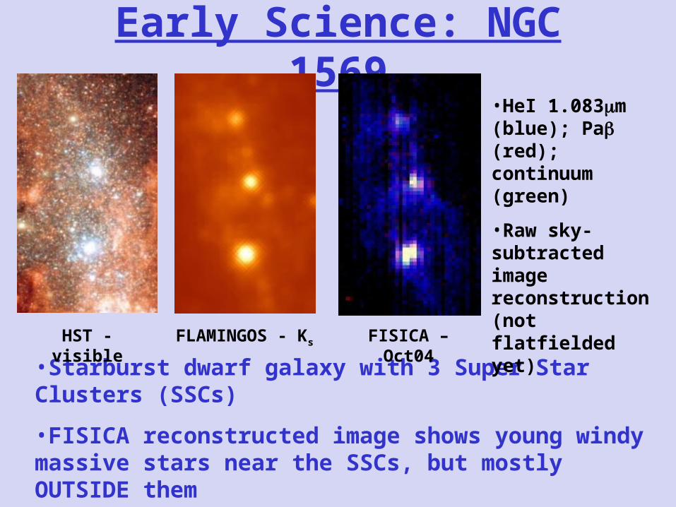
Early Science: NGC 1569
•Starburst dwarf galaxy with 3 Super Star Clusters (SSCs)
•FISICA reconstructed image shows young windy massive stars near the SSCs, but mostly OUTSIDE them
•HeI 1.083m (blue); Pa (red); continuum (green)
•Raw sky-subtracted image reconstruction (not flatfielded yet)
HST - visible FLAMINGOS - Ks FISICA – Oct04

Children of FISICA: FRIDA
•Adaptive Optics-fed IFS/imager for Gran Telescopio Canarias 10.4-meter
•Operates at the diffraction limit of the telescope (resolutions of ~20 mas or ~100 nanoradians

FRIDA/FISICA Similarities
• Fundamental similarities:
• Monolithic approach to mirror arrays
• Similar structural approach – all 6061-T6 aluminum structures
• Same basic team/expertise
• Maximizes utilization of “lessons learned”

FRIDA/FISICA Differences
•Slightly different format for IFU• approach same as FISICA
• overall size/scale of mirrors mechanically very similar
•Geometric aberration requirements tighter (high Strehl):• 2-mirror anastigmat relay approach
• but, direct heritage from FISICA easy to fab/align
•Surface roughness requirements tighter (low scatter):• FISICA dominated by SiO2 inclusions in 6061-T6
• FISICA roughness OK, but not great for FRIDA
• Investigate different material/coating for FRIDA

FRIDA Materials Test Conclusions• Electroless Nickel with Al substrate is a “standard”
diamond-turned material with excellent roughness ( 3nm RMS)
• As expected, this material DOES experience measurable cryo-deformation from bimetallic stresses, seen as edge rollup
• However, the amplitude is small (P-V ~0.07 HeNe)
• All FRIDA mirrors/arrays will/can be slightly oversized to avoid edge effect P-V ~0.016 HeNe
• Thus, Ni/Al mirrors will meet all FRIDA performance requirements

FRIDA IFU Mechanical Design
• Bench-mounted Nasmyth environment (fixed gravity vector)
• Much easier than FISICA (flexure, and thermal too)
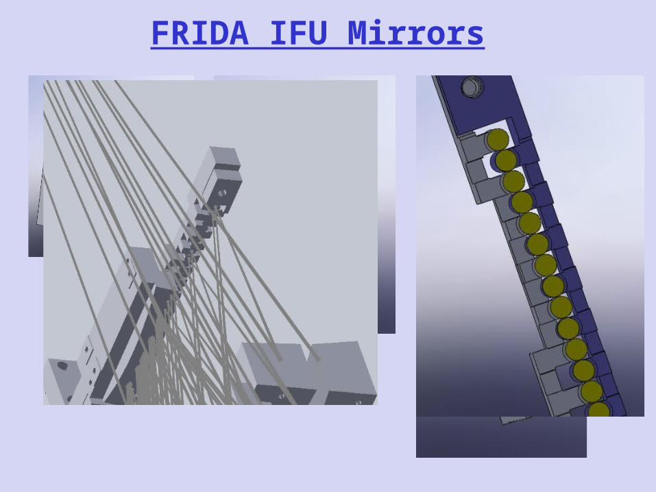
FRIDA IFU Mirrors

Back to HSI:Imaging vs. Spectroscopy
• If you need relatively few spectral channels (i.e. 1, up to ~4-5) and large areal field of view, can use narrowband filters and multiple detectors with dichroics
• But, if you need MANY spectral channels (i.e. 5 to >1000), best use of detector area is probably dispersed spectroscopy

IFS vs. Long-slit Spectroscopy - I
• If your target is large compared to the angular length of a typical slit (i.e. linear FOV ~1000 times the angular resolution element), can use a simple long-slit spectrograph and “push-broom” across the image•But, if your region of interest is large in area but small in linear extent, IFS can cover it more efficiently (by factors up to ~30 or more in scan time)!

IFS vs. Long-slit Spectroscopy - II
• If your target is steady in flux/position/etc. over the 2-D scan time, can use a simple long-slit spectrograph and “push-broom” across the image
•But, if your target is time-variable or moves on the scan timescale, IFS “freezes” the motions/variations and captures a 2D spectrum instantaneously!

IFS vs. Long-slit Spectroscopy - III
• If your detector format/geometry matches your needs for combining FOV with wavelength coverage, then can use a simple long-slit spectrograph and “push-broom” across the image
•But, if your FOV*bandpass needs differ, IFS can allow “optical flexibility” in slit placement/geometry on the detector, and may allow different combinations of FOV and bandpass than available for longslit

Slicers vs. Fibers for IFS•Optical fibers have reasonable transmission at optical wavelengths out to ~1.5µm or so•Most fibers do NOT transmit well at wavelengths >2µm, and the ones that transmit at all are delicate and expensive rare-earth-based fibers•Slicers work well down to wavelengths of ~500nm (well into the optical bandpass), and work very well out to wavelengths of 100µm and beyond•Mirrors are the ultimate “achromatic” optic•Slicers can be VERY robust (solid aluminum construction and/or combine Al mirrors with carbon fiber structures for lighter weight) and VERY compact

Ultra-compact Slicer IFS•New concept developed by SSE at UF for astrophysics (smallsat) and remote sensing (space or UAV) applications•Full size ~10x10x10cm for COMBINED slicer and spectrograph, with mass ~1 kg•Can provide FOV from ~1 sq. arcmin to >10 sq. degree, with resolutions from ~1-arcsec to ~0.1-deg, depending on input optics•Spectral resolutions (R / ()) ranging from ~100 to >20,000•Can operate over wavelength ranges from ~0.5 µm out to >100µm

Conclusions• Image-slicing integral field spectroscopy is a
maturing approach to HIS, particularly relevant for 2D fields of view with high spectral multiplexing requirements
• Monolithic diamond-turned mirror technology produces compact, mechanically robust, no-alignment-needed slicer units
• Existing slicers operate from visible light to far-infrared bandpasses
• Slicers can provide significant advantages over competing technologies (i.e. long-slit “push broom” spectrographs or fiber-fed integral fields)