hydrauli c powerpack
TRANSCRIPT

Hydraulic Powerpack HPP09 HPP13 POR • HPP13 FLEX
HYCON A/S
Juelstrupparken 11 DK-9530 Støvring
Denmark
Tel: +45 9647 5200
Fax: +45 9647 5201 Mail: [email protected]
www.hycon.dk

1
Contents Page 1. Safety Precautions ........................................................................................ 2
2. Filling up Hydraulic Oil................................................................................... 2
3. Technical Data HPP09 ................................................................................... 3
4. Technical Data HPP13 ................................................................................... 4
5. Starting Instructions...................................................................................... 5
6. Service and Maintenance............................................................................... 6
7. Oil Types...................................................................................................... 6
8. Fault Location............................................................................................... 7
9. Mounting of Main Components ...................................................................... 9
10. Mounting of Tank........................................................................................ 14
11. Mounting of Pump ...................................................................................... 15
12. Mounting of Valve Block .............................................................................. 16
13. Replacement of Rubber Coupling ................................................................. 18
14. Replacement of Pump ................................................................................. 19
15. Dismounting of Drive Unit from Frame ......................................................... 21
16. Supplement for HHP13 FLEX........................................................................ 22
17. Tool List ..................................................................................................... 25
18. Spare Parts Lists ......................................................................................... 26

2
1. Safety Precautions
1. Read operating manual for powerpack and engine carefully before using the powerpack.
2. Always use protective earplugs. The powerpack complies with the EU noise limits, but by daily long-lasting operation there is a risk of hearing defects.
3. Always connect hoses before starting. 4. Never add fuel and oil when the engine is running. 5. In case of non-operation or performance of service, always turn off the engine. 6. Never start the engine without side covers. 7. Operation of the powerpack without tool connected and with lever at “ON” may
cause overheating of the system and damage to the powerpack. 8. When lifting the powerpack from a vehicle, we recommend the use of a crane. 9. The pressure relief valve is set at 150 bar from our plant. Never set it higher. 10. Always use filters with by-pass. The use of filters without by-pass may blow the
hydraulic hoses and the filter cover.
2. Filling up Hydraulic Oil
• To fill up with hydraulic oil, loosen the filter cover on top of the power-pack.
• Remove the filter element (see
photo), and fill up with oil. When oil is showing at the bottom of the filter unit, there is enough oil on the powerpack.
• Insert the filter element again, mount the cover and the powerpack is ready for use.
Please note: When connecting new extension hoses, it is necessary to fill up with extra 2 litres of oil. Therefore always top up the powerpack when connecting new extension hoses.

3
3. Technical Data HPP09 Hydraulics The HYCON HPP09 open centre hydraulic powerpack is designed in accordance with the EHTMA category C, which prescribes a minimum performance of 20 l.p.m. at 138 bar. The HYCON powerpack is fully compatible with and sufficient for the common European tools. The powerpack is mounted with a pressure relief valve to avoid a too high pressure. Furthermore, the very efficient air cooling protects the powerpack against over-heating.
Oil flow 20 l.p.m at 3300 r.p.m. Working pressure nominal 120 bar Pressure relief valve Set at 150 bar Pump Gear pump Oil temperature Max. 70° C Hydraulic oil tank capacity Min. 5 litres/max. 7 litres Petrol tank capacity 6 litres Hydraulic system compl. Max. 8 litres Filter system (filter element) 25 Micron with by-pass Engine Honda GX270QXB7 9 HP 4-stroke petrol with oil alert system Petrol - normal or unleaded Engine oil 1.1 litres Guaranteed sound power level LWA 100 dB Sound pressure level 1 m LPA 88 dB Dimensions (LxWxH) 680x560x593 mm Weight, without hydraulic oil 68 kg

4
4. Technical Data HPP13 Hydraulics The HYCON HPP13 open centre hydraulic powerpack is designed in accordance with the EHTMA categories C and D, which prescribe a minimum performance of 20 l.p.m. at 138 bar and 30 l.p.m. at 138 bar, respectively. The HPP13 is available in two versions:
• With POR system (Power On Request) that automatically reduces the engine r.p.m. if the connected tool is not operated. This version is set to 20 or 30 l.p.m. from the factory.
• With manual flow adjustment. This powerpack can be set to 20 to 30 l.p.m. on the front of the powerpack.
The powerpack is mounted with a pressure relief valve to avoid a too high pressure. Furthermore, the very efficient air cooling protects the powerpack against overheating.
Oil flow 20 l.p.m. at 2500 r.p.m. 30 l.p.m. at 3600 r.p.m.
Working pressure nominal 120 bar
Pressure relief valve Set at 150 bar
Pump Gear pump
Oil temperature Max. 70° C
Hydraulic oil tank capacity Min. 5 litres/max. 7 litres
Petrol tank capacity 6.5 litres
Hydraulic system compl. 8 litres
Filter system (filter element) 25 Micron with by-pass
Engine Honda GX390QXB7 13 HP 4-stroke petrol with oil alert system Petrol - normal or unleaded Engine oil 1.1 litres
Guaranteed sound power level LWA 101 dB Sound pressure level 1 m LPA 89 dB
Dimensions (LxWxH) 710x595x605 mm
Weight, without hydraulic oil 81 kg

5
5. Starting Instructions
Please observe the starting instructions on the front of the powerpack. Start: •••• Check engine oil level
• Check hydraulic oil level at sight glass • Connect hoses and tool • Switch fuel tap to “ON” • Activate choke
• Turn ignition switch to “1” • Pull recoil starter • Deactivate choke • Move the lever to “ON” • If the oil is cold, you should let the powerpack run for a couple of
minutes before connecting the tool.
Stop •••• Move the lever to “OFF“
• Turn off the ignition switch • Turn the fuel tap to “OFF”
Powerpack with adjustable flow: The desired oil flow can be set on the front of the powerpack. A marking is engraved in the lever. Turn the lever to the right until the marking is opposite the required flow The pressure relief valve setting will be the same on all flows.

6
6. Service and Maintenance
Service/Maintenance Daily Weekly Yearly
Engine oil Check 1 x replacement
Hydraulic oil Check 1 x replacement
Hydraulic oil filter *) 1 x replacement
Check hoses (tighten up if needed)
Air filter **) 1 x replacement
Fuel filter **) 1 x replacement
*) If the oil does not run down through the filter when removing the cover from the filter housing, the filter is clogged up and must be replaced. Use only filters with by-pass. **) Refer to engine manual for further information.
7. Oil Types
The HYCON powerpack uses standard hydraulic oil, i.e. all types of mineral oil and biodegradable oil, which comply with the following values:
Recommended viscosity 20-40 cSt
Permitted viscosity 15-1000 cSt
Viscosity index Min. 100
Temperature area -20° to +70° C
7
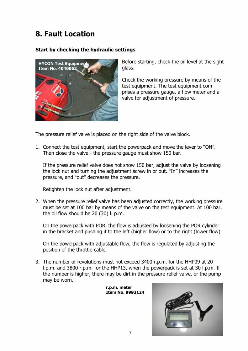
8. Fault Location Start by checking the hydraulic settings
Before starting, check the oil level at the sight glass. Check the working pressure by means of the test equipment. The test equipment com-prises a pressure gauge, a flow meter and a valve for adjustment of pressure.
The pressure relief valve is placed on the right side of the valve block.
1. Connect the test equipment, start the powerpack and move the lever to “ON”. Then close the valve - the pressure gauge must show 150 bar.
If the pressure relief valve does not show 150 bar, adjust the valve by loosening the lock nut and turning the adjustment screw in or out. “In” increases the pressure, and “out” decreases the pressure.
Retighten the lock nut after adjustment.
2. When the pressure relief valve has been adjusted correctly, the working pressure must be set at 100 bar by means of the valve on the test equipment. At 100 bar, the oil flow should be 20 (30) l. p.m.
On the powerpack with POR, the flow is adjusted by loosening the POR cylinder
in the bracket and pushing it to the left (higher flow) or to the right (lower flow).
On the powerpack with adjustable flow, the flow is regulated by adjusting the position of the throttle cable.
3. The number of revolutions must not exceed 3400 r.p.m. for the HHP09 at 20 l.p.m. and 3800 r.p.m. for the HHP13, when the powerpack is set at 30 l.p.m. If the number is higher, there may be dirt in the pressure relief valve, or the pump may be worn.
HYCON Test Equipment Item No. 4040062
r.p.m. meter Item No. 9992124

8
Problem Cause Solution
Pressure relief valve may be clogged up or set incorrectly
Dismount pressure relief valve and clean with compressed air, or correct the setting of the valve
Powerpack does not give the right oil flow, or r.p.m. is too high
Pump is worn Replace pump
The maximum pressure of the powerpack is too high
Wrong adjustment of pressure relief valve
Adjust pressure relief valve to 150 bar (see instructions on page 7)
Leaking shaft seal in pump Replace pump
Oil level too low Add oil
Heavy vibrations because of defective fan blade or defective rubber dampers
Replace defective parts
Hydraulic oil is foaming, and oil is leaking at the air filter on the filter housing
Too much oil in tank Drain off oil from tank
Engine does not start See engine manual
9
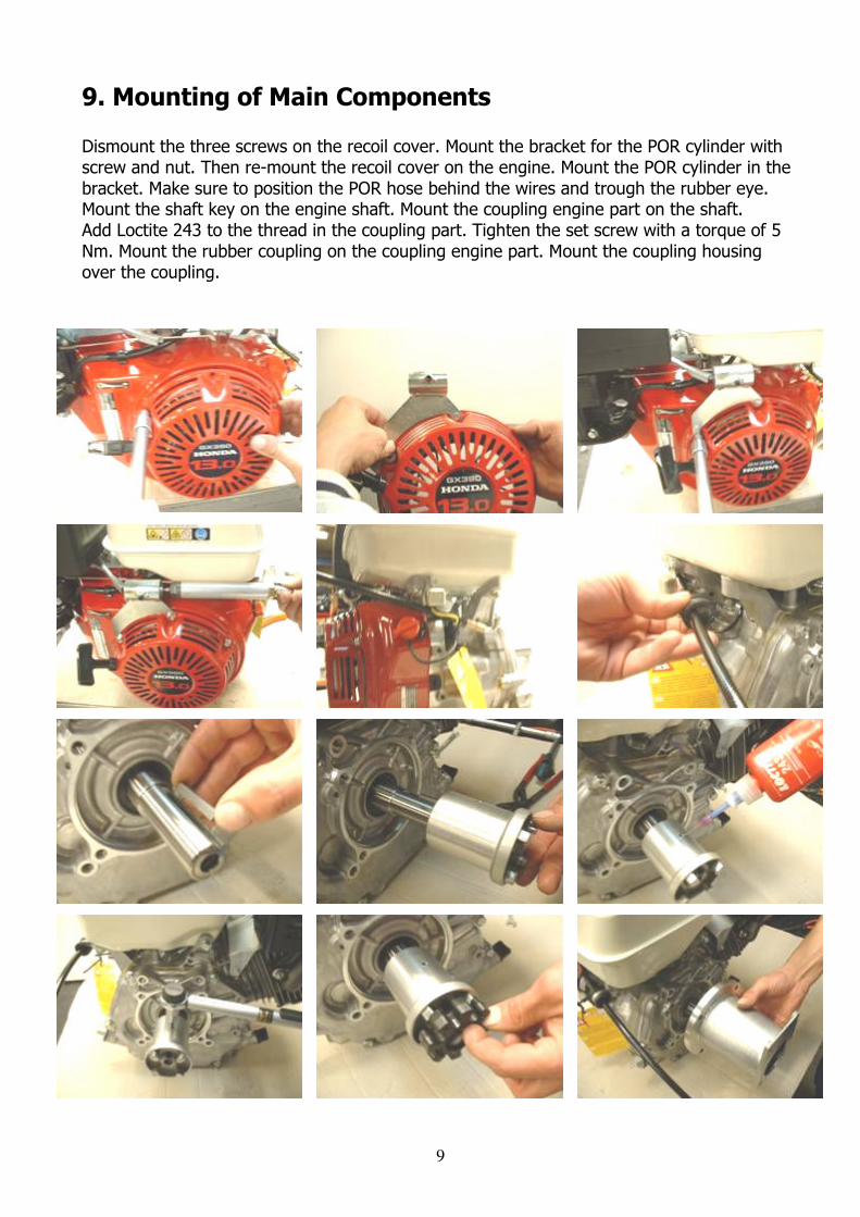
9. Mounting of Main Components Dismount the three screws on the recoil cover. Mount the bracket for the POR cylinder with screw and nut. Then re-mount the recoil cover on the engine. Mount the POR cylinder in the bracket. Make sure to position the POR hose behind the wires and trough the rubber eye. Mount the shaft key on the engine shaft. Mount the coupling engine part on the shaft. Add Loctite 243 to the thread in the coupling part. Tighten the set screw with a torque of 5 Nm. Mount the rubber coupling on the coupling engine part. Mount the coupling housing over the coupling.

10
Add Loctite 243 to the four threads, and tighten the screws with a torque of 20 Nm. Mount the pump with the coupling part into the coupling housing. It is important to fit the washer between pump and coupling housing perfectly into the frame on the coupling housing. Make sure that the coupling part on the pump fits into the rubber coupling (if necessary, turn the pump shaft until the parts fit). Add Loctite 243 to the four threads on the coupling housing. Mount the cooler over the pump, and mount the four long screws through the cooler and the pump into the thread on the coupling housing. Tighten the four screws with a torque of 15 Nm. Place a spring washer on the shaft with the curve towards the cooler (see drawing). Place the shaft key in the keyway on the shaft.

11
Mount the fan on the shaft, and place the spring washer on the shaft with the curve turned outwards. Mount the nut and tighten with a torque of 40 Nm. Add Loctite 243 to the two threads on the frame, and mount the bolts. Place the tank in the frame. Mount the tank with four screws, washers and lock nuts. Mount the rubber dampers on the frame. Screw in the screws with washers from below. Mount the valve block on the frame. Add Loctite 243 to the four threads.

12
Tighten the four screws. Mount the bypass hose on the filter housing. Mount the other end of the bypass hose on the valve block. Lift the drive unit into the frame, and place the drive unit on the two rubber dampers. Tighten the four screws with washers (at one side it is easier to tighten the screws after dismounting the wheel). Add Loctite 638 to the thread on the supporting leg, and screw together the supporting leg and the rubber damper. Mount the rubber damper on the frame with a screw and washer from below. Mount the suction hose on the tank. Mount the return hose on the filter housing. Mount the hydraulic hose from the pump on the left fitting on the valve block.
13
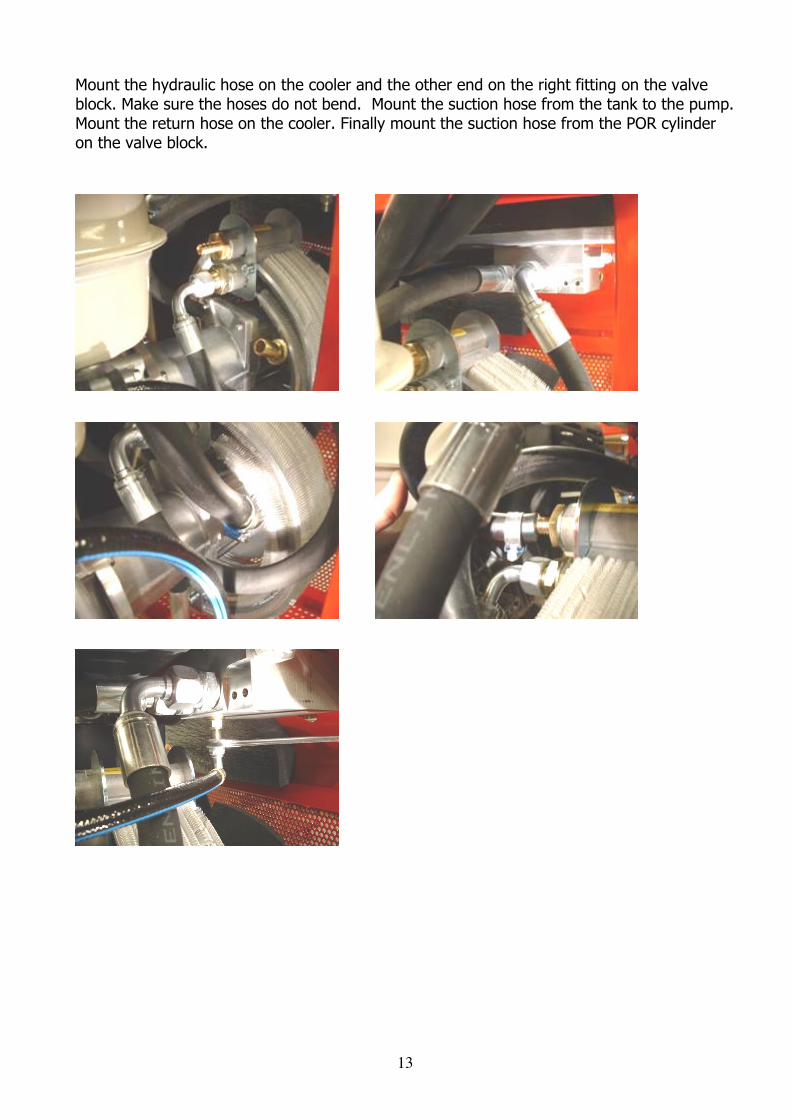
Mount the hydraulic hose on the cooler and the other end on the right fitting on the valve block. Make sure the hoses do not bend. Mount the suction hose from the tank to the pump. Mount the return hose on the cooler. Finally mount the suction hose from the POR cylinder on the valve block.

14
10. Mounting of Tank Grease the seal on the sight glass with silicone. Carefully mount the sight glass on the tank. Tighten carefully. Mount the hose on the filter housing and tighten the hose clip with an end cutter. Mount the filter housing into the tank (remember to mount the seal between tank and filter housing). Add Loctite 243 to the thread, and tighten the screws carefully. Add Loctite 542 and mount the hose fitting for the return line. Mount the hose fitting for the suction hose. Always remember the seal ring between hose fitting and filter housing.

15
11. Mounting of Pump Start by mounting the angle nipple at the right side of the pump. Mount the centering washer and the coupling part on the pump shaft. Tighten the nut with a torque of 20 Nm. Mount the hydraulic hose with banjo at the left side of the pump. Adjust the angle nipple and the hydraulic hose till they are at the same angle to each other as shown on the photo.

16
12. Mounting of Valve Block Re. HHP13 FLEX, please refer to section 16 Add Loctite 542 to the two threads at the left, and tighten the pipe plugs firmly. Add Loctite 542 to the thread at the side of the valve block, and tighten the pipe plug. Mount two roll pins on the valve block with the groove turned upwards and a roll pin on the spool. Mount the retaining ring and the O-ring on the spool. Mount the O-ring in the hole in the valve block. Mount the check valve with the holes turned upwards. Screw in the check valve completely. Add Loctite 542 to the upper part of the thread, and mount the hose fitting. Mount the two seal rings and fittings on the valve block.
17
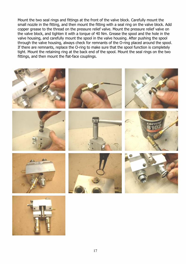
Mount the two seal rings and fittings at the front of the valve block. Carefully mount the small nozzle in the fitting, and then mount the fitting with a seal ring on the valve block. Add copper grease to the thread on the pressure relief valve. Mount the pressure relief valve on the valve block, and tighten it with a torque of 40 Nm. Grease the spool and the hole in the valve housing, and carefully mount the spool in the valve housing. After pushing the spool through the valve housing, always check for remnants of the O-ring placed around the spool. If there are remnants, replace the O-ring to make sure that the spool function is completely tight. Mount the retaining ring at the back end of the spool. Mount the seal rings on the two fittings, and then mount the flat-face couplings.

18
13. Replacement of Rubber Coupling Unscrew the four screws from the coupling housing to the engine. Dismount the POR hose from the valve housing. Turn the coupling housing, the pump and the cooler out to the right. The rubber coupling can now easily be replaced at the opposite side of the powerpack. Turn coupling housing, pump and cooler back into position. To make sure that the rubber coupling is in the right position, you can turn the fan until the coupling fits correctly. Mount the four screws from the coupling housing to the engine, and tighten the screws with a torque of 20 Nm. Mount the POR hose on the valve housing.
19
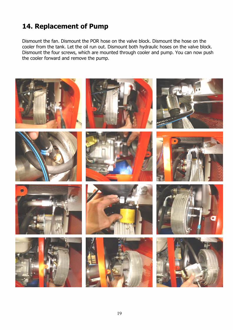
14. Replacement of Pump Dismount the fan. Dismount the POR hose on the valve block. Dismount the hose on the cooler from the tank. Let the oil run out. Dismount both hydraulic hoses on the valve block. Dismount the four screws, which are mounted through cooler and pump. You can now push the cooler forward and remove the pump.

20
Mount the pump in the coupling housing. It is important that the coupling part on the pump is fitted correctly in the rubber coupling. It is also important to fit the centering washer between pump and coupling housing completely into the frame on the coupling housing. Mount the cooler with the four screws through cooler and pump, and tighten them with a torque of 15 Nm. Mount the fan, and tighten the nut with a torque of 40 Nm. Mount again the hydraulic hoses on the valve block. Mount the hose from the tank on the pump. Mount the POR hose on the valve block.

21
15. Dismounting of Drive Unit from Frame Dismount the four screws on the frame holding the valve block. Dismount the two hoses on the filter housing. Dismount the hose on the pump. Dismount the four screws under the engine. Dismount the supporting leg under the frame. The entire drive unit can now be removed, and it is easy to do major repairs.
22
16. Supplement for HPP13 FLEX Mounting of special parts for HPP13 FLEX
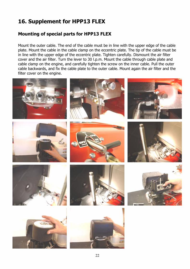
Mount the outer cable. The end of the cable must be in line with the upper edge of the cable plate. Mount the cable in the cable clamp on the eccentric plate. The tip of the cable must be in line with the upper edge of the eccentric plate. Tighten carefully. Dismount the air filter cover and the air filter. Turn the lever to 30 l.p.m. Mount the cable through cable plate and cable clamp on the engine, and carefully tighten the screw on the inner cable. Pull the outer cable backwards, and fix the cable plate to the outer cable. Mount again the air filter and the filter cover on the engine.

23
Mounting of special parts on valve block for HPP13 FLEX Add Loctite 542 to the two threads to the left, and tighten the pipe plugs firmly. Add Loctite 542 to the thread at the side of the valve block, and tighten the pipe plug. Mount two roll pins on the valve block with the groove turned upwards and a roll pin on the spool. Mount the retaining ring and the O-ring on the spool. Mount the O-ring in the hole in the valve block. Mount the check valve with the holes turned upwards. Screw in the check valve completely. Add Loctite 542 to the upper part of the thread, and mount the hose fitting. Mount the two seal rings and fittings on the valve block.

24
Add Loctite 243 to the two threads on the valve block, and mount the cable plate with two screws. Mount the cable clamp on the cable plate. Mount the screw with hole through the eccentric plate.
25
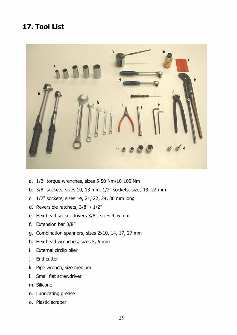
17. Tool List
a
b
c
d
e
f
g h i
j
k
l
m n
o
a. 1/2” torque wrenches, sizes 5-50 Nm/10-100 Nm
b. 3/8” sockets, sizes 10, 13 mm, 1/2" sockets, sizes 19, 22 mm
c. 1/2" sockets, sizes 14, 21, 22, 24, 30 mm long
d. Reversible ratchets, 3/8” / 1/2”
e. Hex head socket drivers 3/8”, sizes 4, 6 mm
f. Extension bar 3/8”
g. Combination spanners, sizes 2x10, 14, 17, 27 mm
h. Hex head wrenches, sizes 5, 6 mm
i. External circlip plier
j. End cutter
k. Pipe wrench, size medium
l. Small flat screwdriver
m. Silicone
n. Lubricating grease
o. Plastic scraper