hybrid wing body aircraft acoustic test preparations and ...hybrid wing body aircraft acoustic test...
TRANSCRIPT

28th AIAA Aerodynamic Measurement Technology, AIAA-2013-xxxx Ground Testing, and Flight Testing Conference, 24 - 27 June 2013, San Diego, California
___________________________________________________________________________________________________
† Research Aerospace Engineer, Aeroacoustics Branch, MS 461, Member AIAA ‡ Senior Research Scientist, Aeroacoustics Branch, MS 461, Fellow AIAA * Senior Research Aerospace Engineer, Aeroacoustics Branch, MS 461, Senior Member AIAA Facility Systems Engineer, Subsonic Transonic Testing Branch, MS 289, Member AIAA Research Student Trainee, Aeroacoustics Branch, MS 461, Student Member AIAA
Research Aerospace Engineer, Advanced Sensing and Optical Measurement Branch, MS 493, Member AIAA Senior Scientist, Advanced Sensing and Optical Measurement Branch, MS 493, Member AIAA
£ Engineering Technician, Advanced Sensing and Optical Measurement Branch, MS 493, Member AIAA + Engineering Technician, MS 461 § Test Engineer, MS 289
Senior Engineer, MS 461
1 American Institute of Aeronautics and Astronautics
Hybrid Wing Body Aircraft Acoustic Test Preparations and Facility Upgrades
Stephanie L. Heath†, Thomas Brooks‡, Florence Hutcheson*, Michael J. Doty*, Henry H. Haskin†, Taylor Spalt , Christopher Bahr†, Casey Burley*, Scott Bartram£, William Humphreys , Charles B. Lunsford , Thomas Popernack
and Scott Colbert
NASA Langley Research Center, Hampton, VA, 23681
Danny Hoad , Lawrence Becker and Daniel Stead
Northrop Grumman
Dennis Kuchta+ and Les Yeh§ Jacobs Sverdrup ROME, NASA Langley Research Center, Hampton, VA, 23681
A hybrid wing body transport aircraft model was tested in NASA Langley’s 14 by 22Foot Subsonic Tunnel to evaluate proposed “low noise” technology. The experiment was set up to evaluate the community noise impact of the hybrid wing body design, as well as study the noise components of propulsion-airframe noise and shielding. A high fidelity 5.8-percent scale model, including landing gear, cruise and drooped wing leading edges, trailing edge elevons, vertical tail options, and engine noise simulators, was built to test both aerodynamic and acoustic configurations. The aerodynamic test data were used to establish appropriate flight conditions for the acoustic test.
To accomplish the acoustic portion of this test, two major upgrades were required of NASA Langley’s 14 by 22 Foot Subsonic Tunnel; first, a fuel delivery system to provide realistic gas temperatures to the jet engine simulators; and second, a traversing microphone array and side towers to measure full spectral and directivity noise characteristics.
The results of this test provide benchmark hybrid wing body aircraft and noise shielding data to assist in achieving NASA’s 2020 noise emission goals.
I. Introduction
To achieve the next generation of aircraft noise reductions, the aircraft noise research community must search beyond traditional airframe and engine noise sources. When the propulsion system and airframe are considered as a unit, additional acoustic sources can be created or significantly altered. A complete high fidelity wind-tunnel model of the HWB system was built to develop, test and understand new aircraft propulsion aeroacoustic (PAA) technologies such as flows through and around the engines and airframe, shielding effects, and diffraction around aircraft edges.
The Hybrid Wing Body (HWB) aircraft configuration with the installation of the engines on the upper surface of the airframe and highly integrated fuselage and wings should yield quieter aircraft characteristics. To obtain accurate acoustic data on this unconventional HWB aircraft, it was important to have wind tunnel test conditions as close to real flight conditions as possible to capture all propulsion aircraft acoustic influences. The current test involves not
https://ntrs.nasa.gov/search.jsp?R=20140000463 2020-03-25T13:37:01+00:00Z

2 American Institute of Aeronautics and Astronautics
just shielding of the engine noise but also understanding and rearranging the noise sources to take advantage of shielding. Two types of engine noise simulators were used to test the effectiveness of engine shielding benefits: a broadband noise simulator to represent turbomachinery noise and a compact hot jet engine simulator to represent the jet noise.
This test is uniquely designed to demonstrate the achievability of the Agency goals by answering the question, “How much noise reduction can be achieved with a HWB concept”? The HWB assessment, anticipated in September 2013, will evaluate the progress toward achieving NASA’s noise emission goals of 42 Effective Perceived Noise Levels in decibels (EPNL dB) cumulative noise below the Federal Aviation Administration (FAA) Federal Aviation Regulations (FAR) 36 Stage 4 certification level1.
The planning of these tests began in 2008 under NASA’s Environmentally Responsible Aviation (ERA) project and was first presented to the aeroacoustic community in 20112. The HWB aircraft was designed as a cargo plane with a 6000 nautical mile mission and a maximum payload of 103,000 pounds3. It was based on a new integrated planform with conventional state of the art dual engines. The research efforts were broken into two stages: an aerodynamic wind tunnel test in July 20114 and an aeroacoustic test from September 2012 through January 2013. Both tests were conducted in Langley Research Center’s 14 by 22 Foot Subsonic Tunnel. The 14x22 Tunnel was advantageous for the HWB acoustic test because of its size: To obtain full scale high frequency acoustics of interest, the corresponding wind tunnel model wing span was almost thirteen (13) feet. In addition, with some modifications to the tunnel, it was possible to invert the HWB model and sweep an acoustic array over a large range of directivity angles.
The Hybrid Wing Body (HWB) aircraft concept for this study was developed under a NASA Research Announcement (NRA) with Boeing. The Boeing team included the Massachusetts Institute of Technology (MIT), the University of California at Irvine (UCI), and the United Technologies Research Center to provide noise prediction assessments and test design support for the development of the HWB vehicle. As part of the noise assessment effort new noise shielding methods for installed turbomachinery and jet noise were developed with the intent of eventual integration into the Aircraft Noise Prediction Program (ANOPP5). ANOPP26 is being expanded to incorporate prediction capabilities for advanced unconventional vehicle designs such as the HWB.
The shielding results of the HWB test will be used to 1) determine the spectral levels and noise directivity of the HWB airframe and engine simulator components, 2) characterize noise shielding benefits of the HWB fuselage, and 3) provide a benchmark acoustic database of isolated and shielded components for development/validation of noise prediction capabilities including those of ANOPP and ANOPP2.
The purpose of this paper is two-fold. First, to document the Hybrid Wing Body (HWB) activities required in the investigation; and second, to inform the acoustic community of the new acoustic testing capabilities in NASA Langley Research Center’s 14 by 22 Foot Subsonic Tunnel.
II. Background and History
The aircraft noise research community has significantly reduced aircraft noise over the past five decades through the development of advanced bypass ratio fans, advanced jet nozzles, and airframe noise reduction technologies. Figure 1 maps the historical reduction in commercial aircraft noise up to the present. Large jumps in noise reduction have been attributed to advancing engine technologies. As advances in engine noise technology with acceptable performance become more challenging, noise reduction becomes increasingly more difficult and it becomes necessary to look at other technologies to achieve further noise reduction.
The National Aeronautics Research and Development Plan7 designates “N+1”, “N+2” and “N+3” successive notional aircraft generations to anchor the environmental goals. A HWB design with engines mounted on the upper surface for shielding benefits has been proposed as a means of meeting the N+2 noise goals. It is anticipated that only half of the noise reduction assessed against the N+2 goals will be attributable to engine technologies; thus to achieve further noise reduction, the community must investigate new aircraft configurations including shielding. In order to correlate NASA’s cumulative noise reduction goals to an average noise reduction, as seen in Figure 1, the Environmentally Responsible Aviation (ERA) N+2 project goal of 42 EPNL dB cumulative reduction at the FAA’s three certification points with an average reduction of 14 EPNL dB relative to stage 4.

3 American Institute of Aeronautics and Astronautics
Figure 1. Normalized Average Historical Progress in Aircraft Noise Reduction 8, 9, 10. The noise values are normalized to 100,000 lb thrust. Significant noise reduction has been accompanied by engine technologies in the past. Note: Average EPLN values reflect 1/3 of the cumulative noise levels which include take-off, sideline/cutback and approach certification values.
Prior to undertaking this test, a pretest system noise assessment11 of the hybrid wing body with state-of-the-art engines was performed using NASA’s best available aircraft models, engine models, and systems level code (ANOPP) to determine the probability of success in achieving NASA’s N+2 acoustic goal. Where ANOPP prediction codes were inadequate, an experimental database containing suppression factors for key noise sources and interaction effects was directly input into the ANOPP noise assessment. In addition to the shielding database two codes, the Fast Scattering Code 12 (FSC) and the Diffraction Integral Method Code 13 (DIM), were used to predict noise scattering effects for the broadband fan noise, tonal fan noise and jet noise. Since the completion of the assessment, the diffraction code has been enhanced to account for more general reflections and edge effects, which for the HWB range from the sharp trailing edge to a more rounded blunt leading edge.
A post-test HWB assessment will demonstrate the viability of the HWB aircraft to achieve NASA’s goals. But just as importantly, the results of this test will be used to update the shielding databases compiled over the last decade from the works of Clark and Gerhold14, Hill15,16, Reimann and Tinetti17, and most recently by Czech, Thomas, and Elkoby18, and to validate the scattering and diffraction codes.
III. HWB Model
The HWB model is 5.8% of full scale which easily allows acoustic measurements over the full scale equivalent range of about 230 Hz to 4.1 kHz (4 to 70 kHz model scale). The HWB low-speed wind tunnel model represents Boeing’s Quiet R1 configuration aircraft, and is designated as N2A-EXTE. The HWB aircraft consists of wings which are highly integrated with the central fuselage and of accurately scaled details for airframe noise studies. The model was built by MicroCraft, Inc. under contract to Boeing and is illustrated in the expanded view presented in Figure 2. It measures 8.58 feet long with a span of 12.35 feet.
-25
-15
-5
5
15
25
35
1950 1960 1970 1980 1990 2000 2010 2020 2030 2040
Ave
rage
Noi
se L
evel
Rel
ativ
e to
Sta
ge 4
(EPN
dB)
Year of Certification
Turbojet and Turbofans
First GenerationTurbofan (LBPR)
Second GenerationTurbofan (HBPR)
AST/QAT Ultra HBPRGeared Turbofan
N+1 Goal
N+2 Goal
N+3 Goal
Stage 2
Stage 3
Stage 4

4 American Institute of Aeronautics and Astronautics
The model is modular with components and control surfaces that may be deflected to match specific flight conditions. The components include drooped and cruise leading edges, trailing edge elevons, vertical tails, landing gear, and flow through nacelles (which are replaced during the acoustic testing with turbomachinery and jet noise simulators).
Figure 2. General HWB Model Arrangement.
The HWB wing is swept and has twist at the wingtip. The model reference area is 33.50 ft2, with a reference chord of 60.55 inches and a model moment reference center at 54 percent of the fuselage length aft of the model nose. The model has removable, hinged leading edge shapes, one for cruise and one for the low-speed “drooped” leading edge. The drooped leading edge is deflected 20 down at approximately 30 % span and transitions to a deflection of 30 between 40 and 45 % span and then remains at 30 deflection for the remainder of the outboard portion of the span.
The HWB model also supports various vertical tail configurations. These configurations include two vertical tail geometries (long span/short chords and short span/long chords) and two cant angles (10 and 30 ) for each tail geometry. The vertical tails can be located at either a forward or rear longitudinal position, and also support three rudder deflection angles. Referring to Figure 2, there are eleven independently deflectable elevons along the trailing edge of the vehicle. A center elevon (E1) positioned between the two vertical tails, and 5 elevons extending across the trailing edge of each wing. Each elevon can be set at -40°, -10°, 0°, +10°, or +40° deflection angles. The thickness of the model trailing edges is approximately 0.009” which accurately represents a 5.8% scaling of the full size geometry.
Removable high-fidelity landing gears include left and right main gears and a nose gear. All gear components, hydraulic lines, actuators, side braces, brake system and tire treads are scaled. Gear wells and partially covered wheel wells and gear doors are also scaled. In addition to the landing gears, flow-through nacelles with pylons can be mounted on the fuselage upper surface at three different longitudinal stations.
The baseline model configuration for the HWB test consisted of the drooped leading edge, the nacelles (engine noise simulators) in the mid location, the longer span vertical tails mounted with a 10° cant angle in the aft location, all elevons and rudders undeflected, the landing gear off, and the landing gear wells closed.
(Landing gear, gear doors and cavities also included)
Translational nacelles and pylon
Next Generation Bomber
Fixed Wing
Drooped LE
Fixed LE
Nominal Location 1.6 FPR Engines
Removable Aft Body
Removable Elevons, E1-E6 Movable Fins and Rudders
E2
E1
E3 E4 E6 E5

The HWsensing deelectronicarow of 45 inside the sensors onCompact Jmodel wasused for tutwo were m
EngineCompact Jthe broadbConfigurabOnly the CResearch C
BroadA.Each B
interchangformed bythrough 0.aerodynameither inletdistributed
F
Removedge senacelle
Kulsen
WB model waevices. Two hally scanned prpressure taps ostarboard flow
n the fuselage uJet Engine Nos equipped withuning of micropmounted in the
e noise simulaJet Engine Simband componeble Fan Noise CJES and BENCenter19 to obta
dband EngineBENS consisteable rings of
y four coplanar5” lines. Each
mically shaped)t or outlet nois
d around the na
igure 3. Cross
vable leading ection of the
f
lite pressure nsors location
America
as instrumentedhundred and fressure moduleon the body, 6w through nacupper surface, ise Simulatorsh 6 small compphone array prwings.
ators were desmulator (CJES)ent of turbomSimulator (UC
NS were used ain additional t
Noise Simulated of an in
f impinging airr tubes arrang
h nacelle is app) inlet and outse radiation. Eacelle inlet and
s Section of Br
3 identi
fairing
an Institute of
d with pressureforty eight (24es: 3 rows of 464 pressure tapcelle, and twojust aft of the
s were in use. pression speakerocessing. Four
IV. E
signed and de was designedachinery noise
CFANS) for thin the HWB
tonal data requ
ator (BENS) nternally openr jets with isoled in a crucifproximately 6”tlet caps (showach BENS wa10 sensors dis
roadband Eng
ical plenums
Pylon (
5 f Aeronautics
e taps, tempera48) surface st45 pressure tapps on the right located in thnacelles to moIn addition to
er drivers. Ther drivers were p
Engine Simul
eveloped to red for jet noise, e, and a thirde simulation oaeroacoustics
uired to comple
n nacelle withlated plenums form planform” in diameter awn in Figure 4as also instrumtributed around
gine Noise Sim
3 impinnacelle
Impin
(3) Kulitsenso
and Astronau
ature sensors, tatic pressuresps located on thand wing and
he balance cavonitor the fuseo pressure ande drivers were epositioned in t
lators
ealistically moa Broadband
d engine noisef the tonal comtest. The UCF
etely assess HW
h a represen(shown in Fig. Air was supand 12” long. 4). These caps
mented with 10 d the core struc
mulator.
Core struc
nging jet rings e (order interch
inging jet air su
te pressure ors location
utics
and typical AOs were connecthe left hand wd 4 internal sta
vity. There weelage temperatud temperature embedded intothe center porti
odel the enginFan Engine Sie simulator camponents of tuFANS was tesWB shielding e
ntative core sgure 3). Each jpplied at 120 p
Each nacelle s were used se
unsteady surfcture near the o
cture
slide into the hangeable).
upplies
OA (angle of acted to the onwing of the moatic pressure oere four tempeure when the Ninstrumentatio
o the model andion of the mod
ne noise sourcimulator (BENalled the Ultr
urbomachinery ted at NASA
effects.
structure, and jet noise sourcpsig to each phad removabl
eparately to simface pressure soutlet.
attack) nboard odel, 1 orifices erature NASA on, the d were del and
ces. A NS) for rasonic
noise. Glenn
three ce was plenum e (and mulate sensors

A serieas the impto be used the paramedevelopme
Testingestablish sto record tas to contro
es of preliminaringing jets conto analyze the
eters and signent of the HWBg of the BENSome of the BEhe signals fromol the instrume
Figu
BE
America
Figure 4.
ry tests were pnfiguration, aire BENS acousnals that needeB test matrix. S in a shieldedENS operating m the BENS uentation travers
re 5. BENS Pre
ENS inlet and o
an Institute of
BENS Assemb
erformed on thr pressure and stic data; (3) deed to be mon
d configurationrequirements a
unsteady surfacse system.
eliminary Shield
outlet caps
6 f Aeronautics
bly on the Acous
he BENS to: (1transitional flo
etermine the Bitored during
n is shown in and to exercise
ce pressure sen
ding Test in sep
and Astronau
stic Model Supp
1) establish theow requiremen
BENS noise radthe HWB aer
Figure 5. Thie the data acqu
nsors and from
parate Semi-An
Attachmen
utics
port.
e BENS operatints); (2) establdiation charactroacoustic test
s particular teuisition system
m the phased ac
nechoic Facility.
nt arms
ing parametersish the methodteristics; (4) idt; and (5) guid
st was performm that was devecoustic array, a
.
s (such dology dentify de the
med to eloped as well

UltrasB.The Ul
Research Cof a high-modes (suelectrostatiand 40 kHmeasuremein conjuncturbomach
CompC.The jet
flow and oflow. The a
The co(AFRL)20. burned in aA schematcavity at 6of the fuel
Figure 6. C
The intchrome par
The CJand ancillaengine, bepressure raNumerical scale) and for the cyc
UlCo
Core
sonic Configultrasonic ConfiCenter in the Abypass turbofa
uch as those pic actuators insHz. The UCFents from the Uction with the
hinery noise.
pact Jet Engint noise source outer fan flow.air and fuel floombustor conc
The combustoan annular comtic of the jet en locations. Swand air. This d
Compact Jet En
ternal hot gas prts were used f
JES nozzles to ary systems (suetween BPR-5 atio-NPR, and Propulsion Syconsistent wit
cle points were
ltra Compact ombustor Asse
Pro
Air Inlet
America
rable Fan Noiigurable Fan N
Acoustical Testan engine thatproduced by tside a dual annANS was use
UCFANS in she BENS data
ne Sumilator (Cis produced by A fuel system
ows for each encept for CJES or uses a uniq
mbustion chamngine simulator
wirl air is injectdesign allows a
ngine Simulator
path componenfor both the linbe used during
uch as valve paand BPR-15.nozzle temper
ystem Simulatith each CJES ne established fo
embly
opane Inlet
an Institute of
ise Simulator Noise Simulatoting Laboratoryt can generatethe engine’s tunulus within theed to simulatehielded and uns
acquired in
CJES) y two dual stre
m, to be describngine simulator
was modeledque compact a
mber followed br is shown beloted on either sia shorter combu
r Schematic.
nts include a coers and the corg the HWB tesallets) were de Engine cyclerature ratio-NTon (NPSS) ananozzle design 2
or relevant HW
Low Noise FConditions
Fan Air I
7 f Aeronautics
(UCFANS) or (UCFANS)19
y (ATL). The tonal signatuurbomachinerye fan duct and e the radiationshielded configthe HWB aer
eam jet enginebed later, suppr are independed after researcannular propanby a core vane ow in Figure 6ide of the fuel ustor length an
ombustor linerre vanes duringst were sized toesigned to accoes and correspTR) were predialysis for a byp21, 22. The given
WB flight speed
Flow
Inlet
and Astronau
9 was designedUCFANS is a
ures using artify) are generatcan drive modn of some of gurations wereroacoustics te
e simulators coplies gaseous pently controllech done at thene burner to he
assembly whic6. The combustjets angled at
nd a more effic
r and a core vag the test to mao simulate a BPommodate a brponding paramicted based uppass nozzle exin HWB flight d, altitude, and
BPR-10 Charging Station
Fan Nozz
utics
d, built and tesa 5.8% rapid prficial sources ted by an arradally phased tonf the HWB ene obtained15. Thst to assess s
onsisting of anpropane to a cod by two valvee Air Force Reat the core flch helps to strator injects fuel45 to radial a
cient combustor
ane assembly. Laximize durabiPR of 10 enginroader range of
meters (mach non engine statit area of 4470 profile and th
d throttle settin
zle
Core Nozzle
Plu
sted at NASA rototype scale (no flow). Sp
ay of 36 widene signals betwngine modes. his data is to bshielding effec
n interior heateombustor in the pallets. Research Labolow. The propaighten out thel radially into aand promotes mr.
Laser sintered lity. ne, however, thf bypass rationumber-M# , nte tables provid
in2 (15.12 in2
e NPSS enginengs. The CJES
e
ug
Glenn model inning e-band ween 7
Noise e used cts on
ed core he core
oratory pane is e flow. a swirl mixing
cobalt
he fuel (BPR) nozzle ded by model e deck
S units,
propane syair supply
Table 1. Su
Bypass Ra
BPR-5
BPR-15
The CJ
baseline stThe lo
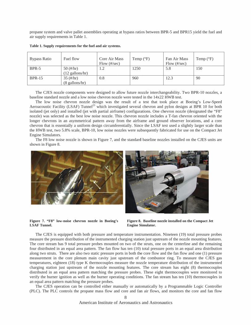
Aeroacousisolated (jenozzle) walonger chechevron ththe HWB tEngine Sim
The F8shown in F
Figure 7. “LSAF Tunn
The CJ
measure thThe core sfour distribalong two measuremetemperaturcharging sdistributedverify the an equal ar
The CJ(PLC). Th
ystem and valvrequirements i
upply requireme
atio Fuel
50 (#(12 g35 (#(8 ga
JES nozzle comandard nozzle
ow noise chevstic Facility (Let only) and inas selected as tevrons in an ahat is essentialltest, two 5.8% mulators. 8 low noise nozFigure 8.
“F8” low-noisenel.
JES is equippehe pressure diststream has 9 tobuted in an equstruts. There aent in the corres, eighteen (1station just upd in an equal aburner ignitionrea pattern matJES operation e PLC control
America
e pallet assembn Table 1.
ents for the fuel
l flow
#/hr) gallons/hr) #/hr) allons/hr)
mponents wereand a low nois
vron nozzle dSAF) Tunnel2
nstalled (jet witthe best low nasymmetrical ply a uniform descale, BPR-10
zzle is shown i
e chevron nozz
ed with both prtribution of theotal pressure prual area patternare also two stare plenum mai18) type K thepstream of thearea pattern mn as well as thtching the prescan be contro
ls the propane
an Institute of
blies operating
l and air system
Core Air MFlow (#/sec1.2
0.8
e designed to ase chevron nozdesign was th
3 which investth partial airfraoise nozzle. Thpattern away fesign circumfe0, low noise no
in Figure 7, an
zle in Boeing’s
ressure and teme instrumented robes mountedn. The fan flowatic pressure pin cavity just
ermocouples me nozzle moun
matching the prhe burner operasure probes.
olled either mamass flow an
8 f Aeronautics
g at bypass rati
ms.
Mass c)
Temp
1250
960
allow future nozzle were testede result of a tigated severalame) configurahis chevron nofrom the airfraerentially. Sincozzles were sub
nd the standard
s Figure 8.Engine S
mperature instrcharging statio
d on two of thew has ten (10) orts in both theupstream of t
measure the noznting features. ressure probesating condition
anually or autond core and fan
and Astronau
ios between BP
p (°F)
ozzle interchand in the 14x22
test that tool chevron and ations. One chozzle includes ame and grounce the LSAF tebsequently fab
d baseline nozz
. Baseline nozzSimulator.
rumentation. Non just upstreae struts, one ontotal pressure
e core flow andthe combustorzzle temperatu
The core str. These eight
ns. The fan stre
omatically by n air flows, an
utics
PR-5 and BPR
Fan Air MassFlow (#/sec) 5.8
12.3
ngeability. TwoHWB test.
ok place at Bpylon designs
hevron nozzle (a T-fan chevr
nd observer loest used a slighbricated for use
zles installed o
zle installed on t
Nineteen (19) tam of the nozzln the centerlin ports in an eqd the fan flow r ring. To me
ure distributionream has eighthermocoupleseam has ten (1
a Programmabnd monitors th
R15 yield the fu
s Temp (°F
150
90
o BPR-10 noz
Boeing’s Low-at BPR 10 fo
(designated theron oriented wocations, and htly larger scale on the Comp
n the CJES un
the Compact Je
total pressure ple mounting feane and the remqual area distriand one (1) pr
easure the CJEn of the instrumt (8) thermocs were monito10) thermocoup
ble Logic Conhe core and fan
uel and
F)
zzles, a
-Speed or both e “F8” ith the a core le than act Jet
nits are
et
probes atures.
maining ibution ressure ES gas mented ouples
ored to ples in
ntroller n flow

9 American Institute of Aeronautics and Astronautics
stream temperatures and pressures. Once the mass flows were set to the correct range, fine control adjustments were based on nozzle temperature ratios (NTRs) and nozzle pressure ratios (NPRs).
Numerous CJES risk reduction studies were completed in preparation for the HWB acoustic test. A brief overview of each study and an explanation of their relevance to the larger HWB test are given below.
Operational and preliminary acoustic testing took place in NASA’s Low Speed Aeroacoustic Wind Tunnel (LSAWT) which was modified to accommodate the CJES fuel valve pallet. Establishing consistent operation of each of the CJES units was a primary objective. This objective was achieved in the LSAWT after several modifications to the combustor and core flow conditioners24 (see Figure 10).
One challenge in modeling scaled jet noise is that internal rig noise tends to contaminate the jet noise. Flow conditioner studies by Doty and Haskin25 investigated the acoustic properties of numerous flow conditioner configurations for optimal rig noise reduction in anticipation of this issue. Flow conditioners and screens were evaluated to help minimize unwanted tones and broadband noise.
In addition to understanding each CJES unit individually, relevant twin jet acoustic and flow field effects were investigated by Doty26 in the LSAWT using the linear microphone array and the Jet Noise Directional Array (JEDA27). Recommendations for the CJES test matrix based on twin jet results were used as input for the HWB test matrix.
V. Facility Description
The 14 by 22 Foot Subsonic Tunnel28 is a closed-circuit, single return, atmospheric wind tunnel with a 12,000 HP drive capable of producing a maximum speed of 348 feet per second (Mach 0 to 0.3), and Reynolds Numbers between 0 and 2.2 x 10⁶ per foot. The cross section of the test section inlet measures 14.5’ H x 21.75’ W x 50’ L. The facility can be operated in either an open (floor only) or a closed test-section configuration. The test section was in the open configuration for the acoustic test and in the closed configuration for the aerodynamic test. A sketch showing the details of the complete tunnel circuit is presented in Figure 11.
Two major tunnel improvements were made to provide NASA researchers the ability to test the HWB model at realistic flight conditions. A traversing mechanism was added to allow the positioning of a phased microphone array to remain outside of the tunnel shear layer in the open tunnel configuration, and a fuel delivery system was added to supply propane to the CJES combustor core streams to properly represent high gas temperature engine noise characteristics.
In addition to these major facility improvements, several other tasks were completed to enhance the acoustic characteristics in the 14x22 Tunnel: A portion of the control room wall was moved 7 feet away from the test section. This was done so that microphone towers and side rails could be placed outside of the tunnel shear layer flow for the entire length of the test section. Moving this wall also benefited the tunnel aerodynamics by removing a potential source of flow skew in the open section flow; Cable conduits connecting the control room to a patch panel on the far side of the tunnel were installed to manage cabling and ease test setup time. Acoustic treatment was modified to account for tunnel modifications. Foam wedges were installed on the new blast wall as well as the new ceiling
Figure 9. Ultra Compact Combustor for CJES unit. The core air flow enters from the right. Propane combustion is contained in the mid annular section. The fuel and bypass air ports are located circumfer- entially around the annular combustion section.
Figure 10. Assembled CJES unit shows proper CJES operation with the flame controlled in the upstream annular flow cavity of enclosed combustor.

panels builwas installwas develo
OverhA.An ove
The rectanThe mechalongitudinaleading edinstrumentto instrumespeed of fothe commarotations an
Both thtunnel railstraverse ov
lt to fit betweeled to positiveloped to manage
Figure 11. N
head Traverseerhead mechanngular truss struanism includeally and lateradge of the fltation and powentation mounour (4) inches panded absolutend deflections he tunnel cranes. Since only over top of the in
America
en the traverse ly locate the ove the HWB dat
NASA Langley 1
e Mechanism fism was designucture was mo
es both the haally over the enlow collector.
wer cables as thted on the arraper second wit location respeunder expectee and the over
one can use thenlet lip of the t
an Institute of
and the test severhead traversta.
14 by 22 Foot S
for Array Panned and fabricaounted betweenardware and sontire length an
It also incluhe array movesay panel. The tth lateral and lectively with wd tunnel vibratrhead traversine rails at a timetunnel while th
10 f Aeronautics
ection ceiling; Ase in tunnel co
Subsonic Tunne
nel ated to positionn the two reinfoftware sub-synd width of thudes cable sus side to side antraversing mecongitudinal po
wind off. The ttion. ng mechanism e, a storage come crane is in us
and Astronau
A secondary poordinates. And
el Circuit. Dimen
n an acoustic pforced facility ystems requirehe test section upport carriagnd is raised an
chanism has a ositioning accutraverse structu
operate indepmpartment wase.
utics
photogrammetrd finally, a dat
nsions are given
phased array wcrane rails as
ed to position from the tunn
ges to managend lowered to flongitudinal an
uracies below ±ure was designe
pendently on ths constructed t
ric measuring sta acquisition s
n in feet.
ithin the test seshown in Figua 350 pound
nel flow entry e the phased floor level for nd lateral trans
±0.125” and ±0ed to minimize
he same longitto store the ove
system system
ection. ure 12. d array
to the array
access slation 0.5” of e array
tudinal erhead

Figure
MicroB.Two 11
to measuretowers wereither side and is desfrequenciemoved togcenter of gsupport tubfrom electrare discuss
FacilitC.The fac
perforated treated witplaced in tand high (retaining h
12. HWB test s
ophone Tower1 foot tall opene hemisphericare mounted onof the test secigned to minims. The two rail
gether in the sgravity spacedbes extended frrically non-consed later in the
ty Acoustic Trcility is acousplates that cov
th 2 lb/ft3 acouthe space to ac(6 lb/ft3) dens
hardware are de
TowMi
America
section configur
rsn truss verticalal characterizatn top of two sction as shown mize vibrationl systems werestreamwise dir
d nominally at rom the tower nductive materAcoustic Instr
reatmenttically treated
ver most of theustic foam wedoustically treat
sity acoustic fesigned to allow
wer crophones
an Institute of
ration. Photogr
sideline towertions of noise ets of 40-foot in Figure 12.
n, especially bee synchronized rection. Twent7.5 degree inand truss struc
rial held the mirumentation an
to minimize afacility. In add
dges. The modt the test sectio
foam wedges, w smooth air f
97 Pha
Acoustic M
11 f Aeronautics
raph by George H
rs were construdirectivity for floor mountedThe tower struelow 15 Hz wwith the overh
ty nine micropcrements and
ctures in a direcicrophone pread Data Acquis
acoustic reflecdition to these del carts were on floor. The fcovered with
flow so as not t
Microphone ased Array
Model Suppor
Inverted
Truss Microphone
and Astronau
Holmich.
ucted to suppor various moded linear traveructure is locate
which might rehead traverse sphones were awere held in ction perpendiamps in the susition Section.
ctions. The maplates, the floorecessed two
foam baskets ca less dense
to disrupt the tu
rt
d HWB mode
TraverMecha
es
PC
utics
ort individual mel configurationrsing rails whiced outside of thesonate at normstructure such arranged radiaplace by 12 tocular to the flo
upports. Further
ain tunnel walor, ceiling and feet and foam
consist of alternfoam coverin
unnel aerodyna
Tower Microphone
el
rseanism
PhotogrammeCameras
microphones inns. The two sich were instalhe tunnel shearmal tunnel opethat all microplly about the o 14 inch horiow. An adapterr microphone
ls and diffuserblast wall hav
m filled basketsnating low (2 l
ng. The baskeamics
es
etric
n order ideline led on r layer erating phones model izontal r made details
r have e been s were lb/ft3 ) ts and

. The we
Wedges onbehind theFigure 13.
Figure
PhotoD.A phot
array locaphotogramhandle imawith 5mm in a field ooperated in
The optunnel andeach cameambient licamera lenintersectiona robust lerobust and±.04 inche
FacilitE.A fuel
noise simuoperations the system
AcoPane
FoaPan
edges on the cn the blast wae mounting pla
13. 14x22 Tunn
ogrammetric Mtogrammetric mation. The pri
mmetric trackinage capture anlenses. The ca
of view of apprn a synchronizeperation of the d on the modelra. The targetsght sources annses. The tracns and an autoeast squares esd accurate soluts and ±0.05 de
ty Fuel Systemsystem and ou
ulator core. Pwithin the 14
ms as well as tra
oustic els
am Floor nels
PerforatedCollector
America
ceiling are 6 iall were constrates to further
nel Acoustic Tr
Measurement measurement simary traverseng system wasnd processing. ameras have a 5roximately 90 ed mode using system require
l to be trackeds are illuminatend reflections,ked targets ar
omatic correspostimation soluttion. Typical p
egrees respectiv
mutside test stan
Portable valve x22 Tunnel in
aining personne
Ceiling Panels
d
an Institute of
inches thick inructed of the sdamp reflecti
reatment. Photo
System system was inse location ands created usingThe video cap
5 megapixel CMdegrees, and aa separate set
es retro-reflect. The referenced using LED narrow wave
re located in 3ondence algorition is used toprecisions (onevely.
nd were designpallets and a
nfrastructures. Tel on the opera
Acoustic
12 f Aeronautics
n order to fit same foam as ions. The wed
ograph by Georg
stalled to provid control is pg commercial pture componeMOS sensor w
a maximum 14 of trigger cabl
tive targets to be targets are uring lights on
elength red LE3D space withthm to identify
o detect and ele sigma) of the
ned and built a ProgrammabThe outside te
ation of the fue
and Astronau
between the cthe ceiling bu
dges for the ce
ge Holmich.
ide a secondarprovided by off the shelf
ent of the systewith a resolution
frames per secles connected tbe placed on rused to determ
each camera. EDs are used h respect to thy matching imaliminate errorse location and
for this experible Logic Conesting capabilitls system.
AcPa
FP
2’-deepbaskets
utics
ceiling and theut had an addieiling and blas
ry measurementhe traverse hardware and em comprises n of 2560 by 1cond capture rto a programmareference locati
mine the positioTo further isoin conjunction
he tunnel coorages for each cs in the measuorientation an
iment to supplntroller (PLC) ty is beneficial
coustic anels
Foam Floor Panels
p acoustic wed
BlasAcouWed
e overhead traitional open spst wall are sho
nt of the microdrive encodercustom softweight cameras
1920 pixels, resrate. The camerable controllerions within the
on and orientatolate the targetsn with filters ordinate system camera. In eac
urements to enngles of the arr
ly propane to control the el for both debu
dge
t Wall ustic
dges
averse. pacing own in
ophone r. The
ware to s fitted sulting ras are . e wind tion of s from on the using
ch case nsure a ray are
the jet engine ugging

13 American Institute of Aeronautics and Astronautics
The fuel supply system consists of propane fuel and nitrogen systems, where nitrogen is used for pressurization and purging. During the purge operations the system has the capability to force remaining propane in the run tank back to the storage tank.
The liquid propane is stored in a 2500 gallon storage tank and is pumped into a 500 gallon run tank. An electric vaporizer converts the liquid propane to gaseous propane. A manifold located downstream of the vaporizer distributes the gaseous propane to the CJES valve pallets when needed. The storage and run tanks are shown in Figure 14.
Figure 14. 2500 gallon liquid propane storage tank and 500 gallon run tank. An electric pump transfers liquid propane from the storage tank to the run tank.
There is one valve pallet for each Compact Jet Engine Simulator (CJES) unit. The intrinsically safe control cabinet can be seen on the left of the valve pallet in Figure 15. The main purpose of the valve pallets is to control the nitrogen, propane and air operations29. All valve pallet operations are commanded and monitored using the PLC. The valve pallets supply one fuel line and two air lines, one for the fan flow and one for the core flow, to each CJES unit. the portable valve pallet with sealed tank open at the outside test stand are also seen in Figure 15.
Storage Tank
Run Tank

14 American Institute of Aeronautics and Astronautics
Figure 15. One of the two portable valve pallets with sealed tank open at the outside test stand. The intrinsically safe control cabinet is shown on the left.
VI. Miscellaneous Facility Studies
Several preliminary risk reduction wind tunnel studies, some large – some small, were completed prior to building the test matrix. These studies include risk reduction efforts to mitigate unforeseen events, as well as setting operational limits, testing parameters and acoustic measurement conditions. Studies included tunnel vibrations and natural frequency studies for array and structural response requirements, open and closed aerodynamic tunnel wall influence studies including model roll effects, tunnel temperature studies to determine acceptable weather conditions for testing, and tunnel background noise studies, both before and after testing, to define the facility acoustics with respect to other acoustic tunnels and to assess instrumentation range requirements.
VII. Model Support Systems
Due to the large model size and corresponding high aerodynamic loads, two completely new model support systems were designed and built for the aerodynamic and acoustic tests. The aerodynamic test was performed with the model upright and flow through nacelles attached to the model with pylons. During the acoustic test, in order to capture the full acoustic shielding effects of the HWB model for ground observers, the model was mounted upside down so that overhead phased microphone array and individual microphones could traverse over the model. The two fully assembled configurations are shown in Figures 16 and 17 below.
Both aerodynamic and acoustic model support systems are mounted on existing model carts and are controlled by the facility control system. The aerodynamic model support system entered the bottom of the HWB model and was designed to locate the model on the tunnel centerline during angle-of-attack and sideslip sweeps.
During the acoustic test, the inverted HWB model was mounted on a stationary strut. The strut was separated to allow the pitching and rolling mechanisms to be independent. The top of the strut connected the model to the pitch mechanism and also supported an attachment arm to mount the engine simulators. The lower portion connected the pitch and roll joints.
The pitch mechanism provided variation in angle of attack (AOA) and was controlled by the facility’s control and data acquisition systems. With the model at 10o angle of attack, the pitch mechanism was at the center of its travel and the post was vertical. The required range in this configuration is +25o to -5o as shown in Figure 18.

15 American Institute of Aeronautics and Astronautics
Figure 16. The 5.8% HWB model mounted on the aerodynamic support system installed on model cart #1 in the 14x22 Tunnel. Photograph by George Holmich.
Figure 17. Acoustic model support with fairing and acoustic treatment applied. Photograph by George Holmich.
A roll knuckle located below the pitch mechanism allowed the model to be manually rolled and locked at -30o, 0o, and +30o. The roll knuckle is located below the pitch mechanism so that the model angle of attack can be set while the model is rolled without inducing a yaw angle.
The engines were mounted on the acoustic model support hardware in order to enable relative axial motion between the HWB model and the engine. The entire assembly (HWB and engine simulators) pitches and rolls together as one mechanism. The axial motion is aligned with the body centerline and contains a constant 5 degree offset angle between the simulators and the HWB centerline, which is the angle between the upper surface of the airplane and the body centerline.
Five (5) discrete longitudinal (or axial) locations are preset for the fan and jet simulators. The 5 locations, referenced to the nozzle exit plane with respect to the trailing edge, are x/D = [ 3.0, 2.5 (baseline), 1.5, 0.0, and -0.5 ] where “D” refers to fan nozzle exit diameter and “x” refers to axial distance from fan nozzle exit to trailing edge with positive values denoting a fan exit location upstream of the trailing edge over the body.
The model can be attached to the acoustic model support either with or without a balance. When no balance is used, the support is bolted directly to the model strong back. This direct connection was added to minimize model-engine interactions due to air loads or vibrations. Both connection blocks, one with and one without a balance in place, were fabricated for the HWB model and are interchangeable on the model support. The current acoustic test did not use a balance. It was mounted directly to the strong back using the appropriate mounting block.
Figure 18. Acoustic Model Support
Roll Knuckle (-30, 0, 30)
Pitch Mechanism
10 degrees
Recessed Model
Acoustic foam baskets
Test Section Floor
Engine Support Structure
CJES assembly
Model Support

A dataassociated sideline anthe instrum
Data AA.The dis
entire datausing high192 channin three seof all micro
The no
centered atdata files wmain data c
In addidesired locacquisitionmodel para
MicroB.A new
consisted omounted, wThe array wby two sepsignals wer
V
a acquisition syhardware for t
nd truss micropment suite are d
Acquisition Systributed data aa system was ch speed etherneels and was coparate chassis ophone channe
ominal simultant 400 Hz and awere transferrecontrol compuition to gather
cations of the on program alsoameters during
ophone Phasedmicrophone p
of 97 1/4-inch without any suwas designed f
parate power sure transmitted
America
VIII. Aco
ystem was devthe HWB test.phones, and BEdescribed in thi
ystem acquisition syscontrolled fromet communicatonstructed aroueach containin
els was achieve
neous samplinga low-pass filteed to high capauter and acquisiring the micro
overhead travero interfaced witg each acquisiti
d Arrayhased array depressure field
urface coveragefor a frequencyupplies, one foto the data acq
an Institute of
oustic Instrum
veloped to com The system mENS pressureis section.
stem was assemm a master comtions, as shownund high speedng an embeddeed using precis
Figure 19.
g rate for all cer cut-off frequacity RAID (Rition system is ophone and prrse system and th the wind tunion cycle.
esign was consmicrophones a
e gaps, in a flaty range of appror the inner 48 quisition system
16 f Aeronautics
mentation an
mmand and comanaged the insensors. Speci
mbled for this mputer which n in Figure 19d, synchronoused client compsion filters.
Data Acquisitio
channels was 2uency centered
Redundant Arrashown in Figu
ressure sensor the two side rannel data syste
structed for theattached to 1/4t fiberglass honroximately 1.5channels, a sec
m using microp
and Astronau
nd Data Acq
ontrol of all anstrumentation ific details of t
test using comcommunicated
9. The data acqs sampling digputer with loca
on Layout
250 kHz, with d at 102 kHz. Tay of Independure 21.
data, the acqail systems forem and fuels P
e HWB test30,31
-inch preamplineycomb plate kHz to 80 kHcond for the ouphone cables.
utics
quisition
aspects of the for the phased
the various sub
mmercially avaid with the variquisition systeitizers. The dig
al disk storage.
a high-pass filThe large micrdent Disks) dri
quisition progrr the array and PLC to capture
1 as shown in Fifiers. The mice with a total d
Hz. The microputer microphon
instrumentatiod array micropbsystems comp
ilable hardwarious digitizer c
em had a capacgitizers were h Signal condit
lter cut-on freqrophone time hives for storag
ram commandtower position
e relevant tunn
Figure 20. Thecrophones werediameter of 8.0hones were pones. All micro
on and hones, prising
re. The clients city of housed tioning
quency history e. The
ed the ns. The nel and
e array e flush
05 feet. owered ophone

The macollecting collecting
A cust
monitoringoperation. were conmicrocontrmicrophontransmittedsystem usiand the aanalog coa
The arpistonphonmethod duwas perforwhich werturn to traInjection ctrack the calibrationwhite noispreamplifie
TowerC.A serie
overhead configuratimicrophon
aximum apertuangle of 27 deangles are limi
Figure 16 arrathe cent
tomized integrg panel tilt a
The acceleromntrolled and roller system ne array pad the inclinoming a standardaccelerometer axial cable connrray micropho
nes prior to testuring testing. Trmed daily usire mounted inack any drift calibrations wemicrophone c
ns were complee signal with ker and recordin
r and Truss Mes of 29 individtraverse trussions as show
nes attached to
America
ure size (outermgrees for the loited to smaller
20. Phased Array arms with 6 mter of the array
ral acceleromeand vibration meter / inclinodigitized by located on th
anel. The mmeter data to td Ethernet cabdata was su
nection. ones were cting and an in-
The in-situ calibing three emben the panel an
in microphonere also used calibrations. Teted by applyinknown RMS vng the output si
Microphonesdual microphos for use in
wn previously o 1/4-inch pre
an Institute of
most microphoower frequenciangles require
ray. Irregular cmicrophones in y.
eter and inclinduring tunne
ometer sensorsan on-board
he rear of themicrocontrollerthe acquisitionble connection
upplied via an
alibrated withsitu calibrationbration methodedded speakersnd activated inne sensitivitiesperiodically to
These injectionng a broadbandvoltage to eachignal.
ones were mouhemisphericalin Figure 12
eamplifiers usi
17 f Aeronautics
one to outermoies at a workind by processin
circular patterneach arm, and
nometer systeml s d e r n n n
h n d s n s. o n d h
Figure 21. Dfor the HWBdata streams
unted around thl characteriza
2. The sensoring 1/4-inch t
and Astronau
ost microphoneng distance of 1ng methods.
n of microphone one microphon
m was designe
Data acquisitionB Test. Four ms during testing
he facility test ations of noisrs were compto 1/8-inch ad
utics
e) was 78.6 inc13 feet. For hig
es is comprised ne positioned in
ed as part of
n system main dmonitors are usg.
section on these directivity prised of 1/8-dapters. Micro
ches, yielding agher frequenci
ofn
the array pan
data control comsed to track ac
e sideline towefor various
-inch pressureophone signals
a solid es, the
nel for
mputercquired
ers and model
e field s were

transmittedpower supp
Duringcalibrationwere perfo
Data RD.Microp
history dat“Quicklookbetween cNASA Lanfrequency-of final noi
The testurbomachcomprised HWB airfrincluded th
The acobut insteadof low spesoftware tofor noise distributionconditions
The reseffects incnoise. Howdisciplinesresearch pacomponent
A largeCenter’s 1relevant to
Uniqueconditionstest cell conoise sourcdata over asystem wa
This bquantificatdata will bof NASA’s
d to the data acplies.
g the HWB tesns, in the same ormed on the to
Reduction phone data wata also containk” codes werehannels using ngley high per-domain delay ise source map
st was designehinery and HW
of five parts: rame, and 5) the test section poustic test setu
d were made aveed lift, drag ano predict flightcertification. Tns were matc.
sults of this HWluding integrawever, there rs, and specificast the currentts to facilitate f
e scale, integr4 by 22 Foot a Hybrid Win
e testing capab. An acoustic m
onfiguration so ces and obtain a larger range s added to the
benchmark exption of the noisbe used specifics Environment
America
cquisition syste
st, the microphmanner as the
ower and truss
as reduced andned metadata re created to rknown proce
rformance midand sum beam
p presentations3
ed to obtain unWB model nois
1) Isolated BEtesting to definpreparations an
up did not incluvailable from tnd moment chat profiles that To set the mohed to the m
WB test will pted twin broadremains much cally, their inft hybrid wing bfuture studies.
rated model prt Subsonic Tung Body aircrafbilities were dmicrophone arrthat phased arhigh resolutioof directivity facility in ordeperiment shouse levels and socally to assess tally Responsib
an Institute of
em using micro
hones on the e phased array microphones o
d made availabregarding data review the indedures32. Over-d-range compumforming coup33, 34.
IX.
nderstanding ose sources) as ENS, 2) BENSne acoustic facnd all required ude a balance athe aerodynamiaracterizationsmet takeoff, cu
odel on test pmeasurements
X. Futur
provide benchmdband turboma
to learn withfluences on frebody test, the
XI.
ropulsion-aircrunnel to study ft design and dedeveloped to stray was mountray microphon
on airframe noiangles arounder to provide reuld provide dource distributithe HWB con
ble Aviation Pr
18 f Aeronautics
ophone cables
truss and towmicrophones.
on a weekly ba
ble for reviewacquisition se
dividual auto -night detaileduting resource pled with the D
Test Matri
f the independwell as the e
S and HWB aicility propertieinstallations.
and hence the lic test results3.
s were used in utback, and looint during thobtained durin
re Work Oppo
mark data for pachinery, dual-h regard to inee flight shielHWB model a
Conclusion
raft acoustic ebasic propuls
evelop understtudy the interated to a travers
ne data could bise maps. Twothe engine sim
ealistic high temdata for validaions of the shiefiguration and roject.
and Astronau
and were pow
wers were calibIndependent h
asis.
w directly folloettings and tunspectra, cross
d analyses of referred to as
DAMAS decon
ix
dent aeroacouseffect of shieldirframe, 3) Isoes. The duratio
lift, drag and m. These aero-peNASA’s Fligh
ow noise approhe test the meng the aero t
ortunities
propulsion airf-stream hot jetntegrating aerolding effects. and the test ap
ns
experiment wasion noise, airtanding of aircraction of engising structure ne used with de
o sideline micromulators and thmperature jet eation of new elded and unshits potential to
utics
wered by dual-c
brated periodichand-held pisto
owing each acnnel/model pars spectra, and array data wa
s “K Cluster” nvolution algo
stic characterisding. The HWlated HWB air
on of the test w
moment were nerformance meht Optimizationoach conditionseasured HWB test entry for
frame aeroacouts, and hybrid odynamic, struIn anticipation
pparatus are mo
as conducted inrframe noise araft noise reduine noise and near the tunnel
econvolution teophone towershe HWB modeengine simulato
prediction mhielded engine o achieve the n
channel condit
cally using injonphone calibr
cquisition. Therameters. A ser
ordinary cohas transferred to perform sta
orithm for gene
tics (jets, broaWB acoustic te
rframe, 4) CJEwas 105 days
not available deasurements inn System35 (FLs defined in FA
chordwise prcorresponding
ustic airframe (wing body air
uctural and acn of continuinodular with ve
n Langley Reand shielding euction approach
aircraft in real ceiling, in the
echniques to ms were built to el. In addition or flows.
methods, as wconfigurations
noise reduction
tioning
jection rations
e time ries of erence to the
andard eration
adband st was
ES and which
directly n terms LOPS) AR 36 ressure g trim
(PAA) rframe coustic ng this ersatile
esearch effects hes. al flow e open
measure obtain a fuel
well as s. This n goals

19 American Institute of Aeronautics and Astronautics
Acknowledgements
The authors would like to express their sincere gratitude to the Environmentally Responsible Aviation Project, and the COD and GFTD directorates, and to Hamilton Fernandez, Stephen Syrett, Bob Bush, Charles Niles who helped with project management and construction of facilities. We would also like to thank Stuart Pope and Jerry Plassman for their analytical support of the test, and the dedicated facility staffs at Quiet Flow Facility, Jet Noise Laboratory and the 14x22 Tunnel, especially Jaye Moen and John Swartzbaugh. Without their support this test would not have been possible.
References 1Collier, F.S., “Environmentally Responsible Aviation (ERA) Project,” presentation at the NASA Fundamental Aeronautics Program, Third Annual Technical Conference, September 29-October 1, 2009, Atlanta, Georgia. 2Brooks, Thomas, “Aeroacoustic Scaling Principles and the Hybrid Wing Body Test” Tuesday Keynote Address, 17th AIAA/CEAS Aeroacoustic Conference Portland, Oregon, USA June 6-8, 2011. 3Kawai, R.T., “Acoustic Prediction Methodology and Test Validation for an Efficient Low-Noise Hybrid Wing Body Subsonic Transport”, Final Report for NASA Contract Number NNL07AA54C, February 25, 2011. 4Gatlin, Gregory M., Vicroy, Dan D., and Carter, Melissa B., Experimental Investigation of the Low-Speed Aerodynamic Characteristics of a 5.8-Percent Scale Hybrid Wing Body Configuration, 30th AIAA Applied Aerodynamics Conference, 25 - 28 June 2012, New Orleans, Louisiana, AIAA 2012-2669. 5Zorumski, W.E., “Aircraft Noise Prediction Program Theoretical Manual, Parts 1 and 2,” NASA Technical Memorandum-83199-PT-1 and PT-2, National Aeronautics and Space Administration, Langley Research Center, Hampton, VA, February, 1982. 6 Lopes, Leonard V. and Burley, Casey L., “Design of the Next Generation Aircraft Noise Prediction Program: ANOPP2”, AIAA 2011-2854 presented at the 17th AIAA/CEAS Aeroacoustics Conference (32nd AIAA Aeroacoustics Conference) 05 - 08 June 2011, Portland, Oregon. 7National Aeronautics Research Development Plan, Biennial Update, February 2010,” The National Sciences and Technology Council, URL: http://www.whitehouse.gov/sites/default/files/microsites/ostp/aero-rdplan-2010.pdf. 8Hill, Geoffrey and Thomas, Russel H., “Challenges and Opportunities for Noise Reduction Through Advanced Aircraft Propulsion Airframe Integration and Configurations”, presented at the 8th CEAS Workshop: Aeroacoustics of New Aircraft and Engine Configurations, Budapest, Hungary, 2004. 9Huff, Dennis, “Technologies for Turbofan Noise Reduction”, presented at 10th AIAA/CEAS Aeroacoustics Conference Manchester, United Kingdom, May 11, 2004. 10Envia, Edmond, “Emerging Community Noise Reduction Approaches”, AIAA-2011-3532, presented at the 3rd AIAA Atmospheric and Space Environments Conference, Honolulu, Hawaii, June 27–30, 2011, 11Thomas, Russell H., Burley, Casey L., Olson, Erik D., Hybrid Wing Body Aircraft System Noise Assessment with Propulsion Airframe Aeroacoustic Experiments, International Journal of Aeroacoustics, Volume 11, number 3+4, 2012. 12Tinetti, Dunn and Pope, “Fast Scattering Code (FSC) User’s Manual Version 2.0”, NASA/CR-2006-214510, October 2006. 13Colas, Dorian Frederic Marie, “A diffraction integral based turbomachinery noise shielding method”, Thesis, Massachusetts Institute of Technology, 2011. 14Clark, L.R. and Gerhold, C.H., “Inlet Noise Reduction By Shielding for the Blended Wing Body Airplane,” AIAA Paper No. 99-1937, presented at the 5th AIAA/CEAS, Aeroacoustics Conference, Seattle, WA, 1999. 15Hill, G.A. and Thomas, R.H., “Challenges and Opportunities for Noise Reduction Through Advanced Aircraft Propulsion Airframe Integration and Configurations,” presented at the 8th CEAS Workshop on Aeroacoustics of New Aircraft and Engine Configurations, Budapest, Hungary, Nov. 11-12, 2004.

20 American Institute of Aeronautics and Astronautics
16Hill, G.A., Brown, S.A., Geiselhart, K.A., and Burg, C.M., “Integration of Propulsion Airframe Aeroacoustic Technologies and Design Concepts for a Quiet Blended Wing Body Transport,” AIAA Paper 2004-6306. 17Reimann, C. A., Tinetti, A.F., and Dunn, M.H., “Noise Scattering by the Blended Wing Body Airplane: Measurements and Prediction,” AIAA Paper No. 2006-2474, presented at the 12th AIAA/CEAS Aeroacoustics Conference, Cambridge, MA, 2006. 18Czech, Michael J., Thomas, Russell H., Elkoby, Ronen, Propulsion Airframe Aeroacoustic Integration Effects for a Hybrid Wing Body Aircraft Configuration, 16th AIAA/CEAS Aeroacoustics Conference, 06/07/10-06/09/10, Stockholm SE, AIAA 2010-3912 19Sutliff, Daniel L., Brown, Clifford A., and Walker, Bruce E., Hybrid Wing Body Shielding Studies using an Ultrasonic Configurable Fan Artificial Noise Source Generating Simple Modes, AIAA Paper No 2012-2070, presented at the 18th AIAA/CEAS Aeroacoustics Conference, Colorado Springs, June 4-6, 2012. 20Zelina, Joseph , High Gravity (g) Combustion, AFRL-PR-WP-TR-2006-2079, Air Force Materiel Command, Air Force Research Laboratory, Wright-Patterson Air Force Base, OH 45433-7251, February 2006. 21Numerical Propulsion System Simulation NPSSTM User Guide Software Release: NPSSTM_2.2.1, Doc. #: NPSSTM–User, Doc Revision: 1, Revision Date: 10 August 2009, NPSSTM Software© Copyright 2003. The United States Government, as Represented by the Administrator of the National Aeronautics and Space Administration (NASA). 22Berton, Envia and Burley, An Analytical Assessment of NASA's N+1 Subsonic Fixed 15th AIAA/CEAS Aeroacoustics Conference (30th AIAA Aeroacoustics Conference), 05/11/09-05/13/09, Miami, FL, AIAA-2009-3144 23Thomas, Russell H., Czech, Michael J., and Doty, Michael J., High Bypass Ratio Jet Noise Reduction and Installation Effects Including Shielding Effectiveness, 51st AIAA Aerospace Sciences Meeting including the New Horizon Forum and Aerospace Exposition 07-10 January 2013, Grapevine (Dallas/Ft. Worth Region), Texas, AIAA 2013-0541. 24Doty, Michael J., and Haskin, Henry H., Acoustic Characterization of Compact Jet Engine Simulator Units 19th AIAA/CEAS Aeroacoustics Conference, June 2013, Berlin, Germany AIAA 2013-2035. 25Doty, Michael J., and Haskin, Henry H., Investigation of Flow Conditioners for Compact Jet Engine Simulator Rig Noise Reduction, 17th AIAA/CEAS Aeroacoustics Conference, 06/06/11-06/08/11, Portland, OR, AIAA 2011-2791. 26Doty, Michael J., Investigation of Twin Jet Aeroacoustic Properties in the Presence of a Hybrid Wing Body Shield, 18th AIAA/CEAS Aeroacoustics Conference, 06/04/12-06/06/12, Colorado Springs, CO, AIAA 2012-2157 27Brooks, Thomas F., Humphreys, William M. Jr., and Gerald E. Plassman, DAMAS Processing for a Phased Array Study in the NASA Langley Jet Noise Laboratory, AIAA 2010-3780, 16th AIAA/CEAS Aeroacoustics Conference, Stockholm, Sweden,7-9 June 2010. 28Gentry, G.L., Jr.; Quinto, P.F.; Gatlin, G. M.; and Applin, Z. T.: The Langley 14 by 22 Foot Subsonic Tunnel: Description, Flow Characteristics, and Guide for Users. NASA TP-3008, September 1990. 29Bush, Harvin, Van-Eric Parker and Reynolds, “14x22 Foot Tunnel Fuel Supply System, Bldg. 1212C, Operational Readiness Review (ORR)”, NASA Langley Research Center, Hampton Virginia, October 24, 2012. 30Humphreys, W. M., Jr., Brooks, T. F., Hunter, W. W., Jr., and Meadows, K. R., “Design and Use of Microphone Directional Arrays for Aeroacoustic Measurements”, AIAA Paper 98-0471, 1998. 31Brooks, T. F., and Humphreys, W. M., Jr., “Effect of Directional Array Size on the Measurement of Airframe Noise Components”, AIAA Paper 99-1958, 1999. 32Humphreys, W. M., Jr., and Brooks, T. F., “Noise Spectra and Directivity for a Scale-Model Landing Gear”, International Journal of Aeroacoustics, Volume 8, Number 5, pp. 409-443, 2009. 33Brooks, T. F., and Humphreys, W. M., Jr., “A Deconvolution Approach for the Mapping of Acoustic Sources (DAMAS) Determined from Phased Microphone Arrays”, Journal of Sound and Vibration, Volume 294, pp. 856-879, 2006.

21 American Institute of Aeronautics and Astronautics
34Brooks, T. F., and Humphreys, W. M., Jr., “ Extension of DAMAS Phased Array Processing for Spatial Coherence Determination (DAMAS-C)”, AIAA Paper 2006-2654, 2006. 35McCullers, A. Flight Optimization Systems (FLOPS) User Manual, NASA TM-206316, 1998.