hybrid power systems (pv and fuelled generator) …
TRANSCRIPT

HYBRID POWER SYSTEMS (PV AND FUELLED GENERATOR)
SYSTEM DESIGN AND INSTALLATION
GUIDELINES


Acknowledgement
The development of this guideline was funded through the Sustainable Energy Industry Development Project (SEIDP). The World Bank, through Scaling Up Renewable Energy for Low-Income Countries (SREP) and the Small Island Developing States (SIDSDOCK), provided funding to the PPA as the Project Implementation Agency for the SEIDP. The guidelines have been developed by Global Sustainable Energy Solutions with the support of Dr Herbert Wade and reviewed by PPA and SEIAPI Technical Committees.
These guidelines have been developed for The Pacific Power Association (PPA) and the Sustainable Energy Industry Association of the Pacific Islands (SEIAPI).
They represent latest industry BEST PRACTICE for the Design, Selection and Installation of Hybrid Power Systems
© Copyright 2019
While all care has been taken to ensure this guideline is free from omission and error, no responsibility can be taken for the use of this information in the design, selection and installation of hybrid
(PV and fuelled generator) power system.
Cover Photos: Inverters courtesy of CBS Power Solutions (Fiji); Batteries and Generator/fuel tank courtesy of Clay Energy (Fiji)

Table of Contents
1. Introduction ................................................................................................................................................................................. 1
2. Standards Relevant to Designing Hybrid Systems ........................................................................................................ 5
3. Hybrid System Configurations .............................................................................................................................................. 7
4. Types of Inverters ..................................................................................................................................................................... 9
5. Site Visit .................................................................................................................................................................................... 13
6. Energy Source Matching...................................................................................................................................................... 13
7. Energy Efficiency .................................................................................................................................................................... 14
8. Load Assessment ................................................................................................................................................................... 15
9. Determining the Capacity and Selecting the Battery Inverter ................................................................................ 17
9.1 Inverter ........................................................................................................................................................................... 17
9.2 Inverter Charger .......................................................................................................................................................... 18
9.3 dc Bus Interactive Inverter ....................................................................................................................................... 18
9.4 ac Bus Interactive Inverter ....................................................................................................................................... 18
10. Determining the Capacity and Selecting a Battery Charger ................................................................................. 19
11. Selecting the Fuelled Generator and Determining its Capacity ........................................................................... 20
11.1 Selecting the Fuelled Generator .......................................................................................................................... 20
11.2 Determine the Capacity of the Fuelled Generator ......................................................................................... 20
11.2.1 Generator as a Back-up ............................................................................................................................ 21
11.2.2 Generator Used Daily................................................................................................................................. 22
11.3 Derating of Generators .......................................................................................................................................... 23
12. Generator as a Back-up Only .......................................................................................................................................... 24
12.1 Determining the Battery Capacity and Selecting the Battery Bank ........................................................ 24
12.2 Sizing the Solar Array and Associated Solar Controllers and PV Inverters........................................... 24
12.2.1 dc Bus: Switching Type Solar controller .............................................................................................. 25
12.2.2 dc Bus: MPPT Controller ........................................................................................................................... 26
12.2.3 ac Bus ............................................................................................................................................................. 27
12.3 Calculating the Generator Operating Hours .................................................................................................... 28
12.3.1 Generator Required due to Excess Loads or Extended Cloudy Weather ................................. 28
12.3.2 Generator Required due to PV Array sized for Yearly Average Irradiation. .............................. 30
13. Generator Used Daily......................................................................................................................................................... 32
13.1 Determining the Proportion of Daily Energy Being Provided by the Different Sources .................... 32
13.2 Determining the Energy to be Supplied by Battery ...................................................................................... 33
13.3 Determining the Battery Capacity and Selecting the Battery Bank ........................................................ 35
13.4 Determining the Energy Supplied by Generator Charging Battery Bank .............................................. 37
13.5 Determining the Daily Load Energy to be Provided by the PV Array ...................................................... 38

14. Summary of Hybrid System Losses .............................................................................................................................. 39
14.1 System Efficiencies in a dc Bus System Supplying ac Loads .................................................................... 39
14.2 System Efficiencies in an ac Bus System Supplying ac Loads .................................................................. 41
14.3 Combined ac and dc Bus System Configurations ......................................................................................... 43
15. Installation of Hybrid Systems ........................................................................................................................................ 44
15.1 Array Installation ...................................................................................................................................................... 44
15.2 Solar Controller and/or PV Inverter Installation .............................................................................................. 44
15.3 Battery Installation .................................................................................................................................................. 44
15.4 Battery Inverter Installation .................................................................................................................................. 44
15.5 Battery Charger Installation .................................................................................................................................. 45
15.6 Generator Installation ............................................................................................................................................. 45
15.7 PV Array Wiring ....................................................................................................................................................... 47
15.8 Battery Cabling ......................................................................................................................................................... 47
15.9 Voltage Drop ............................................................................................................................................................. 47
15.10 Protection Requirements .................................................................................................................................... 47
15.11 Disconnection (isolation) Requirements ........................................................................................................ 47
15.12 Earthing (Grounding)............................................................................................................................................ 47
15.13 Shutdown Procedure ........................................................................................................................................... 48
15.14 Signage ..................................................................................................................................................................... 48
15.15 Commissioning ...................................................................................................................................................... 48
15.16 Documentation....................................................................................................................................................... 48

List of Figures
Figure 1: System Powering dc loads only (this is also a simple dc bus system) .....................................................1
Figure 2: dc bus system .............................................................................................................................................................1
Figure 3: ac bus system .............................................................................................................................................................2
Figure 4: Battery bank for a hybrid system (Source: IT Power Australia) ..................................................................4
Figure 5: PV inverter and battery Inverters for a hybrid system (Source: IT Power Australia) ...........................4
Figure 6: Fuelled generator installed in a hybrid system (Source: Clay Energy) ......................................................5
Figure 7: Fuelled generator connected to both the battery (via a battery charger) and the grid via a changeover switch) .........................................................................................................................................7
Figure 8: Fuelled generator connected to an inverter/charger or an interactive dc inverter connecting to a dc bus system. .............................................................................................................................7
Figure 9: Generator connected to an ac bus interactive inverter connecting to an ac bus system ...................8
Figure 10: ac bus system with multiple inverters connected to a cluster controller with the generator connected to it. ....................................................................................................................................8
Figure 11: Basic battery inverter application ......................................................................................................................9
Figure 12: Inverter/Charger application ................................................................................................................................9
Figure 13: PV Inverter application .......................................................................................................................................10
Figure 14: dc bus Interactive Inverter application ..........................................................................................................10
Figure 15: ac bus Interactive Inverter application ..........................................................................................................11
Figure 16: Simple Change over contactor .........................................................................................................................12
Figure 17: Instantaneous Power for a Data Logged Site .............................................................................................16
Figure 18: Cumulative Energy for the Data Logged Site ..............................................................................................16
Figure 19: System Losses in a dc bus configured hybrid system-excluding cable losses ................................39
Figure 20: System Losses in an ac bus configured hybrid system-excluding cable losses ..............................41
Figure 21: System Losses in a combined ac and dc bus configured hybrid system ...........................................43

List of Tables
Table 1: Generator derating factors ..................................................................................................................................... 23
Table 2: System efficiency losses for dc bus system supplying ac loads ................................................................ 40
Table 3: System efficiency losses for ac bus system supplying ac loads ................................................................ 42
List of Abbreviations
Ah Amp-hour
BMS Battery Management System
kWh Kilowatt-hour
LED Light-emitting diode
LPG Liquefied petroleum gas
IP Ingress Protection
MPPT Maximum power point tracker
PSH Peak sun hour
PV Photovoltaic
PWM Pulse width modulation
RPM Revolutions per minute
VA Volt-Amps, a unit of apparent power
Wp Watts-peak (also known as peak-Watts)
Wh Watt-hour

1 | Design and Installation of Hybrid Power Systems
1. IntroductionThis guideline provides the minimum knowledge required when designing and installing a PV/Fuelled Generator based hybrid power system. Some Hybrid systems will also include wind generators; these have not been included in this guideline but when installed they can help reduce the need and/or time required for operating the fuelled generator.
This guideline is to be read in conjunction with the two guidelines:• Off-grid PV Power System Design Guidelines• Off-grid PV Power System Installation Guidelines
Those two guidelines describe how to design and install:1. Systems that provide dc loads only as seen in Figure 1.2. Systems that include one or more inverters providing ac power to all loads can be provided as either:
a. dc bus systems as in Figure 2 orb. ac bus systems as in Figure 3. (See Note 1)
PV Array
Solar Controller
Battery
Loads
Figure 1: System Powering dc loads only (this is also a simple dc bus system)
PV Array
Solar Controller
Battery
dc Loads
ac Loads
Inverter
Figure 2: dc bus system
Note 1. IEC standards use a.c and d.c. for abbreviating alternating and direct current while the NEC uses ac and dc. This guideline uses ac and dc.

Design and Installation of Hybrid Power Systems | 2
PV Array
ac Loads
Battery
PV Inverter
ac Bus Interactive Inverter
Figure 3: ac bus system
A PV fuelled generator hybrid system interconnects a fuelled generator to either the dc bus system shown in figure 2 or the ac bus system as shown in figure 3. The various configurations are shown in Section 2.
Note: For this guideline the word hybrid will mean that the system includes a PV generator and a fuelled gen-erator. The fuelled generator may use diesel, liquefied petroleum gas (LPG), biogas or some other fuel source for the motor/engine. For convenience this document will just use the term “hybrid system”.
The Off-grid PV Power System Design Guidelines details how to:• Complete a load assessment form.• Determine the daily energy requirement for sizing the capacity of the PV generator and the battery.• Determine the battery capacity based on maximum depth of discharge, days of autonomy, demand
and surge currents and charging current.• Determine the minimum required true power (VA) rating of the inverter from the load assessment.• Determine the irradiation for the site and the tilt/orientation of the array.• Select the worst month in the year in relation to available irradiation and energy required by the
load. • Determine the rating of the array in Watts peak (Wp) to meet the required daily energy demand
(load) for: - dc bus system using a switching or Pulse Width Modulation (PWM) type controller - dc bus system using a Maximum Power Point Tracking (MPPT) controller. - ac bus systems
Some systems can be a combination of ac bus and dc bus systems where part of the array is connected through a solar controller to the battery and part of the array is connected to the ac side via an interactive PV inverter. This configuration is typically used when the battery charger feature inside the ac bus interactive inverter is not able to provide an effective equalisation charge of the battery or does not have the charging current capacity to charge the battery as rapidly as is needed.
The Off-grid PV Power System Design Guideline contains the basic formulas for dc only, dc bus and ac bus systems. It does not include systems that combine the ac bus and dc bus systems, however there is sufficient information for a designer to design that type of system.
A fuelled generator in a hybrid system may be used as:• a back-up for periods of bad weather or when there are low levels of irradiation for a few days; or• a key part of the system that is operated daily to meet some of the daily energy requirements.
This guideline has one section for sizing the components of a hybrid system where the fuelled generator is being used as a backup to provide power when there is insufficient energy available from the PV installation and battery and another section for sizing the components where the generator is being used on a daily basis to always power some of the load.

3 | Design and Installation of Hybrid Power Systems
This guideline, Hybrid Power Systems, builds on the information in the Off-grid PV Power Systems Design Guideline and details how to:• Use a data logger to obtain hourly load data. (Section 5)• Use hourly load data to determine the load energy (see section 13.1) that will be supplied by:
- The fuelled generator, if operating daily. - The PV array directly and by the batteries using the charge provided by the PV Array and/or
the batteries using the charge provided by the fuelled generator.• Determine the capacity rating in kilovolt-amp (kVA) for the fuelled generator. (Section 11).• Determine the battery capacity, in amp hour (Ah) or kilowatt-hour (kWh) based on the energy
that must be supplied by the battery along with maximum depth of discharge, days of autonomy, demand and surge currents and charging current required. (Section 12.1 and 13.3 but similar to that in the Off-grid PV Power System Design Guideline)
• Determine the minimum required true power, or volt-amp (VA) rating, of the battery inverter using a load assessment form (similar to that in the Off-grid PV Power System Design Guideline) or the hourly load profile. (Section 9)
• Determine whether the rating of the battery inverter changes when it is an inverter/charger or interactive inverter charger using the generator and/or PV array powering a PV inverter. (Section 9)
• Determine the rating of the battery charger if supplied as a separate component and not included in the battery inverter. (Section 10)
• Determine the size of the array based on the load energy that the array needs to provide (similar to the approach used in the Off-grid PV Power System Design Guidelines) and the selected irradiation value – also similar to that in the Off-grid PV Power System Design Guidelines. (Sections 12.2 and 13.5)
• Determine the operational hours of operation for the fuelled generator if the PV array does not provide all the daily load energy during the months having the lowest irradiation values. (Section 12.3)
This guideline does not determine the rating of the solar controller (switched/PWM or MPPT), nor the PV Inverter. These are detailed in the Off-grid PV Power System Design Guideline. (Refer to Part 1 Sections 19,20 and Part 2 Section 25 in the Off-grid PV Power Systems Design Guideline)
The Off-grid PV Power System Installation Guidelines details how to install the:• PV array• Battery bank• Solar controllers• PV Inverters• Battery Inverters and• All the associated cabling, isolation and protection equipment.
The installation of this equipment does not change in the installation of a hybrid system. However, for a hybrid system, the size in relation to power ratings and energy ratings of the inverter and battery systems will often be larger than an off-grid system or there will be a larger number of each type of equipment as can be seen in Figures 4 and 5.

Design and Installation of Hybrid Power Systems | 4
Figure 4: Battery bank for a hybrid system (Source: Simon Troman)
Figure 5: PV inverter and battery Inverters for a hybrid system (Source: Simon Troman)
This guideline covering hybrid power systems, builds on the information in the Off-grid PV Power System Installation Guideline and details how to size and install:• A fuelled generator; and• All the associated cabling, isolation and protection equipment required for the generator.

5 | Design and Installation of Hybrid Power Systems
Figure 6: Fuelled generator installed in a hybrid system (Source: Clay Energy)
2. Standards Relevant to Designing Hybrid SystemsSystem designs should follow any standards that are typically applied in the country or region where the solar installation will occur. The following are the relevant standards in Australia, New Zealand and the USA. They are listed because most Pacific island countries and territories follow these standards though often with modifications as needed to fit local conditions. The standards are often updated and amended so the latest version should always be applied.
In Australia and New Zealand, the relevant standards include: - AS/NZS 1170 Structural Design Action Set - AS/NZS 1768 Lightning Protection. - AS/NZS 3000 Wiring Rules. - AS/NZS 3008 Electrical Installations - Selection of Cables. - AS/NZS 4086 Secondary Batteries for use with stand-alone power systems
(Note this will soon be superseded by AS/NZS 5139 Electrical installations— Safety of battery systems for use with power conversion equipment)
- AS/NZS 4509 Stand-alone power systems - AS/NZS 5033 Installation and safety requirements for PV Arrays. - AS 2676 Guide to the installation, maintenance, testing and replacement of secondary
batteries in building - AS 3011 Electrical Installations- Secondary batteries installed in buildings. - AS 3598 Energy audits - IEC 61215 Terrestrial photovoltaic (PV) modules - Design qualification and type approval
ȍ IEC 61215-1 Part 1: Test requirements ȍ IEC 61215-1-1 Part 1-1: Special requirements for testing of crystalline silicon
photovoltaic (PV) modules ȍ IEC 61215-1-2 Part 1-2: Special requirements for testing of thin-film Cadmium
Telluride (CdTe) based photovoltaic (PV) modules ȍ IEC 61215-1-3 Part 1-3: Special requirements for testing of thin-film amorphous
silicon based photovoltaic (PV) modules ȍ IEC 61215-1-4 Part 1-4: Special requirements for testing of thin-film Cu (In,GA)
(S,Se)2 based photovoltaic (PV) modules ȍ IEC 61215-2 Part 2: Test Procedures
- IEC 61730 Photovoltaic (PV) module safety qualification. ȍ IEC 61730-1 Part 1: Requirements for construction. ȍ IEC 61730-2 Part 2: Requirements for testing.
- IEC 62109 Safety of power converter for use in photovoltaic power systems. ȍ IEC 62109-1 Part 1: General requirements. ȍ IEC 62109-2 Part 2: Particular requirements for inverters.

Design and Installation of Hybrid Power Systems | 6
In USA the relevant codes and standards include: - Electrical Codes-National Electrical Code and NFPA 70:
ȍ Article 690: Solar Photovoltaic Systems. ȍ Article 706: Energy storage Systems ȍ Article 710: Stand-alone systems
- Building Codes ICC, ASCE 7. - IEEE 1547 Standard for Interconnecting Distributed Resources with Electric Power Systems. - UL 1703 Flat Plate Photovoltaic Modules and Panels. - UL 1741 Standard for Inverters, converters, Controllers and Interconnection System
Equipment for use with Distributed Energy Resources. - UL 2703 Standard for Mounting Systems, Mounting Devices, Clamping/Retention Devices,
and Ground Lugs for Use with Flat-Plate Photovoltaic Modules and Panels. - UL 62109 Standard for Safety of Power Converters for Use in Photovoltaic Power Systems. - UL (IEC) 61215 Crystalline silicon terrestrial photovoltaic (PV) modules—Design qualification
and type approval. - UL (IEC) 61646 Thin-film terrestrial photovoltaic (PV) modules—Design qualification and type
approval.

7 | Design and Installation of Hybrid Power Systems
3. Hybrid System ConfigurationsHow the fuelled generator interconnects within the hybrid system depends on the type of inverter, the load characteristics and the size of the system. Figure 7 to Figure 10 show some configurations for PV/fuelled generator hybrid systems.
ac Loads
Inverter
Changeover Switch
Generator
PV ArrayBattery
Solar ControllerBattery
Charger
Figure 7: Fuelled generator connected to both the battery (via a battery charger) and the grid (via a changeover switch)
Battery
Inverter/charger or dc Bus Interactive Inverter
PV Array
Solar Controller
Generator
ac Loads
Figure 8: Fuelled generator connected to an inverter/charger or an interactive dc inverter connecting to a dc bus system.

Design and Installation of Hybrid Power Systems | 8
Battery
ac Bus Interactive
Inverter
Generator
ac Loads
PV Array PV Inverter
Figure 9: Generator connected to an ac bus interactive inverter connecting to an ac bus system
PV Array
Battery
PV Inverter
PV Array
ac BusInteractive Inverter
ac Loads
Generator
PV InverterCluster
Controller
Figure 10: ac bus system with multiple inverters connected to a cluster controller with the generator connected to it.
All these configurations can potentially be used for hybrid systems where the generator is either used as a back-up or is being used daily. However, where the generator is being used daily, it is very unlikely to use the hybrid system shown in Figure 7 that has a separate battery charger.

9 | Design and Installation of Hybrid Power Systems
4. Types of InvertersWithin a hybrid system there are 5 different types of inverters that could be used. These include:
1. Basic battery Inverter
Battery Inverter ac LoadsBattery
Figure 11: Basic battery inverter application
The battery inverter as shown in Figure 11 converts the dc power from the battery to provide ac power to the loads. Some manufacturers allow these inverters to parallel with a similar model inverter but one will have to be the master to ensure they are synchronised. Theses inverters cannot parallel to any other ac source like a generator. If used in a hybrid system, they would require a separate battery charger. The PV array that is part of the hybrid system will be connected to the battery bank via a solar controller.
2. Inverter/Charger
Battery Inverter/Charger ac LoadsBattery
Generator
Figure 12: Inverter/Charger application
The Inverter/Chargers as shown in Figure 12 do not parallel with the generator. They are either in inverter mode or charger mode. When the generator is not operating, the inverter will convert the dc power from the battery to provide ac power to the loads. When the generator starts, the inverter will switch the generator ac power to the loads, and the inverter will operate in charging mode converting the generators ac power to dc power and charge the battery. The PV array that is part of the hybrid system will be connected to the battery bank via a solar controller.

Design and Installation of Hybrid Power Systems | 10
3. PV inverter
PV Inverter ac BusPV Array
Figure 13: PV Inverter application
The PV inverter shown in Figure 13 converts the dc power from the PV array to provide ac power to the ac bus. However, there must already be ac power on the ac bus from another source (generator or ac bus hybrid inverter) for the PV inverter to operate.
4. dc bus interactive inverter
dc Bus Interactive Battery Inverter ac LoadsBattery
Generator
Figure 14: dc bus Interactive Inverter application
When the generator is not operating, the dc bus interactive inverter as shown in Figure 14 will convert the dc power from the battery to provide ac power to the loads. When the generator starts, the inverter will synchronise with the generator so that the ac loads can be supplied by the generator and inverter in parallel. If there is excess generator power compared to the load, the dc bus interactive inverter will convert to a battery charger and charge the battery bank from the generator while the generator continues to provide ac power to the loads. The dc bus interactive inverter will only parallel with the generator connecting to the inverter. There can be no other sources of ac power on the ac load line from the inverter. The PV array that is part of the hybrid system will be connected to the battery bank via a solar controller.

11 | Design and Installation of Hybrid Power Systems
5. ac bus interactive inverter
ac Bus InteractiveBattery Inverter
ac Loads
Battery
Generator PVInverter
Figure 15: ac bus Interactive Inverter application When the generator is not operating, the ac bus interactive inverter as shown in Figure 15 will convert the dc power from the battery to provide ac power to the loads. When the generator starts the inverter will synchronise with the generator so that the ac loads can be supplied by the generator and inverter in parallel. If there is excess generator power compared to the load, the ac bus interactive inverter will convert to a battery charger and charge the battery bank from the generator while the generator continues to provide ac power to the loads. The ac bus interactive inverter will allow PV inverters to be connected to the ac bus. The ac bus inverter and PV inverters must be compatible and be able to communicate with each other. If there is excess ac power from the PV array (and PV inverter) compared to the load, the ac bus interactive inverter will convert to a battery charger and charge the battery bank from the PV array via the PV inverter.
In a hybrid system the ac power is supplied and controlled by the battery inverter. Sometimes it can be called a “grid forming” inverter. That is the inverter takes the dc power from the battery and creates the ac power at the required single or three phase voltage and frequency.
These are:• 230V or 240V single phase at 50Hz and 400V or 415V three phase at 50Hz for countries following
IEC or Australia/New Zealand Standards• 110V and 220V single phase at 60Hz and 208/120V three phase at 60Hz for countries following
the NEC standards
Not all inverters are designed to connect in parallel with other generating sources. The typical inverter (refer Figure 11) and inverter/charger (refer Figure 12) fall into this category in that they cannot parallel with the fuelled generator and for this reason the load shall be connected by a changeover contactor as shown in Figure 16. For the inverter/charger shown in Figure 12, the changeover switch is internal to the inverter/charger. However, some of this type of inverter and inverter/charger are able to parallel with each other up to a specified number, typically 3 or 4. In these systems one inverter will take the lead, often called master, while the others will follow, often called slaves. That is, the master creates the 50Hz (or 60Hz) waveform and then the others will then synchronise with the master.
Design and Installation of Hybrid Power Systems | 12
Figure 16: Simple Change over contactor
The inverter/charger in Figure 12 will have an ac input terminal for a generator (or possibly the grid) to connect. When there is ac power at these terminals the inverter will revert to acting as a battery charger and an internal changeover switch will connect the loads to the generator.
Different brands of inverters and inverter/chargers will not parallel with each other and even with the same brand, some models will not operate properly In parallel and must be connected through a separate device that properly combines their individual outputs.
The dc bus (refer Figure 14) and ac bus (refer Figure 15) interactive inverters are able to parallel with other generating sources, but again typically only one or two sources, except possibly in large systems in the hundreds of kWs. When operating alone, the inverter does take the lead, forming the grid at the appropriate voltage and frequency, however when the generator starts, the inverter will then synchronise with the generator and the generator becomes the lead with respect to the voltage and the input to the grid. According to its design, the interactive inverter may then continue supplying the loads in parallel with the generator or it may revert to acting only as a battery charger.
For the dc bus and ac bus interactive inverters, different brands will not work in parallel because each one wants to be the lead and there will be communication issues. There is also a maximum number that can be connected in parallel. The manufacturer will specify that. When they are in parallel, one inverter will be the “master” and the others (“slaves”) will synchronise with the master inverter.
The PV inverter, often called the grid connect inverter, will only generate ac power when there is already ac power on their output terminal supplied by another source. In the grid connect systems this is the grid power. In hybrid systems it is an ac bus interactive inverter. Having the PV inverter require an ac source is due to a safety issue: when the grid is not available the PV inverter must turn off to avoid powering the grid when it has been shut down for maintenance or due to a fault. Refer to the Grid-Connected PV systems – Design Guideline for further information on this requirement of the PV inverter.
The ac bus interactive inverter is different from the dc bus interactive inverter because it will provide a source of ac power, even when it is operating in battery charging mode, when there is no grid power present from another source.
The PV inverter (current source inverter) converts the dc power from the PV array to ac power but it does this by synchronizing with an external ac source. It is not able to form the ac power (voltage and frequency) like the inverters (voltage source inverters) that are connected to batteries.
ac Loads
Inverter
Changeover Switch
Generator
Battery

13 | Design and Installation of Hybrid Power Systems
The grid PV inverters are able to parallel with other PV inverters because they are following the ac grid. Technically this is the same for hybrid systems. However, because the ac interactive inverter and PV inverter need to communicate with each other when charging the battery, the designer shall ensure that the two items are matched and compatible when designing a system.
The hybrid systems designer must:• Ensure they select the correct type of inverter(s) for the application;• Not parallel more inverters than approved by the manufacturer;• Not connect different brands of inverter in parallel in the same installation; and• Ensure that the PV inverter and the ac bus interactive inverter are compatible.
5. Site VisitPrior to designing any hybrid system, the designer should visit the site and undertake/determine/obtain the following:1. The energy needs of the end-user through discussions with the developer or the end user. (Section 6 for more detail).2. Prepare an hour-by-hour load analysis or if that is not practical, complete a load assessment form (See Section 8 for more detail).3. Assess the occupational safety and health risks that will be present when working on that particular site (refer to Off-grid PV Power System Design Guidelines).4. Determine the solar access for the site or determine a position where the solar has the most available sunlight (refer to Off-grid PV Power System Design Guidelines section 12).5. Determine whether any shading will occur over a full year’s time and if so, estimate its effect on the output of the system (refer to Off-grid PV Power System Design Guidelines section 12).6. Determine the orientation and tilt angle of the roof if the solar array is to be roof mounted (refer to Off-grid PV Power System Design Guidelines section 12).7. Determine the available area for the solar array.8. Determine whether the roof is suitable for mounting the array (if roof mounted).9. Determine how the modules will be mounted on the roof (if roof mounted) or arranged on the ground. Note that if roof mounted, if different sections of the roof that has a different orientation and/or tilt need to be used, a separate MPPT controller must be connected to the solar modules of each different orientation. When Inverters having only one MPPT controller input are used, there will need to be separate inverters for each section of modules that has a different orientation.10. Determine where the batteries will be located.11. Determine where the solar controller(s) or PV inverter(s)will be located.12. Determine where the battery inverter(s) will be located.13. Determine where any battery chargers will be located14. Determine where the generator will be located (if not already installed). 15. Determine the cabling routes and estimate the lengths of all the cable runs including all the control cables between generators and the battery inverters or other control equipment.16. Determine whether monitoring panels or data screens are required and through consultations with the end users, determine a suitable location.
Following the site visit the designer shall estimate the available solar irradiation for the array based on the available solar irradiation for the site and the tilt, orientation of the modules and the effect of any shading on the output of the PV array. This was covered in detail in the Off-grid PV Power System Design Guidelines (section 13.1, 13.2 and 13.3) and is not repeated for this guideline.
If the site is remote and the system size is relatively small, then all the above information may be obtained through discussions with the end-user, however the final location of all equipment must be determined by the time of installation. If the system is for a resort or for a village, then a site visit should be undertaken unless all the information can be supplied in detail by the client funding the project.

Design and Installation of Hybrid Power Systems | 14
6. Energy Source MatchingIf the system is not for a village (e.g. a mini grid with multiple users) then using other energy sources than solar generated electricity may be possible for the site. Though the price of solar modules has reduced dramatically in recent years it is still usually best to match some of the energy needs of the client with other sources (e.g. LPG) if possible. For example, though microwave ovens are suitable for cooking using electric power from hybrid systems, it is more appropriate to use biomass, kerosene or LPG if available for cooking instead of an electric appliance.
If hot water for showers and washing is required, then a separate solar hot water system could be used.
7. Energy EfficiencyWhen the system is for a village (e.g. a mini grid) then energy efficiency should be promoted so that the villagers will use the most efficient appliances within their houses.
When the system is being designed for a homeowner or small business then the designer should discuss energy efficiency initiatives with the owner for implementation. These could include:• Replacing inefficient electrical appliances with new energy efficient electrical appliances;• Replacing incandescent or fluorescent light bulbs with more efficient LED (light-emitting diode)
type lights;• Using laptop computers instead of desktop units;• Using energy efficient flat-screen TVs instead of older units with picture tubes.• Replacing cooking appliances that have a high electricity demand with LPG, biomass or kerosene
appliances.
For hotels and resorts it might include:• Providing ceiling fans instead of, or as well as, energy efficient inverter type air-conditioners;• Installing in-room card systems so room power is only available when the guest is in the room.• Using LED exterior lighting that is on a timer so that the level of area lighting is greatly reduced
after a pre-set time.• Using office machines (e.g. copiers and printers) that have a standby power mode that greatly
reduces their load when not in use after a specified period of time.• Using laptop computers instead of desktop computers.
For more information, refer to the Energy Efficiency guideline.

15 | Design and Installation of Hybrid Power Systems
8. Load AssessmentIn a hybrid system electrical power is either supplied from a dc source such as batteries or PV modules via an inverter, or the fuelled generator is used to produce either 230 volts 50 Hz ac (South Pacific) or 110/120/220 volts 60 Hz ac (North Pacific). During the day the electrical power may be entirely from the PV modules through a PV inverter (grid connect type inverter) however the “grid waveform” required for the PV inverter to operate will be formed by the ac bus inverter (interactive battery inverter) connected to the batteries. The interactive battery inverter will deliver energy to the load using the battery as a source when there is insufficient sun to meet the load requirements. When there is insufficient sun and insufficient battery charge to meet the load requirements, the fuelled generator will provide sufficient power to meet the full load requirement. Electrical energy usage is normally expressed in watt hours (Wh) or kilowatt hours (kWh).
Section 8 of the Off-grid PV Power System Design Guidelines detail how to complete a load assessment form through discussions with the client. This method is still appropriate for smaller systems where the fuelled generator is being used as a back-up or when power comes primarily from the fuelled generator during the months with the lowest solar irradiation.
Where the daily energy usage is in the 10s or 100s of kWh range, e.g. village mini grid, hotel/resort, or commercial business, developing a load assessment form to detail all the loads may be impractical. As a minimum, the designer does need to obtain the average daily energy usage for work days and for weekends and for all months of the year. For some cases, the client might already have detailed information on the energy usage but in any case, when designing a system for sites with large daily energy usage it is recommended that the designer obtain the typical hourly energy usage as well as the variations in average daily energy usage for the various months of the year.
For facilities already electrified by a fuelled generator or the utility grid, the daily energy profile can be obtained by using a data logger that logs kWh, energy used each hour, or kW power demand observed at hourly intervals. This should be installed for as long as possible but should be a minimum of 1 week. Ideally it should be installed for different times of the year if it is known that the energy usage varies seasonally. If this is not possible then the designer will need to discuss with the client how the energy profile differs during other times of the year relative to the information obtained from the data logger.
The data logger should be installed at the main switchboard of the existing generator/grid connection to record the following information:• Voltage per phase (V)• Load current per phase (A)• Power factor per phase• Real power (kW)• Apparent power (kVA)• Energy over a stated period of time (kWh)• Maximum demand (kVA)• Time• Date
A load profile generated from monitored data for a real site is shown in Figure 17. This diagram shows the average instantaneous power being consumed by the loads for a typical week. The figure shows that for this site there is no fixed daily pattern. The only regular feature is that the peak demand is about 6pm each day, although other peaks do show up on most days. This profile helps to select the size of the inverter and the hours when the fuelled generator should operate.
To design the capacity of the battery bank, the daily total load in kWh is required. This may be monitored directly, or calculated from the instantaneous power.
Figure 18 shows the cumulative energy in kWh for each day for the site. The data is reset to zero every night at midnight. This is the same week as shown in Figure 17 and it can be seen that the average daily energy usage is between 200 kWh and approximately 240kWh

Design and Installation of Hybrid Power Systems | 16
Inst
anta
neou
s po
wer
dem
and
(kW
)
26-M
ar-0
0
27-M
ar-0
0
28-M
ar-0
0
29-M
ar-0
0
30-M
ar-0
0
31-M
ar-0
0
02468
1012141618
1-A
pr-0
0
2-A
pr-0
0
3-A
pr-0
0
Figure 17: Instantaneous Power for a Data Logged Site
Figure 18: Cumulative Energy for the Data Logged Site
Cum
ulat
ive
ener
gy d
eman
d (k
Wh)
0
50
100
150
200
250
26-M
ar-0
0
27-M
ar-0
0
28-M
ar-0
0
29-M
ar-0
0
30-M
ar-0
0
31-M
ar-0
0
1-A
pr-0
0
2-A
pr-0
0
3-A
pr-0
0

17 | Design and Installation of Hybrid Power Systems
9. Determining the Capacity and Selecting the Battery InverterThe type of battery inverter selected will be dependent on the system configuration. The different configurations were detailed in section 3 while the types of inverters were detailed in section 4.
The battery inverter must be sized to meet the peak power demand and also the surge demand. In section 12 of the Off-grid PV Power System Design Guidelines, it was shown that the power rating of the inverter is determined from the load assessment form.
For systems where there are only a few ac appliances, the battery inverter should be capable of supplying continuous power to all loads that are connected to it and must have sufficient surge capacity to start all loads that may surge when turned on, should they all be switched on at the same time. Loads with electric motors are particularly likely to have a large surge capacity requirement.
For households with many ac loads where some loads, e.g. microwave ovens and power tools, are only operating occasionally, it is not practical to select an inverter based on the total power rating of all the loads. The inverter capacity should be selected by determining what loads may typically be operating at the same time. Attention may need to be given to load control and prioritisation strategies. For example, if the inverter has surge capacity sufficient for only one motor but there are several motors that it powers, the motor switching design should make it impossible for two or more of the connected motors to be switched on at the same time.
If a load assessment form has been completed, then the inverter shall be sized based on the peak demand shown by the data in the form. To do that, the power rating of the appliances needs to be converted to VA based on the power factor of the appliance. This is because inverters are rated at unity power factor, i.e. a 5kW inverter is also a 5kVA inverter, but if a load is 5kW and 6kVA then the 5kW/5kVA inverter will not be sufficient to provide power to the load. An inverter with a minimum rating of 6kVA (6kW) will be required. In general, for new installations, it is always good practice to oversize because load growth is likely. So the inverter selected will typically be larger than needed for the existing demand.
As a minimum, the battery inverter must be rated to suit the maximum and surge power demands. Inverter chargers and interactive inverters can have higher ratings based on their capacity needed when acting as battery chargers. The following sections summarise how to determine the ratings for the four battery inverters described in section 4: inverter, inverter charger, dc bus interactive inverter and ac bus interactive inverter. The fifth inverter described in section 4 was the PV inverter that has its size based on the size of the array, a process that is detailed in section 25 of the Off-grid PV Power System Design Guideline and is not repeated in this guideline.
With hybrid systems the inverters can be supplied as single phase or three phase, though sometimes three phase inverters are not available at the power rating desired and three single phase inverters are used with one inverter acting as the “master” and the others the slaves. The “master” ensures that the three inverters are each 120 degrees out of phase with the others.
If the required capacity of the required inverter is greater than 20kVA then these may be supplied as either one inverter or as a “cluster” of inverters. Some brands will provide their inverters with a maximum of 5kVA per inverter, hence a 3 phase 15kVA inverter will consist of three of these inverters. The inverter manufacturers may then allow these three inverter clusters to be connected in parallel up to a specified number, each cluster will then have their own battery bank and in effect will be independent of the others. One cluster will be assigned the role of “master” and the others will be set to be “slaves”.
As an example, if one 90kVA 3-phase inverter is required then it could either be supplied as one single large 3 phase inverter or as six clusters of 3 x 5kVA inverters. The cluster approach allows inverter (and battery) capacity to be added to a system up to the limit of parallel clusters allowed by that manufacturer. This approach has the added advantages of being able to operate with somewhat reduced power if one cluster malfunctions, while greatly simplifying maintenance personnel training requirements and significantly reducing the cost of the spare parts stock needed.

Design and Installation of Hybrid Power Systems | 18
9.1 Inverter
In systems that use standard battery inverters, the inverter must be sized to meet the maximum and surge demands as described above.
9.2 Inverter Charger
Battery inverter-chargers will be sized to meet the maximum and surge demands as described above. However, in some systems, the battery inverter-charger required may have a higher rating than the size determined via maximum and surge demand calculations if the system design calls for the charging current required to exceed the charging capacity of the inverter that is sized to meet the maximum load and surge demand calculations. In particular, when the battery is low and a fuelled generator is operating, the system design may be such that a very high charge current is required for the inverter to charge the batteries in a shorter time period than is normally the case when charging from the solar modules.
9.3 dc Bus Interactive Inverter
Theoretically the dc bus interactive inverter can operate in parallel with the fuelled generator and hence the sizing of the fuelled generator and dc bus interactive inverter combined can be sized to meet the maximum and surge demands, hence resulting in the selection of an inverter rated smaller than that required to meet the maximum and surge demands by itself. In practice, though, the dc bus inverter should be sized the same as the inverter charger described in section 9.2. That is, it is sized to meet the maximum and surge demand and, if needed, should be oversized if that is needed to meet its charging requirement. This allows the system to meet the maximum and surge demands without always needing to operate the generator.
9.4 ac Bus Interactive Inverter The ac bus interactive battery inverter is initially sized the same as the dc bus interactive battery inverter. It is sized to meet the maximum and surge demand and may be oversized to provide for additional charging capability if required by the overall system. However, since the charging source is the PV array and the fuelled generator, the ac bus inverter generally must be sized to at least match the size of the PV array and its corresponding PV inverter(s).
Because of the low cost of PV modules and the ease that ac bus systems allow for larger PV arrays, it is not uncommon to have a PV array and PV inverter much larger than the ac bus interactive battery inverter. For example, a PV array of 30kW may be connected to a 25kW(25kVA) or 30kW(kVA) PV inverter while the ac bus interactive battery inverter only needs to be 10kVA to meet the maximum and surge demands.
It is recommended that the battery inverter rating is between 50% and 100% of the PV inverter. If there are many daytime loads such that a high proportion of the PV array will be supplying loads directly during the day, then the ac bus interactive inverter rating could be as low as 50% of the PV inverter rating. However, if there are not many day time loads then the ac bus interactive inverter rating should be closer to the full PV inverter rating in order to allow all the available PV power to be used in charging the battery bank via the ac bus interactive inverter and to assure sufficient generation for powering the loads when the PV is not generating sufficiently due to a rainy day or clouds. In general, for hybrid installations in remote areas, it is important to design the system to minimize the requirement to operate the fuelled generator since fuel costs and therefore electricity costs are very high. Carefully monitored fuelled generators supplying remote island telecom installations show a per kWh cost of well over $1.00 and in some cases over $2.50 per kWh. For standalone solar at sites where the fuel cost is not much more than the solar generation cost, keeping the operation of the generator to a minimum is not so important.

19 | Design and Installation of Hybrid Power Systems
10. Determining the Capacity and Selecting a Battery ChargerA separate battery charger may be required for systems that are not using battery inverters that include an internal battery charger for charging from the grid.
Critical factors when selecting a battery charger that charges from the grid include: • Appropriateness for the type of battery selected • System voltage • Voltage regulation • Output current limiting • Battery manufacturer’s recommended charge voltage • Availability of controls and metering as needed for proper operation of the system.
The maximum rate of charge of the batteries must be specified by the battery manufacturer and the battery charger must not provide a charge current greater than that specified by the battery manufacturer. The battery charger must have a dc voltage rating sufficient to provide the charging voltage required by the battery.
For systems with lead-acid batteries, the battery charger ideally should be capable of providing all available charging current during the initial charging stage and then gradually reduce the current so as to maintain a manufacturer’s specified voltage after being fully charged. This allows the charger to carry out float charging and, as required, extra current for equalisation charging.
If the batteries use Lithium-Ion technology then the selected battery charger must be able to communicate with the Battery Management System (BMS) provided with Lithium-Ion battery.

Design and Installation of Hybrid Power Systems | 20
11. Selecting the Fuelled Generator and Determining its Capacity
11.1 Selecting the Fuelled Generator
When selecting a fuelled generator, the following critical factors should be considered: • Can the generator meet the maximum and surge demand of all the appliances that may operate
when the generator is running? In general, this will be the same calculation as that undertaken in determining the rating of the battery inverter but the battery charger must be included as an additional component of the load for the fuelled generator.
• How consistent is the load power profile? Will the profile result in the generator being under-loaded for a long period of time? Under-loaded generators may have increased maintenance costs and typically also consume more fuel per kWh delivered.
• Will the generator be used only when the battery/PV cannot supply the load or will it be used daily for a specified number of hours?
• What should be the engine speed: 1500rpm (revolutions per minute) (or 1800rpm for USA type generators) or 3000rpm (3600rpm for USA generators). Higher speed engines will require more maintenance but typically have a lower initial cost; so higher speed engines usually are selected for installations that have generators that are only started when the solar cannot provide sufficient energy to meet the load while higher efficiency, lower speed engines are generally installed where the engine is regularly used every day.
• What is the preferred fuel type: diesel, petrol (gasoline), LPG or biofuels? This will be determined by a combination of fuel availability, fuel cost, noise, access to maintenance and its cost, generator lifetime, load type and environmental considerations.
• Physical specifications, including weight, dimensions, transportability, temperature ratings, ingress ratings (against the entry of moisture, dust, etc.), noise ratings and fuel efficiency.
• Electrical specifications, including: apparent power, voltage and frequency regulation, rated voltage, rated amperage, harmonic distortion, number of phases, monitoring and control system typology.
If the generator is operating on a daily program then a medium speed (1500rpm or 1800rpm) diesel generator is recommended.
For systems using a dc bus or have ac bus interactive inverters where the generator must be capable of operating in parallel with the inverter(s), a generator must be selected that is designed to properly work in parallel with other sources of power generation. Since the inverter and generator must synchronise, the output of the generator should have minimum harmonic distortion or the inverter may have difficulty synchronising with the generator.
High speed (3000 rpm and 3600 rpm) petrol generators should only be used with systems where the generator does not operate in parallel with the inverter(s) and is only required as a back-up that operates to carry all the load when the battery charge is too low to handle the load.
11.2 Determine the Capacity of the Fuelled Generator
Theoretically, if the fuelled generator can operate in parallel with interactive inverters (ac and dc bus) and the sizing of the fuelled generator and the interactive inverter combined can meet the maximum and surge demands, it may seem that a smaller generator can be installed than that required to meet the maximum and surge demands. In practice, though, the generator must be sized to meet the maximum and surge demands of all the loads when it is operating. This allows the generator to meet the maximum and surge demands should the solar installation fail to deliver power to the load.

21 | Design and Installation of Hybrid Power Systems
11.2.1 Generator as a Back-up
The battery charger, whether a part of the interactive inverter(s) or as a standalone device, should always be included as a load on the generator. This could be the kVA rating of a separate battery charger though for most designs, it will be the rating of the inverter-charger in the dc or ac bus interactive battery inverter. Though the battery charger rating of the inverter may be less than that of the full rating of the inverter that is used, for the purpose of sizing the generator, it is assumed that the battery charger rating is the same as the continuous rating of the inverter.
The generator should therefore be sized to meet the larger of the results of the SGEN calculated using each of the following formula:
SGEN= (SBC+SMAX_CHG) × FG O
Where:
SGEN = Minimum apparent power rating of the generator (kVA)SBC = Maximum apparent power consumed by the battery charger under conditions of maximum output current and typically maximum charge voltage (kVA)SMAX_CHG = Maximum AC demand for battery charging (kVA)FGO = Generator oversize factor (dimensionless)
The oversize factor is a safety margin and often an oversize of 10% is allowed. That represents an oversize factor of 1.1.
Worked Example 1
SBC = 5kVASMAX_CHG = 10kVAFGO = 1.1
What is the minimum sized generator you should select?
The generator must be sized to meet the following formula:
= (5 +10) x 1.1 = 16.5kVA
Therefore, the generator capacity shall be at least 16.5kVA
SGEN= (SBC+SMAX_CHG) × FG O

Design and Installation of Hybrid Power Systems | 22
11.2.2 Generator Used Daily
In some sites a generator may already be installed and therefore may not have any excess capacity available for properly charging the battery bank at the same time as it serves the load. In that case the generator will need to be operated such that it only charges the battery when the load is low and the generator has excess capacity relative to the load. Every site will be different.
If the system to be installed is a new system, then the designer has the choice:• select a generator just to meet the load maximum demand requirements when the generator is
operating and arrange the generator operation so that the battery charging will only occur during low load periods;
or• include the battery charger as one of the loads that operates at full capacity when the generator is
operating in which case the generator can charge the battery at any time.
Currently, the cost of PV when meeting loads directly is cheaper than operating a diesel generator, however when combined with the cost of batteries it is not. To determine which option is the best – whether to install a larger generator to allow for effective battery charging by the generator when operating or to add more modules to the PV array to do most of the charging through increased solar capacity – then the extra fuel cost of operating the larger generator plus the added cost of installing and using a larger generator needs to be compared with the costs of adding more solar modules and their cost of operation. This analysis needs to be undertaken for each site and it will depend on the size of the various equipment required and the load characteristics.
If the generator is sized to include the capacity of the battery charger, then the generator size is determined using the formula specified in 11.2.1.
If the generator is sized to only meet the power of the loads operating while the generator is operating, this is the same as sizing the battery inverter except the ability of the generator to supply and surge current should be investigated with the generator manufacturer.
The generator should therefore be sized to meet the following formula:
Where:
SGEN = Minimum apparent power rating of the generator (kVA)SMAX_DEM = Maximum AC demand during when generator operating (kVA)FGO = Generator oversize factor (dimensionless)
The oversize factor is a safety margin and typically an oversize of 10% is allowed which is an oversize factor of 1.1.
SGEN= (SMAX_DEM) × FG O
Worked Example 2
SMAX_CHG = 10kVAFGO = 1.1SSUR_CHG = 15kVAALT SURGE RATIO = 2What is the minimum sized generator you should select?The generator must be sized to meet the following two formulae:
= (10) x 1.1 = 11kVA
The generator shall be at least 11kVA
SGEN= (SMAX_DEM) × FG O

23 | Design and Installation of Hybrid Power Systems
11.3 Derating of Generators
Generators need to be derated for the site-specific temperature, humidity and altitude. The derating factors should be supplied by the generator manufacturer, however typical values are shown in Table 1. The deratings are added together not multiplied as often is the case with losses in a system.
Table 1: Generator derating factors
Site factor Derating
Air Temperature Derate 2.5% for every 5°C
Altitude Derate 3% for every additional 300 m above 300 m altitude
Humidity
Air Temperature between 30oC and 40oC
Derate 0.5% for every 10% above 60% humidity
Air Temperature between 40oC and 50oC
Derate 1.0% for every 10% above 60% humidity
Air Temperature between 50oC and 60oC
Derate 1.5% for every 10% above 60% humidity
Source AS/NZS 4509.2:2010 Clause 3.4.11.5.
Worked Example 3
The 30kVA generator is located in Samoa at a height of 900 metres. Air temperature is 32°C and humidity is 90%. What is the total general derating factor? What is the derated output of the generator at this site?
Temperature is 32°C which is 7°C (32-25) above the rated test temperature of the generator (25°C).Therefore, the derating factor due to temperature = 7 x 0.5% = 3.5%
Altitude is 900M, which is 600M (900-300) above the maximum altitude (300M) the generator can operate before being derated.Therefore, the derating factor due to temperature = 600/300 x 3% =6%
Temperature is 32oC so the derating factor from table is 0.5% for every 10% humidity above 60% humidity. Humidity is 90% which is 30% (90-60) above the maximum humidity (60%) the generator can operate before being derated.Therefore, the derating factor due to temperature = 30/10 x 0.5% = 1.5%
Total derating factor = 3.5%+ 6% + 1.5% = 11% which can be expressed as 0.11
So the derated output of the generator is (1-0.11) x 30kVA = 0.89 x 30kVA = 26.7kVA

Design and Installation of Hybrid Power Systems | 24
12. Generator as a Back-up OnlySystems using generators as back-up only typically use the generator when either:• The daily energy usage has increased due to a specific event, e.g. a family function;• There is a failure in the solar installation that reduces or shuts down its generationor• During periods of extended cloudy weather.
It was recommended in the Off-grid PV Power System Design Guideline that the PV array be sized based on the average irradiation given in Peak Sun Hours (PSH) figure for the design month. The design month is the month where the ratio of available irradiation (PSH) to daily load energy for that month is the smallest. The irradiation of the design month is then used when determining the size of the required PV array. Determining the design month and hence the relevant irradiation value used for designing the PV array is detailed in section 13.1 of the Off-grid PV Power System Design Guidelines.
When a fuelled generator is available as a back-up, then the PV array may be sized based on the yearly average irradiation figure instead of the irradiation of the design month. The generator will then need to operate to make up for inadequate energy generation by the PV array in the months when the irradiation figure is less than the yearly average. However, with today’s relatively low cost of PV modules and the high cost of fuel, it is recommended that even with a back-up generator, that the PV array be designed for the design month as detailed in the Off-grid PV Power System Design Guideline
12.1 Determining the Battery Capacity and Selecting the Battery Bank
For hybrid systems where the generator is only being used as a back-up, determining the required battery capacity and selecting the battery bank is undertaken in exactly the same way as is detailed in the Off-grid PV Power System Design Guideline Part 1 sections 11 and 12 and hence is not repeated in this guideline.
Part 1 section 10 of the Off-grid PV Power System Design Guideline details how to select the dc system battery voltage however with many of the larger hybrid systems the battery voltage is determined by the interactive battery inverter model selected.
12.2 Sizing the Solar Array and Associated Solar Controllers and PV Inverters
For hybrid systems where the generator is only being used as a back-up, determining the required PV array size is undertaken exactly the same way as detailed in the Off-grid PV Power System Design Guideline Part 2 for dc bus systems and Part 3 for ac bus systems and is not repeated in this guideline. As stated above, it is recommended that the PV array be sized based on the irradiation for the design month.
The oversizing factor of 20% specified in the Off-grid PV Power System Design Guideline can be ignored because the back-up generator will be able to provide the extra charging required when equalising the lead acid batteries. However, it is recommended that this oversize factor of 20% be included to overcome the issue of the efficiency of the solar modules decreasing with time as well as minimising the volume of high cost fuel needed for the generator.
As can be seen in the Off-grid PV Power System Design Guideline the PV system can either be a dc bus or ac bus configuration. With the dc bus configuration, the solar controller can either be a switching controller, a pulse width modulated (PWM) controller or an MPPT controller. This results in numerous formulas for determining the available energy that can come from a PV array. In the Design Guideline, words were sometimes used in the formulas instead of symbols. However due to the many configurations possible with a hybrid system, it is easier to introduce symbols for developing the different formulas. The formulas do have similarities and it is mainly the different sub-system losses that vary depending on the configuration.
25 | Design and Installation of Hybrid Power Systems
The various formulas also vary slightly depending on whether the load energy is being supplied directly by the PV array or by the battery bank being charged by the PV array. The difference in the two formulas is determined by whether or not the battery charge/discharge efficiency needs to be included in the formula.
Based on the various formulas in the Off-grid PV Power System Design Guideline, the following three sections summarise the energy output formulas for the different system configurations. Note: When calculating the size of the array in the Off-grid PV Power System Design Guideline an oversize factor is applied. This is not included in the formulas when just determining the energy delivered by the PV array.
12.2.1 dc Bus: Switching Type Solar controller
Load Energy (dc) directly supplied by PV array
Edc1 = IMOD × Np × HTILT × Vdc
Load Energy (ac) directly supplied by PV array
Eac1 = IMOD × Np × HTILT × Vdc × ηINV
Load Energy (dc) directly supplied by battery bank charged by PV array
Load Energy (ac) directly supplied by PV array
Eac2 = IMOD × Np × HTILT × Vdc × ηCOUL × ηINV
Where:
Edc1 = dc energy directly supplied by PV Array (Wh)Edc2 = dc energy directly supplied by battery bank charged by PV Array (Wh)Eac1 = ac energy directly supplied by PV Array (Wh)Eac2 = ac energy directly supplied by battery bank charged by PV Array (Wh)IMOD = derated current from a module (A) Np = number of parallel strings of modules (Dimensionless)HTILT = daily irradiation (in PSH) for the specified tilt angle and orientation (H)Vdc = battery bank (system) voltage (in V) ηCOUL = Coulombic efficiency of the battery (dimensionless)ηINV = Inverter efficiency (dimensionless)
Now
IMOD = IT,V × FMAN × FDIRT
WhereIT,V = The output current (in A) of the module at the average effective cell temperature and system
operating voltage FMAN = De-rating factor for manufacturer’s tolerance (dimensionless) FDIRT = De-rating factor for dirt (dimensionless)
Note: The battery and inverter efficiency can be combined together and called sub-system efficiency
Edc2 = IMOD × Np × HTILT × Vdc × ηCOUL

Design and Installation of Hybrid Power Systems | 26
12.2.2 dc Bus: MPPT Controller
Load Energy (dc) directly supplied by PV array
Load Energy (ac) directly supplied by PV array
Eac3 = PMOD × N × HTILT × ηMPPT × ηINV × ηPV-Load
Load Energy (dc) directly supplied by battery bank charged by PV array
Load Energy (ac) directly supplied by PV array
Where:
Edc3 = dc energy directly supplied by PV Array (Wh)Edc4 = dc energy directly supplied by battery bank charged by PV Array (Wh)Eac3 = ac energy directly supplied by PV Array (Wh)Eac4 = ac energy directly supplied by battery bank charged by PV Array (Wh)PMOD = derated power from a module (W) N = number of modules in the array (Dimensionless)HTILT = daily irradiation (in ) for the specified tilt angle and orientation (H)ηWH = Watt-Hour efficiency of the battery (dimensionlessηMPPT = MPPT efficiency (dimensionless)ηINV = Inverter efficiency (dimensionless)ηPV-Load = cable (transmission) efficiency (dimensionless)
Now
Where:
PSTC = The rated output power(P) of the module at Standard test conditions FTEMP = De-rating factor for manufacturer’s tolerance (dimensionless)FMAN = De-rating factor for manufacturer’s tolerance (dimensionless) FDIRT = De-rating factor for dirt (dimensionless)
Notes: 1. The actual value of ηPV-Load will vary for each formula depending on the number of cables and length of cables between the PV array and the load.2. The battery, inverter, MPPT and cable efficiency can be combined together and called sub-system efficiency.
Edc3 = PMOD × N × HTILT × ηMPPT × ηPV-Load
Edc4 = PMOD × N × HTILT × ηMPPT × ηWH × ηPV-Load
Eac4 = PMOD × N × HTILT × ηMPPT × ηWH × ηINV × ηPV-Load
PMOD = PSTC × FTEMP × FMAN × FDIRT
27 | Design and Installation of Hybrid Power Systems
12.2.3 ac Bus
There is typically no dc load in ac bus systems so no formulas have been provided for dc loads.
Load Energy (ac) directly supplied by PV array
Load Energy (ac) directly supplied by PV array
Where:
Eac5 = ac energy directly supplied by PV Array (Wh)Eac6 = ac energy directly supplied by battery bank charged by PV Array (Wh)PMOD = derated power from a module (W) N = number of modules in the array (Dimensionless)HTILT = daily irradiation (in ) for the specified tilt angle and orientation (H)ηWH = Watt-Hour efficiency of the battery (dimensionlessηPV = PV Inverter efficiency (dimensionless)ηINV_CHG = Inverter efficiency acting as battery charger (dimensionless)ηINV = Inverter efficiency (dimensionless)ηPV-Load = cable (transmission) efficiency (dimensionless)
Now
Where:
PSTC = The rated output power(P) of the module at Standard test conditions FTEMP = De-rating factor for manufacturer’s tolerance (dimensionless)FMAN = De-rating factor for manufacturer’s tolerance (dimensionless) FDIRT = De-rating factor for dirt (dimensionless)
Note: 1. The actual value of ηPV-Load will vary for each formula depending on the number of cables and length of cables between the PV array and the load.2. The battery, PV inverter, Inverter (as charger), Inverter, and cable efficiency can be combined together and called sub-system efficiency.
Eac5 = PMOD × N × HTILT × ηPV × ηPV-Load
Eac6 = PMOD × N × HTILT × ηPV × ηINV-CHG × ηWH × ηINV × ηPV-Load
PMOD = PSTC × FTEMP × FMAN × FDIRT

Design and Installation of Hybrid Power Systems | 28
12.3 Calculating the Generator Operating Hours
12.3.1 Generator Required due to Excess Loads or Extended Cloudy Weather
If the energy requirements are higher than what the system was designed for, e.g. a social function being held, then either the generator may operate during the time the function is being held or the generator will be required to start when the battery reaches a specified discharge level, typically 70-80% depth of discharge for a lead acid battery or the minimum usable energy level in a Lithium-Ion battery.
The time taken to recharge the battery bank by a generator is dependent on:• The amount of energy (in kWh or ampere hours) that is reflected in the 70-80% depth of discharge
or effective battery capacity that is required to be replaced by the generator providing charging.• The efficiency of the battery bank: either Ah (coulombic) efficiency or energy (kWh) efficiency.• The charging current (or power) from the battery charger (either stand-alone battery charger or
inverter operating as a charger).
The generator run-time to recharge the battery is calculated by either of the following two formulas:
Where:
TGEN = required generator run time (hours)BattAh = Battery ampere hours that needs to be replaced by the generator charging (Ah)Ibc = charging current from battery charger (A)ηcoul = battery coulombic efficiency
or
Where:
TGEN = required generator run time (hours)BattWh = Battery energy that needs to be replaced by the generator charging (Wh)Pbc = charging power from battery charger (power)ηWh = battery energy (Wh) efficiency
BattAh (Ibc × ηcoul)
TGEN =
BattWh (Pbc × ηWh)
TGEN =

29 | Design and Installation of Hybrid Power Systems
Worked Example 4
Lead Acid Battery has a capacity of 1200 Ampere-hoursIt has been discharged 80%.Battery Charger has a charging current of 80A.Coulombic efficient is 90% (0.9).How long will the generator need to operate to fully recharge the battery?
Battery Ah that needs to be replaced = 0.8 (80%) × 1200Ah = 960Ah.
The generator run time is:
BattAh (Ibc × ηcoul)
TGEN = = 960
(80 × 0.9)= 13.33 hours
Worked Example 5
A Lithium-Ion Battery has a capacity of 60kWh but a useable capacity of 54kWh Ampere-hours which has been depleted.Battery Charger has a charging power of 5kWThe energy efficiency of the Lithium-Ion battery is efficient is 95% (0.95).How long will the generator need to operate to fully recharge the battery?
The generator run time is:
BattWh (Pbc × ηWh)
TGEN = = 54000
(5000× 0.95)= 11.37 hours

Design and Installation of Hybrid Power Systems | 30
12.3.2 Generator Required due to PV Array sized for Yearly Average Irradiation.
When the PV Array is sized for the yearly average irradiation figure instead of that for the worst month, then there will be months when the irradiation will be less than the yearly average and the generator will be required to operate to overcome the energy deficit in the system on those days. While the generator is operating it will meet some loads directly, however, to keep the explanation simple it is assumed that when the generator is operating it will meet the energy deficit by charging the batteries.This conservative approach does result in the generator not actually operating for as long as predicted.
To determine the generator run time then the solar fraction needs to be determined. The solar fraction (FPV) is defined as: The total load energy that is supplied by the PV array (EPV) divided by the total daily load energy required by the site (Eload).
The formula is:
Where:
FPV = Solar FractionEPV = Load Energy supplied by PVEload = Daily Load Energy Required
The exact formula will depend on:• Whether the loads are all dc, all ac or a combination of both.• The configuration of the PV system, that is: is it a dc bus using a switching or PWM controller,
a dc bus using a MPPT controller, or an ac bus system.
The formula can be very complicated if consideration is given to whether all the load energy is being supplied directly from the batteries (being charged by the PV array) or some of the load energy is being supplied directly by the PV array and the rest is then being supplied by the batteries (that are charged by the PV array) . As can be seen in section 12.2 there are many formulas used for determining the load energy being supplied by the PV array but they are similar and the variation is just in the sub-systems losses that are taken into account in the formulas.
The solar fraction for a site will vary for each month that the monthly average irradiation is less than the yearly irradiation figure used in determining the capacity of the PV Array.
Once the solar fraction is calculated then the balance of daily energy that must be supplied by the generator charging the battery can be calculated by the following formula:The generator run time can then be determined as follows:
Where:
TGEN = required generator run time (hours)ELoad-BC = load energy that needs to be replaced by the generator charging (Wh)Pbc = charging power from battery charger (power)ηWh = battery energy (Wh) efficiencyη inv = inverter energy (Wh) efficiency
EPV Eload
FPV =
ELoad-BC = (1- FPV) × Eload
ELoad-BC (Pbc × ηWh × ηinv)
TGEN =

31 | Design and Installation of Hybrid Power Systems
Worked Example 6
A hybrid system has been designed where the PV array has been sized based on the average yearly irradiation. The daily load energy (Eload) = 20kWhIn the month with lowest irradiation the PV array will meet a load of 16kWhThe inverter/Charger has a charging power of 5kWThe inverter has an efficiency of 93%The battery has an efficiency of 80%
The energy efficiency of the Lithium-Ion battery is 95% (0.95).What is the solar fraction?How long will the generator be required to operate to overcome the energy deficit?
The solar fraction is:
The load energy that must be supplied by generator charging the batteries is:
The generator run time is:
EPV Eload
FPV = 16 20
= = 0.8
ELoad-BC = (1- FPV) × Eload = (1 - 0.8) × 20 = 4 kWh
ELoad-BC (Pbc × ηWh × ηinv)
TGEN = = 4
(5 × 0.93 × 0.80)= 1.08 hrs

Design and Installation of Hybrid Power Systems | 32
13. Generator Used Daily
13.1 Determining the Proportion of Daily Energy Being Provided by the Different Sources
For large villages and resorts where the daily energy usage is in the many hundreds of kWhs, a generator may need to operate daily. In particular it may be needed during the evening peak (for example 6pm to 10pm) and possibly the morning peak around breakfast time. The generator is used because the power requirements at that time can be very large and trying to meet the power demand (and energy usage) by battery power may be more expensive than that from the generator since the available solar will either be small (morning) or non-existent (evening). However, if prices of batteries decrease as predicted this cost could come down rapidly in the next few years.
For this section it is assumed that all the loads are ac only.
For a hybrid system where the generator is operating daily, the total daily energy requirement is determined as follows:
ELoad= Egen + Egen-batt+ EPV + EPV-batt
Where:
ELoad = Total Daily Energy RequirementEgen = Energy supplied by generator directlyEgen-batt = Energy supplied by generator charging battery bankEPV = Energy supplied directly by PV arrayEPV-batt = Energy supplied directly by PV array charging battery
How much power is available from the generator for charging the batteries will be dependent on the capacity rating of the generator and the loads that are being powered directly by the generator at that point of time. Any excess generator capacity can be used to charge the battery.
In some sites the generator might already be installed and there may not be any excess capacity available for properly charging the battery bank at the same time. Every site will be different.
If the system to be installed is a new system, then the designer has the choice:• select a generator just to meet the load maximum demand requirements when the generator is
operating;or • include the battery charger as one of the loads that operates at full capacity when the generator is
operating
Currently the cost of PV when meeting loads directly is cheaper than operating a diesel generator, however when combined with the cost of batteries it is often not. To determine which option is the best, a larger generator to allow for effective battery charging by the generator when operating or adding more modules to the PV array, the extra fuel costs in operating the larger generator plus the cost of a larger generator needs to be compared with the costs of adding more solar modules. This analysis needs to be undertaken for each site and it will depend on the size of the various equipment required.

33 | Design and Installation of Hybrid Power Systems
13.2 Determining the Energy to be Supplied by Battery
When preparing the load profile, the system designer must determine what loads (and therefore energy) will be met directly by the fuelled generator.
If the load profile has the form of a “double hump” then ideally the generator should operate mainly during the largest of, or both of these two humps. If the system is being designed with the generator operating once per day only, then it should operate during the hump (the period of high power usage) when the greatest energy use occurs. This is generally in the evening.
Once the system designer has determined how much energy is supplied directly from the generator, the designer must then determine the energy that is required to be met directly by the batteries. The simplest and most conservative approach is to assume that no solar power/energy is supplied directly to the loads, thus the daily load energy not supplied from the generator is supplied from the batteries
It is recommended that, even with two generator starts every day that the designer use the conservative approach that assumes that the batteries must meet the total daily energy demand outside of the generator run times. While in theory the battery only needs to store the largest amount of energy between the two peaks and hence the two generator operating times, it becomes very complicated to determine this value with a reasonable level of confidence. Such a small battery would also leave little time for responding to generator failures.
Pow
er (k
W)
Time of day
1 A
M
2 A
M
3 A
M
4 A
M
5 A
M
6 A
M
7 A
M
8 A
M
9 A
M
10 A
M
11 A
M
Noo
n
0
5
10
15
20
1 PM
2 PM
3 PM
4 PM
5 PM
6 PM
7 PM
8 PM
9 PM
10 P
M
11 P
M
Mid
nigh
t
25
Ebatt,day = 200 kWh − 50 kWh = 150 kWh
Worked Example 7
The site has a daily load of 200 kWh and has the following load profile.
The generator operates between 6 pm and 9 pm each night. (Note: the energy shown for each time is for the proceeding hour e.g. 1 AM is for midnight to 1 AM)
What daily energy must be supplied directly by the batteries?
From the above load profile, 50 kWh (15 +15+20) of load operates between 6 pm and 9 pm. This is therefore supplied directly from the generator.
Therefore, the energy that must be supplied directly by the battery bank is the total daily load minus 50 kWh:
Note: that in practice the actual energy provided by the battery will depend on the amount of solar energy input when the generator is not running.

Design and Installation of Hybrid Power Systems | 34
In worked example 7, the solution assumes that there is no input from solar, which is a “worst case” situation of a very overcast day. If this is the basis for sizing of the battery, the generator will never need to start more than once per day. However, the daily depth of discharge should be less than estimated because the solar will provide loads directly and possibly charge the battery during the day. This may result in longer battery life, but it may also mean that the investment in batteries is not being utilised as much as it could. The alternative is to size the battery assuming that there is a certain amount of solar input.
If the renewable energy input is taken into account in sizing the battery, the size specified will of course be smaller (and lower cost). The maximum demand will then be at higher discharge rate for that battery, than for a larger battery. The ability of the battery to meet the maximum and surge demands is therefore more critical.
Whatever assumptions are used in the design process, the system must be able to cope with variations in both load and also solar input. These variations in both load and solar input make it very difficult to accurately determine how much load each day is expected to be supplied from the batteries.
In addition, the effect of these variations on the actual operation of the generator will depend on how the generator is controlled. i. If the generator starts at a pre-determined time each day then the battery depth of discharge will vary and the generator run-time will vary;ii. If the generator is started on ‘low battery’ state of charge, then the generator start time will vary each day, and the frequency of starts may vary;iii. If the generator is started on both time of day or state of charge, the result will be a mixture of the above, depending on which condition is reached first.
Note: in the previous discussion, generator starting due to excessive inverter load has been omitted for clarity and it is assumed that the inverter will have sufficient capacity to meet the required load.
The variations in operating conditions mentioned above may have serious consequences. Firstly, the client may only want the generator to start during certain times of the day. Secondly, and more importantly in a PV-generator-hybrid system, if the generator fully charges the battery in the morning just before the PV array starts to generate, valuable PV power may be wasted and fuel consumption and generator operating time may increase. Also, the generator should not start in the middle of sunny days and therefore potentially wasting solar power. Avoiding these potential problems requires careful thinking-through of the implications of battery sizing and generator control strategies in relation to the points mentioned above.

35 | Design and Installation of Hybrid Power Systems
13.3 Determining the Battery Capacity and Selecting the Battery Bank
When the generator is operating every day, the battery capacity depends on the energy that the battery will supply each day and the design depth of discharge. The concept of “days of autonomy” does not apply in this case, because the generator would recharge the battery if there has been no input from the solar.
In terms of energy, the battery capacity is:
Where: Ebatt = the battery energy storage capacity (to 100% DOD), (Wh)DODday = daily depth of discharge of the battery, expressed as a percentageEbatt,day = the load energy drawn from the batteries each day, (Wh)η inv = inverter energy (Wh) efficiency
This requires the daily depth of discharge to be specified. The above formulas can be applied to lead acid batteries which though they often have a maximum depth of discharge of 70-80% they should not have a daily depth of discharge greater than 50% while only 30% is preferred
For Lithium-Ion batteries that battery, the battery is defined as having a specified capacity and then a maximum usable energy value—often 80-100% of the actual capacity. The formula for determining the usable battery capacity is:
Where:
Ebatt-usable= the usable battery energy storage capacity (between 80%- 100% of rated capacity), (Wh)Ebatt,day = the load energy drawn from the batteries each day, (Wh)η inv = inverter energy (Wh) efficiency
For lead acid batteries the batteries are specified in Ampere Hours (Ah). The capacity in Ah is then given by:
Where:
Ebatt = the battery energy storage capacity (to 100% DOD), (Wh)Vdc = nominal voltage of the battery voltage, (V)Cx = battery capacity, specified for an appropriate discharge rate x, (Ah)
Ebatt, day
DODday × ηinv
Ebatt =
Ebatt, day
ηinvEbatt-usable =
Ebatt
Vdc
Cx =
Design and Installation of Hybrid Power Systems | 36
For hybrid systems the battery voltage is determined by the battery inverter dc input voltage and these typically are 12V, 24V or 48V dc. However, some brands of inverters may have battery voltages of 120V dc or higher. Most medium sized hybrid systems do tend to have inverters with a 48V dc rating. For rural area electricity supply a battery voltage higher than 48V is not recommended due to higher voltages have safety issues requiring much more highly trained maintenance personnel.
It is recommended that the C10 rating of battery is applied.
Worked Example 8
From worked example 7 the battery bank must provide 150kWh per day and the design daily depth of discharge is specified as 70%.The inverter has an efficiency of 93%
What is the required battery capacity in kWh? If the nominal system voltage is 110 V, what is the capacity in Ah?
Given DODday = 0.7; and Ebatt,day = 150kWh.
The required battery capacity is:
Ebatt = (150/ 0.7 × 0.93) = 230.4 kWhrounded to = 230 kWh
Assume the battery bank is 48V dc
The capacity in Ah is then: Ebatt
Vdc
Cx =
230,000 = 48
= 4800 Ah
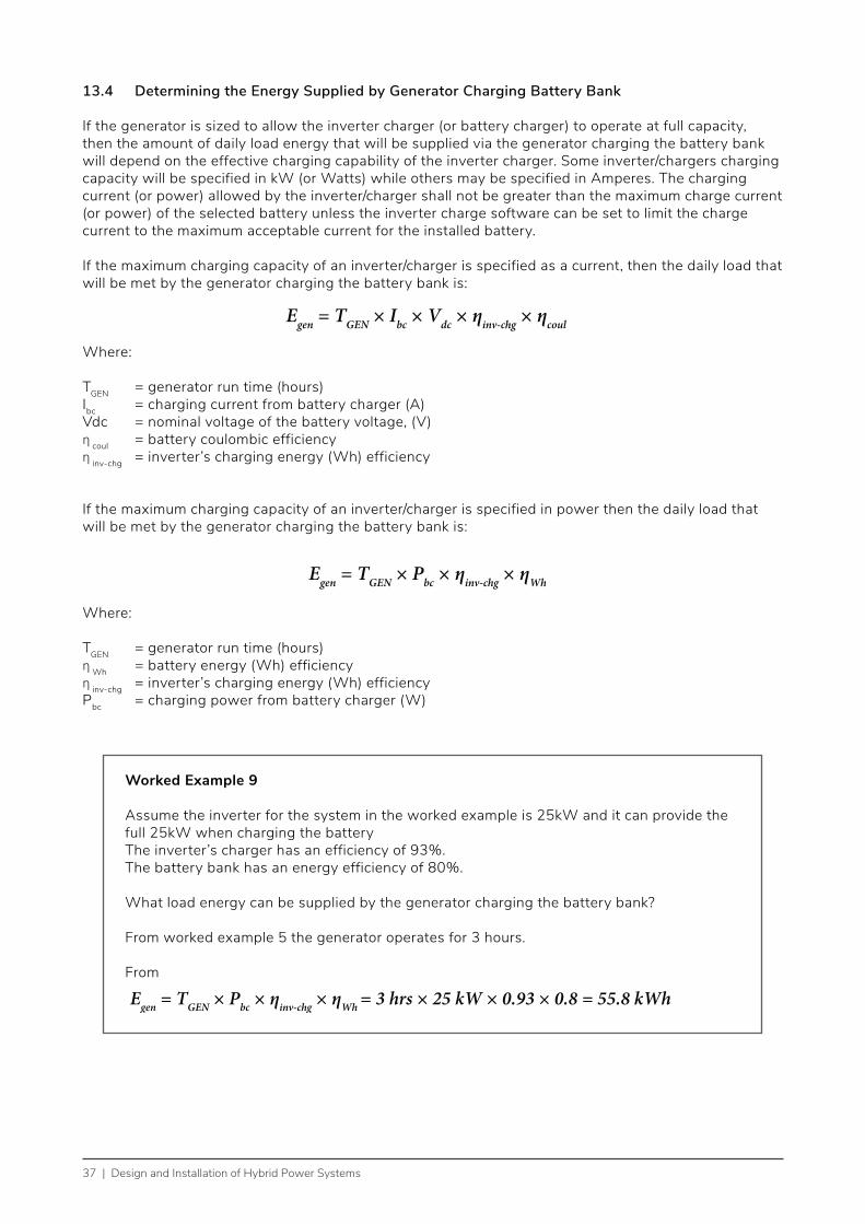
37 | Design and Installation of Hybrid Power Systems
13.4 Determining the Energy Supplied by Generator Charging Battery Bank
If the generator is sized to allow the inverter charger (or battery charger) to operate at full capacity, then the amount of daily load energy that will be supplied via the generator charging the battery bank will depend on the effective charging capability of the inverter charger. Some inverter/chargers charging capacity will be specified in kW (or Watts) while others may be specified in Amperes. The charging current (or power) allowed by the inverter/charger shall not be greater than the maximum charge current (or power) of the selected battery unless the inverter charge software can be set to limit the charge current to the maximum acceptable current for the installed battery.
If the maximum charging capacity of an inverter/charger is specified as a current, then the daily load that will be met by the generator charging the battery bank is:
Egen = TGEN × Ibc × Vdc × ηinv-chg × ηcoul
Where:
TGEN = generator run time (hours)Ibc = charging current from battery charger (A)Vdc = nominal voltage of the battery voltage, (V)η coul = battery coulombic efficiencyη inv-chg = inverter’s charging energy (Wh) efficiency
If the maximum charging capacity of an inverter/charger is specified in power then the daily load that will be met by the generator charging the battery bank is:
Egen = TGEN × Pbc × ηinv-chg × ηWh
Where:
TGEN = generator run time (hours)η Wh = battery energy (Wh) efficiencyη inv-chg = inverter’s charging energy (Wh) efficiencyPbc = charging power from battery charger (W)
Worked Example 9 Assume the inverter for the system in the worked example is 25kW and it can provide the full 25kW when charging the batteryThe inverter’s charger has an efficiency of 93%.The battery bank has an energy efficiency of 80%.
What load energy can be supplied by the generator charging the battery bank?
From worked example 5 the generator operates for 3 hours.
From
Egen = TGEN × Pbc × ηinv-chg × ηWh = 3 hrs × 25 kW × 0.93 × 0.8 = 55.8 kWh

Design and Installation of Hybrid Power Systems | 38
13.5 Determining the Daily Load Energy to be Provided by the PV Array
If the generator has the capacity to meet the loads and provide charging of the battery bank, the amount of daily load energy to be supplied by the PV array is:
Where: ELoad = Total Daily Energy RequirementEgen = Energy supplied by generator directlyEgen-batt = Energy supplied by generator charging battery bankEPV-dir = Energy supplied directly by PV arrayEPV-batt = Energy supplied directly by PV array charging battery
However, if the generator does not have the capacity to provide charging of the battery bank a different equation must be used. if the generator only has the capacity to meet the loads, the amount of daily load energy to be supplied by the PV array is:
In practice since the loads will vary over time the generator may still be able to charge the battery bank at some times but trying to estimate exactly how much is difficult and usually not very accurate. Assuming that no charging occurs from the generator is the conservative approach.
Once the amount of daily load energy to be supplied by the PV array is determined then the designer will need to determine the size of the array. How this is undertaken will depend on the configuration of the system. The different formulas are contained in Part 2 and Part 3 of the Off-grid PV Power System Design Guideline and the designer should refer to that guideline when determining the size of the array. The respective formulas have also been summarised in section 12.2 of this guideline and a summary of the different system losses is provided in section 14 of this guideline.
EPV = EPV-dir + EPV-batt = ELoad - Egen - Egen-batt
EPV = EPV-dir + EPV-batt = ELoad - Egen
Worked Example 10
Based on worked example 7 and 9, what is the load energy that shall be provided by the PV array assuming that the generator has the capacity to meet the loads and provide charging of the battery bank?
From example 6: ELoad = 200kWh and Egen = 50kWh
From worked example 8: Egen-batt=55.8kWh
Therefore Epv = 200 - 50 - 55.8 = 94.2kWh.
EPV = EPV-dir + EPV-batt = ELoad - Egen - Egen-batt

39 | Design and Installation of Hybrid Power Systems
14. Summary of Hybrid System LossesHybrid systems can consist of ac bus systems, dc bus systems or a combination of both. Trying to remember and apply all the formulas related to losses between the energy sources and the loads for the various configurations can be very difficult. It is best that the designer always first draws the configuration of the system that is proposed for the design and then determines the sub-system losses for that configuration among the various energy sources, (e.g. PV array, battery, generator) and the loads. These will be required when trying to determine the size of the PV array required. This section summarises the various losses in the different configurations.
14.1 System Efficiencies in a dc Bus System Supplying ac Loads
Figure 19 shows the various system losses in a dc bus system providing ac energy to loads. Table 2 summarises the typical losses for the many pathways between the energy sources and the loads.
PVArray
System Controller OR MPPT Controller
ηCON
BatteryBank
ηCOUL or ηBATT ηINV − CHG
ηINV ac Loads
Inverter-charger OR Discrete Battery Charger and Inverter
Generator
Case 1: Use ηCOUL
Case 2: Use ηBATT
Case 3: Use ηCOUL if charge
current speci�ed; ηBATT if not
Figure 19: System Losses in a dc bus configured hybrid system-excluding cable losses

Design and Installation of Hybrid Power Systems | 40
Table 2: System efficiency losses for dc bus system supplying ac loads
Case 1: Switched/PWM Solar controller.
The PV Array charges battery via a switching or PWM
controller & the battery inverter supplies ac loads.
The system is based upon Ah.
Case 2: MPPT Solar controller.
The PV array charges battery via a MPPT controller & the battery
inverter supplies ac loads.
The system is based upon Wh.
Note: Individual cable losses can be combined and stated as cable
losses (transmission losses) between PV array and inverter
or loads.
Case 3: Generator and inverter-charger.
When the generator is running, it can charge the battery via the inverter-charger and the
maximum charge current is based upon the battery
requirement and the maximum current rating for the charging
circuit in the inverter. When the generator is off the battery
inverter-charger supplies all the ac loads.
The system is based upon Ah.
Note: The inverter-charger could be bidirectional or
dc bus interactive.
1. Battery coulombic efficiency losses when charging (typ ~10%)
1. Cable losses between the PV array to MPPT (typ <1%)
1. Battery coulombic efficiency losses when charging (typ ~10%)
2. Battery inverter efficiency losses (typ ~4-12%)a
2. MPPT efficiency losses may also apply (typ ~4-5%)
2. Battery inverter efficiency losses (typ ~4-12%)
3. Cable losses between MPPT and battery (typ <1%)
4. Battery watt-hour efficiency losses when charging (typ ~10-30% depending on technology)
5. Cable losses between battery and battery inverter (typ <1%)
6. Battery inverter efficiency losses (typ ~4-12%)

41 | Design and Installation of Hybrid Power Systems
14.2 System Efficiencies in an ac Bus System Supplying ac Loads
Figure 20 shows the various system losses in an ac bus system providing ac energy to the loads. Table 3 summarises the typical losses for the many pathways between the loads and the energy sources.
Battery Bank
ηCOUL or ηWHηINV
PV Array
ηPVINV PV Inverter
ηINV − CHG
Generator
Case 4: Use ηWH
Case 5: Use ηCOUL if charge current
speci�ed; ηWH if notCase 6
ac Interactive Battery Inverter
ac Loads
Figure 20: System Losses in an ac bus configured hybrid system-excluding cable losses

Design and Installation of Hybrid Power Systems | 42
Table 3: System efficiency losses for ac bus system supplying ac loads
Case 4: PV array is con-nected to PV inverter, charges batteries via bat-tery inverter and batteries supply load.
The battery inverter would be ac bus interactive.
Case 5: generator powers the ac load and charges battery via the battery inverter. At times the bat-tery supplies none, some or all of the ac load.
The battery inverter would be ac bus interactive.
Case 6: PV array is connected to PV inverter and supplies ac loads directly.
1) Cables losses between the PV array to PV inverter (typ <1%)
1) Cable losses between the generator and battery inverter (typ <1%)
1) Cables losses between the PV array to PV inverter (typ <1%)
2) PV inverter efficiency losses (typ ~3-6%)
2) Battery inverter efficiency losses (typ ~4-12%) acting as charger
2) PV inverter efficiency losses (typ ~3-6%)
3) Cable losses between PV inverter and battery inverter (typ <1%)
3) Cable losses between battery inverter and battery (typ <1%)
4) Battery inverter efficiency losses (typ ~4-12%) acting as charger
4) Battery watt-hour efficiency losses (typ ~20%)
5) Cable losses between ac battery inverter and battery (typ <1%)
5) Cable losses between battery and battery inverter (typ <1%)
6) Battery watt-hour efficiency losses (typ ~20%)
6) Battery inverter efficiency losses (typ ~4-12%)
7) Cable losses between battery and battery inverter when inverting (typ <1%)
Note: If battery charging current from ac bus interactive battery inverter is specified then losses similar to that of Case 3 in Table 2 would be applied.8) Battery inverter
efficiency losses (typ ~4-12%)

43 | Design and Installation of Hybrid Power Systems
14.3 Combined ac and dc Bus System Configurations
Figure 21 shows the various system losses in a combined ac and dc bus system providing ac energy to loads. Table 2 and Table 3 provide the typical figures.
PV ArrayNote: Remember to apply necessary deratings
PV ArrayNote: Remember to apply necessary deratings
System Controller OR MPPT ControllerOperating e�ciency of MPPTcontroller if being used
ac Loads
ac Interactive Battery InverterCharging e�ciency OR inverter e�ciency
Generator
BatteryBattery coulombic e�ciency used when batterycharging supplied by: 1. PV array via PV array via switching or PWM controllers 2. Generator via ac interactive inverter and charge current providedBattery watt-hour e�ciency used when batterycharging supplied by: 1. PV array via MPPT 2. PV array via the interactive inverter 3. Generator via ac interactive inverter (kW rating)
Cable losses between PV & controller if MPPT is being used
Cable losses between PV & inverter
Cable lossesCable losses
Cable losses between ac interactive inverter & generator
PV InverterInverter e�ciency
Cable losses betweenbattery & controller if MPPT is being used
Figure 21: System Losses in a combined ac and dc bus configured hybrid system

Design and Installation of Hybrid Power Systems | 44
15. Installation of Hybrid SystemsThe installations of the PV array, battery bank, inverter and balance of system components are contained in the Off-grid PV Power Systems Installation Guideline. The relevant sections are referred to below and this section only highlights the installation of the fuelled generator and any additional requirements needed to integrate the generator into an Off-grid PV power system installation.
15.1 Array Installation
Refer to section 5 of the Off-grid PV Power Systems Installation Guideline for the installation of PV arrays. Depending on the size of the PV array with the hybrid system, the PV array may be broken into many sections each with their own separate solar controller and/or PV inverter.
15.2 Solar Controller and/or PV Inverter Installation
Refer to section 8 of the Off-grid PV Power Systems Installation Guideline for the installation of solar controllers and section 9 for the installation of PV inverters.
If the PV array installation does include multiple solar controllers then the number of controllers in parallel shall not be greater than that recommended by the manufacturer and the relevant intercommunications wiring shall be installed such that the controllers operate together.
15.3 Battery Installation
Refer to section 6 and 7 of the Off-grid PV Power Systems Installation Guideline for the installation of battery banks and the ventilation requirements.
In larger hybrid systems comprising multi cluster inverters, the system may be made up of a number of individual battery banks each connected to their own cluster of battery inverters and PV arrays.
15.4 Battery Inverter Installation
Refer to section 10 of the Off-grid PV Power Systems Installation Guideline for the installation of the battery inverters.
In small hybrid systems made up of inverter/chargers and dc or ac interactive inverters the fuelled generator will be electrically connected to the inverter along with communication/control cables to allow the inverter to stop/start the generator.
With larger systems the inverters may have multiple inverters interconnected in parallel clusters. The number of clusters shall not be greater than that recommended by the manufacturer and the relevant intercommunications wiring shall be installed such that one inverter (or cluster) acts as the “master” and the others the slaves.
Some system configurations may require the inverters’ electrical outputs to interconnect through a cluster control box (refer figure 10), this is where the generator will also be electrically connected.

45 | Design and Installation of Hybrid Power Systems
15.5 Battery Charger Installation
If the hybrid system includes a separate battery charger:• The battery charger shall be installed as to the manufacturer`s instructions• Installation of the battery charger should be near the batteries • Never install the battery charger on top or above the enclosure of batteries that emit explosive
gases or near the ventilation vents. • Battery chargers dissipate heat so there must be sufficient ventilation for removing heat from these
sensitive pieces of equipment. Always follow the manufacturer’s recommendations for installation, ventilation and clearances around heat sinks.
• If a battery charger is installed outside, the charger should have an IP (Ingress Protection) rating of at least IP56. Due to the humidity and high salt environment in the Pacific region it is recommended that all chargers should have this IP rating or higher.
• Battery chargers should be installed in dust free locations; • Battery chargers can be heavy, it is important that the surface on which they will be mounted is
appropriately weight-bearing• Battery chargers are not to be installed in direct sunlight.
15.6 Generator Installation
• The generator should be installed in a separate room or shed that only contains the generator and ancillary equipment such as its controller, fuel tank, etc.
• The generator enclosure should be lockable to provide security against tampering, theft or accidental contact by unauthorised persons.
• The foundation supporting the generator is generally a concrete slab that is reinforced and capable of supporting 125% of the pressure exerted by the generator, including fuel, and typically between one and two times the mass of the overall genset.
• The location must be easy to access and cable distances to other components is minimised, while still being far enough away from dwellings to avoid annoyance to residents due to noise and exhaust fumes.
• Combustion and Cooling Air Supply: Air is essential both for the combustion of fuel in the engine and the cooling of the equipment. As a rule of thumb, cooling requires six to eight times as much air as combustion. Air intake and exhaust vents should be located to permit smooth air flow over the set. The air should be as cool as possible at the time it reaches the air cleaner. In excessively dusty conditions, additional intake filtration may be required. In order to minimise the ingress of dust and dirt, cooling fans/vents should not face the predominant wind directions.
• Fuel Supply: Depending on the size of the generator, the fuel tank may be a small gravity feed unit, a base mounted unit, an external day tank or an underground tank. Fuel storage may be subject to local regulations or standards so installers must check with the relevant government department. Generally, this will mean storage is kept away from potential sources of ignition (including the generator and its associated electrical equipment), provision of bunding or other means of containing a spill from the primary storage vessel is usually required. Warning signs and access control provisions will almost certainly be required with their content depending on the quantity of fuel stored and the type of storage installed.
• Exhaust: If the flow of exhaust gases is restricted, back pressure will reduce the power output of the engine. The exhaust pipe should be of adequate diameter for its length, and if bends are to be included, they should be of long radius. If the exhaust pipe is mounted to a fixed structure, a flexible fitting must be included to isolate it from engine vibration and to provide for dimensional changes due to temperature changes. Because heat reduces an engine’s efficiency, exhaust components adjacent to the generator should be lagged with heat resistant insulating material to reduce heating engine components.

Design and Installation of Hybrid Power Systems | 46
• Mechanical and Exhaust Noise: Noise from the generator includes both general mechanical noise and noise from the exhaust. To attenuate mechanical noise, it will be necessary to insulate the interior of the generator room with a sound retardant material. It is common to fit noise attenuating louvres to the air intakes and outlets. Exhaust noise can be lessened by fitting a silencer or muffler. The degree of attenuation depends on the quality (and cost) of the silencer. The direction at which exhaust is discharged will also affect noise levels.
• Generator Starting Battery System: The starting battery must have sufficient capacity to crank the engine under cold start conditions, and to attempt multiple starts if required. An auxiliary battery charger must be installed if the generator is not guaranteed to run for 4 to 6 hours at least once every week.
• Ancillary Electrical Equipment: Electrical installation work must be carried out by a licensed electrician. A circuit breaker will be required for the ac outputs and appropriate instruments should be fitted.
• Cabling: (also refer to section 15.7) Cabling should be supported, protected from damage of all types (including vermin, temperature, fuel and lubricants, external influences etc.) and installed in accordance with relevant local rules or standards such as those from Australia/New Zealand, the National Electrical Code (USA) or international standards from the IEC.. Particular attention should be paid to the inclusion of an anti-vibration loop between where the cable is secured to the generator and where it is secured to the remainder of the installation.

47 | Design and Installation of Hybrid Power Systems
15.7 PV Array Wiring
Refer to section 11, 12 and 13 of the Off-grid PV Power Systems Installation Guideline for the safe wiring installation practices (section 11), the wiring of the PV array (section 12) and interconnection wiring to the solar controller/PV inverter (section 13).
15.8 Battery Cabling
Refer to section 14, 15 and 16 of the Off-grid PV Power Systems Installation Guideline for the installation of cables between the battery and solar controllers (section 14 and 15) and battery inverters (section 16).
15.9 Voltage Drop
The voltage drop between the generator and the interconnection with the system at the inverter or cluster control shall not exceed 5%.
Refer to section 17 of the Off-grid PV Power Systems Installation Guideline for the formulas for determining voltage drop and also the recommended voltage drops for the rest of the hybrid system.
15.10 Protection Requirements
The cable between the generator and the hybrid system shall be protected by a suitably rated circuit breaker.Refer to section 18 of the Off-grid PV Power Systems Installation Guideline for the protection requirements for the rest of the hybrid system.
15.11 Disconnection (isolation) Requirements
The generator shall be capable of being isolated from the rest of the hybrid system by a load breaking disconnection device. The circuit breaker mentioned in 15.10 can meet this requirement.
The generator control system shall include a disconnection device to isolate the remote control wires to the inverter and other control equipment (e.g. a remote starting switch) that can send a signal to start the generator.
Refer to section 19 of the Off-grid PV Power Systems Installation Guideline for the disconnection (isolation) requirements for the rest of the hybrid system.
15.12 Earthing (Grounding)
The conductive metal casing of the fuelled generator shall be bonded to earth (ground)
Refer to section 20 of the Off-grid PV Power Systems Installation Guideline for the earthing (grounding) requirements for the rest of the hybrid system.

Design and Installation of Hybrid Power Systems | 48
15.13 Shutdown Procedure
The process for shutting down of the generator should be included in the system shutdown procedure.
Refer to section 24 of the Off-grid PV Power Systems Installation Guideline for the shutdown procedure for the rest of the hybrid system.
15.14 Signage
A warning sign indicating that the generator can start automatically at any time should be positioned in a prominent location near the generator.
Refer to section 26 of the Off-grid PV Power Systems Installation Guideline for the signage requirements for the rest of the hybrid system.
15.15 Commissioning
Commissioning of the system shall include:• Starting the generator to determine that it operates properly including measuring its operating
voltage and frequency;• Testing that the generator can start and stop through being remotely controlled by the inverter and
any other starting control devices; and• Testing to show that the ac and dc bus interactive inverters synchronise with the generator and can
also operate in charging mode when generator is operating.
Refer to section 27 of the Off-grid PV Power Systems Installation Guideline for the commissioning requirements for the rest of the hybrid system
15.16 Documentation
All manuals related to the generator and a service book for maintenance should be included with the system documentation provided to the client.Refer to section 28 of the Off-grid PV Power Systems Installation Guideline for the documentation requirements for the rest of the hybrid system