hvacsim+ building systems and equipment simulation program
TRANSCRIPT
AlllDb DS^mt
NBStR 86-3331
HVACSIM''' Building Systems andEquipment Simulation Program:Building Loads Calculation
Reference publications
Cheol Park
Daniel R. Clark
George E. Kelly
U.S. DEPARTMENT OF COMMERCENational Bureau of Standards
National Engineering Laboratory
Center for Building Technology
Building Equipment Division
Gaithersburg, MD 20899
February 1986
^QC100
.056
86-3331
1986
jildings and Community Systemstment of Energy
Engineering Laboratory
tment of Defense

NBSfifiSEABCH INFORMATIOM
CENTER
NBSIR 86-3331' • »
HVACSIM-^ BUILDING SYSTEMS ANDEQUIPMENT SIMULATION PROGRAM:BUILDING LOADS CALCULATION
I00
U i’Cc*
Cheol Park
Daniel R. Clark
George E. Kelly
U.S. DEPARTMENT OF COMMERCENational Bureau of Standards
National Engineering Laboratory
Center for Building Technology
Building Equipment Division
Gaithersburg, MD 20899
February 1986
Sponsored by:
Office of Buildings and Community SystemsU.S. Department of Energy
Naval Civil Engineering Laboratory
U.S. Department of Defense
U.S. DEPARTMENT OF COMMERCE, Malcolm Baldrige, Secretary
NATIONAL BUREAU OF STANDARDS, Ernest Ambler. Director

KJr-n
mnm»om rxdthfevttSICSS"
'f'/ ,-
m -m
s;a
>\reee-M mawt
>^MA^'8M37|!y^ OvfiOJm '*'Mt83AVH ** *
*cs
TM^t/rqiuoa^3»q nfftius-iAO acApj ovriQjiua's
"E
iv#
•' i f.
#»• io0itt!
4taf3 .M 4 »ift1
I#* ** ^ |/|^Q
^'li'jAQMi i«
I
IMSIvi
*
mt
304^1MV03 =»0 T4^3Mt,lA'^aa i'ilj
iswubn*;®' )r
r'ohi'Mwi^j ii.f»t>iif»vl
Y904or#fl>«^'^nfN4i#5 hi^ r«i(^'3 ’'*!
0fk4 ,p»L Mhurtf^t^'iK r
YHmxrrtrnoO tm« V ,tHO i*"
Yi?i<»r>3 toinomjii. *^ ?
fwr^iortiij t^li##n 4 o/i:> Wv«3
».5fiohiO b jtti^n<iC|nO
•'t
-41
=W5 tVI 3Vt R>MIr»0 9JKT^ y*'j
f*tm3 ,ftcmi.,?k«4T6 ir> UAiy^ut anjiionaM
Ljj*'- V
<^t-
liJa

ABSTRACT
A non-proprietary building system simulation program called HVACSIM^, wbicb
stands for HVAC SIMulation PLUS other systems, has been developed at the
National Bureau of Standards (NBS) in an effort to understand the dynamic
interactions between a building shell, an HVAC system, and building controls.
HVACSIM^ consists of a main simulation program, a library of HVAC system
component models, a building shell model, and interactive front end input data
generation programs.
The main simulation program employs a hierarchical, modular approach and
advanced equation solving techniques to perform dynamic simulations of
building/HVAC/control systems. In the building shell model, a fixed time step
selected by the user is employed, while a variable time step approach is used
in the HVAC and control systems portion of a simulation and the zone model.
This report presents the overall architecture of the HVACSIM^ program,
algorithms used in the main simulation program, a brief discussion of the
numerical methods used in solving a system of non-linear simultaneous
equations, integrating stiff ordinary differential equations and interpolating
data and descriptions of the building shell and zone models. Conduction
transfer functions, weather data, and simulation procedure are also described.
This report is the third document, which describes the building model,
supplied with HVACSIM^.
Key words: building dynamics; building simulation; building systemmodeling; computer s imul at ion programs; control dynamics;dynamic modeling of building systems; dynamic performance ofbuilding systems; dynamic simulations; HVAC system simulations;HVACSIM^
iii

ACKN(MLED6EMENTS
The authors are indebted to the Building Systems Division, U.S. Department of
Energy, and the Naval Civil Engineering Laboratory, U.S. Department of
Defense, for funding this project, and gratefully acknowledge Dr. C. Ray Hill
for his original work of the main simulation program, MODSIN, during a year at
MBS as a research associate, Mr. George N. Walton for his helpful suggestions,
and Mr. William B. May, who directed the development of the front end program
HVAOGEN and provided hardware and software support for this project. Valuable
contributions in developing HVACSIM^ were made by Mr. Scott Hildebrand, Mr.
David Harris, Mr. Chris Rasmussen, and Mr. Juan Lopez, who were visiting
workers at NBS. The authors thank Mrs. Janet I. Clark for typing this
report.
DISCLAIMER
The program described in this report is furnished by the government and is
accepted and used by any recipient with the express understanding that the
United States Government makes no warranty, expressed or implied, concerning
the accuracy, completeness, reliability, usability, or suitability for any
particular purpose of the information and data contained in this program or
furnished in connection therewith, and the United States shall be under no
1 iabil ity what soever to any person by reason of any use made thereof. This
program belongs to the government. Therefore, the recipient further agrees
not to assert any proprietary rights therein or to represent this program to
anyone as other than a government program.
iv

TABLE OF CONTENTS
ABSTRACT iii
ACKNOWLEDGMENTS iv
DISCLAIMER iv
LIST OF FIGURES vii
1. INIBODUCTION 1
2. ARCHITECTDRE OF HVACSIM"^ 3
3. MODULAR SIMULATION PROGRAM, MODSIM 8
3.1 Hierarchical, Modular Approach 8
3.2 Controls of State Variables and Blocks.. 10
3.3 Hybrid Simulation Time Steps 11
3.4 Time Dependent Boundary Conditions 12
4. NUMERICAL METHODS USED IN MODSIM 14
4.1 Nonlinear Equation Solver 144.2 Integration of Stiff Ordinary Differential Equations.. 17
4.3 Interpolation of Data 23
5. BUILDING LOADS CALCULATION 25
5.1 TYPE 50: Zone Envelope 27
5.2 TYPE 51: Building Surface 31
5.3 TYPE 52: Zone Model 395.4 TYPE 53: Weather Input 46
6. UTILITY ROUTINES FOR BUILDING LOADS CALCULATION 486.1 Properties of Moist Air 486.2 Air Exchange Rate 49
6.3 MRT View Factors 49
6.4 Heat Transfer Coefficients 50
7. CONDUCTION TRANSFER FUNCTION CALCULATION 53
7.1 Overview of CTFGEN 53
7.2 Heat Conduction of a Multilayered Construct 54
7.3 Response Factors 587.4 Conduction Transfer Functions 61
V
8. WEATHER DATA 648.1 Weather Tape Reading Routine 648.2 Weather Data File Generation 65
9. SIMULATION PROCEDURE 73
9.1 Preprocessing - Input Data Generation 73
9.2 Simulation 76
9.3 Postprocessing - Output Data Analysis 76
10. REFERENCES 77
APPENDIX A: Short Descriptions of Functions and Subroutines in
HVACSIM"^ 81
APPENDIX B: Worksheets for Data Entry for Type 50. 51, 52, and 53.... 94
APPENDIX C: Example 1 - One-Zone Building Model 98
APPENDIX D: Example 2 - Three-Zone Building Model 150
vi
LIST OF FIGURES
Figure 1 Flow diagram of programs and data files of HVACSIM^ 4
Figure 2 The structure of MODSIM 6
Figure 3 Hierarchical simulation setup 9
Figure 4 Simplified flow diagram for the iterative procedure in
solving simultaneous, nonlinear equations 18
Figure 5 Simplified flow chart of the algorithm for integration
of stiff ordinary differential equations 22
Figure 6 A multilayer construct 57
vii

a'
Iwi3Sr^|«#|t««r i
t
4«« n'
,if- »««w j^
.^™-v--. * _' ,jtf '* i;.<‘®» ’'•
'< # y
^
t^'. m'r. Mi n;
. m'S.iS ^ * '•"’*'•.<* * . » »
•
»%t* II I iW'^lil =I . • t»cr| 1
1
: i*
“ aVii f
'
f!
IJBI;
'i., . ' ti
'i”
U*'" „4K:r*J' I"*' " i*.'
'
'L-\MJk.
i,‘ 'M
Hfi^n' j M,
If
'
Vh
t'

1 . INTRODUCTION
Computer simulations have been a popular means of analyzing building energy
use. Compared with experimental investigations, computer simulations do not
require installation of various expensive instruments. Simple changes in
input data to a simulation model can evaluate their impacts on the model.
In an effort to carry out simulation studies involving the dynamic
interactions between a building shell, an HVAC system, and building controls,
a non-proprietary building system simulation program called HVACSIM^ has been
developed at the National Bureau of Standards (NBS). The program HVACSIM^,
which stands for HVAC SIHulation PLUS other systems, is capable of modeling
the HVAC (heating, ventilation, and air-conditioning) system plus HVAC
controls, the building shell, the heating/cooling plant, and energy management
and control systems (EMC^) algorithms. Although the current version of the
HVACSIM^ has not implemented the EHCS algorithms yet, these may be added by a
user interested in such applications, and familiar with Fortran programming.
The HVACSIM^ consists of a main simulation program, a library of HVAC system
components models, a building shell model, and interactive front end data
generation programs. The main program is called MODSIM and employs a
hierarchical, modular approach and advanced equation solving techniques to
perform dynamic simulations of buil ding/HVAC/control systems. The modular
approach is based upon the methodology used in the TRNSYS program [1]. In the
building shell model, a fixed (but user selectable) time step method is used,
while a variable time step approach is employed in the HVAC and control
1

systems portion and tlie zone model. This hybrid time step method is believed
to be unique in the building systems programs.
The HVACSIM^ program has been developed primarily as a research tool for whole
building system studies. Flexibility of the HVACSIM^ allows the simulation of
HVAC components, control systems, the building shell, or any combination. The
program is written in ANSI Standard Fortran 77. Fully structured programming
makes the code relatively easy for prograaimers to understand and maintain.
Some important features of HVACSIM^ were previously introduced [2,3] and the
results of some case studies were published [4,5]. A general overview of
EVACSIM^ was also presented [5]. Documentation for HVACSIM^ consists
primarily of three publications: a Reference Manual [7], a Users Guide [8],
and this report. The building loads calculation routines are relatively
recent additions to HVACSIM'*', and as such are not described in the Reference
Manual or the Users Guide. This report serves as reference manual and users
guide for the building load portions of HVACSIM^. In addition, mathematical
details of the numerical methods used in HVACSIM^ are presented. Sample
simulations for building load calculations are appended.
2

2 . ARCHIIECTUEE OF HVACSIM^
The various portions of HVACSIH^ can be divided into three categories:
preprocessing, simulation, and postprocessing. Prior to performing a
simulation, the data files for a particular building system simulation must be
provided. This can be accomplished using programs in the preprocessing group.
After a simulation, evaluation of outputs from the simulation is made using
the postprocessing program.
Figure 1 shows a flow diagram of programs and data files comprising HVACSIM'*'.
During the preprocessing, a work file for simulation is created by the
interactive front end program, HVAOGQf [8]. This work file is then converted
into the model definition file by the program SLIMCOM Ihe model definition
file has the format which the main program HODSIH requires. The work file can
be edited interactively by the HVAOGEN program. In generating the simulation
work file, HVACXjEN employs a data file containing component model information.
When a building shell is involved in a simulation, data files of weather
conditions and conduction transfer functions for multilayered constructs must
also be created. The program RDTAPE reads a weather tape (SOLMET, TMY, ULY,
or WYEC tape) or equivalent and selects a portion of the weather data that is
of interest. The selected weather data is transformed into the proper input
form for HODSIM by the program CSWDTA. If a weather tape is not available or
information from a weather tape is missing, the CRWDTA program produces a
design day weather data file.
3

Preprocessing
LComponent Model
Configuration 7
Lsimulation
Work nie
( WeatherA
• HVACQEN
r f rVt
* 7
ROTAPE
CRWDTA
ModelDefinition File
Selected
Weather Data
WeatherData File
7
7-
/jThermal Propertlea
Bulldirtg Materials7 CTFQENConductionTransfer
Functions
Simulation
zBoundary Variable
Data nie 7
ZSimulation
Control Data 7
MODSIM ^ Summary /
Outputs j
i.Raw Output
Data 7n
Initialization File 7Post processing
SORTSS
Plots
7 Sorted Dafor Plotting
Figure 1. Flow diagram of programs and data files of H\'ACSIM^
4

The conduction transfer functions of mul ti 1 ayered bui Iding constructs are
generated by the CTFGEN program. Except for the front end routines of CTFGEN
the main routines in CTFGEN are taken from the TARP program by Walton [9],
The thermal properties of building materials (thickness, thermal conductivity,
density, specific heat, and thermal resistance) can be entered into the data
bank by using CTFGEN and multilayered constructs can be formed interactively.
The MODSIM program is the heart of HVACSIM^. As shown in Figure 2, the MODSIM
program consists of a main drive program and many subprograms for input/output
operation, block and state variable status control, integration of stiff
ordinary differential equations, solving of a system of simultaneous non-
linear algebraic equations, component models of HVAC, controls, building
model, and supporting utility.
The simulation program, MODSIM, calls the model definition, conduction
transfer functions, weather, and boundary data files. The boundary data file
can be created with a conventional editor. The state variables associated
with this boundary data file are assigned when HVAGGEN generates the work file
for a particular simulation.
During the execution of MODSIM, simulation control input data can be entered
interactively on a terminal. After a successful simulation, three data files
are generated. These are the summary, raw output, and initialization data
files. After renaming the initialization file as the input file to MODSIM, a
5
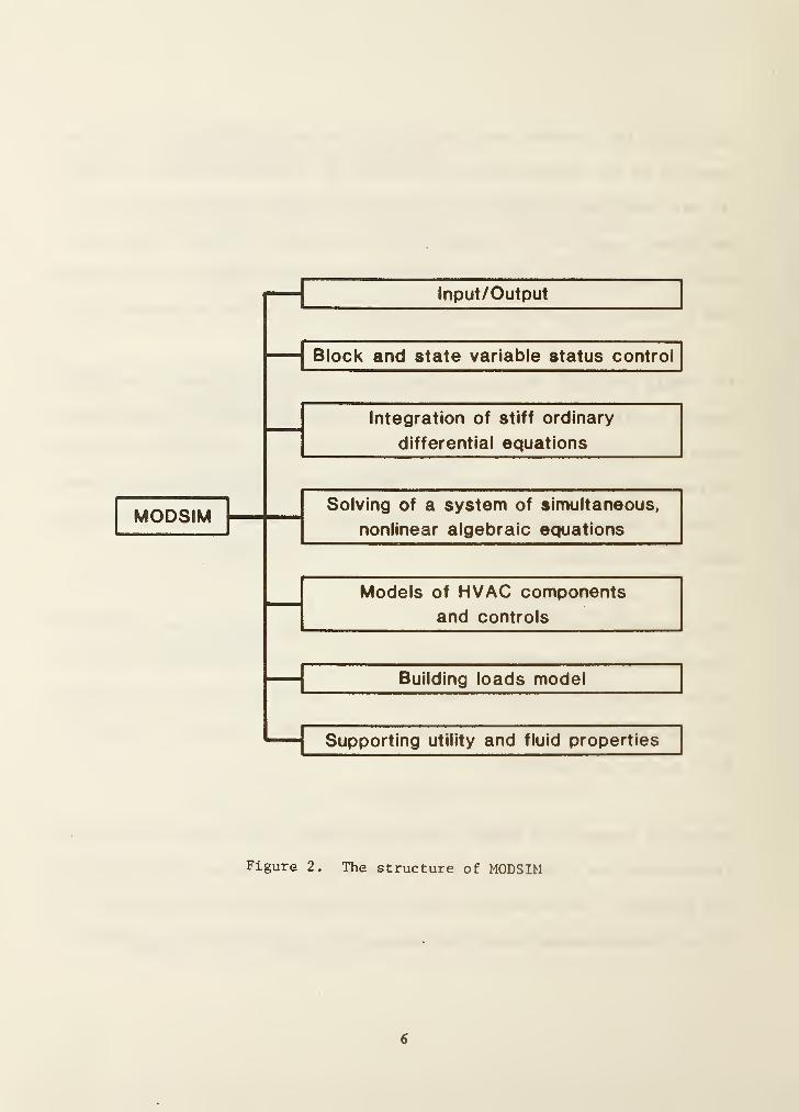
Figure 2. The structure of MODSIM
6

new simulation can be performed starting from tbe point where the previous
simulation ended.
Postprocessing is necessary if graphical presentation of the raw outputs is
desired. The program, SORTSB, sorts the raw output data. The outputs of
these programs may then be used for plotting with a user- suppl ied graphic
routine.
It should be noted that the architecture of HVACSIM^ had been changed after
the overview paper [6] was presented.
7
3. MODULAR SIMULATION PROGRAM, MODSIM
MODSIM stands for MOOnlar SIMnlation. Many ideas for the design of MODSIM
came from the TRNSYS program, which was developed at the University of
Wisconsin Solar Energy Laboratory [1]. Hie original MODSIM was first written
in Fortran IV by Hill [3]. Since then, MODSIM has been rewritten in
structured Fortran 77 and modified significantly. Important features of the
current MODSIM program are described below.
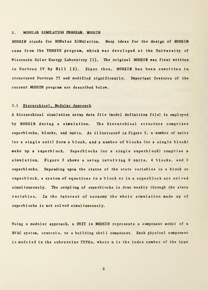
3.1 Hierarchical. Modular Approach
A hierarchical simulation setup data file (model definition file) is employed
by MODSIM during a simulation. The hierarchical structure comprises
superblocks, blocks, and units. As illustrated in Figure 3, a number of units
(or a single unit) form a block, and a number of blocks (or a single block)
make up a superblock. Superblocks (or a single superblock) comprise a
simulation. Figure 3 shows a setup involving 8 units, 4 blocks, and 2
superblocks. Depending upon the status of the state variables in a block or
superblock, a system of equations in a block or in a superblock are solved
simultaneously. The coupling of superblocks is done weakly through the state
variables. In the interest of economy the whole simulation made up of
superblocks is not solved simultaneously.
Using a modular approach, a UNIT in MODSIM represents a component model of a
HVAC system, controls, or a building shell component. Each physical component
is modeled in the subroutine TTPEn, where n is the index number of the type
8

Figure 3. Hierarchical simulation setup
9

assigned to the specific component. More than one unit can call the same
TYPEn subroutine if the same component model is used more than once. For
example, if UNIT 2 and UNIT 4 in Figure 3 represent two different fans in the
HVAC system, the same TYPEl subroutine for a fan (n=l) can be used in the
simulation. Each subroutine of component model has inputs, outputs,
parameters, and a workspace vector for saving intermediate results. The
component model configuration data file, which is an input file to the HVACGEN
program, contains information on the numbers of inputs, outputs, parameters,
elements in the saved workspace vector, and a description of the inputs,
outputs, and parameters.
Each UNIT has its distinct index number for input and output variables, and
values of parameters. This information is transmitted to the corresponding
TYPEn subroutine through arguments.
This hierarchical, modular approach provides great flexibility in setting up a
simulation model. The actual breakdown of a building system into blocks and
superblocks is left to the user and depends upon the nature of the system and
the type of interactions among its various components. Proper 'blocking*
produces good simulation results and reduces computational time. Improper
'blocking' of a simulation model can result in a poor simulation.
3 .2 Controls of State Variables and Blocks
During a simulation, a large portion of time is spent in solving the system of
simultaneous equations. Reduction of the number of equations solved
10

simTil taneously in a block or a snperblock can result in considerable
computational savings. In MODSIM, vben some of the state variables reach
steady state, these variables are removed from the system of state variables
that are solved simultaneously, and put aside (or 'frozen'} until deviations
from the stea^^state values are encountered. The criterion for freezing a
variable is chosen as
1 1 1
|^n+l“ ^n1
- 2erj |+®a
(3.1)
here^
state variables at the current and the previous
time, and e_ and e, are the relative and the absolute error tolerance,
respectively. These error tolerances must be specified vhen the simulation
work file is created using HVAOGEN.
Similarly, a block can be inactivated (or frozen) if al 1 the input variables
to the block are frozen. A block is marked active as soon as one of its block
inputs becomes unfrozen. When a block is frozen, it is no longer necessary to
monitor the frozen state variables in the block.
3 .3 Hybrid Simulation Time Steps
The MODSIM program incorporates tvo different types of time steps. One of
them is a fixed time step, and the other is a variable time step. The
building shell model uses a user— sel ected fixed time interval because the
building shell model needs the conduction transfer functions of building
constructs vhich are calculated on the basis of uniformly distributed time
11
sampling. In addition, weather data is usnal I7 provided on the hourly basis.
Variable time steps are used for all other component models.
This multi-time step approach has its advantage in saving computation time.
Many component models for HVAC and controls systems involve ordinary
differential equations. When the system is unsteady, a large time step
invites numerical instability. To prevent this instability, small time
intervals are necessary at an initial startup of a simulation or during a
period when sudden change occurs. After the system become s stabi 1 ized, the
use of short time step is no longer needed and is wasteful.
Each superblock in a simulation is an independent subsystem in the sense that
it proceeds forward in time independently. The variable time step it
determined for each superblock, excluding the superblock for the building
shell, by the integration routine used to solve the systems of differential
equations. The largest time step allowed in a superblock is, however, limited
to the fixed time step used in the building shell model.
3 .4 Time Dependent Boundary Conditions
A state variable which is external to the system being simulated can be
designated as a boundary variable when the simulation work file is generated.
The boundary variables may be constant or time dependent. Data at the
boundary variables are stored in the boundary data file and read as the
simulation progresses. Time intervals in this data file are not required to
12
be equal, since a third order Lagrangian interpolation method is used.
Sometimes a change in a boundary variable may be discontinuous (e.g., set
point change). In such cases, the integration routine of differential
equations is reset at the time of discontinuity to bring the simulation time
step to a minimum value. This kind of reset condition is signaled by
including in the boundary data file two different data values of a boundary
variable at a given time.
13

4. NUMERICAL METHODS IN MODSIM
The ntunerical methods employed in the MODSIM program involve techniques for
solving systems of simultaneous nonlinear algebraic equations, integrating
stiff ordinary differential equations, and interpolating data sampled in
either a fixed period or variable time intervals. A large number of
subprograms in the ItK)DSIN are related to these numerical algorithms.
4 . 1 Nonlinear Equation Solver
The subroutine SNSQ with its associate subprograms is used in MODSIM. This
routine is a part of the mathematical software package SNLSE in the CMLIB
package, NBS [10], and was coded by Hiebert at Sandia National Laboratories
by combining the HYBRD and HYBRDJ in the MINPACE code developed by Argonne
National Laboratories [11]. The method used in the SNSQ program is based on
Powell's hybrid method [12]. Minor modifications were made to the SNSQ
routine to achieve better simulations with HVACSIM^.
A brief mathematical description of the SNSQ routine is presented following
closely the approach used in the paper by Hiebert [11].
The system of nonlinear equations can be written in vector form as
f (x) = 0 (4.1)
where
l = [tl- *2 3 = Cxi. (4.2)
Expanding f in a Taylor series, and neglecting the high order terms, the
14

linearized, approximate system becomes
f(x*) f(x^) + J(x^) (x* - x^) (4.3)
V Vwhere J(x ) is a Jacobian evaluated at x .
If X* is the solution vector of the system, then
f(x*) = 0.
The general iteration equation for given x^ near x* becomes
^fcfl = . (4.4)
The Newton step of the nonlinear system. Ax, can be expressed as
Ax = x^ -J"^(x‘^)f(x^) (4.5)
In efforts to reduce the number of calculations involved with this approach, a
quasi-Newton method is used in SNSQ. This method approximates the Jacobian
using the Broyden's rank-one update [13] instead of calculating the full
Jacobian at each iteration. The Jacobian is calculated at the starting point
by either the user-supplied subroutine or a forward-difference approximation,
but it is not recalculated until the rank-one method fails to give
satisfactory progress. If is the approximation of the Jacobian at the kth
iteration, then the updated Jacobian [14] is
®k+l=
^k ^®k% Xi.)5LV^\^k»
where ^ - x^, Vj^ = l(x^^ ^)“l(x^) , and fl'^k is the transpose of £^. In
the SNSQ routine, the inverse Broyden update is employed. With the inverse
Broyden update method, the inverse of the approximate Jacobian, is stored
and updated at each iteration.
15

The local convergence of the quasi-Newton method is snperl inear, and required
arithmetic operation per iteration is only O(n^), while the number of function
evaluations per iteration is also only n. The shortcoming of the quasi-Newton
method is that a good initial guess must be made for successful convergence.
To improve this property, Powell [12] suggested a hybrid method.
The hybrid step is a combination of the quasi-Newton and gradient step. The
gradient step is chosen to minimize the Euclidean norm of the residuals. The
Gauss-Newton [15] and the steepest scaled gradient steps are actually
incorporated in the SNSQ routine. The convergence test is successful so that
is a solution vector if the following condition is satisfied:
Il4k - s‘)ll <
or if f(z) = 0. In the above equation, d^ is the diagonal component of the
transformed Jacobian matrix using QR-factorization, e^ is the error tolerance
usually specified by the user, and the double bars denote the norms. In
HVACSIM^, the value of e^ is specif led when the model definition file is
created by the HVACGEN front-end program. Although the square-root of the
machine precision [16] is recommended for the value of e^ in the SNSQ routine,
the choice of the value depends upon the particular simulation setup and its
initial values. As a rule of thumb, e^ may be greater than or equal to the
sum of e_ and e..r a
The bl ock/ superb lock structures, defined when a simulation setup is made, also
strongly influence the convergence characteristics. Even though the use of
hybrid step improves the convergence properties, making a good guess for
16

initial conditions is very important to ensure a successful simulation.
As an example. Figure 4 shows the simplified flow diagram for the iterative
procedure when and X2
are solved simultaneously and x^ and x^ remain
constant at a time step. In the TYPE subroutines for two units in a block,
x^' and X2
' are determined using the function and ¥2 * respectively.
Residual functions can be written as
fl(xi,X2,X3,X4) = xj' - xj = Fi (x2,i3) -
f2<Xi,X2,X3,X4) = X2
' - X2 = F2 (xj,X4) - X
2 (4.8)
These function vectors, fj^ and f2 , and state variables, x^, are entered into
the equation solver. When the convergence criterion as given by equation
(4.7) is met, the iteraction ceases, and the solutions x^* and X2* satisfy fj^
= f2 - 0. After the solutions are obtained, the simulation time is increased
by h, which is either variable time step or fixed.
4 .2 Integration of Stiff Ordinary Differential Equations
The use of variable time step and variable order integration techniques to
solve sets of differential equations can reduce the amount of computer time
required for dynamic simulations significantly. The algorithm employed is the
one developed by Brayton, Gustavson and Hachtel [17]. This is an extension of
the famous Gear algorithm called DIFSUB [18], which uses the backward
differential formulas associated with Nordsieck's method [19].
17

Figure 4. Simplified flow diagram for the iterative procedure In
solving simultaneous, nonlinear equations
18
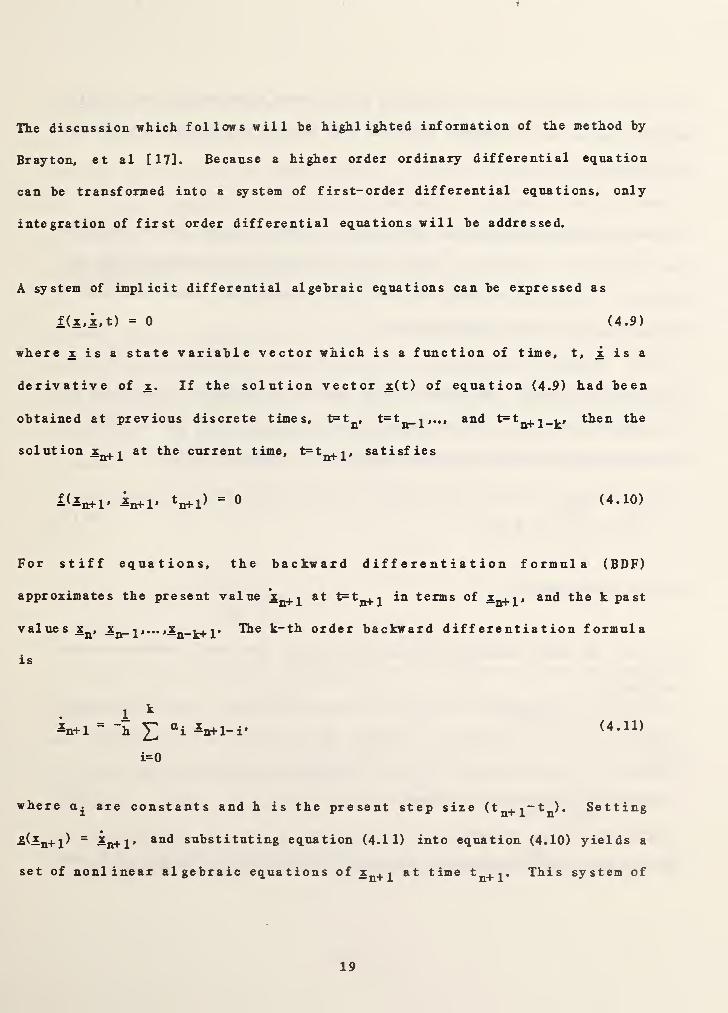
Tlie discussion whicli follows will be highlighted information of the method by
Brayton, et al [17]. Because a higher order ordinary differential equation
can be transformed into a system of first-order differential equations, only
integration of first order differential equations will be addressed.
A system of implicit differential algebraic equations can be expressed as
l(x,x,t) = 0 (4.9)
where x is a state variable vector which is a function of time, t, x is a
derivative of x. If the solution vector x(t) of equation (4.9) had been
obtained at previous discrete times, t=t^^, t=tj^j^,.., and then the
solution Xjj^
2
current time, satisfies
Kin+l* —n+1* ^n+1^“ ® (4.10)
For stiff equations, the backward differentiation formula (BDF)
approximates the present value at in terms of and the k past
values Xj^, ^® k-th order backward differentiation formula
is
k
2 ®i -n+l-i'
i=0
(4.11)
where are constants and h is the present step size (fn+i“fn)* Setting
a(a^+ 2) ~ ^n+1' substituting equation (4.11) into equation (4.10) yields a
set of nonlinear algebraic equations at time This system of
19

nonlinear equations can be solved by a nonlinear equation solver. In the
MODSIM program, the previously described SNSQ routine is employed to solve the
equations.
At the beginning of simulation, the initial values of at t=0 is used with
order k=l for x^. Knowing x^ and x^, the new value X2
is computed using \.< 2 ,
and so on. The maximum order of k has been limited to 6 since the order k
seldom exceeds 6 in most applications.
As discussed already, the Newton method requires a reasonably good guess for
the initial iteration. The predicted value of for the initial guest is
formulated using the same regressor expression in equation (4.11).
where constants.
For the k-th order backward differential formula, the local truncation error
is given by
k+1
-n+l-i (4.12)
i=l
( 4 . 13 )
where
^n+1 ^n-k
h( 4 . 14 )
and the term 0(h^**'^) represents higher-order terms in the step size of degrees
20

greater than or equal to k+2.
Although the algorithm for computation of and Yj presented by Brayton, et
al. is very complex, it was coded in MODSIM to improve computational
efficiency. Chua and Lin [20] explained the variable step-size, variable-
order algorithm in a much easier way to follow.
Figure 5 shows a simplified flow chart of the algorithm for integration of
stiff ordinary differential equations which is implemented in MODSIM. In the
TYPE subroutine, the derivative of state variable x at time t = is
calculated. The difference between the derivative and the value of
backward differential formula as formulated in equation (4.11) is denoted as
g. The residual function is, in fact, a nonlinear algebraic equation given
by
8 = ®<^n+P
k
Ei=0
OLt Xi-n+l-i (4.15)
When is the solution of equation (4.15), g is zero. To find the solution
at the present time, numerical iteration using the SNSQ routine is performed
and convergence is checked. If the solution is converged close to the real
solution, the iteraction is terminated and the truncation error of backward
differential formula is computed and the order k and the step are determined.
The selected step and order are rejected if the truncation error is too large.
The strategy of selecting the order and step with the MODSIM is based on the
21

TYPE
BAKDIFF
FCN
SNSQ
CALM
ECNTRL
PREDIK
Figure 5. Simplified flow chart of the algorithm for integration
of stiff ordinary differential equations
22
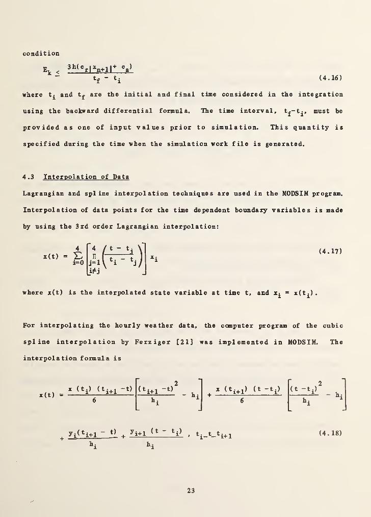
condition
Ev ^e,)
tf - t. (4.16)
where and t£ are the initial and final time considered in the integration
using the backward differential formula. The time interval, must be
provided as one of input values prior to simulation. This quantity is
specified during the time when the simulation work file is generated.
4 .3 Interpolation of Data
Lagrangian and spline interpolation techniques are used in the MODSIM program.
Interpolation of data points for the time dependent boundary variables is made
by using the 3rd order Lagrangian interpolation:
x(t)(4.17)
where z(t) is the interpolated state variable at time t, and = z(t£)
.
For interpolating the hourly weather data,
spline interpolation by Ferziger [21]
interpolation formula is
X (t.) (t£^.l -t)2
<‘i+l6
yi^^i+1 “ ^ ^i+1 *i^
the computer program of the cubic
was implemented in MODSIM. The
It •
I (t -tj)r 2
"
(t -t.)* h
6 i^i
» ^i-^-*i+l (4.18)
23

irhere = x(t£> for i=l, 2,...,n, and “ t^. The second derivatives
z"(t£) and i^2, 2 n~l are fonnd using the following set of
equations for the second derivatives of x(t) at nodes
20*1-1 +’>i) V'Ohi)
= 6^i+l ^i ^i ^i-1
$ 1“2
f
n 1
'i-1
(4.19)
The coefficients of these sets of equations from a tridiagonal matrix, and the
system can be solved for x" (t^), i=2,3 n-1 by using the Gaussian
elimination method.
Two additional equations are determined from the end conditions. Ferziger's
code uses the cantiler condition where
x"(tp = Xx"(t2 ) and x"(tj = Xx"(tj^_i), (4.20)
and Xe[0, 1]
.
In the MODSIM, 24 points of each component weather data (temperature,
pressure, etc.) are read once each day, and the second derivatives of the
variable are calculated using the set of equations as shown in equation
(4.19). At a given time during the day, the interpolated value is evaluated
using equation (4.20) with X « 1.
24
5. BUILDING LOADS CALCULATION
In HVACSIM'*’, a bnil ding shel 1 model and a bni 1 ding z one mode 1 are used for
building thermal loads determination. These models were developed based on
Kusnda [22] and Walton [9]. Previously the building shell model contained the
zone model [6]. In this report, these models are distinguished. Ihe building
shell model utilizes a user-sel ected fixed time interval, while the zone model
uses variable time intervals.
Models for building loads calculation include the effects of different kinds
of building shell materials, air temperatures, the moisture content of the
air, lighting, equipment, occupancy schedule, solar radiation, wind velocit>,
orientations of the exterior building surfaces, and the effect of shadowing.
Since there are so many factors involved, seme simplifying assumptions had to
be made. Ihe major assumptions in the current EVACSIK^ program include:
(1) Uniform temperature distributions on a building surface (one
dimensional heat transfer across a wall)
(2) Uniform ground temperature distribution
(3) No effects of wind direction, rain, and snow
The approach taken uses the standard response factor method to calculate the
conductive heat transfer rates through the building shell. The conduction
transfer functions are computed once and stored prior to a simulatior. The
same time interval i;sed in the calculation of conduction transfer functions of
building constructs is applied as the period during which the conductive heat
25

I
fluxes through the building surfaces are assumed to be invariant.
Primary routines for the building load determination are those dealing with
the calculation of building surface temperatures and zone loads. Walls and
zones are treated as component models, and are coded as TYPEn subroutines.
Because of the use of the fixed time step, the units representing building
surfaces must be in a superblock which is separate from those containing units
which use a variable time step.
The zone model calculates indoor air dry-bulb temperature and humidity ratio
on a variable time step basis and takes into account the dynamic operation of
the HVAC system and its controls, and thermal loads.
The building shell model contains three TYPE subroutines (TYPE50, TYPE51, and
TYPES3), and the building zone model is designated as TYPES2. In the
following sections, details of these TYPE subroutines are described.
26

S.l TYPE50: ZONE ENVELOPE
General Description
This subroutine combines information generated by the ITPE51 building surface
model. Convective beat gain from building surfaces and mean radiant
temperature are computed. Since this routine is a part of the building shell
model, it must be in a superblock which takes a user-selected, fixed time
step.
Nomenclature
2area of the j-th building wall surface (m )
*^is.c, jconvective heat transfer coefficient of the j-th building
inner surface (W/m^K)
^is.r.
j
radiative heat transfer coefficient of the j-th building inner
surface (W/m^K)
^sol.
j
total solar radiation influx (W/m )
Ns number of wall surfaces in a zone (-)
^sl.r short wave radiant heat flux from the sun and the lights (W/m )
^sw.r short wave (visible) radiant heat gain from lights (W)
^Iw.r long wave (infrared) radiant heat gain from people and
equipment (W)
^all convective heat flow rate from building surfaces in a zone (W)
Ti zone air dry-bulb temperature (C)
'^is.jsurface temperature of the j-th inner wall (C)
27

zone mean radiant temperature (C)
1 shading coefficient of the j-th building wall (-)c» j
Uisj
short wave absorptanoe of the j-th inner wall (-)
T 1 transmittance of the j-th wall (-)
Mathematical Description
Short wave radiant heat fluxes from the sun and the lights in a
evaluated by using the following expressions:
^sl.
Ns
A— 4^0 4 4 4^
s, J J sol y J SW 0 X
^®is,j 's.j>
Convective heat flow rate across the air film between the zone
interior surface of the building shell is given by
N,
^al 1 Sj=l
^is, c, j^s, j^^is, j- T.)
The expression of mean radiation temperature is obtained from
N.
E ^is,r,j\,jTis,j ^lw,r.1=1
^mr=
E^^is.r,j\.j
zone are
(5.1)
air and
(5.2)
(5.3)
28
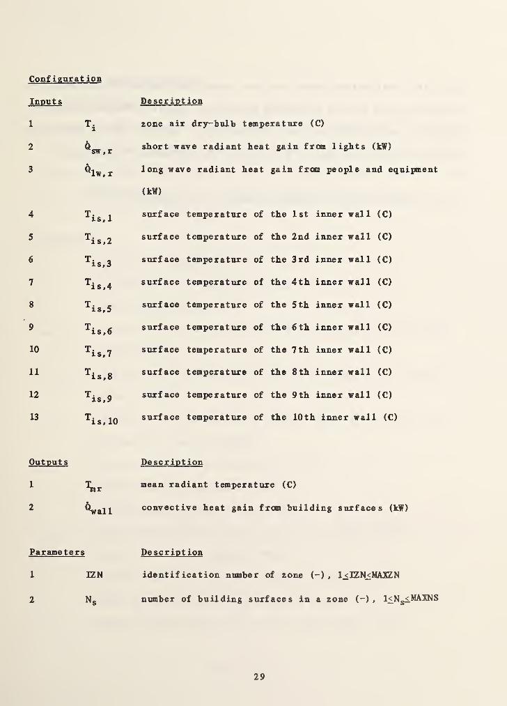
Configuration
Inputs
1
Description
zone air dry-bulb temperature (C)
2 Qsw, rshort wave radiant ]beat gain from lights (kW)
3 ^Iw, rlong wave radiant heat
(kW)
gain from people and eq
4 ^is, 1surface temperature of the 1 St inner wal 1 (C)
5 ^is,2 surface temperature of the 2nd inner wall (C)
6 ^is,3surface temperature of the 3rd inner wal 1 (C)
7 ^is,4 surface temperature of the 4th inner wall (C)
8 ^is,5 surface temperature of the 5 th inner wall (C)
9'*^is,6
surface temperature of the 6 th inner wall (C)
10'^is,7
surface temperature of the 7 th inner wall (C)
11 ^is,8 surface temperatxire of the 8 th inner wall (C)
12 ^is,9 surface temperature of the 9 th inner wall (C)
13"^is.lO
surface temperature of the 10th inner wall (C)
Outputs
\r
^all
Description
mean radiant temperature (C)
convective heat gain from building surfaces (kW)
Parameters Description
1 IZN identification number of zone (-) , l^IZN^MAIZN
2 Ng number of building surfaces in a zone (-) , l£Ng<.MAXNS
29

Note that variables which are not identified as inputs, outputs, or
parameters, but used in the TTPESO subroutine, appear in COMMON blocks. It
should be noted that the unit for heat flow rates is kW for inputs and
outputs, although the unit of W is used in the mathematical description.
In the current version of HVACSIM'*', MAXZN = 6, and MAXNS = 10.
30

5.2 TYPE51: BUILDING SURFACE
General Description
This subroutine computes outer and inner surface temperatures of a building
surface construct, and determines average solar flux on the outer surface.
Because this TYPES 1 subroutine is a part of the building shell model, it must
be in a superblock which takes a user-selected, fixed time interval.
Nomenclature
sg
ss
h.is,c,
j
*^is,r, j
os, J
sol, j
N,
Nt
^i, j ,n
angle factor between ground and surface (-)
angle factor between sky and surface (-)
ground reflectivity (-)
convective heat transfer coefficient of the j-th building inner
surface (W/m^K)
radiative heat transfer coefficient of the j-th building inner
surface (W/m^K)
convective plus radiative heat transfer coefficient of the j-th
building outer surface (W/m^K)
direct normal solar beam radiation (W/m^)
ground reflective radiation (W/m^)
total horizontal solar radiation (W/m^)
average solar radiation influx on the j-th surface (W/m )
diffuse (sky) solar radiation (W/m^)
order of conduction transfer function calculation (-)
number of conduction transfer function terms (-)
current conductive heat flux at the inner surface (W/m^)
31

•
^0, j,n2
current conductive heat flux at the outer surface (W/m )
‘I'iJ conductive heat flux at the inside of the j-th surface at the
present time due to past temperature history
^ o,jconductive heat flux at the outside of the j-th surface at the
present time (W/m^)
^sl,r short wave radiation heat flux from the sun and lights (W/m^)
•^sol, o, jsolar heat flux on the outside surface of the j-th construct (W/m )
flux term related to overall conductance (-)
Sd fraction of shadowed area to total exposed surface area (-)
Ti zone air dry-bulb temperature (C)
^is, jinside surface temperature of the j-th construct (C)
Tmr mean radiant temperature (C)
To outside air dry-bulb temperature (C)
Tqs,j
outside surface temperature of the j-th construct (C)
"j overall conductance (W/m^K)
Vw wind speed (m/s)
jX-component of conduction transfer function at the m time steps
ago (W/m^K)
>n, JY-component of conduction transfer function at the m time steps
ago (W/m^K)
jZ-component of conduction transfer function at the m time steps
ago (W/m^K)
^o.j X-component of conduction transfer function at the present time
(W/m^K)
32

Yo, j
Zo. j
“os, j
p
r
e
0
Y—component of conduction transfer function at th.e present time
(W/m^K)
Z-component of conduction transfer function at the present time
(W/m^K)
radiation absorptance of the j-th inner surface (-)
radiation absorptance of the j-th outer surface (-)
solar altitude angle (degrees)
tilt angle (degrees)
solar beam incident angle (degrees)
surface azimuth angle (degrees)
solar azimuth angle from south (degrees)
Mathematical Description
Conductive heat flow through a multilayered construct has been solved
successfully by the response factor method, in which the surface temperature
of each homogeneous layer is represented by a series of pulse functions.
Based on the response factor method, conduction transfer functions are
calculated for a multilayered wall. A heat balance at the j-th interior
surface is used to determine the interior surface temperature by [9]:
h. .T. + hi .T + Ui 1 d t + a' . 1 + Y .T ,
T, ,= i8,c,j 1 is,r,j^mr '*is,j ’*sl,r i,j *o,j*os,j _
is,j (5.4)h • • + h • 1 + Z 3is,c,j is,r,j ^o,j
The current conductive heat flux at the inner surface is
•^i.j.n ^o,j ^os,j ^o,j ^is,j (5.5)
33
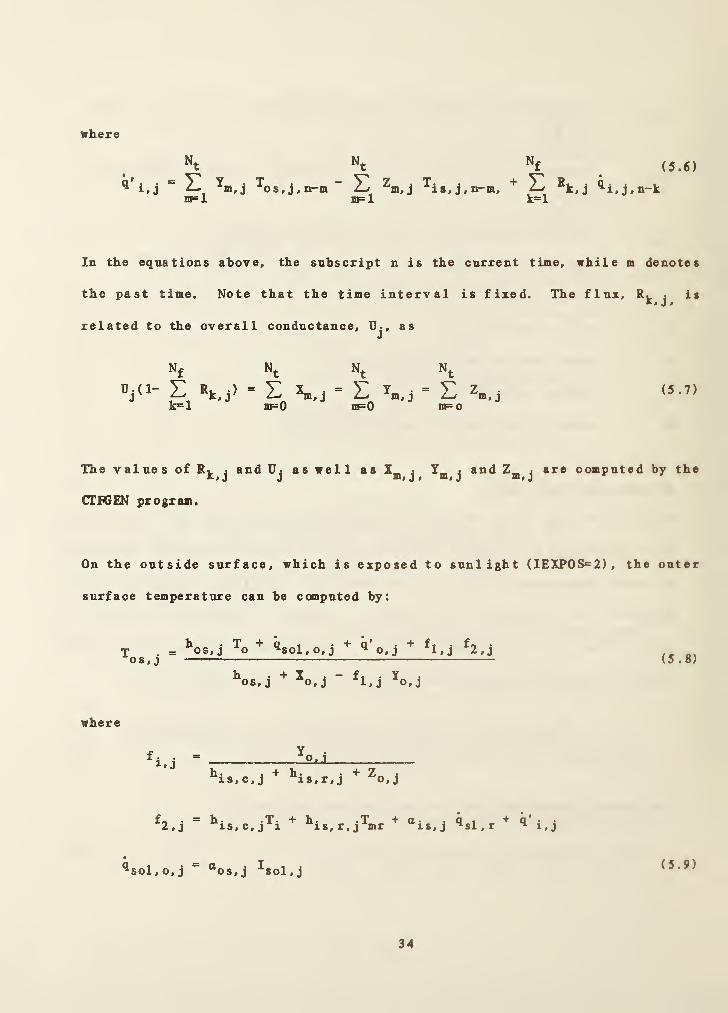
where
Nt Nt
^ ^os,j,nrm~ Sin=l nF=l
j
Nf
k=l
(5.6)
Rk,j ^i.j,n-k
In the equations above, the subscript n is the current time, while m denotes
the past time. Note that the time interval is fixed. The flux, R. > isX, j
,
related to the overall conductance, U-, as«l
N. N. N.
Ujd- L' k=i
»k,j)
't "t= L *m.j = 2
nF=0 IIF=0
m, j
"t
= Em=o
m, J(5.7)
The values of Rj^jand Uj as well as
j ^m J ^m jcomputed by the
(7IF6EN program.
On the outside surface, which is exposed to sunlight (IEXP0S<=2), the outer
surface temperature can be computed by:
T o soX^Ofj 2#jos,j (5.8)
^os,j ^o,j ^l,j ^o,j
where
J.O/j.
h • . + h • • Z — Jis,c,j is,r,j ^o,j
f« . = h* -T' + h- -T +ct- jQt2,j is,c,j 1 xs,r,j*mr is,j ^sl,r ** i.j
^sol,o,j “os,j ^sol,j (3.9)
34

The current conductive heat flux at the outer surface is
^o,j,n”
^o,j is,j j os,j ^ o, j(5.10)
where
N. N,’t "t
q' . = V Y i T. . - Y'
N.
m=l ai=l
’f (5.11)
^os,j,nrm, E ^k,j ^o,j,n-kk““l
Vhe n the outside surface is exposed to another zone or to ground (lEXPO^l),
the outside surface temperature is equal to the inside surface temperature in
another zone for the same construct or to the ground temperature (T._{=
'^'osinf ,
*
If a massive wall, which represents thermal mass, is within a zone (lEXPOS^O),
both the inside and the outside surface temperatures are considered to be
equal. The following expression can be used.
is, j ^os, j
^is,c,j^i ^is,r,j’*mr ^sl,r ^ i,j
*^is,c,j *^is,r,j ^o,j~
^o,j
(5.12)
Solar fluxes on the interior and exterior surfaces are evaluated based on
either solar data from a weather tape or computation. When a surface has a
surface azimuth angle, which is the angle from the south to the projection
of normal to the surface onto the horizontal plane in cloclcwise direction, and
a tilt angle, x, which is the angle between the normal to the surface and the
35
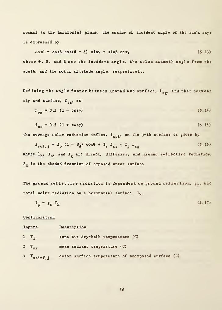
normal to tlie horizontal plane, the cosine of incident angle of the sun's rays
is expressed by
COS0 = cosp cos(0 - siny + sinp cosy (5.13)
where Cl, and ^ are the incident angle, the solar azimuth angle from the
south, and the solar altitude angle, respectively.
Defining the angle factor between ground and surface, f__, and that between5 g
sky and surface, f.., ass s
f-_ = 0.5 (1 - cosy) (5.14)
f__ = 0.5 (1 + cosy) (5.15)
the average solar radiation influx, on the j-th surface is given by
(5.16)
where I^, and are direct, diffusive, and ground reflective radiation,
is the shaded fraction of exposed outer surface.
^= Ik (1 - cosO + I, f.. + I„ f,„sol,j b d s 8s g sg
The ground reflective radiation is dependent on ground reflection, g^., and
total solar radiation on a horizontal surface, Ij^.
Ig'SrIh
Configuration
Inputs
1
2
3
Ti
mr
^osinf , j
Description
zone air dry-bulb temperature (C)
mean radiant temperature (C)
outer surface temperature of unexposed surface (C)
36

4 shaded fraction of exposed outer surface (-) , 0<.S^1
Outputs Description
1 T.IS, J
inner surface temperature (C)
^ ^sol,javerage solar radiation influx on the outer surface (W/m )
Parameters Descriptions
1 IZN identification number of zone (-) , 1^IZN_<MAXZN
2 j identification number of surface (-) , l^j^MAINS
3 lEXPOS 0 if the wall construct is inside the zone
1 if the wall construct is between zones or exposed to ground
2 if the wall construct is exposed to sunlight
4 ISTR identification number of construct (-) , l^ISTR^MAXSTR
' *s.j surface area (m^)
6 5 surface azimuth angle, measured from south to the projection of
normal to the surface onto the horizontal plane in clockwise
direction (degrees), 0±^<360
7 Y tilt angle of the surface, measured from the normal to
the surface to the normal to the horizontal plane (degrees),
OxY^lSO
Y = 0 for flat roof
Y = 180 for floor
8 gr ground reflectivity (-) , 0£gj,fl
9 IROFS outside surface roughness index (-) , l^IROFS_56
1 stucco
37

2 brick, rough plaster
3 concrete
4 clear pine
5 -— smooth plaster
6 glass, paint or pine
“os,j solar absorptance of the outer surface (-) , 0<a._ .<1QSfJ
“ “Is.j short wave absorptance of the inner surface (-) , 0<.O£g j<.l
12 8 .
•1
emissivity of the inner surface (-) , 0£8 ^£l
transmittance of the glass window (-) , 0<r_ ,<1
Tgj
= 0 for opaque wall
14 shading coefficient of glass window (-) , 0<S^<1
Sp = 0 for opaque wall
Note that variables which are not identified as inputs, outputs, or
parameters. but are used in the TTPESl subroutine, appear in (DMMON blocks.
In the current version of HVACSIM^, MAIZN = 6 , MAINS = 10. and MAXSTR » 10.
38

5.3 TYPES2; ZONE MODEL
General Description
In this TYPE52 subroutine, zone air temperature and humidity ratio are
computed based on zone loads. Most of the zone loads except convective heat
gain from building surfaces are internally determined in this subroutine. In
fact, this zone model belongs to the building shell model. However, the zone
model must be treated differently when the model definition file is created by
HVAOGEN because the zone model uses variable time steps.
Nomenclature
thermal capacitance of air (kJ/K)
effective thermal capacitance of furnishing (kJ/K)
Cp specific heat of zone air (kJ/kgK)
C_ _ specific heat of outdoor air (kJ/kgE)p# V
Cp^g
specific heat of supply air (kJ/kgS)
e^ air mass multiplier for moisture capacitance of zone (-)
fjj ratio of convective heat to total sensible heat from lights (-)
f^^ ratio of long wave radiative heat to total sensible heat from
lights (-)
fsw ratio of short wave radiative heat to total sensible heat
from lights (-)
hfg latent heat of vaporization of water (kJ/kg)
air exchange rate (1/h)
“infl mass flow rate due to infiltration (kg/s)
39
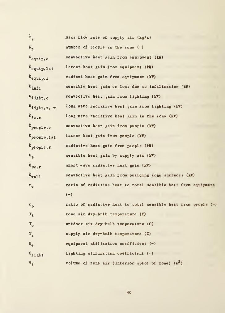
ms
mass flow rate of supply air (kg/s)
number of people in the zone (-)
^equip,
c
convective heat gain from equipment (kW)
^equip, lat latent heat gain from equipment (kW)
^equip,
r
radiant heat gain from equipment (kW)
^infl sensible heat gain or loss due to infiltration (kW)
^light, cconvective heat gain from lighting (kW)
flight, r, w long wave radiative heat gain from lighting (kW)
^Iw, r long wave radiative heat gain in the zone (kW)
^peopl e, cconvective heat gain from people (kW)
^pe ople, lat latent heat gain from people (kW)
^people, r radiative heat gain from people (kW)
sensible heat gain by supply air (kW)
•
Q̂sw, r short wave radiative heat gain (kW)
^all convective heat gain from building zone surfaces (kW)
ratio of radiative heat to total sensible heat from equipment
(-)
ratio of radiative heat to total sensible heat from people (-)
Ti zone air dry-bulb temperature (C)
To outdoor air dry-bulb temperature (C)
Ts supply air dry-bulb temperature (C)
Ue equipment utilization coefficient (-)
%ight lighting utilization coefficient (-)
Vi volume of zone air (interior space of zone) (n^)
40

^e, lat
%,iat
^p, s
Pi
Pinf 1
latent h.eat gain from equipment (kW)
sensible beat gain frc»n equipment (kW)
humidity ratio of zone air (-)
sensible heat gain from lights (kW)
humidity ratio of outside air (-)
latent heat gain from a person (kW)
sensible heat gain from a person (kW)
humidity ratio of supply air (-)
density of zone air (kg/m^)
density of infiltrated air (kg/m^)
Mathematical Description
Convective heat gains from people occupying the zone, from equipment such as
typewriters, computers, coffee pots, copying machine, etc. and from lights
are
:
^equip,
c
^light, c
=” - Wp.s= (1- V
^c^l ight^l ight
( 5 . 18 )
( 5 . 19 )
( 5 . 20 )
Latent heat gains from people and equipment are also considered, while
moisture absorptance and desorption by the building structure and interior
furnishings are not explicitly included in the building zone model.
people, lat~
^p^p, lat
^equip, lat =^e,lat
( 5 . 21 )
( 5 . 22 )
41
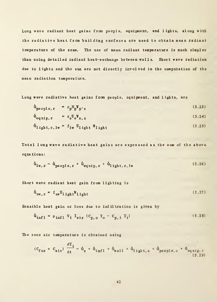
Long wave radiant heat gains from people, equipment, and lights, along with
the radiative heat from building surfaces are used to obtain mean radiant
temperature of the zone. The use of mean radiant temperature is much simpler
than using detailed radiant heat-exchange between wal 1 s. Short wave radiation
due to lights and the sun are not directly involved in the computation of the
mean radiation temperature.
Longwave radiative heat gains from people, equipment, and lights, are
Total longwave radiative heat gains are expressed as the sum of the above
equa tions
:
^ 1pe opl e , r
equip, r
(5.23)
(5.24)
(5.25)
(5.26)
Short wave radiant heat gain from lighting is
(5.27)
Sensible heat gain or loss due to infiltration is given by
(5.28)
The zone air temperature is obtained using
(5.29)
42

Heat flow rate from building surfaces is computed by the shell model (TYPES
0
and TYPES 1) .
The heat gain by supply air is expressed as
C mp, s s
(Tj - Ti) (5.30)
Zone air humidity is calculated from the zone air moisture balance equation.
In terms of humidity ratio, W, the moisture content of zone air is expressed.
p. V-1 ®m ^%eople,lat ^equip, lat^ ^^f g
+"infl <»o
-*i>
*"s <»s
-»i)
(5.31)
where h^^ is latent heat of vaporization of water, which can be obtained from
the fluid pr operty library, and e^^^ is an air mass mul tipi ier for moisture
capacitance of zone. Outdoor humidity ratio, W^, comes from weather data.
Configuration
Inputs
‘ ’i,*
2 T^
3
4 Ps.g
S m.
Description
gauge pressure of zone air (kPa)
zone air dry-bulb temperature (C)
humidity ratio of zone air (-)
gauge pressure of supply air (kPa)
mass flow rate of supply air (kg/s)
43

« Ts supply air dry-bulb temperature (C)
7 W3 humidity ratio of supply air (-)
® ^al 1convective heat flow rate from building surfaces (kW)
9 Np number of persons in the zone (-)
10 equipment utilization coefficient (-) , 0<D <1
11 l^light lighting utilization coefficient (-) , ®^^iight—
1
Outputs Description
1 Ti zone air dry-bulb temperature (C)
2 Wj humidity ratio of zone air (C)
^ ^sw,r shortwave (visible) radiant internal gain from lights
(kW)
^ ^Iw, rlong wave (thermal) radiant internal gain from people,
equipment, and lights (kW)
Parameters Descriptions
1 IZN identification number of zone (-) , l^IZhkMAlZN
2 fur effective thermal capacitance of furnishing (kJ/K)
3 ®m air mass multiplier for moisture capacitance of zone (-)
4 Vi volxone of zone air (interior space of zone) (m )
3 Is, air standard air exchange rate (1/h)
« Vs sensible heat gain from a person (kW)
’ Vi.t latent heat gain from a person (kW)
8 Wlight heat gain due to lighting in the zone (kV)
9 LIGHT type of lighting
44

1 for fluorescent lights
2 for incandescent lights
10 « sensible heat gain due to equipment (kW)e, s
11 1 . 4. latent heat gain due to equiinnent (kW)
12 r. ratio of radiative heat to total sensible heat frome
equipment (-) , 0 <r^<l
Note that the following constant values are assigned in the DATA statement in
the TYPE 52 subroutine:
rp = 0.7
for fluorescent lights, f^ = 0.6, fj^ = 0.2, and f^^ = 0.2
for incandescent lights, f^ = 0.1, fj^ = 0.8, and f^^ = 0.1
45
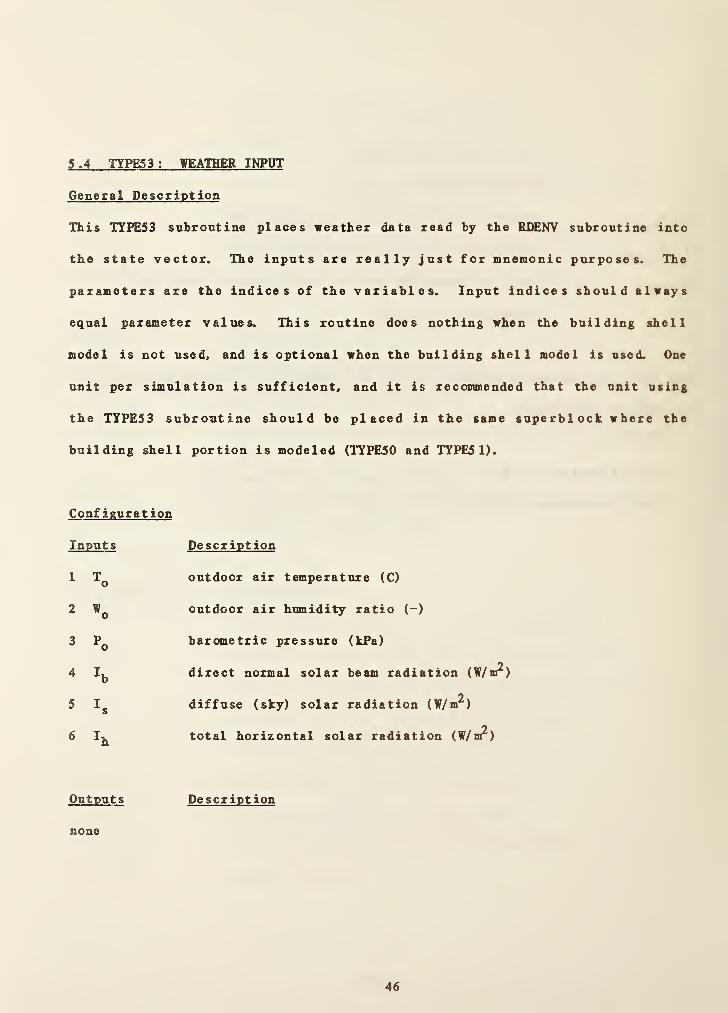
5.4 TYPES3: WEATHER INPUT
General Description
This TYJrti53 subroutine places weather data read by the RISNY subroutine into
the state vector. The inputs are really just for mnemonic purposes. The
parameters are the indices of the variables. Input indices should always
equal parameter values. This routine does nothing when the building shell
model is not used, and is optional when the building shell model is used. One
unit per simulation is sufficient, and it is recommended that the unit using
the TYPES3 subroutine should be placed in the same superblock where the
building shell portion is modeled (TTPE50 and TTPE51).
Configuration
Inputs
2
3 Po
4 Ib
5 Is
6 Ih
Description
outdoor air temperature (C)
outdoor air humidity ratio (-)
barometric pressure (kPa)
direct normal solar beam radiation (W/m^)
diffuse (sky) solar radiation (W/m^)
total horizontal solar radiation (W/n^)
Outputs Description
none
46

Parameters Description
1 NTOA index for To
2 NVOA index for Wo
3 NPOA index for Po
4 NDN index for h5 NSKY index for h6 NHOR index for If.
47
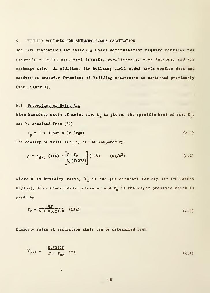
6 . UTILITY ROUTINES FOR BUILDING LOADS CALCULATION
The TYPE subroutines for building loads determination require routines for
property of moist air, heat transfer coefficients, view factors, and air
exchange rate. In addition, the building shell model needs weather data and
conduction transfer functions of building constructs as mentioned previously
(see Figure 1).
6 . 1 Properties of Moist Air
When humidity ratio of moist air, is given, the specific heat of air, C^,
can be obtained from [23]
Cp = 1 + 1.805 W (kJ/kgK) (6.1)
The density of moist air, p, can be computed by
P = Pdry <1+W) = P-PwR«(T+273). ® J
(1+W) ikg/v?) ( 6 . 2 )
where W is humidity ratio, R^ is the gas constant for dry air (^0.287055
kJ/kgK), P is atmospheric pressure, and P^ is the vapor pressure which is
given by
Pw =WP
W + 0.62198 (kPa) (6.3)
Humidity ratio at saturation state can be determined from
W0.62198
(-)sw
sat ~P - P (6.4)

where is saturated vapor pressure (kPa) and can be computed by [24]
sw = 3 .376 EXP 15.463 -,
L 1.8T + 424 (kPa)(6.5)
Hie function CP contains the expressions for moist air.
6 .2 Air Exchange Rate
The air exchange rate is calculated using wind speed, and the dry-bulb
temperature difference between indoor and outdoor air [25].
lair "^s,air (0.013) (2.2369) + (0.005) ( 1.8) IT^, - T^|]/0.695
( 6 . 6 )
where I. _• and are standard air exchange rate (1/h), and wind speed (m/s)S > & X 7 w
respectively. Standard air exchange can be chosen one of the following
V al ue s
:
Living space - 1.5 for leaky building
1.0 for standard building
0.5 for moderately tight building
Attic space - 20.0 for mechanical ventilation
6.0 for natural ventilation
Crawl space - 3.0
The air exchange rate expression is in the (H* function.
6 .3 MRT View Factors
Radiation exchange between zone surfaces is obtained by using the mean radiant
temperature network (NRTN) method introduced by Carroll [26]. Surfaces
interact with a mean radiant temperature instead of directly with each other.
49

Because of it, the nxunber of interactions is reduced from n^ to n. The MRT
network method includes a factor called 'MRT view factor' which is expressed
by
1
j “ _ ^s»j ' j~l»2,...,Ng
N,
E
(6.7)
2where A • is the j-th surface area (m ), and N_ is the number of surfaces in5 j J 5
the zone. This equation is solved iteratively. Maximum number of iterations
is assigned to be 100 in DATA statement of the VIEW subroutine. The
subroutine VIEW was written to compute the view factors based on the TARP
package. The VIEW subroutine is called at the beginning of simulation, and
the calculated view factors are stored for succeeding computations.
6 .4 Heat Transfer Coefficients
The convective heat transfer coefficient of the j-th inner surface is obtained
from one of the following expressions [9]:
0.333
_ 9.482 I '^i - ^is. i I
^is,c,j " 7.238 -I Cosy I if T-^ Tj (6.8)
0.333
_ 1.810 I ^i - ’’^is.l I
“is,c,j ~ 1.382 + I Cosy I if j< (6.9)
50

where y denotes the tilt angle of the surface from horizontal plane. The unit
of heat transfer coefficients is watts/n^K.
Using view factors of surf ace s which enclose the zone (see equation (6.7)),
the radiant heat transfer coefficients are computed. For the j-th surface,
the coefficient is
is,r,j = 4o(Tt,)+ 273)
_1 + l-«j
F. T-
J J
( 6 . 10 )
where a is Stephan-Bol tzmann's constant (=5.670X10"’^watts/n?K^) , Fi the view•I
factor, and Cj the emissivity.
The convective plus radiative heat transfer coefficient, h__ , is given in aVSp J
simple expression as a function of wind speed, V^(m/s).
h . = a + a,V + a„ (6.11)os,j o 1 w 2 w
in which a^, a^^, and ^2 are coefficients which can be determined by the
surface roughness index. Walton provided the values of these coefficients
with respect to roughness index in his TARP reference manual [9]. The wind
speed is the reported value without modification for surface height or
orientation.
51

IROFS ^2
1 11.58 5.894 0.0
2 12.49 4.065 0.028
3 10.79 4.192 0.0
4 8.23 4.000 -0.057
5 10.22 3.100 0.0
6 8.23 3.330 -0.036
The function HISCF contains expressions for heat transfer coefficients.
52

7. CONDUCTION TRANSFER FUNCTION CALCULATION
Conduction transfer functions of walls, floors, roofs, and windows are
required by the TYPES 1 subroutine for a building shell modeling. The
subroutine also needs a term related to conductive heat fluxes on both
external and internal surfaces of constructs. The CTFGEN program calculates
the conduction transfer functions and the flux transfer functions. In this
section, the overview of CTFGEN and the methodology employed in CTFGEN for
computing conduction transfer functions will be described.
7 . 1 Overview of CTFGEN
The CTFGEN program consists of two portions: the front end and the main
routines. In the front end portion, inputs and output operations are handled,
and in the main routine, conduction transfer functions and flux transfer
functions are determined. Thermal properties of building materials
(thickness, thermal conductivity, density, specific heat, and thermal
resistance) are stored in a sequential access data file (IHERM.DAT). By using
CTFGEN, thermal properties of additional building materials can be added in
the data file. User selected building materials can be composed to form a
multilayered building construct (sometimes called construction), after
selecting necessary thermal property data from a temporary, direct access
file, which contains the same information in the sequential access file.
The main calculation routine was originated from TARP, (slightly modified from
BLAST) and its calculation procedure is as follows:
53

( 1) Determine tlie upper and lower bounds for searching roots (poles) for
residue calculation and determine the roots (SEARCH)
(2) Calculate derivative matrices and total construct matrices, and
obtain residue elements for nonrzero poles (DER, MATRIX)
(3) Calculate zero residue elements (ZERORE)
(4) Compute response factors and determine high order conduction
transfer functions (RFCOMP)
(5) Check convergence. If not converged, reduce the increment for
searching and go to step (1)
(6) Calculate flux transfer functions
Since a discussion of the calculation procedure involves a lengthy
mathematical description, only important expressions will be reviewed in this
report. Further detailed information may be found in references [27, 28].
7 .2 Heat Conduction of a Multilayered Construct
Equation for heat conduction for a one-dimensional heat flow in a homogeneous
layer of building material is given by
a^T(x.t) _ dT(x.t) (7.1)
2 Px-^
where T(x, t) is the temperature k, p,
density, and specific heat, respectively.
q(x, t) = - k —dx
and C^ are thermal conductivity.
The heat flux through the slab is
(7.2)
54

Assuming that k, p, and are constant and T(x,0)=0, and applying Laplace
transform on the above equations, ordinary differential equations in terms of
X and Laplace parameter s are obtained.
d^T(x. s)
dx2
and
- T(x.s)
q(x, s) ^ dT(x.s)
dz
(7.3)
(7.4)
where a is thermal diffusivity defined by k/pC^. Imposing boundary conditions
on equations (7.3) and (7.4) such that
Tj(s) = T(o,s), T2(s) = T(S,,s), q^(s) = q(0,s), and q2 (s) = q(S,,s), where
I is the thickness of the construct, a matrix expression is obtained.
r—
Tj(s) = A(s) B(s) T2(s)
qi(s) C(s) D(s) _q2(s)_
where A(s) = cosh (J2^v^)
B(s) “ ^sinh ()iv^
C(s) = k /| sinh (2,»^)
D(s) = cosh (Hv^)
(7.5)
Since a multilayered construct also has the same form of transfer matrix
55

(transmission matrix) as the singl e- 1 ay ered construct, the total construct
matrix for n layers becomes
A(s) B(s) Aj^ ( s ) ( s
)
\(s) B^U)'
C(s) D(s) q(s) Dj^(s)
a • •
C„(.) D„(s)
Equations (7.5) and (7.6) are coded in the subroutine MATRIX.
When the j-th layer of a multilayered construct has very low thermal
capacitance, the transfer matrix of the j-th layer yields
1 im
C.-^o*1
Aj(s) Bj(s)
Cj(s) Dj(s)
H.-J.
(7.7)
Heat flux equations on the outer (j=l) and inner (j=n+l) surfaces of the
multilayered construct can be expressed as
qo(s) DLsIB(s)
1
B(s)To(s)
1
•H
1
1
B(s)_ ALsl
B(s)
T^(s)
where T^j(s) = Tj(s) and T^(s) =
With the sign convention for heat fluxes in the TARP program, the heat f 1 as
leaving the surface has a positive sense, as shown in Figure 6. Using this
convention, equation (7.8) can be rewritten as
56

^2 ^n-1
Figure 6. A multilayer construct
57

(7.9)
%is)B(s)
1
B(s)T„(s)
qi(s)
L .
1
B(s)_ Aj.s.)
B(s)Ti(s)
Heat flux equations in the time domain can be obtained by applying the
inversion theorem of the Laplace transform to equation (7.9).
7.3 Response Factors
Assuming that the boundary temperature functions, T^(t) and T^(t), can be
represented by a series of pulse functions with a uniform time interval,
equation (7.9) can be written as
r-m ™
qo(s) _ 1
B(s) B(s)= P(s)
qi(s) 1 _ ALsI Ti,t-m<">B(s) B(s)
-
where m=0 , 1 ,2 ,... ,®, and P(s) is a pulse function in Laplace transform. The
subscript t-m denotes the past time lagging m6 from the current time. The
variable 8 is sample time.
If the pulse function is represented by a triangular pulse with base of 26 and
unit height, and if response factors are defined as follows:
external response factor: P(s)B(s)
5 8
hfO ,1,2...(7.11)

cross response factor: iif0,1,2 . . .
(7.12)Ym = L
-1P(s)
B(s)
internal response factor: Zj^ = L-1
P(s)B(s)
df=0,1,2 (7.13)
then the heat fluxes can expressed in terms of response factors.
00
mF=0
«li(t) L
(7.14)
Kusuda [27] and Hittle [28] described well the procedure for computing
response factors in detail.
The general formula for inverting a Laplace transformed expression q(s) based
on Cauchy's residue theorem is given by
q( t) = —
^
q(s)e®^ ds =51 Res(aj) (7.15)
where t is time, and a. is the j-th pole which is a root determined by setting«l
the denominator of q(s)e®^ to be zero, i.e, B(s)=0.
A modified false position method is implemented for finding roots of an
algebraic equation, and coded in the ILLINI subroutine. Improved root search
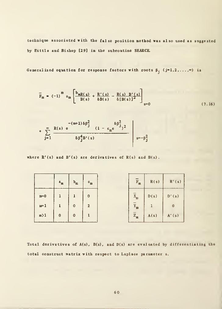
technique associated with the false position method was also used as suggested
by Hittle and Bishop [29] in the subroutine SEARCH.
Generalized equation for response factors with roots Pj ( j=l,2 , . . . ,®) is
Fmm
(-1) a„ ^mR( s)
B(s)+ R*( s) _ R(s) B* (s)
6B(s) 6[B(s)]^s=0 (7.16)
® R(s) e
" E
-(m*-l)8p? 8p?(1 - c^e
j=l 6pjB'(s)
where R'(s) and B'(s) are derivatives of R(s) and B(s).
^m m ®m
nF=0 1 1 0
mp 1 1 0 2
m>l 0 0 1
Fm R(s) R'(s)
D(s) D'(s)
1 0m
Zm A(s) A'(s)
Total derivatives of A(s), B(s), and D(s) are evaluated by differentiating the
total construct matrix with respect to Laplace parameter s.
60

(7.17)
A'(s) B'(s) A(s) B(s)
^ d
ds
C'(s) D'(s) C(s) D(s)
The subroutine DER computes the derivatives and the residue for non-zero
poles, , which is shown as the second term of equation (7.16). A portion
of zero residue (s=0) is calculated in the ZERORE subroutine, and its result
is combined with that by the DER subroutine to form equation (7.16) in the
subroutine RF(X)MP.
An important property of response factors is
CO 00 00
LkOF=0 hfO nF=0
(7.18)
where U is the overall conductance represented by
U =n ^i n (7.19)
r^ is the thermal resistance of the i-th layer.
7 .4 Conduction Transfer Functions
As seen in equation (7.16), response factors when m>l have the same form.
^m " S (7.20)
j=l
61

where Xj-8P^ .
e j and g.R(s) (1 - e^Pj)^
6p]B'(s)s= -pi
The subscript j is the index of the roots of B(s)=0, all of which are located
on the negative real axis.
Based on equation (7.20), conduction transfer functions (CTF) are defined such
that for j-th order
( 7 . 21 )
( 7 . 22 )
F- = FJ,o ^o
F- — F• 1 _ X" F- 1 1j,m j-l,m J j-l,m-l
For internal, cross, and external conduction transfer functions, F< _ isJ »®
replaced by X- , Y- , andZj _, respectively. Calculation of high orderJ#*** J#™
conduction transfer functions continues starting from the first order (j>>l)
until the following condition is met:
I 1 -I <e (m=l, 2 ,. .), ( 7 . 23 )
where
H
k
1 = 1
k,ffl
u n (i-x.)
j=l^
and e is a small number.
When the convergence condition is satisfied, the resulting order is k. In
62
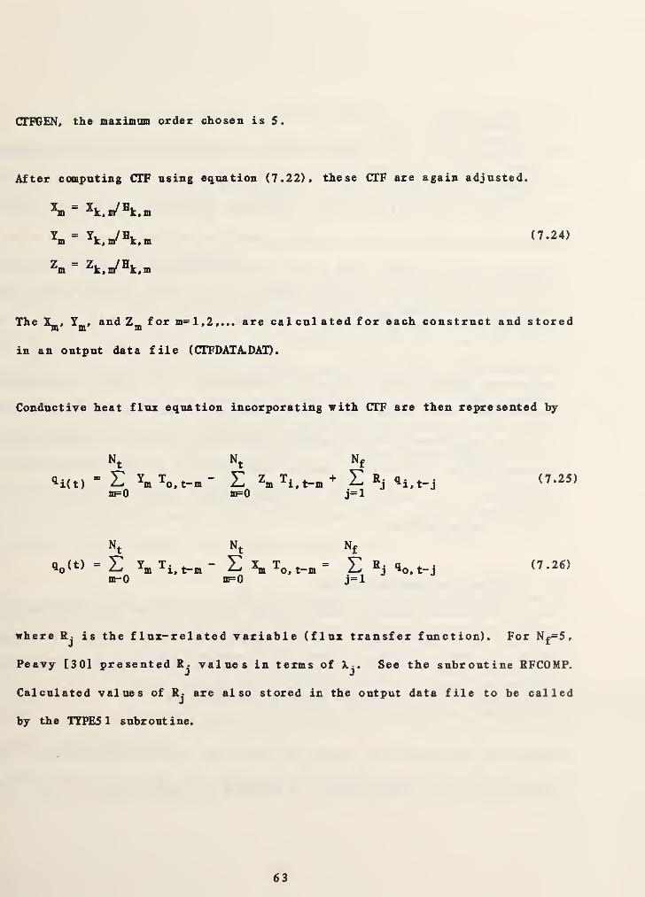
CTF6EN, the maximim order chosen is 5.
After computing CTF using equation (7.22), these CIF are again adjusted.
^ n/®k, m
Z_ — Zt. _/ Ht. _m x,m x,m
The and Zji^ for m=l,2,... are calculated for each construct and stored
in an output data file (CTFDATA.DAD
.
Conductive heat flux equation incorporating with CTF are then represented by
^i(t)
Nt
EnF=0
N N,
Y Tm o, t-m
t
X] ^m ^i , t-mBF=0 j=l
R. ^i, t-j (7.25)
qo<t)
Nt
Em-0
m ^i, t-m
Nt Nf
^ ^ ^o, t-m ”^o, t-j
m=0 j=l(7.26)
where Rj is the flux-related variable (flux transfer function). For N£=S,
Peavy [30] presented R- values in terms of k,. See the subroutine RFCOMP.J J
Calculated values of R- are also stored in the output data file to be called*1
by the TYPES 1 subroutine.
63

8 . WEATHER DATA
When a simulation involves building thermal loads, weather data are required
by MODSIM, Tbe subroutine RDENV in MODSIM expects to read outside air dry-
bulb temperature, humidity ratio, barometric pressure, wind speed, direct
normal solar beam radiation, sky diffuse radiation, and total horizontal solar
radiation for each hour. The hourly weather data are interpolated for a
fraction of an hour by using the spline interpolating routine which was
explained in the section 4.3.
The program RETAFE reads a weather tape (see Figure 1) and writes the selected
weather data on an output data file (WTPOUT.DAT). The weather data in the
file are transformed into the proper input format required by RDENV by the
program CRWDTA. If a weather tape or equivalent is not available or some
information from a weather tape is missing, CRWDTA generates artificial data
to fill missing portions.
8. 1 Weather Tape Reading Routine
The program RDTAFE requires inputs for the type of weather tape, the weather
station identification nnmber, and the beginning and ending dates of selected
weather information. The conventional data is converted into Jul ian day and
positioning a tape is performed based on the Julian day.
Since, for simplicity, the effects of rain, snow, and wind direction are not
considered in the current version of HVACSIM"^* subroutines for reading
64
tapes were simpl if ied accordingly. RDTAPE is capable to read f our kinds of
tapes: 'NOAA SOLMET/ 'NOAA Typical Meteorological Year (TMY) . ' 'NOAA Te s
t
Reference Year (TRY),' and 'Weather Year for Energy Calculation (WYEC),'
tapes. Host of the subroutines in RDTAPE are based on BLAST [3 1] and TARP.
8.2 Weather Data File Generation
The program CRWDTA allows several options. It can read the output of RDTAPE
and rewrite the information in the format required by RDENV, dividing total
horizontal solar radiation values into beam and diffuse components if
necessary. Alternatively, it can generate smooth 'design day' solar radiation
and temperature data for a clear or cloudy sky design day. The latitude,
longitude, and time zone data must be entered at the beginning of data file
generation by CRWDTA. The output data file of CRWDTA (WEATHER.DAT) contains
month, day, hour, dry-bulb temperature (C), humidity ratio (-), barometric
pressure (kPa), wind speed (m/s), direct beam solar radiation (W/m ), sky
2 2diffusive radiation (W/m ), and total horizontal radiation (W/m ).
If information on direct beam or sky diffuse radiation is missing from a
weather tape (e.g., WYEC tape), the direct and diffuse radiation values are
computed by the subroutine WTPINP in the CRWDTA program. In order to use the
correlation, equation of time, E, declination angle, 8, extraterrestrial
normal radiation intensity, are calculated using equations presented by
Duffie and Beckman [32].
^ = h: 19.87 sin(2B) - 7.53 cos(B) - 1.5 sin(B)] (h) (8.1)
65

8 = 23.45 sin [2n(284+n)/365] (degrees) ( 8 . 2 )
®o,n" [1+0.033 cos (2nn/365)] (W/m^) (8.3)
where B = 2n(n-81)/364
n is the day of year, l_<n^365
Sunrise time, t^^., and sunset time, t^^, are
= {Lm -
y15
t = /long _I 15
In the above equation, LONG is longitude angle in degrees, and u>^ sunset hour
angle given by
(Dg = cos ^ [- tan(L) tan(8) ] (8.6)
where L is latitude angle in degrees. Time zone number, TZN, in the United
States for standard time is 4 = Atlantic, 5 = Eastern, 6 Central, 7
Mountain, or 8 = Pacific.
When total horizontal radiation, is zero, direct beam and diffuse
radiation values are also zero. The following discussion refers only to hours
>)-TZNI - E +
IZNl - E +
(8.4)
(8.5)
66

with non^zero I
Since solar radiation data are generally integrated energy or average power
over a period of an hour, the program uses the solar hour angle half an hohr
ago to represent the average solar position for the hour. Exceptions occur
for the two hours each day which include sunrise or sunset. In the se case s,
only time interval after sunrise and before sunset is considered. Denoting
and (1)2 as solar hour angle at the beginning time and the ending time,
respectively, for the i-th hour of the day, these hour angle expressions are
The cosine of the solar zenith angle, Z, is calculated using the average of
and (1)2 •
Extraterrestrial horizontal radiation, I^, is a time averaged value for an
hour from to 0)2 •
wi = ^ [max(ti_i t--) - 12 + E + TZN] 2- LONG1 12 11, sr jgQ
(8.7)
( 8 . 8 )
cos(Z) = sin(6) sin(L) +cos(6) cos(L) cos[ (o)^ + a>2)/2] (8.9)
67

( 8 . 10 )Iq = ^ Gq^ n^cos(L) cos(5) [ sin((D2 )- sin((oi) ] +((D2“U)i) sin(L) sin(8)
If direct beam radiation, is known and diffuse radiation, I^, is missing,
tbe value of is obtained from
Is = Ih - I|,cos(Z) (8.11)
If I^ is known while I^^ is not given, I^ is computed from
Ib = (Ih - Is)/cos(Z) (8.12)
When both I^ and I|^ are unknown, the estimation of I^ is made using the
hourly diffuse correlation of Erbs, Uein, and Duffie [33].
I
I
^ = 1.0 - 0.09 kj for 0<kx<0.22h
= 0.9511 - 0.1604 k.j. + 4.388 k| ~ 16.638 k^ 12.336 kl}.
for 0.22 <kj<0.80
(8.13)
= 0.165 for 0.80<kj.a.0
where kj. is the hourly clearness index given by
kj=Vlo (8.U)
68

With Ig obtained by equation (8.13), is calculated using equation (8.12).
The weather tapes mentioned previously do not give humidity ratio but dew
point temperature. The humidity ratio is determined using the dew point
temperature. Refer to section 6.1 and the function WF.
The program CRWDTA generates smooth artificial design day weather data if a
weather tape or equivalent data file is not available. Clear or cloudy sky
design day data can be created after entering input data: initial day and
month, number of days for which weather calculation will be made, barometric
pressure, wind speed, relative humidity, minimum and maximum dry-bulb
temperature s.
To create cloudy sky design day data (ISFLAG =3), a fixed value of daily
clearness index, k^., must be given. With this kj, hourly clearness index, kj,
at the i-th hour of day can be calculated from the following relation:
(8.15)
where a = 0.409 + 0.5016 sin(ta)^ - tt / 3 )
b = 0.6609 - 0.4767 sin(Wg - tt/3)
Total horizontal radiation, Ij^, is then obtained
^h ~ ^^o (8.16)
69

Knowing equations (8.11) and (8.12) give the values of and I^. See the
subroutine SCK.AR.
Clear sky design day data (ISFLAG=2) is generated by the subroutine SOLAR in
CRWDTA. CRWDTA hnplonents all three methods presented by Machler and Iqbal
[34]. The method used by the program depends upon user's responses to
questions asked when clear sky data generation is requested. Horizontal
visibility, geographic correction factor, and precipitable water are involved.
Method 1 is the simplest method, which is a modification of the ASHRAE clear
sl^ irradiation algorithm. When horizontal visibility is zero, the method 1
is used.
where A^^, and are apparent solar constant, exponential attenuation
coefficient, and diffuse fraction factor, respectively. These are sets of
twelve constants, one for each month. Machler and Iqbal presented modified
values of Aj^, Bj^, and Cj^. The variable o is defined by
h = ^A (8.16)
(8. 17)
a <P/Po)/cos(Z) (8. 18)
7 0

in which P, and Z are barometric pressure, standard atmospheric pressure
(=101.3kPa) and zenith angle, respectively.
The correction factor for regional variation, k^, is 'clearness number' listed
in ASHRAE Handbook (e.g., 1981 Fundamentals, p. 27.8) [35].
Method 2 uses horizontal visibility at ground level as a parameter of
atmospheric turbidity. If horizontal visibility is not zero, but precipitable
atmospheric moisture is zero, the method 2 is used.
^b" ®o,n "^a
(0.775)^^®-^^ (8.19)
I3 = (0.1 + 0.3/VIS) (8.20)
where f(x) is defined by o* (i.e., f(0.5) = a®*^) , VIS is horizontal visibility
at ground level in km, and t^
is atmospheric transmittance.
Tg = (1 - 1.13 (8.2 1)
Method 3 is applied to modify the equation for I|^, if a non-zero value for
precipitable water is given.
Ib = Tg (0.775)^^®*^^ (1.0223 - 0.00149M) (8.22)
where M is the precipitable water in mm.
71

Approximated dry-bulb temperature calculation is made using empirical values
shown in the table of ASHRAE Handbook [35] for summertime. For the ir-thhour,
Ti = Tmai ’‘^max
‘Tmin> Oi/WO
where ^min' ^i design day maximum, minimum temperatures, and
percentage of the daily range as empirical values. This temperature
calculation is coded in the subroutine DB. Note that equation (8.23) is not
valid for wintertime. Calculation procedure for wintertime temperature has
not been implemented in CRWDTA.
Assuming constant relative humidity for a day, hourly humidity ratio is
computed using the expressions in ASHRAE Handbook p. 6.4. The subroutine
HUMIDT determines the hour 1 y humidity ratio.

9. SIMULATION PROCEDURE
Generally, a computer simulation using HVACSIM+ involves three steps:
preprocessing, simulation, and postprocessing.
9.1 Preprocessing - Input Data Generation
(1) Creation of Simulation Work File
The building load and the system component portions are considered as
separate parts. The type description file (TYPAR.DAT) must be accessible
by both HVA06EN and SLIHOON. See the Reference Manual [7] and the Users
Guide [8] for details.
Building Load Ccxnponent Portion
( i) Draw a sketch of the building to be simulated and divide the
building shell into a number of zones as necessary.
(ii) Make block diagrams for the building load components and assign a
UNIT number to each component along with the proper TYIR number.
(iii) Fill out all the required information on the worksheets, which are
appended in APPENDIX B, for the building load components: TYPE50,
TYPE51, TYPE52, and TYPE53.
( iv) Execute the HVAOGEN program. During the execution, enter necessary
data which was prepared on the worksheets. Note that one of
SUPERBLOCKS is reserved only for the zone envelope (TYPE50), the
building surface (TYPE51), and the weather input (TYPE53). Zone
73
models (TTFE52) should reside in the other SUFEKBLOCK or SUPERBLOCKS
which may also contain the system component models.
System Component Portion
( i) Draw a sketch of the building system to be simulated.
( ii) Make block diagrams for system components which serve the zones, and
assign a UNIT number to each component with a proper TYPE number,
(iii) Fill out all the required information on the worksheets, which are
appended in APPENDIX in reference [8], for the system components.
( iv) Execute the HVACGEN program. Enter necessary information and edit
the simulation work file if needed.
(2) Creation of Model Definition File
After creating the simulation work file, the SLIMOON program can generate
the model definition file (MODELDEF.DAT) for the MODSIM program from the
simulation work file. Since it is very difficult to make any changes in
the model definition file, any changes should be made in the simolatlon
work file instead.
(3) Creation of Boundary Variable File
Any explicitly defined, indexed input or output variables in TYPEn
subroutines can be boundary variables.
( i) Edit the simulation work file to declare the boundary variables
using the HVACGEN program.
(ii) Make a boundary data file (BOUNDARY.DAT) using a user's editing
program. The first column of the boundary variabe data file must
74

contain values of time (Time intervals need not be equal). For step
changes, two sequential records should be entered having the same
value of time but different values of a boundary variable.
(4) Creation of Conduction Transfer Function File
( i) Find out what kind materials are used to form the building envelope
element ( wall, roof, ceiling, floor, partition, or window).
( ii) Search the thermal property data bank of building materials
(IHERM.DAT) whether required data are available. If not, obtain
thermal property data from other sources.
(iii) Execute the CTFGEN program interactively to add thermal property
data and/or obtain conduction transfer functions of the specific
constructs. When a construct has very low thermal capacitance
(Cp?%iO), the value of thermal resistance must be specified. The
output file of CTFGEN ( CTFDATA. DAT) will be used by the RDENV
subroutine of the MODSIM program.
(5) Creation of Weather Data File
( i) Execute the RDTAFE program interactively to read weather information
from a weather tape or equivalent.
( ii) Using the output file of the RDTAPE program (WTPOUT.DAT), execute
the CRffDTA program to create the weather data file (WEATHER.DAT) for
the subroutine RICNV of the MODSIM program. If no weather tape data
is accessible or for simplicity it is not desired to use a weather
tape for simplicity, an artificial weather data file can be
generated by the CRWDTA program.

9.2 Siaulation
(1) Allocation of Output Files
The output files of the MODSIM program, MODSUM.DAT, MODOUT.DAT. and
1NIT0UT.DAT, are automatically allocated on the computer disk storage
spaces by the Fortran?? OPEN statements in the MODSIM.
(2) Execution of MODSIM
A simulation is performed by MODSIM using previously created data files.
During the execution, some of the data can be monitored on the screen of
a computer terminal. With the building model, a simulation involves tvo
steps of execution. The first step is the initialization run for
temperature and flux histories for computation of conductive heat
transfer rates for a given period of time, usually 24 hours. The second
step is the actual simulation.
(3) Continuation of Simulation
At the end of each run of MODSIM for a given period, the output file,
1NIT0UT.DAT, is created. This file has all of the data which are needed
to continue the simulation at the next time period. However, INITODT.DAT
must be renamed as INITIN.DAT before the next, continuing simulation is
begun. Otherwise no continuation of the simulation is made.
9 .3 Postprocessing - Output Data Analysis
Execution of the SORTSB program produces a sorted data file for a
specific SDPERBLOCK from the MODOUT.DAT file. This step is necessary to
generate an input file for a user- suppl ied plotting routine, if moro that
one SUPE^LOCK is associated.
10 . REFERENCES
[1] Klein, S.A., et al., 'TRNSYS, A Transient System Simulation Program,'
Report 38-12, University of Wisconsin, Dec. 1983.
[2] Kelly, G.E., Park, C. , Clark, D.R., and May, W.B., 'HVACSIM^, A Dynamic
Bail ding/ BYAC/ Control Systems Simulation Program,' Proc. of Workshop on
HVAC Controls Modeling and Simulation, Georgia Inst, of Tech., Atlanta,
GA, Feb. 2-3, 1984.
[3] Hill, C.R., 'Simulation Techniques for Building Systems,' Proc. of
Workshop on HVAC Controls Modeling and Simulation, Georgia Inst, of
Tech., Atlanta, GA, Feb. 2-3, 1984.
[4] Hill, C.R., 'Simulation of a Multizone Air Handler,' ASHRAE Trans., Vol.
91, Part 1, 1985.
[5] Clark, D.R., Hurley, C.W., and Hill, C.R., 'Dynamic Models for HVAC
System Components,' ASHRAE Trans. Vol. 91, Part 1, 1985.
[6] Park, C. , Clark, D.R., and Kelly, G.E. , 'An Overview of HVACSIM'*’, A
Dynamic Building/ HVAC/Control Systems Simulation Program,' the 1st Annual
Building Energy Simulation Conference, Seattle, WA, August 21-22, 1985.
[7] Clark, D.R., 'HVACSIM^ Building Systems and Equipment Simulation Program
Reference Manual,' NBSIR 84-2996, National Bureau of Standards, Jan.
1985.
[8] Clark, D.R., and May, W.B., Jr., 'HVACSIM^ Building Systems and Equipment
Simulation Program Users Guide,' NBSIR 85-3243, National Bureau of
Standards, Sept. 1985.
77

[9] Walton, G.R, 'Thermal Analysis Research Program Reference Manual,' NBSIR
83-2655, National Bureau of Standards, March 1983.
[10] NBS 'Guide to Available Mathematical Software (GAMS),' Center for
Applied Math., National Bureau of Standards, Oct. 1981
[11] Hiebert, K.L., 'An Evaluation of Mathematical Software that Solves
Systems of Nonlinear Equations,' ACM Trans. Math. Software, Vol. 8, No.
1, March 1982, pp. 5-20.
[12] Powell, M.J.D., 'A Hybr id Me thod f or Nonl ine ar Equa t ions, ' in Numer ica 1
Methods for Nonl inear A1 gebraic Equations , P. Rabinowitz, Ed., Gordon and
Breach, London, 1970.
[13] Broyden, C.G., 'A Class of Methods for Sol v ing Nonl inear Simultaneous
Equations,' Math. Comp., Vol. 19, 1965, pp. 577-5 93 .
[14] Ral ston, A. and Rabinowitz, P. , A First Course in Numerica l Ana l ysis.
McGraw-Hill, 1978.
[15] Dennis, J.E. and Schnabel, R.B., Numerica l Method s for Uncons tra ined
Optimization and Nonl inear Equations . Prentice-Hall, 1983.
[16] Fox, P.A., Hal 1, A.D., and Schryer, N.L., 'Algorithm 528 Framework for a
Portable Library [Z],' ACM Trans, on Math. Software, Vol. 4 , No. 2, June
1978, pp. 177-188.
[17] Brayton, R.K., Gustavson, F.G., and Hachtel, G.D., 'A New Efficient
Algorithm for Solving Differential - Algebraic Systems Using Implicit
Backward Differential Formulas,' Proc. IEEE, Vol. 60, No. 1, Jan. 1 97 2,
pp. 98-108.
[18] Gear, C.W., 'The Automatic Integration of Ordinary Differential
Equations,' Comm. ACM, Vol. 14, March 1971, pp. 176-179.

[19] Nordsieck, A., 'On Numerical Integration of Ordinary Differential
Equations,' Math. Comp., Vol. 16, 1962, pp. 22-49.
[20] Chua, L.O., and Lin, P., Computer-Aided Analysis of Electronic Circuits,
Prentice-Hall, 1975.
[21] Ferziger, J.H., Numerica l Methods for Engineering App l ication . John
Wiley, 1981.
[22] Eusuda, T., '^6SLD, The Computer Program for Heating and Cooling Loads in
Building,' BSS 69, National Bureau of Standards, July 1976.
[23] Threlekld, J.L. , Therma 1 Env ironmenta l Engineering , 2nd ed,, Prentice-
Hall, 1970.
[24] Brokaw, R. S. , 'Calculation of Flue Losses for High-Efficiency Furnaces
and Appliances,' ASHRAE J. , Jan. 1979, pp. 49-51.
[25] Eusuda, T. and Saitch, T. , 'Simplified Analysis Calculations for
Residential Applications,' NBSIR 80-1961, National Bureau of Standards,
July 1980.
[26] Carroll, J. A., 'A Comparison of Radiant Interchange Algorithms,'
ASME/ SSEA Conf. , April 1981.
[27] Eusuda, T. , 'Thermal Response Factors for Multilayer Structures of
Various Heat Conduction Systems,' ASHRAE Trans., Vol. 75, 1969, pp. 246-
270.
[28] Hittle, D.C, 'Calculating Building Heating and Cooling Loads Using the
Frequency Response of Multilayered Slabs,' Report CERL-TM-E- 169,
Construction Engineering Research Lab, 1981.

[29] Hittle, D.C., and Bishop, R., 'An Improved Root-Finding Procedure for Use
in Calculating Transient Heat Flow Through Multilayered Slabs/ Int. J.
Heat and Mass Transfer, Vol. 26, No. 11, 1983 , pp. 16 85-16 93 .
[30] Peavy, B.A., 'A Note on Response Factors and Conduction Transfer
Functions,' ASHRAE Trans., Vol. 84, 1978, pp. 688-690.
[31] Hittle, D.C., 'The Building Loads Analysis and System Thermodynamics
(BLAST) Program, Version 2.0: User Manual,' Tech. Rep. E-153,
Construction Engineering Research Laboratory, 1979.
[32] Duffie, J.A. and Beckman, W.A., Sol ar Engineering of Therma l Processes .
John Wiley, 1980.
[33] Erbs, D.G., Klein, S.A., and Duffie, J.A., 'Estimation of Diffuse
Radiation Fraction for Hourly, Daily, and Monthly Average Global
Radiation,' Solar Energy Laboratory, University of Wisconsin, Madison,
1981.
[34] Machler, M.A., and Iqbal, M. 'A Modification of the ASHRAE Clear Sky
Irradiation Model,' ASHRAE Trans. Vol. 91, 1985.
[35] ASHRAE, 1981 Fundamentals Handbook . ASHRAE, 1981.
80

APPENDIX A: Short Descriptions of Ftmctions and Subroutines in HVACSIM+
(1) Primary Program of HVACSIJU-
* Main Program
( File : M0DSIM5 )
MODSIM - Modular simulation program
* Input /Output
( File : M0DIN05 )
BLOCK DATA - Assignment of logical unit numbers to files, setting numericalvalues of typical properties of air and water, and givinglabel names
BOUNDS - Reading of time-dependent boundary variables, andinterpolating them using the 3rd order Lagrangian interpolation
INDATA - Entering input data for a simulation on the console
OPNFIL - Opening of input and output files
ROONF - Reading of the model definition and the initialization files
REPORT - Generation of the report file at equal intervals
SUMARY - Writing of a sinnmary of configurtion of simulation
VLAB - Returning labels and numbers
* Block and State Variable Status Control
( File : M0DBLK5 )
ASEMBL - Assembling of BLOCK inputs and outputs
BACTIV - Control of BLOCK activity
FRZVAR - Variable freezing
INPUTS - Assignment of state variables to inputs of UNIT
INSCAN - Scanning the inputs of SUPERBLOCKs to detect changes largerthan the error tolerance
81

INTLIZ Initialization of the simulation
ODTPDT - Storing of outputs from UNIT
RESTAT - Resetting of outputs of a BLOCK for unfrozen variables
UNFREZ - Checking for frozen variables
* Integration of Stiff Ordinary Differential Equations
( File : M0DBDF5 )
BAKDIF - Calculation of derivatives using backward difference formulars
CALN - Computation of the minimum time step
ECNTRL - Calculation of truncation errors and determination of time
step and integration order
IPERM - Permutation of vectors
NORDER - Increasing or decreasing the order of integration
PREDIK - Calculation of predicted values for the next time step
RESET - Resetting the differential equation integrator
SAVECO - Saving and replacing coefficients
UPDATE - Updating coefficients for BAKDIF and PREDIK
Routines needed for Solving a System of Equations
File : M0DEQT5 )
BLOCK - Calculation of a new state vector by calling a BLOCK
FNC - Calculation of the residual functions for a BLOCK
SUPERB - Calculation of a new state vector by calling a SUPERBLOCK
SUPFNC - Calculation of the residual functions for a SUPERBLOCK
( File : SELECTS )
SELECT - Calling TTFEn subtoutines
* Nonlinear Algebraic Equation Solver
( File : SNSQA )
82

SNSQ
SNSQl
SNSQ2
( File :
DOGLEG
ENORM
QFORM
QRFAC
RIMPYQ
RIUPDT
( File :
FDJACl
FDJAC2
RIMACH
* Models
( File :
TYPEl
TYPE2
TYPES
TYPE4
TYPES
TYPE6
TYPE?
TYPES
- Finding a zero of a system of nonlinear functions
- The same as SNSQ but called by the BLOCK subroutine
- The abbreviated version of SNSQ
SNSQB )
- Determination of the convex combination x of the Gauss-Newtonand scaled gradient directions
- Calculation of the Euclidean norm of x
- Accumulation of orthogonal matrix Q frcmi the computed QRfactorization
- QR factorization of a matrix using Householder transformations
- Computation of A*Q for a given matrix A
- Determination of an orthogonal matrix Q
SNSQC )
- A forward difference approximation to the Jacobian matrix.Called by SNSQ.
- The same as FDJACl except argument. Called by SNSQl and SNSQ2
.
- Machine-dependent constants for the local computer environment
of HVAC Components and Controls
TYPES )
- Fan and pump model
- Conduit (duct or pipe)
- Inlet conduit (duct or pipe)
- Flow merge
- Damper or valve
- Flow split
- Temperature sensor
- Proportional- Integral controller
83

TYPE9 - Linear valve with pneumatic actuator
TYPEIO - Hot water coil model
TYPEll - Hot water to air heating coil
TYPE12 - Cooling or dehumidifying coil
TYPE13 - Three-way valve model
TYPE14 - Evaporative humidifier
TYPE15 - Rocmi model with constant zone loads
TYPE16 - Sticky proportional controller
TYPE17 - Mixing dampers and merge
TYPE18 - Plenum
TYPE19 - Flow balance control
TYPE20 - High/low limit controller
TYPE21 - Clamped split
TYPE22 - Steam spray humidifier
TYPE23 - Steam nozzle
TYPE24 - Ideal gas nozzle
TYPE25 - Steam to air heating coil
TYPE26 - Control signal inverter
TTPE27 - Moist air flow merge
TYPE28 - Constant flow resistance
TYPE29 - Inlet constant flow resistance
* Building Loads Model ccmponents
( File : TYPESB )
TYPES
0
- Zone envelope (Building Shell)
TYPE51 - Building surface (Building Shell)
TYPES 2 - Zone model
84
TYPES
3
- Weather input (Building Shell)
• Supporting Utility for System Components
( File ; UTILITY )
HYSTER - Hysterisis of actuators
DELAY - Transport delays in ducting components
SUFED - Coefficients for the polynomial of the efficiency of heat
exchanger fin
BESI - Modified Bessel function
BESE - E Bessel function
POLFIT - Polynomial fitting
* Supporting Utility for Building Load Components
( File : UTILITYB )
CP - Specific heat of moist air, vapor pressure, air exchange rate,
and humidity ratio at saturated state
HISCF - Computation of convective heat transfer coefficient of the
inner surface to the zone air, convective plus radiative heattransfer coefficient of the outer surface, and radiative heattransfer coefficient of the inner surface
VIEW - View factors using MRT network method
( File : RDENV )
RDENV - Reading of weather data and conduction transfer functions.Interpolation of hourly data using the spline interpolation.
SILINE - The second derivatives for the spline interpolation
SPEVAL - Interpolation by using the cubic spline method
* Steam and Liquid Water Properties
( File :: WATPR )
TSATS - Saturation temperature of steam vs. pressure
PSATS - Saturation pressure of steam vs. temperature
85

VSATS - Saturation specific volume of steam vs. temperature andpressTire
VSATW - Saturation specific volume of water vs. saturation temperature
HSATff - Saturation enthalpy of liquid water vs. saturation temperature
HFG - Latent heat of vaporization of water vs. saturationtemperature
HSATS - Enthalpy of saturated steam vs. saturation temperature
SSATW - Saturation entropy of liquid water vs. saturationtemperature
SSATS - Entropy of saturated steam vs. saturation temperature
VS - Specific volume of superheated steam vs. pressure andtemperature
HS - Enthalpy of superheated steam vs. pressure and temperature
SS - Entropy of superheated steam vs. pressure and temperature
TPSS - Temperature of steam vs. pressure and entropy
CPS - Specific heat of steam at constant pressure vs. temperature
CVS - Specific heat of steam at constant volume vs. specific voliaie
and temperature
VISSV - Dynamic viscosity of saturated vapor vs. pressure
VISSPH - Dynamic viscosity of superheated steam vs. temperature
STEAME - Thermal conductivity of superheated steam vs. temperature
WREO - Density of water vs. temperature
WMD - Viscosity of water vs. temperature
WE - Thermal conductivity vs. temperature
WCP - Specific heat of water vs. temperature
Air Properties
( File : AIRPR )
CPCVA - Specific heats of air at constant pressure and volume, and
speed of sound in air
86
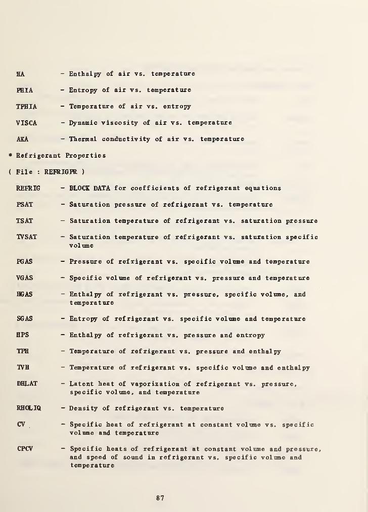
HA - Enthalpy of air vs. temperature
PHIA - Entropy of air vs. temperature
TPHIA - Temperature of air vs. entropy
VISCA - Dynamic viscosity of air vs. temperature
AKA - Thermal conductivity of air vs. temperature
• Refrigerant Properties
( File : REFRIGPR )
REFRIG - BLOCK DATA for coefficients of refrigerant equations
PSAT - Saturation pressure of refrigerant vs. temperature
TSAT - Saturation temperature of refrigerant vs. saturation pressure
IVSAT - Saturation temperature of refrigerant vs. saturation specificvolume
EGAS - Pressure of refrigerant vs. specific volume and temperature
VGAS - Specific volume of refrigerant vs. pressure and temperature
BGAS - Enthalpy of refrigerant vs. pressure, specific volume, andtemperature
SGAS - Entropy of refrigerant vs. specific volume and temperature
HPS - Enthalpy of refrigerant vs. pressure and entropy
TPH - Temperature of refrigerant vs. pressure and enthalpy
TVH - Temperature of refrigerant vs. specific volume and enthalpy
DHLAT - Latent heat of vaporization of refrigerant vs. pressure,specific volume, and temperature
RHOLIQ - Density of refrigerant vs. temperature
CV - Specific heat of refrigerant at constant volume vs. specificvolume and temperature
CPCV - Specific heats of refrigerant at constant voliune and pressure,and speed of sound in refrigerant vs. specific volume andtemperature
87

(2) Conduction Transfer Function Calculation
( File : CTFGEN )
CTF - Main program to create the CTF data file (CTFDATA.DAT)
IHERMP - Adding new data of thermal properties of building materialsin the thermal property data file (THERM.DAT)
BANKTP - Making a temporary direct access file of the thermal propertydata
DER - Calculation of the total construct and total derivativematrices, and determination of residue elements for a non-zeroroot
DUMPRF - Printing description of conductive layers, values of roots,
conduction transfer functions, and flux transfer functions
ERROR - Printing error messages
ILLINI - Computation of roots in the interval using modified false
position method
INITRF - Calling subroutines related to calculation of conductiontransfer functions
MATRIX - Evaluation of the conduction matrix for a multilayered slab
RCOMP - Computation of conduction transfer and flux transfer functionsfor multilayered constructs
SEARCH - Determination of the upper and lower bounds within which a
root must exist.
ZERORE - Calculation of zero residue elements
(3) Weather Data
* Weather Tape Reading
( File : RDTAPE )
RDTAPE - Main program to read weather tapes
RDWTP - Positioning and checking weather tapes
RDSOLM - Reading of a NOAA SOLMET tape
RDTMY - Reading of a NOAA Typical Meteorological Year (TMY) tape
88

RDTRY Reading of a NOAA Test Reference Year (TRY) tape
RDWYEC Reading of Weather Year for Energy Calculations (WYEC) tape
WRTFIL Writing output data (WTPOUT.DAT)
JDS Evaluation of Julian date
* Weather Data File Generation
( File : CHWDTA )
CRWDTA Main program to create the weather data file
WTPINP Reading the output file of the RDTAPE program and computationof solar radiation data which are missed in the weather tape
WF Humidity ratio vs. dew point temperature and pressure
SOLAR Generation of artificial weather data of solar radiation
DB Design day outdoor air dry-bulb temperature for summer
HUMIDY Humidity ratio assuming constant relative humidity
COPYFL Writing outputs on the weather data file (WEA1HER.DAT)
(4) Front-End Program for Handling a Simulation Work File
* Main Module
( File : HVACGENl )
HVACGE Main program of the HVAOGEN program
INFORM BLOCK DATA containing the types of data and COMiK)N BLOCKinformation
DATAIN Verification of input information
COPMOD Input data processor
CHECK Checking whether the parsed word is a number
REflGRD Checking whether the input is reserved word
REMAIN Control of transfer to the requested module
HOLDIT Producing a pause for acknowledgment of error display
89

SCROLL Making a screen display paused when the screen is full
OKAY Checking whether an existing value is acceptable
RITE Displaying of console messages and menu
PROMPT Providing the index labels corresponding to category numbers
* Create Module
(File ; HVACGEN2 )
CREATE Control of transfer to the proper routine for create mode
CRUNIT Creating a UNIT to be used in a work file
CRBLK Creating a BLOCK to be used in a work file
CRSUP Creating a SUPERBLOCK to be used in a work file
CRSIM Calling CRSIMl. CRSIM2. CRSIM3. and CRSIM4 for SIMULATION setup
CRSIMl Entering the simulation title, and error tolerances
CRSIM2 Entering initial values of state variables
CRSIM3 Entering boundary information
CRSIM4 Entering the information of reported variables
RECRT Calling a proper module according to the entry of reservedwords (ABORT. HELP, VIEW, EDIT, and TYPES )
TYPES Listing the TYPEs avaiable in the TYPAR.DAT file
* File Control Modtile
File : HVA0GEN3 )
FSAVE Calling the routine for saving the created file for UNIT,
BLOCK, SUPERBLOCK, or SIMULATION setup
READIN Selecting the module for reading a file based on the file
extension
OPNFIL Entering the file name and opening the file
RDUNT Reading the file of UNIT with the extention UNT
RDBLK Reading the file of BLOCK with the extension BLK
90

RDSIM Reading the file of SIMULATION setup with the extension SIM
SAVUNT Writing information to the UNIT file
SAVBLK Writing information to the BLOCK file
SAVSOP Writing information to the SUPERBLOCE file
SAVSIM Writing information to the SIMULATION file
TYFEIN
* View Module
Creating a direct access file for TYPAR.DAT at the first call,
and reading the information from the direct access file.
( File : HVA03EN4 )
VIEW Control of transfer to the proper routine for view mode
VEWUNT Viewing the inputs, outputs, and parameters for the UNIT
VEWBLK Viewing the information for the BLOCK
VEWSIM Providing the menu for different view options
SIRUCT Viewing of the structure of the SIMULATION setup
VARVAL Viewing of the initial values of state variables for inputs in
the SIMULATION
BOUND Viewing of the boundary information for the SIMULATION
RPTVAR Viewing of the reported variables in the SIMULATION
ERROR Viewing of the error tolerances, and the freezing and scanoptions in the SIMULATION
REVEW Directing to either HELP or ABORT mode
VEWALL Viewing of all information in the SIMULATION
* Edit and Help Module
( File : HVA0GEN5 )
EDIT Control of transfer to the proper routine for edit mode
EDUNT Editing the information in the UNIT
EDSIM Editing the information in the SIMULATION
91

EDTITL - Editing the title
EDSTR - Calling the routines for editing the structure
EDVAL - Editing the initial values of state variables
EDBND - Calling the routines for editing the boundary information
INSERT - Entering the index of a boundary variable to the SIMULATION
DELETE - Deleting the index of a boundary variable from the SIMULATION
EDREP - Calling the routines for editing the information of reportedvariables
PRCHNG - Editing the reporting interval
RPINRT - Entering the index of a reported variable to the SIMULATION
RPDELT - Deleting the index of a reported variable from the SIMULATION
EDERR - Editing the error tolerances and the freezing and scan options
REEDT - Calling the help module
REEDIT - Calling the help module (similar to REEDT)
File : HVACGEN6 )
INSSIM - Calling the routine for inserting or replacing UNIT or BLOCK
INSUNT - Inserting a UNIT in the SIMULATION
INSCHK - Giving the number of UNITs in the BLOCK
INSBLK - Inserting a BLOCK in the SIMULATICM^
INCK2 - Giving the information of SUFERBLOCK and UNIT to the snbrootlne
INSBLK
RECALC - Recalculation of the new position of the variables in the
state vector after an insertion
TYPINF - Getting information of the input and output category indeces
from the TYPAR.DAT file
REBND - Calculation of the new position in the state vector of the
boundary variables
REREPT - Calculation of the new position in the state vector of the
reported variables
92

DEL SIM - Calling the routine for deleting a UNIT or BLOCE from a
SIMDLATION
DELUNT - Deleting a UNIT from the SIMULATION setup
DELBLE - Deleting a BLOCE from the SIMULATION setup
DELCHE - Checking the UNIT number to be deleted
DELCE2 - Checking the BLOCE number to be deleted
REPSIM - Calling the routine for replacing a UNIT in the SIUMULATION
REPDNT - Replacing a UNIT in the SIMDLATION
HELP - Description of available commands in the HVA06EN program
EXIBLE - Saving the information in the BLOCE of the SIMDLATION file
in a BLOCE f ile
(5) Model Definition File Generation
(File : SLIMOON )
SIMCON - Main program of the SLIMOON program to generate a model
definition file (MODELDEF.DAT) using a simulation work filewith the extension SIM
FILEOP - Opening the input and output files
TYPAR - Getting information from the TYPAR, DAT file
REP(®T - Displaying the configuration parameters along with the maximumvalues assigned
VARCHE - Checking whether any of the time-dependent boundary variablesare solved simultaneously
OUTCHE - Checking if two or more outputs are assigned to a single state
variable
TDBVIS - Finding the largest number of time-dependent boundary variablesin any one SDPERBLOCE
(6) Sorting the Raw Data File
( File : SORTSB )
SORTSB - Program to sort the raw output data file (MODOUT.DAT) for
each SDPERBLOCE to create a data file which can be used as aninput data file to a user- suppl ied plotting routine
93

APPENDIX B: Worksheets for Data Entry for TYPE 50, 51, 52, and 53
*************A***«(******************t********A****)t********************
TYPE 50 ZONE ENVELOPE UNIT=
INPUTS
;
TIA: Zone air dry-bulb temperature (C) T
QISV: Internal (short wave) radiant gain from I i ght
s
( kV) --Q
QILW: Internal (long wave) radiant gain (kW) Q
TIS(l); Inner surface temperature (C) T
TIS(2); Inner surface temperature (C) T
TIS(3); Inner surface temperature (C) T
TIS(4): Inner surface temperature (C) T
TIS(5); Inner surface temperature (C) T
TIS(6): Inner surface temperature (C) T
TIS(7): Inner surface temperature (C) T
TIS(8): Inner surface temperature (C) T
TIS(9): Inner surface temperature (C) T
TIS(IO): Inner surface temperature (C) T
OUTPUTS
:
TMR : Mean radiant temperature (C) T
QWALL; Convective heat gain from building surfaces (kV) Q
PARAMETERS;1 IZN: Identification number of rone
2 NS; Number of surfaces of tone
NOTE; When the number of surfaces is less than 10, an indei of
the last surface may be used for the remaining temperature
input s
.
94
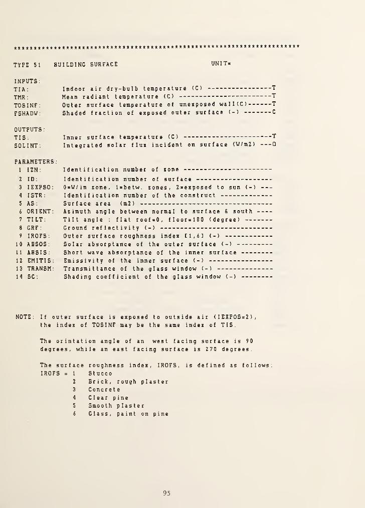
TYPE 51 BUILDING SURFACE UNIT=
INPUTS
;
TIA;
TMR;
TOSINF
;
FSHADW:
Indoor air dry-bulb temperature (C) T
Mean radiant temperature (C) T
Outer surface temperature of unenposed wa 1 1 ( C ) T
Shaded fraction of exposed outer surface (-) C
OUTPUTS
:
TIS ;
SOLINT;
Inner surface temperature (C) T
Integrated solar flux incident on surface (V/m2) Q
PARAMETERS
;
1 IZN:
2 ID:
3 lEXPSO;
4 ISTR;
5 AS;
6 ORIENT;7 TILT;
8 GRF
9 IROFS:
10 ABSOS;
11 ABSIS;
12 EMITIS;13 TRANSM:14 SC;
Identification number of xone
Identification number of surface0=W/in lone, l=betw. zones, 2=exposed to sun (-)
Identification number of the constructSurface area (m2)
Azimuth angle between normal to surface & southTilt angle flat roof=0, floor=180 (degree)
Ground reflectivity (-)
Outer surface roughness index [1,6] (-)
Solar absorptance of the outer surface (-)
Short wave absorptance of the inner surfaceEmissivity of the inner surface (-)
Transmittance of the glass window (-)
Shading coefficient of the glass window (-)
NOTE. If outer surface is exposed to outside air (IEXPOS=2),the index of TOSINF may be the same index of TIS
The orintation angle of an west facing surface is 90
degrees, while an east facing surface is 270 degrees.
The surface roughness index, IROFS,
IROFS = 1 Stucco2 Brick, rough plaster3 Concrete4 Clear pine
5 Smoot h plaster6 Glass, paint on pine
is defined as follows;
95
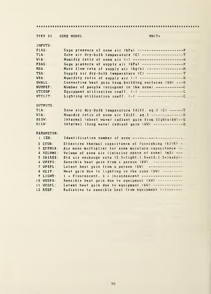
**************** * * *****************************************************
INPUTS
:
PIAG: Gage pressure of rone air (kPa) P
TIA: Zone air dry-bulb temperature (C) TVIA: Humidiy ratio of zone air (-) H
PSAG : Gage pressure of supply air (kPa) P
MSA: Mass flow rate of supply air (kg/s) M
TSA : Supply air dry-bulb temperature <C) TWSA : Humidity ratio of supply air (-) H
QVALL: Convective heat gain from building surfaces (kV) Q
NUMPEP: Number of people (occupant in the zone) C
UTCEQP: Equipment utilization coeff. (-) C
UTCLIT; Lighting utilization coeff. (-) C
OUTPUTS
:
TIA: Zone air dry-bulb temperature Idiff. eq . ] (C) TVIA: Humidiy ratio of zone air tdiff. eq . ] H
QISV: Internal (short wave) radiant gain from 1 i gh t s ( kV ) - -Q
QILV: Internal (long wave) radiant gain (kV) Q
PARAMETER:1 IZN: Identification number of zone
2 CFUR: Effective thermal capacitance of furnishing (kJ/K) -
3 EFFMIA: Air mass multiplier for zone moisture capacitance --
4 VOLUME: Volume of zone air (interior space of zone) (m3)
5 SAIREX: Std air ezchange rate ( 0 . 5 = t i gh t , 1 . 0 = s t d , 1 5 = 1 e ak y )
-
6 VPEPS: Sensible heat gain from a person (kV)
7 VPEPL: Latent heat gain from a person (kV)
8 VLIT: Heat gain due to lighting in the zone (kV)
9 LIGHT: 1 = Fluorescent, 2 = Incandescent10 VEQPS: Sensible heat gain due to equipment (kV)
11 VEQPL : Latent heat gain due to equipment (kV)
12 REQP: Radiative to sensible heat from equipment (-)
96
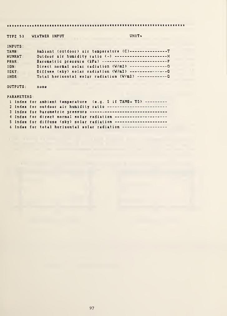
TYPE 53 WEATHER INPUT UNIT=
INPUTS;
TAMB : Ambient (outdoor) air temperature (C) T
HUMRAT: Outdoor air humidity ratio (-) H
PEAR; Barometric pressure (IcPa) P
IDN; Direct normal solar radiation (V/m2) Q
ISKY; Diffuse (sky) solar radiation (V/m2) Q
IHOR: Total horisontal solar radiation (V/m2) Q
OUTPUTS; none
PARAMETERS;1 IndeK for ambient temperature (e.g. 5 if TAMB= T5 )
2 IndeK for outdoor air humidity ratio
3 Indea for barometric pressure4 Index for direct normal solar radiation5 Index for diffuse (sky) solar radiation6 Index for total horixontal solar radiation
97

APPENDIX C: Etample 1 One-xone Building Model
A single-xone building model is simulated in this example, following the
Simulation Procedure outlined in Chapter 9 of this report. The purpose of theexample is to demonstrate how to use HVACSIH-t' with the building loads modeldescribed in this reportfsee Figure 1). No system component is connected to
the tone and no boundary variable is considered. Artificially generatedweather data is used. Screen images of I/O operation during the executionsof programs and all related data files are presented.Different results from the outputs of this example are anticipated when a
computer with different values of machine precisions from those used in this
example. See the function RIMACH in the file SNSQC
.
The machine precisions used are:
RlMACH(l) = 5.3976E-79RIMACH<2) = 7.2370E+75R1MACH(3) = 5.9605E-8R1MACH(4) = 9.5367E-7
A . Preprocessing - Input Data Generation( 1 ) Creation of Simulation Work File
As shown in Figure C-1, the example model is an office module located on a
floor (other than the top or ground floor) of a multi-story building The
building surfaces faced to the south are exposed to the sun. while othersurfaces are unexposed, interior surfaces.
Figure C-2 is a simplified block diagram which shows the input-outputconnections of UNITS. Since UNIT 9 (Weather Input) has no direct connectionto any UNIT, it is not shown here.
98

T91
151
T9
west wall^^0
T2 T6
East wall
Floor T3
T9
North wall
South window
T8 T7
1 South wall
I
1T9 r 11 T9
VIEW FROM THE SOUTH VIEW FROM THE EAST
Figure C-1. A single-zone model
99
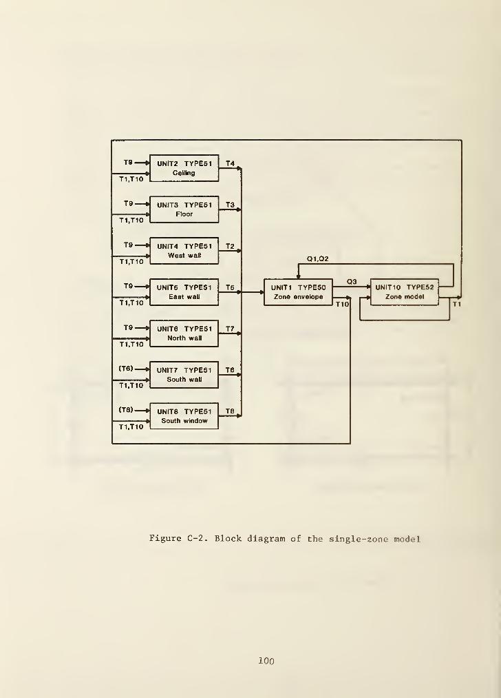
Figure C-2. Block diagram of the single-zone model
100

* Vorkshcetf
TYPE 50 ZONE ENVELOPE UN1T= /
INPUTS:
TIA: Zone air dry-balb temperature (C) T/QISV: Internal (short wave) radiant gain from 1 i ght s ( kV) --Q
/
QILW: Internal (long wave) radiant gain (kW) QjL
TIS(l): Inner surface temperature (C) T2.
TIS(2): Inner surface temperature (C) t3TIS(3): Inner surface temperature (C) T^TIS(4): Inner surface temperature (C) TTTIS(5): Inner surface temperature (C) T^TIS( 6 ): Inner surface temperature (C) TyTIS(7): Inner surface temperature (C) T^TIS( 8 ): Inner surface temperature (C)
TIS(9): Inner surface temperature (C) TS*-
TIS(IO): Inner surface temperature (C) T^
OUTPUTS
:
TMR: Mean radiant temperature (C) t /O
QVALL: Convective heat gain from building surfaces (kV) Q3
PARAMETERS:1 IZN: Identification number of sone /
2 NS: Number of surfaces of tone -7
NOTE: When the number of surfaces is less than 10, an indei of
the last surface may be used for the remaining temperatureinputs
.
101

***t****»***»t«*««**»<l***»****»*******«******************»***»***»******
TYPE 51
INPUTS.
TIA;
TMR;
TOSINF
:
FSHADW:
BUILDING SURFACE UNIT= X
Indoor air dry-bulb temperature (C) T /
Mean radiant temperature <C) T /i?
Outer surface temperature of uneiposed wa 1 1 ( C ) TfShaded fraction of eiposed outer surface (-) C
OUTPUTS
:
TIS: Inner surface temperature (C) T
SOLINT: Integrated solar flui incident on surface (V/m2) Q C?
PARAMETERS
:
1 IZN: Identification number of «one /
2 ID; Identification number of surface /
3 lEXPSO: 0=V/in tone, Isbetw. tones, Zcoiposed to sun (-) i
4 ISTR: Identification number of the construct I
5 AS; Surface area (m2) J7. a-1
6 ORIENT; Atimuth angle between normal to surface S south o7 TILT; Tilt angle : flat roofsO, flooralSO (degree) Q8 GRF ; Ground reflectivity (-) O9 IROFS; Outer surface roughness indei tl,6] (-) a
10 ABSOS: Solar absorptance of the outer surface (-) C>
11 ABSIS; Short wave absorptance of the inner surface £7.^
12 EMITIS; Emissivity of the inner surface (-) C>.*^
13 TRANSM; Transmittance of the glass window (-) c>
14 SC; Shading coefficient of the glass window (-) O
NOTE; If outer surface is eiposed to outside air (IEZP0S>2),the indea of TOSINF may be the same indei of TIS.
The orintation angle of an west facing surface is 90
degrees, while an east facing surface is 270 degrees.
The surfaceIROFS = 1
2
3
4
5
6
roughness indei, IROFS,
StuccoBrick, rough plasterConcreteClear pineSmooth plasterClass, paint on pine
is defined as follows
102
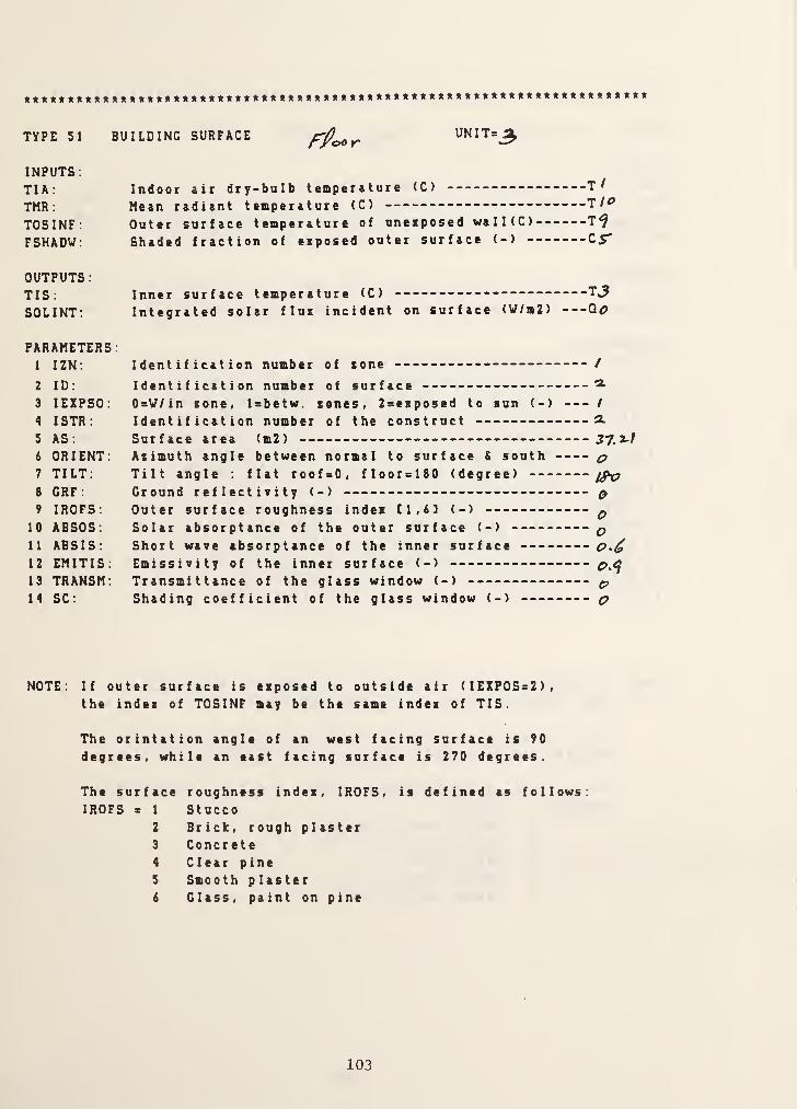
TYPE 51 BUILDING SURFACE UNIT=^rpocr
INPUTS:
TIA: Indoor air dry-bulb temperature <C) T^
TMR ; Mean radiant temperature (C) T/^
TOSINF: Outer surface temperature of unexposed walKC) T^FSHADV: Shaded fraction of exposed outer surface (-) C5"
OUTPUTS
;
TIS: Inner surface temperature (C)
SOLINT: Integrated solar flux incident on surface (V/m2) Qo
PARAMETERS:1 IZN: Identification number of lone /
2 ID: Identification number of surface3 lEXPSO: 0=V/in xone, Isbetw. senes, 2sexposed to sun (-) /
4 ISTR: Identification number of the construct 2.
5 AS: Surface area <m2)
i ORIENT: Asimuth angle between normal to surface & south ^7 TILT: Tilt angle : flat roofsO, floor = 180 (degree)
8 GRF: Ground reflectivity (-) O9 IROFS: Outer surface roughness index [1,83 (-) ^
10 ABSOS: Solar absorptance of the outer surface (-) p11 ABSIS: Short wave absorptance of the inner surface12 EMITIS: Emissivity of the inner surface (-)
13 TRANSM: Transmittance of the glass window (-) g,
14 SC: Shading coefficient of the glass window (-) C?
NOTE: If outer surface is exposed to outside air (IEXPOS=2),the index of TOSINF may be the same index of TIS.
The orintation angle of an west facing surface is 90
degrees, while an east facing surface is 270 degrees.
The surface roughness index, IROFS, is defined as follows:IROFS s 1 Stucco
2 Brick, rough plaster3 Concrete4 Clear pine5 Smooth plaster8 Glass, paint on pine
103
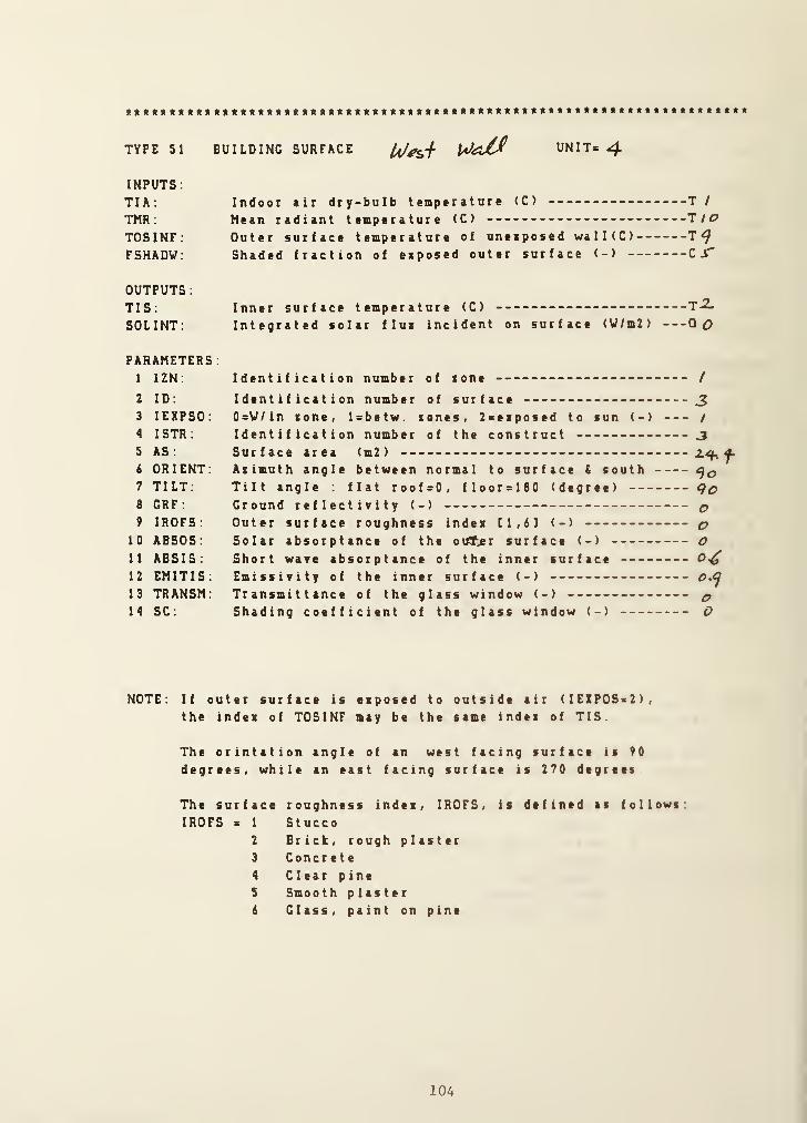
TYPE 51 BUILDING SURFACE UNIT= ^INPUTS:
TIA; Indoor air dry-bulb temperature <C) T /
TMR ; Mean radiant temperature <C) T/c?
TOSINF; Outer surface temperature of uneiposed wa 1 1 ( C ) T<^
FSHADW: Shaded fraction of eaposed outer surface (-) Z S’
OUTPUTS
:
TIS; Inner surface temperature (C) T -2.
SOLINT: Integrated solar flui incident on surface <V/m2) QO
PARAMETERS:1 IZN: Identification number of tone /
2 ID: Identification number of surface 33 lEXPSO: 0=V/in tone, l=betw. tones, 2=eiposed to sun (-) i
4 ISTR; Identification number of the construct 35 AS: Surface area (m2) 2.^^6 ORIENT: Azimuth angle between normal to surface S south7 TILT: Tilt angle : flat roof=0, floor=180 (degree) go8 GRF : Ground reflectivity (-) c>
9 IROFS: Outer surface roughness indet [1,6] (-) c>
10 ABSOS: Solar absorptance of the ouT^r surface (-) O11 ABSIS: Short wave absorptance of the inner surface 0^12 EMITIS: Emissivity of the inner surface (-)
13 TRANSM: Transmittance of the glass window (-) ^14 SC: Shading coefficient of the glass window (-) O
NOTE: If outer surface is esposed to outside air (IE1P0S>2),the indes of TOSINF may be the same indei of TIS.
The orintation angle of an west facing surface is 90
degrees, while an east facing surface is 270 degrees
The surface roughness index, IROFS, is defined as follows.
IROFS s 1 Stucco2 Brick, rough plaster3 Concrete4 Clear pine5 Smooth plaster6 Class, paint on pine
104

TYPE 51 BUILDING SURFACE lO^M UNIT= ^INPUTS;
TIA: Indoor air dry-bulb temperature (C) T^TMR ; Mean radiant temperature (C) T /d?
TOSINF: Outer surface temperature of uneaposed walKC) T^FSHADW: Shaded fraction of esposed outer surface (-)
OUTPUTS
;
TIS ;
SOLINT:Inner surface temperature (C) T
Integrated solar flu* incident on surface (W/m2) Q
PARAMETERS
;
1 IZN. Identification number of xone I
2 ID: Identification number of surface ^3 lEXPSO: 0=V/in sone, l=betw. tones, Z^eiposed to sun (-) j
4 ISTR: Identification number of the construct -3
5 AS; Surface area (m2)
6 ORIENT: Aiimuth angle between normal to surface S south 2.701 TILT; Tilt angle ; flat roof=0, floor=180 (degree)8 GRF ; Ground reflectivity (-) (p
9 IROFS: Outer surface roughness inde* Cl, 83 (-) q10 ABSOS; Solar absorptance of the outer surface (-) (p
11 ABSIS: Short wave absorptance of the inner surface12 EMITIS; Emissivity of the inner surface (-)
13 TRANSM: Transmittance of the glass window (-) q14 SC; Shading coefficient of the glass window (-) p
NOTE; If outer surface is esposed to outside air (IEXPOS=2),the index of TOSINF may be the same index of TIS.
The orintation angle of an west facing surface is 90
degrees, while an east facing surface is 270 degrees.
The surfaceIROFS = 1
2
3
4
5
8
roughness index, IROFS,
StuccoBrick, rough plasterConcreteClear pineSmooth plasterGlass, paint on pine
is defined as follows:
105

TYPE 51 BUILDING SURFACE 10^^ UNIT= 6
INPUTS;
TIA: Indoor air dry-bulb temperature (C) T ^
TMR ; Mean radiant temperature (C) T /c?
TOSINF; Outer surface temperature of uneiposed wa 1 1 ( C ) T^FSHADW: Shaded fraction of eiposed outer surface (-) Cl"
OUTPUTS:TIS; Inner surface temperature (C) T7SOLINT: Integrated solar flux incident on surface (V/m2) Qq
PARAMETERS:1 IZN: Identification number of tone /
2 ID: Identification number of surface3 lEXPSO: 0=V/in tone, Isbetw. tones, 2Btiposed to sun (-) /
4 ISTR: Identification number of the construct 35 AS; Surface area (m2)
6 ORIENT; Aximuth angle between normal to surface S south7 TILT: Tilt angle ; flat roof*0, floorolBO (degree)8 GRF : Ground reflectivity (-)
9 IROFS; Outer surface roughness index [1,6] (-) ^10 ABSOS: Solar absorptance of the outer surface (-) o11 ABSIS; Short wave absorptance of the inner surface12 EMITIS; Emissivity of the inner surface (-)
13 TRANSM: Transmittance of the glass window (-) ^14 SC; Shading coefficient of the glass window (-) ^
NOTE; If outer surface is exposed to outside air (IEZPOSb 2),
the index of TOSINF may be the same index of TIS.
The orintation angle of an west facing surface is 90
degrees, while an east facing surface is 270 degrees
The surface roughness index, IROFS, is defined as follows
IROFS = 1 Stucco2 Brick, rough plaster3 Concrete4 Clear pine5 Smooth plaster6 Glass, paint on pine
106

TYPE 51 BUILDING SURFACE^ ^ UJ^
UNIT= 7
INPUTS.
TIA; Indoor air dry-bulb temperature (C) T/TMR; Mean radiant temperature (C) T /c?
TOSINF: Outer surface temperature of uneaposed walKC) T^FSHADV; Shaded fraction of eiposed outer surface (-) C
OUTPUTS
;
TIS:
SOLINT:
Inner surface temperature (C)
Integrated solar flui incident on surface (V/m2) -Qr
PARAMETERS
;
1 IZN:
2 ID;
3 lEXPSO:
4 ISTR:
5 AS;
6 ORIENT;7 TILT;
8 CRF;
9 IROFS;
10 ABSOS;
11 ABSIS;12 EMITIS;13 TRANSM;14 SC;
Identification number of tone
Identification number of surface0=V/in tone, Isbetw. tones, 2seiposed to sun <-)
Identification number of the constructSurface area (m2)
Atimuth angle between normal to surface S southTilt angle : flat roof=0, floor=180 (degree)Ground reflectivity (-)
Outer surface roughness indes [1,63 (-)
Solar absorptance of the otff^^r surface (-)
Short wave absorptance of the inner surfaceEmissivity of the inner surface (-)
Transmittance of the glass window (-)
Shading coefficient of the glass window (-)
/
4z.
4
e>
2-
0^4^4
oo
NOTE: If outer surface is eiposed to outside air (IEXPOS=2),the indea of TOSINF may be the same indei of TIS.
The orintation angle of an west facing surface is 90
degrees, while an east facing surface is 270 degrees.
The surfaceIROFS = 1
2
3
4
5
6
roughness indea, IROFS,
StuccoBrick, rough plasterConcreteClear pineSmooth plasterClass, paint on pine
is defined as follows;
107
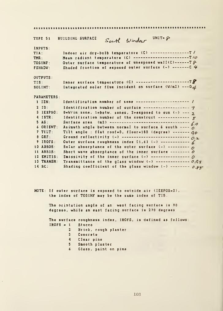
TYPE 51 BUILDING SURFACE
INPUTS:
TIA: Indoor air dry-bulb temperature (C) T /
TMR : Mean radiant temperature (C) T /<?
TOSINF: Outer surface temperature of uneiposed wa 1 1 ( C ) T
FSHADW: Shaded fraction of eiposed outer surface (-) C ^
OUTPUTS:TIS: Inner surface temperature (C) - -
SOLINT: Integrated solar flux incident on surface (V/m2)
PARAMETERS
:
1 IZN: Identification number of tone /
2 ID: Identification number of surface -/
3 lEXPSO: 0=V/in sone, l=betw. sones, Zcexposed to sun (-) 2.
4 ISTR: Identification number of the construct j-
5 AS: Surface area (m2)
6 ORIENT: Asimuth angle between normal to surface S south q7 TILT: Tilt angle : flat roof*0, floorelBO (degree)8 GRF : Ground reflectivity (-)
9 IROFS: Outer surface roughness index 11,6] (-) ^10 ABSOS: Solar absorptance of the outer surface (-) q11 ABSIS: Short wave absorptance of the inner surface O12 EMITIS: Emissivity of the inner surface (-) Q13 TRANSM: Transmittance of the glass window (-)
14 SC: Shading coefficient of the glass window (-)
NOTE: If outer surface is exposed to outside air (IEZPOS>2),the index of TOSINF may be the same index of TIS
The orintation angle of an west facing surface is 90
degrees, while an east facing surface is 270 degrees
The surface roughness index, IROFS, is defined as follows
IROFS = 1 Stucco2 Brick, rough plaster3 Concrete4 Clear pine5 Smooth plaster6 Glass, paint on pine
108

TYPE 53 WEATHER INPUT UNIT= y
INPUTS:
TAMB ; Ambient (outdoor) air temperature (C) T/z.
HUMRAT; Outdoor air humidity ratio (-) HjPBAR: Barometric pressure (kPa) P 3IDN; Direct normal solar radiation (V/m2)
ISKY: Diffuse (sky) solar radiation (W/m2) 07IHOR: Total horiaontal solar radiation (V/m2) Op
OUTPUTS; none
PARAMETERS:1 Indea for ambient temperature (e.g. 5 if TAMB= T5 ) /z.
2 Indei for outdoor air humidity ratio 33 IndeK for barometric pressure 34 Index for direct normal solar radiation ^5 Index for diffuse (sky) solar radiation 76 Index for total horisontal solar radiation p
109

**t«ttft*«*******t**t****t*««**t«***tt*t«***«*t****«**«***«t*«******t«t«
TYPE 52 ZONE MODEL UNIT= io
INPUTS
;
PIAG: Cage pressure of tone air (kPa) P/TIA: Zone air dry-bulb temperature (C) T/VIA; Humidiy ratio of cone air (-) H/PSAC : Cage pressure of supply air (kPa) PxMSA: Mass flow rate of supply air (kg/s) M/TSA ; Supply air dry-bulb temperature <C) T//WSA: Humidity ratio of supply air (-) Ha.QWALL: Convective heat gain from building surfaces (kV) 0
NUMPEP: Number of people (occupant in the tone) C/UTCEQP; Equipment utilisation coeff. (-) CxUTCLIT; Lighting utilisation coeff. (-) Cj
OUTPUTS:TIA: Zone air dry-bulb temperature Idiff. eq.l (C) T/VIA: Humidiy ratio of sone air Cdiff. eq . 1 H/QISV; Internal (short wave) radiant gain from 1 i ght s ( kV) --Q /
QILV; Internal (long wave) radiant gain (kW)
PARAMETER:1 IZN;
2 CFUR:
3 EFFMIA:4 VOLUME;5 SAIREX:6 WPEPS;7 VPEPL:8 VLIT:
9 LIGHT:10 VEQPS;11 VEQPL;12 REQP;
Identification number of sone /
Effective thermal capacitance of furnishing (kJ/K) -
Air mass multiplier for sone moisture capacitanceVo 1 ume of sone air (interior space of sone) (m3)
Std air eichange rate ( 0 . Ss t i gh t , 1 . O-s t d , 1 . 5s 1 eaky )
-
Sensible heat gain from a person (kV)
Latent heat gain from a person (kW)
Heat gain due to lighting in the sone (kV)
1 B Fluorescent, 2 s IncandescentSensible heat gain due to equipment (kW)
Latent heat gain due to equipment (kV)
Radiative to sensible heat from equipment (-)
2.00
/.O
o.o'rtf^
O.
/
o. /S’
0.0 2.
0.2
110

* Initial Conditions of State Variables
PI Zone air pressure, gage 0 . 0 kPa
P2 Supply air pressure, gage 0 . 0 kPa
P3 Barometric pressure of ambient air 101.3 kPa
Ml Supply air mass flow rate 0 . 0 kg /
1
T1 Zone air dry-bulb temperature 20 . 0 C
T2 Inner surface temperature of west wall 20 . 0 C
T3 Inner surface temperature of floor 20 . 0 C
T4 Inner surface temperature of ceiling 20 . 0 C
T5 Inner surface temperature of east wall 20 . 0 C
T6 Inner surface temperature of south wall 20 . 0 C
T7 Inner surface temperature of north wall 20 . 0 C
T8 Inner surface temperature of south window 20 . 0 C
T9 Outer surface temperature of uneaposed surfaces 20 . 0 C
TIO Mean radiant temperature 20 . 0 C
T1
1
Supply air dry-bulb temperature 20 . 0 C
T12 Ambient temperature 20 . 0 C
Cl Number of people 1 . 0
C2 Equipment utilication coefficient 1 . 0
C3 Light utilization coefficient 1 . 0
C4 Shaded fraction of exposed outer surface 0 . 0
C5 Shaded fraction of uneaposed surfaces 1 . 0
Q1 Short wave radiant heat gain 0 . 0 kVQ2 Long wave radiant heat gain 0 . 0 kVQ3 Convective heat gain from building surfaces 0 .
0
kVQ4 Average solar radiation influx of window 0 . 0 kVQ5 Average solar radiation influx of exposed wall 0 . 0 kWQ6 Direct solar radiation 0 . 0 kVQ7 Diffuse solar radiation 0 . 0 kWQ8 Total horizontal solar radiation 0 . 0 kV
HI Zone air humidity ratio 0.0074H2 Supply air humidity ratio 0 . 0074H3 Ambient air humidity ratio 0.0074
111

* Eiecution of HVACGEN
HVACCEN - Simulation GENeration ProgramVersion 1.8 (08-U 1985 )
Choose from the list below;
CReate (SImu la t i on , Block ,UNi t
)
EDit (Simulation, UNit)
View (Simulation, Block. UNit)
HElp
ENd
Selection ?
VI SI ONEZONE
reading from work file....INITIAIIZING TYPES INFORMATION...
Vhat part of the simulation would yon ^ikt to view>
All the simulation information (for documentation)
STructure ( superbl ock , b 1 ock , and unit Information)
VAriable initial values
ERror tolerances, variable scan and freese options
Boundary variables
REported variables
continue with the previous menu
ONE ZONE MODEl
SUPERBIOCK 1
BIOCK 1
UNIT 1 TYPE SO _ ZONE ENVEIOPEUNIT 2 TYPE 51 - BUIIDINC SURFACEUNIT 3 TYPE 51 - BUIIDINC SURFACEUNIT 4 TYPE 51 - BUIIDING SURFACEUNIT 5 TYPE 51 - BUIIDINC SURFACEUNIT & TYPE 51 - BUIIDINC SURFACEUNIT 7 TYPE 51 - BUIIDINC SURFACEUNIT 8 TYPE 51 - BUIIDINC SURFACE
BIOCK 2
UNIT 9 TYPE 53 WEATHER INPUT
112

SUPERBLOCK 2
BLOCK 3
UNIT 10 TYPE 52 - ZONE MODEL
UNIT 1 TYPE 50
ZONE ENVELOPE
1 INPUTS
:
TEMPERATURE 1 - TIA; Zone air dry-bulb temperaturePOWER 1 - QISW: Internal (short wave) radiant gainPOWER 2 - QILW: Internal (long wave) radiant gain
TEMPERATURE 2 - TIS( 1
)
Inner surface temperatureTEMPERATURE 3 - TIS(2) Inner surface temperatureTEMPERATURE 4 - TIS(3) Inner surface temperatureTEMPERATURE 5 - TIS(4> Inner surface temperatureTEMPERATURE 6 - TIS(5) Inner surface temperatureTEMPERATURE 7 - TIS(6) Inner surface temperatureTEMPERATURE 8 - TIS(7) Inner surface temperatureTEMPERATURE 8 - TIS(8) Inner surface temperatureTEMPERATURE 8 - TIS( 9) Inner surface temperatureTEMPERATURE 8 - TIS( 10) : Inner surface temperature
2 OUTPUTS
:
TEMPERATURE 10 - TMR; Mean radiant temperaturePOWER 3 - WALL: Convective heat gain from surfaces
3 PARAMETERS;1 . 00000 IZN: Identification number of sone7 .00000 NS: Number of surfaces of zone
UNIT 2 TYPE SI
BUILDING SURFACE
1 INPUTS:
TEMPERATURE 1 - TIA: Indoor air dry-bulb temperatureTEMPERATURE 10 - TMR; Mean radiant temperatureTEMPERATURE 9 - TOSINF Outer surface temp, of unexposed wallCONTROL 5 - FSHADW Shaded fraction of exposed surface
2 OUTPUTS
;
TEMPERATURE 4 - TIS: Inner surface temperaturePOWER 0 - SOLINT Integrated solar influx on surface
3 PARAMETERS:1 . 00000 IZN: Identification number of zone1.00000 ID: Identification number of surface1 . 00000 lEXPOS: OxV/in sone, Isbetw. xones , 2seiposed to sun1 .00000 ISTR: Identification number of the construct37.2100 AS: Surface area (m2)
0 .000000 ORIENT; Asimuth angle of normal to surface S south0.000000 TILT: Tilt angle; flat roofsO, floor«180 (degree)0 . 000000 CRF; Ground reflectivity (-)
0.000000 IROFS Outer surface roughness index: Instucco,...0 . 000000 ABSOS Solar absorptance of outer surface (-)
0 .600000 ABSIS Short wave absorptance of inner surface(-)0 . 900000 EMITIS; Emissivity of the inner surface (-)
0.000000 TRANSM: Transmittance of the glass window <-)
0 .000000 SC; Shading coeff. of the glass window (-)
113

UNIT 3 TYPE 51
BUILDING SURFACE
INPUTS;
TEMPERATURE 1 -
TEMPERATURE 10 -
TEMPERATURE 9 -
CONTROL 5 -
OUTPUTS;TEMPERATURE 3 -
POWER 0 -
PARAMETERS:1 . 00000 IZN:
2 . 00000 ID:
1 . 00000 lEYPOS2 . 00000 ISTR:
37 .2100 AS:
0 . 000000 ORIENT1 80 . 000 TILT;
0 . 000000 GRF:
0 . 000000 IROFS:
0 .000000 ABSOS;0.600000 ABSIS:0 .900000 EMITIS0.000000 TRANSM0 . 000000 SC;
TIA: Indoor «ir dry-bulb temperatureTMR ; Mean radiant temperatureTOSINF: Outer surface temp, of uneiposcd wallFSHADV; Shaded fraction of eiposed surface
Inner surface temperatureon surface
Identification number of toneIdentification number of surface0=V/in tone, 1 =be tw . t ones , Zxetposed to sunIdentification number of the constructSurface area (m2)
Atimuth angle of normal to surface S southTilt angle: flat roofeO, floorslSO (degree)Ground reflectivity (-)
Outer surface roughness indei : 1 >s t ucco , . . .
Solar absorptance of outer surface (-)
Short wave absorptance of inner surface(-)Emissivity of the inner surface (-)
Transmittance of the glass window (-)
Shading coeff. of the glass window (-)
UNIT 4 TYPEBUILDING SURFACE
51
1 INPUTS;
TEMPERATURE 1 - TIA:TEMPERATURE 10 - TMR;
TEMPERATURE 9 - TOSINFCONTROL 5 - FSHADW
OUTPUTS:TEMPERATURE 2 - TIS;POWER 0 - SOLINT
Indoor air dry-bulb temperatureMean radiant temperatureOuter surface temp of uneiposed wall
Shaded fraction of eiposcd surface
Inner surface temperatureIntegrated solar influi on surface
PARAMETERS:1 . 00000 IZN: Identification number of tons
3 .00000 ID : Identification number of surface1 . 00000 lEXPOS: OsW/in sone, 1 >betw . tones , 2aeiposed to sun
3 . 00000 ISTR: Identification number of the construct24 . 4000 AS; Surface area (m2)
90 .0000 ORIENT: Atimuth angle of normal to surface i sooth90 .0000 TILT: Tilt angle: flat roofsO, flooralSO (degree)
0 . 000000 GRF ; Ground reflectivity (-)
0.000000 IROFS: Outer surface roughness indei 1 as t ucco ,
0 . 000000 ABSOS: Solar absorptance of outer surface (-)
0 . 600000 ABSIS: Short wave absorptance of inner surface(-)0 . 900000 EMITIS: Emissivity of the inner surface ( -
)
0.000000 TRANSM: Transmittance of the glass window (->
0 . 000000 SC ; Shading coeff. of the glass window (-)
114

UNIT 5 TYPE
BUILDING SURFACE51
1 INPUTS:
TEMPERATURETEMPERATURETEMPERATURECONTROL
1 - TIA:
10 - TMR:
9 - TOSINF:5 - FSHADW;
Indoor air dry-bulb temperature
Mean radiant temperatureOuter surface temp, of unenposed wall
Shaded fraction of enposed surface
OUTPUTS
:
TEMPERATUREPOWER
5 - TIS:0 - SOLINT;
Inner surface temperatureIntegrated solar influs on surface
3 PARAMETERS:1 .00000 IZN:
4 .00000 ID:
1 . 00000 lEXPOS3 .00000 ISTR;
24 . 4000 AS;
270.000 ORIENT90 . 0000 TILT:
0 . 000000 GRF:
0.000000 IROFS:
0 .000000 ABSOS;0 .600000 ABSIS:
0 .900000 EMITIS0 .000000 TRANSM0 .000000 SC :
Identification number of zone
Identification number of surface0=W/in zone, l=betw. zones , 2=esposed to sunIdentification number of the constructSurface area (m2)
Azimuth angle of normal to surface & southTilt angle; flat roof^O, floor=180 (degree)Ground reflectivity (-)
Outer surface roughness indes; l=stucco,...Solar absorptance of outer surface (-)
Short vvave absorptance of inner surface(-)Eaissivity of the inner surface (-)
Transmittance of the glass window (-)
Shading coeff. of the glass window (-)
UNIT 6 TYPE 51
BUILDING SURFACE
1
2
INPUTS:
TEMPERATURETEMPERATURETEMPERATURECONTROL
1 - TIA:
10 - TMR:
9 - TOSINF:5 - FSHADW;
Indoor air dry-bulb temperatureMean radiant temperatureOuter surface temp, of unesposed wallShaded fraction of exposed surface
OUTPUTS:TEMPERATUREPOWER
7 - TIS;0 - SOLINT:
Inner surface temperatureIntegrated solar influx on surface
3 PARAMETERS:1 . 00000 IZN:
5 .00000 ID;
1 . 00000 lEXPOS3 .00000 ISTR:
24 . 4000 AS;
leo . 000 OR I ENT90 . 0000 TILT:
0.000000 GRF;
0 . 000000 IROFS:
0 . 000000 ABSOS;0.600000 ABSIS;0 .900000 EMITIS0 . 000000 TRANSM0 . 000000 SC :
Identification number of zoneIdentification number of surface0=V/in zone, Isbetw. zones , 2seiposed to sunIdentification number of the constructSurface area (m2)
Azimuth angle of normal to surface S southTilt angle: flat roofsO, floorclBO (degree)Ground reflectivity (-)
Outer surface roughness indci: lastucco,...Solar absorptance of outer surface (-)
Short wave absorptance of inner surface(-)Emissivity of the inner surface (-)
Transmittance of the glass window (-)
Shading coeff. of the glass window (-)
115

UNIT 7 TYPE 51
BUILDING SURFACE
1
2
INPUTS
;
TEMPERATURETEMPERATURETEMPERATURECONTROL
1 - TIA;
10 - TMR;
6 - TOSINF;4 - FSHADW;
Indoor air dry-bulb temperatureMean radiant temperatureOuter surface temp, of uneiposed wall
Shaded fraction of ezposed surface
OUTPUTS
;
TEMPERATUREPOWER
6 - TIS;
5 - SOLINT;Inner surface temperatureIntegrated solar influi on surface
3 PARAMETERS;1 . 00000 IZN;
6 .00000 ID;
2 . 00000 lEYPOS4 .00000 ISTR;
18 . 4000 AS;
0 .000000 ORIENT90 .0000 TILT;
0 .200000 GRF;
2 . 00000 IROFS;
0 . 600000 ABSOS
;
0.600000 ABSIS;0 . 900000 EMITIS0.000000 TRANSM0 . 000000 SC;
Identification number of toneIdentification number of surfaceOsV/in tone, Isbetw. tones , Zseiposed to sun
Identification number of the constructSurface area (m2)
Azimuth angle of normal to surface S soothTilt angle; flat roof=0, floorslSO (degree)Ground reflectivity (-)
Outer surface roughness indei: l«stucco,...Solar absorptance of outer surface (-)
Short wave absorptance of inner surface(-)Emissivity of the inner surface (-)
Transmittance of the glass window (-)
Shading coeff. of the glass window (-)
UNIT 8 TYPE 51
BUILDING SURFACE
1
2
INPUTS;
TEMPERATURETEMPERATURETEMPERATURECONTROL
1 - TIA;
10 - TMR:8 - TOSINF;4 - FSHADW;
Indoor air dry-bulb temperatureMean radiant temperatureOuter surface temp, of unezposed wall
Shaded fraction of ezposed surface
OUTPUTS;TEMPERATUREPOWER
8 - TIS.
4 - SOLINT;
Inner surface temperatureIntegrated solar influi on surface
3 PARAMETERS;1 . 00000 IZN;
7 . 00000 ID;
2 . 00000 lEZPOS5 .00000 ISTR;
6 . 00000 AS;
0 . 000000 ORIENT90 .0000 TILT;
0 . 200000 GRF ;
6 . 00000 IROFS;0 . 000000 ABSOS;0.000000 ABSIS;0 .000000 EMITIS0 . 950000 TRANSM0 . 850000 SC ;
Identification number of zone
Identification number of surfaceOaV/in zone, 1 abetw. zones , 2aeiposed to sun
Identification number of the constructSurface area (m2)
Azimuth angle of normal to surface t sooth
Tilt angle; flat roofaO, flooral80 (degree)
Ground reflectivity (-)
Outer surface roughness indes lastucco,
Solar absorptance of outer surface (-)
Short wave absorptance of inner surface(-)Emissivity of the inner surface (-)
Transmittance of the glass window (-)
Shading coeff. of the glass window (•)
116
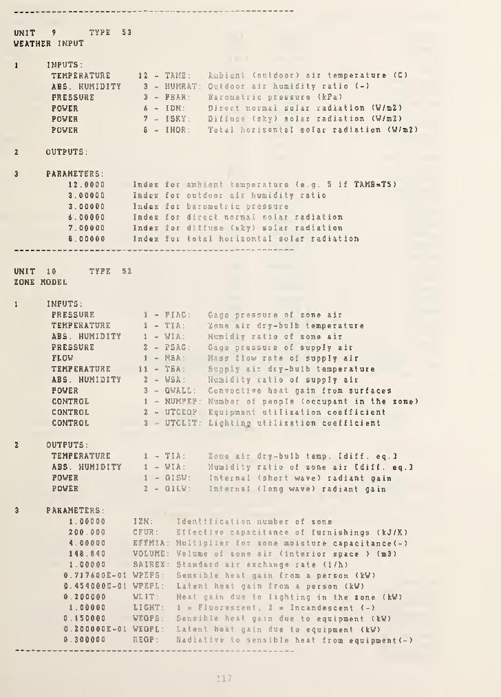
UNIT 9 TYPE 53
WEATHER INPUT
1 INPUTS:
TEMPERATURE 12 - TAMB:
ABS. HUMIDITY 3 - HUMRATPRESSURE 3 - PBAR:
POWER 6 - IDN:
POWER 7 - ISKY:
POWER 8 - IHOR:
Ambisnt (outdoor) air temperature (C)
Outdoor air humidity ratio (-)
Barometric pressure (kPa)
Direct normal solar radiation (V/m2)
Diffuse (sky) solar radiation (V/m2)
Total horisontal solar radiation (V/m2)
OUTPUTS:
PARAMETERS:12 . 0000
3 .00000
3 . 00000i .00000
7 . 00000
8 .00000
Indez
Indes
IndexIndex
IndexIndes
UNIT 10 TYPE 52
ZONE MODEL
1 INPUTS:
PRESSURE 1 -
TEMPERATURE 1 -
ABS. HUMIDITY 1 »
PRESSURE 2 -
FLOW 1 -
TEMPERATURE U -
ABS. HUMIDITY 2 -
POWER 3 -
CONTROL 1 -
CONTROL 2 -
CONTROL 3 -
2 OUTPUTS
:
TEMPERATURE 1 -
ABS. HUMIDITY 1 -
POWER 1 -
POWER 2 -
3 PARAMETERS:1 . 00000 IZN:
200 .000 CFUR:
4.00000 EFFMIA1 46 . 840 VOLUME1 . 00000 SAIREX
0 . 717800E-01 VPEPS:0. 454000E-01 WPEPL:0 . 200000 WLIT:
1 . 00000 LIGHT:0 . 1 50000 VEQPS:0 . 200000E-01 VEQPL
:
0 . 300000 REQP:
5 if TAMB=T5)
PIAG: Gage pressure of gone air
TIA; Zone air dry-bulb temperatureVIA: Humidiy ratio of gone air
PSAG: Gage pressure of supply air
MSA: Mass flow rate of supply air
TSA : Supply air dry-bulb temperatureVSA : Humidity ratio of supply air
QVALL: Convective heat gain from surfacesNUMPEF: Number of people (occupant in the zone)
UTCEQP: Equipment utilization coefficientUTCLIT: Lightis\ji utilization coefficient
TIA: Zone air dry-bulb temp. Cdiff. eq.lVIA: Humidity ratio of zone air Cdiff. eq.l
QISV: Internal (short wave) radiant gainQILW: Internal (long wave) radiant gain
Identification number of zoneEffective capacitance of furnishings (kJ/K)Multiplier for zone moisture capac i t ance ( -
)
Volume of zone air (interior space ) (m3)
Standard air cichange rate (1/h)
Sensible heat gain from a person (kV)
Latent heat gain from a person (kV)
Heat gain due to lighting in the zone (kV)
1 B Fluorescent, 2 « Incandescent (-)
Sensible heat gain due to equipment (kV)
Latent heat gain due to equipment (kV)Radiative to sensible heat from equipment(-)
117
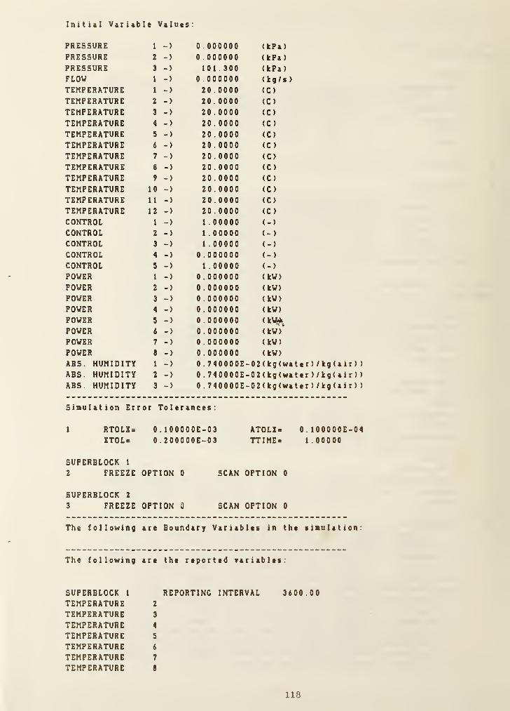
Initial Variable Values;
PRESSURE 1 -> 0 . 000000 (kPa)
PRESSURE 2 -> 0 .000000 (kPa )
PRESSURE 3 -> 101 . 300 (kPa)FLOW 1 -> 0 . 000000 (kg/s
)
TEMPERATURE 1 -> 20 . 0000 (C)
TEMPERATURE 2 -> 20 . 0000 (C)
TEMPERATURE 3 -> 20 . 0000 (C)
TEMPERATURE 4 -> 20 . 0000 (C)
TEMPERATURE 5 -> 20 . 0000 (C)
TEMPERATURE 6 -> 20 . 0000 (C )
TEMPERATURE 7 -> 20 .0000 (C)
TEMPERATURE 8 -> 20 . 0000 (C )
TEMPERATURE 9 -> 20 . 0000 (C)
TEMPERATURE 10 -> 20 . 0000 (C)
TEMPERATURE 1
1
-> 20 . 0000 (C)
TEMPERATURE 12 -> 20 .0000 (C)
CONTROL 1 -> 1 . 00000 (-)
CONTROL 2 -> 1 .00000 (-)
CONTROL 3 -> 1 . 00000 (-)
CONTROL 4 -> 0 .000000 (- )
CONTROL 5 -> 1 . 00000 (-)
POWER 1 -> 0 .000000 (kW)
POWER 2 -> 0 . 000000 (kW)
POWER 3 -> 0 .000000 (kW)
POWER 4 -> 0 . 000000 (kW)
POWER S -> 0.000000 (kVMPOWER 6 -> 0 . 000000 ( kW )*
POWER 7 -> 0 .000000 (kW)
POWER e -> 0.000000 (kW)
ABS. HUMIDITY 1 -> 0 . 740000E- 02 ( kg (water
)
/ kg ( a i r ) )
ABS. HUMIDITY 2 -> 0 . 740000E- 02(kg(water
)
/ kg ( a i
r
)
)
ABS. HUMIDITY 3 -> 0 . 740000E- 02 ( kg (wa t er
)
/ kg ( a i r ) )
Simulation Error Tolerances:
1 RTOLX= O.lOOOOOE-03 AT0LZ> O.lOOOOOE-04ZTOLic 0.200000E-03 TTIME- 1.00000
SUFERBLOCK 1
2 FREEZE OPTION 0 SCAN OPTION 0
SUPERBLOCK 2
3 FREEZE OPTION 3 SCAN OPTION 0
The following are Boundary Variables in the simulation:
The following are the reported variables:
SUPERBLOCK 1
TEMPERATURETEMPERATURETEMPERATURETEMPERATURETEMPERATURETEMPERATURETEMPERATURE
REPORTING INTERVAL 3600.002
3
4
5
6
7
8
118

TEMPERATURE 10
TEMPERATURE 12
POWER 3
POWER 6
POWER 7
POWER 8
SUPERBLOCK 2 REPORTING INTERVAL 3600.00
TEMPERATURE I
ABS. HUMIDITY 1
Selection ?
ENDSTOP
* File: ONEZONE.SIM (Simulation Work File)
ONE ZONE MODEL2
O.lOOOOOE-03 O.lOOOOOE-04 0.200000E-03 0 . 1 OOOOOE-t-0 1
2
3 4 5 6 7 8 8
1 50112 2
10 3
0 . lOOOOOE-^01
2 51
1 10 9 5
4 0
0 . 100000E4-01
0 OOOOOOE+000. 600000E-t-00
3 51
1 10 9 5
3 0
0 . lOOOOOE+010 . OOOOOOE-^00
0 . 600000E+004 51
1 10 9 5
2 0
0 . 100000E4-01
0.900000E-I-02
0 . 600000E-«-00
5 51
1 10 9 5
5 0
0 . lOOOOOE-^01
0 . 270000Ei^03
0 . 600000E-fOO
6 51
1 10 9 5
7 0
0 . lOOOOOE-i-01
0 . 180000E+030 . 600000E4-007 51
1 10 6 4
0 . 700000E-^01
0 . lOOOOOE+010 . OOOOOOE-i-00
0. 900000E+00
0 . 200000E+010 . 1 80000E4-03
0 . 900000Et-00
0 . 300000E-^01
0 . 900000E4-02
0 . 900000E-I-00
0 . 400000E^010 . 900000E4^02
0.900000E400
0 . 500000E4-01
0 . 900000E4020 . 900000E4'00
0. lOOOOOE-^01
0 . OOOOOOE-t-00
0 . OOOOOOEi-OO
0 . lOOOOOE + 01
0 . OOOOOOE-fOO
O.OOOOOOE^OO
0 . lOOOOOE-t-01
0 . OOOOOOE-fOO
O.OOOOOOE+00
0. lOOOOOE^Ol0 . OOOOOOE-fOO
O.OOOOOOE^OO
0 . lOOOOOE^^Ol
0 . OOOOOOE-^00
0 . OOOOOOEt-OO
8 8
0 . lOOOOOE-i-01
0 . OOOOOOE-fOO
0 . OOOOOOE-t-00
0 . 200000E^010 . OOOOOOE-t-00
0 . OOOOOOE-t-00
0 . 300000E+010 . OOOOOOE-fOO
0 . OOOOOOE+00
0 . 300000E1-01
0 . OOOOOOE^OO0 . OOOOOOEi-OO
0 . 300000E4-01
0 . OOOOOOE^OO0 . OOOOOOE^OO
0 . 372100E+020 . OOOOOOE-fOO
0. 372 1 00E>020 . OOOOOOEfOO
0 . 244000E-»-02
0 . OOOOOOE^OO
0 . 244000E^020 . OOOOOOE^OO
0 . 244000E^020 . OOOOOOE+00
119
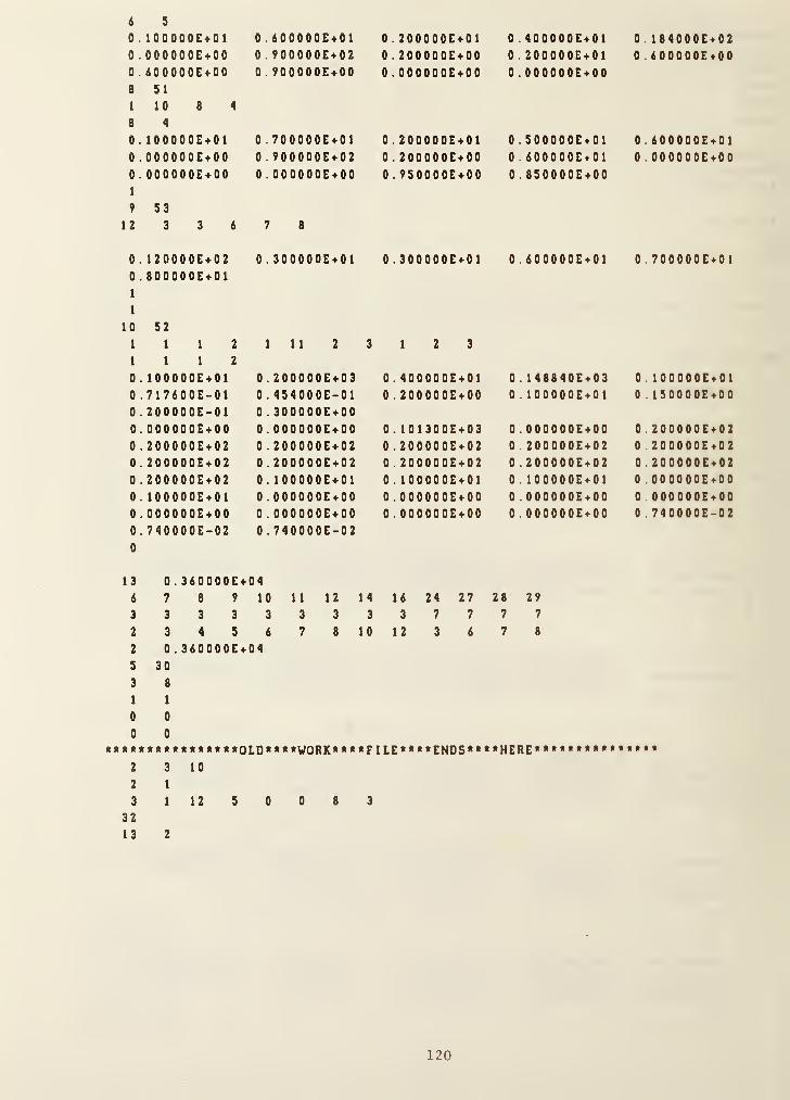
i s
0 . lOOOOOE-t-01
0 . OOOOOOE^OO0 . 600000E-»-00
8 SI
1 10 8 4
8 4
0 . lOOOODE+010 . OOOOOOE-^00
0 . OOOOOOE-^DO
1
9 S3
12 3 3 6
0 . 120000E-i-02
0 . 800000E-t-01
1
1
10 52111211120 . lOOOOOE-i-01
0 . 717600E-010 . 200000E-010. OOOOOOE+000 . 200000E-^02
0. 200000E1-02
0 . 200000E4020 . lOOOOOE^Ol0 . OOOOOOE^OO0 . 740000E-020
0 . 600000E4.01
0 . 900000E4020 . 900000E-I-00
0 . 700000E + 01
0 . 900000E-^02
0 . OOOOOOE^OO
7 8
0 . 300000E-^01
111 2
0 . 200000E1-03
0 . 4S4000E-010 . 300000E^00O.OOOOOOE-fOO
0 . 200000E^020.200000E4^02
0 . lOOOOOE-fOl
0 . OOOOOOE + 00
0 . OOOOOOE-^00
0.740000E-02
0 . 200000E4-01
0 . 200000E-t-00
0 . OOOOOOE-^00
0 . 200000E> 01
0 . 200000E4-00
0 . 9SOOOOE4-00
0 . 300000E-»-01
3 12 3
0. 400000E^010 . 200000E-^00
0 . 1 01 300E>030 . 200000E^020 . 200000E-^02
0 . lOOOOOE-^01
O.OOOOOOE^OO0 . OOOOOOEi-OO
0 .400000E>010 . 200000E^010 . OOOOOOEtOO
0 . SOOOOOE^Ol0 . 60000 0E^01
0 . 8S0000E4.00
0 . 600000E401
0 . 148840E^030 . lOOOOOE^Ol
0 . OOOOOOE^OO0 . 200000E^020 . 200000E>020 . 100000E4010 . 000000E4000 . OOOOOOE^OO
13
6
3
2
2
S
3
1
0
0
0 . 360000E4047 8 9 10
3 3 3 3
3 4 5 6
0 . 360000E^0430
8
1
0
0
11 12 14
3 3 3
7 8 10
16 24 27 28 29
3 7 7 7 7
12 3 6 7 8
«****«« «««*OLDO***VORK**** FILE ****ENDS****HERE2 3 10
2 1
3 1 12 5 0 0 8 3
32
13 2
0 . 184000E>020 . 6 000 00E400
0 . 600000E^010 . OOOOOOE^OO
0 . 700000E^01
0 . lOOOOOE^Ol0 ISOOOOE^OO
0 . 200000E«020 . 2 000 00E«020 . 200000Et020 . OOOOOOE + OO
0 OOOOOOE^OO0 . 74 0000E-02
120

(2) Creation of Model Definition File
* Ciecution of SLIMCON
SiBulation Work File to Model Definition File ConverterVersion 2.1 (November 13, 1984)
Enter the simulation filename (Up to 8 characters) or carriage return to end.
ONEZONE2 superblocks in the simulation MAXIMUM = 10 ( 20 . 0^)
3 blocks in the simulation MAXIMUM = 50 ( 6 . 0%)
2 differential equations in the simulation MAXIMUM = 50 ( 4 . 0%)
399 saved variables in the simulation MAXIMUM = 6000 ( 6 . 74k)
10 units in the simulation MAXIMUM B 200 ( 5 . 0%)
8 units in a single block MAXIMUM = 20 ( 40 . 04k)
2 differential equations in one unit MAXIMUM = 10 ( 20 . 04k)
13 inputs or outputs in a single unit MAXIMUM = 20 ( 65 . 04k)
14 parameters in a single unit MAXIMUM = 30 ( 46 . 74k)
2 blocks in the largest superblock MAXIMUM = 10 ( 20 . 04k)
2 differential equations in one superblock MAXIMUM 20 ( 10 . 04k)
32 state variables in the simulation MAXIMUM = 600 ( 5 . 34k)
14 inputs or outputs in a single block .... MAXIMUM X 50 ( 28 . 04k)
118 unit parameters in the simulation MAXIMUM = 1000 ( 11 . 84k)
8 simultaneous equations in a single block MAXIMUM = 30 ( 26 . 74k)
0 simultaneous equations in one superblock MAXIMUM = 20 ( 0 . 04k)
0 time dependent boundary variables MAXIMUM = 30 ( 0 . 04k)
0 boundary conditions in one superblock . . MAXIMUM = 20 ( 0 . 04k)
13 reported variables in one superblock ... MAXIMUM = 30 ( 43 . 34k)
Model Definition File Complete
• File: ONEZONE.DAT <»«> MODELDEF.DAT (Model Definition File)
ONE ZONE MODEL32 2
2 1
0 . OOOOOOE+000 . 200000E-I-02
0 . 200000E-«-02
0 . 200000E4-020 . 100D00E4^01
0 . OOOOOOE-^00
0 . 740000E-020 3 4 16
8 1 1
0 0
8 0 2
1 2
3
1 2 3 4
9
10
50 51 51 51
13 4 4 4
5 22 23 6
5 14 13 21
0 . OOOOOOE+000 . 200000E>020 . 200000E+020 . lOOOOOE^Ol0 . OOOOOOE-i-00
0 . OOOOOOE-t-00
0 . 740000E-02-1 -1 21 29
5 6 7 8
51 51 51 51
4 4 4 4
7 8 9 10
0. 101300E4030 . 200000E4-02
0.200000E-i-0,2
0 . lOOOOOE^d'i!
O.OOOOOOE^od0 . OOOOOOE-i-00
53 52
6 1 1
11 12 12
0 .OOOOOOE + 00
0 . 200000E4-02
0 . 200000E^020 . lOOOOOE-t-01
0 . OOOOOOE-fOO
0 . OOOOOOE-^00
12 12
0 . 200000E^020 . 200000E4020 . 200000E^020 . OOOOOOE^OO0 . OOOOOOE-^00
0 . 740000E-02
121

5 14 13 21
5 14 13 2 1
5 14 13 21
5 14 13 21
S 14 10 20
5 14 12 20
16 32 3 27
1 5 30 2
2 2 2 2
14 24
8 0
7 0
6 0
9 0
11 0
10 26
12 25
5 30 22 23
0
0
8 7 6 9
0
S 30
0 0 0 0
28
4
29
15
2
31
2
24
2
17
0
18
4
1 9
11 10 12 14
2
30
1 1 58 115 172 229 286 343 400 400
1 3 17 31 45 59 73 87 101 107
.8 399
0. lOOOOOE-t-01 0. 700000E-401 0 . IOOOOOE 4 OI 0 . IOOOOOE 4-OI
0 . 100000E401 0 . 372100E4-02 0 . OOOOOOE 4 OO 0 . OOOOOOE 4 OO
0 . OOOOOOE+00 0 . OOOOOOE-t-00 0 . 6 OOOOOE 4 OO 0 . 9 OOOOOE 4 OO
0 . OOOOOOE4-00 0 . 100000E401 0
.
2 OOOOOE 4 OI 0 . IOOOOOE 4 OI
0 . 372100E402 0.000000E400 0 . I 8 OOOOE 4 O 3 0 . OOOOOOE 4 OO
0 . OOOOOOEi-OO 0
.
6 OOOOOE 4 OO 0 . 9 OOOOOE 4 OO 0 . OOOOOOE 4 OO
0 . IOOOOOE-401 0. 3 OOOOOE 4 OI 0 . IOOOOOE 4 OI 0 . 3 OOOOOE 4 OI
0 . 900000E402 0 . 900000E4-02 0 . OOOOOOE 4 OO 0 . OOOOOOE 4 OO
0 . 600000E4-00 0
.
9 OOOOOE 4 OO O.OOOOOOE 4 OO 0 . OOOOOOE 4 OO
0 . 400000E401 0 . IOOOOOE 4-OI 0 . 300000E401 0 . 244000E4020 . 900000E4-02 0 . OOOOOOE-t-00 O.OOOOOOE 4 OO 0 . OOOOOOE 4 OO
0 . 900000E4^00 0 . OOOOOOE 4 OO 0 . OOOOOOE 4 OO 0 . IOOOOOE 4 OI
0 . lOOOOOE-t-Ol 0 . 300000E4-01 0 . 244000E402 0 . 180000E4030 . OOOOOOE-400 0 . OOOOOOE 4 OO 0 . OOOOOOE 4 OO 0
.
6 OOOOOE 4 OO
0 . OOOOOOE-t-OO 0 . OOOOOOE 4-OO 0 . IOOOOOE 4 OI 0
.
6 OOOOOE 4 OI
0 . 400000E401 0 . 184000E4-02 0 . OOOOOOE 4 OO 0 900000E4020 . 200000E4-01 0 . 6 OOOOOE 4 OO 0 . 600000Et00 0 9 OOOOOE 4 OO
0 . 000000E4-00 0 . IOOOOOE 4-OI 0 . 7 OOOOOE 4 OI 0 2 OOOOOE 4 OI
0 . 600000E-401 0 . OOOOOOE 4-OO 0
.
900000 E 402 0 . 2 OOOOOE 4 OO
0 . 000000E400 0 . OOOOOOE 4 OO 0 . OOOOOOE 4 OO 0 9S0000E4000 . 120000E-402 0
.
3 OOOOOE 4 OI O. 3 OOOOOE 4 OI 0 . 6 OOOOOE 4 O 1
0 . lOOOOOE^Ol0 OOOOOOE^OO0 OOOOOOE^OO0 2 000 00E40 1
0 000000E4000 0OOOO0E4OO0 244000E4020 OOOOO0E4OO0 . 1 OOOOOE40 1
0 270000E4030 400000E4000 SOOOOOE40 1
0 . 900000E4020 900000E4000 200000E4010 200000E4000 000000E«000 300000E4010 iOOOOOE^OI0 8S0000E*000 700000E*01
122
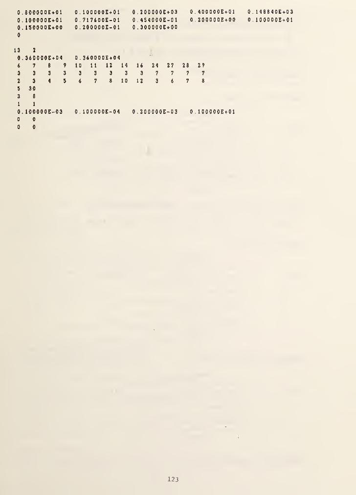
0 . 800000E<»-01 0 . lOOOOOE-i-Oi 0 . 200000E + 03 0 . 40 000 0E-t-01
0 . lOOOOOE-i-01 0 . 717600E-01 0. 454000E-01 0 . 200000E-t-00
0 . ISOOOOE^-OO
0
0 . 200000E-01 0 . 300000E-f00
3 2
0 . 3i0D00E-i-04
6 7 8? 0 . 360000E^0410 11 12 14 16 24 27 28 2?
3 3 3 3 3 3 3 3 3 7 7 7 7
2 3 4 S 6 7 8 1 0 12 3 6 7 8
S 30
3 8
1 1
0. lOOOOOE-03 0 . lOOOOOE-04 0 . 200000E-03 0 . lOOOOOE-i-Ol
0 0
0 0
0 . 14B840E-^03
0 . iOOOOOE-^01
123

( 3 ) Creation of Boundary Variable File
No file for boundary variables is created in this eBanple.
( 4 ) Creation of Conduction Transfer Function File
* Composition of constructs
CONSTRUCT il (Ceiling)
(Outside)
Layer 1 Acoustic tile (47): [material ID. •
in THERM DAT file)2 Ceiling air space (46)
3 Concr e te,4-in. (36)
4 Vinyle tile, 3/32-in. (48)«
(Inside)
* Data for vinyle tile should be added to THERM.DAT file.
Vinyle tile L = 0.002 m, k»0.27 V/mK, > 1 552. 2 kg/m3, Cp«l 00 4 KJ/kg-K
CONSTRUCT #2 (Floor)
(Outside)
Layer 1 Vinyle tile, 3/32-in. ( 48 )
»
2 Concrete, 4-in. ( 36 )
3 Ceiling air space ( 46 )
4 Acoustic tile (47)
(Inside)
CONSTRUCT #3 (Interior Walls)
(Outside)
Layer 1 Piaster, 3/4-in. (43)
2 Air space ( 8 )
3 Plaster, 3/4-in. ( 43 )
(Inside)
CONSTRUCT #4 (Exposed Wall)
124

(Outside)
Layer 1 Face Brick, 4-in. (2)
2 Fiberglass insulation, R-11 (10)
3 Air space (8)
4 Plaster, 3/4-in. (43)
( Inside)
CONSTRUCT #5 (Esposed Glass Window)
(Outside)
Layer 1 Glass, 3/32-in. (49)*
2 Air space (8)
3 Glass, 3/32-in. (49)*
(Inside)
Data for glass: L=k=Cp=0 R=0.26 m2-K/V
* Eaecution of CTFGEN
Enter your choice:
A => Add thermal property data to the constructionmaterials database (THERM.DAT)
B => Print the contents of the data file THERM.DATtoLogicalUnit6
C => Create a CTF data fileD => Change time interval in an enisting CTF data file
E => END
A****ftA*Hr1k*A**AtA*ftAA****t**AAtit**A*A*A*A*A**Aft**A
* A
* YOU ARE NOW ADDING THERMAL PROPERTY DATA *
* INTO THE EXISTING FILE (THERM.DAT) *
* PLEASE ENTER YOUR DATA WITH CARE. *
* METRIC UNITS MUST BE USED. *
* *
************************************************
Enter the name of the construction material(up to 60 characters)
Vi ny 1 e tile
Thickness (meters) =
0 . 002
Conductivity (W/m.C) =
0 .27
Density (kg/m»*3) =
1 552.2Specific heat (kJ/kg.C) =
125
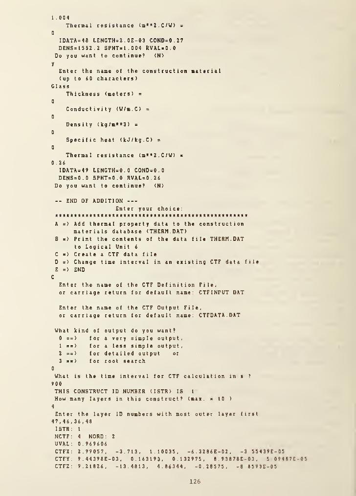
1 . 004
Thermal resistance (m**2.C/V) s
0
IDATA=48 LENGTH=2 . OE-03 COND=0.27DENS=1552.2 SPHT=1.004 RVAL=0 .
0
Do you want to continue? <N>
y
Enter the name of the construction material(up to 60 characters)
GlassThickness (meters) =
0
Conductivity (V/m.C) =
0
Density (kg/m**3) =
0
Specific heat (kJ/kg.C) =
0
Thermal resistance (m**2.C/V) =
0 .26
1DATA=49 LENGTH=0.0 COND=0 .
0
DENS=0.0 SPHT=0.0 RVAL=0.26Do you want to continue? (N>
-- END OF ADDITIONEnter your choice;
*A*ft*it*it**ft**A**it****«)tit***tik*«t***ft**ftik**)trt*****t*
A => Add thermal property data to the constructionmaterials database (THERM.DAT)
B => Print the contents of the data file THERM.DATto Log ical Unit 6
C => Create a CTF data file
D =) Change time interval in an eiisting CTF data file
E => ENDC
Enter the name of the CTF Definition File,
or carriage return for default name; CTFINPUT DAT
Enter the name of the CTF Output File,
or carriage return for default name; CTFDATA DAT
What kind of output do you want ?
0 ==> for a very simple output
,
1 ==> for a less simple output
,
2 ==> for detailed output or
3 ==> for root search0
What is the time interval for CTF calculation in s ?
900
THIS CONSTRUCT ID NUMBER (ISTR) IS 1
How many layers in this construct? (mai. & 10 )
4
Enter the layer ID numbers with most outer layer lint47,46,36,48ISTR; 1
NCTF; 4 NORD
;
2
UVAL; 0.969606CTFX; 2.99057, -3.713, 1.10035, -6.3286E-02, -3 55439E-05CTFY; 9.44398E-03, 0.163193, 0.132975, 8.9387BE-03, 5 09487E-05CTFZ. 9.21826, -13.4813, 4.86344, -028575, -8 8593E-05
126

CTFQ; 0.735784, -6.02473E-02Do you want to continue? <N>
Y
THIS CONSTRUCT ID NUMBER (ISTR) IS 2
How many layers in this construct? (maa. = 10 )
4
Enter the layer ID numbers with most outer layer first
48,36,46, 47
I STR : 2
NCTF: 4 NORD
;
2
UVAL; 0.969606
CTFX: 9.21826, -13.4813, 4.86344, -0.28575, -8.8593E-05CTFY: 9.44398E-03, 0.163193, 0.132975, 8.93878E-03, 5.09487E-05CTFZ; 2.99057, -3.713, 1.10035, -6.3286E-02, -3.55439E-05CTFQ: 0.735784, -6.02473E-02Do you want to continue? <N>
Y
THIS CONSTRUCT ID NUMBER (ISTR) IS 3
How many layers in this construct? (max. = 10 )
3
Enter the layer ID numbers with most outer layer first
43,8,43ISTR 3
NCTF 1 NORD : 1
UVAL 4.71099CTFX 1 1 . 6962 , -6.985 2
CTFY 3.82101, 0.88995CTFZ 11.6962, -6.9852CTFQ 6 . 21576E-06Do you want to continue? <N>
Y
THIS CONSTRUCT ID NUMBER (ISTR) IS 4
How many layers in this construct? (man. = 10 )
4
Enter the layer ID numbers with most outer layer first
2,10,8,43ISTR: 4
NCTF: 3 NORD. 2
UVAL: 0.691656CTFX: 31.2398, -37.7555, 6.8351, -3.14559E-02CTFY. 3.03452E-02, 0.199088, 5.80254E-02, 5.05029E-04CTFZ: 8.55491, -12.8833, 4.6573, -4.09825E-02CTFQ: 0.588904, -5.24332E-03Do you want to continue? (N>
Y
THIS CONSTRUCT ID NUMBER (ISTR) IS 5
How many layers in this construct? (man. = 10 )
3
Enter the layer ID numbers with most outer layer first49,8,49
LAYER L K CP D R RC
Glass 0.000 0 . 000 0 .000 0 .000 0.260 0 .000
Air Space 0 .000 0 .000 0 .000 0.000 0.160 0 .000
Glass 0.000 0.000 0 .000 0.000 0.260 0 000
SUMRC = 0 . 00000 CND = 1 .47059 TINC = 900 , 00
NUMBER OF ROOTS = 7; SEARCH INCREMENT =0.020026
127

N ROOT1 0.0246072S62 0.0723097793 0.1113550034 0.1202925395 0.1364689046 0.1691754027 0.216991657
NUMBER OF RESPONSE FACTORS = 3; ORDER = 2
N 0 0 0 1 0 2 0 3 0 4 0 5
0 3 1 .2398 1 7 3 1 .2398 1 7 3 1 .239817 3 1 .2398 1 7 3 1 .23 98 1 7 31 . 2 39 8 1 7
1 19.358236 -37.473015 - 37 .755497 -37 .7559 42 -37 756010 -37 .756012
2 -4 . 728849 6 . 496254 6 .835099 6 . 835637 6 .835720 6 835722
3 -2.714793 0 .027286 -0 .031456 0 . 000000 0 .000 000 0 000000
0 0 . 030345 0 .030345 0 . 030345 0 . 030345 0 .030345 0 030345
1 0 .216958 0 . 1 9 9 3 62 0 . 199088 0 . 1 990 87 0.199087 0 199087
2 0 . 185634 0 . 059828 0 . 058025 0 . 058023 0 . 05 802 2 0 058022
3 0 . 108688 0 .001 046 0 .000505 0 .000000 0000000 0 000000
0 8 . 554926 8 . 554926 8 .554926 8 .554926 8.554926 8 554926
1 -7 .845255 -12.805930 - 12 .883287 -12.883409 - 1 2 SB 3 4 2 8 -12 883428
2 -0 .007653 4.541511 4 .657307 4 . 657491 4.657519 4 657520
3 -0.004354 0 .000083 -0 .040983 0 .000000 0000000 0 000000
2 0 . 588904 -0 . 005243 0 . 000000 0 . 000000 0000000** SEVERE RESPONSE FACTORS NOT COMPUTED (RESPNS)
ISTR: 5
NCTF: 0 NORD; 0
UVAL; 1.47059CTFX: 1.47059CTFY: 1.47059CTFZ; 1.47059CTFQ;
Do you want to continue? <N>
N
STOP END OF CTF RUN
* File: THERM.DAT ( Thermal Property Data Bank for Building Material!)
1 Stucco/asbestos cement/wood siding plaster, 25 4-mm (1-in )
0.0254 0.692 1858. 0.233 0.036 47.2 A1
2 Facebrick (dense concrete), 101.6-mm (4-in.)
0.1016 1.298 2082. 0.256 0.078 211.4 A2
3 Steel siding (aluminum or other lightweight cladding)0.0015 44.99 7689. 0.116 0.000 11.7 A3
1 2 .7 -mm ( 0 . 5- in . )
0.465 0.011 11
375-in . )
0.465 0.050
4 Slag, membrane,0.0 1 27 1.1 43 88 1 .
5 Felt, 9 .5 -mm (
0
0 .0095 0 .1 90 1 1 21 .
6 Finish0.0127 0.415 1249
.
7 Facebrick, 101.
0.1016 1.332 2002
.
8 Air Space Resistance0.0000 0.000 0 . 0.000 0.160
A4
10.6 A5
0.302 0.031 15.9 A6
6 -mm ( 4 - in . )
0.256 0.076 203.1 A7
B1
120
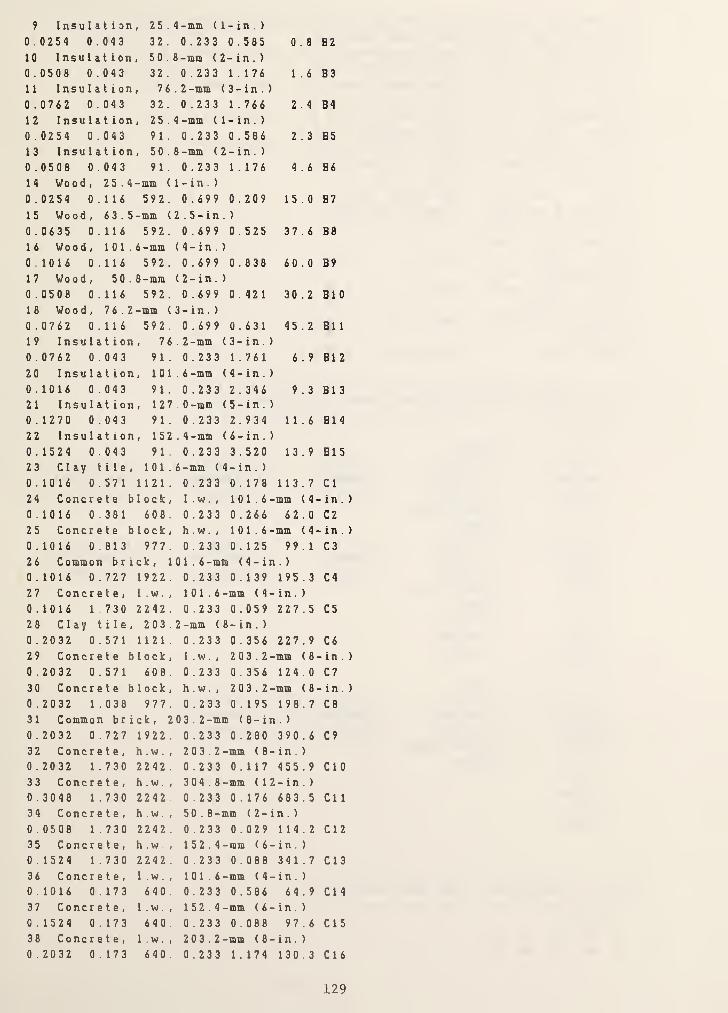
9 Insulation, 25. 4 -mm (
1
- in . )
0 . 0254 0.043 32. 0.233 0 .585 0 . 8 B2
10 Insu 1 at i on , 50 . 8 -mm (2 - in . )
0 . 0508 0.043 32. 0 .233 1.176 1 . 6 B3
11 Insulation, 76 .2 -mm ( 3 - in . )
0 . 0762 0.043 32. 0.233 1 . 766 2 . 4 B4
12 Insulation, 25. 4 -mm ( 1 - in . )
0 . 0254 0.043 91. 0 .233 0.586 2 . 3 B5
13 Insulation, 50. 8 -mm (
2
- in . )
0 . 0508 0.043 91. 0.233 1.176 4 . 6 B6
H Wood, 2 5. 4 -mm (1-in.)
0 . 0254 0.116 592. 0.699 0 .209 15.0 B7
15 Wood, 6 3. 5 -mm (2. 5- in. )
0 . 0635 0.116 592. 0 .699 0 .525 37 . 6 B8
1 6 Wood , 101. 6 -mm ( 4- in . )
0 . 1016 0.116 592
.
0.699 0.838 60 . 0 B9
17 Wood , 50. 8 -mm ( 2-in . )
0 . 0508 0.116 592. 0 .699 0.421 30.2 BIO
18 Wood, 7 6. 2 -mm (3- in.)
0 . 0762 0.116 592. 0.699 0.631 45 . 2 B1 1
19 Insulation, 76 .2 -mm ( 3-in . )
0 . 0762 0.043 91. 0.233 1.761 6 . 9 B12
20 Insulation, 101 .6 -mm ( 4 - in . )
0 . 1016 0.043 91. 0.233 2.346 9 . 3 B1 3
21 Insulation, 127 0-mm ( 5- in .
)
0 . 1270 0.043 91. 0.233 2.934 11.6 B14
22 Insu 1 at i on , 152 .4 -mm ( 6- in . )
0 . 1524 0.043 91. 0 . 233 3.520 13.9 B1523 Clay tile, 101. 6 -mm (4 - in . )
0 . 10 1 6 0.57 1 1 1 2 1 . 0.233 0.178 113.7 Cl
24 Concrete block. 1 .w. , 101.6-mm ( 4-- in .
0 . 1016 0.381 608. 0.233 0 .266 62 . 0 C2
25 Concr e t e block. h.w.. 101.6-mm ( 4-- in .
0 . 1016 0.813 977. 0 .233 0.125 99 . 1 C3
26 Common brick, 101.6-mnt < 4- in . )
0 . 1 0 1 6 0.7 27 1 9 22 . 0.233 0.139 195.3 C4
27 Concrete, l.w.. 101.6-mm ( 4- in . )
0 . 1 0 1 6 1.730 22 42 . 0.233 0 .059 22 7.5 C5
28 Clay tile, 203. 2 -mm (
8
- in . )
0 . 2032 0.571 1121. 0.233 0 . 356 227 . 9 C6
29 Concrete block. I w. , 203.2-mm (8 - in .
0 . 2032 0.571 608. 0 .233 0.356 124.0 C7
30 Concrete block. h.w., 203.2-mm (8 - in .
0 . 2032 1.038 977. 0.233 0.195 198.7 C8
31 Common brick, 2 03. 2 -mm <8- in . )
0 . 20 32 0 .7 27 1 9 22 . 0.233 0 . 280 390 . 6 C9
32 Concrete, h.w.. 203.2-mm ( 8 - in . )
0 . 20 32 1.73 0 22 42 . 0.233 0.117 45 5.9 CIO
33 Concrete, h.w.. 304.8- mm ( 1 2 - in . )
0 . 30 48 1 .730 22 42 . 0 .233 0.176 68 3.5 Cl 1
34 Concrete, h.w., 5 0 .
8 -mm ( 2- in . )
0 . 05 08 1.7 3 0 2 2 42 . 0.233 0.029 114.2 C1235 Concrete, hw., 152.4- mm ( 6- in.)
0 , 1 5 24 1.7 3 0 2 2 42 . 0.233 0 .088 341.7 Cl 3
36 Concrete, l.w.. 101.6- mm ( 4- in.)
0 . 1016 0.173 640
.
0.233 0.586 64.9 Cl 4
37 Concrete, l.w.. 152.4- mm ( 6 - in.)
0 . 1524 0.173 640 0.233 0.088 97 . 6 C1538 Concrete, l.w.. 203.2-mm ( 8 - in . )
0 . 2032 0.173 640. 0.233 1.174 130.3 Cl 6
129

39 Concrete block (filled insulation), I.m., 203.2-mm ( 8- in . )
0 . 2032 0.138 288. 0.233 1 .584 58 . 6 C17
40 Cone r e t e block (filled insulation) , 1 .w. , 2 03 . 2 -mm ( 8- in . )
0 . 2032 0.588 849. 0.233 0 . 348 172.8 C18
41 Concrete block (filled insu 1 at i on
)
, 1 . w . , 304. 8 -mm (12-in. )
0 . 3048 0.138 304. 0.233 2 . 376 92 . 8 C19
42 Concrete block (filled insulation) , 1 . w, 304 .
8 -mm (12-in. )
0 . 3048 0.675 897. 0.233 0 . 456 273 . 4 C20
43 Plaster /gyps urn /similar finishing layer, 19.0 -mm (0 . 75- i n )
0 . 0190 0.7271601. 0.233 0 .026 30 . 5 El
44 Slag or s t one , 12.7 -mm (0.5 - in . )
0 . 0127 1.436 881. 0.465 0 .009 11.2 E2
45 Felt & membrane , 9 .5 -mm ( 0 . 375-in . )
0 . 0095 0.190 1121 0.465 0 . 050 10.7 E3
46 Ceiling air space0 . 0000 0.000 0. 0.000 0 . 176 0 . 0 E4
47 Acoustic tile
0 . 0159 0.061 480. 0.233 0 .315 9 . 2 E5
48 V i ny 1 e tile
0 . 0020 0.270 1552. 1.004 0 . 000 3 . 1 XXX49 Glass0 . 0000 0.000 0. 0.000 0 .260 0 . 0 XXX
* File: CTFDATA.DAT (Conduction Transfer Function File)
900 . 000
1 4 2
2.990570 . 944 39 8E-029.2182607357842 4 2
9.218260 . 9 4 43 98E-022.99057
0 7 357 8 4
3 1 1
11.6962
3.8210111.6962
0 . 62 1576E-054 3 2
31.23980 . 303 45 2E-01
8 .5549 1
0.5889045 0 1
1 .4 7059
1.470591 .4 705 9
0 . 000000
0 . 969606-3 .71300
0.163193-13.4813
-0 . 602473E-010 . 969606
-13.48130.163193-3 .71300
-0 . 602473E-014.71099-6 .9 85 20
0 .88 995 0
-6 .9852 0
0.691656-37 . 75 55
0 . 199088-12.8833
-0 . 524332E-021 . 47059
1 . 10035
0 . 1 3 2975
4.86344
4 .86344
0 . 132975
1 . 1 0035
6.835100 . 58 025 4E-01
4 .65730
-0 . 6 32860E-0 1
0 893878E-02-0 .285750
-0 . 285 75 0
0 . 8 9 387 8E-02-0
. 6 32 8 6 0E-0 1
-0. 3 1 455 9E-01
0 505029E-03-0 409825E-01
-0 355439E-040 509487E-04
-0 885930E-04
-0 885930E-040 509487E-04
-0 355439E-04
* File: CTFINPUT.DAT < CTF Input Data File)
900 .000
4 47 46 36 48
4 48 36 46 47
130

:H4«
PKSi^KrsE-^iasHt Mf im r;»*iff '-v*5^1nr
*V *W^^JW * *V
*9.9%$
.sitvf
4i V tijfi.
|a ^9H!i
J>& ;f9«v^ ^ 8 truf
f ,njA. litt,#nr iii^:i‘o^
ISk, *#•
«
ift' rt >:; ,j%£j.t
H 4, '/iLIS.»? * • » •’,.
'H
.f: ^,1im^s^ kw^/”5^ Ifly ^ -
' :-!:::^»lS!*OT":?^(f'->5 , vs«t>t:fj4''**'5“‘
i •to iiwo«jr8iff»aIiw’ It ,il.t& ^ «livr /baof l/(pr^A]
la^A'.
O'-
/'“*\>'’1
dH^ «; 84 it*!««nfAiw oftiTAina I0 .itjta ?ot»&•fe
.
tTP-IIKTAKV -.*111 •
O«C 0 fi
0900,0OOtO 0
oooovl
es’
-tf
('' i 'i(
lOoH.OOOOO.f
e;ie,ai
0000>l0809 •
OOIO 0
9*00 0
0000 0
oeoo 0
0900 9
O0«0 0
0909 0
to to. Ml IHOvOUMtIO 00*9.
»
tm.tol mo tor, voog.l
fi VUl!fn U't<t,9H 0009 0
tr sioo.ftt toof.ou 0900 0
if nu eti oeoo.ioo^.oooo.*0120 JIt *0f|| ,M 0 0600 >0
If loiroir -oeu .009 000040 9 fO 44 erii. Mlo.j 9j •JiO’^9’-
89 .trQt.9fl tm.Jfl J90I4
f 00 e II
9000., I 90H - tot flit « <
J09J 0 fii 0041 m IJiO t)
leoi ft oftoiroi fjto 0
609ft. iftix u;l« 0
ocit.iOi «iio,«
.T101 19
6001 U99H tl
B99I.0;
9 . D
• I
64omi 6 i'*....:rjt,'9
49*C. tfti.^ Ilift.fi
6601. ifti fttH 0
fiOOflOj JJtO 0
9900. Ml lOM 0
OjJtlfl t*M 1
ifrOft (01 ftSK 0
9900.19^ mi 9
J99I tor MfO 6
OOftllyMl MM I
fiolMOi ^ iiit>.i
d96e4«lj^M9 9
oooo |i0MJ,4i6 H«‘ P10'-' 1 i:MOf tt
9I«0 fj
JJOt it
MOV '5
99i* II
?m ¥1
oftftft.te
0 ft
9 e
1 >
• t
0 4
Q ^
1 ft! T
ft. I r 1
ftit ft
5.f( t
9 M t
C , t| ft
t
r
9
4,..
V4>II
ft'
T
t
«
1
ft
»
ft
t
t
ft
tt
r
f
ft
ft
t
f
ft

(5) Creation of Weather Data File
* Eaecution of CRWDTA
***********1t1i*1ili***t***i(i(tl(**lttlilt*1t1(**'k1rl(*1Hrk***li
* *
* CREATING A WEATHER DATA FILE *
* »
A************************************************
Enter LATITUDE, LONGITUDE, and TIME ZONE;38.85
77 . 03
5
Enter one of the following:1 - to process the weather data in file WTPOUT.DAT
(previously read from weather tape by program RDTAPE)2 - to generate clear sky design data3 - to generate cloudy sky design data
2
Enter output file name (up to 12 characters)or carriage return for default name: WEATHER.DAT
Enter initial day and month, and number of days
for which weather calculations will be made;
7,7,2Enter pressure (kPa), wind speed (m/s), andrelative humidity (from 0.0 to 1.0):
101.3,0,0.8Enter minimum and maximum temperatures;
20,30Enter visibility (km); if value unknown use 0:
0
Enter geographic correction factor
[ASHRAE Fund. 1981, p.27.8]; if value unknown use 1:
1
STOP END OF CREATING WEATHER FILE
* File: WEATHER.DAT
7 7 38 .85 77,. 03
7 7 0 . 0 2 1 .8000 0.0133
7 7 1 . 0 2 1 . 3000 0.0128
7 7 2 . 0 20 .8000 0.0124
7 7 3 . 0 20 . 4000 0.0121
7 7 4 . 0 20 . 1 000 0.0119
7 7 5 . 0 20 . 0000 0.0118
7 7 i . 0 20 .20 00 0.01207 7 7 . 0 20.7000 0.01247 7 8 . 0 21.6000 0.0131
7 7 9 . 0 22.9000 0.01427 7 10.0 24.4000 0.01567 7 11.0 26 . 1000 0.01737 7 12 . 0 27.7000 0.01907 7 13.0 28 .9000 0 . 0205
7 7 14.0 29.7000 0.02157 7 15.0 30 . 0000 0.0218
5.00 2
1 0 1 .30 00 0 . 0000 0 0000 0
1 0 1 .30 00 0.0000 0 .0000 0
101 . 3000 0.0000 0 00 00 0
101 .3000 0.0000 0 .0000 0
101.3000 0 . 0000 0 0000 0
101 .3000 0.0000 0 0 0 00 0
101 . 3000 0.0000 194 7 8 09 26
101 .3000 0 .0000 582 14 11 80
101 . 3000 0 00 00 741 25 8 3 102
101.3000 0 . 0000 8 1 9 7 2 2 2 1 1 3
1 0 1 . 300 0 0 00 00 862 76 4 6 1 1 9
1 0 1 .3000 0 .0000 886 66 5 0 122
101.3000 0.0000 898 1992 123
1 0 1 .30 00 0.0000 900 1 130 124
1 0 1 . 3000 0.0000 892 8 2 98 123
1 0 1 . 3000 0.0000 874 6 8 9 2 120
000 0
0 00 0
0 00 0
0 000
0 00 0
0 000
8 7 98
3 3 5 5
2 9 37
12 17
0(15
3 5 98
95 1 5
2154
2105
7 07 1
132
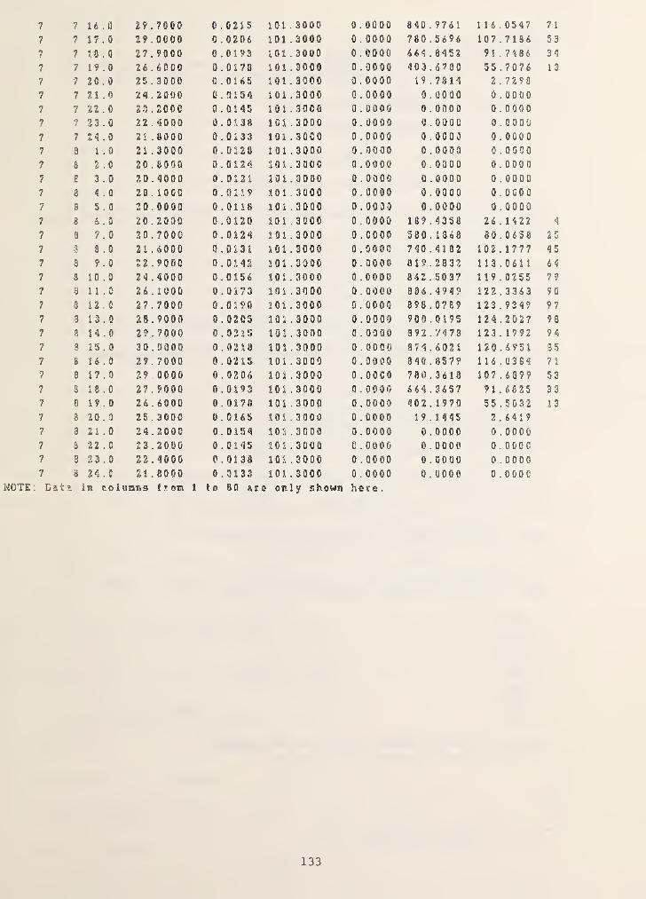
7 7 16.0 29 .7000 0.0215 101 . 3000 0 . 0000 840 . 9761 116. 0547 7 1
7 7 17.0 29 . 0000 0 . 0206 101 .3000 0 . 0000 780 .5696 107.7186 53
7 7 18.0 27 . 9000 0.0193 101.3000 0 . 0000 664 .8452 91.7486 34
7 7 19.0 26 . 6000 0.0178 101 . 3000 0.0000 403 .6780 55 .7076 13
7 7 20 . 0 25 . 3000 0.0165 101 . 3000 0.0000 19.7814 2.7298
? 7 21.0 24 . 2000 0.0154 101 .3000 0 . 0000 0 . 0000 0 .0000
7 7 22 . 0 23 . 2000 0.0145 101.3000 0 . 0000 0 .0000 0.0000
7 7 23 .
0
22 . 4000 0.0138 101 .3000 0 . 0090 0 . 0000 0.0000
7 7 24 . 0 21 . 8000 0.0133 101 . 3000 0 .0000 0 . 0000 0.0000
7 9 1 . 0 21 .3000 0.0128 101 .3000 0 . 0000 0 . 0000 0 .0000
7 8 2 . 0 20 . eooo 0.0124 101 .3000 0.0000 0 . 0000 0.0000
7 8 3 . 0 20.4000 0.0121 101.3000 0 . 0000 0 . 0000 0 .0000
7 8 4 . 0 20 . 1 000 0.0119 1013000 0 .0000 0.0000 0 . DGOO
7 S 5 . 0 20.0000 0.0118 101 .2000 0 . 0030 0 . 0000 0 .0000•It 8 6 . 0 20 . 2000 C . 0120 101.3000 0 . 0000 1 89 . 4358 26 . 1 4 22 4
1 8 7 . 0 20 . 7000 0.0124 1 01 .3000 0 . 0000 580 . 1 368 80 .0658 25
7 3 3 . 0 21.6000 0.0131 101 . 3000 0.0000 740 .4182 1 02 . 1 777 45
7 3 9 .
0
22 . 9000 0.0142 101 .3000 0 . 0000 819.2832 113.0611 6 4
7 S 10.0 24 . 4000 0.0156 101.3000 0 . 0000 862 . 5037 1 1 9 .0255 7 ?
7 3 11 . 0 26 . 1000 0.0173 101 . 3000 0 . 0000 386 . 4949 122.3363 90
7 3 12 . 0 27 . 7000 0.0190 101 . 3000 0 . 0000 898 . 0769 1 23 . 93 49 97
7 8 13.0 28 . 9000 0 . 0205 101 .3000 0 . 0000 900.0195 124.2027 98
7 8 H . 0 29 . 7000 0.0215 101 . 3090 0 . 0900 892.7473 123 . 1992 94
7 3 15.0 30 . 0000 0.0218 101 .3000 0 . 0000 874.6021 120 .6951 35
7 S 16.0 29 . 7000 0 . 0215 101 .3000 0 . 9000 340 . 8579 1 16 . 0384 71
7 8 17 . 0 29 . 0000 0.0206 101 .3000 0 . ooco 780.3618 107.6899 53
7 S 18.0 27 . 9000 0.0193 101.3000 0 . 0900 664.3657 91.6825 33
7 8 19.0 26 . 6000 0.0178 101 . 3000 0 . 0000 402 . 1970 55 . 5032 13
7 3 20 . 3 25 . 3000 0.0165 101 . 3000 0 . 0000 19.1445 2.64197 8 21.0 24 . 2000 0.0154 101 .3000 0 . 0000 0 .0000 0 .0000
7 8 22 . 0 23 . 2000 0.0145 101 . 3000 0 . 0900 0 . 0000 0.00007 @ 23.0 22 . 4000 0.0138 101 . 3000 9 . 0000 0 .0000 0 . 00007 a 24 . 0 21 . 8000 0.0133 101.3000 0 . 0000 0 . 0000 0 . 0000
MOTE : Dat ;5 in colnaris froisi 1. to 80 ar
s
1 only shown here .
133
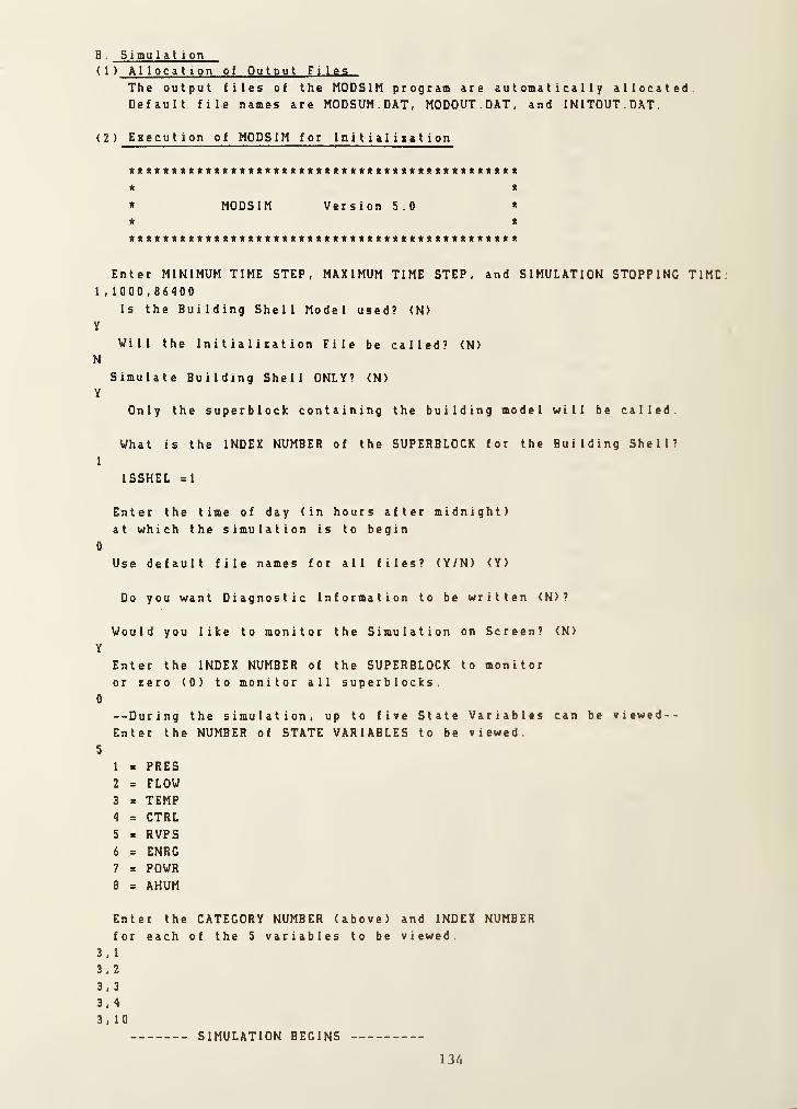
B . Simulation( 1 ) Allocation of Output Files
The output files of the MODSIM program are automatically allocatedDefault file names are MODSUM.DAT, MODOUT.DAT, and INITOUT.OAT
( 2 ) Eaecution of MODSIM for Ini t ial iiat ion
* *
* MODSIM Version 5.0 *
« *
<[****A**ft*A*****A****l(*(rA«*ft*ftA***ft)II***«***llt**
Enter MINIMUM TIME STEP, MAXIMUM TIME STEP, and SIMULATION STOPPING TIME:
1 , 1 000,6 6400
Is the Building Shell Model used? <N>
y
Will the Initialisation File be called? <N>N
Simulate Building Shell ONLY? <N>
Y
Only the superblock containing the building model will be called
What is the INDEX NUMBER of the SUPERBLOCK for the Building Shell?
1
ISSHEL =1
Enter the time of day (in hours after midnight)at which the simulation is to begin
0
Use default file names for all files? (Y/N) <Y>
Do you want Diagnostic Information to be written <N>?
Would you like to monitor the Simulation on Screen? <N>
Y
Enter the INDEX NUMBER of the SUPERBLOCK to monitoror zero (0) to monitor all superblocks.
0
--During the simulation, up to five State Variables can be viewed--
Enter the NUMBER of STATE VARIABLES to be viewed
5
1 = PRES2 = FLOW3 = TEMP4 = CTRL5 = RVPS6 = ENRG7 = POWR8 = AHUM
Enter the CATEGORY NUMBER (above) and INDEX NUMBERfor each of the 5 variables to be viewed
3 , 1
3 , 2
3 , 3
3,4
3,10
SIMULATION BEGINS
13 /.

FIRST WEATHER DATA SKT HAS BEEN READ
20 .0000 20 . 1286 2 0.163 4 20.0601 20.1227
SB 2 : TIME =1.0 NT I ME =2 TST•EP =1.0 PSTEP = 5 . ;) M3 3
20 .0007 20.1206 20.1634 2 0.0 6 0 t 20.1227
SB 1 : TIMS =900 .
0
NTIME =3 TSTEP =399.0 P3TEP=iO00 .
0
20 . 0007 20 . 1753 20 . 3496 20 . 2146 20.3603
SB 1 : TIME =1300 . 0 NTIME =4 TSTEP = 900 . 0 PS7EP=1000 .
0
20 . 0007 20 .2086 2 0.393 ). 20 . 2 35 3 20.4108
SB 1 : TIME =2700 . 0 NTIME =5 TSTEP 900 0 PSTKP=1000 .
0
20 . 0007 20 .2298 20 . 4063 2 0.32 1
"
20.4387
SB 1 ; TIME =3600 . 0 NTIME =6 TSTEP = 900 0 ?STEP=100C .
0
20 .0007 20 . 2432 20.4121 20 . 3429 20.4557SB 1 : TIME =4500 . 0 NTIME =7 TSTEP = 900 . 0 PSTEP=1000 .
0
20 . 0007 20 .2516 20.4156 2 0 .356 <1 20.4666SB 1 ; TIME =5400 . 0 NTIME =3 TSTEP = 900 . 0 PSTE1‘ = 1000 . 0
20 .0007 20 .2570 3 0.417 0 20.3662 20.4736SB 1 : TIME =6300 . 0 Nl’IME =9 TSTEP = 900 .
0
PSTEP=1000 .
0
20 .0007 2 0 . 2 6 ((
4
2 0 . 4 1 *> 3 20.3733 20.4780SB 1 : TIME =7200
.
0 NTIME =10 TSTEP = 900 . 0 PSTEP=1000 .
0
20 . 0007 20.2625 20 . 4201 2 0.3 7 8 4 20.4806SB 1 ; TIME =8100 . 0 NTIME =11 TSTEP = 900 .
0
PSTSP=1000 .
0
20 .0007 2fi .2637 30 .4204 2 0 . 3 8 2 2 20.4619SB 1 ; TIME =9000 . 0 NTIME =12 TSTEP = 900 . 0 PSTEP=1000 .
0
20 . 0007 20 . 2642 20.4202 2 0 ..384 8 20 . 4821
( OUTPUTS FROM TIME=9900 TO 301 00 ARE DELETED )
SB1 1 ; TIME =8 1000 . 0 NTIME =92 TSTEP =900. C PSTEP=1000. 0
20 .0007 20.4094 20 . 6504 20 . 6317 20.7577SB 1 : TIMS =31900 .0 NTIME =93 TSTEP = 900 .
0
PSTL’P = i 0 00 . 0
20 .0007 20 . 3949 20 . 6269 2 0 . 6 0 50 20 .7303
SB 1 ; TIME =82800 .0 NTIME =94 TSTEP = 900 .
0
PSTEP=i000 .0
20.000? 20 . 3620 20 .6061 20.581
9
20 .7060SB 1 : TIME =83700 .0 NTIME =95 TSTEP = 900 . 0 FSTEP=1000 .
0
20.0007 20.3706 20 . .5 3 7'’ 2 0 . 5618 20.6843SB 1 : TIME =84600 .0 NTIME =96 TSTEP = 900 . 0 P!r.’EP = lQ00 . 0
20.0007 20 . 3604 2 0 .57 1
3
2 0.5 4 4 1 20 .6648
SB 1 : TIME =65500 .0 NTIME =97 TSTEP = 900 . 0 PSTEP=1000 .
0
20.0007 20.3512 20 . 55 66 20 . 5285 20 .6472
SB 1 ; TIME =86400 .0 NTIME =98 TSTEP = 900 . 0 PSTEP=1000 .
0
20.0007 20.3429 20 .5433 2 0 . 5147 20.6313
STOPINITiALIZATIOM fl'LE HAS BEEN WRITTEN
end or SIMULATION
* File; MODSUM.DAT (for (he in i t i a i i. Rut i on run)
***** PROGRAM MODS I
M
*«*)<*
a MODuIar SINulation progran
ONE ZONE MODEL
2 SUPERBLOCKS 3 Pil.OCKS 1(1 UNITS
32 STATE VARIABLES:3 PRES 1 FLOW n TEMP I. CTRL 8 POWR 3 AHUM
INITIAL STATE VECTOR:
135
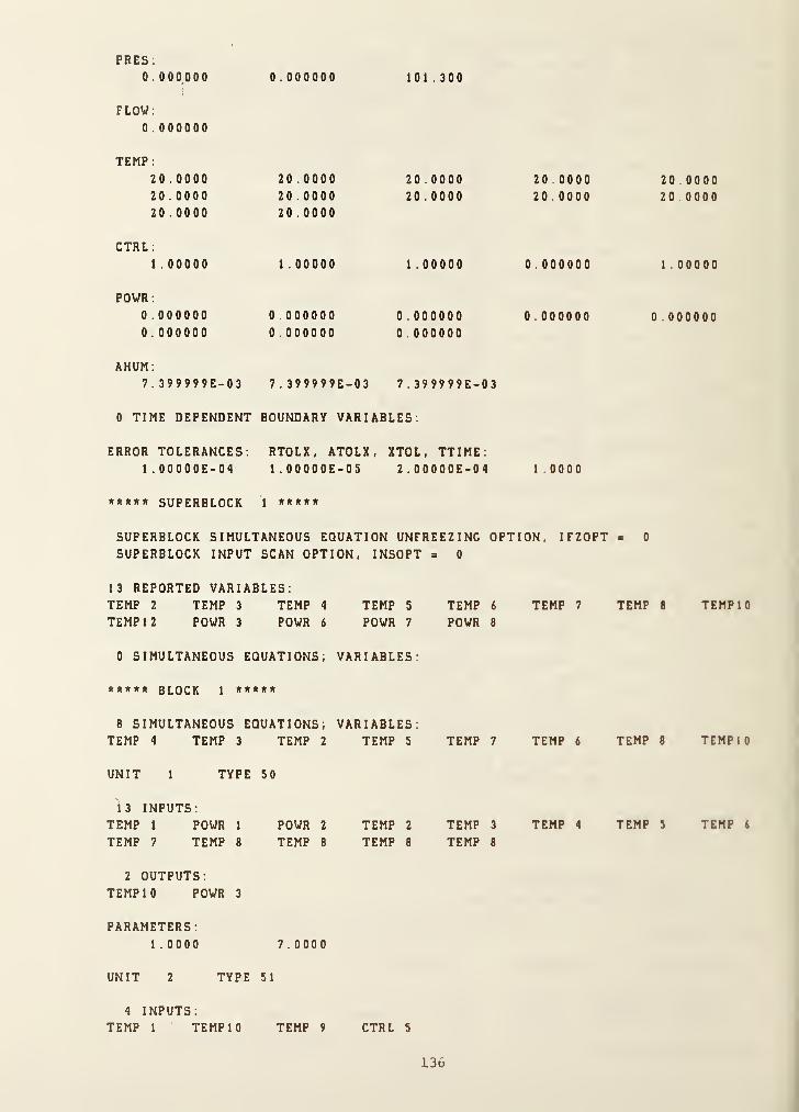
PRES:
0.000000 0.000000 101.300I
'
FLOW;
0 .000000
TEMP ;
20.000020 . 0000
20 . 0000
20.000020 .0000
20 . 0000
20 .0000
20 .0000
20 . 0000
20 .000020 .0000
20 . 0000
CTRL :
1 . 00000 1 . 00000 1 .00000 0 . 000000 1 00000
POWR :
0 . 0000000 . 00 0000
0 .000000
0 .0000000 . 0000000 .000000
0 . 000000 0 .000000
AHUM;
7 . 399999E-03 7 . 399999E-03 7 . 399999E-03
0 TIME DEPENDENT BOUNDARY VARIABLES;
ERROR TOLERANCES.1 . OOOOOE-04
RTOLX, ATOLX,1 . OOOOOE-OS
XTOL, TTIME:2 . OOOOOE-04 1 0000
***** SUPERBLOCK 1 *****
SUPERBLOCK SIMULTANEOUS EQUATION UNFREEZING OPTION, IFZOPT « 0
SUPERBLOCK INPUT SCAN OPTION, INSOPT = 0
13 REPORTED VARIABLES;TEMP 2 TEMP 3 TEMP 4 TEMP 5 TEMP 6 TEMP 7 TEMP 8 TEMP 10
TEMP 12 POWR 3 POWR 6 POWR 7 POWR 8
0 SIMULTANEOUS EQUATIONS; VARIABLES.
***** block 1 *****
8 SIMULTANEOUS EQUATIONS; VARIABLES:TEMP 4 TEMP 3 TEMP 2 TEMP 5 TEMP 7 TEMP 6 TEMP 8 TEMPI 0
UNIT 1 TYPE SO
13 INPUTS;TEMP 1 POWR 1 POWR 2 TEMP 2 TEMP 3 TEMP 4 TEMP 3 TEMP i
TEMP 7 TEMP 8 TEMP 8 TEMP 8 TEMP 8
2 OUTPUTS:TEMP 10 POWR 3
PARAMETERS:1.0000 7 .0000
UNIT 2 TYPE 51
4 INPUTS;TEMP 1 TEMP 10 TEMP 9 CTRL 5
136

2 OUTPUTS:TEMP 4 NULL 0
PARAMETERS
:
1 . 0000
0 .00000
0 .60000
1 . 0000
0 . 000000 . 90000
1 . 0000
0 .08000
0 . 00000
1 .0000
0 . 000000 .00000
37.2100 . 00000
UNIT 3 TYPE 51
4 INPUTS:
TEMP 1 TEMP 10 TEMP 9 CTRL 5
2 OUTPUTS:TEMP 3 NULL 0
PARAMETERS:1 . 0000
0 .000000 . 60000
2 . 0000180.00
0 . 90000
1 . 0000
0 .00000
0 . 00000
2 . 00000 .00000
0 . 00000
37.2100 .00000
UNIT 4 TYPE 51
4 INPUTS:
TEMP 1 TEMP 10 TEMP 9 CTRL 5
2 OUTPUTS:TEMP 2 NULL 0
PARAMETERS:1 . 000090 . 000
0 . 60000
3 . 000090 . 000
0 .90000
1 . 0000
0 .00000
0 . 00000
3 . 0000
0 .00000
0 . 00000
24.4000 . 00000
UNIT 5 TYPE 51•
4 INPUTS:
TEMP 1 TEMP 10 TEMP 9 CTRL 5
2 OUTPUTS:TEMP 5 NULL 0
PARAMETERS
:
1 . 0000
270 .00
0 . 60000
4 . 0000
90 .000
0 . 90000
1 . 0000
0 . 00000
0 . 00000
3 .0000
0 . 00000
0 .00000
24.4000.00000
UNIT 6 TYPE 51
4 INPUTS:
TEMP 1 TEMP 10 TEMP 9 CTRL 5
2 OUTPUTS:TEMP 7 NULL 0
PARAMETERS:1.0000180.00
0 .60000
5 . 000090 .000
0 . 90000
1 . 00000 .00000
0 . 00000
3 . 0000
0 . 00000
0 . 00000
24.4000.00000
137
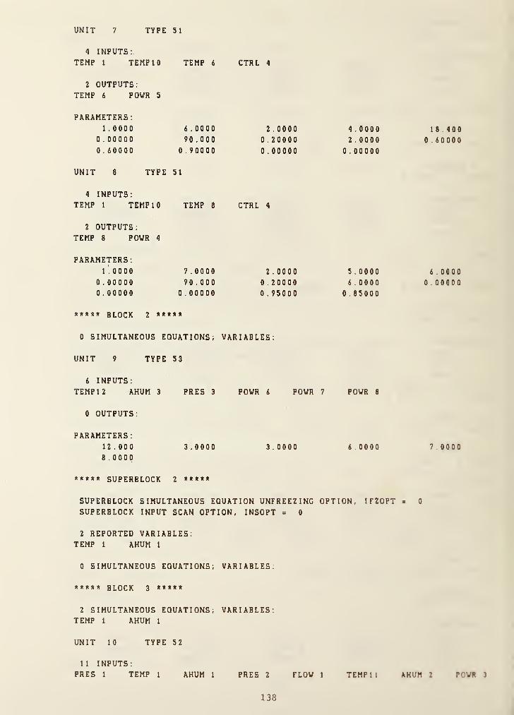
UNIT 7 TYPE 51
4 INPUTS:
TEMP 1 TEMP 10 TEMP 6 CTRL 4
2 OUTPUTS:TEMP 6 POWR 5
PARAMETERS:1 . 0000 6 .0000 2 . 0000 4 .0000
0 . 00000 90 .000 0 .20000 2 .0000
0 . 60000 0 . 90000 0 . 00000 0 . 00000
UNIT 8 TYPE 51
4 INPUTS:TEMP 1 TEMP 10 TEMP 8 CTRL 4
2 OUTPUTS:TEMP 8 POWR 4
PARAMETERS:1 . 0000 7 .0000 2 . 0000 5.0000 6.0000
0.00000 90 .000 0 .20000 6.0000 0.000000 .00000 0 . 00000 0 . 95000 0 . 85000
***** block 2 *****
0 SIMULTANEOUS EQUATIONS; VARIABLES:
UNIT 9 TYPE 53
6 INPUTS:
TEMP 12 AHUM 3 PRES 3 POWR 6 POWR 7 POWR 8
0 OUTPUTS:
PARAMETERS
:
12.000 3.0000 3.0000 6.0000 7 0000
8 .0000
***** SUPERBLOCK 2 *****
SUPERBLOCK SIMULTANEOUS EQUATION UNFREEZING OPTION, IFZOPT « 0
SUPERBLOCK INPUT SCAN OPTION, INSOPT = 0
2 REPORTED VARIABLES:TEMP 1 AHUM 1
0 SIMULTANEOUS EQUATIONS; VARIABLES:
***** block 3 *****
2 SIMULTANEOUS EQUATIONS, VARIABLES:TEMP 1 AHUM 1
UNIT 10 TYPE 52
11 INPUTS:PRES 1 TEMP 1 AHUM 1 PRES 2 FLOW 1 TEMP 11 AHUM 2 POWR 3
138

CTRL 1 CTRL 2 CTRL 3
4 OUTPUTS:
TEMP 1 AHUM 1 POWR 1 POWR 2
PARAMETERS:1 . 0000 200 . 00 4 . 0000 148.84 1.0000
7 . 17600E-02 4 . 54000E-02 0 .20000 1.0000 0.15000
2 . OOOOOE-02 0 .30500
TMIN = i.OOO TMAX = iOOO.OOO TSTOP = 86400. OOQ
BUILDING SHELL MODEL IN SUPERBLOCK 1:
CONSTANT TIME STEP TSHELL = 900.00
WEATHER DATA: LATITUDE = 38.850 LONGITUDE = 77.030STARTING DATE: 7 JUL
.
SOURCE: CLEAR SKY DESIGN DAY METHOD
****#*»«»* SUPERBLOCK 1******«**»
TIME = 3600.00TEMP 2 TEMP 3 TEMP 4 TEMP 5 TEMP 6 TEMP 7 TEMP 8 TEMP 1
C
20 . 2 20 . 4 20 . 3 20 . 2 20 . 4 20 . 2 20.5 20 . 5
TEMP 12 POWR 3 POWR 6 POWR 7 POWR 8
21.3 4 . 71 lE-02 0 . 000 0 .000 0.000
t**tt**t** SUPERBLOCK 1
TIME = 7200 . 00
TEMP 2 TEMP 3 TEMP 4 TEMP 5 TEMP 6 TEMP 7 ^TEMP 3 TEMP 10
20.3 20 . 4 20 . 4 20 . 3 20 . 5 20.3 20 . 5 20 .5
TEMP 12 powrS Foim 6 POWR 7 POWR 8
20 . 8 5 . 145E-02 0.000 0.000 0 . 000
********** SUPERBLOCK 1 ««**«***«*
TIME = 10800.00TEMP 2 TEMP 3 TEMP 4 TEMP 5 TEMP 6 TEMP 7 TEMP 8 TEMP 10
20 . 3 20 . 4 20 . 4 20 . 3 20 . 5 20 . 3 20 . 4 20 . 5
TEMP 12 POWR 3 POWR 6 POWR 7 POWR 8
20.4 5 . 097E-02 0 .000 0 .000 0.000
( OUTPUTS FROM TIME=14400 TO 79200 ARE DELETED)
**«**»**** SUPERBLOCK 1 *»»*»<»«««»
TIME= 82800.00TEMP 2 TEMP 3 TEMP 4 TEMP 5 TEMP 6 TEMP 7 TEMP 8 TEMP 10
20 . 4 20 . 6 20 . 6 20 . 4 21.1 20 . 4 20 . B 20 . 7
TEMP 12 POWR 3 POWR 6 POWR 7 POWR 8
22 . 4 9 . 917E-02 0 . 000 0 .000 0.000
********** SUPERBLOCK j **********
TIME= 86400.00TEMP 2 TEMP 3 TEMP 4 TEMP 5 TEMP 6 TEMP 7 TEMP 8 TEMPI 0
20 . 3 20 . 5 20 . 5 20 . 3 20 . 9 20 . 3 20.7 20.6
139

TYPE WORK
TEMP 12
21.8
POWR 3
8 . 252 E -02POWR 6
0.000POWR 7 POWR 8
0.000 0.000
File ; INITOUT.DAT = > INITIN . DAT (Initialisation File )
1 . 00 1000.00 86400 . 00 86400.00 32 399
0 . 000000 0 .000000 101.300 0 .000000 20.000720 . 34 29 20.5433 20.5147 20 3472 20914920.3471 20.7106 20 .0000 20.6313 20.000021.8000 1 .00000 1 .0000 0 1.00000 0.0000001 . 000 00 4 . OOOOOOE -02 0 . 135232 8 . 2 5 2 3 82 E -02 0.000000
0.000000 0.000000 0.000000 0 . 0 00 000 7 400133 E -0
7 . 399999 E -03 1 . 33 000 0 E -02
11-111 -1 -1 -1 -1 -1 -1 -1 1 -1 1-11111 1 1 1 -1 -
1 -1 -1 -1 1 1 -1
86400.0 20.5147 20.5285 20.5441 20.561820.5819 20.0000 20.0000 20 .0 000 20000020 . 0000 -0 .29 39 30 -0 .279 1 4 4 -0260101 0.562424
0.585342 0.611954 1 88 . 627 60.1801 00000000 . 000000 0 . 000000 0 .000000 0 .0 00000 0 0000000 .00 00 00 0 . 000 000 0.000000 0 .0 00 000 0 0000000 . 000000 0 . 000000 0 .000000 0 000000 0 . 0 00 000
0.000000 0 . 00 000 0 0 .000 0 00 0.000000 0.0000000 . 00 0000 0 . 000000 0 .00 0000 0 .00 00 00 0 0000000.000000 0 . 00 0000 0 .000000 0.000000 0 000000
0.000000 0 . 00 0000 0 .000000 0000000 0 0000000 .0000 00 0.000000 86400.0 20.5433 20556620.5713 20.5877 20.6061 2 0 .0000 20000020 . 00 00 20.0000 20.0000 - 0.472382 -0 478424
-0 . 4845 1 2 0 .5 87433 0 .6082 1 5 0 . 6 3 2095 60.7750184.759 0 .0 00000 0.000000 0.000000 0 000000
0 . 000000 0 . 000000 0 . 000000 0 .0 000 00 00000000 .0 000 00 0 . 000000 0.000000 0.000000 0 0000000 . 000000 0 . 000000 0 .000000 0 .000000 0 0000000.000000 0 .00 00 00 0 . 000000 0 .0 000 00 0 0000000 . 000000 0.000000 0 .000000 0 .0 00000 0 0000000 .00 00 00 0 .00 0 000 0.000000 0.000000 0 0000000 . 000000 0 . 000000 0 . 000000 0 000000 86400 0
20.3429 20.3512 20 . 0000 20 0000 -1 55827- 1.59109 1 . 62202 1.66194 159.956 157 816
0 .000000 0 . 000000 0 .00000 0 0 . 0000 00 0 0000000 . 000000 0 . 000000 0 . 000000 0 .000000 00000000 .0000 00 0 . 000000 0 .000000 0.000000 0 000000
0 . 000000 0 . 000000 0 .000000 0.000000 00000000.000000 0 . 000000 0.000000 0.000000 0 0000000 .000000 0 . 000000 0 .000000 0 .000000 0 0000000.000000 0 . 00 0000 0 .000000 0.000000 0 0000000 . 000000 0 . 000000 0.000000 0 . 0000 00 0 0000000 .0000 00 0 .000000 0 . 0 00000 0.000000 0 0000000 . 000000 86400 . 0 20.3472 203557 20 0000
20 . 00 00 - 1 .5 776 1 - 1.61086 164243 1 68301
159.987 157.820 0.000000 0.000000 0 000000
0 .000000 0 . 000000 0 . 000000 0.000000 0 0000000 . 000000 0 . 000000 0.000000 0 000000 0 0000000.000000 0 . 00000 0 0.000000 0 000000 0 0000000 . 000000 0 . 000000 0.000000 0.000000 0 000000
140

0 .000000 0 . oooooc 0 .OCCt CG C . C C C P ( c (^ P C 0 0 0 c
0 . 000000 0 . 000000 C . PCOCCC P . OOP top 0 . 0 C ( 0 0 0
0.000000 0 .000000 C . ( C C t C 0 C . t‘ C C 0 1 0 [..( ; 0 0 0 0 0
0 . 000000 0 . ooonoG t .COCOOG P . 0 0 tl {! P P f). 0 0 0 0 0 0
0 .000000 0 . 000000 C . f £| 0 C C f» 8640P . P 20.3471
20 . 3SSS 20 .0000 2 c. . 0 ti 0 P -1 577:'.V -1 .6105?
1.64198 1 .68240 159 . ?|!7 157 . 019 0 . P 0
0
00 0
0.000000 0 . 00G060 0 . OCOOOO 9 .flOPfiOt! 1 ! . f) 0 0 0 0 0
0 .000000 0 . 000000 C . fcPCPOt' 0 . (iCPOPP e . 0 0 D 0 0 0
0.000000 0 . 000000 ( . OOCOOP 0 . O0OD9P D . 0 0 0 C Cl 0
0 .000000 0 . 000000 p . eoctPP 0 . 0 0 0 P (} P e . u p 0 0 G 0
0 . 000000 0 .000000 (! . GDOOOP 0 . POPOtiP 0.900000
0.000000 0.000000 P . OOPGOC 0 . OOODOP 0 . 000000
0 . 000000 0 . 000000 0 . POOClOO 0 . OOOOOP 0.000000
0 .000000 0 . OOOOGO a .000000 0 . 000090 C . t) 0 0 0 0 0
0.000000 0 . ODOGOO 0 . aooooo 0 . BOOOtH) 0 . 0 0 0 0 0 0
86400 . 0 20 .9149 20 . 9599 2 1 . (> 0 9 4 21.0640
22 .9142 23 . 1523 23.4117 23 . 695:. 2.21538
2 .42876 2 . 6 6 3 6 C 13.9172 15 . 2 or- 16.6440
180.445 729.118 P . OOOOOt) '3. 00.3000 0.0090000 .000000 0 . 000000 0 . 000000 0.000000 Q . 000000
0 . 000000 0 . 000000 0.000000 0 . 0 0 0 i) 0 0 ij . 0000000 .000000 0 . COOOOG 0 . OQOOOO 0.00 0 0 0 Q . ooacoo
0 . 000000 C . 000000 s.ooooso 0 . 900000 0 . 900000
0 .000000 0 . 000000 y . 000000 8 . 000000 0 . 990005
0 . 000000 0.000000 0 . oooooo 0 .093000 0 . .9000.00
0 .000000 0 . OOOOOD a . 000009 0.000030 9 .''(39000
0 . 000000 0 . 000000 86409.9 29 . 7106 ,21.63481.35913 0 .000000 -1 . 35913 0 .000009 9.990000
0.000000 0 . oocooo 0 . 009000 0.090930 a. -309000
0.000000 0.900000 9 . 000000 0.9009 9 0 0 . oo'joao
0 . 000000 0.000090 9 . OOQOOa a . 093009 ) . ) ) 0 3 0 0
0 .000000 0 . 000000 9 . 0 0 0 1) 0 (1 0 . 090300 . loaooo0 . 000000 0 . 000000 0 . OOQOOO 0.0393 ) 3 0 . ooooao0 . 000000 0 . 000000 3.0000 0 0 9.33933) 9.3300000.000000 0 . 000000 3.9D0030 0 . 3 3 3 3 3 3 0 . 3 3 0 0 0 0
0 .000000 0 .000000 0.300000 a . 3 a 3 3 0 3 .1 .
0
0 '3 0 a 0
0 . 000000 C . 000000 9. 3000-3 3 0 .933 ) 3 3 3 .9390090 .000000 0 . 000000 0.000330 0.03333}
(3) Continuation of Simulation
* Eiecution of MODSIH for SiRiuIati>n ajing ths In i t i a 1 i « 1 1 i on file
tk *
* MODSIM Vfessieti 5.0 »
« It
Enter MINIMUM TIME STEP, MA2IMU1 TIME STEP, and 311'JLATION STJPMMC TIME;
1,1000,172800Is the Building Shell Model usad? <>i>
Y
Will the Initialisation File be called? <N>
Y
What is the INDEX NUMBER of the SUPER3LOCX for the Building Shell?
141

1
ISSHEL =1
Enter the time of day (in hours after midnight)at which the simulation is to begin
0
Use default file names for all files? (Y/N) <Y>
NEnter the name of the Model Definition File,or Carriage Return for default name: MODELDEF.DAT
Enter the name of the Boundary Variable File,or Carriage Return for default name: BOUNOARY.DAT
Enter the name of the Initial State File,
or Carriage Return for default name: INITIN.DAT
Enter the name of the Final State File,
or Carriage Return for default name: INITOUT.DAT
Enter the name of the Output Data File,or Carriage Return for default name: MODOUT.DAT
Enter the name of the Simulation Summary File,or Carriage Return for default name: MODSUM.DAT
M0DSUM2.DATEnter the name of the CTF File,
or Carriage Return for default name: CTFDATA.DAT
Enter the name of the Veather Data File,
or Carriage Return for default name: VEATHER.DAT
Do you want Diagnostic Information to be written <N>?
N
Would you like to monitor the Simulation on Screen? <N>
N
SIMULATION BEGINS-- FIRST WEATHER DATA SET HAS BEEN READ
INITIALIZATION FILE HAS BEEN WRITTENSTOP END OF SIMULATION
* File: MODSUM2.DAT (for the second run)
***** PROGRAM MODSIM *****
a MODular SIMulation program
ONE ZONE MODEL
2 SUPERBLOCKS 3 BLOCKS 10 UNITS
32 STATE VARIABLES:3 PRES 1 FLOW 12 TEMP 5 CTRL 8 POWR 3 AHUM
INITIAL STATE VECTOR:
PRES:
0.000000 0.000000 101.300
FLOW:
1 /. 0

0 . 000000
20 .5433
20.7106
1.00000
TEMP ;
20 .0007
20.914920 . 0000
CTRL :
1 .00000
POWR:
4 . OOOOODE-020 .000000
AHUM
:
7.400133E-C3 7.399999E-03 1.330000S-02
0 TIME DEPENDEMT BOUNDARY VARIABLES;
ERROR TOLERANCES: RTOLX, ATOLI, XTOL, TTIME
:
l.OOOOOE-04 l.OOOOOE-05 2.00000E-04
20 .3429
20 .3471
2 1 .3000
1 .00000
0 . 1 352320 . 000000
8 . 252382E-020 .000000
20.514720 .COCO
C .000000
0 . 000000
1.0000
20 .3472
20.6313
1 . 00000
0 .000000
TMIN = 1.000 TMAE = 1000.000 T3TO? = 172800.000
BUILDING SHELL MODEL IN SUPERBLOCK 1:
CONSTANT TIME STEP TSHELL = 900.00
WEATHER DATA: LATITUDE = 38.350 LONGITUDE = 77.030STARTING DATE; 7 JUL
.
SOURCE
:
CLEAR SKY DESIGN DAY METHOD
********** SUPERBLOCK 1 **********
TIME = 3600.00TEMP 2 TEMP 3 TEMP 4 TEMP 5 TEMP 6 TEM? 7 TEMP 8 TEMP 10
20 . 7 21.0 20.9 20 . 1 21.3 20 . 7 21.1 21 .0
TEMP 12 POWR 3 POWR 6 POWR 7 POWR 8
21.3 -0.183 0.000 0 .000 0 .000
********** SUPERBLOCK 2 **********
TIME = 3600 . 00
TEMP 1 AHUM 1
21.9 7 . 831E-03
********** SUPERBLOCK 1 **********
TIME = 7200.00TEMP 2 TEMP 3 TEMP 4 TEMP 5 TEMP 6 TEMP 7 TEMP 8 TEMP 10
20 . 8 21.2 21.1 20 . 8 21.4 20 . 8 21.2 21.2
TEMP 12 POWR 3 POWR 6 POWR 7 POWR 8
20 . 8 -0.224 0.000 0 . 000 G .000
********** SUPERBLOCK 2 «***«*****
TIME= 7200.00TEMP 1 AHUM 1
22.1 8.223E-03
(OUTPUTS FROM TIME=10800 TO 169200 ARE DELETED)
143

********** SUPERBLOCK 1 **********
TIME= 172800.00TEMP 2 TEMP 3 TEMP 4 TEMP 5 TEMP 6 TEMP 7 TEMP 8 TEMP 10
21.1 21.7 21.7 21.2 22 . 1 21 . 2 21.8 21.6
TEMP 12 POWR 3 POWR 6 POWR 7 POWR 8
21.8 -0 .258 0 .000 0 . 000 0 .000
********** SUPERBLOCK 2 **********
TIME= 172800.00TEMP 1 AHUM 1
22.6 1.B20E-02
* File; MODOUT.DAT (for the second run)
SUPERBLOCK 1 1
20.2917
20 .2843
0.000000 0
SUPERBLOCK 2 1
20.0016 7
SUPERBLOCK 2 5
20.0054 7
SUPERBLOCK 2 13
20.0128 7
SUPERBLOCK 2 29
20.0277 7
SUPERBLOCK 2 61
20.0574 7
SUPERBLOCK 2 125
20.1168 7
SUPERBLOCK 2 253
20.2349 7
SUPERBLOCK 2 509
20:4688 7
SUPERBLOCK 1 900
20.553020.55 1 3
0.000000 0
SUPERBLOCK 2 1021
20.8193 7
SUPERBLOCK 1 1800
20.524820.5319
0.000000 0
SUPERBLOCK 2 2021
21.4451 7
SUPERBLOCK 1 2700
20.579720 .58 97
0.000000 0
SUPERBLOCK 2 3021
21.7804 7
SUPERBLOCK 1 3600
20.653020.6655
0.000000 0
. 00
20.5139 20 .5405
21 .0060 21 .2797
.000000 0 . 000000
. 00
. 400267E-03
. 00
. 400803E-03
.00
. 40 1876E-03
.00
. 404022E-03
.00
. 40831 7E-03
.00
. 4 1 6867E-03
. 00
. 433806E-03
. 00
. 467050E-03
.00
20 .9868 20.802921.2203 20.6367.000000 0 . 000000.00
. 531 37 1E-03
. 00
20.7980 20.767820 . 9597 20.8542
. 000000 0 . 000000
. 00
. 649470E-03
.00
20 .89 06 20.806421 .0495 20.9111
.000000 0 .000000
. 00
. 765420E-03
.00
21.0056 20 . 875 4
21.1431 20.9923
. 000000 0 .000000
20 .2846
2 1 .8000
20.55152 1 . 6 776
20.5321215535
20 .5900
21 4276
20.665921 3000
21.10668 . 4 0 40 8 2E-02
2126741 849874E-03
211843-1 177248E-02
21 1941
-0 116937
21 2501
-0 182925
144

SUPERBLOCK 2 4021.0021 .9328 7 . 879067E-03
SUPERBLOCK 1 4300 .00
20.7129 2 1 . 0866 20.9417 20 . 7276 2 1 .3079
20 .7271 21.1954 21 . 0578 21.1710 -0.207124
0 . 000000 0 .000000 0 .000000
SUPERBLOCK 2 5021.0022.0143 7 . 990129E-03
SUPERBLOCK 1 5400 .00
20.7564 21.1417 20.9970 20 .772 1 21.3539
20.7715 21.2228 21.1055 21.0429 -0.21674?
0 .000000 0 .000000 0 . 009000SUPERBLOCK 2 6021.00
22.0642 8 . 098523E-03SUPERBLOCK 1 6300.00
20.7868 21.1799 21.0412 20 . 3031 21.386220.8026 21 . 2357 21‘. 1394 20.9184 -9 .22 1 38 2
0 . 000000 0 .0 0 0000 C .000000SUPERBLOCK 2 702 1 . 00
22.0962 8 . 204252E-03SUPERBLOCK 1 7200 . 00
20.8078 2 1 .2065 2 1 .0757 20.8246 2 1 . 4 067
20.8240 21 .2395 21.1629 20.8000 -0.223380
0 . 000000 0 . 000000 0 . 000000SUPERBLOCK 2 8021.00
22.1167 8 . 307319E-03SUPERBLOCK 1 8100.00
20.8220 2 1 . 2247 21.1021 20 . 8391 21.417720 . 8384 2 1 .2 3 7 4 21.1788 20.6398 -0 . 22527 3
0 . 000000 0 .000000 0 . 000000SUPERBLOCK 1 9000 . 00
20.8295 2 1 .2332 21.1203 20 .8466 21.419320 . 8460 21 . 2272 21 . 1366 20.5871 -0.223120
0 . 000000 0 .000000 0 . 000000SUPERBLOCK 2 9021.00
22 . 1346 8 . 407805E-03
(OUTPUTS FROM TIME=9900 TO 171000 ARE DELETED)
SUPERBLOCK 2 171021.0022 . 7579 1 . 824518E-02
SUPERBLOCK 1 17 1 900 . 00
21.1762 21.7274 21.7091 21.2013 22.209521.2008 21.8538 21.6709 21.9322 -0.263855
0 . 000000 0 .000000 0 .000000SUPERBLOCK 2 1 72 02 1 .00
22.6839 1 . 822144E-02SUPERBLOCK 1 1 72800 .00
21.1395 2 1 .6 7 42 2 1 .6 5 0 8 21.1642 22123021.1632 21.7831 21.6196 2 1 .8 0 0 0 -0 25 76 1 7
0.000000 0.000000 0.000000SUPERBLOCK 2 1 7 28 00 . 00
22.6373 1 . 8 2 0 2 25E-02
145

C . Postprocessing - Output Data Analysis
* Execution of SORTSB
Enter input file nameMODOUT.DAT
Enter output file nameSORTSB.DAT
Superblock # ?
1
SUPERBLOCK 1
20.291720 .26 43
0 . 00 00 00
SUPERBLOCK 2
20.0016SUPERBLOCK 2
1 . 00
20.5139 20.540521.0060 21.2797
0.000000 0.0000001 .00
7 . 40026 7E-035 .00
Number of seconds per unit time?
3600
Extract another superblock? <N>
N
STOP END OF SORTSB
20.2846 2110662 1 . 6000 8 4 04 0 8 2E-02
' File; SORTSB DAT (for SUPERBLOCK #1)
0 . 2 777 78E-03 20.2917 20.5139 20 .5405 20 .26 4 6
21.1066 20.2843 2 1 .0 060 21.2797 2 1 800 0
0 . 8 4 0 4 08E-0 1 0 . 00 0000 0 . 000000 0 . 0000000.250000 20.5530 20.9668 20.8029 20 551521.2674 20.5513 2 1 .22 03 20 . 6 367 21 6 7 76
0 . 1 8 4 98 7E-02 0 .000000 0 .0000 00 00000000 .500000 20 .5248 20 . 7980 20.7678 20 5 32 1
21.1843 20.5319 20.9597 20.8542 21 55 3 5
-0 . 1 1 7725E-01 0 . 000000 0 . 0000 00 0 . 00000 0
0 . 75 0000 20 . 579 7 20.6906 208064 20 5 90 0
21.1941 20.5897 21.0495 209111 2 1 4 2 76
-0 . 1 1 6937 0 .000000 0 .000000 0 .00 00 00
1 . 00000 20 . 6530 21.0056 208754 20 66 5 9
21.2501 20.6655 21.1431 209923 2 1 3 0 0 0
-0 . 1 829 25 0 . 000000 0 . 000000 0 . 00000 0
1 . 25 000 20.7129 21.0666 209417 20 7 27 6
2 1 .3079 20 . 727 1 21.1954 21.0578 2 1 1710
-0 . 207 1 24 0 .0000 00 0 .000000 0.0000001 .50000 20.7564 21.1417 20.9970 20 7 7 2 1
21.3539 20.7715 21.2228 211055 21 0 4 2 9
-0 .2 1 6749 0 . 00 0000 0 . 000000 0 0000001 .75000 20.7868 21 . 1799 210412 20 603 1
21 . 3862 20.8026 21 .2357 211394 20 9 184
-0 . 22 1 382 0 .0000 00 0 .000000 0000000
(OUTPUTS FROM T1ME=2.00 HOUR TO 45.75 HOUR ARE DELETED)
146

46 .0000 21 .5826 22.2978 22.3858 21.618223.1710 21.6167 22 .5207 22 .237 1 23.2000
-0 . 300409 0 .000000 0 .000000 0 .00000046 . 2500 2 1 .4953 22.1766 22.2449 2 1 .525722 . 9737 2 1 .5273 22.3873 22.1180 22 .978 9
- 0 .29 1503 0 . 000000 0 . OOOCOC 0 . 00000046.5000 21 . 4200 22.0715 22.1218 21.451722 . 3010 21 . 4504 22 .2689 22.0144 22.7725
-0 .283895 0.000000 0 . GOOOCC 0 .000000
46 . 7500 21 . 3547 21 .9798 22.0139 21 .3847
22.6490 21 . 3835 22.1632 21 .9239 22.5798- 0.277311 0 . 000000 0 . 000000 0 .000000
47 . 0000 21 . 2977 21.8994 21.9195 21.326322.5147 21.3251 22.0686 21.8445 22 . 4000
- 0.271551 0 .000000 0 .000000 0 . 0 0 C 0 0 0
47 . 2500 2 1 .2476 21 . S 286 2 1 .3360 21 .2750
22.3954 2 1 . 2739 21 . 9836 21 . 7744 22.2322- 0 .266483 0 . 000000 0 . 003000 0 . 000000
47.5000 21.2160 21 . 7594 21.7731 21.242722 . 3032 21.2416 21.9335 21.7279 22.0762
- 0.201198 0 . 000000 0.000000 0 .000000
47 . 7500 21 . 1762 21 . 7274 21.7091 21.201822.2095 21 .2008 2 ! .8538 21.6709 21.9322
- 0 . 263855 0 . 000000 0 . 000000 0 . 00000048.0000 21.1395 21 . 6742 21.6508 21.164222 . 1230 21.1632 2 .1 . 7 3 3 1 21 .6196 21 . BOOO
-0 . 2576 1 7 0.000000;
0 .000000 0 .003000
147

Temperature
(C)
Inner
surface
temp.
(C)
igure C-3. Inner surface temperatures of the single-zone model
Figure C-4. Outdoor air, zone, air, and mean radiant teraperaturefl of
the single-zone model
14G

Figure C-5. Artificially generated solar radiation influxes
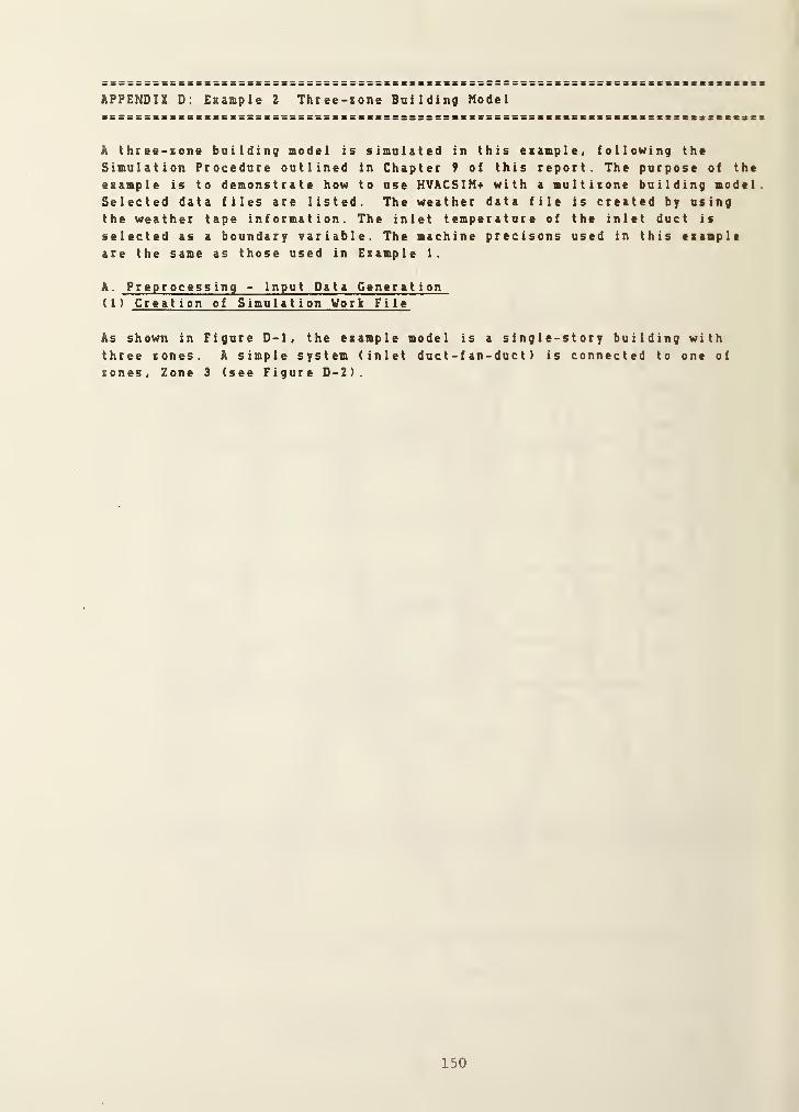
APPENDIX D: Esasple 2 Three-tone Building Model
A three-tone building model is simulated in this example, following the
Simulation Procedure outlined in Chapter 9 of this report. The purpose of the
example is to demonstrate how to use HVACSIH-i- with a multitone building model.Selected data files are listed. The weather data file is created by usingthe weather tape information. The inlet temperature of the inlet duct is
selected as a boundary variable. The machine precisons used in this exampleare the same as those used in Example 1.
A . Preprocessing - Input Data Generation( 1 ) Creation of Simulation Work File
As shown in Figure D-1, the example model is a single-story building withthree zones. A simple system (inlet duct -f an-duc t ) is connected to one of
zones, Zone 3 (see Figure D-2).
150

North
wall
Southwail
East wa!S
Window
TOP V3EW
Window
Figure D-1. A three-zone model
TY3 TY1 TY2 TY52 TY2
Figure D-2. A simple system (fan and ducts) for Zone 3
151

* Initial Conditions of State Variables
PI Zone air pressure, gage ( IZN=1
)
0 . 0 kPa
P2 Zone air pressure, gage ( IZN=2
)
0 . 0 kPd
P3 Zone air pressure. gage ( IZN=3
)
0 . 3 kPa
P4 Supply air pressure, gage (IZN=1) 0 . 0 kPa
P5 Supply air pressure, gage (1ZN=2> 0 0 kPa
P6 Supply air pressure, gage (IZN=3) 0 . 5 kPa
P7 Inlet pressure of the inlet duct 0 0 kPa
P8 Outlet pressure of the inlet duct -0. 8 kPa
P9 Outlet pressure of the f an 1 ,. 0 kPa
PIO Out let pressure of the eshaust duct -0. 5 kPa
PI 1 Outdoor air barometric pressure 0 . 0 kPa
Ml Supply air mass flow rate (1ZN=1) 0 . 0 k g / s
M2 Supply air mass flow rate (IZN=2) 0 . 0 kg/s
M3 Supply air mass flow rate (IZN=3) 2 . 5 kg/ s
T1 Inner surface t emp 0 f roof (IZN=1
)
20 . 0 C
T2 Inner surface t emp 0 f floor 20 . 0 C
T3 Inner surface t emp 0 f west wall 20 . 0 C
T4 Inner surface t emp 0 f south wall 20 . 0 C
T5 Inner surface t emp 0 f east wall 20 . 0 C
T6 Inner surf ace t emp 0 f north wall 20 0 C
T7 Inner surface t emp 0 f north window 20 . 0 C
T8 Inner surf ace t emp 0 f roof (IZN=2) 20 . 0 C
T9 Inner surface t emp 0 f floor 20 . 0 C
TIO Inner surface t emp 0 f west wall 20 0 C
T1 1 Inner surface t emp 0 f south wall 20 0 C
T12 Inner surface t emp 0 f east wall 20 0 C
T1 3 Inner surface t emp 0 f north wall 20 . 0 C
T14 Inner surf ace t emp 0 f roof (IZN=3) 20 0 C
T15 Inner surface t emp 0 f floor 20 0 C
T16 Inner surface t emp 0 f west wall 20 0 C
T17 Inner surface t emp 0 f south wall 20 0 C
T18 Inner surf ace t emp 0 f east wall 20 0 C
T19 Inner surface t emp 0 f north wall 20 . 0 C
T20 Inner surface t emp 0 f south window 20 0 C
T2 1 Ground t emp
.
15 0 c
T22 Mean radiant t empe r a t u r e (I ZN= 1
)
20 0 c
T23 Mean radiant temperature (IZN=2) 20 0 c
T24 Mean radiant temperature (IZN=3) 20 0 c
T25 Zone air dr y- bulb t emp . ( IZN=1
)
20 0 c
T26 Zone air dry- bulb t emp ( IZN=2
)
20 0 c
T27 Zone air dry- bulb t emp . ( IZN=3
)
20 0 c
T28 Supply air t emp
.
(IZN=1
)
20 0 c
T29 Supply air temp. ( IZN=2 ) 20 0 c
T30 Supp 1 y air t emp
.
( IZN = 3 ) 20 0 c
T31 Inlet air t emp . o f the inlet duct (B.C) 20 0 c
T32 Outdoor air dry-bulb temp. 20 0 c
T33 Outlet air temp, of the inlet duct 20 0 c
Cl Numb er of people ( IZN=i
)
1 0
C2 Equipment utilization coefficient 1 0
C3 Light utilization coefficient 1 0
C4 Shaded fraction of outer surface 0 0
C5 Number of people ( IZN=2
)
1 0
152

Z6 Equipment utilization coefficient 1 . 0
C7 Light utilization coefficient 1 . 0
C8 Shaded fraction of outer surface 0 . 0
C9 Number of people (1ZN=3) 1 0
CIO Equipment utilization coefficient 1 . 0
Cl 1 Light utilization coefficient 1 . 0
C12 Shaded fraction of outer surface 0 . 0
R1 Fan roataional speed 60 . 0 r e V / s
Q1 Convective heat gain from surfaces It 0 . c kV
Q2 Short wave radiant heat gain 0 . 0 fcW
Q3 Long wave radiant heat gain 0 . 0 kUQ4 Convective heat gain from surfaces ( IZN=2) 0 . 0 kWQ5 Short wave radiant heat gain 0 . 0 kV
Q6 Long wave radiant heat gain 0 . 0 kWQ7 Convective heat gain from surfaces < IZN=3
)
0 . 0 kV08 Short wave radiant heat gain 0 . 0 kV/
09 Long wave radiant heat gain 0 . 0 kW
OlO Fan power consumption 0 . 0 kV01 1 Direct solar radiation 0 . 0 kV012 Diffuse solar radiation 0 . 0 kV01 3 Total horizontal solar radiation 0 . 0 kW
HI Zone air humidity ratio (IZNrl) 0.0074H2 Zone air humidity ratio (IZN=2) 0 . 0074
H3 Zone air humidity ratio (IZH=3) 0.0074H4 Supply air humidity ratio (IZN=1) 0.0074H5 Supply air humidity ratio (IZM=2) 0.0074H4 Supply air humidity ratio (1ZN=3) 0.0074H7 Outdoor air humidity ratio 0 . 0
a.'
153

* Eiecution of HVACGEN
HVACGEN - Simulation GENeration ProgramVersion 1.8 (08-16 1985)
Choose from the list below;
CReate ( S Imu 1 a t i on , Block , UNi t
)
EDit (Slmulat ion.UNit
)
View ( Slmu 1 at i on , Block , UNi t
)
HElp
ENd
Selection ?
VI
View a
;
SImulat ion
Block MUNitEnter Selection
SI
Enter the filename (Maiimum of 8 characters)THRIZONEreading from work file....INITIAIIZING TYPES INFORMATION...
What part of the simulation would you like to view
All the simulation information (for documentation)
STructure (superblock , block , and unit Information)
VAriable initial values
ERror tolerances, variable scan and freese options
Boundary variables
REported variables
continue with the previous menu
Al
THREE ZONE BUIIDING MODEl --A SINGIE STORY BUllDING
SUPERBIOCK 1
BIOCK 1
UNIT 1 TYPE 50 - ZONE ENVEIOPE
154

UNIT 2 TYPE 51 - BUILDING SURFACE
UNIT 3 TYPE 51 - BUILDING SURFACEUNIT 4 TYPE 51 - BUILDING SURFACEUNIT 5 TYPE 51 - BUILDING SURFACEUNIT 6 TYPE 51 - BUILDING SURFACEUNIT 7 TYPE 51 - BUILDING SURFACE.
UNIT 8 TYPE 51 - BUILDING SURFACEBLOCK 2
UNIT 9 TYPE 50 - ZONE ENVELOPSUNIT 10 TYPE 51 - BUILDING SURFACEUNIT 11 TYPE 51 - BUILDING SURFACEUNIT 12 TYPE 51 - BUILDING SURFACEUNIT 13 TYPE 51 - BUILDING SUSP^'CE
UNIT 14 TYPE 51 - BUILDING £UP7F^ACE
UNIT 15 TYPE 51 - BUILDING SURFACEUNIT 16 TYPE 51 - BUILDING SURFACE
BLOCK 3
UNIT 17 TYPE SO - ZONE ENyFlOrF.
UNIT 18 TYPE 5 1 - BUILDING SURFACEUNIT 19- TYPE 51 - BUILDING SURFACEUNIT 20 TYPE 51 - BUILDING SURFACEUNIT 21 TYPE 51 - BUILDING SURFACEUNIT 22 TYPE 51 - BUILDING SURFACEUNIT
BLOCK 4
23 TYPE 51 - BUILDING SURFACE
UNIT 31 TYPE 53 - LEATHER INPUT
SUPERBLOCK 2
BLOCK 5
UNIT 24 TYPE 52 - ZONE KODELBLOCK 6
UNIT 25 TYPE 52 - ZONE MODELBLOCK 7
UNIT 26 TYPE 52 - ZONE MODELBLOCK 8
UNIT 27- TYPE 3 - INLET CONDUIT (DUCT OF.
UNIT 28 TYPE 1 - FAN OR Pim?UNIT 29 TYPE 2 - CONDUIT (DUCT OR PIPE)UNIT 30 TYPE 2 - CONDUIT (DUCT OR PIPE)
UNIT 1 TYPE 50
ZONE ENVELOPE
1 INPUTS;
TEMPERATURE 27 - TIA: Zone ir dry -bn lb taiaperaturePOWER 8 - QISV: I n i G :• nal (short wave) radiant gainPOWER 9 - QILW: In i 0 r nil (Ion -3 wavs) radiant gainTEMPERATURE 14 - TIS( 1 ) Inner 5 w r ! n c e temper a tareTEMPERATURE 15 - TIS(2) Inner surface temperatureTEMPERATURE 16 - TIS< 3) Inner surface temperatureTEMPERATURE 17 - TIS( 4) Inner surface temperatureTEMPERATURE 18 - TIS(5) Inner scr face temperatureTEMPERATURE 19 - TIS(6) Inner 5 u r I A C 6 t emper a t ur c
TEMPERATURE 20 - TIS(7) Inner surface t empexa t ur e
TEMPERATURE 20 - TIS(8) Inner surface temperatureTEMPERATURE 20 - TIS(9) inner surface t emper a t ur e
TEMPERATURE 20 - TIS( 10) : Inn. T surface temperature
2 OUTPUTS
;
155

TEMPERATUREPOWER
24 - TMR ; Mean radiant temperature7 - QVALL; Convective heat gain from surfaces
PARAMETERS
;
3. 000007 .00000
IZN:
NS;
UNIT 2 TYPE 51
BUILDING SURFACE
1 INPUTS
:
TEMPERATURE 27 -
TEMPERATURE 24 -
TEMPERATURE 14 -
CONTROL 12 -
2 OUTPUTS
:
TEMPERATURE 14 -
POWER 0 -
3 PARAMETERS:3. 00000 IZN:
1 .00000 ID:
2 . 00000 lEXPOS1 .00000 ISTR;
37.2100 AS:
0 . 000000 ORIENT0.000000 TILT:0 . 200000 GRF :
1 . 00000 IROFS;
0 .600000 ABSOS:0 650000 ABSIS:0 .900000 EMITIS0.000000 TRANSM0 . 000000 SC ;
Identification number of tone
Number of surfaces of tone
TIA: Indoor air dry-bulb temperatureTMR: Mean radiant temperatureTOSINF: Outer surface temp, of uneiposed wallFSHADW; Shaded fraction of eiposed surface
SOLINT:Inner surface temperatureIntegrated solar influi on surface
Identification number of toneIdentification number of surface0=U/in tone, isbetw. tones , Zstiposed to sun
Identification number of the constructSurface area (m2)
Atimuth angle of normal to surface i southTilt angle: flat roofzO, flooraisO (degree)Ground reflectivity (-)
Outer surface roughness indci: l>stucco,...Solar absorptance of outer surface (-)
Short wave absorptance of inner .sur f ace (-
)
Emissivity of the inner surface (-)
Transmittance of the glass window (-)
Shading coeff. of the glass window (-)
UNIT 3 TYPEBUILDING SURFACE
SI
1 INPUTS;
TEMPERATURE 27 - TIA;TEMPERATURE 24 - TMR:TEMPERATURE 21 - TOSINFCONTROL 12 - FSHADW
OUTPUTS
:
TEMPERATURE 15 - TIS:POWER 0 - SOLINT
Indoor air dry-bulb temperatureMean radiant temperatureOuter surface temp, of uneiposed wall
Inner surface temperatureIntegrated solar influi on surface
PARAMETERS:3.00000 IZN: Identification number of lone
2 .00000 ID; Identification number of surface1 . 00000 lEXPOS: OsW/in tone, l>betw. tones , 2aeiposed to sun
2 .00000 ISTR: Identification number of the construct37.2100 AS: Surface area (m2)
0 . 000000 ORIENT: Aiimuth angle of normal to surface ( south180 . 000 TILT: Tilt angle; flat roof«0, flooralSO (degree)
0 . 200000 GRF: Ground reflectivity (-)
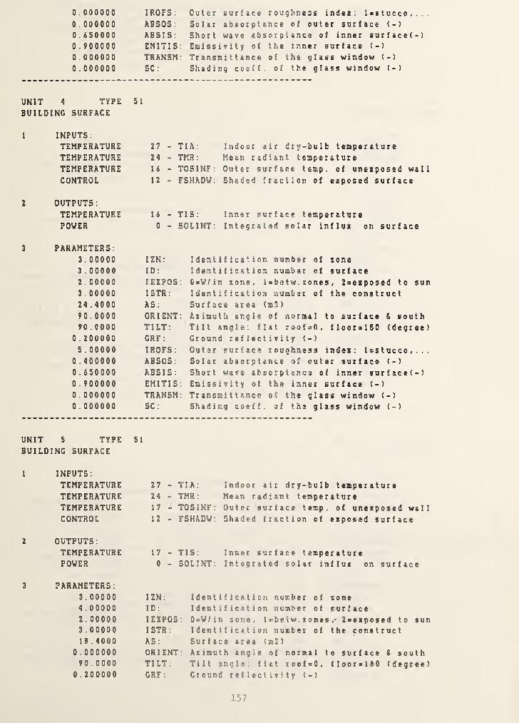
UNIT
0 . 000000
0 . 0000000 .6500000 .9000000 . 0000000 . 000000
IROFS:
ABSOS
:
ABSIS;EMITISTRANSMSC :
4 type 51
NG SURFACE
INPUTS
;
TEMPERATURE 27 -
TEMPERATURE 24 -
TEMPERATURE 16 -
CONTROL 12 -
OUTPUTS:TEMPERATURE 16 -
POWER 0 -
PARAMETERS:3. 00000 IZN;
3 .00000 ID:
2 . 00000 lEXPOS3 . 00000 ISTR:
24 . 4000 AS:
90.0000 OR I ENT90 . 0000 TILT:
0 .200000 GRP;
5 . 00000 IROFS:
0 . 400000 ABSOS:0 .650000 ABSIS:0 .900000 EMITIS0 . 000000 TRANSM0 . 000000 SC ;
Outer surface roughness indea : Isstucco,..Solar absorptance of outer surface (-)
Short wave absorptance of inner surface(-)Emissivity of the inner surface <-)
Transmittance of the glass window (-)
Shading coeff. of the glass window (-)
TIA; Indoor air dry-bulb temperatureTMR : Mean radiant temperatureT05INF: Outer surface temp, of uneiposed wall
- FSHADU: Shaded fraction of esposed surface
TIS: Inner surface temperatureon surface
Identification number of zoneIdentification number of surface0=V/in zone, i=betw. zones , 2sezposed to sunIdentification number of the constructSurface area (m3)
Azimuth angle of normal to surface fi southTilt angle: fiat roof^O, floorslSO (degree)Ground reflectivity (-)
Outer surface roughness indei : Isstucco,...Solar absorptance of cuter surface (-)
Short wave absorptance of inner snrface(-)Emissivity of the inner surface (-)
Transmittance of the glass window (-)
Shading coeff. of the glass window (-)
UNIT 5 TYPE 51
BUILDING SURFACE
1 INPUTS;
TEMPERATURE 27 - TIA: Indoor air dry-bulb temperatureTEMPERATURE 24 - TMR: Mean radiant temperatureTEMPERATURE 17 - TOSINP; Outer surface temp. of uneiposed wallCONTROL 12 - FSHADW: Shaded fraction of eipossd surface
OUTPUTS
:
TEMPERATURE 17 - TIS: Inner surface temperaturePOWER 0 - SOLINT; Integrated solar influx on surface
PARAMETERS:3.00000 IZN: Identification number of zone4 .00000 ID; Identification number of surface2 . 00000 lEXPOS: 0=W/in zone, Icbetw. zones , 2Beiposcd to sun3 .00000 I STR
;
Identification number of the constructIB . 4000 AS : Surface area (m2)
0 . 000000 ORIENT: Azimuth angle of normal to surface S south90 . 0000 TILT: Tilt angle : flat r oof bO , f I oor > 180 ( degree
)
0 . 200000 GRP: Ground reflectivity (-)
157

UNIT
5 . 00000
0 . 4000000 . dSOOOO0 .900000
0 . 0000000 . 000000
IROFS:
ABSOS :
ABSIS:EMITISTRANSMSC :
6 TYPE 51
NG SURFACE
INPUTS
:
TEMPERATURE 27 -
TEMPERATURE 24 -
TEMPERATURE 18 -
CONTROL 12 -
OUTPUTS
:
TEMPERATURE 18 -
POWER 0 -
PARAMETERS:3 . 00000 IZN:
S .00000 ID :
2 . 00000 lEXPOS3.00000 ISTR:
24 . 4000 AS:
270 .000 OR I ENT90.0000 TILT:
0 . 200000 GRF:
5 . 00000 IROFS:
0 . 400000 ABSOS:0. 6S0000 ABSIS:0 .900000 EMITIS0.000000 TRANSM0 . 000000 SC:
Outer surface roughness indei; l=stucco,..Solar absorptance of outer surface (-)
Short wave absorptance of inner surface(-)Emissivity of the inner surface (-)
Transmittance of the glass window (-)
Shading coeff. of the glass window (-)
TIA: Indoor air dry-bulb temperatureTMR ; Mean radiant temperatureTOSINF: Outer surface temp, of uneiposed wallFSHADV: Shaded fraction of eiposed surface
TIS: Inner surface temperatureon surface
Identification number of loneIdentification number of surface0=W/in tone, 1 sbe tw . t ones , 2ceiposed to son
Identification number of the constructSurface area (m2)
Atimuth angle of normal to surface & southTilt angle: flat roofsO, floorclSO (degree)Ground reflectivity (-)
Outer surface roughness indei: l>stucco,...Solar absorptance of outer surface (-)
Short wave absorptance of inner surface(-)Emissivity of the inner surface (-)
Transmittance of the glass window (-)
Shading coeff. of the glass window (-)
UNIT 7 TYPEBUILDING SURFACE
SI
1 INPUTS:
TEMPERATURE 27 - TIA:TEMPERATURE 24 - TMR:TEMPERATURE 11 - TOSINFCONTROL 12 - FSHADW
OUTPUTS
:
TEMPERATURE 19 - TIS:POWER 0 - SOLINT
Indoor air dry-bulb temperatureMean radiant temperature
Inner surface temperatureIntegrated solar influi on surface
PARAMETERS:3. 00000 IZN: Identification number of zone
6 .00000 ID: Identification number of surface1 . 00000 lEXPOS: OsW/in zone, labetw. zones ,• 2Beiposed to sun
5 . 00000 ISTR: Identification number of the construct24 . 4000 AS: Surface area (m2)
0 . 000000 ORIENT: Azimuth angle of normal to surface i south90 .0000 TILT: Tilt angle: flat roof>0, floorslBO (degree)
0 . 200000 GRF: Ground reflectivity (-)
158
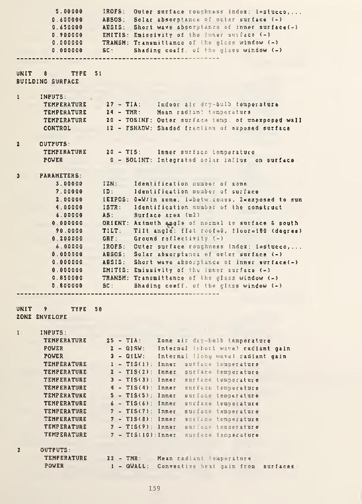
S . 00000
0 .6000000. 6S00000 .9000000 .0000000 . 000000
IROFS: Outer surface roughness indes; l=stucco,...ABSOS; Solar absorptance of outer surface (-)
ABSIS; Short wave absorptance of inner surface(-)EMITIS: Emissivity of the inner surface (-)
TRANSM: Transni t tance of the giass window (-)
SC: Shading coeff. of the glass window (-)
UNIT 8 TYPE 51
BUILDING SURFACE
I INPUTS;TEMPERATURE 27 - TIA:
TEMPERATURE 24 - TMR ;
TEMPERATURE 20 - TOSINFCONTROL 12 - FSHADW
OUTPUTS
;
TEMPERATURE 20 - TIS;
POWER 0 - SOLINT
Indoor air dry -bulb temperatureMean radian; t saper a t ur a
Outer surface temp of unexposed wallShaded fraction of exposed surface
Inner surface temperatureIntegrated solar influx on surface
3 PARAMETERS:3.00000 IZN; Identification number of s one
7 .00000 ID; Identification number of surface2.00000 lEXPOS: OsW/in sone, l=betw . sones , 2=exposed to sun4 .00000 ISTR; Identification number of the construct6.00000 AS: Surface area (m2)
0 . 000000 ORIENT; Azimuth ^gle of normal to surface S south90.0000 TILT: Tilt angle': flat ro&fsO, flcorsl80 (degree)
0 . 200000 GRP: Ground reflectivity (-)
6 . 00000 IROFS; Outer surface roughness index : Isstucco , . . .
0 . 000000 ABSOS: Solar absorptance of outer surface (-)
0 .000000 ABSIS: Short wave absorptance of inner surface(-)0 . 000000 EMITIS; Emissivity of the inner surface (-)
0.850000 TRANSM; Transmittance of the glass window (-)
0 . 800000 SC ; Shading coeff. of the gl ass window (-)
UNIT 9 TYPE 50
ZONE ENVELOPE
1 INPUTS:
TEMPERATURE 25 - TIA: Zone air dry -bulb temperaturePOWER 2 - QISW: Internal (short wave) radiant gainPOWER 3 - QILW; Internal (long wave) radiant gainTEMPERATURE 1 - TIS( 1
)
Inner surface temperatureTEMPERATURE 2 - TIS(2) Inner surface temperatureTEMPERATURE 3 - TIS(3) Inner surface temperatureTEMPERATURE 4 - TIS(4) Inner surface temperatureTEMPERATURE 5 - TIS(5) Inner surface t empe r a t ur e
TEMPERATURE 6 - TIS(6) Inner surface temperatureTEMPERATURE 7 - TIS(7) Inner surface t empe r a t nr e
TEMPERATURE 7- TIS(8) Inner surface temperature
TEMPERATURE 7 - TIS(9) Inner s u c ;; a c e temperatureTEMPERATURE 7 - TIS( 10) : Inner surface temperature
2 OUTPUTS:TEMPERATURE 22 - TMR : Mean radiant temperaturePOWER 1 - QWALL; Convective heit gain from sur t aces
159

PARAMETERS:1 . 000007 . 00000
IZN;
NS:
UNIT 10 TYPE 51
BUILDING SURFACE
1 INPUTS;
TEMPERATURE 25 -
TEMPERATURE 22 -
TEMPERATURE 1 -
CONTROL 4 -
2 OUTPUTS;TEMPERATURE 1 -
POWER 0 -
3 PARAMETERS:1 . 0000.0 IZN:
1 .00000 ID:
2 . 00000 lEXPOS1 .00000 ISTR:
37.2100 AS:
0 . 000000 ORIENT0.000000 TILT:0 . 200000 GRF;
1.00000 IROFS:0 . 600000 ABSOS:0 . 650000 ABSIS:0 . 900000 EMITIS0.000000 TRANSM0 . 000000 SC:
Identification number of toneNumber of surfaces of tone
TIA: Indoor air dry-bulb temperatureTNR: Mean radiant temperatureTOSINF: Outer surface temp, of uneiposed wall
FSHADV: Shaded fraction of eiposed surface
TIS; Inner surface temperatureSOLINT: Integrated solar influi on surface
Identification number of tone
Identification number of surface0=W/in tone, Isbetw. tones , 2sciposcd to sun
Identification number of the constructSurface area (m2)
Atimuth angle of normal to surface S south
Tilt angle; flat roofsO, floor«160 (degree)Ground reflectivity (-)
Outer surface roughness indei; Isstucco,...Solar absorptance of outer surface (-)
Short wave absorptance of inner surface(-)Emissivity of the inner surface (-)
Transmittance of the glass window (-)
Shading coeff. of the glass window (-)
UNIT 11 TYPEBUILDING SURFACE
51
1 INPUTS;
TEMPERATURE 25 - TIA:TEMPERATURE 22 - TMR;TEMPERATURE 21 - TOSINFCONTROL 4 - FSHADW
OUTPUTS
:
TEMPERATURE 2 - TIS:POWER 0 - SOLINT
Indoor air dry-bulb temperatureMean radiant temperature
Inner surface temperatureon surface
PARAMETERS:1 . 00000 IZN: Identification number of tone
2 . 00000 ID; Identification number of surface
1 . 00000 I EXPOS : OsW/in tone, Isbetw. tones , 2>eiposed to sun
2 .00000 ISTR; Identification number of the construct
37.2100 AS; Surface area (m2)
0 .000000 ORIENT; Atimuth angle of normal to-surface 6 south
180 . 000 TILT. Tilt angle; flat roof-O, flooralSO (degree)
0 . 000000 GRF: Ground reflectivity (-)
0.000000 IROFS: Outer surface roughness indei lastucco,0 . 000000 ABSOS: Solar absorptance of outer surface (-)
0.650000 ABSIS: Short wave absorptance of inner surface(-)
160
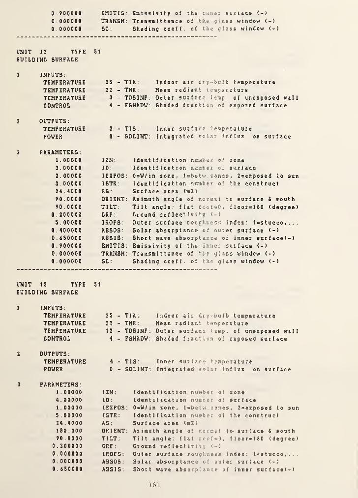
0.900000 EMITIS: Emissivity of the inner surface (-)
0.000000 TRANSM: Transmittance of the glass window (-)
0.000000 SC: Shading coeff. of the glass window (-)
UNIT 12 TYPE 51
BUILDING SURFACE
1 INPUTS:TEMPERATURE 25 - TIA:
TEMPERATURE 22 - TMR:
TEMPERATURE 3 - TOSINFCONTROL 4 - FSHADW
2 OUTPUTS
:
TEMPERATURE 3 - TIS:
POWER 0 - SOLINT
Indoor air dry-hulb temperatureMean radiant temperatureOuter surface temp, of uneaposed wallShaded fraction of exposed surface
Inner surface temperatureIntegrated solar influs on surface
3 PARAMETERS:1 . 00000 IZN: Identification numbsr of zone
3 .00000 ID: Identification number of surface
2.00000 lEXPOS: 0=V/in zone, l=betw. nones , 2sesposed to sun
3 .00000 ISTR: Identification number of the construct24 . 4000 AS: Surface area (m2)
90 . 0000 ORIENT: Azimuth angle of normal to surface S south90 . 0000 TILT: Tilt angle: flat lootsQ, floorsiSO (degree)
0 . 200000 GRF: Ground reflectivity (-)
5 . 00000 IROFS: Outer surface roughness indez : l = stucco «...
0 . 400000 ABSOS: Solar absorptance of out er surface (-)
0.650000 ABSIS: Short wave absorptance of inner surface(-)0 . 900000 EMITIS: Emissivity of the inner surface (-)
0.000000 TRANSM: Transmittance of the gla ss windcw (-)
0 . 000000 SC: Shading coeff. of the glass window (-)
UNIT 13 TYPE 51
BUILDING SURFACE
1 INPUTS:TEMPERATURE 25 - TIA: Indoor air dry-bulb temperatureTEMPERATURE 22 - TMR: Mean radiant temperatureTEMPERATURE 13 - TOSINF: Outer surface temp. of unezposed wallCONTROL 4 - FSHADW: Shaded fraction of exposed surface
OUTPUTS
:
TEMPERATURE 4 - TIS: Inner surface temperaturePOWER 0 - SOLINT: Integrated solar influz on surface
PARAMETERS:1 . 00000 IZN: Identification number of zone4 .00000 ID: Identification number of surface1 . 00000 lEXPOS: 0=W/in zone, l=betw. zones , 2sezposed to sun5 . 00000 ISTR: Identification number of the construct24 . 4000 AS: Surface area (m2)
180 . 000 ORIENT: Azimuth angle of normal to- surface i south90 . 0000 TILT: Tilt ang 1 e: flat roofsO, floorslSO (degree)
0 .200000 GRF : Ground reflectivity (-)
0 .000000 IROFS Outer surface toughness indez: l>stucco,...0 . 000000 ABSOS Solar absorptance of outer surface (-)
0.650000 ABSIS Short wave absorptance of inner sur f ace ( -
)
161

0 . 9000000.0000000 . 000000
EMITISTRANSMSC :
UNIT 14 TYPE 51
BUILDING SURFACE
1 INPUTS:
TEMPERATURE 25 -
TEMPERATURE 22 -
TEMPERATURE 5 -
CONTROL 4 -
2 OUTPUTS
:
TEMPERATURE 5 -
POWER 0 -
3 PARAMETERS:1 . 00000 IZN:
5 .00000 ID:
2 . 00000 lEXPOS3 . 00000 ISTR:
24 . 4000 AS:
270 .000 ORIENT90 . 0000 TILT:
0 . 200000 GRF:
5 . 00000 IROFS:
0 . 400000 ABSOS:0 . 650000 ABSIS:0 .900000 EMITIS0.000000 TRANSM0 . 000000 SC :
Shading coeff. of the glass window (-)
TIA: Indoor air dry-bulb temperatureTMR ; Mean radiant temperatureTOSINF; Outer surface temp, of uneiposed wallFSHADV; Shaded fraction of eiposed surface
TIS: Inner surface temperatureon surface
Identification number of toneIdentification number of surface0=V/in sone, 1 sbe tw . tones , 2«eiposed to sun
Identification number of the constructSurface area (m2)
Aiimuth angle of normal to surface S southTilt angle: flat roofsO, floorsieo (degree)Ground reflectivity (-)
Outer surface roughness indei: l>stucco,...Solar absorptance of outer surface (-)
Short wave absorptance of inner surface(-)Emissivity of the inner surface (-)
Transmittance of the glass window (-)
Shading coeff. of the glass window (-)
UNIT 15 TYPE 51
BUILDING SURFACE
1
2
3
INPUTS;
TEMPERATURE 25 - TIA:
TEMPERATURE 22 - TMR;TEMPERATURE 6 - TOSINFCONTROL 4 - FSHADW
OUTPUTS;TEMPERATURE 6 - TIS:POWER 0 - SOLINT
Indoor air dry-bulb temperatureMean radiant temperatureOuter surface temp, of uneiposed wall
Shaded fraction of eiposed surface
Inner surface temperatureIntegrated solar influi on surface
PARAMETERS:1 . 00000 IZN: Identification number of tone
6.00000 ID: Identification number of surface
2.00000 lEXPOS: OsW/in sonc, 1 abe t w . t ones , Zsesposed to son
3 .00000 ISTR: Identification number of t he cons t rue t
18 .4000 AS; Surface area (m2)
1 80 .000 ORIENT: Aiimuth angle of normal t 0 - sur f ace ( south
90 . 0000 TILT; Tilt angle; flat roof>0, floorallO (degree)
0 . 200000 GRF ; Ground reflectivity (-)
5 . 00000 IROFS: Outer surface roughness indes lastucco,0 . 400000 ABSOS; Solar absorptance of outer surface (-)
0.650000 ABSIS: Short wave absorptance of inner surface(-)
162

0.900000 EMITIS: Emissivity of the inner surface (-)
0.000000 TRANSM: Transmittance of the glass window (-)
0.000000 SC: Shading coeff. of the glass window (->
UNIT 16 TYPE 51
BUILDING SURFACE
1
2
INPUTS:TEMPERATURETEMPERATURETEMPERATURECONTROL
25 - TIA:22 - TMR:7 - TOSINF:4 - FSHADV:
Indoor air dry-bulb temperatureMean radiant temperatureOuter surface temp, of unezposed wall
Shaded fraction of eaposed surface
OUTPUTS
:
TEMPERATUREPOWER
7 - TIS:
0 - SOLINT:Inner surface temperatureIntegrated solar influx on surface
3 PARAMETERS:1.00000 IZN:
7 .00000 ID:
2.00000 lEXPOS4 . 00000 I STR
:
6 . 00000 AS:
1 80 . 000 OR I ENT90 . 0000 TILT:
0 . 200000 GRF:
6 . 00000 IROFS:0 . 000000 ABSOS:0.000000 ABSIS:0 .000000 EMITIS0.850000 TRANSM0 .800000 SC:
Identification number of zoneIdentification number of surface0=V/in zone, l=betw. zones , Zsezposed to sunIdentification number of the constructSurface area (m2)
Azimuth angle of normal to surface & southTilt angle: flat roof=0, floor=180 (degree)Ground reflectivity (•)
Outer surface roughness indez: Isstucco,...Solar absorptance of outer surface (-)
Short wave absorptance of inner surface(-)Emissivity of the inner surface (-)
Transmittance of the glass window (-)
Shading coeff. of the glass window (-)
163
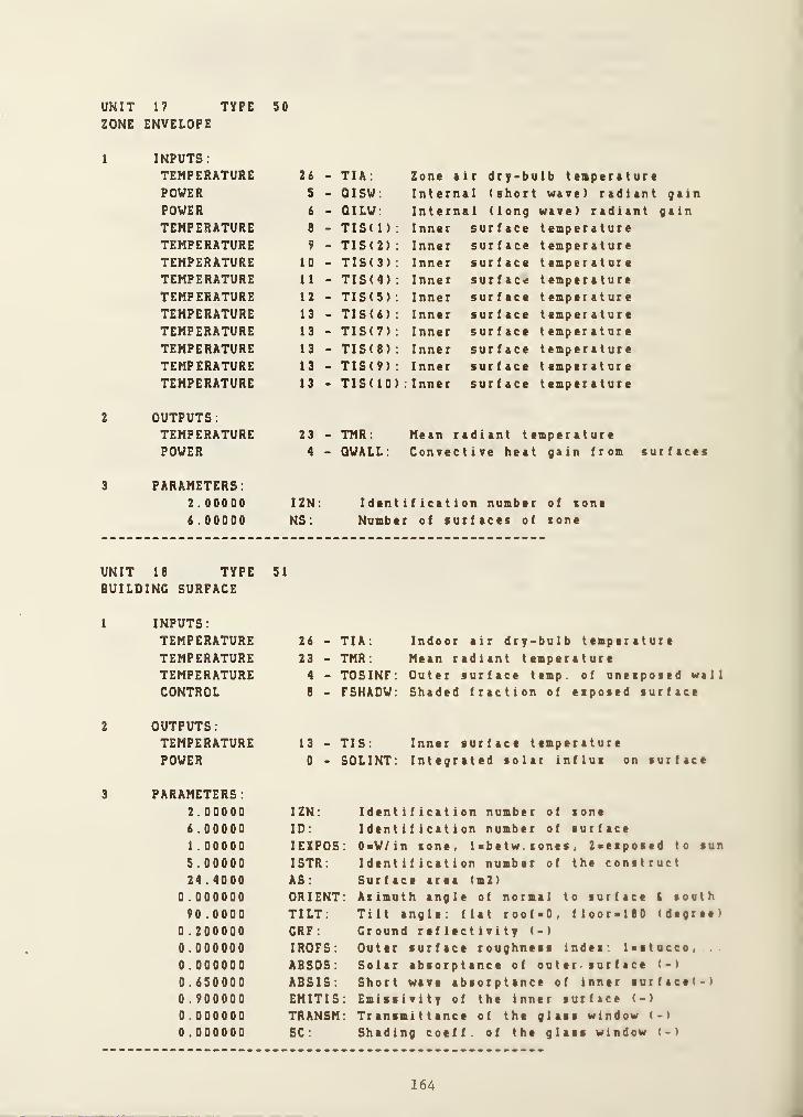
UNIT 17 TYPE 50
ZONE ENVELOPE
1 INPUTS:TEMPERATURE 26 - TIA: Zone air dry-bulb temperaturePOWER 5 - QISW: Internal (short wave) radiant gainPOWER 6 - QILW: Internal (long wave) radiant gainTEMPERATURE 8 - TIS( 1
)
Inner surface temperatureTEMPERATURE 9 - TIS(2) Inner surface t emper a t ur e
TEMPERATURE 10 - TIS( 3) Inner surface temperatur e
TEMPERATURE 11 - TIS(4) Inner surface temperatureTEMPERATURE 12 - TIS(5) Inner surface temperatureTEMPERATURE 13 - TIS(6) Inner surface temperatureTEMPERATURE 13 - TIS(7) Inner surface t emper a t ur e
TEMPERATURE 13 - TIS(8) Inner surface temperatureTEMPERATURE 13 - TIS(9) Inner surface t emper a t ur e
TEMPERATURE 13 - TIS( 10) : Inner surface temperature
OUTPUTS
:
TEMPERATURE 23 - TMR: Mean radiant temperaturePOWER 4 - QWALL; Convective heat gain from surfaces
PARAMETERS:2.00000 IZN Identification number of tone
6 . 00000 NS: Number of surfaces of tone
UNIT 18 TYPE 51
BUILDING SURFACE
1 INPUTS:
TEMPERATURETEMPERATURETEMPERATURECONTROL
2 OUTPUTS
:
TEMPERATUREPOWER
3 PARAMETERS:2.000006.000001 . 000005 . 0000024 . 4000
0 . 00000090.0000
0 . 2000000.0000000 . 0000000.6500000 . 9000000.0000000.000000
26 - TIA: Indoor air dry-bulb tamparatur#
23 - TMR: Mean radiant teaparature4 - TOSINF: Outer surface tamp, of unaiposad wall
B - FSHAOV: Shaded fraction of eiposed surface
13 - TIS: Inner surface temperature
0 - SOLINT: Integrated solar influi on surface
IZN: Identification number of lone
ID: Identification number of surfacelEXPOS: OsV/in tone, l>betw. tones , Zaeiposed to sun
ISTR: Identification number of the construct
AS: Surface area (m2)
ORIENT: Atimuth angle of normal to surface 6 south
TILT: Tilt angle: flat roof«0, floor-lBO (degree)
CRF : Ground reflectivity (-)
IROFS: Outer surface roughness Indea: lastucco,
ABSOS: Solar absorptance of out er> sur f ace (-)
ABSIS: Short wave absorptance of inner surface(-)EMITIS: Emissivity of the inner surface (-)
TRANSM: Transmittance of the glass window (-)
SC: Shading coeff. of the glass window (-)
164

UNIT 19 TYPEBUILDING SURFACE
SI
1 INPUTS:TEMPERATURETEMPERATURETEMPERATURECONTROL
26 - TIA:
23 - TMR:
12 - TOSINF:8 - FSHADW:
Indoor air dry-bulb temperature
Mean radiant temperatureOuter surface temp, of unezposed wallShaded fraction of ezposed surface
OUTPUTS:TEMPERATUREPOWER
12 - TIS:
0 - SOLINT:Inner surface temperatureIntegrated solar influz on surface
3 PARAMETERS:2.00000 IZN: Identification number of zone
5 .00000 ID: Identification number of surface2.00000 lEXPOS: 0=V/in zone, l=betw. zones , 2sezposed to sun
3 . 00000 ISTR: Identification number of the construct24 . 4000 AS: Surface area (m2)
270 . 000 ORIENT: Azimuth angle of normal to surface & south90 . 0000 TILT: Tilt angle: flat roofsO, floorslSO (degree)
0 . 200000 GRF : Ground reflectivity (-)
S . 00000 IROFS: Outer surface roughness indez: l=stucco,...0 .400000 ABSOS: Solar absorptance of outer surface (-)
0.650000 ABSIS: Short wave absorptance of inner surface(-)0 . 900000 EMITIS: Emissivity of the inner surface (-)
0.000000 TRANSM: TransmitWnce of the glass window (-)
0 . 000000 SC: Shading coeff. of the glass window (-)
UNIT 20 TYPE 51
BUILDING SURFACE
1
2
3
INPUTS:
TEMPERATURETEMPERATURETEMPERATURECONTROL
26 - TIA:23 - TMR:
19 - TOSINF:8 - FSHADW:
Indoor air dry-bulb temperatureMean radiant temperatureOuter surface temp, of unezposed wallShaded fraction of ezposed surface
OUTPUTS
:
TEMPERATUREPOWER
11 - TIS:
0 - SOLINT:Inner surface temperatureIntegrated solar influz on surface
PARAMETERS:2.00000 IZN:
4 .00000 ID:
1 . 00000 lEXPOS5 .00000 ISTR:
24 .4000 AS:
180.000 ORIENT90 . 0000 TILT:
0 . 000000 GRF:0 .000000 IROFS:0 . 000000 ABSOS:0.650000 ABSIS:0 . 900000 EMITIS0.000000 TRANSM0 .000000 SC :
Identification number of zoneIdentification number of surfaceOsV/in zone, Isbetw. zones , 2=eiposed to sunIdentification number of the constructSurface area (m2)
Azimuth angle of normal to surface S southTilt angle: flat roof=0, floorsieO (degree)Ground reflectivity (-)
Outer surface roughness indei: 1 ss t ucco , . . .
Solar absorptance of out er . sur f ace (-)
Short wave absorptance of inner surface(-)Emissivity of the inner surface (-)
Transmittance of the glass window (-)
Shading coeff. of the glass window (-)
/
165
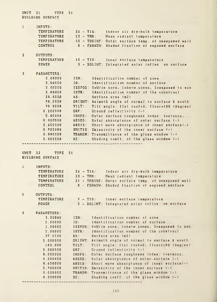
UNIT 21 TYPE 51
BUILDING SURFACE
INPUTS:
TEMPERATURE 26 -
TEMPERATURE 23 -
TEMPERATURE 10 -
CONTROL e -
OUTPUTS:TEMPERATURE 10 -
POWER 0 -
PARAMETERS:2.00000 IZN:
3 .00000 ID:
2.00000 lEXPOS3 .00000 ISTR;
24 . 400JD AS:
90 . 0000 ORIENT90 .0000 TILT;
0 . 200000 GRF:
5 . 00000 IROFS;0.400-000 ABSOS:0.650000 ABSIS;0 . 900000 EMITIS0.000000 TRANSM0 . 000000 SC;
TIA; Indoor air dry-bulb temperatureTMR; Mean radiant temperatureTOSINF: Outer surface temp, of uneipoied wallFSHADV; Shaded fraction of espoted lurface
TIS: Inner surface temperatureSOLINT; Integrated solar influi on surface
Identification number of tone
Identification number of surface0=V/in sone, Isbetw. tones , Zaeiposed to sun
Identification number of the constructSurface area (m2)
Azimuth angle of normal to surface & south
Tilt angle; flat roofsO, floorxlSO (degree)
Ground reflectivity (-)
Outer surface roughness index; Ixstucco,...Solar absorptance of outer surface (-)
Short wave absorptance of inner surface(-)Emissivity of the inner surface (-)
Transmittance of the glass window (-)
Shading coeff. of the glass window (-)
UNIT 22 TYPE 51
BUILDING SURFACE
1
2
3
INPUTS:
TEMPERATURETEMPERATURETEMPERATURECONTROL
26 - TIA:
23 - TMR:21 - TOSINF:8 - FSHADW:
Indoor air dry-bulb temperatureMean radiant temperatureOuter surface temp, of uneiposed wall
Shaded fraction of eiposed surface
OUTPUTS
:
TEMPERATUREPOWER
9 - TIS:
0 - SOLINT:Inner surface temperatureIntegrated solar influi on surface
PARAMETERS;2.00000 IZN:
2.00000 ID;
1 . 00000 lEXPOS2 . 00000 ISTR:
37 .2100 AS:
0 .000000 ORIENT180.000 TILT:
0 . 000000 GRF:0 . 000000 IROFS:0 . 000000 ABSOS:0.650000 ABSIS:0 . 900000 EMITIS0 . 000000 TRANSM0 . 000000 SC:
Identification number of toneIdentification number of surfaceOsV/in sone, l«betw. tones , 2>eipostd to sun
Identification number of the constructSurface area (m2)
Azimuth angle of normal to surface I south
Tilt angle: flat roof-O, flooralSO (degree)
Ground reflectivity (-)
Outer surface roughness indei; Ixstucco,
Solar absorptance of out er • sur f ace (-)
Short wave absorptance of inner surftce(-)Emissivity of the inner surface (-)
Transmittance of the glass window (-)
Shading coeff. of the glass window (-)
166

UNIT 23 TYPEBUILDING SURFACE
51
I
2
3
INPUTS:TEMPERATURE 26 -
TEMPERATURE 23 -
TEMPERATURE B -
CONTROL 8 -
OUTPUTS:TEMPERATURE 8 -
POWER 0 -
PARAMETERS:2 . 00000 IZN:
1 .00000 ID:
2.00000 lEXPOS1 .00000 ISTR:
37.2100 AS:
0 .000000 ORIENT0.000000 TILT:
0 . 200000 GRF :
1 . 00000 IROFS:
0 . 600000 ABSOS:
0.650000 ABSIS:0 . 900000 EMITIS0.000000 TRANSM0 .000000 SC:
TIA: Indoor air dry-bulb temperatureTMR ; Mean radiant temperatureTOSINF: Outer surface temp, of unezposed wallFSHADV: Shaded fraction of exposed surface
TIS: Inner surface temperatureSOLINT: Integrated solar influx on surface
Identification number of zone
Identification number of surface0=V/in zone, l=betw. zones , 2=exposed to sun
Identification number of the constructSurface area (m2)
Azimuth angle of normal to surface & southTilt angle: flat roof=0, floor=180 (degree)Ground reflectivity (-)
Outer surface roughness index: Isstucco,...Solar absorptance of outer surface (-)
Short wave absorptance of inner surface(-)Emissivity of the inner surface (-)
Transmittance of the glass window (-)
Shading coeff. of the glass window (-)
UNIT 31 TYPE 53
WEATHER INPUT
1
INPUTS:TEMPERATURE 32 - TAMB:ABS. HUMIDITY 7 - HUMRATPRESSURE 11 - PBAR:
POWER 11 - IDN:
POWER 12 - ISKY:
POWER 13 - IHOR:
Ambient (outdoor) air temperature (C)
Outdoor air humidity ratio (-)
Barometric pressure (kPa)
Direct normal solar radiation (V/m2)Diffuse (sky) solar radiation (V/m2)Total horizontal solar radiation (V/m2)
2
OUTPUTS:
3
PARAMETERS:32.0000 Index for ambient temperature (e.g. 5 if TAMB=T5)7.00000 Index for outdoor air humidity ratio11.0000 Index for barometric pressure11.0000 Index for direct normal solar radiation12.0000 Index for diffuse (sky) solar radiation13.0000 Index for total horizontal solar radiation
UNIT 24 TYPE 52
ZONE MODEL
1 INPUTS.
PRESSURE 3 - PIAG: Cage pressure of zone airTEMPERATURE 27 - TIA: Zone air dry- bn 1 b temperatur e
ABS. HUMIDITY 3 - WIA: Humi d i y ratio 0 f zone air
167
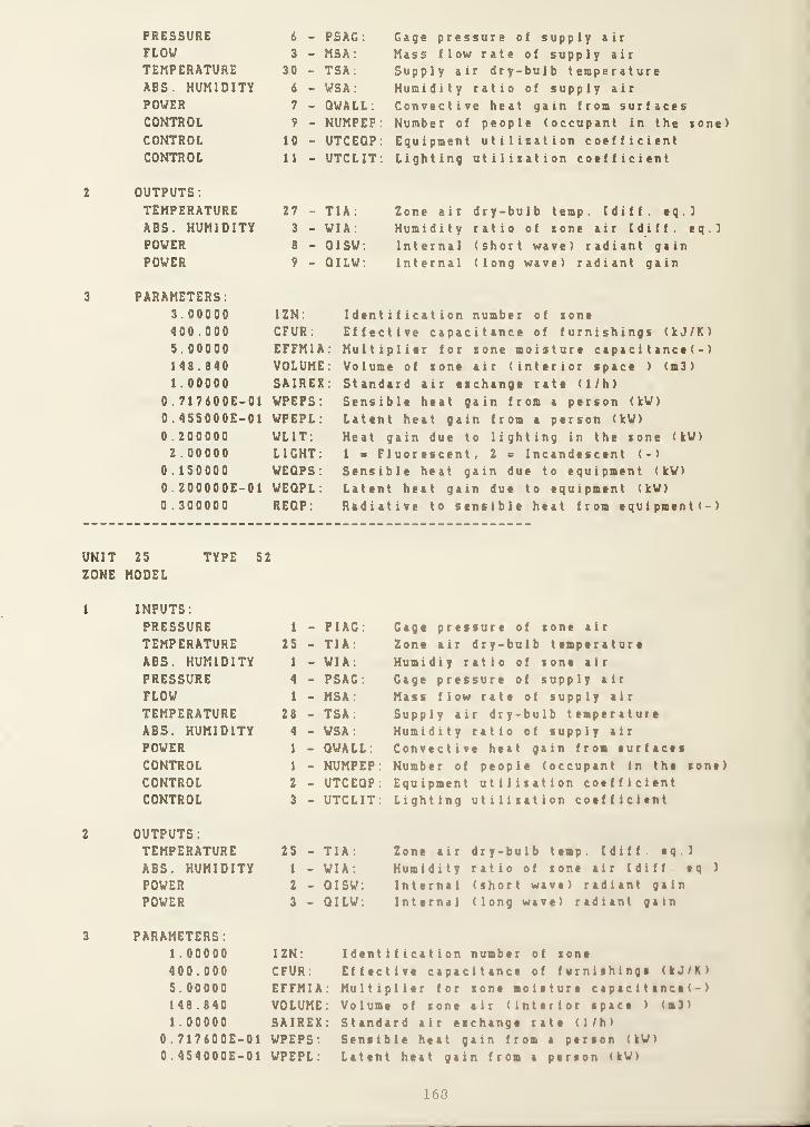
2
3
PRESSURE 6 - PSAG: Gage pressure of supply airFLOW 3 - MSA: Mass flow rate of supply airTEMPERATURE 30 - TSA; Supply air dry-bulb temperatureABS. HUMIDITY 6 - WSA: Humidity ratio of supply air
POWER 7 - QWALL: Convective heat gain from surfacesCONTROL 9 - NUMPEP : Number of people (occupant in the tone)
CONTROL 10 - UTCEQP: Equipment utilitation coefficientCONTROL 11 - UTCLIT; Lighting utilitation coefficient
OUTPUTS :
TEMPERATURE 27 - TIA: Zone air dry-bulb temp. Cdiff. eq.IABS. HUMIDITY 3 - WIA: Humidity ratio of tone air Cdiff. eq.]
POWER 6 - QISW: Internal (short wave) radiant gainPOWER 9 - QILW: Internal (long wave) radiant gain
PARAMETERS:3 . 00000 IZN;
400 . 000 CFUR:
5.00000 EFFMIA1 46 .640 VOLUME1 . 00000 SAIREX
0 . 717600E-01 WPEPS;0. 455000E-01 WPEPL:
0 . 200000 WLIT:2 . 00000 LIGHT:
0 .150000 WEQPS:0. ZOOOOOE-01 WEQPL:0 . 300000 REQP;
Identification number of toneEffective capacitance of furnishinge (kJ/K)
Multiplier for tone moisture capac i t ance ( -
)
Volume of tone air (interior space ) (m3)
Standard air eichange rate (1/h)
Sensible heat gain from a person (kV)
Latent heat gain from a person (kV)
Heat gain due to lighting in the tone (kV)
1 s Fluorescent, 2 = Incandescent (->
Sensible heat gain due to equipment (kV)
Latent heat gain due to equipment (kV)
Radiative to sensible heat from equipment(-)
UNIT 25 TYPE 52
ZONE MODEL
1
2
3
INPUTS;
PRESSURE 1 - PIAG: Cage pressure of tone air
TEMPERATURE 25 - TIA: Zone air dry-bulb temperatureABS. HUMIDITY 1 - WIA: Humidiy ratio of tone air
PRESSURE 4 - PSAG: Cage pressure of supply air
FLOW 1 - MSA: Mass flow rate of supply air
TEMPERATURE 26 - TSA; Supply air dry-bulb temperatureABS. HUMIDITY 4 - WSA: Humidity ratio of supply air
POWER 1 - QWALL: Convective heat gain from surfacesCONTROL 1 - NUMPEP: Number of people (occupant in the tone)
CONTROL 2 - UTCEQP: Equipment utilitation coefficientCONTROL 3 - UTCLIT; Lighting utilitation coefficient
OUTPUTS
:
TEMPERATURE 25 - TIA: Zone air dry-bulb temp. Cdiff. eq I
ABS. HUMIDITY 1 - WIA: Humidity ratio of tone air Cdiff eq I
POWER 2 - QISW: Internal (short wave) radiant gain
POWER 3 - QILW; Internal (long wave) radiant gain
PARAMETERS:1 . 00000 IZN;
400 .000 CFUR:
5. 00000 EFFMIA1 46 . 640 VOLUME1 . 00000 SAIREX
0.717600E-01 VPEPS:0.454000E-01 VPEPL:
Identification number of tone
Effective capacitance of furnishings (kJ/K)
Multiplier for tone moisture capac 1 1 ance (-
)
Volume of tone air (interior space ) (b 3)
Standard air eichange rate (1/h)
Sensible heat gain from a person (kV)
Latent heat gain from a person (kV)
160

0.200000 VLIT:
2.00000 LIGHTO.ISOOOO VEQPS0.200000E-01 VEQPL0.300000 REQP;
Heat gain due to lighting in the zone (kV)
1 = Fluorescent, 2 = Incandescent (-)
Sensible heat gain due to equipment (kV)
Latent heat gain due to equipment (kV)
Radiative to sensible heat from equipment(-)
UNIT 26 TYPE 52
ZONE MODEL
1
2
3
INPUTS:PRESSURE 2 - PIAG: Gage pressure of zone air
TEMPERATURE 26 - TIA: Zone air dry-bulb temperature
ABS. HUMIDITY 2 - VIA: Humidiy ratio of zone air
PRESSURE 5 - PSAG : Gage pressure of supply air
FLOV 2 - MSA: Mass flow rate of supply air
TEMPERATURE 29 - TSA: Supply air dry-bulb temperatureABS. HUMIDITY 5 - VSA : Humidity ratio of supply air
POVER 4 - QVALL
:
Convective heat gain from surfacesCONTROL 5 - NUMPEP: Number of people (occupant in the zone)
CONTROL 6 - UTCEQP: Equipment utilization coefficientCONTROL 7 - UTCLIT: Lighting utilization coefficient
OUTPUTS
:
TEMPERATURE 26 - TIA: Zone air dry-bulb temp. Cdiff. eq.l
ABS. HUMIDITY 2 - VIA: Humidity ratio of zone air Cdiff. eq.l
POVER 5 - QISV: Internal (short wave) radiant gainPOVER 6 - QILV: Internal (long wave) radiant gain
PARAMETERS:2.00000 IZN:
400.000 CFUR:
5. 00000 EFFMIA148.840 VOLUME1.00000 SAIREX
0.717600E-01 WPEPS:0. 454000E-01 VPEPL:0.200000 VLIT:2.00000 LIGHT:
0.150000 VEQPS:0.200000E-01 VEQPL:0.300000 REQP.
Identification number of zone
Effective capacitance of furnishings (kJ/K)
Multiplier for zone moisture capac i t ance ( -
)
Volume of zone air (interior space ) (m3)
Standard air ezchange rate (1/h)
Sensible heat gain from a person (kV)
Latent heat gain from a person (kV)
Heat gain due to lighting in the zone (kV)
1 = Fluorescent, 2 s Incandescent (-)
Sensible heat gain due to equipment (kV)
Latent heat gain due to equipment (kV>
Radiative to sensible heat from equipment(-)
UNIT 27 TYPE 3
INLET CONDUIT (DUCT OR PIPE)
1
.2
INPUTS:
PRESSURE 7 -
PRESSURE 8 -
TEMPERATURE 31 -
TEMPERATURE 32 -
TEMPERATURE 33 -
OUTPUTS:TEMPERATURE 33 -
FLOV 3 -
INLET FLUID PRESSUREOUTLET FLUID PRESSUREINLET FLUID TEMPERATUREAMBIENT AIR TEMPERATUREOUTLET FLUID TEMPERATURE
OUTLET FLUID TEMPERATUREFLUID MASS FLOV RATE
(SAME AS FIRST OUTPUT)
(SAME AS FIFTH INPUT)
3 ' PARAMETERS:0.000000 INSIDE HEAT TRANSFER COEFFICIENT I AREA (KV/C)
169

0 .0000000 . 0000000 . 0000000. 1 250000 . 000000
1 . 00000
OUTSIDE HEAT TRANSFER COEFFICIENT X AREA (KW/C)THERMAL CAPACITANCE OF CONDUIT MATERIAL (KJ/C)VOLUME <M3)
FLOW RESISTANCE [0.001/(KG M)]
HEIGHT OF OUTLET ABOVE INLET (M)
MODE: 2=WATER, UAIR, NEG . =DETA I LED , POS.»SIMPLE DYNAMI
UNIT 28 TYPE 1
FAN OR PUMP
1 INPUTS:
FLOW 3
PRESSURE 9
RVPS 1
TEMPERATURE 33
2 OUTPUTS
:
PRESSURE e
TEMPERATURE 30
POWER 10
- MASS FLOW RATE OF FLUID- OUTLET PRESSURE- FAN OR PUMP ROTATIONAL SPEED- INLET FLUID TEMPERATURE
- INLET PRESSURE- OUTLET FLUID TEMPERATURE- POWER CONSUMPTION
3 PARAMETERS:3 .64000
0 .80 1000-0 . 190000
444000E000000000000564000
-0 . 862000E0 .0000000.0000000.336500
1 .00000
1ST PRESSURE COEFFIC2ND PRESSURE COEFFIC3RD PRESSURE COEFFIC
-02 4TH PRESSURE COEFFIC5TH PRESSURE COEFFIC1ST EFFICIENCY COEFF2ND EFFICIENCY COEFF
-01 3RD EFFICIENCY COEFF4TH EFFICIENCY COEFF5TH EFFICIENCY COEFFDIAMETER (M)
MODE: AIRbI, WATER=2
I ENTI ENTI ENTI ENTI ENTICIENTI C I ENTICIENTICIENTICIENT
UNIT 29 TYPE 2
CONDUIT (DUCT OR PIPE)
1 INPUTS:
FLOW 3
PRESSURE 6
TEMPERATURE 30
TEMPERATURE 32
TEMPERATURE 30
FLUID MASS FLOW RATE
OUTLET PRESSUREFLUID INLET TEMPERATUREAMBIENT TEMPERATUREOUTLET FLUID TEMPERATURE (SAME AS FIRST OUTPUT)
2 OUTPUTS
:
TEMPERATUREPRESSURE
OUTLET FLUID TEMPERATURE (SAME AS FIFTH INPUT)
INLET PRESSURE
3 PARAMETERS:0.000000 INSIDE HEAT TRANSFER COEFFICIENT I AREA (KW/C)
0.000000 OUTSIDE HEAT TRANSFER COEFFICIENT I AREA (KW/C)
0.000000 THERMAL CAPACITANCE OF CONDUIT MATERIAL (KJ/C)
0.000000 VOLUME (M3)
0.125000 FLOW RESISTANCE [ 0 . 00 1 / (KG M)
1
0.000000 HEIGHT OF OUTLET ABOVE INLET (M)
1.00000 MODE; 2-WATER, 1-AIR, NEG . -DETA I LED , P08. -SIMPLE DYNAMI
170

UNIT 30 TYPE 2
CONDUIT (DUCT OR PIPE)
1 INPUTS:FLOW 3
PRESSURE 10
TEMPERATURE 27
TEMPERATURE 32
TEMPERATURE 27
FLUID MASS FLOW RATE
OUTLET PRESSUREFLUID INLET TEMPERATUREAMBIENT TEMPERATUREOUTLET FLUID TEMPERATURE (SAME AS FIRST OUTPUT)
2 OUTPUTS:TEMPERATURE 0 - OUTLET FLUID TEMPERATURE (SAME AS FIFTH INPUT)
PRESSURE 3 - INLET PRESSURE
PARAMETERS;0.000000 INSIDE HEAT TRANSFER COEFFICIENT X AREA (KV/C)
0.000000 OUTSIDE HEAT TRANSFER COEFFICIENT X AREA (KV/C)
0.000000 THERMAL CAPACITANCE OF CONDUIT MATERIAL (KJ/C)
0.000000 VOLUME (M3)
0.125000 FLOV RESISTANCE 1 0 . 00 1 / (KG M)
]
0.000000 HEIGHT OF OUTLET ABOVE INLET (M)
1 . 00000 MODE: 2=VATER, UAIR
Initial Vari able Valu es :
PRESSURE 1 -) 0 .
0
00000 (kPa)
PRESSURE 2 -> 0 . 0 00000 (k^)PRESSURE 3 -> 0.3 00000 (kPa)
PRESSURE 4 -> 0 . 0 00000 (kPa)
PRESSURE 5 -) 0.000000 (kPa)
PRESSURE 6 -> 0.5 00000 (kPa)
PRESSURE 7 -> 0 .
0
00000 (kPa)
PRESSURE 8 -> -0 .
8
00000 (kPa)
PRESSURE 9 -) 1 . 00000 (kPa)
PRESSURE 10 -> -0 . 500000 (kPa)
PRESSURE 11 -> 0 .
0
00000 (kPa)
FLOW 1 -> 0.0 00000 (kg/s)FLOW 2 -> 0 . 0 00000 (kg/s )
FLOW 3 -> 2 . 49683 (kg/s)TEMPERATURE 1 20 .0000 (C)
TEMPERATURE 2 -> 20 .0000 (C)
TEMPERATURE 3 -> 20 . 0000 (C)
TEMPERATURE 4 -> 20 . 0000 (C)
TEMPERATURE 5 -> 20 . 0000 (C)
TEMPERATURE 6 -> 20 .0000 (C)
TEMPERATURE 7 -> 20 . 0000 (C)
TEMPERATURE 8 -> 20 . 0000 (C)
TEMPERATURE 9 -> 20 .0000 (C)
TEMPERATURE 10 -> 20 .0000 (C)
TEMPERATURE 11 -> 20 . 0000 (C)
TEMPERATURE 12 -> 20 . 0000 (C)
TEMPERATURE 13 -> 20 . 0000 (C)
TEMPERATURE 14 -> 20 . 0000 (C)
TEMPERATURE IS -) 20 . 0000 (C)
TEMPERATURE 16 -) 20 . 0000 (C)
TEMPERATURE 17 -> 20 . 0000 (C)
TEMPERATURE 18 -> 20 .0000 (C)
TEMPERATURE 19 -> 20 . 0000 (C)
TEMPERATURE 20 -> 20 .0000 (C)
171

TEMPERATURE 21 -> 15 . 0000 (C)
TEMPERATURE 22 -> 20 . 0000 (C)
TEMPERATURE 23 -> 20 . 0000 (C)
TEMPERATURE 24 -> 20 .0000 (C)
TEMPERATURE 25 -> 20 . 0000 (C)
TEMPERATURE 2i -> 20 .0000 (C)
TEMPERATURE 27 -> 20 . 0000 (C)
TEMPERATURE 28 -> 20 . 0000 (C)
TEMPERATURE 29 -> 20 . 0000 (C)
TEMPERATURE 30 -> 20 . 0000 (C)
TEMPERATURE 31 -> 20 . 0000 (C)
TEMPERATURE 32 -> 20 .0000 (C)
TEMPERATURE 33 -> 20 . 0000 (C)
CONTROL 1 -> 1 .00000 (-)
CONTROL 2 -> 1 . 00000 (-
)
CONTROL 3 -> 1 . 00000 (-)
CONTROL 4 -> 0 . 000000 (-
)
CONTROL 5 -> 1 . 00000 (-)
CONTROL 6 -> 1.00000 (-)
CONTROL -7 -> 1 . 00000 (-)
CONTROL 8 -> 0 .000000 (-)
CONTROL 9 -> 1 . 00000 (-)
CONTROL 10 -> 1.00000 (-)
CONTROL 11 -> 1 . 00000 (-)
CONTROL 12 -> 0 . 000000 (-
)
RVPS 1 -> 60 . 0000 ( r ev / 5 )
POWER 1 -> 0 .000000 (kW)
POWER 2 -> 0 . 000000 (kW)
POWER 3 -> 0.000000 (kW)
POWER 4 -> 0 . 000000 (kW)
POWER 5 -> 0.000000 (kW)
POWER 6 -> 0.000000 (kW)
POWER 7 -> 0 .000000 (kW)
POWER 8 -> 0 . 000000 (kW)
POWER 9 -> 0.000000 (kW)
POWER 10 -> 0.000000 (kW)
POWER 11 -> 0.000000 (kW)
POWER 12 -> 0 . 000000 (kW)
POWER 13 -> 0.000000 (kW)
ABS. HUMIDITY 1 -> 0.740000E- 03(kg(water)/kg(air)>ABS. HUMIDITY 2 -> 0 . 740000E- 03(kg(water) /kg(air)
)
ABS. HUMIDITY 3 -> 0 . 740000E- 03(kg(water)/kg(air)>
ABS. HUMIDITY 4 -> 0 . 740000E- 03(kg(water)/kg(air)
)
ABS. HUMIDITY 5 -> 0.740000E- 03<kg(water)/kg(air)
)
ABS. HUMIDITY 6 -> 0 . 740000E- 03(kg(water)/kg(air)
)
ABS. HUMIDITY 7 -> 0 .000000 (kg(water)/kg(air)>
Siaulation Error Tolerances:
1 RTOLX>XTOL =
0 . 500000E-020.500000E-03
ATOLX-TTIME-
SCAN OPTION 0
SCAN OPTION 0
0 . lOOOOOE-OS10.0000
SUPERBLOCK 1
2 FREEZE OPTION 0
SUPERBLOCK 2
3 FREEZE OPTION 0
The following are Boundary Variables in the siaulation:
172

TEMPERATURE 31
The following ire the reported virii
SUPERBLOCK 1 REPORTING INTERVAL
TEMPERATURE 1
TEMPERATURE 2
TEMPERATURE 3
TEMPERATURE 4
TEMPERATURE 5
TEMPERATURE 6
TEMPERATURE 7
TEMPERATURE 8
TEMPERATURE 14
TEMPERATURE 32
POWER 1
POWER 4
POWER 7
POWER 11
POWER 12
POWER 13
SUPERBLOCK 2 REPORTING INTERVALTEMPERATURE 25
TEMPERATURE 26
TEMPERATURE 27
TEMPERATURE 30
TEMPERATURE 31
ABS. HUMIDITY 1
ABS. HUMIDITY 2
ABS. HUMIDITY 3
Selection ?
END
STOP
173

(2) Creation of Model Definition File
* Esecution of SLIMCON
Simulation Work File to Model Definition File ConverterVersion 2.1 (November 13, 1984)
Enter the simulation filename (Up to 8 characters) or carriage returnTHRIZONE
2 superblocks in the simulation MAXIMUM a 10
8 blocks in the simulation MAXIMUM = 50
6 differential equations in the simulation MAXIMUM = SO
1173 saved variables in the simulation MAXIMUM =600031 units in the simulation MAXIMUM = 200
8 units in a single block MAXIMUM = 20
2 differential equations in one unit MAXIMUM = 10
13 inputs or outputs in a single unit MAXIMUM = 20
14 parameters in a single unit MAXIMUM = 30
4 blocks in the largest superblock MAXIMUM = 10
6 differential equations in one superblock MAXIMUM = 20
80 state variables in the simulation MAXIMUM = 600
14 inputs or outputs in a single block ... MAXIMUM = SO
361 unit parameters in the simulation MAXIMUM =1000
8 simultaneous equations in a single block MAXIMUM = 30
1 simultaneous equations in one superblock MAXIMUM = 20
1 time dependent boundary variables MAXIMUM « 30
1 boundary conditions in one superblock . MAXIMUM = 20
16 reported variables in one superblock ... MAXIMUM = 30
0 end .
20 . 0 %)
16.0%)
12 . 0 %)
19 6%)
15 S%)
40 . 0%)
20 . 0 %)
65 . 0%)
46 . 7%)
40 0%)
30 0%)
13 3%)
2 8 0 %)
36 1%)
26 . 7%)
5 0%)
3 3%)
5 0%)
5 3 3%)
174
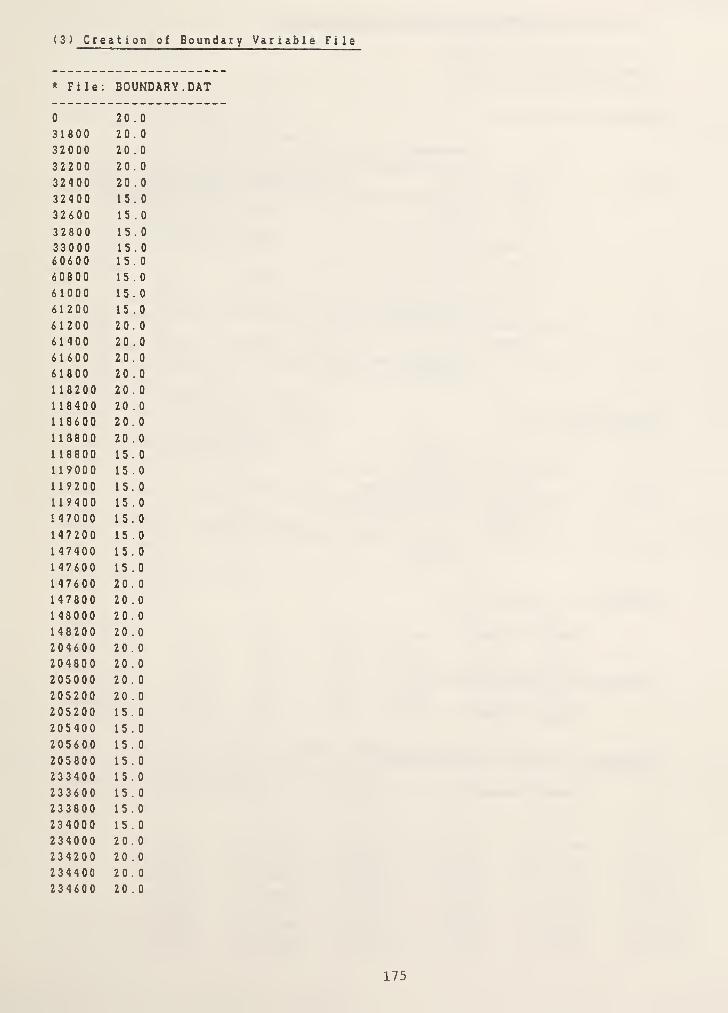
( 3 ) Creation of Boundar y Variable File
* File: BOUNDARY.DAT
0 20 . 0
31800 20 . 0
32000 20 . 0
32200 20 . 0
32400 20 . 0
32400 15.0
32600 15.0
32800 15.0
33000 15.060600 15.0
60800 15.0
6 1000 15.0
61200 15.0
6 1200 20 . 0
61400 20 . 0
61600 20 . 0
61800 20 . 0
118200 20 . 0
118400 20 . 0
118600 20.0
118800 20 . 0
118800 15.0
119000 15.0
119200 15.0119400 15.0
147000 15.0
147200 15.0
147400 15.0
147600 15.0
147600 20.0147800 20.0148000 20 . 0
148200 20 . 0
204600 20.0204800 20 . 0
205000 20 . 0
205200 20 . 0
205200 15.0
205400 15.0
205600 15.0
205800 15.0
233400 15.0
233600 15.0
233800 15.0
234000 15.0
234000 20 . 0
234200 20 . 0
234400 20.0234600 20.0
175

(4) Creation of Conduction Transfer Function File
* Composition of constructs
CONSTRUCT #1 (Ceiling)
(Outside)
Layer 1 Slag, 1/2-in. (44)
2 Felt, 3/8-in. (45)
3 Concrete, 4-in. (36)
4 Insulat ion, 4-in
.
( 20 )
5 Ceiling air space ( 46 )
6 Acoustic tile ( 47 )
(Inside)
CONSTRUCT #2 (Floor)
(Outside)
Layer 1 Concrete , 1 .w. , 4-in
.
(36)
2 Vinyle tile, 3.32-in. (48)
(Inside)
[mater i a 1 I . D . D
in THERM.DAT file]
CONSTRUCT «3 (Interior Vails)
Same as Example 1
CONSTRUCT «4 (Exposed Wall)
Same as Example 1
CONSTRUCT «5 (Exposed Glass Window)
Same as Example 1
176

* Enecution of CTFGEN
Enter your choice;tt*************************************************
A => Add thermal property data to the constructionmaterials database (THERM.DAT)
B => Print the contents of the data file THERM.DATto Logical Unit i
C => Create a CTF data file
D => Change time interval in an existing CTF data file
E => END
C
Enter the name of the CTF Definition File,or carriage return for default name; CTF1NFUT.DAT
Enter the name of the CTF Output File,
or carriage return for default name; CTFDATA.DAT
What kind of output do you want?0 s=> for a very simple output,1 ==> for a less simple output,2 ==> for detailed output or
3 s=> for root search1
Vhat is the time interval for CTF calculation in s ?
900
THIS CONSTRUCT ID NUMBER (ISTR) IS 1
How many layers in this construct? (max. s 10 )
6
Enter the layer ID numbers with most outer layer first44,45,36,20, 46 ,47
LAYER L K CP D R RC
Slag or St 0.013 1 .436 0 . 465 881.000 0.009 6 .783
Felt & mem 0.010 0 .190 0 . 465 1121.000 0.050 15.735Concrete , 0.102 0.173 0 .233 640.000 0.586 94.328Insulat ion 0.102 0 .043 0 .233 91.000 2.346 71.344Ceiling ai 0.000 0 .000 0 .000 0.000 0.176 0.000
Acous t i
c
t 0.016 0.061 0 .233 480.000 0.315 21.529
SUMRC = 209.71966 CND = 0.29023 TINC = 900.00
NUMBER OF RESPONSE FACTORS = 6; ORDER = 3
N 0 0 0 1 0 2 0 3 0 4 0 5
0 1 4 . 557249 14.557249 14.557249 14.557249 14.557249 1 4 . 5572491 -1 1 .701724 -23 .404494 -28.110588 -30.256600 -30.524282 -30 .636 33 8
2 -0 . 807326 8 . 599849 16.166097 20.310126 20.866491 21 . 1014543 -0.404115 0 .244905 -2.535270 -4.918456 -5.291923 -5.4525454 -0.279811 0.045063 -0.034110 0.339636 0.430078 0 . 4708135 -0 .2 14535 0 .010408 -0.004160 0.000869 -0 .005377 -0.0086876 -0.169705 0 . 002763 -0.000602 0.000012 0 . 000000 0 . 000000
177

0 0 .000001 0 .000001 0 .000001 0 .000001 0 .00000 1 0.0000011 0 . 001435 0 . 001434 0 . 001433 0 . 001433 0 . 001433 0 . 0014332 0.015018 0 .0 1 3864 0 .013401 0.013190 0.013163 0.0131523 0 . 033322 0 . 021249 0 .016767 0 . 014791 0 .014549 0 . 0 1 44474 0.039358 0 .012570 0 .005701 0 .003229 0 .002957 0.0026455 0 . 036730 0 . 005089 0 . 001025 0 . 000185 0 . 000126 0 . 0001036 0 .031329 0.001801 0 .000156 0 . 000005 0 .000000 0 .000000
0 2 . 4562 1 6 2 . 456216 2 . 456216 2 . 456216 2 . 456216 2 . 45 62 1 6
1 -1 .908972 -3.883557 -4.677607 5 .039699 -5 .084865 -5.1037722 -0 .143329 1 . 391319 2 .646803 3 . 336370 3 . 429041 3 .468 1 82
3 -0 .047651 0 .067573 -0.382215 0 .772404 -0 .833754 -0.8601494 -0 . 020781 0 .017526 -0 . 004319 0 . 052027 0 . 066230 0 .07 2 6 4 8
5 -0.011357 0 .005349 -0 .0003 17 0 .000320 -0 .000637 -00011476 -0 . 007443 0 . 001688 -0 . 000042 0 .000005 0 . 000000 0 . 000000
3 1 . 274614 -0 .426060 0.038313 0 .000000 0 . 000000
ISTR. 1
NCTF: 6 NORD; 3
UVAL : 0 .290227
CTFX : 14.5573, -30 2568, 20.3102, -4.91848, 0 . 339638 , 8 . 68591E- 04,
1 . 171E - 05
CTFY ; 1 . 18807E-06
,
1 . 43323E-03 , 1 . 31896E-02 , 1 . 47913E- 02, 3.22913E-03,1.8491E-04. 5.01Z3E-06CTFZ: 2.45622, -5.03971, 3.33638, -0.772406, 5.2027E-02, 3.19892E-04,4 . 97476E-06CTFQ; 1.27461, -0.42606, 3.83128E-02Do you want to continue? <N>
Y
THIS CONSTRUCT ID NUMBER (ISTR) IS 2
How many layers in this construct? (mas. & 10 )
2
Enter the layer ID numbers with most outer layer first
36,48
LAYER L K CP D R RC
Concrete , 0.102 0.173 0.233 640 .000 0.586 94.328Viny 1
e
til 0.002 0 .270 1 . 004 1552 .000 0.000 4 80S
SUMRC = 99.13220 CND = 1 .681 55 TINC = 900 .00
NUMBER OF RESPONSE FACTORS = 3; ORDER r 2
N 0 0 0 1 0 2 0 3 0 4 0 5
0 6 .04 1 242 6 . 04 1 242 6 .04 1 242 6 . 04 1 2 42 6.041242 6 041242
1 -3 .530460 -5.812812 -5 .936175 -5 . 9 3 7 1 36 -5 . 9 37 1 3 7 -5 937137
2 -0 . 5221 49 0.811642 0 . 930340 0 . 931285 0931286 0 931286
3 -0 .191197 0 . 006068 -0 .010506 0 .000000 0 .000000 0 000000
0 0 . 1 22326 0 . 122326 0 . 122326 0.122326 0 . 1 2 2 3 2 6 0 122326
1 0 .755747 0 . 709533 0 .707035 0 . 707016 0 . 7 0 70 1 6 0 707016
2 0 . 493480 0 . 207962 0 . 193473 0.193361 0 . 1 9 3 3 6 0 0 193360
3 0 . 1 92747 0 .0063 1 3 0 .002066 0.000000 0000000 0 000000
0 9 .21 8291 9 .218291 9.218291 9.218291 9218291 9 218291
1 -6 .686454 -10.169080 -10 .357318 -10.358785 -10 358787 -10 358787
2 -0 .535869 1 .99024 1 2 . 1 97894 2.199543 2 199544 2 199544
3 -0 .1 95773 0.006676 -0 .033965 0.000000 0000000 0 000000
170

2 0.398215 -0.007715 0.000000 0.000000 0.000000
ISTR; 2
NCTF; 3 NORD ; 2
UVAL; 1.68155
CTFX: 6.04124, -5.93617, 0.93034, -1.05061E-02
CTFY: 0.122326, 0.707036, 0.193473, 2.06644E-03
CTFZ: 9.21829, -10.3573, 2.19789, -3.39653E-02
CTFQ; 0.398215, -7.71461E-03Do you want to continue? <N>
Y
THIS CONSTRUCT ID NUMBER (ISTR) IS 3
How many layers in this construct? (maK . = 10 )
Enter the
43,8,43
layer ID numbers with most outer layer first
LAYER L K CP D R RC
Plaster/ gy 0.019 0 . 727 0 .233 1 60 1 .000 0 .026 13.610
Air Space 0 .000 0 . 000 0 . 000 0 . 000 0.160 0 . 000
Plaster/gy 0.019 0 .727 0 .233 1 60 1 .000 0.026 13.610
SUMRC = 27 . 220 12 CND = 4.71099 TINC = 900 . 00
NUMBER OF RESPONSE FACTORS = 1 ; ORDER = 1
N 0 0 0 1 0 2 0 3 0 4 0 5
0 11.696103 11 .696103 1 1 .6961 03 0 .000000 0 .000000 0 .0 00 000
1 -6. 985093 -6 . 985166 0 .000000 0 . 000000 0 .000000 0 . 000000
0 3 .820999 3 . 820999 3 . 820999 0 .000000 0 .000000 0 . 0000001 0 . 889971 0 .889947 0 .000000 0 . 000000 0 .000000 0 . 000000
0 11 .696103 11.696103 11.696103 0 .000000 0 .000000 0.0000001 -6 .985093 -6 .985166 0 .000000 0 . 000000 0 . 000000 0 .000000
1 0 .000006 0 . 000000 0 .000000 0 .000000 0 .0 00 0 0 0
ISTR 3
NCTF 1 NORD: 1
UVAL 4 . 71099CTFX 1
1
.6962, -6 .985 2
CTFY 3 . 82101, 0. 88995
CTFZ 1
1
.6962, -6 .985 2
CTFQ 6 . 21576E-06Do you want to continue? <N>
THIS CONSTRUCT ID NUMBER (ISTR) IS 4
How many layers in this construct? (max. = 10 )
Enter the
2,10,8,43layer ID numbers with most outer layer first
LAYER L K CP D R RC
Facebr i ck 0.102 1 .298 0.256 2082.000 0.078 65.105
Insu
1
a t ion 0.051 0 . 043 0.233 32 . 000 1.176 21.154Ai r Space 0.000 0.000 0.000 0.000 0.160 0.000
Plaster/gy 0.019 0.727 0 .233 1 60 1 . 000 0.026 13.610
SUMRC = 99.86891 CND = 0.69166 TINC = 900.00
179
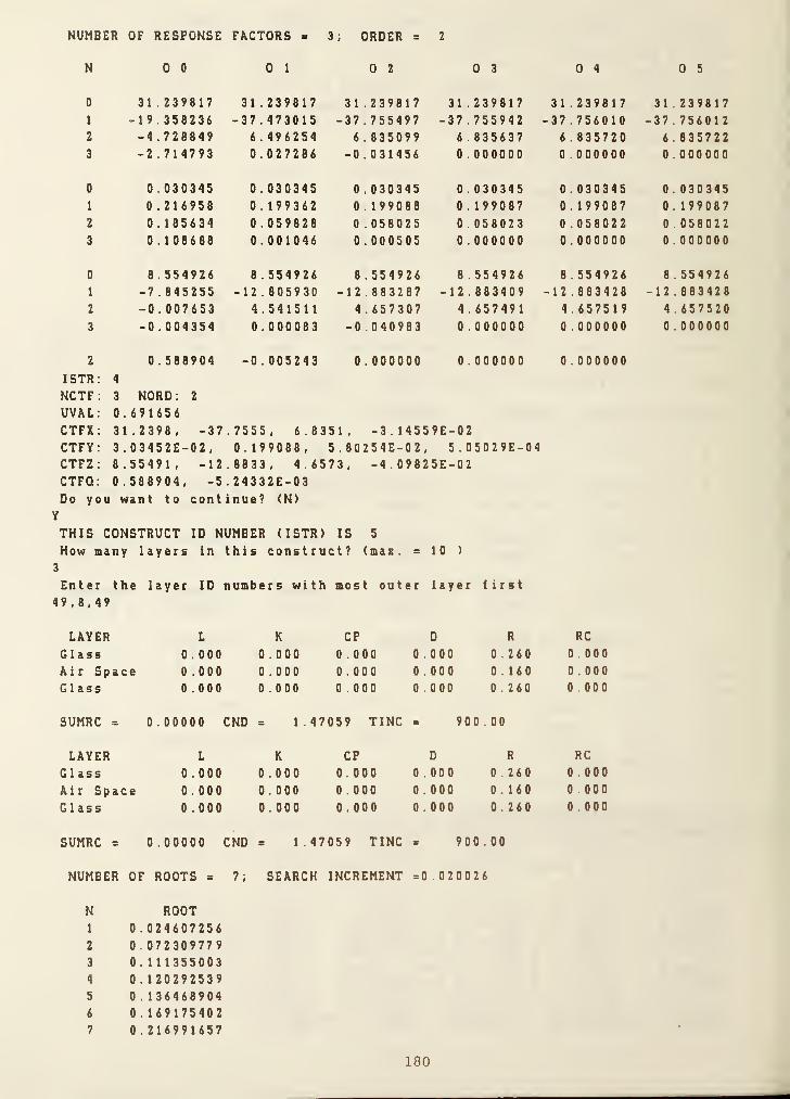
NUMBER OF RESPONSE FACTORS = 3; ORDER = 2
N 0 0 0 1 0 2 0 3 0 4 0 5
0 31 .239817 31 . 239817 31 .2398 1 7 31 .239817 31 .2398 1 7 3 1 . 2398 1 7
1 -19.358236 -37.473015 -37.755497 - 37.755942 -37 .7560 1 0 -37.7560122 -4 . 728849 6 . 496254 6 . 835099 6 .835637 6 . 835720 6 . 8357223 -2 .714793 0 .027286 -0 .03 1 456 0 .000000 0 .000000 0 . 000000
0 0 . 030345 0 . 030345 0 .030345 0 . 030345 0 . 030345 0 . 0303451 0 .216958 0 . 1 99362 0 .1 99088 0 . 199087 0 . 1 99087 0 . 1 9908 7
2 0 .185634 0 . 059828 0.058025 0 . 058023 0 . 058022 0 . 05 802 2
3 0 .108688 0 .001046 0 .000505 0 . 000000 0.000000 0 . 000000
0 8 . 554926 8 . 554926 8 . 554926 8 . 554926 8 . 554926 85549261 -7 .845255 -12.805930 -12.883287 - 12.883409 -12 . 883428 - 1 2 . 883 42 8
2 -0 . 007653 4.541511 4 . 657307 4 . 657491 4 .6575 1 9 4 . 657520
3 -0 .004354 0 .000083 -0 .040983 0 .000000 0 .000000 0 . 000000
2 0 .588904 -0 . 005243 0 . 000000 0 . 000000 0 .000000
ISTR 4
NCTF 3 NORD; 2
UVAL 0.691656CTFX 31.2398, -37 7555, 6.8351, -3.14559E -02CTFY 3 . 03452E-02 , 0. 199088, 5 . 80254E-02 , 5 . 05029E-04CTFZ 8.55491, -12 8833, 4.6573, -4.09825E -02CTFQ. 0.588904, -5 24332E-03Do you want to continue? <N>
Y
THIS CONSTRUCT ID NUMBER (ISTR) IS 5
How many layers in this construct? (mas. = 10 )
3
Enter the layer ID numbers with most outer layer first
49,8,49
LAYER L K CP D R RC
Glass 0 .000 0.000 0.000 0.000 0.260 0 0 00
Air Space 0.000 0.000 0.000 0.000 0.160 0.000
Glass 0 .000 0.000 0.000 0.000 0.260 0.000
SUMRC = 0.00000 CND = 1.47059 TINC = 900.00
LAYER L K CP D R RC
Glass 0.000 0.000 0.000 0.000 0.260 0.000
Air Space 0.000 0.000 0.000 0.000 0.160 0 00 0
Glass 0 .000 0.000 0.000 0.000 0.260 0 . 000
SUMRC = 0.00000 CND = 1.47059 TINC * 900.00
NUMBER OF ROOTS = 7; SEARCH INCREMENT =0.020026
N ROOT1 0 . 0246072562 0 . 0723097793 0. 1113550034 0 . 1202925395 0 . 1364689046 0 . 1691754027 0 .216991657
180
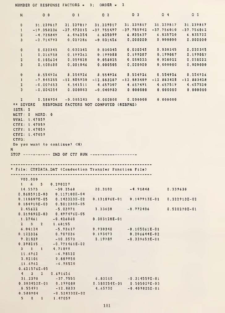
NUMBER OF RESPONSE FACTORS = 3; ORDER = 2
N 0 0 0 1 0 2 0 3 0 4 0 5
0 3 1 .2398 17 31 .2398 1 7 31.239817 31.239817 31.239817 3 1 .2398 1 7
1 -19.358236 -37.473015 - 37 . 755497 -37 . 755942 -37 . 7560 1 0 -37.756012
2 -4 .728849 6 .49625 4 6 .835099 6.835637 6.835720 6.835722
3 -2 .7 1 4793 0 .027286 -0 .031456 0 . 000000 0 .000000 0 . 000000
0 0 .030345 0 .030345 0 .030345 0.030345 0.030345 0 .0 3 0 3 4 5
1 0 .2 1 6958 0 . 199362 0 . 199088 0 . 199087 0.199087 0.199087
2 0 . 185634 0 . 059828 0 .058025 0 . 058023 0.058022 0 .058022
3 0 . 1 08688 0 . 001046 0 . 000505 0 . 000000 0 .000000 0.000000
0 8 .554926 8 .554926 8 .554926 8.554926 8 .5 5 4 9 2 6 8.5549261 -7.845255 -12.805930 - 12 . 883287 -12 . 883409 -1 2 . 883428 - 1 2 . 883428
2 -0 .007653 4.541511 4 .657307 4 . 657491 4.657519 4.6575203 -0.004354 0 .000083 -0 .040983 0 . 000000 0.000000 0.000000
2 0 .588904 -0 .005243 0 .000000 0.000000 0 . 000000** SEVERE RESPONSE FACTORS NOT COMPUTED (RESPNS)ISTR; 5
NCTF: 0 NORD. 0
UVAL; 1.47059
CTFX; 1.47059CTFY: 1.47059CTFZ; 1.47059CTFQ:
Do you want to continue? <N>
N
STOP END OF CTF RUN
File; CTFDATA
.
DAT (Conduction Transfer Function File)
900.0001 6 3 0 . 29022 7
14.5573 -30 . 2568 20.3102 -4.91848 0.3396380 . 868591E-03 0 . 117100E-040 . 1 1 8807E-05 0 . 143323E-02 0 . 131896E-01 0 . 147913E-01 0 . 322913E-020 . 1 849 1 0E-03 0 . 501230E-052 . 45622 -5 .0397 1 3 .33638 -0 . 772406 0 . 520270E-01
0 . 319892E-03 0 . 497476E-051 .2746 1 -0 .426060 0 . 383128E-012 3 2 1.681556.04124 -5 .936 1 7 0 .930340 -0 . 105061E-01
0 . 1 22326 0 . 707036 0 . 193473 0 . 206644E-029.21829 -10 .3573 2 . 1 9789 -0 . 339653E-01
0 .3982 15 -0 . 771461E-023 1 1 4.710991 1 . 6962 -6 .98520
3.82101 0 . 88995011.6962 -6.98520
0 . 621576E-054 3 2 0.69165631.2398 -37.7555 6.83510 -0 . 3 1 4559E-0
1
0 . 303452E-01 0 . 1 99088 0 . 5802S4E-01 0 . 505029E-038 . 5549 1 -12.8833 4 .65730 -0 . 409825E-0 1
0.588904 -0 . 524332E-025 0 1 1 . 47059
181

1 .470591 . 47059I .47059
0 . 000000
* File; CTFINPUT.DAT (CTF Input Data File)
900 . 000
6 44 45 36 20
2 36 48
3 43 8 43
4 2 10 8 43
3 49 8 49
182

(5) Creation of Weather Data File
* Eaecution of RDTAPC
Enter Input File name up to 12 charactersWYEC67.DAT
What is the type of weather tape?
Enter 1 for (TRY), 2 (TMY), 3 (SOLMET), 4 (WYEC)
4
Where is the weather station?Enter station ID number
93734
Enter the year (4 digits)1961
Type the start date: Month, Day7,7
Type the stop date: Month, Day
7,9
The first day of the weather tape
STTN=93734 WYR=1960 WM0=6 WDY=2The start day
STTN=93734 WYR=1961 WM0=7 WDY=7The stop day
STTN=93734 WYRxl961 WM0=7 WDY=93 DAYS WRITTEN ON THE OUTPUT FILE
STOP NORMAL END OF JOB
* File: WYEC67.DAT
(From July 7 to July 9)
93734068066065180005300300202302800077702000777020007779999937340680660652300033001000003030000777000007770000077799999373406706606500000029990000020140007770000077700000777999993734067066065000000299800808302500077708000777080007779999937340670660650000002997004012018033030040088880400077799999373406706606507000429981101030359999999999999999999999000093734067066065050004299810805303803888808000777080007770008937340690680670500043000110005020103030109999999999999900689373407206906700000030000090340120030300306888809000777017493734074069066110004299900906402503888809000777090007770355937340730690671400062999010034018103032109999999999999904299373407607106807000529980100440321030551099999999999999052493734076070067160005299701007402703305510999999999999990545937340780710672000062995007073032000777070007770700077707819373408007206816000829930050530400088880500077705000777029893734081073069160006299100604404002888806000777060007770510937340800710671800072990008044040048888080007770800077704679373408007106716000629880080340400598880800077708000777036993734079071067180008298700902403507988809000777090007770209937340770700671800062987009024035079888090007770900077700439373407407006816000629870070240300598880700077707000777000093734073070068160006298700800503002403502069888080007779999
19610707009196107070191961070702919610707039196107070491961070705019610707060196107070701961070708019610707090196107071001961070711019610707120196107071301961070714019610707150196107071601961070717019610707180196107071901961070720019610707219
183
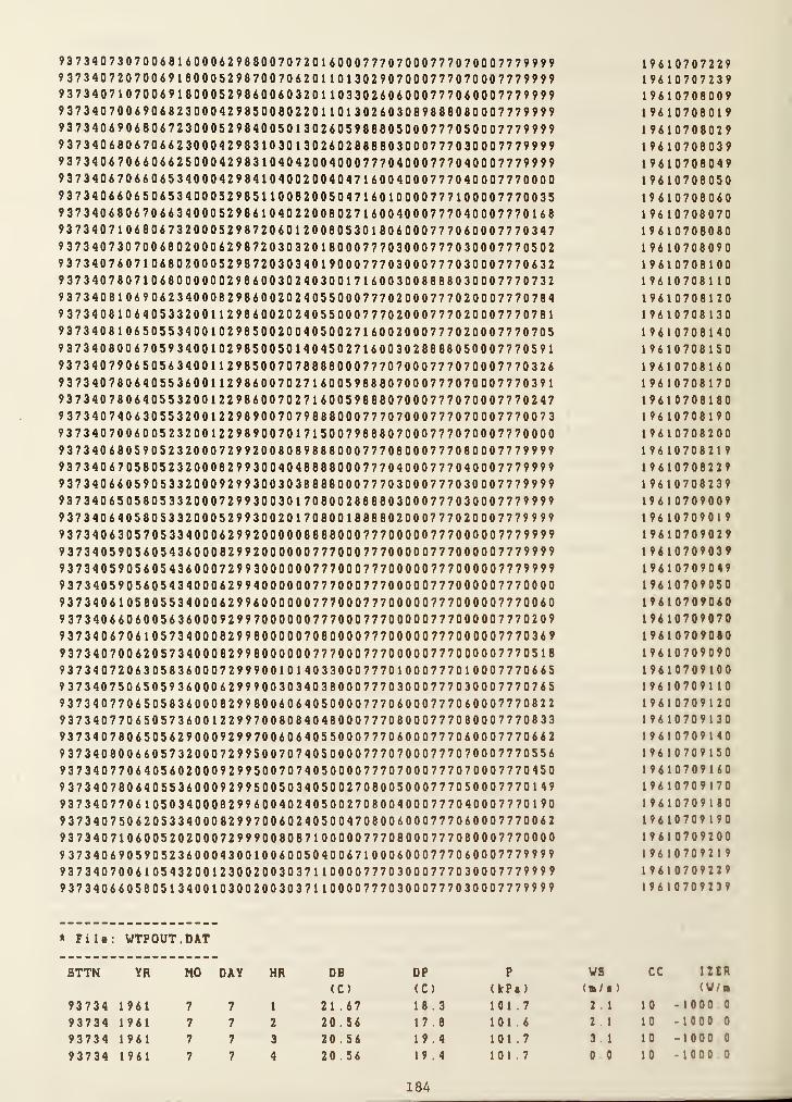
93 734073070068 1 6000629880070720 I 60007770700077707000777?99993734072070069180005298700706201101302907000777070007779999937340710700691800052986006032011033026060007770600077799999373407006906823000429850080220110130260308988808000777999993734069068067230005298400501302605988805000777050007779999937340680670662300042983103013026028888030007770300077799999373406706606625000429831040420040007770400077704000777999993734067066065340004298410400200404716004000777040007770000937340660650653400052985110082005047160100007771000077700359373406806706634000529861040220080271600400077704000777016893734071068067320005298720601200805301806000777060007770347937340730700680200062987203032018000777030007770300077705029373407607106802000529872030340190007770300077703000777063293734078071068000000298600302403001716003008888030007770732937340810690623400082986002024055000777020007770200077707849373408106405332001129860020240550007770200077702000777078193734081065055340010298500200405002716002000777020007770705937340800670593400102985005014045027160030280880500077705919373407906505634001129850070788800007770700077707000777032693734078064055360011298600702716005988807000777070007770391937340780640553200122986007027160059888070007770700077702479373407406305532001229890070798880007770700077707000777007393734070060052320012298900701715007988807000777070007770000937340680590523200072992008089888000777080007770800077799999373406705805232000829930040488880007770400077704000777999993734066059053320009299300303888800077703000777030007779999937340650580533200072993003017080028888030007770300077799999373406405805332000529930020170800188880200077702000777999993734063057053340006299200000888800077700000777000007779999937340590560543600082992000000777000777000007770000077799999373405905605436000729930000007770007770000077700000777999993734059056054340006299400000077700077700000777000007770000937340610580553400062996000000777000777000007770000077700609373406606005636000929970000007770007770000077700000777020993734067061057340008299800000708000077700000777000007770369937340700620573400082998000000777000777000007770000077705189373407206305836000729990010140330007770100077701000777066593734075065059360006299900303403800077703000777030007770765937340770650583600082998006064050000777060007770600077708229373407706505736001229970080840480007770800077708000777083393734078065056290009299700606405500077706000777060007770662937340800660573200072995007074050000777070007770700077705569373407706405602000929950070740500007770700077707000777045093734078064055360009299500503405002700005000777050007770149937340770610503400082996004024050027080040007770400077701909373407506205334000829970060240500470800600077706000777006293734071060052020007299900808710000077708000777080007770000937340690590523600043001006005040067100060007770600077799999373407006105432001230020030371100007770300077703000777999993734066058051340010300200303711000077703000777030007779999
19610707229196107072391961070800919610708019196107080291961070803919610708049196107080501961070806019610708070196107080801961070809019610708100196107081101961070812019610708130
1961070814019610708150
1961070816019610708170196107081801961070819019610708200196107082191961070822919610708239196107090091961070901
9
196107090291961070903919610709049196107090501961070906019610709070196107090801961070909019610709100196107091101961070912019610709130196107091401961070915019610709160196107091701961070918019610709190196107092001961070921
9
1961070922919610709239
* File: WTPOUT.DAT
STTN YR MO DAY HR DB DP P VS cc IZCR
(C) (C) (kPt) (/• ) <V/B
93734 1961 7 7 1 21.67 18.3 101.7 2 1 1 0 -1000 0
93734 1961 7 7 2 20.56 17.8 101.6 2 1 10 -1000 0
93734 1961 7 7 3 20.56 19.4 101.7 3 1 10 -1000 0
93734 1961 7 7 4 20 .56 19.4 1017 0 0 10 -1000 0
184

19dl
1961
1961
1961
1961
1961
1961
1961
1961
1961
1961
1961
1961
1961
1961
1961
1961
1961
1961
1961
1961
1961
1961
1961
1961
1961
1961
1961
1961
1961
1961
1961
1961
1961
1961
1961
1961
1961
1961
1961
1961
1961
1961
1961
1961
1961
1961
1961
1961
1961
1961
1961
1961
1961
1961
1961
1961
1961
1961
1961
7 7 5 20 . 00 18.9 101.7 3 . 1 10 - 1000.0
7 7 6 20 . 00 18.9 101.8 2 . 6 10 - 1000.0
7 7 7 19.44 18.9 101.7 2 . 6 10 -1 000 . 0
7 7 8 20.56 19.4 101.7 2 . 6 10 - 1000.0
7 7 9 20.56 19.4 101.8 0 . 0 10 - 1000.0
7 7 10 20.56 20 . 0 101.8 5 . 7 10 - 1000.0
7 7 1
1
21.11 20 . 0 101.7 5 . 7 10 - 1000.0
7 7 12 21.67 20 . 0 101.7 3 . 1 10 - 1000.0
7 7 13 22 . 78 20 . 0 101.8 4 . 1 10 -1 000 . 0
7 7 14 23 . 89 20 . 0 101.8 3 . 6 8 - 1000.0
7 7 15 23 . 33 20.0 101.7 4 . 6 9 - 1000.0
7 7 16 23 .89 18.9 101.7 3 . 6 9 - 1000.0
7 7 17 23 . 89 18.9 101.7 3 . 6 8 - 1000 .
0
7 7 18 23 . 33 19.4 101.7 4 . 6 8 - 1000.0
7 7 19 22 . 78 19.4 101.6 4 . 1 5 - 1 00 0 . 0
7 7 20 21.67 18.3 101.6 2 . 6 3 - 1000.07 7 21 21.11 18.9 101.7 2 . 6 4 - 1000.0
7 7 22 20 .56 18.9 101.7 2 . 1 4 - 1000.07 7 23 20.56 18.9 101.8 2 . 6 10 - 1 000 . 0
7 7 0 20.00 18.3 101.7 2 . 6 2 - 1000.07 8 1 20 . 00 18.3 101.6 1 . 5 0 - 1 0 00 . 0
7 B 2 19.44 18.3 101.6 0 . 0 0 - 1000.07 8 3 19.44 18.3 101.5 0 . 0 8 - 1000.0
7 8 4 19.44 18.3 101.5 0 . 0 4 - 1000.0
7 8 5 19.44 18.3 101.5 2 . 1 10 -1 000 . 0
7 8 6 19.44 18.3 101.5 2 . 1 8 - 1000.07 8 7 20.56 19.4 101.6 2 . 1 10 -1 000 . 0
7 8 8 22.22 19.4 101.6 0 . 0 9 - 1000.07 8 9 23.33 18.9 101.6 2 . 1 9 - 1 00 0 . 0
7 8 10 22.78 19.4 101.6 3 . 1 10 - 1000.0
7 8 1
1
24 . 44 20.0 101.5 2 . 6 10 - 1 0 00 . 0
7 8 12 24 . 44 19.4 101.5 2 . 6 10 - 1000.07 8 13 25 .56 19 . 4 101.4 3 . 1 7 - 1000.07 8 14 26.67 20 . 0 101.4 4 . 1 5 - 1000.07 8 15 27 . 22 20 . 6 101.3 3 . 1 6 -1 000 . 0
7 8 16 26 .67 19.4 101.3 3 . 6 8 - 1000.07 8 17 26.67 19.4 101.2 3 . 1 8 - 1000.07 8 18 26.11 19.4 101.2 4 . 1 9 - 1000.07 8 19 25 . 00 19.4 101.2 3 . 1 9 -1 000 . 0
7 8 20 23.33 20 . 0 101.2 3 . 1 7 - 1000.07 8 21 22.78 20 . 0 101.2 3 . 1 8 - 1 0 0 0.0
7 8 22 22 . 78 20 . 0 101.2 3 . 1 7 - 1000 .
0
7 8 23 22.22 20 . 6 101.2 2 . 6 7 - 1000.07 8 0 21.67 20 . 6 101.1 2 . 6 6 -100007 9 1 21.11 20 . 0 101.1 2 . 1 8 - 1000.07 9 2 20.56 19.4 101.0 2 . 6 5 - 1000.07 9 3 20 . 00 18.9 101.0 2 . 1 3 - 1000.07 9 4 19.44 18.9 101.0 2 . 1 4 - 1000 .
0
7 9 5 19.44 18.3 101.0 2 . 1 4 -100007 9 6 18.89 18.3 101.1 2 6 10 -100007 9 7 20 . 00 18.9 101.1 2 . 6 4 - 1000.07 9 8 21.67 19.4 101.2 2 . 6 6 - 1000.07 9 9 22.78 20 . 0 101.2 3 . 1 3 - 1 00 0 . 0
7 9 10 24.44 20 . 0 1012 2 . 6 3 -1000 0
7 9 1
1
25.56 20 . 0 101.1 0 . 0 3 - 1000.07 9 12 27.22 16.7 101.1 4 . 1 2 -100007 9 13 27 . 22 11.7 101.1 5 . 7 2 -100007 9 1 4 27.22 12.8 1011 5 . 1 2 -1000 0
7 9 15 26 . 67 15.0 101.1 5 . 1 5 -1000 0
7 9 16 26.11 13.3 101.1 5 7 7 -10000
185
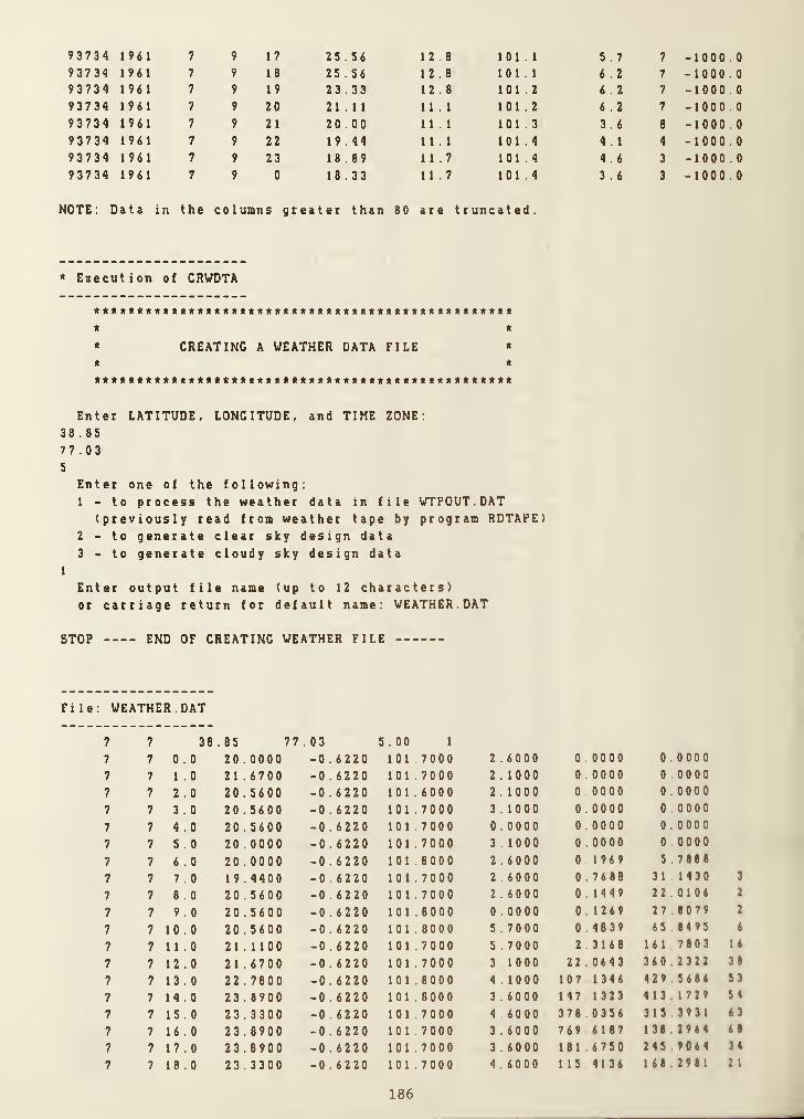
93734 1961 7 9 17 25 .56 12.8 101.1 5 . 7 7 -1000.093734 1961 7 9 18 25.56 12.8 101.1 6 . 2 7 -1000.093734 1961 7 9 19 23 . 33 12.8 101.2 6 . 2 7 -1000.093734 1961 7 9 20 21.11 11.1 101.2 6 . 2 7 -1000093734 1961 7 9 21 20 .00 11.1 101.3 3 . 6 8 -1000093734 1961 7 9 22 19.44 11.1 101.4 4 . 1 4 -1000,093734 1961 7 9 23 18 . 89 11.7 101.4 4 . 6 3 -1 000.093734 1961 7 9 0 18 . 33 11.7 101.4 3 . 6 3 -1000.0
NOTE; Data in the columns greater than 80 are truncated.
* Eaecution of CRVDTA
* *
* CREATING A WEATHER DATA FILE *
* *
Enter LATITUDE, LONGITUDE, and TIME ZONE:
38 . 85
77.035
Enter one of the following:1 - to process the weather data in file WTPOUT.DAT
(previously read from weather tape by program RDTAPE)2 - to generate clear sky design data
3 - to generate cloudy sky design data
1
Enter output file name (up to 12 characters)or carriage return for default name; VEATHER.DAT
STOP END OF CREATING WEATHER FILE
File: WEATHER.DAT
7 7 38 .85 77 . 03 5.00 1
7 7 0 . 0 20 . 0000 -0.6220 1 0 1 . 700 0 2 .6000 0 00 00 0 000 0
7 7 1 . 0 21 .6700 -0 . 6220 1 0 1 .7000 2.1000 0 .0000 0 0000
7 7 2 . 0 20 .5600 -0 .6220 1 0 1 . 6 00 0 2.1000 0 00 0 0 0 000 0
7 7 3 . 0 20 .5600 -0 .6220 1 0 1 .7000 3.1000 0.0000 0 0000
7 7 4.0 20 .5600 -0.6220 1 0 1 .7000 0 .0000 0 00 00 0 . 000 0
7 7 5 . 0 20 . 0000 -0 . 6220 1 0 1 . 7000 3.1000 0 . 0000 0 0000
7 7 6 . 0 20 .0000 -0 .6 220 1 0 1 . 8 00 0 2 . 6000 0 1969 5 788 8
7 7 7 . 0 1 9 . 4400 -0 .62 20 1 0 1 .7000 2 6000 0 76 8 8 31 1430 3
7 7 8 . 0 20.5600 -0.6220 101 . 7000 2.6000 0.1449 22 0106 2
7 7 9 . 0 20 . 5600 -0 .6220 101 .8000 0 . 0000 0.1269 27 80 7 9 2
7 7 10.0 20 .5600 -0 . 6220 101 8000 5.7000 0 48 39 65 8 4 95 6
7 7 11.0 21.1100 -0 . 6220 101 .7000 5 . 7000 2 3168 161 7 80 3 1 6
7 7 12.0 21 . 6700 -0 .6220 101 . 7000 3.1000 220643 360 2 3 22 38
7 7 13.0 22.7800 -0 . 6220 101.8000 4 . 1000 107 1346 429 5 686 53
7 7 14.0 23 . 8900 -0 .6 220 1 0 1 .8000 3.6000 147 1323 4 1 3 1729 54
7 7 15.0 23.3300 -0 . 6220 1 0 1 .7000 4.6000 3 70 . 0 356 315 3 9 3 1 63
7 7 16.0 23.8900 -0 .6 220 101.7000 3.6000 769 6187 138 2 9 6 4 68
7 7 17.0 23 . 8900 -0 .6220 1 0 1 .7000 3.6000 1816750 245 906 4 34
7 7 18.0 23.3300 -0 .6220 1 0 1 .7000 4 .6000 115 4136 161 2 9 8 1 2 1
186

7 7 19 . 0 22 .7800 -0 .6220
7 7 20 . 0 21.6700 - 0 .6220
7 7 21.0 21.1100 - 0 . 6220
7 7 22 . 0 20 . 5600 -0 .6220
7 7 23 . 0 20.5600 - 0 .6220
7 7 24 . 0 20.0000 - 0 . 6220
7 8 1 . 0 20 . 0000 - 0 . 6220
7 8 2 . 0 19.4400 - 0 .6220
7 8 3 . 0 19.4400 - 0 .6220
7 8 4 . 0 19.4400 - 0 .6220
7 8 5 . 0 19 . 4400 - 0 . 6220
7 8 6 . 0 19 . 4400 - 0 .6220
7 8 7 . 0 20 .5600 - 0 .6220
7 8 8 . 0 22 .2200 - 0 .6220
7 8 9 . 0 23 . 3300 - 0 . 6220
7 8 10.0 22 . 7800 - 0 .6220
7 8 11.0 24.4400 - 0 .6220
7 8 12.0 24 .4400 -0 .6220
7 8 13.0 25 . 5600 - 0 . 62207 8 14.0 26 . 6700 - 0 .6220
7 8 15.0 27 . 2200 - 0 . 62207 8 U . 0 26.6700 - 0 .6220
7 8 17.0 26.6700 - 0 .6220
7 8 18 . 0 26 . 1100 - 0 . 62207 8 19 . 0 25 . 0000 -0 . 62207 8 20 . 0 23 . 3300 - 0 .6220
7 8 21 .0 22 . 7800 - 0 . 62207 8 22 . 0 22 . 7800 -0 .6220
7 8 23 . 0 22 . 2200 - 0 . 6220
7 8 24 . 0 21 .6700 -0 .6220
7 9 1 . 0 21.1100 - 0 . 62207 9 2 . 0 20.5600 -0 .6220
7 9 3 . 0 20 . 0000 - 0 . 62207 9 4 . 0 19.4400 - 0 . 6220
7 9 5 . 0 19.4400 - 0 . 6220
7 9 6 . 0 18 . 8900 - 0 .6220
7 9 7 . 0 20 . 0000 - 0 . 62207 9 8 . 0 2 1 .6700 - 0 . 62207 9 9 . 0 22 . 7800 - 0 .6220
7 9 10.0 24.4400 - 0.62207 9 11.0 25 .5600 - 0 .6220
7 9 12.0 27 .2200 - 0 .6220
7 9 13.0 27 . 2200 - 0 . 6220
7 9 14.0 27 .2200 - 0 .6220
7 9 15.0 26 . 6700 - 0 .6220
7 9 U . 0 26.1100 -0. 622 0
7 9 17.0 25 . 5600 -0 .6220
7 9 18.0 25 . 5600 - 0 . 6220
7 9 19.0 23.3300 - 0 .6220
7 9 20 . 0 21.1100 -0 .6220
7 9 21.0 20 . 0000 -0 .6220
7 9 22 . 0 19 . 4400 -0 .6220
7 9 23 . 0 18 . 8900 -0 .62 20
7 9 24 . 0 18.3300 - 0 . 6220
NOTE: Data in the columns greater than
6000 4 . 1000 6.6053 55 .706 6 5
6000 2.6000 0 . 0000 0.0000
7000 2 . 6000 0 .0000 0 .0000
7000 2.1000 0.0000 0.0000
8000 2 .6000 0 . 0000 0.0000
7000 2.6000 0.0000 0.0000
6000 1 .5000 0 .0000 0.0000
6000 0 .0000 0.0000 0.0000
5000 0 . 0000 0.0000 0.00005000 0 .0000 0.0000 0.0000
5000 2.1000 0 .0000 0 .0000
5000 2.1000 0 . 5209 9.2447
6000 2 . 1000 4 .9306 77 .5720 7
6000 0 . 0000 28 . 4925 188.5826 20
6000 2.1000 197.4422 285.1067 41
6000 3 .1000 1 91 . 8022 347.8713 49
5000 2 . 6000 262.0825 376 . 1 01 6 60
5000 2 .6000 237.6303 408 . 2700 63
4000 3.1000 741.7134 197.3627 90
4000 4 .1000 15.9343 331.6353 34
3000 3.1000 300 . 4958 34 1 .8843 59
3000 3.6000 394.5117 2 62 . 85 33 54
2000 3.1000 415.3787 199 . 4689 42
2000 4.1000 211.0219 1 64 . 0207 24
2000 3.1000 4 .9064 49.0572 4
2000 3.1000 0.0000 0.0000
2000 3.1000 0 .0000 0.00002000 3.1000 0 . 0000 0.00002000 2 . 6000 0.0000 0 .0000
1000 2 .6000 0 . 0000 0.0000
1000 2.1000 0.0000 0 .0000
0000 2 .6000 0 . 00 0 0 0 . 000 0
0000 2.1000 0 . 0000 0 .0000
0000 2.1000 0.0000 0.00000000 2 . 1000 0 . 0000 0 .0000
1000 2.6000 18 . 3946 38 . 75 04 4
1000 2 . 6000 235 . 8 9 25 1 26 .32 30 19
2000 2 .6000 5 49 .5 1 64 141.5620 40
2000 3.1000 664.4600 1 55 .3 863 58
2000 2 .6000 72 1 .2656 168.6929 73
1000 0.0000 759.7915 1 76 .3566 85
1000 4.1000 7 66 . 83 62 185.3893 91
1000 5 . 7000 742.5952 1 96 .9268 90
1000 5.1000 638.1118 233 . 0332 81
1000 5.1000 504.5327 265.9695 68
1000 5.7000 89 . 48 78 315.3828 37
1000 5 . 7000 5 04 . 6 8 1 9 1 75 .9 8 6 4 45
1000 6.2000 401.5051 137.2548 28
2000 6 .2000 41.8718 77.0723 8
2000 6 . 2000 0.0000 0 . 0000
30 00 3.6000 0.0000 0.00004000 4.1000 0 . 0000 0.00004000 4.6000 0.0000 0.000040 00 3.6000 0.0000 0.0000
are truncated.
101
101
101
101
101
101
101
101
101
101
101
101
101
101
101
101
101
101
101
101
101
101
101
101
101
101
101
101
101
101
101
101
101
101
101
101
101
101
101
101
101
101
101
101
101
101
101
101
101
101
101
101
101
101
BO
187

B • Simulation
( 1 ) Allocation of Output Files
Default names of the output files are MODSUM.DAT, MODOUT.DAT, and1NIT0UT.DAT.
( 2 ) Eaecution of MODSIM for Initialization
Minimum time step, maaimum time step, and simulation stopping time are
1, 1000, and 66400 seconds, respectively.
( 3 ) Continuation of Simulation
* Execution of MODSIM for Simulation using the Initialization File
**)t«**A**)t***«ftft)k«*****tt**«<M>****«*1tft««**«lt***
* «
* MODSIM Version 5.0 *
* *
«**««*«*«*««««*«*««**«*****«*««**«««*«******«•
Enter MINIMUM TIME STEP, MAXIMUM TIME STEP, and SIMULATION STOPPING TIME
1 , 1 000,259200Is the Building Shell Model used? <N>
Y
Will the Initialization File be called? <N>
Y
What is the INDEX NUMBER of the SUPERBLOCK for the Building ShelP1
ISSHEL =1
Enter the time of day (in hours after midnight)at which the simulation is to begin
0
Use default file names for all files? (Y/N) <Y>
Do you want Diagnostic Information to be written <N>^
Would you like to monitor the Simulation on Screen* <N)
SIMULATION BEGINS-- FIRST WEATHER DATA SET HAS BEEN READ
INITIALIZATION FILE HAS BEEN WRITTENSTOP --END OF SIMULATION ---
* File: MODOUT.DAT (for the second run)
SUPERBLOCK 1 1 . 00
20 . 33 38 1 8 . 7336 20.2245 20.2587 20 2350
20 . 23 46 20 . 3646 20.3762 20 3393 20 0000
2 . 39 2979E-020 .0000 00
2 . 2224 1 lE-02 2 . 28 1 0 7 2E-02 0 000000 0 000000
188

SUPERBLOCK 2 1.00
20 .0006 20 . 0006 20.0190 22.1665 20.0000
7 . 4 00 32 6E-04 7 . 400326E-04 7 . 400324E-04SUPERBLOCK 2 3 . 00
20.0012 20.0012 20 . 03 79 22.1665 20 .0000
7 . 4 00 65 2E-04 7 . 400652E-04 7 . 400645E-04
SUPERBLOCK 2 361.0020.1085 20 . 1 074 21.3665 2 2 . 1 6 65 20.0000
7 . 458397E-04 7 . 458394E-04 7 . 428809E-04
SUPERBLOCK 1 900.0020.2759 19.0246 20.2807 20.2373 20.2915
20.2914 20 . 3087 20 .28 32 20 . 5286 20.7815
2 . 963960E-03 -1 . 935803E-03 -0 . 25 1 706 0.000000 0 .000000
0.000000SUPERBLOCK 2 1030.00
20.2914 20.2848 21.9241 22.1665 20.00007 . 564859E-04 7 . 564828E-04 7 . 447517E-04
SUPERBLOCK 1 1800. 00
20 , 3788 19.1844 20 . 47 44 20 . 35 99 20 .4871
20 . 4858 20 . 3 460 20.3776 20.8428 21.3204
8 . 122213E-04 -5 . 81 3498E-03 -0.318652 0.000000 0.0000000.000000
SUPERBLOCK 2 2030.0020 . 5684 20.5509 22.0615 22 . 1 665 20.0000
7 . 722455E-04 7 . 72231 OE-04 7 . 45609 9E-04
SUPERBLOCK 1 2700.0020.5417 19.3457 20.7105 20 .5468 20.723820,7221 20 . 45 63 20.5410 21.0963 21.6165
-1 . 365668E-02 -1 . 414384E-02 -0 .274801 0 .000000 0.0000000.000000
SUPERBLOCK 2 3030.0020.8199 20 . 80 2 1 22.1027 22.1665 20.0000
7 . 880400E-04 7 . 880139E-04 7 . 459365E-04SUPERBLOCK 1 360 0 . 00
20.7171 19.5224 20.9170 20.7383 20.926820.9277 20.6030 20.7128 2 1 . 2 8 3 7 21.6700
-3 . 207046E-02 -1 . 868834E-02 -0 . 22 6565 0 . 00 00 00 0.0000000.000000
SUPERBLOCK 2 4030.002 1 . 0320 21.0371 22 . 1 258 22.1665 20.0000
8 040539E-04 8 . 04031 7E-04 7 . 4 6 0 90 7E-04
SUPERBLOCK 1 4500.0020 .8678 1 9 .67 88 21.0512 20.8912 21.055621.0583 20.7467 20.8577 21.4103 21.4930
-4. 560097E-02 -1 . 715894E-02 -0
, 1 9 6 9 22 0.000000 0.0000000.000000
SUPERBLOCK 2 5030.0021.2083 21.2612 22.1383 22 . 1 6 6 5 20.0000
8 . 203641E-04 8 . 203788E-04 7 . 4 6 1 55 4 E-04
SUPERBLOCK 1 5400 . 00
20.9771 19.8039 21.1038 21.0048 21.101221.1027 20.8734 20.9925 21 4787 21 1868
-6 . 460547E-02 -6. 795895E-02 -0 185209 0.000000 0 . OOOOCC
0000000SUPERBLOCK 2 6030.00
21.3388 2 1 . 38 47 2 2 . 1 4 2 5 22.1665 20,00008 . 3 6 3 1 1 4E-04 8 . 363035E-04 7 . 4 6 1 2 9 1 F-04
SUPERBLOCK 1 6300.0021.0412 19.8925 21.0877 21.0771 21 077421 .0786 20 9682 21.0801 21 4985 20 8396
189
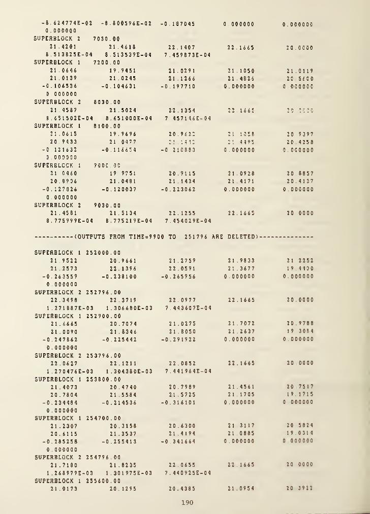
-8. 824774E- 02 -8
. 800596E-02 -0. 137045 0.000000 0.000000
0.000000SUPERBLOCK 2 7030 . 00
21.4201 21.4618 2 2 . 1 40 7 22.1665 20 0 0 0 0
8 . 5 1 3 8 25E- 04 8.513539E-04 7 . 459873E-04SUPERBLOCK 1 7200 . 00
21 .0646 19.9451 21.0291 21.1050 2 1 .011921.0139 21.0245 21.1266 21.4826 20 5 6 0 0
-0. 1 0 6536 -0.104631 -0.197710 0 . 000000 0 000000
0000000SUPERBLOCK 2 803 0 . 00
21.4587 21.5024 22.1354 22.1665 "* ft ft'' ' ft
8 . 65 1 5 0 2E- 04 8.651000E-04 7 457146E-04SUPERBLOCK 1 8100.00
21.0615 19.9696 20.9622 2 1 1 G 5 8 20 9 3 9 7
20.9433 210477 2 1 . 1 4 1
2
21 4495 20 4 25 8
-0.121632 -0116654 -G 21C383 0.000000 0 . CCOOOO0000000
SUPERBLCCK 1 9 0 0 C . 0 0
210460 19.9751 20.9115 210928 20 8 8 5 7
20.8906 21.0481 21.1434 214171 20 4 137
-0.127826 -0 . 1 2 0 0 3 7 -0.223062 0 .00 0000 0.0000000.000000
SUPERBLOCK 2 9030.0021.4581 21.5134 22 . 1 2 55 2 2 . 1 6 65 20 0 0 0 0
8 . 775999E- 04 8.775219E-04 7 . 454029E-04
(OUTPUTS FROM TIME = 9900 TO 25 1 79 6 ARE DELETED)---
SUPERBLOCK 1 25 20 00 . 00
21.9522 20 .9 66 1 2 1 . 27 5 9 21.9833 2 1 2 2 5 2
212573 22 . 1 396 22.0591 21 . 3677 1 9 4 4 0 0
-0.263559 -0.238100 -0 .265956 0 .000000 0 000000
0 000000
SUPERBLOCK 2 252796.0022 . 34 98 22.3719 2 2 . 0977 2 2 . 1 6 65 20 0000
1 . 2 7 1 8 8 7E- 03 1.306680E-03 7 . 443607E-04SUPERBLOCK 1 252900 . 00
21.6665 20 .707 4 2 1 . 0275 2 1 .7072 20 9 78 8
21.0090 21.8346 2 1 . 8 050 212637 1 9 3 0 8 4
-0 . 24 7 862 -0 .225442 -0 .29 1 9 22 0 000000 0 000000
0 .000000
SUPERBLOCK 2 253796 . 00
22 . 0627 22.1211 22 .0852 22 . 1 6 65 20 0 000
1 . 2 70476E- 03 1.304380E-03 7 . 4 4 1 96 4E-04
SUPERBLOCK 1 253800 . 00
2 1 .4073 20 . 4740 20.7989 21.4561 20 7517
20 . 78 04 21 .5584 21 .5725 21.1705 1 9 1715
-0 . 23 4484 -0 .214536 -0.316101 0 .0000 00 0 000000
0 .0 00000SUPERBLOCK 1 254700 . 00
21 .2307 20.3158 20.6300 213117 20 5 8 2 4
20.6115 21 . 3537 21.4194 21 0885 1 9 0314
-0 . 285258 -0 .2554 1 3 -0 .3 4 1 6 64 0.000000 0 000000
0 .000000
SUPERBLOCK 2 254796.0021 . 7180 21.8235 22 .0 655 221665 20 00 00
1 . 268979E- 03 1.301975E-03 7 . 440925E-04
SUPERBLOCK 1 255600 . 00
21.0173 20.1295 20.4385 21 0954 20 3 9 2 2
190

20 . 4205 21.1365 21 . 2273 21.0109 18.8900
-0.241197 -0 .220511 -0 . 359827 0 .000000 0 .000000
0 .000000
SUPERBLOCK 2 255796 . 00
21 . 4541 21 . 5897 22.0548 22 . 1665 20.0000
1 . 267662E- 03 1.299750E-03 7 . 440553E-04SUPERBLOCK 1 256500 . 00
20.8110 19 . 9485 20.2499 20.8892 20 .2050
20 .2323 20.9246 21 .0394 20.9373 18.7490-0 . 220682 -0 .203429 -0 . 380644 0 .000000 0 .000000
0 . 000000SUPERBLOCK 2 256796.00
2 1 .2297 21 .3887 22 . 0451 22 .1 665 20.0000
1 . 266833E- 03 1.298028E-03 7 . 440895E-04SUPERBLOCK 1 257400.00
20.6175 19 . 7789 20.0705 20.6980 20.026820 . 0533 20.7238 20 .8625 20 .8683 18.6086
-0 . 208762 -0 . 193080 -0 . 400627 0 . 000000 0 .000 000
0 .00 0000
SUPERBLOCK 2 257796.0021 . 0301 2 1 .2090 22 .0363 22 . 1 665 20.0000
1 . 26 6805E- 03 1.297132E-03 7 . 441971E-04SUPERBLOCK 1 258300.00
20 .4375 19.6212 19.9016 20.5214 1 9 .8589
19.8849 20 .5357 20 .6978 20 .8033 18.4689-0 .200604 -0 . 185770 -0 .419944 0 .000000 0 . 0000000 .000000
SUPERBLOCK 2 258796 . 00
20 . 8491 21.0461 22.0282 22 . 1665 20 .0000
1 . 267894E- 03 1.297383E-03 7 . 443784E-04SUPERBLOCK 1 259200.00
20 . 2705 19 . 4752 19 . 7435 20 .3584 19.701519.7271 20 . 3605 20 .5448 20 .7424 1 8 . 330 0
-0 . 1 94380 -0 . 180170 -0 . 438363 0 .0000 00 0.0000000 .000000
SUPERBLOCK 2 259200 . 00
20.7811 20 .9849 22 .0223 22.1665 20.00001 . 268553E- 03 1.297710E-03 7 . 444688E-04
C . Postprocessing - Output Data Analysis
Execution of SORTSB program and plotting using the output of SORTSB.
191
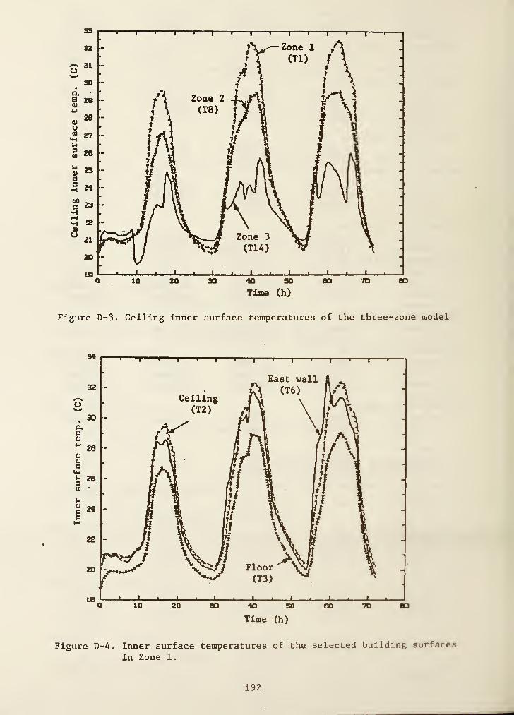
Figure D-3. Ceiling inner surface temperatures of the three-zone model
Figure D-4. Inner surface temperatures of the selected building surfaces
in Zone 1.
192
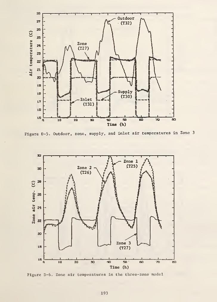
Air
temperature
(C)
Figure D-5. Outdoor, zone, supply, and inlet air temperatures in Zone 3
193

Figure D-7. Convective heat flow rates from the building inner surfaces
Figure D-8. Solar radiation influxes from a weather tape
194
NBS-114A (REV. 2-60)
U.S. DEPT. OF COMM. 1. PUBLICATION ORREPORT NO.
2. Performing Organ. Report No. 3. Publication Date|
BIBLIOGRAPHIC DATASHEET (See instructions) NBSIR-86/3331 MARCH 1986
4. TITLE AND SUBTITLE
HVACSIM"*” Building Systems and Equipment Simulation Program;
Building Loads Calculation
5. AUTHOR(S)
Cheol Park, Daniel R. Clark, George E. Kelly
6. PERFORMING ORGANIZATION (If joint or other than NBS. see instructions)
NATIONAL BUREAU OF STANDARDSDEPARTMENT OF COMMERCEWASHINGTON, D.C. 20234
7. Contract/Grant No.
8. Type of Report & Period Covered
9.
SPONSORING ORGANIZATION NAME AND COMPLETE ADDRESS (Street, City. State. ZIP)
Office of Buildings and Community Systems U,S. Navy Civil Engineering LaboratoryU.S. Department of Energy U.S. Department of Defense1000 Independence Avenue, NW Port Hueneme, CA 93043Washington, DC 20585
10.
SUPPLEMENTARY NOTES
I I
Document describes a computer program; SF-185, FIPS Soft>ware Summary, is attached.
11.
ABSTRACT (A 200-word or less factual summary of most significant information. If document includes a significantbibliography or literature survey, mention it here)
A non-proprietary building system simulation program called HVACSIM"*", which standsfor HVAC SIMulation PLUS other systems, has been developed at the National Bureau of
Standards (NBS) in an effort to understand the dynamic_|_interactions between a buildingshell, an HVAC system, and building controls. HVACSIM consists of a main simulationprogram, a library of HVAC system component models, a building shell model, and inter-active front end input data generation programs.
The main simulation program employs a hierarchical, modular approach and advancedequation solving techniques to perform dynamic simulations of building/HVAC/controlsystems. In the building shell model, a fixed time step selected by the user is
employed, while a variable time step approach is used in the HVAC and control systemsportion of a simulation and the zone model.
This report presents the overall architecture of the HVACSIM program, algorithmsused in the main simulation program, a brief discussion of the numerical methods usedin solving a system of non-linear simultaneous equations. Integrating stiff ordinarydifferential equations and interpolating data and descriptions of the building shelland zone models. Conduction transfer functions, weather data, and simulation procedureare also described. This report is the third document, which describes the buildingmodel, supplied with HVACSIM^.
12.
KEY WORDS (Six to twelve entries; alphabetical order; capitalize only proper names; and separate key words by semicolons)
building dynamics; building simulation; building system modeling; computer simulationprograms; control dynamics; dynamic modeling of building systems; dynamic performance ofbuilding systems; dynamic simulations; HVAC system simulations; HVACSIM"*"
13. AVAILABILITY
rX~[ Unlimited
I IFor Official Distribution, Do Not Release to NTIS
1 I
Order From Superintendent of Documents, U,S, Government Printing Office, Washington, D,C.20402.
02 Order From National Technical Information Service (NTIS), Springfield, VA, 22161
14, NO, OFPRINTED PAGES
202
15. Price
$22.95
USCOMM-DC 0043-P80

..ati'ffl- ® n" '’ ' '
»i(ii»TfeiaEW'a
r.
L'-jiStf-i*»o^‘ ^* >r M'-,
'
”*“ l|lssiAw<
*
CM^rMiir^X.«d'. -fiWQj fjBt);;' Ui4r'i;..
I ^"t.
i "; -£ - I
.
'
i'*'
(liflj.'i u»it*«o .mi-1
k«r Ic^. •
-pithT'WA
’^U'{r»wrVAiiiwiiv»o:' ‘ -< '1
ffMI/ktf f« .M»Atr4lTi^ W9miKt» Jofs *^.TWTfMqwM«l;W *
! _3‘
'f[2
;ids ^lA 4f«i^l"< Wr' n\U• "’Wn*«a ?.0
HtTOh 1 HATIO^ tl»f
^4
1
. - 't.«< nVHWwAu^
' ‘ i^-»W <t f ^
j;” S'. .
fnt^nMa A»±x^^t b noX.itiiJUmH fBniaifi *«lt..'»« y
A
fejo arfjt tO' bfOt|oI^»b *r#iNf' «>'4l' iimr^j^vA AUn iroUAttriff, ;'^n^ tof'
». tnmfy*T.txiu *• 7n»'T>y'TBr7ir'T^ffif> ci" ^ " o ‘iCf?.*#
i' I'tJ U*«« mV<I.#i .J
__ __ ___ ^ ^•J.-A*»(fj \» f^Ariii «' »r»i
bn4j4ii»*6^ »aii#btw .X»aJt4oift3i»tii - i'. .4jai«^Ajf>l*^ tfT ,
!» :»i.<|4--''':^' «"*o^ ’•fO «| i;aiv.lwr fiw im^piX
"iSt.'
x‘5
^isswpjfa^’ tss^f s*#> l4i|.4«b%»'i oS
WMiavo s#»* •fifTl iH»9v i««<vjiiv a
X' '" £ Hr % A W^ifo4'^
aa;^'»iVoaX^'-l4i«T80#^^ 1|» ilA»r.v JJ»4. i %*»<•
b«ep ab<>rfS^ .yy^anttfR Mij io HW'
b«H» «
lyp^iNyi
horfiisiM#
f^i-H
tsfwi <«(»«»* id'*>
?«3«^4oo (^W Hwlinoliti
' JeP'* #ynt }ao<bt:)
a4J I W -
* anlficf.
iilrS xa^Afyin n^ ^ ' M t i.' lJOirtkb 04|4 '
» — ^ 4A *Ui \ ^
i.•fi i*HJ • I 1 f>f|« >
r.b 3|i»)4!'- -4
irih ^r|i *t^af» *«- ^
1^
a -1
*•: Cfcl'
'
'*
'' lfTwai«*^»»4 >K *0
MKDTy^a*# .AVf«%g4l 1
-rife'. ^

