hull equipment and appendages - rules and … · comprehensive information about dnv and the...
TRANSCRIPT

RULES FOR CLASSIFICATION OF
SHIPS
NEWBUILDINGS
HULL AND EQUIPMENT MAIN CLASS
PART 3 CHAPTER 3
HULL EQUIPMENT AND APPENDAGES JANUARY 2000
CONTENTS PAGE
Sec. 1 Sec. 2 Sec. 3 Sec. 4 Sec. 5 App.A
General Requirements ................................................................................................................ 5 Sternframes, Rudders and Steering Gears ................................................................................. 6 Anchoring and Mooring Equipment ....................................................................................... 28 Masts and Rigging .................................................................................................................... 42 Seats for Additional Lifting, Towing or Mooring Equipment ................................................ 45 Additional Requirements for non - duplicated Rudder Actuators ........................................ 48
DET NORSKE VERITAS
Veritasveien I, N-1322 H~vik, Norway Tel.: +47 67 57 99 00 Fax: +47 67 57 9911

CHANGES IN THE RULES
General
The present edition of the rules includes additions and amendments decided by the board as of December 1999, and supersedes the January 1996 edition of the same chapter (including later amendments).
The rule changes come into force 1 July 2000.
This chapter is valid until superseded by a revised chapter. Supplements will not be issued except for minor amendments and an updated list of corrections presented in Pt.O Ch.1 Sec.3. Pt.O Ch.1 is normally revised in January and July each year.
Revised chapters will be forwarded to all subscribers to the rules. Buyers of reprints are advised to check the updated list of rule chapters printed Pt.O Ch.I Sec.I to ensure that the chapter is current.
Main changes
Sec.3 Anchoring and Mooring Equipment In A102 an additional sentence has been added indicating that if certification of materials is needed, voluntarily, then this will be done in accordance with A204.
Comments to the rules may be sent by e-mail to [email protected]
In A204 11 fibre ropes (WY1 has been included in the list of items requiring DNV Product Certificate (NV) for materials, ISO 10474: Type 3.1 C. Where the "(W)" indicates that a work's certificate (for materials, ISO 10474 Type-3.) B) from an approved manufacturer will normally be accepted.
Sec.5 Seats for Additional Lifting, Towing or Mooring Equipment
In A102 it is now stated that the crane pedestal flanges and bolts are only subject to approval when CRANE, DSV or Crane Vessel is requested. The amendment is made to remove any misunderstanding in regard to the material requirements and approval of pedestal flanges and bolts. In A301 the material requirement for pedestal top flanges has been removed.
Corrections and Clarifications
In addition to the above stated rule amendments, some detected errors have been corrected, and some clarifications have been made in the existing rule wording.
For subscription orders or information about subscription terms, please use [email protected] Comprehensive information about DNV and the Society1s services is found at the Web site http://www.dnv.com
© Det Norske Veritas AS Computer Typesetting (FM+SGML) by Division Technology and Products, Det Norske Veritas AS Printed in Norway by Det Norske Veritas AS January 2000.
If any person sutlers loss or damage whlch is proved to have been caused by any negllgent act or omission of Del Norske Veritas, then Det Norske Veritas shall pay compensation to such person for his proved direct loss or damage. However, the compensation shall not exceed an amount equal to ten times the fee charged for the service in question, provided that the maximum compen· sation shall never exceed USD 2 million. In this provision "Det Norske Veritas" shall mean the Foundation Det Norske Veritas as well as all Its subsidiaries, directors, officers, employees, agents and any other acting on behalf of Del Norske Veritas. · -

Rules for Ships, January 2000 Pt.3 Ch.3 Contents - Page 3
CONTENTS
SEC. 1 GENERAL REQUIREMENTS ........................... 5
A. Classification ......................................................................... 5 A I 00 Application ........................................................................ 5
B. Definitions .............................................................................. 5 B I 00 Symbols ............................................................................ 5
C. Documentation ...................................................................... 5 C 100 General.. ............................................................................ 5
SEC. 2 STERNFRAMES, RUDDERS AND STEERING GEARS .................................................................. 6
A. General .................................................................................. 6 A 100 Introduction ....................................................................... 6 A 200 Definitions ........................................................................ 6 A 300 Documentation ................................................................. 7
B. Materials ................................................................................ 8 B I 00 Plates and sections ............................................................ 8 B 200 Forgings and castings ........................................................ 8 B 300 Bearing materials .............................................................. 8 B 400 Material certificates .......................................................... 8 B 500 Heat treattnent ................................................................... 8
C. Arrangement and Details ..................................................... 8 C I 00 Stemframes and rudders ................................................... 8 C 200 Steering gears .................................................................... 9
D. Design Loads and Stress Analysis ....................................... 9 D 100 Rudder force and rudder torque, general ......................... 9 D 200 Rudders with stepped contours ....................................... 10 D 300 Stress analysis ................................................................. 11
E. Sternframes and Rudder Horns ........................................ 11 E 100 General ............................................................................ 11 E 200 Propeller posts ................................................................. 11 E 300 Sole pieces ...................................................................... 12 E 400 Rudder homs ................................................................... 12
F. Rudders ................................................................................ 14 F 100 General arrangement and details ..................................... 14 F 200 Rudder plating ................................................................. 14 F 300 Rudder bending ............................................................... 14 F 400 Web plates ....................................................................... 15 F 500 Single plate rudders ........................................................ 15 F 600 Mounting of rudder ......................................................... 15
G. Rudder Stocks and Shafts .................................................. 15 G 100 General ............................................................................ 15 G 200 Rudder stock with couplings ........................................... 16 G 300 Rudder shaft .................................................................... 18 G 400 Bearings and pin ties ....................................................... 19
H. Propeller Nozzles ................................................................ 20 H 100 General ............................................................................ 20 H 200 Plating ............................................................................. 20 H 300 Nozzle ring stiffness ....................................................... 20 H 400 Welding ........................................................................... 20 H 500 Supports .......................................................................... 21
I. Propeller Shaft Brackets .................................................... 21 I 100 General ............................................................................ 21 I 200 Anangement ................................................................... 21 I 300 Struts ............................................................................... 21 I 400 Welding ........................................................................... 21 I 500 Material ........................................................................... 21 I 600 Testing ............................................................................ 21
J. Steering Gears ..................................................................... 21 J 100 Arrangement and performance ....................................... 21 J 200 Power actuating system, general requirements ............... 22 J 300 Piping systems, relief valve arrangements ...................... 23 J 400 Rudder actuator ............................................................... 23 J 500 Stee~ng gear control and monitoring systems, general ~
requirements .................................................................... 2::i
J 600 J 700 J 800 J 900 J 1000 J 1100
Control gear for steering motOis ..................................... 25 Indications and alarms ................................................... 25 Power supply and distribution ........................................ 25 Emergency power supply ............................................... 26 Operating instructions ..................................................... 26 Additional requirements for oil carriers, chemical carriers and liquefied gas carriers of 10 000 tons gross and upwards ........................................................................... 26
K. Testing .................................................................................. 26 K 100 Stemfrarnes ..................................................................... 26 K 200 Rudders and rudder stock connections .......... : ................ 27 K 300 Steering gears .................................................................. 27 K 400 Trials ............................................................................... 27
SEC. 3 ANCHORING AND MOORING EQUIPMENT ..................................................... 28
A. General ................................................................................. 28 A 100 Introduction ..................................................................... 28 A 200 Documentation ................................................................ 28 A 300 Assumptions ................................................. : ................. 28
B. Structnral Arrangement for Anchoring Eqnipment. ...... 28 B 100 General ........................................................................... 28
C. Eqnipment Specification .................................................... 29 C 100 Equipment number. ......................................................... 29 C 200 Equipment tables ............................................................ 30
D. Anchors ................................................................................ 31 D I 00 General... ......................................................................... 31 D 200 Materials ......................................................................... 31 D 300 Anchor shackle ............................................................... 31 D 400 Testing ............................................................................ 32 D 500 Additional requirements for H.H.P. ("High Holding
Power") anchors .............................................................. 32 D 600 Identification ................................................................... 32
E. Anchor Chain Cables ........................................................ 33 E 100 General... ......................................................................... 33 E 200 Materials ......................................................................... 33 E 300 Heat treatment and material testing ............................... 35 E 400 Breaking test ................................................................... 35 E 500 Proof test... ...................................................................... 35 E 600 Tolerances ....................................................................... 35 E 700 Identification ................................................................... 36 E 800 Repair of defects ............................................................. 36
F. Windlass and Chain Stoppers ........................................... 38 F 100 General design ................................................................ 38 F 200 Materials ......................................................................... 38 F 300 Testing ............................................................................ 39
G. Towlines and Mooring Lines ............................................ 39 G 100 General... ......................................................................... 39 G 200 Materials ......................................................................... 39 G 300 Testing of steel wire ropes .............................................. 39 G 400 Testing of natural fibre ropes .......................................... 40 G 500 Mooring Winches ......................................................... ..41
SEC. 4 MASTS AND RIGGING ................................... 42
A. General ................................................................................. 42 A 100 Introduction ..................................................................... 42 A 200 Assumptions ................................................................... 42 A 300 Definitions ...................................................................... 42 A 400 Documentation ................................................................ 42
B. Materials and Welding ...................................................... .42 B 100 Materials ······························'······················· .. ················· 42 B 200 Welding ........................................................................... 43
C. Arrangement and Support ................................................. 43 C 100 Masts and posts .............................................................. .43 C 200 Standing rigging ............................................................. .43
DET NORSKE VERITAS
· Rules for Ships, January 2000 Pt.3 Ch.3 Contents - Page 4
D. Design and Scantlings ......................................................... 43 D 100 General .......................................................................... ..43 D 200 Unstayed masts and posts with derricks ......................... 43 D 300 Stayed masts or posts with derricks with a lifting capacity
not exceeding 10 t .......................................................... .43 D 400 Stayed masts of posts with derricks with a lifting capacity
of 10 tor more, but not exceeding 40 t ........................... 43 D 500 Stayed masts without derricks ........................................ .44 D 600 Shrouds ............................................................................ 44
SEC. 5 SEATS FOR ADDITIONAL LIFTING, TOWING OR MOORING EQUIPMENT ...... 45
A. Crane Pedestals and Miscellaneous Lifting Posts ........... .45 A 100 Introduction ................................................................... .45 A 200 Documentation ................................................................ 45 A 300 Materials and welding .................................................... .45 A 400 Arrangement. .................................................................. .45 A 500 Design loads ................................................................... .45 A 600 Allowable stresses .......................................................... .46
B. Seatings for Winches, Windlasses and other Pulling Accessories ........................................................................... 46
B l 00 Introduction .................................................................... .46 B 200 Documentation ................................................................ 46 B 300 Design loads ................................................................... .47 B 400 Calculation of stresses ..................................................... 47 B 500 Allowable stresses. Materials .......................................... 47
APP. A ADDITIONAL REQUIREMENTS FOR NON -DUPLICATED RUDDER ACTUATORS ...... 48
A. Introduction ........................................ :: .............................. 48 A 100 Scope ................................................ : ............................ ..48
B. Materials .............................................................................. 48 B 100 Special Requirements ...................................................... 48
C. Design ................................................................................... 48 C 100 Design pressure ............................................................... 48 C 200 Analysis .......................................................................... .48 C 300 Dynamic loads for fatigue and fracture mechanics
analysis ............................................................................ 48 C 400 Allowable stresses .......................................................... .48 C 500 Burst test ................................................................ : ....... .48
D. Construction Details ........................................................... 48 D l 00 General ........................................................................... .48 D 200 Welds ............................................................................. .48 D 300 Oil seals .......................................................................... .48 D 400 Isolating valves .............................................................. .48 D 500 Relief valves ................................................................... .49
E. Testing .................................................................................. 49 E 100 Non-destructive testing ................................................... 49 E 200 Other testing ................................................................... .49
DET NORSKE VERITAS

Rules for Ships, January 2000 Pt.3 Ch.3 Sec.1 - Page 5
SECTIONl GENERAL REQUIREMENTS
A. Classification
A 100 Application 101 The Rules in this chapter apply to steering arrangement and anchoring, mooring and load handling equipment.
102 Necessary strengthening of the hull structure due to loads imposed by the equipment and installations are given where appropriate.
B 100 Symbols 101
B. Definitions
L Rule length in m 1) B = Rule breadth in m l)
D = Rule depth in m 1) T = Rule draught in m 1)
~ = Rule displacement in t 1 l Cs = Rule block coefficient 1)
V = maximum service speed in knots on draught T
1) For details see Ch.1 Sec.I B
C. Documentation
C 100 General
101 Plans and particulars to be submitted for approval or information are specified in the respective sections of this chapter.
102 For instrumentation and automation, including computer based control and monitoring, see Pt.4 Ch.5 Sec. I.
DET NORSKE VERITAS

Rules for Ships, January 2000 Pt.3 Ch.3 Sec.2 - Page 6
SECTION2 STERNFRAMES, RUDDERS AND STEERING GEARS
A. General
A 100 Introduction
101 Requirements to side thrusters and other appliances intended for manoeuvring or positioning purposes are given in Pt.4 Ch.2.
A 200 Deimitions
201 Main steering gear means the machinery, rudder actuator(s), the steering gear power units, if any, and ancillary equipment and the means of applying torque to the rudder stock (e.g. tiller or quadrant) necessary for effecting movement of the rudder for the purpose of steering the ship under normal service conditions.
202 Auxiliary steering gear means. the equipment other than any part of the main steering gear necessary to steer.the ship in the event of failure of the main steering gear but not including the tiller, quadrant or components serving the same purpose.
203 Steering gear control system means the equipment by which orders are transmitted from the navigating bridge to the steering gear power units. Steering gear control systems comprise transmitters, receivers, hydraulic control pumps and their associated motors, motor controllers, piping and cables.
204 Rudder actuator means the component which converts directly hydraulic pressure into mechanical action to move the rudder.
205 Steering gear power unit means:
RUDDER CARRIER WllH STUFFING SOX
HOR. FL. COUPLING TYPE A \
r--E===tJ
RUDDER BLADE
dso RUDDER STOCK
STEERING GEAR FLAT
BALANCE RUDDER WITH SHAFT
I) in the case of electric steering gear, an electric motor and its associated electrical equipment;
2) in the case of electrohydraulic steering gear, an electric motor and its associated electrical equipment and connected pump;
3) in the case of other hydraulic steering gear, a driving en-gine and connected pump.
206 Power actuating system means the hydraulic equipment provided for supplying power to turn the rudder stock, comprising a steering gear power unit or units, together with the associated pipes and fittings, and a rudder actuator. The power actuating systems may share common mechanical components, i.e. tiller quadrant and rudder stock, or components serving the sarue purpose.
207 Maximum ahead service speed is the maximum speed corresponding to maximum nominal shaft RPM and corresponding engine MCR in service at sea on summer load waterline.
208 Maximum astern speed is the speed which it is estimated the ship can attain at the designed maximum astern power at the deepest seagoing draught.
209 Maximum working pressure means the maximum oil pressure in the system when the steering gear is operated to comply with Jl02. 210 For terms redundancy and independence see Pt.4 Ch. l Sec.I.
211 Some terms used for rudder, rudder stock and supporting structure are shown in Fig. I.
dso
RUDDER TRUNK
RUDDER BLADE
BALANCE RUDDER WITH HEEL P1NTLE
DET NORSKE VERITAS

RUDDER CARRIER WITH STUFFING BOX
NECK BEARING
HOR. FL. COUPLING
Rules for Ships, January 2000 Pt.3 Ch.3 Sec.2 - Page 7
dso
STEERING GEAR FLAT
ds RUDDER STOCK
TYPE B
SEMI-SPADE RUDDER
RUDDER HORN
HORN PINTLE
RUDDER BLADE
Fig. I Rudders
212 Symbols:
f, = material factor, see B Pm = FR = MTR= A
maximum bearing surface pressure, see B design rudder force, see D design rudder torque, see D total area in m2 of rudder blade
H mean rudder height in m.
A 300 Documentation 301 Plans etc. as specified below are to be submitted for approval:
sternframe, horn and propeller brackets, outline of the propeller rudder including details of bearings, shaft, pintles and rudder lock arrangement rudder stock including details of couplings, bolts and keys rudder carrier sectional drawing of rudder actuator dimension drawings for torque transmitting parts and parts subject to internal hydraulic pressure foundation bolts and chocks rudder stoppers piping (and function) diagram according to Pt.4 Ch.I schematic diagrams for:
power supply arrangement motor control systems (detailed requirements for the diagrams are given in Pt.4 Ch.4 for electrical installations)
calculations according to K402 and K403 if sea trials are planned to be carried out in a load condition not providing fully submerged rudder. Such calculations are at least to include evaluation of expected trial loads (torque and support reaction forces) on the actuator versus calculated rudder torque fully submerged and at trial conditions taking
SPADE RUDDER
into account the friction losses and any back pressure in the return side.
The plans are to give full details of scantlings and arrangement as well as data necessary for verifying scantling calculations together with proposed rated torque. Set pressure for all relief valves are to be specified. Material specifications and particulars about heat treatment are also required.
302 For important components of welded construction (e.g. rudder, rudder stock, tiller), full details of the joints, welding procedure, filler metal and heat treatment after welding are to be specified on the plans.
303 Procedure for stress relieving of nodular cast iron and cast steel parts, when dimensional stability is important (such as tiller and rotor, see B502), is to be specified on the plans.
304 Plans of the following items are to be submitted for information:
general arrangement drawings of steering gear and steering gear compartment installation instructions for steering gear (inclusive fitting to rudder stock) locking or brake arrangement steering gear relief valve discharge characteristics (pressure-flow diagram) total delivery capacity of steering gear hydraulic pumps operation instructions (according to JIOOO).
305 Steering gear manufacturers who intend their product to comply with the requirements of the IMO Guidelines for nonduplicated rudder actuators, see Appendix A, are to submit documentation as specified in the guidelines when plans are forwarded for approval.
306 For instrumentation and automation, including computer based control and monitoring, see PtA Ch.5 Sec.!.
DET NORSKE VERITAS
· Rules for Ships, January 2000 Pt3 Ch.3 Sec.2 - Page 8
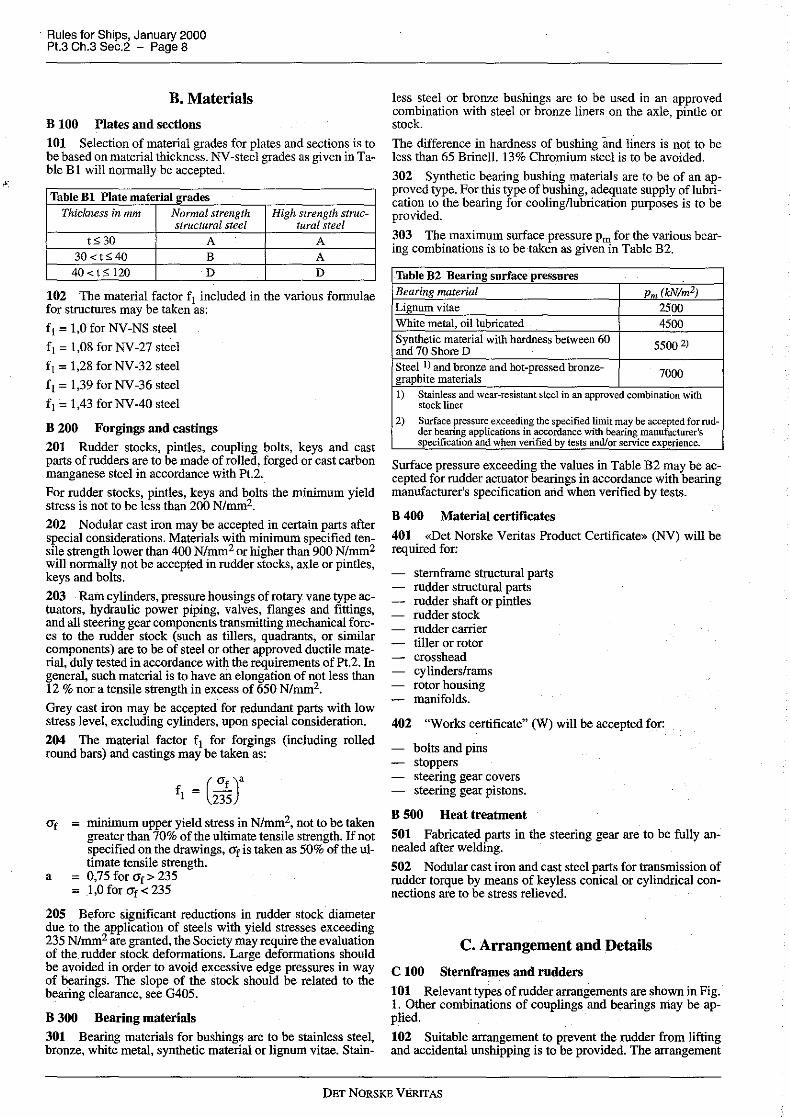
B. Materials
B 100 Plates and sections
101 Selection of material grades for plates and sections is to be based on material thickness. NV-steel grades as given in Table B 1 will normally be accepted.
Table Bl Plate material grades Thickness in mm Normal strength High strength struc-
structural steel tural steel
t530 A A 30<t540 B A 40<t5120 D D
102 The material factor f1 included in the various formulae for structures may be taken as:
f1=1,0 for NV-NS steel
f1 =1,08 forNV-27 steel
f1 =1,28 for NV-32 steel
f1 = 1,39 for NV-36 steel
f1=1,43 forNV-40 steel
B 200 Forgings and castings
201 Rudder stocks, pintles, coupling bolts, keys and cast parts of rudders are to be made of rolled, forged or cast carbon manganese steel in accordance with Pt.2.
For rudder stocks, pintles, keys and bolts the minimum yield stress is not to be less than 200 N/mm2.
202 Nodular cast iron may be accepted in certain parts after special considerations. Materials with minimum specified tensile strength lower than 400 N/mm2 or higher than 900 N/mm2 will normally not be accepted in rudder stocks, axle or pintles, keys and bolts.
203 Ram cylinders, pressure housings of rotary vane type actuators, hydraulic power piping, valves, flanges and fittings, and all steering gear components transmitting mechanical forces to the rudder stock (such as tillers, quadrants, or similar components) are to be of steel or other approved ductile material, duly tested in accordance with the requirements of Pt.2. In general, such material is to have an elongation of not less than 12 % nor a tensile strength in excess of 650 N/mm2•
Grey cast iron may be accepted for redundant parts with low stress level, excluding cylinders, upon special consideration.
204 The material factor f 1 for forgings (including rolled round bars) and castings may be taken as:
O'f = minimum upper yield stress in N/mm2, not to be taken greater than 70% of the ultimate tensile strength. If not specified on the drawings, O'f is taken as 50% of the ultimate tensile strength.
a = 0,75 for O'f > 235 = 1,0 for O'f < 235
205 Before significant reductions in rudder stock diameter due to the application of steels with yield stresses exceeding 235 N/mm2 are granted, the Society may require the evaluation of the rudder stock deformations. Large deformations should be avoided in order to avoid excessive edge pressures in way of bearings. The slope of the stock should be related to the bearing clearance, see G405.
B 300 Bearing materials
301 Bearing materials for bushings are to be stainless steel, bronze, white metal, synthetic material or lignum vitae. Stain-
less steel or bronze bushings are to be used in an approved combination with steel or bronze liners on the axle, pintle or stock
The difference in hardness of bushing and liners is not to be less than 65 Brine!!. 13% Chromium steel is to be avoided.
302 Synthetic bearing bushing materials are to be of an approved type. For this type of bushing, adequate supply oflubrication to the bearing for cooling/lubrication purposes is to be provided.
303 The maximum surface .pressure Pm for the various bearing combinations is to be taken as given in Table B2.
.Table B2 Bearing surface pressures Bearing material Pm (kN!m2)
Lignum vitae 2500 White metal, oil lubricated 4500 Synthetic material with hardness between 60 5500 2) and 70 Shore D Steel I) and bronze and hot-pressed bronze-
7000 graphite materials l) Stainless and wear-resistant steel in an approved combination with
stock liner
2) Surface pressure exceeding the specified limit may be accepted for rud-der bearing applications in accordance with bearing manufacturer's specification and when verified by tests and/or service experience.
Surface pressure exceeding the values in Table B2 may be accepted for rudder actuator bearings in accordance with bearing manufacturer's specification and when verified by tests.
B 400 Material certificates
401 «Det Norske Veritas Product Certificate» (NV) will be required for:
stemframe structural parts rudder structural parts rudder shaft or pintles rudder stock rudder carrier tiller or rotor crosshead cylinders/rams rotor housing manifolds.
402 "Works certificate" C:Wl will be accepted for:
bolts and pins stoppers steering gear covers steering gear pistons.
B 500 Heat treatment
501 Fabricated parts in the steering gear are to be fully annealed after welding.
502 Nodular cast iron and cast steel parts for transmission of rudder torque by means of keyless conical or cylindrical connections are to be stress relieved.
C. Arrangement and Details
C 100 Sternframes and rndders
101 Relevant types of rudder arrangements are shown in Fig. I. Other combinations of couplings and bearings may be applied.
102 Suitable arrangement to prevent the rudder from lifting and accidental unshipping is to be provided. The arrangement
DET NORSKE VERITAS

is to effectively limit vertical movement of rudder in case of extreme (accidental) vertical load on rudder.
103 Effective means are to be provided for supporting the weight of the rudder without excessive bearing pressure, e.g. by a rudder carrier attached to the upper part of the rudder stock. The hull structure in way of the rudder carrier is to be suitably strengthened.
104 If the rudder trunk is open to the sea, a seal or stuffing box is to be fitted above the deepest load waterline, to prevent water from entering the steering gear compartment and the lubricant from being washed away from the rudder carrier.
An additional seal of approved type is required when the rudder carrier is below the summer load waterline.
105
Guidance note:
The after body should be so shaped as to ensure a proper flow of water to the propeller, and _so as to prevent uneven fonnation of eddies as far as possible. The apex of the waterlines in front of the propeller should have the least possible radius, together with a relatively small angle <J>. Plane or approximately plane parts above the propeller tip should be avoided.
The strength of pressure impulses from propeller to hull will normally decrease with increasing clearances. However, even with large clearances to the propeller, a hull may be exposed to strong impulses if the propeller is subject to heavy cavitation.
For a moderately cavitating propeller, the following minimum clearances are proposed (see Table Cl and Fig. 2):_
Table Cl Minimum clearances For single screw ships: For twin screw ships: a;e0,2R (m) b;, (0,7 -0,04 Zp) R (m) c > (0,48 - 0,02 Zp) R (m) c > (0,6 -0,02 Zp) R (m) e;, 0,07 R (m)
R =propeller radius in m Zp ;;;;nwnber of propeller blades.
---e-n-d---of---G-u-i-d-a-n-c-e---n-o-t-e---
Fig. 2 Propeller clearances
106
Guidance note:
107
Rules for Ships, January 2000 Pt.3 Ch.3 Sec.2 - Page 9
A = TL [1 + SOC 2(!!)2
] (m 2
) 100 B L
For ships which frequently manoeo\lre iri harbours, canals or other narrow waters, the rudder area determined by the formula should be increased. For ships with a streamlined rudder post, half of the lateral area of the post may be included in the rudder area. For ships with a rudder horn, the whole area of the horn laying below a horizontal line from the top of the rudder may be included. Rudders not working directly behind a propeller should have the area as given above, increased by at least 30o/o.
Rudders with special profiles or special configurations (e.g. flaps or nozzles) giving increased efficiency may have smaller total areas.
For ships with large freeboard and/or high continuous superstructures an increase of the rudder area ought tO be considered.
Larger rudder area may result in excessive heeling angle when using the rudder in extreme position at full speed ahead. This is particularly relevant for passenger vessels, ferries, vehicle ro/ro carriers and other vessels where the combination of speed, draught, vertical centre of gravity and metacentric height may result in excessive heeling angle in case of smaller turning circles. For estimating the result aiJ.gle of heel, reference is made to Pt.5 Ch.2 Sec.2 K400. In cases where the resulting angle of heel may exceed 10 degrees, the Master should be provided with warning about this in the stability manual.
---e-n-d---of---G-u-i-d-a-n-c-e---n-o-t-e---
Guidance note: In order to minimise vibrations, the balancing and design of the rudders should be carried out as follows:
the balanced portion should not be greater than 23% of the total area of the rudder the length of the balanced part at any horizontal section should noWhere be greater than 35% of the total length of the rudder the widest part of the rudder section should preferably be at least 30% aft of the leading edge of the rudder section considered.
---e-n-d---of---G-u-i-d-a-n-c-e---n-0-t-e---
108 Over-balanced rudders are subject to special consideration with respect to type of steering gear and risk of an unexpected and uncontrolled sudden large movement of rudder causing severe change of ship's pre-set course. See J106.
Guidance note: A rudder shall be considered over-balanced, when balanced portion exceed 30% in any actual load condition. Special rudder types, such as flap rudders, are subject to special consideration.
---e-n-d---of---G-u-i-d-a-n-c-e---n-o-t-e---
C 200 Steering gears
201 F()r arrangement and details of steering gear see subsection J.
D. Design Loads and Stress Analysis
D 100 Rudder force and rudder torque, general
101 The rudder force upon which the rudder scantlings are to be based is to be detennined fromthe following formula:
FR= 0,044 k1 k2 k3 A V2 (kN)
Rudders (one or more) working directly behind a propeller A should preferably have a total area not less than:
= area of rudder blade in m2, including area of flap. = vertical projected area of nozzle rudder
DET NORSKE VERITAS.

Rules for Ships, January 2000 Pt.3 Ch.3 Sec.2 - Page 1 O
coefficient depending on rudder profile type (see Fig. 3):
Table Dl Rudder profile type - coefficient Profile type Ahead Astern
NACA - Gottingen 1,1 0,8 Hollow profile l) 1,35 0,9
Flatsided 1, 1 0,9
Profile with «fish tail» 1,4 0,8
Rudder with flap 1,65 1,3
Nozzle rudder 1,9 1,5 I)
H
v
Profile where the width somewhere along the length is 75% or less of the width of a flat side profile with same nose radius and a straight line tangent to after end
coefficient depending on rudder/nozzle arrangement = 1,0 in general = 0,8 for rudders which at no angle of helm work in the
propeller slip stream I, 15 for rudders behind a fixed propeller nozzle H2 - + 2 not to be taken greater than 4 A, mean height in m of the rudder area. Mean height and mean breadth B of rudder area to be calculated as shown in Fig. 4 total area of rudder blade in m2 including area of flap and area of rudder post or rudder horn, if any, within the height H.
= maximum service speed (knots) with the ship on summer load waterline. When the speed is less than IO knots, V is to be replaced by the expression:
V-=V+20 min 3
For the astern ·condition the maximum _astern -speed· is to be used, however, in no case less than:
Vastem = 0,5 V The maximum service speed corresponds to tl!e maximum continuous rating (MCR) of the engine. In special ship types (such as tugs) the maximum output of the propelling machinery may exceed MCR by more than 15%. In such cases Vis to be increased by the following percentage:
Table D2 Percentage increase in MCR vs V Maximum engine output
.
above nonnal (%) 15 20 25 30 35 40
V increase(%) 3 5 7 9 . 11 12
102 The rule rudder torque is to be calculated for both the ahead and astern condition according to the formula:
FR = x. = B = a =
=
k =
Ap =
A =
MTR= FR Xe (kNm)
=minimum 0,1 FR B
as given in IOI for ahead and astern conditions B (a-k) (m) mean breadth of rudder area, see Fig. 4 0,33 for ahead condition 0,66 for astern condition
AF
A
area in m2 of the portion of the rudder blade area situ~ ated ahead of the center line of the rudder stock rudder blade area as given in IOI.
For special rudder designs (such as flap rudders) direct calculations of rudder torque, supported by measurements on simi-
lar rudders, may be considered as basis for rudder torque estimation.
~NACAGOttingen
------------·--->-.Hollow
-----=======~=====) Flatsided
-EES=~· :::=-======~ Fish tail
Rudder profiles.
Fig. 3 Rudder proflles
D 200 Rudders with stepped contours
201 The total rudder force FR is to be calculated according to IOI, with height and area taken for the whole rudder.
202 The pressure distribution over the rudder area may be determined by dividing the rudder into relevant rectangular or trapezoidal areas, see e.g. Fig. 5. The rule rudder torque may be determined by:
n
MTR = L (FRixei) (kNm) i = 1
= minimum 0, 1 FR Xem
n = number of parts = integer
A. FRi = -2F
A R
x ei = Bi (a -Js) ~ (AA;B;)
Xem= L. i = 1
A; = partial area in m2
Bi = mean breadth of part area, see Fig. 4 a as given in 102
For parts of a rudder behind a fixed structure such as a rudder horn: ·
a = 0,25 for ahead condition
= 0,55 for astern condition
A iF = rudder part area forward of rudder stock centre line, see Fig. 5
FR and A as given in I02.
DET NORSKEVERITAS

z
4
~ B-''
I H Z3 +Z1-Z2
2
I i i . ---T·--r . ;_,3
,,_, __ B --r,.-.i
mean breadth of rudder
mean heLght of rudder
---·--- -- - - -- ___ ::(_~_ x
Fig.4 Rudder dimensions
Fig. 5 Rudder area distribution
D 300 Stress analysis
301 The rudder force and resulting rudder torque as given in 100 and 200, causes bending moments and shear forces in the rudder body, bending moments and torques in the rudder stock, supporting forces in pintle bearings and rudder stock bearings and bending moments, shear forces and torques in rudder horns and heel pieces.
The bending moments, shear forces and torques as well as the reaction forces are to be determined by a direct calculation or by approximate simplified formulae as given in the following.
For rudders supported by sole pieces or rudder horns these structures are to be included in the calculation model in order to account for the elastic support of the rudder body.
Acceptable direct calculation methods are given in Classification Note No. 32.1 "Strength Analysis of Rudder Arrangements". For rudder horns, see also E404.
302 Allowable stresses for the various strength members are given in subsections E to J.
For evaluation of angular deflections, see B205 and 0405.
Rules for Ships, January 2000 Pt.3 Ch.3 Sec.2 - Page 11
E. Sternframes and Rudder Horns
E 100 General
101 Stemfrarnes and rudder horns are to be effectively attached to the surrounding hull structures. In particular the stem bearing or vertical coupling flange for rudder axle is to be appropriately attached to the transom floor adjacent to the rudder stock.
For semi-spade and spade rudder arrangements structural continuity in the transverse as well as the longitudinal direction is to be specially observed.
102 Cast steel stemfrarnes and welded stemfrarnes are to be strengthened by transverse webs.
Castings are to be of simple design, and sudden changes of section are to be avoided. Where shell plating, floors or other structural parts are welded to the stemfrarne, there is to be a gradual thickness reduction towards the joint.
Steel forgings and castings for stemfrarnes, rudder horns and rudders are to be in accordance with the requirements in Pt.2 Ch.2 Sec.5 Band Sec.7 B for general applications.
103 Depending on casting facilities, larger cast steel propeller posts are to be made in two or more pieces. Sufficient strength is to be maintained at connections. The plates of welded propeller posts may be welded to a suitable steel bar at the after end of the propeller post.
104 Stresses determined by direct calculations as indicated in D300 are normally not to exceed the following values:
Normal stress: CJ= 80 f1 (N/mm2) Shear stress : "'= 50 f 1 (N/mm2) Equivalent stress : a0 = 120 f1 (N/mm2)
E 200 Propeller posts
201 The boss thickness at the bore for the stem tube is not to be less than:
t = 5 )dp - 60 (mm)
dp = rule diameter of propeller shaft in mm.
202 The scantlings of fabricated propeller posts are not to be less than:
l = 53JL (mm)
b = 37JL (mm)
t = 2, 4JL (mm)
Fi l, b and t are as shown in Fig. 6 Alt. I.
Where the section adopted differs from the above, the section modulus about the longitudinal axis is not to be less than:
Z _ 1, 35LJL ( 3) w - cm fl
203 The scantlings of cast steel propeller posts are not to be less than:
l = 40JL (mm)
b = 30JL (mm)
DET NORSKE VERITAS

Rules for Ships, January 2000 Pt.3 Ch.3 Sec.2 - Page 12
t1 = 3 ,jL (mm)
Jfi t2 = 3, 7 ,jL (mm)
Jfi l, b, t1 and t2 are as shown in Fig. 6 Alt. II.
Where the section adopted differs from the above, the section modulus about the longitudinal axis is not to be .less than:
Z _ I, 3L,}L ( 3) c - cm
fl When calculating the section modulus, adjoining shell plates within a width equal to 53 ,JL from the after end of the post may be included.
ALT. I
---·--- b
303 The section modulus of the sole piece about a horizontal axis abaft the forward edge of the propeller post is in no place to be less than:
304 The sectional area of the sole piece is not to be less than:
0, !FR 2 As= -- (cm)
fl
E 400 Rudder horns
401 The section modulus requirement of the rudder horn about a longitudinal axis is given by:
lh = vertical distance in m from the middle of the horn pintle bearing to the section in question
Yh = vertical distance in m from the middle of the rule pin tie bearing to the middle of the neck bearing
F Ri = part of rudder force acting on the i-th part of the rudder area, see 0202
y ei = vertical distance in m from the centroid of the i-th part of the rudder area to the middle of the neck bearing
n = number of rudder parts
b For the straight part of the rudder horn the section modulus may be taken for the total sectional area of the horn.
Fig.6 Propeller posts
E 300 Sole pieces 301 The sole piece is to be sloped in order to avoid pressure from keel blocks when docking. The sole piece is to extend at least two frame spaces forward of forward edge of the propeller boss. The cross section of this extended part may be gradually reduced to the cross section necessary for an efficient connection to the plate keel.
302 The section modulus requirement of the sole piece about a vertical axis abaft the forward edge of the propeller post is given by:
6, 25FRls 3 Z 1 = (cm )
fl
l, = distance in m from the centre line of the rudder stock to the section in question. l, is not to be taken less than half the free length of the sole piece.
When the connection between the rudder horn and the hull structure is designed as a curved transition into the hull plating the section modulus requirement as given above is to be satisfied by the transverse web plates as follows:
n 3 L bi ti
= i = I 2' 0, 45Z 6000bmax
n ;:: number of transverse webs bi = effective breadth in mm of web no. i. (including the
flange thickness) ~ = thickness in mm of web no. i bmax = largest bi.
Z, bi and bmax are to be taken at a horizontal section 0, 7 r above the point where the curved transition starts (r = radius of curved part, see Fig. 7).
The formula for Zw is based on the material in web plates and shell plate being of the same strength.
For a cast rudder horn any vertical extension of the side plating (see Fig. 8) may be included in the section modulus.
DET NORSKE VERITAS

RANSITION AREA
b
b
·bi
SECTION A-A
Fig. 7 Curved plate transition rudder horn/shell plating
Fig.8 Curved cast transition rudder horn/shell plating
Rules for Ships, January 2000 Pt.3 Ch.3 Sec.2 - Page 13
402 . The rudder horn thickness requirement is given by:
l!OkFReh t = ~~~c·(mm)
f1As ..
k 50 =
eh horizontal projected distance in m from the centre line of the horn pintle to the centroid of As
As area in crn2 in horizontal section enclosed by the horn.
For a curved transition between horn plating and shell plating the thickness of the transition zone plate is not to be less than:
s
z
2 t = 0, 15(s -40) Z (mm) c r ZA
;;;: spacing between transverse webs in mm = radius of curved transition in mm = section modulus at section immediately below the
transition zone section modulus requirement in same section, as given in 401.
403 The vertical parts of the rudder horn participating in the strength against transverse shear are to have a total area in horizontal section given by:
c =
= AH =
A =
0, 3FR 2 Aw= C-- (cm)
fl
( (A+ AH)AH)
1 + A 2 at upper end of horn
1,0 at lower end area of horn in m2. At intermediate sections AH should be taken for part of horn below section total area of rudder in m2.
In a curved transition zone the thickness of the transverse web plates is not to be less than:
1r=0,8J;, (mm)
10 = thickness of curved plate
In the transition zone the curved shell plate is to be welded to the web plates by full penetration weld or by a fillet weld with throat thickness not less than:
t = 0,55 f 11r (mm)
404 A direct stress analysis of the rudder horn, if carried out, is to be based on a finite element method.
For a curved transition to the hull structure the maximum allowable normal and equivalent stresses as given in 104, may in the curved plate be increased to:
er= 120 f1 N/mm2
<Ye= 180 f1 N/mm2
A fine-mesh finite element calculation will be considered as an acceptable method.
In the web plates the normal stresses should not exceed er= 130 f1 N/mm2 ..
405 For a curved transition between the horn side plating and the shell plating, the side plate thicknesses given in 401 to 404 are to be extended to the upper tangent line of the curved part.
DET NORSKE VERITAS

Rules for Ships, January 2000 Pt.3 Ch.3 Sec.2 - Page 14
The transverse web thicknesses are to be kept to the same level and are to be welded to the floors above. No notches, scallops or other openings are to be taken in the transition area.
The alternative design is to carry the side plating of the rudder horn through the shell plate and connect it to longitudinal girders (see Fig. 9), or weld it to the shell plate in line with longitudinal girders. In the latter case the welds below and above the shell plate are to be full penetration welds, and the shell plate is to be specially checked for lamellar tearing. The transverse girders are to be connected to/supported by transverse floors.
Floor plating welded to rudder horn web plates is to have a thickness not less than 75% of the web plate thickness.
406 The lower end of the rudder horn is to be covered by a horizontal plate with thickness not less than the side plating.
OjO ............. ......L_ I! _J.,.-,,.,,,.,,,--
T Li
Fig. 9 Shell plating connected to longitudinal girders in line with rudder horn sides
F. Rudders
F 100 General arrangement and details
101 Rudders are to be double plate type with internal vertical and horizontal web plates.
The rudder body is to be stiffened by horizontal and vertical webs enabling it to act as a girder in bending.
Single plate rudders may be applied to smaller vessels of special design and with service restrictions, see 500.
102 All rudder bearings are to be accessible for measuring of wear without lifting or unshipping the rudder.
Guidance note: In case cover plates are permanelltly welded to the side plating, it is recommended to arrange peep holes for inspection of securing of nuts and pintles.
---e-n-d---of---G-u-i-d-a-n-c-e---n-o-t-e~--
103 Great care is to be taken in highly stressed connections such as:
welds between rudder side plating and upper heavy par1 of rudder at stock coupling welds around cut-outs in semi-spade rudders and openings for demounting of cone coupling and pintles.
104 Welds between plates and heavy pieces (cast or very thick plating) are to be made as full penetration welds, preferably to cast or welded on ribs. Where back welding is impossible welding is to be performed against backing bar or equivalent.
105 Webs are to be connected to the side plates in accordance with Ch.I Sec.12.
Slot-welding is to be limited as far as possible. Horizontal slots in side plating in areas with large bending stresses are to be completely filled by welding.
Normally, slots of length 75 mm and a breadth of 2 t (where t =rudder plate thickness), with a distance of 125 mm between ends of slots, will be accepted. In areas where slots are required to be completely ftlled by welding, more narrow slots with inclined sides (mirtimum 15° to the vertical) and a mirtimum opening of 6 mm at bottom may be used. A continuous slot weld may, however, in such cases be more practical.
106 Plate edges at corners in cut-outs and openings in rudder side plating are to be ground smooth in those par1s of the rudder where high stresses will occur.
107 Means for draining the rudder completely after pressure testing or possible leakages is to be provided. Drain plugs are to be fitted with efficient packing.
108 Internal surfaces are to be covered by a corrosion-resistant coating after pressure-testing and possible stress-relieving.
109 For testing of rudder, see K.
F 200 Rodder plating 201 The thickness requirement of side, top and bottom plating is given by:
t = S, Skas JT + O, ~FR+ 2, 5 (mm)
Jfi 1 1-0 s(~)2 , , b
maximum 1,0
s = the smaller of the distances between the horizontal or the vertical web plates in m
b = the larger of the distances between the horizontal or the vertical web plates in m.
In no case the thickness is to be less than the minimum side plate thickness as given in Ch. I Sec.7 ClOl or Ch.2 Sec.6 C102.
F 300 Rodder bending
301 Bending moments iii the rudder are to be determined by direct calculations as indicated in D300.
For some common rudder types the following approximate formulae may be applied:
DET NORSKE VERITAS

For balanced rudders with heel support:
Mmax = 0,125 FR H (kNm)
For semi-spade rudders at the horn pintle:
M -- FRAlhs A (kNm)
For spade rudders:
A 1 = area in m2 of the rudder part below the cross-section in question
h, = vertical distance in m from the centroid of the rudder area A 1 to the section in question.
302 The nominal bending stress distribution in the rudder may normally be determined on the basis of an effective section modulus to be estimated for side plating and web plates within 40% of the net length (cut-outs or openings deducted) of the rudder profile. The effective length is not to be taken greater than 2,5 <ls (<ls = rudder stock diameter at neck bearing) or the length of the flange coupling at the top of the rudder.
Special attention to be paid to open flange couplings on the rudder. The external transverse brackets will normally have to be supplied with heavy flanges to obtain the necessary section modulus of the rudder immediately below the flange.
As an alternative the bending stress distribution in the rudder may be determined by a finite element calculation.
303 Nominal bending stresses calculated as given in 301 and 302 are not to exceed:
110 f1 N/mm2 in general 75 f1 N/mm2 at sections in way of cut-outs (e.g. semispade rudders) in the rudder.
In case of openings in side plate for access to cone coupling or pintle nut, a= 90 f1 to be applied when the comer radius is greater than 0,15 l ( l =length of opening), a= 60 f1 when the radius is smaller.
F 400 Web plates 401 The thickness of vertical and horizontal webs is not to be less than 70% of the thickness requirement given in 200, in no case less than 8 mm.
402 The total web area requirement for the vertical webs is given by:
p 2 Aw= - (cm)
5f1
P = ( 0, 6 - ~)FR for balanced rudder
with heel support
h = ~FR for spade rudder or lower part of
semi-spade rudder h 1 = height in m of the smaller of rudder parts below or
above the cross-section in question h2 = height in m of the rudder part below the cross section
in question.
Shear stresses in web plates determined by direct stress calculations are not to exceed:
'!' = 50 f1 (N/mm2)
Rules for Ships, January 2000 Pt.3 Ch.3 Sec.2 - Page 15
Equivalent stress is not to exceed:
<Ye= Jab2 + 3'!'2
= 120 f1 N/mm2 in rudder-blaa~; without cut-outs = 100 f1 N/mm2 in rudder-blades with cut-outs.
F 500 Single plate rudders 501 Mainpiece diameter
The mainpiece diameter is calculated according to G201. For spade rudders the lower third may taper down to 0, 7 5 times stock diameter.
When calculating the rudder force FR as given in Q!Ol the factor k1 may be taken equal to 1,0 in ahead condition.
502 Blade thickness
The blade thickness is not to be less than:
th= 1,5 s V + 2,5 (mm)
s = spacing of stiffening arms in metres, not to exceed 1 m V = speed in knots, see D IO 1.
503 Arms
The thickness of the arms is not to be less than the blade thickness:
ta= th
The section modulus is not to be less than:
Za = 0,5 s C12 V2 (cm3)
C 1 = horizontal distance from the aft edge of the rudder to the centre line of the rudder stock in metres.
For higher tensile steels the material factor according to BlOO is to be used correspondingly.
F 600 Mounting of rudder 601 For rudder with continuous shaft it is to be checked that the rudder shaft has the right position in relation to the upper coupling, both longitudinally and transversely, when the lower tapered part of the rudder axle bears hard at the heel. The rudder shaft is to be securely fastened at the heel before the coupling bolts at the upper end are fitted.
602 Before final mounting of rudder pintles, the contact between conical surfaces of pintles and their housings is to be checked by marking with Prussian blue or by similar method. When mounting the pintles, care is to be taken to ensnre that packings will not obstruct the contact between mating surfaces. The pintle and its nnt are to be so secnred that they cannot move relatively to each other.
G Rudder Stocks and Shafts
G 100 General 101 Stresses determined by direct calculations as indicated in D300 are normally to give equivalent stress <Ye not exceeding 118 f1 N/mm2 and shear stress '!'not exceeding 68 f1 N/ mm2. The equivalent stress for axles in combined bending and torsion may be taken as:
a = bending stress in N/mm2 · 't' = torsional stress in N/mrn2.
102 The requirements to diameters are applicable regardless of liner. Both ahead and astern conditions are to be considered.
DET NORSKE VERITAS

Rules for Ships, January 2000 Pt.3 Ch.3 Sec.2 - Page 16
103 A rudder stock cone coupling connection without hydraulic arrangement for mounting and dismounting is not to be applied for spade rudders.
104 An effective sealing is to be provided at each end of the cone coupling.
G 200 Rudder stock with couplings 201 The diameter requirement is given by:
I
d, = 42kb(~~Rr (mm)
kb = 1 above the rudder carrier, except where the rudder stock is subjected to bending moment induced by the rudder actuator (bearing arrangement versus rudder stock bending deflections, or actuator forces acting on tiller)
= [ 1 + ~(::Rrr at arbitrary cross-section
Ms = calculated bending moment in kNm at the section in question.
If direct calculations of bending moment distribution are not carried out, Ms at the neck bearing or the rudder coupling may be taken as follows:
- for balanced rudder with heel support:
(kNm)
- for semi-spade rudder:
(kNm)
- for spade rudder:
Ms =FR h, (kNm)
h, = vertical distance in m from the centroid of the rudder area to the middle of the neck bearing or the coupling.
At the bearing above neck bearing Ms = 0, except as follows:
for rotary vane type actuators with two rotor bearings, which allow only small free deflections, calculation of bending moment influence may be required if bending deflection in way of upper bearing exceeds two times diametrical bearing clearances at full rudder force FR for actuator force induced bending moment the greater of the following:
or
Msu=PAhA (kNm)
=vertical distance between force and bearing centre =according to J404 =bending moment at bearing above neck bearing.
Minimum diameter of the rudder stock between the neck and the bearing above is not to be less than if tapered with kb= 1,0 at the second bearing.
202 Tapered cone connections between rudder stock and rudder and steering gear are to have strength equivalent to that required for rudder stock with respect to transmission of torque and bending moments as relevant and are to comply with the following:
a) Length/diameter ratio:
Connection Rudder Steering gear
!,id, ;, 1,5 ;, 0,75
b) Hub/shaft diameter ratio Did,:
Type With key Keyless Did, ;, 1,5 ;, 1,25
c) Taper of cone:
Type With key Keyless taper 1:10 - 1:15 1:;, 15
d) Contact surface roughness in micron:
Type of fitting Dry fitted Oil injection roughness (R ) maximum3,5 maximum 1,6
contact area minimum 70% evenly distributed (see K200 for control and testing) if oil is used for fitting, the design must enable escape of the oil from between the mating surfaces the connection is to be secured by a nut which is properly locked to the shaft.
e) The dimensions at the slugging nut are not to be less than (see Fig. 10):
external thread diameter:
height of nut: <lg= 0,65 d,
hn =0,6 <lg outer diameter of nut:
du= 1,2 d, or dn = 1,5 <lg whichever is the greater.
f) Average surface pressure Pr due to shrinkage for transmission of torque by means of friction is to be:
2T 106
p,;o, frz (N/mm2) 1t'dm /µ
T fr = required torque to be transmitted by means offriction in following couplings:
1) Keyless rudder stock connections to: - rudder: 3 MTR - steering gear: 2 Tdes ,<; T fr ;o, 2 MTR
2) Keyed rudder stock connections to: - rudder: 1,5 MTR (0,5 MTR) - steering gear: T fr ;o, Tw (0,25 T w)
(figures in parentheses are subject to special consideration - see 203)
dm =mean diameter= 0,5 (d, +di) (mm) l = effective cone length, which may normally be tak
en as boss length z,, see Fig. 10, (mm) mu =maximum 0,14 for oil injection fitting
= maximum 0, 17 for dry fitting MTR =rule rudder torque (kNm), see Dl02 and D202 T des = maximum torque corresponding -to steering gear
design pressure, or safety valve opening pressure (kNm)- see J404 for calculation ofTdes
T w = effective steering gear torque at maximum working pressure (kNm).
DET NORSKE VERITAS
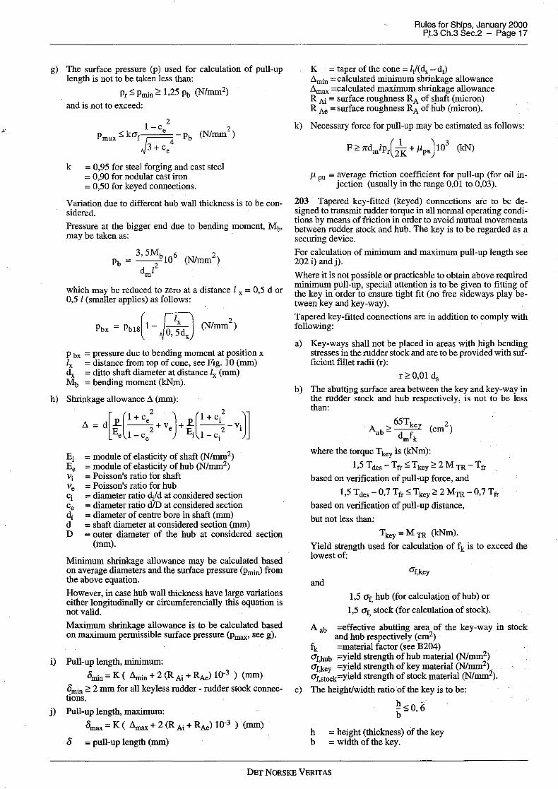
g) The surface pressure (p) used for calculation of pull-up length is not to be taken less than:
Pr$ Pmin ~ 1,25 Pb (N/mm2)
and is not to exceed:
1 - c 2 2 Pmax $ kaf e Pb (N/mm )
J3 + ce4
k = 0,95 for steel forging and cast steel = 0,90 for nodular cast iron = 0,50 for keyed connections.
Variation due to different hub wall thickness is to be considered.
Pressure at the bigger end due to bending moment, Mt, may be taken as:
3 5M 2 Pb = -'--b106 (N/mm )
d i2 m
which may be reduced to zero at a distance l x = 0,5 d or 0,5 l (smaller applies) as follows:
Pbx = Pb1s(1-Jo,?dJ (N/mm2
)
p bx ;:;; pressure due to bending moment at position x l, = distance from top of cone, see Fig. 10 (mm) d, = ditto shaft diameter at distance I, (mm) Mb = bending moment (kNm).
h) Shrinkage allowance A (mm):
A= d[f(1
+ ce: + ve)+ ~(l + ci:-vi)] e 1- Ce 1 1 - Ci
Ei = module of elasticity of shaft (N/mm2) Ee = module of elasticity of hub (N/mm2) vi = Poisson's ratio for shaft Ve =Poisson's ratio for hub ci = diameter ratio d/d at considered section Ce = diameter ratio d/D at considered section cl, = diameter of centre bore in shaft (mm) d = shaft diameter at considered section (mm) D = outer diameter of the hub at considered section
(mm).
Minimum shrinkage allowance may be calculated based on average diameters and the surface pressure (pminJ from the above equation.
However, in case hub wall thickness have large variations either longitudinally or circumferencially this equation is not valid.
Maximum shrinkage allowance is to be calculated based on maximum permissible surface pressure (pmax' see g).
i) Pull-up length, minimum:
°"1in = K ( Amin+ 2 (R Ai + RAel 10-3 ) (mm)
°"1in ~ 2 mm for all keyless rudder - rudder stock connections.
j) Pull-up length, maximum:
/)max= K ( Amax+ 2 (R Ai+ RAel 10-3 ) (mm)
I> = pull-up length (mm)
Rules for Ships, January 2000 P.t.3 Ch.3 Sec.2 - Page 17
K = taperof the cone= IJ(d, -cl,) Amin =calculated ntinimum shrinkage allowance .dmax ;;;calculated maximum shrinkage allowance R Ai = surface roughness RA of shaft (nticron) R Ae =surface roughness RA of hub (nticron).
k) Necessary force for pull-up may be estimated as follows:
F ~ n:dmlp,(2k + µpu)10
3 (kN)
µ pu = average friction coefficient for pull-up (for oil in-jection (usually in the range 0,01 to 0,03).
203 Tapered key-fitted (keyed) connections aie to be designed to transntit rudder torque in all normal operating conditions by means of friction in order to avoid mutual movements between rudder stock and hub. The key is to be regarded as a securing device.
For calculation of ntinimum and maximum pull-up length see 202 i) and j).
Where it is not possible or practicable to obtain above required ntinimum pull-up, special attention is to be given to fitting of the key in order to ensure tight fit (no free sideways play between key and key-way).
Tapered key-fitted connections are in addition to comply with following:
a) Key-ways shall not be placed in areas with high bending stresses in the rudder stock and are to be provided with sufficient fillet radii (r):
r~0,01 d,
b) The abutting surface area between the key and key-way in the rudder stock and hub respectively, is not to be less than:
65T Aab~~ (cm2)
dmfk
where the torque Tkey is (kNm):
1,5 Tdes -Tfr $ Tkey ~ 2 MTR -Tfr
based on verification of pull-up force, and
1,5 Tdes-0,7 Ttr $ Tkey ~ 2 MTR -0,7 Tfr
based on verification of pull-up distance,
but not less than:
T key = MTR (kNm).
Yield strength used for calculation of fk is to exceed the lowest of:
and CJ'f,key
1,5 O"f, hub (for calculation of hub) or
1,5 O"f, stock (for calculation of stock).
A ab =effective abutting area of the key-way in stock and hub respectively (cm2)
f k =material factor (see B204) O"f,hub =yield strength of hub material (N/mm2) O"f,key =yield strength of key material (N/mm2) O"f stock=yield strength of stock material (N/mm2).
c) The height/width ratio of the key is to be:
~<O i; b- ,
h =height (thickness) of the key b = width of the key.
DET NORSKE VERITAS

· Rules for Ships, January 2000 Pt.3 Ch.3 Sec.2 - Page 18
Where necessary tapered connections are to be provided with suitable means (e.g. oil grooves and bores to connect hydraulic injection oil pump) to facilitate dismantling of the hub.
204 Connection between rudder stock and splitted type of tiller or quadraot or rotor are to comply with 202 and 203 as applicable and with the following:
boss halves are to be joined by at least four bolts (two in each side) one or two keys cylindrical connections are to be duly secured with regard to axial loads.
205 Tiller or rotor joined to rudder stock by means of special locking assemblies, or by means of tapered connec.tion with intermediate sleeve, which traosmit torque aod/or axial forces by means of friction alone are to comply with the following:
a)
2,5 Tdes o; T1r<: 2,5 MTR
T fr = calculated friction torque.
T des and MTR, see 202.
b) When number of locking assemblies is less thao three, an arrangement is to be provided to limit drop of the rudder and stock in case of a slip in the friction connection.
Fig.10 Cone coupling
206 Where the rudder stock is connected to the rudder by horizontal flaoge coupling the following requirements are to be complied with:
a) At least 6 coupling bolts are to be used ..
b) The diameter of coupling bolts is not to be less thao:
ds = rule diameter of rudder stock at coupling flange in mm as given in 201
n = number of coupling bolts e = mean distance in mm from the centre of bolts to the
centre of the bolt system f ms =material factor (f1) for rudder stock f mb =material factor (f1) for bolts.
c) Nuts are to be securely fastened by split pins or other efficient means.
d) If the coupling is subjected to bending stresses, the meao distaoce a from the centre of the bolts to the longitudinal centre line of the coupling is not to be less thao O,q d,.
e) The width of material outside the bolt holes is not to be less than 0,67 db.
f) The thickness of coupling flaoges is not to be less thao the greater of:
db = bolt diameter, calculated for a number of bolts not exceeding 8
f mf = material factor (fi) for flange,
or
t = 70 Jf3Ms (mm) afmf
M6 = bending moment in kNm at coupling a =mean distance from centre of bolts to the longitudi-
nal centre line of the coupling, in mm d = diameter as built of rudder stock for stock flange,
breadth of rudder for rudder flaoge, both in mm f3 = factor to be taken from the following table:
d/a 0,8 0,9 1,0 1,1 1,2 1,3 1,4 1,5 1,6
/3 1,8 1,5 1,25 1,0 0,8 0,6 0,45 0,35 0,25
Ample fillet radius is to be in accordallce with recognised standards.
G 300 Rudder shaft
301 At the lower bearing, the rudder shaft diameter is not to be less thao:
(mm)
a+b c =
2 l, a aod b are given in Fig. 11 in m.
The diameter d1 below the coupling flaoge is to be 10% greater thao d1• If, however, the rudder shaft is protected by a corrosion-resistant composition above the upper bearing, c4- may be equal to d1.
302 The taper, nut, etc. at lower end of rudder shafts, is to be taken as for rudder stock given in 202 ..
303 The scantlings of the vertical coupling at the upper end of the rudder shaft are to be as required for horizontal rudder couplings in 206, inserting the shaft d1 instead of the stock diameter ds in the formula for bolt diameter.
DET NORSKE VERITAS

Lz
Fig.11 Rudder shaft
d,
TO. BE KEPT AS SMALL AS POSSIBLE
UPPER EDGE·OF THE LOWEST BOLT
LARGE FILLET
I Lz/2
I
CL
b
G 400 Bearings and pintles
401 The height of bearing surfaces is to be taken not greater than:
hb = 1,2 d,I (nun)
d5z = diameter in mm of rudder shaft or pintle measured on the outside of liners.
402 The bearing surface area is not to be less than:
As = hb d,1 hb and d,1 = as given in 401 P = calculated reaction force in kN at the bearing in
question Pm = maximum surface pressure as given in B303.
Rules for Ships, January 2000 Pt.3 Ch.3 Sec.2 - Page 19
If direct calculations of reaction forces are not carried out, P at various bearings may be taken as given in the following (note that values given for stem pintle or neck bearing in semi-spade rudders are minimum values):
a)
b)
For balanced rudder with heel support:
P = 0,6 FR (kN) at heel pintle bearing
P = 0, 7 FR (kN) at stem pintle or neck bearing
P = 0,1 FR (kN) at upper bearing.
For semi-spade rudder (The horn pintle bearing is assumed to be situated not more than 0,1 H above or below the centroid of the rudder):
P = 1, 1 FR (kN) at horn pintle bearing
P min = 0,4 FR (kN) at stern pintle or 0,3 FR (kN) at neck bearing
P = 0, 1 FR (kN) at upper bearingc ·
c) For spade rudder:
h1 + h2 P = --- (kN) at neck bearing
h2
h1 P = -FR (kN) at upper bearing
h2
h 1 = vertical distance from the centroid of rudder area to the middle of the neck bearing
h2 =vertical distance from the middle of the neck bearing to the middle of the upper bearing.
403 The diameter of pintles is not to be less than:
p as given in 402.
404 The thickness of any bushings in rudder bearings is not to be less than:
tv = 0, 32,/P (mm)
minimum 8 mm for steel and bronze,
maker1s specification for synthetic materials,
minimum 22 nun for Lignum Vitae,
other materials are to be especially considered.
P = as given in 402.
The bushing is to be effectively secured to the bearing. The thickness of bearing material outside of the bushing is not to be less than:
t = 2, 0 ff (nun) ~fl
P = as given in 402.
405 With metal bearings the clearance on the diameter is normally not to be less than:
0,001 db+ 1,0 (nun)
db=inner diameter in nun of the bushing.
If non-metallic bearing material is applied, the bearing clearance is to be specially determined considering the materials' swelling and thermal expansion properties. This clearance is not to be taken less than 1,5 nun on the bearing diameter.
DET NORSKE VERITAS

Rules for Ships, January 2000 Pt.3 Ch.3 Sec.2 - Page 20
For spade rudders with large bending moment and induced slope at the neck bearing the clearance should be related to the calculated angular deflection over the bearing.length.
Due attention should, however, be given to the manufacturer1s recommended clearance. For pressure lubricated bearings the clearance will be especially considered.
406 Pintles are to have a conical attachment to the gudgeons. The various dimensions (taper, nut, key) are to be as required for rudder stock in 202 and 203 inserting the pintle diameter clp instead of the stock diameter d, in the various formulae.
The bending moment, MB may be taken as pintle force P multiplied by the height from 1/3 of height of bearing to 112 of the length of cone and MTR may be taken as 0,00025 dbP.
db ; inner diameter of bushing (mm).
The length of pintle housing is not to be less than the pintle diameter and the thickness of material outside the bushing is not to be less than 0,25 db.
An effective sealing against sea water is to be provided at both ends of the cone.
H. Propeller Nozzles
H 100 General
101 The following requirements are applicable to fixed and steering nozzles of inner diameter 4 metres or less.
Guidance note: The requirements may also be applied for the initial design of nozzles with diameter exceeding 4 metres.
In that case the scantlings and arrangement should be specially considered with respect to exciting frequencies from the propeller.
---e-n-d---of---G-u-i-d-a-n-c-e---n-o-t-e---
H 200 Plating
201 The thickness of the nozzle shell plating in the propeller zone is not to be less than:
where:
N Ps ;
D ;
s
ka
t ; 10 + 3kas J~ (mm)
0,01 Ps D, need not be taken greater than 100 maximum continuous output (kW) delivered to the propeller inner diameter (m) of nozzle distance in m between ring webs, is not to be taken less than 0,35 metres in the formula aspect ratio correction as given in F201, to be applied when longitudinal stiffeners.
The thickness in zone I and IT is not to be less than 0,7 t and in zone Ill not less than 0,6 t, corrected for spacing s.
The propeller zone is to be taken minimum 0,25 b (where b ; length of nozzle). For steering nozzles the propeller zone is to cover the variations in propeller position.
On the outer side of the nozzle, zone II is to extend beyond the aftermost ring web.
202 The thickness of ring webs and fore and aft webs is not to be taken less than 0,6 t. They are to be increased in thickness in way of nozzle supports.
203 If the ship is reinforced according to an ice class notation, the part of the outer shell of the nozzle which is situated within the ice belt is to have a plate thickness not less than cor-
responding to the ice class requirement for-the after part of the ship.
Guidance note: In order to prevent corrosion and erosioil of the inner surlace of the nozzle, application of a corrosion resistant material in the propeller zone is recommended. All but welds should be ground smooth.
When a corrosion resistant material is used, the plate thickness may be reduced by 15%.
---e-n-d---of---G-u-i-d-a-n-c-e---n-o-t-e---
H 300 Nozzle ring stiffness
301 In order to obtain a satisfactory stiffness of the .nozzle ring the following requirement is to be fulfilled:
I ;
k ;
Im ;
b ;
D ;
v ;
n ;
Fig. 12
I;2,8kbD3y2 (cm4)
moment of inertia of nozzle section about the neutral axis parallel to centre line
28b
JDt:n<n+l)
mean thickness of nozzle inner and outer shell plating (mm), in propeller plane length of nozzle, see Fig. 12, in m as given in 201 maximum service speed (knots) number of ring webs.
zone II
b
zone m
propeller zone I zone
Section through nozzle ring
302 If the ship is reinforced according to an ice class notation the parameter V for the requirement in 301 is not to be taken less than:
V ; 14, 15, 16 and 17 knots for ice class 1C, 18, 1A and 1A*, respectively.
H 400 Welding
401 The inner shell plate is to be welded to the ring webs with double continuous fillet welding.
402 The outer shell plate is as far as possible to be welded continuously to the ring webs. Slot welding may be accepted on the following conditions:
If the web spacing s :;:; 350 mm all welds to outer plating may be slot welds. If the web spacing s > 350 mm at least two ring webs are to be welded continuously to the outer shell. A continuous weld according to Fig. 13 may be accepted.
403 Slot welds are to have a slot length l not less than 75 mm and a breadth equal to 2t (t ; nozzle shell plate thickness), maximum 30 mm. More narrow slots.may be applied where slots are completely filled by welding. The distance between slots (from centre to centre) is not to exceed 2
l, maximum 250 mm. The slot weld throat thickness is normally to be 0,7 t.
DET NORSKE VERITAS

H 500 Supports 501 The nozzle is to be supported by at least two supports. The web plates and shell plates of the support structure are to be in line with web plates in the nozzle.
6-10 mm
Fig. 13 Connection nozzle shell plate/ring web
I. Propeller Shaft Brackets
I 100 General 101 The following requirements are applicable to propeller shaft brackets having two struts to support the propeller tail shaft boss. The struts may be of solid or welded type.
102 The angle between the struts is not to be less than 50 degrees.
I 200 Arrangement
201 Solid struts are to be carried continuously through the shell plating and are to be given satisfactory support by the internal ship structure.
202 Welded struts may be welded to the shell plating. The shell plating is to be reinforced, and internal brackets in line with strut plating are to be fitted. If the struts are built with a longitudinal centre plate, this plate is to be carried continuously through the shell plating. The struts are to be well rounded at fore and aft end at the transition to the hull.
203 The propeller shaft boss is to have well rounded fore and aft brackets at the connection to the struts.
Regarding length of the propeller shaft boss it is referred to Pt.4 Ch.2 Sec.6 D800.
204 The strut structure inside the shell is to terminate within a compartment of limited volume to reduce the effect of flooding in case of damage.
I 300 Struts
301 Solid or built-up struts of propeller shaft brackets are to comply with the following requirements:
A = w =
h = d =
h=0,4d (mm)
A= 0,4 d2 (mm2)
W = 0,12 d3 (mm3)
area of strut section section modulus of section. W is to be calculated with reference to the neutral axis Y-Y as indicated on Fig. 14 the greatest thickness of the section Propeller shaft diameter in mm.
The diameter refers to shaft made of steel with a minimum specified tensile strength of 430 N/mm2.
Fig.14 Strut section
I 400 Welding
Rules for Ships, January 2000 pt.3 Ch.3 Sec.2 - Page 21
401 Welding between struts and hull and propeller shaft boss is to be made as full penetration welds.
402 For welded construction full details of the joints, welding procedure, filler metal and heat treatment after welding are to be specified on the plans.
I 500 Material
501 Regarding material of brackets reference is made to subsection B.
I 600 Testing
601 Ultrasonic and magnetic particle examination of the welds is to be carried out on the brackets and at the shell penetrations.
J. Steering Gears
J 100 Arrangement and performance
101 Unless expressly provided otherwise, every ship shall be provided with a main steering gear and an au xiii ary steering gear to the satisfaction of the requirements in the Rules. The main steering gear and the auxiliary steering gear shall be so arranged that the failure of one of them will not render the other one inoperative.
102 The main steering gear and rudder stock shall be:
a) of adequate strength and capable of steering the ship at maximum ahead service speed which shall be demonstrated
b) capable of putting the rudder over from 35° on one side to 35° on the other side with the ship at its deepest seagoing draught and running ahead at maximum ahead service speed and, under the same conditions, from 35° on either side to 30° on the other side in not more than 28 seconds (20 seconds for class notation Tug or Supply Vessel, see Pt.5 Ch.7 Sec.2 and Sec.3 and ice classes: ICE 05-15, POLAR 10-30 and 15 seconds for Icebreaker, see Pt.5 Ch.I Sec.4)
c) operated by power where necessary to meet the requirements in b) and in any case when the rules require a rudder stock of over 120 mm diameter in way of the tiller, excluding strengthening for navigation in ice
d) so designed that they will not be damaged at maximum astern speed.
103 The auxiliary steering gear shall be:
a) of adequate strength and capable of steering the ship at navigable speed and of being brought speedily into action in an emergency
b) capable of putting the rudder over from 15° on one side to 15° on the other side in not more than 60 seconds with the ship at its deepest seagoing draught and running ahead at one half of the maximum ahead service speed or 7 knots, whichever is the greater
DET NORSKE VERITAS

- Rules for Ships, January 2000 Pt3 Ch,3 Sec,2 - Page 22
c) operated by power where necessary to meet the requirements in b) and in any case when the rules require a rudder stock of over 230 mm diameter in way of the tiller, excluding strengthening for navigation in ice.
Guidance note:
Manually operated gears are only acceptable when the operation does not require an effort exceeding 160 N under nonnal conditions.
---e-n-d---of---G-u-i-d-a-n-c-e---n-o-t-e---
104 Where the main steering gear compriSes two or more identical power units, an auxiliary steering gear need not be fitted, provided that:
a) in a passenger ship, the main steering gear is capable of operating the rudder as required in 102 b) while any one of the power units is out of operation
b) in a cargo ship, the main steering gear is capable of operating the rudder as required in 102 b) while operating with all power units
c) the main steering gear is so arranged that after a single failure in its piping system or in one of the power units the defect can be isolated so that steering capability can be maintained or speedily regained,
Auxiliary gear need not be fitted when the ship is provided with:
two rudders, each with its own steering gear and capable of steering the vessel with any one of the rudders out of operation, or fitted with an approved alternative means of steering, such as azimuth thruster, capable of steering the vessel with the rudder out of operation and provided with approved remote control from the bridge or for non-propelled vessels.
105 In every oil carrier, chemical carrier or liquefied gas carrier of 10 000 tons gross tonnage and upwards and in every other ship of 70 000 tons gross tonnage and upwards, the main steering gear shall comprise two or more identical power units complying with the requirements in 104,
106 Steering gears for over-balanced rudders, which are subject to Cl08, are to be designed to prevent a sudden turn of rudder in case ofloss of steering gear torque due to a single failure in the steering gear power or control systems, inclusive failure in power supply,
107 Main and auxiliary steering gear power units shall be:
a) arranged to restart automatically when power is restored after a power failure
b) capable of being brought into operation from a position on the navigating bridge, In the .event of a power failure to any one of the steering gear power units, an audible and visual alarm shall be given on the navigating bridge
c) arranged so that transfer between .units can be readily effected,
108 Where the steering gear is so arranged that more than one system (either power or control) can be simultaneously operated, the risk of hydraulic locking caused by a single failure is tO be considered.
Guidance note: The "hydraulic locking" is a phenomenon which may be experienced when two hydraulic systems (usually identical) works against each other.
---e-n-d--~of---G-u-i-d-a-n-c-e---n-o-t-e---
109 Steering gears are to be mounted on substantial seatings, which will effectively transmit the rudder torque to the hull structure, Deck plating under rudder carrier is to be of substantial thickness. Prior to installation all welding Ilear the seatings have to be completed. The deck underneath is to be efficiently supported to take the weight of steering gear and rudder with rudder stock
110 Suitable stopping arrangements are to be provided for the rudder, The stoppers may be an integral part of the rudder actuator. Power cut-out to the actuator is to operate at a smaller angle of helm than those for the rudder, and are to be synchronised with the gear itself and not with the control system,
111 Steering gears, other than of the hydraulic type, will be accepted provided the standards are considered equivalent to the requirements of this section.
112 The steering gear compartment shall be:
a) readily accessible and, as far as practicable, separated from machinery spaces
b) provided with suitable arrangements to ensure working access to steering gear machinery and controls,
These arrangements shall include handrails and gratings or other non-slip surfaces to ensure suitable working conditions in the event of hydraulic fluid leakage,
(SOLAS reg, II-1/29.13)
113 Electrical power units are to be placed on elevated platforms in order to avoid water splash.
114 A means of communication according to PtA Ch,9 Sec-2 B 10 I is to be provided,
J 200 Power actuating systen1, general requirements
201 Rudder actuators other than those covered by the IMO "Guidelines'' for non-duplicated rudder actuators, see Appendix A, are to be designed in accordance with the relevant requirements of PtA Ch3 for Class I pressure vessels (notwithstanding any exemptions for hydraulic cylinders),
202 Accumulators, if fitted, are to comply with the rele.vant requirements of Pt A Ch3,
203 The welding details and welding procedures are to be approved, All welded joints within the pressure boundary of a rudder actuator or connecting parts transmitting mechanical loads are to be full penetration type or of equivalent strength,
204 The construction is to be such as to minimise local concentrations of stress.
205 The design pressure for calculations to detennine the scantlings of piping and other steering gear components subjected to internal hydraulic pressure shall be at least 1,25 times the maximum working pressure under the operational conditions specified in 102 b) taking into account any pressure which may exist in the low pressure side of the system. Fatigue criteria may be applied for the design of piping and components, taking into account pulsating pressures due to dynamic loads (see Appendix A),
206 The permissible primary general membrane stress subject to 205 is not to exceed the lower of the following values:
(Jb (JV - or --"'" A B
ab specified minimum tensile strength of material at ambient temperature
O'y = specified minimum yield stress or 0,2 per cent proof stress of the material, at ambient temperature.
DET NORSKE VERITAS

A and B are given by the following table:
Table Jl Permissible primary membrane stress Steel Cast steel Nodular cast iron
A 3,5 4 5 B 1,7 2 3
207 Special consideration is to be given to the suitability of any essential component which is not duplicated. Any such essential component shall, where appropriate, utilise anti-friction bearings such as ball bearings, roller bearings or sleeve bearings which shall be permanently lubricated or provided with lubrication fittings.
208 All steering gear components transmitting mechanical forces to the rudder stock, which are not protected against overload by structural rudder stops or mechanical buffers, are to have a strength at least equivalent to that of the rule rudder stock in way of the tiller.
209 Oil seals between non-moving parts, forming part of the external pressure boundary, should be of the metal upon metal type or of an equivalent type.
210 Oil seals between moving parts, forming part of the external pressure boundary, should be duplicated, so that the failure of one seal does not render the actuator inoperative. Alternative arrangements providing equivalent protection against leakage may be accepted.
211 Hydraulic power operated steering gears are to be provided with:
a) arrangements to maintain the cleanliness of the hydraulic fluid taking into consideration the type and design of the hydraulic system
b) a fixed storage tank having sufficient capacity to recharge at least one power actuating system including the reservoir, where the main steering gear is required to be power operated. The storage tank is to be permanently connected by piping in such a manner that the hydraulic systems can be readily recharged from a position within the steering gear compartment and provided with a contents gauge.
212 Hydraulic power supply for steering gear is not to be used for other purposes.
J 300 Piping systems, relief valve arrangements
301 Piping, joints, valves, flanges and other fittings are to comply with the requirements of Pt.4 Ch. I. Power piping is to comply with requirements to class I pipes. The design pressure is to be in accordance with 205.
302 For all vessels with non-duplicated actuators, isolating valves, directly fitted on the actuator, are to be provided at the connection of pipes to the actuator.
303 Main and auxiliary steering gear are to be provided with separate hydraulic power supply pipes. When main steering gear is arranged in accordance with 104, each hydraulic power unit is to be provided with separate power pipes. Interconnections between power pipes are to be provided with qnick operating isolating valves.
304 Arrangements for bleeding air from the hydraulic system are to be provided, where necessary.
305 Relief valves are to be fitted to any part of the hydraulic system which can be isolated and in which pressure can be generated from the power source or from external forces. The setting of the relief valves is not to exceed the design pressure. The valves are to be of adequate size and so arranged as to avoid an undue rise in pressure above the design pressure.
306 Relief valves for protecting any part of the hydraulic system which can be isolated, as required in 305 are to comply with the following:
Rules for Ships, January 2000 Pt.3 Ch.3 Sec.2 - Page 23
a) The setting pressure is not to be-less than 1,25 times the maximum working pressure.
b) The minimum discharge capa<eity of the relief valve(s) is not to be less than 110 per cent of the total capacity of the pumps which can deliver through it (them). Under such conditions the rise in pressure is not to exceed 10 per cent of the setting pressure. In this regard, due consideration is to be given to extreme foreseen ambient conditions in respect of oil viscosity.
307 Flexible hoses of approved type may be installed between two points where flexibility is required but are not to be subjected to torsional deflection (twisting) under normal operating conditions. In general, the hose should be liµrited to the length necessary to provide for flexibility and for proper operation of machinery.
308 Hoses are to be high pressure hydraulic hoses according to recognised standards and snitable for the fluids, pressures, temperatures and ambient conditions in question. For detailed requirements for construction and testing of flexible hoses, see Pt.4 Ch. I Sec.6 D.
J 400 Rudder actuator
401 The actuator housing may be cast or welded construction. Parts subjected to internal pressure are to satisfy the design requirements in 200.
402 The structural design is to be chosen with due respect to transmission of reaction forces to the seatings.
403 The rudder carrier, or in case of an integral unit, the rudder actuator and its fastening to foundations, is to be able to take reaction forces due to bending set up in rudder stock. Side chocks may be required in addition to fitted bolts.
404 The permissible equivalent stress in tiller arms, rotor vanes, stoppers, piston rods, rams, guides and other similar parts, where calculations are based on the rule mdder torque, MTR is:
a.$ 118fi( 1 - ';:') (N/mm2
)
and where calculated at the design pressure:
a.$ 150f1( 1- ';;') (N/mm2
)
For certain parts, which are not subject to reversed load, permissible stress at the design pressure may be increased to:
a.$ 185f1( 1 - ';;') (N/mm2
)
Permissible bending stress in rotor vanes calculated at design pressure is:
( ()"fit) 2 (J"b s 1, 5cr AB 1 - (J"f (N/mm )
Fillets are to be smooth and well rounded to give reasonable low stress concentrations (geometrical stress concentration (factor) Sl,5).
Relevant stresses due to pretensioning of bolts, or shrink fitting of hubs, etc. are to be duly considered.
O"e = permissible von Mises equivalent stress in N/mm2
O"f = yield strength of the material in N/mm2 (see B200) f 1 = material factor, see B204 . O'fit = static stress di.ie to pretension or shrinkage in N/mm2.
Tangential shrink fitting stress at the hub surface may be taken as follows:
DET NORSKE VERITAS

· Rules for Ships, January 2000 Pt.3 Ch.3 Sec.2 - Page 24
(l+ce
2 J 2 afit = p --2 - I (N/mm )
1-ce
ab = permissible bending stress in N/mm2
a a smaller of the ; or ~ in 206
p actual pressure due to shrinkage in N/mm2 (see G200).
Average hub thickness in way of vanes shall normally not be less than 70% of required vane root thickness.
Design torqueT des of a rudder actuator for calculation of rudder stock connection is to be taken as:
T pnAlcos<!> 10-3 (kNm) des = cose
T des is not to exceed:
p steering gear design pressure (MPa) n = number of active pistons or vanes A = piston or vane (projected) area (mm2) l torque arm (m), see Fig. 15 e = rudder angle
= O'C for rotary vane and linked cylinder type actuator = maximum permissible rudder angle (normally 35') for
ram type actuator <P as defined in Fig. 15
= O' for ram and rotary vane type actuator d = rudder stock minimum diameter below tiller or rotor
(mm) kb bending moment factor, see G201.
The shearing force based on rule rudder torque in each of the arms or vanes may be expressed as:
M p = TR (kN)
A nl
Corresponding bending moment at the root of arms or vanes may be expressed as:
The effective shear area of arms or vanes is, however, not to be less than (greater of the values applies):
d 3 A = _s_o_ or~ (mm2)
A 5000nl 50f l
= length of tiller arm measured from centre of rudder stock to point of action of driving force in m
n = number of arms or vanes (not to be taken greater than 3)
d = diameter of tiller boss, in m d so = rule diameter of rudder stock at tiller, see G200, in mm MTR =rule rudder torque, see D200.
The value of l will depend on the design of the tiller or rotor and also on the angle of helm as illustrated in Fig. 15.
405 Hydraulic cylinder type actuators are to comply with requirements for buckling strength given in Pt.4 Ch. I.
1:
Fig.15 Steering gears
DET NORSKE VERITAS
Pu VP/cos9"Pa
a) ram type
¢
c) linked <:ylinder type

J 500 Steering gear control and monitoring systems, general requirements
501 For instrumentation and automation, including computer based control and monitoring, the requirements in this chapter are additional to those given in Pt.4 Ch.5.
502 Steering gear control system is the equipment by which orders are transmitted from the navigation bridge to the steering gear power units. Steering gear control systems comprise transmitters, receivers, hydraulic control pumps and their associated motors, motor controllers, piping and cables.
503 Steering gear control shall be provided:
a) for the main steering gear, both on the navigating bridge and in the steering gear compartment
b) where the main steering gear is arranged in accordance with 104 by two independent control systems, both operable from the navigating bridge. This does not require duplication of the steering wheel or steering lever. Where the control system consists of an hydraulic telemotor, a second independent system operable from the bridge need not be fitted, except in an oil carrier, chemical carrier or liquefied gas carrier of 10 000 tons gross and upwards
c) for the auxiliary steering gear, in the steering gear compartment and, if power operated, it shall also be operable from the navigating bridge and shall be independent of the control system for the main steering gear.
504 Any main and auxiliary steering gear control system operable from the navigating bridge shall comply with the following:
a) If electric, it shall be served by its own separate circuit supplied from a steering gear power circuit from a point within the steering gear compartmen~ or directly from switchboard busbars supplying that steering gear power circuit at a point on the switchboard adjacent to the supply to the steering gear power circuit.
b) Means shall be provided in the steering gear compartment for disconnecting any control system operable from the navigating bridge from the steering gear it serves.
c) The system shall be capable of being brought into operation from a position on the navigating bridge.
d) In the event of a failure of electrical power supply to the control system, an audible and visual alarm shall be given on the navigating bridge.
e) Short circuit protection only shall be provided for steering gear control supply circuits.
505 The electric power circuits and the steering gear control systems with their associated components, cables and pipes are to be separated as far as is practicable throughout their length.
506 When two or more exclusive electric control systems are used, these are to be kept separated with separate cables and are not to be located in the same enclosure. Regarding arrangements in steering stands, this requirement may be waived, provided the systems are securely installed and separated as far as practicable.
Steering order devices for exclusive electric control systems may be operated by the same wheel or lever shaft.
Steering mode and steering station selectors for exclusive electric systems may also be operated by the same shaf' provided the arrangement is of reliable construction.
507 If additional steering stations are arranged with control circuits branched off from a main steering station, it is to be possible to disconnect each such circuit by a multipole switch on the main steering station.
Rules for Ships, January 2000 Pt3 Ch.3 Sec.2 - Page 25
J 600 Control gear for steering motors
601 Steering gear motors are to be provided with control gear according to requirements giv~n in Pt.4 Ch.4 Sec.3 G 100. The control gear is, however, not to have overcurrent or other overload releases.
602 Steering gear motors are to be remote controlled from the bridge and local controlled from the steering gear compartment. When remote control is arranged from two or more positions, the arrangement is to be such that the motor can be started independently from any of these positions.
603 The control circuit of each steering gear motor is to be such that a motor in operation will restart automatically upon restoration of voltage after a power failure.
J 700 Indications and alarms
701 Alarm and indication requirements are specified in Table J2.
702 All alarms associated with steering gear faults are to be indicated on the navigating bridge and in machinery space where they can be readily observed.
703 The rudder angle indicating system is to be independent of any control system and so arranged that a single failure in power supply or anywhere in the indication system does not cause loss of rudder angle indication on the bridge.
704 Where hydraulic locking, caused by a single failure, may lead to loss of steering, an alarm, which identifies the failed system, is to be provided.
Guidance note: This alarm should be activated when there is disagreement between the given order versus control system output/execution. For instance when:
position of the variable displacement pump control system does not correspond with given order; or incorrect position of 3-way full flow valve or similar in constant delivery pump system is detected.
---e-n-d---of---0-u-i-d-a-n-c-e---n-o-t-e---
J 800 Power supply and distribution
801 Power supply is to be arranged with redundancy. For ships where main source of electric power is arranged without redundancy, the steering gear is to be arranged in such a way that steering from the bridge will be possible also after loss of main electric power, e.g. by means of direct hand-hydraulic steering.
802 At least two exclusive circuits are to be provided for each electric or electrohydraulic steering gear arrangement comprising one or more power units.
803 Each of the exclusive circuits is to be fed from the main switchboard, however, one circuit may pass through the emergency switchboard.
804 One of these circuits may supply an associated auxiliary electric or electrohydraulic steering gear.
805 Each of these circuits is to have adequate capacity to supply all motors which may be connected and operated simultaneously.
806 In ships ofless than 1600 gross tonnage, if provided with an auxiliary steering gear independent of electrical power supply, the main steering gear may be fed by one circuit from the main switchboard. ·
807 Where the rudderstock is required to be over 230 mm diameter (excluding ice strengthening) in way of the tiller, an alternative power supply shall be provided automatically within 45 seconds, either from the emergency source of electrical
DET NORSKE VERITAS

· Rules for Ships, January 2000 Pt.3 Ch.3 Sec.2 - Page 26
power or from an independent source of power located in the steering gear compartment.
Table J2 Monitoring requirements for steering gear -Indication
Item Alarm subject position
Remarks
Rudder position Rudder angle Bridge and steering gear compartment
Steering gear power units Power failure Phase failure Running Bridge and machinery Motor overload space
Steering gear Hydraulic lock Shall identify failed sys-tern
Steering gear control sys- Power failure Ready for operation Dis- Bridge Low pressure alarm is re-tern connection of bridge con- quired when contrcil sys-
trol system tern is not integrated in the main system
Steering gear hydraulic Low level Low level alarm indication system oil tanks (each - in- is not to be combined with elusive steering control other alarms on the bridge system tanks) 1)
Storage tank Oil level Content gauge on the tank
Auto pilot Failure Running Bridge Alarm on bridge only 1) Low level alann in separate steering gear control system oil tanks may be substituted by low pressure alarm. It is provided that each of the systems is able
to control the main steering gear alone, and that oil leakage in one system has no effect on the other one
J 900 Emergency power supply
901 Where the rudder stock is required to be over 230 mm diameter in way of the tiller, excluding strengthening for navigation in ice, an alternative power supply, sufficient at least to supply the steering gear power unit which complies with the requirements in 103 and also its associated control system and the rudder angle indicator, shall be provided automatically, within 45 seconds, either from the emergency source of electrical power or from an independent source of power located in the steering gear compartment. This independent source of power shall be used only for this purpose.
902 In every ship of 10 000 gross tonnage and upwards, the alternative power supply shall have a capacity for at least 30 minutes of continuous operation and in any other ship for at least 10 minutes.
903 Where the alternative power source is a generator, or an engine driven pump, starting arrangements are to comply with the requirements relating to the starting arrangements of emergency generators.
J 1000 Operating instructions 1001 Appropriate operating instructions with a block diagram showing the change-over procedures for steering gear control systems and steering gear actuating systems are to be permanently displayed in the wheelhouse and in the steering gear compartment.
1002 Where the system failure alarms according to 704 are provided, appropriate instructions are to be given to shut down the failed system.
J 1100 Additional requirements for oil carriers, chemical carriers and liquefied gas carriers of 10 000 tons gross and upwards 1101 Every oil carrier, chemical carrier or liquefied gas carrier of 10 000 tons gross and upwards are, subject to 1102 to comply with the following:
a) The main steering gear is to be so arranged that in the event of loss of steering capability due to a single failure in any part of one of the power actuating systems of the main steering gear, excluding the tiller, quadrant or components serving the same purpose, or seizure of the rudder actuators, steering capability is to be regained in not more than 45 seconds after the loss of one power actuating system.
b) The main steering gear is to comprise either:
two independent and separate power actuating systems, each capable of meeting the requirements in 102 b), or at least two identical power actuating systems which, acting simultaneously in normal operation, are to be capable of meeting the requirements in 102 b ). Wbere necessary to comply with this requirement, inter-connection of hydraulic power actuating systems is to be provided. Loss of hydraulic fluid from one system is to be capable of being detected and the defective system automatically isolated so that the other actuating system or systems are to remain fully operational.
c) Steering gears other than of the hydraulic type are to achieve equivalent standards.
1102 For oil carriers, chemical carriers or liquefied gas carriers of 10 000 tons gross and upwards, but ofless than 100 000 tonnes deadweight, solutions other than those set out in I IOI, which need not apply the single failure criterion to the rudder actuator or actuators, may be permitted provided that an equivalent safety standard is achieved and that:
a) following loss of steering capability due to a single failure of any part of the piping system or in one of the power units, steering capability is to be regained within 45 seconds, and
b) where the steering gear includes only a single rudder actuator, special consideration is given to stress analysis for the design including fatigue analysis and fracture mechanics analysis, as appropriate, to the material used, to the installation of sealing arrangements and to testing and inspection and to the provision of effective maintenance. In consideration of the foregoing, regard will be given to the IMO «Guidelines» for non-duplicated rudder actuators, given in Appendix A.
K. Testing -.
K 100 Sternframes
101 Built stemframes with closed sections are to be pressure tested on completion.
DET NORSKE VERITAS

K 200 Rudders and rudder stock connections
201 Rudders are to be hydraulically tested with an internal pressure:
Po = 10 T (kN/m2), minimum 50 kN/m2
Upon special agreement with the Society the hydraulic test may be replaced by an air tightness test in compliance with Ch.1 Sec.ID.
202 Contact area of conical connections is to be (minimum 70%) verified by means of paint test (e.g. tool-maker blue) in presence of the surveyor.
203 Test pull-up followed by control of contact area may be required before final assembly for conical keyless connections intended for injection fitting, if calculations are considered inaccurate due to a non-symmetric design or other relevant reasons. Pull-up length during test pull-up is not to be less than final pull-up length.
K 300 Steering gears
301 The requirements of the rules relating to the testing of class I pressure vessels, piping, and related fittings apply. Test pressure for internal pressure testing is to be 1,5 times the design pressure.
302 After installation on board the vessel the steering gear is to be subjected to the required hydrostatic and running tests.
303 On double rudder installation where the two units are synchronised by mechanical means, mutual adjustment is to be tested.
304 For testing and certification of hydraulic, electrical and instrumentation and/or automation parts and systems, see Pt.4 Ch.I, Pt.4 Ch.4 and Pt.4 Ch.5, respectively.
305 Each type of power unit pump is to be subjected to a type test. The type test shall be for a duration of nut less than 100 hours, the test arrangements are to be such that the pump may run in idling conditions, and at maximum delivery capacity at maximum working pressure. During the test, idling periods are to be alternated with periods at maximum delivery capacity at maximum working pressure. The passage from one condition to another should occur at least as quickly as on board. During the whole test no abnormal heating, excessive vibration or other irregularities are permitted. After the test, the pump is to be dismantled and inspected. Type tests may be waived for a power unit which has been proven to be reliable in marine service.
K 400 Trials
401 The steering gear is to be tried out on the trial trip in order to demonstrate to the surveyor's satisfaction that the requirements of the rules have been met. (The design requirement given in Jl 02 d) need not be proved by trials at maximum astern speed and maximum rudder angles.) The trial is to include the operation of the following:
a) Trial conditions:
loaded on summer load waterline running ahead at maximum service speed corresponding to maximum nominal shaft RPM and maximum continuous rating (MCR) of the main engine(s) and if equipped with controllable pitch propeller(s), the pro-
Rules for Ships, January 2000 Pt.3 Ch.3 Sec.2 - Page 27
peller pitch is to be at the maximum design pitch corresponding to the nominal shaft RPM and MCR of the main engine(s).
If the vessel cannot be tested On summer load waterline, alternative trial conditions may be specially considered. See 402 and 403.
al) Main steering gear trial:
turning the rudder over from 35° on one side to 35° on the other side and vice versa from 35° on either side to 30° on the other sides respectively within required time as given in Jl 02, or if class notation Tug, Supply Vessel, or Ice Classes ICE 05-15 or POLAR 10-30, or Icebreaker in the respective rule sections.
Where main steering gear comprises two or more identical power units, the steering gear is to be tested with each power unit individually and all together, provided these are intended for simultaneous running. For capacity versus number of power units in operation, see Jl 04.
a2) Auxiliary steering gear trial:
turning the rudder over from 15° on one side to 15° on the other side in not more than 60 seconds with the ship on summer load waterline and running ahead at one half of the maximum ahead service speed or 7 knots, whichever is the greater.
b) the steering gear power units, including transfer between steering gear power units
c) the isolation of one power actuating system, checking the time for regaining steering capability
d) the hydraulic fluid recharging system
e) the emergency power supply required in J900
f) the steering gear controls, including transfer of control and local control
g) the means of communication between the steering gear compartment and the wheelhouse, also the engine room, if applicable
h) the alarms and indicators
i) where steering gear is designed to avoid hydraulic locking this feature shall be demonstrated.
Test items d), g) and h) may be effected at the dockside.
402 When performance test is carried out with reduced draught with partly submerged rudder, calculations showing corresponding rudder force and torque for the trials are to be submitted on request.
403 Ships fitted with semi-spade rudders are normally to be tested with the rudders completely submerged. However, when satisfactory results are proved by sister ships, tests according to 402 with partly submerged rudder may be accepted. Calculations of the expected rudder force and torque for the trials are to be submitted. If test results for sisterships are not available, steering gear test with rudder partly submerged may be accepted upon special consideration in each case.
DET NORSKE VERITAS

Rules for Ships, January 2000 Pt.3 Ch.3 Sec.3 - Page 28
SECTION3 ANCHORING AND MOORING EQUIPMENT
A. General
A 100 Introduction 101 The requirements in this section apply to equipment and installation for anchoring and mooring.
102 Towlines and mooring lines are not subject to classification. Lengths and breaking strength are, however, given in the equipment tables as guidance. If certification of materials is needed voluntarily, it shall be done in accordance with 204.
A 200 Documentation 201 The following plans and particulars are to be submitted for approval:
equipment number calculations equipment (list) including type of anchor, grade of anchor chain, type and breaking load of steel and fibre ropes anchor design if different from standard or previously approved anchor types. Material specification windlass design. Material specifications for cable lifters, shafts, couplings and brakes chain stopper design. Material specification.
202 The following plans and particulars are to be submitted for information:
- arrangement of deck equipment.
203 For barges the towline fastening arrangement and details, stating towing force is to be submitted for approval.
204 Det Norske Veritas Product Certificate (NV) (for materials, ISO 10474: Type 3.1 C) will be required for the following items:
anchor and anchor shackle anchor chain cable and accessories (shackles, swivels, etc.) windlass cable lifter winch drum and drum flanges shafts for cable lifter and/or drum pawl wheel, stopper and couplings gear shafts and wheels (W) windlass/winch frame work (W) brake components chain stopper steel wire ropes (W) fibre ropes (W).
For items above marked with (W), work's certificate (for materials, ISO 10474: Type 3.1 B) from approved manufacturer will normally be accepted.
A 300 Assnmptions 301 The anchoring equipment required is the minimum considered necessary for temporary mooring of a vessel in moderate sea conditions when the vessel is awaiting berth, tide, etc. The equipment is therefore not designed to hold a vessel off fully exposed coasts in rough weather or for frequent anchoring operations in open sea. In such conditions the loads on the anchoring equipment will increase to such a degree that its components may be damaged or lost owing to the high energy forces generated.
Guidance note: If the intended service of the vessel is such that frequent anchoring in open sea is expected, it is advised that the size of anchors and chains is increased above the rule requirements, taking into
account the dynamic forces imposed by the vessel moving in heavy seas. The Equipment Numeral (EN) formula for required anchoring equipment is based on an assumed current speed of 2,5 mis, wind speed of 25 mis and a scope of chain cable between 6 and 10, the scope being the ratio between length of chain paid out and water depth.
---e-n-d---of---G-u-i-d-a-n-c-e---n-o-t-e---
302 The anchoring equipment required by the Rules· is designed to hold a vessel in good holding ground in conditions such as to avoid dragging of the anchor. In poor holding ground the holding power of the anchors will be significantly reduced.
303 It is assumed that under normal circumstances the vessel will use only one bower anchor and chain cable at a time.
B. Structural Arrangement for Anchoring Equipment
B 100 General
101 The anchors are normally to be housed in hawse pipes of suitable size and form to prevent movement of anchor and chain due to wave action.
The arrangements are to provide an easy lead of the chain cable from the windlass to the anchors. Upon release of the brake, the anchor is immediately to start falling by its own wt!ight. At the upper and lower ends of hawse pipes, there are to be chafing lips. The radius of curvature is to be such that at least 3 links of chain will bear simultaneously on the rounded parts at the upper and lower ends of the hawse pipes in those areas where the chain cable is supported during paying out and hoisting and when the vessel is laying at anchor. Alternatively, roller fairleads of suitable design may be fitted.
Where hawse pipes are not fitted alternative arrangements will be specially considered.
102 The shell plating in way of the hawse pipes is to be increased in thickness and the framing reinforced as necessary to ensure a rigid fastening of the hawse pipes to the hull.
103 Ships provided with a bulbous bow, and where it is not possible to obtain ample clearance between shell plating and anchors during anchor handling, local reinforcements of bulbous bow are to be provided as necessary.
104 The chain locker is to have adequate capacity and a suitable form to provide a proper stowage of the chain cable, and an easy direct lead for the cable into the chain pipes, when the cable is fully stowed. Port and starboard cables are to have separate spaces. If 3 bower anchors and 3 hawse pipes are used, there are to be 3 separate spaces. The chain locker boundaries and access openings are to be watertight. Provisions are to be made to minimise the probability of chain locker being flooded in bad weather. Adequate drainage facilities of the chain locker are to be adopted.
Provisions are to be made for securing the inboard ends of chain to the structure. This attachment is to be able to withstand a force of not less than 15% nor more than 30% of the minimum breaking strength of the chain cable. The fastening of the chain to the ship is to be made in such a way that in case of emergency when anchor and chain have to be sacrificed, the chain can be readily made to slip from au accessible position outside the chain locker.
DET NORSKE VERITAS

Rules for Ships, January 2000 Pt.3 Ch.3 Sec.3 - Page 29
105 The windlass and chain stoppers are to be efficiently hi bedded to the deck. The deck plating in way of windlass and chainstopper is to be increased in thickness and supported by pillars carried down to rigid structures. See Sec.5 B.
= height in m on the centre line of each tier of houses having a breadth greater than B/4. For the lowest tier, hi is to be measured at centre line from the upper deck, or from a notional deck line where there is local discontinuit)' in the upper deck · ··
C. Equipment Specification
C 100 Equipment number
101 The equipment number is given by the formula:
EN= ~213 + 2 B H + 0,1 A
H = effective height in m from the summer load waterline to the top of the uppermost deckhouse, to be measured as follows:
a :: distance in m from summer load waterline amidships to the upper deck at side
Table Cl Equipment table, general
A area in m2 in profile view of the hull, superstructures and houses above the summer load waterline, which is within L of the ship. Houses of breadth less than B/4 are to be disregarded.
In the calculation of L hi and A sheer and trim are to be ignored.
Windscreens or bulwarks more than 1,5 min height are to be regarded as parts of superstructures and of houses when determining H and A. The total area of the mentioned items measured from the deck, is to be included.
The area of hatch coaruings more than 1,5 m in height above deck at side is to be included in A.
102 For a barge rigidly connected to a push-tug the equipment number is to be calculated for the combination regarded as one unit.
Stockless bower Stud-link chain cables Towline Mooring lines 1 J anchors (guidance) (guidance)
Equip- Mass Total Diameter and steel grade Steel or fibre ropes Steel or fibre ropes Equipment ment per an- length number letter Number char NV NV NV Mini- Minimum Length Minimum
Kl K2 K3 mum breaking Number of each breaking length strength strength
kg m mm mm mm m kN m kN
30-49 "o 2 120 192,5 12,5 170 88,5 2 80 32 50-69 a 2 180 220 14 12,5 180 98,0 3 80 34 70-89 b 2 240 220 16 14 180 98,0 3 100 37 90-109 c 2 300 247,5 17,5 16 180 98.0 3 110 39 110-129 d 2 360 247,5 19 17,5 180 98 3 110 44 130-149 e 2 420 275 20,5 17,5 180 98 3 120 49 150-174 f 2 480 275 22 19 180 98 3 120 54 175-204 g 2 570 302,5 24 20,5 180 112 3 120 59 205-239 h 2 660 302,5 26 22 20,5 180 129 4 120 64 240-279 i 2 780 330 28 24 22 180 150 4 120 69 280-319 j 2 900 357,5 30 26 24 180 174 4 140 74 320-359 k 2 1020 57,5 32 28 24 180 207 4 140 78 360-399 1 2 1140 385 34 30 26 180 224 4 140 88 400-449 m 2 1290 385 36 32 28 180 250 4 140 98 450-499 n 2 1440 412,5 38 34 30 180 277 4 40 108 500-549 0 2 1590 412,5 40 34 30 190 306 4 160 123 55Cl-599 p 2 1740 440 42 36 32 190 338 4 160 132 600-659 q 2 1920 440 44 38 34 190 371 4 160 147 660-719 r 2 2100 440 46 40 36 190 406 4 160 157 720-779 s 2 2280 467,5 48 42 36 190 441 4 170 172 780-839 t 2 2460 467,5 50 44 38 190 480 4 170 186 840-909 u 2 2640 467,5 52 46 40 190 518 4 170 201 910-979 v 2 2850 495 54 48 42 190 559 4 170 216 980-1059 w 2 3060 495 56 50 44 200 603 4 180 230 1060-1139 x 2 3300 495 58 50 46 200 647 4 180 250 1140-1219 y 2 3540 522,5 60 52 46 200 691 4 180 270 1220-1299 z 2 3780 522,5 62 54 48 200 738 4 180 284 1300-1389 A 2 4050 522,5 64 56 50 200 786 4 180 309
1390-1479 B 2 4320 550 66 58 50 200 836 4 180 324 1480-1569 c 2 4590 550 68 60 52 220 888 5 190 324 157Cl-1669 D 2 4890 550 70 62 54 220 941 5 190 333
1670-1789 E 2 5250 577,5 73 64 56 220 1024 5 190 353 1790-1929 F 2 5610 577,5 76 66 58 220 1109 5 190 378 1930-2079 G 2 6000 577,5 78 68 60 220 1168 5 190 402
2080-2229 H 2 6450 605 81 70 62 240 1259 5 200 422 2230-2379 I 2 6900 605 84 73 64 240 1356 5 200 451 2380-2529 J 2 7350 605 87 76 66 240 1453 5 200 480
2530-2699 K 2 7800 632,5 90 78 68 260 1471 6 200 480 2700-2869 L 2 8300 632,5 92 81 70 260 1471 6 200 490 2870-3039 M 2 8700 632,5 95 84 73 260 1471 6 200 500
DET NORSKE VERITAS

. Rules for Ships, January 2000 Pt.3 Ch.3 Sec.3 - Page 30
Table Cl Equipment table, general (Continued) Stockless bower Stud-link chain cables Towline Mooring lines 1)
anchors (guidance) (guidance)
Equip- Mass Total Diameter and steel grade Steel or fibre ropes Steel brfibre ropes Equipment length
ment per an-number letter Number char NV NV NV Mini- Minimum Length Minimum
Kl K2 K3 mum breaking Number of each breaking length strength strength
kg m mm mm mm m kN m kN
3040-3209 N 2 9300 660 97 84 76 280 1471 6 200 520 3210-3399 0 2 9900 660 100 87 78 280 1471 6 200 554 3400-3599 p 2 10500 660 102 90 78 280 1471 6 200 588 3600-3799 Q 2 lllOO 687,5 105 92 81 300 1471 6 200 618 3800-3999 R 2 11700 687,5 107 95 84 300 1471 6 200 647 4000-4199 s 2 12300 687,5 ll 1 97 87 300 1471 7 200 647 4200-4399 T 2 12900 715 114 100 87 300 1471 7 200 657 4400-4599 u 2 13500 715 117 102 90 300 1471 7 200 667 4600-4799 v 2 14100 715 120 105 92 300 1471 7 200 677 4800-4999 w 2 14700 742,5 122 107 95 300 1471 7 200 686 5000-5199 x 2 15400 742,5 124 111 97 300 1471 8 200 686 5200-5499 y 2 16100 742,5 127 111 97 300 1471 8 200 696 5500-5799 z 2 16900 742,5 130 114 100 300 1471 8 200 706 5800-6099 A* 2 17800 742,5 132 117 102 300 1471 8 200 706 6100-6499 B* 2 18800 742,5 137 120 107 300 1471 9 200 716 6500-6899 C* 2 20000 770 124 111 300 1471 9 200 726 6900-7399 D* 2 21500 770 127 114 300 1471 10 200 726 7400-7899 E* 2 23000 770 132 117 300 1471 ll 200 726 7900-8399 F* 2 24500 770 137 122 300 1471 ll 200 735 8400-8899 G* 2 26000 770 142 127 300 1471 12 200 735 8900-9399 H* 2 27500 770 147 132 300 1471 13 200 735 9400-9999 I* 2 29000 770 152 132 300 1471 14 200 735
10000-10699 J* 2 31000 770 137 15 200 735 10700-ll 499 K* 2 33000 770 142 16 200 735 11500-12399 L* 2 35500 770 147 17 200 735
12400-13399 M* 2 38500 770 152 18 200 735 13400-14599 N* 2 42000 770 157 19 200 735 14600-16000 O* 2 46000 770 162 21 200 735 1) For individual mooring lines with breaking force above 490 kN according to the table, the strength may be reduced by the corresponding increase of the
number of mooring lines and vice versa. The total breaking force of all mooring lines on board should not be less than according to the table. However, the number of mooring should not be less than 6, and no line should have a breaking force less than 490 kN.
C 200 Equipment tables
201 The equipment is in general to be in accordance with the requirements given in Table Cl.
The two bower anchors and their cables are to be connected and stowed in position ready for use. The total length of chain cable required is to be equally divided between the two anchors. The towline and the mooring lines are given as guidance only, representing a minimum standard, and are not to be considered as conditions of class.
202 For fishing vessels the equipment is to be in accordance with the requirements given in Table C2. When the equipment number is larger than 720, table Cl should be applied.
203 Unmanned barges are only to have equipment consisting of 2 mooring lines. with length as required by Table CI.
204 For ships and manned barges with restricted service the equipment specified in Table Cl and C2 may be reduced in accordance with Table C3. No reductions are given for class notations RO and R1.
205 For ships and manned barges with equipment number EN less than 205 the anchor and chain equipment specified in Table Cl and C2 may be reduced, on application from the Owners, based upon a special consideration of the intended service area of the vessel. The reduction is not to be more than given for the service notation R4 in Table C3. In such cases a minus sign will be given in brackets after the equipment letter for the vessel in the "Register of vessels classed with DNV", e.g. f(-).
DET NORSKE VERITAS

Table C2 Equipment table for fishing vessels and sealers
Rules for Ships, January 2000 Pt.3 Ch.3 Sec.3 - Page 31
Stockless bower Stud-link chain cables Towline -- Mooring lines anchors (guidance) (guidance)
Mass per Total Diameter and Steel or fibre ropes Steel or fibre ropes Equip- _ Equip- anchor length steel grade ment ment NV
number letter Number Kl
kg m mm 30-39 "<Jf 1 2 80 165 11 40-49 "<Jf2 2 100 192,5 11 50-59 af1 2 120 192,5 12,5 60-69 . af2 2 140 192,5 12,5 70-79 bf1 2 160 220 14 80-89 bf2 2 180 220 14 90-99 cf1 2 210 220 16
100-109 cf2 2 240 220 16 110-119 df1 2 270 247,5 17,5 120-129 df2 2 300 247,5 17,5 130-139 ef1 2 340 275 19 140-149 ef2 2 390 275 19 150-174 f 2 480 275 22 175-204 g 2 570 302,5 24 205-239 h 2 660 302,5 26 240-279 i 2 780 330 28 280-319 j 2 900 357,5 30 320-359 k 2 1020 357,5 32 360-399 1 2 1140 385 34 400-449 m 2 1290 385 36 450-499 n 2 1440 412,5 38 500-549 0 2 1590 412,5 40 550-599 p 2 1740 440 42 600-659 q 2 1920 440 44 660-720 r 2 2100 440 46
Table C3 Equipment reductions for service restriction notations. (See Table Cl)
Class Stockless bower notation anchors
Number Mass change per
anchor
R2 2 -10% R3 2 -20% R4 2 -30% RE 2 -40%
Alternatively: R3 1 +40% R4 1 No change RE 1 -20%
D. Anchors
D 100 General
101 Anchor types dealt with are:
ordinary stockless bower anchor ordinary stocked bower anchor
Stud-link chain cables
Length Diameter reduction
No red. No red. No red. No red. -20% -10% -30% -20%
-40% Nored. -50% Nored. -60% -10%
H.H.P. ("High Holding Power") anchor.
102 The mass of ordinary stockless bower anchors is not to be less than given in C. The mass of individual anchors may vary by 7% of the table value, provided that the total mass of anchors is not less than would have been required for anchors of equal mass.
The mass of the head is not to be less than 60% of the table value.
NV Minimum Minimum Length Mini-K2 length breaking of mum
strength Number each breaking strength
mm m kN m kN
2 50 29 2 60 29
180 98 3 80 34 180 98 3 80 34
12,5 180 98 3 100 37 12,5 180 98 3 100 37 14 180 98 3 110 39 14 180 98 3 110 39 16 180 98 3 110 44 16 180 98 3 110 44
17,5 180 98 3 120 49 17,5 180 98 3 120 49 19 180 98 3 120 54
20,5 180 112 3 120 59 22 180 129 4 120 64 24 180 150 4 120 69 26 180 174 4 140 74 28 180 207 4 140 78 30 180 224 4 140 88 32 180 250 4 140 98 34 180 277 4 140 108 34 190 306 4 160 123 36 190 338 4 160 132 38 190 371 4 160 147 40 190 406 4 160 157
103 The mass of stocked bower anchor, the stock not included, is not to be less than 80% of the table-value for ordinary stockless bower anchors. The mass of the stock is to be 25% of the total mass of the anchor including the shackle, etc., but excluding the stock.
104 For anchors approved as H.H.P. anchors, the mass is not to be less than 75% of the requirements given in C. In such cases the letter r will follow the equipment letter entered in the "Register of vessels classed with DNV".
D 200 Materials
201 Anchor heads may be cast, forged or fabricated from plate materials. Shanks and shackles may be cast or forged.
202 The materials are to comply with relevant specification given in Pt.2. For cast steel, the requirements are as given for «Special quality» specified in Pt.2 Ch.2 Sec.7, Table Bl Carbon and carbon-manganese steel castings for general application. For forged and cast steel with tensile strength higher than 600 N/mm2 specifications of chemical composition and mechanical properties are to be submitted for approval for the equipment in question.
Plate material in welded anchors is to be of the grades as given in F200 Table F3.
203 Anchors made of nodular cast iron may be accepted in small dimensions subject to special approval of the manufacturer.
D 300 Anchor shackle
301 The diameter of the shackle leg is normally not to be less than:
d8 = 1,4 de
= required diameter of stud chain cable with tensile strength equal to the shackle material, see Table Cl or
DET NORSKE VERrrAS

· Rules for Ships, January 2000 Pt.3 Ch.3 Sec.3 - Page 32
C2. For shackle material different from the steel grades NV Kl, NV K2 and NV K3, linear interpolation between table values of de will normally be accepted.
302 The diameter of the shackle pin is normally not to be less than the greater of:
de = as given in 30 I
~=1,5de
dp=0,7 Ip
1r free length of pin. It is assumed that materials of the same tensile strength are used in shackle body and pin. For different materials ~ will be specially considered.
D 400 Testing
401 Ordinary anchors with a mass more than 75 kg, or H.H.P. anchors with a mass more than 56 kg, are to be subjected to proof testing in a machine specially approved for this purpose.
402 The proof test is to be as given in Table DI, dependent on the mass of equivalent anchor, defined as follows:
Total mass of ordinary stockless anchors. - Mass of ordinary stocked anchors excluding the stock. - 4/3 of the total mass of H.H.P. anchors.
For intermediate values of mass the test load is to be determined by linear interpolation.
403 The proofload is to be applied on the arm or on the palm at a distance from the extremity of the bill equal to 1/3 of the distance between it and the centre of the crown. The shackle is to be tested with the anchor, but is to meet the requirements for the intended mooring chain.
404 For stockless anchors. both arms are to be tested simultaneously, first on one side of the shank and then on the other side.
For stocked anchors, each arm is to be tested individually.
40S The anchors are to withstand the specified proof load without showing signs of defects.
D SOO Additional requirements for H,H.P. ("High Holding Power'') anchors
SOl H.H.P. anchors are to be designed for effective hold of the sea bed irrespective of the angle or position at which they
first settle on the sea bed after dropping from a normal type of hawse pipe. In case of doubt a demonstration of these abilities may be required.
S02 The design approval of H.H.P. anchors is normally given as a type approval, and the anchors are listed in the Register of Type Approved Products No.3 "Structural Equipment, Containers, Cargo Handling and Securing Equipment".
S03 H.H.P. anchors for which approval is sought are to be tested on sea bed to show that they have a holding power per unit of mass at least twice that of an ordinary stockless bower anchor.
S04 If approval is sought for a range of anchor sizes, at least two sizes are to be tested. The mass of the larger anchor to be tested is not to be less than 1/10 of that of the largest anchor for which approval is sought. The smaller of the two anchors to be tested is to have a mass not less than 1/10 of that of the larger.
SOS Each test is to comprise a comparison between at least two anchors, one ordinary stockless bower anchor and one H.H.P. anchor. The mass of the anchors are to be as equal as possible.
506 The tests are to be conducted on at least 3 different types of bottom, which normally are to be: soft mud or silt, sand or gravel, and hard clay or similar compacted material.
S07 The tests are normally to be carried out by means of a tug. The pull is to be measured by dynamometer or determined from recently verified curves of the tug's bollard pull as function of propeller r.p.m.
The diameter of the chain cables connected to the anchors is to be as required for the equipment letter in question. During the test the length of the chain cable on each anchor is to be sufficient to obtain an approximately horizontal pull on the anchor. Normally, a horizontal distance between anchor and tug equal to 10 times the water depth will be sufficient.
D 600 Identification
601 The following marks are to be stamped on one side of the anchor:
Mass of anchor (excluding possible stock) H.H.P., when approved as high holding power anchor Certificate No. Date of test Det Norske Veritas' stamp.
DET NORSKE VERITAS

Table Dl Proof test load for anchors Mass of Proof Masso/ Proof Masso/ Proof anchor test load anchor testoad anchor test load
kg kN kg kN kg kN
50 23,2 550 125 2200 376 55 25,2 600 132 2300 388 60 27,1 650 140 2400 401 65 28,9 700 149 2500 414 70 30,7 750 158 2600 427 75 32,4 800 166 2700 438 80 33,9 850 175 2800 450 90 36,3 900 182 2900 462 100 39,l 950 191 3000 474 120 44,3 1000 199 3100 484 140 49,1 1050 208 3200 495 160 53,3 1100 216 3300 506 180 57,4 1150 224 3400 517 200 61,3 1200 231 3500 528 225 66,8 1250 239 3600 537 250 70,4 1300 247 3700 547 275 74,9 1350 255 3800 557 300 79,6 1400 262 3900 567 325 84,2 1450 270 4000 577 350 88,8 1500 278 4100 586 375 93,4 1600 292 4200 595 400 97,9 1700 307 4300 604 425 103 1800 321 4400 613 450 107 1900 335 4500 622 475 112 2000 349 4600 631 500 116 2100 362 4700 638
E. Anchor Chain Cables
E 100 General 101 Chain cables are to be made by makers approved by the Society for the pertinent type of chain cable, size and method of manufacture.
102 The form and proportion of chain cable links and shackles are normally to be in accordance with Fig. 1. Deviation in accordance with International Standard IS0/1704-1991, will be generally accepted.
Other design solutions, e.g. short link chain cable or steel wire rope may be accepted after special consideration.
103 The diameter of stud link chain cable is not to be less than given in C.
104 If ordinary short link chain cable is accepted instead of stud link chain cable at least the same proof load will normally be required.
For fishing vessels with equipment number EN:> 110 the diameter is to be at least 20% in excess of the table value for the steel grade used.
105 If steel wire rope is accepted instead of stud link chain cable, at least the same breaking strength will be required. Between the anchor and the steel wire rope a short length of chain cable is to be fitted. The length is to be taken as the smaller of 12,5 m and the distance between the anchor in stowed position
Mass of Proof Mass of anchor test load anchor
kg kN kg 4800 645 7800 4900 653 8000 5000 661 8200 5100 669 8400 5200 677 8600 5300 685 8800 5400 691 9000 5500 699 9200 5600 706 9400 5700 713 9600 5800 721 9800 5900 728 10000 6000 735 10500 6100 740 11000 6200 747 11500 6300 754 12000 6400 760 12500 6500 767 13000 6600 773 13500 6700 779 14000 6800 786 14500 6900 795 15000 7000 804 15500 7200 818 16000 7400 832 16500 7600 845 17000
Rules for Ships, January 2000 Pt.3 Ch.3 Sec.3 - Page 33
Proof· Mass of Proof test lOad anchor test load
kN kg kN
861 17500 1390 877 18000 1410 892 18500 1440 908 19000 1470 922 19500 1490 936 20000 1520 949 21000 1570 961 22000 1620 975 23000 1670 987 24000 1720 999 25000 1770 1010 26000 1800 1040 27000 1850 1070 28000 1900 1090 29000 1940 1110 30000 1990 1130 31000 2030 1160 32000 2070 1180 34000 2160 1210 36000 2250 1230 38000 2330 1260 40000 2410 1270 42000 2490 1300 44000 2570 1330 46000 2650 1360 48000 2730
and the winch. The anchor weight is to be increased by 25% and the length of the steel wire rope is to be at least 50% above the table value for the chain cable. Arrangements applying the steel wire ropes of trawl winches may be accepted, provided the strength of the rope is sufficient.
E 200 Materials
201 The chain cable links may be made by electric resistance butt welding (melt welding), by casting or drop forging. Shackles and swivels may be cast or forged.
The studs in stud link chain cables are to be made of cast or forged steel.
Tapered locking pins for shackle bolts are to be made of stainless or tinned steel with a lead stopper at the thick end.
202 The materials are to be delivered with Det Norske Veritas1 material certificates in compliance with the specifications for steel grades NV Kl, K2 and K3.
203 Steel grade NV Kl is normally not to be used in association with H.H.P. anchors.
204 Steel grade NV K3 is not to be used for chain diameter less than 20,5 mm.
205 Ships equipped with chain cable of steel grade NV K2 or NV K3, will have the letters s or sh, respectively, added to the equipment letter.
DET NORSKE VERITAS

· Rules for Ships, January 2000 Pt.3 Ch.3 Sec.3 - Page 34
+COMMON I - LINK T"
0 N ~
JOINING SHACKLE
7.110
CONNECTION OF CABLE TO ANCHOR
ENO SHACKLE
END LINK
0
0 0.90 N
1.90 40 t.40
ci
0
"' 0
0
~ "' 0
"' 8.2 0
COMMON LINK
60
D = de = Rule diameter of chain cables Fig.1 Standard dimensions of stud link chain cable
1.20 3.350 1.750
9. 70
6.30
ENLARGED LINK
1.10
6.50
JOINING SHACKLE, KENTER TV PE ... 420 -1,520
0
DET NORSKE VERITAS
0 _,
3.4 0
0 --<--+~
LINK
lCOMMON . -, LINK
ENO LINK
1.20
6.75 0

E 300 Heat treatment and material testing
301 All chain cables and accessories for chain cables, regardless of manufacturing process, are to be heat-treated as specified in Table El. When normalising, care is to be taken to ensure that no links are lying on top of each other while cooling, and thereby delaying the cooling. A description of the heat treatment is to be given on the certificate.
302 When a manufacturer of chain cable buys material for the links from the steel producer, he is to be instructed on the proper method of heat treatment.
303 After the chain has been heat-treated, the efficiency of the heat treatruent is to be controlled by testing of the material in the finished links as stated in 304 to 306.
304 From chain cables of grade NV Kl and NV K2, one set of 3 impact tests is to be taken from every four 27 ,5 m length of chain cable or from every 100 m.
The material for the testing is obtained by supplying cable lengths with extra links. The tests are to satisfy the requirements stated in Table El.
Subject to agreement with the Society, a reduction in the number ofimpact tests may be allowed, provided the manufacturer by means of statistical tests data verifies that the impact requirements in Table.El are consistently met.
305 From chain cables of grade NV K3, one set of tests (1 tensile and 6 impact tests) is to be taken from every four 27 ,5 m length of chain or from every 100 m.
The material for the testing is obtained by supplying the cable lengths with extra links. The tensile test piece is to be taken from the base material opposite to the weldment. The tensile tests results are to satisfy the requirements stated in Table El.
306 For all steel grades, 3 impact test pieces are to be taken clear of the weld (position of the test pieces, see Fig. 2). For steel grade K3, there are to be taken 3 additional impact test pieces from the welded zone, cut with the notch in the middle of the weld.
Impact test values of specimens taken clear of the weld are to comply with the requirements given in Table El. Impact test values (KV) for steel grade K3 of specimens taken from the weld are to be at least 50 J as average value of 3 tests when the tests are carried out at 0°C. The surveyor may also require impact tests from more than one length in every four.
E 400 Breaking test
401 A breaking test specimen consists of at least 3 links connected together, and they are to be manufactured at the same time and in the same way as the chain cable and heat-treated as this. During the heat treatment the test specimen is to be securely attached to the chain cable.
402 At least one breaking test specimen is to be taken from every four 27,5 m lengths of chain cable or from every 100 m. For chain cables of grade NV Kl which is not heat-treated after welding, breaking test is to be carried out on one specimen from each 27,5 m length. For cast chain cables (grades NV K2 and NV K3), one breaking test per heat treatruent batch is to be taken, with a miuimum of one for every four 27,5 m lengths. The testing may be recognized as having been passed, if fracture has not occured at the minimum breaking strength given in Tables E2 and E3.
Rules for Ships, January 2000 Pt.3 Ch.3 Sec.3 - Page 35
403 Other tests may replace the breaking test after agreement with the Society.
404 Should a breaking load test fail, a further test specimen may be taken from the same length of chain cable and tested. The test shall be considered successful if the requirements are then satisfied.
If the retest fails, the length of chain cable concerned shall be rejected. If the manufacturer so wishes, the remaining three lengths belonging to the batch may then be individually subjected to test at the breaking load. If one such test fails to meet the requirements, the entire batch is rejected.
405 From each manufacturing batch (same grade, size and heat treatment batch) of 25 units or less of shackles, swivels, swivel shackles, large links and end links, and from each manufacturing batch of 50 units or less of Kenter shackles, one unit is to be subjected to the breaking load test. Parts tested in this way may not to be put to further use.
The Society may waive the breaking load test if:
a) the breaking load has been demonstrated on the occasion of the approval testing of parts of the same design, and
b) the mechanical properties and the impact energy of each manufacturing batch are proved, and
c) the parts are subjected to suitable noncdestructive testing.
E 500 Proof test
501 Each length of the chain cable is to be proof tested in a machine specially approved for that purpose, and is to withstand the load given in Tables E2 and E3 for the type, size and grade of steel concerned, without showing any signs of defects. All joining shackles, end shackles and swivels are to be tested with the proof load prescribed for the chain concerned.
502 Should a proofload test fail, the defective link(s) is (are) to be replaced, a local heat treatruent according to 801 to be carried out on the new link( s) and the proof load test to be repeated. In addition, an investigation is to be made to identify the cause of the failure.
E 600 Tolerances
601 All required measurements are to be taken after the proof testing. The measurements are to be carried out to the satisfaction of the surveyor.
602 The allowable manufacturing minus tolerance on the diameter de of the common links is:
for de :S 40 mm: -1 mm for 40 < dc:S 84mm :- 2mm for 84 < de :S 122 mm : - 3 mm for de> 122 mm: -4 mm.
The allowable manufacturing plus tolerance is 5%. The crosssectional area of the link is at least to be the theoretical area for the nominal diameter.
The calculation of the theoretical area is to be based on the average of four measurements of the diameter equally spaced around the circumference. -
Three links from every four 27,5 m length or every 100 m length of chain cable are to be chosen for measurements of the diameter.
DET NORSKE VERITAS

· Rules for Ships, January 2000 Pt.3 Ch.3 Sec.3 - Page 36
Table El Heat treatment and mechanical properties Grade Heat treatment -·
Mechanical properties: NV Kl Normalised I) NV K2 Normalised 2! NV K3 Quenched and tem-pered, nonnalised or nor-
malised and tempered
Yield stress R.,n or proof stress Rro 2 N/mm2 Minimum295 Minimum410 Tensile strength, R-..6 N/mm2 370 - 490 490-690 Minimum690 Elongation (Lo = 5d) As % Minimum25 Minimum22 Minimum 17 Reduction of area, Z % minimum 40 3) Impact values (KV), as an average of 3 tests, J minimum 27; 20 "C minimum 27; 0 °C minimum 60; 0°C
1) Chain cables with diameters up to 50 mm may be supplied without heat treatment after welding, provided that a breaking test is carried out on one spec-imen from each length, see 402.
2) Cast chain cable, grade NV K2, is to be normalised or may, at option of the manufacturer, be hardened and tempered.
3) 35% for cast links and chain accessories.
603 The allowable manufacturing tolerance on length of 5 links is + 2.5 %. The measurements are to be taken while the chain is loaded to about I 0% of the proof load. Other methods for the measurements may be agreed upon.
604 The allowable manufacturing tolerance on other dimensions that are described in 602 and 603, is± 2,5%. For common links, three links from every four 27 ,5 m length or every 100 m length of chain cable are to be chosen for measurements of outside length and width.
E 700 Identification
701 Every 27 ,5 m length of chain cable and all accessories are to be stamped with:
Chain grade, according to Table El Certificate No. Det Norske Veritas' stamp.
E 800 Repair of defects 801 Links seriously damaged are to be replaced with shackles of approved type and grade of steel or with new links corresponding to the original ones as regards grade of steel and specified properties. The use of other material and processes of manufacture is subject to approval in each case. Each substitute (new link) is to be subjected to a satisfactory method of heat treatment (normalising, normalising and tempering or quenching and tempering) as required, without affecting adjacent links, if the entire chain is not reheat-treated. Processes for individual treatment of links are to be tested as to impact properties (for NV K3 chain also the tensile strength) by testing extra links which are manufactured and treated in the same way as the new links in the chain.
The repaired chain length is finally to be subjected to the required proof testing.
802 Defective accessories for chain cables (shackles and swivels) are to be replaced by new ones of the same grade as the chain cable, or better.
DET NORSKE VERITAS

Table E2 Test loads and mass. Stud link chain cables Chain of
.
Chain of Steel grade NV Kl Steel grade NV K2
Diameter of Proof test load Minimum breaking Proof test load
Minimum chain mm breaking strength strength
lcN lcN lcN lcN
II 36 51 51 72 12,5 46 66 66 92 14 58 82 82 116 16 76 107 107 150
17,5 89 127 127 179 19 105 150 150 211
20,5 123 175 175 244 22 140 200 200 280 24 167 237 237 332 26 194 278 278 389 28 225 321 321 449 30 257 368 368 514 32 291 417 417 583 34 328 468 468 655 36 366 523 523 732 38 406 581 581 812 40 448 640 640 896 42 492 703 703 981 44 538 769 769 1080 46 585 837 837 1170 48 635 908 908 1280 50 686 981 981 1370 52 739 1060 1060 1480 54 794 1140 1140 1590 56 851 1220 1220 1710 58 909 1290 1290 1810 60 969 1380 1380 1940 62 1030 1470 1470 2060 64 1100 1560 1560 2190 66 1160 1660 1660 2310 68 1230 1750 1750 2450 70 1290 1840 1840 2580 73 1390 1990 1990 2790 76 1500 2150 2150 3010 78 1580 2260 2260 3160 81 1690 2410 2410 3380 84 1810 2580 2580 3610 87 1920 2750 2750 3850 90 2050 2920 2920 4090 92 2130 3040 3040 4260 95 2260 3230 3230 4510 97 2340 3350 3350 4680 100 2470 3530 3530 4940 102 2560 3660 3660 5120 105 2700 3860 3860 5390 107 2790 3980 3980 5570 111 2970 4250 4250 5940 114 3110 4440 4440 6230 117 3260 4650 4650 6510 120 3400 4860 4860 6810 122 3500 5000 5000 7000 124 3600 5140 5140 7200 127 3750 5350 5350 7490 130 3900 5570 5570 7800 132 4000 5720 5720 8000 137 4260 6080 6080 8510. 142 4520 6450 6450 9030 147 4790 6840 6840 9560 152 5050 7220 7220 10100 157 5320 7600 7600 10640 162 5590 7990 7990 11170
DET NORSKE VERITAS
Rules for Ships, January 2000 Pt.3 Ch.3 Sec.3 - Page 37
Chain of Steel grade NV K3 · Guidance
Proof Minimum
Approximate mass breaking test load strength perm
lcN lcN kg
72 102 92 132 3,7 116 165 4,4 150 216 5,6 179 256 6,8 211 301 8,0 244 349 9,3 280 401 10,6 332 476 12,6 389 556 14,8 449 642 17,1 514 735 19,6 583 833 22,3 655 937 25,1 732 1050 28,1 812 1160 31,3 896 1280 34,7 981 1400 38,2 1080 1540 41,9 1170 1680 45,8 1280 1810 49,8 1370 1960 54,0 1480 2110 58,4 1590 2270 63,0 1710 2430 67,8 1810 2600 72,7 1940 2770 77,8 2060 2940 83,1 2190 3130 88,6 2310 3300 94,2 2450 3500 100,0 2580 3690 106,0 2790 3990 115,2 3010 4300 124,9 3160 4500 131,6 3380 4820 142,0 3610 5160 152,9 3850 5500 164,2 4090 5840 176,0 4260 6080 184,1 4510 6440 196,6 4680 6690 205,0 4940 7060 218,5 5120 7320 227 5390 7700 241 5570 7960 250 5940 8480 269 6230 8890 284 6510 9300 299 6810 9720 314 7000 9990 326 7200 10280 335 7490 10710 351 7800 11140 367 8000 11420 378 8510 12160 408 9030 12910 437 9560 13660 470 10100 14430 500 10640 15200 530 11170 15970 570

· Rules for Ships, January 2000 Pt.3 Ch.3 Sec.3. ~ Page 38
Table E3 Test loads for short link chain cables Diameter of chain Proof load Breaking load
mm KN KN 11 22,4 47,7 12 26,6 53,2 13 31,3 62,5 14 36,3 72,5 15 41,6 83,2 16 47,4 94,7 17 53,5 107,0 18 59,8 119,5 19 66,7 133,5 20 73,9 147,5 21 81,4 163,0 22 89,6 179,0 23 97,9 195,5 24 106,5 213 25 116,0 231 26 125,0 250 27 135,0 270 28 144,5 289 29 155,5 311 30 166,5 333 31 177,5 355 32 190,0 380 33 201 402 34 214 428 35 227 453
APPROX. 1/3 r NOTCH
,.,
Fig. 2 Position of test pieces
F. Windlass and Chain Stoppers
F 100 General design
101 The anchors are normally to be operated by a specially designed windlass. For ships with length L<50 m, one of the cargo winches may be accepted as windlass, provided the reqnirements to the arrangement and function are satisfied.
102 The windlass is to have one cable lifter for each anchor stowed in hawse pipe.
The cable lifter is normally to be connected to the driving shaft by release coupling and provided with brake.
The number of pockets in the cable lifter is not to be less than 5. The pockets, including the groove width etc. are to be designed for the joining shackles/kenter shackles with due attention to dimensional tolerances.
When the chain cable diameter is less than 26 mm, only one of the cable lifters need be fitted with release coupling and brake.
103 For each chain cable there is normally to be a chain stopper, arranged between windlass and hawse pipe. The chain cables are to reach the hawse pipes through the cable lifter only.
104 Electrically driven windlasses areto have a torque limiting device.
Electric motors are to comply with the requirements of Pt.4 Ch.4.
105 The windlass with prime mover is to be able to exert the pull specified by Table Fl directly on the cable lifter. For double windlasses the requirements apply to one side at a time.
Table Fl Lifting power Lifting force Grade of chain and speed Kl K2 K3 Normal lifting force for 36,8 d,2 41,7 d,2 46,6 d,2 30min inN Mean hoisting speed 9 m/min.
Maximum lifting force fof 2 minutes (no speed 1,5 x normal lifting force requirement)
de = diameter of chain in mm.
Attention is to be paid to stress concentrations in keyways and other stress raisers and also to dynamic effects due to sudden starting or stopping of the prime mover or anchor chain.
106 The capacity of the windlass brake is to be sufficient for safe stopping of anchor and chain cable when paying out.
The windlass with brakes engaged and release coupling disengaged is to be able to withstand a static pull of 45 % of the chain cable minimum breaking strength given in Table E2, without any permanent deformation of the stressed parts and without brake slip.
If a chain stopper is not fitted, the windlass is to be able to withstand a static pull equal to 80% of the minimum breaking strength of the chain cable, without any permanent deformation of the stressed parts and without brake slip.
107 Calculations indicating compliance with the reqnirements in 105 and 106 may be dispensed with when complete shop test verification is to be carried out.
108 The chain stoppers and their attachments are to be able to withstand 80% of the minimum breaking strength of the chain cable, without any permanent deformation of the stressed parts. The chain stoppers are to be so designed that additional bending of the individual link does not occur and the links are evenly supported. Bar type chain stoppers stopping the chain link from one side may be accepted after special consideration and provided that satisfactory strength is demonstrated by calculation or prototype test.
Guidance note: A chain stopper designed to a recognised national or international standard may be accepted provided its service experience is considered satisfactory by the Society.
---e-n-d---of---G-u-i-d-a-n-c-e---n-o-t-e---
F 200 Materials
201 Cable lifter shafts and cable lifters with couplings are to be made from materials as stated in Table F2.
Thble F2 Material requirements Chain cable diame- Chain cable diame-ter :;46 mm ter> 46mm
Cable lifters and cou- Nodular cast iron or Ordinary cast steel plings special cast iron
Cable lifter shaft Forged or rolled steel, ordinary cast steel
202 Windlass and chain stoppers may be cast components or fabricated from plate materials. The material in cast compo-
DET NORSKE VERITAS
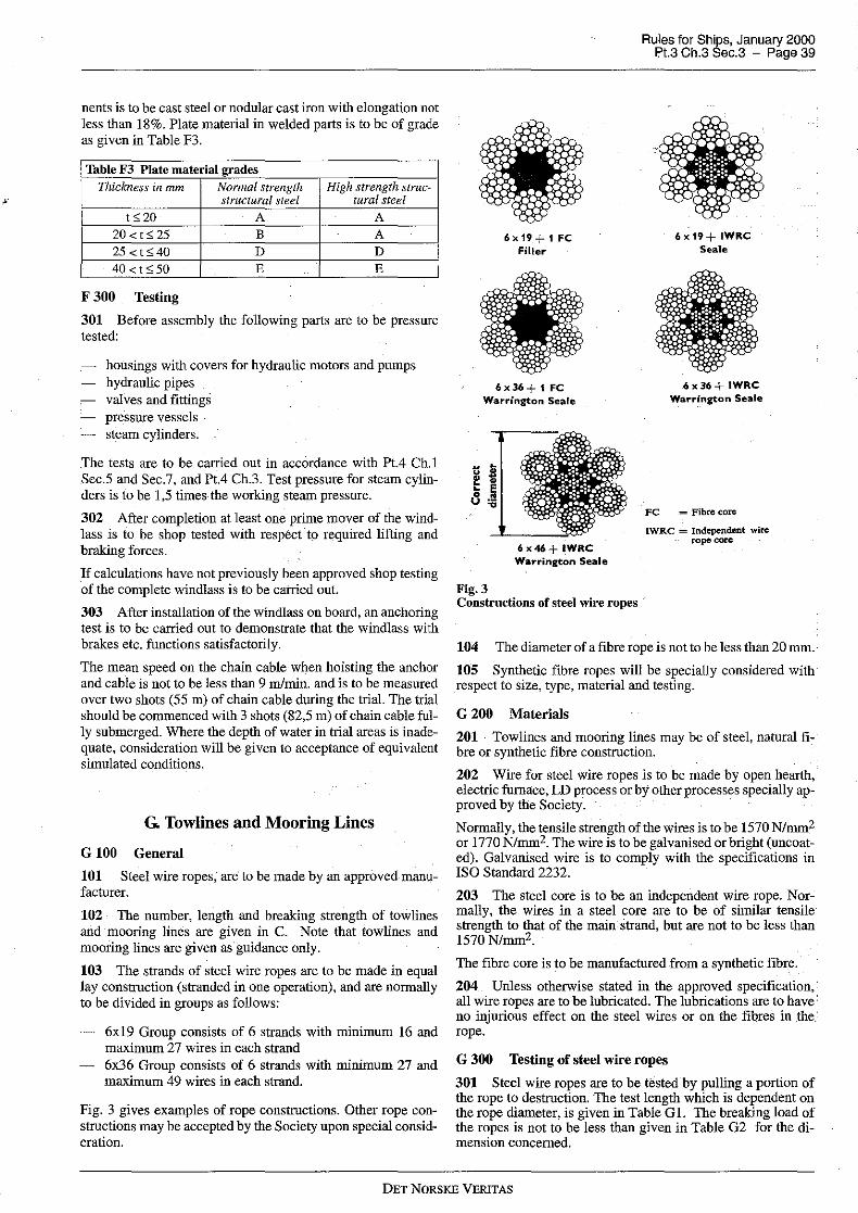
nents is to be cast steel or nodular cast iron with elongation not less than 18%. Plate material in welded parts is to be of grade as given in Table F3.
Table F3 Plate material grades Thickness in mm Nonna! strength High strength struc-
structural steel tural steel t,; 20 A A
20<t<25 B A 25 <t <40 D D
40<t:>50 E E
F 300 Testing
301 Before assembly the following parts are to be pressure tested:
housings with covers for hydraulic motors and pumps hydraulic pipes valves and fittings pressure vessels steam cylinders.
The tests are to be carried out in accordance with Pt.4 Ch.1 Sec.5 and Sec.7, and Pt.4 Ch.3. Test pressure for steam cylinders is to be 1,5 times- the working steam pressure.
302 After completion at least one prime mover of the windlass is to be shop tested with respect to required lifting and braking forces.
If calculations have not previously been approved shop testing of the complete windlass is to be carried out.
303 After installation of the windlass on board, an anchoring test is to be carried out to demonstrate that the windlass with brakes etc. functions satisfactorily.
The mean speed on the chain cable when hoisting the anchor and cable is not to be less than 9 m/min. and is to be measured over two shots (55 m) of chain cable during the trial. The trial should be commenced with 3 shots (82,5 m) of chain cable fully submerged. Where the depth of water in trial areas is inadequate, consideration will be given to acceptance of equivalent simulated conditions.
G. Towlines and Mooring Lines
G 100 General
101 Steel wire ropes, are to be made by an approved manufacturer.
102 The number, length and breaking strength of towlines and mooring lines are given in C. Note that towlines and mooring lines are given as· guidance only.
103 The strands of steel wire ropes are to be made in equal lay construction (stranded in one operation), and are normally to be divided in groups as follows:
6xl9 Group consists of 6 strands with minimum 16 and maximum 27 wires in each strand 6x36 Group consists of 6 strands with minimum 27 and maximum 49 wires in each strand.
Fig. 3 gives examples of rope constructions. Other rope constructions may be accepted by the Society upon special consideration.
6x19.+tFC Filler
6x36+1FC Warrington Seale
Fig.3
6x46+ IWRC Warrington Seale
Constructions of steel wire ropes
Rules for Ships, January 2000 Pt.3 Ch.3 Sec.3 - Page 39
6x19+ IWRC Seale
6x36+ IWRC Warrington Seale
FC = Fibre core
IWRC = Independent wire rope core
104 The diameter of a fibre rope is not to be less than 20 mm.
105 Synthetic fibre ropes will be specially considered with respect to size, type, material and testing.
G 200 Materials
201 Towlines and mooring lines may be of steel, natural fie bre or synthetic fibre construction.
202 Wire for steel wire ropes is to be made by open hearth, electric furnace; LD process or by other processes specially approved by the Society.
Normally, the tensile strength of the wires is to be 1570 N/mm2 or 1770 N/mm2. The wire is to be galvanised or bright (uncoated). Galvanised wire is to comply with the specifications in ISO Standard 2232.
203 The steel core is to be an independent wire rope. Normally, the wires in a steel core. are to be of similar tensile strength to that of the main strand, but are not to be less than 1570N/mm2.
The fibre core is to be manufactured from a synthetic fibre.
204 Unless otherwise stated in the approved specification, all wire ropes are to be lubricated. The lubrications are to have no injurious effect on the steel wires or on the fibres in the rope.
G 300 Testing of steel wire ropes
301 Steel wire ropes are to be rested by pulling a portion of the rope to destruction. The test length which is dependent on the rope diameter, is given in Table G 1. The breaking load of the ropes is not to be less than given in Table G2 for the dimension concerned.
DET NORSKE VERITAS

· Rules for Ships, January 2000 Pt.3 Ch.3 Sec.3 - Page 40
Table Gl Test lengths Rope diameter
in mm
d:;;6 6<d:;;20
d<20
Minimum test length in mm
300 600
30xd
Table G2 Test load and mass. Steel wire ropes Construction Norn. Minimum required breaking strength in kN Approximate mass
groups dia. 1570Nlmm2 mm
FC IWRC
6 x 19 group 14 J02 110 16 133 144 18 168 182 20 208 224 22 251 272 24 299 323 26 351 379 28 407 440 30 468 505
6 x 19 group 32 530 573 and 36 671 725
6 x 36 group 40 829 895 44 JOOO 1080 48 1190 1290 52 1400 1510 56 1620 1750 60 1860 2010 64 2290 68 2590
6x 36 group 72 2900 76 3230 80 3580 84 3950 88 4330 92 4730 96 5160 JOO 5590 104 6050 J08 6520 112 7020 116 7530 120 8060 124 8600 128 9170
C = fibre core
IWRC = independent wire rope core
302 If facilities are not available for pulling the complete cross section of the rope to destruction, the breaking load may be determined by testing separately 10% of all wires from each strand. The breaking strength of the rope is then considered to be:
f = average breaking strength of one wire in kN t = total number of wires k = lay factor as given in Table G3.
Table G3 Lay factor k Rope construction RopewithFC Rope with IWRD
group
6x 19 0,86 0,80 6x36 0,84 0,78
1770N!mm2 kg!JOOm
FC IWRC FC IWRC
115 124 72,7 82,0 150 162 94,9 107 190 205 120 135 234 253 148 167 283 306 179 202 337 364 214 241 396 428 251 283 459 496 291 328 527 569 334 376 598 646 380 428 757 817 480 542 934 JOJO 593 669 1130 1220 718 8JO 1350 1450 854 964 1580 17JO JOOO 1130 1830 1980 1160 13JO 2JOO 2270 1330 15JO
2580 17JO . 2920 1930
3270 2170 3640 2420 4040 2680 4450 2950 4880 3240 5340 3540 58JO 3850 63JO 4180 6820 4520 7360 4880 7910 5250 8490 5630 9080 6020 9700 6430 J0330 6850
303 The following individual wire tests are to be performed:
torsion test - reverse bend test - weight and uniformity of zink coating.
These tests are to be made in accordance with and are to comply with ISO Standard 2232.
G 400 Testing of natural fibre ropes
401 Natural fibre ropes are, if possible, to be tested by pulling a piece of the rope to destruction. For qualities 1 and 2, the breaking load is not to be less than given in Table G4.
DEf NORSKE VERITAS

Rules for Ships, January 2000 Pt.3 Ch.3 Sec.3 - Page 41
Table G4 Breaking loads. - natural fibre ropes 402 If facilities are not available for making the above test, the Society may accept testing of a specified number of the yarns from the rope. The breaking strength of the rope will then be deduced from these tests.
Ci re um-ference
mm
64 70 76 83 89 95 102 108 114 121 127 140 152 165 178 203 229 254 279 305
Breaking load (approximately) in kN
Three-stranded (hawser-laid)
Quality I Quality 2 31,6 28,2 37,6 33,4 44,8 39,8 52,0 46,3 59,5 53,1 68,0 60,5 76,4 68,0 85,2 75,7 95,4 84,7 105,l 93,4 116,1 103,l 139,0 123,5 163,9 145,5 190,8 169,4 219,7 195,3 282,5 251,l 353,3 313,9 433,0 384,7 520,2 462,1 617,0 548,2
Four-stranded (hawser-laid)
Quality I Quality 2 28,2 24,9 33,4 29,6 39,8 35,3
46,0 41,1 52,8 47,1 60,2 53,6
67,0 60,2 75,4 67,0 84,7 75,2
93,2 82,7 103,1 91,6 123,5 109,6
144,5 128,5 169,4 150,5 195,3 173,3
250,2 222,2 318,9 279,0 383,7 340,7
461,5 410,2 547,2 486,4
G 500 Mooring Winches
501
Guidance note: Each winch should be fitted with drum brakes the strength of which is sufficient to prevent unreeling of the mooring line when the rope tension is equal to 80 per cent of the breaking strength of the rope as fitted on the first layer.
Where this is achieved by the winch being fitted with a pawl and ratchet or other positive locking device, then the braking mechanism shall be such that the winch drum can be released in controlled manner while the mooring line is under tension.
For powered winches the maximum hauling tension which can be applied to the mooring line (the reeled first layer) should not be less than 1/4,5 times the rope's breaking strength and not more than 1/3 times the rope's breaking strength. For automatic winches these figures shall apply when the winch is set on the maximum power with automatic control.
The rendering tension which the winch can exert on the mooring line (reeled 1st layer) should not exceed 1,5 times, nor be less than 1,05 times the hauling tension for that particular power setting of the winch on automatic control. The winch is to be marked with the range of rope strength for which it is designed.
---e-n-d---of---G-u-i-d-a-n-c-e---n-o-t-e---
DET NORSKE VERITAS

·Rules for Ships, January 2000 Pt.3 Ch.3 Sec.4 - Page 42
SECTION 4 MASTS AND RIGGING
A. General
A 100 Introdnction
101 In this section the requirements to strength and support of masts, derrick posts and standing rigging are given.
102 The derricks and the cargo handling gear, are not subject to approval.
A 200 Assumptions
201 The cargo handling systems are assumed only to be operated in harbours or in sheltered waters.
202 The formulae for determining the scantlings of stayed masts, post and standing rigging are based on a symmetrical arrangement of stays and shrouds related to a vertical longitudinal plane through the mast or post.
Steel wire ropes. for shrouds are assumed with a modulus of elasticity equal to 7 ,5 x 106 N/mm2.
A 300 Definitions
301 Symbols:
p = Id =
I, = Im =
H =
a =
c
e =
L
load int which may be lifted by the derrick length of derrick in m. Where the working position of the derrick is such that the angle between the centre line of the derrick and the horizontal always exceeds 15°, Id is taken as the greatest horizontal projection of the derrick length of shrouds in m length of mast in m from deck or top of mast house to hounds height of derrick heel above deck or top of mast house inm athwartship distance in m from the mast to the deck at-tachment of shroud in question, see Fig. l longitudinal distance in m from the mast to the deck at-tachment of shroud in question, see Fig.l
With reference to a transverse plane through the mast, c is to be taken negative (-) for shrouds fitted on the same side as the derricks in question and positive ( +) for those fitted on the opposite side horizontal distance in m from the mast to the deck at-tachment of shroud in question, see Fig. 1.
aa. co and e0 refer to the shrouds nearest the transverse plane through the mast. c0 is not to be taken greater thanB/4. summation of:
a) Load functions for derricks simultaneously serving one hatch.
b) Support functions for effective shrouds when loads are as indicated in a), i.e. all shrouds forward or aft of the mast whichever is opposite to the hatch in question.
c) Load functions for derricks simultaneously working outboard.
d) Support functions for effective shrouds when loads are as indicated inc), i.e. all shrouds on one side of the ship, however the attachment to the deck is not to exceed 0,3 B forward or aft of the mast.
Co Co
Fig.1 Arrangement of shrouds.
A 400 Documentation
401 The following plans and information are to be submitted:
Arrangement plan showing location of mast or derrick post, standing rigging and cargo handling gear. Information about the operation of the derrick booms, if provided, i.e. how the derricks are intended to be worked, for instance, if more than one derrick is intended to simultaneously serve one hatch. Safe working load and working position for each provided derrick. Plan showing proposed scantlings of mast, derrick post and standing rigging. Plan showing supporting structures aud strengthening of hull in way of mast, post and standing rigging fastenings. Specification of the steel wire ropes intended to be used for standing rigging, indicating rope construction, scantlings and minimum breaking strength.
B. Materials and Welding
B 100 Materials
101 Selection of material grades for plates and sections is to be based on material thickness. NV-steel grades as given in Table B 1 will normally be accepted.
Table Bl Plate material grades Thickness Nonnal strength High strength
in mm structural steel structural steel
t520 A A
20<t525 B A 25 <t,; 40 D D 40 <t,; 50 E E
102 The tensile strength of wire ropes intended for shrouds and stays is normally to be minimum 1570 or 1770 N/mm2 (see Table G2 of Sec.3) and should not exceoed 2200 N/mm2.
103 Material certificates for standing rigging are to be issued by the manufacturer, confirming that the delivered products are manufactured and tested according to the Rules (see Sec.3 G) or another approved specification.
DET NORSKE VERITAS

B 200 Welding
201 Welding of important connections is to be carried out by welders approved by the Society.
202 Filler metals (electrodes) for welding are to be approved by the Society.
203 Important welds are to be inspected by radiography as required by the surveyor. Ultrasonic testing and magnetic-particle testing may also be required.
Radiographs are generally to meet the requirements to mark 4 (blue) according to «IIW Collection of Reference Radiographs of Welds». However, scattered porosity according to mark 3 (green) may be accepted.
C. Arrangement and Support
C 100 Masts and posts
101 Masts and posts are to be efficiently supported and connected to at least two decks or to one deck and a mast house top above. If the latter arrangement is adopted, the mast house top is to be of sufficient size and adequately stiffened. A winch house of usual size and scantlings is not considered to meet the requirements.
C 200 Standing rigging
201 The mast or post is to have at least two shrouds on each side of the centre line of the ship. The attachment of shrouds to mast is to be carefully made so as to reduce torsional strains as far as possible.
202 At fastenings for standing rigging and for guys and topping lifts, the deck is to be securely stiffened and reinforced for the additional loading.
D. Design and Scantlings
D 100 General
101 The requirements to diameter do and plate thickness to for masts and posts given in the following are to be maintained for a distance not less than I m above the derrick heel fitting. Above this level, the diameter and the plate thickness may be gradually reduced to 0,75 d0 and 0,75 to at the hounds. Minimum thickness is 7 ,5 mm.
102 Where masthead span blocks are attached to outriggers, the section modulus of the mast at the level of the outrigger is not to be less than:
Z= 120rQ (cm3)
r =: horizontal distance in m from mast to masthead span blocks on outrigger
LP
n
total load in t which may be lifted by the derricks on one side of the centre line of the ship 1, 2, 3 etc. for single, double and triple blocks etc., respectively.
Rules for Ships, January 2000 Pt.3 Ch.3 Sec.4 - Page 43
Minimum thickness of plating t = 7 ,5 mm.
Masts with outriggers on unusual spread will be specially considered.
D 300 Stayed masts or posts with derricks with a lifting capacity not exceeding 10 t
301 The outer diameter of masts or posts is not to be less than:
1
d0 = 140L/Pld)3
(mm)
302 The plate thickness of masts or posts is not to be less than:
t0 = 0,014 d0 mm, minimum 7,5 mm
303 The moment of inertia of masts or posts is not to be less than:
a
f
l 2 f 2 I = 240-m-~ (Pld)-1500/m3~ _.£._a (cm
4)
l -H..::., ..::., l 3 m s
0,5 for derricks with a lifting capacity of 5 tor less = 1,0 for derricks with a lifting capacity of 10 t. Between
5 and 10 t, a is determined by linear interpolation.
v 2 lOOq (cm )
V = breaking strength of shrouds in N q = tensile strength of shrouds in N/mm2.
D 400 Stayed masts of posts with derricks with a lifting capacity of 10 t or more, but not exceeding 40 t
401 The required outer diameter do in mm of masts or posts, measured at deck or top of mast house, is detennined from the expression:
d t 2
1~i 2' 1, 5'L,P + 10/m F
to = plate thickness of mast in mm at diameter d0 F = the greater of:
~ fc and !~f(l, 7a+ c) ..::., l 3 2..::- l 3
s s
402 The plate thickness of masts or posts is in no place to be less than 7 ,5 mm.
403 The moment of inertia of masts or posts is not to be less than:
103 Masts and posts are to be increased in tltickness or rein- G forced with doubling at the heel, deck and hounds.
the smaller of
D 200 Unstayed masts and posts with derricks
201 The section modulus and moment of inertia of masts and posts with derricks are not, at decks, to be less than:
DET NORSKE VERITAS
2
L,~ l 3 s
2 and !~f(l, 7a+c)
4.<:,, l 3 s
· Rules tor Ships, January 2000 Pt.3 Ch.3 Sec.4 - Page 44
404 Section modulus of masts is in general not to be less than:
G = as defined in 403.
3 (cm )
405 Where derricks are fitted both forward and aft of the mast, the section modulus is further not to be less than:
K
3 (cm )
L P1 l di and L P2 l dZ refer to derricks on either side ofa transverse plane through the mast.
L P 1 l di is to be the smaller of these products.
D 500 Stayed masts without derricks 501 The diameter of stayed masts without derricks is not to be less than:
100/ml do= -3- (mm)
d1 = 0,75 do (mm)
do and d1 are the diameter at deck and hounds respectively.
l ml = length of mast in m measured from deck to hounds.
502 The plate thickness is not to be less than:
t = 2,5 + 0,35 l ml (mm)
D 600 Shrouds 601 Shrouds for masts or posts with derricks are t<> have breaking strength not less than:
V= 10, SgolmL Pld
((kN)
(Im-Hi(!+ ~)Le Permanent centre line stays may be included in L e when relevant. 602 Shrouds for masts without derricks are to have circumference of steel wire rope not less than 63 mm.
DET NORSKE VERITAS

Rules for Ships, January 2000 Pt3 Ch.3 Sec.5 - Page 45
SECTIONS SEATS FOR ADDITIONAL LIFTING, TOWING OR MOORING EQUIPMENT
A. Crane Pedestals and Miscellaneous Lifting Posts
A 100 Introdnction
101 In this subsection the requirements for strength and support of crane pedestals, support of davits, A-frames and other lifting posts are given. The requirements are enforced for safe working load (SWL) > 30 kN or resulting bending moment on seat > 100 kNm.
102 The crane including pedestal flange and bolts or the lifting gear itself is not subject to approval, unless class notation CRANE, DSV or Crane Vessel is requested.
Guidance note: If n..o certification of lifting appliances is requested and DNV is to issue the certificate, approval of documentation will be required. See Rules for Certification of Lifting Appliances.
---e-n-d---of---G-u-i-d-a-n-c-e---n-o-t-e---
A 200 Documentation
201 The following plans and information are to be submitted:
Plans:
arrangement - pedestal/post with scantlings and grades of material - hull reinforcements.
For cranes on rails, also:
support of rails end buffers parking position with locking arrangement and hull reinforcements.
Information:
SWL - weight and weight moment of installation, in various lift-
ing positions.
For crane to be used offshore, also:
- dynaruic coefficient on working load - intended sea state for operation.
A 300 Materials and welding
301 For pedestal/posts to be used in harbour only, selection of material grade for plates and sections is to be based on Table Bl ofSec.4.
302 When intended for offshore use, the selection of materials is to be based on the Rules for Certification of Lifting Appliances.
The design temperature T 0 , for determination of the impact test temperature, is to be taken not less than -20°C, if not otherwise specified.
303 When a pedestal subjected to bending is not slotted through a deck plating with t > 10 mm, the following applies:
either Z-quality material (Pt.2 Ch.2 Sec.1 E400) is to be used in the deck plating or an ultrasonic laruination test after the welding has been completed, is to be carried out in tension exposed areas.
A 400 Arrangement
401 For large loads see Fig.1 and Fig.2.
-- - ---Fig.1 Not recommended support.
Fig.2 Recommended support.
A 500 Design loads
I I
----
501 For operation of crane or lifting gear in harbour SWL to be multiplied by a dynaruic coefficient 1,3, if not otherwise specified.
502 For cranes and lifting gears for offshore use, the following is to be taken into account:
The dynaruic coefficient on SWL, specified by designer and checked against the minimum values of the Rules for Certification of Lifting Appliances. Vertical and horizontal accelerations for the specified sea state. a,,, "t and a1 to be taken as a safe fraction of the extreme values given in Ch. l Sec.4 B. Accelerations to be combined as indicated for deck equipment in Ch. l Sec.4 C500.
Guidance note: When the significant wave height Hs is known,
DET NORSKE VERITAS

· Rules for Ships, January 2000 Pt.3 Ch.3 Sec.5 - Page 46
may be inserted in the formulae of Ch.1 Sec.4 B.
Wind forces for the specified wind velocity, according to the Rules for Certification of Lifting Appliances.
---e-n-d---of---G-u-i-d-a-n-c-e---n-o-t-e---
503 When the transit condition is considered critical, the design loads are to be taken as given for idle deck equipment in Ch. I Sec.4 C500.
For non-compact units wind and icing are to be taken into account as appropriate.
Standard ice load for North Sea winter conditions may be taken as 5 cm ice deposit on wind and weather exposed surfaces.
504 For survival craft davits, the dynamic coefficient is to be taken as 2.2.
505 · For man-overboard boats, davits to withstand a horizontal towing force.
A 600 Allowable stresses
601 Allowable stresses in structural steel elements will in principle be:
( •. Yciccel"'d"o"'r--'b=uccckli=·n"g"-=linu=·t") (any hull stresses) O'a or 'ta = -
I, 5k I, 5
when elastic analysis is applied. Yield limit for high strength steel is to be taken as 235 fl> unless a fatigue control is carried out. For definition off1 see Ch.I Sec.2.
k 1,0 for davit supports made of high tensile steel = 0,85 for davit supports made of mild steel.
In cases of combined stresses, the equivalent stress ( von Mises) is to be applied for the yield control.
Guidance note: For lifting operation in harbour supported by a single girder in lifting direction the following simplified calculation procedure may be applied (see Fig. 3):
Total load: P = 1,3 SWL + crane weight Crane moment:M ':= i,3 MsWL + Mweight
Shear force diagrams as induced by P and M are given in Fig. 3.
Total shear forces given by:
Left side of crane: Ql M bP
= -+-l l
M aP Right side of crane: Q, = l + l
Maximum bending moments:
Leftside: M1 = Qz(a-~)
Right side: M, = Q,( b - ~)
Q1 orQ, Required shear area: A = --"---'
~.
M 1orM, Required section modulus: Z =
O'a
---e-n-d---of---G-u-i-d-a-n-c-e---n-o-t-e---
An appropriate moment of inertia is left to designers discretion. ·
Guidance note: Buckling strength requirements for circular columns will usually be satisfied when thickness~ 0,01 x diameter.
---e-n-d---of---G-u-i-d-a-n-c-e---n-o-t-e---
SWL
_M_ l
Fig. 3 Crane support girder.
a
l
- e-P
(j\ ,_M
I : I
I I L
b
M d
,,
_M_ l
B. Seatings for Winches, Windlasses and other Pulling Accessories
B 100 Introduction. 101 In this subsection requirements for seatings for pulling, towing and mooring equipment in general are given. This equipment is usually not subject to classification, unless in connection with an additional class notation (i.e. towing equipment for tugs).
102 Seatings for bow anchor equipment has been dealt with in Sec.3 B.
B 200 Documentation 201 When breaking load of wire or chain is > 150 kN, the following plans and information are to be submitted:
DET NORSKE VERITAS

Plans:
arrangement, indicating
location of brake, motor and any wire pin or chain stopper top or bottom entrance of wire to drum
seating, with quality of materials hull reinforcements.
Information:
- design loads.
B 300 Design loads
301 Design loads were dealt with for
- bow anchor windlasses and chain stoppers in Sec.3 F - mooring winches in Sec.3 G.
302 In general the following may have to be considered:
With motor in action:
rated motor moment SWL x dynamic coefficient (for lifting devices) or maximum pulling force.
With brake in action:
Rules for Ships, January 2000 Pt.3 Ch.3 Sec.5 - Page 47
1,5 x brake moment/ 1,5 x brake holding force on first layer, based on standard friction coefficient 0,3 80 % of breaking load for a mooring, or towing wire/chain when no pin/stopper . · 45 % when a wire pin or chain stopper is fitted.
With pin or stopper in action:
- 80 % of breaking load of wire/chain.
B 400 Calculation of stresses
401 Guidance note: A wire force will oscillate between drum bearings, whereas the moment will be held at the motor or brake end, whichever is in action, and carried to their respective seatings.
---e-n-d---of---G-u-i-d-a-n-c-e---n-o-t-e---
B 500 Allowable stresses. Materials 501 Allowable stresses in structural steel will be as for lifting equipment, A600. Grades of material will be considered.
502 Materials of elements to be welded to the deck are preferably to be of ship quality steel of the same strength group as the deck itself. Deck doublers to be avoided if tension perpendicular to deck occurs. When deck plating is subjected to tension in the thickness direction, either z-quality material (Pt.2 Ch.2 Sec. I E400) or a lamination test after finished welding may be required. Full penetration welds may be considered.
DET NORSKE VERITAS

Rules for Ships, January 2000 Pt.3 Ch.3 App.A - Page 48
APPENDIX A ADDITIONAL REQUIREMENTS FOR NON - DUPLICATED RUDDER
ACTUATORS
A. Introdnction
A 100 Scope
101 The requirements given in this Appendix are in compliance with IMO «Guidelines» for the acceptance of non-duplicated rudder actuators for oil carriers, chemical carriers and liquefied gas carriers of 10 000 tons gross and upwards but of less than 100 000 tonnes deadweight.
B. Materials
B 100 Special Requirements
101 Parts subject to internal hydraulic pressure or transmitting mechanical forces to the rudder-stock are to be made of duly tested ductile materials complying with recognised standards. Materials for pressure retaining components are to be in accordance with recognised pressure vessel standards. These materials are not to have an elongation less than 12% nor a tensile strength in excess of 650 N/mm2.
C. Design
C 100 Design pressure
101 The design pressurt: should be assu1ned to be at least equal to the greater of the following:
1,25 times the maximum working pressure to be expected under the operating conditions required in Sec.2 Jl02.b) the relief valve(s) setting.
C 200 Analysis
201 In order to analyse the design the following are required:
The manufacturers of rudder actuators should submit detailed calculations showing the suitability of the design for the intended service. A detailed stress analysis of the pressure retaining parts of the actuator should be carried out to determine the stresses at the design pressure. Where considered necessary because of the design complexity or manufacturing procedures, a fatigue analysis and fracture mechanics analysis may be required. In connection with these analyses, all foreseen dynamic loads should be taken into account. Experimental stress analysis may be required in addition to, or in lieu of, theoretical calculations depending upon the complexity of the design.
C 300 Dynamic loads for fatigue and fracture mechanics analysis
301 The assumptions for dynamic loading for fatigue and fracture mechanics analyses where required in 200 and in Sec.2 J205, JI 102 are to be submitted for appraisal. Both the case of high cycle and cumulative fatigue are to be considered.
C 400 Allowable stresses
401 For the purpose of determining the general scantlings of parts of rudder actuators subject to internal hydraulic pressure the allowable stresses are not to exceed:
O'm $f
cr1Sl,5f
\Vhere
O'b $ 1,5 f
O'J + O'b $ 1,5 f
O'm + O'b $ 1,5 f
O'm = equivalent primary general membrane stress cr1 equivalent primary local membrane stress crb = equivalent primary bending stress
f at at
the lesser of As or B
a ts specified minimum tensile strength of material at ambient temperature
O'f = specified minimum yield stress or 0,2 % proof stress of material at ambient temperature.
A and B are as follows:
Table Cl Permissible primary membrane stress Steel Cast steel Nodular cast iron
A 4 4,6 5,8 B 2 2,3 3,5
C 500 Burst test
501 Pressure retaining parts not requiring fatigue analysis and fracture mechanics analysis may be accepted on the basis of a certified burst test and the detailed stress analysis required by 200 need not be provided.
The minimum bursting pressure is to be calculated as follows:
where
Pa = PA c;ta c;ts
Pa = minimum bursting pressure P = design pressure as defined in 100 A = as from table in 400 c; ta = actual tensile strength c; ts = tensile strength as defined in 400.
D. Construction Details
D 100 General
101 The construction should be such as to minimise local concentrations of stress.
D200 Welds
201 The welding details and welding procedures should be approved. All welded joints within the pressure boundary of a rudder actuator or connection parts transmitting mechanical loads should be full penetration type or of equivalent strength.
D 300 Oil seals
301 Oil seals forming part of the external pressure boundary are to comply with Sec.2 J209 and J2!{).
D 400 Isolating valves
Isolating valves are to be fitted at the connection of pipes to the actuator, and should be directly mounted on the actuator.
DET NORSKE VERITAS

D 500 Relief valves
501 Relief valves for protecting the rudder actuator against overpressure as required in Sec.2 J305 are to comply with the following:
The setting pressure is not to be less than 1,25 times the maximum working pressure expected under operating conditions required by Sec.2 J102.b). The minimum discharge capacity of the relief valve(s) is to be not less than 110% of the total capacity of all pumps which provide power for the actuator. Under such conditions the rise in pressure should not exceed 10% of the setting pressure. In this regard due consideration should be given to extreme foreseen ambient conditions in respect of oil viscosity.
Rules for Ships, January 2000 Pt.3 Ch.3 App.A - Page 49
E. Testing.
E 100 Non-destructive testing
101 The rudder actuator should oe subjected to suitable and complete non-destructive testing to detect both surface flaws and volumetric flaws. The procedure and acceptance criteria for non-destructive testing should be in accordance with requirements of recognised standards. If found necessary, fracture mechanics analysis may be used for determining maximum allowable flaw size.
E 200 Other testing
201 Tests, including hydrostatic tests, of all pressure parts at 1,5 times the design pressure should be carried out.
202 When installed on board the ship, the rudder actuator should be subjected to a hydrostatic test and a running test.
DET NORSKE VERITAS
