horizontal machining center hs series -...
TRANSCRIPT
Horizontal Machining Center
HS Series

Peripheral Device
Easy to Operate
● ATC & Magazine● Machining● Peripheral Equipment
● HW-PGi F● HW-TIDM● HW-TM
Basic Structure● Bed● Slide Way● Spindle
Horizontal Machining Center

Revolution of Productivity, Next Generation,High Performance, High Efficiency Horizontal Machining Center
HS Series
HYUNDAI WIA MACHINE TOOL 2 3
•Adopt Roller Guide for each axes
•Double Winding Powerful Spindle Motor
•The heaviest maximum load in its class
•Big plus Spindle (BT Tool Common)
•2 steps gear driven type for the heavy duty cutting (HS6300/8000)
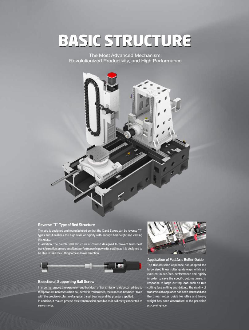
BASIC STRUCTUREThe Most Advanced Mechanism,
Revolutionized Productivity, and High Performance
In order to remove the expansion and backlash of transmission axis occurred due to temperature increases when ball screw is transmitted, the bisection has been fixed with the precise 4 column of angular thrust bearing and the pressure applied. In addition, it makes precise axis transmission possible as it is directly connected to servo motor.
The transmission appliance has adapted the large sized linear roller guide ways which are excellent in acc./dec. performance and rigidity in order to save the specific cutting times. In response to large cutting load such as mid cutting face milling and drilling, the rigidity of transmission appliance has been increased and the linear roller guide for ultra and heavy weight has been assembled in the precision processing face.
Bisectional Supporting Ball Screw
Application of Full Axis Roller Guide
The bed is designed and manufactured so that the X and Z axes can be reverse “T” types and it realizes the high level of rigidity with enough bed height and casting thickness. In addition, the double wall structure of column designed to prevent from heat transformation proves excellent performance in powerful cutting as it is designed to be able to take the cutting force in X axis direction.
Reverse “T” Type of Bed Structure

Spindle Power & Torque
[ ] : OptionSpecification of main spindle
The main spindle has improved the cutting capacity more and more with powerful tool-clamping forces as well as made assurance doubly sure for the factors which determine the rigidity for main spindle housing and used angular ball bearing. In addition, the AC spindle motor can perform a high speed processing in addition to mid cutting without any problem in 30 horse power and 8,000r/min, and the standard spindle to be cooled off by oil is designed in a structure to minimize the transformation by heat.
For the HS6300/8000 designed in a gear type, it is able to perform the transmission of main spindle.
It makes wide range of processing realized to ensure the powerful torque at lower speed while secure rotation at higher speed with the transmission for gear type of main spindle adapted.
Built in Spinlde The main spindle designed in built in motor structure restricts the vibration and heat in maximum which can occur at high speed of rotation and make the quick acc./dec. speed realized, and keeps the secure precision under the high speed of mid cutting operation. In particular, it has realized the high speed processing of 15,000r/min, max. of rotation number of main Spindle by supporting it with pressurized P4 grade of high precision bearing.
The main spindle of HS Series guarantees the secure processing as it is equipped with oil cooling system of main spindle in standard in order to minimize the heal displacement occurred when product processing.
Cooling System of Main Spindle
HYUNDAI WIA MACHINE TOOL 4 5
Spindle Taper
Gear Type Spindle
It is possible to cut at high speed as the clamping increases and the vibration decreases if the main spindle standard for 2 sides of restriction (BBT) which the main spindle and taper sections are simultaneously contacted is applied.
Before Clamping After Clamping
Clamping
Non Contact Contact
Axial Movement is Important for Face Contact
HS6300/8000
Spindle
• Rigidity improved due to increases of reference diam.• Improvement of ATC repeat precision• Prevention of Z axis displacement when rotating in high speed• Increased life cycle of tools
HS5000/50, HS6300/800012,000rpm Built-in
HS5000/50, HS6300/800012,000rpm Built-in
HS5000/50, HS6300/800012,000rpm Built-in
HS5000/50, HS6300/800012,000rpm Built-in
Application of 2 Faces Restriction Spindle
ITEMTaper
Spindle Speed
Power (Max./Cont.)
Torque (Max./Cont.)
Driving Method
Big Plus #40
150~12,000
25/22 (33.5/30)
167/95
Built-in
Big Plus #40
150~15,000
25/22 (33.5/30)
167/95
Built-in
Big Plus #50
120~12,000
30/25 (40/33.5)
420/238
Built-in
Big Plus #50
8,000 [8,000] [12,000]
22/18.5 [26/22] [30/25]
781/657 [922/781] [420/238]
Gear [Gear] [Built-in]
-
r/min
kW(HP)
N.m
-
HS4000i/5000i HS4000/5000 HS5000/50 HS6300/8000
[ ] : 선택사양【 주축사양 】

PERIPHERAL DEVICE
The magazine of HS Series has been designed to be able to store 40 ea as a standard and 120 ea tools as an option depending on the machine type. In addition, the servo motor guarantees the quick movement of tools and the fixed address method increasesthe convenience of operations.
Item HS4000i/4000 HS5000i/5000 HS5000(50) HS6300/8000
Attachment quantity of tools 40ea [60, 80, 120ea] 40ea [60, 80, 120ea] 40ea [60ea] 40ea [60, 90, 120ea]
Standard of tools BBT40 [HSK-A63] BBT40 [HSK-A63] BBT50 [HSK-A100] BBT50 [HSK-A100]
Max. diam. of tool/ ø75mm / ø140mm ø75mm / ø140mm ø125mm / ø250mm ø125mm / ø245mm
if the neighboring port is empty (2.9″/5.5″) (2.9″/5.5″) (4.9″/9.8″) (4.9″/9.8″)
Max. length of tools 300mm(11.8″) 400mm(15.7″) 450mm(17.7″) 500mm(19.6″)
Max. weight of tools 8kg 8kg 25kg 15kg [25kg]
Selection method of tools Fixed address Fixed address Fixed address Fixed address
1.2sec 1.5sec 2sec 3.5sec
3.6sec 4sec 6sec 7sec
Exchanging
time of tools
T - T
C - C
[ ] : OptionSpecification of ATC
The Twin Arm guarantees the tool exchanging in a high speed and dramatically decreases the specific cutting time.
Automatic Tool Change
Magazine
MachiningAPC
FACE MILL, S45C
Ø125 mm x 8F
650 r/min
1,038 mm/min
100 mm
6 mm
623 cc/min
U-DRILL, S45C
Ø50 mm
1,146 r/min
286 mm/min
50 mm
50 mm
561 cc/min
TAP, S45C
M52 x P5.0
42 r/min
210 mm/min
52 mm
60 mm
HS8000 (8,000r/min)
HS5000 (15,000r/min)
FACE MILL, S45C
Ø80 mm x 6F
1,137 r/min
1,000 mm/min
70 mm
5 mm
350 cc/min
DRILL, S45C
Ø43 mm
199 r/min
39 mm/min
43 mm
60 mm
57 cc/min
TAP, S45C
Diam. of tools
Rotation numbers of main Spindle
Transmission speed
Cutting width
Cutting depth
Chip emissions
Diam. of tools
Rotation numbers of main Spindle
Transmission speed
Cutting width
Cutting depth
Chip emissions
Diam. of tools
Rotation numbers of main Spindle
Transmission speed
Cutting width
Cutting depth
Diam. of tools
Rotation numbers of main Spindle
Transmission speed
Cutting width
Cutting depth
Chip emissions
Diam. of tools
Rotation numbers of main Spindle
Transmission speed
Cutting width
Cutting depth
Chip emissions
Diam. of tools
Rotation numbers of main Spindle
Transmission speed
Cutting width
Cutting depth
M33 x P3.5
70 r/min
280 mm/min
36 mm
54 mm
HYUNDAI WIA MACHINE TOOL 6 7
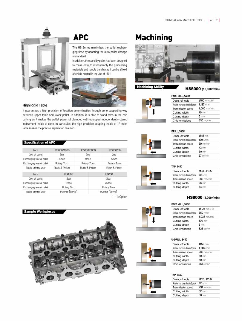
The HS Series minimizes the pallet exchan-ging time by adapting the auto pallet change in standard.In addition, the stand by pallet has been designed to make easy to disassembly the processing materials and handle the chip as it can be affixed after it is rotated in the unit of 180°.
It guarantees a high precision of location determination through cone supporting way between upper table and lower pallet. In addition, it is able to stand even in the mid cutting as it makes the pallet powerful clamped with equipped independently clamp instrument inside of cone. In particular, the high precision coupling inside of 1° index table makes the precise separation realized.
High Rigid Table
Machining Ability
Specification of APC
Sample Workpieces
Item HS4000/4000i HS5000/5000i HS5000/50
Qty. of pallet 2ea 2ea 2ea
Exchanging time of pallet 10sec 11sec 12sec
Exchanging way of pallet Rotary Turn Rotary Turn Rotary Turn
Table driving way Rack & Pinion Rack & Pinion Rack & Pinion
Item HS6300 HS8000
Qty. of pallet 2ea 2ea
Exchanging time of pallet 12sec 25sec
Exchanging way of pallet Rotary Turn Rotary Turn
Table driving way Invertor [Servo] Invertor [Servo]
[ ] : Option

Easy to Operate
Programming system for creating CNC programs easily.
HYUNDAI WIA's smart system is capable of more rapid program setting and readily maintaining, and is optimal to the productivity of machine.
M-Code List ⓄⓅ Calculator ⓄⓅ Product Guide ⓄⓅ

HYUNDAI WIA MACHINE TOOL 8 9HYUNDAI WIA MACHINE TOOL 8 9
Easy to Operate
Programming system for creating CNC programs easily.
HYUNDAI WIA's smart system is capable of more rapid program setting and readily maintaining, and is optimal to the productivity of machine.
HW-PGi FProgramming Guide i for Fanuc System
HW-TIDM : Tool ID Manager ⓄⓅ
HW-TM : Tool Monitoring System ⓄⓅ
HW-TM• Real-time cut monitoring• 2 Channel screen display • Self learning for machining amount • 3 stage of status monitoring (wear/break/no-load)
Realistic 3D solid animationPrograming is simulated
Example of easy programmingReadily programing with interactive type, without code
Engraving CycleIf characters are enteterd as C axis control, when the character is only entered without
separate program is programmed automatically.
• Customer oriented tool ID management system (ID MAP setting function)
•RS232C/PROFI DP protocol•Tool counter function•Tool management automation
Data Carriers
Tools
Read/Write Head
Processor
❖ If you order these options, Please contact sales person
Tool ID System Diagram
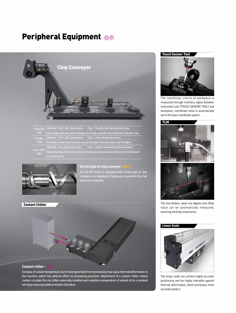
Peripheral Equipment ⓄⓅ
Coolant Chiller
Screw type of chip conveyor (Std.)As the HS Series is equipped with screw type of chip conveyor as a standard, it helps you to perform the chip treatment smoothly.
Increase of coolant temperature due to heat generated from processing may cause thermal deformation to the machine, which has adverse effect on processing precision. Attachment of a coolant chiller makes coolant circulate thru its chiller externally installed and maintains temperature of coolant oil to a constant set value ensuring stable precision of product.
Coolant chiller - ⓄⓅ
Touch Sensor Tool
The machining criteria of workpiece is measured through interface signal between instrument unit (TOUCH SENSOR TOOL) and workpiece, cooridinate value is automatically set in the basic coordinate system.
Linear Scale
The linear scale can achieve highly accurate positioning and be highly tolerable against thermal deformation, which processes more accurate product.
TLM
The tool broken, wear-out degree and offset value can be automatically measured, ensuring working convenience.
Chip Conveyor
Hinge Belt Type
Scraper Type
Drum Filter Type
Material SS41, 45C, Steel casting Chip Roughly cut chips Synthetic chips
Material SS41, 45C, Steel casting Chip Chips shortly cut and out
Material AL, casting, non-metal Chip Chips in low density and fine powder
Show highly efficiency when treating lots of chips synthetic chip treatment, collective chips
Facilitate to treat chip shortly cut and out, facilitate to forward chips with 90 degree
Have advantage in precision when processing aluminum because chips are not introduced
to coolant nozzle
HYUNDAI WIA MACHINE TOOL 10 11
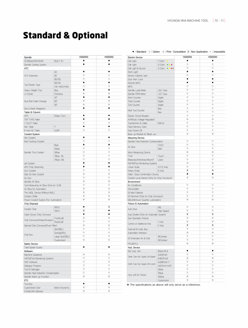
Standard & Optional
Call Light
Call Light
Call Light & Buzzer
Work Light
Electric Cabinet Light
Door Inter-Lock
Remote MPG
MPG
Spindle Load Meter
Spindle RPM Meter
Work Counter
Total Counter
Tool Counter
Multi Tool Counter
Electric Circuit Breaker
AVR(Auto Voltage Regulator)
Transformer & Cable
Flash Memory Card
Auto Power Off
Back up Module for Black out
Mesuring Device
Spindle Heat Distortion Compensation
Air Zero
Work Measuring Device
"TLM
(Marposs/Renishaw/Bloom)"
HWTM(Tool Monitoring System)
Linear Scale
Rotary Scale
Pallet Close Confirmation Device
Coolant Level Sensor (Only for Chip Conveyor)
Enviornment
Air Conditioner
Dehumidifier
Oil Mist Collector
Oil Skimmer (Only for Chip Conveyor)
MQL(Minimum Quantity Lubrication)
Fixture & Automation
Auto Door
Auto Shutter (Only for Automatic System)
Sub Operation Pannel
Control of Additional Axis
External M code 4ea
Automation Interface
I/O Extension (In & Out)
PPL(6PPL)
Hyd. Device
Std. Hyd. Unit
Center Type Hyd. Supply Unit (Upper)
Center Type Hyd. Supply Unit (Lower)
Hyd. Unit for Fixture
❖ The specifications as above will only serve as a reference.
HS4000i HS5000i
● ●
○ ○
○ ○
● ●
○ ○
● ●
● ●
○ ○
○ ○
○ ○
○ ○
○ ○
○ ○
○ ○
○ ○
○ ○
☆ ☆
○ ○
○ ○
○ ○
☆ ☆
○ ○
○ ○
○ ○
☆ ☆
○ ○
○ ○
☆ ☆
○ ○
X X
● ●
☆ ☆
○ ○
○ ○
○ ○
○ ○
☆ ☆
○ ○
○ ○
X X
☆ ☆
☆ ☆
X X
○ ○
☆ ☆
○ ○
○ ○
☆ ☆
● ●
○ ○
☆ ☆
○ ○
○ ○
○ ○
○ ○
☆ ☆
☆ ☆
Electric Device
12,000rpm(25/22kW)
Spindle Cooling System
ATC
ATC Extension
Tool Shank Type
Heavy Weight Tool
U-Center
Stud Bolt Collet Change
Servo Motor Magazine
Table & Column
APC
TAP TYPE Pallet
T-SLOT Pallet
Std. Table
B Axis NC Table
Coolant System
Std. Coolant
Bed Flushing Coolant
Spindle Thru Coolant
Jet Coolant
APC Chip Cleanning
Gun Coolant
Side Oil Hole Coolant
Air Gun
Spindle Air Blow
Tool Measuring Air Blow (Only for TLM)
Air Blow for Automation
Thru MQL Device (Without MQL)
Coolant Chiller
Power Coolant System (For Automation)
Chip Disposal
Coolant Tank
Cabin Screw Chip Conveyor
Chip Conveyor(Hinge/Scraper)
Special Chip Conveyor(Drum Filter)
Chip Box
Safety Device
Total Splash Guard
Software
Machine Guidance
HWTM(Tool Monitoring System)
DNC Software
Dialogue Program
Tool ID Manager
Spindle Heat Distortion Compensation
Spindle Warm up Function
ETC
Tool Box
Customized Color
CAD&CAM Software
BUILT-IN
40
60
80/120
BBT40
HSK-A63/CAT#40
8kg
D'andrea
45°
60°
90°
Rotary Turn
1°
0.001°
6bar
20bar
30bar
70bar, 15L
70bar, 30L
600ℓ
700ℓ
Front(Left)
Rear(Left)
Std.(180L)
Swing(200L)
Large Size(330L)
Customized
Need for Munsel No.
1 Color : ■
3 Color : ■■■
3 Color : ■■■B
LED Type
LED Type
Digital
Digital
Digital
6ea
9ea
50kVA
TACO
SMC
Touch
Laser
X/Y/Z Axis
B Axis
Std.
High Speed
1 Axis
2 Axis
16Contact
32Contact
65bar/45ℓ
2x2(4Port)
2x6(12Port)
2x3(6Port)-1°
2x6(12Port)-0.001°
45bar
70bar
100bar
Customized
HS4000i HS5000i
● ●
● ●
● ●
○ ○
○ ○
● ●
○ ○
● ●
☆ ☆
● ●
☆ ☆
☆ ☆
● ●
● ●
● ●
○ ○
● ●
○ ○
● ●
- -
● ●
○ ○
○ ○
○ ○
○ ○
● ●
● ●
○ ○
☆ ☆
○ ○
☆ ☆
○ ○
☆ ☆
☆ ☆
☆ ☆
☆ ☆
● X
X ●
● ●
☆ ☆
○ ○
☆ ☆
○ ○
○ ○
○ ○
☆ ☆
● ●
☆ ☆
○ ○
○ ○
○ ○
○ ○
○ ○
☆ ☆
● ●
☆ ☆
☆ ☆
Spindle
● : Standard ○ : Option ☆ : Prior Consultation X : Non Application - : Impossible
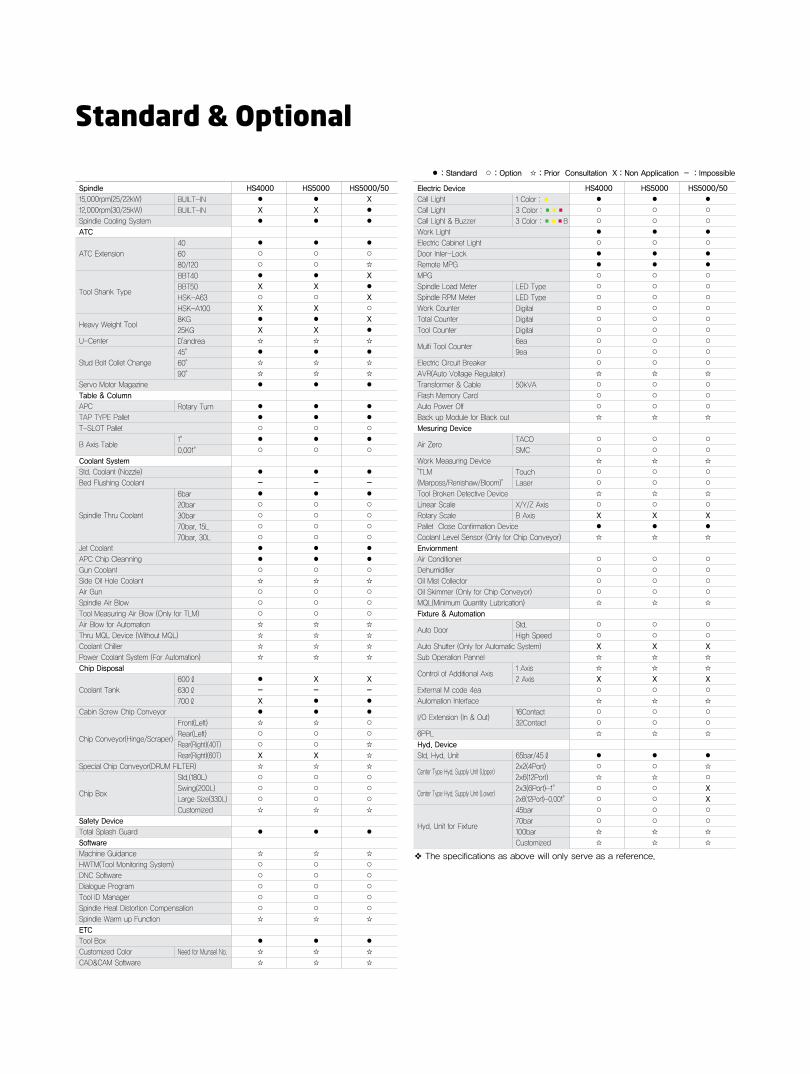
Standard & Optional
Call Light
Call Light
Call Light & Buzzer
Work Light
Electric Cabinet Light
Door Inter-Lock
Remote MPG
MPG
Spindle Load Meter
Spindle RPM Meter
Work Counter
Total Counter
Tool Counter
Multi Tool Counter
Electric Circuit Breaker
AVR(Auto Voltage Regulator)
Transformer & Cable
Flash Memory Card
Auto Power Off
Back up Module for Black out
Mesuring Device
Air Zero
Work Measuring Device
"TLM
(Marposs/Renishaw/Bloom)"
Tool Broken Detective Device
Linear Scale
Rotary Scale
Pallet Close Confirmation Device
Coolant Level Sensor (Only for Chip Conveyor)
Enviornment
Air Conditioner
Dehumidifier
Oil Mist Collector
Oil Skimmer (Only for Chip Conveyor)
MQL(Minimum Quantity Lubrication)
Fixture & Automation
Auto Door
Auto Shutter (Only for Automatic System)
Sub Operation Pannel
Control of Additional Axis
External M code 4ea
Automation Interface
I/O Extension (In & Out)
6PPL
Hyd. Device
Std. Hyd. Unit
Center Type Hyd. Supply Unit (Upper)
Center Type Hyd. Supply Unit (Lower)
Hyd. Unit for Fixture
❖ The specifications as above will only serve as a reference.
HS4000 HS5000 HS5000/50
● ● ●
○ ○ ○
○ ○ ○
● ● ●
○ ○ ○
● ● ●
● ● ●
○ ○ ○
○ ○ ○
○ ○ ○
○ ○ ○
○ ○ ○
○ ○ ○
○ ○ ○
○ ○ ○
○ ○ ○
☆ ☆ ☆
○ ○ ○
○ ○ ○
○ ○ ○
☆ ☆ ☆
○ ○ ○
○ ○ ○
☆ ☆ ☆
○ ○ ○
○ ○ ○
☆ ☆ ☆
○ ○ ○
X X X
● ● ●
☆ ☆ ☆
○ ○ ○
○ ○ ○
○ ○ ○
○ ○ ○
☆ ☆ ☆
○ ○ ○
○ ○ ○
X X X
☆ ☆ ☆
☆ ☆ ☆
X X X
○ ○ ○
☆ ☆ ☆
○ ○ ○
○ ○ ○
☆ ☆ ☆
● ● ●
○ ○ ☆
☆ ☆ ○
○ ○ X
○ ○ X
○ ○ ○
○ ○ ○
☆ ☆ ☆
☆ ☆ ☆
Electric Device
15,000rpm(25/22kW)
12,000rpm(30/25kW)
Spindle Cooling System
ATC
ATC Extension
Tool Shank Type
Heavy Weight Tool
U-Center
Stud Bolt Collet Change
Servo Motor Magazine
Table & Column
APC
TAP TYPE Pallet
T-SLOT Pallet
B Axis Table
Coolant System
Std. Coolant (Nozzle)
Bed Flushing Coolant
Spindle Thru Coolant
Jet Coolant
APC Chip Cleanning
Gun Coolant
Side Oil Hole Coolant
Air Gun
Spindle Air Blow
Tool Measuring Air Blow (Only for TLM)
Air Blow for Automation
Thru MQL Device (Without MQL)
Coolant Chiller
Power Coolant System (For Automation)
Chip Disposal
Coolant Tank
Cabin Screw Chip Conveyor
Chip Conveyor(Hinge/Scraper)
Special Chip Conveyor(DRUM FILTER)
Chip Box
Safety Device
Total Splash Guard
Software
Machine Guidance
HWTM(Tool Monitoring System)
DNC Software
Dialogue Program
Tool ID Manager
Spindle Heat Distortion Compensation
Spindle Warm up Function
ETC
Tool Box
Customized Color
CAD&CAM Software
BUILT-IN
BUILT-IN
40
60
80/120
BBT40
BBT50
HSK-A63
HSK-A100
8KG
25KG
D'andrea
45°
60°
90°
Rotary Turn
1°
0.001°
6bar
20bar
30bar
70bar, 15L
70bar, 30L
600ℓ
630ℓ
700ℓ
Front(Left)
Rear(Left)
Rear(Right)(40T)
Rear(Right)(60T)
Std.(180L)
Swing(200L)
Large Size(330L)
Customized
Need for Munsel No.
1 Color : ■
3 Color : ■■■
3 Color : ■■■B
LED Type
LED Type
Digital
Digital
Digital
6ea
9ea
50kVA
TACO
SMC
Touch
Laser
X/Y/Z Axis
B Axis
Std.
High Speed
1 Axis
2 Axis
16Contact
32Contact
65bar/45ℓ
2x2(4Port)
2x6(12Port)
2x3(6Port)-1°
2x6(12Port)-0.001°
45bar
70bar
100bar
Customized
HS4000 HS5000 HS5000/50
● ● X
X X ●
● ● ●
● ● ●
○ ○ ○
○ ○ ☆
● ● X
X X ●
○ ○ X
X X ○
● ● X
X X ●
☆ ☆ ☆
● ● ●
☆ ☆ ☆
☆ ☆ ☆
● ● ●
● ● ●
● ● ●
○ ○ ○
● ● ●
○ ○ ○
● ● ●
- - -
● ● ●
○ ○ ○
○ ○ ○
○ ○ ○
○ ○ ○
● ● ●
● ● ●
○ ○ ○
☆ ☆ ☆
○ ○ ○
○ ○ ○
○ ○ ○
☆ ☆ ☆
☆ ☆ ☆
☆ ☆ ☆
☆ ☆ ☆
● X X
- - -
X ● ●
● ● ●
☆ ☆ ○
○ ○ ○
○ ○ ☆
X X ☆
☆ ☆ ☆
○ ○ ○
○ ○ ○
○ ○ ○
☆ ☆ ☆
● ● ●
☆ ☆ ☆
○ ○ ○
○ ○ ○
○ ○ ○
○ ○ ○
○ ○ ○
☆ ☆ ☆
● ● ●
☆ ☆ ☆
☆ ☆ ☆
Spindle
● : Standard ○ : Option ☆ : Prior Consultation X : Non Application - : Impossible

Call Light
Call Light
Call Light & Buzzer
Work Light
Electric Cabinet Light
Door Inter-Lock
Remote MPG
MPG
Spindle Load Meter
Spindle RPM Meter
Work Counter
Total Counter
Tool Counter
Multi Tool Counter
Electric Circuit Breaker
AVR(Auto Voltage Regulator)
Transformer & Cable
Flash Memory Card
Auto Power Off
Back up Module for Black out
Mesuring Device
Air Zero
Work Measuring Device
"TLM
(Marposs/Renishaw/Bloom)"
Tool Broken Detective Device
Linear Scale
Rotary Scale
Pallet Close Confirmation Device
Coolant Level Sensor (Only for Chip Conveyor)
Enviornment
Air Conditioner
Dehumidifier
Oil Mist Collector
Oil Skimmer (Only for Chip Conveyor)
MQL(Minimum Quantity Lubrication)
Fixture & Automation
Auto Door
Auto Shutter (Only for Automatic System)
Sub Operation Pannel
Control of Additional Axis
External M code 4ea
Automation Interface
I/O Extension (In & Out)
PPL(6PPL)
Hyd. Device
Std. Hyd. Unit
Center Type Hyd. Supply Unit (Upper)
Center Type Hyd. Supply Unit (Lower)
Hyd. Unit for Fixture
❖ The specifications as above will only serve as a reference.
HS6300 HS8000
● ●
○ ○
○ ○
● ●
○ ○
● ●
● ●
○ ○
○ ○
○ ○
○ ○
○ ○
○ ○
○ ○
○ ○
○ ○
☆ ☆
○ ○
○ ○
○ ○
☆ ☆
○ ○
○ ○
○ ○
○ ○
○ ○
☆ ☆
○ ○
○ ○
● ●
☆ ☆
○ ○
○ ○
○ ○
○ ○
☆ ☆
○ ○
☆ ☆
X X
☆ ☆
☆ ☆
X X
○ ○
☆ ☆
○ ○
○ ○
☆ ☆
● ●
☆ ☆
☆ ☆
○ ○
○ ○
X X
○ ○
○ ○
○ ○
☆ ☆
Electric Device
8,000rpm(22/18.5kW)
8,000rpm(26/22kW)
12,000rpm(30/26kW)
Spindle Cooling System
ATC
ATC Extension
Tool Shank Type
Heavy Weight Tool
U-Center
Stud Bolt Collet Change
Servo Motor Magazine
Table & Column
APC
TAP TYPE Pallet
T-SLOT Pallet
B Axis Table
Coolant System
Std. Coolant (Nozzle)
Bed Flushing Coolant
Spindle Thru Coolant
Jet Coolant
Gun Coolant
Side Oil Hole Coolant
Air Gun
Spindle Air Blow
Tool Measuring Air Blow (Only for TLM)
Air Blow for Automation
Thru MQL Device (Without MQL)
Coolant Chiller
Power Coolant System (For Automation)
Chip Disposal
Coolant Tank
Cabin Screw Chip Conveyor
Chip Conveyor(Hinge/Scraper)
Special Chip Conveyor(Drum Filter)
Chip Box
Safety Device
Total Splash Guard
Software
Machine Guidance
HWTM(Tool Monitoring System)
DNC Software
Dialogue Program
Tool ID Manager
Spindle Heat Distortion Compensation
Spindle Warm up Function
ETC
Tool Box
Customized Color
CAD&CAM Software
GEAR(2STEP)
GEAR(2STEP)
BUILT-IN
40
60
90
120
BBT50
25kg
D'andrea
45°
60°
90°
Rotary Turn
1°
0.001°
20bar
30bar
70bar, 15L
70bar, 30L
800ℓ
Front(Left)
Left(Rear)
Std.(180L)
Swing(200L)
Large Size(330L)
Customized
Need for Munsel NO.
1 Color : ■
3 Color : ■■■
3 Color : ■■■B
LED Type
LED Type
Digital
Digital
Digital
6ea
9ea
50kVA
TACO
SMC
Touch
Laser
X/Y/Z Axis
B Axis
Std.
High Speed
1 Axis
2 Axis
16Contact
32Contact
50bar/60ℓ
2x2(4Port)
2x4(8Port)
2x6(12Port)
2x3(6Port)
2x6(12Port)
45bar
70bar
100bar
Customized
HS6300 HS8000
● ●
○ ○
○ ○
● ●
● ●
○ ○
○ ○
○ ○
● ●
○ ○
☆ ☆
○ ○
○ ○
● ●
○ ○
● ●
● ●
○ ○
● ●
○ ○
● ●
○ ○
☆ ☆
○ ○
○ ○
○ ○
○ ○
○ ○
☆ ☆
○ ○
○ ○
○ ○
☆ ☆
☆ ☆
☆ ☆
☆ ☆
● ●
● ●
○ ○
☆ ☆
☆ ☆
○ ○
○ ○
○ ○
☆ ☆
● ●
☆ ☆
○ ○
○ ○
○ ○
○ ○
○ ○
☆ ☆
● ●
☆ ☆
☆ ☆
Spindle
HYUNDAI WIA MACHINE TOOL 12 13
● : Standard ○ : Option ☆ : Prior Consultation X : Non Application - : Impossible

APC SWING Max.=�1520(59.8″)
REAR CHIP CONVEYOR
WORK AREA Max.=�660(25.9″)
2350(92.5″) (STD.40T,OPT.60T)580(22.8″)
2930(115.3″) (OPT.80T,120T)
737(29.0″)
APC TOP COVER
ATC MAG.
ATC ARM MOTOR
21
60
(85
.0″)
25
30
(99
.6″)
26
24
(10
3.3
″)
ATC ARM MOTOR
899(35.4″)4610(181.5″)3122(122.9″)
3249(127.9″)
11
77
(46
.3″)
21
60
(85
.0″)
(S
TD
.40
T,
OP
T.8
0T
)
29
85
(11
7.5
″) (
OP
T.6
0T,1
20
T)
ATC MAG.
95
0(3
7.4
″)
97
0(3
8.2
″)9
70
(38
.2″)
19
40
(76
.4″)
23
03
(90
.6″)
57
5
(22
.6″)
2225(87.6″) 2225(87.6″)
4480(176.4″) 763(30″)
98
6(3
8.8
″)
33
36
(13
1.3
″)
APC SWING Max.=�1760(69.3″)
WORK AREA Max=�760(29.9″)
FRONT
CHIP CONVEYOR
REAR
CHIP CONVEYOR
2770(109″) (STD.40T,OPT.60T)580(22.8″)
3330(131.1″) (OPT.80T,120T)
ATC ARM MOTORATC ARM MOTOR
1050(4
1.3
″)
2720(1
07″)
4860(191.3″)
2300(9
0.5
″) (
ST
D.4
0T,O
PT.8
0T
)
2986(1
17.5
″) (
OP
T.6
0T,1
20T
)
2300(9
0.5
″)
2767(1
08.9
″)
1480(58.3″)3848(151.2″)
4250(167.3″)
2470(97.2″) 2265(89.2″)
602
(23.7″)
1080(4
2.5
″)1080(4
2.5
″)
2380(9
3.7
″)
2770(1
09″)
1488(5
8.5
″)
R579(22.8
″)
560
(22″)
4132(1
62.6
″)1362(5
3.6
″)
1100(4
3.3
″)
4735(172.2″)
APC TOP COVER
ATC MAG.ATC MAG.
R534(21″)
FRONT
CHIP CONVEYOR
848(33.3″) 3000(118″) 675(26.5″) 1052(41.4″)
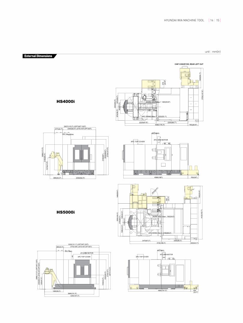
unit : mm(in)
Specifications
External Dimensions
HS4000
HS5000
APC SWING Max.=�1520(55.1″)
CHIP CONVEYOR, REAR LEFT OUT
WORK AREA Max.=�660(59.8″)
APC TOP COVER
ATC MagazineATC MAG.
ATC ARM MOTOR
763(30″)4580(180″)
21
60
(85
″)
25
30
(99
.6″)
27
34
(10
7.6
″)
899(35.3″) 2350(92.5″)
12
15
(47
.8″)2
16
0(8
5.0
″)
29
85
(11
7.5
″)
2350(92.5″) (STD.40T,OPT.60T)577(22.7″)
2927(115.2″) (OPT.80T,120T)
95
3(3
7.5
″)
97
0(3
8.2
″)9
70
(38
.2″)
23
03
(90
.6″)
57
5
(22
.6″) 14
00
(55
.1″)
37
50
(14
7.6
″)
2225(87.6″) 2255(88.7″)
4480(176.3″) 763(28.9″)
APC SWING Max.=�1760(69.2″)
WORK AREA Max=�760(29.9″)
1100
(43.
3″)
2300
(90.
5″)
2720
(107
″)28
77(1
13.3
″)
2770(109″) (STD.40T,OPT.60T)560(22.0″)3330(131.1″) (OPT.80T,120T)
1480(58.2″)3848(151.5″)
4250(167.3″)
1200
(47.
2″)
2300
(90.
5″) (
STD
.40T
,OPT
.80T
)29
86(1
17.5
″) (O
PT.6
0T,1
20T)
APC TOP COVER
ATC MAG.
ATC ARM MOTOR
4860(191.3″) 604(23.7″)
1105
(43.
5″)
1080
(42.
5″)
1080
(42.
5″)
2160
(85.
0″)
2550
(100
.4″)
1488
(58.
6″)
R579(2
2.8″)
560
(22.
0″)
2265(89.2″)2470(97.2″)4735(186.4″) 602(23.7″)
1362
(53.
6″)
4132
(162
.7″)
APC TOP COVER
ATC ARM MOTORATC MAG.
unit : mm(in)
External Dimensions
HS4000i
HS5000i
HYUNDAI WIA MACHINE TOOL 14 15

unit : mm(in)
Specifications
External Dimensions
2800
(110
.2″)
3220
(126
.7″)
3525
(138
.7″)
4063(160″)
4336(170.7″)595(23.4″)
2800
(110
.2″)
Y-AXIS MOTOR
CHIP CONVEYORFRONT, LEFT OUT
5081(200.0″) (STD.40T)5471(215.4″)(OPT.60T)
6495(255.7″)(OPT.90T)
7519(296.0″)(OPT.120T)
970(
38.1
″) 1400
(55.
1″)
1400
(55.
1″)
2800
(110
.2″)
3575
(140
.7″)
3230(127.2″)2550(100.5″)
5780(227.5″)
APC SWING Max. �2340(92.1″)
Max. WORK AREA �1000(39.3″)
775(
30.5
″)
761(
29.9
″)
1358
(53.
4″)
CH
IP C
ON
VEYO
R
MES
H C
HIP
CO
NVE
YOR
R789(3.1″)
R298(11.7″)
R650(25.5″)
1538(60.5″)
2800(110.2″)775(30.5″)
APC TOP COVER
Y-AXIS MOTOR
1200
(47.
2″)
28
00
(11
0.2
″)
32
00
(12
5.9
″)
35
25
(13
8.7
″)
1458(57.4″)
4063(159.9″)
4418(173.9″)595(23.4″)
72
5(2
8.5
″)
13
58
(53
.4″)
5216(205.3″) (STD.40T)
5606(220.7″)
(OPT.60T)
6630(261.0″)
(OPT.90T)
7654(301.3″)
(OPT.120T)
97
0(3
8.1
″)
14
80
(58
.2″)
14
80
(58
.2″)
29
60
(11
6.5
″)
36
55
(14
3.8
″)
CH
IP C
ON
VE
YO
R
ME
SH
CH
IP C
ON
VE
YO
R
3280(129.1″)2635(103.7″)
5915(232.8″)
2960(116.5″)695(27.3″)
APC SWING Max.=�2550(143.9″)
Max. WORK AREA=�1200(47.2″)
Y-AXIS MOTORY-AXIS MOTOR
APC TOP COVER
CHIP CONVEYORFRONT LEFT OUT
ATC MAG.
R789(31.0″)
R298(11.7″)
R650(25.5″)
HS6300
HS8000

unit : mm(in)
Table Dimensions
HYUNDAI WIA MACHINE TOOL 16 17
400 (15.7) 500 (19.7)
500
(19.
7)
560
(22)
200
(7.9
)20
0 (7
.9)
100(3.9)
100(3.9)
150 (5.9) 150 (5.9)
100(3.9)
100(3.9)
400
(15.
7)
460
(18.
1)
25 (1
)
25 (1)210 (8.3) 250 (9.8)
75(3)
75(3)
55(2.2)
55(2.2)
12 (0.5
)
12 (0
.5)
36 (1.4
)
160
(6.3
)16
0 (6
.3)
80(3.1)
80(3.1)
80(3.1)
80(3.1)
120(4.7)
120(4.7)
18 (0.7)
25 (1
)
18 (0.7)
18 (0
.7)
18 (0
.7)
Ø18 (Ø0.7) Ø18 (Ø0.7)
2-Ø18 (Ø0.7)
18 (0.7) 18 (0.7)30 (1.2) 30 (1.2)
30 (1.2
)
2-Ø18 (Ø0.7)
T-SlotTAP
HS4000i/4000
HS6300 (HS8000)
HS5000i/5000
T-Slot TypeTap Type

unit : mm
Tool Shank
HS5000(50)/6300/8000
HS4000i/4000 HS5000i/5000
BBT #40 (Standard)
HSK-A63 (Option)
BBT40, BIG PLUS CAT40, PULL STUD BOLTBBT40, BIG PLUS CAT40, PULL STUD BOLT
Tool Shank BT50 Tool
[MAS 403 BT50]
Pull Stud Bolt
[BT50-90°]
Spindle Thru Coolant
CAT40
Specifications

HYUNDAI WIA MACHINE TOOL 18 19
HS4000i HS5000i HS4000 HS5000 HS5000/50
400×400 500×500 400×400 500×500
(15.8″×15.8″) (19.7″×19.7″) (15.8″×15.8″) (19.7″×19.7″)
2 - 500 (1,102) 2 - 800 (1,764)
Ø660×H650 Ø760×H850 Ø660×H650 Ø760×H850 Ø800×H980
(Ø26″×H25.6″) (Ø29.9″×H33.5″) (Ø26″×H25.6″) (Ø29.9″×H33.5″) (Ø31.5″×H38.6″)
1° [0.001°]
BIG PLUS #40 BIG PLUS #50
150 ~ 12,000 150 ~ 15,000 150 ~ 12,000
25/22 (33.5/30) 30/25 (40.2/33.5)
167 / 95 420 / 238
BUILT IN
620/560/650 850/700/750 620/560/650 850/700/750
(24.4″/22″/25.6″) (33.5″/27.6″/29.5″) (24.4″/22″/25.6″) (33.5″/27.6″/29.5″)
50 ~ 610 (2″ ~ 24″) 50~750 (2″ ~ 29.5″) 50 ~ 610 (2″ ~ 24″) 50~750 (2″ ~ 29.5″) 75~775 (3″ ~ 30.5″)
150 ~ 800 150 ~ 900 150 ~ 800 150 ~ 900
(5.9″ ~ 31.5″) (5.9″ ~ 35.4″) (5.9″ ~ 31.5″) (5.9″ ~ 35.4″)
50/50/50 (1,969/1,969/1,969)
50 (1,969) 40 (1,575)
ROLLER GUIDE
40 [60, 80, 120]
BBT40 [HSK-A63] BBT50 [HSK-A100]
Ø75/Ø140 Ø125/Ø250
(Ø3″/Ø5.5″) (Ø4.9″/Ø9.8″)
300 (11.8″) 400 (15.7″) 300 (11.8″) 400 (15.7″) 450 (17.7″)
8 (17.6) 25 (54.7)
FIxED ADRESS
1.2 1.5 1.2 1.5 2.0
3.6 4 3.6 4 6
2
ROTARY TURN
10 11 10 11 11
600 (158.5) 630 (166.4) 600 (158.5) 630 (166.4)
3 (0.8)
45 (11.9)
500 (132.1)
60
Over 35 Over 50
220 / 60 (200 / 50)
2,350×4,580 2,770×4,860 2,350×4,580 2,770×4,860 3,225×4,990
(92.5″×180.3″) (109.1″×191.3″) (92.5″×180.3″) (109.1″×191.3″) (127″×196.4″)
2,664 (104.9″) 2,804(110.4″) 2,985 (117.5″) 2,767(108.9″) 3,067 (120.7″)
10,000 (22,046) 15,000 (33,069) 10,000 (22,046) 15,000 (33,069) 17,000 (37,478)
FANUC 32i-A
TABlE
Table Size
Maximum Load Capacity
Maximum Working Size
Min. Indexing Angle
Spindle Taper
Spindle RPM
Spindle Motor Output (Max./Cont.)
Spindle Torque (Max./Cont.)
Spindle Driving Method
Travel (x/Y/Z axis)
Distance from Column to SP. center
Distance from Table Surface to Sp
Rapid Feed Rate (x/Y/Z)
Cutting Feed Rate (x/Y/Z)
Slide Type
Number of Tools
Tool Shank
Max. Tool Dia. (W.T/W.O)
Max. Tool Length
Max. Tool Weight
Tool Selection Method
Tool Change Time T-T
C-C
No. of Pallet
APC Type
APC Change Time
Coolant Tank
Lubricating Tank
Spindle Cooling Unit
Air Consumption (0.5MPa)
Electric Power Supply
Thickness of Power Cable
Voltage
Floor Space (L×W)
Height
Weight
Controller
FEED
TANkCAPACITy
SPINDlE
ATC
APC
MACHINE
NC
POwERSuPPly
❖ Specifications are subject to change for improvement without notice.
mm(in)
kgf(lbf)
mm(in)
deg
-
r/min
kW(HP)
N·m
-
mm(in)
mm(in)
mm(in)
m/min(ipm)
m/min(ipm)
EA
-
mm(in)
mm(in)
kg(lb)
-
sec
sec
EA
-
sec
ℓ(gel)
ℓ(gel)
ℓ(gel)
ℓ/min
KVA
Sq
V/Hz
mm(in)
mm(in)
kg(lb)
-
ITEM
Specifications
[ ] : Option
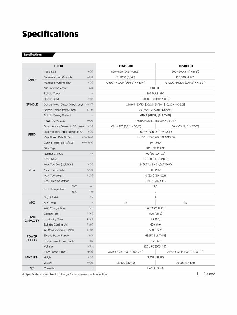
Specifications
HS6300 HS8000
630×630 (24.8″×24.8″) 800×800(31.5″×31.5″)
2-1,200 (2,646) 2-1,600 (3,527)
Ø930×H1,000 (Ø36.6″×H39.4″) Ø1,200×H1,100 (Ø47.2″×H43.3″)
1° [0.001°]
BIG PLUS #50
8,000 [8,000] [12,000]
22/18.5 (30/25) [26/22 (35/30)] [30/25 (40/33.5)]
781/657 [922/781] [420/238]
GEAR [GEAR] [BUILT-IN]
1,050/875/875 (41.3″/34.4″/34.4″)
100 ~ 975 (3.9″ ~ 38.4″) 80~955 (3.1″ ~ 37.6″)
150 ~ 1,025 (5.9″ ~ 40.4″)
50 / 50 / 50 (1,969/1,969/1,969)
50 (1,969)
ROLLER GUIDE
40 [60, 90, 120]
BBT50 [HSK-A100]
Ø125/Ø245 (Ø4.9″/Ø9.6″)
500 (19.7)
15 (33.1) [25 (55.1)]
FIxEDD ADRESS
3.5
7
2
12 25
ROTARY TURN
800 (211.3)
2.7 (0.7)
60 (15.9)
500 (132.1)
53 [50:BUILT-IN]
Over 50
220 / 60 (200 / 50)
3,575×5,780 (140.6″×227.6″) 3,655 x 5,915 (143.9″×232.9″)
3,525 (138.8″)
25,000 (55,116) 26,000 (57,320)
FANUC 31i-A
TABlE
Table Size
Maximum Load Capacity
Maximum Working Size
Min. Indexing Angle
Spindle Taper
Spindle RPM
Spindle Motor Output (Max./Cont.)
Spindle Torque (Max./Cont.)
Spindle Driving Method
Travel (x/Y/Z axis)
Distance from Column to SP. center
Distance from Table Surface to Sp
Rapid Feed Rate (x/Y/Z)
Cutting Feed Rate (x/Y/Z)
Slide Type
Number of Tools
Tool Shank
Max. Tool Dia. (W.T/W.O)
Max. Tool Length
Max. Tool Weight
Tool Selection Method
Tool Change Time T-T
C-C
No. of Pallet
APC Type
APC Change Time
Coolant Tank
Lubricating Tank
Spindle Cooling Unit
Air Consumption (0.5MPa)
Electric Power Supply
Thickness of Power Cable
Voltage
Floor Space (L×W)
Height
Weight
Controller
FEED
TANkCAPACITy
SPINDlE
ATC
APC
MACHINE
NC
POwERSuPPly
❖ Specifications are subject to change for improvement without notice.
mm(in)
kgf(lbf)
mm(in)
deg
-
r/min
kW(HP)
N·m
-
mm(in)
mm(in)
mm(in)
m/min(ipm)
m/min(ipm)
EA
-
mm(in)
mm(in)
kg(lb)
-
sec
sec
EA
-
sec
ℓ(gel)
ℓ(gel)
ℓ(gel)
ℓ/min
KVA
Sq
V/Hz
mm(in)
mm(in)
kg(lb)
-
ITEM
Specifications
[ ] : Option

Controller
HYUNDAI WIA MACHINE TOOL 20 21
FANUC 32i-A
4 (X, Y, Z, B) axes
3 axes (G00 & G01 : 3 axes,
G02 & G03 : 2 axes)
0.001 mm (0.0001″)/1 deg
0.001 mm (0.0001″)/1 deg
G20 / G21
Each axis / All axes
All axes
Over-travel
+/- 0~9999 pulse
(rapid traverse & cutting feed)
10.4″ color LCD
Sequence, program
Rapid, jog, handle
x1, x10 , x100
F code feedrate direct command
0~200% (10% unit)
0~5,000 mm/min (197 ipm)
F0, F25%, F50%, F100%
Positioning/Linear/Circular
(G00/G01/G02/G03)
G61 / G09
G04, 0~9999.9999sec
Controlled axes
Simultaneous
controllable axes
Least input increment
Least command increment
Inch / metric conversion
Interlock
Machine lock
Emergency stop
Stored stroke check 1
Mirror image
Follow-up
Servo off
Backlash compensation
Position switch
Stored pitch error
compensation
LCD/MDI
Automatic operation (memory)
MDI operation
Search function
Program restart
Dry run
Single block
Buffer register
Manual jog feed
Manual handle feed rate
Feed command
Feedrate override
Jog feed
Rapid traverse override
Override cancel
Rapid traverse bell-shaped
acceleration/deceleration
Label skip
Control in/out
Interpolation functions
Exact stop mode / Exact stop
Dwell
Helical interpolation
Axis control / Display unit
Feed functions
Program input & Interpolation functions
Operation
•Figures in inch are converted from metric values. •Design and specifications subject to change without notice.
10 Mbps
320 m (128Kbyte)
125 ea
Copy, move, change of NC program
Alarm & operator message
Screen saver
#500 to #999
G60
G30P3, G30P4
100 Mbps
9 ea (Application can be limited)
3 unit
640 m (256 Kbyte) / 1280 m (512 Kbyte)
KDNC (S/W)
Memory card input/output
Embedded ethernet
Part program storage length
Registered programs
Memory lock
Back ground editing
Extended part program editing
External message
Self-diagnosis function
History display
Help function
Run hour / Parts count display
Actual cutting feedrate display
Graphic display
Spindle / Servo setting screen
Multi-language display
Erase CRT screen display
Additional 1 axis
Addition to custom macro
common variables
Polar coordinate
command / interpolation
Cylindrical interpolation
Single direction positioning
Tool length measurement
3rd and 4th Reference
point return
External data input
Remote buffer
Ethernet
Data server
Ai contour control (AICC)
Ai nano contour control
(AI nano CC)
Manual Guide i
Optional block skip add
Handle interrupt
Manual handle feed
Part program storage
Dynamic graphic display
DNC operation
Data input/output & Editing functions
Setting, display, diagnosis
Option
G28
G27
G30
M00, M01 / M02, M30
EIA RS-244 / ISO 840
(Automatic recognition)
1 ea
+/- 9999.9999″ (+/- 8 digits)
O4 digit
G90 / G91
G17, G18, G19
G52~G59
48 pairs
“ON” fixed
G10
4 levels of nesting
#100 to #199
G73, G74, G76, G80 ~ G89
G31
M2 digits
S5 digits, binary output
50% ~ 120% (10% unit)
Max. T8 digits
G40~G42
G43, G44, G49
+/- 6 digits
99 pairs
RS232C
Threading/synchronous feed
Manual reference point return
1st Reference point return
Reference point return check
2nd Reference point return
Program stop/end
Tape code
Optional block skip
Maximum programmable
dimensions
Program number
Absolute and incremental command
Decimal point input
Plane selection
Work coordinate system setting
Additional work coordinate system
Manual absolute
Programmable data input
Sub program call
Custom macro B
Circular interpolation by radius R
Canned cycle
Optional chamfering/corner R
Skip function
Automatic coordinate
system setting
Coordinate system rotation
Programmable mirror image
Miscellaneous function
Miscellaneous function lock
Spindle speed command
Spindle speed override
Spindle orientation
Rigid tapping
Tool function
Cutter compensation C
Tool length compensation
Tool offset amount
Tool offset pairs
Tool life management
Reader/Puncher interface
Program input & Interpolation functions
Auxiliary / Spindle functions
Tool functions / Tool compensation
Data input/output & Editing functions
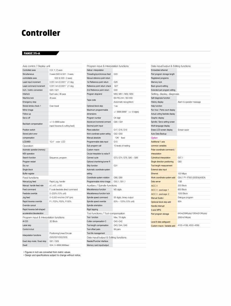
Controller
FANUC 31i-A
Controlled axes
Simultaneous
controllable axes
Least input increment
Least command increment
Inch / metric conversion
Interlock
Machine lock
Emergency stop
Stored stroke check 1
Mirror image
Follow-up
Servo off
Backlash compensation
Position switch
Stored pitch error
compensation
LCD/MDI
Automatic operation (memory)
MDI operation
Search function
Program restart
Dry run
Single block
Buffer register
Manual jog feed
Manual handle feed rate
Feed command
Feedrate override
Jog feed
Rapid traverse override
Override cancel
Rapid traverse bell-shaped
acceleration/deceleration
AI CCI
Label skip
Control in/out
Interpolation functions
Exact stop mode / Exact stop
Dwell
3 (X, Y, Z) axes
3 axes (G00 & G01 : 3 axes,
G02 & G03 : 2 axes)
0.001 mm (0.0001″)/1 deg
0.001 mm (0.0001″)/1 deg
G20 / G21
Each axis / All axes
All axes
Over-travel
+/- 0~9999 pulse
(rapid traverse & cutting feed)
10.4″ color LCD
Sequence, program
Rapid, jog, handle
x1, x10 , x100
F code feedrate direct command
0~200% (10% unit)
0~5,000 mm/min (197 ipm)
F1, F25%, F50%, F100%
3D Block
Positioning/Linear/Circular
(G00/G01/G02/G03)
G61 / G09
G04, 0~9999.9999sec
Program input & Interpolation functions
•Figures in inch are converted from metric values. •Design and specifications subject to change without notice.
Alarm & operator message
Screen saver
G07.1
G60
100 Mbps
G54.1 P1~P300 (300EA)/(40EA)
1GB
200 Block
600 Block
1000 Block
Dialogue program
9EA
640m(256Kbyte)/1280m(512Kbyte)/
2560m(1Mbyte)
#100~#199, #500~#599
G33
G28
G27
G30
M00, M01 / M02, M30
EIA RS-244 / ISO 840
(Automatic recognition)
1 ea
+/- 9999.9999″ (+/- 8 digits)
O4 digit
G90 / G91
G17, G18, G19
G52~G59
“ON” fixed
G10
10 levels of nesting
G73, G74, G76, G80 ~ G89
G31
G68, G69
G50.1, G51.1
M3 digits
S5 digits, binary output
50% ~ 120% (10% unit)
Max. T8 digits
G40~G42
G43, G44, G49
99 pairs
Helical interpolation
Threading/synchronous feed
Manual reference point return
1st Reference point return
Reference point return check
2nd Reference point return
Program stop/end
Tape code
Optional block skip
Maximum programmable
dimensions
Program number
Absolute and incremental command
Decimal point input
Plane selection
Work coordinate system setting
Manual absolute
Programmable data input
Sub program call
Custom macro
Circular interpolation by radius R
Canned cycle
Optional chamfering/corner R
Skip function
Automatic coordinate system
setting
Coordinate system rotation
Programmable mirror image
Miscellaneous function
Miscellaneous function lock
Spindle speed command
Spindle speed override
Spindle orientation
Rigid tapping
Tool function
Cutter compensation C
Tool length compensation
Tool offset pairs
Tool life management
Reader/Puncher interface
Memory card input/output
Embedded ethernet
Part program storage length
Registered programs
Memory lock
Back ground editing
Extended part program editing
Self-diagnosis function
History display
Help function
Run hour / Parts count display
Actual cutting feedrate display
Graphic display
Spindle / Servo setting screen
Multi-language display
Erase LCD screen display
Auto Data Backup
Additional 1 axis
common variables
Polar coordinate command /
interpolation
Cylindrical interpolation
Single direction positioning
Tool length measurement
External data input
Ethernet
Work coordinate system add
Data server
AICC II
AICC II package 1
AICC II package 2
Manual Guide i
Optional block skip add
Handle interrupt
3-axis MPG
Part program storage
Leval 8 data safeguard
Custom macro Variable add
Axis control / Display unit
Operation
Feed functions
Program input & Interpolation functions
Tool functions / Tool compensation
Data input/output & Editing functions
Auxiliary / Spindle functions
Data input/output & Editing functions
Setting, display, diagnosis
Option
HYUNDAI WIA MACHINE TOOL 22 23
ENERGY SAVING & ECO FRIENDLY
All machine tools of HYUNDAI WIA are
designed to consider environmental safety and energy saving
Minimum practice enabling coexistence of humankind and machines...
HYUNDAI WIA will lead for this
MQL : Minimal Quantity Lubrication Energy Saving
Economy Lubrication SystemOil Skimmer
Mist Collector
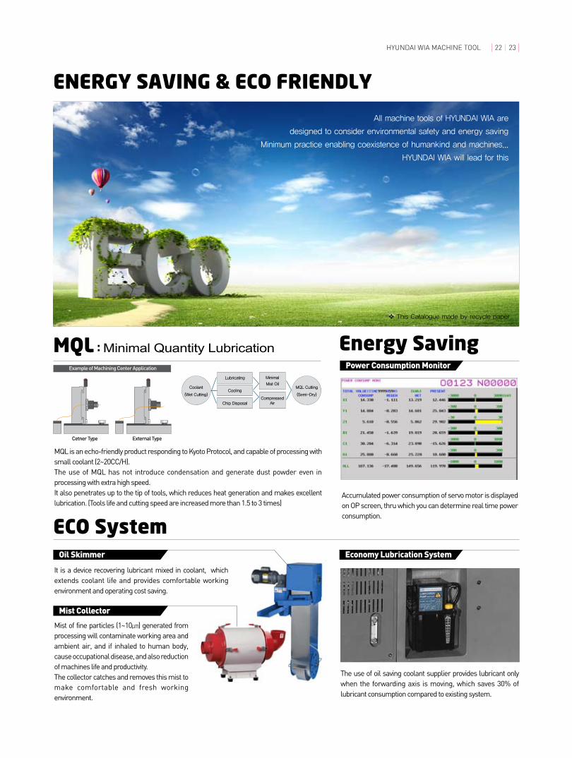
MQL is an echo-friendly product responding to Kyoto Protocol, and capable of processing with small coolant (2~20CC/H).The use of MQL has not introduce condensation and generate dust powder even in processing with extra high speed.It also penetrates up to the tip of tools, which reduces heat generation and makes excellent lubrication. (Tools life and cutting speed are increased more than 1.5 to 3 times)
The use of oil saving coolant supplier provides lubricant only when the forwarding axis is moving, which saves 30% of lubricant consumption compared to existing system.
Power Consumption Monitor
Accumulated power consumption of servo motor is displayed on OP screen, thru which you can determine real time power consumption.
ECO System
Coolant
(wet Cutting)
MQl Cutting
(Semi-Dry)
lubricating Minimal
Mist Oil
Compressed Air
Cooling
Chip Disposal
It is a device recovering lubricant mixed in coolant, which extends coolant life and provides comfortable working environment and operating cost saving.
Mist of fine particles (1~10㎛) generated from processing will contaminate working area and ambient air, and if inhaled to human body, cause occupational disease, and also reduction of machines life and productivity. The collector catches and removes this mist to make comfortable and fresh working environment.
❖ This Catalogue made by recycle paper