high precision horizontal machining center · presenting the ideal machining center. it’s been 50...
TRANSCRIPT

High Precision Horizontal Machining Center

Presenting the ideal machining center.It’s been 50 years since the birth of the machining center. As performance reaches
maturity, we at Mori Seiki decided to wipe the slate clean and take a completely fresh
look at machine tool design. The result was “Driven at the Center of Gravity,” a
method to minimize the vibration of moving parts. The perfect “Driven at the Center
of Gravity” system was made possible for the NH4000 DCG by achieving the ideal
form of the machining center. It fuses high speed and high quality at a top level.
However, the machining center still has room to grow. This is proven by how much of
the future is packed into this machine.
High Precision Horizontal Machining Center
2
B-axisY-axis
Z-axis
X-axis
B-axisY-axis
Z-axis
X-axis
D r i v e n a t t h e C e n t e r o f G r a v i t y
3
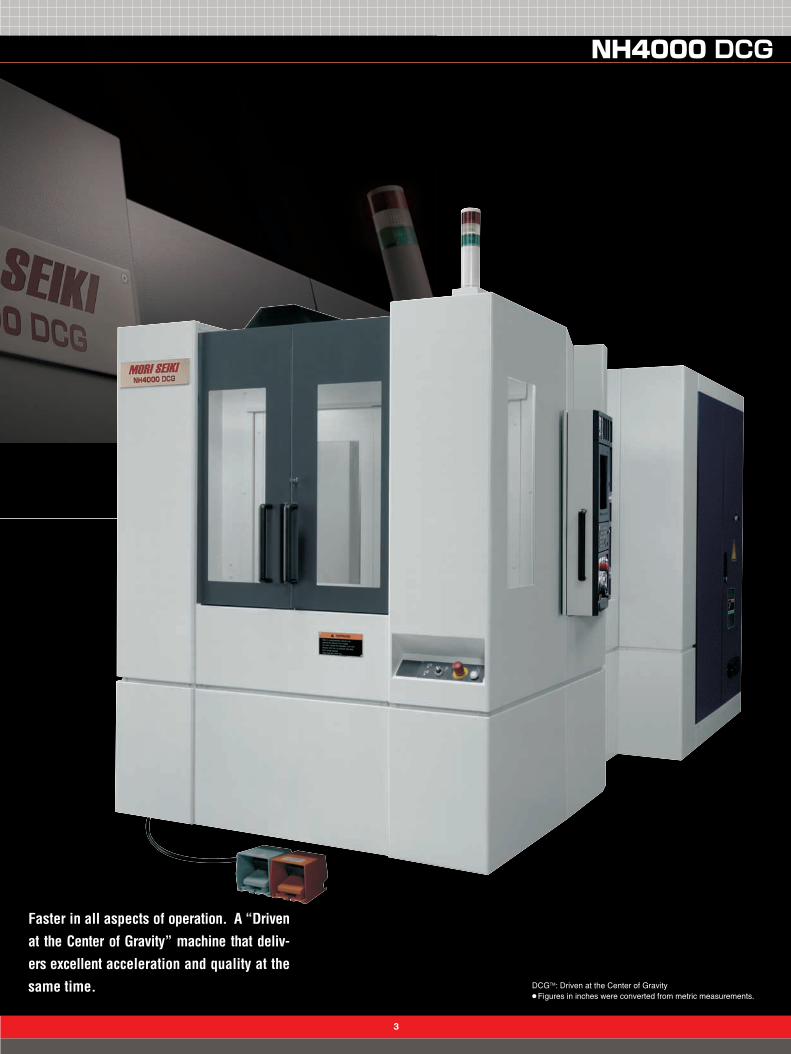
DCGTM: Driven at the Center of Gravity●Figures in inches were converted from metric measurements.
Faster in all aspects of operation. A “Drivenat the Center of Gravity” machine that deliv-ers excellent acceleration and quality at thesame time.
B-axisY-axis
Z-axis
X-axis

4
DCGTM: Driven at the Center of Gravity
This is the Mori Seiki approach to“Driven at the Center of Gravity”. ~“Dr iven a t t he Cen te r o f Grav i ty”
The s to ry beh ind i t s deve lopmen t and the advan tages i t can b r ing you~
This is the Mori Seiki approach to“Driven at the Center of Gravity”. ~“Dr iven a t t he Cen te r o f Grav i ty”
The s to ry beh ind i t s deve lopmen t and the advan tages i t can b r ing you~
DCGTM: Driven at the Center of Gravity
1: A breakthrough in high-speed, high-precisionmachining technology after 15 years.
Starting in the mid-1980s, machine after machine was producedfor high speed and high precision. The biggest challenges duringthe first 10 years were size and speed and spindle motors,developing the technology to deal with the resultant heat,designing machines to match fast NC devices, and other areas.The results were quite impressive. However, the past 5 yearshave seen a loss of direction in the search for technologies toincrease speed and precision. Machining time was only slightlyreduced by increasing speed, but on the other hand speed hadto be sacrificed for higher precision or surface quality.
In comes “Driven at the Center of Gravity” – a technologycreated by approaching the actual movement dynamics of themachine. Any machine tool engineer worth his salt knows it’salways better to push against the center of gravity. Few engineersthought about why this is so important.
At Mori Seiki, we believe this technology will make possiblethe most fundamental improvements in machining time, precision,surface quality, and tool life. This principle is common to allmachine tools in which the tool and the workpiece move relativelyto each other, not just machining centers.
Mori Seiki machines using the “Driven at the Center of Gravity”principle can move as instructed, accurately and with ease.
2: Driven at the Center of Gravity
The “Driven at the Center of Gravity” principle reducesmachining time, improves contouring precision, and deliversbetter surface quality. Everyone knows you have to pushsomething at its center of gravity; otherwise it will spin andbecome unstable. “So push it at the center” – that, in so manywords, is the “Driven at the Center of Gravity” principle. (Fig. 1)
Machine tools use ball screws and linear motors to movetools and workpieces. If they are pushed at their center ofgravity, moving them poses no problem, although, sometimesthis is not true.
Why? Take, for example, the axis that moves the spindle upand down in a vertical machining center. The center of gravityof the spindle is the center of the spindle itself, but you cannotput a ball screw there.
On the other hand, the center of gravity of the axis whichmoves the table back and forth in a horizontal machining centeris somewhere just above the surface of the table when workingwith a heavy workpiece. In other words, the table’s center ofgravity is inside the workpiece. There is no way you can get aball screw in there, either.
The solution? At Mori Seiki, we had the idea to enclose thecenter of gravity with two drive points on either side. The lineconnecting the middle of two ball screws would have to passthrough the center of gravity of the object being moved. (Fig. 2)
[The “Driven at the Center of Gravity” principle]
If the edge of the part is beingpushed, balance is lost andvibration is created.
If the center of gravity ispushed, the part moves straightwithout any vibration.
Machine tools hold objectsabove the center of gravity,making it impossible to pushthem at the center of gravity.
However, if the edges on otherside of the center of gravity arepushed, the object movesstraight.
(Fig. 1) (Fig. 2)

5
3: Vibration during axis travel
So what, specifically, are the advantages of the “Driven at theCenter of Gravity” innovation? In a word (or two): less vibration.The graph (Fig. 3) compares vibration in our “Driven at theCenter of Gravity” machines and standard machines.■ shows the amount of vibration during travel in the
NV4000 DCG without the “Driven at the Center of Gravity”principle applied. ■ shows the same situation, but with theprinciple applied. The results are dramatic and clear.
4: What’s so bad about vibration?
This graph (Fig. 4) shows a time-based representation ofvibration. Note how the “Driven at the Center of Gravity”machine stops the vibration almost right away, while the ordinarymachine continues to vibrate long after.
At the edge of the vibrating machine, a tool and a workpieceare attached. Obviously, the vibration will adversely affect thequality of the machined surface.
Additionally, if the tool enters the workpiece while both arevibrating, the tool tip will wear down. Vibration is the naturalenemy of tool life.
There is an even graver problem. When there is vibration,the NC device reacts to it by deviating from the instructionsand attempts to correct it by moving the feed motor. This, ofcourse, results in even more vibration in most cases.
Engineers are familiar with this phenomenon, so to counteractit, they adjust the NC device to react with less sensitivity. Inother words, they make the NC device ignore minor discrepancies.As a result, operating precision plummets or speed is sacrificed.Therefore, vibration could be called the natural enemy of precision and machining time.
The vibration occurring after the spindle is raised and lowered, then stopped.
■ Non-“Driven at the Center of Gravity” �■ “Driven at the Center of Gravity”
Amou
nt o
f vib
ratio
n (μ
m)
18.07
0X Y Z
2468101214161820
0.59
7.20
11.22
1.380.13
─ Non-“Driven at the Center of Gravity”─ Driven at the Center of Gravity
Time (sec.)
100 % forward feed stopped in Z-axis direction
Vibr
atio
n am
plitu
de (μm)
-10-8-6-4-20246810
0.4 0.45 0.5 0.55 0.6
(Fig. 3)
(Fig. 4)
The vibration occurring after the spindle is raised and lowered, then stopped.
■ Non-“Driven at the Center of Gravity” �■ Non-“Driven at the Center of Gravity” plus linear motor■ Driven at the Center of Gravity■ “Driven at the Center of Gravity” plus linear motor
0X Y Z
2468101214161820
Amou
nt o
f vib
ratio
n (μ
m)
18.0716.82
0.13��
0.13��
7.20��7.21��
1.38��1.13��
11.22 9.64
0.59��0.34��
(Fig. 5)
5: Why linear motors?
Linear motors are touted as the end-all be-all when discussingdynamic characteristics of machine tools, supposedly because theball screw acts as a torsion bar. Is this really the case when com-pared with the “Driven at the Center of Gravity” principle? Thegraph (Fig. 5) adds a linear motor to the previous graph (Fig. 3).■ is a non-“Driven at the Center of Gravity” machine with
a linear motor and ■ is a “Driven at the Center of Gravity”machine with a linear motor. The effects of the linear motorare negligible compared with those of the “Driven at the Centerof Gravity” design.
[Minimize residual vibration of the tool tip]
《with DCGTM》
《without DCGTM》

6
7: Reduction of machining time
The “Driven at the Center of Gravity” innovation is veryuseful for reducing machining time.
Machines that are “Driven at the Center of Gravity” producelittle vibration at the start of acceleration, which means theycan accelerate at full force right from the start. Machinesnot endowed with this innovative technology, however,must apply accelerating force gradually, for fear of creatingtoo much vibration when starting to accelerate.
This graph (Fig. 7) shows non-“Driven at the Center ofGravity” machines on top and “Driven at the Center ofGravity” machines on bottom. It clearly shows the differencein time to maximum acceleration when starting to accelerate,indicated by the blue curve, creates a very large gap in thetime it takes to reach maximum speed.
Time
Spe
ed
“Driven at the Center of Gravity” effect
Previous model
DCGTM
(Fig. 7)
8: Gain
Is the “Driven at the Center of Gravity” innovation necessaryon all axes? The point of using “Driven at the Center ofGravity” technology is to reduce the amount vibration causedwhen an axis begins moving. This vibration is caused whenthe location being pushed and the center of gravity of theobject being moved are not the same. If the difference isminor, then this innovative technology is not needed.That’s where gain comes into play, so let’s take a closer look.
Gain is a parameter used to control the accuracy of amachine’s movement. The greater the gain, the more amachine tries to move accurately in accordance with itscontrol instructions. Some machines cannot follow thoseinstructions faithfully, causing a great deal of variation inthe movement.
Machine designers know you can set the gain high on agood machine but cannot on a bad machine, so they try tofind ways to raise the gain. The size of the gain can varywithin the same machine, depending on the axis involved.Some axes can handle high gain, and some cannot. AtMori Seiki, we think this depends on the distance betweenthe center of gravity and the drive point.
Therefore, it is not unreasonable to say there is little needto add ball screws or use careful axis-center drive on axeswhen distance is short and gain can be set high.
《with DCGTM》 《without DCGTM》
《with DCGTM》 《without DCGTM》
6: Improving machined surface quality
The “Driven at the Center of Gravity” design is said to be effectivein improving machined surface quality. Let’s examine this claim.
Machining of curved surfaces is a major part of die and moldmachining. The curved surface can be looked at as a successionof subtle polygonal lines – the direction of travel changes ever soslightly at each corner along the line. In order to make thesechanges without losing speed, powerful acceleration is needed,even if the changes in direction are only slight.
At each point where acceleration starts, rotational vibration pro-portional to the distance between the drive point and the center ofgravity occurs. This is particularly noticeable when the machiningpoint descends down the side of a pocket, reaches the bottom, andthen suddenly changes direction. The unstable lines in Picture aretraces of a sudden change in direction by the machining point inan ordinary machine.
However, the “Driven at the Center of Gravity” technology getsto the heart of the cause of deterioration in the quality of themachined surface.
Another example of this type of sudden change in direction is thecutback during round cutting. This problem occurs when the toolcuts into the workpiece at 0°, 90°, 180°, and 270°. Roundness isvery important when replacing boring with contouring using anend-mill that easily makes diameter correction. The “Driven at theCenter of Gravity” technology improves roundness, too. (Fig. 6)

(図7)
7
[Dynamic analysis]
Real cutting simulation using dynamic analysis.
900
mm
(35.
4 in
.)
630630 mm (24.8 in.)Max. workpiece swing diameter
630 mm (24.8 in.)Max. workpiece swing diameter
Max
. wor
kpie
ce h
eigh
t
[Machine size]
The NH4000 DCG has the smallest depth and width in its class due to theuse of a pocket-type center conveyor. We have also used a space-savingtool magazine that barely increases the area of installation, even if thenumber of tools is increased.
The world’s smallest depth dimension
3,755 mm (147.8 in.)
The world’s smallest
width dimension2,300 mm
(90.6 in.)
2,61
0 m
m(1
02.8
in.)
Previous model A Previous model B
Width mm (in.)Depth mm (in.)Height mm (in.)Volume m3 (ft3)
Item2,905 (114.3)4,357 (171.5)2,587 (101.9)32.74 (1156.4)
Company
2,530 (99.6)3,765 (148.2)2,700 (106.3)25.72 (908.4)
2,524 (99.4)4,015 (158.1)2,517 (99.1)25.51 (901.0)
NH4000 DCG2,300 (90.6)3,755 (147.8)2,610 (102.8)22.54 (796.1)
Size comparison with previous Mori Seiki models
[NH4000 DCG Design]
X-axis twin drive
Column
Saddle
X-axis twin drive system
The X-axis twin drive system has been employed to enableuse of a gravity drive. We have achieved a stable machinedesign using box-in-a-box technology.
X-axis virtual drive position
Spindle deceleration time(14,000→0 min-1)
1.35 sec.
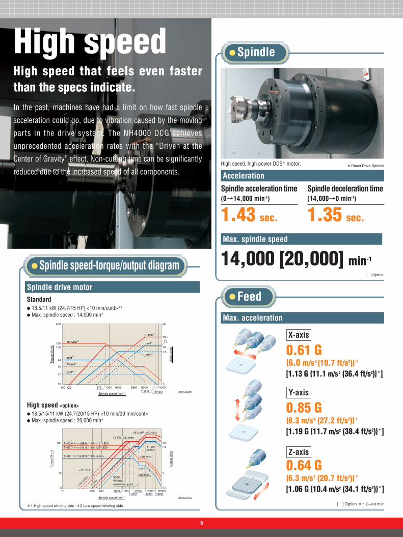
High speedHigh speed that feels even fasterthan the specs indicate.In the past, machines have had a limit on how fast spindle
acceleration could go, due to vibration caused by the moving
parts in the drive system. The NH4000 DCG achieves
unprecedented acceleration rates with the “Driven at the
Center of Gravity” effect. Non-cutting time can be significantly
reduced due to the increased speed of all components.High speed, high power DDS* motor. *Direct Drive Spindle
Spindle acceleration time(0→14,000 min-1)
1.43 sec.
Acceleration
Max. spindle speed
Q43348A02
14,000 [20,000] min-1
8
[ ] Option
Spindle drive motor
Spindle
Spindle speed-torque/output diagram
14000100 120 875 1000 1600 3567 600010000
1
7.5
10
1118.5
40400
120100
44
29
17
10
12000
cont*2
15 min*1
10 min*1
cont*1
cont*2
cont*1
10 %ED*2
Spindle speed (min-1)
Out
put (
kW)
Tor
que
(N・
m)
*1 High-speed winding side *2 Low-speed winding side
Max. acceleration
Feed
[ ] Option *1 G=9.8 m/s2
X-axis
0.61 G {6.0 m/s2 (19.7 ft/s2)}*
[1.13 G {11.1 m/s 2 (36.4 ft/s2)}*]
0.64 G {6.3 m/s2 (20.7 ft/s2)}*
[1.06 G {10.4 m/s2 (34.1 ft/s2)}*]
0.85 G {8.3 m/s2 (27.2 ft/s2)}*
[1.19 G {11.7 m/s2 (38.4 ft/s2)}*]
Y-axis
Z-axis
Q43322A02
103
10
100
200100 1000 1300 2300 10000 200000.3
1
107.5
60001760 13000
T=59.7 N・m (44.0 ft・lbf) <25%ED>
<25 %ED>
T=80.8 N・m (59.6 ft・lbf) <10 %ED>
<10
%ED>
<10 min>
<cont>
T=31.1 N・m (22.9 ft・lbf) <cont>
15 kW <30 min>
18.5 kW <10 min>
11 kW<cont>
3568�Winding switchover point
<30 min>
<con
t>
Tor
que
(N・
m)
Out
put (
kW)
Spindle speed (min-1)
Standard● 18.5/11 kW (24.7/15 HP) <10 min/cont>*1
● Max. spindle speed : 14,000 min-1
High speed <option>● 18.5/15/11 kW (24.7/20/15 HP) <10 min/30 min/cont>● Max. spindle speed : 20,000 min-1

9
Rapid traverse rate
50 m/min(1,968.5 ipm)<X-/Y-/Z-axis>
2-station turn-type APC
Table
Tool changing time
Pallet changingtime
6 sec.
Table indexing time*2*3
1.3 sec.[0.5 sec.*1]
1˚[0.001˚*1]
Rapid traverse rate
2.8 sec.(chip-to-chip)
0.9 sec.(tool-to-tool)
The X-, Y-, and Z-axis have ball bearing linearguides, ensuring high-speed operation.
Minimum table indexing angle
ATC
APC, Table
100 min-1
Maximum rotational speed of the table
0.43 sec.
22 min-1
0.85 sec.
Indexing time*3
[ ] Option *1 Full 4th axis rotary table. *2 Including clamping and unclamping time. *3 90°
Synchronized tapping capability*1*2
2,800 min-1
23 mm (0.9 in.)*3
23 mm (0.9 in.)*323 mm (0.9 in.)*3
4,000 min-14,000 min-12,800 min-1
23 mm (0.9 in.)*323 mm (0.9 in.)*3
2,800 min-1
23 mm (0.9 in.)*3
4,000 min-1
Previous model NH4000 DCG
1.4times faster
Compared againstprevious model
4.5 times faster
Compared againstprevious model
Compared to previous machines, the improved spindle and axis acceleration allows tapping at higher speeds.
B-axis indexing table <the meaning of user-defined in unclear>Changing from the worm gear system used on previous models to a direct drive servo (DDS)has made indexing much faster.
*1 Max. spindle speed at speed of 6,000 min-1 *2 In actual operation, the spindle may fail to reach the specified speed depending on thedistance from the operation start point to the workpiece.*3 For cutting depth=3×tap diameter+5 mm (0.2 in.)
Reduced by 1/2
Compared againstprevious model
Previous model NH4000 DCG
Synchronized tapping
OP
OP : Option

10
High precision The ultimate in surface quality thanks to the“Driven at theCenter of Gravity” design.Another advantage of the “Driven at the Center of Gravity” design is the improved surface quality.
Using a twin drive on the NH4000 DCG’s X-axis helps control vibration. We are capable of having
smoother machined surfaces than ever before.
Sample workpieces
Comparison of tool wear
Cutting distance (m)
Bla
de ti
p w
ear
(mm
)
NH4000 DCGPrevious model
φ 8 mm Drill Flank wear
0 1.4 2.8 4.2 5.6 7.0 8.4 9.8 11.2 12.6 14.0 15.40
0.1
0.2
0.3
Cutting distance (m)
Bla
de ti
p w
ear
(mm
)
φ 16 mm End mill Flank wear
0 3.0 6.0 9.0 12.0 15.0 18.0 21.0 24.0 27.0 30.0 33.00
0.05
0.10
0.15
0.20
0.25
NH4000 DCGPrevious model
Minimizing tool tip vibration prevents wear and extends tool life.

11
High precision
Pallet clamp system
Spindle lubrication
A flange contact taper cone with excellent clamping power and high pallet-positioning precision.
Ball screw coolingBall screw axle coolant which also flows through the support bearings.
By creating a design that minimizes vibration, we have improved contouring precision and machined surface quality. This is the “Driven at the Center of Gravity” advantage.
Direct scale feedback
This prevents heat from the motor from transferring to the ball screws.
90°�
270°�
180°�
5 μm
Aluminum
Filter: 50
Material <JIS>
Tool
Spindle speedFeedrate
A5052<outer diameter:100 mm (4.0 in.)>A 16 mm (A 0.6 in.)End mill<4 blades>8,000 min-1
2,000 mm/min(78.7 ipm)
:
:
::
1.8μmX The cutting test results indicated in this catalog are provided as an example. The results indicated in this catalog may not be obtained due to differences in cutting conditions and environmental conditions during measurement.
OP● Oil feed is kept to a minimum to reduce frictional loss.● Air purge prevents dust infiltration.
OP : Option
Dynamic Thermal Displacement ControlMinimizes thermal displacement of the spindle.Processing accuracy is stable and can be maintained even over long periods of use.
29272523211917
Time (hour)
Dis
plac
emen
t (μ
m)
Am
bien
t tem
pera
ture
(℃)
Displacement tested under the circumstance when the spindle rotating14,000 min-1 and the ambient temperature is within the range of 8 ℃ (46.4 ˚F)
Spindle thermal displacement(temperature compensation+ambient temperature compensation)�
0 2 4 6 8 10 12 14
X-axis
Y-axis
Z-axis
Ambienttemperature
3020100
-10-20-30
Y-axis: 7 μm� X-axis: 6 μm�
Z-axis: 5 μm�
Roundness
Servo motor Ball screw
Cooling oil is circulated to counterthermal displacement.
Constrained face
The absolute positioning optical scale demonstratesunequalled positioning accuracy and can be used forthe X, Y, and Z axes.
The machining area
Inverter-typeoil cooler
Oil-air lubrication
Oil jacket cooling
Oil circulated through a jacket surrounding the spindle minimizes thermal displacement.
X-/Y-/Z-axis
Cooling oil
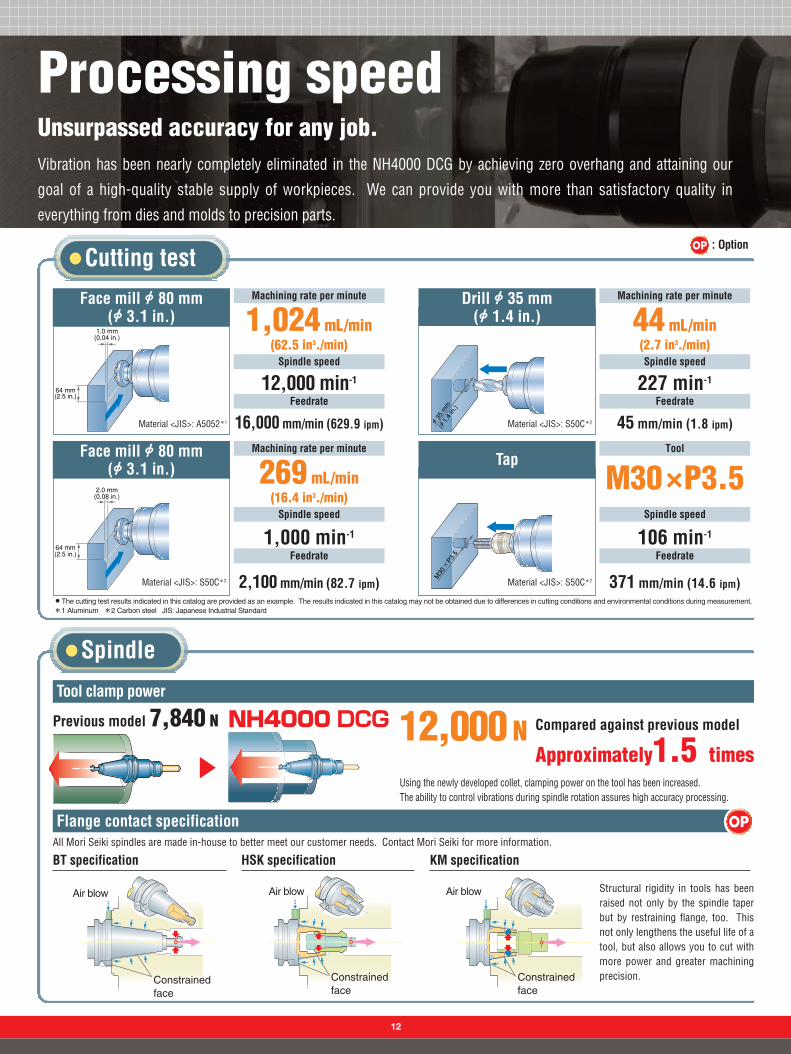
Cutting test
Processing speedUnsurpassed accuracy for any job.Vibration has been nearly completely eliminated in the NH4000 DCG by achieving zero overhang and attaining our
goal of a high-quality stable supply of workpieces. We can provide you with more than satisfactory quality in
everything from dies and molds to precision parts.
Spindle
64 mm�(2.5 in.)
1.0 mm�(0.04 in.)
Face mill B 80 mm(B 3.1 in.)
Material <JIS>: A5052*1
Machining rate per minute
Spindle speed
12,000 min-1
Feedrate
16,000 mm/min (629.9 ipm)
1,024 mL/min (62.5 in3./min)
A 35 mm�
(A 1.4 in.)
Drill B 35 mm(B 1.4 in.)
Material <JIS>: S50C*2
Machining rate per minute
Spindle speed
227 min-1
Feedrate
45 mm/min (1.8 ipm)
44 mL/min(2.7 in3./min)
64 mm�(2.5 in.)
2.0 mm�(0.08 in.)
Face mill B 80 mm(B 3.1 in.)
Material <JIS>: S50C*2
Machining rate per minute
Spindle speed
1,000 min-1
Feedrate
2,100 mm/min (82.7 ipm)
269 mL/min(16.4 in3./min)
M30 × P3.5
Tap
Material <JIS>: S50C*2
Tool
Spindle speed
106 min-1
Feedrate
371 mm/min (14.6 ipm)
M30×P3.5
X The cutting test results indicated in this catalog are provided as an example. The results indicated in this catalog may not be obtained due to differences in cutting conditions and environmental conditions during measurement.*1 Aluminum *2 Carbon steel JIS: Japanese Industrial Standard
Tool clamp power
Flange contact specification OP
NH4000 DCGPrevious model 7,840 N 12,000 N Compared against previous model
Approximately1.5 timesUsing the newly developed collet, clamping power on the tool has been increased. The ability to control vibrations during spindle rotation assures high accuracy processing.
BT specification HSK specificationAll Mori Seiki spindles are made in-house to better meet our customer needs. Contact Mori Seiki for more information.
KM specification
Structural rigidity in tools has beenraised not only by the spindle taperbut by restraining flange, too. Thisnot only lengthens the useful life of atool, but also allows you to cut withmore power and greater machiningprecision.
Air blow
Constrainedface
Air blow Air blow
Constrainedface
Constrainedface
12
OP : Option
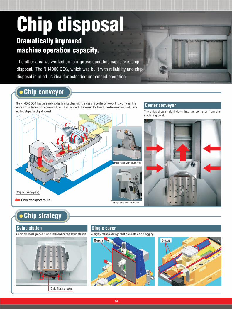
Setup station Single cover
Chip flush groove
Center conveyor
A chip disposal groove is also included on the setup station.
The chips drop straight down into the conveyor from themachining point.
A highly reliable design that prevents chip clogging.
Chip disposalDramatically improvedmachine operation capacity.The other area we worked on to improve operating capacity is chip
disposal. The NH4000 DCG, which was built with reliability and chip
disposal in mind, is ideal for extended unmanned operation.
The NH4000 DCG has the smallest depth in its class with the use of a center conveyor that combines theinside and outside chip conveyors. It also has the merit of allowing the tank to be deepened without creat-ing two steps for chip disposal.
Chip transport route
Chip conveyor
Chip strategy
Chip bucket (option)
13
Scraper type with drum filter
Hinge type with drum filter
X-axis Z-axis

14
ProductivitySee a difference in profit when you reduceyour non-cutting time.The NH4000 DCG was designed to reduce your non-cutting time to
the limit. Let’s take a look at how much a reduction of non-cutting
time can actually affect machining time, production volume, and prof-
its, compared to previous machines.
Data for comparison
[ ] Option
Max. spindle speed12,000 [20,000] min-1
Rapid traverse rateX-, Y-, Z-axis: 42 [60] m/min
(1,653.5 [2,362.2] ipm)Tool changing time (chip-to-chip)3.7 sec.
Max. spindle speed7,000 [10,000] min-1
Rapid traverse rateX-, Y-, Z-axis: 20 m/min
(787.4 ipm)Tool changing time (chip-to-chip)4.6 sec.
Max. spindle speed14,000 [20,000] min-1
Rapid traverse rateX-, Y-, Z-axis: 50 m/min
(1,968.5 ipm)Tool changing time (chip-to-chip)2.8 sec.
(Manufacturing period: 1988 yearー) (Manufacturing period: 1996 yearー)

15
23 pcs.27 pcs.
Productivity17.4 %UPProductivity17.4 %UP
Prod
uctio
n vo
lum
e (p
cs./d
ay)
0
10
20
30
Cycle time (sec.)0 500 1000 1100
Cycle time 1,059 sec.
Cycle time 897 sec.Cycle time 897 sec.
162 sec.Reduced by15.3 %
162 sec.Reduced by15.3 %
Comparison of production volume and sales
4 pcs. per day 20 USD/EUR per day
Running time (one day) : 8 hoursN85 %=3,600 sec.N8N0.85=24,480 sec.
Number of days operating in 1 year : 21 daysN12 months=252 daysProduction volume per day (pcs./day): 24,480 sec.÷Cycle time (sec.)
1st year 2nd year 3rd year 4th year 5th year
34,020
68,040
102,060102,060
136,080
170,100170,100
34,020
68,040
102,060
136,080
170,100
28,980
57,960
115,920
86,940
144,900
5,04010,080
20,16015,120
25,2005-year sales simulation■
■
12 pcs.Productivity125 %UPProductivity125 %UP
Prod
uctio
n vo
lum
e (p
cs./d
ay)
0
10
20
30 27 pcs.
Comparison of production volume and sales
15 pcs. per day 75 USD/EUR per day
Running time (one day) : 8 hoursN85 %=3,600 sec.N8N0.85=24,480 sec.
Number of days operating in 1 year : 21 daysN12 months=252 daysProduction volume per day (pcs./day): 24,480 sec.÷Cycle time (sec.)
1st year 2nd year 3rd year 4th year 5th year
34,020
68,040
102,060
136,080
170,100170,100
34,020
68,040
102,060
136,080
170,100
15,12030,240
60,48045,360
75,60018,90037,800
75,60056,700
94,5005-year sales simulation■
■
Cycle time comparison
Cycle time comparison
Comparison of production volume and sales (5 USD/EUR per work)
Comparison of production volume and sales (5 USD/EUR per work)
9 toolsNumber of tools used
●When machining 2 kinds of workpieces at the same time.
Material <JIS>:A5052(Aluminum)
JIS: Japanese Industrial Standard
9 toolsNumber of tools used
●When machining 2 kinds of workpieces at the same time.
Material <JIS>:A5052(Aluminum)
Unit: USD/EUR
Unit: USD/EUR
Cycle time (sec.)
Cycle time 1,989 sec.
0 1000 2000
Cycle time 897 sec.Cycle time 897 sec.
1,092 sec.Reduced by54.9 %
1,092 sec.Reduced by54.9 %
Comparison with MH-400
Comparison with SH-400

16
MaintenanceMaintenance has beenmade extremely easy.MTTR is an index that rates how easy it is to maintain a
machine. The NH4000 DCG is extremely easy to maintain, since
there are design concepts incorporated throughout the
machine to make maintenance easy and quick-important
factors in reducing downtime.
MTTR:Mean Time To Repair
Press the detail button on the MAPPSⅡ message screen to displaydetailed information about the alarm. Press the e-mail send button tonotify the service center of the contents of the current alarm in an e-mail.
MAPPS: Mori Advanced Programming Production SystemIT: Information Technology
* Network devices and an environment for sending e-mail are required.
Plant
Service center
MAPPSⅡ alarm e-mail sending function*
Machine side Machine rear

Centralized layout of devicesControls are on the side panel to facilitate maintenance.
17
Spindle unit
Fewer parts
Spindle unit replacementAdoption of a cartridge design that even includes the backbearings has significantly reduced spindle replacement time.
Compared against previous model
Less 50 %
300 mm(11.8 in.)300 mm(11.8 in.)
A slim electrical cabinet closes the proximity betweenyou and the insides of the machine during maintenance.
Slimmer electrical cabinet
MTTR:Mean Time To Repair
Changing time
90 min.
NH4000 DCGFlange contact taper conePallet clamp
Previous model
A closer lubrication tank
<Including doors>
NH4000 DCGFlange contact taper cone Pallet clamp
Number of parts in the table design
Coupling type pallet clamp
Approx. 30 partsApprox. 30 partsApprox. 60 partsApprox. 60 partsPrevious model

18
Improved convenience
Ceiling tilt
Adjustable operating panel
90˚90˚
A tilted ceiling preventscoolant from drippingonto the operator.
Swinging the operation panel reduces eye strain and improves operability.
OperabilityThorough convenience.The NH4000 DCG has been designed with the operator in mind, as seen by the
labor-saving features throughout the machine.
Magazine
Visibility of the magazine has been improved with the addition of a door with a window.

An oil-bath design hasbeen integrated into theATC unit. Comparedwith conventional oildrip designs, theamount of lubricantused is radically less.
Oil-bath ATC
19
Eco-friendly designA variety of functions reduce the environmental burden.Reducing the strain on the environment has become an important task
facing companies today. The NH4000 DCG has been designed with
environmentally friendly functions to make this task easier. The new
functions focus on reducing lubricant and electricity consumption. This
focus fills customer needs at reduced costs.
Oil-free roller guides A lubricating oil system for the roller guide is installed on both ends of the block.
● Automatic power-off functionIf the keyboard is not touched after a certainamount of time and NC operation is not beingperformed, power is cut off to the servomotor,the spindle, the coolant pump, and the chipconveyor, thereby saving energy.
Lubricant consumption per hour
Previous model24mL/hour
NH4000 DCG 1.67 mL/hour
Energy-saving settings screen
● Automatic machine light functionIf the operating panel is not touched for a certain amount of time, the interior light turns off.This saves energy and lengthens the life of the machine lights.
● Low speed/low acceleration control functionThis function limits the speed and acceleration of the feed axes when manual operations are carried outduring setup with the interlocks released. By adding a restriction on acceleration to the speed restriction,an even greater power saving is achieved.
Reduced consumption of lubricant
Approximately1/15
Reduction in electricity consumption

Fixture supportProposing the right machiningmethods for your needs.At Mori Seiki, it is our goal to offer you “total engineering
solutions,” which means looking at fixtures as a vital part
of the overall system and providing you with the fixtures
and interfaces that fit your needs.
Fixture interface
Hydraulic supply
Compressedair supply
Compressedair supply
Hydraulic supply
Compressedair supply
Compressedair supply
Easily transfer the pallets between the setup station and the work area andavoid external hoses and couplers.
Compressed air is supplied to the setup station. Hydraulic fluid is suppliedto both the setup station and the machining table.● Hydraulic fluid is supplied to the machining table through two ports that diverge from one circuit.
Workpiece clamp detection air port
Extra portUnclamp port
Unclamp port
Clamp port
Clamp port
2
1
2
1
Auto-coupler fixture interface
Check list (for hydraulic/pneumatic fixtures)● Pressure source
HydraulicPneumatic
● Supplied pressure ___MPa
● No. of circuitsHydraulic×__Pneumatic×__For workpiece holding detection×__
● OthersClamp check systemFixture chip washFixture air blow system
OP
20
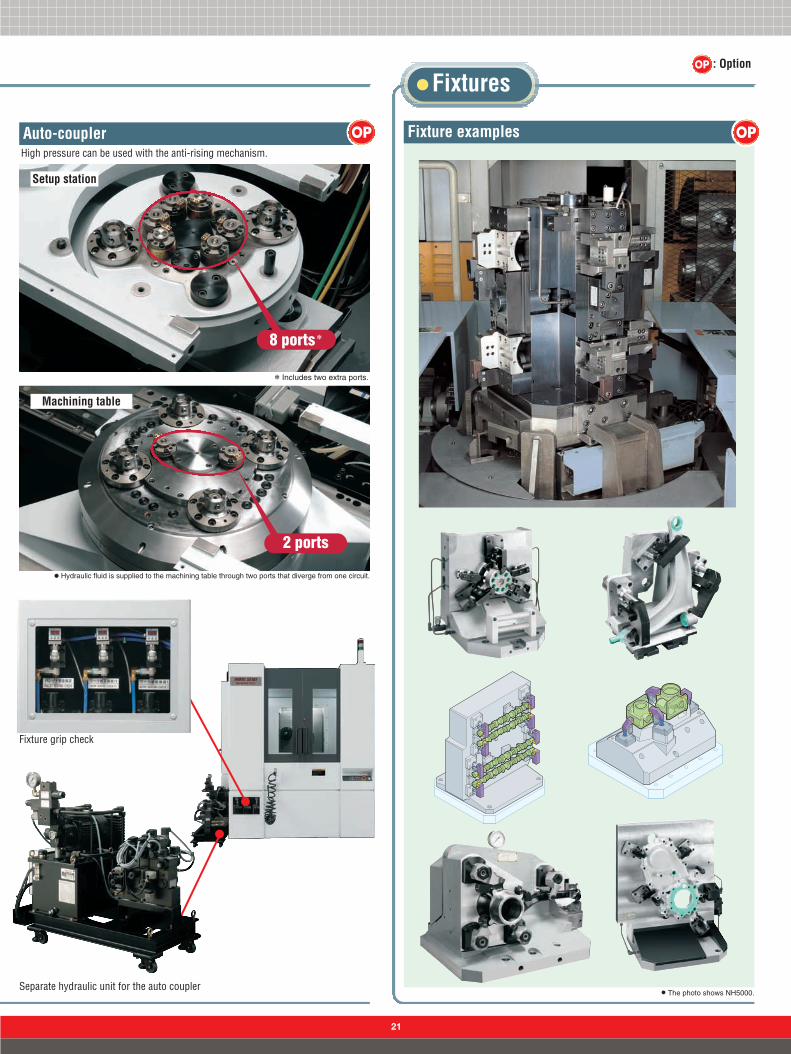
Fixture examplesHigh pressure can be used with the anti-rising mechanism.
● Hydraulic fluid is supplied to the machining table through two ports that diverge from one circuit.
Fixture grip check
Separate hydraulic unit for the auto couplerX The photo shows NH5000.
Auto-coupler
Fixtures
OPOP
Machining table
Setup station
* Includes two extra ports.
8 ports*
2 ports
OP : Option
21

22
Automaticoperation supportThe ideal ultimate solution for your produc-tion system.Long continuous machining, unmanned operation, small-lot,
and varied-item production are all different environments the
NH4000 DCG’s flexible system can work in to greatly improve
productivity.X The photo shows NH5000.
Robot
Gantry-type loader
Robots make workpiece loading and unloading more efficient, improving productivity.
This line-ready mass-production system is completely automated, from materialssupply to ejection of the final product.
CNC Lathe
Workpiece tableStand-alone robot
Chip bucket (option) NH4000 DCG
Gantry-type loader
Workpiece conveyor
Collect-type Chip conveyoroutside machine
NH4000 DCG
OP
OP
Work transfer system
Chip bucket (option)

23
OP : Option
Magazine
APC
3-station turn-type APC
Magazine design which doesnot increase machine width.
Chain-type Rack-type
40-tool*
60-tool*
*Including a dummy tool.
OP
OP
120-tool*
OP
180-tool*
OP
X The photo shows NH6300 DCG.
Built-in 3-station turn-type APCEquipped with a tool magazinethat can hold up to 120 toolsand has a changer option.
Optional coolant gunavailable.
Increases productivity because it is the same compact size as the 2-station APC.

24
A one level CPP with outstanding extensibility.Package systems with rapid set up are available.
System chart
CPP (Carrier Pallet Pool)
X The photo shows NH5000.
■ Horizontalspecifications
■ Vertical specifications
8CPP1871
10CPP11091
12CPP112111
×2-14CPP*
214121
■ CPP system configuration options example (one level of racks)Horizontal specifications
Vertical specifications
6CPP1651
Machine (units)Number of pallets (surfaces)Number of racks (rack)Setup station (units)
7CPP1761
9CPP1981
11CPP111101
5CPP1541
OP
Machine (units)Number of pallets (surfaces)Number of racks (rack)Setup station (units)
1
2
3
4
Pallet racks1
Workpiece transport system2
System construction (one level of racks)
Setup station3
Controller4
X Coolant gun option pictured.
Direction of workpiece transfer
● The illust. shows NH6300.
* Contact Mori Seiki for more information.

25
System construction (two levels of racks)
Example system (layout diagram)
To meet your needs, we offer a variety of systems with various options including a change in the number of pallets and set up. Increasing the number of levels can save space.
Direction of workpiece transfer
LPP (Linear Pallet Pool) OP
X The photo shows NH5000.
Machine (units)Number of pallet racks (rack)Number of pallets (surfaces)Setup station (on machine) (units)Setup station (on opposing side) (units)
LPP-1113121-
LPP-211312-
1
LPP-3222201-
LPP-421412-
1
LPP-5226242-
LPP-621412-
2
LPP-7335322-
LPP-832320-
2
■ LPP system configuration options example
System chart
OP : Option
mm (in.)
● The illust. shows NH6300 DCG.
Machine1
Workpiece transport system3
Setup station2
Pallet racks*4
Controller5
1
3
2
4
5
8000 (315.0)
710(28.0)
2500 (98.4) 3000 (118.1) 2500 (98.4)
5250 (206.7)
750(29.5)
1500 (59.1) 1500 (59.1) 1500 (59.1)
1500 (59.1) 250(9.8)
250(9.8)
750(29.5)
950
( 37.
4)95
0( 3
7.4)
1450
(57
.1)
790(31.1)
572.
5( 2
2.5)
3370
( 132
.7)
5842
.5( 2
30.0
)
LPP-1
710(28.0)
5250 (206.7)
750(29.5)
1500 (59.1) 1500 (59.1) 1500 (59.1)
250(9.8)
250(9.8)
750(29.5)
950
( 37.
4)95
0( 3
7.4)
3370
( 132
.7)
5842
.5( 2
30.0
)
3250 (128.0)
2500 (98.4)
6250 (246.1)
3000 (118.1)
9500 (374.0)
1450
(57
.1)
790(31.1)
572.
5( 2
2.5)
LPP-2
* One tray of four pallets (two racks) can be added on as a single set.

26
System control
CPP (Carrier Pallet Pool)
OP
Automation system to maximize efficiency in a flexible production system.
LPP (Linear Pallet Pool)
●Scheduling ●Management and automatic download of machining programs●Real time pallet information and system status ● Production and error logging ● Intelligent machine usage balance● Intranet web reports ● E-mail/pager notification
System data creation All processes
■ Job detail
■ Job group detail
Simple settings
Makes assembly easier
Processing
■ Pallet registration
■ Schedule
■ Tracking
Quick response
■ Gantt chart
Easy perusal
■ Intranet web reports(option)
Remotechecking
Post-process/Assembly
■ Alarm history
■ Machine history and results
■ Operating result
Easy-to-understandgraphs are displayed
■ E-mail/pager notification (option)
E-mail notification
OP : Option
■ Work number screen.(setup screens for work data)
■ PCMDI menu screen
■ Setup stationPallet call screen
■ Work number (sub-) screen (work number setting screen for empty stations and weekly timer)
■ Pallet data screen (sets whether a pallet is in the machine or not)
X The photo shows NH5000

Coolant
27
Coolant system
Oil mist collectorOil skimmer OP
Misting device
Sensor
Automates measurement of tools and workpieces using a spindle-mounted sensor and automates setting of tool length using a table mounted sensor.
Sensor Receiver
Contact type sensor (spindle)
When sensor is used When sensor is stored
Contact type sensor (table mount sensor)
Coolant gun OP
Use the high-pressure coolant gun to flush the chips from the machine and fixtures.
Center
Air+Oil mist
OP OP
OP : Option
Semi-dry unit OP
Shower coolant
Oil skimmer
Oil separator
OP
Through-spindle coolant systemThe through-spindle coolant system effectively eliminates chips,cooling themachine point, and lengthening the lives of your tools.
Coolant
Coolant
Center
Side
OP
High-pressure coolant system(1.5 MPa <217.5 psi>*1/3.5 MPa <507.5 psi>*1/
6.0 MPa <870 psi>*1/7.0 MPa <1,015 psi>*2)
Wash away excess chips from the partsand fixture using the directed coolantcoming from seventeen nozzles.
*1 Discharge volume: 30 L/min (7.9 gpm) *2 Discharge volume: 25 L/min (6.6 gpm)
Coolant cooling unit OPMachining accuracy is stabilized by the coolant cooling unitthat controls heat transmission to a workpiece, tool and table.It is especially effective when using oil-soluble coolant. Thecoolant cooling unit with a heater will be customized.

28
MAPPS: Mori Advanced Programming Production System CE marking: a conformance display CE: Communauté Européenne
UL: Underwriters Laboratories Inc IP65: Protection from the body and solid objects. Protection from water entry.● The product names indicated in this catalog are all trademarks or registered trademarks of the individual companies.
for Machining Center
A new high-performance operating system
■ Equipped with an LCD display that has a very wide angle of view● The NH4000 DCG is equipped with a wide-angle 15-inch TFT LCD display.
The pointing device enables accurateand smooth turning during 3-D cutting simulations.
■ Equipped with a pointing device.
Easy-to-use keyboard with a perfectbalance between operation and compactness.
●User memory area
Standard 50 MB <Tape memory length equivalent to 127,000 m (416,687 ft)>
Option 500 MB●3× better CPU performance than previous
models, with 8× larger main memory
■ High reliability supporting a stable performance● A Windows® XP embedded-based high-reliability system
●Meets safety standards in Europe and the US. CE marking and UL approved
●Waterproofed in conformity with IP65 (IEC60529)
●Withstands vibrations of 0.98 m/s2 (38.6 in./s2)
■ Keyboard layout
Equipped with largememory as a standard
feature

29
■ 3-D CAD solid data (Parasolid®*)
The easy CAM solution designed to import3-D solid models and automatically recognize machining shapes.
CAM system for Machining Center
PROGRAMMING
■ Machining simulation
● Users can convert conversational programs made using VEGATM Milling Edition into NC programs.● Cutting conditions can be changed on the MAPPSⅡcontrol.*Parasolid® is a brand name and registered trademark belonging to Electronic Data Systems Corporation.
On-line programming
Powered by Feature Recognition Technology
Save costs
Reduceprogramming time
Conversational automaticprogramming
3-D CAD solid data import
OP
● It is possible to zoom and torotate while simulating it.The display of the tool path ispossible.
■ 3-D cutting simulation ■ Vastly improved automatic programming function
● Programming time is cut by 30 % due to the enhanced G-codeediting function.
● A function for registering tool names has been added to the tooloffset and workpiece offset screens.
● “Undo” function added to recover from mistakes.
■ Improved setup
● The high-speed fixed cycle allows you to make complex programs like pocketing, trochoid cycle, helical hole cycle, high speed side milling cycle, Z feeding groove cycle,elliptical milling cycle, spherical milling cycle and more with a few simple instructions.
■ Complex programs can be done with simple instructions ■ An abundance of maintenance functions
High speed side milling cycle Z feed grooving cycle Trochoid cycle● Equipped with handy new
functions for maintenanceand upkeep.
Limit switch guidance function
Regular maintenancefunction
OP : Option
OP
● Up to 127 islands can bedefined.
●Machining time is greatlyreduced by the optimizedpath generation function foropen pockets.
Island shape, open pocket
OP
30
O
Fixture unclamp 11<hydraulic Max. 7 MPa (1,015 psi)>Fixture-side port: a hole A 9 (A 0.35) or smaller
Fixture clamp 11<hydraulic Max. 7 MPa (1,015 psi)>Fixture-side port: a hole A 9 (A 0.35) or smaller
Fixture clamp 1<hydraulic Max. 7 MPa (1,015 psi)>Fixture-side port: a hole A 9 (A 0.35) or smaller
Workpiece clamp detection air port 1(workpiece clamp detection only available on setup ST side)Fixture-side port: a hole A 9 (A 0.35) or smaller
Fixture unclamp 1<hydraulic Max. 7 MPa (1,015 psi)>Fixture-side port: a hole A 9 (A 0.35) or smaller
Workpiece clamp detection air port 11(workpiece clamp detection only available on setup ST side)Fixture-side port: a hole A 9 (A 0.35) or smaller
400 (15.748)P2
P2
P2
P2
P1
P1
P1
P1
400
(15.
748)
P.C.D. 128 (5
.0)
25 (1.0
)
36 (1.4)
25 (
0.98
4)
50 (2.0
)50 (2.0
)
25(1.0)
18 (
0.70
9)
55 (2.165)
80 (3.1)
18 (0.7)
2 extra ports
1 extra ports
D
D
D
DD
D
D
A
A
B B
A 26 (A 1.024)
A 18 (A 0.709)
C C
D
D
D
DD
D
DD
Fixture
1.8
(0.0
7)10
.2(0
.4)
Fixture-side port: a hole A 9 (A 0.35) or smaller
P11 O-ring
Chamfer C 0.2 (0.008) or lower
A 20 (A 0.8)
0.5
(0.0
20)
30 (
1.18
1)
40 (
1.57
5) 118˚
M16 (1/2-13 UNC)P=2.0 (0.08)Depth=30 (1.2)Lower cut A 14.0 (A 0.6)Depth=45 (1.8)
Details on hole for workpiece tightening screw
(Cross-section B-B)
Details on hole for workpiece attachment bolt
(Cross-section A-A, C-C)
A 15(A 0.6)
44(1.7)
44(1.7)
36 (1.4)16 (0.6)
100(3.9)
100(3.9)
A 9(A 0.35)
25 (
1.0)
14.5
(0.
6)
45°�
45°�
22.5°�D
22.5°�D
45°�
D
45°�
D
D
D
D
45°�
22.5°�22.5°�45°�
36 (
1.4)
55 (2.165)
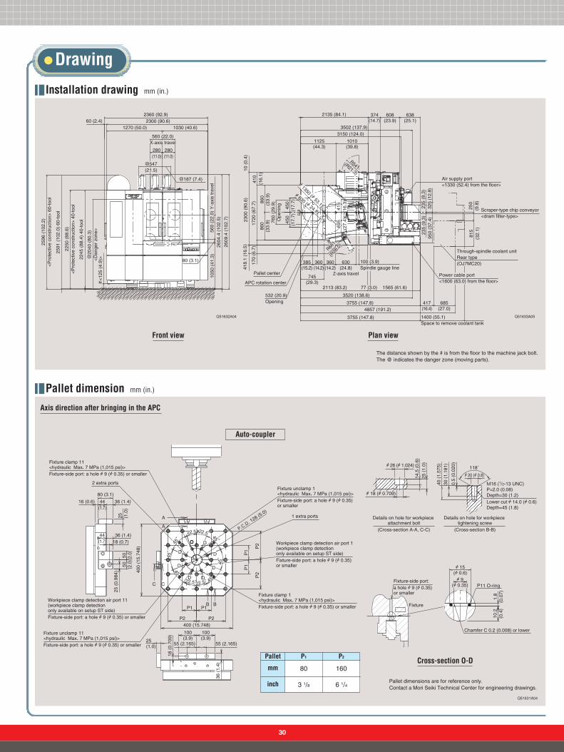
Drawing
Installation drawing mm (in.)
Q51631A04
Pallet dimension mm (in.)
2360 (92.9)2300 (90.6)60 (2.4)
1270 (50.0) 1030 (40.6)
280(11.0)
280(11.0)
@187 (7.4)
560 (22.0)X-axis travel
@547(21.5)
@20
40 (
80.3
)<
Dan
ger
zone
>
2245
(88
.4)
40-t
ool
2250
(88
.6)
<P
rote
ctiv
e co
nstr
uctio
n> 4
0-to
ol
2591
(10
2.0)
60-
tool
2596
(10
2.2)
<P
rote
ctiv
e co
nstr
uctio
n> 6
0-to
ol
#<
125
(4.9
)>
2609
.4 (
102.
7)
2604
.4 (
102.
5)
80 (3.1)
1050
(41
.3)
560
(22.
0) Y
-axi
s tr
avel
1125(44.3)
1010(39.8)
3150 (124.0)
2135 (84.1) 608(23.9)
638(25.1)
250
(9.8
)81
5(3
2.1)
950
(37.
4)23
5 (9
.3)
235
(9.3
)
685(27.0)
417(16.4)
1400 (55.1)Space to remove coolant tank
100 (3.9)Spindle gauge line
630(24.8)
Z-axis travel
3755 (147.8)
4857 (191.2)3755 (147.8)
3520 (138.6)
1565 (61.6)77 (3.0)2113 (83.2)
360(14.2)
745(29.3)
385(15.2)
360(14.2)41
8.1
(16.
5)23
00 (
90.6
)10
(0.
4)
760
(29.
9)O
peni
ng
860
(33.
9)86
0(3
3.9)
410
(16
.1)
1720
(67
.7)
170
(6.7
)
A 1350 (A 53.1)
415
(16.
3)69
5(2
7.4)
R541(R21.3)
R661
(R26
.0)
A 630 (A 24.8)
APC rotation center
Pallet center
532 (20.9)Opening
374(14.7)
3502 (137.9)
325
(12.
8)
Air supply port<1330 (52.4) from the floor>
Scraper-type chip conveyor<dram filter-type>
Through-spindle coolant unitRear type(OJ7MC20)
Power cable port<1600 (63.0) from the floor>
450
(17.
7)45
0(1
7.7)
Front view
Cross-section O-D
Axis direction after bringing in the APC
Auto-coupler
Plan view
The distance shown by the # is from the floor to the machine jack bolt.The @ indicates the danger zone (moving parts).
Q51632A04 Q51633A05
mm
inch
Pallet P1 P2
80 160
6 1/43 1/8Pallet dimensions are for reference only. Contact a Mori Seiki Technical Center for engineering drawings.
31
Drawing
A 630 (A 24.8)Max. size workpiece
560 (22.0) X-axis travel280 (11.0) 280 (11.0)
170 (6.7)*�
900
(35.
4) M
ax. w
orkp
iece
hei
ght
560
(22.
0) Y
-axi
s tr
avel
Touch sensor (table) attachment position
80 (3.1
)
A 630 (A 24.8)Max. size workpiece
100(3.9)
313 (12.3) Y-axis protector353.3 (13.9)
18.5 (0.7) 111.5 (4.4)
900
(35.
4) M
ax. w
orkp
iece
hei
ght
560
(22.
0) Y
-axi
s tr
avel
80 (3.1
)
10 (
0.4)
80 (3.1
)160(6.3)
450 (17.7)
A 500 (A 19.7)Pallet turning diameter
339.6 (13.4) 390.4 (15.4)*�
Sensor cover
A 1
95(A
7.7
)
A 2
50(A
9.8
)A
205
(A 8
.1)
A 2
60(A
10.
2)
630 (24.8) Z-axis travel
20 (0.8)
400×
400
(15.
7×15
.7)
A 5
00 (A
19.
7)P
alle
t tur
ning
dia
met
er
273.5(10.8)223.5(8.8)
456.5 (18.0)
506.5 (19.9)
Q52417A04
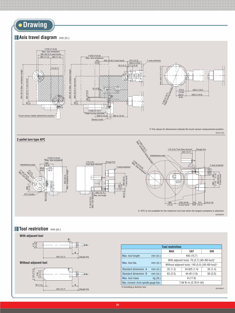
Axis travel diagram mm (in.)
*The values for dimensions indicate the touch sensor measurement position.
Tool restriction mm (in.)
2-pallet turn type APC
Q53308A04
※ ATC is not available for the maximum tool size when the largest workpiece is attached.
Interference area
A 1350 (A 53.1)
Max. w
orkpiece swing diam
eter
A 630 (A 24.8)
Max. size workpiece
115 (4.5) Tool draw amount400 (15.7)
Gauge line
Y-axis protector
560
(22.
0)X
-axi
s tr
avel
280
(11.
0)28
0(1
1.0)
133
(5.2
)13
3(5
.2)
365(14.4)
630 (24.8)Z-axis travel
100(3.9)
313(12.3)
3.8 (0.15)
215(8.5)
210
(8.3
)
Interference area
A 630 (A 24.8)Max. size workpiece480
(18.9)
P.C.D.
400 (15.7)
A 140 (A 5.5)
Max. tool diameter
280
(11.
0)
210(8.3)
20.2(0.8)
900
(35.
4)M
ax. w
orkp
iece
hei
ght
ATC shutter
66.3
(2.
6)
204.9�
(8.1)
177.5�
(7.0)
115 (4.5)Tool draw amount
Gauge line
Y-axis protector
A 1
40 (A
5.5
)M
ax. t
ool d
iam
eter
400 (15.7)Max. tool length
560
(22.
0)Y
-axi
s tr
avel
200
(7.9
)80
(3.1
)
A
A
Gauge line
Gauge line
A B
A B
400 (15.7)
A 1
40 (A
5.5
)
A 8
0(A
3.1
)
30 (1.2)
400 (15.7)
A 7
0(A
2.8
)
Q81069A01
Max. tool length mm (in.)
Max. tool dia. mm (in.)
Standard dimension A mm (in.)
Standard dimension B mm (in.)
Max. tool mass kg (Ib.)
Max. moment <from spindle gauge line>
MAS
400 (15.7)
With adjacent tools: 70 (2.7) [40-/60-tool]*
Without adjacent tools: 140 (5.5) [40-/60-tool]*
8 (17.6)
7.84 N・m (5.78 ft・lbf)
CAT DIN
32 (1.3)
63 (2.5)
34.925 (1.4)
44.45 (1.8)
35 (1.4)
50 (2.0)
Tool restriction
* Including a dummy tool.
With adjacent tool
Without adjacent tool

32
Package Plan
Plan A / Regular parts machining specificationPlan B / Ultra high precision specification
None
Direct scale feedback (X-/Y-/Z-axis)+Dynamic thermal displacement control (Z-axis)
STEP 1 First select the specification.
STEP 2 Next select the package.Table Tool storage capacity Chip conveyor Through-spindle coolant
1˚ Index table Full 4th axis rotary table 40-tool*
Scraper type withdrum filter
(Chip length 50 mm or shorter)
None Interface 1.5 MPa(217.5 psi)60-tool*
Consep 2000Mk2 type
(Chip length 50 mm or longer)
7 MPa(1,015 psi)
PACKAGE 1PACKAGE 2PACKAGE 3PACKAGE 4PACKAGE 5PACKAGE 6PACKAGE 7PACKAGE 8PACKAGE 9PACKAGE 10PACKAGE 11PACKAGE 12PACKAGE 13PACKAGE 14PACKAGE 15PACKAGE 16PACKAGE 17PACKAGE 18PACKAGE 19PACKAGE 20PACKAGE 21PACKAGE 22PACKAGE 23PACKAGE 24PACKAGE 25PACKAGE 26PACKAGE 27PACKAGE 28PACKAGE 29PACKAGE 30PACKAGE 31PACKAGE 32
●
●
●
●
●
●
●
●
●
●
●
●
●
●
●
●
●
●
●
●
●
●
●
●
●
●
●
●
●
●
●
●
●
●
●
●
●
●
●
●
●
●
●
●
●
●
●
●
●
●
●
●
●
●
●
●
●
●
●
●
●
●
●
●
●
●
●
●
●
●
●
●
●
●
●
●
●
●
●
●
●
●
●
●
●
●
●
●
●
●
●
●
●
●
●
●
●
●
●
●
●
●
●
●
●
●
●
●
●
●
●
●
●
●
●
●
●
●
●
●
●
●
●
●
●
●
●
●
* Including a dummy tool.

Handy type
33
Standard & optional features
Contact type sensor (probe sensor)
Contact type sensor <table mount sensor>Contact type sensor <magazine>
Optical type
Inductive type
●
○
○
○
●
○
●
○
○
○
○
○
○
○
○
○
○
○
○
●
●
○
○
○
○
○
○
○
○
○
○
○
○
●: Standard features ○: Options ☆: Please contact Mori Seiki
Max. spindle speed
Inverter-controlled oil coolerFlange contact specification
14,000 min-1
<18.5/11 kW (24.7/15 HP)>*1
20,000 min-1
<18.5/15/11 kW (24.7/20/15 HP)>*2
BT40, HSK A63, KM6350
Spindle
Type of tool shank
Type of retention knob
BT40DIN40CAT40HSK A63KM6350MORI SEIKI 90˚ type45˚60˚DINHSK A63Special <center>
ATC
Tool storage capacity
40-tool <chain-type>60-tool <chain-type>120-tool <chain-type>180-tool <rack-type>
Tool magazine
Side
Center*6
Interface
Coolant
Automatic alignmentAutomatic measurementAutomatic alignmentAutomatic measurementAutomatic tool length measurementAutomatic tool breakage detectionAutomatic tool breakage system
Measurement
Automatic power off systemWeekly timerWork counterTotal counterAutomatic doorManual pulse generatorAutomatic indexing setup stationMulti counterExternal M-code
Operation support device/function
Tool tip air blow system
Chip conveyor (single construction)
Chip bucketCoolant gunOil mist collector
Scraper type (with drum filter)Hinge type (with drum filter)
Chip disposal
○
○
○
○
○
○
○
●
○
○
○
○
○
○
○
○
●
●
○
○
○
☆
*1 10 min/cont*2 10 min/30 min/cont*3 High-pressure coolant system is attached.*4 Discharge volume: 30 L/min (7.9 gpm)*5 Discharge volume: 25 L/min (6.6 gpm)*6 Special retention knobs are required.*7 Oil-hole drill holder available as an option.*8 Recommended when oil-based coolant is used or during unmanned operation.
● The details given above and the specifications are subject to change without notice.● Specifications, accessories, safety device, and function are available upon request.● Some options are not available in particular regions. For details contact Mori Seiki.
Direct scale feedback
Dynamic thermal displacement control
X-axisY-axisZ-axis
Improved accuracy
Full cover
Door interlock system <incl. mechanical lock>
Door interlock systemLow air pressure detecting switchLow hydraulic pressure detecting switchDanger sensing device interface*8
Earth leakage breaker
Safety features
●
●
●
●
○
○
○
●
●
●
●
●
●
●
☆
○
Front doorSetup station doorElectrical cabinet door
Others
3 steps
Built-in worklightLeveling blockHand toolsSignal tower
2, 5, 10
●
○
●
○
○
○
○
○
○
○
○
●
○
○
○
Pallet
1̊ indexing tableFull 4th axis rotary table
Auto-coupler for fixture clamp
Angle plate
Sub-table
Two hydraulic circuits+two clamp circuitsOne hydraulic circuit+one clamp circuitOne-sidedTwo-sidedFour-sidedWithout tapT-slot
Tap <metric, inch>T-slot
Table/Pallet
2-station turn-type APC3-station turn-type APCCPP (carrier pallet pool)LPP (linear pallet pool)
APC
Coolant systemShower coolant
Through-spindle coolant system*3
<1.5 MPa (217.5 psi)*4, 3.5 MPa (507.5 psi)*4,6.0 MPa (870 psi)*4, 7.0 MPa (1,015 psi)*5>
Through-spindle coolant systemOil-hole drill coolant system*7
Oil skimmerOil shot systemOil mist systemCoolant cooling unitCoolant cooling unit <through-spindle coolant>Coolant flow switch <through-spindle coolant>Coolant float switchSemi-dry unit
horizontal, vertical

34
Includes alarm display, I/O signal diagnosis and ladder diagram
NC and PC alarmAbnormal load detection
Stored stroke limit 1Self-diagnosisDoor interlockAlarm history displaySoftware damper
Part program storagePart program editSearch functionNumber of stored programsProgram number/program name
320 m (1,050 ft) <4 kB≒10 m (33 ft) in tape length>Deletion, insertion, and alterationSequence number search, Program number search, Address search125 programs4 digits/48 characters
Mirror imageManual absoluteZ-axis neglectRunning time display/No. of parts displayExpanded tape editing Background editingLoad meter displayClock functionTool length measurementLoad monitoring function C
PC parameter
Screen display
Excepting adaptive control function
Single blockOptional stopOptional block skipDry runMachine lockAuxiliary function lock
Spindle speed function (S function)Spindle speed overrideTool function (T function)Miscellaneous function (M function)High speed M/S/T/B interface
5-digit S code50-120 % (10 % increments)8-digit T code*3
4-digit M code
Controlled axesControlled axesSimultaneously controllable axes
X, Y, Z, BPositioning/linear interpolation/circular interpolation (3/3/2)
Programmable methods
Interpolation
Least input incrementLeast command incrementMax. command valueAbsolute/incremental programmingDecimal point programmingInch/metric conversionTape code
PositioningLinear interpolationCircular interpolationHelical interpolationLinear acceleration/deceleration before cutting feed interpolation
G00G01G02/G03
FeedCutting feedrateDwellPulse handle feedAutomatic acceleration/decelerationRapid traverse rate overrideFeedrate overrideFeedrate override cancelSpindle orientationManual jog feedFeed per minute
1-50,000 mm/min (0.01-1,968.5 ipm)*1
G04Manual pulse generator: 1 unit ×1, ×10, ×100 (per pulse)Linear type (rapid traverse)/Exponential function type (cutting feed)F0 (forward feed stop), 25/100 %0-150 % (10 % increments)M48, M49
0-1,260 mm/min (0-50.0 ipm) <15 steps>
0.001 mm (0.0001 in.)0.001 mm (0.0001 in.)±99,999.999 mm (9,999.9999 in)G90/G91
G20/G21EIA RS244/ISO 840 code automatic discrimination
Programming support functionCircular arc radius commandCanned cycleSub-programCustom macro BExact stop checkExact stop check modeF15 formatSynchronized tapping NC statement output*5
Look-ahead control functionConversational automatic programming
G73, G74, G76, G80-G89, G98, G99Up to 4 nestings
G09G61/G64
Conversational automatic programming function
Safety and maintenance
Program storage and editing
I/O Functions and unitsI/O interfaceTape operation with RS-232-C*2
RS-232-C/PCMCIA (typeⅠ,Ⅱ)
Coordinate systemManual zero returnAutomatic zero return2nd zero return*4
Zero return checkReturn from zero pointAutomatic coordinate system settingCoordinate system settingWork coordinate system selectionLocal coordinate system setting/machine coordinate system
G28G30G27G29
G92G54-G59
G52/53
Operation support functions
STM functions
Operation and displayOperation panel: Display section 15-inch TFT color LCD
Operation support functions
Tool offsetTool length offsetCutter radius offset CNumber of tool offsetsTool offset data memory COffset amount program input
G43, G44, G49G40-G4264 setsD/H code, geometry and wear offset dataG10
Mechanical accuracy compensationBacklash compensationPitch error compensationUni-directional positioningFollow-upRapid traverse/cutting feed backlash compensation
±9,999 pulses
Machine control support functionsAxis interlock By external input: option
Automatic support functionsSkip function G31
*1 For look-ahead control. 5,000 mm/min (196.9 ipm) in non-look-ahead control.Maximum feedrate will vary depending on cutting conditions.
*2 For the machine equipped with APC and if work number search function is required, consultation isnecessary for details.
*3 Conversational automatic programming, Tool file: 4-digit*4 Used with ATC/APC.*5 Output to NC memory is possible. Output to an external device is not possible.*6 The number selectable tool offsets on the tool storage capacity.*7 Max. command value ±9,999.9999 mm (±999.9999 in.)*8 Standard for the machine equipped with sensor.
Additional part program storage capacity <in total>Additional number of stored programs <in total>Additional number of tool offsets <in total>*6
640/1,280/2,560 m (2,100/4,200/8,400 ft)200/400/1,000 programs 99/200/400/499/999 sets
□ Programming resolution multiplied by 1/10 (least input increment 0.0001 mm <0.00001 in.>/least command increment 0.0001 mm <0.00001 in.>)*7
□ Hypothetical axis interpolation □ Polar coordinate interpolation □ NURBS interpolation□ Smooth interpolation □ Cylindrical interpolation □ Exponential function interpolation□ Involute interpolation □ Bell-shaped acceleration/deceleration after cutting feed interpolation□ Whirlpool interpolation □ F1-digit feed (F1ーF9) □ Inverse time feed □ Feed per revolution□ Remote buffer (DNC)*2 □ High-speed remote buffer (A: Binary input, B: NC statement input)*2
□ Data server (ATA card) □ Constant surface speed control □ Tool position offset (G45ーG48)□ 3-D tool offset □ 3-D coordinate conversion□ Additional number of work coordinate systems <in total> (48 sets, 300 sets) □ Floating zero return□ Handle feed interruption □ Program restart □ Sequence number collation and stop□ Addition of optional block skip functions (BDT2 to BDT9) □Machine time stamp function□ Tool escape and return □ Arbitrary angle, chamfer, corner R designation □ Interruption type custom macro□ Programmable mirror image □ Automatic corner override □ Playback□ Additional custom macro common variables <in total> (600 variables) □ Scaling□ Coordinate system rotation □ Polar coordinate command □ Multiple M commands in a block□ AI contour control □ AI nano contour control □ AI high precision contour control□ AInanohigh precision contourcontrol □ Small diameter deep hole drilling cycle □ High-speed skip*8
□ Tool life management □ Additional number of tool life management functions <in total> (512 sets)□ Stored stroke limit 2 □ Rotary table dynamic fixture offset
I95081A06
NC unit specifications (MSX-501)
Standard
Option

35
Feedrate
X-axis travel <longitudinal movement of saddle> mm (in.)
Y-axis travel <vertical movement of spindle head> mm (in.)
Z-axis travel <cross movement of table> mm (in.)
Distance from pallet surface to spindle center mm (in.)
Distance from table center to spindle gauge plane mm (in.)
Pallet working surface mm (in.)
Pallet loading capacity kg (lb.)
Max. workpiece swing diameter mm (in.)
Max. workpiece height mm (in.)
Pallet surface configuration
Table indexing time*2 s
Max. spindle speed*5 min-1
Rapid traverse rate mm/min (ipm)
Jog feedrate mm/min (ipm)
Type of tool shank
Type of retention knob
Tool storage capacity*6
Max. tool diameter <without adjacent tools> mm (in.)
Max. tool length mm (in.)
Max. tool mass kg (lb.)
Max. tool mass moment <from spindle gauge line> N・m (ft・lbf)
Method of tool selection
Tool changing time <tool-to-tool> s
Tool changing time <chip-to-chip> s
Number of pallets
Method of pallet change
Pallet changing time s
Spindle drive motor <10 min/cont> kW (HP)
Feed motor <X/Y/Z/B> kW (HP)
Electrical power supply kVA
Coolant tank capacity L (gal.)
Machine height <from floor> mm (in.)
Floor space mm (in.)
Mass of machine kg (lb.)
ATC
APC
560 (22.0)
560 (22.0)
630 (24.8)
80ー640 (3.1ー25.1)
100ー730 (3.9ー28.7)
400×400 (15.7×15.7)
400 (880) [300 (660)*1)
A 630 (A 24.8) [A 560 (A 22.0)*1]
900 (35.4) [800 (31.5)*1]
M16 (1/2-13 UNC) Tap: 24 Holes. Pitch 80 mm (31/8 in.)
1.3*3 [0.5]*4 (90˚)
14,000 [20,000]
50,000 (1,968.5)
0ー1,260 (0ー50.0) <15 steps>
BT40 [CAT40]
MORI SEIKI 90˚ type
Chain-type: 40 [60] [120] Rack-type: [180]
A 70 (A 2.7) <A 140 (A 5.5)>
400 (15.7)
8 (17.6)
7.84 (5.78)
Fixed address, shorter route access
0.9
2.8
2 [3*1]
Turn-type
6
18.5/11 (24.7/15)*7 [18.5/15/11 (24.7/20/15)*8*9]
1.6×2/4/4/1.2 (2.1×2/5.3/5.3/1.6), 5.3 (7.1)*4
35.2
535 (141.2)
2,610 (102.8)
2,300×3,755 (90.6×147.8)
9,600 (21,120)
Item
Travel
Table
Spindle
Motor
Power sourceTank capacity
Machine size
NH4000 DCG
[ ] Option*1 3-station turn-type APC specification.*2 Including clamping and unclamping time.*3 1˚ indexing.*4 Full 4th axis rotary table.*5 Depending on restrictions imposed by the workpiece clamping device, fixture and tool used, it may not be possible to rotate at the maximum spindle speed. *6 Including a dummy tool. *7 High-speed winding side*8 20,000 min-1
*9 10 min/30 min/cont
Machine specifications
I94025A01

362 Idono-cho, Yamato-Koriyama City, Nara 639-1183, Japan Phone: (0743) 53-1121 <Please note that our head office will be moving to the Nagoya Building on October 1st, 2004.>
362 Idono-cho, Yamato-Koriyama City, Nara 639-1183, Japan Phone: (0743) 53-1121
201 Midai, Iga-cho, Ayama-gun, Mie 519-1414, Japan Phone: (0595) 45-4151
488-19 Suzumi-cho, Funabashi City, Chiba 274-0052, Japan Phone: (047) 410-8800
2-35-16 Meieki, Nakamura-ku, Nagoya City 450-0002, Japan Phone: (052) 587-1811
www.moriseiki.com
Head Office
Nara Campus
Iga Campus
Chiba Campus
Nagoya Building
● The export of this product is subject to an authorization from the government of the exporting country. Check with the government agency for authorization.
NH4000-ED02
0409.CDT.0000
● If you have any questions regarding the content, contact your nearest Mori Seiki dealer or Technical Center.● The information in this catalog is valid as of September 2004. Design and specifications subject to change without notice.●Mori Seiki is not responsible for differences between the information in the catalog and the actual machine.
Created in Japan
Mori Seiki’s Global Service
Service support A rapid and efficient maintenance support system.
JapanJapan
IndonesiaIndonesia
MelbourneMelbourneSydneySydney
TaiwanTaiwanShanghaiShanghai
KoreaKorea
Hong KongHong Kong
BeijingBeijing
ThailandThailand
MalaysiaMalaysia
ShenzhenShenzhenChongqing
TianjinTianjin
UKUK
Open in 2005
HamburgHamburg
SpainSpain
ItalyItalyIstanbulIstanbul
OrléansOrléansMunich
ParisParis
BrazilBrazil
CharlotteCharlotte
New JerseyNew Jersey
ClevelandClevelandBostonBoston
CincinnatiCincinnatiMexicoMexico
Des MoinesDes Moines
IndianapolisIndianapolis
SeattleSeattle
Los AngelesLos Angeles
DetroitDetroit
ChicagoChicagoMilwaukeeStuttgartStuttgart
SingaporeSingapore
DallasDallas
India
DalianDalian
LyonLyon
ToulouseToulouse
OP : Option
Parts LocationsIga Campus
Dallas Technical Center
Stuttgart Technical Center
Singapore Technical Center
Service System
Service Center(Iga, Chiba)
Parts Center
ServicePersonnel
24 hours
24 Shipped within24 hours
24 Delivered within24 hours
365 Operating 365days a year
Factory Service
41 locationsOverseas Dealers
143 suppliers
● Overseas Subsidiaries● Overseas Office●Mori Seiki Mid-American
Sales, Inc.
▲ Overseas Dealers
Overseascountries
● Currently in Japan only.
Accumulation of operating status data
InternetAt the your office and home
Server
At the your factoryAt the your factory
CAPS-NET Global EditionRemote monitoring of your machines over the Internet. With this service it is possible tobuild remote management systems which have great speed and cost performance by usingmachine tools. The Mori Seiki Service Center provides back-up with its rapid service system.
●This system allows you to see the operating statusof your machine tools over the Internet fromwherever you may be in the world
●Regular E-mail notifications are sent to directlyto you with your machine operating status
Low initial investment and running cost
OP