historic structure report...the historic structure report presented here exists in two formats. a...
TRANSCRIPT

C A P E H AT T E R A S N AT I O N A L S E A S H O R E
B O D I E I S L A N DL I G H T H O U S E & O I L H O U S E
HISTORIC STRUCTUREREPORT
Cultural Resources DivisionSoutheast Regional Office
National Park ServiceDecember 2004

Cultural Resources DivisionSoutheast Regional OfficeNational Park Service100 Alabama Street, SWAtlanta, GA 30303404.562.3117
Bodie Island Lighthouse & Oil HouseCape Hatteras National SeashoreManteo, NC 27954
http://www.nps.gov/caha
About the cover: Bodie Island Light Station, HABS # NC-395-5, photographed by Jon Buono; LCS#: 00114.
The historic structure report presented here
exists in two formats. A printed version is
available for study at the park, the Southeast
Regional Office of the National Park Service,
and at a variety of other repositories. For more
widespread access, this historic structure
report also exists in a web- based format
through the web site of the National Park
Service. Please visit www.nps.gov for more
information.

Cape Hatteras National Seashore
Bodie Island Lighthouse and Oil House
Historic Structure Report


Contents
http://crs.sero.nps.gov/historic/hsr/malu
Bodie Island Lighthouse HSR v
List of Figures . . . . . . . . . . . . . . . . . . . . . . . . . . . . . . . . . . . . . . . . . . . . . . . . . . . . . . . . . . . vii
Foreword . . . . . . . . . . . . . . . . . . . . . . . . . . . . . . . . . . . . . . . . . . . . . . . . . . . . . . . . . . . . . . xv
MANAGEMENT SUMMARY
Executive Summary . . . . . . . . . . . . . . . . . . . . . . . . . . . . . . . . . . . . . . . . . . . . . . . . . . . . . . 1
Administrative Data . . . . . . . . . . . . . . . . . . . . . . . . . . . . . . . . . . . . . . . . . . . . . . . . . . . . . 7
Locaton Data . . . . . . . . . . . . . . . . . . . . . . . . . . . . . . . . . . . . . . . . . . . . . . . . . . . . . . . . 7Related Studies . . . . . . . . . . . . . . . . . . . . . . . . . . . . . . . . . . . . . . . . . . . . . . . . . . . . . . 7Cultural Resource Data . . . . . . . . . . . . . . . . . . . . . . . . . . . . . . . . . . . . . . . . . . . . . . . . 7
PART 1 DEVELOPMENTAL HISTORY
Historical Background & Context . . . . . . . . . . . . . . . . . . . . . . . . . . . . . . . . . . . . . . . . . . . 9
Chronology of Development & Use . . . . . . . . . . . . . . . . . . . . . . . . . . . . . . . . . . . . . . . . . 21
Physical Description . . . . . . . . . . . . . . . . . . . . . . . . . . . . . . . . . . . . . . . . . . . . . . . . . . . . . . 53
Summary of Historic Character . . . . . . . . . . . . . . . . . . . . . . . . . . . . . . . . . . . . . . . . . . 53Associated Site Features . . . . . . . . . . . . . . . . . . . . . . . . . . . . . . . . . . . . . . . . . . . . . . . 54Exterior Materials Finishes and Characteristics . . . . . . . . . . . . . . . . . . . . . . . . . . . . . 55Interior Materials Finishes and Characteristics . . . . . . . . . . . . . . . . . . . . . . . . . . . . . 68Summary Description of Interior Conditions . . . . . . . . . . . . . . . . . . . . . . . . . . . . . . . 81Tower Levels 1 – 7 (LH/101-LH/107) . . . . . . . . . . . . . . . . . . . . . . . . . . . . . . . . . . . . . . 87Tower Level 8 / Service Room (LH/108) . . . . . . . . . . . . . . . . . . . . . . . . . . . . . . . . . . . 88Tower Level 9 / Watch Room (LH/109) . . . . . . . . . . . . . . . . . . . . . . . . . . . . . . . . . . . . 88Tower Level 10 / Lantern Room (LH/110) . . . . . . . . . . . . . . . . . . . . . . . . . . . . . . . . . . 89Structural Evaluation . . . . . . . . . . . . . . . . . . . . . . . . . . . . . . . . . . . . . . . . . . . . . . . . . 90Loads and Stress Evaluation . . . . . . . . . . . . . . . . . . . . . . . . . . . . . . . . . . . . . . . . . . . . 96Electrical Evaluation . . . . . . . . . . . . . . . . . . . . . . . . . . . . . . . . . . . . . . . . . . . . . . . . . . 100

vi National Park Service SERO
PART 2 TREATMENT & USE
Requirements for Treatment & Use . . . . . . . . . . . . . . . . . . . . . . . . . . . . . . . . . . . . . . . . . 105
Alternatives for Treatment & Use . . . . . . . . . . . . . . . . . . . . . . . . . . . . . . . . . . . . . . . . . . 109
Ultimate Treatment & Use . . . . . . . . . . . . . . . . . . . . . . . . . . . . . . . . . . . . . . . . . . . . . . . . 111
CONDITION ASSESSMENT
Introduction . . . . . . . . . . . . . . . . . . . . . . . . . . . . . . . . . . . . . . . . . . . . . . . . . . . . . . . . . . . 119
Project Identification . . . . . . . . . . . . . . . . . . . . . . . . . . . . . . . . . . . . . . . . . . . . . . . . . 119Project Statement and Purpose . . . . . . . . . . . . . . . . . . . . . . . . . . . . . . . . . . . . . . . . . 119Definitions . . . . . . . . . . . . . . . . . . . . . . . . . . . . . . . . . . . . . . . . . . . . . . . . . . . . . . . . . 120List of Abbreviations . . . . . . . . . . . . . . . . . . . . . . . . . . . . . . . . . . . . . . . . . . . . . . . . . 121Inspection Team Information . . . . . . . . . . . . . . . . . . . . . . . . . . . . . . . . . . . . . . . . . . 121Methodologies . . . . . . . . . . . . . . . . . . . . . . . . . . . . . . . . . . . . . . . . . . . . . . . . . . . . . . 121
Executive Summary . . . . . . . . . . . . . . . . . . . . . . . . . . . . . . . . . . . . . . . . . . . . . . . . . . . . . . 123
Existing Conditions . . . . . . . . . . . . . . . . . . . . . . . . . . . . . . . . . . . . . . . . . . . . . . . . . . . . . . 129
Identification and Management Information . . . . . . . . . . . . . . . . . . . . . . . . . . . . . 129Modifications and Dates . . . . . . . . . . . . . . . . . . . . . . . . . . . . . . . . . . . . . . . . . . . . . . 129Graphic Data . . . . . . . . . . . . . . . . . . . . . . . . . . . . . . . . . . . . . . . . . . . . . . . . . . . . . . . . 130Condition Assessment Data Summary . . . . . . . . . . . . . . . . . . . . . . . . . . . . . . . . . . . 130Overview of Findings . . . . . . . . . . . . . . . . . . . . . . . . . . . . . . . . . . . . . . . . . . . . . . . . . 135Specific Findings . . . . . . . . . . . . . . . . . . . . . . . . . . . . . . . . . . . . . . . . . . . . . . . . . . . . . 136Structural Analysis . . . . . . . . . . . . . . . . . . . . . . . . . . . . . . . . . . . . . . . . . . . . . . . . . . . 137
Recommendations . . . . . . . . . . . . . . . . . . . . . . . . . . . . . . . . . . . . . . . . . . . . . . . . . . . . . . 145
Cast Iron Components . . . . . . . . . . . . . . . . . . . . . . . . . . . . . . . . . . . . . . . . . . . . . . . . 146Masonry Components . . . . . . . . . . . . . . . . . . . . . . . . . . . . . . . . . . . . . . . . . . . . . . . . 149Glass Components . . . . . . . . . . . . . . . . . . . . . . . . . . . . . . . . . . . . . . . . . . . . . . . . . . . 151Other Work . . . . . . . . . . . . . . . . . . . . . . . . . . . . . . . . . . . . . . . . . . . . . . . . . . . . . . . . . 151Summarized Cost Data . . . . . . . . . . . . . . . . . . . . . . . . . . . . . . . . . . . . . . . . . . . . . . . . 151
REFERENCE
Sources of Information for Part 1 and Part 2 . . . . . . . . . . . . . . . . . . . . . . . . . . . . . . . . . 153
Sources of Information for Condition Assessment . . . . . . . . . . . . . . . . . . . . . . . . . . . . . 155

List of Figures
http://crs.sero.nps.gov/historic/hsr/malu
Bodie Island Lighthouse HSR vii
1 Bodie Island Light, 1893. . . . . . . . . . . . . . . . . . . . . 11
2 1964 NPS photograph showing sign to nature trail. . . . . . . . . . . . 15
3 Bodie Island Light Station, looking south, 2002. . . . . . . . . . . . . 18
4 Landing support beams in Tower. Beams were actually installed withmanufacturer’s stamp upside down. Photo courtesy of Jack McCombs. . . . . 22
5 Drawing of original Bodie Island plaque. . . . . . . . . . . . . . . 23
6 Bodie Island Lighthouse, 1920s. Photograph courtesy of Cheryl Shelton-Roberts.Original in possession of John Gaskill. . . . . . . . . . . . . . . . 25
7 Bodie Island, 1969. Observation platform to the right of Tower. . . . . . . . 28
8 1989 USCOE photo showing cracked masonry in Oil Room interior chimney. . . . 35
9 1989 USCOE photo showing deterioration of exterior edge of lantern gallery. . . 36
10 1989 USCOE photo showing missing lantern deck prisms. . . . . . . . . . 36
11 1989 USCOE photo showing detached hinge on door to gallery.. . . . . . . 37
12 USCG close-up photograph of damage to stair treads, 1992. . . . . . . . . 40
13 USCG photograph of damage to stair treads, 1992. . . . . . . . . . . . 40
14 Existing repairs to stair treads. . . . . . . . . . . . . . . . . . . 46
15 Historic plan of ground floor. . . . . . . . . . . . . . . . . . . 54
16 Stair configuration. . . . . . . . . . . . . . . . . . . . . . 55
17 Original drawing of front door details. . . . . . . . . . . . . . . . 58
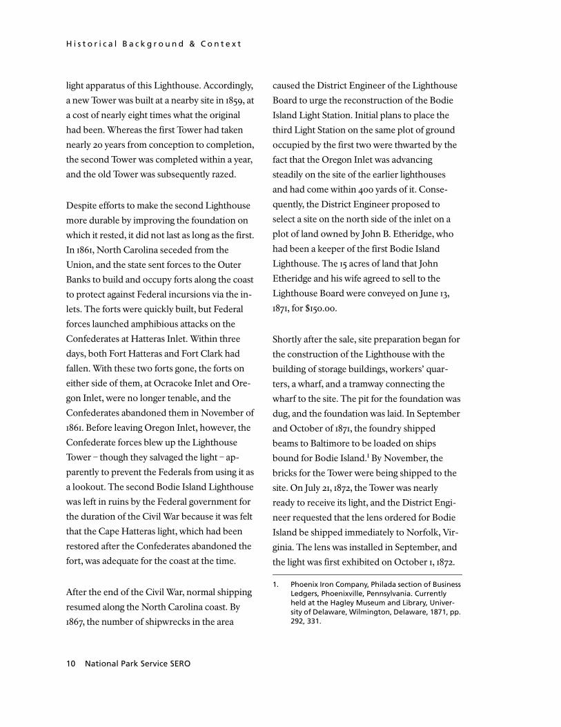
18 Drawing detail of north elevation. . . . . . . . . . . . . . . . . 59
19 Photo of south elevation by U.S. Coast Guard, 1948.. . . . . . . . . . . 60

viii National Park Service SERO
20 Drawing detail of Lighthouse base. . . . . . . . . . . . . . . . . . 64
21 Oil House, Hall (OH/100) . . . . . . . . . . . . . . . . . . . . 81
22 Plate XI, 1871 Drawings. . . . . . . . . . . . . . . . . . . . . 85
23 Well. . . . . . . . . . . . . . . . . . . . . . . . . . . . 87
24 Dedication Plaque. . . . . . . . . . . . . . . . . . . . . . . 87
25 Watch Room ceiling insert made of prismatic glass. . . . . . . . . . . . 89
26 Lens pedestal, original manufacturer’s brass plaque. . . . . . . . . . . . 89
27 First order Fresnel lens. . . . . . . . . . . . . . . . . . . . . . 90
28 South chimney above the Oil Room. . . . . . . . . . . . . . . . . 92
29 Three treads with notable cracks, below Landing #1. . . . . . . . . . . . 93
30 Detail of vertical crack on south side of masonry wall.. . . . . . . . . . . 94
31 Detail of masonry repair located above landing support beam.. . . . . . . . 95
32 Detail of water collecting on landing that accesses Service Room. . . . . . . . 95
33 Detail of peeling paint in Watch Room. . . . . . . . . . . . . . . . 96
34 View from Lantern Gallery. . . . . . . . . . . . . . . . . . . . 96
35 Detail of handrail. . . . . . . . . . . . . . . . . . . . . . . 99
36 Detail of utility meter. . . . . . . . . . . . . . . . . . . . . . 101
37 Detail of utility routing through door frame. . . . . . . . . . . . . . 101
38 Detail of electrical line. . . . . . . . . . . . . . . . . . . . . . 101
39 Detail of electrical wiring access to distribution panel. . . . . . . . . . . 101
40 Detail of distribution panel. . . . . . . . . . . . . . . . . . . . 101
41 Lightning rod installed on gallery handrail. . . . . . . . . . . . . . . 102
42 Conduit for lightning protection, located at tower base. . . . . . . . . . . 102
43 Detail of stair showing tread repair. . . . . . . . . . . . . . . . . 107
44 Detail of foundation showing mortar leaching. . . . . . . . . . . . . . 112

Bodie Island Lighthouse HSR ix
http://crs.sero.nps.gov/historic/hsr/malu
45 Detail of Fresnel lens. . . . . . . . . . . . . . . . . . . . . . 117
46 Floorplan with 16 axes. . . . . . . . . . . . . . . . . . . . . 133
47 Legend of assemblies.. . . . . . . . . . . . . . . . . . . . . 134

x National Park Service SERO

http://crs.sero.nps.gov/historic/hsr/malu
Bodie Island Lighthouse HSR xi
Project Team
Project Manager Danny Scheidt, Historical ArchitectNational Park ServiceSoutheast Regional OfficeAtlanta, GA
Contract Technical Representative Tommy Jones, Architectural HistorianNational Park ServiceSoutheast Regional OfficeAtlanta, GA
Building Reporters Deborah Harvey, Historical WriterHartrampf Inc.Atlanta, GA
Jack Pyburn, Historical Architect, AIAOJP, Inc.Atlanta, GA
Specialized Building Investigation Robert A. Bass, P.E., Structural EngineerAshraf Demian, P.E., Electrical EngineerHartrampf Inc.Atlanta, GA
Courtney Swann, Historical ArchitectOJP, Inc.Atlanta, GA
Document Layout/Internet Access
Jon Buono, Historical ArchitectJay Womack, HistorianNational Park ServiceSoutheast Regional OfficeAtlanta, GA
Program Reviews Bob Blythe, HistoryAllen Bohnert, Museum ServicesDanny Scheidt, Historic ArchitectureNational Park ServiceSoutheast Regional OfficeAtlanta, GA

xii National Park Service SERO

Bodie Island Lighthouse HSR xiii
Foreword
We are pleased to make available this historic structure report, part of our ongoing effort to pro-
vide comprehensive documentation for the historic structures and landscapes of National Park
Service units in the Southeast Region. Many individuals and institutions contributed to the suc-
cessful completion of this work. We would particularly like to thank the staff at Cape Hatteras Na-
tional Seashore for their assistance throughout the process. We hope that this study will prove
valuable to park management in their continuing preservation of the building and to everyone in
understanding and interpreting the Bodie Island Lighthouse and Oil House.
Dan ScheidtChief, Cultural Resources DivisionSoutheast Regional OfficeNational Park ServiceDecember 2004

xiv National Park Service SERO

http://crs.sero.nps.gov/historic/hsr/malu/e_sum
mary.htm
Bodie Island Lighthouse HSR 1
M A N A G E M E N T S U M M A R Y
Executive Summary
The area on which the Bodie Island Light Station now stands was
originally spelled Body’s Island. This spelling appears on many
early documents. It is not known how the island got its name or
when or why it was changed, though research is currently under-
way to determine the answer to those questions. The current
spelling, Bodie Island, is used throughout this document for the
sake of clarity unless directly referencing an original document
using the original spelling. The Bodie Island Lighthouse is signif-
icant in the understanding of the history of maritime navigational
aids used by the United States during the nineteenth and twenti-
eth centuries. It was constructed during a period of building of
several such aids along the shores of this country and stands
largely unchanged except for the means of powering the light.
The surroundings of the Bodie Island Lighthouse, unencum-
bered by visible signs of contemporary society, with the
exception of the access road, are also significant to the under-
standing of under what conditions the Lightkeepers lived and
worked in the last part of the nineteenth century and first half of
the twentieth.
In March of 2002, at the request of the National Park Service,
personnel from Hartrampf, Inc., engineers, and the Office of Jack
Pyburn, Architect, Inc. traveled to the Bodie Island Light Station

E x e c u t i v e S u m m a r y
2 National Park Service SERO
at Oregon Inlet near Nags Head, North Caro-
lina to undertake a physical inspection of the
Tower and attached Oil House, called, collec-
tively, the Bodie Island Lighthouse. The
purpose of the inspection was to provide in-
formation relative to the existing condition of
the structure involved in the course of compil-
ing this Historic Structure Report. Personnel
inspecting the site included Mr. Robert A.,
Bass, P.E., structural engineer, Mr. Ashraf
Demian, P.E., electrical engineer, and Ms.
Deborah Harvey, historical writer, of Har-
trampf, Inc. as well as Mr. Jack Pyburn, AIA,
Historic Architect and Mr. Courtney Swann,
Historic Architect, of the Office of Jack Py-
burn, Architect, Inc., with the assistance of Mr.
Steve Harrison, National Park Service Chief of
Resource Management at the Cape Hatteras
National Seashore, North Carolina.
Photographs, measurements, and notes were
taken regarding the subject structure, in addi-
tion to a video record of the investigation. In
accordance with the scope of work for this re-
port, no historic fabric was removed or altered
for this inspection, and no scaffolding or other
inspection structures were constructed. No
intrusive methods were used to inspect the
structures. Therefore, only observations of the
exterior surfaces of the Lighthouse normally
accessible were possible. On- site personnel
were interviewed about ongoing maintenance
and restoration efforts currently underway at
the site. A visit to the Cape Hatteras National
Seashore headquarters archives and offices in
Manteo, North Carolina was made by the rep-
resentatives of Hartrampf, Inc., and, with the
assistance of Mr. Steve Harrison, documents,
drawings, and photographs regarding the
Bodie Island Lighthouse were reviewed and
pertinent documents copied. A trip by Ms.
Deborah Harvey to the headquarters of the 5th
United States Coast Guard District in Ports-
mouth, Virginia and, later, to the Civil
Engineering Unit of the Shore Maintenance
Detachment of the United States Coast Guard
in Cleveland, Ohio, yielded further documen-
tation, including drawings, notes, sketches,
and reports, regarding the use and mainte-
nance activities of the Government at the
Bodie Island Light Station from its construc-
tion in 1872 to the present. Documents
provided by the National Park Service, includ-
ing a copy of A History of the Bodie Island Light
Station, prepared in 1967 by Francis R. Hol-
land, Jr. and published by the National Park
Service, several recent structural evaluations of
the Tower and Oil House, and an historic paint
survey, completed by John H. Scott of the Na-
tional Park Service in 2002, were also reviewed.
An interested researcher, Jack McCombs, pro-
vided information regarding the steel
fabricating company, and the book, Lighthouse
Families, by Cheryl Shelton- Roberts, gave in-
sight into the lives of Lightkeepers and their
families. Ms. Harvey also conducted corre-
spondence with Jack McCombs, Cheryl
Shelton- Roberts, and John Gaskill, son of the
last Lightkeeper, which produced further per-
tinent information about the history of the
Lighthouse.
The Bodie Island Lighthouse is within the en-
virons of the Cape Hatteras National Seashore.

M A N A G E M E N T S U M M A R Y
http://crs.sero.nps.gov/historic/hsr/malu/e_sum
mary.htm
Bodie Island Lighthouse HSR 3
There is a General Management Plan extant
for the Cape Hatteras National Seashore.
However, it was formulated prior to the acqui-
sition of the Bodie Island Lighthouse in 2000
and, thus, contains no directives regarding use
or preservation requirements for this struc-
ture. There is no Period of Significance
established in the General Management Plan
for the Bodie Island Lighthouse. In the absence
of such direction, this report proposes that the
Bodie Island Lighthouse be preserved to inter-
pret its ongoing use as a maritime navigational
aid.
Since changes to the building have been mini-
mal, all eras of the history of the building can
be interpreted, requiring only minor alter-
ations to its present condition to allow for safe
visitor access to the building. The United
States Coast Guard expects to continue opera-
tion of the light for another eight or ten years.
When that use ceases, the National Park Ser-
vice may want to re- evaluate the significance
of the Bodie Island Light Station within the
context of an overall interpretive plan for all
the surviving lighthouses on the Outer Banks.
While there is no compelling rationale for re-
storing it to an earlier period at the present
time, the National Park Service may decide
later that the Bodie Island Light Station has
special significance and that to properly inter-
pret that significance, restoration to some
earlier period is required.
Findings of the physical investigation and re-
view of historic documents indicate that the
Bodie Island Lighthouse, while essentially
sound, has been the victim of 131 years of wind,
weather, and insensitive maintenance activity.
This is not to say that the Lighthouse Board
and the United States Coast Guard did not en-
gage in maintenance activities during their
tenures as keepers of the structure. The main
focus of both government entities was to
maintain the light as a navigational aid, and
their efforts did not focus on the preservation
of the historic features of the building or on
relating improvements to the structure’s his-
tory or historical context. Consequently, when
replacing surface finishes, repairing damage, or
re- installing weathered features, the focus was
not on keeping the historic fabric intact, but on
keeping the facility functioning as a lighthouse.
A major concern regarding this building is
whether or not it is structurally sound and can
be opened for visitation by the public. In gen-
eral, the structure is sound and could be
opened, with some restrictions, for visitation
by the public after modifications suggested
herein have been made. The foundations and
loadbearing walls, while experiencing some
deterioration of mortar that might be expected
in a 131- year old structure in a coastal setting,
are stable and require only minor repairs. De-
terioration of metal parts has occurred and
must be remedied. The structural evaluation
indicates that the stair treads and landings can
support the loads mandated by current build-
ing codes; however, the stair stringers would
require bracing before any wholesale visitation
by the public could occur. The conclusion re-
garding the gallery on the outside of the Tower
is that it should be repaired as necessary for
maintenance of the exterior and to replace lost

E x e c u t i v e S u m m a r y
4 National Park Service SERO
features. To open the gallery to the public, it
will be necessary to strengthen the support
structure and replace the handrail with one
that complies with current codes.
Visitor management will be an issue at the
Bodie Island Lighthouse. Fall protection at
landing and stair handrails and at window
openings must be provided. The physical size
of the upper landings, especially the Watch
Room and Lantern level, will restrict the num-
ber of people that can be accommodated to
possibly no more than four or five on these
levels at any one time. Therefore, a manage-
ment strategy must be devised to coordinate
public access with the capacity of the stairs and
landings. To allow access to the top level, the
Lantern level, a handrail must be installed
along the stairs leading from the Watch Room
to the Lantern level. These stairs are excep-
tionally steep and narrow, with no handholds
of any kind. However, it seems imperative that,
if the National Park Service allows visitors to
the top of the Tower, they must be allowed to
the Lantern level, as there is no other means of
physically viewing and appreciating the light,
the lens, the lamp, and the landscape.
Access for the physically disabled is an issue at
the Bodie Island Lighthouse. The Lighthouse
has never been an accessible structure. The
building type, in general, is one designed for a
unique use, and the configuration of the struc-
ture reflects that use. Applying the standards
for physical modification to achieve accessi-
bility in accordance with the Americans with
Disability Act, UUDAG, and UFAS is not pos-
sible without producing a significant negative
effect on the historic character of the structure.
Therefore, the application of “minimum alter-
native access” as provided for in the
consultation procedures of ADAAG 4.1.7(2)
(56 Federal Register 35429, July 26, 1991)
should be applied to this structure. The type of
responses appropriate under the “minimum
alternative access” provisions could include
such elements as accessible observation points
on the ground to view building features, videos
interpreting the experience of ascending the
tower and viewing from the watch balcony, or
scale cutaway models of the interior of the
structure for viewing at the Visitor Center.
The following represents a summary of the
treatment recommended to preserve the Bodie
Island Lighthouse and provide a safe and en-
joyable visitor experience.
Paint Removal
• Perform lead paint abatement on all
painted surfaces of the exterior and inte-
rior of the Oil House and Tower where
necessary. Where lead paint is not indi-
cated, remove paint to expose surfaces for
inspection.
Masonry
• Inspect the granite, brick, and mortar
forming the foundation and walls of the Oil
House, Hall Connection, and Tower and
document conditions.
• Repair cracks in foundations and walls
using an appropriate method.

M A N A G E M E N T S U M M A R Y
http://crs.sero.nps.gov/historic/hsr/malu/e_sum
mary.htm
Bodie Island Lighthouse HSR 5
• Perform tests on the mortar to determine
its composition and repoint the founda-
tions and walls using appropriate methods
and mortars.
Metal
• Inspect metal surfaces and features, docu-
ment conditions, and repair or replace in
kind as necessary.
• Install structural strengthening members as
necessary to bring the gallery up to code to
allow visitor access.
Wood
• Repair or replace in kind as necessary
damaged existing wood features in the Oil
House and Hall Connection.
Glass
• Reglaze the exterior panes of the lamp,
replacing clouded or crazed panes.
• Reglaze windows as necessary in Oil
House and Tower.
Roofing
• Remove existing Oil House roof, inspect
the roof framing over the Oil House and
Hall Connection, and document condi-
tions.
• Replace any rotted members discovered
during the inspection of the roof framing.
• Inspect the east chimney to verify that the
chimney is not experiencing distress below
the roof line.
• Install a new roof deck, new roof flashings,
and new roofing on the Oil House and Hall
Connection.
• Inspect the roof of the Tower and the ven-
tilator ball at the top for damage, document
conditions, and repair or replace if inspec-
tion indicates that this is necessary.
Flooring
• Refinish and seal the wood floor in the
Work Room.
• Clean the marble floors in the Oil House
and Tower and replace any cracked or
missing tiles.
• Securely install replacement prisms in the
Lantern level grating floor.
Safety
• Install a new, code- compliant railing
around the existing exterior gallery.
• Modify the stair and landing level railings
to provide fall protection.
• Install bracing on each side of stairs, mid-
flight, to bring the stair stringers up to
code.
• Install fall protection at the openings to the
windows on the 2nd, 5th, and 8th level land-
ings.
• Fabricate and install a railing conforming to
current code requirements at the stair from
the Watch Room level to the Lamp level.
• Remove the chain link enclosure at the
base of the Tower stairs and repair the walls
and floor of the ground level of the Tower
as necessary.

E x e c u t i v e S u m m a r y
6 National Park Service SERO
• After reconstruction of the exterior metal
gallery, remove the exterior wood fence
around the Tower.
Electrical
• Verify the presence of asbestos insulation
in wiring prior to making any repairs.
• Repair and replace electrical wiring and
fixtures as necessary.
• Add lightning protection at the highest
point of the Tower with two down con-
ductors. Verify the connection of the exist-
ing lightning protection ground
conductors. If the connection cannot be
verified, install a new ground ring with
ground rods.
Painting
• After repair, replacement, and modifica-
tion of Lighthouse features have been
completed, paint the Oil House and Tower
using an historically- appropriate paint
scheme.
Maintenance
• Implement a systematic program to open
the windows regularly to provide ventila-
tion and reduce moisture condensation on
the interior of the Tower.
• Implement a systematic program to inspect
the underside of the stair treads for future
stress cracks.
The conclusion is that the Bodie Island Light-
house is essentially in sound structural
condition. Original physical features are sub-
stantially intact. Additionally, it is feasible to
open it to the public, with some limitations.
With coordinated, historically- appropriate
physical improvements and a creative inter-
pretive plan, the Lighthouse can be managed to
achieve a safe and satisfying visitor experience
while protecting the significant historic quali-
ties and features of the structure and
maintaining it as an active maritime aid to
navigation.

M A N A G E M E N T S U M M A R Y
http://crs.sero.nps.gov/historic/hsr/malu/e_sum
mary.htm
Bodie Island Lighthouse HSR 7
Administrative Data
Location Data
Building Name: Bodie Island Lighthouse
Building Address: Bodie Island Lighthouse, Nags Head,North Carolina
LCS # 00114
Related Studies
Holland, Francis R., Jr. A History of the Bodie Island Light Station, National Park Service History Department, 1967.
National Park Service, Historic Paint Finishes Study, Bodie Island Lighthouse and Oil House, National Park Service Northeast Cultural Resources Center Building Conservation Branch, 2002.
Cultural Resource Data
National Register of Historic Places: The Bodie Island Light
Station is eligible for listing in the National Register of Historic
Places. A register nomination is being prepared by the National
Park Service for this structure.

A d m i n i s t r a t i v e D a t a
8 National Park Service SERO
Period of Significance: The Period of Signifi-
cance for the Bodie Island Lighthouse begins
in 1872, when construction was completed and
the light was first displayed as a navigational
aid. The end of the Period of Significance has
not yet been determined. Several options are
available: 1872, the original condition; 1932, af-
ter the conversion of the Light Station from oil
to electricity; 1940, the year the last Light-
keeper left Bodie Island; 1945, the year the
Bodie Island Light Station site reached its
present size; 1953, when the Light Station was
converted to commercial electricity; or 2000,
when the Lighthouse was transferred from the
United States Coast Guard to the National
Park Service. Each of these periods (1872 – 1932,
for example) present unique characteristics,
though they are, except for the last, mainly re-
lated to the production of light in the Tower.
The adoption of most of these would probably
necessitate the removal of some later features
and the re- installation of missing components
known to have existed and for which there is
documentary evidence regarding the appear-
ance of the missing feature. In the absence of
direction in the General Management Plan of
the Cape Hatteras National Seashore for the
Bodie Island Lighthouse, the authors of this
report, with the concurrence of the National
Park Service, recommend that the Period of
Significance be defined as the period in which
the Lighthouse was used as an active naviga-
tional aid. Thus, the Period of Significance
represents the collective history of the struc-
ture, a history that is not yet completed since
the Lighthouse is still in use as an aid to navi-
gation. At such time as the Bodie Island
Lighthouse ceases to be used as an aid to navi-
gation, the National Park Service may decide
to modify this approach and determine a less
inclusive Period of Significance. If so, the Park
Service should open dialogues with represen-
tatives of families and groups in surrounding
communities with historic ties to the Light-
house, such as those who had ancestors who
worked at the Lighthouse, who would qualify
as “traditionally associated peoples,” as de-
fined in National Park Service management
policies for ethnographic resources.
Proposed Treatment and Use: The Light Sta-
tion remains in use as an aid to navigation, but
it is also an attraction to visitors to the area.
The treatment is to preserve the Tower and the
Oil House, known collectively as the Light-
house as it has evolved into the 21st century.
While some modifications are necessary to ad-
dress safety issues, the Lighthouse would
essentially be only repaired to preserve the ex-
isting structure with no modifications made to
the structure except to accommodate limited
visitor access. Restoration of features removed
in the course of the use of the Lighthouse as a
navigational aid are not recommended. How-
ever, recent modifications that are not related
to the use of the Lighthouse as an aid to navi-
gation, such as the fences installed to prevent
injury to visitors, could be removed. The Gen-
eral Management Plan for the Cape Hatteras
National Seashore should be revised to include
a plan for this structure that addresses contin-
ued maintenance and visitor access.

http://crs.sero.nps.gov/historic/hsr/malu/e_sum
mary.htm
Bodie Island Lighthouse HSR 9
P A R T 1 D E V E L O P M E N T A L H I S T O R Y
Historical Background & Context
The historical background of the Bodie Island Lighthouse has
been ably documented by Francis R. Holland, Jr. in his report,
History of the Bodie Island Light Station, written in 1967 and
printed by the U.S. Department of the Interior, National Park Ser-
vice. A copy of his report is included as an appendix to this report.
Therefore, this section does not undertake to repeat Holland’s
work, but includes a summary based on that work, with some ad-
ditional information not included in Holland’s. Footnoting will
not be provided for information in this section that is derived
from Holland’s History, but only for information from other
sources that applies to the period from 1848 to 1954. The history of
the Bodie Island Lighthouse is resumed in this report beginning at
1954, the last year documented in Holland’s book.
The existing Lighthouse at Bodie Island is the third built in this vi-
cinity, but it is not on the foundations of either of the first two.
The foundations of the first two Bodie Island Lighthouses are now
under water in the Oregon Inlet. The first Lighthouse was com-
pleted in 1848, but, only ten years later, it was necessary to replace
it due to defects in the foundation. The foundation had not been
designed to accommodate the soils on which the structure was
placed, causing it to settle unevenly, leaning nearly a foot out of
plumb by 1851. In addition, the decision was made to upgrade the
H i s t o r i c a l B a c k g r o u n d & C o n t e x t
10 National Park Service SERO
light apparatus of this Lighthouse. Accordingly,
a new Tower was built at a nearby site in 1859, at
a cost of nearly eight times what the original
had been. Whereas the first Tower had taken
nearly 20 years from conception to completion,
the second Tower was completed within a year,
and the old Tower was subsequently razed.
Despite efforts to make the second Lighthouse
more durable by improving the foundation on
which it rested, it did not last as long as the first.
In 1861, North Carolina seceded from the
Union, and the state sent forces to the Outer
Banks to build and occupy forts along the coast
to protect against Federal incursions via the in-
lets. The forts were quickly built, but Federal
forces launched amphibious attacks on the
Confederates at Hatteras Inlet. Within three
days, both Fort Hatteras and Fort Clark had
fallen. With these two forts gone, the forts on
either side of them, at Ocracoke Inlet and Ore-
gon Inlet, were no longer tenable, and the
Confederates abandoned them in November of
1861. Before leaving Oregon Inlet, however, the
Confederate forces blew up the Lighthouse
Tower – though they salvaged the light – ap-
parently to prevent the Federals from using it as
a lookout. The second Bodie Island Lighthouse
was left in ruins by the Federal government for
the duration of the Civil War because it was felt
that the Cape Hatteras light, which had been
restored after the Confederates abandoned the
fort, was adequate for the coast at the time.
After the end of the Civil War, normal shipping
resumed along the North Carolina coast. By
1867, the number of shipwrecks in the area
caused the District Engineer of the Lighthouse
Board to urge the reconstruction of the Bodie
Island Light Station. Initial plans to place the
third Light Station on the same plot of ground
occupied by the first two were thwarted by the
fact that the Oregon Inlet was advancing
steadily on the site of the earlier lighthouses
and had come within 400 yards of it. Conse-
quently, the District Engineer proposed to
select a site on the north side of the inlet on a
plot of land owned by John B. Etheridge, who
had been a keeper of the first Bodie Island
Lighthouse. The 15 acres of land that John
Etheridge and his wife agreed to sell to the
Lighthouse Board were conveyed on June 13,
1871, for $150.00.
Shortly after the sale, site preparation began for
the construction of the Lighthouse with the
building of storage buildings, workers’ quar-
ters, a wharf, and a tramway connecting the
wharf to the site. The pit for the foundation was
dug, and the foundation was laid. In September
and October of 1871, the foundry shipped
beams to Baltimore to be loaded on ships
bound for Bodie Island.1 By November, the
bricks for the Tower were being shipped to the
site. On July 21, 1872, the Tower was nearly
ready to receive its light, and the District Engi-
neer requested that the lens ordered for Bodie
Island be shipped immediately to Norfolk, Vir-
ginia. The lens was installed in September, and
the light was first exhibited on October 1, 1872.
1. Phoenix Iron Company, Philada section of Business Ledgers, Phoenixville, Pennsylvania. Currently held at the Hagley Museum and Library, Univer-sity of Delaware, Wilmington, Delaware, 1871, pp. 292, 331.

P A R T I D E V E L O P M E N T A L H I S T O R Y
http://crs.sero.nps.gov/historic/hsr/malu/e_sum
mary.htm
Bodie Island Lighthouse HSR 11
Figure 1 Bodie Island Light, 1893.
The total cost for the Light Station was
$140,000.00.
The arrangement for maintenance of the Light
Station involved, in 1872, the employment of a
Principal Keeper, a 1st Assistant Keeper, a 2nd
Assistant Keeper, and, for the first two years, a
3rd Assistant Keeper. Between 1872 and 1940,
four Principal Keepers served the Bodie Island
Light Station.2 The first Principal Keeper at
Bodie Island Light Station was William F. Hat-
sel, of North Carolina, who was employed until
1878 at a salary of $820 per year. Peter Johnston
was assigned as the 1st Assistant Keeper on Oc-
tober 15, 1872 at a salary of $400 per year, and
W. E. Etheridge was the 2nd Assistant Keeper,
assigned October 11, 1872 at a salary of $350 per
year. By 1874, the office of 3rd Assistant Keeper,
held by Rebecca Hatsel, wife of the Keeper, had
been abolished. Over the next five years, a suc-
cession of 1st and 2nd Assistant Keepers rotated
in and out of the service of the Bodie Island
Light Station.
Keeper William F. Hatsel was transferred from
Bodie Island in July of 1878 and replaced by Pe-
ter G. Gallop of Maryland, who seems to have
remained in that position until 1906. The fre-
quent reassignment of Assistant Keepers
continued. In 1887, the first pay raise for Assis-
tant Keepers was approved: John Shannon, 2nd
Assistant Keeper, was given a raise from $425 to
$450 per year, putting his salary on par with
that of the 1st Assistant Keeper. A year later,
George Blivens, 1st Assistant Keeper, received a
raise of $50 per year, his salary rising from $450
to a whopping $500 per year!
In 1906, Keeper Peter G. Gallop was replaced
by Ephraim Meekins, Jr. Meekins accepted the
position with a decrease in the base pay for
Keepers from $820 per year to $720 per year.
The Assistant Keepers’ pay rates apparently re-
mained the same. By 1911, the 2nd Assistant
Keeper was making $456 per year. Still, Assis-
tant Keepers were mostly transient; several
were appointed nearly every year. In late 1919,
Keeper Meekins relinquished his position to
the fourth and final Principal Keeper at Bodie
Island, Lloyd Vernon Gaskill.3 In the 1920s, the
position of 2nd Assistant Keeper was abolished 2. McComb, Jack, to Deborah E. Harvey, e-mail dated
23 April 2002.

H i s t o r i c a l B a c k g r o u n d & C o n t e x t
12 National Park Service SERO
thanks to the installation of a “mechanical
keeper,” a thermostat positioned over the ker-
osene lamp flame and attached to a warning
bell located in the Keepers’ Quarters and to a
recording device to notify the Keeper if the
light went out and to record the event.4
The apparently high turnover may have been
the result of long hours and an isolated condi-
tion for the Lightkeepers. A report in 1909
indicates that the only means of reaching the
Light Station was by a small sailboat to a land-
ing and then on foot down a sandy road almost
½- mile long.5 Later, the Lighthouse had a
powerboat that transported people and sup-
plies to the island.6 This situation was not
rectified until the late 1920s, when a bridge to
the island was built.7 In 1909, the distance to the
nearest post office was six miles, and to the
nearest steamboat landing and town, 12 miles.8
Because there were no schools or churches on
Bodie Island, Keeper Gaskill, as well as his as-
sistant keepers, housed his family on Roanoke
Island at Wanchese for the majority of the year,
moving them to Bodie Island only in the
summer.9
The duties of the Keepers were incessant.
When there were three keepers, two of the
three men were on duty at all times.10 Until the
“mechanical keeper,” the thermostat, was in-
stalled, a Keeper had to be in the Watch Room
whenever the lamp was lit.11 A small coal stove
helped to dispel the cold for the Keeper on
duty.12 Keeper Gaskill kept the first watch, and
one of his assistants relieved him about mid-
night.13 After the installation of the thermostat
and the elimination of one of the Assistant
Keeper positions, the two remaining Keepers
alternated nights on watch.14 John Gaskill de-
scribed his father’s routine for Cheryl Shelton-
Roberts in Lighthouse Families:
“Daddy would come out here about thirty min-
utes before sundown. He would go to the storage
house that was outside the tower on the south
side, fill a three- gallon brass can with oil, and get
a bucket of coal. Next he would climb the stairs
to the watch room, fill the oil reservoir, and
watching the gauges carefully, pump the oil to
pressurize it and send it upward into the mantle
in the center of the Fresnel lens in the lantern
room. Then Daddy would climb the stairs to the
lantern room, go in, take the alcohol torch from
its holder, light the torch, and use it to warm the
3. Gaskill, John, to Deborah E. Harvey, e-mail dated 22 April 2002.
4. Shelton-Roberts, Cheryl, and Bruce Roberts, Light-house Families, Cranehill Publishers, Birmingham, 1997, p. 159.
5. ----, “Description of Lighthouse Tower, Buildings, and Premises”. Report for the U.S. Department of
Commerce and Labor, in papers of the 5th United States Coast Guard District headquarters, Ports-mouth, Virginia, dated 6 Mar 1909, pp. 3-4.
6. Shelton-Roberts, p. 163.7. Gaskill, John, to Deborah E. Harvey, e-mail dated
26 April 2002.8. ----, “Description of Lighthouse Tower, Buildings,
and Premises,” pp. 3-4.9. Gaskill, John, to Deborah E. Harvey dated 26 April
2002.
10. Shelton-Roberts, pp. 158-159.11. Ibid, p. 171.12. Ibid.13. Ibid.14. Gaskill, Lloyd Vernon, “Personnel Classification
Board Form No. 14 – Field Questionnaire” com-pleted for the Lighthouse Board, certified as accurate and complete 21 Sept 1928 by H. D. King, Superintendent of Lighthouses, from Lloyd V. Gaskill papers at Cape Hatteras National Seashore headquarters, Manteo, North Carolina. Original documents in the possession of John Gaskill, his son.

P A R T I D E V E L O P M E N T A L H I S T O R Y
http://crs.sero.nps.gov/historic/hsr/malu/e_sum
mary.htm
Bodie Island Lighthouse HSR 13
kerosene to vaporize it. The kerosene vapor
burned in the mantle, producing a brilliant
light.”15
However, keeping the light lit was not the only
task assigned to the Keepers. In 1928, Lloyd
Vernon Gaskill described his work:
“(1) As keeper in charge of this station, I am
responsible for the for the [sic] proper execution
of the duties whether performed by my self [sic]
or Asst. I light lamp in tower every othe [sic]
evening and raise curtains so the light will be vis-
ible to passing ships. Asst. Keeper performs the
same duty the following evening. I watch the
light intervals untill [sic] sunrise when I extin-
guish light and refill tanks with kerosene so it will
be ready for lighting in the evening. Also I clean
lens and watch room before coming [sic] down
to dwelling. I am on duty about twelve hours in
this instance. (2) I have one Asst. and I superin-
tend and assist in painting, cleaning paint on
outhouses and dwelling, clean iron work by
chipping ruse [sic] from same when needed. Also
keep grass cut on lawn, make minor repairs to
sta. such as replaceing [sic] lantern glass when
broken, repairing doors, replaceing [sic] hinges
when broken, painting motor boat and skiff,
keep engine repaired so it can be used at any time
for getting supplies and mail from nearest store
and Post Office seven miles across the sound. I
put in about five hours per day at this work. (3)
In addition to above duties I must make a weekly
inspection of Sta. Including assistants quarters
and record made of condition of Sta. log. Make
monthly report of condition of Sta. to district
Supt. at Baltimore. Take annual inventory and list
all articles worn out have them surveyed and
condemed [sic] when Supt. visits sta. on inspec-
tion. Also I superintend and assist in the painting
of tower outside, steps inside, and whitewash
once every five years. I attend to all correspon-
dence from sta. with Supt. relative to general
repairs to station. I average about two hours per
day at this work.”16
In addition to the long hours, the quarters were
somewhat cramped, making it difficult for
Keepers and their Assistants to have their fami-
lies with them. One building at the Bodie Island
Light Station, designed as a duplex known as a
Double Keepers Quarters (DKQ), was ex-
pected to serve both the Keeper and his family
and any Assistant Keepers assigned to the sta-
tion. By the end of the 1800s, the Lighthouse
Board had decided that a second Keeper’s
Quarters at Bodie Island would be desirable. It
was determined that the Assistant Keepers
could share the existing Double Keepers Quar-
ters and that a new, larger residence should be
built for the Principal Keeper. Several plans for
these changes were drawn.17 However, they
were unable to convince Congress to appropri-
ate the approximately $7,500 it would cost for
construction of the second dwelling and asso-
ciated cistern and outhouse until 1907. By that
time, the cost of the second dwelling had risen,
and the Lighthouse Board was unable to design
a structure that would be within the limits of
15. Shelton-Roberts, p. 171.
16. Gaskill, “Personnel Classification Board Form No. 14 – Field Questionnaire,” n.p.
17. Assorted plat plans and building designs in papers of the Civil Engineering Unit, Shore Maintenance Detachment, United States Coast Guard, Cleve-land, Ohio, various dates.

H i s t o r i c a l B a c k g r o u n d & C o n t e x t
14 National Park Service SERO
the authorized amount. The matter was
dropped.
In 1910, the Lighthouse Board was abolished
and the Bureau of Lighthouses created. The
Bureau apparently consisted of one person, the
Commissioner of Lighthouses. The lighthouse
service was transferred from the Treasury De-
partment to the Department of Commerce.
Between 1919 and 1937, the families of Keeper
Gaskill and his Assistant Keeper lived in
Wanchese on Roanoke Island during the win-
ter months so that their children could attend
school regularly.18 However, by 1937, Gaskill
had reached an agreement with the local school
board to transport the children daily to and
from the main highway, where they could
board a school bus. The school board agreed to
furnish the gasoline used to transport the chil-
dren to the highway. For this reason, Gaskill’s
wife, Bertha, and youngest daughter, Erline,
were able to live on Bodie Island year- round,
the older children having already left home.19
Gaskill enquired of the Commissioner of
Lighthouses regarding reimbursement for car
repairs and tires incidental to the transporta-
tion of the children, but was rejected. However,
the following year, the school board agreed to
pay for only 75 percent of the cost of gasoline
(60 of the 80 gallons used). Gaskill asked the
Commissioner of Lighthouses to provide the
remainder, only 14 gallons since the owner of
the Bodie Island Hunt Club, near the Light Sta-
tion, was paying for six gallons so that his
children could ride to the school bus with the
children of the Keeper. The Commissioner ac-
ceded to his request on the condition that he
provide information on the cost of gasoline and
whether it would be taken from official stock or
purchased privately. According to Holland, be-
cause the cost of a gallon of gasoline was, at that
time, about seven and three- quarters cents, the
expenditure of $1.08 by the Commissioner of
Lighthouses required about $20 in paperwork.
In 1937, the Cape Hatteras National Seashore
was authorized, and, in 1938, the Department of
the Interior expressed an interest in the Bodie
Island Light Station, which was rumored to be
on the verge of being declared surplus. This,
and the reorganization of the Bureau of Light-
houses in 1939, when the Bureau was
consolidated with the United States Coast
Guard, caused some consternation among the
Lighthouse Keepers and prompted letters of
inquiry from Gaskill to the Commissioner of
Lighthouses as well as to his State Representa-
tive, Lindsay Warren, regarding his status.20 He
was assured by both the Commissioner of
Lighthouses and President of the local Federal
Employees Union that neither his position nor
his salary was in jeopardy. He also received a
soothing letter from Representative Warren,
who informed him that an increase at Bodie Is-
land was being considered. Additionally, his
salary was raised to $1,740 per year.21 However,
the transfer of the lighthouses to the care of the
Coast Guard did have an impact on Lloyd Ver-
18. Gaskill, John, to Deborah E. Harvey, 24 April 2002.19. Shelton-Roberts, pp. 166-167, 170.
20. Lloyd V. Gaskill papers.21. Short, Oliver C., Director of Personnel, Depart-
ment of Commerce, in letter to Lloyd V. Gaskill, dated 16 Jun 1930, in Lloyd V. Gaskill papers.

P A R T I D E V E L O P M E N T A L H I S T O R Y
http://crs.sero.nps.gov/historic/hsr/malu/e_sum
mary.htm
Bodie Island Lighthouse HSR 15
non Gaskill’s life. In May of 1940, he was
transferred from Bodie Island to Coinjock to
replace a retiring Keeper, and was then as-
signed to a buoy tender depot, a position of
enormous responsibility.22 The letter inform-
ing him of the transfer stated, “This detail is
temporary, but it is anticipated you will not re-
turn to Bodie Island, and that your present
temporary detail will become permanent.”23 At
the same time, the Commander of the Norfolk
District (5th District) of the Coast Guard, sent a
letter to the Officer- in- Charge at the Nags
Head Coast Guard Station stating that, as a re-
sult of the transfer of Lloyd V. Gaskill to the
Coinjock Light Station and the transfer of As-
sistant Keeper, J. H. Austin, to the Sharps Island
Light Station, the Bodie Island Light Station
would be unmanned, making it necessary for
the Officer- in- Charge to undertake the opera-
tion of the Light Station.24 Lloyd V. Gaskill’s
records show that the Bodie Island Light Sta-
tion became an unmanned station at 6:30 a.m.
on May 22, 1940.25
In 1945, the size of the Bodie Island Light Sta-
tion site increased by slightly over 40 acres.
However, in 1953, the property was declared
surplus, and the General Services Administra-
tion at last listed the 56.37 acres of the Bodie
Island Light Station for disposal. The National
Figure 2 1964 NPS photograph showing sign to nature trail.
Park Service requested that the land be added
to the Cape Hatteras National Seashore. This
was established by Secretarial Order on January
12, 1953. On October 15, 1953, the Coast Guard
relinquished all of the land of the Bodie Island
Light Station except a small, square plot of
ground, 100 feet on each side, on which the
Lighthouse stands, to the National Park Ser-
vice. The Coast Guard continued to operate the
Lighthouse, though automation eliminated the
need for a resident Keeper of the light.
The National Park Service and the Coast Guard
cooperated on the maintenance and operation
of the Bodie Island Light Station property. The
Coast Guard signed agreements with the Na-
tional Park Service to allow a nature trail and an
observation deck to be built on the Lighthouse
grounds. A parking lot to the northwest of the
Double Keeper’s Quarters was also con-
structed. Photographs from 1964 and 1969
22. Shelton-Roberts, p. 167.23. Crapster, T. G., in letter to L.V. Gaskill, Keeper,
Bodie Island Light Station, dated 20 May 1940, from Lloyd V. Gaskill papers.
24. Crapster, T. G., in letter to Officer-In-Charge, Nags Head Coast Guard Station, Manteo, North Caro-lina, dated 20 May 1940, from Lloyd V. Gaskill papers.
25. Gaskill, Lloyd V., trip report dated 22 May 1940 in Lloyd V. Gaskill papers,

H i s t o r i c a l B a c k g r o u n d & C o n t e x t
16 National Park Service SERO
show the location of the parking as well as the
observation deck located to the south of the
Lighthouse.26 In 1972, permission was granted
to Offshore Navigation, Inc. to temporarily in-
stall a 3- pound radar beacon on the Lighthouse
in connection with their seismographic opera-
tion, provided this installation did not conflict
with the environmental program involving the
osprey in which the Coast Guard was partici-
pating.27 Also in 1972, the Coast Guard and the
National Park Service discussed an agreement
to allow public access to portions of the Light-
house, provided that it did not interfere with
the operation of the light. The Coast Guard
asked the National Park Service to agree to as-
sume responsibility for maintaining those
portions of the Lighthouse that were open to
the public, which included all portions of the
structures except the Generator Room (Oil
Room) in the Oil House and the Lamp in the
Tower. In addition, the National Park Service
was to agree not to allow nighttime visitors to
the Lighthouse without the installation of a
Coast Guard- approved lighting system, to re-
imburse the Coast Guard for any damages to
the Lighthouse caused by the National Park
Service or its visitors, to make some required
safety improvements to the Lighthouse, and to
hold the Coast Guard harmless from liability
for injuries sustained by Park Service staff or
visitors to the Lighthouse, in addition to main-
taining the grounds around the structures. The
agreement was signed in June of 1973.28 How-
ever, the National Park Service apparently still
did not have access to the interior of the Oil
House and the Tower in 1976, when the Coast
Guard was reported to be making some im-
provements on the Oil House.29
In November of 1977, the Heritage Conserva-
tion and Recreation Service submitted a
nomination for the Bodie Island Light Station
to be added to the National Register of Historic
Places. The Coast Guard was concerned that
this was done without their concurrence.30
Their concern was that a National Register list-
ing would impede any maintenance activities
they might want to undertake at the Light-
house. However, the nomination was never
forwarded to the National Register, and the
matter lapsed.
The Coast Guard allowed the firm of Brown
and Caldwell, consulting engineers to install a
26. Photographs from Bodie Island Lighthouse papers at Cape Hatteras National Seashore headquarters, Manteo, North Carolina.
27. Bullard, Ross P., Rear Admiral, U. S. Coast Guard,
Commander, 5th Coast Guard District in letters to
Offshore Navigation, Inc. from papers of the 5th United States Coast Guard District headquarters, Portsmouth, Virginia, dated 5 May 1972 and 11 May 1972.
28. “Use Agreement, Bodie Island Light,” signed by T. N. Miller, Property Officer for the U. S. Coast
Guard, 5th Coast Guard District, and Robert D. Bar-bee, Superintendent, of Cape Hatteras National Seashore, National Park Service, Department of
the Interior, from papers at the 5th United States Coast Guard District headquarters, Portsmouth, Virginia, dated June 19/23, 1973.
29. Garner, John C., Jr., Historic Architect, Planning and Compliance Division, Southeast Region, National Park Service “Memorandum” to the Regional Director, Southeast Region, National Park Service, in the papers at the Cape Hatteras National Seashore headquarters at Manteo, North Carolina, dated 4 November, 1976.
30. ----, Commandant, United States Coast Guard, in
letter to the Commander of the 5th United States
Coast Guard District, from papers of the 5th United States Coast Guard District headquarters, Portsmouth, Virginia, dated August, 1978.

P A R T I D E V E L O P M E N T A L H I S T O R Y
http://crs.sero.nps.gov/historic/hsr/malu/e_sum
mary.htm
Bodie Island Lighthouse HSR 17
temporary transponder on the gallery of the
light tower during the month of July 1981.31 This
was part of an oceanographic study being con-
ducted by the firm for the preliminary design
and siting of a wastewater ocean outfall off-
shore of Kill Devil Hills, North Carolina.32 The
transponder was mounted on a surveyor’s tri-
pod, so no intrusion into the fabric of the
lighthouse was necessary.
In May of 1983, the National Park Service ob-
tained permission from the Coast Guard to
present historical programs inside the Oil
House and the lowest level of the Tower.33 The
National Park Service proposed to provide a
movable barrier to block access to the upper
portions of the Tower and to perform routine
interior maintenance.34 National Park Service
personnel would be stationed within the Light-
house four hours a day, five days a week, to
answer questions, The Coast Guard indicated
that they would install a door to the Generator
Room (Oil Room), which was to be off limits to
the public.35 By November, the Coast Guard
had decided to install a more permanent barrier
to block public access to the Tower than that
provided by the National Park Service. An 8’
high chain link fence with a locking access door
was installed at the foot of the spiral stairs to
the Tower.36 Visitors were then allowed to en-
ter the lowest level of the Lighthouse and peer
up the shaft toward the Watch Room level.
However, on August 7, 1988, the National Park
Service and the United States Coast Guard
jointly commemorated the bicentennial of the
Lighthouse Service by escorting visitors to the
top of the Tower. One Coast Guard escort
climbed the first half of the Tower stairs with
the visitors, and another escorted them the rest
of the way.37 A year later, Captain BMC Grady
reported that 930 people had climbed to the
top of the Bodie Island Tower during the pe-
riod from Friday through Sunday.38
The United States Coast Guard and the Na-
tional Park Service, despite their efforts at
cooperation, appear to have had some differ-
ences regarding responsibility for the
maintenance of the Bodie Island Light Station,
in particular, the Oil House and the Tower. In
31. Koloski, M. E., “Special Use Permit” in the papers
of the 5th United States Coast Guard District head-quarters, Portsmouth, Virginia, dated 24 July 1981.
32. Pitman, R. W., Project Manager, Brown and Cald-well, letter to H. J. Styron, U. S. Coast Guard Facility, Cape Hatteras, North Carolina, in papers
of the 5th United States Coast Guard District head-quarters, Portsmouth, Virginia, dated 6 July 1981.
33. Pritchard, H. S., Commander, U.S. Coast Guard
Group Cape Hatteras, letter to Commander, 5th
United States Coast Guard District, in papers of 5th United States Coast Guard District headquarters, Portsmouth, Virginia, dated 27 May 1983.
34. Hartman, Thomas L., Superintendent, Cape Hat-teras National Seashore, National Park Service, letter to Lieutenant Herman Pritchard, Com-mander, U. S. Coast Guard Group Cape Hatteras in
papers of the 5th United States Coast Guard Dis-trict headquarters, Portsmouth, Virginia, dated 6 May 1983.
35. “Bodie Island Light” sketch showing which loca-tions would be accessible to the National Park
Service, in the papers of the 5th United States Coast Guard District headquarters, Portsmouth, Virginia, dated 14 July 1983.
36. Dunn, Thomas M., in memo in papers of the 5th United States Coast Guard District headquarters, Portsmouth, Virginia, n.d.
37. Hohmann, Jack, “Bodie Island Lighthouse,” article in The Coastland Times newspaper, August 14, 1988, p. 1B.
38. ----, Telephone conversation note in the papers of
the 5th United States Coast Guard District head-quarters, Portsmouth, Virginia, dated 8 August 1989.

H i s t o r i c a l B a c k g r o u n d & C o n t e x t
18 National Park Service SERO
Figure 3 Bodie Island Light Station, looking south, 2002.
August of 1990, J. A. Chop, CWO2 of the U.S.
Coast Guard, made a trip to the Cape Hatteras
Coast Guard Group for the purpose of inspect-
ing the light stations in their keeping. He
reported that “a significant problem … is the
confusion in maintenance responsibility. The
Park Service allegedly holds the responsibility
for all maintenance on the LT though this can-
not be confirmed until the individual lease
agreements are reviewed. Presently, some work
is not being accomplished because one party
(Park Service) thinks the other (Coast Guard) is
responsible to do it. In addition, the procedure
for one agency to submit work requests or re-
port problems to another is not clear. Work is
not done until major complications arise.”39
By 1994, negotiations were underway to trans-
fer the Bodie Island Lighthouse to the care of
the National Park Service.40 According to the
Biennial Lighthouse Inspection Report, the
Lighthouse was already on the National Regis-
ter of Historic Places41 and currently leased to
the National Park Service, who had responsi-
bility for performing all maintenance and
repairs on the Lighthouse except in the Lantern
Room.42 The Coast Guard was to retain access
rights and the optics in the Tower. It was ex-
pected that these negotiations would be
finalized by June of 1994,43 but this was an opti-
mistic projection. By 1996, the Coast Guard was
still in possession of the Lighthouse and was
negotiating with the Outer Banks Lighthouse
Society to assume some of the maintenance re-
sponsibilities.44 The Outer Banks Lighthouse
39. Chop, J. A., CWO2, USCG, in Trip Report in papers
of the 5th United States Coast Guard District head-quarters, Portsmouth, Virginia, dated 24 October 1990.
40. “Biennial Lighthouse Inspection Report,” in papers of the Civil Engineering Unit, Shore Main-tenance Detachment, United States Coast Guard, Cleveland, Ohio, dated 25 January 1994.
41. The Light Tower and Oil House were not then on the National Register of Historic Places. A National Register Nomination is currently being prepared (2002).
42. It is not clear that the Park Service was aware of these expectations of the Coast Guard regarding their maintenance responsibilities.
43. “Biennial Lighthouse Inspection Report,” 1994.44. Westfall, Edward A., Lieutenant, Fifth Coast Guard
District Lighthouse Program Manager in fax to Cheryl Shelton-Roberts, president of Outer Banks
Lighthouse Society, in papers of the 5th United States Coast Guard District headquarters, Ports-mouth, Virginia, dated 25 July 1996.

P A R T I D E V E L O P M E N T A L H I S T O R Y
http://crs.sero.nps.gov/historic/hsr/malu/e_sum
mary.htm
Bodie Island Lighthouse HSR 19
Society is a non- profit organization incorpo-
rated in 1994 to “aid in the preservation of the
lighthouses in the area and work with the Na-
tional Park Service and other agencies and
non- profit groups to achieve the safekeeping
of the buildings, artifacts, and records.”45 The
Society organized a volunteer program to open
the lower portion of the Lighthouse to the
public46 and independently authorized an en-
gineering evaluation of the structure.47 On
December 4, 1996, the Superintendent of the
Cape Hatteras National Seashore wrote to the
Commander of the Coast Guard, Atlantic Area,
to request the transfer of “the remaining USCG
property,” i.e. the Lighthouse and the sur-
rounding land retained by the Coast Guard.48
Though negotiations between the Coast Guard
and the National Park Service continued, by
October of 1997, the Outer Banks Lighthouse
Society had a limited license in place with the
Coast Guard to provide cleaning and ventilat-
ing of the interior of the Tower in conjunction
with their volunteer efforts.49
On 13 July 2000, the Bodie Island Lighthouse
(Tract No. 02- 102) was finally officially trans-
ferred to the National Park Service and became
part of the Cape Hatteras National Seashore.
The original first order Fresnel lens at the top
of the Tower was retained by the United States
Coast Guard as personal property, to be main-
tained as part of their museum program.50
45. “Outer Banks Lighthouse Society Mission State-ment,” at www.outer-banks.com, 2002.
46. Shelton-Roberts, Cheryl, to Deborah E. Harvey, e-mail dated 25 April 2002.
47. Alden and Associates, “Bodie Island Lighthouse, Dare County, N.C., Report of Structural Conditions – July 20, 1996” in papers of Cape Hatteras National Seashore headquarters, Manteo, North Carolina, dated 20 July 1996, n.p.
48. Harrison, Steve, National Park Service, in reference note to preparers of this report, 31 May 2002.
49. “Biennial Lighthouse Inspection Report, Fifth Dis-trict, Bodie Island Light, LLNR 590,” noted “Information current as of 10/1/97 in papers of the Civil Engineering Unit, Shore Maintenance Detachment, United States Coast Guard, Cleve-land, Ohio, 1997 and Cheryl Shelton-Roberts in e-mail to Deborah E. Harvey dated 25 April, 2002.
50. Harrison, 2002.

H i s t o r i c a l B a c k g r o u n d & C o n t e x t
20 National Park Service SERO

P A R T 1 D E V E L O P M E N T A L H I S T O R Y
http://crs.sero.nps.gov/historic/hsr/malu/e_sum
mary.htm
Bodie Island Lighthouse HSR 21
Chronology of Development & Use
The description of the construction and early maintenance of the
Bodie Island Light Station is excerpted from Francis Ross Hol-
land’s History of the Bodie Island Light Station. A copy of that
report may be found in the Appendix to this report. Information
regarding construction and maintenance of the Light Station be-
tween 1871 and 1954 that was not part of Holland’s book but was
discovered in other sources is included in this report. Descrip-
tions of later maintenance to the Lighthouse are from documents
held at the National Park Service Cape Hatteras National Sea-
shore headquarters at Manteo, North Carolina, the 5th District of
the United States Coast Guard Headquarters in Portsmouth, Vir-
ginia, and the Shore Maintenance Detachment, Civil Engineering
Unit, of the United States Coast Guard in Cleveland, Ohio.
The construction of the third Bodie Island Light Station was be-
gun mid- 1871. Determined to build a foundation for this
Lighthouse that would preclude any of the foundation and struc-
tural problems such as those that plagued the first one, the
Lighthouse Board contracted for a construction crew to dig a pit
7 feet deep, which was kept pumped free of water. At the bottom
of this pit was laid a grid of 6” x 12” timbers, in two courses at
right angles, topped by 18” thick granite blocks. Water was then

C h r o n o l o g y o f D e v e l o p m e n t & U s e
22 National Park Service SERO
allowed to cover the foundation construction,
preserving the wood.
Atop this base, courses of rubble block weigh-
ing up to five tons were laid, each grouted with
hydraulic Portland cement, to raise the foun-
dation an additional five feet. On this was the
base of the tower set: “cut granite on the out-
side and rubble set cement on the inside.”51
The foundry began to ship beams to Baltimore
in September of 1871. Holland refers to the
beam supplier as Paulding, Kemble, & Co. of
West Point Foundry, New York.52 However,
examination of the beams reveal that they are
stamped with the legend “Phoenix Iron Com-
pany Philada.” In addition, several of the
original plates specifically call for Phoenix
shapes. Researcher Jack McCombs located the
business records for the Phoenix Iron Com-
pany of Phoenixville, Pennsylvania among the
papers housed at the Hagley Museum and Li-
brary, associated with the University of
Delaware, in Wilmington, Delaware. These
records show 17 beams shipped to Baltimore
for the Lighthouse Board on September 15, 1871
and 16 beams shipped on October 27, 1871. Six
more beams were shipped to the Lighthouse
Engineer on February 13, 1872.
Which of these beams, if not all, were used at
Bodie Island Lighthouse is not recorded, but
the evidence clearly points to the Phoenix Iron
Company as the supplier of beams for the con-
Figure 4 Landing support beams in Tower. Beams were actually installed with manufacturer’s stamp upside down. Photo courtesy of Jack McCombs.
struction of the Bodie Island Lighthouse. Pay-
ment in cash for the shipments is recorded in
the ledger. The 39 beams shipped to Baltimore
for the Lighthouse Board cost the Lighthouse
Board $1,072.65.53
By November of 1871, the bricks had begun to
arrive for the construction of the main body of
the Tower. About March of 1872, the Light-
house Board decided to change the bonding of
the brick to resemble that at Cape Hatteras
rather than as shown on the drawings. By the
first of July, the Tower was nearly ready for the
installation of the light, and the District Engi-
neer requested that the lens be shipped
immediately. Toward the end of September, the
light was in place. It was first exhibited on Oc-
tober 1, 1872.54 This Lighthouse and the
associated structures, such as the Keepers’
Dwelling, had cost $140,000 to construct,55
51. Holland, Francis R., Jr., A History of the Bodie Island Light Station, National Park Service, U. S. Department of the Interior, 1967, p. 39.
52. Ibid.
53. Phoenix Iron Company business ledger, pp. 292, 331, 441, and 731.
54. Holland, pp. 41-42.

P A R T 1 D E V E L O P M E N T A L H I S T O R Y
http://crs.sero.nps.gov/historic/hsr/malu/e_sum
mary.htm
Bodie Island Lighthouse HSR 23
Figure 5 Drawing of original Bodie Island plaque.
more than 46 times the cost of the original
Lighthouse and more than five times the cost
of the second. A carved marble plaque was
erected commemorating the 1871 Lighthouse
Board responsible for the construction of this
Lighthouse. The plaque listed the names of all
members of the Lighthouse Board and the Dis-
trict Officers. This was later removed by order
of the Lighthouse Board and replaced with one
that gave simply the longitude and latitude of
the Lighthouse and the date construction was
completed.56
The Tower rose 156 feet from the water eleva-
tion to the focal point of the light. To the
ventilator ball, it was 162 feet. It was painted in
alternating bands of black and white, about 22
feet wide. The first order Fresnel lens installed
at the top exhibited a fixed white light that
could be seen for over 18 nautical miles. 57
On October 29, 1872, less than 30 days after the
lighting of the new Station, a flock of wild geese
flew into the lamp, shattering three panes of the
3/8th- inch thick glass and greatly damaging the
lens. To prevent a recurrence, the District En-
gineer ordered the installation of a protective
screen around the glass enclosure of the
light.58 A screen remained around the light un-
til after the installation of electrical power and
the conversion from a fixed to a flashing light
in 1932. The flashing light apparently solved the
problem of birds colliding with the Lighthouse
at night.59
Lightning was also found to be a problem with
the Lighthouse. In December of 1877, the Dis-
trict Engineer discovered vertical cracks on all
landings of the tower from the second landing
to the seventh.60 He attributed these cracks to
lightning rather than to settlement.61 The
Lighthouse was equipped with lightning pro-
tection, which consisted of a connection
between the metal spiral stairway of the Tower
to the metal work of the lantern at the top and
to a copper rod driven into the ground at the
55. Ibid, p. 42.56. Drawing of original Bodie Island Lighthouse
plaque in documents of the Civil Engineering Unit, Shore Maintenance Detachment, United States Coast Guard, Cleveland, Ohio, n.d. The his-tory of this plaque is noted on the drawing.
57. ----, “Description of Lighthouse Tower, Buildings, and Premises,” 1909, p. 4.
58. Holland, pp. 42-43.59. Shelton-Roberts, p. 171.60. Holland, p. 44.61. Ibid.

C h r o n o l o g y o f D e v e l o p m e n t & U s e
24 National Park Service SERO
center of the Tower at the bottom.62 During
storms, the stairway could become heavily
charged with electricity, as an early Keeper dis-
covered when he was temporarily paralyzed as
the result of being on the stairs when lightning
struck.63 The District Engineer surmised that
the stress of these electrical strikes gave rise to
the cracks he discovered. The Engineer made a
proposal for additional lightning protection,
which was not installed until 1884, when light-
ning again struck the Tower. Though not
following the recommendation of the District
Engineer to the letter, the installation did fol-
low the spirit of his recommendation. A cable
was run from the lantern through the center of
the spiral staircase to a cast iron plate buried in
the ground. The cable was connected to each of
the landings in the Tower.64 The cable that is
currently fastened to the newel of the first flight
of stairs in the Tower and runs along the north
side of the Tower ground level floor, along the
wall of the connecting hall, out through the
window in the hall, down the outside wall of
the connecting hall and into the ground may be
the remains of this lightning protection system.
The installation of the cable apparently re-
solved the problems of the Tower with
lightning, for no other lightning damage is re-
ported until after the installation of commercial
power in 1953, with the exception of a rogue
lightning bolt which struck the Tower in 1939
and traveled through the telephone wires to the
Keepers’ Dwelling, breaking glass windows,
exploding the telephone, and frightening the
inhabitants.65
Over the years, the third Bodie Island Light-
house performed well, requiring only routine
maintenance, though changes were made to the
Lighthouse and its environs, as well as to the
light itself. In 1883, the Lighthouse Board sub-
stituted mineral oil (kerosene) for the original
lard oil as the fuel, and the following year in-
stalled regular kerosene lamps.66 The light
consisted of five wick- burning lamps inside the
lens which had to be kept lit all night and dur-
ing fog events.67 Due to the smoke produced
by both lard oil and kerosene, keeping the lens
and the glass of the light clean would have been
a continuous task. Even after the conversion to
kerosene lamps, the Keepers may have occa-
sionally used lard oil. John Gaskill relates that
the third Bodie Island Keeper, Ephraim
Meekins, Jr., told his father, Lloyd Vernon
Gaskill, that he had used lard oil.68 Meekins
assumed responsibility for the Bodie Island
light in 1906,69 much later than the date Hol-
land gives for the conversion to kerosene. The
low flashpoint of the kerosene eventually re-
sulted in the construction of an oil storage
facility separate from the Lighthouse. An 1890
plat in the possession of the Coast Guard
shows an oil tank drawn to the east of the Oil
House.70 Whether this tank was ever installed
at that location is not clear. A supplementary
sheet iron Oil House was erected in 1896.71 A
62. Holland, p. 45.63. Shelton-Roberts, p.166.64. Holland, pp. 45-46.
65. Shelton-Roberts, p. 166.66. Holland, p. 46.67. Shelton-Roberts, p. 171.68. McCombs, Jack, e-mail to Deborah E. Harvey
dated 23 April 2002.69. Holland, p. 55.

P A R T 1 D E V E L O P M E N T A L H I S T O R Y
http://crs.sero.nps.gov/historic/hsr/malu/e_sum
mary.htm
Bodie Island Lighthouse HSR 25
Figure 6 Bodie Island Lighthouse, 1920s. Photograph courtesy of Cheryl Shelton-Roberts. Original in possession of John Gaskill.
rectangle labeled “Oil House, 10x16 iron, brick
found.” is sketched on the 1896 plat map in a
location that is now part of the parking lot of
the Bodie Island Visitor Center.72 No record
has been found that it was ever built in that lo-
cation, and a sheet iron Oil House is referred to
in 1909 as being 50’ S.E. of the tower, which
may be the actual original location of the 1896
supplementary Oil House.73 A photograph
taken between 1920 and 193074 shows a struc-
ture in that general location that matches a
photograph taken in 1945 by the Coast Guard
and labeled “Oil House”.75 The oil tank
sketched on the 1890 plat map appears to be in-
stalled next to the flat- roofed oil house shown
in these pictures. In 1898, the Bodie Island
Lighthouse received telephone service as a re-
sult of a national defense initiative.76 In 1912,
the light was upgraded to an incandescent oil
vapor lamp.77 The brightly- burning, incan-
descent lamp was a great improvement over
the old wick lamps.78 During the 1920s, a “me-
chanical keeper” was installed to monitor the
light, thus eliminating the need for one of the
Assistant Keeper positions. The device con-
sisted of a thermostat installed above the lamp
and connected to an alarm installed in the
Keepers’ Quarters and to a recording device. If
the lamp was extinguished, the alarm sounded
in the Keepers’ Quarters and a record was
made of the event. Though this device elimi-
nated the need for a Keeper to constantly
watch the light while it was lit, the Keepers still
had to strain the oil through a cloth to remove
impurities to produce a clean, bright flame and
make sure the lamp was properly lit. The re-
70. “Plat of Site of Body’s Island L. Sta.,” drawing, microfiche in the possession of the Civil Engineer-ing Unit, Shore Maintenance Detachment, United States Coast Guard, Cleveland, Ohio.
71. Holland, p. 46.72. “Plat of Site of Body’s Island L. Sta.,” drawing,
microfiche in the possession of the Civil Engineer-ing Unit, Shore Maintenance Detachment, United States Coast Guard, Cleveland, Ohio.
73. ----, “Description of Lighthouse Tower, Buildings, and Premises,” 1909, p. 9.
74. Shelton-Roberts, p. 158.
75. Photographs in the records of the 5th United States Coast Guard District headquarters, Ports-mouth, Virginia. A photograph of a small, flat-roofed building approximately 10’ square with a concrete stoop and what appears to be a fuel stor-age tank to one side is labeled “Oil House.” Photograph of what was originally and is now called the Oil House is labeled “Engine House.”
76. Holland, p. 46.77. Ibid, p. 49.78. Shelton-Roberts, p. 171.

C h r o n o l o g y o f D e v e l o p m e n t & U s e
26 National Park Service SERO
cording device monitored whether the light
was burning erratically, which occurrence
could result in a negative report on the Keep-
ers when the Lighthouse inspector made a
visit.79 On September 19, 1932, the lighting ap-
paratus was converted to electricity.80
The upgrade to electrically- generated light sig-
nificantly changed the operation of the
Lighthouse. No longer was the Keeper required
to mount the 214 steps to the top of the Light-
house in the evening and again in the morning
to light and to extinguish the light, not to men-
tion the reduced effort involved in hauling fuel
and supplies up the stairs to maintain the light
and the lens. With the installation of the incan-
descent electric light, the candlepower rose to
160,000, and power was supplied by two oil-
burning, 2 KW, 110V Kohler generators to four
250- watt rotating lamps on an Astronomic
timing switch.81 This change in operation also
allowed the light to be converted from a fixed
to a flashing light.82
The Tower was repainted in 1934. Keeper
Gaskill persuaded the Commissioner of Light-
houses to allow him to hire local labor to
perform this task. Consequently, Earl Mann,
son of the manager of the Bodie Island Hunt
Club, Fritz Hayman, and John Gaskill, the
Keeper’s son, were hired to do the job. John
Gaskill described the arrangements for this task
to Cheryl Shelton- Roberts for her book, Light-
house Families. According to John, a box large
enough for the painters to stand in was sus-
pended by ropes on hooks attached to the
stanchions of the gallery railing. “Every morn-
ing the three painters hoisted the box up the
outside of the tower and then climbed over the
railing and down … into the box. Armed with
scrapers, paintbrushes, and the black and white
paint they had mixed with zinc, lead, linseed
oil, and turpentine – and as much courage as
they could muster, the three men scraped and
painted.”83 They started at the top of the tower
and worked their way down, scraping, painting,
and then lowering the box to the next work
level. They could not paint if it looked like rain.
“To paint the area under the [gallery], John put
the ends of a board into the holes of the massive
iron braces to make a scaffolding.”84 They
made $3 a day.85
The United States Coast Guard assumed re-
sponsibility for the operation of the Lighthouse
in 1940 and transferred all personnel away from
Bodie Island. The Nags Head Lifeboat Station
was given the oversight of the light,86 which
was lit by a bulb powered by an electrical gen-
erator operated by a timer. In 1941, the
candlepower was reduced from 160,000 to
13,000,87 possibly in response to national secu-
rity concerns. A plot plan of the Lighthouse
79. Shelton-Roberts, p. 159.80. Holland, p. 50.81. Ibid, and “Gas Buoy Record Card, Bodie Island
Light Station, N.C.”, in papers of the 5th United States Coast Guard District headquarters, Ports-mouth, Virginia, n.d.
82. Holland, p. 50.
83. Shelton-Roberts, p. 162.84. Ibid.85. Ibid.86. Crapster, T. G., in letter to Officer-in-Charge,
Nag’s Head Coast Guard Station, Manteo, North Carolina, dated 20 May 1940, from Lloyd V. Gaskill papers.
87. Holland, p. 50.

P A R T 1 D E V E L O P M E N T A L H I S T O R Y
http://crs.sero.nps.gov/historic/hsr/malu/e_sum
mary.htm
Bodie Island Lighthouse HSR 27
site, drawn in 1944, shows that the grounds and
buildings around the Lighthouse remained
much as they had been when a Keeper occu-
pied the Double Keepers’ Quarters.88 Though
the additional oil house erected in 1896 is not
documented on the plot plan, photographs in-
dicate one existed in 1945 that matched one in
photographs taken in the 1920s. According to
the plot plan, a fence enclosed both the origi-
nal 15 acres and the perimeter of the walk
between the Double Keepers’ Quarters and the
Lighthouse. The separate cisterns, storage
buildings, and privies erected for the Keeper
(on one side of the Double Keepers’ Quarters)
and the Assistant Keepers (on the other side of
the Double Keepers’ Quarters) remained in-
tact, with walkways leading from the dwelling
northwest and southeast to the perimeter of
the site, the location of the privies. Although
the National Park Service currently has the
front entrance of the Visitor Center in the
former Double Keepers’ Quarters on the road
side of the site, the dwelling was built to face
the Lighthouse, 89 possibly because the site was
originally accessed by boat before the con-
struction, in the late 1920s, of a bridge and road
to Bodie Island.
In 1945, the Coast Guard acquired an additional
40 acres around the Light Station, ostensibly
for expansion purposes.90 A power cable sur-
vey was performed in March of 1945, but it was
another seven years before the Light Station
was supplied with commercial electrical
power.91 The Watch Room and the first
through seventh level landings were scraped
and painted in July of 1945.92
During the Coast Guard’s operation of the
Bodie Island Lighthouse, weekly, monthly, and
biennial inspections and reports were made re-
garding the condition of the Lighthouse, and
repairs and maintenance efforts were under-
taken. The Coast Guard personnel struggled
with a faulty Astronomic clock for two years,
from 1946 through 1948, before replacing it.93
Then, the Kohler generators began to require
frequent repairs.94 The Lighthouse was finally
converted from 110 V.O.C. to 3- wire, 120/240V
commercial power on October 9, 1953.95 The
two original Kohler generators were removed.
One of the generators was then replaced with a
1½ KVA, 110V A.C., single- phase, 60- cycle, au-
tomatic start, emergency standby Kohler
generator, installed on the existing founda-
tion.96 A new, heavy- duty lamp changer was
88. “Bodie Island N.C. Light Plot Plan,” in papers of
the 5th United States Coast Guard District head-quarters, Portsmouth, Virginia, dated 10 May 1944.
89. Holland, p. 41.
90. Ibid, p. 50 and “Preliminary Survey Description, Map of Proposed Area to be Acquired for Future Expansion, Bodie Island Lighthouse Station,” in
papers of the 5th United States Coast Guard Dis-trict headquarters, Plymouth, Virginia, dated 22 Nov 1944.
91. “Power Cable Survey, Bodie Island Station and
Lighthouse,” in papers of the 5th United States Coast Guard District headquarters, Portsmouth, Virginia, dated 13 Mar 1945. It shows the area acquired by the Coast Guard in 1945.
92. “Gas Buoy Record Card, Bodie Island Light,” in
papers of the 5thUnited States Coast Guard district headquarters, Portsmouth, Virginia, n.d.
93. Ibid.94. Ibid.95. Ibid.96. ----, “Memo” to Commanding Officer, Unmanned
Aids Ashore in papers of 5th United States Coast Guard District headquarters, Portsmouth, Virginia, dated 12 Jun 1953.

C h r o n o l o g y o f D e v e l o p m e n t & U s e
28 National Park Service SERO
Figure 7 Bodie Island, 1969. Observation platform to the right of Tower.
installed.97 The Tower was cleaned and
painted.98
Thereafter, power difficulties occurred mainly
as a result of interruption of commercial elec-
trical power. Most of the maintenance activity
involved recharging the generator batteries or
replacing minor worn parts. The Coast Guard
continued to inspect the Lighthouse and to
make repairs and paint. The Tower and Oil
House were scraped and painted in 1959 and
again in 1963. The cost for painting the Light-
house in 1963 was $3,375.00. The work was
completed by U. S. Building Services of Vir-
ginia from Norfolk, Virginia. Also in 1963, the
light was reworked, with a new lampchanger, a
new generator, and flashers installed, and the
candlepower was increased to 80,000. In Feb-
ruary of 1964, the gallery railings around the
lamp on the outside of the Tower were re-
placed and painted at a cost of $856.50.99
By 1964, the National Park Service had con-
structed an observation platform on the
grounds at the location of the former detached
Oil House. A nature trail was laid out, and signs
were posted directing visitors to the attractions
that were being developed on the property.
An electrical storm caused a power outage and
damage to the Lighthouse and equipment in
June of 1964. This necessitated the replacement
of the electrical switch box, the main switch,
the service entrance switch, two three- way
switches for the Tower lights, one outlet box,
and 14 broken windowpanes in the Tower.100
The timing clock that operated the light at
Bodie Island, which had been causing some
trouble, was replaced with a photo- electric
cell, 120V A.C., in May of 1969. The Coast
Guard continued to inspect the Lighthouse
regularly and to repair and refurbish as was
necessary to maintain the light.101
In 1972, permission was granted to Offshore
Navigation, Inc. to temporarily install a 3-
pound radar beacon on the Lighthouse in con-
97. Ibid.98. Purchase Order No. 05-13171-53, Painting of
Bodie Island Lighthouse Tower, in papers of the
5th United States Coast Guard District headquar-ters, Portsmouth, Virginia, dated 20 May 1953.
99. Maintenance Records in papers of the 5th United States Coast Guard District headquarters, Ports-mouth, Virginia, various dates.
100. Ibid.101. Ibid.

P A R T 1 D E V E L O P M E N T A L H I S T O R Y
http://crs.sero.nps.gov/historic/hsr/malu/e_sum
mary.htm
Bodie Island Lighthouse HSR 29
nection with their seismographic operation.102
Later that year, the Coast Guard began negoti-
ations with the National Park Service to allow
public access to a portion of the inside of the
Bodie Island Lighthouse, provided such access
did not interfere with the operation of the
light.103 The result of this arrangement, signed
in June of 1973, was that the National Park Ser-
vice agreed to make some required safety
modifications to the Tower, including rebuild-
ing and modifying the gallery structure by
installing additional railing on the inward side,
closer to the Tower, and repairing, replacing,
and restoring the existing railing. In addition,
the Park Service was required to paint the inte-
rior of the Tower and the portions of the Oil
House that would be open to the public, to re-
pair, replace, or restore, as necessary, the front
entrance door, including the hardware, and to
make any other necessary improvements that
the Coast Guard required for the protection
and safety of visitors to the Tower.104
It appears that, by the end of 1974, the Bodie Is-
land Lighthouse was still not open for public
access, apparently because the National Park
Service had not performed the repairs and
maintenance required by the Coast Guard. On
12 November 1974, Lieutenant Junior Grade T.
H. Donek met with personnel from the Cape
Hatteras National Seashore to discuss the
maintenance of the Lighthouse as required by
the 1973 agreement. A walk- through of the fa-
cility was performed and deficiencies noted.
LtJG Donek reported that the exterior paint of
the Tower was in extremely poor condition,
badly blistered and flaking, though the interior
appeared to be in good condition except near
the top of the Tower, where some moisture
damage was evident. The spiral stairs exhibited
surface rust and some cracked treads near the
top of the Tower but were in generally good
condition. Donek noted that the spiral stairs
were unsupported except at the top and the
bottom and could use some intermediate brac-
ing. The Watch Room door needed replacing,
and several of the wall plates on the east side of
the gallery were badly cracked and rusted, with
many of the thinner members wasted away. The
entrance door and jamb of the Oil House were
in need of replacement, as well as the floor,
windows, and windowsills, which were re-
ported as being termite- infested. The Oil
House needed painting.105
It is unclear how the National Park Service and
the Coast Guard resolved their differences re-
102. Bullard, Ross P., Rear Admiral, U. S. Coast Guard,
Commander, 5th Coast Guard District in letters to
Offshore Navigation, Inc. from papers of the 5th United States Coast Guard District headquarters, Portsmouth, Virginia, dated 5 May 1972 and 11 May 1972.
103. Masse, S. J. T., Chief, Civil Engineering Branch, U. S. Coast Guard, “Public Access to Bodie Light,” in
papers of the 5th United States Coast Guard Dis-trict headquarters, Portsmouth, Virginia, dated 17 November 1972.
104. “Use Agreement, Bodie Island Light,” signed by T. N. Miller, Property Officer for the U. S. Coast
Guard, 5th United States Coast Guard District, and Robert D. Barbee, Superintendent, of Cape Hat-teras National Seashore, National Park Service,
Department of the Interior, in papers at the 5th United States Coast Guard District headquarters, Portsmouth, Virginia, dated 19 and 23 June 1973.
105. Donek, T. H., “Memo – Cape Hatteras Light and
Bodie Island Light,” in papers at the 5th United States Coast Guard District headquarters, Ports-mouth, Virginia, dated 25 November 1974.

C h r o n o l o g y o f D e v e l o p m e n t & U s e
30 National Park Service SERO
garding responsibility for the maintenance of
the Bodie Island Lighthouse. By October of
1976, the National Park Service apparently had
a use permit for visitation in place, though it
seems to have been only for approach onto the
grounds around the Lighthouse that were con-
trolled by the Coast Guard, not inside the
structure. At this time, the Coast Guard was re-
ported to be replacing the wooden floor on one
side of the Oil House.106 A later paint analysis
indicates that this was in the Work Room.107
The National Park Service representative, John
C. Garner, Jr., who observed this activity, ex-
pressed concern over whether or not the Coast
Guard was complying with Section 106 proce-
dures.108 The paint analysis indicates that the
Coast Guard re- layed at least some of the orig-
inal wood floor boards, in compliance with
Section 106 requirements.109 Garner also iter-
ated that the spiral stairs in the Tower were not
supported between landings and were subject
to “considerable movement when tra-
versed.”110 Garner’s trip to Bodie Island may
have included a meeting with representatives
from Industrial Non- Destructive Testing Co.,
Inc., of Charleston, South Carolina, the De-
partment of Materials Engineering of North
Carolina State University at Raleigh, North
Carolina, and personnel from the National
Park Service. A report issued by that group,
which met on October 19 and 20, indicated that
the structural integrity of the staircase at the
Bodie Island Lighthouse was a complex prob-
lem that would require “complete testing of all
components and extensive structural modifi-
cation” before the public could safely be
allowed access. They concluded that “[t]he
present structure is unsafe for public use be-
cause of both the present extent of
deteriorating due to apparent corrosion and
the original design.”111
By November of 1977, the roof of the Oil House
had been replaced with asphalt shingles, and
the main entrance door had also been re-
placed.112 When these changes were made and
by which government entity is unclear. No
record of this work exists among either the
records of the Cape Hatteras National Seashore
at Manteo, North Carolina or the records of the
5th Coast Guard District Headquarters in
Portsmouth, Virginia. John Gaskill relates that
the original wooden shingles were first re-
placed with asbestos shingles, though he did
not know the date.113 Since he did not recall the
Oil House ever having wooden shingles, it is
likely that they were replaced around or before
1920. The 1893 photograph shows a rough- sur-
faced roof, which was likely the original wood
106. Garner, 1976.107. National Park Service, Historic Paint Finishes
Study, Bodie Island Lighthouse and Oil House, 2002, p. 32.
108. Garner, 1976.109. National Park Service, Historic Paint Finishes
Study, Bodie Island Lighthouse and Oil House, 2002, p. 32.
110. Garner, 1976.
111. ----, “Visual Inspection of Cape Hatteras and Bodie Island Lighthouses,” from papers of the Cape Hat-teras National Seashore headquarters at Manteo, North Carolina, (undated, but referencing the Oct 1976 meeting dates).
112. ----, “National Register of Historic Places Inventory Nomination Form, Bodie Island Visitor Center and
Lighthouse,” in papers of the 5th United States Coast Guard District headquarters, Portsmouth, Virginia, dated 9 November 1977.
113. Gaskill, John, to Deborah E. Harvey, e-mail dated 2 May 2002.

P A R T 1 D E V E L O P M E N T A L H I S T O R Y
http://crs.sero.nps.gov/historic/hsr/malu/e_sum
mary.htm
Bodie Island Lighthouse HSR 31
roof. The asbestos shingles that replaced it were
unsatisfactory because, being brittle, they
broke in high winds, so they were replaced with
asphalt shingles, according to John Gaskill,
sometime in the late 1920s.114 Photographs
from the 1920s and 1930s belonging to Gaskill
shows a roof that appears to be of a lighter
color than that in the 1893 photograph, but the
composition is not discernable.115 Photo-
graphs in the possession of the National Park
Service and the Coast Guard appear to show a
darker, rough shingle applied to the roof of the
Oil House in 1948 through 1964. By 1969, how-
ever, photographs indicate a lighter roof again.
It appears that roofs were routinely replaced
without making mention of them in reports.
In 1977, some ice damage was reported at the
Bodie Island Light Station. The starter motor to
the emergency generator was replaced as a re-
sult of this damage, but the generator was
beginning to reach the end of its useful life and
require more frequent servicing.116 The Coast
Guard inspector recommended overhauling
the one removed from Cape Hatteras and in-
stalling it at Bodie Island.117 The inspector also
reported that six panes of glass were cracked on
one side of the Tower.118 Both the Tower and
the Oil House were painted in 1978.119 The
paint manufacturer expressed some concern at
the time that the Coast Guard might be apply-
ing too much paint over the old paint if the
sealer coat required in the specifications was
used, but he was instructed to follow the
specifications.120
The work request to overhaul the Onan Gen-
erator removed from Cape Hatteras and install
it at the Bodie Island Light Station was signed
on 2 February 1979. However, this plan was
found not to be feasible because the Cape Hat-
teras generator was determined to be obsolete,
with replacement parts not available. The order
was cancelled. In April of 1980, authorization
was signed to replace the existing emergency
generator, citing it as obsolete and unreliable,
with parts not available for maintenance and
support.121 Still, it was not until February of the
following year that the procurement request
was signed, authorizing the purchase of a new,
diesel Onan generator and an Onan automatic
transfer switch from the Paxton Company of
Norfolk, Virginia, at a total cost of $9,906.00
after a 35 percent government discount.122 An
inspection in March of that year revealed that
the existing generator would not start on loss
of commercial power due to a dead battery.123
114. Ibid.115. Shelton-Roberts, pp. 158 and 165.116. Maintenance Records, Portsmouth, Virginia, vari-
ous dates.117. Baines, Charles A., Inspector, “Ocean Engineering
Aids to Navigation Inspection, Bodie Island Light
(LL-163)” in records of 5th United States Coast Guard District headquarters, Portsmouth, Virginia, dated 18 October 1978
118. Ibid.119. Ibid.
120. ----, Telephone Conversation Record of a conversa-tion between a representative of the U.S. Coast Guard and Mr. Kalis, of Baltimore, Md. regarding Mr. Kalis’ concerns over the painting of the Bodie
Island Light Station, in the records of the 5th United States Coast Guard District headquarters, Portsmouth, Virginia, dated 19 August 1977.
121. Maintenance Records, Portsmouth, Virginia, vari-ous dates.
122. “Procurement Request No. 10518” in papers of
the 5th United States Coast Guard District head-quarters, Portsmouth, Virginia, dated 20 February 1981.

C h r o n o l o g y o f D e v e l o p m e n t & U s e
32 National Park Service SERO
A later report based on the inspection noted
that the generator, the control panel, and the
battery charger were due to be replaced in the
fourth quarter of Fiscal Year 1981. It was rec-
ommended that the Coast Guard maintain the
existing generator operational until replace-
ment.124 The March 1981 inspection also noted
that the six cracked panes of glass remained
and that the steel window casings were badly
cracked at the Watch Room level. More rust
was noted than previously, and several stair
treads were noted as cracked. A new item on
the inspection report was the notation of
cracks in the wall below the Service Room, ex-
tending five levels, 180 degrees apart.125
In August of 1981, the work order to replace the
existing obsolete Onan engine generator with a
6KW Onan Engine generator was finally signed
for both the Bodie Island and the Currituck
Beach Lighthouses. In September, a request for
additional funds ($150) was made to cover the
cost of purchasing three transformers. By the
23rd of the month, the original work order was
reported as being complete at a cost of
$1,456.00 (for both lighthouses), stating that
additional work of renewing the service en-
trance cable, main disconnect, and watt hour
meter was required at Bodie Island.126
The biennial inspection report of 1983 contin-
ued the trend begun in 1981 of reporting an
increasing number of maintenance items and
structural concerns, though the superstructure
of the Lighthouse continued to be reported as
safe. Metal parts were increasingly described as
rusty, and condensation was reported on the
inside of the window frames. The biggest con-
cern that year, though, was that the lightning
protection grounding conductor on the east
side was frayed and a potential safety hazard.127
By March of the next year, the lightning pro-
tection grounding conductor was reported to
have been repaired.128
In November of 1983, the United States Coast
Guard inspected the Lighthouse, along with
the National Park Service, which wanted to
present historical programs within the Light-
house, and Thomas Dunn of the 5th District
Coast Guard issued a memo regarding what
should be done to the Lighthouse to make it
safe for the general public to tour. It was deter-
mined that, since the generator was subject to
123. May, D. R., Lieutenant, Junior Grade, “Ocean Engineering Aids to Navigation Inspection, Bodie
Island Light (Ll-163)” in papers of the 5th United States Coast Guard District headquarters, Ports-mouth, Virginia, dated 12 March 1981.
124. ----, Commander, 5th United States Coast Guard District in memo to Commander, U.S. Coast Guard
Group Cape Hatteras, in papers of 5th United States Coast Guard District headquarters, Ports-mouth, Virginia, dated 6 April 1981.
125. May, 1981.
126. Work Orders in papers of 5th United States Coast Guard District headquarters, Portsmouth, Virginia, various dates.
127. Slade, H.B. and C. A. Baines, “Ocean Engineering Aids to Navigation Inspection, Bodie Island Light
(LL-163), in papers of the 5th United States Coast Guard District headquarters, Portsmouth, Virginia, dated 12 October 1983, and Memo from Thomas M. Dunn, at the direction of the Commander, Fifth Coast Guard District, to the Commanding Officer, Coast Guard Group Cape Hatteras in the papers of
the 5th United States Coast Guard District Head-quarters, Portsmouth, Virginia, dated 15 November 1983.
128. DeLong, John P., Commander, Coast Guard Group, Cape Hatteras in memo to Commander, Fifth
Coast Guard District in papers of the 5th United States Coast Guard District headquarters, Ports-mouth, Virginia, dated 22 Mar 1984.

P A R T 1 D E V E L O P M E N T A L H I S T O R Y
http://crs.sero.nps.gov/historic/hsr/malu/e_sum
mary.htm
Bodie Island Lighthouse HSR 33
start at any time during a loss of power, the
room in which the generator was set must re-
main off limits. One window in the lower level
required replacement, and a security fence was
to be installed at the bottom of the spiral stairs.
It was suggested that the National Park Service
provide funding for these improvements.129 By
May of 1984, a work request for the installation
of the security fence at a total cost of $650 had
been issued and signed.130 In addition to the
installation of the security fence, the Oil Room
was painted.131
Another work order for the Bodie Island
Lighthouse was signed in November of 1984.
This one provided for the conversion of the
light to solid state at a cost of $790.00.132 The
work was apparently completed in June of
1985.133 At the same time, it was reported that
the fuel tank was leaking due to deterioration
and should be replaced.134 At the end of the
year, M. Roman and Chief Midgett also recom-
mended in their biennial report on the
Lighthouse that the 30- gallon diesel tank be
replaced. The list of needed repairs was grow-
ing longer. They also reported that the window
frames and ceilings of the Oil House were in-
fested with termites to an unknown extent and
that the upper windows should be replaced,
that the steel and iron at the top of the Tower
was in extremely poor condition and should be
repaired, and that the cracks, previously noted
on earlier inspections, should be repaired as
soon as possible. They recommended fabricat-
ing a new bug screen for the main gallery and
re- pointing and painting the exterior brick.
The recommendation was to make the repairs
in 1986 and paint the structures in 1987.135 A
hand- written list attached to the biennial re-
port contained suggested repairs not included
in the official report: replace the roof on the Oil
House, especially over the Oil Room, replace
the main door frame in the Oil Room, repair
the tongue- and- groove ceiling in the Work
Room, and replace a total of four window
frames. All these suggested repairs were a result
of noted termite damage.
In September of 1986, repairs were begun on
the termite damage to the door and window
frames and the ceiling in the Oil House, in ad-
dition to treating it for termites.136 There is no
mention of roof replacement. The specifica-
tions for repainting the Lighthouse were issued
in January of 1987.137 The estimated cost was
129. Dunn, Thomas M., Memo to unknown party, in
papers of the 5th United States Coast Guard Dis-trict headquarters, Portsmouth, Virginia, dated 16 November 1983.
130. “Work Request No. 36-84” in the papers of the 5th United States Coast Guard District headquarters, Portsmouth, Virginia, dated 22 May 1984.
131. Maintenance Records of the Bodie Island Light
Station in papers of the 5th United States Coast Guard District headquarters, Portsmouth, Virginia, dated 13 July 1984.
132. “Order for Supplies or Services, No. DTCG27-85-P-
50428” in papers of the 5th United States Coast Guard District headquarters, Portsmouth, Virginia, dated 21 November 1984.
133. “Work Order Number J319-85” in papers of the
5th United States Coast Guard District headquar-ters, Portsmouth, Virginia, dated 7 June 1985.
134. Maintenance Records of the Bodie Island Light
Station in papers of the 5th United States Coast Guard District headquarters, Portsmouth, Virginia, dated 25 June 1985.
135. Roman and Midgett, “Ocean Engineering Aids to Navigation Inspection, Bodie Island Light, (LL-
163)” in papers of the 5th United States Coast Guard District headquarters, Portsmouth, Virginia, dated 17 December 1985.

C h r o n o l o g y o f D e v e l o p m e n t & U s e
34 National Park Service SERO
$14,682.30.138 The procurement request as-
serted that the painting of the Lighthouse
would be beyond the capabilities of the Cape
Hatteras Group Coast Guard unit.139
The report of the semi- annual group inspec-
tion of lighthouses of 1988 made only a few
minor recommendations for improvements to
the Bodie Island Lighthouse, including replac-
ing the six cracked window panes that were
first reported in 1977, repairing a light switch at
the door to the outside along the gallery, re-
pairing the lightning ground cable, and
repairing the fallout shelter sign.140 In March,
the fuel pump to the emergency generator had
to be replaced.141 In April, the Coast Guard
erected a VHF- FM Hi- Level Site Communi-
cation Antenna on the watch gallery railing of
the Bodie Island Lighthouse,142 much to the
consternation of the North Carolina Depart-
ment of Cultural Resources, who received the
news after the fact.143 The Department was not
so concerned with the attachment of the an-
tenna to the railing as it was with the impact of
the installation of power cables to the visual
presentation of the historic site.144
In July of 1989, an inspection and structural
evaluation was performed and a report pre-
pared by the U.S. Army Corps of Engineers on
the Bodie Island Lighthouse on behalf of the
United States Coast Guard Shore Maintenance
Detachment.145 It was the first of several more
thorough investigations into the condition of
the Lighthouse. The report was based only on
a visual inspection; no materials testing or
other evaluation requiring instruments was in-
volved. Some exterior components of the
Tower were not closely inspected because that
activity would have required construction of
exterior scaffolding. A copy of the report of the
Corps of Engineers is included as an appendix
to this report. It is summarized as follows.136. ----, Tele-com, in papers of the 5th United States
Coast Guard District headquarters, Portsmouth, Virginia, dated 8 July 1986. Shows schedule is to inspect on 30 July, demolish 20 September, treat for termites 25 September, order materials, and rebuild in October and November.
137. “Specifications for the Exterior Painting of Bodie Island Light Tower Located on Bodie Island Near Oregon Inlet, North Carolina, Specification No.
7688,” in papers of the 5th United States Coast Guard District headquarters, Portsmouth, Virginia, dated January, 1987.
138. Procurement Request to “provide services and materials to paint Bodie Island Lighthouse LL-
245,” in papers of the 5th United States Coast Guard District headquarters, dated 23 January 1987.
139. Ibid.140. Phillips, M. L., “Report of Semi-Annual Group
Inspection of Lighthouses,” in papers of the 5th United States Coast Guard District headquarters, Portsmouth, Virginia, dated 6 October 1988.
141. Maintenance Records, Bodie Island Light Station
in papers of the 5th United States Coast Guard Dis-trict, Portsmouth, Virginia, dated 28 March 1989.
142. Malmrose, J. C., Commander, U. S. Coast Guard, Supervisor, Shore Maintenance Detachment in let-ter to William S. Price, Jr., State Historic Preservation Officer, North Carolina Department of Cultural Resources, in papers of the United States Coast Guard Shore Maintenance Detach-ment, Cleveland, Ohio, dated 7 April 1989.
143. Brook, David, Deputy State Historic Preservation Officer, North Carolina Department of Cultural Resources, in letter to J. C. Malmrose, Commander, U.S. Coast Guard, Supervisor, Shore Maintenance Detachment, in papers of the United States Coast Guard Shore Maintenance Detachment, Cleve-land, Ohio, dated 25 April 1989.
144. Ibid.145. Wilmington District, U.S. Army Corps of Engineers,
Wilmington, North Carolina, “Bodie Island Light-house, Dare County, North Carolina Inspection Report,” in papers of the United States Coast Guard Shore Maintenance Detachment, Civil Engi-neering Department, Cleveland, Ohio, dated July 1989, cover, n.p.

P A R T 1 D E V E L O P M E N T A L H I S T O R Y
http://crs.sero.nps.gov/historic/hsr/malu/e_sum
mary.htm
Bodie Island Lighthouse HSR 35
Figure 8 1989 USCOE photo showing cracked masonry in Oil Room interior chimney.
In the Oil House, the ceiling boards and wood
molding next to the south chimney wall exhib-
ited signs of water damage, likely caused by
deteriorated chimney flashing or bricks. There
were cracks and displaced bricks on the inside
chimney walls that were probably caused by
thermal expansion. The Corps recommended
that the wood framing around the chimneys be
checked for deterioration and replaced if war-
ranted and that the chimneys be checked for
soundness. They suggested that flashing
around both chimneys be replaced, and,
though the roof did not appear to be leaking,
that roof replacement would likely become
necessary within the next several years.
The report noted that the exterior masonry of
the Tower appeared “in good condition,”146
including the stone foundation, and had been
painted within the past three years (the stone
foundation had not been painted). The Corps
noted the vertical cracks on the interior ma-
sonry beginning at level five and ending just
below level nine on the north and south sides
of the Tower, the same cracks noted in previ-
ous reports. The cracks began or ended at
intersections of the stair landing support
beams and the wall. Corps engineers con-
cluded that the cracks were caused by “a
combination of the corrosion of the support
beams and thermal expansion of the wall.”147
Additionally, several vertical cracks were
noted near the windows on level nine, proba-
bly caused by the same factors. These cracks
were not considered to compromise the integ-
rity of the walls or stair landings.
The Corps reported that, in addition to some
deterioration of the window frames, the win-
dows in the Tower did not close properly and,
therefore, water penetrated to the interior
from the outside. The frames at level nine,
which are part of the ornamental bracket and
panel system below the gallery platform and
serve as an anchoring system for the gallery
platform brackets, were cracked and had “sep-
arated significantly at three of the four
windows,”148 allowing water to leak down and
behind the frames, corroding the frames, and
deteriorating the masonry behind them. The
cause of the cracked frames appeared to be
differential thermal movement between the
cast iron brackets and the masonry of the sup-
porting wall.
The stairs and landings were found to be in
generally good structural condition, though
some corrosion on all units was noted as well
146. Wilmington District, U.S. Army Corps of Engineers, 1989, p. 2.
147. Ibid.148. Ibid.

C h r o n o l o g y o f D e v e l o p m e n t & U s e
36 National Park Service SERO
Figure 9 1989 USCOE photo showing deterioration of exterior edge of lantern gallery.
as corrosion on “the ends of the landing sup-
port beams embedded in the masonry wall and
at the edge of each stair landing where the
landing abuts the tower wall.”149 This corro-
sion was felt to be the result of “moisture
entering through openings above the gallery
level”150 and through “the poorly fitted tower
windows”151 and condensate forming on the
stairs and landings as a result of high humidity
levels on the interior due to a lack of ventila-
tion. The extent of the corrosion was not
considered severe in 1989.
Beneath the gallery, the Corps noted that a
complete inspection of the cast iron support
system was not possible due to limited access
to the underside of the gallery deck. An in-
spection of this portion of the Tower would
require the construction of a scaffolding sys-
tem. The Corps suggested that this be done in
the near future in order to identify portions of
the system that had deteriorated and to repair
Figure 10 1989 USCOE photo showing missing lantern deck prisms.
those portions that might fall, endangering vis-
itors below. From visual observations of the
support system from within the Tower,
through the windows below the support sys-
tem, it was noted that there were “cracks in the
gallery belt course under the support brackets,
missing sections of the support brackets, and
corrosion damage to the brackets and gallery
deck.”152 Additionally, the cast iron handrail
and posts around the gallery had deteriorated
from corrosion as much as 40 percent in some
places. However, this was not felt to be a
structural problem. The Corps reported that
the gallery deck plates did not exhibit any
cracks, displacement, or settlement, indicating
that the support system below the plates was
probably also sound, though they did not in-
vestigate it due to lack of access. The gallery
wall plates, however, did show “significant”
cracking, with some cracks running “the entire
width of the plate section.”153 The Corps spec-
ulated that the cause of these cracks was
149. Ibid, p. 3.150. Ibid.151. Ibid.
152. Ibid.153. Wilminton District U.S. Army Corps of Engineers,
1989, p. 3.

P A R T 1 D E V E L O P M E N T A L H I S T O R Y
http://crs.sero.nps.gov/historic/hsr/malu/e_sum
mary.htm
Bodie Island Lighthouse HSR 37
Figure 11 1989 USCOE photo showing detached hinge on door to gallery.
probably corrosion on the back side of the
plates and thermal expansion.
According to the report, the “ornamental iron
work surrounding the exterior edge of the lan-
tern gallery [showed] significant deterioration,”
with “sections of the iron work … missing or
separated from the deck.”154 One result of the
missing iron work was that birds were building
nests in the vent accesses. The report noted
that bars under the eave of the lantern roof,
used to support a moveable ladder, were
heavily corroded and one had become com-
pletely detached. However, the lantern balcony
and interior deck were reported to be “in good
structural condition, [with] no visible cracks or
significant corrosion of the support system be-
low the deck.”155 Leaking of the surrounding
exterior lantern windows, caused by cracked
glass and poor caulking, had caused slight cor-
rosion of the top surface of the inner portion of
the deck. Though not mentioned in the report,
photographs accompanying it also show that
some of the deck prisms, designed to allow
light to penetrate below the lantern gallery level
to the watch level, were missing. The roof of the
lamp, though not inspected, was judged to be in
good condition based on a lack of evidence to
the contrary from the underside of it.
The Watch Room doors leading from the
Watch Room beneath the lantern gallery to the
exterior gallery deck were considered to be in
good condition, although the bottom hinge on
the right side door had separated from the
jamb.
Overall, the Bodie Island Tower and Oil House
were found to be in generally good condition,
with one area of concern being the cast iron
support system of the gallery, which could not
be inspected. The Corps estimated that the cost
for the repairs suggested for the stabilization of
the structure and prevention of further deteri-
oration would be $18,600.156
Later in 1989, the Coast Guard performed its
own inspection of the Bodie Island Lighthouse
as part of its annual inspection program. The
inspector’s report was much less detailed than
that submitted by the U.S. Army Corps of Engi-
neers earlier in the year. The main
recommendation of his report was that the
electrical wiring needed to be inspected and
replaced as necessary.157 In August of 1990, J. A.
154. Ibid, p. 4.155. Ibid.
156. Wilmington District, U.S. Army Corps of Engi-neers, 1989, p. 5.
157. Reed, M.L. (by direction), “Memo from Com-mander, Coast Guard Group Cape Hatteras to Commander, Shore Maintenance Detachment, Cleveland, in papers of the United States Coast Guard Shore Maintenance Detachment, Civil Engi-neering Unit, Cleveland, Ohio, dated 17 Jan 1990.

C h r o n o l o g y o f D e v e l o p m e n t & U s e
38 National Park Service SERO
Chop, CWO2 of the United States Coast
Guard, also made a trip to the Cape Hatteras
Group for the purpose of inspecting the light
stations under their care. He reported that the
Bodie Island Lighthouse was equipped with
non- standard emergency generator and
transfer unit equipment and that the Oil Room,
which housed an electric heater, lead acid bat-
teries, diesel fuel, and the generator set, was
not equipped with an automatic fire suppres-
sion system.158
The electrical work suggested in the 1989 in-
spection report was apparently completed in
1992, as evidenced by a statement written and
signed by one of the workmen, Edward J.
Thacker, regarding the cause of damage to sev-
eral of the stairs of the Tower.
“On 5 May 1992, I, Edward J. Thacker, was work-
ing on Bodie Island Lighthouse removing one
inch conduit that was running from the top floor
of the Light to the Emergency Generator Room
located on the ground floor. I was on the 6th
staircase landing removing the conduit with a
pipe wrench and a hacksaw when a section of
conduit about 15 ft. long slipped away from me as
I was unthreading it. This section of conduit had
a 2” x 4” junction box on it that must have caught
on to part of the staircase below me which
directed it to the center of the staircase steps. The
conduit then passed through one step on the
staircase between the 2nd and 3rd landing. It then
passed through two steps on the next staircase
between the 1st and 2nd landing. Then it passed
through one more step on the next staircase
between the 1st landing and the ground floor.
[signed] Edward J. Thacker [typed] Edward J.
Thacker.159”
Regardless of the upgrades to the electrical ser-
vice, it appears that, by 1992, wind, weather,
and a certain amount of deferred maintenance
had taken their toll of the Bodie Island Light-
house. After the 1992 inspection, the inspector
reported, “This light is in the worst shape out of
any that I inspected on this trip.”160 The in-
spector expounded on his comment as follows:
“This brick lighthouse is in poor condition. The
exterior needs to be tuckpointed and painted.
Shifting in the foundation has caused major
cracks that run from the fourth level to the top.
Damaged and missing stairs and the poor condi-
tion of the flooring are liability concerns which
should be addressed. The majority of the win-
dows and doors have rotted and need to be
replaced. The lantern and gallery levels are in
extremely bad condition; work involves poor
exterior servicing ladder, missing and deterio-
rated handrail sections, and the fascia band
around the decking which has worked its way
loose and has deteriorated.
Bodie Island is a brick lighthouse with a concrete
and stone foundation. The granite around the
base is chipped and spalled and is in overall good
shape [sic]. The brick on the exterior is in good
158. Chop, J. A., CWO2, USCG, in Trip Report in papers
of the 5th United States Coast Guard District head-quarters, Portsmouth, Virginia, dated 24 October 1990.
159. “Biennial Lighthouse Inspection Report,” 1994.160. “Bodie Island Light (LLNR 505) Report for Group
Cape Hatteras, aNT, Kennebec,” in papers of Shore Maintenance Detachment, United States Coast Guard, Cleveland, Ohio, 1992.

P A R T 1 D E V E L O P M E N T A L H I S T O R Y
http://crs.sero.nps.gov/historic/hsr/malu/e_sum
mary.htm
Bodie Island Lighthouse HSR 39
shape (visually) and only needs to be tuckpointed
and a paint job. The interior view of the bricks
shows major cracks that run along the interior
from the 4th level up. This crack appears to be
caused by some shifting of the foundation. The
interior stairs are cracked at the same place in six
locations. Recently, the Coast Guard had an acci-
dent and a piece of conduit fell and damaged
about five steps including one which is totally
missing. The marble flooring located in the entry
level is in extremely poor condition and needs
replacing/repair. All of the windows/doors have
wooden casings which are rotted and need
replacing. The interior of the light has paint spal-
ling and the brick needs repointing and painting.
The top portion of the tower is cast iron and is
cracked in several places. It is in poor structural
condition and needs major work. The ladder on
the exterior of the gallery level to the exterior of
the lens level is showing signs of member deteri-
oration and it is scary to climb up it due to its
location. The fascia band around the lens level
decking has worked its way loose and is rusting
badly. It needs to be replaced. The stanchions
and handrails are all corroded and need
replacement.”161
The inspector was sufficiently alarmed that he
recommended immediate action regarding re-
pairs to the Lighthouse, estimating that it
would cost about $55,000.162
The deterioration of the Lighthouse appears to
have been, in part, the result of misunder-
standing between the United States Coast
Guard and the National Park Service regarding
responsibility for the maintenance of the struc-
tures. J.A. Chop, CWO2 of the United States
Coast Guard, after his trip to the Cape Hatteras
Group, reported that
“a significant problem … is the confusion in
maintenance responsibility. The Park Service
allegedly holds the responsibility for all mainte-
nance on the LT though this cannot be confirmed
until the individual lease agreements are
reviewed. Presently, some work is not being
accomplished because one party (Park Service)
thinks the other (Coast Guard) is responsible to
do it. In addition, the procedure for one agency
to submit work requests or report problems to
another is not clear. Work is not done until major
complications arise.”163
The Coast Guard must have taken at least some
of the concerns of the inspector to heart. On 22
October 1993, a request was made for a struc-
tural evaluation of the Bodie Island Lighthouse,
stating that temporary repairs had been made
to broken stair steps in order to continue ser-
vicing the light and referencing a VHS tape
showing the interior deterioration.164 The re-
quest was also to make necessary repairs based
on the structural evaluation. Unfortunately, the
tape seems to have disappeared and was not
available for viewing at the headquarters of the
5th District United States Coast Guard at Ports-
mouth, Virginia, the Shore Maintenance
161. Ibid.162. Ibid.
163. Chop, J. A., CWO2, USCG, 1990.164. Ransone, S.B., “Shore Maintenance Record, GB02-
94 for Discrict 05, USCG Group Cape Hatteras” in papers of the Shore Maintenance Detachment, Civil Engineering Unit, United States Coast Guard, Cleveland, Ohio.

C h r o n o l o g y o f D e v e l o p m e n t & U s e
40 National Park Service SERO
Figure 12 USCG close-up photograph of damage to stair treads, 1992.
Detachment, Civil Engineering Unit in Cleve-
land, Ohio, or the Cape Hatteras National
Seashore headquarters at Manteo, North
Carolina.
On 25 January 1994, Mr. Ward of the Civil En-
gineering Unit, Cleveland, and BM3 Barry of
the Cape Hatteras Group, both of the United
States Coast Guard, made another biennial in-
spection of the Bodie Island Lighthouse. The
1994 report described a less grim picture of the
structural condition of the Lighthouse, though
it continued to need cosmetic attention and
other repairs. The inspector reported that the
structure was in good overall condition with no
major structural deficiencies, including the
granite block foundation, though some lime
leaching of the mortar was observed. Except
for the foundation, the exterior masonry ex-
hibited minor cracking throughout, and larger
Figure 13 USCG photograph of damage to stair treads, 1992.
cracks were observed through the upper four
sections of the Tower, running in a longitudinal
direction. The inspector recorded that the in-
terior masonry near the top of the Tower
showed signs of moisture intrusion, evidenced
by deteriorated brick and joints and by severe
corrosion on the adjacent metal surfaces. He
noted that the stairs exhibited pitting and rust
and that approximately eight stair treads had
been damaged, though two, broken during the
1992 electrical demolition, had been replaced
with steel plates. The stairs also tended to be
unstable during climbing due to a lack of lateral
support. All metal surfaces throughout the
structure exhibited rust as well as pitting and
material loss in some places. Cracking of the
exterior cast iron trim work around the perim-
eter of the lantern gallery reduced the
allowable safe working load on the deck, and
some of the exterior handrails had lost material

P A R T 1 D E V E L O P M E N T A L H I S T O R Y
http://crs.sero.nps.gov/historic/hsr/malu/e_sum
mary.htm
Bodie Island Lighthouse HSR 41
due to the corrosive action of the weather. The
coating system on the exterior iron surface at
the Lantern and Watch Room levels was also
beginning to exhibit signs of pitting and deteri-
oration. Four of the lantern glass panes had
cracked, and interior window channels showed
signs of standing water. The plexi- glass glazing
in six of the 48 window frames, probably those
installed in 1988, had clouded significantly. The
wood frames of the windows throughout the
Tower and the main entrance doorframe had
experienced considerable wood rot. Some of
the asphalt roofing material on the Oil House
had deteriorated. The interior plaster walls and
ceiling in this building were cracked and bro-
ken in several locations, the cupola roof was
badly corroded, and the fascia was cracked and
pitted.165 The inspector also noted, perhaps in
contrast, that the grounds surrounding the
Lighthouse and the associated outbuildings
were well maintained by the National Park
Service.166
The inspector recommended that the Coast
Guard repair the damage done by personnel
performing the electrical work in 1992 and add
lateral bracing to the stairs to stabilize them. In
addition to this work, the inspector recom-
mended replacing the broken, cracked, and
clouded lantern glazing with Lexan, sealing all
glazing to prevent water intrusion, and cleaning
and painting all iron surfaces, both interior and
exterior, in the Lantern Room. The inspector
recommended notifying the National Park
Service that cleaning and painting of the main
access stairs and interior masonry repairs at the
Watch Room level were required, as well as re-
pair of the masonry cracks and spalling and
exterior iron work at the Lantern Room gallery
and cupola. Despite any repairs to the exterior
iron work, the inspector recommended that
personnel accessing the exterior Lantern
Room gallery be limited to two.167
Probably in response to these recent reports of
maintenance requirements at the Bodie Island
Lighthouse, R. A. Koehler, Commander of the
U. S. Coast Guard Civil Engineering Unit of the
Shore Maintenance Detachment in Cleveland,
Ohio, wrote to Dr. William S. Price, Director of
the Division of Archives and History of the
North Carolina Department of Cultural Re-
sources, in August of 1995 regarding proposed
refurbishment work at the Bodie Island Light
Station. The Coast Guard proposed to repair
the damaged interior cast- iron stair steps in
place and in kind, paint all interior metal sur-
faces including stairs and handrails, paint all
exterior metal surfaces, repair damaged win-
dow glazing and frames, and tuckpoint any
cracked masonry.168 The Deputy State Historic
Preservation Officer responded that the North
Carolina Department of Cultural Resources
concurred with the proposal of the United
States Coast Guard regarding the refurbish-
ment of the Bodie Island Lighthouse.169
165. “Biennial Lighthouse Inspection Report, 1994.” 166. Ibid.
167. Ibid.168. Koehler, R. A., Commander, U. S. Coast Guard in
letter to William S. Price, Jr., Director of the Divi-sion of Archives and History, North Carolina Department of Cultural Resources, in papers of
the 5th United States Coast Guard District head-quarters, Portsmouth, Virginia, dated 15 August 1995.

C h r o n o l o g y o f D e v e l o p m e n t & U s e
42 National Park Service SERO
However, no repairs were undertaken until two
years later.
On 11 September 1995, another Coast Guard in-
spection of the Bodie Island Lighthouse was
made, and it was determined that “the current
condition of the lighthouse is virtually un-
changed since the 1994 inspection.”170 The
inspector in this case also reported that the ex-
terior paint was reaching the end of its useful
life, having been applied eight years previ-
ously.171 The 1995 inspection report
recommended that the painting of the Light-
house be scheduled within the next three years,
and noted that a project scheduled for FY96
included minor tuckpointing, repair of the spi-
ral staircase, window frames, and gallery
metalwork but was part of a backlog of sched-
uled projects.172 The inspector suggested that
the replacement of the cracked and clouded
panes with Lexan, the resealing of the glazing
and the cleaning and painting of the Lantern
Room could be accomplished at the unit level,
apparently without a submittal to the Civil En-
gineering Department.173 By October, the
endorsement for the work cited for unit level
accomplishment had been signed, with a nota-
tion to ensure that all damaged Lantern Room
windows be replaced with safety glass. How-
ever, the proposed painting of the Lighthouse
was not submitted while research was under-
way to determine when it should be
accomplished.174
Writing in May of 1996 to the Commander of
the Fifth Coast Guard District, the Commander
of the Coast Guard Group Cape Hatteras
stated
“Since the biennial inspections conducted [2 Oct
1995 and 8 Jan 1996], conditions at … Bodie
Island Lighthouse (LLNR 590) continue to dete-
riorate at an increasing rate. The paint coatings in
the lantern galler[y] … have failed allowing cor-
rosion to advance on the gallery framing. …
Additionally, structural deterioration at Bodie
Island Light is making the light unsafe for per-
sonnel to maintain the light gallery and optics.
Cracks in the brickwork beneath the light gallery
have lengthened, weakening the I beam anchor
points for the landing.
P/N C3278 RPR/PAINT BODIE ISLAND LIGHT
… refer[s] to the structural repairs … and require
immediate attention to preserve the light struc-
tures and to allow personnel safe access to the
light galleries to accomplish required mainte-
nance. … I strongly recommend that the repair
projects process be hastened to minimize further
structural damage … as well as to prevent possi-
169. Brook, David, Deputy State Historic Preservation Officer, North Carolina Department of Cultural Resources in letter to R. A. Koehler, Commander, U. S. Coast Guard, Civil Engineering Unit in papers
of the 5th United States Coast Guard District head-quarters, Portsmouth, Virginia, dated 12 September 1995.
170. “Biennial Lighthouse Inspection Report, Fifth Dis-trict, Bodie Island Light, LLNR 590,” in the papers of the Civil Engineering Unit, Shore Maintenance Detachment, United States Coast Guard, Cleve-land, Ohio, dated 1995.
171. Ibid.172. Ibid.173. Ibid.
174. Walters, J. R. (by direction), in “First Endorse-ment” from Commander, Fifth Coast Guard District to Commander, Coast Guard Group, Cape
Hatteras in papers of the 5th Coast Guard District headquarters, Portsmouth, Virginia, dated 2 Octo-ber 1995.

P A R T 1 D E V E L O P M E N T A L H I S T O R Y
http://crs.sero.nps.gov/historic/hsr/malu/e_sum
mary.htm
Bodie Island Lighthouse HSR 43
ble personnel injury to maintenance
personnel.”175
In July of 1996, a structural evaluation of the
Bodie Island Lighthouse was conducted by Al-
den and Associates of Reading, Pennsylvania at
the request of Cheryl Shelton- Roberts, Presi-
dent of the Outer Banks Lighthouse Society.176
The Outer Banks Lighthouse Society was
formed in 1994 as a non- profit, citizen effort to
aid in the preservation of the buildings and ar-
tifacts of the lighthouses in the area. A copy of
the report may be found in the Appendix to this
report. It is summarized as follows.
Alden and Associates, like the Corps of Engineers
before them, made a visual inspection of the Oil
House and Tower and reported on their findings.
They did not engage in any removal of materials
for testing, build scaffolding or employ any other
means of exploring the condition of the Light-
house that could not be accomplished without
such aids. The inspection of the exterior of the
Tower revealed stains and possible masonry
deterioration on the south side in the uppermost
and middle white bands and on the east side
above and adjacent to the windows in the upper-
most and middle white bands and in the upper
black band. Additionally, at least one of the cast
iron supports for the gallery was missing, though
the cause was not determined. This is the first
recorded instance of this condition.
On the interior of the Tower, the circular cast-
iron stairs, landings, platforms, structural sup-
porting members, and railings were found to be
severely rusted and corroded. The report specu-
lated that the paint on the metal work appeared
to be lead- based and had, in some places, been
hand- sanded. The “[c]ondition of the stairs is
deplorable and in some instances, dangerous.”177
Of the brick walls of the Tower, the report
noted cracks from below the fourth landing
through the seventh landing. These cracks are
the same as those that were reported beginning
in 1981. The report noted that “the further up
you go, the more the brick walls [are] cracked
and deteriorated. Water penetration has obvi-
ously been severe. Some repointing has been
unsuccessfully done.”178 Alden and Associates
postulated that the cracking was probably due
to “severe windloading”179 and suggested that
the structural integrity of the Tower could be
in doubt. The report stated that “the greatest
proliferation of cracks is in the vicinity of the
Seventh Landing thus indicating that the
greatest amount of lateral movement in the
tower takes place around the Seventh Land-
ing,”180 and also noted “some evidence of
misalignment of the stairs with the brick
walls”181 at the sixth landing.
The windows of the Tower were reported as
being generally in need of maintenance, with
gaps reported between some window sashes 175. Letter from Commander, Coast Guard Group Cape
Hatteras to Commander, Fifth Coast Guard District (oan), in papers of the Shore Maintenance Detachment, Civil Engineering Unit, United States Coast Guard, Cleveland, Ohio, dated May 1996.
176. Alden and Associates, 1996, cover.
177. Ibid, p. 6.178. Ibid.179. Ibid, p. 7.180. Ibid.181. Ibid.

C h r o n o l o g y o f D e v e l o p m e n t & U s e
44 National Park Service SERO
and sills, inoperative hardware, and rotted
wood components.
The report on the Tower was organized by lev-
els. By the eighth level, the investigator was
clearly disturbed by the condition of the Tower.
Of the eighth landing, he observed,
“Extensive water penetration is very evident.
Most of the paint has peeled off. Some bricks
should be replaced. Some mortar is VERY bad.
Some pointing has been done in this area some
time in the past, but with minimal effort, it can be
pulled out of the joints. This entire [area] should
have deteriorated brick replaced, tuckpointing in
depth should be done with an expanding type of
specially blended and formulated tuckpointing
mortar.”182
The investigator’s comment about the Watch
Room and interior gallery was that the “entire
area is in deplorable condition.”183 The de-
scription of this area indicated severe rust and
corrosion on all ferrous metal parts, including
the lens and lantern gallery supports as well as
the stairs and railings. The attachment of some
of the electrical conduits to plywood mounted
on steel framing, in violation of the National
Electrical Code, was noted, as was a missing
cover from a condulet box that left wiring ex-
posed. The investigator also noted the missing
glass prisms from the overhead walkway.
In reviewing the condition of the lantern level,
the report noted that the tube through the
mantel at the top of the lens, which was origi-
nally used to vent smoke and gasses from
burning oil, was stuffed with paper towels and
rags and that the metal was rusting. This condi-
tion of rusting was evident on all metal parts of
the lantern room and interior and exterior gal-
leries. In addition, it was noted that some of the
metal hardware for operating the vent windows
was missing, and some of the glass panes of the
windows were broken.
The report explored the ventilation of masonry
construction lighthouses in the United States,
noting that the ventilation originally provided
to the Bodie Island Lighthouse had, over the
intervening years, been closed, a fact that was a
cause of the high humidity levels inside the
tower, which, in turn contributed to the deteri-
oration of the components and the surface
treatments.
In reference to the Oil House, the report noted
“some type of cementitious coating applied
over the brick walls”184 which appeared to be
in need of repair. Additionally, the investiga-
tors speculated that lead paint covered the
wood surfaces. “Rusted anchors were noted at
several roof structure support members” of the
roof, and “the structural integrity of these an-
chors is questionable.”185 It was inferred from
water stains that the roof sheathing of the Oil
House had rotted in some places. At the tran-
sition between the wood ceilings and the
underside of the brick arch to the light tower,
staining indicates evidence of a “water leak
probably occurring at the roof flashing where
182. Alden and Associates, 1996, p. 2.183. Ibid, p. 8.
184. Ibid.185. Ibid, p. 4.

P A R T 1 D E V E L O P M E N T A L H I S T O R Y
http://crs.sero.nps.gov/historic/hsr/malu/e_sum
mary.htm
Bodie Island Lighthouse HSR 45
the [Oil House] roof meets the Tower wall.”186
It is evident from the report of Alden and As-
sociates that the Coast Guard had done very
little to rectify the problems outlined in the
1989 report. It seems that there was still a lack
of agreement between the Coast Guard and the
National Park Service regarding which entity
was responsible for the maintenance of the
Lighthouse.
In a 1996 fax to Cheryl Shelton- Roberts of the
Outer Banks Lighthouse Society, Lieutenant
Edward Westfall, Fifth Coast Guard District
Lighthouse Program Manager, indicated that a
“more detailed architectural/engineering
study” was needed for the Bodie Island Light
and that such a study would be contracted be-
fore October 1, 1996.187 Whether he was aware
at the time of the study done by Alden and As-
sociates is unclear. The fax includes, at the
bottom, handwritten notations regarding re-
sponsibility for repairs and timetables, and a
note within the body of the fax stating that
Lieutenant Westfall was “confident that OBLS
and the CG can negotiate a license or outlease
that allows the OBLS to do some things at the
site…. [T]he CG position is that we want to de-
velop creative flexible agreements that work
with any organization willing to shoulder some
of the responsibility for these lights.”188
However, the Coast Guard may have been
made aware of the possibility of lead paint in
the structure. Later in the year, Frederic R.
Harris conducted a visual inspection of the
Bodie Island Lighthouse while collecting paint
samples for lead paint analysis. Laboratory
analysis of the paint samples indicated that the
coatings of Bodie Island “substantially exceed
regulatory levels” for lead.189 A copy of the
Bodie Island portions of that report (it was
combined with a report on the Reedy Island
Lighthouse) is included in the Appendix of this
report.
Specifications were issued for the painting of
the Bodie Island Lighthouse in March of
1997,190 and it was subsequently repaired and
repainted at a cost of $148,623.191 Additional
items in the specifications were for the replace-
ment of five of the wooden windows in the
Tower and four at the Watch Room level, re-
pointing of the interior brickwork at the Watch
Room and gallery levels, replacement of 15 of
the 48 Lantern Room windows and resealing
all 48 Lantern Room windows, fabrication and
installation of four steel covers for the damaged
stair treads on the spiral staircase, repair of the
cast iron cracks on the exterior of the gallery
level wall, gallery level catwalk, and lantern
level catwalk, and sealing of approximately 150
186. Alden and Associates, 1996, p. 5.187. Westfall, 1996.188. Ibid.
189. White, B. S., Memo from Commanding Officer, Coast Guard Civil Engineering Unit Cleveland to Commander, Fifth Coast Guard District (oan), in papers of the Civil Engineering Unit, Shore Main-tenance Detachment, United States Coast Guard, Cleveland, Ohio, dated 10 Oct 1996.
190. “Specifications to Repair/Paint Bodie Island Light, Outer Banks, North Carolina,” in the papers of the
5th United States Coast Guard District headquar-ters, Portsmouth, Virginia, dated March 1997.
191. “Biennial Lighthouse Inspection Report, Fifth Dis-trict, Bodie Island Light, LLNR 590,” noted “Information current as of 10/1/97 in papers of the Civil Engineering Unit, Shore Maintenance Detachment, United States Coast Guard, Cleve-land, Ohio, 1997.

C h r o n o l o g y o f D e v e l o p m e n t & U s e
46 National Park Service SERO
Figure 14 Existing repairs to stair treads.
linear feet of masonry cracks in the light-
house.192 Additive bid items in the
specifications called for surface preparation
and painting of the spiral staircase and landings
up to, but not including, the Watch Room level.
The 2002 inspection of the Lighthouse by per-
sonnel from Hartrampf, Inc. and the Office of
Jack Pyburn, Incorporated noted a fairly recent
painting of the staircase and landings, as well as
metal plates installed in place of the damaged
stair treads. It should be noted that these metal
plates do not meet the criteria for “repairing in
kind” suggested in the 1995 letter of R. A.
Kohler to Dr. William Price.193 Additionally,
the paint scheme appears to have been
changed from that in the specifications, which
called for following the existing paint scheme.
The stairs, painted gray or brown at the time,
according to the 2002 paint analysis,194 were
painted black.
In mid 1997, the biennial inspection of the
Bodie Island Lighthouse was conducted, and a
one- page report issued on the status of the
Lighthouse stated that a survey (that done by
Frederic R. Harris) showed that there was
lead- based paint on both the interior and ex-
terior of the Tower. The report noted that an
asbestos survey had not been completed, but
that it was unlikely that any asbestos- contain-
ing material (ACM) was present. (However, see
Electrical Evaluation of this report for further
information regarding ACM in the buildings.)
The report also stated that the original first-
order Fresnel lens was still in service. Accord-
ing to the report, the Lighthouse was likely to
continue to be needed by the Coast Guard until
2010, though it was in the process of being
transferred to the National Park Service. In ad-
dition, the Outer Banks Lighthouse Society had
received a limited license for cleaning and ven-
tilating the interior of the Lighthouse. 195
Another report on the condition of the Bodie
Island Lighthouse was generated in 1997. It was
based on an inspection by Cullen Chambers, of
the Tybee Island Historical Society, sponsored
by the Outer Banks Lighthouse Society.
Though prefaced by a disclaimer that all obser-
vations should be verified by a registered
Structural Engineer, the report is thorough in
its scope and detailed in its recommendations.
192. “Specifications to Repair/Paint Bodie Island Light, Outer Banks, North Carolina,” 1997.
193. Kohler, 1995.
194. National Park Service “Historic Paint Finishes Study, Bodie Island Lighthouse and Oil House,” 2002, pp. 23, 26.
195. Ibid.

P A R T 1 D E V E L O P M E N T A L H I S T O R Y
http://crs.sero.nps.gov/historic/hsr/malu/e_sum
mary.htm
Bodie Island Lighthouse HSR 47
A copy of the report can be found in the Ap-
pendix of this report.
In general, Chambers concurred with the find-
ings of Alden and Associates, expanding on the
details. Of greatest concern was the deteriora-
tion of the metal parts, particularly those of the
deck supporting the lantern and the surround-
ing galleries and ornamental ironwork. The
report was replete with warnings regarding the
possibility of falling metal parts. At the canopy
above the lantern, the report warns that rust
has “caused the soffits to expand away from
[the] canopy. Loss of fabric and structural in-
tegrity has resulted in sections of pipe rail
separating from rail brackets and hanging
[loose].”196 This condition was first noted in
1989 by the Corps of Engineers. Of the lantern
gallery deck, it said, “Two deck sections nearest
ladder has [sic] structural cracks which could
result in sections of deck falling from lan-
tern.”197 The bolts of the 16 sections of the
cornice that were bolted to the deck had lost
integrity, and there were “wide gaps between
[the] cornice and [the] gallery deck. Several
sections have large pieces…cracked or miss-
ing,”198 and stress and expansion fractures
were widespread. The bracket and belt plate
cornice was experiencing many stress and ex-
pansion fractures and some loss of structural
integrity; indeed, “[s]everal large pieces have
already fallen.”199 The lantern deck cornice
and vent system produced even more startling
findings of deterioration:
[The] “entire system located just below the lan-
tern room gallery has widespread stress and
expansion fractures and massive loss of historic
fabric with resultant falling debris. …Cornice
could fall in [sic] mass in one or more six pound
sections. Condition also allows excessive mois-
ture behind Cast Iron plate watch roof walls
along Gallery walk. Six panels have extensive
stress and expansion cracks [sic] any further rad-
ical movement could produce large sections of
falling debris.”200
An interesting feature of this report is the de-
tailed assembly information given for the
support system of the gallery deck. This infor-
mation is not found in any previous assessment
of the Lighthouse structure. In describing the
condition of the support system, Chambers
states:
“The sixteen huge support brackets were built
into the brick wall and connected to internal cast
iron framing. They were designed to carry the
load of the gallery walk deck but to be part of the
safety rail system on the gallery walk as well.
…[T]he safety rail post fed through the gallery
deck plates, into the support bracket box and was
screwed into the huge decorative nut which forms
the end point of the bracket. Over the course of
time moisture has dissolved the rod which is
within the box, especially at the connecting nut.
Not only is the rail system dependent on the
threaded post but the 50 pound decorative nut is
196. Chambers, Cullen, in letter to the Outer Banks Lighthouse Society summarizing his findings in his report, in papers of the Cape Hatteras National Seashore headquarters, Manteo, North Carolina, dated 17 March 1997, n.p.
197. Ibid.198. Ibid.
199. Ibid.200. Ibid.

C h r o n o l o g y o f D e v e l o p m e n t & U s e
48 National Park Service SERO
also dependent on the threaded post. One nut on
the north west side of the tower has already failed
and fell [sic] to the ground. Large sections of the
hollow decorative box walls have also cracked
and fallen from the bracket….
Between each support bracket there are cast iron
spanning plates weighing approx [sic] 80 Lbs.
These plates are connected by six bolts to the
inner edges of the support brackets along the
masonry wall. Moisture trapped between the
wall and spanning plates has caused the bolts to
fail and numerous and widespread cracks to
occur throughout many of the plates. The end
result could be large sections of cast iron weigh-
ing several pounds to fall from the plates.”201
These alarming predictions caused the Na-
tional Park Service, heeding the
recommendations of Mr. Chambers, to cordon
off the area around the Lighthouse to protect
the viewing public from falling debris. Later, a
sturdy wooden fence was built around this
area.
In addition to his safety concerns, Chambers
made an extensive report on the condition of
the other components of the Tower and Oil
House and detailed recommendations for their
preservation, repair, or replacement. His in-
spection and recommendations regarding
architectural features went far beyond the
structural engineering inspection performed by
Alden and Associates. Mr. Chambers estimated
that the repairs he recommended would be at a
cost of about $635,000, but noted that his esti-
mate was based on the cost of repairs
performed at the St. Augustine Lighthouse and
that the metal work at Bodie Island “represents
some of the worst [conditions] that I have
found in either the Key West; St. Augustine; or
Currituck Lights and will require extensive and
expensive repair and / or replacement,”202 and
that “[t]he conditions at Bodie represent a far
greater level of deterioration to the metal work
and a greater logistics problem due to the
location.”203
Three years after Chambers’ report was gener-
ated, no significant remediation having taken
place at the Bodie Island Lighthouse, the Outer
Banks Lighthouse Society contracted with an-
other firm, the International Chimney
Corporation of Buffalo, New York, for another
structural review of the Tower. This corpora-
tion was then working on restoration of the
Currituck Beach and St. Augustine Light-
houses, and had previous experience in the
restoration of the Tybee Island and Cape Hat-
teras Lighthouses.204 A copy of that report is
included in the Appendix of this report and
summarized as follows.
201. Chambers, Cullen, in letter to the Outer Banks Lighthouse Society summarizing his findings in his report, in papers of the Cape Hatteras National Seashore headquarters, Manteo, North Carolina, dated 17 March 1997, n.p.
202. Chambers, Cullen, “Bodie Island Lighthouse, Bodie Island North Carolina – Selected Existent Conditions and Recommendations,” in papers of the Cape Hatteras National Seashore headquar-ters, Manteo, North Carolina, n.d., Section II, p. 32.
203. Chambers, n.d. Section II, p. 33.204. International Chimney Corporation report on
Bodie Island Lighthouse, no title, in papers of the Cape Hatteras National Seashore headquarters, Manteo, North Carolina, dated 30 March 2000, cover page.

P A R T 1 D E V E L O P M E N T A L H I S T O R Y
http://crs.sero.nps.gov/historic/hsr/malu/e_sum
mary.htm
Bodie Island Lighthouse HSR 49
The shortest of the reports contracted by the
Outer Banks Lighthouse Society, it focuses on
concerns regarding the safety of the public if
allowed to ascend to the top of the Tower.
Noting that replacement of any of the damaged
stair treads will be difficult as they are “struc-
turally integrated such that no one (1) step can
be removed for replacement without endan-
gering the remainder of the system,”205 the
report also iterated previous warnings that,
because the staircase was designed only to
support one or two people at a time, the load of
20 or 30 people gathered on one section of the
stairway might “translate to sway and eventual
failure”206 of the stair system. Additionally,
though not couched in the extreme language
used by Cullen Chambers, the report con-
firmed the loss of structural integrity that his
report noted on the metal support system of
the lantern and gallery levels. This report also
contains an enlightening discussion of the as-
sembly of the lantern curtain wall and the roof
above and the reasons for deterioration in
these areas. In addition to the structural con-
cerns, the report made some observations and
recommendations for repair of other portions
of the Tower and Oil House, all of which had
been made previously in other reports. The re-
port also suggested that the Fresnel lens was
showing signs of age, specifically in the crack-
ing of the white lead putty holding the sections
of the prisms together, but that the United
States Coast Guard, with specialists in this type
of work, should be contacted for repairs to this
feature. The International Chimney Corpora-
tion estimated that stabilization measures to
allow the interior of the facility to be safely
open to the public would cost about $900,000
with an additional cost of $400,000 to
$500,000 for total restoration.
Four months after this report was returned to
the Outer Banks Lighthouse Society, on the
13th of July, 2000, the Bodie Island Lighthouse
was officially transferred from the United
States Coast Guard into the care of the Na-
tional Park Service.
205. International Chimney Corporation report on Bodie Island Lighthouse, no title, in papers of the Cape Hatteras National Seashore headquarters, Manteo, North Carolina, dated 30 March 2000, n.p.
206. International Chimney Corporation report on Bodie Island Lighthouse, no title, in papers of the Cape Hatteras National Seashore headquarters, Manteo, North Carolina, dated 30 March 2000, n.p.
Bodie Island Light Station Timeline
1848 Completion of the first Bodie Island Lighthouse.
1859 Completion of the second Bodie Island Lighthouse. First Lighthouse subsequently razed.
April, 1861 Start of the Civil War. Confederates occupy Bodie Island Lighthouse.
November, 1861 Confederates abandon Bodie Island Lighthouse to the Federals but blow it up, after removing the light, to prevent the Federals from using it.

C h r o n o l o g y o f D e v e l o p m e n t & U s e
50 National Park Service SERO
June 13, 1871 Government purchases land from John B. Etheridge and his wife for the location of a new Bodie Island Lighthouse.
October 1, 1872 Light of third Bodie Island Lighthouse first exhibited. Original oil source was lard oil
October, 1872 William F. Hatsel employed as first Keeper of the Bodie Island Light.
October 29, 1872 Flock of geese collides with, and damages, the light, causing a protective screen around the glass enclosure to be installed.
July, 1878 Keeper Hatsel transferred; Peter G. Gallop becomes Keeper of the Bodie Island Light.
1883 The Lighthouse Board substitutes mineral oil (kerosene) as the fuel source for the light.
1884 Regular mineral oil lamps installed in the light. New lightning protection installed.
1898 Telephone service installed.
1906 Ephraim Meekins, Jr. replaces Peter G. Gallop as Keeper of the Bodie Island Light.
1912 Light upgraded to vapor oil lamp.
1919 Lloyd Vernon Gaskill replaces Ephraim Meekins, Jr. as Keeper of the Bodie Island Light.
September 19, 1932 Lighting apparatus converted to electricity. Generator installed in former Oil Room of the Oil House. Light converted from a fixed to a flashing light. Candlepower jumps to 160,000.
1934 Tower scraped and painted.
1937 Cape Hatteras National Seashore established.
1939 United States Coast Guard assumes control of lighthouses.
May 1940 L. V. Gaskill, last Lightkeeper at Bodie Island Light Station, transferred to Coinjock Buoy Tending Depot. Bodie Island Light Station becomes an unmanned light.
1941 Candlepower reduced from 160,000 to 13,000.
1945 Size of Bodie Island Light Station site increased from 15 acres to a little over 56 acres.
1953 Tower cleaned and painted.
October 9, 1953 Electrical source converted from generator to commercial power. Exist-ing generator used for emergency power only.
Bodie Island Light Station Timeline

P A R T 1 D E V E L O P M E N T A L H I S T O R Y
http://crs.sero.nps.gov/historic/hsr/malu/e_sum
mary.htm
Bodie Island Lighthouse HSR 51
October 15, 1953 Bodie Island Light Station property (56.37 acres) declared surplus and transferred to the care of the National Park Service, except for the small, square plot of land, 100’ on a side, on which the Lighthouse stands.
1959 Tower and Oil House painted.
1963 Candlepower increased to 80,000. Tower and Oil House painted.
February 1964 Gallery railings replaced and painted.
May 1969 Timing device controlling the light replaced with a photo- electric cell.
October 1976 Coast Guard replaces termite- ridden flooring on the Work Room side of the Oil House.
1978 Tower and Oil House painted.
September 1981 Obsolete emergency generator replaced.
May 1983 National Park Service begins to present historical programs inside the Oil House and to permit visitors to enter the lowest level of the Tower to peer upward toward the light deck.
May 1984 8’ high chain link security fence preventing access to the Tower by the general public installed by the U.S. Coast Guard.
June 1985 Light converted to solid state.
July 1986 Oil House treated for termites, and termite damage repaired in ceilings, door frames, and window frames.
1987 – Lighthouse painted.
August 7, 1988 The National Park Service and the United States Coast Guard jointly commemorate the establishment of the Lighthouse Service by escorting visitors to the top of the Lighthouse.
July 1989 Structural evaluation of the Lighthouse prepared by the U.S. Army Corps of Engineers.
1992 Upgrade of electrical service completed. Spiral staircase treads damaged by workman pulling cable.
1994 Outer Banks Lighthouse Society established.
July 1996 Structural evaluation of the Lighthouse prepared by Alden and Associ-ates; paint analysis and visual inspection prepared by Frederic R. Harris, Inc.
Bodie Island Light Station Timeline

C h r o n o l o g y o f D e v e l o p m e n t & U s e
52 National Park Service SERO
1997 Tower and Oil House repaired and repainted by the United States Coast Guard at a cost of $148,623.00. Inspection report issued by Cullen Cham-bers of the Tybee Island Lighthouse Society at the request of the Outer Banks Lighthouse Society.
March 2000 International Chimney Corporation issued a report on the condition of the Tower and Oil House and recommendations for the repair and pres-ervation of the structures, as well as upgrades to make the Lighthouse safe for visitors to climb to the top.
July 13, 2000 Bodie Island Lighthouse officially transferred to the care of the National Park Service.
Bodie Island Light Station Timeline

P A R T 1 D E V E L O P M E N T A L H I S T O R Y
http://crs.sero.nps.gov/historic/hsr/malu/e_sum
mary.htm
Bodie Island Lighthouse HSR 53
Physical Description
Summary of Historic Character
Overall, the Bodie Island Lighthouse is substantially intact as
originally built and is in generally sound condition, with some ex-
ceptions, from an architectural standpoint.
There are three primary elements of the historic structure: the Oil
House, consisting of three rooms (including a hall), the connect-
ing hall between the Oil House and the Tower, and the Tower. All
sections of the structure were constructed at the same time. The
project was conceived in 1869, with construction beginning in 1871.
The light was presented October 1, 1872. The date carved into the
head of the front door is 1871 (per the 1871 construction drawings).
While the structure has seen a number of modifications over time,
the vast majority of the original structure is extant. Both the Tower
and Oil House have load- bearing, masonry wall systems. The Oil
House has a wood floor system in the north area and stone on fill
in the hall and, likely, in the south room, the Oil Room. The roof
structure of the Oil House is wood frame. The stairs, landings, and
upper rooms of the Tower are cast iron. Because they are interior
features, they have been protected from the elements and, overall,
are in good condition. Only the stairs show signs of notable dete-
rioration. The exterior finish of the Tower and Oil House is

P h y s i c a l D e s c r i p t i o n
54 National Park Service SERO
Figure 15 Historic plan of ground floor.
painted brick. The upper exterior of the Tower
is cast iron. The exterior cast iron on the Tower
is exhibiting considerable deterioration. The
Oil House is painted white, and the Tower is
painted alternating black and white stripes
consistent with the original exterior markings.
The interior walls of both the Tower and Oil
House are painted white, though some of the
finishes are not original. The interior cast iron
is painted black, not the original colors, which
varied throughout the Tower. There is evidence
in the 2000 Historic Paint Finish Study, pre-
pared by the Building Conservation Branch of
the Northeast Cultural Resources Center of the
National Park Service, that graining was used
on some of the interior woodwork of the Oil
House. In particular, the interior door to the
north room of the Oil House (OH/D2) was
identified to have graining. The paint analysis
indicates that the presence of graining dates to
the 1872 period of the buildng.
Associated Site Features
• Fence: The four- railed fence is of recent
vintage, constructed by the National Park
Service for safety. The fence is not a con-
tributing feature of the site or structure. It
appears in sound condition.
• Walk: The walk between the Double Keep-
ers’ Quarters (DKQ) and the Oil House
may be a contributing site feature based on
information provided by the site staff. It
was stated that the brick walk that connects
the Double Keepers’ Quarters to the Oil
House was laid with brick left over from
the original Tower construction. This
understanding should be confirmed by
testing as the existing brick appears to be in
very good condition, in fact, much better
condition than the brick on the Oil House
and Tower, suggesting the existing brick in
the walk might be of more recent vintage.
Additionally, according to Holland, the
“vast quantity of bricks” left over from the
building of the Bodie Island Light Station
were proposed by the Engineer to be used
to build the Keepers’ Quarters at Cape
Lookout.207 However, early plat drawings
(1890) appear to corroborate the informa-
tion provided by site personnel by noting
the walk between the Double Keepers’
207. Holland, p. 42.

P A R T 1 D E V E L O P M E N T A L H I S T O R Y
http://crs.sero.nps.gov/historic/hsr/malu/e_sum
mary.htm
Bodie Island Lighthouse HSR 55
Quarters and the Oil House to be brick.
There is an absence of any maintenance
information from the Coast Guard or the
National Park Service indicating that the
brick walk was ever replaced, and informa-
tion from John Gaskill, son of the last
Keeper at Bodie Island (1919- 1940), indi-
cated that the walk had never been
replaced as far as he could recall.
• Double Keepers’ Quarters (DKQ): The
Double Keepers’ Quarters was rehabili-
tated by the National Park Service in 1992
and has been converted to a Visitor Center
with interpretation, exhibits, and a book-
store on the first floor and staff office and
work space on the second floor. This
structure is contributing to the site and
appears, overall, in sound condition based
on cursory observations only.
• Brick Cisterns adjacent to the Double
Keeper’s Quarters: North and south of and
adjacent to the Double Keepers’ Quarters
are early brick cisterns of historical signifi-
cance, two on either side. These features
are presently covered with concrete slabs.
• Support Buildings: There are several sup-
port buildings on the site: a restroom
building (built by the National Park Ser-
vice) and an historic storage building.
Exterior Materials Finishes and Characteristics
A paint analysis was performed by the National
Park Service in 2002. It is this analysis that is
referenced in discussing the following.
Figure 16 Stair configuration.
OIL HOUSE
Structural System: The Oil House structure
consists of the following components:
• Foundation: The foundation of the Oil
House was not accessible. However, based
on the 1871 construction drawings and
given the substantial consistency between
the drawings and the majority of the struc-
ture, it is reasonable to expect that the
foundation is substantially consistent with
the drawings. The foundation appears in
the drawings to extend to a depth equal to
the widest part of the Tower footing. Sev-
eral cracks were observed in the masonry
walls on the north and south side of the
building. All cracks were patched at some
unknown date and appear dormant. The
wall cracks were generally at typical stress
points originating in upper corners of win-
dows. While there could be some relation-
ship to structural movement, the cracks are
likely a result of early differential settling
that is no longer active. It appears that the
structure is stable at this time, including the
foundation of the Oil House.

P h y s i c a l D e s c r i p t i o n
56 National Park Service SERO
• Walls: The walls are load- bearing masonry.
As noted in the foundation observations,
the walls appear to be sound and stable.
While there is evidence of cracks in the
masonry walls on the north and south ele-
vations of the Oil House, the cracks appear
dormant and have all been patched. The
primary concern with the walls is the
underlying condition of the brick. Though
apparently structurally sound, the existing
bricks, covered with numerous layers of
paint, appear to exhibit a significant
amount of spalling. Given the frequent
exposure to moisture and the potential for
moisture to be trapped behind the paint in
the brick due to rising damp, it is logical
that the brick could have experienced
some damage over time. See the Ultimate
Treatment and Use portion of this report
for treatment recommendations.
• Floor Structure: The floor framing in the
Oil House is not accessible. No access to
the crawl space was provided in the origi-
nal design, and none has been created
since. Therefore, the comments made in
this section are based on field observations
of secondary conditions and correlating
those observations with the original plans
for the structure. There is a curiosity about
the floor framing in the hallway (OH/100)
and Oil Room (OH/102) of the Oil House.
The original plans indicate the Oil House
floor framing to be 3”x 12” beams spanning
north/south in all three rooms. The plans
indicate the placement of a crawl space
vent on the south wall of the building,
under Room OH/102. Further, the plans
indicate the floor framing in the hall (OH/
100) and Oil Room (OH/102) were 3” below
the framing in the Work Room (OH/101),
where the flooring is wood. This original
depressed- floor framing layout appears
appropriate to accommodate marble tile in
the hall (OH/100) and the Oil Room (OH/
102) over wood framing. Given a 1” thick
marble tile as was observed in the lower
level of the Tower, 3” remain for a mortar
bed in the Hall (OH/100) and Oil Room
(OH/102). A 1” dimension between the top
of the floor joist and the desired finished
floor was provided in the Work Room
(OH/101) to accommodate wood flooring.
This seems logical. The three observations
that raise questions about the actual floor
framing in rooms OH/100 and OH/102 are:
• There are no crawl space vents in the south
elevation or south half of the east elevation,
but there are two vents in the north eleva-
tion and one in the north side of the east
elevation. There are no vents in the west
elevation. The absence of crawl space vents
on the south side of the building raises a
question whether the decision was made
during construction to put all marble
flooring on fill.
• The original drawings indicate that the
marble tile flooring in the hallway connec-
tion between the Oil House and the Tower
and the marble flooring on the first level of
the Tower are set on fill. This establishes a
precedent on site for this approach.
• When the power source for the beacon was
changed from oil to electricity, a generator
was installed in the Oil Room (OH/102). At

P A R T 1 D E V E L O P M E N T A L H I S T O R Y
http://crs.sero.nps.gov/historic/hsr/malu/e_sum
mary.htm
Bodie Island Lighthouse HSR 57
that time, what appear to be two slabs of a
cementitious material, presumably con-
crete, were installed in the room as mounts
for power generating equipment. It seems
unusual, but not out of the question, that
the support for a motor mount would be
concrete or grout on wood framing. It
would be more appropriate for fill or a pier
to support the generator. According to sev-
eral reports, the flooring in the Work Room
(OH/101) was partly replaced in 1976 due to
termite damage. Termite damage was never
reported in the Oil Room floor. The condi-
tion of the flooring and framing in the
entire Oil House appears to be quite sound.
The marble tiles do not appear to have
been cracked or offset due to sagging or
settling. The floor structure under the hall
(OH/100) and the Oil Room (OH/102)
could be further explored by removing a
piece of the floor tile and grout in one or
both of these rooms to determine the sup-
port. However, physical evidence indicates
that it is probably fill rather than wood
framing.
Another concern, particularly given the lack of
access to the crawl space under the Oil House,
is the fact that the site has flooded numerous
times over the 130 years the Oil House has been
in place. It is likely that the framing has been
exposed to high humidity, if not water, creating
the conditions for mildew, mold, and rot.
However, the floor does not appear to be fail-
ing. If it becomes necessary in the future to
replace the flooring of the Oil House, the wood
floor framing beneath should be inspected,
fully documented, and rotted members
replaced.
• Roof Framing: No access was provided to
the attic area of the Oil House in the origi-
nal design, and no access has been created
since. Unlike the floor framing, the roof
framing is much less likely to have been
subjected to direct water from below;
however, water infiltration from above is a
factor in the condition of the roof framing.
The wood tongue- and- groove ceiling in
the northwest corner of the Oil Room
(OH/102) is rotted, indicating a significant
leak in recent history. Overall, however, the
wood ceilings in the Oil House are in good
condition, suggesting that the roof framing
is in reasonable condition as well.
West Elevation: The west elevation of the Oil
House is the front elevation. It has a Stick
styled, cantilevered, gabled roof supported by
three brackets over the front stoop. The front
stoop is four risers above grade. From the
stoop landing, there is one additional riser to
the threshold of the front door. See sketch of
the lower level stair configuration. Flanking the
front door is a pavilion- like projection of brick
about 10” off the prevailing plane of the front
wall. On the same elevation as the floor is a wa-
ter table of cut stone. This band is presently
painted white; however, the paint analysis in-
dicates this feature of the Oil House was not
painted until recent times, but was probably
first painted in the last 20 years, certainly be-
fore the last painting in 1997. Below the water
table course of stone is an inset plane of brick
producing the appearance of a building base.

P h y s i c a l D e s c r i p t i o n
58 National Park Service SERO
Figure 17 Original drawing of front door details.
This area, too, is painted white. The paint anal-
ysis indicated that this portion of the west
elevation was historically painted white but
with a clear glaze coating, presumably to give an
added level of moisture protection to the brick.
An 1893 photograph shows this paint scheme.
A late 1920s photograph shows the band to be
dark, probably black.
The brick wall above the water table, including
the brick pilasters or pavilion- like detailing, is
painted white to match the white banding on
the Lighthouse behind and seen from the west.
One earlier application of paint on the building
is textured. According to Peggy Albee, of the
National Park Service, the Coast Guard exper-
imented with paints in attempts to find
solutions that would provide better, more du-
rable coverage in the harsh environments
typical of most lighthouse locations. The tex-
tured materials in the paint on the Bodie Island
Oil House are tiny, transparent sheets, thinner
than mica, that, when they clump together in
the paint, present the appearance of a sand
painted finish.208 It is unknown whether these
materials are naturally occurring or synthetic.
Based on the location of the layer, the paint
containing this material was probably applied
in the 1960s.
The front- cantilevered roof over the front
stoop is wood construction and appears in
sound condition with limited probing. As pre-
viously stated, this pedimented door hood is in
a Stick style and is consistent with the original
plans in detailing, materials, and dimensions.
This feature is painted white as it was histori-
cally, according to the paint analysis.
The front steps are unpainted granite but the
cheek walls on either side of the steps, includ-
ing the low railing- like walls on either side of
the upper stoop landing, are masonry and
painted white. Paint analysis was not per-
formed on this portion of the Oil House, so it is
difficult to say when painting of these features
began.
The existing front door is not original. The
door originally was a single paneled door with
diagonal infill within the stiles and rails (shown
on the left of the adjacent graphic). A door such
as this can be found on the front door of the
Currituck Beach Lighthouse, the sister struc-
ture to the Bodie Island Lighthouse, built in
208. Albee, Peggy, Northeast Building Conservation Branch, National Park Service, to Jack Pyburn, e-mail dated 28 May 2002.
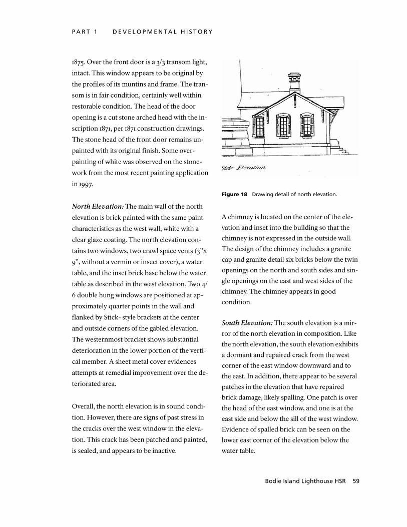
P A R T 1 D E V E L O P M E N T A L H I S T O R Y
http://crs.sero.nps.gov/historic/hsr/malu/e_sum
mary.htm
Bodie Island Lighthouse HSR 59
1875. Over the front door is a 3/3 transom light,
intact. This window appears to be original by
the profiles of its muntins and frame. The tran-
som is in fair condition, certainly well within
restorable condition. The head of the door
opening is a cut stone arched head with the in-
scription 1871, per 1871 construction drawings.
The stone head of the front door remains un-
painted with its original finish. Some over-
painting of white was observed on the stone-
work from the most recent painting application
in 1997.
North Elevation: The main wall of the north
elevation is brick painted with the same paint
characteristics as the west wall, white with a
clear glaze coating. The north elevation con-
tains two windows, two crawl space vents (3”x
9”, without a vermin or insect cover), a water
table, and the inset brick base below the water
table as described in the west elevation. Two 4/
6 double hung windows are positioned at ap-
proximately quarter points in the wall and
flanked by Stick- style brackets at the center
and outside corners of the gabled elevation.
The westernmost bracket shows substantial
deterioration in the lower portion of the verti-
cal member. A sheet metal cover evidences
attempts at remedial improvement over the de-
teriorated area.
Overall, the north elevation is in sound condi-
tion. However, there are signs of past stress in
the cracks over the west window in the eleva-
tion. This crack has been patched and painted,
is sealed, and appears to be inactive.
Figure 18 Drawing detail of north elevation.
A chimney is located on the center of the ele-
vation and inset into the building so that the
chimney is not expressed in the outside wall.
The design of the chimney includes a granite
cap and granite detail six bricks below the twin
openings on the north and south sides and sin-
gle openings on the east and west sides of the
chimney. The chimney appears in good
condition.
South Elevation: The south elevation is a mir-
ror of the north elevation in composition. Like
the north elevation, the south elevation exhibits
a dormant and repaired crack from the west
corner of the east window downward and to
the east. In addition, there appear to be several
patches in the elevation that have repaired
brick damage, likely spalling. One patch is over
the head of the east window, and one is at the
east side and below the sill of the west window.
Evidence of spalled brick can be seen on the
lower east corner of the elevation below the
water table.

P h y s i c a l D e s c r i p t i o n
60 National Park Service SERO
Figure 19 Photo of south elevation by U.S. Coast Guard, 1948.
There are two patched holes in the center of
the elevation below the water table and above
the inset in the wall. Earlier photos suggest
these patches mark the location of what appear
to be drain outfalls from the Oil Room. Mid-
20th century photos also indicate the location
of a box mounted to the south wall below the
water table. The brick shelf defining the inset
brick panel below the water table was partly
removed to accommodate the box sometime
between 1930 and 1948. A portion of a bracket,
likely part of the anchorage system for the box,
remains attached to the wall. The windows on
this elevation are 4/6 like those on the north el-
evation. However, the east window on the
south elevation has a metal screen on a wood
frame attached to the window frame. Also
present are five brackets for shutters that no
longer exist.
The chimney on the south elevation matches
the chimney on the north elevation but is lean-
ing noticeably to the west. A visual inspection
of the chimney by the structural engineer of
Hartrampf, Inc. suggests the lean is not due to
deterioration but was more likely produced in
the original construction, an interesting devia-
tion in craftsmanship from the quality of the
balance of the structure. At the time of the next
roofing and flashing related rehabilitation in
this area, the alignment and condition of the
chimney masonry at and just below the roof-
line should be further evaluated. There is no
evidence on the interior that this chimney is in
any distress. The crack on the interior side of
the chimney is likely due to early thermal ex-
pansion of the vent flue and does not appear to
be active. This flue was originally designed to
vent gasses from the building when oil stored in
the room was burned as a light source. The vent
is no longer used.
East Elevation: The east elevation is a contin-
uation of the painted brick, water table, and
inset band below the water table on the north
and south elevations. The banding on the Oil
House is terminated into the wall of the con-
necting Hall (H/100). The north side of the east
elevation contains a single crawl space vent of
the size and in a similar relationship to the wa-
ter table as on the north elevation, just below
the water table and centered in the wall.
Roof: The roof of the Oil House is a brown as-
phalt composition shingle of unknown age.
The earliest reference to the material of the
roof is in the 1977 National Register Nomina-
tion drafted by the North Carolina Heritage
Conservation and Recreation Service, which
refers to the roof as being asphalt shingle. No
reference to a roof replacement since then has
been located among the agencies charged with

P A R T 1 D E V E L O P M E N T A L H I S T O R Y
http://crs.sero.nps.gov/historic/hsr/malu/e_sum
mary.htm
Bodie Island Lighthouse HSR 61
the maintenance oversight of the Lighthouse.
While showing some age, the roofing appears
to be functioning satisfactorily. There were
originally no gutters or downspouts on the
building, and there are none now. The fascia
board on the Oil House appears to be in rea-
sonably good condition. The likely culprit
causing the damage to the ceilings below is the
flashing.
The flashing on the building is a problem. The
valleys are copper and appear to be function-
ing, but the southwest valley is in the
approximate location of an apparent leak in the
Oil Room (OH/102). The flashing at the chim-
neys appears to have had remedial repair with a
black mastic- type material and could well be
close to failing, if not already failing.
Summary Observations: The following sum-
marize the observations and issues identified
related to the exterior of the Oil House:
• Spalling of the brick was observed on the
Oil House. This is a concern due to the
potential for water to enter the building
from flooding and rising damp, given the
high water table in the area. See the Ulti-
mate Treatment and Use portion of this
report for recommendations.
• The condition of the roof framing, cur-
rently not accessible, should be examined
and fully documented at the next roof
replacement. Rotted members should be
replaced.
• There did not appear to be any notable
movement in the structure that merited
concern. Stress cracks observed all
appeared to be stable and not active.
• The flashing around the chimneys and in
the valleys appears, from visual observa-
tion on the underside, to require replace-
ment.
HALL CONNECTION
The Hall Connection (H/100) is a short corri-
dor between the Oil House and the Tower. This
space is defined by the door separating the hall
from the Oil House and the radial stairs leading
to the first level of the Tower.
Foundation: The original drawings of the Hall
Connection (H/100) indicate that the founda-
tion, shown to be brick resting on a stone
footing, extends down from 4’ to 6’ below
grade. All observable conditions suggest that
the foundation of the Hall Connection is
sound.
Structural System: The structural system for
this part of the structure is similar to the struc-
ture of the Oil House:
• A footing that extends some distance
below grade
• Load- bearing masonry walls
• Wood roof framing
• The floor supported by fill, possibly stone
fill, as suggested in the original drawings.
The structural systems appear in sound condi-
tion. However, the roof framing was not
accessible and, therefore, its condition could
not be verified. There are no sags or other ir-

P h y s i c a l D e s c r i p t i o n
62 National Park Service SERO
regularities in the roof ridge or decking,
common clues of damage to the wood roof
support system.
North Elevation: The north elevation of the
hall (H/100) contains one double- hung 4/6
window approximately centered in the wall. A
diagonal crack extending from the upper east
corner of the window and extending to the east
was patched and appeared dormant. A light-
ning protection cable penetrates the east jamb
of the window frame approximately in line with
the middle of the upper sash and extends verti-
cally to the ground. A National Park Service
staff member on site reported to have been told
that this cable was the original lightning pro-
tection cable. However, examination of historic
data does not support this speculation. The
original lightning protection system was the
stair, which was connected to the lightning rod
atop the ventilator ball at the top and to a cop-
per grounding rod driven into the ground near
the center of the Tower at the bottom, accord-
ing to Holland. When this method proved to be
dangerous to personnel at the Lighthouse, it
was changed, in 1884, to a cable running from
the light, down the center of the Tower, and
connected at the bottom to an iron plate bur-
ied in the ground. The location of the iron
plate is not known. It may be that this cable is a
remnant of the second lightning protection
system, as it runs along the interior wall of the
connecting hall at floor level with the Tower
and then along the perimeter of the floor in the
Tower, terminating at a connection to the bot-
tom stair newel.
The brick walls of this elevation are similar to
that described on the Oil House. Painted with
numerous coats of paint, the brick condition is
difficult to determine. However, the amount of
irregularity in the wall surface suggests the face
of the brick under the paint may be damaged.
The fascia board of the roof eave at this eleva-
tion was rotted and will require replacement.
This elevation contains a notable amount of
mildew on the painted brick surfaces, suggest-
ing both exposure to a significant and ongoing
amount of moisture and poor air circulation
and sun exposure, which, if improved, could
deter mildew growth.
South Elevation: The characteristics and con-
ditions of the south elevation are similar to
those on the north elevation except for the
following:
• No rotted fascia board on the eave of the
roof at this elevation was observed.
• A repaired crack in the masonry, patched
prior to the last painting, extending from
the upper east corner eastward, appears
dormant.
• There is less mildew on this elevation than
on the north elevation
• The window has been covered with ply-
wood to protect it from further deteriora-
tion.
Roof: The roof of the Hall Connection (H/100)
has a common ridgeline with the Oil House.
The roofing material is, as on the Oil House,
reddish brown asphalt composition shingles.
The primary flashing related to this roof is two

P A R T 1 D E V E L O P M E N T A L H I S T O R Y
http://crs.sero.nps.gov/historic/hsr/malu/e_sum
mary.htm
Bodie Island Lighthouse HSR 63
valleys where the roof ties into the roof of the
Oil House and step flashing at the junction with
the Tower. The flashing at the Tower appears
marginal in condition and may be contributing
to the infiltration of water into the Tower as ex-
hibited by peeling paint in the brick arched
ceiling area of the Tower at the connection with
the Hall (H/100).
Summary of Observations: The following
summarize issues and conditions of note in
considering restoration of the Hall between
the Oil House and Tower:
• Spalling of the brick was observed on the
Hall Connection (H/100). This is a concern
due to the potential for water to enter the
building from flooding and rising damp,
given the high water table in the area. See
the Ultimate Treatment and Use portion of
this report for recommendations.
• The condition of the roof framing, cur-
rently not accessible, should be examined
and completely documented at the next
roof replacement. Rotted members should
be replaced.
• There did not appear to be any notable
movement in the structure that merited
concern. All previous stress cracks appear
to be stable and not active.
• The flashing at the Lighthouse/Hall Con-
nection joint appears, from observations
on the interior, to be failing.
LIGHTHOUSE
Structural System: The Tower is load- bearing
masonry on a stone foundation.
Foundation: The foundation of the Tower is
described in A History of the Bodie Island Light
Station by Francis R. Holland, Jr. (1967) in
which he states that a pit 7’ deep was dug and
pumped during construction to keep it dry. In
the pit, a timber grillage, two courses of 6”x 12”
timbers, was placed. Large granite blocks, 18”
thick were placed on the grillage. On top of the
grillage blocks, courses of rubble blocking
weighing one to five tons were placed to raise
the foundation an additional 5’. Each course of
stone was grouted with hydraulic Portland ce-
ment. Overall, the foundation of the Tower
appears in very good condition.
Wall Structure - Base: The exterior course of
the base is split- faced granite with a cut band
around each piece except for the cap, which
has a smooth finish. The interior of the base,
behind the exterior cut stone, was rubble set in
cement.
Wall Structure - Brick: The Tower’s brick walls
taper from 2 ½ bricks thick at the top to 6 bricks
thick at the base as indicated on the original
drawings.
The drawings further suggest that there is an
interior course of veneer brick throughout the
Tower. It is unclear if and how the interior
course of brick is tied into the exterior, more
massive, assembly by other than mortar and the
characteristics of its cylindrical configuration.
Windows are offset vertically to avoid two win-
dows with overlapping vertical alignment.
Overall, the masonry structure appears sound.
No cracks in the exterior masonry were ob-
served from the ground using a 10x monocular.

P h y s i c a l D e s c r i p t i o n
64 National Park Service SERO
Figure 20 Drawing detail of Lighthouse base.
The Tower was last painted in 1997, which,
along with the number of previous paint layers,
may have masked conditions that cannot be
observed from the ground.
West Elevation: Being a symmetrical, tapered
cylinder, the basic characteristics of the Tower
are similar on each elevation. The overall char-
acteristics of the Tower exterior will be
discussed here, and conditions and character-
istics specific to the balance of the elevations
will be discussed under the presentation for
each of the other elevations.
According to the paint analysis, the strata of
finish on the exterior of the Tower includes:
Masonry: Overall, the masonry appears in good
condition. However, as was observed on the
exterior of the Oil House, there are areas of ir-
regularity in the masonry surface that suggest
that, over time, moisture has penetrated behind
the paint, primer, and sealer as a result of
flooding or rising damp, and, possibly, pro-
duced spalling.
Parge Coating: This strata is not visible from the
exterior but was documented in the paint anal-
ysis. The paint analysis refers to the Currituck
Beach Lighthouse as also having a parge coat-
ing (but never painted) similar to the Bodie
Island structure. A site visit was made to the
Currituck Beach Lighthouse to observe the
surface conditions. No parge or mortar- like
wash coating remained on that structure, likely
due to its erosion by the forces of local weather.
Resinous Oil- Based Sealer: This layer is not ex-
posed. The stratum of finish was analyzed and
addressed in the paint analysis. Its condition
and effectiveness in retarding moisture infil-
tration is unknown.
Paint Primer: This layer, like the sealer, is not
exposed and, like all the coating layers on the
tower, is examined in the paint analysis of the
structure. The condition and effectiveness of
this layer is unknown but is presumed to be
sound, given the age and condition of the cur-
rent exterior paint coating.
Paint Finish Coats: The existing exterior paint
coating was applied in 1997 by the United
States Coast Guard. This coating is, overall, in-
tact, with exceptions noted below.
The color scheme of the tower is of note. The
existing color scheme includes:
• Unpainted cut ashlar granite base except
for the top of the cut cap course, where the
vertical surface is painted white.
• Five approximately- equal alternating
bands of white and black starting with
white (band 1) above the unpainted base.
Bands are about 22’ wide.

P A R T 1 D E V E L O P M E N T A L H I S T O R Y
http://crs.sero.nps.gov/historic/hsr/malu/e_sum
mary.htm
Bodie Island Lighthouse HSR 65
• Black at the watch level and above with the
exception of the white window muntins at
the lantern level.
The placement of the five windows in the
Tower is notable. They are alternating so as to
not align, providing sufficient spacing between
them to retain structural integrity of the Tower
shaft. The windows are on the east and west
elevations of the Tower. The windows on the
west side are positioned in the black bands, 2
and 4. The windows are articulated by project-
ing brick surrounds further detailed by stone
window hoods, lintel corner stones, and key-
stones, all rusticated in texture with a smooth
cut band around their perimeter of about 1”.
Until about 1944, the stone window details
were not painted.
The upper three levels of the Tower are nota-
bly different from the zone of the elevation
between the base and the belt course of ma-
sonry at approximately the floor elevation of
the Watch Room. At and above the belt course,
cast iron features are introduced to the eleva-
tion. At the Watch Room level, the first level
above band 5, substantial cast iron brackets are
mounted to the wall of the Tower. These
brackets support the lower gallery above.
There are four brackets per quadrant of the
Tower’s circumference. A window is centered
in the Tower at quarter points on the north,
south, east, and west. The four brackets in each
Specific observations on the west elevation
What appeared as a dark stain or moisture was observed in this area. It was difficult to view this condition, but the condition was suffi-ciently noticeable to merit recording.
Stain or dampness in band three vertically aligned with the north corner of the window in band 4 and extended to that point. It had rained earlier in the day that these visual observations were made; therefore, the “stain or dampness” may have been of little or no significance. However, given the other obser-vations made on this and other elevations of the Tower, it is worth noting and monitoring.
What appears to be efflorescence on bands 1 and 2 to the north of the window in band 2.
A small spall area was observed at the area of the upper south corner of the window in black band 2. While not major, this observation sug-gests the likelihood of some moisture behind the brick in isolated areas.

P h y s i c a l D e s c r i p t i o n
66 National Park Service SERO
quadrant are spaced equally from the jamb of
one window to the jamb of the next adjacent
window.
The exterior of the Watch Room level is cur-
rently painted black, including the windows.
This may not have always been the case, based
on observations documented in the paint anal-
ysis. It may be that this zone, below the lower
gallery and above the black belt course at the
bottom of the structural cast iron brackets, was
a lighter shade. This is supported by the origi-
nal rendering of the Tower showing a lighter
shade than the darker bands that were ren-
dered as black in the original drawings.
However, it has been painted black since be-
fore 1932, according to the paint analysis.
A cast iron band the height of this level and
surrounding the tower between the lower and
upper gallery encases the level below the lan-
tern. From observation inside the Tower and
from the original drawings, the brick, it ap-
pears, may be two courses thick. It extends
above the thickened brick belt course at the
bottom of the watch level to the top of the level
below the lantern. The exterior of the brick
was not accessible. However, observations of
the iron banding revealed a generally horizon-
tal crack that extended from the south
quadrant of the west elevation well into the
south elevation of that level and material.
There was no evidence of a corresponding
condition in the brick; however, the full sur-
face of the interior brick was not accessible.
The galleries are cast iron. Refer to the struc-
tural evaluation, based on visual observation,
regarding the current structural condition and
carrying capacities of the galleries contained
later in this report. Clues of their condition in-
clude the following site observations:
• Some decorative components of the cast
iron brackets supporting the lower gallery
are missing parts. The on- site staff indi-
cated that some parts have fallen from the
Tower in recent times. The earliest record
of this occurrence is in the Alden and
Associates report of 1996. The loss of dec-
orative parts can be a clue to the potential
for deterioration in the balance of the
brackets.
• Observations from the Watch Room level
windows, located vertically in the middle
of the gallery brackets, indicated a consid-
erable amount of oxidation on and erosion
of the cast iron fittings and features of the
gallery brackets and underside of the
flooring.
• Some of the stanchions on the lower gal-
lery railing, as stated in the paint analysis,
are showing considerable deterioration. As
much as 30 percent of their cross section
has been lost to corrosive erosion.
The window muntins at the lantern level ap-
pear in sound condition. Attached to them on
the exterior are two sets of what appear to be
brass handles, presumably as grips for use
when it was necessary to be on the gallery to
maintain, inspect, or operate the Lighthouse.
The handles appear to be in very good condi-
tion. It is not known when they were installed.

P A R T 1 D E V E L O P M E N T A L H I S T O R Y
http://crs.sero.nps.gov/historic/hsr/malu/e_sum
mary.htm
Bodie Island Lighthouse HSR 67
North Elevation: Observed conditions specific
to the north elevation include:
• An area of mold or algae growth appears to
exist in the area of band 4 on this side of
the Tower.
• A lightning protection ground cable is
attached to the Tower on this elevation.
• At the base, generally in the middle cours-
ing of the cut granite base, there appears to
be leaching at the mortar joints. The char-
acteristics of the mortar are not known.
While the condition of the mortar appears
generally sound all around the base, the
leaching suggests some pressure from the
inside of the Tower base outward. One
possible cause is that, over time, the com-
bination of high water table and flooding
has pushed moisture up into the base, and
that those conditions and events have
resulted in leaching. The stone base, how-
ever, appears to be stable.
• The upper vertical surface of the base cap-
stone is inappropriately painted and should
be stripped.
South Elevation: Observed conditions spe-
cific to the south elevation include:
• There appears to be an efflorescence- type
action on this elevation similar to the
leaching identified above on the north ele-
vation.
• The upper vertical surface of the base cap-
stone is inappropriately painted and should
be stripped.
East Elevation: The east elevation is similar to
the other three elevations except that it con-
tains three windows. The three windows are in
the three white bands of the Tower, bands 1, 3,
and 5, and are of the same design and detailing
as the windows on the west side. Like the west
windows, the stone detailing of the window
hood and sill have been painted, though, in this
case, white to match the banding of the Tower.
Observed conditions specific to the east eleva-
tion include:
• Staining at belt course of brick, generally at
the floor level of the Watch Room. The
source is likely the cast iron brackets and
associated fittings in the vicinity of the belt
course.
• Earlier photographs reveal that a lightning
protection ground was installed at one time
on this elevation of the Tower. On the
south side of the three windows on this
elevation are a series of small areas of
deterioration generally extending from the
base of the lowest window to the middle of
the black band between the second and
third windows from the base. These con-
ditions deserve further evaluation from
closer range.
• The upper vertical surface of the base cap-
stone is inappropriately painted and should
be stripped.
Roof: The roof of the Tower is presently inac-
cessible and is historically and architecturally
significant. Most, if not all, of the original roof
structure appears intact when comparing site
observations with the original drawings. The

P h y s i c a l D e s c r i p t i o n
68 National Park Service SERO
roof material is shown on the 1871 drawings to
be made of 3/32” copper sheeting. There are no
records that it has ever been replaced. With the
limited amount of rain on the day of the site
visit for this report, there were no obvious leaks
in the roof and no signs of wholesale roof leaks
when viewed from the underside.
The crown piece with ventilator ball is a dis-
tinctive feature of the roof. As shown on the
original drawings, it includes several compo-
nents. Its spherical top, the ventilator ball,
supports a bronze, platinum- pointed pinnacle
of 3’- 10 ½ ” in height, the original lightning
protection. On the lower half of the copper
ventilator ball is a series of holes designed to
vent the lantern room when oil was the source
of fuel. Within the ventilator ball is a cylindrical
ventilator that works in tandem with the vent
holes in the sphere.
Interior Materials Finishes and Characteristics
The original drawings for the Tower illustrate in
considerable detail the original finish charac-
teristics of the Tower. An examination of the
drawings in relation to on- site observations of
the interior of the structures indicates the inte-
rior is substantially intact. The observations
documented herein are focused on modifica-
tions of details that have occurred to respond
to the requirements for maintenance and the
repair of deterioration. The three primary gen-
erators of change in the structures are moisture
infiltration, insect infestation, and changing
power sources and luminaries for the operation
of the light. The following Schedule of Finishes
catalogs the finishes and characteristics found
in the structure in the preparation of this
report.
Schedule of Existing Finish Characteristics - Floors & Walls
Ident. # Location Floor Walls
North South East West
Oil House
OH/100 Hall Marble Brick/ Paint Brick/Paint Door Door
OH/101 Work Room Wood Brick/Paint/Wainscoting
Cement/Paint
Brick/Paint/Wainscoting
Brick/Paint/Wainscoting
OH/102 Oil Room Marble Cement/Paint Brick/Paint Brick/ Paint Brick/ Paint
Hall
H/100 South Window
Marble/Granite
Brick/ Paint Brick/ Paint - Door
Lighthouse
LH/100 First Level of Tower
Marble/Granite
Brick/ Paint Brick/ Paint Brick/Paint Brick/Paint

P A R T 1 D E V E L O P M E N T A L H I S T O R Y
http://crs.sero.nps.gov/historic/hsr/malu/e_sum
mary.htm
Bodie Island Lighthouse HSR 69
LH/101 First Cast Iron Landing
Cast Iron Brick/ Paint Brick/ Paint Brick/Paint Brick/Paint
LH/102 Second Cast Iron Landing
Cast Iron Brick/ Paint Brick/ Paint Brick/Paint Brick/Paint
LH/103 Third Cast Iron Landing
Cast Iron Brick/ Paint Brick/ Paint Brick/Paint3 Brick/Paint
LH/104 Fourth Cast Iron Landing
Cast Iron Brick/ Paint Brick/ Paint Brick/Paint Brick/Paint3
LH/105 Fifth Cast Iron Landing
Cast Iron Brick/Paint1 Brick/Paint1 Brick/Paint Brick/Paint3
LH/106 Sixth Cast Iron Landing
Cast Iron Brick/Paint1 Brick/Paint2 Brick/Paint3 Brick/Paint1
LH/107 Seventh Cast Iron Landing
Cast Iron Brick/Paint1 Brick/Paint3 Brick/Paint3 Brick/Paint3
LH/108 Eighth Cast Iron Landing
Cast Iron Brick/Paint1 Brick/ Paint Brick/Paint Brick/Paint
LH/109 Watch Room Cast Iron Cast Iron Brick/Paint2 Brick/Paint Cast Iron
LH/110 Lantern Room
Cast Iron Granite / Cast Iron
Glass Glass Glass
LEGEND
Flooring Walls
Wood 3 ¼” Tongue & Groove Wood Flooring running East/West Brick Brick
Marble 12”x12”x1” Marble, Black/ White Checkerboard Paint/BK/GR Paint/ Black/Gray
Cast Iron Cast Iron Checker Plate Wainscoting Wainscoting/ See Detail
Granite Granite Steps Door Door & Transom
Open Open
Cement Cementitious Finish on Brick
Glass Glass
Cast Iron Cast Iron
Notes
1 Vertical Wall Crack, Patched, Inactive
2 Paint & Brick Spalling
3 Peeling Paint and/or Moisture Stains
4 Prismed Floor Grate

P h y s i c a l D e s c r i p t i o n
70 National Park Service SERO
Schedule of Existing Finish Characteristics - Ceilings, Moldings & Fixtures
Ident. #
Location Ceiling Moldings Fixture
Material Base Crown
Oil House
OH/100 Hall Wood 1 Paint/8” - 1
OH/102 Oil Room Wood 1 - Wood 1
OH/101 Work Room Wood 1 Wood Wood 1
Hall
H/100 South Window Wood 2 Paint/7” - -
Lighthouse
LH/100 First Level of Tower Cast Iron/Open Paint/GR/8” Corbel 2N
LH/101 First Cast Iron Landing Cast Iron/Open Paint/BK/4” Corbel 2S
LH/102 Second Cast Iron Landing Cast Iron/Open Paint/BK/4” Corbel -
LH/103 Third Cast Iron Landing Cast Iron/Open Paint/BK/4” Corbel 2N
LH/104 Fourth Cast Iron Landing Cast Iron/Open Paint/BK/5” Corbel -
LH/105 Fifth Cast Iron Landing Cast Iron/Open Paint/BK/5” Corbel 2N
LH/106 Sixth Cast Iron Landing Cast Iron/Open Paint/BK/4 ½” Corbel -
LH/107 Seventh Cast Iron Landing Cast Iron/Open Paint/BK/5” - 2NE
LH/108 Eighth Cast Iron Landing Cast Iron Paint/BK/4” - 2NE
LH/109 Watch Room Cast Iron4 - - 2N
LH/110 Lantern Room - - - -

P A R T 1 D E V E L O P M E N T A L H I S T O R Y
http://crs.sero.nps.gov/historic/hsr/malu/e_sum
mary.htm
Bodie Island Lighthouse HSR 71
LEGEND
Ceiling Base
Wood 1 3 ½” Beaded Board running East/ West P/ __” Black Paint on Masonry/ Inches in ht.
Wood 2 4” Beaded Board Running East/West Wood Wood Assembly
Corbel 4 brick Corbel, See Detail
Cast Iron ½ Cast Iron Landing Crown
Open ½ Open to accommodate Stair Wood Wood Crown Type 1/ See Detail
Fixtures (Note: location is indicated by direction)
1 Fixture 1/See Detail
2 Fixture 2/See Detail
Notes
1 Vertical Wall Crack, Patched, Inactive
2 Paint & Brick Spalling
3 Peeling Paint and/or Moisture Stains
4 Prismed Floor Grate

P h y s i c a l D e s c r i p t i o n
72 National Park Service SERO
Molding & Light Fixtures
Ceiling Molding Type 1 Fixture 1 Fixture 2
Door Elevations
Elevation 1 Elevation 2 Elevation 3 Elevation 4 Elevation 5

P A R T 1 D E V E L O P M E N T A L H I S T O R Y
http://crs.sero.nps.gov/historic/hsr/malu/e_sum
mary.htm
Bodie Island Lighthouse HSR 73
Door ScheduleId
ent.
#
Loca
tio
n
Wid
th
Hei
gh
t
Pro
file
Tran
som
Mat
eria
l
Fin
ish
Hea
d
Jam
b
Thre
sho
ld
Har
dw
are
Ori
gin
al
Oil House
OH/D1 Front Door
3'- 3 1/4” 7'- 5 ½” 2 1 Wood Painted 2 2 1 Not Original
No
OH/D2 OH/100 to OH/102
2'- 11 ½” 7'- 6” 2 1 Wood Painted 1 1 2 Not Original
Yes
OH/D3 OH/100 to OH/101
2'- 11 ½” 7'- 6” 1 1 Wood Painted 1 1 2 Mortise Yes
OH/D4 OH/100 to H/100
3'- 3” 7'- 5 ¼” 1 1 Wood Painted 3 3 3 Mortise Yes
Hall
No Doors
Lighthouse
LH/D1 Lower Gallery Exteror Door
2'- 10” 6'- 8 ½” 3 - Iron Painted 4 1 4 4 1 2 Yes
LH/D2 Lower Gallery Interior Door
2'- 3” 6'- 8 ¼” 4 - Wood Painted 4 1 4 4 Mortise Yes
LH/D3 Watch Room Door
2'- 2 ½” 6'- 8 ½” 5 - Wood Painted - - 5 Not Original
No
LEGEND
Notes
1 Head detail matches jamb detail
2 Iron slide bolt on face of door

P h y s i c a l D e s c r i p t i o n
74 National Park Service SERO
Door Profiles
Profile 1 Profile 2
Profile 3
Profile 4 Profile 5
Door Head/Transom Details
Head 1 (Head 2 similar) Head 3 Transom Muntin

P A R T 1 D E V E L O P M E N T A L H I S T O R Y
http://crs.sero.nps.gov/historic/hsr/malu/e_sum
mary.htm
Bodie Island Lighthouse HSR 75
Door Jamb Details
Jamb 1 Jamb 2 Jamb 3
Jamb 4 (Head 4 similar)
Door Threshold Details
Threshold 1 Threshold 2 Threshold 3
Threshold 4 Threshold 5

P h y s i c a l D e s c r i p t i o n
76 National Park Service SERO
Window Elevations
Oil House- Exterior Window Elevation
Oil House- Interior Window Elevation
Tower - lh/w1 & w2 Tower- lh/w3 & w4 Tower- lh/w5 Tower - lh/w6, w7, w8, & w9

P A R T 1 D E V E L O P M E N T A L H I S T O R Y
http://crs.sero.nps.gov/historic/hsr/malu/e_sum
mary.htm
Bodie Island Lighthouse HSR 77
Window ScheduleId
ent.
#
Loca
tio
n
Wid
th
Hei
gh
t
Typ
e
No
. Lig
hts
Mat
eria
l
Fin
ish
Hea
d
Jam
b
Sill
Oil House
OH/W1 Southwest Window
2'- 3 1/2” 2'- 6 1/4”
5'- 10”1 6'- 6 1/2”
Fixed/ Double Hung
4/6 Lts.
Wood Painted 1 1 2
OH/W2 Southeast Window
2'- 3 1/2” 2'- 6”
5' 10”1 6'- 6 3/4”
Fixed/ Double Hung
4/6 Lts.
Wood Painted 1 1 2
OH/W3 Northwest Window
2'- 3 1/2” 2'- 4 3/4”
5'10”1
6'- 7 1/2”Fixed/ Double Hung
4/6 Lts.
Wood Painted 1 1 1
OH/W4 Northeast Window
2'- 3 1/2” 2'- 4 3/4”
5'10”1
6'- 7 1/2”Fixed/ Double Hung
4/6 Lts.
Wood Painted 1 1 1
Hall
H/W1 South Window
27- 1/2” 5'- 10” Fixed/ Double Hung
4/6 Lts.
Wood Painted 1 2 3
H/W2 North Window
27- 1/2” 5'- 10” Fixed/ Double Hung
4/6 Lts.
Wood Painted 1 2 3
Lighthouse
LH/W1 Level 2/3 East Window
3'- 2” 9'- 5 1/4” 9'- 11”2
Fixed/ Casement
4/10 Lts.
Wood Painted 2 3 4
LH/W2 Level 4 West Window
3'- 2” 9- '6” 9'- 11”2
Fixed/ Casement
4/10 Lts.
Wood Painted 2 3 4
LH/W3 Level 5/6 East Window
3'- 2” 8'- 9 1/4” 9'- 3”2
Fixed/ Casement
4/10 Lts.
Wood Painted 2 3 4
LH/W4 Level 7 West Window
3'- 1 1/2” 8'- 10”3
9'- 3 1/4”Fixed/ Casement
4/10 Lts.
Wood Painted 2 3 4
LH/W5 Level 8/9 East Window
3'- 2” 7'- 4”3 Fixed/ Casement
4/10 Lts.
Wood Painted 2 3 4

P h y s i c a l D e s c r i p t i o n
78 National Park Service SERO
LH/W6 Level 10 East Window
2'- 2 1/4” 7'- 6 1/2” Fixed 4/8 Lts.
Wood Painted 3 4 5
LH/W7 Level 10 South Window
2'- 2 1/4” 7'- 6 1/2” Fixed 4/8 Lts.
Wood Painted 3 4 5
LH/W8 Level 10 West Window
2'- 2 1/4” 7'- 6 1/2” Fixed 4/8 Lts.
Wood Painted 3 4 5
LH/W9 Level 10 North Window
2'- 2 1/4” 7'- 6 1/2” Fixed 4/8 Lts.
Wood Painted 3 4 5
LEGEND
Notes
1 Exterior window dimension
2 Height of window at crown of arch
3 Height of window at spring of arch

P A R T 1 D E V E L O P M E N T A L H I S T O R Y
http://crs.sero.nps.gov/historic/hsr/malu/e_sum
mary.htm
Bodie Island Lighthouse HSR 79
Window Jamb Details
Jamb 1 Jamb 2
Jamb 3 Jamb4
Window Head Details
Head 1 Head 2 Head 3

P h y s i c a l D e s c r i p t i o n
80 National Park Service SERO
Window Sill Details
Sill 1 Sill 2 Sill 3
Sill 4 Sill 5
Muntin Details
Muntin 1 Muntin 2 Muntin 3

P A R T 1 D E V E L O P M E N T A L H I S T O R Y
http://crs.sero.nps.gov/historic/hsr/malu/e_sum
mary.htm
Bodie Island Lighthouse HSR 81
Summary Description of Interior Conditions
OIL HOUSE
Hall (OH/100)
Floor: The 12”x12” black and white marble tile is
set to produce a diamond pattern in the space.
The marble tile is typical of the Oil Room in the
Oil House, the Connecting Hall and the first
level of the Tower and is likely 1” thick as was
observed in the Light Tower. A 5” white marble
band surrounds the diamond pattern in the
floor.
Walls: The plaster on masonry walls have a
smooth finish and are painted. Generally, the
plaster is in sound condition.
Ceiling: The ceiling is arched and finished with
tongue- and- groove boards with one bead on
the tongue side. There is one 4” wide board just
south of center of the ceiling, while the prevail-
ing board width is 3 ½”. The ceiling is in good
condition.
Base: The base is painted on the wall up to a
height of 7” in black.
Crown: No crown molding exists in this room.
Fixture: Light fixture Type 1 is affixed to the
ceiling of this room.
Other Features: None identified.
Figure 21 Oil House, Hall (OH/100)
Work Room (OH/101)
The Work Room finish merited a more refined
treatment than the Oil Room. Given the indus-
trial functions of the Oil Room, it would have
been impractical to finish it with wainscot and
wood floors. The Work Room, on the other
hand, could provide more comfortable sur-
roundings for the Keeper and his Assistants
who used it.
Floor: The floor in this room is wood and is in
sound condition. According to the paint analy-
sis and Coast Guard maintenance reports, the
floor and floor framing were partly replaced in
1976 due to termite damage.

P h y s i c a l D e s c r i p t i o n
82 National Park Service SERO
Walls: The north wall of this room contains the
fireplace and windows. The walls in the Work
Room have different treatments. The south
wall is brick with a cementitious finish. The
other three walls are painted brick. All walls in
this room have a wainscot with a chair rail cap
at 3’- 8 ¾”.
Ceiling: The ceiling in this room is tongue-
and- groove, single bead board 3 ½” wide run-
ning east and west. The ceiling material appears
in good condition overall. This ceiling may
have been the one repaired by the Coast Guard
in late 1986 due to termite damage.
Trim: The wainscot is illustrated in the detail
attached to the finish schedule. An examination
of the details of the existing wainscot indicates
trim that is different from that suggested in the
original drawings, raising some question that
one of the following may be the case:
• the wainscot may not be original, or
• parts were altered in the past, or
• the original wainscot was not built as indi-
cated on the drawings.
It may be that the wainscot was included in the
repairs undertaken by the Coast Guard in late
1986 that were the result of termite damage.
Base: The base in this room is wood and, like
the wainscot, does not match the profiles
shown on the original drawings. It may also
have been repaired due to termite damage in
1986.
Crown: The crown molding in this room is a
two- piece assembly as illustrated in the finish
schedule and appears in good condition.
Fixture: An industrial metal shaded fixture
mounted to a junction box is on the ceiling of
this room. Its date of installation is not known.
Fireplace: The fireplace in the north wall of this
room is original, including the mantle and sur-
round, and is in good condition. The original
stone mantle cap is in place. According to the
paint analysis, the mantle surrounds and cap
have always been painted. Missing paint at the
bottom of the surrounds should not be mis-
taken for the shadow of a past base as one was
never installed according to the paint analysis.
Shadow of Past Shelving: There is evidence of
bracketed shelving or cabinets on the east and
west walls of this room. The 1871 drawings de-
fine the characteristics of this shelving.
Oil Room (OH/102)
The Oil Room has seen the most change of any
of the spaces in the structure. This is due to the
fact that the conversion from oil to electricity as
a power source for the light has been the single
most significant change in the history of the
building. Given that the function of the Oil
Room has been to support the power source
for the light, it has realized the most change.
Floor: The floor in the Oil Room is 12”x12’ mar-
ble in a pattern to match the pattern described
in the hall. Inserted in the floor are two areas of
concrete where the tile was removed and
equipment mounted in the past to support

P A R T 1 D E V E L O P M E N T A L H I S T O R Y
http://crs.sero.nps.gov/historic/hsr/malu/e_sum
mary.htm
Bodie Island Lighthouse HSR 83
power- generation. Like the Hall (OH/100), a 5”
band of white marble surrounds the square tile
floor pattern.
Walls: The painted brick walls are generally in
good condition. The walls on the east and west
side of the room accommodate cabinets and
benches. The north wall is brick with a cemen-
titious finish. The south wall is substantially
filled with the fireplace and the two windows.
Ceiling: The single bead board ceiling appears
in sound condition except for the deteriorated
area in the northwest corner of the room.
Base: There is no base in this room.
Crown: The crown profile is a two- piece trim
at the joint between the wood ceiling and plas-
ter walls. Overall, the trim appears in sound
condition.
Fixture: There is an industrial metal shade fix-
ture mounted to a junction box in the ceiling of
this room. Its date of installation is not known.
Other Features: There are several features of
note in this room. They include:
East and West Walls
• Butt Shelf Wall: The cast iron butt shelves
held the oil drums during the period when
oil was the power source for the light. The
original drawing for these shelves, Plate
VII, calls out the shelving as 155 lb. and the
iron support below as 140 lb. Phoenix T-
iron. The shelves are in place and in good
condition.
• Casework above Butt Shelf with Ladder:
The wood casework originally installed
above the cast iron butt shelving remains in
place, including the metal rails for the steel
ladders (based on the 1871 construction
documents) that were not observed on site.
Overall, the casework is in good condition.
North Wall
• Electrical Panel and Backboard: The north
wall of the room, east of the door, contains
a plywood backboard and an electrical
panel supporting the power supply to the
electric lamp at the top of the Tower.
South Wall
• Fireplace: The fireplace is original, includ-
ing the mantle and surround, and is in good
condition. Of particular note is a hole in
the upper part of the fireplace, above the
mantle that is often where a flue for a
wood- burning stove might have been
installed. However, an examination of the
original drawings indicates that the open-
ing in the chimney was to accommodate a
ventilator for handling and managing
fumes from the oil stored in the room.
There is no flue pipe connected to the hole
in the chimney at this time. The original
stone mantle cap is in place. According to
the paint analysis, the mantle surrounds
and cap have always been painted.
• Shelving: The south wall of this room
accommodated a workbench in front of the
window with casework to the east and west
side of each window respectively. These

P h y s i c a l D e s c r i p t i o n
84 National Park Service SERO
features do not exist at this time but were
presumably installed to address the opera-
tional requirements of an oil- fired lamp.
Connecting Hall (H/100)
Floor: The marble floor, identical in layout and
treatment to that found in the Oil House, is in
sound condition. A 1 ½” white marble band
separates the square tile pattern from the wall
on the north and south side of the room.
Walls: The painted brick walls exhibit peeling
paint and evidence of mildew. A potential
cause for this condition is the fact that a signif-
icant part of the north and south walls in the
room are inside the base of the Tower. The
mildew observed in this room supports the
conclusion that rising damp and flooding is
contributing to the leaching in the exterior
stone base, which may remain damp for long
periods of time, if not constantly.
Ceiling: The ceiling in this room is 4” tongue-
and- groove single bead board similar to the
single 4” ceiling board identified in the Hall of
the Oil House. The ceiling is, overall, in good
condition. At the east end of the Hall, the wood
ceiling terminates, and brick arches support the
Tower wall at the opening. Peeling paint was
observed in this area, suggesting the potential
that failure has occurred in the flashing where
the Hall roof connects to the Tower.
Base: There is no base in this room. However,
the suggestion of a base is painted on the north
and south walls to a height of 7”.
Crown: There is no crown molding in this
room.
Fixture: There is no light fixture in this room.
Conduit for Lamp Power: A significant feature
in this room is the conduit that traverses from
the electrical panel in the Oil Room of the Oil
House through the Hall and into the Tower,
where it ascends the Tower wall to the panel in
the Watch Room at the top of the Tower. A
portion of the brick at the intersection of the
Tower wall and the Hall wall at the top of the
stairs from the Hall to the Tower has been re-
moved to accommodate the turn of this
conduit from the Hall into the Tower.
LIGHTHOUSE
The Light Tower is, effectively, four rooms: the
main shaft, the Service Room, the Watch
Room, and the Lantern Room. However, given
that there are specific conditions to be noted at
and between each landing in the Tower, each
landing was considered a room for purposes of
documenting conditions in the Tower.
Stairs: Since the stairs are common to all levels
of the Tower, they are addressed here to best
present their condition and characteristics. The
original drawings document the characteristics
of the stairs in great detail. The Tower stairs
and landings (except for the first level which is
on fill with marble and stone flooring) are cast
iron. There are five cast iron components asso-
ciated with each tread (see Plate XI. of the 1871
construction documents), which are cast iron
with an open- checked plate walking surface.

P A R T 1 D E V E L O P M E N T A L H I S T O R Y
http://crs.sero.nps.gov/historic/hsr/malu/e_sum
mary.htm
Bodie Island Lighthouse HSR 85
Figure 22 Plate XI, 1871 Drawings.
The landings are cast iron plate with diamond
pattern on the walking surface and an integral
reinforcing grid on the underside and are sup-
ported by a cast iron I- beam at the diameter
edge of the landing.
The focus of this assessment is to identify the
number of treads on each level and the condi-
tions that deserve attention. The deteriorated
conditions noted in the following schedule are
based primarily on visual observation of dam-
aged treads. There may be other conditions of
damaged cast iron components that deserve
Schedule of Stair Treads & Conditions
Section# of Treads
Damaged Treads
Flight 1 1 - 25 19, 23, 24, 25
Flight 2 26 - 50 46, 47
Flight 3 51 - 72 71
Flight 4 73 - 94 82, 84, 85
Flight 5 95 - 114 -
Flight 6 115 - 132 -
Flight 7 133 - 149 -
Flight 8 150 - 179 169
Flight 9 180 - 196 186, 188, 192, 193
Flight 10 197 - 205 -

P h y s i c a l D e s c r i p t i o n
86 National Park Service SERO
repair or replacement that have been obscured
by successive coats of paint.
Base Level of Tower (LH/100)
The base level of the Tower is approximately
9’- 9” above the prevailing grade and 7’- 8”
above the finished floor of the Oil House and
Connecting Hall (H/100). The five treads lead-
ing from the intermediate level of the room to
the main level are granite. The upper level of
the stairs is protected by an ornamental cast
iron railing (See Plate IX of the 1871 Construc-
tion Documents, “Plan of Guard Railing at
Entrance Steps”).
Floor: The floor of this level of the tower is pri-
marily marble of alternating black and white.
The marble squares, however, are not set at the
same angle as those in the Oil House and Con-
necting Hall (H/100). The curved steps on the
east side of the room are granite with a granite
wall containing the inside of the steps.
Walls: The walls are painted brick, as is the case
throughout the Tower. Overall, the walls are in
good condition.
Ceiling: The ceiling of each level in the Tower is
the underside of the cast iron landing system
above. These are painted black. Overall, the
under side of the cast iron landing appears to
be in good condition.
Base: There is no applied base in the Tower.
However, there is a painted base, the charac-
teristics of which are cataloged in the Finish
Schedule.
Crown: While there is no crown molding in the
traditional sense, at the joint between the
Tower and each landing, a four- brick corbel-
ling exists to support the landing at the Tower
side. Overall, this detail appears in good
condition.
Fixture: The Type 2 fixture, a jelly- jar type in-
dustrial fixture, is surface mounted on the
north wall. This is typical of the fixtures in the
Tower. The locations of the fixtures in the
Tower are indicated in the finish schedule.
Other Features:
Security Fence and Door: A recent introduction
to the Tower on the lowest level is a chain- link
security fence and padlocked door installed in
1985 to prevent unwanted entry to the Tower
stairs. This is may be considered a non- con-
tributing feature that could be removed once
the use and management program for access to
the Tower is in place. It was installed to prevent
access by National Park Service visitors to the
Tower and is not part of any modifications re-
lated to the production or maintenance of the
light. Some floor and wall damage will have to
be repaired in this area if the fence is removed.
Well: In the center of the ground level is a de-
pressed well approximately 30” deep protected
by an original cast iron railing 38” high. The
well is constructed of cast iron, with a cast iron
wall and cast iron floor, the entire assembly be-
ing painted black. The well and railing are in
sound condition. The well was reportedly con-
structed to receive weights used in the
operation of a mechanism that would allow the

P A R T 1 D E V E L O P M E N T A L H I S T O R Y
http://crs.sero.nps.gov/historic/hsr/malu/e_sum
mary.htm
Bodie Island Lighthouse HSR 87
Figure 23 Well.
light to “flash.” However, the mechanism was
never installed, and, thus, the well was never
used as intended in the original design.
Electrical Conduit: Extending into the room
from the hall, the electrical conduit carrying
the cables that power the lamp is recessed into
the corner of the wall of the Tower as it turns
south to run horizontally to the center of the
south wall where it turns up to the upper level
of the Tower. There is also conduit on the
south wall to provide service to the light fix-
tures. There was no evidence of conduit
encased in the masonry walls. If there is any
concealed conduit, it is likely above the wood
ceiling in the adjacent hall.
Dedication Plaque: A marble dedication plaque
is mounted on the archway facing the center of
the Tower (see picture). There are three points
of note regarding this plaque. First, the spelling
of “Body” is an early spelling of the name, thus
suggesting an early fabrication and installation
Figure 24 Dedication Plaque.
of the plaque. The second point of note is that
the 1871 construction documents do not show a
plaque, suggesting one was designed, fabri-
cated, and installed in an exercise separate
from the original construction. Thirdly, this is
not the first plaque erected. The original plaque
listed the members of the Lighthouse Board
and the date at the time the construction of the
Bodie Island Lighthouse was begun. An image
of the drawing for the original plaque is found
in the Chronology of Development and Use
portion of this report. The drawing indicates
that the location of this plaque is also the loca-
tion of the installation of the first plaque. The
current plaque is in excellent condition, but has
some overpainting of white, the result of appli-
cations of paint to the wall to which it is affixed,
that should be removed.
Tower Levels 1 – 7 (LH/101- LH/107)
Floors: From this level to the Watch Room
level, the flooring is similar: a half- circle, cast
iron floor. The flooring appears in good con-

P h y s i c a l D e s c r i p t i o n
88 National Park Service SERO
dition. Like the stairs, the cast iron, non- slip,
diamond- pattern flooring is documented in
some detail in the original drawings.
Walls: The walls are painted brick. See Finish
Schedule for specific masonry conditions
identified.
Windows: The windows, though conforming to
the original window configuration, were in-
stalled in 1997 with hardware that is not
historic. The granite window stools were
painted black in 1997. According to the paint
analysis, the window ledges, historically, were
painted. Black was the original color, but they
were also painted brown and red- brown over
the years. However, the paint layer prior to the
1997 painting was black.
Ceiling: Underside of the cast iron landing
above, painted black.
Base: Painted; see Finish Schedule.
Crown: Though there is no crown molding in
the traditional sense, at the joint between the
Tower and each landing, a four- brick corbel-
ling exists to support the landing at the Tower
side. Overall, this detail appears in good
condition.
Fixture: See Finish Schedule.
Other Features: None identified.
Tower Level 8 / Service Room (LH/108)
Floor: The floor in the Service Room is cast
iron, diamond- pattern plating the full diameter
of the Tower at this level except for the curved
opening to accommodate the stairs from the
level below.
Walls: Cast iron paneling covers the masonry
on the north wall. The stair well from below is
enclosed by cast iron plating as well on the west
side.
Ceiling: The ceiling of the service room is the
underside of the grating of level 9. The grating
is in good condition.
Base: There is no base in this room, painted or
otherwise.
Crown: There are no crown molding features
in this room.
Fixture: There is a Type 2 light fixture mounted
on the northeast side of the room.
Other Features: None identified.
Tower Level 9 / Watch Room (LH/109)
Floor: The floor of the Watch Room is cast iron
grating, fully detailed in the original drawings.
It is in good condition.
Walls: The walls of the room are cast iron on
the east and west and, otherwise, painted
masonry.
Ceiling: The ceiling of this space is the under-
side of the flooring for the lantern level above.
A special feature of the perimeter cast iron
“ceiling” is a number of round inserts of pris-
matic glass designed to provide light to the

P A R T 1 D E V E L O P M E N T A L H I S T O R Y
http://crs.sero.nps.gov/historic/hsr/malu/e_sum
mary.htm
Bodie Island Lighthouse HSR 89
Figure 25 Watch Room ceiling insert made of prismatic glass.
Watch Room level below the lantern, much like
the deck prisms of ships. A number of the glass
prisms are missing. The cast iron grating and
lens pedestal appear in sound condition. On
the southwest side of the Watch Room is a pen-
etration in the ceiling for a vent for earlier coal
heat at that level. This source of heat has been
abandoned.
Base: See Finish Schedule.
Crown: None.
Fixture: Type 2 on north wall.
Other Features:
Lens Pedestal: The cast iron pedestal that sup-
ports the lens and light positioned in the center
of the room is supported by the cast iron floor
and framing below. The original manufacture’s
brass plaque, in French, is mounted on the post
Figure 26 Lens pedestal, original manufacturer’s brass plaque.
of the pedestal. The pedestal is in good
condition.
Electrical Panel: An electrical panel located on
the west wall is served by the main panel on the
north wall of the Oil Room.
Tower Level 10 / Lantern Room (LH/110)
Floor: The floor of the Lantern Room is the
grating in a perimeter ring around the lens
containing the inserts of prismatic glass. The
floor inside the lens is cast iron diamond plate,
typical of the floors at the Tower levels. The
floor, except for missing glass prisms in the
grating, appears in good condition.
Walls: The walls of this room are glass in cast
iron muntins the full circumference of the
room. There are two horizontal muntins in the
window framing structure. No visually notable
deterioration of structural concern was
observed.

P h y s i c a l D e s c r i p t i o n
90 National Park Service SERO
Ceiling: The ceiling of this room is the under-
side of the roof. There were no noticeable leaks
or signs of deterioration in the ceiling area,
though not all of the roof area was visible due
to the size and presence of the hood feature
described below.
Base: There is no base in this room
Crown: There are no crown molding features
in this room.
Fixture: The fixture in this room is the light. It is
a two bulb “Carlisle & Finch #44768” fixture.
While it was not lit the evening of the site visit,
there were no obvious signs of physical damage
to the fixture and lighting apparatus. Some
components of the original assembly to receive
and support the earlier oil reservoirs remain.
Other Features:
Lantern Hood: The lens hood is a feature re-
maining from the days of oil burning lamps.
This feature appears substantially intact but,
evidenced by the dents in it, may have been
moved or removed from time to time to access
the ventilation apparatus above.
Lens: The lens is a first order Fresnel lens held
in position by a brass and iron frame. There are
five distinct sections of the lens defined by the
position and configuration of the prisms. Ex-
cept for a few chipped prisms and one missing
prism in the second tier from the top of the
southeast quadrant of the lens, the lens appears
Figure 27 First order Fresnel lens.
in sound condition. The frame exhibits a lim-
ited amount of oxidation in some parts of the
cast iron frame. The bronze components of the
lens frame appear in good condition.
Structural Evaluation
The structural evaluation consisted of a visual
inspection of the subject structures that could
be conducted without benefit of removing his-
toric fabric or constructing scaffolding around
the Tower, as well as a review of the following
previously- completed evaluations, copies of
which were provided by the National Park
Service:
“Bodie Island Lighthouse Inspection Report,”
by the United States Corps of Engi-
neers for the United States Coast
Guard, 1989.

P A R T 1 D E V E L O P M E N T A L H I S T O R Y
http://crs.sero.nps.gov/historic/hsr/malu/e_sum
mary.htm
Bodie Island Lighthouse HSR 91
“Bodie Island Lighthouse, Dare County, N.C.
Report of Structural Conditions,” by
Alden and Associates, 1996.
Report of the International Chimney Corpora-
tion regarding structural and safety
concerns at the Bodie Island Light-
house, 2000.
In general, the observations of Hartrampf, Inc.
concur with previous evaluations, noting that
structural deterioration is progressing, and the
cost of remediation is increasing. One feature
of the Tower which has been of concern since it
was first reported in 1981 has been the vertical
cracking of the interior face brickwork, which
extends from the fourth through the seventh
levels. This may even be the cracking noted by
the District Engineer in 1877, who reported
“very slight” vertical cracks running from the
second landing to the seventh and attributed
them to stress from lightning strikes. 209 These
cracks do not appear to extend to the exterior
of the Tower. The finding is that one of the
cracks is inactive, that is, not getting worse, and
one of the cracks is still active, as evidenced by
past repair work that is currently failing. Since
1989, several reports have postulated possible
causes of these cracks. In 1989, the U.S. Corps
of Engineers suggested that the cracks were
caused by the combined effects of corrosion of
the support beams and thermal expansion of
the wall, though they did not feel that this com-
promised the structural integrity of the wall at
that time. The Coast Guard inspector in 1992
stated that he felt that the cracks in the bricks
had weakened the I- beam anchor points for
the Watch Room landing, making the structure
unsafe for maintenance personnel. The Alden
and Associates report in 1996 suggested that
cracking was due to severe windloading and
that the structural integrity of the tower could
be in doubt.
The cause of the cracks is not settlement, a
cause suggested by the Coast Guard inspector
in his 1992 report on the condition of the
Lighthouse.210 Settlement would be evidenced
by corresponding cracks in the foundation,
and the cracks do not originate at or propagate
from the base of the Tower as they would if
settlement was the problem. The location and
direction of the cracks indicate that windload-
ing, such as was suggested by Alden and
Associates in 1996,211 is also not the cause.
Cracks caused by flexural stresses from lateral
loads on a vertical cylinder, which the light-
house is, would have a horizontal or slightly
diagonal pattern, not a vertical pattern such as
exists at Bodie Island. The findings of Har-
trampf, Inc. on the cause of these cracks and
their importance to the structural integrity of
the Tower agree with those of the U.S. Corps of
Engineers. Corrosion of the steel beams, the
corresponding expansion stresses on the sur-
rounding mortar, and thermal expansion and
contraction are the likely causes of the cracks.
Subsequent moisture infiltration is causing ex-
pansion and deterioration of the mortar
209. Holland, p. 44.
210. “Bodie Island Light (LLNR 505) Report for Group Cape Hatteras, aNT, Kennebec,” in papers of the Shore Maintenance Detachment, Civil Engineering Unit, United States Coast Guard, Cleveland, Ohio, 1992.
211. Alden and Associates, 1996, p. 7.

P h y s i c a l D e s c r i p t i o n
92 National Park Service SERO
surrounding the bricks. This condition, if
properly addressed, using a deep- penetration
mortar repair, should not undermine the struc-
tural integrity of the Tower. Hartrampf found
no indication that the I- beam support had de-
teriorated significantly since the last repair. If
necessary, the mortar surrounding these mem-
bers can be repaired using the same deep-
penetration method as that suggested for the
repair of the brickwork.
Following are details of the findings of the
Hartrampf, Inc. structural inspection and eval-
uation. Issues not directly related to the
structural integrity of the Tower and Oil House,
such as windows and hardware, are addressed
elsewhere in this report.
OIL HOUSE
The Oil House provided limited access to
structural elements. There was no access to the
under side of floor or to the roof framing. Some
of the architectural finish elements have evi-
dence of rot. This implies that structural
elements behind most likely will have rot as
well. Specific locations include:
• Ceiling of the Oil Room
• Wall behind northern side of lower cabinet
shelf of west wall in Oil Room
• Wall behind southern side of upper cabinet
shelf of east wall in Oil Room
• Ceiling of the Work Room
Preservation efforts in these areas should in-
clude removal of damaged materials only and
replacement to match existing. There was no
Figure 28 South chimney above the Oil Room.
evidence on the exterior of roof framing failure,
which might be detected by sagging of the roof
at the ridgeline or other framing members.
The southern chimney, above the Oil Room,
has a noticeable lean to it above the roofline.
Concern has been expressed that the chimney
may be unstable. However, there is no apparent
evidence of distress to the brickwork. Historic
photographs from the 1890s suggest that this
chimney was leaning at that time, implying that
the chimney may have been originally built out
of plumb. The tilt has had no apparent adverse
effects on the structural integrity of the chim-
ney. Therefore, recommendations in this report
do not include rebuilding or straightening of
the chimney.
LIGHT TOWER - EXTERIOR
Some of the exterior granite stonework shows
efflorescence and a discharge of mortar mate-
rial at the joints. These joints do not appear to
be failing, and the stonework does not appear
to be unstable in any way. There is no visible

P A R T 1 D E V E L O P M E N T A L H I S T O R Y
http://crs.sero.nps.gov/historic/hsr/malu/e_sum
mary.htm
Bodie Island Lighthouse HSR 93
evidence of movement of the stones. Past sug-
gestions that the foundation is experiencing
movement are not supported by physical evi-
dence of separation of the blocks from each
other or from adjacent structures.
There are areas of the exterior brickwork above
the base granite stonework that show predomi-
nantly vertical cracks along the mortar joints.
Some, if not all, of these areas have been re-
paired during previous maintenance projects.
Some areas were too high above eye level or the
reach of a ladder to investigate properly to de-
termine if any of the cracks were active. The
visible cracks are not at the same locations as
the cracks on the interior, further substantiat-
ing the finding that the masonry of the entire
Tower is not under structural distress.
LIGHTHOUSE TOWER – INTERIOR
The structural base for the Tower finished floor
is apparently granite blocks on fill. Some of the
marble finish floor tile is cracked or missing in
places, but there was no visible cracking of the
floor structure.
The cast iron metal shapes of the stair treads
and stringers, as well as the landings and sup-
ports, were evaluated for loads and stresses to
inform the National Park Service of the level of
public access that could be allowed in the
Tower above the ground floor. This evaluation
is discussed in detail at the end of the enumer-
ation of findings on each stair flight and
landing.
Figure 29 Three treads with notable cracks, below Landing #1.
Stair flight #1: One tread has been strengthened
by the addition of a steel plate bolted to the
original open- checked plate tread. There are
three treads just below Landing #1 (LH/101)
that have minor cracks near the toe of the
checked plate. These have been marked with
spray paint as a caution to visitors.
LH/101: The masonry walls and steel framing
are in good condition with very little paint
damage on the walls and no visible repair
work.
Stair flight #2: Two stairs have been strength-
ened by the addition of a steel plate bolted to
the original open- checked plate tread.
LH/102: The masonry walls and steel framing
are in good condition with very little paint
damage on the walls. There are minor masonry
joint cracks at the interior windowsill, and mi-
nor masonry repair work is evident above stair
flight #2.

P h y s i c a l D e s c r i p t i o n
94 National Park Service SERO
Figure 30 Detail of vertical crack on south side of masonry wall.
Stair flight #3: One stair has been strengthened
by the addition of a steel plate bolted to the
original open- checked plate tread.
LH/103: The masonry walls and steel framing
are in good condition with very little paint
damage on the walls. There is minor masonry
repair work evident below the beams support-
ing LH/104.
Stair flight #4: Three stairs have been strength-
ened by the addition of a steel plate bolted to
the original open- checked plate tread.
LH/104: The masonry walls and steel framing
show more signs of distress than previously.
Repairs of vertical cracks are holding, with no
signs of the cracks reopening. However, as you
move up inside the Tower from this landing, the
brick mortar shows increased evidence of
stress. This is indicative of a moisture problem
that should be addressed. See the Ultimate
Treatment and Use portion of this report for
recommendations.
Stair flight #5: No stairs have been strengthened
or show any visible cracking.
LH/105: The masonry walls and steel framing
show active signs of distress. The previously-
repaired vertical crack on the south side has re-
opened, and the repair mortar shows cracks as
well. The crack repair on the north side appears
to be holding. There is a crack on the window-
sill. The wood on the window frame is rotting
at the base of the window. There are many ar-
eas where the paint is peeling and falling off the
walls below LH/106.
Stair flight #6: No stairs have been strength-
ened or show any visible cracking.
LH/106: There have been three major masonry
repairs, one above each landing support beam,
which continues to the level above and one
above the center of the landing, which extends
approximately 6 feet above the landing. All of
these repairs seem to be holding well, though
paint is peeling away in areas along the wall.
Stair flight #7: No stairs have been strengthened
or show any visible cracking.

P A R T 1 D E V E L O P M E N T A L H I S T O R Y
http://crs.sero.nps.gov/historic/hsr/malu/e_sum
mary.htm
Bodie Island Lighthouse HSR 95
Figure 31 Detail of masonry repair located above landing support beam.
LH/107: There have been two major masonry
repairs, one above each landing support beam,
which continues to the level below. Both of
these repairs seem to be holding well, though
paint is peeling away in areas along the wall.
There is a crack along the window ledge at the
window between LH/106 and LH/107.
Stair flight #8: One stair has been strengthened
by the addition of a steel plate bolted to the
original open- checked plate tread.
Service Room (LH/108): There is some paint
peeling from the walls, and there are some ex-
posed mortar joints. No active cracks are
apparent. Water appears to collect on the land-
ing from condensation and minor leaks from
above. Resulting moisture here and throughout
the stair system can create a slipping hazard.
Stair flight #9: Four stairs have been strength-
ened by the addition of a steel plate bolted to
Figure 32 Detail of water collecting on landing that accesses Service Room.
the original open- checked plate tread between
LH/108 and the Watch Room (LH/109) above.
The Watch Room (LH/109): This room, provid-
ing access to the lens, has paint peeling away
from the walls in multiple locations. Some wa-
ter leakage is evident at the gallery/exterior wall
intersection. The leakage is slight and does not
significantly affect the structure, but does indi-
cate the presence of moisture infiltration from
the exterior at this level.
The Lantern Gallery, the top exterior walkway,
shows many areas of distress. The steel plates
that make up the exterior wall show rusting
through the paint, especially along the plate
joints. There are several cross- plate cracks on
the east side of the wall, as well. The handrails
are badly deteriorated along the entire perime-
ter, though they have not rusted through yet.
They are stronger than they appear, due to
some residual strength, but it is doubtful that
they could withstand the 200- pound lateral

P h y s i c a l D e s c r i p t i o n
96 National Park Service SERO
Figure 33 Detail of peeling paint in Watch Room.
load mandated by current building codes. The
top side of the floor plate shows some rusting
but is adequate to support a man, though prob-
ably not the 100 pounds per square foot
mandated by current building codes for public
access areas. The brackets which support the
gallery could not be closely inspected, due to
lack of access, but at least a portion of one of
the brackets has fallen to the ground. The con-
dition of the gallery railing, installed in the
1960s, which is severely corroded, can give
some indication of the condition of the support
metal below the gallery, installed in 1872. It
should be noted that these conditions have
been in evidence since at least the 1989 struc-
tural evaluation performed by the U.S. Corps of
Engineers for the Coast Guard, and have been
repeatedly mentioned in subsequent reports.
These reports and the warnings contained
therein should be taken very seriously. Recom-
mendations regarding these components may
be found in the “Ultimate Treatment and Use”
portion of this report.
Figure 34 View from Lantern Gallery.
Loads and Stress Evaluation
The National Park Service wishes to open the
Tower for access to the public. However, past
evaluations have intimated that the stair system
and exterior gallery may not be safe for the
numbers of people the Park hopes to attract.
An estimate by a volunteer at Currituck Beach
Lighthouse, the sister lighthouse to Bodie Is-
land, concluded that, if the Bodie Island
Lighthouse was opened to the public for tour-
ing, the park could initially attract 200,000 to
300,000 visitors annually and could eventually
attract as many as 500,000 visitors annually.212
This estimate is based on a two- year survey of
visitors to the Lighthouse who wished to climb
to the top. In response to this, Hartrampf, Inc.
presents the following structural evaluation.
212. McCombs, Jack, to Deborah E. Harvey, e-mail dated 9 May 2002.

P A R T 1 D E V E L O P M E N T A L H I S T O R Y
http://crs.sero.nps.gov/historic/hsr/malu/e_sum
mary.htm
Bodie Island Lighthouse HSR 97
STAIR SYSTEM
Fortunately, physical evidence on site and the
efforts of an interested volunteer researcher led
to the identification of the supplier of the steel
shapes in the Lighthouse, such as the beams
supporting the landings, as the Phoenix Iron
Company, Phoenixville, Pennsylvania.213 This
company was well- known, and frequently
used by the government to supply iron shapes
for structures, including other lighthouses such
as Currituck Beach Lighthouse, which was
built in 1873. The company is listed in Iron and
Steel Beams, 1873 to 1952, a publication that was
assembled by the American Institute of Steel
Construction (AISC) to document and catalog
steel shapes that are no longer produced or that
have changed properties over the years. The
book contains tables showing, among other
things, dimensions, weight, and stress factors
for steel and wrought iron shapes produced by
the companies listed in it. Unfortunately, the
company listed by Holland in History of the
Bodie Island Light Station as supplying the iron
for the Bodie Island Lighthouse, Paulding,
Kemble, & Co. of West Point Foundry, New
York,214 was not listed. Therefore, data for
shapes from the Phoenix Iron Company were
used in the analysis of the steel members of the
stairs, as well as being extrapolated from the
known properties of wrought iron of the time.
The stairs were analyzed in two parts: the indi-
vidual treads and the stringers. The handrails
were not analyzed. The first part of the analysis
concerned allowable loads, that is, how many
pounds per square inch the subject component
can withstand. According to Iron and Steel
Beams, wrought iron produced by the Phoenix
Iron Company was rated for unit stress at 12 ksi
(12,000 lbs. per square inch).215 The treads
were analyzed for the maximum amount of
load that would be possible to generate as a re-
sult of a 300- lb. visitor standing on the tread.
The fact that the stair tread is an open- check,
that is, not a solid plate, was factored into the
calculations. The effects of stress on the treads
as a result of fatigue (age and impact) will be
discussed later in this analysis. The result of the
load stress calculations was a maximum load of
8.3 ksi, well below the 12 ksi limit. This indicates
that the stair treads can withstand the demands
of public access based on current building
codes. The stringers were analyzed for the
maximum weight that would be generated by
persons ascending and descending the stairs
(100 psf) plus the weight of the stair treads and
handrails. This resulted in considerable deflec-
tion and a 10.3 ksi load. Although this stress is
below the 12 ksi maximum allowed, it is too
close for comfort, especially given the age of the
wrought iron and concerns about fatigue (see
the following paragraph). In addition, the ex-
isting stringers do not meet current allowable
deflections for public access. To meet current
codes, a support would have to be added mid-
flight to each flight of stairs. The support must
span both stringers rather than support only
the one closest to the wall as the current
213. McCombs, Jack, to Deborah E. Harvey, e-mail dated 23 April 2002.
214. Holland, 1967, p. 39.
215. Ferris, Herbert W., comp. and ed., Iron and Steel Beams, 1873 to 1952, American Institute of Steel Construction, Chicago, 1985, p. 5.

P h y s i c a l D e s c r i p t i o n
98 National Park Service SERO
stringer support at the bottom of the first flight
of stairs does. The addition of such a support,
which could be attached to the masonry using
an epoxy type anchor rather than an expansion
anchor to avoid further damage to the masonry
itself, would result in the stringer meeting cur-
rent code requirements for deflections and
loading in public access areas.
According to The Manual of Steel Construction
Allowable Stress Design, Ninth Edition, pro-
duced by the American Institute of Steel
Construction, “[f]atigue…is defined as the
damage that may result in fracture after a suffi-
cient number of fluctuations of stress. Stress
range is defined as the magnitude of these
fluctuations. …consideration shall be given to
the number of stress cycles, the expected range
of stress, and the type and location of mem-
ber…”.216 Early steel and wrought iron has less
than 2/3 the strength of modern steel and
wrought iron, so fatigue factors come into play
when determining the safety of the stair treads
and stringers. The stair treads are very close to
the limit for fatigue stress. However, this is
mainly a concern after a crack has started. Fa-
tigue cracks generally form on the bottom
surface of a fatigued member. The National
Park Service should implement an inspection
schedule of the underside of the stair treads,
where cracks are likely to develop first. Fa-
tigued treads should be replaced, and regular
inspections made thereafter. Except for the
treads that already have fatigue cracks, the ex-
isting stair treads are safe for visitors to use.
LANDINGS
The landing plates and beams were also ana-
lyzed for load. The landing plates are formed
with bracing ribs integral to the plates. The
plates could deflect by 1” at a load of 100 lbs.
per square inch. This would be noticeable to
someone walking across the landing, but is not
dangerous. However, the size of the landings
prevents that amount of load from ever being
present as the dimensions will not allow
enough visitors on the landing at the same time
to result in a load that could cause such a de-
flection. Additionally, the integral bracing
prevents the plates from deflecting out of plane,
so a higher unit stress load (18 ksi) can be used.
Based on the structural analysis and a maxi-
mum load result of 4.6 ksi, the conclusion is
that the landing plates will not fail even if fully
loaded. The beams, which are 10 ½” wrought
iron, are no longer manufactured. The analysis
of the beams includes interpretation of the re-
sults of stress fatigue based on methods
provided by the Manual of Steel Construction
Allowable Stress Design. The material of the
beam resulted in a stress category designation
A: plain material, base metal with rolled or
cleaned surface. A stress cycle load was calcu-
lated based on the number of visitors that the
tower might accommodate daily, given the
probable frequency of groups of visitors to the
top and number of those visitors in each group
that could physically occupy the upper levels.
This load resulted in a loading condition num-
216. American Institute of Steel Construction, Manual of Steel Construction Allowable Stress Design, Ninth Edition, Chicago, 1989, Appendix K, p. 5-106.

P A R T 1 D E V E L O P M E N T A L H I S T O R Y
http://crs.sero.nps.gov/historic/hsr/malu/e_sum
mary.htm
Bodie Island Lighthouse HSR 99
ber 3, approximately 200 applications every day
for 25 years. Using these figures, the allowable
stress range for the beam is calculated at 24 ksi.
The beam, also, is capable of withstanding the
demands of public access as defined by current
building codes.
HANDRAILS
The handrails of the stairs and landings were
not analyzed for strength. They do not meet
current safety codes, which require a 4” or less
space between pickets. Modifications to these
handrails to meet codes will result in non- his-
toric treatments. One of these treatment
options would be to fabricate and install new
handrails with the proper spacing. Another
would be to install a non- clouding, rigid plastic
barrier or a mesh at the railings to prevent falls.
Though neither of these options represents an
historic treatment, the second is a more revers-
ible modification that is easily identifiable as
non- historic, while the first would be perma-
nent and might be mistaken by visitors as
representing an original installation.
GALLERY
The exterior gallery was not analyzed for pub-
lic access. Visual observation of the condition
of the surface and supports indicates that con-
siderable strengthening of the gallery members
would be required before visitors could safely
be allowed on the gallery. Such strengthening
would include re- fabrication of missing and
deteriorated parts, both of the ornamental
ironwork and structural components such as
Figure 35 Detail of handrail.
the decking and handrail supports. The hand-
rail has been worn away by weather over time
and will eventually need to be replaced regard-
less of whether the gallery is open to the public.
At this time, it is doubtful that it would support
the weight required by current codes. The ad-
dition of structural strengthening members
beneath the deck may be required to meet cur-
rent requirements for loads on the gallery
should the National Park Service wish to allow
the public access to it. The inability to access
the gallery is likely to be a great disappointment
to visitors to the top of the Tower. It is sug-
gested that the door be opened so that visitors
can look out, but that a barrier of some kind,
perhaps as little as a theater rope or stout chain,

P h y s i c a l D e s c r i p t i o n
100 National Park Service SERO
be fixed across the door when it is opened to
remind visitors not to step out on the gallery
until it can be strengthened and made safe for
visitation.
The conclusion of the structural analysis is as
follows:
• The stair treads, landing plates, and beams
are capable of withstanding modern load
and stress requirements for public access.
• The stair stringers are not cable of with-
standing these requirements and should be
braced, mid- flight, on each flight, with an
historically- appropriate brace similar to
the one at the bottom of the first flight of
stairs. This bracing should span both
stringers, and could be attached to the
masonry surface with an epoxy anchor to
avoid additional expansive stresses on the
masonry wall. If properly designed, located
beneath the stair treads, and painted, such
a support should be essentially invisible to
the casual visitor.
• The interior handrails do not meet current
codes. Modifications to them to meet cur-
rent safety codes would result in non- his-
toric treatments, either permanent or
temporary.
• The exterior gallery should not be opened
to public visitation until it has been
repaired, and additional structural support
and a new handrail installed. Until such
repair has been completed, visitors could
be allowed to appreciate the view through
the door to the gallery but should not be
allowed to step out on it.
Data from the structural evaluation may be
found in the Appendix to this report.
Electrical Evaluation
The electrical service entrance for the Bodie
Island Lighthouse is provided via underground
service. The utility meter is mounted on the
west side of the entrance to the Oil House, and
the meter indicates 120/240 V service (see Fig-
ure 36).
The main service conductors run from the
meter box to the 100A distribution panel in the
Oil Room. The service conductors are routed
in electrical tubing and are severely bent in
many locations. There is no size indicated on
the exterior sheathing, and concerns about
possible asbestos insulation prevented exami-
nation to determine the size of the conductors.
There is a bare copper conductor running from
the ground bar of the service distribution panel
parallel to the service entrance tubing and into
the earth. The ground conductor runs in a flex
conduit without protection once it leaves the
Oil House.
The routing of the service conductors and
grounding cable runs from the utility meter to
above the door of the Oil House entrance (see
Figure 37), penetrates the door (Figure 38), is
routed across the south wall of the Hall to
above the Oil Room door, and penetrates the
door to the distribution panel (see Figure 39).
The distribution panel is a 12- circuit panel with
a 100A main circuit breaker located in the north
wall of the Oil Room (see Figure 40).

P A R T 1 D E V E L O P M E N T A L H I S T O R Y
http://crs.sero.nps.gov/historic/hsr/malu/e_sum
mary.htm
Bodie Island Lighthouse HSR 101
The 12 circuits are:
• Ckt. #1Room lights (20A)Ckt. # 2Main light
(2 pole 40A)
• Ckt. # 3Stair light (20A)Ckt. # 4Main light
(2 pole 40A)
• Ckt. # 5Receptacle (20A)Ckt. # 6Light
(20A)
• Ckt. # 7Receptacle # 1 (20A)Ckt. # 8
Receptacle #4 (20A)
• Ckt. # 9Receptacle # 2 (20A)Ckt. # 10
Receptacle # 5 (20A)
• Ckt. # 11Receptacle # 3 (20A)Ckt. # 12
Space.
Figure 36 Detail of utility meter.
Figure 37 Detail of utility routing through door frame
Figure 38 Detail of electrical line.
Figure 39 Detail of electrical wiring access to distribution panel.
Figure 40 Detail of distribution panel.

P h y s i c a l D e s c r i p t i o n
102 National Park Service SERO
Figure 41 Lightning rod installed on gallery handrail.
Circuit number 5 is the receptacle for the Work
Room, and receptacles designated with num-
bers 1 through 5 are receptacles installed
recently to support the ongoing maintenance
program by the National Park Service. Cables
for circuits number 1, 3, and 6 look older. They
may be those installed during the 1992 electrical
renovation.
Stair lights consist of a light fixture at each
landing level on the north wall of the Tower.
With the exception of the ground level landing
and the first floor landing, the rest of the lights
do not work; either light bulbs need to be
changed or wiring problems may exist.
Cables to the main light (circuits number 2 and
4) are in good condition and appear to have
been installed recently. The cables are routed
through a PVC conduit with fittings from the
ground level to the main lights. Conduit and
Figure 42 Conduit for lightning protection, located at tower base.
fittings are in good condition. Conduit contin-
ues to the control box in the Watch Room level
and then to the main light.
There are number of lightning rods installed on
the handrail of the gallery and supported by the
handrail (see Figure 40) with two opposite
down conductors (2/0) on the north and south
side of the Lighthouse. The two down conduc-
tors are bare copper and are routed exposed to
approximately 14’ above ground, then routed to
a ½” schedule 40 PVC conduit to the earth (see
Figure 41). There was no indication of what the
down conductors were connected to under-
ground (ground rods, ground ring, or both).
The original lightning rod at the top of the ven-
tilator ball is no longer connected to any down
conductors. However, a bare copper cable runs
from a newel post at the base of the Tower
stairs, along the perimeter of the ground floor
of the Tower, through the window on the north
side of the Hall Connection (H/100), and down
the wall on the exterior into the ground. This

P A R T 1 D E V E L O P M E N T A L H I S T O R Y
http://crs.sero.nps.gov/historic/hsr/malu/e_sum
mary.htm
Bodie Island Lighthouse HSR 103
may be part of the cable installed in 1884 to re-
place the original lightning protection system.
It is not known if this cable is attached to any
ground plate or grid underground. It is, how-
ever, attached to the bottom newel post of the
stairs. This is a safety concern. If it is connected
to nothing underground, the possibility exists
for a lightning strike to electrify the stairs and
landings, which could cause injury to anyone
standing on or touching them at the time. If it is
desired to retain this feature because of possi-
ble historic value, a connection to an
underground grounding grid should be verified
or made, or the cable should be disconnected
from the stairway and secured so that it will not
touch the stairs or any other metal. Otherwise,
it should be removed.
The Lighthouse is powered by underground
commercial power. 1963 U.S. Coast Guard
drawings show overhead poles and electrical
modifications to install a diesel generator, au-
tomatic transfer switch, and fuel tanks inside
the Oil Room. However, the generator, in-
tended to be used as a backup to commercial
power, and its accessories have since been re-
moved, and the Lighthouse is currently
operating with commercial power only.

P h y s i c a l D e s c r i p t i o n
104 National Park Service SERO

http://crs.sero.nps.gov/historic/hsr/malu/e_sum
mary.htm
Bodie Island Lighthouse HSR 105
P A R T 2 T R E AT M E N T & U S E
Requirements for Treatment & Use
Legal mandates and policy directives circumscribe treatment of
the Bodie Island Lighthouse. Section 106 of the National Historic
Preservation Act (NHPA) mandates that federal agencies, includ-
ing the National Park Service, take into account the effects of their
actions on properties listed or eligible for listing in the National
Register and give the Advisory Council on Historic Preservation a
reasonable opportunity to comment. NHPA regulations (36 CFR
800.10) mandate special requirement for protecting National
Landmarks. Section 110(f) of the Act requires that the Agency Of-
ficial, to the maximum extent possible, undertake such planning
and actions as may be necessary to minimize harm to any National
Historic Landmark that may be directly and adversely affected by
any undertaking. The National Park Service’s “Cultural Resource
Management Guideline” (DO- 28) requires planning for the pro-
tection of cultural resources whether or not they relate to the
specific authorizing legislation or interpretive programs of the
parks in which they lie. The Bodie Island Lighthouse should be
understood in its own cultural context and managed in light of its
own value so that it may be preserved, unimpaired, for the enjoy-
ment of present and future generations. To help guide compliance
with these statutes and regulations, the Secretary of the Interior
has issued Standards for the Treatment of Historic Properties. The

R e q u i r e m e n t s f o r Tr e a t m e n t & U s e
106 National Park Service SERO
National Park Service’s Preservation Briefs also
provide detailed guidelines for appropriate
treatment of a variety of materials, features,
and conditions found in historic buildings.
Historic preservation is the primary compo-
nent of the National Park Service mission for
the Bodie Island Lighthouse. The General
Management Plan (GMP) for the Cape Hat-
teras National Seashore was prepared prior to
the National Park Service taking possession of
the Bodie Island Lighthouse from the United
States Coast Guard. An update of the Cape
Hatteras National Seashore General Manage-
ment Plan should consider and incorporate the
Bodie Island Lighthouse.
Given the ownership and mission of the Na-
tional Park Service at this site, the alternatives
for use of the Lighthouse are limited. The ap-
propriate use is for preservation of a significant
historic resource and its interpretation as a
navigational aid on the coast of North Carolina.
This statement of use is the authors’, since the
currently approved General Management Plan
(GMP) was prepared prior to the acquisition of
the property by the National Park Service.
Thus, there is no direction provided in a Gen-
eral Management Plan for the Bodie Island
Lighthouse.
The United States Coast Guard managed and
operated the Lighthouse, conducting repairs
and maintenance activities as needed, until
2000, when the National Park Service acquired
the property on which the Lighthouse sits and
all appurtenances thereto except the original
Fresnel lamp at the top of the Tower. The Coast
Guard expects to operate the light until 2010
and retains access rights and ownership of the
lamp. Because the light remains in use as a nav-
igational aid, treatment must not interfere with
that use. Existing electrical power and other
features directly related to its ongoing use as an
aid to navigation must be maintained.
Visitor access is a significant issue for this
property. First, it is not possible to provide
wheelchair accessibility to any part of the inte-
rior of the building without having a significant
negative effect on it. Even the installation of a
wheelchair ramp to the Oil House would result
in either the obliteration of the existing en-
trance stairway or the creation of a new
opening to the building, thus damaging the his-
toric character of the building. This is an
undesirable effect. Therefore, under the provi-
sions of ADA, an “alternative minimum”
approach to accessibility should be developed
by the National Park Service that will allow in-
terpreting the interior of the Lighthouse and
the experience of ascending to the lantern level
for those who are physically unable to accom-
plish this. The National Park Service has
existing guidelines for developing such a
program.
While access by the able- bodied is possible,
there are several factors that serve to limit that
access as well, even after modifications to the
stair stringers has brought them within code

P A R T 2 T R E AT M E N T A N D U S E
http://crs.sero.nps.gov/historic/hsr/malu/e_sum
mary.htm
Bodie Island Lighthouse HSR 107
Figure 43 Detail of stair showing tread repair.
requirements. The Watch and Lantern levels at
the top of the Tower have a limited physical ca-
pacity: possibly no more than four people
could be comfortably or safely accommodated
within either of these spaces at a time. The
landings have decreasing physical capacity as
the stairs ascend, and, from a safety perspec-
tive, it is undesirable to have people passing on
the stairs or standing on the landings for any
great length of time. Therefore, only small
groups should be allowed in the Tower at a
time. Based on the strength and physical ca-
pacity of the stairs and landings, it might be
possible to have as many as five groups of four
in the Tower at one time, but it would be better
to manage those groups so that they pass on
landings rather than on stairs because of the
narrowness of the stairs rather than because of
any lack of strength in the stair members. This
management could tend to be labor intensive,
as it would probably require the services of
volunteers based on several levels of the Tower
to interpret the Lighthouse and maintain the
safety of the visitors and the equipment.
Other safety issues must also be considered.
The dimension between the pickets on the in-
terior hand railing is as much as 7”, well over
the code for child safety and significant modi-
fication would be required to meet safety
standards for railings. The recommended
method for making the landing railings safe is
to install clear, non- yellowing, rigid plastic
barriers behind the existing historic railings. A
second option for the stair railings could be the
installation of a metal mesh inside the railing
pickets. Either of these barriers would be non-
permanent and clearly not historic, and could
not be mistaken by visitors for an historic in-
stallation. The third option would be to
fabricate and install railings with pickets at the
spacing currently required for public access ar-
eas. These, however, would be a permanent
installation that could be mistaken for historic
railings.
Another safety concern has been the possibility
of visitors falling out of windows. While on the
stairs, it would be very difficult for visitors to
“fall” out of the windows, as this would gener-
ally require climbing over the stair railing and
standing on the window stool to accomplish. At
the 8th level, however, it might be possible for
visitors to get close enough to a window to fall
out. Currently, the windows are painted shut or
are not operable. However, should the National
Park Service follow the recommendations
found later in this report to ventilate the Tower
by opening the windows, fall protection should
be installed to prevent visitors from tumbling
out in attempts to see out or to get a photo-
graph from high in the Tower. This fall

R e q u i r e m e n t s f o r Tr e a t m e n t & U s e
108 National Park Service SERO
protection could be something as simple as a
bar installed across the window opening at
about 4’ from the floor to remind visitors not to
access the window stool or something more
substantial, such as a barred grille, across the
lower part of the window. Either such device
should be too close to the bottom of the win-
dow to allow a visitor to crawl between it and
the window stool, and too high for the visitor to
climb over.
Visitors should not be allowed on the gallery
under any circumstances until it has been
strengthened and the railing made safe. The
gallery can currently support one or two peo-
ple on occasion, for maintenance or inspection
purposes, but should not be made available to
anyone without fall protection. To allow visi-
tors to see out at that level of the Tower, the
door to the gallery could be opened, but a bar-
rier should be put across the opening to remind
visitors not to access the gallery. This barrier
could be something as simple as a theater rope
or stout chain, or something as complex and
sturdy as a grilled panel.
Consideration should also be given to safety is-
sues regarding electrical power in the building.
The main electrical panel is in the Oil Room.
Power is delivered to the lamp at the lantern
level in a conduit mounted on the wall in the
Tower. The conduit is adjacent to the stairs and
accessible to visitors. The conduit is new, is
contained in PVC, and does not pose a hazard
to visitors unless, for some reason, they decide
to try to pull it off the wall. Posted warning
signs directing visitors not to touch the electri-
cal conduit should be sufficient to protect them
from it. However, the electrical panel and wir-
ing in the Oil Room should be protected from
visitors, either by restricting access to the room
or by building an enclosure around it to prevent
visitor access.
There is one other issue associated with use. To
properly maintain the masonry walls of the
Tower that are showing signs of dampness in
the masonry, it is critical to be able to use the
original means of venting the building: opening
the Tower windows. At this time, the windows
are kept shut or are fixed. To most effectively
vent the building and keep moisture as close to
a desirable level as possible, the use of the de-
signed, natural ventilation is necessary. It is
recommended that the National Park Service
implement a program of opening the windows
on a regular basis to provide ventilation to the
interior of the building to mitigate the problem
of moisture condensation that is the cause of
most, if not all, of the surface finish and feature
disintegration. Such a program may not com-
pletely alleviate the moisture problems, but it
will go a long way to preventing the accelera-
tion of the deterioration of the finishes on the
interior of the Lighthouse.

P A R T 2 T R E AT M E N T A N D U S E
http://crs.sero.nps.gov/historic/hsr/malu/e_sum
mary.htm
Bodie Island Lighthouse HSR 109
Alternatives for Treatment & Use
The preferred treatment for the Bodie Island Lighthouse is to pre-
serve it, repairing degraded features as necessary for appearance
and safety, and to interpret the entire useful history of the Light-
house, which is not yet at an end. The parameters of such a
treatment are outlined in the following section, entitled “Ultimate
Treatment and Use.” There are, however, alternatives for this
treatment that could be considered, either immediately or in the
future.
Alternatives for treatment could include:
• To return to one of the oil- powered systems. This would
require considerable investment to restore and operate
equipment compared to the preferred approach stated above.
• To return to the 1932 lamp and generator- driven power
source. The requirements of this approach are similar but
operationally less complicated than the oil- powered system
approach.
• To return to the 1953 configuration, when commercial power
was installed. This would require installation of the same type
of equipment as the 1932 approach, plus the reinstallation of
such things as power poles and wiring, but would not be as

A l t e r n a t i v e s f o r Tr e a t m e n t & U s e
110 National Park Service SERO
expensive and complicated to operate as
either of the above options.
• To move forward in a manner appropriate
to an operating lighthouse. Because the
Lighthouse is still in operation and is being
put to its original use, the argument could
be made that it is still in the formative stages
of its history. Should the National Park
Service desire to make it possible for many
visitors to travel to the top of the Light-
house and access the gallery for the expe-
rience of being in an operational maritime
aid to navigation, as opposed to the expe-
rience of being in a dormant lighthouse, the
structural members could be strengthened
in a manner that would still be sensitive to
the original design and configuration, and
modifications could be made to the hand-
rails, stairs, and windows that would pre-
vent accidental death or injury from falls,
thus allowing a greater measure of safety
for visitors. This option is close to the one
presented in the “Ultimate Treatment and
Use” portion of this report.
In both of the first three alternatives, the non-
power- related improvements would be similar
in scope. For the most part, the modifications
to moldings, doors, and windows have been
sufficiently recent that the 1953 conditions sub-
stantially return to the original details and
characteristics of wood moldings and doors as
shown in the original construction documents,
with the exception of some differing paint fin-
ishes on the interior and treatments such as
shutters on the exterior. The third alternative
would result in some non- contributing modi-
fications that would, nevertheless, expand the
range of visitors to the Lighthouse.

P A R T 2 T R E AT M E N T & U S E
http://crs.sero.nps.gov/historic/hsr/malu/e_sum
mary.htm
Bodie Island Lighthouse HSR 111
Ultimate Treatment & Use
The proposed use is as a visitor interpretation of maritime naviga-
tional history on the North Carolina coast while retaining the
existing power service and continuing to operate the light as a
navigational aid. The proposed treatment is preservation of the
existing facility.
The following represents recommendations for treatment of the
Bodie Island Lighthouse to accomplish the preservation objective
and allow visitors to tour the Oil House and Tower in a safe
environment.
The Lighthouse can be divided into four separate work projects,
worked either concurrently or individually: the exterior of the Oil
House, including the Hall Connection, the exterior of the Tower,
the interior of the Oil House, including the Hall Connection, and
the interior of the Tower.
The 1996 paint analyses of the Oil House indicated the presence of
lead in paint beneath the top surface paint. Lead paint abatement
on painted surfaces of the exterior of the Oil House should be
performed. After the paint has been removed and before the ap-
plication of a new coat of paint, an inspection should be made of
the granite, brick, and mortar forming the foundation and walls of
U l t i m a t e Tr e a t m e n t & U s e
112 National Park Service SERO
the Oil House and Hall Connection. It is not
anticipated that any structural defects will be
found in either the foundation or the brick
walls, but the condition of these features
should be documented before any masking
layers of paint are applied to the surfaces. If re-
pointing is found to be necessary, testing
should be performed on the mortar to deter-
mine its composition. Repointing mortar
should be formulated to match the existing
mortar in composition to prevent future stress
on the blocks or bricks of the foundation and
walls from incompatible mortar. It is not rec-
ommended that the existing exterior electrical
meter be moved, as it is in its original location.
See the electrical recommendations at the end
of this section for comments on the possible
presence of asbestos wiring insulation. The
rotted wood bracket on the northwest corner
of the Oil House should be repaired or replaced
to match the other bracket. Following inspec-
tion, repairs, and, if necessary, repointing, the
Oil House and Hall Connection should be re-
painted. Consult the paint analysis for an
appropriate color scheme. It is unclear when
shutters formerly attached to the Oil House
were removed. If this occurred under the stew-
ardship of the National Park Service, they
should be reinstalled and painted a light color
as indicated in the most recent pictures in
which they appear.
The roof of the Oil House and Hall Connection
is reaching the end of its useful life. The last
known roof installation occurred before 1977.
In addition, the copper flashing appears to be
in need of replacement. The existing roof and
Figure 44 Detail of foundation showing mortar leaching.
decking should be removed. While it is re-
moved, an inspection should be made of the
roof framing over the Oil House and Hall Con-
nection and conditions fully documented.
Before a new roof is installed, any rotted mem-
bers should be replaced. The east chimney,
which is leaning, should be inspected to verify
that the chimney is not experiencing distress
below the roofline. A new roof deck, new roof
flashing, and new roofing should be installed
using asphalt composition shingles matching
the current existing color.
The stone foundation and brick walls of the
exterior of the Tower do not appear to be in
distress. Leaching of the mortar from the foun-
dation, likely caused by rising damp, is not
sufficient to jeopardize the stability of the
structure. Cleaning of the exterior joints and
repointing will be required periodically, as it
would on any stone or brick structure, and
should be performed at this time with a mortar
appropriate to the existing mortar. However, a
closer inspection of the brick Tower, especially

P A R T 2 T R E AT M E N T & U S E
http://crs.sero.nps.gov/historic/hsr/malu/e_sum
mary.htm
Bodie Island Lighthouse HSR 113
of the upper levels,should be performed to
document that cracks appearing in the interior
of the Tower do not penetrate to the exterior.
Like the Oil House, the paint of the Tower con-
tains lead. The paint on the exterior of the
Tower should be removed. Paint removal, in-
spection, and repainting will require the
construction of scaffolding or the employment
of some other means to reach the top of the
Tower. To most efficiently use this means of
reaching the upper exterior reaches of the
Tower, the paint of all exterior metal portions
of the Tower should also be removed at this
time and all metal parts thoroughly inspected
for damage and documented. In addition, the
roof of the Tower, composed of 3/32” sheet
copper, and the ventilator ball at the top
should be inspected from the outside for dam-
age, and conditions documented. If the Park
Service prefers to repair the existing gallery to
make it safe for maintenance and inspection
activities but not allow visitor access at this
time, missing parts should be fabricated and
installed, repair welding should be performed
on cracks in exterior metal plating and ground
smooth to achieve the proper exterior finish,
and a new railing should be installed. If the
National Park Service is determined to
strengthen the exterior gallery to allow visitors
access to it, design and contract documents
should be drawn based on the verified condi-
tions. It is likely that considerable fabrication
and installation of new strengthening members
will occur in this case, in addition to repair of
existing deteriorated features and replacement
of the exterior railing, which should be re-
placed in either case. The engineers designing
the structural strengthening members and the
contractors fabricating new parts and making
repairs will want close access to the surfaces to
field verify conditions found after paint re-
moval and before new paint coats are applied.
To maintain the existing presentation of the
historic exterior, it is preferable to install a
railing that matches the one installed by the
Coast Guard in 1965. However, if visitor access
is to be allowed in the future, the Park Service
may opt to install one that meets current code
requirements.
After paint removal, inspection of surfaces, and
installation of needed repair materials, the
metal and brick surfaces of the exterior of the
Tower should be repainted using the historic
color scheme that has been in use since at least
1945. This includes painting of the granite sur-
faces surrounding the windows, which were
originally not painted, but have now been
painted for nearly sixty years. It does not in-
clude painting the vertical surface of the base
capstone which was inadvertently overpainted
during the 1997 painting of the Tower and
should be returned to its historically unpainted
condition. If inspection of the copper roof and
ventilator ball indicates repair or replacement is
necessary, these features should be repaired or
replaced at this time. The lamp should be
reglazed, with clouded and crazed panes
replaced.
On the interior of the Oil House and Hall Con-
nection, lead paint documented in the 1996
paint analyses should be removed. With the
paint removed, the brick interior walls and the
wooden surfaces should be inspected, docu-

U l t i m a t e Tr e a t m e n t & U s e
114 National Park Service SERO
mented, and repaired where necessary before
repainting. Reinstallation of missing features,
such as shelving or power generation equip-
ment, should not be undertaken, though it
might be educational to seal the walls exhibit-
ing the ghosts of past shelving against moisture
with a clear sealer instead of repainting them.
Additionally, it is not recommended to attempt
to return to earlier woodwork profiles or door
or window hardware. Existing features should
be preserved wherever possible or replaced in
kind where necessary. The wood floor in the
Work Room should be refinished and sealed. If,
in the future, it becomes necessary to replace
this floor for any reason, the framing below
should be inspected, thoroughly documented,
and any rotted members replaced. In the Hall,
Hall Connection, and Oil Room, the marble
floors should be cleaned and any cracked or
missing tiles replaced. It is not recommended
to replace the cementitious material that marks
the locations of former power- generation
equipment. The electrical panel must be pro-
tected from visitors to the Oil House. This may
involve restricting access of visitors to the Oil
Room in some way or building a protective
screen around the equipment. The equipment
should not be moved, as it is in its historic loca-
tion. The flue vent in the fireplace of the Oil
House should not be blocked where the block-
age would be visible to visitors, but should be
blocked on the interior to prevent insects,
birds, and rain from accessing the Oil Room.
Since neither fireplace is currently used, nor
have they been used for many years, it might be
useful to block both of them in this manner.
The electrical wiring should be inspected and
replaced as necessary. See electrical recom-
mendations at the end of this section. Light
fixtures should be inspected and repaired or
replaced in kind if necessary. After inspections
and repairs have been made, the interior sur-
faces of the Oil House and Hall Connection
that were painted should be repainted. Consult
the 2002 paint analysis for a color scheme.
The first step in the preservation of the Tower
should be the restoration of the natural ventila-
tion system present in the first design. The
Tower windows should be made operable by
removing paint that holds them shut and in-
stalling appropriate hardware. A systematic
program should be implemented to open the
windows regularly to provide ventilation and
reduce moisture condensation on the interior
of the Tower. The finding regarding the vertical
cracks on the interior of the Tower is that the
cracks are the result of thermal expansion and
contraction, exacerbated by moisture infiltra-
tion resulting from condensation on the
interior of the Tower, not by moisture pene-
trating the Tower from the outside. Therefore, a
reduction in condensation should result in a
reduction in the deterioration of the mortar
surrounding the brickwork as well as a reduc-
tion in the rate of deterioration of the the metal
surfaces.
Paint should be removed from the surfaces of
the interior of the Tower, both the brick walls
and the metal stair and landing system, up to
the 8th landing. It may not be necessary to re-
move paint from the metal well in the center of
the ground floor of the Tower or from the rail-
ings at the access stairs between the Hall

P A R T 2 T R E AT M E N T & U S E
http://crs.sero.nps.gov/historic/hsr/malu/e_sum
mary.htm
Bodie Island Lighthouse HSR 115
Connection and the Tower, as these features do
not appear to be experiencing distress. How-
ever, removal of this paint would result in a
uniform appearance of all the metal surfaces in
the Tower when repainting occurs. With the
paint removed, surfaces should be inspected
for cracks that may have been masked by the
multiple paint layers, and conditions docu-
mented. The mortar should be tested to
determine its composition. Only one of the
cracks in the Tower is considered to be active.
This should not be construed to mean that the
Tower walls are unstable. Past repairs to this
crack have failed, probably due to faulty surface
preparation. Cracks should be repaired using a
deep- penetration method and appropriate
mortar. Damage around bearing beams at the
landings should also be repaired using this
method. Deteriorated mortar joints on other
parts of the brick interior should be cleaned
and repaired with a mortar appropriate to the
existing mortar. The underside of the stair
treads should be inspected for stress cracks and
treads requiring replacement documented. It
will probably be necessary to disassemble the
stair assemblies to replace damaged stair
treads. Damaged stair treads should be re-
placed with new cast iron treads matching the
original design. The original stair fabrication
drawings are available to allow an accurate rep-
lica to be produced. Bracing should also be
installed on each flight of stairs, mid- flight, to
bring the stair stringers up to code. These
braces should span both stringers rather than
just being attached to one stringer as the origi-
nal bracing at the top and bottom of the stair
system is. If installed beneath the stairs, de-
signed in an historically appropriate
configuration, and painted to match the stairs,
this bracing should be essentially invisible to
visitors. After paint removal, inspection, and
repair activities are completed, the walls and
stairs should be repainted using an appropriate
color scheme. This includes repainting the in-
terior window stools, which were historically
painted. The metal railings around the well in
the center of the ground floor of the Tower and
the railings at the stair access from the Hall
Connection to the Tower should also be
painted. Consult the 2002 paint analysis for ap-
propriate colors. A program should be
implemented by the National Park Service to
inspect the underside of the stairs on a regular
basis to detect any further stress cracks. If not
covered by 1/8th inch of paint layers, as they are
currently, cracks in the stairs should be detect-
able before they become severe. After painting
is completed, the marble floor tiles on the
ground level of the Tower should be cleaned
and any cracked or missing tiles replaced to
match existing.
The landing level railings should be modified to
provide fall protection. This can be done either
by fabricating and installing new railings with
pickets less than 4” apart or by installing a clear,
non- yellowing, rigid plastic barrier or a metal
mesh barrier on the inside of the railing. The
second option is preferred, as it could be a
temporary installation and would be obviously
a non- historic addition that could not be mis-
taken for an original installation. The Park
Service should also consider installation of fall
protection, possibly mesh, on the inside of the

U l t i m a t e Tr e a t m e n t & U s e
116 National Park Service SERO
stair railings. The possibility of visitors falling
out of windows on levels below the 8th level is
remote. On the 2nd and 5th landing levels, visi-
tors could have access to the openings, but the
ledges are several feet wide, and falling out
would require standing or sitting on the win-
dow stool. It is not likely a visitor could fall out
of a window simply by leaning over the stool.
At the other windows, the stair railing prevents
easy access to the window stools. However, if
desired, a single bar installed across the open-
ing to the windows at landing levels, at the
furthest point in the wall from the window and
several inches above the top of the window
stool, should deter visitors from accessing the
window ledges and possibly falling from win-
dows that have been opened to provide
ventilation to the Tower.
Treatment of the 8th level, the Watch Room
level, and the Lamp Room level is somewhat
different from that of the levels below, and so is
discussed separately. On the 8th level and
Watch Room level, the walls are both metal and
brick. On the 8th level, the floor and ceiling are
metal, but on the Watch Room level, the floor is
metal, while the ceiling consists of a metal grate
with prismatic glass inserts. Moisture control
appears to be more difficult in these rooms be-
cause of a lack of means of ventilation, though
the 8th level does have four windows. These
windows could be easily accessed by visitors.
Though the exterior ledges are still quite wide,
it is recommended that fall protection be pro-
vided if these windows are opened for
ventilation. A more substantial barrier than that
recommended for lower levels, such as a barred
grille, should be constructed on the interior of
the window at the Tower wall, at least 3’ in
height to prevent visitors from getting too close
to the opening.
Paint should be removed from the brick and
metal surfaces of the 8th and Watch Room lev-
els, including the stairs and the support of the
lamp, and the surfaces inspected for damage
and documented. Some moisture infiltration
has occurred at the connection between the
masonry and the metal wall surfaces. It appears
that this moisture is the result of leaking
through cracks and deterioration in the metal
surface on the outside of the tower. Repair of
these exterior cracks and deteriorated surfaces
should solve that problem; however, this sur-
face should be caulked prior to painting to
provide a moisture- proof barrier against out-
side water infiltration. Cracks on the interior
metal and brick surfaces of the 8th and Watch
Room levels should be repaired as appropriate
and as detailed in other parts of these recom-
mendations. There are three metal doors
involved in this section of the Tower: one ac-
cessing the gallery, one accessing the Watch
Room, and one designed to close either open-
ing. They are all historic, being either original
or installed by the Coast Guard, and they are in
poor condition. The doors and their associated
hardware should be repaired or replaced in
kind and painted as appropriate. The stairs
should be inspected for stress cracks in the
same manner as the stairs on the other landings
and repaired as necessary. After inspection and
repair activities are completed on the walls,
floor, ceiling, and stairs of the 8th level and the

P A R T 2 T R E AT M E N T & U S E
http://crs.sero.nps.gov/historic/hsr/malu/e_sum
mary.htm
Bodie Island Lighthouse HSR 117
walls, floor, and stairs of the Watch Room level,
these surfaces should be painted using an ap-
propriate color scheme. Consult the 2002 paint
analysis for colors.
The paint on the lamp support in the Watch
Room does not appear to be in poor condition
and probably does not need to be removed or
replaced. However, removal of the paint and
repainting would result in a surface uniform
with the rest of the metal surfaces in the Watch
Room and is recommended. Care should be
taken not to damage the original historic brass
manufacturer’s plaque affixed to the lamp sup-
port column. The stairs in the Watch Room do
not have any railings or other fall protection. In
order to allow visitors to ascend to the top of
the Tower and view the light and the lens, a
standard railing with pickets conforming to
current code requirements should be fabri-
cated and installed at the stair from the Watch
Room level to the lamp level and painted to
match the stairs.
The grating that serves as both the ceiling of the
Watch Room and the floor of the lamp level is
missing several of the glass prisms installed in
the inserts to provide light to the Watch Room
below. This grating and the interior of the
muntins in the lamp should be stripped of
paint, inspected for defects, and repaired as
necessary. Replacement prisms should be fab-
ricated and securely installed in the grating. (It
is entirely possible that some of them have been
removed in the past as souvenirs.) The grating
and the muntins should be repainted as appro-
priate, consulting the 2002 paint analysis for
guidance on paint colors.
Figure 45 Detail of Fresnel lens.
The Fresnel lens and the light within are the
property of the United States Coast Guard. It is
not recommended that the Park Service un-
dertake any repair activities on these features.
The hood above the lens and the ventilation
tube that connects to the ventilator ball are,
however, features belonging to the Lighthouse
structure. These should be cleaned, repaired if
necessary, and painted if required. The ventila-
tion tube is stopped up with some sort of fabric
or paper. This should be removed. However, it
is desirable to prevent insects, rain, or birds
from accessing the interior of the Fresnel lens,
so the tube should be stopped with caulk or
other waterproof material at a distance inside

U l t i m a t e Tr e a t m e n t & U s e
118 National Park Service SERO
the tube that will not be normally visible to
visitors.
Though the electrical service was upgraded in
1991, some electrical modifications should be
made at the Bodie Island Lighthouse. Ideally,
these should be accomplished together rather
than piecemeal, and probably after the bulk of
the preservation activities have been com-
pleted. Electrical modifications include:
• Replacing the service entrance tube with
conduit and replacing service entrance
cables that have suffered severe bending.
• Bonding the service entrance.
• Replacing branch circuit cables for the stair
lights, room lights, and receptacles (circuits
#1, 3, 5, and 6) with new cables in accor-
dance with the latest National Electrical
Code. Check for asbestos insulation before
proceeding with any work.
• Replacing non- working light bulbs or
faulty wiring on the landing areas (only
lights on the ground level and landing 1 are
working).
• Adding lightning protection at the highest
point of the Tower with two down con-
ductors.
• Verifying the connection of the existing
lightning protection ground conductors. If
the connection cannot be verified, con-
sider installing a new ground ring with
ground rods. While this is being done, it
may be possible to verify the connection of
the old bare copper cable that is purported
to be part of one of the earliest lightning
protection systems.
• Shortening and adequately supporting the
two down conductor PVC conduits. They
are currently about 14’ long and minimally
supported. They could be shortened to 3’
or 4’ and should be better supported.
The National Park Service may want to con-
sider removing the chain link enclosure erected
by the Coast Guard in the 1980s to prevent visi-
tors from accessing the stairs to the upper levels
of the Tower. If this installation is removed,
some repairs to the walls and floor of the
ground level of the Tower will be necessary.
The preparers of this report believe that, if the
recommendations outlined herein are imple-
mented, the Bodie Island Lighthouse will be in
a state of preservation for the enjoyment and
education of current and future generations of
visitors to the Cape Hatteras National Sea-
shore. Subsequent to these preservation efforts,
normal maintenance activities should be suffi-
cient to maintain the Lighthouse in a state of
repair and preservation.

http://crs.sero.nps.gov/historic/hsr/malu/e_sum
mary.htm
Bodie Island Lighthouse HSR 119
C O N D I T I O N A S S E S S M E N T
Introduction
Project Identification
This project consists of Title I architectural and engineering ser-
vices. The project is located at the Bodie Island Light Station, at
the Cape Hatteras National Seashore, Nags Head, North Carolina.
The Park is under the jurisdiction of the National Park Service
Southeast Regional Office, located in Atlanta, Georgia. The limits
of this project are the top floors of the lighthouse, from the eighth
floor to the top of the roof.
Project Statement and Purpose
This Condition Assessment is Volume II of the Appendix to the
Historic Structure Report for Bodie Island Lighthouse dated June,
2002. The inspection, assessment, and documentation of the con-
dition of the Bodie Island Lighthouse was prepared to establish a
baseline of conditions and a foundation of information upon
which to make thoughtful decisions related to the restoration/re-
habilitation of the lighthouse. Recommendations for treating the
structure, as well as a Class B cost estimate for these improve-
ments, are included in this report.

I n t r o d u c t i o n
120 National Park Service SERO
Definitions
Double Keepers’ Quarters: Duplex residence
built for light station keepers. At Bodie Island,
the Double Keepers’ Quarters is now used as a
Visitor Center.
Feature Condition: The current existing condi-
tion of the named feature regarding degree of
deterioration.
Historic Rating: Whether or not the feature is of
historic fabric. H = Historic. N = Non- historic.
U = Unknown.
Light Station: All property, structures, features,
and landscapes associated with a lighthouse.
Lighthouse: The tower and attached buildings;
in the case of Bodie Island, the Oil House is
part of the Lighthouse.
Preservation: “The act or process of applying
measures necessary to sustain the existing
form, integrity, and materials of an historic
property. Work, including preliminary mea-
sures to protect and stabilize the property,
generally focuses upon ongoing maintenance
and repair of historic materials and features
rather than extensive replacement and new
construction. New exterior additions are not
within the scope of this treatment; however, the
limited and sensitive upgrading of mechanical,
electrical, and plumbing system and other
code- required work to make properties func-
tional is appropriate within a preservation
project.” (SI, 1995)
Priority: During considerations regarding
preservation, rehabilitation, reconstruction, or
restoration of a site, building, collection of
buildings, or other construction, the ranking
the feature merits in restoring or retaining the
historic nature of the construction in question
or in complying with local, state, or Federal re-
quirements for such a construction.
Reconstruction: “The act or process of depict-
ing, by means of new construction, the form,
features, and detailing of a non- surviving site,
landscape, building, structure, or object for the
purpose of replicating its appearance at a spe-
cific period of time and in its historic location.”
(SI, 1995)
Rehabilitation: “The act or process of making
possible a compatible use for a property
through repair, alterations, and additions while
preserving those portions or features which
convey its historical, cultural, or architectural
values.” (SI, 1995)
Restoration: “The act or process of accurately
depicting the form, features, and character of a
property as it appeared at a particular period of
time by means of the removal of features from
other periods in its history and reconstruction
of missing features from the restoration period.
The limited and sensitive upgrading of me-
chanical, electrical, and plumbing systems and
other code- required work to make properties
functional is appropriate within a restoration
project.” (SI, 1995)

C O N D I T I O N A S S E S S M E N T
http://crs.sero.nps.gov/historic/hsr/malu/e_sum
mary.htm
Bodie Island Lighthouse HSR 121
Total Inventory: The total number of one type
of feature (e.g. cornice, pier, toilet, etc.) con-
tained in the investigated site or construction.
List of Abbreviations
AIA American Institute of Architectscomp. Compiler, comparabledeg. Degreesea. Eached. Edition, editore.g. For exampleH HistoricIBC International Building CodeInc. Incorporatedksi Kilopounds per square inchlf Linear feetlb. Poundmax. Maximummin. MinimumN Non- historicNPS National Park ServiceP.E. Professional Engineerpr. Pairpsf Pounds per square footpsi Pounds per square inchsf Square feetSI Secretary of the InteriorU UnknownU.S. United States
Inspection Team Information
The following persons performed an inspec-
tion of the light tower at Bodie Island
lighthouse on November 12 and 13, 2002:
• Mr. Robert A. Bass, P.E., Structural
• Ms. Chau Tran, P. E., Structural
• Mr. Jack Pyburn, AIA, Historic Preserva-
tion Architect
• Mr. Scott Howell, Cast iron expert
Mr. Robert Bass and Ms. Chau Tran may be
reached at:
Hartrampf, Inc.180 Allen Road, Suite 217NAtlanta, GA 30328404- 252- [email protected]@hartrampf.com
Mr. Jack Pyburn may be reached at:
Office of Jack Pyburn, Architect, Inc.1197 Peachtree St., N.E., Suite 533AAtlanta, GA 30361404- 685- [email protected]
Mr. Scott Howell may be reached at:
Robinson IronRobinson RoadAlexander City, AL 35011- 1119256- 329- 8486scotty@robinson- iron.com
Methodologies
Field Investigation: On the 12th and 13th of No-
vember, 2002, a field investigation team visited
the site to collect data concerning existing con-
ditions at the Bodie Island Lighthouse Tower,
8th Level and above. The investigative team
consisted of Mr. Robert A. Bass, P.E., Struc-
tural, and Ms. Chau Tran, P.E., Structural, of
Hartrampf, Inc., Atlanta, Georgia, Mr. Jack Py-
burn, AIA, of The Office of Jack Pyburn,
Architect, Inc., Atlanta, Georgia, and Mr. Scott
Howell, cast iron expert from Robinson Iron
Company of Alexander City, Alabama. The
team made a visual inspection of the exterior of
the Tower using a bucket on a crane provided
by the International Chimney Corporation.
Access to the interior of the lighthouse was via
the interior stairs. No destructive inspection

I n t r o d u c t i o n
122 National Park Service SERO
methods were used; no coverings, coatings, or
materials were removed. Photographic docu-
mentation, including 35mm and video
photography, was made of all features. Notes
on features were taken. On- site National Park
Service staff members were interviewed re-
garding concerns for the structure.
Collection and Analysis of Data: Information
from the Historic Structure Report prepared by
Hartrampf, Inc and the Office of Jack Pyburn,
Architect, Inc., from the original construction
drawings, and from previous inspections of the
structure by others were assembled. Ms. Chau
Tran modeled the structural components of
Levels 8 and upward for strength and deflec-
tion, using Visual Analysis, a computerized
modeling program. Reference works on
strengths and characteristics of early cast iron,
which is no longer used as a structural compo-
nent, were consulted.
Determination of Cost Estimates: Mr. Scott
Howell, of Robinson Iron Company, provided
data to facilitate the estimation of costs for ap-
propriately treating the iron components of the
structure. Construction and design contingen-
cies were computed for each item and are
reflected in the listed totals. R.S. Means Repair
& Remodeling Cost Data, 2002, 23rd Annual Edi-
tion, and Historic Preservation Project Planning
& Estimating by Swanke Hayden Connell Ar-
chitects were consulted as reference guides.

C O N D I T I O N A S S E S S M E N T
http://crs.sero.nps.gov/historic/hsr/malu/e_sum
mary.htm
Bodie Island Lighthouse HSR 123
Executive Summary
The Bodie Island Lighthouse was built in 1871- 1872 by the United
States Lighthouse Board for use as an aid to navigation in a chain
of lighthouses along the East Coast. It was the third lighthouse
constructed at this general location. Since that time, the light has
been in continuous use as an aid to navigation. Over the years, the
power source for the light changed from oil to electrical, but few
other changes were made to the structure. The government en-
gaged in only the maintenance activities necessary to keep the
light functioning. As a result, deterioration from the harsh coastal
climate has impacted the structure, especially the metal compo-
nents. The Bodie Island Lighthouse was officially transferred to
the National Park Service on July 13, 2000 and became part of the
Cape Hatteras National Seashore. The Coast Guard retained the
original first order Fresnel lens and maintains the light as part of
their coastal signal program. This report details the existing phys-
ical condition of the structure and makes recommendations to the
National Park Service for the preservation and restoration of the
facility and to make it safe to open it to the public.
Overall Physical Condition: Due to the wide range of conditions
with individual assemblies within the upper levels of the Bodie
Island Lighthouse, the overall condition of the part of the Light-
house addressed herein is considered good to fair. Some

E x e c u t i v e S u m m a r y
124 National Park Service SERO
significant structural/architectural compo-
nents, specifically the Watch Gallery Support
Brackets, are generally in poor condition.
Period of Significance: As detailed in the His-
toric Structure Report dated June, 2002, for the
Bodie Island Lighthouse, the Period of Signifi-
cance for this structure is currently
undetermined. The authors recommend that
the Period of Significance by designated as the
period during which the Lighthouse was in use
as an active navigational aid. The Lighthouse
was completed in 1872 and continues to be used
by the United States Coast Guard as an aid to
navigation. Therefore, the Lighthouse could be
considered to be still in the formative stages of
the Period of Significance. This is useful, be-
cause it would allow the National Park Service
more latitude in dealing with structural and
safety issues within the Lighthouse than might
normally be expected if the Period of Signifi-
cance was closed. The Lighthouse is not
currently listed on the National Register of
Historic Places, but a National Register Nomi-
nation has been prepared.
Potential for Use: The potential for the use of
the Tower for interpretation and public visita-
tion is significantly influenced by the capacity
of certain historic building features and assem-
blies (e.g. stairs and galleries) to accommodate
loads and activities other than those antici-
pated in the original design.
Public visitation to the upper levels of the
Lighthouse of more than a few people at a time
will require reinforcing the stair system to as-
sure structural safety. As stated in the Historic
Structure Report, the Watch Level of the
Lighthouse can physically accommodate only
four or five people at a time. Given this space
limitation, only the replacement of stair treads
designated in this report as in fair or poor con-
dition with new cast iron treads to match the
existing in dimension, detail, and finish is re-
quired. Structural reinforcement of the stair
stringers will not be required if public access is
limited to less than nine people on the stairs at a
time. The number of people allowed on the 8th
and 9th levels should be under direct National
Park Service staff supervision to insure against
overloading of the stair stringer between these
two levels.
However, structural capacity is only one com-
ponent when considering the issues associated
with public access. Railing safety and the con-
flict between having operable windows for
improved ventilation and the associated liabil-
ity of having unattended visitors in the Tower
when the windows are open are also issues to
be considered when evaluating the alternatives
for managing this historic resource. Responses
to identified physical modifications necessary
to accommodate public access in the Light-
house could include barriers on operable
windows, supplemental railings and/or sup-
plemental railing components.
Accommodations for public access have the
distinct potential to alter the historic character
of the Lighthouse and its specific historic fea-
tures. Therefore, physical responses to public
access issues should be considered in their to-
tality and addressed to avoid negative effects
on the historic features of the Lighthouse.

C O N D I T I O N A S S E S S M E N T
http://crs.sero.nps.gov/historic/hsr/malu/e_sum
mary.htm
Bodie Island Lighthouse HSR 125
Recommendations for Critical Work to Preserve
the Upper Levels of the Bodie Island Lighthouse:
There are three critical issues to be addressed.
At least one requires scaffolding. From an eco-
nomic standpoint, once a decision is made to
scaffold the structure to deal with the critical
issues, all the issues in this report should be
addressed.
Replacement of Gallery Level Support Brackets:
Access to the Watch Level gallery has been
closed to the public. While this action elimi-
nates risks associated with public access to the
gallery, the potential for parts of deteriorated
gallery brackets falling to the ground remains.
It is clear from visual inspection that some
bracket finials have fallen in the past and oth-
ers, still in place, are significantly deteriorated
and have the potential to separate from their
assembly and fall to the ground. The perimeter
of the Tower is currently fenced. With the Oil
House protecting the area under the west
watch gallery, and with the wood fence on the
north, south, and east sides of the lighthouse
discouraging public access to the area under
the gallery bracket finials, the area is, to a de-
gree, secured. Monitoring of access around the
Lighthouse is recommended to keep the public
out of the fenced area.
Reduction of moisture infiltrating the structure:
This issue requires both repairs to the cast iron
and comprehensive removal, resealing, and re-
setting of the glass at the light level, including
associated repair and replacement of window
system components as detailed in this report.
Given the construction characteristics of the
Lighthouse and the exposure of the structure
to the elements, it is impossible to eliminate
moisture from entering the building through
the brick and other locations over time. There-
fore, ventilation of the tower as discussed
below will be very important to the mainte-
nance of the building and its components.
Improvement of interior ventilation of the
Tower: The original design of the Lighthouse
did not produce a watertight building. The
Lighthouse design recognized the importance
of ventilation to the proper maintenance of the
Tower using operable windows and upper
level vents. The systematic maintenance of the
natural ventilation of the Tower, using opera-
ble windows in their original configuration and
the lantern level vents, is critical to properly
managing the moisture in the building and
maintaining the structure over time.
Requirements for Modification to Allow Public
Use: The National Park Service and the Cape
Hatteras National Seashore has expressed a
desire to open the Lighthouse Tower for public
access. Public access will require modifications
to the Lighthouse Tower structure to meet
code requirements for public safety. Some
modifications are to address structural defi-
ciencies and some are to fulfill modern code
requirements. These modifications should be
made with the understanding that, while the
Period of Significance is not closed, such mod-
ification is to accommodate a use not integral
to the functioning of the building as a light-
house, and thus, does not contribute to the
history of the structure. Consequently, any
such modifications should be made in a way
that protects the historic structure, features,

E x e c u t i v e S u m m a r y
126 National Park Service SERO
and finishes and is reversible to allow historic
characteristics to be recaptured without deg-
radation to the building’s historic features.
Structural analysis of the stairs, landings, and
exterior galleries indicate the following work
should be performed before public access to
the upper levels of the Lighthouse Tower is
allowed.
Repair the cornice at the edge of the Gallery
Deck: The cornice at the outer edge of the
Watch Level Gallery Deck provides support for
the deck. While the deck meets the structural
requirements in the applicable building code
for strength and can support the proposed live
load, it does not meet the structural require-
ments in the applicable code for deflection. In
this situation, deflection is not a safety concern.
However, discernable deflection may be per-
ceived under the anticipated loads and make
visitors to the deck uncomfortable. Repair of
the cornice will reduce the amount of deflec-
tion experienced by visitors to the gallery. The
cornice should be repaired to match the origi-
nal in material, detail, and finish.
Replace Gallery Deck Railing Assembly: The
Watch Level Gallery Deck handrails as origi-
nally designed meet the structural
requirements of the applicable building code.
However, in their current poor condition, the
railings do not meet the structural require-
ments of the applicable building code. The
Watch Level Gallery Deck handrails should be
replaced to match the original design in mate-
rial, detail, and finish.
The original Watch Level Gallery Deck railing
assembly design does not meet current code
requirements for safety with respect to free
open area between the handrail and the gallery
deck, between the two top balusters, and be-
tween the intermediate vertical pickets and the
handrail posts. Section 1003.2.12 of the Interna-
tional Building Code requires a space of less
than 4” in any area of the guard rail assembly
up to 34” high and a space of less than 8” above
34” to a height of 42”. The space between the
lowest horizontal bar of the railing and the
deck of the Watch Gallery is about 6¼”, and the
space between the two upper horizontal bars is
9½”, with the intermediate bar rising only 30½”
from the deck. The vertical pickets provide a
space of less than 4” between them except at
the space between the vertical intermediate
pickets and the handrail posts, which is 4¼”. If
public access to the Watch Level Gallery is al-
lowed, and if the applicable code requirements
for safety are met, the original railing design
will have to be supplemented with non- historic
features to achieve the required limitation for
free area in the railing assembly. The addition
of the features should be separate from the
original assembly and not be modifications to
the original design. The code- accommodating,
non- historic safety features should be suffi-
ciently distinct from the original materials and
assembly to be able to clearly interpret the
original railing assembly and have a minimal
visibility when viewing the Lighthouse from
the site or at a longer distance. The addition of
non- historic, code- accommodating features
should be installed in a way to be reversible and
not damage the historic railing assembly.

C O N D I T I O N A S S E S S M E N T
http://crs.sero.nps.gov/historic/hsr/malu/e_sum
mary.htm
Bodie Island Lighthouse HSR 127
Treatment of Stair Stringers: Applicable build-
ing code criteria for the strength of new stair
stringers specifies a 100 lbs. per square foot live
load. In practice, a 100 lbs. per square foot rep-
resents a person on every tread of the stringer
at one time. If a 100 lb. per square foot load
were, in fact, allowed in the Bodie Island Light-
house, a steel bracket support attached to the
tower masonry wall and spanning both string-
ers would be required at mid- flight of each
stair stringer. However, practically, such load-
ing is not possible given the limitations of the
existing stair width and building configuration,
and it is certainly within the means of the Na-
tional Park Service to assure such loading is not
achieved. By restricting the design occupancy
to one person every other tread for purposes of
load calculation, the need for mid- span brack-
ets is eliminated. It should be within the
capability of National Park Service manage-
ment practices to limit public access to the
upper levels of the Lighthouse to achieve the
lighter load on the stair stringers.
Treatment of Stair Treads: The other public ac-
cess issue related to the historically significant
stairs is the capacity of the stair treads. The pri-
mary issue with the capacity of the treads is the
effect of repetition, that is, the number of visi-
tors traversing the stairs over time. The larger
the number, the more fatigue is introduced into
the stair treads. The more fatigue introduced,
the more potential exists for deterioration of an
individual tread.
When considering the issue of tread fatigue,
structural engineering calculations can corre-
late the number of repetitions with the
potential for tread failure. The effect of fatigue
on the cast iron stair treads should be clearly
understood. The concept of fatigue includes a
finite number of trips on a tread that can be ac-
commodated before the cast iron tread cracks
or otherwise deteriorates to a point of failure
and must be replaced. When the light keeper
was the only user of the stairs, the number of
trips up and down the stairs that the light
keeper generated, approximately four hundred
to eight hundred per year, could be sustained
for several hundred years before damage by fa-
tigue took its effect. The increase of traffic
generated by visitors to the top of the light-
house will dramatically shorten the life
expectancy of the historic stair treads. In fact,
this increased wear will damage all stair treads
over time, a much shorter time than intended in
the original design, to the point of requiring re-
placement of all original treads at some point in
the future.
The fundamental question, then, becomes:
what is the tradeoff between the volume of use
and the importance of the stair treads as a sig-
nificant historic feature? The primary
limitation on public access to the top of the
lighthouse is the building safety code that limits
occupancy of the tower to 25 people at one
time and the limited space at the top of the
lighthouse, which has the capacity of no more
than five people at one time. With a low vol-
ume of 80 people per day or less and ranger-
accompanied public visitation to the top of the
tower, the life of the historically significant
stair treads can be substantially extended.

E x e c u t i v e S u m m a r y
128 National Park Service SERO
Repair Connection of Lantern Roof to Tower:
While this is not a load capacity issue, the dete-
riorated attachment of the historic roofing to
the upper perimeter wall frame should be re-
paired to ensure that the roof at the light level
does not separate from the building under high
wind loads. Though this is not an immediate
concern, continued neglect and deferral of re-
pairs will inevitably exacerbate the
deterioration the roof connection and could
result in damage to or loss of some of the his-
toric roofing.
A Class B Cost Estimate has been prepared for
this project. Costs are contingent upon the de-
cisions made by the National Park Service for
management of the facility. The cost estimate is
based on recommendations contained within
this report. The total cost of repair and restora-
tion of the Bodie Island Lighthouse Tower
Levels 8 and above is projected to be approxi-
mately $2,700,000.

C O N D I T I O N A S S E S S M E N T
http://crs.sero.nps.gov/historic/hsr/malu/e_sum
mary.htm
Bodie Island Lighthouse HSR 129
Existing Conditions
Identification and Management Information
Building Name: Bodie Island Lighthouse
Building Address: Bodie Island Lighthouse, Nags Head, North Carolina
LCS #: 00114
Construction Date: 1871- 1872
Height: 150 feet from ground level to the focal point of the light; 160 feet from ground level to the uppermost part of the lightning rod atop the ventilator ball.
Modifications and Dates
The only significant modifications made to the Bodie Island
Lighthouse have been the result of changes in power systems. No
major modifications to the structure have been made since con-
struction was completed in 1872. The following dates have been
identified as times when modifications were made, but none of
these modifications resulted in actual structural changes:
September 19, 1932: Conversion to electrical light; installation of electrical generator in the Oil House.

E x i s t i n g C o n d i t i o n s
130 National Park Service SERO
October 9, 1953: Installation of commercial electrical power; electrical generators removed, but a small generator installed for back- up power.
February 1964: Replacement of gallery railings.
May 1992: Replacement of electrical conduit to the top of the tower resulted in damage to some of the stair treads.
Graphic Data
The following graphics were prepared as part
of the Condition Assessment report for the
Bodie Island Lighthouse at Cape Hatteras Na-
tional Seashore.
Photographic Record: An extensive photo-
graphic record of existing conditions as of
November 12 and 13, 2002 has been organized
and provided as a part of this report. This in-
ventory is provided in printed and electronic
format.
Condition Assessment Data Summary
Introduction
The foundation of the Condition Assessment
was the identification and analysis of the com-
ponents that comprise the upper three levels of
the Bodie Island Lighthouse Tower. From a
historic standpoint, virtually all the features of
the area addressed in this report are consid-
ered historically significant. The only
exceptions are the non- original windows and
the electrical panel serving the current light.
Above Level 8, the Bodie Island Lighthouse
mostly consists of a limited range of materials,
mainly cast iron, glass, brass, bronze, brick,
mortar, and paint. The primary concern of this
Condition Assessment is with the condition
and stability of the cast iron. Because it sits only
3,500 feet from the shores of the Atlantic Ocean
and 1,200 feet from Roanoke Sound, the light-
house is exposed to wind, salt, and moisture.
Completed in 1872, the lighthouse has under-
standably experienced a notable amount of
deterioration due to normal aging factors.
These are exacerbated by exposure to the ele-
ments. The single largest culprit in the
deterioration on the upper levels of the light-
house is moisture. It is a significant challenge to
manage the exposure of the lighthouse to
moisture and inhibit its effect on the condition
of the lighthouse components.
Overall Physical Condition
Overall, the structure and its components
above Level 8 are in fair condition. Interior
components are in good structural condition,
and exterior components are in generally fair
condition. However, there are certain compo-
nents that are in poor condition. The condition
of the upper cast iron varies dramatically
throughout and, in some cases, from piece to
piece for a given feature. The following assess-
ment identifies the condition of each of the
components. This assessment provides an ac-
curate and detailed evaluation from which to
prepare a management approach and a cost es-
timate for the restoration/rehabilitation and
maintenance of the upper levels of the
lighthouse.

C O N D I T I O N A S S E S S M E N T
http://crs.sero.nps.gov/historic/hsr/malu/e_sum
mary.htm
Bodie Island Lighthouse HSR 131
Summary of Significant Building Features
The cast iron assembly at the upper levels is a
series of interconnected components designed
to achieve both structural stability and water-
tightness. At Level 8, the structure is primarily
the masonry walls that support a cast iron deck.
At Level 9, the integration of cast iron and ma-
sonry share the structural demands of the
features there. The wall of Level 9 has both cast
iron and masonry components. At Level 10 and
above, cast iron and bronze assume the full re-
sponsibility for structural integrity. From Level
9 up, there is considerable interdependency
between the masonry and cast iron associated
with the historic design and assembly of the
lighthouse.
Design Deficiency
One deficiency in the original design was iden-
tified in the field investigation of the upper
levels of the lighthouse. The apparent lack of
tolerance between the brick wall and cast iron
outer wall at the Watch Level, with the inevita-
ble exposure to moisture, has caused swelling
in the structural masonry wall, producing
cracks in the exterior cast iron wall at the
Watch Level. It is recommended that the exte-
rior cast iron wall be repaired in situ. It is
anticipated that the other recommendations to
manage the moisture in the upper levels of the
building will have a positive effect on the per-
formance of the cast iron wall in the future.
Other Issues
The intended future use of the Bodie Island
Lighthouse as a tourist destination has dra-
matic implications for the historic stairs at all
levels. The historic stairs are adequate for a
person of average weight to traverse the tower
on a regular basis as was intended in the origi-
nal design. When the load of public occupancy
is less than one person per every other tread,
the stringers are structurally acceptable when
analyzed against the applicable building code.
The effects of fatigue on the treads are the pri-
mary issue with public access. The larger the
visitor numbers, the sooner the treads will de-
teriorate due to the fatigue of increased use.
Therefore, maintaining as low an occupancy
over time as is acceptable will serve to extend
the life of the stair treads. Some treads are al-
ready in fair to poor condition. These should
be replaced with new treads of the same mate-
rial, detail, and finish as the original treads.
Approach to Treatment
A characteristic of the construction of the up-
per levels of the lighthouse is the
interconnectedness of the cast iron features.
This interconnectedness makes the consider-
ation of the approach to treatment and extent
of replacement of deteriorated components
and assemblies a significant concern. This as-
sessment has been prepared based on the
understanding that as many of the historic fea-
tures as possible will be retained and treated in
situ.
Special Attention Issues in Condition Assessment
The following items have been identified as
special conditions on which the National Park
Service desires specific comment. The issues

E x i s t i n g C o n d i t i o n s
132 National Park Service SERO
deserving special attention are summarized as
follows:
Managing Moisture: The lighthouse is a ma-
sonry structure painted on the interior and
exterior. Encapsulating the masonry in paint
creates the opportunity for moisture to infil-
trate the masonry with limited opportunities
for it to escape. The lighthouse structure was
designed to be ventilated by the operable win-
dows and the now- deteriorated upper level
ventilation system. It is important to provide
the maximum possible ventilation for the inte-
rior of the building to reduce the moisture in
the masonry. Material testing should be con-
ducted on the paint on both the interior and
exterior to determine the extent of the barrier
the existing paint is producing on both the in-
terior and exterior.
Condition of Watch Balcony Brackets: The bal-
cony support brackets are in the worst
condition of the cast iron components on the
upper levels of the lighthouse. To allow more
than minimal maintenance access, these com-
ponents must be restored and, in many cases,
replaced to their original architectural and
structural characteristics. In their current con-
dition, they represent a danger from falling
bracket finials. Several have fallen to date. No
injuries have been reported, and a barrier fence
exists around the tower. The National Park
Service should maintain sufficient visual con-
trol of the fence area to assure that visitors do
not enter the perimeter fence until these
brackets are restored.
Water infiltration from Lantern Level Glazing
System: Considerable water is entering the
Lantern Level. This is primarily due to the fail-
ure of the window glass sealant system.
Limited structural capacity of stairs: The
amount of weight the current stairs can with-
stand is limited. Stair treads determined to be
in fair to poor condition in this report should
be replaced to match the original components
in materials, detail and assembly. Protecting the
stairs from future overstress should be accom-
plished by limiting the number of visitors in the
building at one time and limiting the number of
people on a run of stairs at any one time to one.
Meaning of Terms of Condition for Purposes of Cost Estimating
To provide a basis for converting the field
judgments to an estimate, the following re-
sponses were defined for each judgment of
condition:
Poor: Features identified in this category are
expected to be replaced to match the original
features in material, dimension, and detail
based on the existing components in the field
and information provided in the original con-
struction documents. There will be some cases
where this general approach will be treated in
situ such as the repair of the Watch Level exte-
rior steel wall.
Fair: These features require significant treat-
ment but will be treated in situ.
Good: Some treatment may be required, but the
primary actions will be those related to reduc-

C O N D I T I O N A S S E S S M E N T
http://crs.sero.nps.gov/historic/hsr/malu/e_sum
mary.htm
Bodie Island Lighthouse HSR 133
ing exposure to the elements that accelerate
deterioration of historic features.
Excellent: The treatment for features in this
category will be primarily maintenance and ar-
resting exposure to conditions that accelerate
deterioration.
Key To Condition Schedules: The cast iron de-
sign for the upper three levels of the Bodie
Island Lighthouse is based on 16 increments
(22.5 degrees). To organize field observations
and assignment of conditions for each unit of
assembly, the notation identified below was es-
tablished. Tables were prepared for multi- piece
assemblies to provide the level of detail neces-
sary to prepare a thorough estimate of
improvement costs.
Numbers shown outside the floor plan below
identify the 16 axes on which the structural fea-
tures (particularly cast iron features) of the
Figure 46 Floorplan with 16 axes.

E x i s t i n g C o n d i t i o n s
134 National Park Service SERO
upper lighthouse construction align. Letters
shown above are used to identify the compo-
nents of the lighthouse that span between the
16 axes.
Legend of Assemblies: The following diagram
identifies the primary assemblies of the upper
three levels of the lighthouse to assist in orien-
tation to the condition assessment that follows.
1. Pinnacle2. Ventilator3. Roof
4. Roof Cornice5. Window Standards & Rebates6. Glass7. Lantern Gallery Railing8. Lantern Gallery Deck and Cornice9. Steel Exterior Wall10. Watch Gallery Railing11. Watch Gallery Deck12. Watch Gallery Brackets13. Lower Collar 14. Ventilator Hood15. Lamp and Lens16. Steel and Masonry Walls17. Stairs18. Windows
1
2
3
4
5
6
7
8
9
10
11
12
13
14
15
16
17
18
17
Level 8/Service Room
Level 9/Watch Room Deck
Level 10/Lantern
Figure 47 Legend of assemblies.

C O N D I T I O N A S S E S S M E N T
http://crs.sero.nps.gov/historic/hsr/malu/e_sum
mary.htm
Bodie Island Lighthouse HSR 135
Overview of Findings
Moisture, combined with the dramatic tempera-
ture range at the site, is a major factor in the
identified poor cast iron conditions. As would be
expected with the exposure of the lighthouse to
moisture, wind, and salt, the effect of moisture
and temperature on the condition of the light-
house is most significant. Cast iron and brick
expand and contract at two different rates. Ad-
equate tolerances are required to assure both
can coexist. In at least one identified case, the
tolerances do not appear adequate to avoid
damage from movement of the two materials in
close proximity to one another.
The second effect is the result of direct contact
between salt- laden moisture and metal on the
upper levels of the lighthouse. Exposure (and,
here, salt is a more significant participant)
without adequate, on- going maintenance over
time causes damage ranging from pitting to
delamination of the iron. Pitting conditions
vary from minor to significant. Delamination in
some areas produced thin layers or sheets of
iron loosely attached.
The masonry tower structure is sound. The ma-
sonry tower structure is sound, though it is
retaining an undesirable amount of moisture
due, in part, to being painted on the interior
and exterior, thus entrapping moisture in the
masonry walls. In addition, the introduction of
fixed windows has significantly reduced the
ability of the tower interior to ventilate and aid
in the evaporation of moisture in the interior of
the tower. Evidence of entrapped moisture is
expressed by peeling paint, staining, and spal-
ling on the exterior and interior of the
structure, deteriorated mortar joints, and
cracking in ridged cast iron assemblies. The
tower exhibits evidence of significant cracks on
the north and south elevations of the interior
that have been patched and are stable. Visual
inspection indicates the masonry cracks do not
extend through the full thickness of the light-
house wall.
Interior cast iron is damaged from other than
moisture exposure. Damage to the cast iron
components of the upper levels of the light-
house that cannot be directly attributed to the
effects of moisture are primarily due to impact.
This condition is seen on the stair treads at
Levels 8 and 9.
The window system leaks at Lantern Level (Level
10). The window system glazing at the lantern
level allows water to penetrate to the interior in
a blowing rain of moderate intensity or greater.
Lantern Level window wall frame and roof as-
sembly is in good condition. Though individual
components of the Lantern Level window wall
system were identified for some level of treat-
ment, the structure above the floor level of
Level 10 is in good condition overall. The roof
and roof features, pinnacle, and ventilator all
appear to be in sound condition. The exception
is the trim pieces that contribute to the con-
nection of the metal roof to the window wall
system at the eave of the roof.
Exterior cast iron is a primary issue. The exte-
rior cast iron is in the worst physical condition
of all the features above Level 8. The effects of

E x i s t i n g C o n d i t i o n s
136 National Park Service SERO
the exposure to the elements over time have
produced deterioration ranging from cracked
horizontal cast iron bands to brackets with
missing parts due to delamination and spalling.
The deterioration is a result of corrosive action
and the associated jacking taking place at con-
nections. In some cases, the retention of
moisture inside a cast iron component, such as
the fennels, exacerbates the corrosion process.
In this example, notable sections of the fennels
have popped off, leaving the interior of the fen-
nels and, more importantly, the threaded
connecting tie rod to the landing exposed to
the elements with the likelihood of accelerated
deterioration and escalated risk of the loss of
integrity of the balcony structure.
There is no obvious deterioration of the an-
chorage of the brackets to the masonry, or, for
that matter, any cast iron components con-
nected into the masonry.
Cast iron railings have also deteriorated. In the
case of the Watch Level gallery railing, the
lower railing assembly was replaced in the
1960s. The standards are significantly deterio-
rated and have lost most of their cross- section
in some areas.
A primary issue in addressing the treatment
of any part of the upper level cast iron fea-
tures is that the components are structurally
and functionally interconnected. For exam-
ple, the Lantern Level floor assembly is 16 units
extending from the Fresnel lantern base casting
to the outside edge of the lantern gallery and
including the sill for the glass wall system at that
level. Deterioration that requires the replace-
ment of any one component of this casting
could result in the disassembly of a much larger
set of components.
Specific Findings
Interior of Lighthouse:
Roof: The ventilator hood sheltering the lan-
tern is sagging slightly, and there is some rust
evident, but, overall, it is in good condition.
Because of the ventilator hood, the zinc ceiling
above it could not be fully inspected. However,
the slight sag of the ventilator hood is not a
structural concern and, indeed, is a function of
the original installation that should not be cor-
rected. The crown piece and wrought iron
spider frame and tie rods supporting the crown
piece are in good structural condition.
Level 8 and 9: The eighth and ninth level land-
ings are in good condition. The seventh, ninth,
thirteenth, and fourteenth stair treads between
the eighth and ninth levels have been strength-
ened by the addition of a steel plate to the top
of each tread. There is a long vertical crack on
the left side of the jamb at the west window on
the eighth level. Also on the eighth level, there
is a displaced brick above a window. The steel
beams supporting the ninth level and the lan-
tern pedestal and support at the ninth level are
in excellent structural condition. At the ninth
level, paint is peeling on the walls due to mois-
ture in the wall.
Lantern Level: At the lantern level, water is
ponding at the window sill rebates. The bolts at
the sill rebates are deteriorated and rusted from
C O N D I T I O N A S S E S S M E N T
http://crs.sero.nps.gov/historic/hsr/malu/e_sum
mary.htm
Bodie Island Lighthouse HSR 137
the water penetration through windows. The
interior lantern floor and beams supporting the
floor are in good structural condition. The in-
terior and exterior floor plates are composed of
one plate every 22.5 degrees. The exterior por-
tion of the plate is supported at its outer edge
by the steel exterior wall below and at its inte-
rior edge by the masonry wall below. The
interior portion of the plate acts as a cantilever
and is supported by the masonry wall below.
Even though the interior portion of the floor is
in good condition, a complete assessment is
dependent upon the condition of the exterior
part.
Exterior of Lighthouse:
Lantern Level: The exterior portion of the lan-
tern level floor is, overall, in fair condition, but
it is continuing to deteriorate as evidenced by
the gaps at the joint between the plates and the
separation of the deck plate from the corbel at
the edge of the deck. There is surface rust on
the top surface of the deck, and there could be
more rust on the underside of the deck. The
underside of the deck could not be examined
because of the steel exterior wall surrounding
the deck. The railings are in fair condition with
some surface rust. The spacing of the rail posts
exceeds the maximum allowable per code for
public access. The connection of the ladder
from the gallery deck to the lantern level exte-
rior deck has deteriorated and is almost
completely rusted through. The spacing of the
rungs on the ladder from the gallery deck to the
lantern level exceeds the maximum allowed by
the current building code. The ladder from the
lantern level exterior deck to the roof is com-
pletely missing, and the rods to which the
ladder was hooked are in poor condition. One
of the rods is completely gone, and another is
almost completely rusted through.
Watch Gallery: The gallery deck, gallery rail
and posts, and gallery support brackets are,
overall, in fair to poor condition. The rail posts
have corrosion on almost all the posts. Some
have bad surface corrosion, and some are se-
verely corroded. Corrosion has caused loss of
material at the posts. The spacing of the rail
balusters and, in some cases, the posts, exceeds
the maximum allowable per code for public ac-
cess. The deck plates are severely corroded on
the underside of the deck. The gallery supports
have significant structural deterioration in-
cluding severe corrosion, loss of material, and
missing pieces. The cornice at the edge of the
deck has cracks at several locations. At some
sections, loss of material is evident. The steel
exterior wall is in fair to poor condition, with
several sections of the wall having large cracks.
Structural Analysis
The structural analysis involved certain as-
sumptions based on field observations and
judgment of conditions. The following catego-
ries were developed and used in the computer
model of the structure to define each compo-
nent of the structural system for the purpose of
analysis:
Excellent: Modeled as shown on original
drawings (no evident loss of material/strength)

E x i s t i n g C o n d i t i o n s
138 National Park Service SERO
Good: Modeled with a 10 percent reduction of
material due to deterioration, delamination,
etc.
Fair: Modeled with a 25 percent reduction of
material due to deterioration, delamination,
etc.
Poor: Features in this category must be re-
placed, so models of existing conditions were
not developed.
Using Visual Analysis, computer models were
built for each of the following: the lantern deck,
gallery deck, gallery support, stair landings, and
stair flight from the eighth to ninth floor. Mod-
els were built and analyses were performed for
both the current and the originally designed
condition for compliance with current building
codes. The gallery handrails were also reviewed
for compliance with current building codes.
Live loads used in the analysis were based on
Table 1607.1 of the 2000 International Building
Code (IBC). From the IBC, the minimum uni-
formly distributed live loads for stairs is 100 psf,
so a 100 psf live load was used in the analysis of
the stairs and landings. A 60 psf uniform live
load for walkways was applied in the watch gal-
lery deck analysis, and a 40 psf uniform live
load designated for catwalks was applied in the
analysis of the lantern gallery deck. The re-
duced loads for the walkways reflect the
expectation of a lower use load in these areas
than on the stairs and landings. All models were
checked for compliance with the 2000 Interna-
tional Building Code based on flexure, shear,
and deflection criteria.
Since cast iron is not a product that is used as a
structural material today, stress values had to be
interpreted from various texts. Structural Ren-
ovation of Buildings (Newman) gives the typical
maximum allowable bending stress for cast
iron as 3 ksi with a safety factor of 13.33 and al-
lowable bending stress of 12 ksi for wrought
iron based on a safety factor of 4.17. The allow-
able bending stress of wrought iron matches
the value given in Iron and Steel Beams 1873 to
1952 ( AISC). Based on the average modulus of
rupture value of 40 ksi, the allowable bending
stress was obtained by dividing the modulus of
rupture by a safety factor, exactly like the
method described in Structural Analysis of His-
toric Buildings (Rabun). The safety factor used
for cast iron is substantially higher than that
used for wrought iron. Cast iron is a brittle ma-
terial, exhibiting little or no yielding before
failure, and is weak and unpredictable in ten-
sion and bending. Therefore, a higher safety
factor must be used to account for that unpre-
dictability and for the variability of different
castings.
When analyzing an existing structure that has
been standing for over 130 years, a lower factor
of safety can be used than when designing a
new structure. With a new structure, there is
more uncertainty about how the structure and
material will behave. An existing structure has
been subjected to various loads throughout its
life and, if it is still standing with no signs of
distress, it is obvious that it can support those
loads. Because structural capacity can be more
accurately assessed for existing structures
based on the current conditions, a smaller fac-

C O N D I T I O N A S S E S S M E N T
http://crs.sero.nps.gov/historic/hsr/malu/e_sum
mary.htm
Bodie Island Lighthouse HSR 139
tor of safety than for a new structure can be
used.
Because of the brittleness of cast iron, fatigue
stress, caused by cyclic loading, is a major con-
cern. Three main factors affect fatigue
performance of a structural component: mate-
rial, loading (stress), and environment. The
structural properties of a component, such as
its metallurgical and mechanical properties and
any discontinuities in the material, have a major
effect on how much fatigue it can withstand.
External environmental factors, such as tem-
perature, also have an impact on a structure’s
fatigue life. According to Fracture & Fatigue
Control in Structures, “the primary factor that
affects the fatigue behavior of structural com-
ponents is the fluctuation in the localized
stress,”217 that is, the number of repeated cycles
of loadings to which a component is subjected.
Once fatigue cracks develop, they will propa-
gate rapidly as the magnitude of loading cycles
increases and will ultimately lead to failure.
Stair System: The stair system was analyzed in
two parts: the individual treads, and the string-
ers. Both the stringers and treads are cast iron.
Analyses were performed on the individual
stair treads and the stair stringer between the
eighth and ninth levels.
The majority of the stair treads are in good
condition, though some are in fair or poor con-
ditions. Analyses of a single tread were based
on a 300- pound person stepping on the tread
(including impact) per the IBC. As originally
designed, a maximum stress of 8.1 ksi and a
maximum deflection of 0.066 inch were pro-
duced. Existing treads in good condition
produced a stress of 9.92 ksi and a deflection of
0.09 inch, and existing treads in fair condition
produced a maximum stress of 14.2 ksi and a
deflection of 0.16 inch.
With the stress results for a 300- pound person,
the safety factors are 4.0 for the treads in good
condition and 2.8 for the ones in fair condition.
Those safety factors are much lower than the
recommended safety factor of 13.3 for new cast
iron. Because of the variability of the different
castings of the treads and the unpredictability
of cast iron, the small safety factor exceeds the
“comfort zone” of safety for cast iron, and the
possibility exists of failure of the stair treads
when subjected to the load of a 300- pound
person.
However, the likelihood of a 300- pound per-
son walking up and down the lighthouse stair
system is slim, so the treads were also analyzed
for a more realistic condition, a 250- pound
person stepping on the tread (including im-
pact). As originally designed, the maximum
stress of the analysis was 6.62 ksi. Existing
treads in good condition produced a stress of
8.14 ksi, and existing treads in fair condition
produced a stress of 11.6 ksi.
The stress results for a 250- pound person
show safety factors of 4.9 for the treads in good
condition and 3.4 for the ones in fair condition.
Those safety factors are much smaller than the
217. Barsom, John M., and Stanley T. Rolfe, Fracture & Fatigue Control in Structures – Applications of Fracture Mechanics, 2d ed, Englewood Cliffs, N.J.: Prentice-Hall, 1987, p. 224.

E x i s t i n g C o n d i t i o n s
140 National Park Service SERO
recommended safety factor of 13.3 for new cast
iron. Because of the variability of the different
castings of the treads and the unpredictability
of cast iron, the low safety factor exceeds the
safety “comfort zone” of cast iron, and the
possibility of failure of the stair treads exists
when subjected to the load of a 250- pound
person stepping on the tread. However, the
stair treads have withstood the load of person-
nel using the stairs in the structure for over 130
years and are still in mostly fair to good condi-
tion. From the physical evidence of the existing
treads, the treads in good condition should be
able to support the loading of a 250- pound
person stepping on a single stair tread. How-
ever, this does not account for the additional
stress that will be caused by fatigue.
Over the years, the lighthouse has been ac-
cessed by a few people for maintenance
purposes and has not been subjected to exces-
sive loading. The two light keepers, working in
shifts, walked up and down the lighthouse
stairs every day for nearly 60 years until it was
converted to electrical light in 1932. Thereafter,
fatigue loading cycles were less frequent until
1940, when the Bodie Island became an un-
manned light and such loading cycles ceased
except for occasional maintenance activities.
The stress cracks exhibited in the stair treads
are, therefore, considered to be the result of
the earlier phase of operation, before 1932. Fa-
tigue loading cycles are taken for a 25- year
period. Based on the history of its use, for four
cycles per day over the first 25- year period, the
stair treads and landings were subjected to
36,500 loading cycles. A National Park Service
volunteer has estimated that 250,000 visitors
per year will want to climb the lighthouse if it is
open to the public, based on surveys of use for
other lighthouses in the area. For a 25- year pe-
riod, the number of loading cycles resulting
from this number of visitors would be approx-
imately 6,000,000. Based on the allowable
stress range for fatigue at each loading condi-
tion, if the lighthouse were to be opened to the
public at the number estimated, the increase in
loading cycles would decrease the allowable
stress of the structural component, specifically
the stair treads and landings, by 60 percent
over that 25- year period.
If the lighthouse were to be open for public ac-
cess, the number of loading cycles would
increase significantly from its past use. Fatigue
cracks have already developed on some stair
treads. The presence of those cracks illustrates
that fatigue is a factor in the safety of the stair
treads. Once cracks have developed, they will
propagate rapidly when the number of loading
cycles increases. Since the number of loading
cycles will be increased more than 150 times its
previous loading cycles, the fatigue stress on
the stair treads will be increased by 60 percent
from its current state. For a tread in good con-
dition, using the 250- pound load, the stress
would increase from 8.14 ksi to 13.0 ksi. The fa-
tigue stress of 13.0 ksi exceeds the stress of 11.6
ksi determined for treads in fair condition. The
number of loading cycles can be altered so that
the fatigue stress on these treads is less than 11.6
ksi. The rationalization is that the existing
treads have supported the load of a man for
over 130 years and are in fair condition; there-

C O N D I T I O N A S S E S S M E N T
http://crs.sero.nps.gov/historic/hsr/malu/e_sum
mary.htm
Bodie Island Lighthouse HSR 141
fore, as long as stresses are lower than 11.6 ksi,
the treads should be adequate. If the number of
loading cycles on the stair treads is increased by
only 25 times the previous condition, the fa-
tigue stress will be increased by only 40
percent from the current state. A 40- percent
increase in fatigue stress would result in a
stress of 11.4 ksi for the treads in good condi-
tion, which is lower than the stress of 11.6 ksi on
the treads in fair condition for a 250- pound
load. Based on the rationalization mentioned
above, the stair treads in good condition
should be able to support a 250- pound person
if the magnitude of loading cycles does not ex-
ceed 50 cycles per day (25 people walking up
and down) for a 25- year period. If the National
Park Service wishes to allow more than 25
people per day into the lighthouse, the stair
treads would have to be assessed again in sev-
eral years. For instance, if 68 people were
allowed into the lighthouse per day, the stair
treads would have to be assessed again in ten
years for fatigue. That number can be in-
creased to 95 people per day for assessment in
seven years. In any case, if the light tower is
opened for public visitation, the National Park
Service should implement a program of regular
inspections of all stair treads for cracks.
The stair stringer between levels eight and nine
was also analyzed using the minimum code
recommended live load of 100 psf for public
access. As originally designed, the maximum
stress of the stringers was 8.9 ksi, giving a safety
factor of 4.5. That factor of safety is much lower
than the recommended safety factor and ex-
ceeds the “comfort zone” for cast iron. Because
of the variability and unpredictability of cast
iron, with that safety factor, the possibility of
failure exists. The maximum deflection of 0.15
inch was below the allowable deflection of 0.65
inch. As originally designed, the stair stringer
from the eighth to ninth level meets current
building codes for deflection, but, for safety,
there is concern because of the low factor of
safety results.
The existing stair stringers are in good condi-
tion. The analysis of the stringers produced
results of 14.5 ksi and 0.19 inch. The deflection
results are below the allowable deflection of
0.65 inch, but the maximum stress far exceeds
the safety “comfort zone” for cast iron. There-
fore, the code- mandated loads for public
access indicate a possibility of failure. If a sup-
port is added mid- flight to the stair stringers
from the eighth to ninth levels, the capacity of
the stair stringers will increase substantially.
The support must span both stringers and be
attached to the masonry, preferably with epoxy
anchors. The addition of the support would re-
duce the stress of the stringers to 5.07 ksi,
which is higher than the recommended allow-
able stress of 3 ksi, but with a safety factor of 7.9,
that is still within the “comfort zone” for safety.
Landings: Analyses were also performed on
the landing plates and beams at the eighth level
as originally designed and in its existing condi-
tion. As noted in the Historic Structure Report
dated June 2002, the landing plates are formed
with bracing ribs integral to the plates. The in-
tegral bracing prevents the plates from
deflecting out of plane and adds strength to the
landing plates. Because of the bracing ribs, the

E x i s t i n g C o n d i t i o n s
142 National Park Service SERO
allowable stress can be increased by 50 percent
to 4.5 ksi for the landing plates. Using the min-
imum code recommended live load of 100 psf,
the maximum stress of the landing plates as
originally designed was calculated to be 8.8 ksi,
giving a safety factor of 6.8 based on the addi-
tional 50 percent of allowable stress. Although
that value is lower than the recommended
safety factor for cast iron, it is still a comfort-
able safety factor since the landing plate
showed no apparent signs of cracks. The max-
imum calculated deflection of 0.68 inch
exceeds the allowable deflection of 0.57 inch.
In its existing condition, an analysis of the
eighth level landing produced stress and de-
flection results of 11.1 ksi and 0.83 inch. With
the additional 50 percent allowable stress, the
safety factor for the existing landing plate is
5.4, much lower then the recommended safety
factor of 13.3 and exceeding the “comfort
zone” for safety. Since analysis of the landing
plate produces results that exceed the safety
“comfort zone,” there is a possibility of failure
if the landing is fully loaded to the maximum
code- mandated load of 100 psf. To fully load
the 100 square foot landing to 100 psf, 40 peo-
ple weighing 250 pounds per person would
have to stand on the landing. It would be phys-
ically impossible for 40 people to stand on the
landing simultaneously. Additionally, fire and
life safety laws for publicly accessed spaces re-
strict the number of people in the entire light
tower to no more than 25 at one time due to the
limited means of egress. A more realistic as-
sumption would be 15 people on the landing at
one time (one person per 7 square feet,) re-
ducing the load to approximately 40 psf and
the stress to 4.5 ksi. The resulting stress would
be within the recommended range for cast
iron.
Gallery Deck: Two analyses were performed
for the watch gallery deck: one of the originally
designed condition, and the other of the cur-
rent condition. As originally designed, the
maximum stress on the deck sections is 3.09
ksi, which is close to the maximum allowable of
3 ksi recommended for cast iron. The gallery
deck would be adequate for public access as
originally designed.
The existing watch gallery deck is in fair to
poor condition (see Inventory Data), so a 25
percent reduction of material was taken in the
analysis for the sections in fair condition, and
no analysis was performed for the sections in
poor condition. The deck sections considered
poor must be replaced as shown on the original
drawings. The results of the analysis of the deck
sections in fair condition showed a maximum
stress of 5.1 ksi, which would give a factor of
safety of 7.8, less than the safety factor of 13.3
recommended for design of cast iron, but still a
comfortable factor of safety since the deck
showed no signs of cracks. If cracks do start to
develop, there is cause for concern, because, as
mentioned previously, cracks tend to propagate
as the number of loadings increases.
The results of the model of the existing condi-
tion showed a maximum deflection of 0.59
inch, which exceeds the allowable deflection of
0.25 inch. The results of the model of the deck
in its original condition showed a maximum
deflection of 0.27 inch, exceeding the allowable

C O N D I T I O N A S S E S S M E N T
http://crs.sero.nps.gov/historic/hsr/malu/e_sum
mary.htm
Bodie Island Lighthouse HSR 143
deflection of 0.25 inch. This indicates that de-
flection in this area has increased over the
years.
Below the edge of the gallery deck is a cornice.
Since the cornice is in poor condition, it was
not modeled. As mentioned previously all
components considered “poor” must be re-
placed. Once the cornice is replaced, it will
support the gallery deck at the edge, so, realis-
tically, the deflection that will occur at the deck
will be less than the deflection results from the
analysis of the model.
The results of the analysis show that the gallery
deck sections meet current codes for public
access for strength but not for deflection. De-
flection is a serviceability concern, not a safety
concern. Whereas the issue of strength con-
cerns the maximum load that a particular
component can safely carry, the issue of ser-
viceability concerns the “comfort” of its
occupants. Visitors walking on the gallery deck
may feel the deck deflect. It is at the discretion
of the National Park Service whether to ad-
dress this issue.
The wrought iron handrails at the gallery level
were also analyzed to determine if they could
withstand a 200- pound lateral load per the In-
ternational Building Code. Calculations were
performed for the handrails of the originally
designed and existing condition. The existing
handrails and rail posts are in fair to poor con-
dition. The results showed that rails as
originally designed and in existing fair condi-
tion can withstand the 200- pound lateral load
and comply with current codes. All rails con-
sidered poor should be replaced.
Gallery Support Brackets: The gallery support
brackets are in poor condition and must be re-
placed, so an analysis was not performed of the
existing condition. As originally designed, the
gallery support brackets comply with current
building codes for public access. The maximum
stress of 2.4 ksi and the maximum deflection of
0.0027 inch are below the allowable bending
stress of 3.0 ksi and the allowable deflection of
0.25 inch, respectively.
Gallery Wall Plates: There are several large
cracks along the exterior gallery wall plates.
The cracks in the steel plates are not caused by
overload but by other factors: the lack of ade-
quate tolerance between the masonry structure
and the adjacent exterior wall plate, thermal
expansion and contraction of the cast iron, and
swelling caused by moisture in the masonry
wall behind the wall plate. The cast iron wall
plate should be repaired to arrest deterioration
of that feature. From the perspective of struc-
tural strength, the cracks in the cast iron wall
plate are not a safety issue and are not the
source of significant moisture infiltration into
the masonry behind the wall plate. The primary
source of moisture in the masonry at the upper
levels of lighthouse appears to be from above
the Watch Level at the Lantern Level deck,
venting system, and window system. Attention
to the watertightness of these assemblies will
improve the performance of the masonry and
cast iron wall assembly at the Watch Level.

E x i s t i n g C o n d i t i o n s
144 National Park Service SERO
Lantern Level Deck: Two models were ana-
lyzed for the lantern level deck: one of the
originally designed condition, and the other of
the current condition. The current lantern level
deck is in fair condition, so a 25 percent reduc-
tion of material was taken in the analysis. The
results of the analysis showed a maximum
stress of 1.64 ksi, which is below the allowable
bending stress of 3.0 ksi. The maximum de-
flection of 0.02 inch is below the allowable
deflection of 0.125 inch. Therefore, the lantern
level deck meets current codes for strength
and deflection, provided it is only used for
maintenance purposes and is not open for
public access.
Roof: A structural analysis was not performed
on the roof. A visual inspection of the interior
and exterior of the roof indicates a separation
of the bronze trim from the roof panel at the
cornice bracket. A few of the bolts that connect
the bronze trim to the roof have deteriorated,
enabling the trim to separate from the roof.
From a structural perspective, because the span
of the trim and roof panel (approximately 2’-
3”) and the forces on the roof are not great, risk
of failure of the roof connection is not an im-
mediate concern. However, the greatest risk is
an abnormal wind condition that could dis-
lodge the roof and do significant damage to this
historic feature that is otherwise sound. Repair
to the trim involves removing the paint on the
bronze trim to check for any deterioration. If
there is no deterioration of the bronze trim, the
missing and deteriorated bolts should be re-
placed with new stainless steel bolts, and the
bronze trim reattached to the roof panel and
cornice. Missing trim pieces should be re-
placed to match the original. This treatment
should be a priority.

C O N D I T I O N A S S E S S M E N T
http://crs.sero.nps.gov/historic/hsr/malu/e_sum
mary.htm
Bodie Island Lighthouse HSR 145
Recommendations
It is impossible to segregate the structural and architectural com-
ponents in the Bodie Island Lighthouse. Virtually all components
on the upper levels of the lighthouse are structural and also con-
tribute to the architectural character of the structure. The primary
work recommendations are focused on addressing the structural
problems, including the watch level gallery structure, the stair sys-
tem, and the balance of other more discrete restoration
recommendations. These should be repaired or replaced with
components that match the original design, material, and assem-
bly. Further, where structural concerns do not necessitate
replacement, repairing in place should be the treatment of choice.
The National Park Service is considering alternatives for the man-
agement and use of the lighthouse. To protect the historic
components and those replaced to match the original, the use of
management techniques that limit access so as not to exceed that
which approximates the loads and activity levels intended in the
original Bodie Island Lighthouse design and use should be given a
priority.
This report recommends the following work be undertaken to
preserve and restore the Bodie Island Lighthouse Tower from

R e c o m m e n d a t i o n s
146 National Park Service SERO
level 8 upward, and to make it safe for con-
trolled and limited visitor access.
Cast Iron Components
Replace the Gallery Level support brackets:
Several cast iron finials on the bottom of the
cast iron Gallery Level support brackets have
deteriorated to the point that they have fallen to
the ground. To date, no one has been injured.
Inspection of the remaining finials suggests that
others could fall at any time. Visitors must not
be allowed on the Watch Level Gallery until re-
pairs have been made. All deteriorated support
brackets should be replaced with cast iron
brackets fabricated to match the original
design.
Repair the cornice at the edge of the Gallery
Deck: The cornice at the edge of the Watch
Level Gallery Deck supports the edge of the
deck. While the deck meets codes for strength
and can support the proposed load, it does not
meet codes for deflection. Deflection is not a
safety concern, but too much deflection may
make visitors to the deck feel unstable and,
thus, uncomfortable. Repair of the cornice will
reduce the amount of deflection experienced
by visitors to the gallery. Deteriorated pieces
should be replaced.
Replace Gallery Deck handrails: The Watch
Level Gallery Deck handrails in their originally
designed configuration meet current building
codes for strength. However, they are currently
in poor condition and must be replaced if visi-
tors are to be allowed on the Watch Level
Gallery Deck. The original Watch Level Gallery
Deck railing assembly design does not meet
current code requirements for safety with re-
spect to free open area between the handrail
and the gallery deck, between the two top bal-
usters, and between the intermediate vertical
pickets and the handrail posts. Section 1003.2.12
of the International Building Code requires a
space of less than 4” in any area of the guard
rail assembly up to 34” high and a space of less
than 8” above 34” to a height of 42”. The space
between the lowest horizontal bar of the railing
and the deck of the Watch Gallery floor is
about 6¼”, and the space between the two up-
per horizontal bars is 9½”, with the
intermediate bar rising only 30½” from the
deck. The vertical pickets provide a space of
less than 4” between them except at the space
between the vertical intermediate pickets and
the handrail posts, which is 4¼”. A new railing
should either meet those requirements or
should be fabricated and installed as originally
designed with the addition of a barrier that
both meets code and has minimal or no visual
effect on the character of the tower from the
site and distant views of the lighthouse.
Repair wall plates (interior and exterior):
The wall plates are cracked. While this is not a
structural safety issue, it is a maintenance con-
cern as it may allow moisture to infiltrate
behind the plates and cause damage. The
cracks should be repaired from the interior by
removing the masonry, inserting and attaching
a backup cast iron plate, and reinstalling the
brick. New mortar used to reinstall historic
brick must match the historic mortar in color,
composition, and strength.

C O N D I T I O N A S S E S S M E N T
http://crs.sero.nps.gov/historic/hsr/malu/e_sum
mary.htm
Bodie Island Lighthouse HSR 147
Repair or replace damaged components of
the Level 8 lower collar: At the time of re-
placement or repair, a method should be
implemented to allow for expansion and con-
traction in the collar assembly to avoid
recurring cracking.
Repair or replace cast iron window frames
on 8th Level: Return the windows to their orig-
inal, operable condition. In addition to an
accurate presentation of the original windows,
operable windows will provide much needed
and originally- intended ventilation to the up-
per part of the Lighthouse Tower.
Provide fall protection at 8th Level windows:
If the Park Service chooses to make the 8th
Level windows operable in order to improve
ventilation at the top of the Lighthouse Tower,
barriers across the 8th Level windows must be
provided to prevent visitors from falling as a
result of leaning over the ledges to see outside.
This barrier could be temporary and moveable,
but it would be preferable to install a barrier
substantial enough to resist being moved by a
determined visitor. This condition is another
pressure on the historic fabric of the lighthouse
caused by public access. Window barriers can
have a dramatic negative impact on the visual
character of the lighthouse if not designed in a
sensitive manner. Once public access is al-
lowed, this issue must be addressed whatever
amount of public access is accommodated.
Repair or replace metal doors to Watch
Level; repair or replace hardware: Every ef-
fort should be made to save and repair the
original doors. Replace hinges to match original
design. Clean, restore, and reuse as much of
the original hardware as possible.
Replace all stair treads in fair or poor condi-
tion: All treads in poor or fair condition must
be replaced to match the historic treads in ma-
terial, detail, and assembly. The remaining
treads can withstand the load of a 250- lb. visi-
tor standing on one tread. The Park Service
may choose among several options to mitigate
the lack of structural capacity to handle the
scope of proposed public visitation. One op-
tion is to implement a weight restriction for
visitors ascending to the top of the Lighthouse
Tower to less than 250 pounds and limit the
number of people using the stairs on a daily ba-
sis to fewer than 90. A second option is to
strengthen the treads with steel plates attached
to the underside of the treads. A third option is
to replace all historic treads with new treads
fabricated as originally designed. New cast iron
treads are the most expensive alternative. A
fourth option, and the preferred one, is to
manage the occupancy of the stairs to minimize
damage to the treads as described below.
Manage occupancy to minimize damage to
historic stairs and stringers: To accomplish
this objective, two management actions are re-
quired. First, no more than one person should
be allowed on a run of stairs at a time. This will
maintain the level of use intended in the origi-
nal design. Second, if public access is
imperative, the number of visitors should be
maintained at the lowest possible daily level. It
should be understood that each visitation be-
yond that intended in the original design, two
to four trips per day by a single person, has the

R e c o m m e n d a t i o n s
148 National Park Service SERO
effect of shortening the life of the historic stairs
due to fatigue. Any increase in the number of
trips per day accepts the accelerated deteriora-
tion of the stair treads that eventually will result
in replacement of these historic components.
Further, given the limited capacity of the Watch
Room Level, four or five people at a time, one
person per stair run is a reasonable and appro-
priate means of managing the flow of visitors
through the structure.
To meet current building codes for allowable
occupancy on a flight of stairs (one 300- lb.
person per tread), a support must be added
mid- flight to each stair stringer. The support
must span both stringers and be attached to the
masonry wall. However, this requirement can
be eliminated with proper management of stair
occupancy. Restricting the number of people
on a run of stairs at one time to fewer than nine
people will eliminate the requirement for the
additional support. Restricting the number of
people on a run of stairs to one person at a time
will result in an occupancy far below the num-
ber that would require the additional stringer
support. Therefore, the preferred method for
managing the stair system is to restrict the
number of people allowed on a run of stairs to
one person at a time.
Replace or modify interior handrails: The
existing interior handrails of the stairs and
landings do not meet code requirements for
safety which require a space of less than 4” be-
tween pickets. The current spacing on all
landings is about 5” between pickets, resulting
in a 4½” space between them. Stairs have one
picket per tread, which results in a variable
spacing depending on the flight. However, all
spaces are greater than 4”. Modifications to the
handrails to meet safety requirements will re-
sult in non- historic treatments. If public
visitation to the tower is allowed, this issue will
exist. If there is a management approach to
control of public visitors without supplemental
railing features to meet code, that approach
would be preferable. However, if supplemental
treatment is required, it should be separate
from and not impact the historic railing assem-
bly and should be light weight enough not to
alter the structural integrity and load- carrying
capacity of the stair assembly.
Replace missing skylight in Watch Level ceil-
ing: Recast missing skylight component to
match existing. The missing skylight is a signif-
icant historic feature of the upper level of the
tower. There are certainly other such skylight
features to interpret the skylight assembly. It is
believed that the missing skylight was removed
to accommodate a stove flue to the roof. An al-
ternative to replacing the skylight is to interpret
the installation of a stove on the Watch Level
and what was required to vent the stove
through the skylight level to the Lantern Level.
Repair Lantern Level/Gallery Deck: This
feature, cast as a single unit, includes the inte-
rior gallery deck, the Lantern Level window sill
and vents, and the exterior gallery floor. To ad-
dress deterioration on any one segment of this
assembly will require considerable disassembly
of the entire upper cast iron structure. There-
fore, repair in place is the most desirable
approach based on the conditions observed

C O N D I T I O N A S S E S S M E N T
http://crs.sero.nps.gov/historic/hsr/malu/e_sum
mary.htm
Bodie Island Lighthouse HSR 149
and documented at the Lantern Level Gallery
deck in this report.
Provide a barrier or a handrail from Watch
Level to Lantern Level: While the light is still
being used by the Coast Guard as an aid to
navigation, it may be desirable to restrict access
to the interior Lantern Level to maintenance
personnel only. If this is the case, a barrier
should be provided at the base of the stairs to
the Lantern Level to prevent public access. The
stairs to the Lantern Level are steep, narrow,
curving, and have no handrail. If visitor access
to the Lantern Level is desired, a safety hand-
rail should be installed. The rail should be
constructed to be easily recognized as not part
of the original installation and should be in-
stalled so that the installation is reversible
without damage to the historic fabric.
Restrict visitor access to the Lantern Level:
According to the structural analysis, the Lan-
tern Level gallery deck does not meet current
building code strength requirements for public
access. It is, however, sufficiently strong to ac-
commodate one person at a time. Therefore,
visitor access to this level should be restricted
to one person at a time. Given the limited num-
ber of people that can be accommodated in the
Watch Level below, only four or five people at a
time, it should be within the management ca-
pability of the Park Service personnel to
enforce this restriction.
Replace handrail around Lantern Level gal-
lery: The existing exterior handrail is not
original and is deteriorating rapidly. Fabricate
and install a new handrail to match the original
design. Because this gallery is for maintenance
purposes only, it is not necessary to meet
building code requirements for publicly- ac-
cessed spaces.
Replace or replicate and install the exterior
ladder to the Lantern Level Gallery: If this
ladder still exists, it should be reinstalled in its
historic location; if not, it should be replicated
to match the historic ladder and installed in
place. Visitors should not be allowed to access
the exterior Lantern Level Gallery. Prevent
such public access by installing signage or other
non- invasive means at the base of the ladder.
Replace cornice bracket and bars at Lantern
roof level: Replace exterior cornice sections of
upper wall assembly where bracket deteriora-
tion will not allow the reinstallation of the
wrought iron bars. Replace missing wrought
iron bars.
Repair the connection of Lantern Roof to
Tower: While this is not a structural strength
issue, the connection should be repaired to en-
sure that the roof of the light does not separate
from the building during periods of high wind.
This treatment should be undertaken in the
near term.
Masonry Components
Examine the paint history of both the inte-
rior and exterior of the tower and develop
the optimal approach to the treatment of the
original paint and subsequent painting to
improve breathability of the masonry and
durability of the coatings. It is clear from field

R e c o m m e n d a t i o n s
150 National Park Service SERO
observations that the exposed paint layers of
both the exterior and interior coatings of the
masonry walls are modern paints with notably
different characteristics than those likely used
in the original and early coatings. It is expected
that the combination of the type and number of
modern coatings on both the interior and exte-
rior of the lighthouse have much less capability
to transmit moisture out of the brick than the
early coatings. The alternating black and white
markings on the tower contribute to the his-
toric character of the building and should be
retained. The less precise definition of the pe-
riod of significance, given the continued use of
the structure as a navigational aid, does not
provide a specific framework for the rationale
for treatment of the paint condition. Because
the existing layers of paint are likely causing
damage to the structure, it is recommended
that, based on an understanding of the existing
paint strata on the lighthouse, later layers of
paint be removed to the point of improved
breathability while retaining the alternating
black and white pattern on the tower.
Given the similarities between the Currituck
Lighthouse and the Bodie Island Lighthouse
and the fact that the Curritcuk Lighthouse was
never painted, a comparison of the brick con-
ditions and history between the two could shed
some additional light on the role of the paint
finish on the Bodie Island Lighthouse on the
condition of the brick at that structure.
Upon completion of the analysis of the existing
strata of interior and exterior masonry coatings
and comparative analysis with the Curituck
Lighthouse, if applicable, a final direction re-
garding the coating of the Bodie Island
Lighthouse should be to return to a historic
coating that provides the optimal breathability
while retaining a distinct black and white hori-
zontal banding pattern of the tower.
Repoint Masonry: Inspection of both the inte-
rior and exterior masonry pointing was limited,
except in isolated cases, to observations of in-
dentations in the painted joints revealing loss of
mortar over time. On the areas of mortar ex-
posed due to moisture- induced delamination
of paint, the mortar is granulated and loose. It
is likely that the amount of moisture in the ma-
sonry has been sufficiently high over a long
period of time that the mortar has deteriorated
and is substantially loose, particularly at the
outer edges of the walls. If exposed, it is likely
that the masonry joints of most of the building,
if not the entire building, would require point-
ing. A comprehensive approach to the
treatment of the lighthouse masonry will likely
expose much of the deteriorated masonry
joints. While it is difficult to anticipate the full
extent of the mortar deterioration, it is appro-
priate to project, for scope of work and
budgeting, that the entire tower would be reha-
bilitated in the restoration of the lighthouse.
The repointing mortar should match the his-
toric mortar in composition and color, and the
joints should match the historic joint charac-
teristics. Particular attention should be given to
the protection of the brick, which is soft, in the
preparation of the joints for repointing.

C O N D I T I O N A S S E S S M E N T
http://crs.sero.nps.gov/historic/hsr/malu/e_sum
mary.htm
Bodie Island Lighthouse HSR 151
Glass Components
Fabricate and install replacement prisms in
Watch Room Level ceiling grating: The grat-
ing should be inspected for defects and
repaired as necessary. Its original coating
should be replaced after testing to determine
appropriate composition. The existing prisms
should be removed, cleaned, and reinstalled,
with new prisms installed where prisms are
missing from the grating.
Replace broken glass pane in Lantern: Re-
move all glazing strips, recaulk all glazing, and
reinstall all glazing strips.
Other Work
Remove paint from painted surfaces, inspect
for damage, repair as necessary, and repaint
with material to match the historic finish.
Remove paper from ventilation tube at the
hood above the Fresnel lens. The ventilation
tube is part of the original ventilation system
design of the lighthouse. If bugs or debris en-
tering the Lantern Level through the
ventilation tube prove to be a problem, install
screen wire at the bottom of the tube in a man-
ner that will allow it to be easily removed for
cleaning without damaging the ventilation
tube.
Summarized Cost Data
The Class B cost estimate for the recommended
work is based on the inventory data and condi-
tion assessment. The estimate was developed
using square footage data where appropriate.
Due to the specialized nature of the cast- iron
work addressed in the assessment, Mr. Scott
Howell, President of Robinson Iron Works in
Alexander City, Alabama provided support for
this estimate. The estimated cost to implement
the recommendations in this report is
$2,693,747. There are several major compo-
nents of work within the total estimate. They
include:
Scaffolding the Lighthouse: This is a signifi-
cant cost of $307,000. It will be most efficient to
accomplish the maximum amount, if not all, of
the work on the lighthouse that will benefit
from scaffolding at the time it is erected.
Restoring the Level 10 Deck: A complicating
factor of this work is the fact that the exterior
deck, windowsill, and interior deck at this level
are one piece. The estimate for this work is
$125,642.
Level 9 Deck and Structure: This work is esti-
mated to be $131,130.
Repair/Restore/Replace Watch Gallery Sup-
port Brackets: This is a major item. The
estimated cost for this work is $365,053.
Repair Belt Course: This assembly is intercon-
nected with both the Watch Gallery Support
Brackets and the cast iron components of the
windows at the Service Room level. The esti-
mated cost for this work is $235,727.
Strip, Repoint, and Repaint Tower: To ad-
dress ongoing moisture damage to the brick
structure, the existing paint layers should be

R e c o m m e n d a t i o n s
152 National Park Service SERO
removed to a breathable layer and the mortar
repointed as necessary. The tower should be
repainted using the historic paint scheme. The
estimated cost for this work is $470,770.

http://crs.sero.nps.gov/historic/hsr/malu/e_sum
mary.htm
Bodie Island Lighthouse HSR 153
R E F E R E N C E
Sources of Information for Part 1 and Part 2
Albee, Peggy, Northeast Building Conservation Branch, National
Park Service, to Jack Pyburn, AIA, in e- mail, 28 May 2002.
American Institute of Steel Construction, Manual of Steel Con-
struction Allowable Stress Design, Ninth Edition, AISC, Chi-
cago, 1989.
Ferris, Herbert W., comp. and ed., Iron and Steel Beams, 1873 to
1952, American Institute of Steel Construction, Chicago, 1985.
Gaskill, John, to Deborah E. Harvey, in e- mails, April, 2002.
Gaskill, Lloyd Vernon, collection of papers relating to service of
L.V. Gaskill during tenure as lighthouse keeper with the
Board of Lighthouses and the United States Coast Guard
held at the National Park Service, Cape Hatteras National
Seashore headquarters, Manteo, North Carolina, 1911 – 1945.
Original documents are in the possession of John Gaskill.
Holland, Francis R., Jr., A History of the Bodie Island Light Station,
National Park Service, U. S. Department of the Interior, 1967.
McCombs, Jack, to Deborah E. Harvey, in e- mails, April, 2002.

S o u r c e s o f I n f o r m a t i o n
154 National Park Service SERO
National Park Service, collection of papers re-
lating to Bodie Island Light Station, held at
Cape Hatteras National Seashore head-
quarters, Manteo, North Carolina, 1987 –
2002.
National Park Service, Northeast Cultural Re-
sources Center, Building Conservation
Branch, “Historic Paint Finishes Study –
Bodie Island Lighthouse and Oil House,”
2002.
Phoenix Iron Company Business Ledgers,
Phoenixville, Pennsylvania, currently
stored at the Hagley Museum and Library,
University of Delaware, Wilmington, Del-
aware. Images used by permission.
Shelton- Roberts, Cheryl, to Deborah E. Har-
vey, in e- mails, April, 2002.
Shelton- Roberts, Cheryl, and Bruce Roberts,
Lighthouse Families, Cranehill Publishing,
Birmingham, 1997.
United States Coast Guard, 5th District, collec-
tion of documents and photographs relat-
ing to Bodie Island Light Station, held at
5th District Headquarters, Portsmouth,
Virginia, 1909 – 2000.
United States Coast Guard, 9th District, col-
lection of microfilmed documents and
photographs relating to Bodie Island Light
Station, held at Shore Maintenance De-
tachment, Civil Engineering Unit, United
States Coast Guard, Cleveland, Ohio, 1871 –
2000. Some of the originals are in the Na-
tional Archives, Philadelphia, Pennsylva-
nia.
United States Lighthouse Board, “First Order
L.H. for Body’s Island, N.C.” original con-
struction drawings, 21 plates, 1871. Originals
are in the National Archives, Philadelphia,
Pennsylvania.
R E F E R E N C E
http://crs.sero.nps.gov/historic/hsr/malu/e_sum
mary.htm
Bodie Island Lighthouse HSR 155
Sources of Information for Condition Assessment
American Institute of Steel Construction. Manual of Steel Con-
struction Allowable Stress Design, Ninth Edition, Chicago:
AISC, 1989.
Barsom, John M., and Stanley T. Rolfe. Fracture & Fatigue Con-
trol in Structures - Applications of Fracture Mechanics, 2d ed,
Englewood Cliffs, N.J.: Prentice- Hall, 1987
Ferris, Herbert W., comp. and ed. Iron and Steel Beams, 1873 to
1952, Chicago: American Institute of Steel Construction, 1985.
Holland, Francis R., Jr. A History of the Bodie Island Light Station,
Washington: National Park Service, U. S. Department of the
Interior, 1967.
National Park Service, collection of papers relating to Bodie Is-
land Light Station, held at Cape Hatteras National Seashore
headquarters, Manteo, North Carolina, 1987 - 2002.
National Park Service, Northeast Cultural Resources Center,
Building Conservation Branch, “Historic Paint Finishes
Study - Bodie Island Lighthouse and Oil House,” 2002.

S o u r c e s o f I n f o r m a t i o n
156 National Park Service SERO
Newman, Alexander. Structural Renovation of
Buildings, Methods, Details, and Design Ex-
amples, New York: McGraw- Hill, 2001.
Rabun, J. Stanley. Structural Analysis of His-
toric Buildings, New York: John Wiley &
Sons, 2000.
Secretary of the Interior. The Secretary of the
Interior's Standards for the Treatment of
Historic Properties, Washington: United
States Department of the Interior, 1995.
(SI)
United States Coast Guard, 5th District, col-
lection of documents and photographs re-
lating to Bodie Island Light Station, held at
5th District Headquarters, Portsmouth,
Virginia, 1909 - 2000.
United States Coast Guard, 9th District, col-
lection of microfilmed documents and
photographs relating to Bodie Island Light
Station, held at Shore Maintenance De-
tachment, Civil Engineering Unit, United
States Coast Guard, Cleveland, Ohio, 1871
- 2000. Some of the originals are in the
National Archives, Philadelphia, Pennsyl-
vania.
United States Lighthouse Board, “First Order
L.H. for Body's Island, N.C.” original con-
struction drawings, 21 plates, 1871. Originals
are in the National Archives, Philadelphia,
Pennsylvania.

As the nation’s principal conservation agency, the Department of the Interior has responsibility for most of our nationally owned public lands and natural resources. This includes fostering sound use of our land and water resources; protecting our fish, wildlife, and biological diversity; preserving the environmental and cultural values of our national parks and historical places; and providing for the enjoyment of life through outdoor recreation. The department assesses our energy and mineral resources and works to ensure that their development is in the best interests of all our people by encouraging stewardship and citizen participation in their care. The department also has a major responsibility for American Indian reservation communities and for people who live in island territories under U.S. administration.
NPS D- 433 January 1997
