hil simulation lab work - halvorsen.blog...plc (programmable logic controller) siemens plc pc based...
TRANSCRIPT
HIL Simulation Lab WorkHardware-in-the Loop
Hans-Petter Halvorsen
https://www.halvorsen.blog

Table of Contents
• Introduction to the Lab Work• Introduction to HIL• Simulated Control System
– Air Heater Model– LabVIEW PID Controller– Lowpass Filter
• HIL + Fuji PXG5 PID Controller• Real Control System: Fuji PXG5 + Air Heater• Digital Twins
2

Introduction to HIL Lab Work
Hans-Petter Halvorsen

Fuji PXG5 PID ControllerThe main Hardware in this Lab is an industrial PID controller
The PID controller device will be the “Hardware in the Loop”
We will create a Simulator (Mathematical model) that shall be controlled by the PID controller
The aim is to test the the device before you put it into production. This is referred to as “Hardware in the Loop Simulation and Testing”
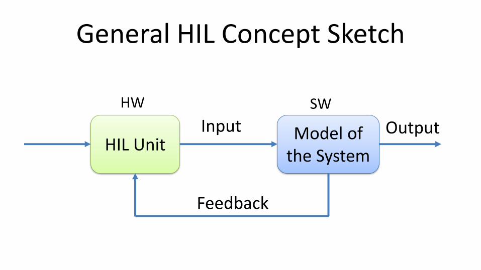
General HIL Concept Sketch
HIL UnitModel of
the System
Feedback
Input Output
HW SW

Lab Assignment Overview
1. Control and Simulation in LabVIEW using built-in PID Controller (Software only)– Create (or use prebuilt), Simulate and Control a Mathematical
model of an Air Heater (Software only)
2. HIL Simulation using PXG5 PID (HW + SW)– Control Mathematical model using PXG5– Test Auto-tuning with PXG5 PID
3. Test PXG5 on Real Process (Hardware only)
See next slides for details...

Learning Goals• Learn key concepts within Hardware in the loop (HIL)
simulations and testing• Learn practical skills and implementation of HIL applications• Learn practical skills in Modelling, Control and Simulation• Learn practical implementation of PID Control Systems• Learn more LabVIEW Programming• Learn about Hardware-Software Interactions• Learn Practical Skills and Implementations in general• Learn Software Installation in general, which can be
cumbersome with many pitfalls• Learn to use and create Software in general

HIL Simulation Lab - Step-by-step
1
2
3
Purpose: Create, Simulate, Control and Test the Mathematical Model
Purpose: Test your Hardware device before you apply it on your real system.Also useful for Training purposes.
Purpose: Apply your Hardware in the Production System
Step 1: Ordinary Software Simulation:
Step 2: HIL Simulation and Testing:
Step 3: Running the Real System:
Mathematical Model
Mathematical Model

Lab Overview Step 1: Simulation
Computer (with LabVIEW)
Control and Simulation in LabVIEW using built-in PID Controller and Mathematical Model of the Process (Software only)

Lab Overview Step 2: Use PXG5 with Model
I/O Module (USB-6008)
Model of Process (Air Heater)
PID Controller
Computer (with LabVIEW)
USB
Analog Out (Process Value)
Analog In (Control Signal)
Mathematical Model
Note!!
0-5V
1-5V
AO0
GND
AI0+
AI0-
PXG5 Industrial PID Controller
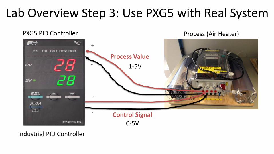
Lab Overview Step 3: Use PXG5 with Real System
Process (Air Heater)
Industrial PID Controller
1-5V
0-5V
Process Value
Control Signal
+
-
+
-
PXG5 PID Controller

Necessary Software
• LabVIEW
• LabVIEW Control & Simulation Module
• DAQmx Driver Software
Make sure to install the necessary Software before you go to the laboratory!
Software

Hardware
Your Personal Computer
Air HeaterUSB-6008
Hardware
Multimeter
We have limited numbers of PID Controllers, so 2 students may need to share a PID Controller
Fuji PXG5/PXR5 PID Controller

The Teacher dont have all the answers (very few actually )!! Sometimes you just need to “Google” in order to solve your problems, Collaborate with other Students, etc. Thats how you Learn!
The teacher have not done all the Tasks in detail, so he may not have all the answers! That's how it is in real life also!
Very often it works on one computer but not on another. You may have other versions of the software, you may have installed it in the wrong order, etc...In these cases Google is your best friend!

My System is not
Working??
You probably will find the answer on the Internet
Check your electric circuit, electrical cables, DAQ device, etc. Check if the wires from/to the DAQ device is correct. Are you using the same I/O Channel in your Software as the wiring suggest? etc.
Troubleshooting & Debugging
Another person in the world probably had a similar problem
Use the Debugging Tools in your Programming IDE. Visual Studio, LabVIEW, etc. have great Debugging Tools! Use them!!
Visual Studio Use available Resources such as User Guides, Datasheets, Text Books, Tutorials, Examples, Tips & Tricks, etc.
“Google It”!
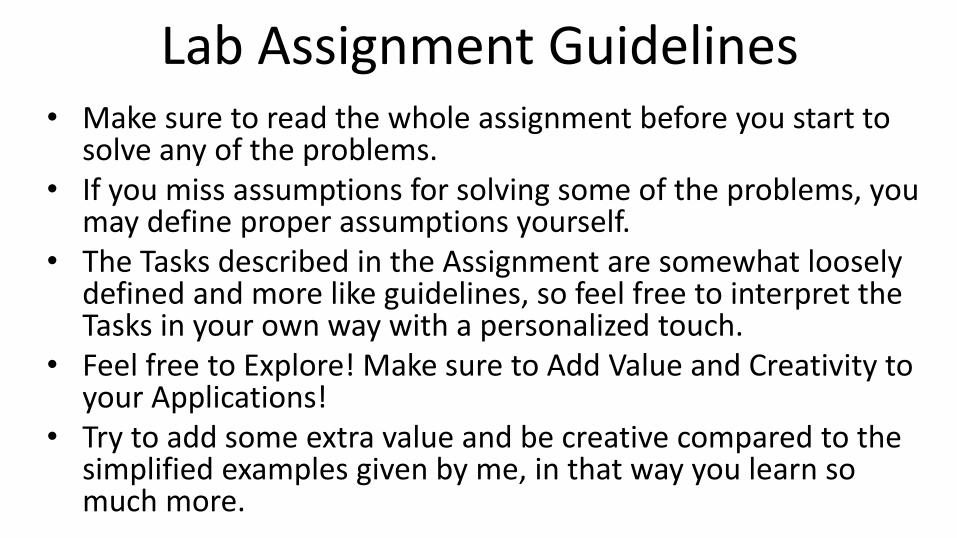
Lab Assignment Guidelines• Make sure to read the whole assignment before you start to
solve any of the problems.• If you miss assumptions for solving some of the problems, you
may define proper assumptions yourself.• The Tasks described in the Assignment are somewhat loosely
defined and more like guidelines, so feel free to interpret the Tasks in your own way with a personalized touch.
• Feel free to Explore! Make sure to Add Value and Creativity to your Applications!
• Try to add some extra value and be creative compared to the simplified examples given by me, in that way you learn so much more.
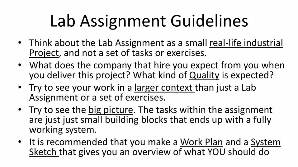
Lab Assignment Guidelines• Think about the Lab Assignment as a small real-life industrial
Project, and not a set of tasks or exercises. • What does the company that hire you expect from you when
you deliver this project? What kind of Quality is expected?• Try to see your work in a larger context than just a Lab
Assignment or a set of exercises. • Try to see the big picture. The tasks within the assignment
are just just small building blocks that ends up with a fully working system.
• It is recommended that you make a Work Plan and a System Sketch that gives you an overview of what YOU should do
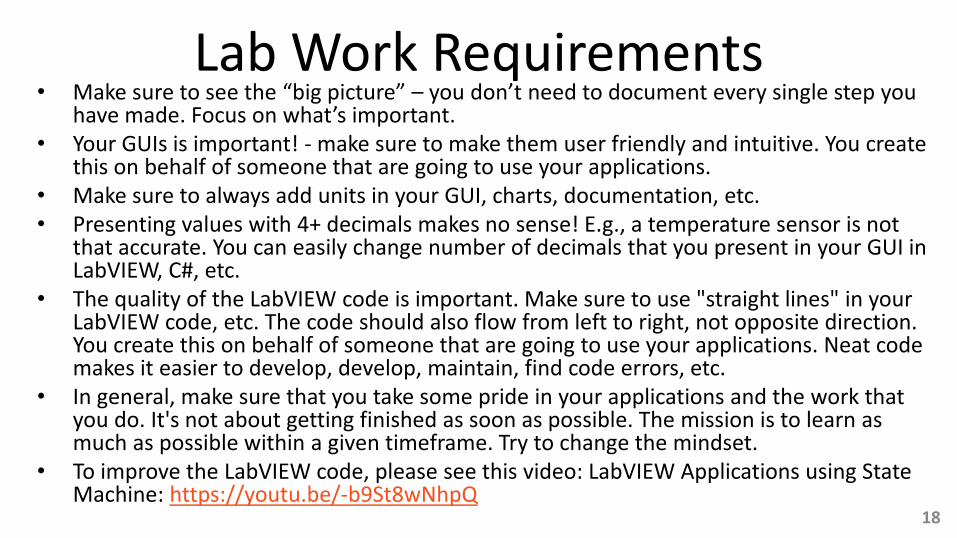
Lab Work Requirements• Make sure to see the “big picture” – you don’t need to document every single step you
have made. Focus on what’s important.• Your GUIs is important! - make sure to make them user friendly and intuitive. You create
this on behalf of someone that are going to use your applications.• Make sure to always add units in your GUI, charts, documentation, etc.• Presenting values with 4+ decimals makes no sense! E.g., a temperature sensor is not
that accurate. You can easily change number of decimals that you present in your GUI in LabVIEW, C#, etc.
• The quality of the LabVIEW code is important. Make sure to use "straight lines" in your LabVIEW code, etc. The code should also flow from left to right, not opposite direction. You create this on behalf of someone that are going to use your applications. Neat code makes it easier to develop, develop, maintain, find code errors, etc.
• In general, make sure that you take some pride in your applications and the work that you do. It's not about getting finished as soon as possible. The mission is to learn as much as possible within a given timeframe. Try to change the mindset.
• To improve the LabVIEW code, please see this video: LabVIEW Applications using State Machine: https://youtu.be/-b9St8wNhpQ
18

Introduction to HIL
Hans-Petter Halvorsen

What is HIL Simulation?
Hardware-In-the-Loop is a form of real-time simulation. Hardware-In-the-Loop differs from real-time simulation by the addition of a real component in the loop. This component may be an “Electronic Control Unit” (ECU).
Hardware-in-the-loop (HIL) simulation and testing is a technique that is used in the development and test of complex process systems. HIL simulation provides an effective platform by adding the complexity of the plant under control to the test platform.
The complexity of the plant under control is included in test and development by adding a mathematical representation of all related dynamic systems. These mathematical representations are referred to as the “plant simulation.”
The main purpose with the HIL Simulation is to Test the Hardware device on a Simulatorbefore we implement it on the real process.
[Wikipedia]

Example of PC-based Control System
I/O Module (USB-6008)
Computer (with LabVIEW)
Process (Air Heater)
Analog In (Process Value)
Analog Out (Control Signal)
PID Control and Monitoring
USB
0-5V
1-5V
(We shall not do like this in this Assignment!)
AO0
GND
AI0+
AI0-

Example of HIL Simulation
I/O Module (USB-6008)
Model of Process (Air Heater)
PID Control
Computer (with LabVIEW)
USB
Analog Out (Process Value)
Analog In (Control Signal)
Mathematical ModelNote!!
0-5V
1-5V
AO0
GND
AI0+
AI0-
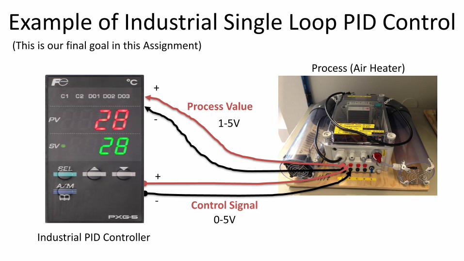
Example of Industrial Single Loop PID Control
Process (Air Heater)
Industrial PID Controller
1-5V
0-5V
Process Value
Control Signal
+
-
+
-
(This is our final goal in this Assignment)

Examples of Industrial Control Systems (ICS)
Distributed Control Systems (DCS)
DeltaVfrom Emerson
PLC (Programmable Logic Controller)
Siemens PLC
PC based Control System/SCADA System (Supervisory Control And Data Acquisition)
National Instruments
cRIO
Industrial Control Systems are computer controlled systems that monitor and control industrial processes that exist in the physical world
Controller I/O Modules
Industrial PIDController
I/O Module
Programmable Automation Controller (PAC)
LabVIEW

HIL Lab - Background• Typically, a simulator communicates with an “ECU” (“Electronic Control
Unit”) via ordinary I/O. Such a system - where the real controller is controlling a simulated process is denoted Hardware-in-the-loop (HIL) simulation.
• The main purpose with HIL is to test the hardware device on a simulator before we implement it on the real process.
• If the mathematical model used in the simulator is an accurate representation of the real process, you may even tune the controller parameters (e.g. the PID parameters) using the simulator.
• We will test the Fuji PGX5 PID controller on a model, and if everything is OK we will implement the controller on the real system.
Theory

Traditional Process Control using Software for Implementing the Control System
DAQAO
AI
u
yPID Process
yu
Software Hardware
PID Process DAQyu
AO
AIu
y
Hardware Software
HIL Simulation
Theory
Mathematical Model

HIL Simulation• Hardware-in-the-loop (HIL) simulation is a technique that is used in the
development and test of complex process systems
• The HIL simulation includes a mathematical model of the process and a hardware device/ECU you want to test, e.g. an industrial PID controller we will use in our example. The hardware device is normally an embedded system
• The main purpose with the HIL Simulation is to test the hardware device on a simulator before we implement it on the real process
• It is also very useful for training purposes, i.e., the process operator may learn how the system works and operate by using the hardware-in-the-loop simulation
• Another benefit of Hardware-In-the-Loop is that testing can be done without damaging equipment or endangering lives.
Theory

HIL Simulation using PXG5 PID Controller
PXG5PID Controller
Simulated Process
USB-6008
USB-6008 Scaling
Scaling?
𝑦 [20℃ − 50℃]𝑢 [0 − 5𝑉]𝑢 [0 − 5𝑉]
𝑦 [20℃ − 50℃][1 − 5𝑉]
𝑢
It depends on your settings
[1 − 5𝑉]
𝑓(𝑥) = 𝑎𝑥 + 𝑏
Analog Out (AO0)
Analog In (AI0)
Control Signal
Measurement

Simulated Control System
Hans-Petter Halvorsen
1Purpose: Create, Simulate, Control and Test the Mathematical Model
Step 1: Ordinary Software Simulation

Air HeaterSmall-scale Laboratory Process
Hans-Petter Halvorsen
1a
Air Heater

Air Heater System
Air In Air Out
Control Unit
Temperature Sensor on the outlet
𝑇𝑜𝑢𝑡Hea
ter
Fan
𝐾ℎ
𝑇𝑒𝑛𝑣 𝜃𝑑
𝜃𝑡
𝑢Control Signal to the Heater
𝑦 (𝑇𝑜𝑢𝑡)
Aim:Control the Temperature on the outlet (𝑇𝑜𝑢𝑡)
0 − 5𝑉
20 − 50℃
1 − 5𝑉

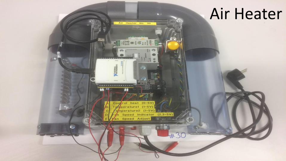
Air Heater
• Heater: The air is heated by an electrical heater. The supplied power is controlled by an external voltage signal in the range 0 - 5 V (min power, max power).
• Temperature sensors: A Pt100 temperature sensor. The range is 1 - 5V(Air Heater #1-17)/0-5V (Air Heater #18-32), and this voltage range corresponds with a linear relation to the temperature range 20 - 50oC (Air Heater #1-17) or 0 - 50oC (Air Heater #18-32).
Hardware
Example of Mathematical model for the Air Heater process:
ሶ𝑇𝑜𝑢𝑡 =1
𝜃𝑡−𝑇𝑜𝑢𝑡 + 𝐾ℎ𝑢 𝑡 − 𝜃𝑑 + 𝑇𝑒𝑛𝑣

Air Heater Mathematical Model
Use, e.g., these values in the Simulations:
Where:
Students: Implement and Simulate a Mathematical Model of the Air Heater using LabVIEW.
Hardware
ሶ𝑇𝑜𝑢𝑡 =1
𝜃𝑡−𝑇𝑜𝑢𝑡 + 𝐾ℎ𝑢 𝑡 − 𝜃𝑑 + 𝑇𝑒𝑛𝑣

Air Heater in LabVIEW
Example of Mathematical Model of Air Heater implemented in LabVIEW:
Heater: The air is heated by an electrical heater. The supplied power is controlled by an external voltage signal in the range 0 - 5 V (min power, max power).
Temperature sensors: Two Pt100 temperature elements are available. The range is 1 - 5 V, and this voltage range corresponds to the temperature range 20 - 50oC (with a linear relation).
Note! This model is implemented in a so-called “Simulation Subsystem” (which is recommended!!!)

Simulation SubsystemA Way to structure your code, similar to SubVIs
This is the recommended way to do it! – You can easily reuse your Subsystems in different VIs and your code becomes more structured!
Select File -> New ..., Then choose “Simulation Subsystem”. Create your Model within the Simulation Subsystem

Model Simulation Example (Note! No PID Control in this Example)
Note! This is just an Example! – You should create your own personal Application
Simulation SubSystem
Initialization
Clear the Charts, etc. using “Property Nodes”
Step Response
Manual Control
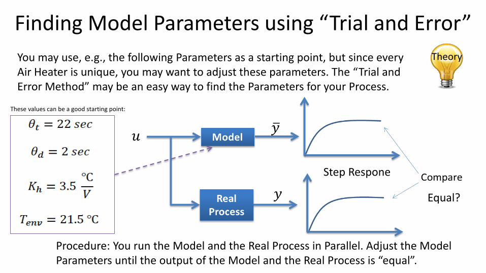
Finding Model Parameters using “Trial and Error”
You may use, e.g., the following Parameters as a starting point, but since every Air Heater is unique, you may want to adjust these parameters. The “Trial and Error Method” may be an easy way to find the Parameters for your Process.
Procedure: You run the Model and the Real Process in Parallel. Adjust the Model Parameters until the output of the Model and the Real Process is “equal”.
Equal?
Step Respone
Theory
These values can be a good starting point:
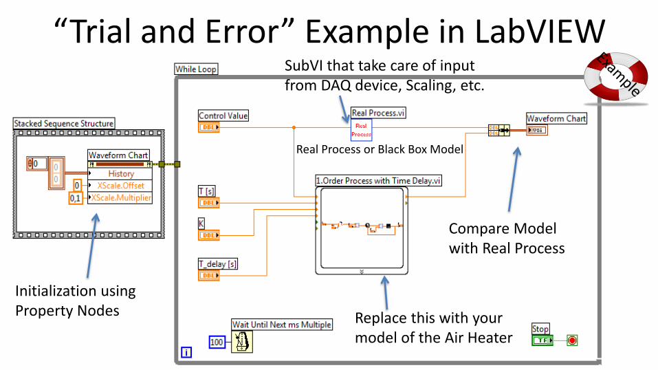
“Trial and Error” Example in LabVIEW
Compare Model with Real Process
SubVI that take care of input from DAQ device, Scaling, etc.
Replace this with your model of the Air Heater
Initialization using Property Nodes
Real Process or Black Box Model

“Air Heater Black Box Model”• The Real Air Heater is only available in the
Laboratory
• A “Real” Air Heater will we provided for download as a “black box”. Actually, it is a LabVIEW SubVI where the Block Diagram and the Process Parameters are hidden.
• Useful for Online Students and when you are working with the Assignment outside the Laboratory
• You can use it to find Model Parameters, etc. when you are not in the Laboratory
For Online Students

LabVIEW PID Controller
Hans-Petter Halvorsen
1b

PID Control of Model in LabVIEWThe Simulation Loop has some drawbacks/is more complicated to use than an ordinary While Loop. If we use Simulatation Subsystems, we can use them inside a While Loop instead! - which becomes very handy!
For real applications that involves more than just simulations (such as DAQ, File Logging, PID control of the real process, etc.), I recommend to use a While Loop instead of a Simulation Loop.
Students: Implement a Control System in LabVIEW where you use the built-in PID Controller and the Mathematical Model of the Air Heater
Feedback Node
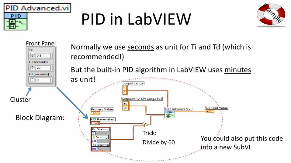
PID in LabVIEW
Normally we use seconds as unit for Ti and Td (which is recommended!)
But the built-in PID algorithm in LabVIEW uses minutesas unit!
Trick:
Divide by 60
Front Panel
Block Diagram:
You could also put this code into a new SubVI
Cluster
PID Parameters
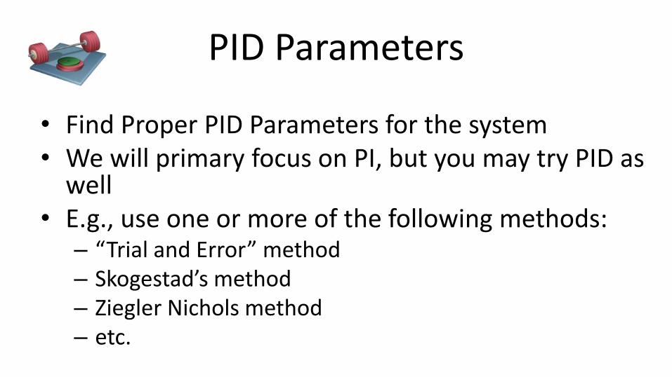
• Find Proper PID Parameters for the system• We will primary focus on PI, but you may try PID as
well• E.g., use one or more of the following methods:
– “Trial and Error” method– Skogestad’s method– Ziegler Nichols method– etc.

PID Tuning with Skogestad
We can set, e.g., Tc=10 sec. and c=1.5. You may use other values if these values give a poor result.
[Figures: F. Haugen, Advanced Dynamics and Control: TechTeach, 2010]

Congratulations! - You are finished with the Task

Lowpass Filter
Hans-Petter Halvorsen
1c

Lowpass Filter• You should consider using a Lowpass Filter in
order to reduce Noise– You can use a built-in Filter in LabVIEW – or you can create your own Lowpass Filter from scratch– or download a Lowpass Filter (LabVIEW SubVI) from
the Web site of this Lab Assignment– You should first Test it on the Mathematical model
before you apply it on the real system (next Task)See next slides for examples

Built-in Lowpass Filter to reduce Noise
Functions palette: Express -> Signal Analysis -> Simulate Signal
Functions palette: Express -> Signal Analysis -> Filter

Properties

Lowpass Filter created from Scratch
A golden rule is:
You may download this Lowpass Filter (LabVIEW SubVI) from the Web page of this Lab Assignment- or create your own from scratch

Discrete Lowpass Filter Example
We use the Euler Backward method:
Inverse Laplace the differential Equation:
This gives:
Lowpass Filter Transfer function: We define:
This gives:
This algorithm can be easily implemented in a Programming language such as LabVIEW
Filter output Noisy input signal

Testing the FilterIn this example we add noise to a Sine function. We then use the Measurement Filter to see if we can remove the noise afterwards.
As you can see this gives good results. The filter removes the noise from the signal.

Creating and Using SubVIs
SubVI that handlesthe I/O between LabVIEW and the Real Process
SubVI for Lowpass FilteringSubVI for Scaling
Convert from Dynamic Data
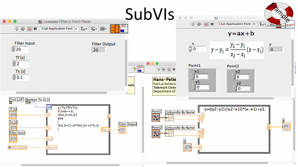
SubVIs

Congratulations! - You are finished with the Task
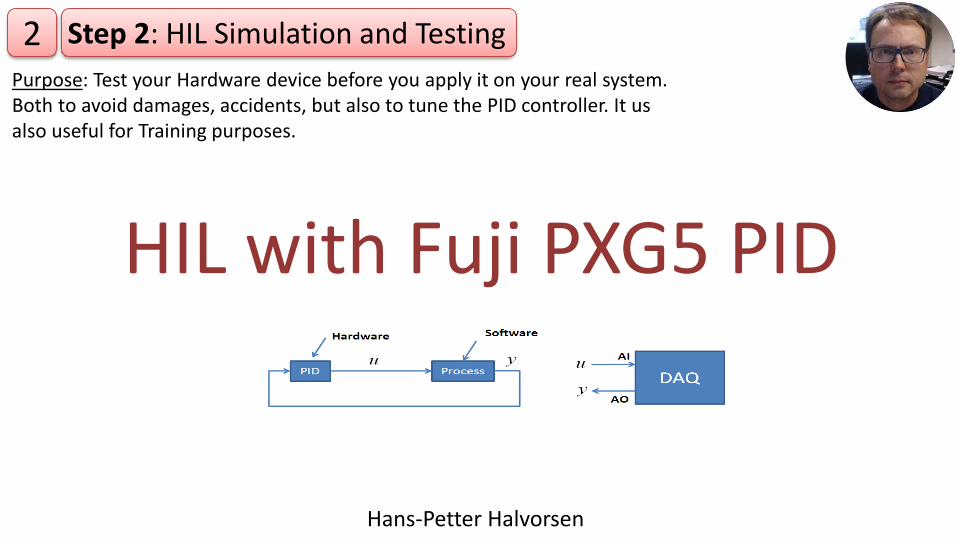
HIL with Fuji PXG5 PID
Step 2: HIL Simulation and Testing2Purpose: Test your Hardware device before you apply it on your real system. Both to avoid damages, accidents, but also to tune the PID controller. It us also useful for Training purposes.
Hans-Petter Halvorsen

Fuji PXG5 PID Controller

No Food and Drink allowed when you use the Fuji PXG5 hardware, because of risk of electric shock!Make sure to disconnect the power cable when wiring

HIL with Fuji PXG5/PXR5 PID
• It may be very useful to test a controller function with a simulated process before the controller is applied to the real (physical) process.
• If the mathematical model used in the simulator is an accurate representation of the real process, you may even tune the controller parameters (e.g. the PID parameters) using the simulator.
Theory

HIL Simulation Setup
I/O Module (USB-6008)
Model of Process (Air Heater)
PID Control
Computer (with LabVIEW)
USBAnalog Out (Process Value)
Analog In (Control Signal)
Mathematical ModelNote!!
0-5V
1-5V
AO0
GND
AI0+
AI0-

USB-6008 DAQAlways test your DAQ device before you use it in your application
Loopback Test:
1. Create the simple test program as shown below.
2. Wire the AO0 and AI0 cables together.
Should be equal
Numeric Control
Numeric Indicator
If you get the same value in the Analog Out and in the Analog In – you know your device is working properly
Students: Make sure your DAQ device works as expected

Fuji PXG5 PID Simulator❗️ The Fuji PXG5 PID is only available in the Laboratory. If you work at home you may want to use a “Fuji PXG5 PID Simulator”. You can create your own “Simulator” or download this Example from the Web Page of this Lab Work.
Change SV (Set Value) and PID Parameters
For Online Students

HIL Example with Fuji PXG5 PID Simulator
In this example you can easily switch between the Real Fuji PID Controller and a “Simulator”
For Online Students
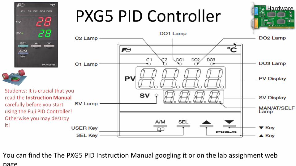
PXG5 PID Controller
You can find the The PXG5 PID Instruction Manual googling it or on the lab assignment web page
Hardware
Students: It is crucial that you read the Instruction Manual carefully before you start using the Fuji PID Controller!Otherwise you may destroy it!

66
PXG5 PID Controller Wiring Diagram
Hardware
Note! 230V – Be careful!!
We use a 250Ω resistor to convert the signal from 0-20mA to 0-5V
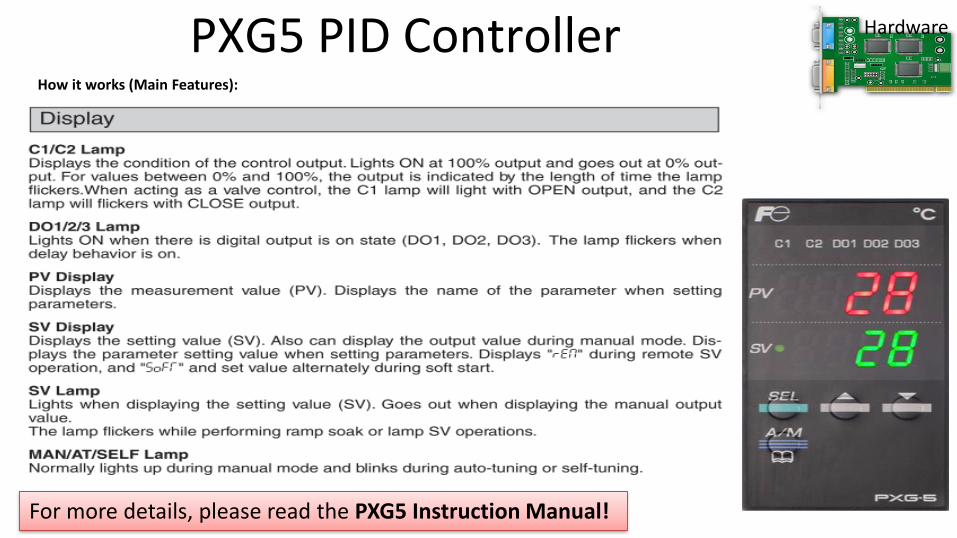
PXG5 PID ControllerHow it works (Main Features):
For more details, please read the PXG5 Instruction Manual!
Hardware

PXG5 - Configuration
Channel 1: Auto-tuning
Channel 2: PID Parameters
How-To Change Setpoint:
How-To Change Parameters:
Hardware
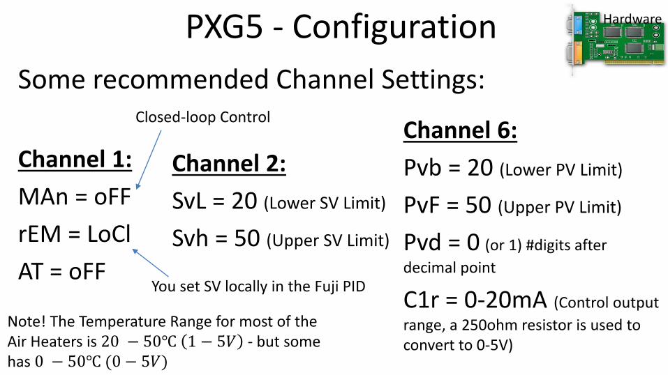
PXG5 - Configuration
Some recommended Channel Settings:
Channel 2:
SvL = 20 (Lower SV Limit)
Svh = 50 (Upper SV Limit)
Channel 6:
Pvb = 20 (Lower PV Limit)
PvF = 50 (Upper PV Limit)
Pvd = 0 (or 1) #digits after
decimal point
C1r = 0-20mA (Control output
range, a 250ohm resistor is used to convert to 0-5V)
Channel 1:
MAn = oFF
rEM = LoCl
AT = oFF
Hardware
Note! The Temperature Range for most of the Air Heaters is 20 − 50℃ 1 − 5𝑉 - but some has 0 − 50℃ (0 − 5𝑉)
Closed-loop Control
You set SV locally in the Fuji PID
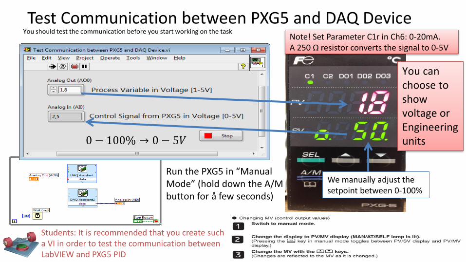
Test Communication between PXG5 and DAQ Device
We manually adjust the setpoint between 0-100%
Run the PXG5 in “Manual Mode” (hold down the A/M button for å few seconds)
0 − 100% → 0 − 5𝑉
You should test the communication before you start working on the task
Students: It is recommended that you create such a VI in order to test the communication between LabVIEW and PXG5 PID
You can choose to show voltage or Engineering units
Note! Set Parameter C1r in Ch6: 0-20mA. A 250 Ω resistor converts the signal to 0-5V

HIL Simulation in LabVIEW - Example
Students: Perform a HIL simulation using PXG5 and LabVIEW
SubVI:
You can use a Simulation Loop or a While Loop. A While loop is recommended.
Note! This is opposite of what you normally do
In Range and Coerce
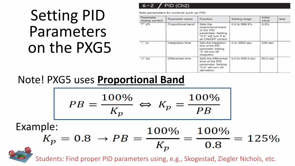
Note! PXG5 uses Proportional Band
Setting PID Parameterson the PXG5
Example:
Students: Find proper PID parameters using, e.g., Skogestad, Ziegler Nichols, etc.
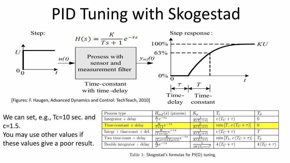
PID Tuning with Skogestad
We can set, e.g., Tc=10 sec. and c=1.5. You may use other values if these values give a poor result.
[Figures: F. Haugen, Advanced Dynamics and Control: TechTeach, 2010]

PXG5 – Auto-tuning
A lamp is blinking when the auto-tuning is running
Students: Test the Auto-tuning functionality built-into the PXG5 PID. Do you get the same results?

PXG5 – Auto-tuning
• Execute auto-tuning: What is the resulting P-, I- and D-values? What is the value of the controller gain (Kp) that corresponds to the P-value from the auto-tuning?
• Is the stability of the control system OK? (excite with a step in the Set-point/Reference Signal)
• Apply a step change in the reference: What is the steady-state control error?
• Reverse vs. Direct Action: happens to the stability of the control system if the controller mode is changed from Reverse action to Direct action? (In the controller manual, Direct action is denoted Normal mode.)
• Fine-tune the PID parameters if necessary.
Students:

Congratulations! - You are finished with the Task

Fuju PXG5 + Real Air Heater
Hans-Petter Halvorsen
3Purpose: Apply your Hardware in the Production Environment
Step 3: Running Hardware with the Real System

Fuju PXG5 + Real Air Heater
Students: Test the PXG5 PID Controller on the real Air Heater. Are you able to use the same PID settings you found using the Model? Test also the Auto-tuning functionality. Do you get the same parameters as using the model? Which PID parameters are best?
Industrial PID Controller
1-5V
0-5V
Process Value
Control Signal

When you are not in the Laboratory
For Online Students and when you are not on the Laboratory, you can use:
• “Fuji PXG5 PID Simulator”
• “Air Heater Black Box Model”
These can be downloaded from the website for this assignment
For Online Students

“Fuji PXG5 PID Simulator” + “Air Heater Black Box Model” Example
(You see the Block Diagram on the next slide)
For Online Students and when not on the Laboratory

“Fuji PXG5 PID Simulator” + “Air Heater Black Box Model” Example
Fuji PXG5 PID Simulator
Air Heater Black Box Model
For Online Students and when not on the Laboratory

Fuji PXG5 + Real Air Heater + PC for MonitoringIndustrial PID Controller
1-5V
Process Value
Trending/Monitoring the Process Value and Control Signal on the PC
USB
PC with LabVIEW
0-5V
Control Signal
y
With this setup you can Monitor (Plot and Log Data to File) the Process Value and Control Signal on your PC
1-5VProcess Value
Control Signal0-5V
u

Save Data to File (Datalogging)
Right-click-Properties
Recommended Settings

Datalogging Example

Measurement File – Data VisualizationOpen the File with Logged Data in e.g. Notepad:
Open the File with Logged Data in MS Excel and create a Chart (Measurement Value, Control Value)
85
Make sure to format number of Decimals

Congratulations! - You are finished with the Task

PID Parameters
Hans-Petter Halvorsen

Comparison of PID Parameters
Kp PB [%] Ti [sec] Td [sec] Tuning Method Comment
Built-in PID in LabVIEW
Fuji on Model
Fuji Autotuning on Model
Fuji on Real Process
Fuji Autotuning on Real Process
... others
Fill out a similar Table with the values you find. Discuss the Results.
Example:

Congratulations! - You are finished with the Task

Digital Twin
Hans-Petter Halvorsen
A brief Overview of a Digital Twin and how it is related to HIL Simulations
Digital Twin
• A digital twin is an exact digital replica of a product, process or service. This living model creates a thread between the physical and digital world
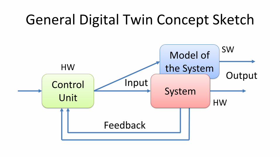
Model of the System
General Digital Twin Concept Sketch
Control Unit
System
Feedback
InputOutput
HW
SW
HW

Digital Twin
• Digital twins integrate internet of things, artificial intelligence, machine learning etc. to create living digital simulation models that update and change as their physical counterparts change.
• A digital twin continuously learns and updates itself from multiple sources (sensors, etc.) to represent its near real-time status

Digital Twin and HIL• The terms Digital Twin and Hardware in the Loop
Simulation are closely related.• National Instruments doesn’t use the term digital
twin, but its hardware-in-the-loop (HIL) testing technology platform provides similar functionality
• http://www.ni.com/en-no/innovations/automotive/hardware-in-the-loop.html• https://www.digitalengineering247.com/article/seeing-digital-twin-double/

Digital Twins in Automation Systems
• Preventive Maintenance
• Improved Control
• Model Based Control (MPC)
• State Estimation and Kalman Filter
• Can use the simulated environment to experiment with different controls strategies
• Model different scenarios to optimize the production
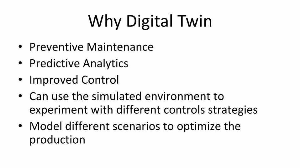
Why Digital Twin
• Preventive Maintenance
• Predictive Analytics
• Improved Control
• Can use the simulated environment to experiment with different controls strategies
• Model different scenarios to optimize the production

Fuji PXG5 + Real Air Heater + Digital Twin
Simulator
𝑢
𝑢
𝑦
𝑦
A Simulator running in parallel with the real system
Prediction and Analytics

Fuji PXG5 + Real Air Heater + Digital TwinIndustrial PID Controller
1-5V
Process Value
USB
0-5V
Control Signal
y1-5V
Process ValueControl Signal
0-5Vu
Model of Process (Air Heater)
Computer (with LabVIEW)

Congratulations! - You are finished with all the Tasks in the Assignment!

Hans-Petter Halvorsen
University of South-Eastern Norway
www.usn.no
E-mail: [email protected]
Web: https://www.halvorsen.blog