hierarchical control and full-range dynamic performance ... · the bidirectional buck/boost dc/dc...
TRANSCRIPT

0278-0046 (c) 2017 IEEE. Personal use is permitted, but republication/redistribution requires IEEE permission. See http://www.ieee.org/publications_standards/publications/rights/index.html for more information.
This article has been accepted for publication in a future issue of this journal, but has not been fully edited. Content may change prior to final publication. Citation information: DOI 10.1109/TIE.2017.2772174, IEEETransactions on Industrial Electronics
IEEE TRANSACTIONS ON INDUSTRIAL ELECTRONICS
Hierarchical Control and Full-range DynamicPerformance Optimization of Supercapacitor
Energy Storage System in Urban Railway
Feiqin Zhu, Student Member, IEEE, Zhongping Yang, Member, IEEE,Huan Xia, Member, IEEE, Fei Lin, Member, IEEE
Abstract—The installation of stationary supercapacitorenergy storage system in urban railway system effectivelyimproves the energy saving rate by means of recyclingthe train’s regenerative braking energy. In this paper, ahierarchical control strategy, which consists of an energymanagement layer and converter control layer, is proposed.In the energy management layer, the energy managementstate machine is introduced. In the converter control layer,based on the double closed-loop PI control strategy, amulti-objective optimization algorithm for the outer voltageloop is proposed, which optimizes the control parametersat each operating point, comprehensively considering un-dershoot suppression, rapidity and anti-disturbance per-formance of the system. The proposed control strategy isvalidated through simulation and laboratory experiment,and finally applied in the MW-level energy storage device(ESD) of Beijing Batong Line.
Index Terms—supercapacitor energy storage, urban rail,hierarchical control, dynamic performance, full-range opti-mization
I. INTRODUCTION
W ITH the rapid development of transportation system,the energy consumption and pollution become major
concern. Therefore, energy storage systems(ESSs) are widelyinvestigated to realize efficient electric drives in automobiles[1, 2] and rolling stocks [3, 4]. In metro system, the ESSs playthe role of braking energy recovery as well as network voltagestabilization [5]. Compared with other energy storage elementssuch as batteries and flywheels, supercapacitors are capable offast charging and discharging due to high power density, andhave great potential of energy recovery [6]. Therefore, energystorage systems based on supercapacitors have been installedin a number of metro lines around the world [7–9].
As the voltage of supercapacitor is coupled with the state ofcharge (SOC) [10, 11], the utilization ratio of supercapacitor
Manuscript received March 31, 2017; revised August 31, 2017; ac-cepted September 29, 2017. This work was supported in part by theNational Key Research and Development Program of China under Grant2017YFB1201105-05 (2017-2020) and the Fundamental ResearchFunds for the Central Universities of China under Grant 2017YJS182.
Feiqin Zhu, Zhongping Yang and Fei Lin are with the Schoolof electrical engineering, University of Beijing Jiaotong, Beijing,100044, China. (e-mail: [email protected]; [email protected];[email protected]).
Huan Xia is with the Beijing Institute of Space Launch Technology,Beijing, 100076, China. (e-mail: [email protected]).
energy will be very low if the supercapacitor is directlyconnected to the traction supply network. Therefore, a bidi-rectional DC/DC converter is used as the intermediate linkbetween the supercapacitor pack and traction network, whichtakes charge of the energy flow. The bidirectional buck/boostDC/DC converter, which has a small voltage stress and can beconnected in series-parallel to enhance the power capability, isused most widely for energy storage systems [12–14]. Asidefrom this, the converter topology has also been improved inpast studies, such as the three-level converter, which improvesthe efficiency of switching elements [15] and the cascadedconverter, which flexibly selects the voltage rating at both sidesof the converter [16].
The issue of ESS control refers to two aspects, i.e. powerflow management between the ESSs, trains and substations[17–19], and the energy-storage converter control. For energy-storage converter control, there are mainly two variables beingcontrolled, i.e. the supercapacitor current and the networkvoltage [20, 21]. The double closed-loop control strategy withproportional-integral (PI) regulators, in which the outer loopregulates voltage and the inner loop regulates current, is usedwidely for control of energy-storage converters, due to easyimplementation of its parameter settlings [22, 23]. In order torealize high-performance control, a polynomial control methodwas proposed in [24], on the basis of the converter model in thediscrete domain. W. Lhomme took the influence of the inductorimpedance on the system stability into consideration, andproposed a maximized control structure [25]. In [26], a slidingmode control method for the bidirectional DC/DC converterwas proposed. However, the inherent chattering problem ofsliding mode control has yet to be solved.
On account of the high power level of the energy storagesystem in urban railways [27], the linear control method basedon PI regulators is still the mainstream in practical applicationfor the purpose of ensuring reliability of the system. Thedistinctiveness for the converter in the application field ofurban rail systems is that the system operates intermittently,which requires rapid response to the shock of the vehicle’sregenerative braking current [28]. In addition, there is wide-range variation of the train current, supercapacitor voltageand network voltage, influencing the steady and dynamicperformance of the DC/DC converter, which is ignored bythe above papers. Therefore, designing the control strategyfor the DC/DC converter at different operating points will be

0278-0046 (c) 2017 IEEE. Personal use is permitted, but republication/redistribution requires IEEE permission. See http://www.ieee.org/publications_standards/publications/rights/index.html for more information.
This article has been accepted for publication in a future issue of this journal, but has not been fully edited. Content may change prior to final publication. Citation information: DOI 10.1109/TIE.2017.2772174, IEEETransactions on Industrial Electronics
IEEE TRANSACTIONS ON INDUSTRIAL ELECTRONICS
one aspect of research in the present paper.This paper is organized as follows: First, the working
principle and hierarchical control strategy of the stationarysupercapacitor energy storage system is presented. Then theholistic small-signal model is established, based on whichthe influence of steady-state variation on the system dynamicperformance is analyzed. Next, a full-range optimization al-gorithm for the outer loop control parameters is proposedto acquire the optimal performance at each operating point.Finally, the system model and control strategy are verified viasimulation, laboratory experiment and field test.
II. ESD IN URBAN RAIL AND ITS CONTROL
A. stationary supercapacitor energy storage systemAs the unidirectional diode rectifier cannot feed the DC
power of the urban rail system back to the AC grid, thestationary supercapacitor energy storage system (SCESS) isinstalled to recycle the regenerative energy of the braking train.The traction power supply system of the urban railway withSCESSs is shown in Fig. 1, where uss and iss respectivelydenote the voltage and current of the rectifier, uesd is the high-side voltage of the energy storage device (ESD), and usc is thesupercapacitor voltage. The traction substations convert the ACmedium-voltage power source (10 or 35 kV) to the urban railpower of DC 750 V (or 1500 V), and provide traction energyfor trains. In this paper, the ESD is supposed to be installedin the traction substation, in parallel with the rectifier, andthe supercapacitor is connected to the traction network with abidirectional DC/DC converter.
DC/DC
~
scu
ssi
+
-
+
-esdu
+
-ssu
10kV/35kV
750V/1500V
Fig. 1. Diagram of the traction power system with SCESS.
B. hierarchical control of SCESSIn order to logically control ESDs in urban rail systems, this
paper proposes a hierarchical control structure, as depicted inFig. 2. The control strategy is separated into two layers, i.e.the energy management layer and converter control layer, andlatter is embedded in the former layer. The energy manage-ment layer determines the operating states of supercapacitoraccording to usc, iss and uesd, sends corresponding voltageinstruction, which is uch in charge state, and uds in dischargestate to the converter control layer. The converter control layerdirectly controls the supercapacitor current and stabilizes thenetwork voltage at uch or uds.
In this paper, the energy management layer operates asa state machine, as seen in Fig. 3. Five states are defined,including the standby state, the charging state, the dischargingstate, the high-charge hold state and the low-charge hold state.
Energy
Storage
Device
Network
Voltage
Control
SC
Current
Control
Converter Control Layer
Energy Management Layer
Discharge
Charge
EMS
State
Machine
ssi
esdusciesdu
scu
chu
dsu
dsc,refi
Fig. 2. Structure of the hierarchical control strategy.
It executes a state transition when the transition conditionin the current state is satisfied. When the network voltageuesd is higher than the charge threshold uch,th, the systemoperates in charge state, the state machine will send thevoltage reference uch (≥ uch,th) to the converter control layer.When the rectifier current iss is larger than zero, whichmeans the network voltage is pulled down by the tractiontrains, the system transfers to the discharge state. In high-charge hold or low-charge hold state, charge and dischargebehavior are forbidden. For the low-charge hold state, onlywhen the condition uesd > uch is satisfied will the ESDreturns the charge state, and for the high-charge hold state,the ESD transfers to the discharge state when iss > 0. Theadvantage of the state machine is that it switches the systemto the expected state steadily, sends relevant instructions to theconverter control layer, thus satisfying the power requirementof the traction network, protecting supercapacitor from fullcharge/discharge, and preventing state oscillation. Besides,the discharge behavior is triggered by the substation current,which weakens the influence of no-load voltage fluctuation.
Charge command=0;Discharge command=0;
Charge command=0;Discharge command=1;
sc sc,lowu u
sc sc,highu u
Precharge
ds ssu u ss 0i
sc sc,lowu u
ds ssu u
ss 0i
Start
esd chu u
esd chu u
esd chu u
Charge command=0;Discharge command=0;
Charge command=1;Discharge command=0;
Charge command=0;Discharge command=0;
Discharging state
Standby state
Low-charge hold state
High-charge hold state
Charging state
Fig. 3. The state machine for energy management layer.
In the converter control layer, the voltage-current doubleclosed loop control structure is adopted, as seen in Fig. 4.The voltage reference uesd,ref is obtained from the energymanagement layer, which equals uch in charge state, andequals uds in discharge state, as seen in (1). Gvc and Gic
represent the voltage regulator of the outer loop and currentregulator of the inner loop, respectively. us,up and us,down arethe upper and lower limits of the reference current. The outerloop regulates the network voltage uesd, generating referencecurrent iL,ref for the inner loop, and the inner loop controls

0278-0046 (c) 2017 IEEE. Personal use is permitted, but republication/redistribution requires IEEE permission. See http://www.ieee.org/publications_standards/publications/rights/index.html for more information.
This article has been accepted for publication in a future issue of this journal, but has not been fully edited. Content may change prior to final publication. Citation information: DOI 10.1109/TIE.2017.2772174, IEEETransactions on Industrial Electronics
IEEE TRANSACTIONS ON INDUSTRIAL ELECTRONICS
the supercapacitor current by adjusting duty cycle of theIGBT driving pulse. Under the condition of train braking, uesd
rises, negative voltage error is obtained by subtracting uesd,reffrom uesd. Thereafter, the voltage regulator generates negativecurrent reference iL,ref , and the current controller regulatesthe supercapacitor current to the reference value. Therefore,the surplus braking energy is charged to the supercapacitor,and the network voltage ceases rising. Analogously, duringtrain traction, the voltage regulator generates positive currentinstruction, and the supercapacitor releases energy to stabilizethe network voltage at uds.
uesd,ref =
uch,Charge command = 1uds,Discharge command = 1 (1)
+- -
PWM
PWM
DC/DC
esd,refu
esdu
vcGs,downu
s,upu L,refi+
Li
icG1
0
-
2d1d
2SM
1SM
1 +
Fig. 4. The converter control layer(double-closed loop control).
From the perspective of control objective, the goal of theenergy management layer is to optimize the power flow ofthe traction power network by adjusting the charge/dischargevoltage references, thus improving the energy efficiency of thepower supply system. And the goal of the converter controllayer is to track the voltage instructions of the energy manage-ment layer rapidly and stably. The dynamic performance of theconverter control layer is essential to the voltage stabilizationand braking energy recovery effect, which is the focus of thefollowing paper.
III. DYNAMIC PERFORMANCE OPTIMIZATION FORCONVERTER IN SCESS
A. Holistic model of SCESS
In this paper, a holistic model, which includes the superca-pacitor, DC/DC converter, the substation and equivalent loadof trains, is established. The train is modeled as a currentsource it, which satisfies it = pt/ut. So the equivalent loadto one branch of the ESD is ir = it/Nbch. The substation ismodeled as a branch that consists of a diode, an equivalentresistance and a voltage source. And the supercapacitor ismodeled as a voltage source in series with the equivalentinternal resistance, as the change of the supercapacitor voltageis very slow, influencing the steady state of the DC/DCconverter instead of the dynamic behavior.
The topology of the holistic energy storage system isdepicted in Fig. 5. uss0 and Rss are the no-load voltage andequivalent resistance of the substation. Cf and R1 are thecapacitance and equivalent resistance of the filter capacitor,and L and R2 are the inductance and equivalent resistanceof the filter inductor. The supercapacitor is connected withthe DC/DC converter at the low-voltage side, where R3 is
1T
Li
ri1R
+
-
+
-
2R
3R
ou
L
2T+
-
Super-
capacitor
Buck/Boost
ConverterTrain
cfufC +
-
Substation
0ssu
ssR
ssi
esdu esdi
Fig. 5. Circuit structure of energy storage device.
the equivalent internal resistance of the supercapacitor and uo
represents the voltage of its capacitive part.The energy storage system is modeled with the state-space
averaging method. In this paper, the converter models undercharge and discharge conditions are unified, as the converter isregarded as a boost converter with current direction reversedin charge condition. For convenience, R2 +R3 is denoted byR23, and the duty cycle of the driving pulse is denoted by d.The averaged state equation is formulated as (2).
[ diLdt
ducfdt
]=
[−R23+(1−d)R1
L − 1−dL
1−dCf
0
] [iLucf
]+
[R1(1−d)
L1L
− 1Cf
0
] [iesduo
] (2)
[uesd] =[(1− d)R1 1
] [ iLucf
]+[−R1 0
] [ iesduo
](3)
In the steady state, the state variables satisfy diL/dt = 0,ducf/dt = 0, and the steady-state solution is obtained from(2) and (3):
[ILUcf
]=
[1
1−D 0−R1D(1−D)−R23
(1−D)21
1−D
] [IesdUo
](4)
[Uesd] =[
−R1D(1−D)−R23
D21
1−D
] [IesdUo
](5)
Exerting disturbance on (4) and (5), and ignoring thequadratic terms yields the linearized dynamic equation. Thenwe apply the Laplace transformation, and solve the statevariables and output variable, which are expressed as follows:
iL (s) =1
Ls+R23 + (1−D)R1·(
− (1−D) ucf +R1 (1−D) iesd
+uo + (Ucf +R1IL −R1Iesd) d
) (6)
ucf (s) =(1−D) iL (s)− ILd (s)− iesd (s)
Cs(7)
uesd (s) = (1 +R1Cs) ucf (s) (8)
Generally, the supercapacitor discharges when the networkvoltage uesd is lower than the no-load voltage of substation,

0278-0046 (c) 2017 IEEE. Personal use is permitted, but republication/redistribution requires IEEE permission. See http://www.ieee.org/publications_standards/publications/rights/index.html for more information.
This article has been accepted for publication in a future issue of this journal, but has not been fully edited. Content may change prior to final publication. Citation information: DOI 10.1109/TIE.2017.2772174, IEEETransactions on Industrial Electronics
IEEE TRANSACTIONS ON INDUSTRIAL ELECTRONICS
and charges vice versa. So in charge condition, the diode ofthe substation branch cuts off. The ESD output current iesd isexpressed by (9).
iesd =
ir, chargingir − (uss0 − uesd) /Rss,discharging
(9)
The system equivalent block diagram is deducedfrom (6), (7), (8) and (9), as shown in Fig. 6. The transferfunction from the supercapacitor current to the networkvoltage Gvi is obtained, which is given by (10) and (11).Considering that the inner current loop is much faster thanthe outer voltage loop, the influence of ucf and uesd on theinner loop is neglected in discharge condition.
23 1
1
1Ls R D R 1 D
1 D
1 1R D
---d
ss
1
Rssi
-
Influence of substationin discharge condition
f
1
C s
cfu
1 f1 R C scf 1 L 1 esdU R I R I
1 1R D
ou
LI
esdu
ri
Li
Fig. 6. The equivalent block diagram of the energy storage system.
Gvi (s) |charging =(CR1s+ 1)
(Ucf −R1 + ILR1)Cfs+ Iesd·
[−ILLs+ (1−D)Ucf − ILR23 − (1−D)R1]
(10)
Gvi |discharging ≈Rss (R1Cfs+ 1)
[(Rss +R1)Cfs+ 1] · (Ucf +DR1IL)·
[−ILLs+ (1−D)Ucf − ILR23 − (1−D) IesdR1](11)
B. Influence of steady-state on dynamic performanceIt can be seen from (10) and (11) that Gvi(s) has two
open-loop zeros and one open-loop pole, as shown in (12).The zero z1 arises from the equivalent resistor of the filtercapacitor, which has an effect in high frequency, thus can beneglected. The zero z2 is relevant the inductor current IL andsupercapacitor voltage Uo.The pole p is constant in dischargecondition, but influenced by the ESD output current Iesd andthe filter capacitor voltage Ucf in charge condition.
z1 = −1/ (R1Cf) , z2 = Uo/ (ILL) ,
p ≈−Iesd/ (UcfCf) , charging−1/ (Rss +R1)Cf ,discharging
(12)
Taking the MW-level ESD (see Section. V-B) as an example,the influence of steady-state variation on system performanceis analyzed. The ESD has eight branches in parallel, and theparameters of one branch are used for simulation, which arelisted in Table. I. As there is coupling relationship betweensteady-variables Iesd, IL, and Uo, Uesd and D (see (4) and(5)), the following discussion mainly concerns the variationof Iesd and D.
The bode diagram of Gvi and the distribution graphs of zeroz2 and pole p under different Iesd in discharge condition are
TABLE IPARAMETERS OF THE MW-LEVEL ENERGY STORAGE SYSTEM.
Parameters Symbols Vaules Unit
filter capacitance Cf 12 mFinductance L 1.5 mHresistance R1 1 mΩ
resistance R23 18.5 mΩ
switching frequency fsw 3000 Hz
plotted, as seen in Fig. 7 (a)-(c). It’s seen that in dischargecondition, zero z2 locates in the right half plane and the polep is in the left half plane, which means that the system isnon-minimum phase. Besides, when Iesd increases from 30Ato 150A, the value of z2 reduces from 7390 to 1460. Asthe zero affects the corner frequencies of the system, thelog-magnitude curve and the phase-angle curve also moveobviously. In particular, the phase-angle lags more in mediumfrequency range with the increase of Iesd and decrease of thepositive zero. In charge condition, the influence of Iesd on thesystem characters is shown in Fig. 8 (a)-(c). In contrast withthat in discharge condition, the zero z2 becomes negative butthe pole p is positive, which means the system is open-loopunstable. As a matter of fact, p is canceled by a positive zeroof Gid, and the system has a hidden instability. The systemfrequency response is also influenced by Iesd significantly.
-60
-40
-20
0
20
Mag
nitu
de (
dB)
100 102 104 106180
270
360
Pha
se (
deg)
Iesd=30AIesd=50AIesd=100AIesd=150A
(a).
Frequency (Hz)
2000 4000 6000 8000-1
0
1(b).
Re (seconds -1)
Im (
seco
nds
-1)
-800 -600 -400 -200-1
0
1(c).
Re (seconds -1)
Im (
seco
nds
-1)
Fig. 7. Influence of Iesd on Gvi in discharging condition.
-60
-40
-20
0
20
40
Mag
nitu
de (
dB)
100 105-180
-90
0
90
Pha
se (
deg)
Iesd=-30AIesd=-60AIesd=-90AIesd=-110A
(a).
Frequency (Hz)
-4000 -3000 -2000 -1000 0-1
0
1(b).
Im (
seco
nds
-1)
0 5 10 15-1
0
1
Re (seconds -1)(c).
Re (seconds -1)
Im (
seco
nds
-1)
Fig. 8. Influence of Iesd on Gvi in charging condition.
The influence of D on the system characters is shown inFig. 9 and Fig. 10. It’s observed that when D increases,the zero z2 is moving closer to the origin while p remainsunchanged. Therefore, the phase-angle in the middle frequencyrange lags more in discharge condition and is getting moreahead in charge condition with the increase of D.
0278-0046 (c) 2017 IEEE. Personal use is permitted, but republication/redistribution requires IEEE permission. See http://www.ieee.org/publications_standards/publications/rights/index.html for more information.
This article has been accepted for publication in a future issue of this journal, but has not been fully edited. Content may change prior to final publication. Citation information: DOI 10.1109/TIE.2017.2772174, IEEETransactions on Industrial Electronics
IEEE TRANSACTIONS ON INDUSTRIAL ELECTRONICS
-40
-30
-20
-10
0
10
Mag
nitu
de (
dB)
100 102 104 106180
270
360
Pha
se (
deg)
D=0.25D=0.4D=0.5D=0.6
(a).
Frequency (Hz)
1000 2000 3000 4000-1
0
1(b).
Re (seconds -1)
Im (
seco
nds
-1)
-800 -600 -400 -200-1
0
1(c).
Re (seconds -1)
Im (
seco
nds
-1)
Fig. 9. Influence of D on Gvi in discharging condition.
-40
-20
0
20
Mag
nitu
de (
dB)
100 105-180
-90
0
90
Pha
se (
deg)
D=0.25D=0.4D=0.5D=0.6
(a).
Frequency (Hz)
-4000 -3000 -2000 -1000 0-1
0
1(b).
Re (seconds -1)
Im (
seco
nds
-1)
0 5 10 15 20-1
0
1(c).
Re (seconds -1)
Im (
seco
nds
-1)
Fig. 10. Influence of D on Gvi in charging condition.
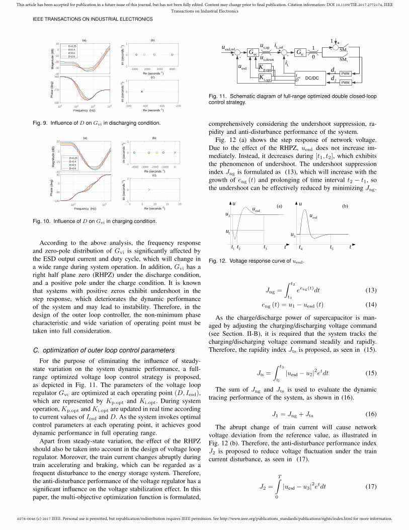
According to the above analysis, the frequency responseand zero-pole distribution of Gvi is significantly affected bythe ESD output current and duty cycle, which will change ina wide range during system operation. In addition, Gvi has aright half plane zero (RHPZ) under the discharge condition,and a positive pole under the charge condition. It is knownthat systems with positive zeros exhibit undershoot in thestep response, which deteriorates the dynamic performanceof the system and may lead to instability. Therefore, in thedesign of the outer loop controller, the non-minimum phasecharacteristic and wide variation of operating point must betaken into full consideration.
C. optimization of outer loop control parameters
For the purpose of eliminating the influence of steady-state variation on the system dynamic performance, a full-range optimized voltage loop control strategy is proposed,as depicted in Fig. 11. The parameters of the voltage loopregulator Gvc are optimized at each operating point (D, Iesd),which are represented by Kp.opt and Ki.opt. During systemoperation, Kp.opt and Ki.opt are updated in real time accordingto current values of Iesd and D. As the system invokes optimalcontrol parameters at each operating point, it achieves gooddynamic performance in full operating range.
Apart from steady-state variation, the effect of the RHPZshould also be taken into account in the design of voltage loopregulator. Moreover, the train current changes abruptly duringtrain accelerating and braking, which can be regarded as afrequent disturbance to the energy storage system. Therefore,the anti-disturbance performance of the voltage regulator has asignificant influence on the voltage stabilization effect. In thispaper, the multi-objective optimization function is formulated,
DesdI
+- -
PWM
PWM
DC/DC
esd,refu
esdu
vcGs,downu
s,upu L,refi+
Li
icG1
0
-
2d1d
1SM
p.optK
i.optK
1SM
1 +
Fig. 11. Schematic diagram of full-range optimized double closed-loopcontrol strategy.
comprehensively considering the undershoot suppression, ra-pidity and anti-disturbance performance of the system.
Fig. 12 (a) shows the step response of network voltage.Due to the effect of the RHPZ, uesd does not increase im-mediately. Instead, it decreases during [t1, t2], which exhibitsthe phenomenon of undershoot. The undershoot suppressionindex Jng is formulated as (13), which will increase with thegrowth of eng (t) and prolonging of time interval t2 − t1, sothe undershoot can be effectively reduced by minimizing Jng.
t3t
1u
2uesdu
t
3u
esdu
u u
1t 2t
(a) (b)
4t 5t
Fig. 12. Voltage response curve of uesd.
Jng =
∫ t2
t1
eeng(t)dt (13)
eng (t) = u1 − uesd (t) (14)
As the charge/discharge power of supercapacitor is man-aged by adjusting the charging/discharging voltage command(see Section. II-B), it is required that the system tracks thecharging/discharging voltage command steadily and rapidly.Therefore, the rapidity index Jts is proposed, as seen in (15).
Jts =
∫ t3
t2|uesd − u2|2etdt (15)
The sum of Jng and Jts is used to evaluate the dynamictracing performance of the system, as shown in (16).
J1 = Jng + Jts (16)
The abrupt change of train current will cause networkvoltage deviation from the reference value, as illustrated inFig. 12 (b). Therefore, the anti-disturbance performance indexJ2 is proposed to reduce voltage fluctuation under the traincurrent disturbance, as seen in (17).
J2 =
T∫0
|uesd − u3|2etdt (17)

0278-0046 (c) 2017 IEEE. Personal use is permitted, but republication/redistribution requires IEEE permission. See http://www.ieee.org/publications_standards/publications/rights/index.html for more information.
This article has been accepted for publication in a future issue of this journal, but has not been fully edited. Content may change prior to final publication. Citation information: DOI 10.1109/TIE.2017.2772174, IEEETransactions on Industrial Electronics
IEEE TRANSACTIONS ON INDUSTRIAL ELECTRONICS
The overall optimization objective J is the weighted sumof sub-objective J1 and J2.
J = ωJ1 + (1− ω)J2 (18)
Where ω is the weighting factor of the objective functionJ1. Properly allocating the weights of J1 and J2 achievesfavorable trade-off between the dynamic performance and anti-disturbance ability of the system. The cutoff frequency ωcvof the voltage loop is restricted within 1/10 of the cutofffrequency of the current loop to prevent the influence of thecurrent loop on the voltage loop.
The flow chart of the full-range parameter optimizationalgorithm is shown in Fig. 13. The control parameters Kp andKi are optimized at each operating point (D, Iesd) with thegenetic algorithm. Each individual represents a design point(Kp,Ki). The performance index J is calculated by substi-tuting (D, Iesd) and (Kp,Ki) into the transfer functions, andsolving the responses to the step reference and disturbance.The genetic algorithm executes the genetic operators andgenerates the next population with improved fitness. The al-gorithm terminates when the control parameters of all steady-state points are optimized. Finally, in order to implementreal-time calculation of the optimal control parameters whenthe operating condition of the ESD changes, the optimizationresults are fitted with the least square method, and written intothe DSP program as a function of D and Iesd.
Select point
Generic
operators
Reproduction
Crossover
Mutation
r( , )D I
v1( )T s v2 ( )T s
ngJtsJ 2J
Stopping criterion satisfied ?
Initialize p i( , )K K
Population
Update population
All points Selected ?
Yes
No
+ +
+ +
1
1J
p i( , )K K
No J
Start
EndYes
Fig. 13. Optimization algorithm for control parameters of outer voltageregulating loop.
IV. CASE STUDY AND SIMULATION ANALYSIS
A. Optimization results
With the optimization algorithm proposed in last section,the control parameters Kp and Kp of the voltage outer loopare optimized when the weighting factor ω is 1, 0.5 and 0.1.The system parameters are listed in Table I . The optimizationresults under different ω are compared in Fig. 14. Fig. 14 (a)and (b) shows the responses of uesd to step voltage reference
and step disturbance of train current in discharge condition.The undershoot phenomenon becomes more serious when ωis small. And in the charge condition, the influence of ωon the voltage responses is shown in Fig. 14 (c), (d). Withthe increase of ω, the response to step disturbance of traincurrent deteriorates: the voltage deviation increases and therecovery time is longer. Particularly when ω=1, the recoverytime is 5 times longer than that when ω=0.1. Therefore, theweighting factor ω should be selected reasonably accordingto the system state and control target. The system reachesgood compromise between the dynamic performance and anti-disturbance ability under the charge and discharge conditionswhen the control parameters are optimized under ω=0.5. Theoptimization results under ω=0.5 are shown in Fig. 15 .
0 0.05 0.1 0.15 0.2 0.25 0.3
Time(s)
848
850
852
854
856
858
860
u esd
(V)
(c).
0 0.2 0.4 0.6 0.8 1
Time(s)
860
862
864
866
868
870
u esd
(V)
(d).
0.04 0.05 0.06 0.07 0.08 0.09 0.1
Time(s)
858.5
859
859.5
860
860.5
861
861.5
862
862.5
u esd
(V)
(a).
0.04 0.06 0.08 0.1 0.12 0.14
Time(s)
858
858.5
859
859.5
860
860.5
u esd
(V)
(b).
!=1!=0.5!=0.1
!=1!=0.5!=0.1
Fig. 14. Influence of ω on the voltage loop performance in discharg-ing/charging conditions.
10
2
0.8-50
3
(a). Kpch, !=0.5
Iesd
0.6
D
4
-100 0.4-150 0.2
500
100
0.8-50
150
(b). Kich, !=0.5
Iesd
0.6
D
200
-100 0.4-150 0.2
0150
5
0.8100
10
(c). Kpds, !=0.5
Iesd
0.6
D
15
50 0.40 0.2
1000150
2000
0.8100
(d). Kids, !=0.5
Iesd
0.6
D
3000
50 0.40 0.2
Fig. 15. The optimization results of voltage controller parameters.
B. Simulation resultBased on the optimization results under ω=0.5, the perfor-
mance of the controller Gvc is analyzed. Fig. 16 (a) and (b) arestep responses to the voltage reference at different operatingpoint in discharge condition. The reference of uesd rises from860V to 862V at 0.5s. It’s observed that the undershoot is

0278-0046 (c) 2017 IEEE. Personal use is permitted, but republication/redistribution requires IEEE permission. See http://www.ieee.org/publications_standards/publications/rights/index.html for more information.
This article has been accepted for publication in a future issue of this journal, but has not been fully edited. Content may change prior to final publication. Citation information: DOI 10.1109/TIE.2017.2772174, IEEETransactions on Industrial Electronics
IEEE TRANSACTIONS ON INDUSTRIAL ELECTRONICS
effectively suppressed, which is less than 2V, and the transientprocess is very rapid, which is within 50ms when D variesfrom 0.25 to 0.6 and Iesd varies from 8A to 150A. Figs. 16 (c)and (d) show the responses curves to step disturbance of traincurrent at different operating points. ir steps at 0.5s with a stepamplitude of 15A. The maximum voltage drop of uesd is 2V,which occurs when D=0.6. The voltage fluctuation is rathersmall in discharge condition, as the substation also suppliespower during abrupt change of train current. And the recoverytime is within 50ms in the full variation range of D and Iesd.
0.5 0.6 0.7Time (s)
855
856
857
858
859
860
861
862
u esd
(V)
(c).
D=0.6D=0.5D=0.4D=0.25
0.5 0.6 0.7Time (s)
855
856
857
858
859
860
861
862
u esd
(V)
(d).
Iesd=150AIesd=103AIesd=55AIesd=8A
0.5 0.6 0.7Time (s)
857
858
859
860
861
862
863
864
u esd
(V)
(a).
D=0.6D=0.5D=0.4D=0.25
0.5 0.6 0.7Time (s)
857
858
859
860
861
862
863
864
u esd
(V)
(b).
Iesd=150AIesd=103AIesd=55AIesd=8A
Fig. 16. Step response of the corrected outerloop in dischargingCondition.
The step responses of uesd in charge condition are shownin Figs. 17 (a), (b). The voltage reference reduces from 860Vto 850V at 0.5s. As Gvi has no positive zero in charge con-dition, the step responses don’t exhibit undershoot. Besides,the response curves at different operating points have goodconsistency, and the settling time is within 100ms. Figs. 17 (c)and (d) are responses of uesd to step disturbance of traincurrent ir. ir steps at 0.5s with an amplitude of 15A. It’sobserved that the maximum voltage fluctuation is 7.3V andthe recovery time is within 150ms. The system has goodperformance of anti-disturbance.
Therefore, in comparison with the traditional control strat-egy, the multi-objective optimization strategy proposed in thispaper adjusts the control parameters according to the systemoperating point in real-time, preventing performance deteri-oration when the duty cycle D and ESD current Iesd vary,and achieving satisfactory performance in the full operatingrange. And the three optimization objectives, including therapidity index, the undershoot suppression index and the anti-disturbance index are optimized simultaneously, so the energystorage system tracks the voltage reference stably and rapidly,weakening the influence of train current disturbance and theRHPZ in discharging condition.
0.45 0.5 0.55 0.6 0.65 0.7 0.75Time (s)
846
848
850
852
854
856
858
860
862
u esd
(V)
(a).
D=0.6D=0.5D=0.4D=0.25
0.45 0.5 0.55 0.6 0.65 0.7 0.75Time (s)
846
848
850
852
854
856
858
860
862
u esd
(V)
(b).
Iesd=-150AIesd=-103AIesd=-55AIesd=-8A
0.45 0.5 0.55 0.6 0.65 0.7 0.75Time (s)
858
860
862
864
866
868
u esd
(V)
(c).
D=0.6D=0.5D=0.4D=0.25
0.45 0.5 0.55 0.6 0.65 0.7 0.75Time (s)
858
860
862
864
866
868
u esd
(V)
(d).
Iesd=-150AIesd=-103AIesd=-55AIesd=-8A
Fig. 17. Step response of the corrected outerloop in charging Condition.
V. EXPERIMENTAL VERIFICATION
A. Laboratory experimentA 200 kW supercapacitor energy storage device and an
experimental platform which emulates the operation of urbanrail systems are developed in the laboratory, as shown inFigs. 18. The parameters of the prototype are listed in Table. II.The supercapacitor pack is connected with four Maxwell 125V / 63 F modules in series and two in parallel, with a totalstorage energy of 1.09 kWh. In the emulation platform, thetransformer and rectifier convert the AC 380 V power sourceto DC 750 V, emulating the power supply system in urbanrailway, and the motors with traction converters emulate thetrain operation.
TABLE IIPARAMETERS OF THE 200KW PROTOTYPE.
Parameters Values Unit
filter capacitance 5 mFchopper inductance 2.5 mH
network voltage 700-1000 Voutput volage 100-500 Voutput current 400 A
total capacitance of supercapacitor 31.5 F
Traction converters
Load motor
Traction motor
(a)
Inverter
Braking
chopper
Bidirectional
DC/DC
Diode
rectifier
Train emulation system
Three-phase AC 380V
Supercapacitor
modules
DC bus(750V)
DC-
DC+
Braking
resistor
Traction motor
Load motor
Dynamometer
converter
(b)
Fig. 18. Diagram of the experimental platform.
Firstly, the dynamic performance of the proposed optimiza-tion algorithm for voltage outer loop is tested under differnet

0278-0046 (c) 2017 IEEE. Personal use is permitted, but republication/redistribution requires IEEE permission. See http://www.ieee.org/publications_standards/publications/rights/index.html for more information.
This article has been accepted for publication in a future issue of this journal, but has not been fully edited. Content may change prior to final publication. Citation information: DOI 10.1109/TIE.2017.2772174, IEEETransactions on Industrial Electronics
IEEE TRANSACTIONS ON INDUSTRIAL ELECTRONICS
conditions. Based on the parameters of the 200kW ESD,the control parameters are optimized using the optimizationalgorithm in Section. III-C. The optimization results are fittedand written into the DSP program. Fig. 19 (a) shows the net-work voltage responses in charge condition when the referencevoltage steps from 950 V to 850 V. Four different operatingpoints are tested, corresponding to the supercapacitor voltageof 285V, 405V, 235V, 405V, and the motor works in brakingmode with two power values of 30kW and 15kW. In thetest process, the supercapacitor charging current increases atfirst to absorb the DC bus energy, and the DC bus voltagequickly decreases to follow the change of reference value.Finally the supercapacitor current returns to its initial value,and the bus voltage is stabilized at the reference value. Theadjusting process is within 120ms, and the voltage overshootis within 20%. Since the inductor current reaches the limitvalue during the voltage loop regulation, the actual settlingtime is a bit longer than that in the theoretical analysis andsimulation. The response curves at the four tested points havegood consistency, indicating that the rapidity of the system isguaranteed at different operating points. The voltage responsesto step disturbance of train current are depicted in Figs. 19 (b).The motor braking power steps from 15 kW to 30 kW whenthe supercapacitor voltage is 274 V and 383V, respectively. It’snecessary to note that limited by ability of the motor platform,the change of motor power cannot be instantaneous, insteadit rises within a slope. During this process, the supercapacitorcurrent quickly rises with the abrupt increase of braking power,and the bus voltage is almost unchanged, the system exhibitsgood anti-disturbance performance.
3.5 4 4.5 5Time(s)200
300
400
850
950
Vol
tage
(V)
(a)
Vsc=285V,Pr=30kWVsc=405V,Pr=30kW Vsc=235V,Pr=15kWVsc=405V,Pr=15kW
-100
0
50
100
150
3.5 4 4.5 5Time(s)
200
300
400
800850
950
Vol
tage
(V)
(b)
Vsc=270VVsc=380V
-100
0
50
100
150
Cur
rent
(A)
Cur
rent
(A)
DC bus voltage(V)
Inductor current(A)
Supercapacitor voltage(V)
Inductor current(A)
Supercapacitor voltage(V)
DC bus voltage(V)
Fig. 19. Voltage step response in charging condition.
The response curves to network voltage reference step in thedischarge condition are shown in Figs. 20 (a). The referencevoltage steps from 800 V to 815 V. Similar to that in chargecondition, the voltage response curves at at different steady-state duty cycles and train powers are almost the same, thesettling time is within 100ms, and there is no overshoot.Therefore, the voltage loop has a fast and stable dynamicresponse process at different steady-state points. A slightdifference from charge condition is that the supercapacitorcurrent doesn’t return to its initial value when the adjustingprocess is finished. Instead, it rises about 20A. This is becausethe output current of the rectifier decreases with the increaseof DC bus voltage, and more traction power is supplied bythe supercapacitor. And in Fig. 20 (b), the traction power ofthe motor steps from 10 kW to 25 kW, and the bus voltagehas almost no fluctuation, which verifies the system has goodability of anti-disturbance. Therefore, the experimental results
of step tests show that under the multi-objective algorithm,the dynamic tracing performance and the anti-disturbanceperformance of the energy storage system are optimized inthe full operating range.
9.5 10 10.5 11Time(s)
300
500
800815
Vol
tage
(V)
Vsc=350V,Pr=25kW Vsc=450V,Pr=25kW Vsc=350V,Pr=15kWVsc=450V,Pr=15kW
-60-40-200
100
Cur
rent
(A)
9.5 10 10.5 11Time(s)
300
500
800
Vol
tage
(V)
Vsc=350VVsc=450V
-60-40-200
100
Cur
rent
(A)
Vol
tage
(V)
20406080
800
Vol
tage
(V)
204060
Cur
rent
(A)
Cur
rent
(A)
800815
DC bus voltage(V)
Inductor current(A)
DC bus voltage(V)
Inductor current(A)
(a) (b)
DC bus voltage(V)
Inductor current(A)
Supercapacitor voltage(V)
DC bus voltage(V)
Inductor current(A)
Supercapacitor voltage(V)
Fig. 20. Voltage responses in discharging condition.
After verifying the dynamic performance of the system,cycling test is conducted to validate the holistic hierarchicalcontrol strategy. The scaled train power curve of BeijingBatong Line is input to the motor platform, as seen in Fig. 21,emulating actual operation of the metro train. The experimen-tal result is shown in Fig. 22. In the process of frequent tractionand braking of the train, the ESD can accurately jump into thecorresponding discharge and charging states, and it exits work-ing in time at 717s and 903s, when the supercapacitor voltagereaches its lower limit, demonstrating the logical rationalityand stable operation of the energy management state machine.In addition, it’s observed that during the entire cycling testprocess, the supercapacitor voltage and train power vary in awide range, especially the train power changes abruptly at thestart of train traction and braking, the supercapacitor powerfollows the change of train power quickly, the control strategyhas fast, stable response all the while, keeps good voltagestabilization effect and implements effective braking energyrecovery.
-200 0 200 400 600 800 1000 1200 1400-50
0
50
Power(kW)
Time(s)
Fig. 21. Input of Driving Cycle for the Motor Platform.
Time
100s/div
DC bus voltage
200V/div
SC voltage
100V/div
SC current
50A/div
Fig. 22. Experimental Results in Cycling Condition.
B. Field test
The MW-level supercapacitor energy storage system wasdeveloped and installed it at Liyuan Station of the BeijingBatong Line, as seen in Fig. 23. The supercapacitor pack has

0278-0046 (c) 2017 IEEE. Personal use is permitted, but republication/redistribution requires IEEE permission. See http://www.ieee.org/publications_standards/publications/rights/index.html for more information.
This article has been accepted for publication in a future issue of this journal, but has not been fully edited. Content may change prior to final publication. Citation information: DOI 10.1109/TIE.2017.2772174, IEEETransactions on Industrial Electronics
IEEE TRANSACTIONS ON INDUSTRIAL ELECTRONICS
a total storage energy of 7.4 kWh and peak power of 1.34MW.The energy storage device was put into continuous operationall day for about 2 weeks. In order to analyze the energy savingeffect, we recorded the energy statistics of Liyuan substation,as seen in Table III. Before the ESS was put into operation,the average output energy of Liyuan substation was 9392kWhper day, and with ESS working, it saved at least 1016kWhof energy per day, and 1099kWh in average, thus the averageoutput energy of the substation was reduced to 8137kWh. Theaverage energy saving rate reached 12%.
Positive
cabinet Negative
cabinet
Control
cabinet DC/DC Converter Supercapacitor
Fig. 23. Photos of the MW level energy storage device.
TABLE IIIENERGY SAVING STATISTICS OF THE MW LEVEL ESD.
Average day output energyof substation (kWh)
Average day outputenergy of SC (kWh)
Without ESS 9392 -With ESS 8137 1099
A specific scenario during field tests at night is presentedhere to further validate the hierarchical control strategy pro-posed in this paper. The test section was between GuoyuanStation and Tuqiao Station, as seen in Fig. 24. Two testedtrains started accelerating simultaneously, where train 1 de-parted from Jiukeshu and train 2 left from Linheli, they ranin opposite direction and finally stopped at Liyuan Station.Fig. 25 shows the recorded train running curves. The maxi-mum speed of train 1 was 45km/h, the traction and brakingnotches were 2 and 3, respectively. And the maximum speedof train 2 was 75km/h.
Train 1 Train 2
Guoyuan Jiukeshu Liyuan Linheli Tuqiao
Fig. 24. The test section of Batong Line.
(a) (b)
Notch NotchSpeed(km/h) Speed(km/h)
Fig. 25. The running curves of test trains.
Fig. 26 shows the running curve of the ESD. The totalsupercapacitor current was eight times of the inductor current
of a single bridge arm. In the traction and braking processesof the two trains, the supercapacitor current exhibited fastresponses, which rose immediately to its maximum value,and the grid voltage fluctuation was suppressed effectively.The dynamic performance of the control strategy was notaffected by the variation of train power and supercapacitorvoltage. And the energy management state machine correctlyrecognized the current condition and executed the state transi-tions instantly. In the simultaneous traction process, the totalenergy consumption was 24.1 kWh, the supercapacitor voltagedecreased from 472 V to 280 V, and it released 2.36 kWhof energy; in the train braking process, the supercapacitorrealized fast and effective braking energy recovery effect,the SC voltage increased up to 576 V, 4.15 kWh of energywas recovered by the supercapacitor, accounting for 17.2% oftraction consumption.
Grid voltage
200V/div
SC voltage
200V/div
Inductor current
100A/div
Fig. 26. Operating waveforms of the MW level energy storage device.
VI. CONCLUSION
In this paper, a holistic model, which includes the su-percapacitor, DC/DC converter and train is established. Byanalyzing the model, it is observed that the variation of thetrain current and duty cycle will have a great influence on thesystem performance, and the system has a RHPZ in dischargecondition. Therefore, based on the double closed-loop control,a multi-objective optimization algorithm is proposed, compre-hensively considering the undershoot suppression, rapidity andanti-disturbance performance of the system, and the controlparameters are optimized in the full operating range. Both thesimulation and laboratory experiment results show that underthe proposed control strategy, the system exhibits excellentdynamic performance and strong ability of anti-disturbance inthe full operating range. Finally, the field test further verifiesthe hierarchical strategy, and the results show that the MW-level ESD achieves an energy saving rate of 12%.
REFERENCES[1] A. Khaligh and Z. Li, “Battery, ultracapacitor, fuel cell, and hybrid
energy storage systems for electric, hybrid electric, fuel cell, and plug-inhybrid electric vehicles: State of the art,” IEEE transactions on VehicularTechnology, vol. 59, no. 6, pp. 2806–2814, 2010.
[2] P. J. Grbovic, P. Delarue, P. Le Moigne, and P. Bartholomeus, “Modelingand control of the ultracapacitor-based regenerative controlled electricdrives,” IEEE Transactions on industrial electronics, vol. 58, no. 8, pp.3471–3484, 2011.
[3] M. Ogasa, “Application of energy storage technologies for electricrailway vehicles-examples with hybrid electric railway vehicles,” IEEJTransactions on Electrical and Electronic Engineering, vol. 5, no. 3, pp.304–311, 2010.
[4] N. Shiraki, K. Tokito, and R. Yokozutsumi, “Propulsion system forcatenary and storage battery hybrid electric railcar series ev-e301,” inElectrical Systems for Aircraft, Railway, Ship Propulsion and Road

0278-0046 (c) 2017 IEEE. Personal use is permitted, but republication/redistribution requires IEEE permission. See http://www.ieee.org/publications_standards/publications/rights/index.html for more information.
This article has been accepted for publication in a future issue of this journal, but has not been fully edited. Content may change prior to final publication. Citation information: DOI 10.1109/TIE.2017.2772174, IEEETransactions on Industrial Electronics
IEEE TRANSACTIONS ON INDUSTRIAL ELECTRONICS
Vehicles (ESARS), 2015 International Conference on, pp. 1–7. IEEE,2015.
[5] T. Ratniyomchai, S. Hillmansen, and P. Tricoli, “Recent developmentsand applications of energy storage devices in electrified railways,” IETElectrical Systems in Transportation, vol. 4, no. 1, pp. 9–20, 2013.
[6] F. Devaux and X. Tackoen, “Overview of braking energy recoverytechnologies in the public transport field,” Energy Recovery WorkingPaper, www. tickettokyoto. eu, 2011.
[7] S. Vazquez, S. M. Lukic, E. Galvan, L. G. Franquelo, and J. M.Carrasco, “Energy storage systems for transport and grid applica-tions,” IEEE Transactions on Industrial Electronics, vol. 57, DOI10.1109/tie.2010.2076414, no. 12, pp. 3881–3895, 2010.
[8] A. Gonzalez-Gil, R. Palacin, P. Batty, and J. P. Powell, “A systemsapproach to reduce urban rail energy consumption,” Energy Conversionand Management, vol. 80, DOI 10.1016/j.enconman.2014.01.060, pp.509–524, 2014.
[9] A. Gonzalez-Gil, R. Palacin, and P. Batty, “Sustainable urban railsystems: Strategies and technologies for optimal management of regen-erative braking energy,” Energy conversion and management, vol. 75,pp. 374–388, 2013.
[10] F. Devaux and X. Tackoen, “Overview of braking energy recoverytechnologies in the public transport field,” Energy Recovery WorkingPaper, www. tickettokyoto. eu, 2011.
[11] V. Musolino, L. Piegari, and E. Tironi, “New full-frequency-range super-capacitor model with easy identification procedure,” IEEE Transactionson Industrial Electronics, vol. 60, DOI 10.1109/tie.2012.2187412, no. 1,pp. 112–120, 2013.
[12] A.-L. Allegre, A. Bouscayrol, P. Delarue, P. Barrade, E. Chattot, andS. El-Fassi, “Energy storage system with supercapacitor for an innova-tive subway,” IEEE Transactions on Industrial Electronics, vol. 57, DOI10.1109/tie.2010.2044124, no. 12, pp. 4001–4012, 2010.
[13] D. Iannuzzi and P. Tricoli, “Speed-based state-of-charge tracking controlfor metro trains with onboard supercapacitors,” IEEE Transactions onPower Electronics, vol. 27, DOI 10.1109/tpel.2011.2167633, no. 4, pp.2129–2140, 2012.
[14] F. Ciccarelli, D. Iannuzzi, K. Kondo, and L. Fratelli, “Line-voltagecontrol based on wayside energy storage systems for tramway net-works,” IEEE Transactions on Power Electronics, vol. 31, DOI10.1109/tpel.2015.2411996, no. 1, pp. 884–899, 2016.
[15] P. J. Grbovic, P. Delarue, P. Le Moigne, and P. Bartholomeus, “Abidirectional three-level dc-dc converter for the ultracapacitor appli-cations,” IEEE Transactions on Industrial Electronics, vol. 57, DOI10.1109/tie.2009.2038338, no. 10, pp. 3415–3430, 2010.
[16] M. Carpita, M. De Vivo, and S. Gavin, “Dynamic modeling of abidirectional dc/dc interleaved converter working in discontinuous modefor stationary and traction supercapacitor applications,” in InternationalSymposium on Power Electronics Power Electronics, Electrical Drives,Automation and Motion, 2012.
[17] R. Barrero, X. Tackoen, and J. V. Mierlo, “Improving energy efficiencyin public transport: Stationary supercapacitor based energy storage sys-tems for a metro network,” in 2008 IEEE Vehicle Power and PropulsionConference, DOI 10.1109/VPPC.2008.4677491, pp. 1–8, Sep. 2008.
[18] D. Iannuzzi, D. Lauria, and F. Ciccarelli, “Wayside ultracapacitors stor-age design for light transportation systems: a multiobjective optimizationapproach,” variations, vol. 6, p. 12, 2013.
[19] F. Ciccarelli, D. Iannuzzi, and P. Tricoli, “Speed-based supercapacitorstate of charge tracker for light railway vehicles,” in Power Electronicsand Applications (EPE 2011), Proceedings of the 2011-14th EuropeanConference on, pp. 1–12. IEEE, 2011.
[20] A. Rufer, D. Hotellier, and P. Barrade, “A supercapacitor-based energystorage substation for voltage compensation in weak transportationnetworks,” IEEE transactions on Power Delivery, vol. 19, no. 2, pp.629–636, 2004.
[21] P. J. Grbovic, P. Delarue, P. Le Moigne, and P. Bartholomeus, “Theultracapacitor-based controlled electric drives with braking and ride-through capability: Overview and analysis,” IEEE Transactions onIndustrial Electronics, vol. 58, no. 3, pp. 925–936, 2011.
[22] M. B. Camara, H. Gualous, F. Gustin, and A. Berthon, “Design andnew control of dc/dc converters to share energy between supercapacitorsand batteries in hybrid vehicles,” IEEE Transactions on VehicularTechnology, vol. 57, DOI 10.1109/tvt.2008.915491, no. 5, pp. 2721–2735, 2008.
[23] D. Iannuzzi, “Improvement of the energy recovery of traction electrical[24] M. B. Camara, H. Gualous, F. Gustin, A. Berthon, and B. Dakyo,
“Dc/dc converter design for supercapacitor and battery power man-
drives using supercapacitors,” in Power Electronics and Motion ControlConference, 2008. EPE-PEMC 2008. 13th, pp. 1469–1474. IEEE, 2008.agement in hybrid vehicle applications - polynomial control strat-egy,” IEEE Transactions on Industrial Electronics, vol. 57, DOI10.1109/tie.2009.2025283, no. 2, pp. 587–597, 2010.
[25] W. Lhomme, P. Delarue, P. Barrade, A. Bouscayrol, and A. Rufer,“Design and control of a supercapacitor storage system for tractionapplications,” in Industry Applications Conference, 2005. Fourtieth IASAnnual Meeting. Conference Record of the 2005, vol. 3, pp. 2013–2020.IEEE, 2005.
[26] S. I. Serna-Garces, D. Gonzalez Montoya, and C. A. Ramos-Paja,“Sliding-mode control of a charger/discharger dc/dc converter for dc-bus regulation in renewable power systems,” Energies, vol. 9, no. 4, p.245, 2016.
[27] R. Teymourfar, B. Asaei, H. Iman-Eini et al., “Stationary super-capacitorenergy storage system to save regenerative braking energy in a metroline,” Energy Conversion and Management, vol. 56, pp. 206–214, 2012.
[28] S. de la Torre, A. J. Sanchez-Racero, J. A. Aguado, M. Reyes, andO. Martianez, “Optimal sizing of energy storage for regenerative brakingin electric railway systems,” IEEE Transactions on Power Systems,vol. 30, DOI 10.1109/tpwrs.2014.2340911, no. 3, pp. 1492–1500, 2015.
Feiqin Zhu (S’17) received the B.S. degreein electrical engineering from Beijing JiaotongUniversity, Beijing, China in 2015.
She is currently working towards the Ph.Ddegree at the School of Electrical Engineering,Beijing Jiaotong University, Beijing, China.Her research interests include modelingand optimization of energy storage systems,cooperative control and energy management inurban railway.
Zhongping Yang (M’14) received the B.Eng.degree from Tokyo University of MercantileMarine, Tokyo, Japan in 1997, and receivedthe M.Eng. degree and Ph.D. degree from theUniversity of Tokyo, Tokyo, Japan in 1999 and2002 respectively, all in electrical engineering.
He is currently a Professor with the Schoolof Electrical Engineering, Beijing JiaotongUniversity, Beijing, China. His research interestsinclude high-speed rail integration technology,traction & regenerative braking technology, and
wireless power transfer of urban rail vehicles.Prof. Yang received the Zhan Tianyou Award for Science and
Technology in 2010, the Excellent Popular Science and TechnologyBook Award in 2011 and the Science and Technology Progress Award(second prize) of Ministry of Education in China in 2016 respectively.
Huan Xia (S’14-M’17) received the B.S. degreefrom Hefei University of Technology, Hefei,China in 2009, and received the Ph.D. degreein vehicle operation engineering from BeijingJiaotong University, Beijing, China in 2017.
He is currently working at Beijing Institute ofSpace Launch Technology, Beijing, China. Hisresearch interests include DC/DC converters,energy storage systems and hybrid powersystems.
Fei Lin (M’05) received the B.S. degree fromXi’an Jiaotong University, Xi’an, China, the M.S.degree from Shandong University, Jinan, China,and the Ph.D. degree from Tsinghua University,Beijing, China, in 1997, 2000, 2004, respectively,all in electrical engineering.
He is currently a Professor with the Schoolof Electrical Engineering, Beijing Jiaotong Uni-versity, Beijing, China. His research interestsinclude traction converter and motor drives, en-ergy management for railway systems, digital
control of power-electronic-based devices.