heating solutions technical information - … · heating solutions technical information july 2007...
TRANSCRIPT

H E AT I N G S O LU T I O N S
T E C H N I C A LI N F O R M AT I O N
J u l y 2 0 0 7
Installation Guide for PEX20 Underfloor Heating System
R R P £ 1 5 - ¤ 2 2

2 C o n t a c t u s o n 0 1 4 5 5 5 5 0 3 5 5 U p o n o r P E X 2 0 I n s t a l l a t i o n G u i d e
Uponor WGF Manifold Timber Suspended Floor Floating Floor System
Clip Rail Fixing

3U p o n o r P E X 2 0 I n s t a l l a t i o n G u i d e C o n t a c t u s o n 0 1 4 5 5 5 5 0 3 5 5
Contents
Introduction and Guarantee 4
Chapter 1. Underfloor Heating Design Principles 5
Chapter 2. Preparation and Installation Principles (prior to installation) 8
Chapter 3. Installation of: • Manifold 10 • Solid Screed Floor 12 • Timber Suspended Floor 15 • Floating Floor 18
Chapter 4. Water Temperature Control • Push 12 (Single Zone) 20 • UNIsets 22 • UP36 Weather Compensator 25
Chapter 5. Room Controls 28
Chapter 6. Mechanical & Electrical Schematics 30
Chapter 7. Filling, Venting and Pressure Testing 36
Chapter 8. Starting-up the UFH System 38
Chapter 9. System Operation and Maintenance 40
Chapter 10. Trouble Shooting 41
1
2
3
4
5
6
7
8
9
10
4 C o n t a c t u s o n 0 1 4 5 5 5 5 0 3 5 5 U p o n o r P E X 2 0 I n s t a l l a t i o n G u i d e
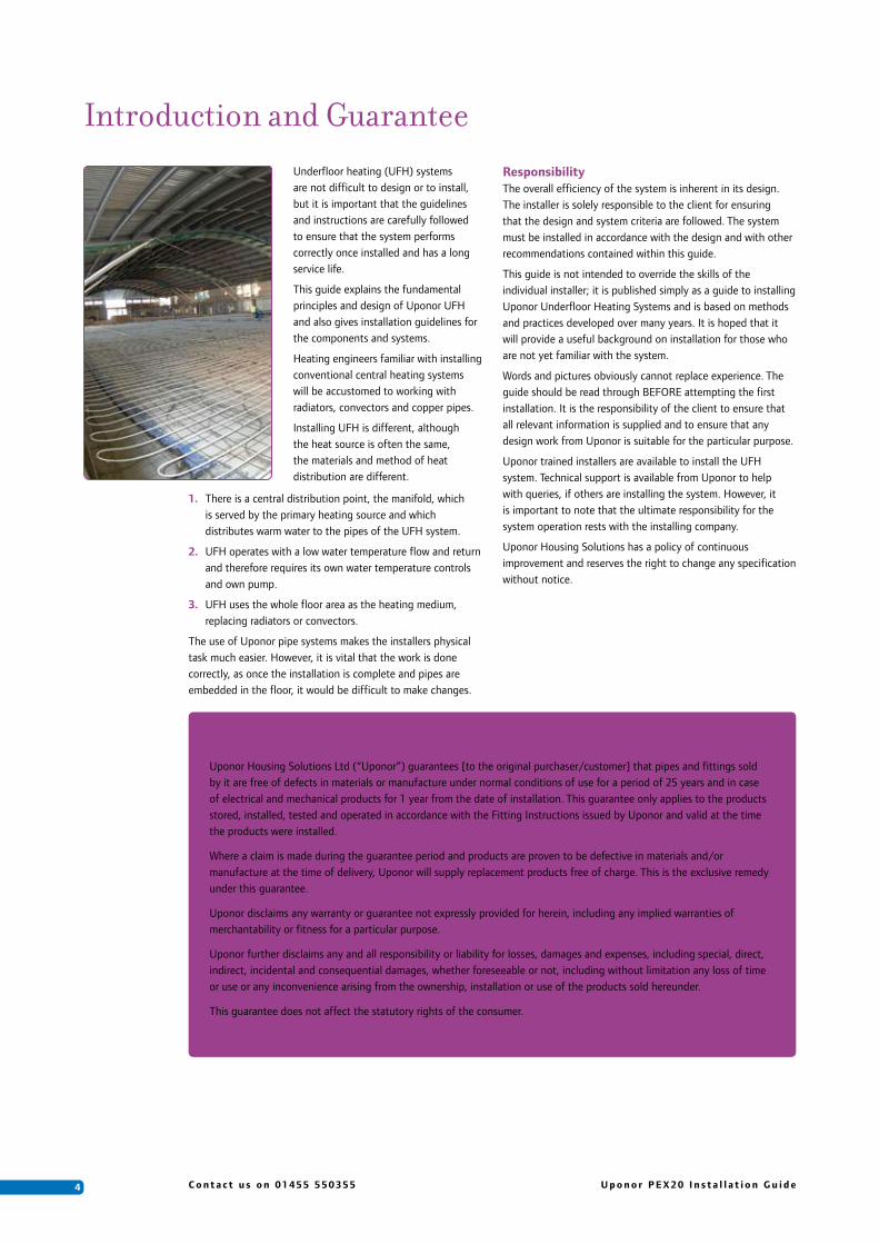
Underfloor heating (UFH) systems are not difficult to design or to install, but it is important that the guidelines and instructions are carefully followed to ensure that the system performs correctly once installed and has a long service life.
This guide explains the fundamental principles and design of Uponor UFH and also gives installation guidelines for the components and systems.
Heating engineers familiar with installing conventional central heating systems will be accustomed to working with radiators, convectors and copper pipes.
Installing UFH is different, although the heat source is often the same, the materials and method of heat distribution are different.
1. There is a central distribution point, the manifold, which is served by the primary heating source and which distributes warm water to the pipes of the UFH system.
2. UFH operates with a low water temperature flow and return and therefore requires its own water temperature controls and own pump.
3. UFH uses the whole floor area as the heating medium, replacing radiators or convectors.
The use of Uponor pipe systems makes the installers physical task much easier. However, it is vital that the work is done correctly, as once the installation is complete and pipes are embedded in the floor, it would be difficult to make changes.
Introduction and GuaranteeResponsibilityThe overall efficiency of the system is inherent in its design. The installer is solely responsible to the client for ensuring that the design and system criteria are followed. The system must be installed in accordance with the design and with other recommendations contained within this guide.
This guide is not intended to override the skills of the individual installer; it is published simply as a guide to installing Uponor Underfloor Heating Systems and is based on methods and practices developed over many years. It is hoped that it will provide a useful background on installation for those who are not yet familiar with the system.
Words and pictures obviously cannot replace experience. The guide should be read through BEFORE attempting the first installation. It is the responsibility of the client to ensure that all relevant information is supplied and to ensure that any design work from Uponor is suitable for the particular purpose.
Uponor trained installers are available to install the UFH system. Technical support is available from Uponor to help with queries, if others are installing the system. However, it is important to note that the ultimate responsibility for the system operation rests with the installing company.
Uponor Housing Solutions has a policy of continuous improvement and reserves the right to change any specification without notice.
Guarantee
Uponor Housing Solutions Ltd (“Uponor”) guarantees [to the original purchaser/customer] that pipes and fittings sold by it are free of defects in materials or manufacture under normal conditions of use for a period of 25 years and in case of electrical and mechanical products for 1 year from the date of installation. This guarantee only applies to the products stored, installed, tested and operated in accordance with the Fitting Instructions issued by Uponor and valid at the time the products were installed.
Where a claim is made during the guarantee period and products are proven to be defective in materials and/or manufacture at the time of delivery, Uponor will supply replacement products free of charge. This is the exclusive remedy under this guarantee.
Uponor disclaims any warranty or guarantee not expressly provided for herein, including any implied warranties of merchantability or fitness for a particular purpose.
Uponor further disclaims any and all responsibility or liability for losses, damages and expenses, including special, direct, indirect, incidental and consequential damages, whether foreseeable or not, including without limitation any loss of time or use or any inconvenience arising from the ownership, installation or use of the products sold hereunder.
This guarantee does not affect the statutory rights of the consumer.

5U p o n o r P E X 2 0 I n s t a l l a t i o n G u i d e C o n t a c t u s o n 0 1 4 5 5 5 5 0 3 5 5
1. Underfloor Heating Design Principles
Space HeatingWhatever the method used, the purpose of all space heating is to create an acceptable level of human comfort within a defined area. “Comfort” however, is a subjective concept. It will vary from person to person according to their age and activity level. There is therefore no universal ideal design temperature for all occasions - a sheltered housing project may require air temperatures of 21OC, while just 15OC may be adequate in a gymnasium or indoor sports hall.
PrinciplesThe principle of UFH is very simple. Rather than mount metal panels on walls, pipes are laid in the floor and warm water circulated so that the floor effectively becomes a large radiator. Because the floor is so large compared to a normal wall-mounted radiator, it needs to run only a few degrees above the air temperature to provide enough warmth to gently heat the whole room.
The primary aim of the floor heating design is to create an even, uniform surface temperature across the entire floor area within the building in order to ensure a consistent comfort level throughout the structure. When the floor temperature is higher than the air temperature, the floor will emit mainly radiant heat. The heat output from the floor is directly related to the temperature of the floor and that of the surrounding air.
Loops of pipes are normally installed beneath the whole floor area. These loops are connected to a central manifold, which is supplied with hot water from a suitable heat source - such as a boiler or heat pump - heat pumps are becoming ever more popular due to the potential energy savings. Usually, with boilers as the heat source, the central heating water is mixed before it reaches the manifold to reduce the water temperature to that suitable for the UFH system. Controls reduce the water temperature to maintain the correct design temperature and pump the warm water through the UFH pipes.
Heating with UFHUFH is a true radiant system and heats from floor to ceiling. UFH avoids wasted heat at high level and since the whole floor is heated evenly, optimum comfort is achieved everywhere in the room.
In fact, the room thermostat can be set 1 – 2OC lower than a radiator system and the room will still feel more comfortable! Running the system at a lower temperature and reducing the heat wasted at levels above head height makes for significant savings on fuel costs. The exact savings that can be expected are difficult to determine, as there are operational factors that also need to be considered.
Heat OutputsIt is the clients responsibility to check that heat losses of the building, carried out by a heating consultant or engineer, are compatible with the outputs given.
Generally, the maximum output from an UFH system is often stated at between 70 and 100 W/m2. The actual output achieved is a direct relationship between the difference in floor surface and room air temperatures. The floor construction, floor covering material, pipe size, pipe spacing, and the temperature
of water circulating through the UFH pipes are major factors that determine the floor surface temperature.
When designing conventional heating systems it is necessary to know the required heat output to be able to size the heat emitter. However, for UFH the size of the emitter is fixed - it is the floor area. Hence, the heat output is a function of the operating temperature of the floor, the floor area, and room air temperature.
Given the low U-values stipulated in current Building Regulations, it is unusual to require outputs greater than 70W/m2, based on a 20OC internal design temperature. It is important to note that poorly insulated buildings, conservatories, areas with high ceilings and rooms with high internal temperature requirements, may require supplementary heating during mid-winter conditions.
The heating consultant or engineer should provide heat loss calculations. Heat losses are calculated in the conventional way and the boiler size will be similar whether UFH or other heating system is used.
Uponor will specify maximum heat outputs for the floor and air temperatures specified. Providing the project complies with current building regulations, particularly with regard to thermal insulation levels, these outputs should be more than adequate to meet heat losses and provide full comfort conditions.
Design LimitsEstablishing the correct operating temperature for the floor surface is a balance between not having the temperature so high that it causes discomfort, but high enough so that sufficient heat output is provided to meet the calculated heat losses. BS EN 1264-2:1997 states that the ‘physiologically agreed’ maximum floor surface temperature is 9OC above the room temperature. This results in a maximum floor surface temperature of 29OC in typically occupied areas with a room temperature of 20OC. A 9OC temperature difference will equate to a floor heat output of 100W/m2.
Floor Construction TypeFloor construction is another key factor in the design. Screed floors, suspended wooden floors and floating floors all require individual consideration to ensure optimum performance and an even distribution of heat across the surface of the floor.
The screed or solid floor system relies on the conductivity of the screed or concrete to conduct the heat from the pipe surface to the underside of the floor finish. Because the screed is itself heated to conduct the heat it tends to store considerable amounts of heat and thus provides a slow response when both heating up and cooling down.
Timber floor systems rely on the conductivity of components fitted within the floor to conduct the heat from the pipe to the underside of the floor finish. In order to achieve good results the pipes must transfer their heat evenly to the floor surface. Inadequate heat dissipation and hot spots can cause unsightly shrinkage, particularly with natural wood boards. Because the mass of a timber floor structure is less than the mass of a screed floor, the system response of a timber floor system is usually much faster.
This section provides information about how the underfloor heating (UFH) system is designed and highlights points to consider before the design work commences.
1
6 C o n t a c t u s o n 0 1 4 5 5 5 5 0 3 5 5 U p o n o r P E X 2 0 I n s t a l l a t i o n G u i d e
The floating floor system is predominantly suitable for sheet flooring or some stronger laminates. The grooved insulation is structural, usually supplied in 50mm thickness and laid on top of a prepared base. Additional insulation may be required to ensure compliance with Building Regulations and to minimize downward losses.
Water Temperature ControlTo meet the requirements of BS EN 1264, water temperature control must be provided. This ensures that maximum floor surface temperatures are not exceeded. The ‘UNIset MINI’ and the ‘UP36 Controller’ are designed to mix and control the primary heat source flow water temperature with the UFH return water temperature, to a requirement suitable for the UFH system.
Boiler/Heat SourceTraditionally, the primary heat source has been a boiler, producing low temperature hot water for the system. Modern high efficiency condensing boilers are ideal for UFH as the low water temperatures allow the boiler to work in condensing mode.
If the heat source is able to provide and maintain a constant or variable water temperature at the requirement for the UFH, it may not be necessary to have any further water temperature controls.
If there are no services, other than the UFH, being supplied by the boiler and water temperature controls are used, it may be necessary to have a heat sink, such as a towel rail, prior to the UFH mixing valve to prevent the boiler from cycling and cutting out on high limit.
However, ultimately, careful thought must be given when choosing your boiler, as not all units are compatible. Always check the specific application with the boiler manufacturer.
More recently, other sources have become available which are ideal for UFH such as ground source heat pumps.
Calculating Size of UFH PumpThe smooth inner surface and diameter of 20mm PEX pipe reduces the pressure loss, optimising the pipe length that can be used. The temperature drop across the pipe loop and the maximum required heat emission determines the water flow rate required through the pump. The Uponor pre-assembled UNIsets are supplied complete with a suitably sized UFH circulating pump.
Pipe SpacingUponor has established that 20mm UFH pipes should generally be spaced at 300mm centres to achieve optimum working efficiency. In areas of high heat loss, the pipe spacing may be decreased accordingly, (e.g. between 150 - 200mm centres), depending on the fixing system and floor system in use. (Ensure there is sufficient pipe prior to installing at reduced pipe centres).
Pipes should be spaced 150mm away from the wall edges. Subsequently, in modern well-insulated buildings the UFH pipe is generally installed at 300mm centres across the active floor area. In areas with highly glazed walls, conservatories, high ceiling rooms, bathrooms or poorly insulated buildings, the pipes can be installed between 150mm and 200mm centres across the peripheral zone (an area of 1m from the external
wall edges) to offset the increased heat losses. In extreme cases of high heat loss (conservatories) or when using a ground source heat pump as the heat source, the UFH pipe can be installed at 200mm centres throughout the whole active floor area. Although, on timber suspended floors and floating floor installations the pipes are normally fixed at 300mm centres.
In order to calculate the amount of pipe required, the following guide can be used:
Important Note:When calculating your pipe requirement, remember to add the feed/tail pipe lengths, between manifold and room, to your calculations.
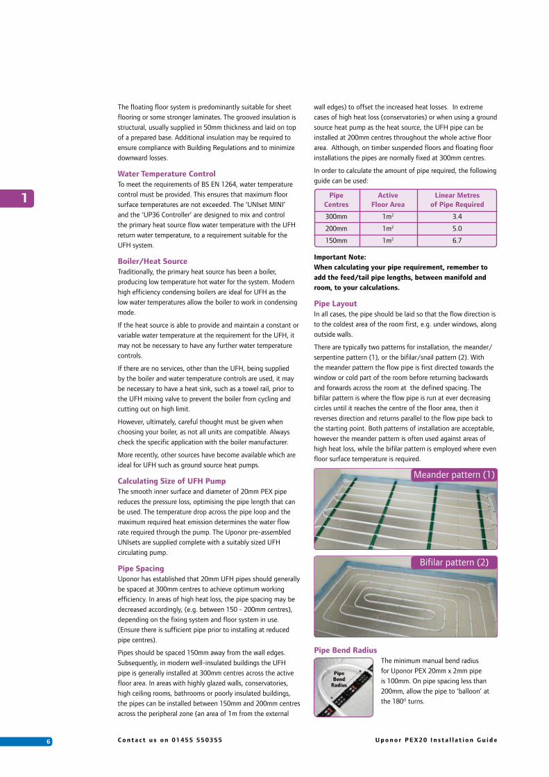
Pipe LayoutIn all cases, the pipe should be laid so that the flow direction is to the coldest area of the room first, e.g. under windows, along outside walls.
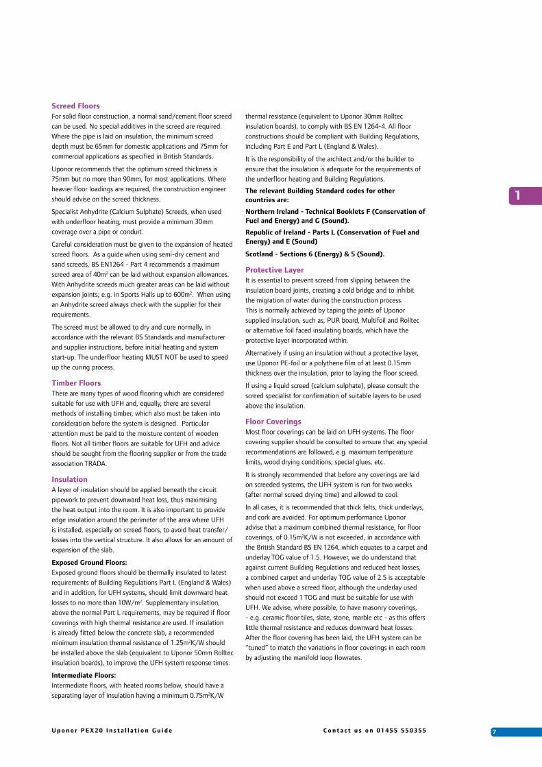
There are typically two patterns for installation, the meander/serpentine pattern (1), or the bifilar/snail pattern (2). With the meander pattern the flow pipe is first directed towards the window or cold part of the room before returning backwards and forwards across the room at the defined spacing. The bifilar pattern is where the flow pipe is run at ever decreasing circles until it reaches the centre of the floor area, then it reverses direction and returns parallel to the flow pipe back to the starting point. Both patterns of installation are acceptable, however the meander pattern is often used against areas of high heat loss, while the bifilar pattern is employed where even floor surface temperature is required.
Pipe Bend RadiusThe minimum manual bend radius for Uponor PEX 20mm x 2mm pipe is 100mm. On pipe spacing less than 200mm, allow the pipe to ‘balloon’ at the 180O turns.
Pipe Active Linear Metres Centres Floor Area of Pipe Required
300mm 1m2 3.4
200mm 1m2 5.0
150mm 1m2 6.7
Meander pattern (1)
Bifilar pattern (2)
1
7U p o n o r P E X 2 0 I n s t a l l a t i o n G u i d e C o n t a c t u s o n 0 1 4 5 5 5 5 0 3 5 5
Screed FloorsFor solid floor construction, a normal sand/cement floor screed can be used. No special additives in the screed are required. Where the pipe is laid on insulation, the minimum screed depth must be 65mm for domestic applications and 75mm for commercial applications as specified in British Standards.
Uponor recommends that the optimum screed thickness is 75mm but no more than 90mm, for most applications. Where heavier floor loadings are required, the construction engineer should advise on the screed thickness.
Specialist Anhydrite (Calcium Sulphate) Screeds, when used with underfloor heating, must provide a minimum 30mm coverage over a pipe or conduit.
Careful consideration must be given to the expansion of heated screed floors. As a guide when using semi-dry cement and sand screeds, BS EN1264 - Part 4 recommends a maximum screed area of 40m2 can be laid without expansion allowances. With Anhydrite screeds much greater areas can be laid without expansion joints; e.g. in Sports Halls up to 600m2. When using an Anhydrite screed always check with the supplier for their requirements.
The screed must be allowed to dry and cure normally, in accordance with the relevant BS Standards and manufacturer and supplier instructions, before initial heating and system start-up. The underfloor heating MUST NOT be used to speed up the curing process.
Timber FloorsThere are many types of wood flooring which are considered suitable for use with UFH and, equally, there are several methods of installing timber, which also must be taken into consideration before the system is designed. Particular attention must be paid to the moisture content of wooden floors. Not all timber floors are suitable for UFH and advice should be sought from the flooring supplier or from the trade association TRADA.
InsulationA layer of insulation should be applied beneath the circuit pipework to prevent downward heat loss, thus maximising the heat output into the room. It is also important to provide edge insulation around the perimeter of the area where UFH is installed, especially on screed floors, to avoid heat transfer/losses into the vertical structure. It also allows for an amount of expansion of the slab.
Exposed Ground Floors:Exposed ground floors should be thermally insulated to latest requirements of Building Regulations Part L (England & Wales) and in addition, for UFH systems, should limit downward heat losses to no more than 10W/m2. Supplementary insulation, above the normal Part L requirements, may be required if floor coverings with high thermal resistance are used. If insulation is already fitted below the concrete slab, a recommended minimum insulation thermal resistance of 1.25m2K/W should be installed above the slab (equivalent to Uponor 50mm Rolltec insulation boards), to improve the UFH system response times.
Intermediate Floors:Intermediate floors, with heated rooms below, should have a separating layer of insulation having a minimum 0.75m2K/W
thermal resistance (equivalent to Uponor 30mm Rolltec insulation boards), to comply with BS EN 1264-4. All floor constructions should be compliant with Building Regulations, including Part E and Part L (England & Wales).
It is the responsibility of the architect and/or the builder to ensure that the insulation is adequate for the requirements of the underfloor heating and Building Regulations.
The relevant Building Standard codes for other countries are:
Northern Ireland - Technical Booklets F (Conservation of Fuel and Energy) and G (Sound).
Republic of Ireland - Parts L (Conservation of Fuel and Energy) and E (Sound)
Scotland - Sections 6 (Energy) & 5 (Sound).
Protective LayerIt is essential to prevent screed from slipping between the insulation board joints, creating a cold bridge and to inhibit the migration of water during the construction process. This is normally achieved by taping the joints of Uponor supplied insulation, such as, PUR board, Multifoil and Rolltec or alternative foil faced insulating boards, which have the protective layer incorporated within.
Alternatively if using an insulation without a protective layer, use Uponor PE-foil or a polythene film of at least 0.15mm thickness over the insulation, prior to laying the floor screed.
If using a liquid screed (calcium sulphate), please consult the screed specialist for confirmation of suitable layers to be used above the insulation.
Floor CoveringsMost floor coverings can be laid on UFH systems. The floor covering supplier should be consulted to ensure that any special recommendations are followed, e.g. maximum temperature limits, wood drying conditions, special glues, etc.
It is strongly recommended that before any coverings are laid on screeded systems, the UFH system is run for two weeks (after normal screed drying time) and allowed to cool.
In all cases, it is recommended that thick felts, thick underlays, and cork are avoided. For optimum performance Uponor advise that a maximum combined thermal resistance, for floor coverings, of 0.15m2K/W is not exceeded, in accordance with the British Standard BS EN 1264, which equates to a carpet and underlay TOG value of 1.5. However, we do understand that against current Building Regulations and reduced heat losses, a combined carpet and underlay TOG value of 2.5 is acceptable when used above a screed floor, although the underlay used should not exceed 1 TOG and must be suitable for use with UFH. We advise, where possible, to have masonry coverings, - e.g. ceramic floor tiles, slate, stone, marble etc - as this offers little thermal resistance and reduces downward heat losses. After the floor covering has been laid, the UFH system can be “tuned” to match the variations in floor coverings in each room by adjusting the manifold loop flowrates.
1

8 C o n t a c t u s o n 0 1 4 5 5 5 5 0 3 5 5 U p o n o r P E X 2 0 I n s t a l l a t i o n G u i d e
Before InstallingPrior to installation, it is important that the installer makes the following checks to ensure the project runs as smoothly as possible:
1. All the materials and the quantities are correct and on site against the delivery note and against the material schedule.
2. All other trades involved in the installation are fully conversant with component layout and positioning. For example, for first fix wiring, the electrician should know the positions of the room thermostats, water temperature controls, time clocks, etc (see Chapter 6 for further details).
3. Sub-floors are clean, level and are correct for the depth of construction needed to incorporate the underfloor heating.
4. Ensure all other trades not involved with the installation are notified and excluded from the installation area before and during installation.
It is important to read in full and understand all installation instructions offered before commencing installation.
First Time Tips• For first time installers, laying the pipe needs two people. One to hold the pipe coil and un-rolling it, with the second person, a couple of metres behind, securing the pipe in position. For ease of clipping pipe into insulation we would advise investing in a Uponor Kombi-tacker gun (UK001007).
• Only one person is needed if using a pipe de-coiler. Place the de-coiler in another room and pull the pipe off as required.
• Check which water temperature controls are to be used and where they are to be positioned to ensure that enough room is allowed for the manifold.
• Check the position of the manifold and fit the manifold before laying the pipe work.
• Ensure that the pipe does not become twisted when handling as it can become awkward to install. The pipe will twist slightly on bends but the print line is a good guide to assist in laying the pipe.
• During cold conditions, installation and handling will be easier if the pipes are stored overnight in a heated room before installing.
• To avoid kinks always pull the pipe to shape rather than bend and try and force into position.
• If the pipe does become kinked, the kink can be removed by gently heating the kink/crease with a warm air gun (NEVER a naked flame) until the pipe is hand warm, 40-50OC.
Contact Uponor for further technical advice if necessary.
• Always cut the pipe square and use a plastic pipe cutter (Item no: 010620) ensuring that there are no burrs on the pipe ends. It is important to achieve a clean cut at right angles to the pipe.
• Allow a minimum 150mm from the wall edges for the first pipe run.
Connection to Primary CircuitEach manifold and/or water temperature control station must be served by a flow and return from the central heating source and primary heating circuit. Where the heat source is providing water at the correct temperature for the UFH system, the manifold can be connected directly onto the primary pipework.
When using the pre-assembled UNIset water temperature controller and a single manifold, connections can be made directly onto the manifold. Alternatively, water temperature controls can be located remote from manifold(s). If located remotely, the interconnecting pipe work should be sized in accordance with required water flow rate and the available pump head.
Unless otherwise specified or requested, Uponor does not design or supply the primary supply pipe work.
As a precaution, Uponor recommends that a by-pass be fitted in the primary pipework.
2. Preparation and Installation Principles
2

9U p o n o r P E X 2 0 I n s t a l l a t i o n G u i d e C o n t a c t u s o n 0 1 4 5 5 5 5 0 3 5 5
2
Tools Required Screed Floor Timber Suspended Floor Floating Floor - Heat Emission Plates
Uponor plastic pipe cutter Yes Yes Yes
Drill and necessary drill bits Yes Yes Yes
Suitable wall fixings (for manifold) Yes Yes Yes
Plumbers wrench/grips Yes Yes Yes
Kombi Tacker Gun Optional
Hot wire cutter with 20mm head Recommended
Hand saw or sharp bladed knife Yes
Hammer Yes
Sharp wood saw Yes
Chisel Yes
Hacksaw Yes
Stanley knife Yes
Staple gun or tacks Yes
4mm Allen key(for manifold loop balancing) Yes Yes Yes
10mm spanner(for UNIset MINI only) Yes Yes Yes

1 0 C o n t a c t u s o n 0 1 4 5 5 5 5 0 3 5 5 U p o n o r P E X 2 0 I n s t a l l a t i o n G u i d e
Uponor WGF manifolds are manufactured from dezincification resistant brass material and are for the distribution of hot and cold water in the area of radiant heating and cooling systems. The pipe loops are secured to these manifolds by the compression adaptors supplied. Manifolds are supplied in pairs, i.e. a flow and return manifold. Manifold sections of 2, 3 and 4 ports are available, and can be threaded together and built-up on a modular basis to serve any number of loops up to a maximum of 12 outlets. Sealing is achieved with o-rings, which must not be visible after connecting and tightening the modules.
LocationManifold locations need to be positioned strategically and as centrally as possible, in order to reduce the amount and length of pipe tails and uncontrolled energy from pipes passing through heated areas en-route to other rooms/areas. It is important to select the manifold position at the beginning of the design process. If you have received a design and quotation from Uponor, manifold locations will be specified on the quotation.
Ensure there is sufficient height available, from the floor level to the lower return manifold, to enable easy connection of the UFH pipework (minimum 300mm). Although it is not necessary to have the manifold on show, it should be accessible for maintenance and servicing. Typical locations include; understairs cupboard, utility rooms, airing cupboards and cloaks cupboards.
Flow ManifoldThe flow to each 20mm PEX pipe loop is controlled by an on/off valve on the flow manifold. The valves allow each loop to be isolated if required. The hand wheels on the flow manifold may be replaced by electro-thermal actuators. The actuators are controlled by room thermostats to provide Individual Room Control. Alternatively, all the loops can
be controlled together via a single programmable thermostat controlling a 2-port motorised zone valve or similar device.
Return ManifoldOn the return manifold, each loop is controlled by a lockshield type balancing valve. This valve allows the flow rate to be adjusted as necessary to balance the water flow between different loop lengths. For initial balancing settings, the number of valve turns for each loop (dependent on the loop length) is given in the Uponor technical print out supplied for each project. Once the system is running, a final
adjustment can be made using this valve by balancing each loop to match individual room or zone requirements. Usually, a maximum temperature drop of 5°C for domestic projects and a 7.5°C for commercial projects should be allowed when setting these valves.
End CapsAn end cap is supplied to close off the open ends of the manifolds. This cap incorporates a port for connecting a hose union for filling the system. As the loops are filled, air is purged from the system and can escape via the end cap. The end cap should always be mounted with the fill port uppermost and also tightened until the o-ring is no longer visible. The end caps incorporate spare connections for the S90 or XL900 manifold by-pass.
Ball ValvesEach manifold group is supplied with two valves for mounting on the flow and return manifolds between the manifold and the pipes from the UFH water controls. Ensure that the larger end of the valve with the recess for the o-ring is mounted onto the manifold. The thread of the valve is 1” BSP for completing the connection. As standard straight pattern valves will be supplied, although angle pattern are available to special order.
O-Ring SealsO-Rings are supplied with the manifolds. These should not be removed! Always check that these are present before assembling. The manifold sections must always be tightened to ensure that the seals are NOT VISIBLE.
Support BracketsTwo support brackets with snap-fit clips are supplied for each manifold station to mount the assembly onto the wall. The bracket should be positioned on the wall and then the manifold pushed into the clips until the clips lock.
Assemble the manifold and fix to the wall using the support brackets. The lower manifold is staggered further out from the wall to allow the pipes from the higher manifold to pass behind.
Connecting to the manifoldWhen laying the UFH loops, the first pipe end should be connected to the manifold before the loop is laid. Push the pipe-end lying on the outer side of the coil through and behind the return manifold and connect as per instructions below.
If insulating the feed pipes with Uponor conduit, we advise sliding this over the UFH pipe prior to connecting onto the manifold.
3. Installation of:
3
WGF Manifold

1 1U p o n o r P E X 2 0 I n s t a l l a t i o n G u i d e C o n t a c t u s o n 0 1 4 5 5 5 5 0 3 5 5
Connecting Uponor PEX PipesEnsure a pipe bend support is fitted where the pipe exits the floor and turns up to the manifold. Line the pipe end up with the threaded port on the manifold and cut the pipe end square using plastic pipe cutters.
1. Push the nut and olive onto the end of the pipe.
2. Push the insert fully into the pipe end in order to get a secure joint.
3. Slide both the ring and nut onto the manifold port. Tighten the nut by hand.
4. Then tighten a further half turn with a spanner.
3
2 3 41
1 2 C o n t a c t u s o n 0 1 4 5 5 5 5 0 3 5 5 U p o n o r P E X 2 0 I n s t a l l a t i o n G u i d e
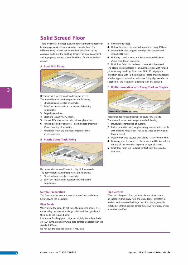
There are several methods available for securing the underfloor heating pipe work within a screed or concrete floor. The different fixing systems can be used individually or in any combination to suit the building design. The most convenient and appropriate method should be chosen for the individual project.
A Steel Grid Fixing
Recommended for standard sand/cement screed.The above floor section incorporates the following:1 Structural concrete slab or oversite.2 Sub-floor insulation in accordance with Building
Regulations.3 Polyethylene sheet.4 Steel grid (usually A142 mesh).5 Uponor PEX pipe secured with wire or plastic ties.6 Finishing screed or concrete. Recommended thickness
75mm from top of insulation.7 Final floor finish laid in direct contact with the screed/concrete.
B Plastic Clamp Track Fixing
Recommended for sand/cement or liquid flow screeds.The above floor section incorporates the following:1 Structural concrete slab or oversite.2 Sub-floor insulation in accordance with Building
Regulations.
3 Polyethylene sheet.4 Flat plastic clamp track with clip positions every 150mm.5 Uponor PEX pipe snapped into cliprail or secured with
individual U-clips.6 Finishing screed or concrete. Recommended thickness
75mm from top of insulation.7 Final floor finish laid in direct contact with the screed.The plastic track illustrated is in 600mm sections with hinged joints for easy handling. Fixed onto EPS 150 polystyrene insulation board with ‘u’ holding clips. Please check suitability of other types of insulation. Individual fixing clips can also be supplied for the location of single pipes in any position.
C Rolltec Insulation with Clamp Track or Staples
Recommended for sand/cement or liquid flow screeds.The above floor section incorporates the following:1 Structural concrete slab or oversite.2 Rolltec insulation with supplementary insulation to comply
with Building Regulations. Foil to be taped on every joint (flow screeds).
3 Uponor PEX pipe secured with Clamp Track or Kombi Klips.4 Finishing screed or concrete. Recommended thickness from
the top of the insulation depends on type of screed.5 Final floor finish laid in direct contact with the screed or
concrete.
Surface PreparationThe floor must be level and swept clean of dust and debris before laying the insulation.
Pipe BendsWhen laying the pipe, do not force the pipe into bends. It is easier to lay the pipe with a large radius and then gently pull the pipe to the required bend. It is normal for the pipe to bulge out slightly like a ‘light bulb’ on 180O turns, especially where pipe centres are closer than the standard 300mm.Do not pull the pipe too tight or it may kink.
Pipe CentresWhen installing onto floor grade insulation, pipes should be spaced 150mm away from the wall edges. Thereafter, in modern well-insulated buildings the UFH pipe is generally installed at 300mm centres across the active floor area, unless otherwise specified.
3
Solid Screed Floor
Staple fixings (Kombi Klips) shown

1 3U p o n o r P E X 2 0 I n s t a l l a t i o n G u i d e C o n t a c t u s o n 0 1 4 5 5 5 5 0 3 5 5
Installation
• Fix the edge insulation continuously around all internal and external wall edges, using the adhesive backing. When installed correctly the PE-skirt will be facing out from the wall and the embossed ‘Uponor’ will be legible.
Once the screed has dried and cured, the edge strip can be trimmed down.
• Lay the floor insulation over the entire floor area butting up to the edge strip, ensuring the PE skirt is overlapped and taped onto the floor insulation. If using Uponor insulation or another foil faced insulation board, tape the joints of all adjoining sections of insulation together to prevent screed slipping down between sheets of insulation and creating a cold bridge. Alternatively, lay a protective layer over the insulation (see chapter 2).
• Fix the manifold into position, ensuring there is sufficient room to connect the water temperature controls and flow and return pipework.
• If using Clip Rail & U-clips, lay the rail across the floor to create a matrix for the UFH pipe. Use the self-adhesive backing to hold the rail onto the insulation. For ease of pipe installation, set the rail out on the insulation at a maximum 500mm spacing from two opposite wall edges and a maximum 1000mm spacing between the two edge rails (see meander picture overleaf). This pattern is for the meander pipe installation layout, ensuring the clip rail is at a 90O angle to the coldest external wall.
Alternatively, if you wish to lay the pipe in a bifilar pattern (see bifilar picture overleaf), lay the clip rail over the insulation in a cross/star pattern with each clip rail strip converging in the centre of the floor area to be heated.
Once you are happy with the clip rail layout in relation to your proposed pipe configuration and routes, fix the rail permanently to the insulation by pushing the ‘U’-clips through the holes provided in the clip rail at the leading and trailing end of the rail. If the length of rail exceeds 1m use additional U-clips at 500mm intervals. Insert u-clips at a 45O angle to give maximum hold..
On the actual pipe bends you should use the U-clips directly over the pipe and into the insulation for extra hold.
If the floor grade insulation is already installed below the floor slab and the additional insulation laid over the concrete slab is not sufficient to fix Uponor U-clips, we would advise fixing the rail directly to the sub concrete floor using suitable floor fixings (screws and plugs).
If using the Kombi Klips to fasten the pipe to the floor grade insulation, clip the pipe at approximately 500mm intervals. More clips will be necessary on the pipe bends. Minimum 35mm insulation depth is required for the Kombi long and 25mm for the short. To assist with fixing the Kombi clips into the insulation we would advise using the Uponor Kombi Tacker Gun (Item no. UK001007)
3
Clip Rail Fixing
Kombi Klip Fixing

1 4 C o n t a c t u s o n 0 1 4 5 5 5 5 0 3 5 5 U p o n o r P E X 2 0 I n s t a l l a t i o n G u i d e
For example, if installing at 300mm centres across the floor area, follow the same route at 600mm centres. Continue spiralling this way until reaching the centre of the area. At this point turn back on yourself, making a hairpin turn and begin laying the pipe outwards centrally between the pipes already fixed on your inward journey, thus ensuring even 300mm pipe centres across the whole floor area and more importantly an even floor temperature. On returning back to the manifold connect the tail end pipe to the corresponding return port on the manifold.
Screed Expansion JointsWhere pipes are to cross over a screed expansion joint, use a small section of conduit over the pipe, up to a minimum of 200mm either side of the joint. Any crossing of a construction joint should be at 90O to the line of the joint.
InspectionOnce the pipes have been laid, inspect the system to ensure all is as it should be.
Where used, snip back all sharp edges of mesh that may contact the pipe. Clip down any sections that have lifted to stop the pipe being too close to the finished surface.
Pressure TestingOnce all the pipes have been laid and connected to the manifold, fill and pressure test the system as per Chapter 7.
Sand-Cement ScreedLay the screed as soon as possible to protect the pipes. At all times avoid unnecessary foot traffic.
Installing the Meander Pattern (1)Once you have entered the room/area to be covered, first lay the flow pipe around the perimeter with 150mm gap from the wall to the coldest area and then meander up and down across the floor area back towards the point of entry, following the same route back to the manifold, clipping the pipe as necessary depending on the chosen method of fixing. On returning back to the manifold connect the tail end of the pipe to the corresponding return port on the manifold.
Installing the Bifilar Pattern (2)Once you have entered the room/area to be covered, lay the pipe around the perimeter of the active floor area to be covered, maintaining 150mm gap from the wall edge and clipping the pipe as necessary. When you have circled the area and are back at your starting point, follow the same route around, but this time, at two times the design pipe spacing.
3
Laying the UFH PipeIn order to prevent the floor from overheating directly below the manifold or through doorways, where pipes are congested together, we would advise insulating the pipe, especially if they are not used to heat the room through which they pass.
• Identify each floor area to be covered by each coil/loop of UFH pipe. If you have had a design prepared by Uponor, the rooms to be heated and the coil lengths allocated to each area will be identified on your design layout drawing(s).
• When installing the pipe it is important to ensure the pipes do not cross over each other, therefore time should be spent, before actually laying any pipe, configuring the route for the feed pipes from the manifold location to their respective area/room to be heated.
• Typically, feed pipes pass through door openings, etc. However, where possible, particularly to areas adjoining the manifold location, feed pipes could be taken directly through partition walls and into their respective rooms. This will also help alleviate any congestion around the manifold location. Ensure all holes drilled are below the screed floor finished level. Also, when threading the pipe through the hole ensure it has been capped off and there
are no sharp edges, which could score and damage the pipe. It is recommended that the UFH pipes, when passing through walls, are sleeved with Uponor protective conduit.
• Once you have a clear picture of the installation, you can begin to install and lay the pipe. Firstly thread the first coil end behind the return manifold and connect onto the manifold flow port. If passing through a partition wall first thread the pipe through the hole and up behind the return manifold.
For 20mm PEX pipe, ‘pipe bend supports’ must be fitted on every loop at the point where the pipes rise from the floor/insulation and up to connect to the manifold, i.e. 2 required per loop.
In all cases, the pipe should be laid so that the flow direction is to the coldest area of the room first, for example, under windows and along external walls.
To assist with installation, Uponor pipe is marked at every metre length. It is good practice to make a note of the starting metre at the manifold and keep referencing how much pipe has been laid whilst installing over the intended floor area. This will help ensure you leave sufficient pipe to return to the manifold. Each loop should be installed without any joints in the floor.
Meander pattern (1)
Bifilar pattern (2)
1 5U p o n o r P E X 2 0 I n s t a l l a t i o n G u i d e C o n t a c t u s o n 0 1 4 5 5 5 5 0 3 5 5
3
Timber Suspended Floor
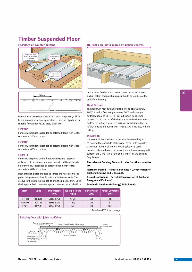
Uponor have developed various heat emission plates (HEP’s) to suit many timber floor applications. There are 3 plate sizes suitable for Uponor PEX20 pipe, as follows:
HEP300For use with timber suspended or battened floors with joists/supports at 300mm centres.
HEP400For use with timber suspended or battened floors with joists/supports at 400mm centres.
HEP411For use with sprung timber floors with battens spaced at 411mm centres, such as Junckers Unobat and Blubat Sports Floor Systems, suspended or battened floors with joists/supports at 411mm centres.
Heat emission plates are used to spread the heat evenly, the plates being secured directly onto the battens or joists. The groove in the plate is designed to grip the pipe securely. Once the loops are laid, connected up and pressure tested, the floor
Uponor PEX pipes laid in special grooves
in the heatemission plates
Heat EmissionPlates
Battens nailedto joints at
300mm centres
HEP300’s on counter battens HEP400’s on joints spaced at 400mm centres
deck can be fixed to the batten or joists. All other services such as cables and plumbing pipes should be laid before the underfloor heating.
Heat OutputThe maximum heat output available will be approximately 70W/m2 with a floor temperature of 26°C and a design air temperature of 20°C. This output should be checked against the heat losses of the building given by the Architect and/or consulting engineer. This is particularly important in refurbishments and rooms with large glazed areas and/or high ceilings.
InsulationIt is essential that insulation is installed between the joists, as close to the underside of the plates as possible. Typically, a minimum 100mm of mineral wool insulation is used, however, where relevant, the insulation used must comply with current Part L and Part E (England & Wales) of the Building Regulations.
The relevant Building Standard codes for other countries are:
Northern Ireland - Technical Booklets F (Conservation of Fuel and Energy) and G (Sound).
Republic of Ireland - Parts L (Conservation of Fuel and Energy) and E (Sound)
Scotland - Sections 6 (Energy) & 5 (Sound).
Item Code Dimensions No Pipe Tracks Plates/Pack *Pack Coverage (mm) (qty) (qty) (m2)
HEP300 010601 280 x 1150 Single 40 16 HEP400 801122 380 x 1150 Two 20 11 HEP411 010598 405 x 1150 Two 28 16.3
Existing floor with joists at 400mm
Joists @ 400mm Centres
Minimum depth of joist is 200mm to allow for 25mmdeep notching.
Floor covering typically chipboard max thickness 34mm HEP400
Heat Emission Plate
Insulation (by others)
Heating Pipework fitted at 200mm centres
* Based on 80% floor coverage

1 6 C o n t a c t u s o n 0 1 4 5 5 5 5 0 3 5 5 U p o n o r P E X 2 0 I n s t a l l a t i o n G u i d e
3
Laying the Pipe for Heat Emission Plates
• The plates are for heat distribution only and are not structural. They are easily damaged and it is very important that no other trades are allowed where the UFH is being installed.
The heat emission plates normally cover approximately 80% of the floor area. Plates should never touch each other, as they expand when heated and can create noise.
Plates are only laid under straight runs of pipe.
• Ensure all insulation and the necessary battening work is installed and complete, prior to laying of the plates. If cross battening, this is best achieved using 25mm x 100mm battens. Leave the ends of the battens loose so that the pipe loop can be laid beyond the end of or under the cross batten. Fix batten ends before laying floor.
• Lay the heat emission plates across the joists without fixing, leaving a gap between the ends and sides of each plate. Check to ensure appropriate number of plates are evenly spread out across the entire area before fixing.
• Lay the first plates at each end of the room, leaving a minimum 300mm space from the wall edge, to enable the pipe to bend 180 degrees around. Thereafter space the plates out evenly ensuring gaps between plates are at least 10mm but less than 100mm. Use any sections of plates in the middle of the room. If the last plate is not against a wall, ensure the plate is set to a minimum of 300mm from the pipe bend radius, as shown above.
• When the room is evenly covered with plates fix them down with a staple gun or tacks.
• Careful consideration should be given to the location of plates around the manifold area and along feed pipe routes, where the UFH pipes congregate together, cross joists at right angles and are at reduced pipe centres.
Cutting PlatesThe plates are scored ¹⁄3 from one end of the plate and at ¹⁄6 from the other and are easily split along these score lines. Keep the pipe groove uppermost and sharply break the plate over a straight edge. If different lengths are required, score the plate deeply with a Stanley knife and cut along the pipe groove with a hacksaw.
Clean off the burrs in the pipe groove to prevent damage to the pipe.
Installation of Heat Emission Plates
min 300mm
When laying the pipe, do not force the pipe into bends. It is easier to lay the pipe with a large radius and gently pull the pipe to the required bend before pressing into the plate. It is normal for the pipe to bulge out slightly like a ‘light bulb’ on 180O turns.
Do not pull the pipe too tight or it may kink.
• Where possible, the design will ensure that the flow pipes are directed to the coldest part of the room. However, in suspended floors the pipe direction is dictated by the joist/batten direction.
• Identify each floor area to be covered by each coil/loop of UFH pipe (if you have received a design prepared by Uponor, the rooms to be heated and coils allocated can be identified on the design layout drawing).
• When installing the pipe it is important to ensure the pipes do not cross over each other, therefore time should be spent, before actually laying any pipe, configuring the
route for the feed pipes from the manifold location to their respective area/room to be heated.
• Typically, feed pipes from the manifold pass through door openings. However, where possible, to avoid any congestion around the manifold and unnecessary notching, particularly to rooms adjoining the manifold location, feed pipes can be taken directly through partition walls and into the respective room. Ensure any holes drilled are below the floor level. When threading the pipe through the hole, ensure it has been capped off and there are no sharp edges, which could score and damage the pipe. It is recommended that the UFH pipes, when passing through walls, are sleeved with Uponor protective conduit.
• Mark out, notch or drill holes in the joists in compliance with current Building Regulations. When cutting the joist or batten, we would advise preparing a 25mm deep x 60mm wide notch, enabling two pipes to pass over the joist side by side.

1 7U p o n o r P E X 2 0 I n s t a l l a t i o n G u i d e C o n t a c t u s o n 0 1 4 5 5 5 5 0 3 5 5
• Once you have a clear picture of the installation, you can begin to install and lay the pipe. Firstly thread the first coil end behind the return manifold and connect onto the flow port manifold. If passing through a partition wall, first thread the pipe through the hole and up behind the return manifold.
• For PEX pipe, ‘pipe bend supports’ must be fitted on every loop at the point where the pipes rise from the floor to connect to the manifold, i.e. 2 required per loop.
• Lay the pipe, pressing it into the plates by hand or gently by foot and meander the pipe up and down across the floor area towards the start position and manifold. Be careful not to bend the plates excessively, although it is normal for the plates to deflect a small amount.
• Do not pull the pipe tightly against notches to prevent additional stress on the pipe.
• To assist with installation, Uponor pipe is marked at every metre length. It is good practice to make a note of the starting metre at the manifold and keep referencing how much pipe has been laid whilst installing over the intended floor area. This will help ensure you leave sufficient pipe to return to the manifold. Each loop should be installed without any joints in the floor.
• Once the loop has been laid, take the pipe back to the manifold, following the same route out and connect the
tail pipe to the corresponding return port on the manifold. Before proceeding to the next loop, label the loop just installed. It is important that the flow direction in each loop of pipe is as per the design.
Inspection Once the pipes have been laid, it is important to inspect the system before laying the floor, to ensure the installation is correct and pipes are held firmly away from any possible damage.
Pressure TestingOnce all the pipes have been laid and connected to the manifold, fill & pressure test the system as per Chapter 7.
DeckingThe area should be decked out immediately after completing installation to protect the system. For safety reasons, foot traffic must be prevented until this is carried out. If necessary, the floor can be marked to show the pathway of the pipe runs and joists to assist the Floor Layer fixing down the floor.
SafetyIt is the responsibility of the installer to ensure that the system is installed in accordance with all relevant Health and Safety Regulations and requirements.
3
1 8 C o n t a c t u s o n 0 1 4 5 5 5 5 0 3 5 5 U p o n o r P E X 2 0 I n s t a l l a t i o n G u i d e
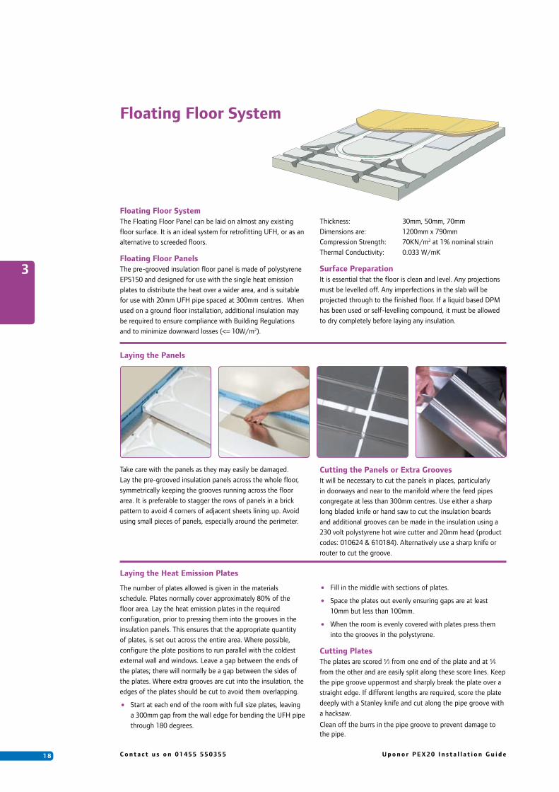
Floating Floor SystemThe Floating Floor Panel can be laid on almost any existing floor surface. It is an ideal system for retrofitting UFH, or as an alternative to screeded floors.
Floating Floor PanelsThe pre-grooved insulation floor panel is made of polystyrene EPS150 and designed for use with the single heat emission plates to distribute the heat over a wider area, and is suitable for use with 20mm UFH pipe spaced at 300mm centres. When used on a ground floor installation, additional insulation may be required to ensure compliance with Building Regulations and to minimize downward losses (<= 10W/m2).
Thickness: 30mm, 50mm, 70mm Dimensions are: 1200mm x 790mm Compression Strength: 70KN/m2 at 1% nominal strainThermal Conductivity: 0.033 W/mK
Surface PreparationIt is essential that the floor is clean and level. Any projections must be levelled off. Any imperfections in the slab will be projected through to the finished floor. If a liquid based DPM has been used or self-levelling compound, it must be allowed to dry completely before laying any insulation.
Take care with the panels as they may easily be damaged. Lay the pre-grooved insulation panels across the whole floor, symmetrically keeping the grooves running across the floor area. It is preferable to stagger the rows of panels in a brick pattern to avoid 4 corners of adjacent sheets lining up. Avoid using small pieces of panels, especially around the perimeter.
Cutting the Panels or Extra GroovesIt will be necessary to cut the panels in places, particularly in doorways and near to the manifold where the feed pipes congregate at less than 300mm centres. Use either a sharp long bladed knife or hand saw to cut the insulation boards and additional grooves can be made in the insulation using a 230 volt polystyrene hot wire cutter and 20mm head (product codes: 010624 & 610184). Alternatively use a sharp knife or router to cut the groove.
3
Laying the Panels
Floating Floor System
Laying the Heat Emission Plates
The number of plates allowed is given in the materials schedule. Plates normally cover approximately 80% of the floor area. Lay the heat emission plates in the required configuration, prior to pressing them into the grooves in the insulation panels. This ensures that the appropriate quantity of plates, is set out across the entire area. Where possible, configure the plate positions to run parallel with the coldest external wall and windows. Leave a gap between the ends of the plates; there will normally be a gap between the sides of the plates. Where extra grooves are cut into the insulation, the edges of the plates should be cut to avoid them overlapping.
• Start at each end of the room with full size plates, leaving a 300mm gap from the wall edge for bending the UFH pipe through 180 degrees.
• Fill in the middle with sections of plates.
• Space the plates out evenly ensuring gaps are at least 10mm but less than 100mm.
• When the room is evenly covered with plates press them into the grooves in the polystyrene.
Cutting PlatesThe plates are scored ¹⁄3 from one end of the plate and at ¹⁄6 from the other and are easily split along these score lines. Keep the pipe groove uppermost and sharply break the plate over a straight edge. If different lengths are required, score the plate deeply with a Stanley knife and cut along the pipe groove with a hacksaw.
Clean off the burrs in the pipe groove to prevent damage to the pipe.
1 9U p o n o r P E X 2 0 I n s t a l l a t i o n G u i d e C o n t a c t u s o n 0 1 4 5 5 5 5 0 3 5 5
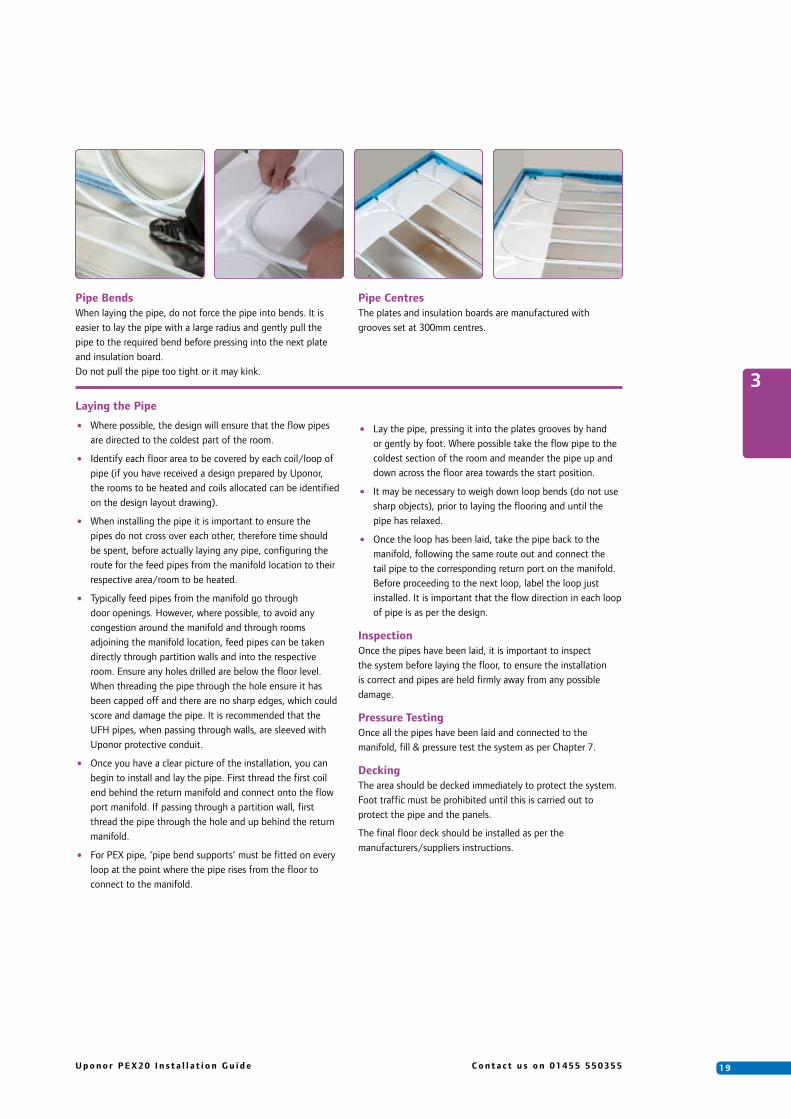
Pipe BendsWhen laying the pipe, do not force the pipe into bends. It is easier to lay the pipe with a large radius and gently pull the pipe to the required bend before pressing into the next plate and insulation board. Do not pull the pipe too tight or it may kink.
Pipe CentresThe plates and insulation boards are manufactured with grooves set at 300mm centres.
3
• Where possible, the design will ensure that the flow pipes are directed to the coldest part of the room.
• Identify each floor area to be covered by each coil/loop of pipe (if you have received a design prepared by Uponor, the rooms to be heated and coils allocated can be identified on the design layout drawing).
• When installing the pipe it is important to ensure the pipes do not cross over each other, therefore time should be spent, before actually laying any pipe, configuring the route for the feed pipes from the manifold location to their respective area/room to be heated.
• Typically feed pipes from the manifold go through door openings. However, where possible, to avoid any congestion around the manifold and through rooms adjoining the manifold location, feed pipes can be taken directly through partition walls and into the respective room. Ensure any holes drilled are below the floor level. When threading the pipe through the hole ensure it has been capped off and there are no sharp edges, which could score and damage the pipe. It is recommended that the UFH pipes, when passing through walls, are sleeved with Uponor protective conduit.
• Once you have a clear picture of the installation, you can begin to install and lay the pipe. First thread the first coil end behind the return manifold and connect onto the flow port manifold. If passing through a partition wall, first thread the pipe through the hole and up behind the return manifold.
• For PEX pipe, ‘pipe bend supports’ must be fitted on every loop at the point where the pipe rises from the floor to connect to the manifold.
• Lay the pipe, pressing it into the plates grooves by hand or gently by foot. Where possible take the flow pipe to the coldest section of the room and meander the pipe up and down across the floor area towards the start position.
• It may be necessary to weigh down loop bends (do not use sharp objects), prior to laying the flooring and until the pipe has relaxed.
• Once the loop has been laid, take the pipe back to the manifold, following the same route out and connect the tail pipe to the corresponding return port on the manifold. Before proceeding to the next loop, label the loop just installed. It is important that the flow direction in each loop of pipe is as per the design.
InspectionOnce the pipes have been laid, it is important to inspect the system before laying the floor, to ensure the installation is correct and pipes are held firmly away from any possible damage.
Pressure TestingOnce all the pipes have been laid and connected to the manifold, fill & pressure test the system as per Chapter 7.
DeckingThe area should be decked immediately to protect the system. Foot traffic must be prohibited until this is carried out to protect the pipe and the panels.
The final floor deck should be installed as per the manufacturers/suppliers instructions.
Laying the Pipe

2 0 C o n t a c t u s o n 0 1 4 5 5 5 5 0 3 5 5 U p o n o r P E X 2 0 I n s t a l l a t i o n G u i d e
Push 12
4
4. Water Temperature Control
Water Temperature Control for Underfloor Heating in one room
The Uponor Push 12 has been specially developed for small areas of underfloor heating in one room. It is designed to connect directly to the existing radiator system pipe work and supply one underfloor heating loop.
The Uponor Push 12 is designed to ensure that both the room temperature and the flow water temperature are maintained at a set level. A thermostatic valve (TRV) controls the water temperature in the underfloor heating system to suit the requirements of the room. An additional thermostatic valve is built into the pump housing to limit the temperature of the flow water in the underfloor heating loop. This special design ensures that both the room temperature and the flow water temperature are maintained at a set level.
For a solid screed floor construction the design heat output is maximum 100 W/m2. The underfloor heating pipes are normally installed at 300mm centres, and so one 60m loop of Uponor PEX 20 x 2mm underfloor heating pipe will cover a floor area of approximately 15m2.
The Push 12 is designed to be fitted directly to an existing radiator circuit. The water temperature in the underfloor heating loop must be lower than the water temperature in the radiator system. In order to obtain the required heat output, the flow in the underfloor heating loop must be greater than that in the radiator circuit. The Uponor Push 12 increases the water flow and controls the water temperature in the underfloor heating loop.
InstallationThe Uponor Push 12 has been specially developed for use in conjunction with an existing radiator heating system, connecting directly to the existing pipework. It is supplied factory set for a two pipe system, but can easily be adapted to a single pipe system (see Figs. 1 and 2), and the setting on the thermostatic valve adjusted accordingly.
The air temperature sensor is supplied with a 2m capillary tube. The sensor should be fitted to the nearest available wall, preferably an inner wall. The thermostatic valve to which the sensor is connected (via the capillary tube), will automatically control the flow from the radiator circuit to ensure that the correct water temperature is supplied to the underfloor heating loops, achieving the desired room temperature.
The adjustable thermostatic valve has a temperature setting range of between 6°C and 27°C. To achieve a room temperature of approximately 20°C, the thermostatic valve should be set to number 3. An additional thermostatic valve is built into the pump housing in order to limit the water temperature in the underfloor heating loops. The balancing valve on the pump housing is used to set the pressure and flow in the underfloor heating loops.
If required, the thermostatic head and air sensor can be replaced with a 230 volt thermal actuator, which can then be controlled via a room or programmable thermostat.
In order to minimise any noise in the Uponor Push 12, the maximum recommended pressure drop in the valve should not exceed 30 kPa. Uponor recommend that, if the underfloor heating loop is to be installed in a bedroom or a bathroom, then the Push 12 should be fitted outside the room itself.
MaintenanceThe Uponor Push 12 generally requires no maintenance. However, as a precaution it should be regularly inspected for leaks, and checked to ensure that the pump is not making any unusual noise. Excessive noise may be caused by air getting into the heating system. This can usually be resolved by turning the pump off, allowing the system to settle and then purging it of air through the air bleed valve (numbered 4 in Figs. 1 and 2), before re-starting it. Should the pump be inoperative for any length of time, check that the impeller on the pump is able to rotate freely by starting and stopping the pump several times. During the summer months, the pump should be inspected and run at least once a week, in order to ensure that it remains in good working order.

2 1U p o n o r P E X 2 0 I n s t a l l a t i o n G u i d e C o n t a c t u s o n 0 1 4 5 5 5 5 0 3 5 5
4
1 Thermostatic valve2 Air temperature sensor with capillary tube3 Circulation pump for underfloor heating loop4 Air bleed valve
The Uponor Push 12 is designed primarily to provide underfloor heating in a single room and room temperature control is provided only in the room in which the air temperature sensor is mounted. The Uponor Push 12 is further influenced by any central air temperature thermostat or programmer fitted to the radiator circuit which directly controls the operation of the boiler or heat source. The underfloor heating will only be “ON” when the radiator system is “ON”. The thermostat or programmer may need to be adjusted to suit the underfloor heating system.
Underfloor heating in individual rooms made easy
5 Flow connection to underfloor heating loop6 Return connection from underfloor heating loop7 Return to radiator heating system8 Flow from radiator heating system9 Balancing valve for regulation of pressure drop in underfloor heating system
3 4 9
5 6
1
7 8
2
3 4 9
5 6
1
7 8
2
Fig 1. Basic diagram for a single pipe system Fig 2. Basic diagram for a two pipe system
Item Code Push 12 080386 230V Thermal Actuator 803865
Product Code
Fig 3. Pump diagram
Fig 4 . Distance from wall to centre pipe 43 mm. Total build depth 78mm. Radiator circuit connection Ø 15 mm. Underfloor heating loops Uponor-PEX 20 x 2 mm pipe as standard.
Fig 5. Electrical connection 1 x 230 V AC, 50 Hz, 0.11 A.
Fig 6 . The LED indicates that the pump is connected to the electrical supply.

2 2 C o n t a c t u s o n 0 1 4 5 5 5 5 0 3 5 5 U p o n o r P E X 2 0 I n s t a l l a t i o n G u i d e
UNIset Installation
• For future reference record the UNIset name and batch number found on the box label.
UNIset Product Name:
• In a majority of cases and as recommended, these instructions have been written assuming the UFH manifold has been installed prior to the UNIset, and a directly coupled manifold and UNIset arrangement is required.
• All fittings, except the pump unions, telescopic compression nut, brackets and manifold connectors, are supplied sealed with liquid thread sealing compound.
• When tightening fittings to the UNIset always ensure the liquid sealed components are sufficiently restrained to prevent rotation and breaking of thread seals.
• Identify all components and ensure adequate space for mounting the UNIset is provided.
• For directly coupled manifold and UNIset arrangements insert the anti-vibration rubber spacers (4 off) between the manifold brackets and the wall, see figure 1 and 2.
Uponor UNIset MINI, MIDI and MAXI
Introduction
• The pre-assembled UNIset is designed for control of both water temperature and flow rates in secondary UFH circuits. All sets are robust and engineered for use in new and old domestic and commercial applications. The range of three set sizes gives the UNIset flexibility to match individual project duties without compromising performance.
• Standard UNIsets are supplied for left-hand primary connections. The MINI set can be handed by removing the brackets and rotating the pump through 180O. Right-hand MIDI and MAXI sets are available subject to special order.
• Please read these instructions completely before commencing installation, this will reduce both initial setup and commissioning time.
UNIset Contents
• Circulation Pump
• Telescopic return pipe for variable manifold centres
• 1” Ball valves with butterfly handles
• Brass interconnecting piping
• Mounting brackets
• Rubber lined pipe clips
• 1” Brass manifold ball valve connection set
• Manifold bracket spacer set
• DUOmix TMV with electro-thermal actuator (MINI set only)
• 3-port rotary shoe valve (MIDI and MAXI sets only)
Note: Water Temperature Controller and valve actuator for the MIDI and MAXI sets are sold separately.
Installation Instructions
UNIset MINI UNIset MIDI UNIset MAXI
UNIset Product Name:
....................................................................................
UNIset Batch Number:
....................................................................................
Spacers
4
Fig 1.
Fig 2.

2 3U p o n o r P E X 2 0 I n s t a l l a t i o n G u i d e C o n t a c t u s o n 0 1 4 5 5 5 5 0 3 5 5
• The UNIset is supplied ready for installation with a manifold header vertical pitch of 145mm. To adjust the UNIset vertical header pitch, to either 200mm or 225mm prior to mounting, follow the procedure below:-
i) Ensure the telescopic compression nut is loose.
ii) Unscrew the top bracket fixings adjacent to the pump.
iii) Slide the pump assembly away from the bottom header to the desired position and reinstate the bracket screws.
iv) Leave the telescopic compression nut loose until the UNIset is fixed in its final wall position.
• Apply thread sealant to the 1” BSPM end of the manifold connection sets and fit to the manifold ball valves.
• Remove the plastic dust caps from the manifold connections of the UNIset and offer the UNIset assembly up to the manifold and mark the bracket fixing locations.
• Lay the UNIset aside and prepare the wall fixings, (not supplied), then fix the UNIset to the wall.
• Insert the fibre washers between the manifold connection set flanges and the UNIset and tighten the swivel nuts and telescopic compression nut.
• Ensure the pump shaft is horizontal by loosening and retightening the pump unions. See pump installation instructions for further details.
UNIset MINI, DUOmix Actuator Installation
• Prior to fitting the valve actuator, the temperature setting of the TMV requires adjusting using a 10mm spanner.
• The fully down/clockwise rotated position corresponds to the minimum temperature setting of 35OC, and the fully up/anticlockwise rotated position corresponds to the maximum setting of 60OC.
• For intermediate temperature settings rotate the nut anticlockwise from the fully down position through an angle of 60O (one nut flat) for approximately every 4OC temperature rise required, see table below.
4
Rotation from fully closed (60O is one nut flat)
0O 60O 120O 180O 240O 300O 360O
35 39 43 48 52 56 60
Approx. mixed flow temp. OC
• Typically, the maximum water temperature setting for solid floors is 45OC and 60OC for timber suspended and floating floors.
• To install the actuator, position over the valve head and apply a downward pressure to compress the pin and hand tighten the actuator swivel nut. The primary hot port is now in the closed position until the actuator is energised, as shown by the actuator indicator.
UNIset MIDI and MAXI, Motorized Valve Actuator Installation
• The MIDI and MAXI sets are designed for use with the UP36 Water Temperature Controller (product code UP36) and 66M valve actuator (product code Z66M00); both are ordered and supplied separately.
• Set the valve shaft in the mid-position of the scale plate, number 5, and remove the handle without changing the position of the valve spindle.
• Place the white sleeve on the spindle.
• Screw either of the actuator anti-rotation studs in the lower right hand corner of the valve cover plate.
• Install the actuator to the valve in the horizontal position with the red indicator uppermost, and secure with the central screw.
• Fit the scale sticker to the knob with the larger blue indicator to the right-hand side. For special order right-hand feed UNIsets, the larger blue indicator should be fitted to the left-hand side. Finally press the cover plate on the knob.
• Should manual operation of the valve be required simply press and twist the knob in the desired direction.
2 4 C o n t a c t u s o n 0 1 4 5 5 5 5 0 3 5 5 U p o n o r P E X 2 0 I n s t a l l a t i o n G u i d e
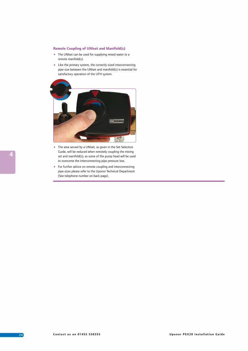
Remote Coupling of UNIset and Manifold(s)
• The UNIset can be used for supplying mixed water to a remote manifold(s).
• Like the primary system, the correctly sized interconnecting pipe size between the UNIset and manifold(s) is essential for satisfactory operation of the UFH system.
• The area served by a UNIset, as given in the Set Selection Guide, will be reduced when remotely coupling the mixing set and manifold(s), as some of the pump head will be used to overcome the interconnecting pipe pressure loss.
• For further advice on remote coupling and interconnecting pipe sizes please refer to the Uponor Technical Department (See telephone number on back page).
4

2 5U p o n o r P E X 2 0 I n s t a l l a t i o n G u i d e C o n t a c t u s o n 0 1 4 5 5 5 5 0 3 5 5
The UP36 controller and accessories offer set-point water temperature control to a hydronic underfloor heating system with the added benefit of built-in weather compensation control. The controller uses a floating action, mixing valve and actuator to vary and maintain the supply water temperature.
As standard, the unit is supplied with two strap-on pipe sensors and an outside temperature sensor. For full installation instructions please refer to the ‘Data Brochure’ enclosed with the UP36 controller and the associated mechanical and electrical schematics in Chapter 6.
The mixing valve and actuator are supplied separately, either as part of the Uniset assembly, or loose and selected upon the controlled floor area and output requirement. If Uponor has designed the system the valve size will have been specified, alternatively you can contact our technical office for valve sizing tables.
Set-Point Temperature ControlUnder set-point control the UP36 controller will maintain the MIX TARGET temperature (design water temperature) set by the installer in the ADJUST menu. A MIX TARGET setting is available for both the occupied and unoccupied modes. An outdoor sensor is not required during this mode of operation.
Weather CompensationOnce configured, the controller will automatically vary the supply water temperature depending upon the outside temperature. In other words, the unit takes into account that heat losses from the building will vary depending upon the weather and adjust accordingly, producing a much more economical and efficient system. An outdoor sensor is required during this mode of operation.
UP36 Weather Compensator
Remote SensorsThe UP36 is supplied with ‘mix supply’ and ‘boiler’ pipe sensors along with an outside sensor as standard. The mix supply pipe sensor should be positioned on the underfloor heating flow pipe, after the mixing valve and pump.
The boiler pipe sensor is generally positioned on the boiler primary flow, before the mixing valve and providing that the UP36 is the only control operating the boiler, will control the boiler at the lowest possible supply temperature that is sufficient to satisfy the mix target. Should you wish to protect the boiler from cold return water temperatures, the sensor must be located on the boiler primary return and the ‘boiler min’ setting set to the minimum return temperature required.
The outside sensor must be fitted when weather compensation control is required and is to be located on an external wall, preferably north facing at high level, uninfluenced from any heat source such as the sun.
An indoor sensor (item no OJ076) may be used to provide indoor feedback. With the indoor sensor connected, the UP36 is able to sense the actual room temperature, which will fine-tune the supply water temperature in the mixing system to maintain room temperature. To adjust the room temperature, use the ROOM OCC or ROOM UNOCC settings in the ADJUST menu. If used along with multiple room thermostats the placement of the indoor sensor is essential, in so much as it best represents the average air temperature of the zones. The indoor sensor cannot be used with set-point control.
User InterfaceThe UP36 uses a Liquid Crystal Display (LCD) as the method of supplying information. The LCD is used to set up and monitor the operation of your system. The UP36 has three push buttons (Item,,,) for selecting, viewing and adjusting settings.
Increasing Water Temperature
Terminal Unit
Indoor Design
Design Supply
Outdoor Design
Dec
reas
ing
Out
door
Tem
pera
ture
4

2 6 C o n t a c t u s o n 0 1 4 5 5 5 5 0 3 5 5 U p o n o r P E X 2 0 I n s t a l l a t i o n G u i d e
ItemThe abbreviated name of the selected item will be displayed in the item field of the display. To view the next available item, press and release the Item button. Once you have reached the last available item, pressing and releasing the Item button will return the display to the first item.
AdjustTo make an adjustment to a setting in the controller, press and hold simultaneously for 1 second the Item, , and buttons. This will take you from the VIEW menu and the display will then show the word ADJUST in the top right corner. Then select the desired item using the Item button. Finally use the and/or button to make the adjustment.
To exit the ADJUST menu, either select the ESC item and press the or button, or leave the adjustment buttons alone for 20 seconds.
When the Item button is pressed and held in the VIEW menu, the display will scroll through all the adjust items in both access levels.
Additional information can be gained by observing the status field and pointers of the LCD. The status field will indicate which of the control outputs are currently active. Most symbols in the status field are only visable when the VIEW menu is selected.
DIP SwitchesThe DIP switch settings on the control are very important and should be set to the appropriate settings prior to making any adjustments to the control. Located behind the fascia panel in the right hand corner.
Advanced/Installer – Used to select which items are available to be viewed and/or adjusted.
Boiler Sensor – Selects the installation location for the boiler sensor.
Boiler Enable – The middle DIP switch (not labelled), is only operational if the ‘boiler sensor’ switch is set to return (see section C of the UP36 data brochure).
When the UP36 is powered up, please allow at least five seconds for the controller to enter into the normal operating mode before any adjustment can be made.
Programming Set-Point ControlSet the DIP switch to ‘Installer’ mode.
Press and hold simultaneously for 1 second the Item, and buttons and work through table below. - Set-Point Control
Programming Weather Compensation Set the DIP switch to Installer mode.
Press and hold simultaneously for 1 second the Item, and buttons.
Press Item button until you reach ‘OUTDR DSGN’ then press button until you reach -3OC.
Leave for 20 seconds for controller to register this value and return to the VIEW menu.
Again press and hold simultaneously for 1 second the Item, and buttons and work through table overleaf. - Weather Compensation Control
Advanced settings can easily be changed within the controller. Please refer to Data Brochure supplied with each UP36 unit for further information.
Display Item Description Range
Mixed design water set-point temperature during the 16 to 93OC occupied period. (Factory Setting 45OC) Typical Settings: Screed: 40 to 45OCMIX TARGET OCC Adjust as necessary and then press Item Timber: 50 to 55OC
Mixed design water set-point temperature during 16 to 93OC the unoccupied period. (Factory Setting 30OC) Typical Settings: Screed: 30OCMIX TARGET UNOCC Adjust as necessary and then press Item Timber: 40OC
The outdoor air design temperature used in the heat loss calculation for the heating system. (Factory Setting OFF) -53 to 0OC, OFF
OUTDR DSGN Leave as OFF and press Item
This item exits the ADJUST menu by pressing either the or button.
ESC
Set Point Control
4

2 7U p o n o r P E X 2 0 I n s t a l l a t i o n G u i d e C o n t a c t u s o n 0 1 4 5 5 5 5 0 3 5 5
Weather Compensation Control
4
Display Item Description Range
The outdoor air design temperature used in the heat loss calculation for the heating system. (Factory Setting OFF) -53 to 0OC, OFF
OUTDR DSGN Should be set to -3OC (UK & Ireland), then press Item
The type of floor constructions that are being used in the Screed: 1 heating system. (Factory Setting = 1) (High Mass Radiant)
Leave at 1 for solid floors or change to 2 for plated & Timber: 2TERMINAL UNIT Unifoil systems, then press Item (Low Mass Radiant)
This item exits the ADJUST menu by pressing either the or button.
Or leave for 20 seconds and display will exit ADJUSTESC and return to VIEW menu.
The desired room temperature during the occupied period. Requires Indoor Sensor connected to UP36. (Factory Setting 21OC) 2 to 38OC
ROOM OCC Adjust as necessary and then press Item
The desired room temperature during the unoccupied period. Requires Indoor Sensor and Timeswitch connected to UP36. (Factory Setting 18OC). 2 to 38OC
ROOM UNOCC Adjust as necessary and then press Item
TerminalUnit
MotorSpeed
Open Close MixDemand
Item
OUTDR DSGN DIFF VIEW ADJUST
MINMAXBOIL TARGET
MIXROOM WWSDINDR UNOCC
OFOC
ButtonsSelects Menus, Items andadjusts settings
Status FieldDisplays the current display of the control’sinputs, outputs and opperation
Menu FieldDisplays the current menu
Number FieldDisplays the current valueof the selected item
Item FieldDisplays the obbreviatedname of the selected item
User Interface Display
Symbol Description
OCC
UNOCC
OC
PumpDisplays when the mixing systempump is in operation.
BurnerDisplays when the boiler relay is turned on.
Occupied ScheduleDisplays when the control is inoccupied (Day) mode.
Unoccupied ScheduleDisplays when the control is inunoccupied (Night) mode.
OCDisplays the unit of measure of all the temperatures displayed in the control.
PointerDisplays the control operation asindicated by the text.
Advanced
Installer
Return
Supply
Boiler Sensor
DIP Switches

2 8 C o n t a c t u s o n 0 1 4 5 5 5 5 0 3 5 5 U p o n o r P E X 2 0 I n s t a l l a t i o n G u i d e
5
5. Room Controls
With underfloor heating (UFH), the basic principles of domestic thermostatic control remain the same. The floor of a room can be considered to be a large low surface temperature radiator, but instead of a self-regulating thermostatic radiator valve to provide room temperature control, a room thermostat is used to open and close a loop(s) on the UFH manifold. Alternatively, a single room sensor or programmable room thermostat can be used to control the UFH as a single zone.
Uponor recommends that all UFH systems are equipped with room temperature controls, to optimize operating efficiency of the heating system and provide for the flexibility of independent control to each room or heating zone.Uponor offers two options for individual room control:
1. Wireless radio controlled room thermostats.
2. 24 volt hard wired room thermostats.
Radio ControlRadio Control is Uponor’s preferred system for multi-zone installations. Radio thermostats can be located almost anywhere within the room and easily relocated if necessary. No planning or cost for routing cables to thermostats simplifies the electrical installation. As well as standard radio thermostats Uponor have developed a Premium version which more effectively measures thermal comfort. It incorporates both air and radiant temperature sensors and uses programmed algorithms to closely match the temperature felt by an occupant. The Radio Controller is a wiring centre with in-built relay logic that requires a 230 volt electrical supply and has an on board 230V/24V transformer for connection of 24V thermal actuators and Control Interface Unit. Each room or zone is equipped with a room thermostat, which signals to open/close the thermal actuators fitted to the respective heating loops on the manifold. 12 radio thermostats and 14 thermal actuators can be connected to each radio controller. While the Interface unit can manage up to 3 Controllers.
Radio Control Components
Room Controls
Controller Radio C-55The Controller Radio C-55 is designed for receiving and transforming of radio signals from a maximum of 12 radio thermostats. Like the C-35 unit, the C-55 unit has an in built 240-24V transformer, two relays and
can also control up to 14 x 24V actuators. Additional features of this unit include:
• Easy wireless installation of thermostats
• LED for each channel indication on/off/alarm
• Pump/Valve exercise function
• Connections to connect to an external timer unit (I-75, see next section)
• The majority of the wiring is possible without tools
• Lightweight unit
Inerface (I-75)The Interface(I-75) is designed to offer Night Set Back (NSB) of the internal room temperatures when used in conjunction with the Controller Radio (C-55). The modernly styled Interface has user
friendly directional navigation buttons situated below a back lit dot matrix screen which combines text and icons for simplified programming. The Night Set Back control increases the responsiveness of the system by ensuring the system is not allowed to cool below an acceptable level. The I-75 will ensure the system maintains a lower temperature during unoccupied times. Additional features and functions of the I-75 include:
• Holiday temperature
• Automatic summer/winter change choose able
• Set room names (kitchen, Living etc.)
• Five temperature setback programs
• Different access levels (Basic/Advanced/Installer)
• Max/min temperature limitations
• The interface can control up to three controllers
• Pump management settable to “Individual” or “Common”
Radio Thermostat with display T-75
• LCD display
• Push buttons for setting
• Sensor for operative temperature (measures radiant and convective heat)
• Easy wireless registration
• Available in silver or white
• Set point range 5-35OC
• Low battery indication
Radio Termostat T-55
• Dial for setting
• Sensor for air tempeerature
• LED indication for “Radio transmission” and “Low battery”
• Easy wirless registration
• Set point range 6-30OC, mark at 21OC
• Setting range can be limited mechanically by adjusting pins under the dial
Radio Termostat T-53
• Plain cover with internal setting
• Sensor for air tempeerature
• LED indication for “Radio transmission” and “Low battery”
• Easy wirless registration
• Set point range 6-30OC
• Terminals for connection of a room sensor
• Terminals for connection of a max/min floor sensor

5
Wired Control Uponor’s hard-wired control system, for multi-zone applications, incorporates a 230V/24V transformer housed within the Controller. This provides 24V power to the thermostats and thermal actuators. 3 room thermostat options are available including 2 with max/min limitation of floor temperature with a floor sensor connected. Each room or zone is equipped with a room thermostat, which opens and closes the thermal actuators fitted to the respective heating loops on the manifold. A 2 channel remote timer can be connected to allow programming of times for automatic setback of room temperatures.
Wired Control Components
Room Thermostat MountingThermostats are generally mounted approximately 1.5m above floor level, away from draughts, direct sunlight or any other direct heating outlet which could affect the reading. If a room is likely, presently or sometime in the future, to be used by a wheelchair user then thermostat mounting height should be lowered to between 1 to 1.2 metres. An advantage of radio thermostats is that they can easily be repositioned within the room to suit any change in room use.
Thermal ActuatorsThe on/off thermal actuators are fitted onto the UFH manifold and provide for automatic control of individual heating loops. They have an open and closed indicator window and take between 2–4 minutes to completely open.
Integration with Uponor Water Temperature ControlsThe Uponor electronic control systems can easily be integrated with the Uponor range of water temperature control sets, including the ‘UNIsets’ and UP36 Weather Compensator’. See electrical wiring details in Chapter 6.
Single Zone ControlSingle zone control options are dependent upon what water temperature control is selected. If using with a Push12, UNIset MINI or UP36 as set-point control, then a Programmable room thermostat will have been offered, providing both time and temperature control. See electrical wiring details in Chapter 6.
If the UP36 is to be used in weather compensator mode, then the Room Sensor (item no OJ076) will be required along with a single channel time switch. See electrical wiring details Option 3, Chapter 6.
For full installation and user instructions refer to the manuals enclosed with each item (additional copies available on request) and Chapter 6 of this guide.
Controller Wired C-35The Controller Wired C-35 is a relay/wiring centre that can control up to 14 x 24V actuators via a maximum of 12 hard wired 24V room thermostats. The unit has an in built 240-24V transformer
with two relays; one to send a demand signal to the heat source or water temperature control unit and one for a dedicated underfloor heating pump (if required). Additional features of this unit include:
• Pump/Valve exercise function
• Connections to connect to an external timer unit (I-35, see next section)
• The majority of the wiring is possible without tools
• Power LED
• Lightweight unit
Timer I-35The Timer (I-35) is deigned to offer Night Set Back (NSB) of the inter-nal room temperatures when used in conjunctions with the Controller Wired (C-35). The Night Set Back control increases the reponsiveness
of the system by ensuring the system is not allowed to cool below an acceptable level by maintaining a lower temperature during unoccupied times. The unit itself has navigation buttons situated around a large LCD making using and programming straight forward. Additional functions include:
• Holiday temperature
• Two temperature setback programs
• Optional automatic summer/winter time change
Wired Termostat for Floor Sensor T-37
• Dial for setting
• Sensor for air tempeerature
• LED for indication
• Terminal for floor sensor (internal setting for floor sensor)
• Set point range 6-30OC, mark at 21OC
• Setting range can be limited mechanically by adjusting pins under the dial
Wired Termostat T-35
• Dial for setting
• Sensor for air temperature
• LED for indication
• Set point range 6-30OC, mark at 21OC
• Setting range can be limited mechanically by adjusting pins under the dial
Public Wired Termostat T-33
• Plain cover
• Internal setting
• Sensor for air temperature
• Set point range 6-30OC, mark at 21OC
• Max/Min limitation with floor sensor
2 9U p o n o r P E X 2 0 I n s t a l l a t i o n G u i d e C o n t a c t u s o n 0 1 4 5 5 5 5 0 3 5 5

3 0 C o n t a c t u s o n 0 1 4 5 5 5 5 0 3 5 5 U p o n o r P E X 2 0 I n s t a l l a t i o n G u i d e
6. Mechanical and Electrical SchematicsThe following section of this guide is designed to show a heating engineer and an electrician how the system should be plumbed and wired.
The mechanical schematics are divided into two sections; Section 1 - Water Temperature Controls; Section 2 - Manifold Arrangement. When using the schematics, first find the Water Temperature Control arrangement applicable to your installation.
The options covered are as follows:
Option A - 3 Port Actuated Valve Arrangement with a UP36 controller
Option B - 4 Port Actuated Valve Arrangement with a UP36 controller
Option C - UNIset Mini Pre-assembled Arrangement with a 3 port thermostatic mixing valve
Option D - UNIset Midi/Maxi Pre-assembled Arrangement with a 3 port actuated mixing valve and a UP36 controller
Options A, B, C or D will then be plumbed to Option. 1
Option E - PUSH 12 Arrangement for Single Zone applications only.
Mechanical Schematics
The electrical schematics shown on the double pages are broken down into sections; Air Temperature Controls and Water Temperature Controls. First find the Air Temperature Control option that relates to your system from options A, B or C, then wire the switch live to the point shown on the relevant Water Temperature Control schematic.
The Air Temperature Control options are as follows:
Option - Uponor Control System - Wired
Option - Uponor Control System - Radio
Option - Single Zone Wiring Details
The Water Temperature Control options are as follows:
Option
Option
Option
A
B
C
1
2
3
- PUSH 12 (c/w 230V Thermal Actuator) Wiring Details
- UNIset MINI Wiring Details
- UP36 Controller Wiring
Electrical Schematics
6

3 1U p o n o r P E X 2 0 I n s t a l l a t i o n G u i d e C o n t a c t u s o n 0 1 4 5 5 5 5 0 3 5 5
6
How to wire an Uponor Control System (wired) to a UP36 Weather Compensation Controller.You will need to wire the relevant Air Temperature Control schematic drawing to the relevant Water Temperature Control schematic drawing. In this case the two relevant drawings are:
If we put the two drawings together the full schematic would be as follows:
Option C - Uponor Control System (wired)
Option 1 - UP36 Weather Compensation Controller
Electrical Example
Controller (C-35)
Optional Timer (I-35)
Do not apply power
SLC
230V SupplyFrom Fused
Spur
ELN
N
UP36 Water Temperature Controller
Uponor
PowerMix SysLDemand Pmp NN
Boiler ClsOpnPwrMix
IndrUnO Com Boil ComMix OutSw
321 654 87 109 11 12 13 15 1816 1714
Boiler Flow Sensor
Optional Room Sensor
Black***
Brown
Underfloor heating pump
Volt free output for boiler enable
DIP Switches
Switch Live
Mixed Flow Sensor
**Outside Sensor
andactuator
valve
shown withouttime control
Thermostat (T-37)
linked totime zone 2
Pubic Thermostat
(T-33)linked to
time zone 1
Basic Thermostat
(T-35)
time zone 2linked to
Basic Thermostat
(T-35)
01 02
a
b
01 02
03
03 04 05 06 07 08
04 05 06 07 08N L
Relay2Relay1
a
b6745
121112
Auto Link Auto Link Auto Link
09
10
Floor Sensor
E
LN
linked totime zone 1
Basic Thermostat
(T-35)

3 2 C o n t a c t u s o n 0 1 4 5 5 5 5 0 3 5 5 U p o n o r P E X 2 0 I n s t a l l a t i o n G u i d e
9
013
7
5
10
9
0
1
3
75
10
Boiler Return
Boiler Flow
Boiler Return
Boiler Flow
Water Temperature Controls
Water Temperature Controls Water Temperature Controls
Water Temperature Controls
3
01
109
75
BA 21
3
Notes,1) All items to be installed in accordance with manufacturers instructions and current best practices.2) The drawing excludes isolating & regulating valves for clarity.3) A bypass is recommended on the primary circuit.4) Valve actuator not shown on valve for clarity. Option BOption A
Option DOption C
3 Port Valve Plumbing Arrangement
Notes,1) All items to be installed in accordance with manufacturers instructions and current best practices.2) The drawing excludes isolating & regulating valves for clarity.3) A bypass is recommended on the primary circuit.4) Valve actuator not shown on valve for clarity.
1 2
3
BA
Underfloor Heating Pump
Isolation Valve
Isolation Valve
UNIset Mini TMV Actuator
The total height of the manifold and Uniset Mini is 350mm and the depth from the wall is 150mm.
Notes,1) A bypass is recommended on the primary circuit.2) The drawing excludes isolating & regulating valves for clarity.3) All items to be installed in accordance with manufacturers instructions and current best practices.4) If limited space is available the manifold and UNIset may be split and installed in different locations to save space.
UNIset MINI length - 400mm
UNIset MINI Pre-assembled Arrangement
Underfloor Heating Pump
Isolation Valve
Isolation Valve
Actuator
Notes,1) A bypass is recommended on the primary circuit.2) The drawing excludes isolating & regulating valves for clarity.3) All items to be installed in accordance with manufacturers instructions and current best practices.4) If limited space is available the manifold and UNIset may be split and installed in different locations to save space.
UP36 Controller
Outside Sensor
Optional Room Sensor
UNIset MIDI length - 400mm &UNIset MAXI length 460mm
UNIset MIDI/MAXI Pre-assembled Arrangement
Switch Live from air temperature controls
Boiler Flow SensorMixed Flow Sensor
Plumbed to option
1
Plumbed to option
1
Plumbed to option
1
Plumbed to option
1
4 Port Valve Plumbing Arrangement
Optional Extra
4 Port Valve and Actuator
Underfloor Heating Pump (by others)
3 Port Valve and ActuatorMixed Flow Sensor
UP36 Controller
Boiler Return
Boiler Flow Sensor
Outside Sensor
Optional Room Sensor
Boiler Flow
Two Port Motorised Zone Valve
Plumbed to option
Underfloor Heating Pump (by others)
Mixed Flow Sensor
UP36 Controller
Outside Sensor
Optional Room Sensor
Two Port Motorised Zone Valve
Boiler Return
Boiler Flow
Boiler Flow Sensor
Plumbed to option
Plumbed to option
Plumbed to option
Switch Live from air temperature controls
Switch Live from air temperature controls
Optional Extra
1
1
1
1
6

3 3U p o n o r P E X 2 0 I n s t a l l a t i o n G u i d e C o n t a c t u s o n 0 1 4 5 5 5 5 0 3 5 5
Single Zone Water Temperature Control - Push 12
WGF Manifold Arrangement
Option E
Option 1
PEX 20 WGF Manifold with Brackets, Ball Valves and End Caps
Notes,
1) The manifold is shown with thermal actuators. These will not be required when the underfloor heating is controlled as a single zone by one programmable thermostat or one UP36 + room sensor.
A motorised or actuated valve will also be required on the mixed flow to the manifold.
2) The manifolds are supplied as pairs and are available in 2,3 & 4 port manifolds. A combination of these manifolds should be joined to form a maximum of 12 loops.
3) The isolation valves, support brackets, end caps and thermal actuators are sold separate from the manifold. 90° Angled isolation valves are also available. See price list for details.
4) A bypass is recommeded on the primary circuit.
5) The drawing excludes pumps, heat source, isolating & regulating valves for clarity.
6) All items to be installed in accordance with manufacturer's instructions and current best practices.
Thermal Actuators
Support Brackets
End Cap
Isolation Valve
Programmable Thermostat
Single Zone Control with PUSH 12 and electrical room control option
Notes,
1) The PUSH 12 unit is supplied as standard with a non-electric thermostatic head and 2m capillary connection to a remote room sensor. The drawing above shows the PUSH 12 fitted with an electro-thermal
actuator for optional electrical room controls.
2) The UFH will be "ON" only when the radiator system is "ON" , i.e. controlled by the existing systems central heating programmer and room thermostat, unless a separate dedicated flow and return plus
2-port zone valve is installed to fire the boiler and boiler pump.
UFH flow & returnPrimary flow & return
Manifold Length
250mm
300mm
350mm
400mm
450mm
500mm
550mm
2 Loops
3 Loops
4 Loops
5 Loops
6 Loops
7 Loops
8 Loops
9 Loops 600mm
10 Loops 650mm
11 Loops 700mm
12 Loops 750mm
Dimensional Table
length - see table
6

3 4 C o n t a c t u s o n 0 1 4 5 5 5 5 0 3 5 5 U p o n o r P E X 2 0 I n s t a l l a t i o n G u i d e
Time zone 1
Time zone 2
No time control
This terminal must be connected from the controller to a thermostat if a thermostat is used for this channel
Controller (C-35) notes,The diagram below shows the Controller (C-35) linked to an optional Timer (I-35), five thermostats and ten 24V actuator heads. Only 8 of the 12 channels are shown for clarity. Each thermostat requires two core cable connection to the relevant thermostat terminals. The bottom connection must be made. The second wire should be connected to one of the three remaining terminals depending on whether the Timer (I-35) is being used and if so, which of the two time channels is being used. See Fig 1. A floor sensor can be linked to either the Thermostat (T-37) or the Public Thermostat (T-33). The Basic Thermostat (T-35) can not take the additional floor sensor. A combination of the different thermostats can be used together.
One of these three terminals must be connected from the Controller C-35 to a thermostat if a thermostat is used for this channel
Fig.1
Controller (C-35)
Optional Timer (I-35)
Wired Air Temperature Control
Option
Auto Link Auto Link Auto Link
shown withouttime control
Thermostat (T-37)Floor Sensor
E
L
N
time zone 2linked to
Basic Thermostat (T-35)
linked totime zone 1
Pubic Thermostat (T-33)
time zone 2linked to
Basic Thermostat (T-35)
linked totime zone 1
Basic Thermostat (T-35) To be wired to
option , or .1 2 3
Switch Live
Test
1 2 3
Controller (C-55)
Uponor Radio Thermostat (T-75)
Optional Interface (I-75)
Uponor Public Radio Thermostat (T-53)
Uponor Radio Thermostat (T-55)
Antenna
24V Thermal Actuators
a
b
+-
(available in white or silver)
123456789
101112
01 02 03 04 05 06 07 08 09 10 11 12
T
N
14 x
20 °c
24V
OK
RELAY1 RELAY2
Controller (C-55) notes,The Controller (C-55) is capable of controlling a maximum of 12 radio thermostats (a combination of the different types can be used) and 14 x 24V actuators. The Interface (I-75) shown is where all the system parameters can be viewed and adjusted. One Interface (I-75) has the ability of controlling up to three radio controllers.
Radio Air Temperature Control
Option
Data Stick
E
LN
To be wired to option , or .
Switch Live
N LRelay2Relay1
01 02
a
b
01 02
03
03 04 05 06 07 08
04 05 06 07 08
a
b6745
121112
09
10
B
A
L
6

3 5U p o n o r P E X 2 0 I n s t a l l a t i o n G u i d e C o n t a c t u s o n 0 1 4 5 5 5 5 0 3 5 5
6
1)
2)
3)
Notes Section
Water Temperature Controls Water Temperature Controls
Water Temperature Controls
Single Zone Air Temperature Control
3
UNIset MINI Actuator
NB
lack
Blu
e
N
Bla
ck
Volt free output for boiler enable
C
SL
Underfloor heating pump
UNIset MINI Wiring Details
Option
To be wired from option , or .A B C
OptionOption
Option
2
C
1
A B C
E
L
N
230V Supply
From Fused Spur
Single Zone Wiring Details
To be wired to option , or .1 2 3
(for setpoint control only)
Uponor accepts no liability arising from any information supplied which is given in good faith.
It is the responsibility of the client at all times to ensure that the designs are suitable for the particular purpose intended and that all wiring complies with the current IEE regulations.
Uponor reserves the right to alter specifications and operating parameters for all its underfloor heating systems at any time as part of its policy of continuous product development.
UP36 Weather Compensation Controller - Wiring Details
Programmable Thermostat
Switch Live
Switch Live
** The UP36 unit will operate as a constant water temperature controller if the Outside Sensor is not connected.
To be wired from option , or .A B C
* If a zone valve is used on the primary flow the brown L wire should be connected to terminal 5 at the UP36.
*** If a UNIset MIDI or MAXI is being used then two black wires numbered 4 & 5 on the mixing valves actuator lead are not to be used.
In order to avoid inductive pickup the mixing demand signal from the zone valve end switch or wiring/relay centre must be separate from the mains wiring. Failure to do so can result in a permanent UP36 demand which will permanently fire the UFH pump.
230V SupplyFrom Fused Spur
Underfloor heating pump
Supplied by others
Volt free output for boiler enable
ELN
N
PowerMix SysLDemand Pmp NN
321 654Boiler
87ClsOpnPwr
Mix
109 11IndrUnO Com Boil ComMix Out
Sw
12 13 15 1816 1714Do not apply power
Mixed Flow Sensor
Boiler Flow Sensor
Optional Room Sensor
**Outside Sensor
Black***
Brown
Switch Live From
*Zone valve
Brown
BlueN
UP36 Water Temperature Controller
Uponor
and actuatorMixing valve
Room Temperature Controls
(Optional Extra)
5
SLC
DIP Switches
Underfloor heating pump
N
N
PUSH 12's Thermal actuator
Blue
PUSH 12 wiring details when fitted with optional electro-thermal actuator
Switch live from room or programmable thermostat
N L
1N L 32 4
Optional Remote Time Switch(For setback control and mainly used in single zone applications)

3 6 C o n t a c t u s o n 0 1 4 5 5 5 5 0 3 5 5 U p o n o r P E X 2 0 I n s t a l l a t i o n G u i d e
7. Filling, Venting and Pressure Testing
There is an integral fill/vent valve on the manifold end caps, together with hose union connections; hose unions are supplied loose for on-site assembly.
Before starting, ensure that the end cap o-ring is not visible and that the fill port is uppermost, then:
• Ensure all electrical supplies are switched off.
• Remove the fill port cap and washer and connect the hose unions to both end caps.
• The integral valves in both end caps must be opened to fill the system; remove the valve cap and washer and use a 4mm Allen key to open the valves.
• Ensure the 1” BSP manifold flow and return valves on the manifold are CLOSED.
• Close all underfloor heating loop flow and return valves on the manifold.
• Fit a hose to the lower manifold hose union and run the other end of the hose to a suitable drain point.
• Connect a hose to the upper manifold hose union and connect the other end of the hose to a mains water tap.
• Individual loops need to be purged of air in turn. This is achieved filling the system one loop at a time by opening ONE pair of valves on the manifold, i.e. the first pair of manifold valves.
• Turn on the water tap. As the first loop fills with water, air will discharge through the hose to the drain. Once the air stops and there is a steady flow of water, shut the loop flow and return valves
• Repeat this procedure for all UFH loops on the manifold ensuring that the valves are closed on each loop after filling.
• Close the valves on the end caps and switch-off the mains water before disconnecting the hoses.
• If the UFH is being installed in the winter, anti-freeze can be added to the system water for protection against freezing.
7
Once the UFH pipes have been installed and filled, a hydraulic pressure test must be carried out on all loops prior to laying the screed or covering with the chosen floor coverings. A hydraulic pressure test kit is available from Uponor (Product Number 470262040).
• Close the 1” flow and return ball valves that are connected to the manifold.
• Ensure that all flow and return valves to the UFH loops are open.
• Fit a dial type pressure gauge to one of the manifold end caps. A 1/2” - 1/4” bush (Product Code: 010308) is required to fit a gauge to the end cap.
Filling the loops
• Connect a pressure test kit to the hose union and open the valve on this end cap. Ensure the other hose union valve is closed.
• Pump up the pressure in the manifold to 2 x the operating pressure (minimum 4 bar, maximum 6 bar) for at least 1 hour. After an initial slight drop in pressure as the pipes expand, there should be no further drop in pressure. Check the pressure gauge during this period to ensure that the pressure remains constant under this period.
• Decrease the pressure to the system working pressure (or a minimum of 2 bar). The system pressure will initially increase as pipes contract under the lower pressures and
Pressure Testing
3 7U p o n o r P E X 2 0 I n s t a l l a t i o n G u i d e C o n t a c t u s o n 0 1 4 5 5 5 5 0 3 5 5
7
Use of Corrosion InhibitorsUponor UFH pipes will not be:
• adversely affected by corrosion inhibitors normally used in central heating systems.
• adversely affected by accidental contact with linseed oil based sealing compounds, or soldering flux. However, the latter should not be used for making joints to the pipe.
• affected by soft, hard or aggressive potable water. The pipe will not be attacked by any constituents of concrete, screeds, mortars, and is fully resistant to attack from micro-organisms.
will then stabilise. If the pressure has not fallen below system working pressure after 1 hour the system is pressure tight.
• Uponor recommends that the system should remain under pressure whilst the floor is laid so that if any damage occurs to the pipe, the laying of the floor can be stopped and the damage repaired immediately. The floor should be laid immediately after the pressure test.
• Where there is a danger of freezing, suitable measures such as the use of glycol-based antifreeze should be taken, using the correct mixture of water and antifreeze solution. However, before start up, the glycol mixture should be thoroughly flushed out of the system and disposed of carefully.
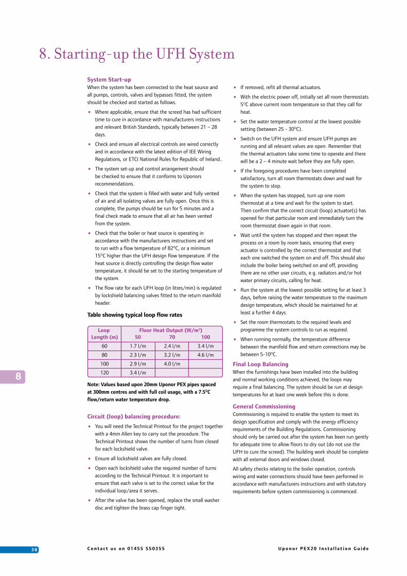
3 8 C o n t a c t u s o n 0 1 4 5 5 5 5 0 3 5 5 U p o n o r P E X 2 0 I n s t a l l a t i o n G u i d e
System Start-upWhen the system has been connected to the heat source and all pumps, controls, valves and bypasses fitted, the system should be checked and started as follows.
• Where applicable, ensure that the screed has had sufficient time to cure in accordance with manufacturers instructions and relevant British Standards, typically between 21 – 28 days.
• Check and ensure all electrical controls are wired correctly and in accordance with the latest edition of IEE Wiring Regulations, or ETCI National Rules for Republic of Ireland..
• The system set-up and control arrangement should be checked to ensure that it conforms to Uponors recommendations.
• Check that the system is filled with water and fully vented of air and all isolating valves are fully open. Once this is complete, the pumps should be run for 5 minutes and a final check made to ensure that all air has been vented from the system.
• Check that the boiler or heat source is operating in accordance with the manufacturers instructions and set to run with a flow temperature of 82OC, or a minimum 15OC higher than the UFH design flow temperature. If the heat source is directly controlling the design flow water temperature, it should be set to the starting temperature of the system.
• The flow rate for each UFH loop (in litres/min) is regulated by lockshield balancing valves fitted to the return manifold header.
Table showing typical loop flow rates
Circuit (loop) balancing procedure:
• You will need the Technical Printout for the project together with a 4mm Allen key to carry out the procedure. The Technical Printout shows the number of turns from closed for each lockshield valve.
• Ensure all lockshield valves are fully closed.
• Open each lockshield valve the required number of turns according to the Technical Printout. It is important to ensure that each valve is set to the correct value for the individual loop/area it serves.
• After the valve has been opened, replace the small washer disc and tighten the brass cap finger tight.
8. Starting-up the UFH System
• If removed, refit all thermal actuators.
• With the electric power off, initially set all room thermostats 5OC above current room temperature so that they call for heat.
• Set the water temperature control at the lowest possible setting (between 25 - 30OC).
• Switch on the UFH system and ensure UFH pumps are running and all relevant valves are open. Remember that the thermal actuators take some time to operate and there will be a 2 – 4 minute wait before they are fully open.
• If the foregoing procedures have been completed satisfactory, turn all room thermostats down and wait for the system to stop.
• When the system has stopped, turn up one room thermostat at a time and wait for the system to start. Then confirm that the correct circuit (loop) actuator(s) has opened for that particular room and immediately turn the room thermostat down again in that room.
• Wait until the system has stopped and then repeat the process on a room by room basis, ensuring that every actuator is controlled by the correct thermostat and that each one switched the system on and off. This should also include the boiler being switched on and off, providing there are no other user circuits, e.g. radiators and/or hot water primary circuits, calling for heat.
• Run the system at the lowest possible setting for at least 3 days, before raising the water temperature to the maximum design temperature, which should be maintained for at least a further 4 days.
• Set the room thermostats to the required levels and programme the system controls to run as required.
• When running normally, the temperature difference between the manifold flow and return connections may be between 5-10OC.
Final Loop BalancingWhen the furnishings have been installed into the building and normal working conditions achieved, the loops may require a final balancing. The system should be run at design temperatures for at least one week before this is done.
General CommissioningCommissioning is required to enable the system to meet its design specification and comply with the energy efficiency requirements of the Building Regulations. Commissioning should only be carried out after the system has been run gently for adequate time to allow floors to dry out (do not use the UFH to cure the screed). The building work should be complete with all external doors and windows closed.
All safety checks relating to the boiler operation, controls wiring and water connections should have been performed in accordance with manufacturers instructions and with statutory requirements before system commissioning is commenced.
Note: Values based upon 20mm Uponor PEX pipes spaced at 300mm centres and with full coil usage, with a 7.5OC flow/return water temperature drop.
Loop Floor Heat Output (W/m2) Length (m) 50 70 100
60 1.7 l/m 2.4 l/m 3.4 l/m
80 2.3 l/m 3.2 l/m 4.6 l/m
100 2.9 l/m 4.0 l/m
120 3.4 l/m8
3 9U p o n o r P E X 2 0 I n s t a l l a t i o n G u i d e C o n t a c t u s o n 0 1 4 5 5 5 5 0 3 5 5
8
To record surface temperatures correctly, a surface temperature electronic thermometer will be required and for best results thermal conducting paste should be used. Alternatively an infrared laser digital thermometer may be used for faster progress.
Care must be taken to ensure that floor surface temperatures are not exceeded.
Floor heating systems are typically designed to operate with a water flow temperature of approximately 45 – 50OC and a return temperature of 5 – 10OC less. There are occasions, mainly concerning floor coverings, when resistance to heat flow is so great that the water flow temperature must be increased in order to raise the floor surface temperature and achieve a better heat output.

4 0 C o n t a c t u s o n 0 1 4 5 5 5 5 0 3 5 5 U p o n o r P E X 2 0 I n s t a l l a t i o n G u i d e
System OperationOnce the system has been correctly balanced and commissioned, there is very little to concern the client with operating Uponor Underfloor Heating.
Time Clocks The UFH time clock is to be programmed to suit the building users requirements, depending upon their occupied and unoccupied periods during day and week; for example, when they go to work, or at what time they retire in the evening. It is normal for the UFH to be switched on approximately 2-3 hours before comfort conditions are required, especially true with screeded floors, due to the thermal lag associated with UFH. This also means the system can be switched-off approximately 2-3 hours before the end of the heating/occupied period.
The actual thermal lag is dependent upon the thermal mass of the floor structure; the thicker the screed the longer it will take to warm up and visa versa. Where the floor is of wooden structure, whose mass is typically one third of that of a screed floor, the response will be proportionately faster.
Air Thermostats These can be adjusted to provide optimum comfort control. Once comfort conditions have been met, further adjustment of the thermostat should not be necessary. When a room thermostat setting is altered to call for more heat, providing the new setting is within the systems capabilities, it may take a while before a higher temperature is felt in the room. The rate of heat build up under most conditions will be fairly constant. Turning the thermostat up to higher temperature levels than it is desired to achieve cannot increase this rate.
Unoccupied Set-Back (USB)USB is ideal for UFH because it reduces warm-up times between unoccupied and occupied heating periods throughout the day/week by lowering the desired room temperature by approximately 4OC during unoccupied periods. This ensures that the system response at the next occupied period is faster, because to heat the screed from cold each morning would be impractical (not applicable with wooden or lightweight flooring systems). However, a well insulated screed floor may only lose 1.5 – 2OC over an 8 hour period, therefore when switched to unoccupied set-back, the UFH system will effectively be off except in cold weather.
9. System Operation and Maintenance Water Temperature Controls The design water temperature should be set when the system is first commissioned and further adjustment is not usually necessary, except when the system is under performing (see chapter 10 trouble shooting). Adjustment is either directly on the water temperature control valves or on the UP36 controller. See specific installation instructions for further details.
Pump Speed Increasing the pump speed will increase the flow rate and slightly improve the system response time.
MaintenanceSince the heating loops are embedded and the pipe does not corrode, no maintenance is necessary for the pipes.When the UFH system is not in use, e.g. during the summer months, the system should be run for 2 – 3 minutes each week to exercise the pumps and valves (the UP36 controller has a built-in pump exercise programme). Pumps, valves and controls will require servicing as per the manufacturers instructions.
As for any plumbing joints, all joints at the manifold and flow and return should be checked regularly for any signs of leakage.
In older systems it is advisable to flush the system through with clean water to remove any sediment build-up.
9

4 1U p o n o r P E X 2 0 I n s t a l l a t i o n G u i d e C o n t a c t u s o n 0 1 4 5 5 5 5 0 3 5 5
10
10. Trouble ShootingAs described in earlier sections, the UFH system operation is relatively straightforward. Hot water from the primary heat source (boiler) is blended with the return water from the UFH secondary circuit at the mixing valve and distributed, via the secondary UFH pump, to the distribution manifold and into a series of UFH loops/circuits of pipe embedded within the floor. Normally, there is room temperature control, which will open and close a single or series of actuators mounted on the manifold, or prior to the manifold (single zone), depending upon the room requirement. If one or all thermostats are calling for heat, there is a boiler interlock switch to energise the boiler.
The majority of problems are usually simple installation problems, relating to wiring or plumbing, or design problems, with regard to the limitations of UFH and its suitability for the purpose intended.
In all cases where an electrical fault is reported it is always prudent to check the obvious before replacing components.
• Is there an electrical supply?
• Is it switched on?
• Are there any fuses that may have blown and need replacing?
• Are any components overloaded?
• Is everything wired correctly?
Under no circumstances replace a fuse with a higher rating than stated for that piece of equipment.
If the water arriving at the manifold (prior to entering the mixing valve) is either cold or below the design temperature, check:
• the boiler is firing
• the primary pump is fitted
• the primary pump is working
• the boiler is of adequate size
• the primary pipework is sufficiently sized
• the primary pumps are large enough
Further UFH Problems:If a loop or loops fail to warm, when other zones are
working correctly.General things to look for:
• Check that the corresponding manifold valves are open
• Check that there is a demand from the corresponding room thermostat and/or the thermal actuator is open on demand.
• There may be an air lock in the loop, which will require purging. Either shut down all other loops by closing the valves at the manifold or turn down all other room thermostats. This will concentrate all pump pressure to the problem loop and may shift the air blockage. If all else fails the loop can be flushed through with high-pressure water following the instructions detailed in Chapter 7 Filling, Venting and Pressure Testing.
If circulation is apparent but poor, it may be that the regulating control valve on the manifold requires adjustment.
If a room fails to warm.General things to look for:
• That the room thermostat fitted is calling for heat and that the valve has opened using the visual window on the actuator.
• That the room thermostat is connected to and communicating to the correct actuator(s).
• That the room thermostats are not operating in temperature set-back mode.
• That the flow temperature is correct as it enters the floor loops. Although typical design water temperatures are suggested throughout this guide, there is some element of a learning curve with UFH, as on some occasions the design water temperature may need to be raised after commissioning and once the system has been in operation during a heating season.
• That the primary flow and return connections are installed correctly and not crossed over at the UFH manifold.
• That the primary water temperature is not too low. This needs to be at least 15OC higher than the UFH system water temperature,
• Thermal resistance of floor covering is not too high, as this could reduce the floor heat output.
If the system is too noisy.General things to look for:
• There is no air in the system
• That all pipes are firmly clipped in place and that the manifold brackets are tight.
• That the UFH pump speed is not too high.
• That excessive pressure from another circulator in the system is not interfering (hence the importance of having a primary bypass).
If the running costs are high.General things to look for:
• That the UFH system is correctly electrically connected to the boiler to prevent short cycling and to ensure that the boiler is not running when it is not required.
• That the room temperatures and thermostat settings are not too high (typical comfort temperatures are 20OC in living quarters and 18OC in bedrooms).
• For any open windows or draughts. It is not unknown for windows to be opened in cold weather, as the internal comfort remains constant with thermostatic controls.
• That the boiler is running correctly. Has it been serviced and/or commissioned by an approved engineer.
• That the floor downward losses are high due to inadequate level of floor insulation.

4 2 C o n t a c t u s o n 0 1 4 5 5 5 5 0 3 5 5 U p o n o r P E X 2 0 I n s t a l l a t i o n G u i d e
The design water temperature is not metGeneral things to look for:
• Check all control valves are correctly installed in their correct orientation and that any remote sensors are installed and located in a suitable position.
• Check the temperature settings are as per design and adjust as necessary, depending on the water temperature control system used.
• Check the primary water temperature is not too low. This needs to be at least 15 degrees in excess of the UFH system water temperature.
The system is losing pressure.
General things to look for:
• If the system is losing pressure either during testing and/or after the system has been filled, but the flooring has not been laid, simple visual/manual checks around the manifold and along each loop of pipe should identify the problem area.
• If there are no clear visual signs, each loop/circuit may require a separate pressure test to identify the exact location.
• If the floor has been laid, identification of the fault can be traced through signs of a wet patch around the leak. Obviously to make the repair, the floor will have to be raised. In screed floors, excavate carefully in the centre of the wet patch.
• Any leaks on the manifold are generally due to the connection and any loose nuts and unions will require tightening.
Repairs.To make a repair to the pipe, follow the processes below.
For 20mm PEX (Wirsbo) pipeItems required:
• 2 x 22mm PEX inserts, item no. 020437
• 1 x 22mm x 22mm copper compression coupler (complete with 2 x nut & olive)
• Plastic pipe cutter
• Denso tape
Repairing the pipe:
• Isolate the damaged pipe loop at the manifold.
• Cut out the damaged section of pipe
• Prepare both ends of pipe using the pipe cutter
• Slide the compression nut and olive over each end of pipe, prior to inserting the insert into each end
• Offer both ends of pipe to the compression coupler and tighten both nuts
• Ideally, the joint will require an inspection chamber in case further maintenance is required. However, in practice this is often not practical, and the fitting is wrapped in suitable tape before burying in the screed (ensure approval with the building inspector is sought prior to doing this).
• Pressure test the system again before laying the floor covering.
10

4 34 3
UPONOR TRAINING ACADEMYThe Uponor Training Academy was established to offer a range of industry accepted courses, starting with a comprehensive installer training course and movingthrough to design and control oriented workshops, encompassing techniques associated with Uponor Plumbing and Underfloor Heating products. Bespoke workshops, tailored to suit individual needs are also available.
All courses are held at the purpose built facility close to Junction 20 of the M1, in the market town of Lutterworth. For Booking and Enquiries, please telephone:
Training Academy on 01455 203675Uponor Head Office on 01455 550355 oremail: [email protected]
UFH & PlumbingA two-day residential course at the purpose built facility in Lutterworth. The course is aimed at both new and experienced users of Uponor products.Day 1 gives a thorough understanding of applications of UFH and plumbing in the theory suite with Day 2 following with practical exercises in the hands-on practical suite.Price: £125 (plus vat) inclusive of meals, accommodation and course materials.Code: UTRAIN
Merchant CoursesA course which gives an overview of Uponor products and their applications. Mainly aimed at Merchants but can be specifically tailored to give a bespoke course for installers, or anyone who requires specific guidance in the application of UFH or Plumbing. Price on applicationCode: MTRAIN
This is a one day course aimed at experienced installers, architects, consultants and specifiers but will also benefit those with a knowledge of how UFH operates. This course will give a basic understanding of system requirements from a design point of view and an in depth knowledge of Uponor control systems, looking at new products which are now available.Price: £50 (plus vat) inclusive of lunch and course materials.Code: DTRAIN
Design Considerations & Controls
TRAINING
Plumbing CourseThe outline of this course is designed to enable installers to use Uponor multi layer and pex products, in place of other traditional materials such as copper, or conventional plastics, which will include piping primary pipework such as towel rails, cylinders and encompasses manifold plumbing - all mainly aimed at experienced plumbers, who would know how to connect up to a manifold.
There will be plenty of opportunity to practice these techniques in a safe environment in our purpose-built, practical area.Price: £63.83 (plus vat) inclusive of a buffet lunch and course materials.

UIG
-PEX
20-U
FH-M
ay 2
008
Copyright © Uponor (Uponor Housing Solutions Ltd.)Reproduction of any part of this publication for any purpose is not permitted without the prior written permission of Uponor Housing Solutions Ltd.
The information in this publication is correct at the time of going to press.
Uponor reserves the right to alter specifications and operating parameters for all its Underfloor Heating & Plumbing Systems at any time as part of its policy of continuous product development.
Uponor Housing Solutions LimitedSnapethorpe HouseRugby RoadLutterworthLeicestershire LE17 4HNT 01455 550355F 01455 550366E [email protected] www.uponorhousingsolutions.co.uk
Specification Centre, NorthPavillion 3, Buchanan Business ParkSteppsGlasgowG33 6HZT 0141 7795222
Specification Centre, SouthSpace HouseSatellite Business VillageCrawleyRH10 9NET 01293 655488
Uponor Housing SolutionsUnit 13, Seatown Business CampusSeatown Road, SwordsCo. Dublin, IrelandT 00 353 (0) 1895 7430F 00 353 (0) 1895 7434E [email protected] www.uponorhousingsolutions.ie