technical leaflet alezio - heating solutions miv/em : for additional heating via integrated...
TRANSCRIPT
Heating only :radiators or PCBT (low temperature underfloor heating)
Heat pumpair/water
Electricity(energy suppliedto the compressor)
Natural renewable energy free of charge
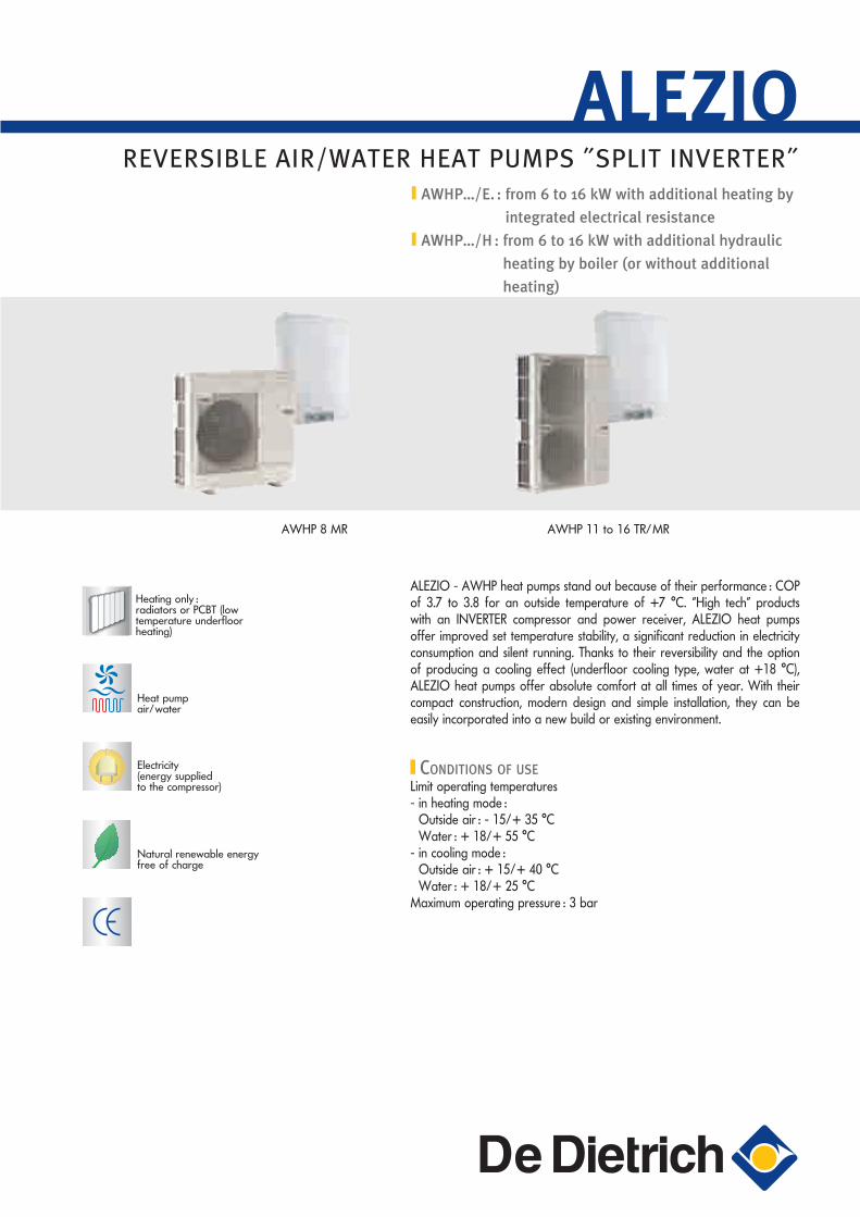
REVERSIBLE AIR/WATER HEAT PUMPS ˝SPLIT INVERTER˝
AWHP 8 MR AWHP 11 to 16 TR/MR
AWHP…/E. : from 6 to 16 kW with additional heating by
integrated electrical resistance
AWHP…/H : from 6 to 16 kW with additional hydraulic
heating by boiler (or without additional
heating)
ALEZIO
ALEZIO - AWHP heat pumps stand out because of their performance : COP of 3.7 to 3.8 for an outside temperature of +7 °C. “High tech” products with an INVERTER compressor and power receiver, ALEZIO heat pumps offer improved set temperature stability, a significant reduction in electricity consumption and silent running. Thanks to their reversibility and the option of producing a cooling effect (underfloor cooling type, water at +18 °C), ALEZIO heat pumps offer absolute comfort at all times of year. With their compact construction, modern design and simple installation, they can be easily incorporated into a new build or existing environment.
CONDITIONS OF USELimit operating temperatures- in heating mode :
Outside air : - 15/+ 35 °CWater : + 18/+ 55 °C
- in cooling mode :Outside air : + 15/+ 40 °CWater : + 18/+ 25 °C
Maximum operating pressure : 3 bar
90120 Alezio GB.indd 1 7/04/09 11:23:38

2
PRESENTATION OF ALEZIO - AWHP HEAT PUMPS
INTRODUCTION
ALEZIO heat pumps are of the “Split Inverter” type. Thanks to its integrated control system, the inverter system with “Power receiver” can be used to adapt the output of the heat pump perfectly to the needs of the installation. Thus, when needs are high in winter, the heat pump can provide its nominal output and, when needs are lower, the heat pump can provide only 30% of its nominal output.With the inverter system with “Power receiver”, electricity consumption is controlled and the COP improved.The connection between the outdoor unit and the indoor module is made by the refrigeration piping containing refrigerant.
INVERTER TECHNOLOGY WITH “POWER RECEIVER”This technology offers :- Optimal operation at low outside temperatures, up to -15 °C,
by accepting a high condensation temperature whilst preventing excessive overheating on compressor discharge.
- Maintenance of heating output with a high mass flow rate thanks to the use of a second expansion valve to control excessive cooling and to improve calorific recycling at lower evaporation temperatures.
- An increase in operating time in heating mode and a reduction of short cycles thanks to the “inverter” system which is used to adapt compressor output (from 30% to 100%) to the needs of the installation and control electricity consumption.
- Reduction of the defrosting time by a control system and a large surface area on the outdoor exchanger.
- A faster rise in temperature in the refrigerant fluid, preventing any risk of liquid surge at the compressor intake thanks to the “Power receiver”.
Heat pump
Back-up type Output Electrical by resistance Hydraulic
by boiler(or without back-up)
single phase three phase HeatingkW (1)
CoolingkW (2)
PAC
_Q00
33A
Reversible air/water heat pump for outside temperatures up to - 15 °C
AWHP 8 MR/EM — AWHP 8 MR/H 8,0 7,1
AWHP 11 MR/EM AWHP 11 TR/ET AWHP 11 MR/HAWHP 11 TR/H 11,2 10,0
AWHP 14 MR/EM AWHP 14 TR/ET AWHP 14 MR/HAWHP 14 TR/H 14,0 12,5
AWHP 16 MR/EM AWHP 16 TR/ET AWHP 16 MR/HAWHP 16 TR/H 16,0 14,0
(1) Water flue temp. : + 35 °C outside temp. : + 7 °C(2) Water flue temp. : + 18 °C, outside temp. : + 35 °C
THE VARIOUS MODELS AVAILABLE
Principle diagram of AWHP heat pumps
Double expansion and power receiverEvap
orato
r
Co
nd
enso
rRefrigerant pipingCompressor
Expansion valve
Outdoor unitIndoor module
4-way valve
Compressor Powerreceiver
Expansion A Expansion B
Outdoor unit Indoor module MIV
Heating output
Free energyWork of
the compressor
Additional quantity of heat recovered
"Additional"sub-cooling
Enthalpy (kj/kg)
Pressure P (MPa)
Refrigeration cycle
PAC
_F01
10A
PAC
_F01
11
90120 Alezio GB.indd 2 7/04/09 11:24:09
TECHNICAL CHARACTERISTICS OF THE AWHP
TECHNICAL SPECIFICATIONS
Conditions of use :Use limit temp. in heating mode :Water : + 18 °C/+55 °C, Outside air : - 15 °C/+ 35 °C
Use limit temp. in cooling mode :Water : +18 °C/+25 °C, Outside air : + 15 °C/+ 40 °C Max. operating pressure : 3 bar
R410AR410A
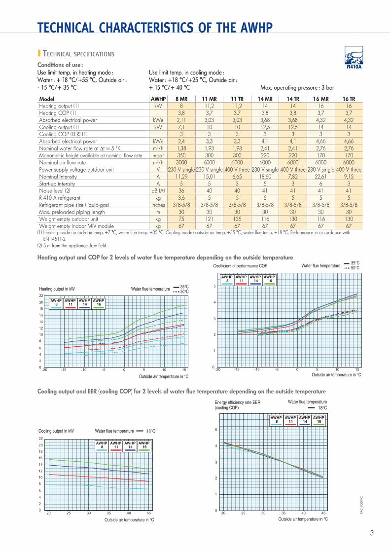
Model AWHP 8 MR 11 MR 11 TR 14 MR 14 TR 16 MR 16 TR Heating output (1) kW 8 11,2 11,2 14 14 16 16 Heating COP (1) 3,8 3,7 3,7 3,8 3,8 3,7 3,7 Absorbed electrical power kWe 2,11 3,03 3,03 3,68 3,68 4,32 4,32 Cooling output (1) kW 7,1 10 10 12,5 12,5 14 14 Cooling COP (EER) (1) 3 3 3 3 3 3 3 Absorbed electrical power kWe 2,4 3,3 3,3 4,1 4,1 4,66 4,66 Nominal water flow rate at ∆t = 5 °K m3/h 1,38 1,93 1,93 2,41 2,41 2,76 2,76 Manometric height available at nominal flow rate mbar 350 300 300 220 220 170 170 Nominal air flow rate m3/h 3000 6000 6000 6000 6000 6000 6000 Power supply voltage outdoor unit V 230 V single 230 V single 400 V three 230 V single 400 V three 230 V single 400 V three Nominal intensity A 11,29 15,01 6,65 18,60 7,82 22,61 9,15 Start-up intensity A 5 5 3 5 3 6 3 Noise level (2) dB (A) 36 40 40 41 41 41 41 R 410 A refrigerant kg 3,6 5 5 5 5 5 5 Refrigerant pipe size (liquid-gas) inches 3/8-5/8 3/8-5/8 3/8-5/8 3/8-5/8 3/8-5/8 3/8-5/8 3/8-5/8 Max. preloaded piping length m 30 30 30 30 30 30 30 Weight empty outdoor unit kg 75 121 135 116 130 116 130 Weight empty indoor MIV module kg 67 67 67 67 67 67 67
(1) Heating mode : outside air temp. +7 °C, water flue temp. +35 °C. Cooling mode : outside air temp. +35 °C, water flue temp. +18 °C. Performance in accordance with EN 14511-2.
(2) 5 m from the appliance, free field.
Heating output and COP for 2 levels of water flue temperature depending on the outside temperature
AWHP 11
AWHP 8
AWHP 16
AWHP 14
Water flue temperatureCoefficient of performance COP
Outside air temperature in °C
AWHP 14
AWHP 11
AWHP 8
AWHP 16
Heating output in kW Water flue temperature
Outside air temperature in °C
Cooling output and EER (cooling COP) for 2 levels of water flue temperature depending on the outside temperature
AWHP 14
AWHP 11
AWHP 8
AWHP 16
Outside air temperature in °C
Water flue temperatureEnergy efficiency rate EER(cooling COP)
AWHP 14
AWHP 11
AWHP 8
AWHP 16
Outside air temperature in °C
Cooling output in kW Water flue temperature
PAC
_F00
97C
3
90120 Alezio GB.indd 3 7/04/09 11:24:16
4
TECHNICAL CHARACTERISTICS OF THE AWHP
CHARACTERISTICS OF THE INDOOR MIV MODULE
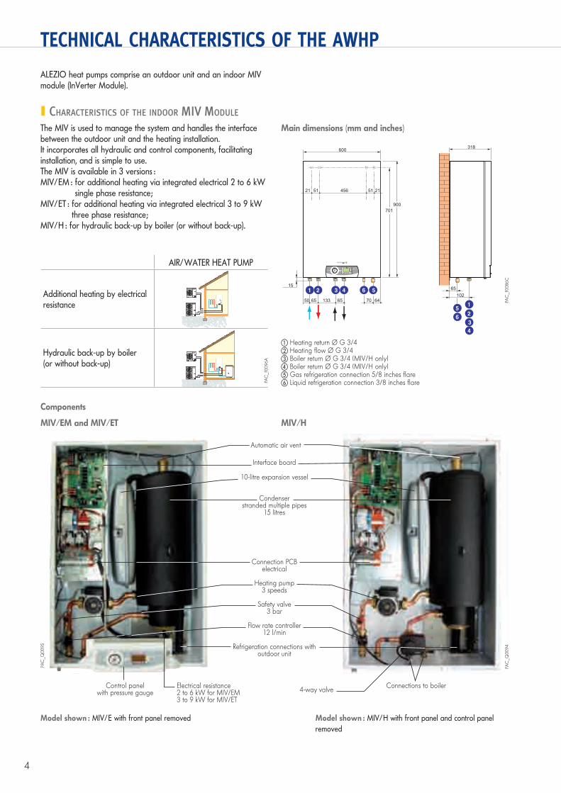
ALEZIO heat pumps comprise an outdoor unit and an indoor MIV module (InVerter Module).
The MIV is used to manage the system and handles the interface between the outdoor unit and the heating installation.It incorporates all hydraulic and control components, facilitating installation, and is simple to use.The MIV is available in 3 versions :MIV/EM : for additional heating via integrated electrical 2 to 6 kW
single phase resistance;MIV/ET : for additional heating via integrated electrical 3 to 9 kW
three phase resistance;MIV/H : for hydraulic back-up by boiler (or without back-up).
Main dimensions (mm and inches)
900
600 318
701
1 2
12
50
15
65 65 64133 70
65102
3 4
34
56
56
21 51 456 51 21
PAC
_F00
86C
� Heating return Ø G 3/4� Heating flow Ø G 3/4� Boiler return Ø G 3/4 (MIV/H only)� Boiler return Ø G 3/4 (MIV/H only)� Gas refrigeration connection 5/8 inches flare� Liquid refrigeration connection 3/8 inches flare
Components
MIV/EM and MIV/ET MIV/H
PAC
_Q00
95
PAC
_Q00
94
Interface board
10-litre expansion vessel
Condenserstranded multiple pipes
15 litres
Connection PCBelectrical
Heating pump3 speeds
Safety valve3 bar
Flow rate controller12 l/min
Refrigeration connections withoutdoor unit
Control panelwith pressure gauge
Connections to boiler
Model shown : MIV/E with front panel removed Model shown : MIV/H with front panel and control panel removed
Electrical resistance2 to 6 kW for MIV/EM3 to 9 kW for MIV/ET
4-way valve
5
5
PAC
_F00
96A
AIR/WATER HEAT PUMP
Additional heating by electrical resistance
Hydraulic back-up by boiler(or without back-up)
Automatic air vent
90120 Alezio GB.indd 4 7/04/09 11:24:16

5
TECHNICAL CHARACTERISTICS OF THE AWHP
TECHNICAL CHARACTERISTICS OF THE OUTDOOR UNIT
Main dimensions (mm and inches)AWHP 8 MR AWHP 11 to 16 MR/TR
1350
950
4556
53 28
19
23
417
175 600
330 370
30
443447
175
65 42
56
56
PAC
_F00
88
943
950
4556
53 28
19
23
417
175
330 370
30
443447
175
65 42
56
56
PAC
_F00
87
� Gas refrigeration connection 5/8 inches flare� Liquid refrigeration connection 3/8 inches flare
Components
AWHP 8 MR AWHP 11 to 16 MR/TR
PAC
_Q00
38
PAC
_Q00
37
Evaporator
Electronic PCB
4-way valvefor cycle inversion
Stop valve on therefrigeration connections with
outdoor unit
Power receiver
“Inverter” compressor
90120 Alezio GB.indd 5 7/04/09 11:24:32

6
THE CONTROL PANEL FITTED TO THE MIV/…
The control panel fitted to the MIV module on ALEZIO heat pumps incorporates an electronic control system used to adapt heating output to the actual needs of the installation according to the outside temperature (sensor provided). To do this, the control system activates modulation of the compressor (via the BUS cable connecting the outside unit to the MIV) and, where applicable, manages back-up by the boiler (MIV/H) or by the electrical resistance (MIV/E).
It is used to manage a single direct circuit, which can be a radiator circuit or a low temperature underfloor heating circuit. As for the production of domestic hot water, it will be handled by an electric or electrosolar water heater, or a water heater using another energy source. Moreover, this control system manages the reversibility of the heating in winter/cooling in summer, and incorporates a power cut-off function and a help mode. To operate in cooling mode, a wire-controlled or radio-controlled room temperature thermostat must be connected.
THE CONTROL PANEL
PAC
_Q00
93A
Pressure gauge
“MODE setting”key
“Temperature adjustment” key
“Forced back-upmode” key
Setting keyusing “+” or “-”
Display of the current MODE
Digital display unit
“Validation” key
CONTROL PANEL OPTIONS
Programmable wire room thermostat - Package AD 137Programmable wireless room thermostat - Package AD 200Non-programmable room thermostat - Package AD 140
Package AD 140
Package AD 200
The programmable thermostats handle heating control and weekly programming according to various operating modes : “Automatic” according to the programme, “Permanent” at a set temperature or “Holidays”. The “wireless” version is delivered with a receiver box to be affixed to the wall close to the MIV.
The non-programmable thermostat can only be used to control the room temperature according to the instruction given.
8801
Q00
386
66Q
120A
Underfloor heating connection kit - Package HA 249This cable harness is inserted into the heating pump and includes wiring for connecting a safety thermostat for underfloor heating.85
31Q
047
90120 Alezio GB.indd 6 7/04/09 11:24:52
7
OPTIONAL EQUIPMENT FOR THE ALEZIO HEAT PUMP
PAC
_Q00
32
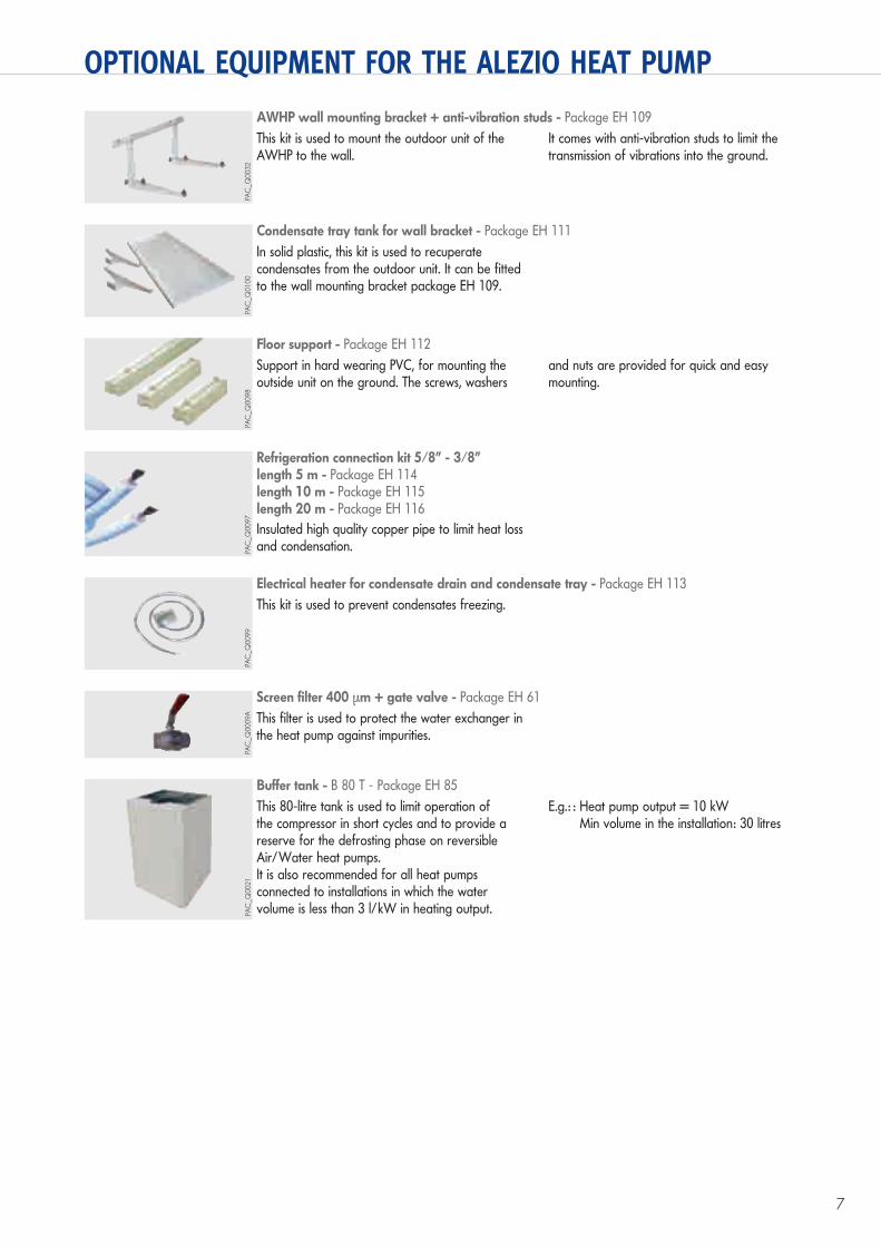
AWHP wall mounting bracket + anti-vibration studs - Package EH 109This kit is used to mount the outdoor unit of the AWHP to the wall.
It comes with anti-vibration studs to limit the transmission of vibrations into the ground.
PAC
_Q01
00
Condensate tray tank for wall bracket - Package EH 111In solid plastic, this kit is used to recuperate condensates from the outdoor unit. It can be fitted to the wall mounting bracket package EH 109.
PAC
_Q00
98
Floor support - Package EH 112Support in hard wearing PVC, for mounting the outside unit on the ground. The screws, washers
and nuts are provided for quick and easy mounting.
PAC
_Q00
97
Refrigeration connection kit 5/8” - 3/8”length 5 m - Package EH 114length 10 m - Package EH 115length 20 m - Package EH 116Insulated high quality copper pipe to limit heat loss and condensation.
PAC
_Q00
99
Electrical heater for condensate drain and condensate tray - Package EH 113This kit is used to prevent condensates freezing.
PAC
_Q00
09A
Screen filter 400 μm + gate valve - Package EH 61This filter is used to protect the water exchanger in the heat pump against impurities.
PAC
_Q00
21
Buffer tank - B 80 T - Package EH 85This 80-litre tank is used to limit operation of the compressor in short cycles and to provide a reserve for the defrosting phase on reversibleAir/Water heat pumps.It is also recommended for all heat pumps connected to installations in which the water volume is less than 3 l/kW in heating output.
E.g.: : Heat pump output = 10 kWMin volume in the installation: 30 litres
90120 Alezio GB.indd 7 7/04/09 11:25:05
8
SIZING A HEAT PUMP INSTALLATION
A heat pump must be accurately sized. Indeed, the choice of an appliance with too high an output considerably increases the cost of the installation without providing savings on consumption and the risk of short-cycle operation increases accordingly. The choice
of an appliance with too low an output also leads to excessive energy consumption caused by very long periods of operation of the appliance. It is therefore imperative in the first instance to make an accurate calculation of losses from the home.
PROCEDURE FOR CALCULATING LOSSES FROM AN INDIVIDUAL HOMEThe losses from an individual home canbe calculated using the procedure set out in the following formula :
D = G x V x ΔTwhere D = Losses in W
V = Habitable volume in m3
ΔT = Difference between the indoor temperature and the basis outdoor temperature
G = Coefficient based on the insulation of the building in W/m3 . °C
Example : for an individual home of 150 m2 (ceiling height 2,5 m) with basis outdoor temperature -7 °C constructed after 1990, the losses are :D = 1.1 x [(150 m2 x 2,5 m) x (20 °C - (-7 °C)] = 11 138 W, i.e. 11,14 kW
Note : this calculation method is given as a rough guide and in no way replaces a thermal survey. De Dietrich’s liability may in no event be invoked.
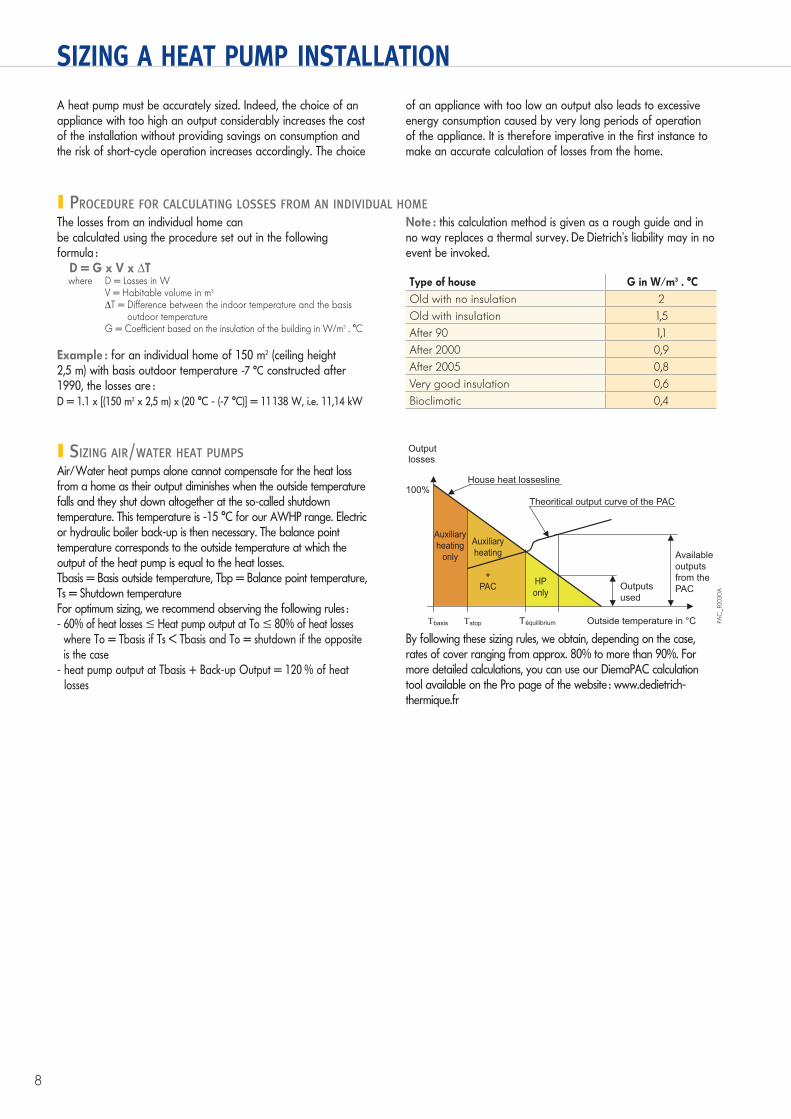
SIZING AIR/WATER HEAT PUMPSAir/Water heat pumps alone cannot compensate for the heat loss from a home as their output diminishes when the outside temperature falls and they shut down altogether at the so-called shutdown temperature. This temperature is -15 °C for our AWHP range. Electric or hydraulic boiler back-up is then necessary. The balance point temperature corresponds to the outside temperature at which the output of the heat pump is equal to the heat losses.Tbasis = Basis outside temperature, Tbp = Balance point temperature, Ts = Shutdown temperatureFor optimum sizing, we recommend observing the following rules :- 60% of heat losses � Heat pump output at To � 80% of heat losses
where To = Tbasis if Ts < Tbasis and To = shutdown if the opposite is the case
- heat pump output at Tbasis + Back-up Output = 120 % of heat losses
By following these sizing rules, we obtain, depending on the case, rates of cover ranging from approx. 80% to more than 90%. For more detailed calculations, you can use our DiemaPAC calculation tool available on the Pro page of the website : www.dedietrich-thermique.fr
Outputlosses
House heat lossesline100%
Auxiliary
heating
only
TT stopbasis Téquilibrium Outside temperature in °C
Theoritical output curve of the PAC
Auxiliary
heating
+
PACHP
onlyOutputs
used
Available
outputs
from the
PAC
PAC
_F00
30A
Type of house G in W/m3 . °COld with no insulation 2Old with insulation 1,5After 90 1,1After 2000 0,9After 2005 0,8Very good insulation 0,6Bioclimatic 0,4
90120 Alezio GB.indd 8 7/04/09 11:25:22

9
SIZING A HEAT PUMP INSTALLATION
TABLE FOR SELECTING THREE PHASE AWHP… TR MODELS FROM THE ALEZIO RANGE
TABLE FOR SELECTING SINGLE PHASE AWHP… MR MODELS FROM THE ALEZIO RANGE
+.. : minimum electrical or hydraulic back-up required in kW with hydraulic back-up only
Comments : - the losses must be precisely calculated without oversizing
coefficient +2, +4… corresponds to the minimum electrical or hydraulic back-up required in kW,
- the electrical back-up is 9 kW max. and requires a three phase power supply (6 kW max. in single phase),
- in installations with boiler back-up, it is possible to select a slightly undersized single phase heat pump instead of a three phase heat pump, on the understanding that it is tricky with
renovation projects to change a single phase into a three phase junction box,
- beneath the outside temperature from wich the heat pump stops (- 15 °C) only the additional back-ups provide heat.
Heat losses in kW 5 6 7 8 9 10 11 12 13 14 15 16 17 18 19 20
with
Tba
sis
in °C
0
8 MR
8 MR + 2
8 MR + 2
8 MR + 4
8 MR + 4
8 MR + 6
11 MR +411 MR + 6
14 MR + 414 MR + 6
16 MR + 6
16 MR + 6
16 MR + 9
16 MR + 9
16 MR + 12
16 MR + 12-1
8 MR + 6 11 MR + 6
14 MR + 6
-2
8 MR + 416 MR + 9
16 MR + 12
-3
14 MR + 6 16 MR + 6
-4
8 MR + 2
11 MR + 4
16 MR + 15
-5
11 MR + 6
-6
16 MR + 10
-7
16 MR + 9
-8
8 MR + 6
-9-10
16 MR + 15
-11
11 MR + 4-12
14 MR + 4-138 MR + 4-14 16 MR + 12-15
-16
8 MR + 6 8 MR + 9 8 MR + 9 8 MR + 12 11 MR + 12 11 MR + 12 14 MR + 15 14 MR + 15 14 MR + 18 16 MR + 18 16 MR + 18 16 MR + 21 16 MR + 21 16 MR + 24 16 MR + 24 16 MR + 24-17-18-19-20
Heat losses in kW 5 6 7 8 9 10 11 12 13 14 15 16 17 18 19 20
with
Tba
sis
in °C
0
-
-
-
11 TR +3
11 TR + 3
11 TR + 3
11 TR + 6
11 TR + 6
11 TR + 9
11 TR + 9
14 TR + 9
14 TR +9 16 TR + 9
16 TR + 9
16 TR + 12
16 TR + 12-1-2
11 TR
16 TR + 12
-3
11 TR + 6
-4
16 TR + 15
-5
11 TR + 3 11 TR + 916 TR + 9
-6
14 TR + 9 16 TR + 12
-7-8-9-10
16 TR + 15
-11
11 TR 11 TR + 6-12-13-14 16 TR + 12-15-16
11 TR + 9 11 TR + 9 11 TR + 12 11 TR + 12 11 TR + 12 11 TR + 15 11 TR + 15 11 TR + 18 14 TR + 18 14 TR + 18 16 TR + 21 16 TR + 21 16 TR + 24 16 TR + 24 16 TR + 24-17-18-19-20
90120 Alezio GB.indd 9 7/04/09 11:25:23

10
INFORMATION REQUIRED FOR INSTALLATION
INSTALLING ALEZIO HEAT PUMPS
- The outdoor units of ALEZIO heat pumps should be installed close to the house, on a terrace, on the façade or in a garden. They are designed to operate in the rain but can also be installed under cover as long as there is sufficient ventilation. There should be no obstacles to hinder the free circulation of air to the exchanger inlet and outlet (see installation diagrams below).
- The emplacement of the outdoor unit should be carefully chosen and protected from prevailing winds in order for it to be compatible with environmental requirements : integration into the site, noise level.
We particularly recommend :• Not placing the outdoor unit close to sleeping areas• Not placing it opposite a glazed wall• Avoiding proximity to a terraceMoreover, we recommend positioning the unit above the average depth of snowfall in the region in which it is installed.- It is necessary to provide clearance all around the appliance to
carry out connection, commissioning and maintenance operations.
➪ in red: AWHP 8MR➪ in blue: AWHP 11 to 16 MR/TR
IndoormoduleMIV
1000
950
150
600500 900
150330
1000
1000
1000100010001000
315
300
A
PAC
_F00
94
AWHP 8 MR 11 to 16 MR/TR
A (mm) 943 1350
100(150)200(300)
1000
Max. 500
500(1000)10(150)
100(200)
100(200)
200(300)
150(250)
150(250)
300(500)
1000(1500)
Max. 500
500(1000)
100(150)
PAC
_F00
95
AWHP 8 MR 11 MR/TR 14 MR/TR 16 MR/TR
L 50 75 75 75
- Maximum connection distance L between the MIV and the HEAT PUMP (in metres) MAXIMUM DISTANCES AND QUANTITY OF REFRIGERANT FLUID TO BE LOADED
- Preloaded quantity up to 30 mAdditional load of refrigerant fluid for a distance > 30 mfrom 31 to 40 m : 0,6 kgfrom 41 to 50 m : 1,2 kgfrom 51 to 60 m : 1,8 kgfrom 61 to 75 m : 2,4 kg
LB
2
1 C
Ø 5/8"
Ø 3/8"
PAC
_F00
98
B : 30 m maxC : number of elbows : 15 elbows max
� Outdoor unit� Indoor MIV module
Important : if the refrigeration link between the outdoor unit and the indoor module is less than 5 m long, noise pollution caused by the circulation of the refrigerant fluid may occur. If this is the case, fit a refrigeration link at least 5 m in length by making one or two horizontal connection loops in order to limit noise and oil traps.
MINIMUM INSTALLATION DISTANCES TO BE OBSERVED (mm)
90120 Alezio GB.indd 10 7/04/09 14:58:07
11
INFORMATION REQUIRED FOR INSTALLATION
REFRIGERATION CONNECTION
The commissioning of ALEZIO heat pumps includes operations on the refrigeration circuit.Appliances must be installed, commissioned, maintained and repaired by qualified, authorised personnel, pursuant to the requirements of prevailing directives, laws and regulations and in accordance with the codes of practice of the profession.Refrigeration connection :The refrigeration connection between the outdoor unit and the indoor module is made using “cold quality” copper piping. The polished, deoxidised, cleaned and dehydrated copper pipe is delivered in bars or coils and its ends are sealed. The copper pipe is insulated with a suitable form of insulation resistant to high temperatures in a thickness appropriate to its diameter.The connections of the refrigeration link to the outdoor unit and the indoor module are done by making dudgeons with flared fittings. If the pipes have to be lengthened, the brazes are done under nitrogen and with silver brazing rods.Diameters, height differences and the length of the refrigeration link between the outdoor unit and the indoor module must comply with the manufacturer’s recommendations.Watertightness inspection :When the refrigeration link has been completed, the role of the watertightness inspection is to ensure that there are no leaks and that it will withstand the various operating pressures to which it will be subjected.The watertightness inspection is done with dehydrated nitrogen. The test pressure is 5 bar to start with and is then increased by raising the nitrogen loading in increments of 5 bar until a total pressure of 35 bar is obtained for the R410A. The watertightness test is done using a “thousand particle” aerosol.
Evacuation :Evacuation is intended to eradicate air and humidity present in the refrigeration link.Air and humidity have an undesirable effect in the refrigeration circuit as the pressure increases in the system, the absorbed output increases, the efficiency of exchanges diminishes and corrosion of certain components is possible.Evacuation is done with a vacuum pump and a vacuum gauge to ensure the accuracy of the vacuum achieved.The duration of evacuation depends on the cleanliness of the circuit and may take several hours. After evacuation, precautions are taken to prevent the infiltration of humidity into the refrigeration circuit.Loading the refrigerant fluid :Loading a system consists in filling it with a quantity of refrigerant fluid giving the flow rate required for the correct operation of the heat pump.The outdoor units are preloaded in the factory and include a maximum distance for the refrigeration link. If the distance is greater than the maximum distance, it is necessary to add a further load.Annual watertightness inspection (in accordance with the local and national codes and regulations):This inspection is mandatory for all machines containing more than 3 kg of refrigerant fluid in accordance with prevailing regulations. The annual watertightness inspection is mandatory for all ALEZIO heat pumps.Commissioning and maintenance :In order to make the most of the performance of heat pumps and extend their useful life, De Dietrich proposes a commissioning and maintenance service for the ALEZIO range.
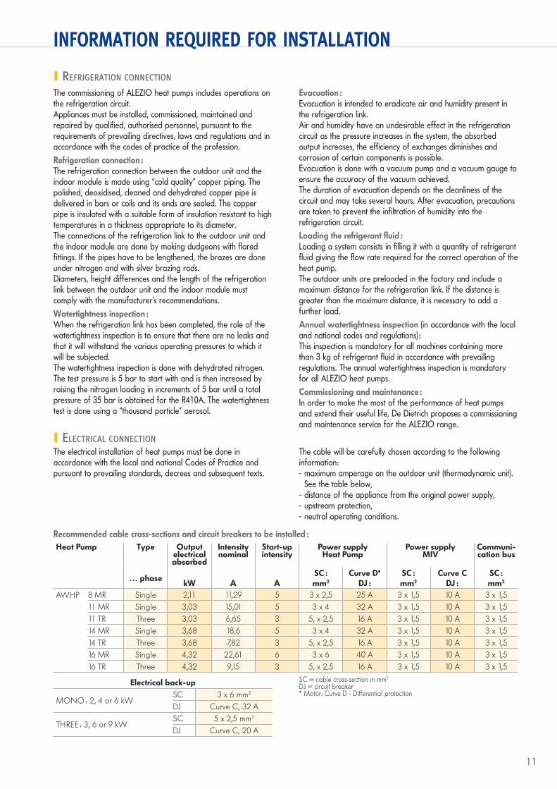
ELECTRICAL CONNECTIONThe electrical installation of heat pumps must be done in accordance with the local and national Codes of Practice and pursuant to prevailing standards, decrees and subsequent texts.
The cable will be carefully chosen according to the following information:- maximum amperage on the outdoor unit (thermodynamic unit).
See the table below,- distance of the appliance from the original power supply,- upstream protection,- neutral operating conditions.
Recommended cable cross-sections and circuit breakers to be installed :Heat Pump Type Output
electricalabsorbed
Intensitynominal
Start-up intensity
Power supplyHeat Pump
Power supplyMIV
Communi-cation bus
… phasekW A A
SC :mm2
Curve D*DJ :
SC :mm2
Curve CDJ :
SC :mm2
AWHP 8 MR Single 2,11 11,29 5 3 x 2,5 25 A 3 x 1,5 10 A 3 x 1,511 MR Single 3,03 15,01 5 3 x 4 32 A 3 x 1,5 10 A 3 x 1,511 TR Three 3,03 6,65 3 5, x 2,5 16 A 3 x 1,5 10 A 3 x 1,514 MR Single 3,68 18,6 5 3 x 4 32 A 3 x 1,5 10 A 3 x 1,514 TR Three 3,68 7,82 3 5, x 2,5 16 A 3 x 1,5 10 A 3 x 1,516 MR Single 4,32 22,61 6 3 x 6 40 A 3 x 1,5 10 A 3 x 1,516 TR Three 4,32 9,15 3 5, x 2,5 16 A 3 x 1,5 10 A 3 x 1,5
Electrical back-up
MONO : 2, 4 or 6 kWSC 3 x 6 mm2
DJ Curve C, 32 A
THREE : 3, 6 or 9 kWSC 5 x 2,5 mm2
DJ Curve C, 20 A
SC = cable cross-section in mm2
DJ = circuit breaker* Motor: Curve D - Differential protection
90120 Alezio GB.indd 11 7/04/09 11:25:27

12
INFORMATION REQUIRED FOR INSTALLATION
In order to protect the exchanger on the MIV, installation of the filter is mandatory. The “filter + gate valve” unit (package EH 61) can be delivered as optional.
Filters
Storage tankThe installation of a storage tank is recommended for installations in which the water volume is less than 3 l/kW in heating output on the heat pump (remember to factor in the 15 l in the MIV).It is intended :- on the one hand, to increase the water volume in an installation
in order to limit the short-cycle operation of the compressor. The greater the water volume, the lower the number of start-ups of the compressor and the longer its useful life.
- on the other hand, to guarantee an energy reserve for the defrosting phases.
HYDRAULIC CONNECTION
The indoor MIV module on ALEZIO heat pumps is fully equipped for the connection of a direct circuit (radiators or underfloor heating) : circulating pump, expansion vessel, heating safety valve, pressure gauge, air vent…
Characteristics of the GRUNDFOS UPS 25-70 heating pump fitted to the MIV :
0 0 0,5 1 1,5 2 2,5
1
2
3
4
5
6
7
8
Flow rate in m³/h
Pres
sure
in m
H2O
III
III
PAC
_F00
99
Note : As ALEZIO heat pumps are of the “SPLIT INVERTER” type with refrigeration link between the outdoor unit and the MIV module, it is not necessary to add glycol to the installation.
Important comments regarding :The various emitters :The water outlet temperature on heat pumps is limited : 55 °C max. for AWHP. It is therefore imperative that they operate on low temperature emitters, i.e. underfloor heating/cooling or radiators sized at low temperature. For the cooling mode, only underfloor heating with compatible flooring and floor covering is suitable. It is also necessary that the underfloor cooling flow temperatures be respected, depending on the geographical location, to prevent the phenomenon of condensation (between 18 °C and 22 °C).
Refrigerant fluids :R410A refrigerant fluid has properties suitable for heat pumps. It belongs to the family of HFCs (hydrofluorcarbons), composed of chemical molecules containing carbon, fluorine and hydrogen. It does not contain chlorine and therefore does not damage the ozone layer.
The cooling modeSo-called reversible heat pumps are used to produce a cooling effect in summer. A 4-way valve, called a cycle inverter valve, switches the cycle from heating mode to cooling mode.The compressor intake is thus linked to the indoor exchanger, which therefore becomes the evaporator. The compressor backflow is thus linked to the outdoor exchanger, which therefore becomes the condenser.Note : For Air/Water type heat pumps, this 4-way valve is also used for the defrosting phase on the evaporator.
In the case of an installation with underfloor heating/cooling, the refrigeration output is limited, but sufficient to keep the home pleasantly comfortable. On average, it allows the ambient temperature to be reduced by 3 to 4 °C. We therefore speak of cooling and not of air conditioning.
90120 Alezio GB.indd 12 7/04/09 11:25:27

13
EXAMPLES OF ALEZIO HEAT PUMP INSTALLATIONS
The examples presented below cannot cover the full range of installation scenarios that may be encountered. Their purpose is to draw the attention to the basic rules to be followed. A certain number of control and safety devices are shown but it is ultimately up to experts, consultant engineers and design
departments to take the final decision on the safety and control devices to be used in the boiler room according to its specificities. In all cases, it is necessary to abide by the codes of practice and prevailing regulations.
ALEZIO-AWHP heat pump with indoor MIV/E module, with electrical back-up- 1 direct “radiator” circuit- DHW production by electric water heater
θ
230V or 400V 50Hz
230V or 400V 50Hz
230V 50Hz
9
51
64
147
9
18
50
30 2928BUS
EH 61
AWHP/E
AD 137
230V
or 4
00V
50H
z
21
COR-EMAIL ..
52
7
16
11
3
5
MIV/E.
PAC
_F01
12C
230V or 400V 50Hz
129
131
112a
29 3028
81
109
230V50Hz
SET
Dietrisol B
<>
88
126
114
130
84
89
87
61
85
4
9θ
BESC...E
112b
230V or 400V 50Hz
230V 50Hz
9
44
147
9
18
50
BUS
EH 61
MIV/E.
AWHP/E
AD 137
230V
or 4
00V
50H
z
7
16
21
11
3
5
HA249
65
115
52
PAC
_F01
14E
ALEZIO-AWHP heat pump with indoor MIV/E module, with electrical back-up- 1 direct “underfloor heating ” circuit- DHW production by BESC... E electrosolar DHW tank,
90120 Alezio GB.indd 13 7/04/09 11:25:28

EXAMPLES OF ALEZIO HEAT PUMP INSTALLATIONS
ALEZIO-AWHP heat pump with indoor MIV/H module, with boiler back-up- 3-way reversal valve (117)- 1 direct “radiator” circuit- DHW production by the boiler
PAC
_F01
15D
230V 50Hz
230V 50Hz
BUS
MIV/H
AWHP/H Floor-standing, 2-service boiler
AD 137
EH 61
230V
or 4
00V
50H
z
51
21
9
9
9
117
HC 135
9
9
2727
9
26
26
9
7 3
4
27
9
32
302928
18
16
7
11
3
5151
50
64
9147
52
52
16
M
14
ALEZIO-AWHP heat pump with indoor MIV/H module, with boiler back-up- decoupling cylinder (35)- 1 direct “radiator” circuit- DHW production by the boiler
Key see page 16
PAC
_F01
25
230V 50Hz
230V 50Hz
BUS
MIV/H
AWHP/H Floor-standing 2-service boiler
AD 137
EH 61
230V
or 4
00V
50H
z
51
21
9
9
99
9
2727
9
26
26
9
7 3
4
27
9
32
302928
18
16
7
11
3
5151
50
64
9147
52
1613
35
7
8
� The flow rate of the boiler pump must be slightly higher (� 10 %) than the MIV pump.
90120 Alezio GB.indd 14 7/04/09 11:25:29

BUS
MIV/H
AWHP/H
AD 137
EH 61
230V
or
400V
50H
z
230V 50Hz
230V 50Hz
51
21
9
18
282930
16
7
11
3
5151
50
64
9147
52
CITADINE 2.24
B80TUsed as a
decoupling cylinder
11
EXAMPLES OF ALEZIO HEAT PUMP INSTALLATIONS
ALEZIO-AWHP heat pump with indoor MIV/H module, with boiler back-up- 1 direct “radiator” circuit- DHW production by the boiler
PAC
_F01
26
230V 50Hz
230V 50Hz
BUS
MIV/H
AWHP/H Floor-standing, 2-service boiler
230V
or 4
00V
50H
z
21
99
9
9
9
2727
910
2626
9
7 3
4
27
9
32
302928
16
7
11
3
5151
M
21
16
9
44
23
147
9
18
50
EH 61
HA249
65
115
52
AD 137
ALEZIO-AWHP heat pump with indoor MIV/H module, with boiler back-up- 1 direct “radiator” circuit- DHW production by the boiler- buffer tank B80T used as a decoupling cylinder
Key see page 16
PAC
_F01
27A
� For this type of installation it is necessary to have :- 1 floor-standing boiler with a DIEMATIC 3 control panel- 1 3-way mixing valve (10) controlled by the DIEMATIC 3- and in this configuration the parameter I TEL must be setted HEAT
15
90120 Alezio GB.indd 15 8/04/09 9:14:37

16
EXAMPLES OF ALEZIO HEAT PUMP INSTALLATIONS
DE DIETRICH THERMIQUES.A.S. with corporate capital of 22 487 610 d57, rue de la Gare - F - 67580 MertzwillerTel. + 33 3 88 80 27 00 - Fax + 33 3 88 80 27 99www.dedietrich-heating.com
ALEZIO-AWHP heat pump with indoor MIV/H module, with boiler back-up, B80T storage tank with bypass- 1 direct “radiator” circuit
PAC
_F01
16D
Key 3 3-bar safety valve 4 Pressure gauge 5 Flow rate controller 7 Automatic air vent 9 Isolation valve 10 3-way mixing valve 11 Heating pump 16 Expansion vessel 18 Filling device 21 Outside sensor 26 Load pump 27 Non-return valve 28 Domestic cold water inlet
29 Pressure reducer 30 Sealed safety device calibrated to
7 bar 32 DHW loop back pump 35 Decoupling cylinder 44 65 °C manual reset safety
thermostat for underfloor heating 50 Disconnector 51 Thermostatic valve 52 Differential valve 61 Thermometer 64 Direct heating circuit: radiators
65 Direct heating circuit:underfloor heating
81 Electrical resistance 84 Stop valve with unlockable non-
return valve 85 Primary solar circuit pump 87 Safety valve calibrated to 6 bar 89 Container for solar fluid 109 Thermostatic mixer tap 112a Solar collector sensor 112b Solar DHW tank sensor 114 Primary solar circuit filling and
draining circuit
115 Thermostatic distribution valve per zone
117 3-way reversal valve 126 Solar control system 129 Duo-pipes 130 Degasser with manual vent 131 Collector field 147 Filter + gate valves 151 Motorised 4-way valve
Important RecommendationsIn order to make the most of the performances of heat pumps for optimal comfort and to maximise their useful life, we recommend that you pay particular attention to their installation, commissioning and maintenance ; to do this, abide by the various instructions that come with the appliances. In addition, the De Dietrich catalogue offers a commissioning service for heat pumps ; we also strongly recommend that you take out a maintenance contract.
230V 50Hz
230V 50Hz
BUS
MIV/H
AWHP/H Floor-standing boiler, heating only
B80T
AD 137
230V
or 4
00V
50H
z
51
21
9
9 9
9
9
2726
7 3
4
18
16
7
11
3
5151
50
64
9
52
52
9
EH 61
9
147
16
04/0
9 –
3000
1973
2 –
347.
555.
559
Stra
sbou
rg C
ompa
nies
Reg
ister
– D
ocum
ent n
ot c
ontra
ctua
lly b
indi
ng -
Prin
ted
in F
ranc
e - O
TT Im
prim
eurs
673
10 W
asse
lonn
e - 9
0120
90120 Alezio GB.indd 16 7/04/09 11:50:31