h final student resource guide - youtube foundations.pdf · copyright © 2006 emc corporation. ......
TRANSCRIPT

Copyright © 2006 EMC Corporation. Do not Copy - All Rights Reserved.
NAS Foundations - 1
© 2006 EMC Corporation. All rights reserved.
NAS FoundationsNAS Foundations
Welcome to NAS Foundations.The AUDIO portion of this course is supplemental to the material and is not a replacement for the student notes accompanying this course.EMC recommends downloading the Student Resource Guide from the Supporting Materials tab, and reading the notes in their entirety.
Copyright © 2006 EMC Corporation. All rights reserved.These materials may not be copied without EMC's written consent.EMC believes the information in this publication is accurate as of its publication date. The information is subject to change without notice. THE INFORMATION IN THIS PUBLICATION IS PROVIDED “AS IS.” EMC CORPORATION MAKES NO REPRESENTATIONS OR WARRANTIES OF ANY KIND WITH RESPECT TO THE INFORMATION IN THIS PUBLICATION, AND SPECIFICALLY DISCLAIMS IMPLIED WARRANTIES OF MERCHANTABILITY OR FITNESS FOR A PARTICULAR PURPOSE.Use, copying, and distribution of any EMC software described in this publication requires an applicable software license.Celerra, CLARalert, CLARiiON, Connectrix, Dantz, Documentum, EMC, EMC2, HighRoad, Legato, Navisphere, PowerPath, ResourcePak, SnapView/IP, SRDF, Symmetrix, TimeFinder, VisualSAN, “where information lives” are registered trademarks. Access Logix, AutoAdvice, Automated Resource Manager, AutoSwap, AVALONidm, C-Clip, Celerra Replicator, Centera, CentraStar, CLARevent, CopyCross, CopyPoint, DatabaseXtender, Direct Matrix, Direct Matrix Architecture, EDM, E-Lab, EMC Automated Networked Storage, EMC ControlCenter, EMC Developers Program, EMC OnCourse, EMC Proven, EMC Snap, Enginuity, FarPoint, FLARE, GeoSpan, InfoMover, MirrorView, NetWin, OnAlert, OpenScale, Powerlink, PowerVolume, RepliCare, SafeLine, SAN Architect, SAN Copy, SAN Manager, SDMS, SnapSure, SnapView, StorageScope, SupportMate, SymmAPI, SymmEnabler, Symmetrix DMX, Universal Data Tone, VisualSRM are trademarks of EMC Corporation. All other trademarks used herein are the property of their respective owners.All other trademarks used herein are the property of their respective owners.

Copyright © 2006 EMC Corporation. Do not Copy - All Rights Reserved.
NAS Foundations - 2
© 2006 EMC Corporation. All rights reserved. NAS Foundations - 2
NAS FoundationsIdentify the concepts and value of Network Attached Storage
List environmental aspects of NAS
Identify the EMC NAS platforms and their differences
Identify and describe key Celerra software features
Identify and describe the Celerra Management software offerings
Identify and describe key Windows specific options with respect to EMC NAS environments
Identify and describe NAS Business Continuity and Replication options with respect to the various EMC NAS platforms
Identify and describe key NAS Backup and Recovery options
The objectives for this course are shown here. Please take a moment to read them.

Copyright © 2006 EMC Corporation. Do not Copy - All Rights Reserved.
NAS Foundations - 3
© 2006 EMC Corporation. All rights reserved. NAS Foundations - 3
Network Attached Storage
NAS OVERVIEW
We will start this course by defining Network Attached Storage (NAS).

Copyright © 2006 EMC Corporation. Do not Copy - All Rights Reserved.
NAS Foundations - 4
© 2006 EMC Corporation. All rights reserved. NAS Foundations - 4
What Is Network-Attached StorageBuilt on the concept of shared storage on a Local Area Network
Leverages the benefits of a network file server and network storage
Utilizes industry-standard network and file sharing protocols
Network
File Server + Network-attached storage = NAS
Client Application Application Application
Unix Client Unix ClientWindows Client
Network attached storage is not a new concept and, in fact, has been used by many business solutions. It is basically the concept that data can be centrally stored in a dedicated, built to purpose array, that has the sole function of presenting the data, for simultaneous access, to the clients over a network infrastructure without placing too much, if any, latency or accessibility limitations on data transfer.
NAS provides these features:1. Global shared access to storage independent of client locality.2. Access to data via Industry standard protocols, Common Internet File System (CIFS),
Network File System (NFS), Hypertext Transfer Protocol (HTTP) and File Transfer Protocol (FTP).
3. Can serve disparate clients simultaneously, e.g. Microsoft and UNIX.4. Predominantly Fast Ethernet and/or Gigabit Ethernet media for accessibility.5. Industry standard data transfer protocol support, TCP/IP.

Copyright © 2006 EMC Corporation. Do not Copy - All Rights Reserved.
NAS Foundations - 5
© 2006 EMC Corporation. All rights reserved. NAS Foundations - 5
Why NAS?
Highest availabilityScales for growthAvoids file replication
Increases flexibilityReduces complexityImproves securityCosts
Firewall
Web Servers
NAS
Internet
Data CenterSn
S2....
S1
InternalNetwork
Some of the main reasons for implementing NAS as a solution are shown on this slide. Please take a moment to read them.
By centralizing data storage, system complexity and administration overheads can be reduced. It can also reduce the complexity of business critical operations, such as backup, restore and disaster recovery.
Copyright © 2006 EMC Corporation. Do not Copy - All Rights Reserved.
NAS Foundations - 6
© 2006 EMC Corporation. All rights reserved. NAS Foundations - 6
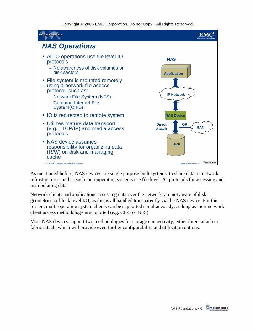
NAS OperationsAll IO operations use file level IO protocols– No awareness of disk volumes or
disk sectors
File system is mounted remotely using a network file access protocol, such as:– Network File System (NFS)– Common Internet File
System(CIFS)
IO is redirected to remote systemUtilizes mature data transport (e.g., TCP/IP) and media access protocolsNAS device assumes responsibility for organizing data (R/W) on disk and managing cache
Disk
IP Network
Application
NAS Device
NAS
SANORDirect
Attach
As mentioned before, NAS devices are single purpose built systems, to share data on network infrastructures, and as such their operating systems use file level I/O protocols for accessing and manipulating data.
Network clients and applications accessing data over the network, are not aware of disk geometries or block level I/O, as this is all handled transparently via the NAS device. For this reason, multi-operating system clients can be supported simultaneously, as long as their network client access methodology is supported (e.g. CIFS or NFS).
Most NAS devices support two methodologies for storage connectivity, either direct attach or fabric attach, which will provide even further configurability and utilization options.
Copyright © 2006 EMC Corporation. Do not Copy - All Rights Reserved.
NAS Foundations - 7
© 2006 EMC Corporation. All rights reserved. NAS Foundations - 7
NAS Architecture
Application
Remote I/O Request
Operating System
NFS/CIFS
TCP/IP Stack
Network Interface
File I/O to NAS
I/O Redirector
Network Interface
TCP/IP Stack
Network File Protocol Handler
NAS Operating System
To Storage
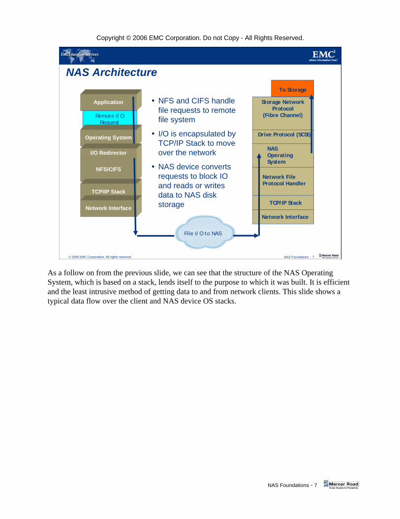
NFS and CIFS handle file requests to remote file system
I/O is encapsulated by TCP/IP Stack to move over the network
NAS device converts requests to block IO and reads or writes data to NAS disk storage
Drive Protocol (SCSI)
Storage Network Protocol
(Fibre Channel)
As a follow on from the previous slide, we can see that the structure of the NAS Operating System, which is based on a stack, lends itself to the purpose to which it was built. It is efficient and the least intrusive method of getting data to and from network clients. This slide shows a typical data flow over the client and NAS device OS stacks.
Copyright © 2006 EMC Corporation. Do not Copy - All Rights Reserved.
NAS Foundations - 8
© 2006 EMC Corporation. All rights reserved. NAS Foundations - 8
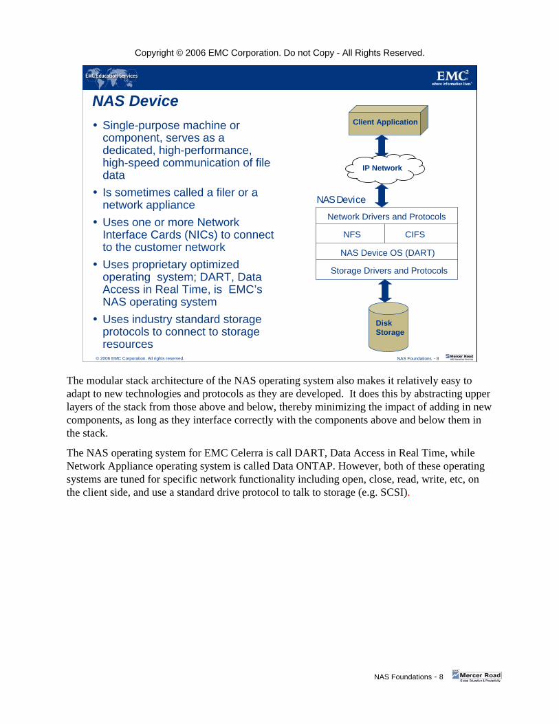
NAS DeviceSingle-purpose machine or component, serves as a dedicated, high-performance, high-speed communication of file dataIs sometimes called a filer or a network applianceUses one or more Network Interface Cards (NICs) to connect to the customer network Uses proprietary optimized operating system; DART, Data Access in Real Time, is EMC’s NAS operating systemUses industry standard storage protocols to connect to storage resources
Disk Storage
IP Network
Client Application
NAS Device
Network Drivers and Protocols
NFS CIFS
NAS Device OS (DART)
Storage Drivers and Protocols
The modular stack architecture of the NAS operating system also makes it relatively easy to adapt to new technologies and protocols as they are developed. It does this by abstracting upper layers of the stack from those above and below, thereby minimizing the impact of adding in new components, as long as they interface correctly with the components above and below them in the stack.
The NAS operating system for EMC Celerra is call DART, Data Access in Real Time, while Network Appliance operating system is called Data ONTAP. However, both of these operating systems are tuned for specific network functionality including open, close, read, write, etc, on the client side, and use a standard drive protocol to talk to storage (e.g. SCSI).
Copyright © 2006 EMC Corporation. Do not Copy - All Rights Reserved.
NAS Foundations - 9
© 2006 EMC Corporation. All rights reserved. NAS Foundations - 9
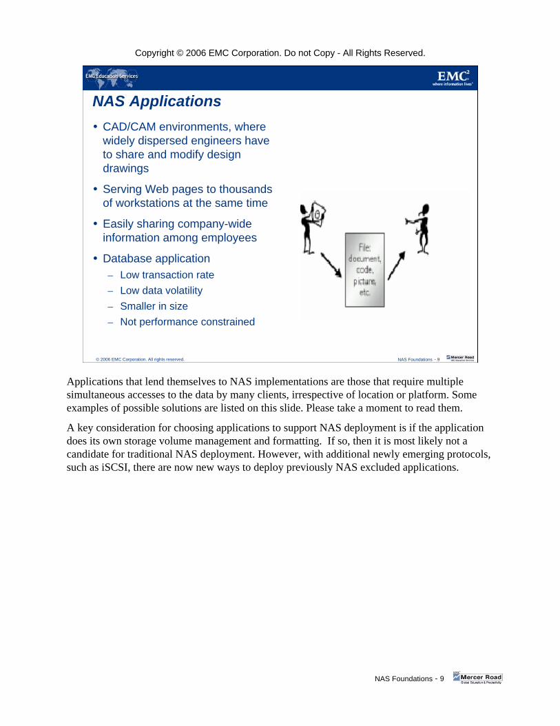
NAS ApplicationsCAD/CAM environments, where widely dispersed engineers have to share and modify design drawings
Serving Web pages to thousands of workstations at the same time
Easily sharing company-wide information among employees
Database application– Low transaction rate– Low data volatility– Smaller in size– Not performance constrained
Applications that lend themselves to NAS implementations are those that require multiple simultaneous accesses to the data by many clients, irrespective of location or platform. Some examples of possible solutions are listed on this slide. Please take a moment to read them.
A key consideration for choosing applications to support NAS deployment is if the application does its own storage volume management and formatting. If so, then it is most likely not a candidate for traditional NAS deployment. However, with additional newly emerging protocols, such as iSCSI, there are now new ways to deploy previously NAS excluded applications.

Copyright © 2006 EMC Corporation. Do not Copy - All Rights Reserved.
NAS Foundations - 10
© 2006 EMC Corporation. All rights reserved. NAS Foundations - 10
NAS Components and Networking Infrastructure
AN INTRODUCTION
In this next section we introduce some key components of NAS and networking infrastructures.

Copyright © 2006 EMC Corporation. Do not Copy - All Rights Reserved.
NAS Foundations - 11
© 2006 EMC Corporation. All rights reserved. NAS Foundations - 11
What is a Network?
Site 1
Site 2
LANPhysical MediaWAN
So what is a network? A common definition of a network is a collection of independent computers that communicate with one another, using a common protocol, over a shared network medium. The three most common acronyms to describe the distribution of computers in a network are: LAN, for Local Area Networks; WAN, for Wide Area Networks; and MAN, for Metropolitan Area Networks.

Copyright © 2006 EMC Corporation. Do not Copy - All Rights Reserved.
NAS Foundations - 12
© 2006 EMC Corporation. All rights reserved. NAS Foundations - 12
Physical Components
Network Interface Card (NIC)
Switches
Routers
NIC
NIC
NIC
NIC
Switch
Switch
Router
155.10.10.XX
155.10.20.XX
Some components that make up most network infrastructures today are the NIC (Network Interface Card), Switches, and Routers. The NIC provides host connectivity to the interconnect medium. Switches provide local segmentation of the interconnect medium and some level of management. Routers provide remote segmentation of the interconnect medium for widely dispersed networks, as well as another level of management to the infrastructure.
There are two basic ways that clients communicate over a network: User Datagram Protocol, (UDP), and Transmission Control Protocol, (TCP).
UDP is used in non-connection oriented networks, while TCP is used to manage the movement of data packets in connection oriented networks.
In a non-connection oriented communication model, the data is sent out to a recipient using a best effort approach, with no acknowledgement of the receipt of the data being sent back to the originator, by the recipient. Error correction and resend must be controlled by a higher layer application to ensure data integrity.
In a connection oriented model, all data packets sent by an originator are acknowledged by the recipient, and transmission errors/lost data packets are managed at the protocol layer.
NFS and CIFS both support UDP and TCP data transfer.
Copyright © 2006 EMC Corporation. Do not Copy - All Rights Reserved.
NAS Foundations - 13
© 2006 EMC Corporation. All rights reserved. NAS Foundations - 13
Network Protocols
Network transport Protocols
Network filesystem Protocols
NIC
NIC
NIC
NIC
Switch
Switch
Router
155.10.10.XX
155.10.20.XX
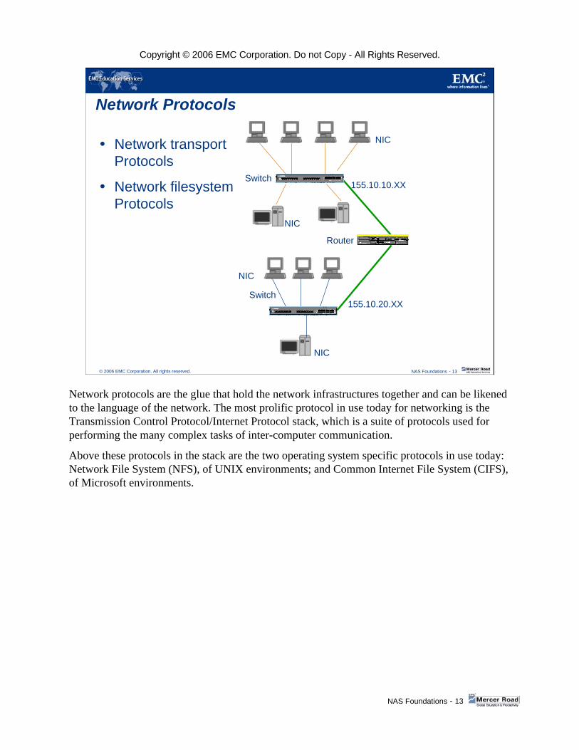
Network protocols are the glue that hold the network infrastructures together and can be likened to the language of the network. The most prolific protocol in use today for networking is the Transmission Control Protocol/Internet Protocol stack, which is a suite of protocols used for performing the many complex tasks of inter-computer communication.
Above these protocols in the stack are the two operating system specific protocols in use today: Network File System (NFS), of UNIX environments; and Common Internet File System (CIFS), of Microsoft environments.

Copyright © 2006 EMC Corporation. Do not Copy - All Rights Reserved.
NAS Foundations - 14
© 2006 EMC Corporation. All rights reserved. NAS Foundations - 14
Network Addressing
IP Addressing
DHCP
DNS
155.10.10.13Host Name Peter
155.10.10.11
Switch
Router
155.10.20.11
DNS Server
155.10.10. 14 Host name Mary
Host Name = Account1
155.10.10.XX
155.10.20.XX
DHCP Server
155.10.10.12
Having discussed the interconnect medium and language of a network infrastructure, we will now discuss the addressing mechanisms most widely used today with IP version 4. We mention version 4 here, as there is also a version 6 that is gaining in popularity but not yet widely implemented.
Version 4 IP uses a 4 octet addressing schema to identify both the host address and what network segment it belongs to. There are always two portions to an IP address; the address itself, and the subnet mask. They work in conjunction with each other and are meaningless without each other. There are two management tools to ease with the management of this addressing schema: Dynamic Host Configuration Protocol (DHCP), and Domain Name System (DNS).
DHCP will allow for automatic configuration of hosts upon entering a network and is very useful for mobile computing implementations.
DNS is a network of specialized servers that will store both host names and their assigned IP addresses for querying thereby making it easier to locate systems on a network without actually knowing the system name or address.

Copyright © 2006 EMC Corporation. Do not Copy - All Rights Reserved.
NAS Foundations - 15
© 2006 EMC Corporation. All rights reserved. NAS Foundations - 15
Volume and Files
Create Volumes
Create Network Filesystem
155.10.10.13Host Name Peter
155.10.10.11
Router
DNS Server
155.10.10. 14 Host name Mary
Account1
Array
/Acct_ RepFile System
NAS
155.10.20.11
DHCP Server
155.10.10.12
Now that we have the addressing and network infrastructure in place, several steps need to be taken to make the data available to client.
On a NAS device, a volume and file system will need to be created to contain the data and then that file system will need to be presented to the network infrastructure via one of the common client protocols, either NFS or CIFS.
The clients are totally unaware of the NAS device volumes and file systems architecture. They will use a network mount or drive mapping to enable the transfer of data to the NAS device. This is discussed further on the following slide.
Copyright © 2006 EMC Corporation. Do not Copy - All Rights Reserved.
NAS Foundations - 16
© 2006 EMC Corporation. All rights reserved. NAS Foundations - 16
Publish
Export
Share
155.10.10. 13Host name Peter User PeterUnixExport
155.10.10.11
Router
DNS Server
155.10.10. 14 Host name Mary User Mary MS Windows Share
Array
ACCOUNT1 /Acct_ Rep
155.10.20.11
Group Name = SALES
Group Name = AccountingNAS
DHCP Server
155.10.10.12
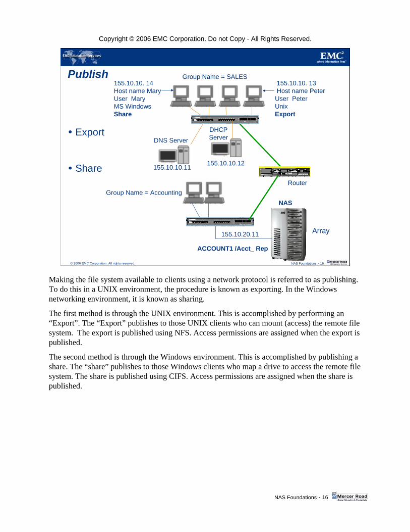
Making the file system available to clients using a network protocol is referred to as publishing. To do this in a UNIX environment, the procedure is known as exporting. In the Windows networking environment, it is known as sharing.
The first method is through the UNIX environment. This is accomplished by performing an “Export”. The “Export” publishes to those UNIX clients who can mount (access) the remote file system. The export is published using NFS. Access permissions are assigned when the export is published.
The second method is through the Windows environment. This is accomplished by publishing a share. The “share” publishes to those Windows clients who map a drive to access the remote file system. The share is published using CIFS. Access permissions are assigned when the share is published.

Copyright © 2006 EMC Corporation. Do not Copy - All Rights Reserved.
NAS Foundations - 17
© 2006 EMC Corporation. All rights reserved. NAS Foundations - 17
Client Access
Mount
MAP
155.10.10. 13Host name Peter User Peter
Unixnfsmount
155.10.10.11
Router
DNS Server
155.10.10. 14 Host name Mary User Mary
MS Windows
MAP
Array
ACCOUNT1 /Acct_ Rep
155.10.20.11
Group Name = SALES
Group Name = AccountingNAS
DHCP Server
155.10.10.12
Once a file system has been published to the network, to gain access, a client will need to mount, or map the remote system to a local access point. In UNIX, this is referred to as the client mount, and in Windows it is referred to as mapping a network drive.
For a client to gain access to a data mount or share, specific user rights and permissions will need to be granted. These are discussed on the following slides.

Copyright © 2006 EMC Corporation. Do not Copy - All Rights Reserved.
NAS Foundations - 18
© 2006 EMC Corporation. All rights reserved. NAS Foundations - 18
File Permissions
Creates File
File Request
155.10.10. 13Host name Peter User Peter
Unix
155.10.10.11
Router
DHCP ServerDNS Server
155.10.10. 14 Host name Mary User Mary
MS Windows
155.10.10.12
Array155.10.20.11
Group Name = SALES
Group Name = Accounting
Account1
/Acct_ Rep
MRPT1 PRPT2Files
NAS
Now that the client has gained access to the shared data, rules of access will need to be adhered to, to prevent uncontrolled data access. In a UNIX environment, one method of achieving this is by using a Network Information Server (NIS) to list and maintain users’ names and permissions. This server will be referenced when a client accesses the data to determine the permissions for access.
In a Windows environment, the Active Directory, Kerberos security, and Domain Controller are responsible for this control and are referenced when a client tries to access network data.

Copyright © 2006 EMC Corporation. Do not Copy - All Rights Reserved.
NAS Foundations - 19
© 2006 EMC Corporation. All rights reserved. NAS Foundations - 19
EMC NAS Platforms
PRODUCTS
We will now take a look at some of the EMC NAS systems available.

Copyright © 2006 EMC Corporation. Do not Copy - All Rights Reserved.
NAS Foundations - 20
© 2006 EMC Corporation. All rights reserved. NAS Foundations - 20
EMC NAS Platforms: Quoted Capacities are Usable
NS350NS500NS700
High availabilityOne or two
Data MoversIntegrated
CLARiiON
DART
NS700: 16 / 32 FC, ATANS500: 8 / 16 FC,16 / 32 FC, ATA
NS350: 4 / 8 FC, 8 FC, ATA
NS704G
Advanced clustering
Four Data Movers
NAS gateway to SAN
CLARiiON, Symmetrix
DART
48 TB FC, ATA
Advanced clustering
Four to eight X-Blades
NAS gateway to SAN
CLARiiON, Symmetrix
DART
112 TB FC, ATA
Celerra NSX
NS500GNS700G
High availabilityOne or two
Data MoversNAS gateway to SAN
CLARiiON, Symmetrix
DART
NS700G: 16 / 32 FC,ATA
NS500G: 8 / 16 FC,16 / 32 FC, ATA
Simple Web-based Management
This slide shows the range of EMC NAS equipment being offered along with some pertinent points of informational reference to each model. Please take a moment to review the slide.
The range of EMC NAS all use the DART (Data Access in Real Time) operating system which is specially developed to provide efficient data transfer between the front end network connections and the backend disk interfaces. There are at presently two configurations available: Gateway and Integrated. The Gateway models provide a NAS interface to SAN/Fabric attached storage arrays, while the Integrated models have their storage arrays contained within the same frame as the NAS heads and Data Movers. However, the storage arrays assigned to the Integrated models are solely dedicated to NAS functionality (no shared host access to disks).

Copyright © 2006 EMC Corporation. Do not Copy - All Rights Reserved.
NAS Foundations - 21
© 2006 EMC Corporation. All rights reserved. NAS Foundations - 21
Celerra NAS - SAN ScalabilityConsolidated storage infrastructure for all applications
NAS front end scales independently of SAN back end
– Connect to multiple Symmetrix, CLARiiON
– Improved utilization
Allocate storage to Celerra and servers as needed
– Easy to move filesystems among Data Movers
– Online filesystem growth
Centralized management for SAN and NAS
iSCSI gateway to SANWindows
UNIX
CLARiiONCX Family
ConnectrixSAN
SymmetrixDMX Family
Celerra NS G Family
Celerra NSX
One of the reasons that EMC NAS scales impressively is due to the gateway architecture that separates the NAS front end (Data Movers) from the SAN back end (Symmetrix or CLARiiON).
This allows the front end and back end to grow independently. Customers can merely add Data Movers to the EMC NAS to scale the front-end performance to handle more clients. As the amount of data increases, you can add more disks, or the EMC NAS can access multiple Symmetrixs’s or CLARiiON’s. This flexibility leads to improved disk utilization.
EMC NAS supports simultaneous SAN and NAS access to the CLARiiON and Symmetrix. and can be added to an existing SAN, with general purpose servers now able to access non-NAS back-end capacity. This extends the improved utilization, centralized management, and Total Cost of Ownership (TCO) benefits of SAN, plus NAS consolidation to EMC NAS, Symmetrix, and CLARiiON.
The configuration can also be reconfigured via software. Since all Data Movers can “see” the entire file space, it is easy to re-assign filesystems to balance the load. In addition, filesystems can be extended on-line as they fill.
Even though the architecture splits the front end among multiple Data Movers and a separate SAN back end, the entire NAS solution can be managed as a single entity.
The Celerra NS Gateway (can be configured with up four Data Movers) and the Celerra NS GS (configured with a single Data Mover) connects to CLARiiON CX arrays and/or Symmetrix DMX arrays through either a fibre channel switch or are directly connected (in the case of CLARiiON).
The NSX gateway model can be configured with between four and eight Data Movers.

Copyright © 2006 EMC Corporation. Do not Copy - All Rights Reserved.
NAS Foundations - 22
© 2006 EMC Corporation. All rights reserved. NAS Foundations - 22
Celerra Family Hardware
NAS FRAME BUILDING BLOCKS
Due to the diversity of the range of EMC NAS systems, we will now briefly review some of the major hardware components to differentiate between the various options available.

Copyright © 2006 EMC Corporation. Do not Copy - All Rights Reserved.
NAS Foundations - 23
© 2006 EMC Corporation. All rights reserved. NAS Foundations - 23
Celerra Family – Control Station Hardware
Disk Array Enclosures
The diagram on this slide illustrates a NS range Control Station ands it‘s default location in the array.

Copyright © 2006 EMC Corporation. Do not Copy - All Rights Reserved.
NAS Foundations - 24
© 2006 EMC Corporation. All rights reserved. NAS Foundations - 24
NSX Control StationThe new high-end EMC NAS device is the NSX, which comes configured standard with two Control Stations
Front ViewNSX Control Station
Rear View
This slide shows the front and back views of the new format Control Stations that are implemented in the NSX range of systems.

Copyright © 2006 EMC Corporation. Do not Copy - All Rights Reserved.
NAS Foundations - 25
© 2006 EMC Corporation. All rights reserved. NAS Foundations - 25
NSX Next Generation Control Station
Celerra NSX – Front view
LEDs and Switches
Power Switch
NMI Switch
Reset Switch ID Switch
Power Boot Sequence LED
Status LED
HDD Act LED
HDD Fault LED Gb # 1 and Gb # 2 LED
USB Connectors 2 and 3
ID LED
Serial Port COM2
This is a close up view of the front of an NSX Control Station showing the control panel and serial connectivity ports.
The Control Station is a dedicated management Intel processor-based computer that monitors and sends commands to the blades. The private network connects the two Control Stations (always shipped on NSX systems) to the blades through the system management switch modules.
Like previous versions, it provides software installation and upgrade services and high-availability features such as fault monitoring, fault recovery, fault reporting (CallHome), and remote diagnosing. Two Control Stations can be connected to a public or private network for remote administration. Each Control Station has a serial port that connects to an external modem so that the Control Station can call home to EMC, or a service provider, if a problem should arise.

Copyright © 2006 EMC Corporation. Do not Copy - All Rights Reserved.
NAS Foundations - 26
© 2006 EMC Corporation. All rights reserved. NAS Foundations - 26
NSX Next Generation Control Station (cont.)
eth3 - Public LAN Port
Celerra NSX – Rear view
COM1 - To serial modem (for Call-Home)
eth0 – Internal Network (To Mgmt. Switch-A in
Enclosure 0)
Video Port
Gb2 – Internal Network(To Mgmt. Switch-B in
Enclosure 0)
Gb1 – IPMI (To eth1 of the other
Control Station)
This slide displays the rear view and connectivity ports of the Next Generation Control Station.

Copyright © 2006 EMC Corporation. Do not Copy - All Rights Reserved.
NAS Foundations - 27
© 2006 EMC Corporation. All rights reserved. NAS Foundations - 27
Celerra Family – Data Mover HardwareSingle or Dual Intel Processors
PCI or PCI-X based
High memory capacity
Multi-port Network cards
Fibre Channel connectivity to storage arrays
No internal storage devices
Redundancy mechanism
NS 700 range and NSX DataMovers have two (2) optical networking ports and six (6) 10/100/100 Ethernet ports for client network connectivity
Fibre I/O module GbE I/O moduleNSX Data Mover
NS 700 Data Mover NS 500 Data Mover
This slide depicts the three forms of Data Movers currently in use on the EMC range of NAS devices.
Each Data Mover is an independent, autonomous file server that transfers requested files to clients and will remain unaffected should a problem arise with another Data Mover. The multiple Data Movers (up to 8 in the NSX and 4 in the NS range) are managed as a single entity. Data Movers are hot pluggable and can be configured with standbys to implement N to 1 availability. A Data Mover (DM) connects to a LAN through FastEthernet and/or Gigabit Ethernet.
The default name for a Data Mover is “server n”, where n was its original slot location in the first NAS frames. This has been perpetuated into the new frames and the naming convention remains “slot” related. For example, in the Golden Eagle/ Eagle frame, a Data Mover can be in slot location 2 through 15 (i.e. server_2 - server_15 in CelerraGolden Eagle/ Eagle frame), therefore the first Data Mover is any frame remains server_2, the second server_3, etc.
There is no remote login capability on the DM, nor do they run any binaries (very secure), and all access to the Data Mover for management and configuration must be performed via the Control Station.
Data Mover redundancy is the mechanism by which the Celerra family reduces the network data outage in the event of a Data Mover failure. The ability to failover the Data Movers is achieved by the creation of a Data Mover configuration database on the Control Station system volumes and is managed via the Control Station. No Data Mover failover will occur if the Control Station is not available for some reason.
Standby Data Mover configuration options:Each standby Data Mover, as a standby for a single primary Data MoverEach standby Data Mover, as a standby for a group of primary Data MoversMultiple standby Data Movers for a primary Data Mover.

Copyright © 2006 EMC Corporation. Do not Copy - All Rights Reserved.
NAS Foundations - 28
© 2006 EMC Corporation. All rights reserved. NAS Foundations - 28
NAS Reference Documentation
NAS Support Matrix– Data Movers– Control Stations– Software supported features
www.emc.com/horizontal/interoperability
When deciding what solution to go with, it is imperative that you make reference to the NAS Support Matrix available at the EMC web site address displayed on the slide.

Copyright © 2006 EMC Corporation. Do not Copy - All Rights Reserved.
NAS Foundations - 29
© 2006 EMC Corporation. All rights reserved. NAS Foundations - 29
Celerra Family Software
SOFTWARE OPERATING SYSTEM
Having briefly reviewed some of the major hardware components, we will now briefly look at the software environment of the high-end EMC NAS offering.
Copyright © 2006 EMC Corporation. Do not Copy - All Rights Reserved.
NAS Foundations - 30
© 2006 EMC Corporation. All rights reserved. NAS Foundations - 30
Celerra Software – Operating SystemsEMC Linux
– This is an industry hardened and EMC modified Operating System loaded on the Control Station to provide
Secure NAS management environmentGrowing in popularity and corporate acceptance
DART – Data Access in Real Time– This is a highly specialized Operating System designed to optimize network traffic
Input/Output throughput and is loaded on the Data Movers– Is multi-threaded to optimize load balancing capabilities of the multi-processor Data
Movers– Advanced volume management - UxFS
Large file size and filesystem supportAbility to extend filesystems onlineMetadata logging for fast recoveryStriped volume support
– Feature rich to support the varied specialized capabilities of the Celerra rangeData Mover FailoverNetworking functionality – Port Aggregation, FailSafe Network device, multi-protocol supportPoint in time Filesystem copiesWindows environmental specialties
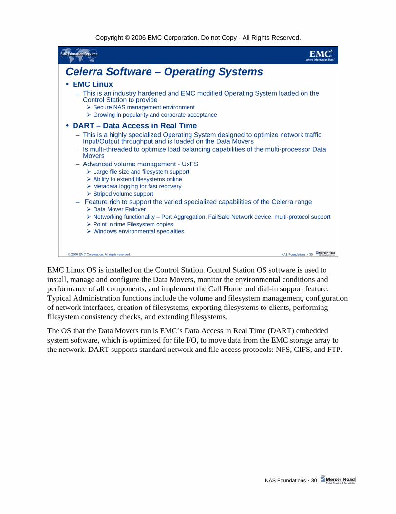
EMC Linux OS is installed on the Control Station. Control Station OS software is used to install, manage and configure the Data Movers, monitor the environmental conditions and performance of all components, and implement the Call Home and dial-in support feature. Typical Administration functions include the volume and filesystem management, configuration of network interfaces, creation of filesystems, exporting filesystems to clients, performing filesystem consistency checks, and extending filesystems.
The OS that the Data Movers run is EMC’s Data Access in Real Time (DART) embedded system software, which is optimized for file I/O, to move data from the EMC storage array to the network. DART supports standard network and file access protocols: NFS, CIFS, and FTP.

Copyright © 2006 EMC Corporation. Do not Copy - All Rights Reserved.
NAS Foundations - 31
© 2006 EMC Corporation. All rights reserved. NAS Foundations - 31
Celerra Family
SOME KEY HIGH AVAILABILITY FEATURES
As we have discussed previously, a key component of a NAS system is high availability and minimal disruption of productivity in the event of failure. We will now briefly review some key, high availability features of the EMC NAS frames.
Copyright © 2006 EMC Corporation. Do not Copy - All Rights Reserved.
NAS Foundations - 32
© 2006 EMC Corporation. All rights reserved. NAS Foundations - 32
Control Station and Data Mover Standby
For hardware high availability the EMC NAS frames implement both Control Station and Data Mover failover capabilities
This means that in the simplest configuration there will be an equivalent system within the frame awaiting a possible failure of the active component, in order to assume the configuration and production role, with minimal outage to the end-users
As the standby system is the equivalent of the production system, there will be no performance or management impact to the environment
To prevent hardware failure impact to the network infrastructure, EMC NAS frames have implemented an N+1 standby capability. This means that both a Data Mover and a Control Station can be protected by an equivalent standby component that will assume production in the unlikely event of a primary component failure. A system can also be configured for a many primary to one standby, in the case of the Data Movers. Multiple primary Data Movers can be protected by a single standby Data Mover and this configuration could be implemented if the data behind the primary Data Movers does not warrant a one to one data protection configuration.
Copyright © 2006 EMC Corporation. Do not Copy - All Rights Reserved.
NAS Foundations - 33
© 2006 EMC Corporation. All rights reserved. NAS Foundations - 33
Data Mover StandbyData Mover failover is a policy driven mechanism controlled by the Control Station
The policy is as follows– Automatic
When configured like this, the Control Station will detect a Data Mover failure, power down the failed Data Mover and bring the designated standby Data Mover on line with the failed DM personality
– RetryWith this configuration, the Control Station will detect a Data Mover failure, try and reboot the failed Data Mover, if the reboot does not clear the error, power down the failed Data Mover and bring the designated standby Data Mover on line with the failed DM personality
– ManualWhen configured like this no action is taken and administrator intervention is required for failover
In all cases failback is a manual process
Data Mover stand-by is policy controlled. The three options of the policy are Automatic, Retry, and Manual. In all cases, failback is a manual process. Please take a moment to review the policies described on the slide.These Standby Data Movers are powered and ready to assume the personality of their associated Primary Data Movers, in the event of a failure. If a Primary Data Mover fails, the Control Station will detect the failure and initiate the failover process. The failover procedure, in an Automatic configuration, is as follows.
The Control Station will: 1. Remove power from the failed Data Mover. 2. Set the location for the Standby Data Mover to assume its “new” personality in the configuration
database.3. Control the personality take over and allow the Standby Data Mover to assume the primary role,
thereby enabling clients to re-access their data transparently via the standby.
Once the failed Data Mover is repaired, the failback mechanism is always manually administrator initiated. This process is the reverse of the failover process and restores the primary functionality to the repaired Primary Data Mover and returns the Standby Data Mover into its standby state in preparation for any future outage.
There are three operational modes of operation for Failover: Automatic, Retry, and Manual. 1. Automatic Mode: the Control Station detects the failure of a Data Mover. The failover process
occurs without trying any recovery process first.2. Retry Mode: the Control Station detects the failure, an attempt to reboot the failed Data Mover is
tried first before the failover procedure is initiated.3. Manual Mode: the Control Station will detect the failure and remove power from the failed Data
Mover. However, no further Data Mover recovery action will be taken until administrative intervention.
Recovery after a Data Mover failover is always a manual process.
Copyright © 2006 EMC Corporation. Do not Copy - All Rights Reserved.
NAS Foundations - 34
© 2006 EMC Corporation. All rights reserved. NAS Foundations - 34
NS Series NetworkingNetwork interfaces– Ethernet– Gigabit Ethernet
Network protocols– TCP/IP, UDP/IP – CIFS, NFS V2, V3 and V4– FTP, TFTP, and SNMP– NDMP V2, V3, and V4 – NTP, SNTP– iSCSI target
Feature support– Link aggregation– FailSafe Networking– Ethernet Trunking– Virtual LAN
Trunking
SNMP
TCP
NDMP
CIFSFTP
iSCSI
NFS
VLAN
Gigabit Ethernet
FSN Ethernet
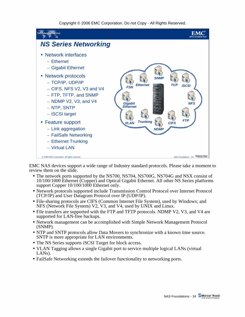
EMC NAS devices support a wide range of Industry standard protocols. Please take a moment to review them on the slide.
The network ports supported by the NS700, NS704, NS700G, NS704G and NSX consist of 10/100/1000 Ethernet (Copper) and Optical Gigabit Ethernet. All other NS Series platforms support Copper 10/100/1000 Ethernet only.Network protocols supported include Transmission Control Protocol over Internet Protocol (TCP/IP) and User Datagram Protocol over IP (UDP/IP).File-sharing protocols are CIFS (Common Internet File System), used by Windows; and NFS (Network File System) V2, V3, and V4, used by UNIX and Linux.File transfers are supported with the FTP and TFTP protocols. NDMP V2, V3, and V4 are supported for LAN-free backups.Network management can be accomplished with Simple Network Management Protocol (SNMP).NTP and SNTP protocols allow Data Movers to synchronize with a known time source. SNTP is more appropriate for LAN environments.The NS Series supports iSCSI Target for block access.VLAN Tagging allows a single Gigabit port to service multiple logical LANs (virtual LANs).FailSafe Networking extends the failover functionality to networking ports.

Copyright © 2006 EMC Corporation. Do not Copy - All Rights Reserved.
NAS Foundations - 35
© 2006 EMC Corporation. All rights reserved. NAS Foundations - 35
Network FailSafe Device
Network outages, due to environmental failure, are more common than Data Mover failures
Network FailSafe Device – DART OS mechanism to minimize data access disruption due to
these failures – Logical device is created using either physical ports or other logical
ports combined together to create redundant groups of ports– Logically grouped Data Mover network ports monitor network traffic
on the ports– Active FailSafe Device port senses traffic disruption– Standby (non-active) port assumes the IP Address and Media
Access Control address in a very short space of time, thus reducing data access disruption
Having discussed the maintenance of data access via redundant Data Movers, we will now discuss the same concept utilizing network port mechanisms. First, let’s look at the Network Failsafe device. Network outages due to environmental failures are more common than Data Mover failures. To minimize data access disruption due to these failures, the DART OS has a mechanism that is environment agnostic, the Network FailSafe Device.
This is a mechanism by which the Network ports of a Data Mover may be logically grouped together into a partnership that will monitor network traffic on the ports. If the currently active port senses a disruption of traffic, the standby (non-active) port will assume the active role in a very short space of time, thus reducing data access disruption.
The way this works is a logical device is created, using either physical ports or other logical ports, combined together to create redundant groups of ports.
In normal operation, the active port will carry all network traffic. The standby (non-active port) will remain passive until a failure is detected. Once a failure has been detected by the FailSafe Device, this port will assume the network identity of the active port, including IP Address and Media Access Control Address.
Having assumed the failed port identity, the standby port will now continue the network traffic. Network disruption due to this change over is minimal, and may only be noticed in a high transaction oriented NAS implementation, or in CIFS environments, due to the connection-oriented nature of the protocol.
There are several benefits achieved by configuring the network FailSafe device: 1. Configuration is handled transparently to client access2. The ports that make up the FailSafe device need not be of the same type3. Rapid recovery from a detected failure4. Can be combined with logical Aggregated Port devices to provide even higher levels of redundancy.
Although the ports that make up the FailSafe device need not be of the same type, care must be taken to ensure that once failover has occurred, that client expected response times remain relatively the same and data access paths are maintained.

Copyright © 2006 EMC Corporation. Do not Copy - All Rights Reserved.
NAS Foundations - 36
© 2006 EMC Corporation. All rights reserved. NAS Foundations - 36
Link Aggregation - High Availability Link aggregation is the combining of two or more data channels into a single data channel for high availability– Two Methods: IEEE 802.3ad LACP & CISCO FastEtherChannel
IEEE 802.3ad LACP – Combining links for improved
availability
– If one port fails, other ports take over
– Industry standard IEEE 802.3ad
– Combines 2–12 Ethernet ports into a single virtual link
– Deterministic behavior
– Does not increase single client throughput
LINK
Industry Standard SwitchCelerra
The Celerra also supports two forms of link aggregation. The first form is the IEEE 802.3ad link aggregation control protocol. This is an industry standard methodology of aggregating network ports to provide path redundancy.
The purpose for combining data channels in the EMC implementation is to achieve redundancy and fault tolerance of network connectivity. It is commonly assumed that link aggregation will provide a single client with a data channel bandwidth equal to the sum of the bandwidths of individual member channels. This is not, in fact, the case due to the methodology of channel utilization, and it may only be achieved with very special considerations to the client environment. The overall channel bandwidth is increased, but the client will only receive, under normal working conditions, the bandwidth equal to one of the component channels.

Copyright © 2006 EMC Corporation. Do not Copy - All Rights Reserved.
NAS Foundations - 37
© 2006 EMC Corporation. All rights reserved. NAS Foundations - 37
Channel
CISCO Switch
Celerra
Link Aggregation - High Availability (cont.)
CISCO FastEtherChannel– Port grouping for improved
availability – Combines 2, 4, or 8 Ethernet
ports into a single virtual device– Inter-operates with trunking-
capable switches – High availability—if one port fails,
other ports take over– Does not increase single client
throughput
The second form of link aggregation is the Cisco proprietary FastEtherChannel. This methodology is mainly supported with Cisco networking and provides fundamentally the same characteristics as the IEEE 802.3ad link aggregation control protocol mechanism.
A comparison table is included here defining the differences between the two methodologies.

Copyright © 2006 EMC Corporation. Do not Copy - All Rights Reserved.
NAS Foundations - 38
© 2006 EMC Corporation. All rights reserved. NAS Foundations - 38
Network Redundancy - High Availability
An example of FSN and Port aggregation co-operation
These network redundancy mechanisms can be combined to provide a highly available network environment as is illustrated on the slide. In both cases of link aggregation, individual client bandwidth is not increased. Therefore, they are primarily used for redundancy.

Copyright © 2006 EMC Corporation. Do not Copy - All Rights Reserved.
NAS Foundations - 39
© 2006 EMC Corporation. All rights reserved. NAS Foundations - 39
Celerra Family Environment Management Integration
VIRTUAL LOCAL AREA NETWORKS
Let’s now look at a networking management tool, Virtual Local Area Networks, or VLANs.
Copyright © 2006 EMC Corporation. Do not Copy - All Rights Reserved.
NAS Foundations - 40
© 2006 EMC Corporation. All rights reserved. NAS Foundations - 40
VLAN Support
Create logical LAN segment
– Divide a single LAN into logical segments
– Join multiple separate segments into one logical LAN
VLAN Tagging– 802.1q
Simplified Management– No network
reconfiguration required for member relocation
Hub Hub
Hub Hub
Bridge
or
Switch
Bridge
or
Switch
Hub Hub
Router
Workstation VLAN B
VLAN B
VLAN A
VLAN A
Collision DomainLAN Segment
Collision DomainLAN Segment
Collision Domain
LAN Segment
Broadcast Domain
LAN
Broadcast Domain LAN
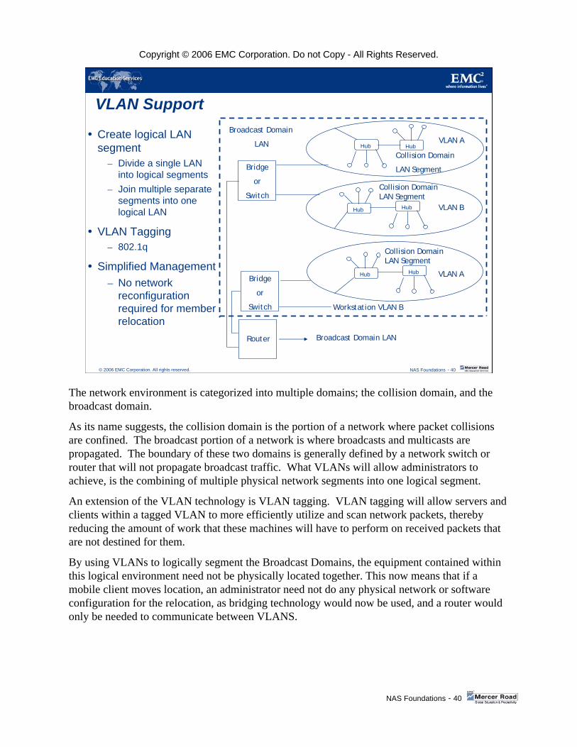
The network environment is categorized into multiple domains; the collision domain, and the broadcast domain.
As its name suggests, the collision domain is the portion of a network where packet collisions are confined. The broadcast portion of a network is where broadcasts and multicasts are propagated. The boundary of these two domains is generally defined by a network switch or router that will not propagate broadcast traffic. What VLANs will allow administrators to achieve, is the combining of multiple physical network segments into one logical segment.
An extension of the VLAN technology is VLAN tagging. VLAN tagging will allow servers and clients within a tagged VLAN to more efficiently utilize and scan network packets, thereby reducing the amount of work that these machines will have to perform on received packets that are not destined for them.
By using VLANs to logically segment the Broadcast Domains, the equipment contained within this logical environment need not be physically located together. This now means that if a mobile client moves location, an administrator need not do any physical network or software configuration for the relocation, as bridging technology would now be used, and a router would only be needed to communicate between VLANS.

Copyright © 2006 EMC Corporation. Do not Copy - All Rights Reserved.
NAS Foundations - 41
© 2006 EMC Corporation. All rights reserved. NAS Foundations - 41
VLAN – Implementation Methodologies
There are two primary methodologies of implementing VLANS– By IP address subnetting
Using this methodology an administrator will configure the broadcast domains to encompass the whole network area for specific groups of computers, by using BridgeRouter technology
– By VLAN TaggingUsing this methodology an administrator will configure groups of user computers to embed an identification tag embedded into all of their Ethernet packet traffic
Two common forms of VLAN implementation are IP address subnetting, and VLAN tagging. The former entails an Administrator configuring broadcast domains to encompass the whole network for specific groups of computers. This is achieved by using specialized networking hardware (BridgeRouters). The second methodology uses the embedding of a specific tag within the Ethernet packets for specific groups of computers.
VLAN Tagging, (802.1q.), allows a single Gigabit Data Mover port to service multiple logical LANs (Virtual LANs). This allows data network nodes to be configured (added and moved as well as other changes) quickly and conveniently from the management console, rather than in the wiring closet. VLAN also allows a customer to limit traffic to specific elements of a corporate network, and protect against broadcasts (such as denial of service) affecting whole networks. Standard router based security mechanisms can be used with VLANs to restrict access and improve security.
Copyright © 2006 EMC Corporation. Do not Copy - All Rights Reserved.
NAS Foundations - 42
© 2006 EMC Corporation. All rights reserved. NAS Foundations - 42
VLAN - BenefitsPerformance
– This is client related as packets not destined for a machine in a particular VLAN will not be processed by the client
Reduced Router OverheadReduced Costs
– expensive routers and billable traffic routing costs can be reduced
Security– placing users into a tagged
VLAN environment will prevent unauthorized access to network packets
VLAN-A VLAN S VLAN E
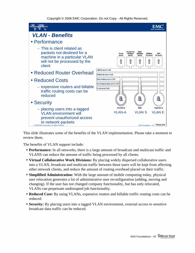
This slide illustrates some of the benefits of the VLAN implementation. Please take a moment to review them.
The benefits of VLAN support include:Performance: In all networks, there is a large amount of broadcast and multicast traffic and VLANS can reduce the amount of traffic being processed by all clients.Virtual Collaborative Work Divisions: By placing widely dispersed collaborative users into a VLAN, broadcast and multicast traffic between these users will be kept from affecting other network clients, and reduce the amount of routing overhead placed on their traffic.Simplified Administration: With the large amount of mobile computing today, physical user relocation generates a lot of administrative user reconfiguration (adding, moving and changing). If the user has not changed company functionality, but has only relocated, VLANs can perpetuate undisrupted job functionality. Reduced Cost: By using VLANs, expensive routers and billable traffic routing costs can be reduced.Security: By placing users into a tagged VLAN environment, external access to sensitive broadcast data traffic can be reduced.

Copyright © 2006 EMC Corporation. Do not Copy - All Rights Reserved.
NAS Foundations - 43
© 2006 EMC Corporation. All rights reserved. NAS Foundations - 43
Celerra Family Software Management
USER INTERFACES
The previous slides dealt with environmental management. We're now going to examine the different user interfaces for Celerra management.

Copyright © 2006 EMC Corporation. Do not Copy - All Rights Reserved.
NAS Foundations - 44
© 2006 EMC Corporation. All rights reserved. NAS Foundations - 44
Celerra Management – Command LineThe command line can be accessed on the Control Station via– An ssh interface tool, e.g. PuTTy– Telnet
Its primary function is for the scripting of common repetitive tasks that may run on a predetermined schedule to ease administrative burden
It has approximately 80 UNIX command-like commands– nas_ - These commands are generally for the configuration and
management of global resources– server_ - These commands are generally for the configuration and
management of Data Mover specific resources– fs_ - These commands are generally for special file system
operations
The first interface we will discuss, and the most powerful, is the Command Line Interface.
The primary function of this interface is to perform one-off tasks, or to create scripts to perform multiple repetitive tasks in one operation. These command structures are similar to UNIX command structures.

Copyright © 2006 EMC Corporation. Do not Copy - All Rights Reserved.
NAS Foundations - 45
© 2006 EMC Corporation. All rights reserved. NAS Foundations - 45
Celerra Manager – GUI Management
The other Celerra specific interface is the GUI access methodology of the Celerra Manager. This is built into the Linux operating system that runs on the Control Station and is launched through a web browser session.
There are two version of this interface, Basic and Advanced, that are installed along with the EMC Linux on to the Control Station. The options are enabled with the purchase of additional licenses to access differing levels of feature support.

Copyright © 2006 EMC Corporation. Do not Copy - All Rights Reserved.
NAS Foundations - 46
© 2006 EMC Corporation. All rights reserved. NAS Foundations - 46
Celerra Manager – GUI Wizards
In line with most graphical interfaces available today, there are several wizards that will assist administrators to perform some fundamental management and configuration tasks.

Copyright © 2006 EMC Corporation. Do not Copy - All Rights Reserved.
NAS Foundations - 47
© 2006 EMC Corporation. All rights reserved. NAS Foundations - 47
Celerra Manager – GUI Tools
Along with wizards, there are several additional GUI tools, such as a SSH shell interface and Celerra Monitor, to assist with administration and configuration. Once again, these are dependant upon the licensing options purchased.

Copyright © 2006 EMC Corporation. Do not Copy - All Rights Reserved.
NAS Foundations - 48
© 2006 EMC Corporation. All rights reserved. NAS Foundations - 48
EMC ControlCenter V5.x.x NAS SupportDiscovery and monitoring – Data Movers– Devices and volumes– Network adapters and IP
interfaces– Mount points– Exports– Filesystems (including snapshots
and checkpoints)
The last management interface is that of the EMC management flagship, EMC Control Center. The management integration is not as advanced as the Celerra Manager, but will become enhanced with further releases of EMC Control Center.

Copyright © 2006 EMC Corporation. Do not Copy - All Rights Reserved.
NAS Foundations - 49
© 2006 EMC Corporation. All rights reserved. NAS Foundations - 49
Celerra Family File System Management
AUTOMATIC VOLUME MANAGEMENT
To assist with ease of management and file system creation, the Celerra uses a built in volume manager to provide known, predictable performance and management parameters.
Copyright © 2006 EMC Corporation. Do not Copy - All Rights Reserved.
NAS Foundations - 50
© 2006 EMC Corporation. All rights reserved. NAS Foundations - 50
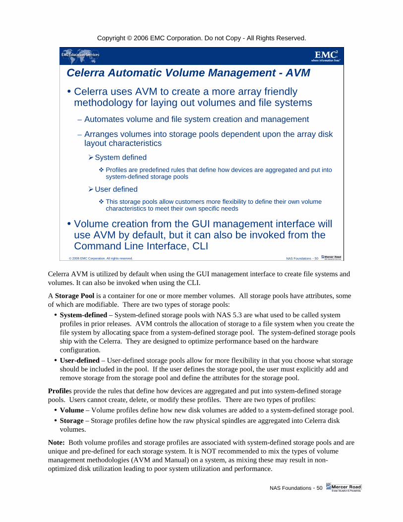
Celerra Automatic Volume Management - AVMCelerra uses AVM to create a more array friendly methodology for laying out volumes and file systems– Automates volume and file system creation and management
– Arranges volumes into storage pools dependent upon the array disk layout characteristics
System definedProfiles are predefined rules that define how devices are aggregated and put into system-defined storage pools
User definedThis storage pools allow customers more flexibility to define their own volume characteristics to meet their own specific needs
Volume creation from the GUI management interface will use AVM by default, but it can also be invoked from the Command Line Interface, CLI
Celerra AVM is utilized by default when using the GUI management interface to create file systems and volumes. It can also be invoked when using the CLI.
A Storage Pool is a container for one or more member volumes. All storage pools have attributes, some of which are modifiable. There are two types of storage pools:
System-defined – System-defined storage pools with NAS 5.3 are what used to be called system profiles in prior releases. AVM controls the allocation of storage to a file system when you create the file system by allocating space from a system-defined storage pool. The system-defined storage pools ship with the Celerra. They are designed to optimize performance based on the hardware configuration. User-defined – User-defined storage pools allow for more flexibility in that you choose what storage should be included in the pool. If the user defines the storage pool, the user must explicitly add and remove storage from the storage pool and define the attributes for the storage pool.
Profiles provide the rules that define how devices are aggregated and put into system-defined storage pools. Users cannot create, delete, or modify these profiles. There are two types of profiles:
Volume – Volume profiles define how new disk volumes are added to a system-defined storage pool.Storage – Storage profiles define how the raw physical spindles are aggregated into Celerra disk volumes.
Note: Both volume profiles and storage profiles are associated with system-defined storage pools and are unique and pre-defined for each storage system. It is NOT recommended to mix the types of volume management methodologies (AVM and Manual) on a system, as mixing these may result in non-optimized disk utilization leading to poor system utilization and performance.

Copyright © 2006 EMC Corporation. Do not Copy - All Rights Reserved.
NAS Foundations - 51
© 2006 EMC Corporation. All rights reserved. NAS Foundations - 51
AVM – System Defined Storage Poolssymm_std
– Highest performance, medium cost, using Symmetrix STD disk volumes
symm_std_rdf_src– Highest performance, medium cost, using SRDF
clar_r1– High performance, low cost, using CLARiiON CLSTD disk volumes in RAID 1
clar_r5_performance– Medium performance, low cost, using CLARiiON CLSTD disk volumes in 4+1 RAID 5
clar_r5_economy– Medium performance, lowest cost, using CLARiiON CLSTD disk volumes in 8+1 RAID 5
clarata_archive– 6+1, low performance, high capacity, using CLARiiON Serial ATA disk volumes RAID 5
clarata_r3– 4+1 or 8+1, RAID 3, archival performance using CLARiiON Serial ATA disk volumes and
NDMP2D feature
This slide provides a list of the currently defined storage pools supported on the Celerra. Please take a moment to review them.
The clarata_r3 storage pool is specifically used by the NDMP2D feature which is discussed later in the course.
The Data Management Protocol to Disk (NDMP2D) feature is the creation of a software Virtual Tape Library emulation on ATA disks for Celerra backup purposes. This will be discussed in later slides.
symm = Symmetrix
clar = CLARiiON
STD = Standard
CLSTD = CLARiiON Standard
clarata = CLARiiON ATA drives

Copyright © 2006 EMC Corporation. Do not Copy - All Rights Reserved.
NAS Foundations - 52
© 2006 EMC Corporation. All rights reserved. NAS Foundations - 52
Celerra Family Management Software
WINDOWS SPECIFIC INTEGRATION OPTIONS
Celerra started its life as a purely NFS and UNIX environment NAS frame. However, with the addition of the CIFS protocol support, the Microsoft Windows environment has begun to play a large role in the implementation of this frame.
As such, the way to provide integration into the environment has been modified dramatically. In the next few slides we will take a brief look at some of the tools implemented to ease this integration.

Copyright © 2006 EMC Corporation. Do not Copy - All Rights Reserved.
NAS Foundations - 53
© 2006 EMC Corporation. All rights reserved. NAS Foundations - 53
Windows Environment IntegrationTo achieve a tightly integrated Windows active directory environment, EMC NAS uses several software features– usermapper
This is a feature that will help the Celerra automatically assign UNIX user and group identifiers, UIDs and GIDs, to Windows users and groups. This assists Windows administrators with the integration of these specialized NAS frames, as there is minimal or no user environment modification
– UNIX User ManagementActive Directory migration tool
MMC plug-in extension for Active
Directory uses and computers
Celerra Management tool snap-in
(MMC Console)
Several software tools are listed on the slide. Please take a moment to review them.
The tools include:The Active Directory (AD) Migration tool — Migrates the Windows/UNIX user and group mappings to Active Directory. The matching users/groups are displayed in a property page with a separate sheet for users and groups. The Administrator selects the users/groups that should be migrated and de-selects those that should not be migrated, or should be removed from Active Directory.The Microsoft Management Console (MMC) — Snap-in extension for AD users and computers. This adds a property page to the user’s property sheet to specify UID (User ID), GID (Group ID), and Comment, and adds a property page to the group property sheet to specify GID/Comment. You can only manage users and groups of the local tree.The Celerra Management Tool (MMC Console) — Snap-in extension for Dart UNIX User Management displays Windows users/groups which are mapped to UNIX attributes. It also displays all domains that are known to the local domain (Local Tree, Trusted domains).

Copyright © 2006 EMC Corporation. Do not Copy - All Rights Reserved.
NAS Foundations - 54
© 2006 EMC Corporation. All rights reserved. NAS Foundations - 54
Windows Environment Integration (cont.)– Virus Checker Management
Celerra Management toolMMC Console
– Home Directory snap-inAllows multiple points of entry to a single share
– Data Mover security snap-inManage user rights and auditing
Additional tools are listed here. Please take a moment to review them.The Celerra Management Tool (MMC Console)—Snap-in extension for Dart Virus Checker Management which manages parameters for the DART Virus Checker.The Home Directories capability in the Celerra allows a customer to set up multiple points of entry to a single Share/Export. This avoids sharing out many hundreds of points of entry to a filesystem for each individual user, for storing their Home Directories. The MMC Snap-in provides a simple and familiar management interface for Windows administrators for this capability.The Data Mover Security Settings Snap-in provides a standard Windows interface for managing user rights assignments, as well as the settings for which statistics Celerra should audit, based on the NT V4 style auditing policies.

Copyright © 2006 EMC Corporation. Do not Copy - All Rights Reserved.
NAS Foundations - 55
© 2006 EMC Corporation. All rights reserved. NAS Foundations - 55
Virtual Data Movers
Virtual Data Movers on Single Physical Data Movers– Another improvement to the Windows integration is the ability to
create multiple virtual CIFS servers on each logical Data Mover– This is achieved by creating Virtual Data Mover environments– This is a huge benefit to the consolidation of multiple server file
serving functionality onto single Data Movers as each virtual Data Mover can maintain isolated CIFS servers with their own root filesystem environment
– This will allow whole Virtual Data Mover environments to be loaded, unloaded, or even replicated between physical Data Movers for ease in Windows environmental management
In pre DART v5.2, a Data Mover supported one NFS server and multiple CIFS servers, where each server has the same view of all the resources. The CIFS servers are not logically isolated and although they are very useful in consolidating multiple servers into one Data Mover, they do not provide the isolation between servers as needed in some environments, such as data from disjointed departments hosted on the same Data Mover.
Now, VDMs support separate isolated CIFS servers, allowing you to place one or multiple CIFS servers into a VDM, along with their file systems. The servers residing in a VDM store their dynamic configuration information (such as local groups, shares, security credentials, and audit logs, etc.) in a configuration file system. A VDM can then be loaded and unloaded, moved from Data Mover to Data Mover, or even replicated to a remote Data Mover as an autonomous unit. The servers, their file systems, and all of the configuration data that allows clients to access the file systems are available in one virtual container.
VDMs provide virtual partitioning of the physical resources and independently contain all the information necessary to support the contained CIFS servers. Having the file systems and the configuration information contained in a VDM does the following:• Enables administrators to separate CIFS servers and give them access to specified shares;• Allows replication of the CIFS environment from primary to secondary without impacting server access;• Enables administrators to easily move CIFS servers from one physical Data Mover to another.
A VDM can contain one or more CIFS servers. The only requirement is that you have at least one interface available for each CIFS server you create. The CIFS servers in each VDM have access only to the file systems mounted to that VDM, and therefore can only create shares on those file systems mounted to the VDM. This allows a user to administratively partition or group their file systems and CIFS servers.

Copyright © 2006 EMC Corporation. Do not Copy - All Rights Reserved.
NAS Foundations - 56
© 2006 EMC Corporation. All rights reserved. NAS Foundations - 56
Celerra Family Business Continuity
DISK BASED REPLICATION AND RECOVERY SOLUTIONS
Having integrated the Celerra into the environment, we will now briefly review some data replication and recovery solutions that augment the environment.

Copyright © 2006 EMC Corporation. Do not Copy - All Rights Reserved.
NAS Foundations - 57
© 2006 EMC Corporation. All rights reserved. NAS Foundations - 57
Disk-Based Replication and Recovery Solutions
NS & NSX / Symmetrix
Celerra / FC4700
SynchronousSynchronousDisasterDisasterRecoveryRecovery
SRDFSRDF
Seconds
FileFileRestorationRestoration
Celerra SnapSure Celerra SnapSure
Hours
FileFile--basedbasedReplicationReplicationTimeFinder/FSTimeFinder/FS
Celerra ReplicatorCelerra ReplicatorEMC OnCourseEMC OnCourse
Minutes
NS / CLARiiON
CelerraNS
FUN
CTI
ON
ALIT
Y
RECOVERY TIME
High-end environments require non-stop access to the information pool. From a practical perspective, not all data carries the same value. The slide illustrates that EMC Celerra provides a range of disk-based replication tools for each recovery time requirement. Please take a moment to review the slide.
File restoration: This is the information archived to disk and typically saved to tape. Here we measure recovery in hours. Celerra SnapSure enables local point-in-time replication for file un-deletes and backups.
File-based replication: This information is recoverable in time frames measured in minutes. Information is mirrored to disk by TimeFinder, and the copy is made accessible with TimeFinder/FS. The CelerraReplicator creates replicas of production filesystems either locally or at a remote site. Recovery time from the secondary site depends on the bandwidth of the IP connection between the two sites. EMC OnCourseprovides secure, policy-based file transfers.
The Replicator feature supports “data recovery” for both CIFS and NFS by allowing the secondary filesystem (SFS) to be manually switched to read/write mode after the Replicator session has been stopped, either manually or due to a destructive event. (Note: There is no re-synch or “failback”capability).
Synchronous disaster recovery: This is the information requiring disaster recovery with no loss of transactions. This strategy allows customers to have data recovery in seconds. SRDF, in synchronous mode, facilitates real-time remote mirroring in campus environments (up to 60 km).
File restoration and file-based replication (Celerra Replicator, EMC OnCourse) are available with Celerra/CLARiiON. The entire suite of file restoration, file-based replication, and synchronous disaster recovery are available with Celerra /Symmetrix.

Copyright © 2006 EMC Corporation. Do not Copy - All Rights Reserved.
NAS Foundations - 58
© 2006 EMC Corporation. All rights reserved. NAS Foundations - 58
Disaster Recovery
CELERRA SYMMETRIX REMOTE DATA FACILITY
Celerra disaster recovery, when integrated with the Symmetrix, utilizes a very synergistic combination of both the Celerra and the Symmetrix functionality.

Copyright © 2006 EMC Corporation. Do not Copy - All Rights Reserved.
NAS Foundations - 59
© 2006 EMC Corporation. All rights reserved.
Celerra SRDF – Disaster Recovery
Celerra synchronous disaster recovery solution– Allows an administrator to configure remote standby Data Movers waiting to assume primary
roles in the event of a disaster occurring at the primary data site– SRDF allows administrator to achieve a remote synchronous copy of production filesystems at a
remote location– Real-time, logically synchronized and consistent copies of selected volumes– Uni-directional and bi-directional support– Resilient against drive, link, and server failures– No lost I/Os in the event of a disaster– Independent of CPU, operating system, application, or database– Simplifies disaster recovery switchover and back
CelerraCelerraUni or bi-directional
Campus (60 km) distance
Network
Increases data availability by combining the high availability of the Celerra family with the Symmetrix Remote Data Facility
In the NAS environment, data availability is one of the key aspects for implementation determination. By combining the high availability of the Celerra family with the SymmetrixRemote Data Facility, the data available increases exponentially. What the SRDF feature allows an administrator to achieve is a remote synchronous copy of production filesystems at a remote location. However, as this entails the creation of Symmetrix specific R1 and R2 data volumes, this functionality is currently restricted to Celerra / Symmetrix implementations only.
This feature allows an administrator to configure remote standby Data Movers waiting to assume primary roles in the event of a disaster occurring at the primary data site. Due to data latency issues, this solution is restricted to a campus distance of separation between the two data sites (60 network km).
The SRDF solution for Celerra can leverage an existing SRDF transport infrastructure to support the full range of supported SAN (Storage Area Network) and DAS (Direct-attached Storage) connected general purpose server platforms.
The Celerra disaster recovery solution maintains continuously available filesystems, even with an unavailable or non-functioning Celerra. Symmetrix technology connects a local and remote Celerra over a distance of up to 40 miles (66 km) via an ESCON or Fiber Channel SRDF connection. After establishing the connection and properly configuring the Celerra, users gain continued access to filesystems in the event that the local Celerra and/or the Symmetrixbecomes unavailable.
(Continued)

Copyright © 2006 EMC Corporation. Do not Copy - All Rights Reserved.
NAS Foundations - 60
© 2006 EMC Corporation. All rights reserved.
Celerra SRDF – Disaster Recovery (cont.)
Celerra synchronous disaster recovery solution– Allows an administrator to configure remote standby Data Movers waiting to assume primary
roles in the event of a disaster occurring at the primary data site– SRDF allows administrator to achieve a remote synchronous copy of production filesystems at a
remote location– Real-time, logically synchronized and consistent copies of selected volumes– Uni-directional and bi-directional support– Resilient against drive, link, and server failures– No lost I/Os in the event of a disaster– Independent of CPU, operating system, application, or database– Simplifies disaster recovery switchover and back
CelerraCelerraUni or bi-directional
Campus (60 km) distance
Network
Increases data availability by combining the high availability of the Celerra family with the Symmetrix Remote Data Facility
The Celerra systems communicate over the network to ensure the primary and secondary Data Movers are synchronized with respect to meta data, while the physical data is transported over the SRDF link. In order to ensure an up to date and consistent copy of the filesystems on the remote Celerra, the synchronous mode of SRDF operation is currently the only supported SRDF operational mode. Implementation of Celerra disaster recovery software requires modification of the standard Celerra configuration.
SRDF has two modes of operation: active-passive and active-active. Active-passive (Uni-directional) SRDF support means that one Celerra provides active Data Mover access while a second (remote) Celerra provides all Data Movers as failover. Active-active (Bi-directional) SRDF support means that one Celerra can serve local needs while reserving some of its Data Movers for recovery of a remote Celerra, which will reserve some of its Data Movers for recovery of the first Celerra . In addition, local failover Data Movers can be associated with Data Movers in the primary Symmetrix to ensure that local failover capability is initiated in the unlikely event there is a hardware related issue with a specific Data Mover.
The mode of operation with SRDF/S is active-cctive. With active-active (SRDF/S only) support, one NS Series/NSX Gateway can serve local needs while reserving some of its Data Movers for recovery of a remote NS Series/NSX Gateway, which will reserve some of its Data Movers for recovery of the first NS Series/Gateway.
Copyright © 2006 EMC Corporation. Do not Copy - All Rights Reserved.
NAS Foundations - 61
© 2006 EMC Corporation. All rights reserved. NAS Foundations - 61
Data Replication
SNAPSURE, TIMEFINDER/FS, Celerra SRDF/A,CELERRA REPLICATOR, FileMover &
DiskXtender
Besides SRDF, Celerra has several other mechanisms for data replication and recovery. We will briefly review these in the next few slides.

Copyright © 2006 EMC Corporation. Do not Copy - All Rights Reserved.
NAS Foundations - 62
© 2006 EMC Corporation. All rights reserved. NAS Foundations - 62
Celerra SnapSure - Data Replication
Enables speedy recovery– Low volume activity, read-only
applications– Simple file undelete– Incremental backup
Logical point-in-time view of Celerra data– Works for all Celerra
Implementations– Saves disk space– Maintains pointers to track changes
to the primary filesystem – Not a mirror; creation of specialized
volumes (R1/R2, BCVs) not required
Productionfilesystem
Checkpoint
Celerra CLARiiON orSymmetrix
The first methodology we will review is the storage array agnostic solution. This is the CelerraSnapSure feature. This solution allows point in time views of a production file system, without overly impacting production I/O. It achieves this by moving data to a separate, dedicated storage area, SavVol, before data modification is allowed on the production file system. Any application that requires a view of the point in time image of the file system will be directed to the data in the SavVol, in the case of Production File System, (PFS), modified data, and to the production file system, in the case of non-modified data.
One of the obvious benefits of this solution is that it is storage array agnostic (e.g. works for all NAS DART implementations). This also means that there are no specialized volumes that need to be configured for this feature to function. Some other replication methodologies, such as SRDF and TimeFinder/FS, are dependent on the creation of Symmetrix Remote Data Facility and Business Continuity Volumes in the Symmetrix. SnapSure does not require any specialized volume creation and will therefore work with any back-end storage array (CLARiiON or Symmetrix).
Multiple checkpoints can be done on the Production Filesystem thereby facilitating the ability to recover different point-in-time images of files or file systems.

Copyright © 2006 EMC Corporation. Do not Copy - All Rights Reserved.
NAS Foundations - 63
© 2006 EMC Corporation. All rights reserved. NAS Foundations - 63
Celerra SnapSure - Management
Multiple Checkpoints for recovery of different point-in-time images– GUI Checkpoint schedule manipulation– Checkpoint out of order delete – Automatic mounting upon creation
The slide identifies several SnapSure management options. Please take a moment to review them.
While checkpoint technology is dependant on chronological linking for maintaining SnapSuredata integrity, the DART 5.2 software will support out of order deletion of checkpoints. This feature allows customers to delete any checkpoint and not affect the point-in-time view of any other checkpoint. A customer may also delete a single scheduled checkpoint instead of the entire schedule, and refresh any individual checkpoint, instead of only the oldest.
Checkpoints are automatically mounted on creation, and maintained on a hidden checkpoint directory . This new hidden directory will allow changing the default name (yyy_dd_hh_mm_ss_GMT) into something more administratively friendly.

Copyright © 2006 EMC Corporation. Do not Copy - All Rights Reserved.
NAS Foundations - 64
© 2006 EMC Corporation. All rights reserved. NAS Foundations - 64
Celerra TimeFinder/FS - Data ReplicationPoint in time copy of file systemProvides an independent mirror copy of Celerra data for “out-of-band” business processes and support functionsProvides read and write functionality independent of the original Requires Symmetrix storageCelerra controlled features
– Point-in-time copies– Dynamic mirroring– Multiple BCVs– Spans volumes– Entire filesystem
Applications– Backup and restore– Data warehouses– Live test data– Batch jobs
BCV = Business Continuance Volume
Point-in-timecopy
CelerraSymmetrix
FSAFSAPFS PFS
Copy
The next methodology is the integration of the Celerra into the TimeFinder functionality of the Symmetrix. This solution allows for a point in time copy of a file system that is totally separate from the production file system. This allows the point in time copy to be mounted and utilized in total isolation from the original production file system.
The TimeFinder/FS implementation is different from a standard TimeFinder implementation as it is file system based, which is implemented upon a volume based feature. A BCV, which attaches to a standard volume on which a file system resides, provides the foundation for the file system copy. File systems can share BCVs, although the BCV remains dedicated to a volume. What this means is that if multiple file systems share a single BCV when one of the file systems is saved as point in time, all other file systems are in an unknown state. Therefore, this precludes the ability for recovery from this copy, as the unknown state file systems would also be recovered, and the underlying technology is volume based.
TimeFinder/FS creates a point-in-time copy, or a dynamic mirror, of a filesystem. The TimeFinder/FS option, which is integrated into the Celerra Control Station, allows users to create filesystem copies (with only a brief suspension of access to the original file system), for independent read/write copies of data. This feature is useful for non-disruptive file backups, “live copy” test beds, and mirror copies of files. It facilitates backup and restore of older versions of a specific file, directory (by mounting the snapshot filesystem and manually recovering the file or directory) or complete file systems. It can also function in mirroring and continuous update mode for an active file system.

Copyright © 2006 EMC Corporation. Do not Copy - All Rights Reserved.
NAS Foundations - 65
© 2006 EMC Corporation. All rights reserved. NAS Foundations - 65
TimeFinder/FS Near Copy Synchronous disk-based disaster recovery and data replication solution– Requires Symmetrix storage– R1/R2 data is synchronized for
disaster recovery– Read-only R2 data accessible via
BCV for backup and testing purposes
– Synchronous SRDF as base technology
60 km distance
– ESCON/Fibre Channel
SRDF
Celerra Symmetrix Symmetrix
R1
BCV
R2
Celerra
UNIXWindows
DataNetwork
When combining the Celerra with two additional Symmetrix features, SRDF and TimeFinder, data can now be replicated to a remote Celerra, without the restrictions of a pure Celerra SRDF implementation. This allows both Celerra’s to remain actively in production and allows data to be located closer to the utilization environment. In a synchronous, campus environment, this is called TimeFinder/FS Near Copy.
The Remote TimeFinder/FS Near Copy solution applies to environments that have a requirement for real-time, synchronous, disk-based recovery. Synchronous SRDF is used to maintain the R1/R2 pair. TimeFinder BCVs can be generated from the R2 and made available (read-only) to independent Data Movers in the remote Celerra. The Celerra, at the remote site, can make the content available for secondary business processes, such as testing or backup. Synchronous SRDF operates over ESCON/Fibre Channel, and is limited to 60 km distances.
This solution works for environments with SRDF active-active mode, where R1s and R2s exist in both sites, or in active-passive mode, where all the R1s are located in one site and passive R2s are located in the other site.
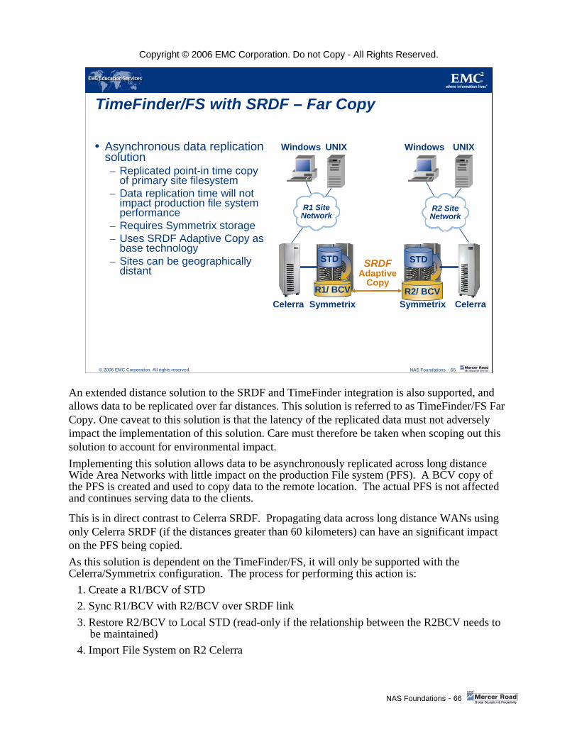
Copyright © 2006 EMC Corporation. Do not Copy - All Rights Reserved.
NAS Foundations - 66
© 2006 EMC Corporation. All rights reserved. NAS Foundations - 66
TimeFinder/FS with SRDF – Far Copy
Asynchronous data replication solution – Replicated point-in time copy
of primary site filesystem – Data replication time will not
impact production file system performance
– Requires Symmetrix storage– Uses SRDF Adaptive Copy as
base technology– Sites can be geographically
distant SRDF
AdaptiveCopy
Windows UNIX
Symmetrix CelerraCelerra SymmetrixR1/ BCV
STD
Windows UNIX
R2/ BCV
STD
R1 SiteNetwork
R2 SiteNetwork
An extended distance solution to the SRDF and TimeFinder integration is also supported, and allows data to be replicated over far distances. This solution is referred to as TimeFinder/FS Far Copy. One caveat to this solution is that the latency of the replicated data must not adversely impact the implementation of this solution. Care must therefore be taken when scoping out this solution to account for environmental impact. Implementing this solution allows data to be asynchronously replicated across long distance Wide Area Networks with little impact on the production File system (PFS). A BCV copy of the PFS is created and used to copy data to the remote location. The actual PFS is not affected and continues serving data to the clients.
This is in direct contrast to Celerra SRDF. Propagating data across long distance WANs using only Celerra SRDF (if the distances greater than 60 kilometers) can have an significant impact on the PFS being copied.As this solution is dependent on the TimeFinder/FS, it will only be supported with the Celerra/Symmetrix configuration. The process for performing this action is:
1. Create a R1/BCV of STD2. Sync R1/BCV with R2/BCV over SRDF link3. Restore R2/BCV to Local STD (read-only if the relationship between the R2BCV needs to
be maintained)4. Import File System on R2 Celerra

Copyright © 2006 EMC Corporation. Do not Copy - All Rights Reserved.
NAS Foundations - 67
© 2006 EMC Corporation. All rights reserved. NAS Foundations - 67
Celerra SRDF/ASRDF/A: Asynchronous Disaster Recovery
Delta Set-synchronized copies of volumes
Extended distances
NS Series/NSX Gateway
Network
SRDF/A
NS Series/NSXGateway
Celerra also integrates with the Symmetrix SRDF/A, asynchronous, product for extended distance support between the data centers. However, data replication in this case is asynchronous, and is therefore considered a Data Replication solution as opposed to Disaster Recovery.
SRDF/A—an asynchronous mechanism for extending the distance with manual failover and failback.
Asynchronous disaster recovery—Symmetrix SRDF/A technology connects a local NS Series/NSX Gateway and a remote NS Series/NSX Gateway to replicate the information over geographical distances. After a manual failover and recovery process, users gain access to file systems in the event that the local NS Series/NSX Gateway and/or the Symmetrixbecomes unavailable. The mode of operation supported with this solution is Active-PassiveWith active-passive (SRDF/S or SRDF/A) support, one NS Series/NSX Gateway provides active Data Mover access, while a second (remote) NS Series/NSX Gateway provides all Data Movers for failover.

Copyright © 2006 EMC Corporation. Do not Copy - All Rights Reserved.
NAS Foundations - 68
© 2006 EMC Corporation. All rights reserved. NAS Foundations - 68
Celerra Replicator - Data Replication
Celerra/Symmetrix Celerra NSX00
Windows
UNIX
Windows
UNIX
R1 SiteNetwork
R2 SiteNetwork
Production Filesystem
Primary SavVol
Secondary SavVol
IPNetwork
Secondary Filesystem
Log
• Point-in-time read-only file system copy over IP
• Production filesystem available during replication
• Only sends changed data over wire (after initial synchronization)
• One-way link for single target content distribution
• Asynchronous Data Recovery• Data recovery for CIFS data
Replication Process
The data replication solutions mentioned prior to this solution, with the exception of SnapSure, are restricted to the data transport mechanisms supported by the Symmetrixes.
Celerra Replicator is an IP protocol solution and can therefore be implemented over any established network infrastructure. However, as with Far Copy, care must therefore be taken when scoping out this solution to account for environmental impact, such as traffic latency and congestion.
Celerra Replicator Events:Manually synchronize production file system and secondary file system.Any changes to the production filesystems are recorded in the log - Log Changes.Transfer is triggered by special events. The trigger can be controlled by a user-defined policy or via an explicit request on the Control Station.Remote replication copies log changes to primary SavVol, and begins movement to secondary SavVol. An IP protocol transfer is set up with the remote replica for the newly updated set of SavVol blocks. While the transfer is in process, read/write activity on the PFS is not halted and a new log area is set up to track subsequent changes. Concurrently with the copy process, the newly created delta set is transferred to the secondary, over IP. In local replication (when the secondary Data Mover is in the same cabinet as the primary), no transfer is required. The delta set is accessible as a shared volume.Playback on Secondary: When the delta set arrives at the SavVol of the secondary and has been flagged as “valid”, the secondary will start to replay the blocks from its local SavVol, and apply the delta set to the SFS. This operation occurs transparently and with almost no interruption to SFS access.
The Replicator feature is able to support “data recovery” for both CIFS and NFS.
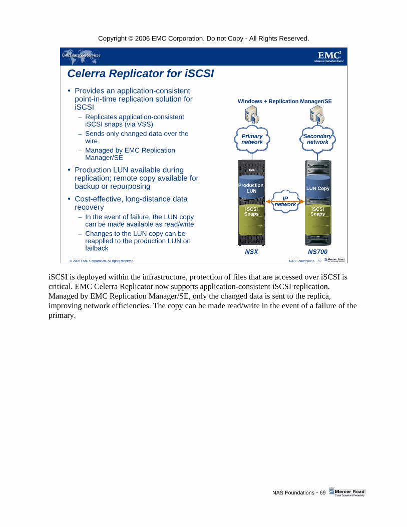
Copyright © 2006 EMC Corporation. Do not Copy - All Rights Reserved.
NAS Foundations - 69
© 2006 EMC Corporation. All rights reserved. NAS Foundations - 69
Celerra Replicator for iSCSIProvides an application-consistent point-in-time replication solution for iSCSI
– Replicates application-consistent iSCSI snaps (via VSS)
– Sends only changed data over the wire
– Managed by EMC Replication Manager/SE
Production LUN available during replication; remote copy available for backup or repurposing
Cost-effective, long-distance data recovery
– In the event of failure, the LUN copy can be made available as read/write
– Changes to the LUN copy can be reapplied to the production LUN on failback
Production LUN
NSX
IPnetwork
Windows + Replication Manager/SE
Secondarynetwork
Primarynetwork
4
NS700
LUN Copy
iSCSISnaps
iSCSISnaps
iSCSI is deployed within the infrastructure, protection of files that are accessed over iSCSI is critical. EMC Celerra Replicator now supports application-consistent iSCSI replication. Managed by EMC Replication Manager/SE, only the changed data is sent to the replica, improving network efficiencies. The copy can be made read/write in the event of a failure of the primary.
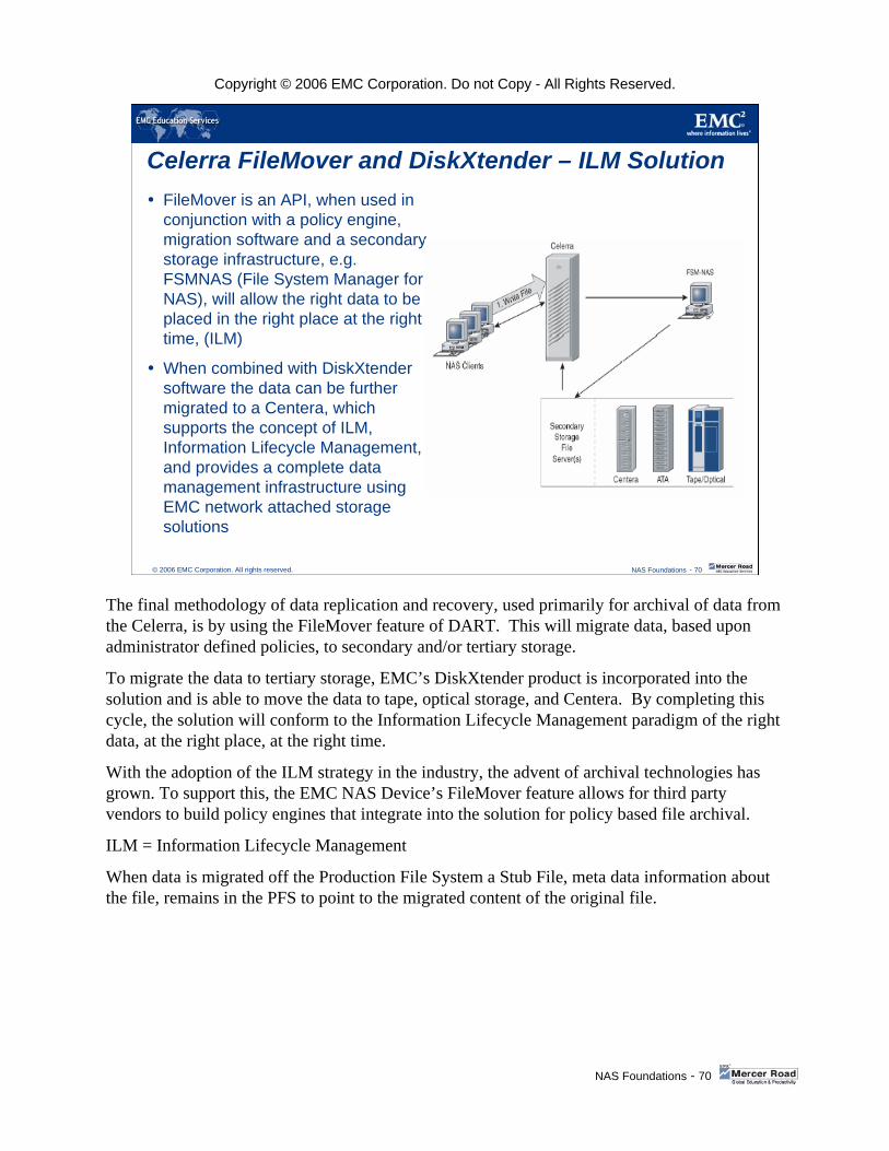
Copyright © 2006 EMC Corporation. Do not Copy - All Rights Reserved.
NAS Foundations - 70
© 2006 EMC Corporation. All rights reserved. NAS Foundations - 70
Celerra FileMover and DiskXtender – ILM SolutionFileMover is an API, when used in conjunction with a policy engine, migration software and a secondary storage infrastructure, e.g. FSMNAS (File System Manager for NAS), will allow the right data to be placed in the right place at the right time, (ILM)
When combined with DiskXtender software the data can be further migrated to a Centera, which supports the concept of ILM, Information Lifecycle Management, and provides a complete data management infrastructure using EMC network attached storage solutions
The final methodology of data replication and recovery, used primarily for archival of data from the Celerra, is by using the FileMover feature of DART. This will migrate data, based upon administrator defined policies, to secondary and/or tertiary storage.
To migrate the data to tertiary storage, EMC’s DiskXtender product is incorporated into the solution and is able to move the data to tape, optical storage, and Centera. By completing this cycle, the solution will conform to the Information Lifecycle Management paradigm of the right data, at the right place, at the right time.
With the adoption of the ILM strategy in the industry, the advent of archival technologies has grown. To support this, the EMC NAS Device’s FileMover feature allows for third party vendors to build policy engines that integrate into the solution for policy based file archival.
ILM = Information Lifecycle Management
When data is migrated off the Production File System a Stub File, meta data information about the file, remains in the PFS to point to the migrated content of the original file.

Copyright © 2006 EMC Corporation. Do not Copy - All Rights Reserved.
NAS Foundations - 71
© 2006 EMC Corporation. All rights reserved. NAS Foundations - 71
Celerra Family
BACKUP AND RESTORE OPTIONS
The final solution that we will be briefly reviewing is the most important concept of data backup and recovery.

Copyright © 2006 EMC Corporation. Do not Copy - All Rights Reserved.
NAS Foundations - 72
© 2006 EMC Corporation. All rights reserved.
Backup and Restore Options
NetworkNetworkBackupBackup
Most backup utilitiesNFS / CIFS mounts over the client network or separate sub-network
Network
Celerra
DATA
NetWorker Tape
NDMP NDMP BackupBackup(LAN(LAN--lessless
local backup)local backup)
VERITAS NetBackupEMC NetworkerCommVault GalaxyHP OmniBackAtempo Time Navigator Tape
Celerra
Symmetrixor CLARiiON
Network
Data
NetWorker
NDMP2DNDMP2DBackupBackup
NDMP enabled backup utilitiesBackup local Celerra data to specially configured disks within the array
Network
CelerraNetWorker
NAS is a fast growing market. Many NAS implementations have mission-critical data availability requirements, and this is what Celerra does best. Fast and efficient backup and restore is an absolute requirement.
There are a number of options as far as backup and restore are concerned. This slide depicts some of these options.
Network backups entail simply mounting the filesystems across the network and backing up to the backup server. EMC Data Manager, and most backup utilities, support this option. EDM will also preserve the bi-lingual information (CIFS and NFS) with network backups.
NDMP backups only use the LAN for control information (LAN-less), and the data is transferred to the local backup device. EDM, VERITAS NetBackup, EMC Networker, CommVault Galaxy, HP OmniBack, and Atempo Time Navigator support Celerra NDMP backups. NDMP backups preserve the bi-lingual file information.

Copyright © 2006 EMC Corporation. Do not Copy - All Rights Reserved.
NAS Foundations - 73
© 2006 EMC Corporation. All rights reserved. NAS Foundations - 73
Celerra Network BackupThird-party backup products– CIFS access through shares– NFS access through mounts Network
CLARiiONor
Symmetrix
Celerra
Tape Library
Data FlowControl Information Flow
Network backups utilize a backup server that mounts the remote filesystems, and transfers them to tape. The data path includes the Celerra Data Mover, the network, and the backup server.
Most third-party backup products support CIFS network backups through remote file shares, and NFS network backups using remote file mounts.
Third-party backups should not be used for multi-protocol files. For example, if they are backed up over a CIFS share, they will lose any NFS attributes and permissions upon restoration.
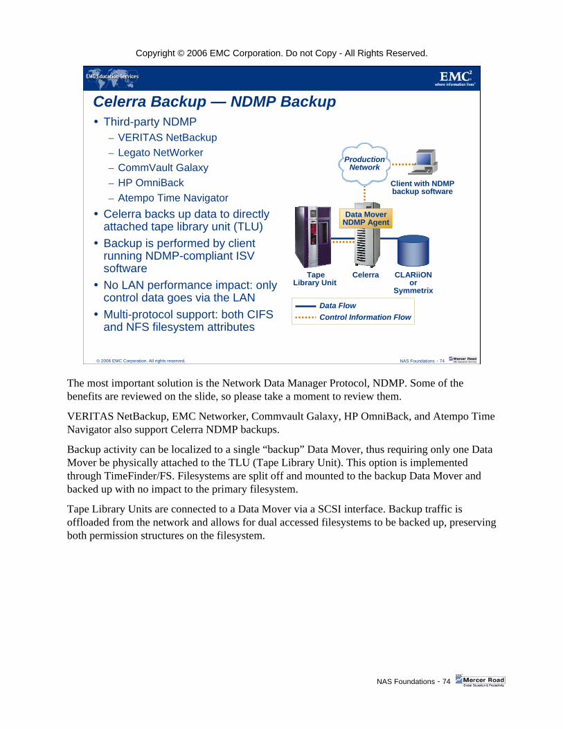
Copyright © 2006 EMC Corporation. Do not Copy - All Rights Reserved.
NAS Foundations - 74
© 2006 EMC Corporation. All rights reserved. NAS Foundations - 74
Celerra Backup — NDMP BackupThird-party NDMP– VERITAS NetBackup– Legato NetWorker– CommVault Galaxy– HP OmniBack– Atempo Time Navigator
Celerra backs up data to directly attached tape library unit (TLU)Backup is performed by client running NDMP-compliant ISV softwareNo LAN performance impact: only control data goes via the LANMulti-protocol support: both CIFS and NFS filesystem attributes
Data FlowControl Information Flow
Client with NDMP backup software
ProductionNetwork
TapeLibrary Unit
Celerra
Data MoverNDMP Agent
CLARiiONor
Symmetrix
The most important solution is the Network Data Manager Protocol, NDMP. Some of the benefits are reviewed on the slide, so please take a moment to review them.
VERITAS NetBackup, EMC Networker, Commvault Galaxy, HP OmniBack, and Atempo Time Navigator also support Celerra NDMP backups.
Backup activity can be localized to a single “backup” Data Mover, thus requiring only one Data Mover be physically attached to the TLU (Tape Library Unit). This option is implemented through TimeFinder/FS. Filesystems are split off and mounted to the backup Data Mover and backed up with no impact to the primary filesystem.
Tape Library Units are connected to a Data Mover via a SCSI interface. Backup traffic is offloaded from the network and allows for dual accessed filesystems to be backed up, preserving both permission structures on the filesystem.

Copyright © 2006 EMC Corporation. Do not Copy - All Rights Reserved.
NAS Foundations - 75
© 2006 EMC Corporation. All rights reserved. NAS Foundations - 75
NDMP2D – Network Data Management Protocol to Disk
This feature allows for the creation of a tape target on a Celerra using either Fibre Channel or ATA drives
Multi-protocol support: both CIFS and NFS filesystem attributes
Network
Celerra
NetWorker
PFS
NDMP2D
Meta Data
NDMP Control
NDMP2D is the creation of emulated tape devices and cartridges on either ATA or fiber drives configured in a RAID3 4+1 or 8+1 grouping, to allow for the NDMP backup of Celerra data. This feature is supported in DART v5.4 and later versions.
This feature utilizes ATA storage with a RAID 3 configuration on either 4+1 or 8+1 devices, for standard archival. However, fiber channel drives could be used if enhanced performance requirements are needed.
It allows backups to be performed to tape drive, and cartridge emulations created on the NAS array, via NDMP enabled backup software..
This allows for greatly enhanced recovery options and granularity, dependant upon the feature set of the backup software.
(PFS = Production File System)

Copyright © 2006 EMC Corporation. Do not Copy - All Rights Reserved.
NAS Foundations - 76
© 2006 EMC Corporation. All rights reserved. NAS Foundations - 76
Definition of NDMP2D
A software-based tape target that resides on a Data Mover– Emulates a physical tape library unit (TLU)
Allows compatibility between NDMP & disk-based storage– Backup software responsible for managing TLUs cannot distinguish
between NDMP2D and a physical TLU.
This emulation allows NDMP to work with disk storage, rather than the tape storage for which it was designed.
NDMP2D can be configured and operated from NDMP Client S/W as if it were a physical TLU attached to a Data Mover
NDMP2D is a filesystem-based storage sub-system that emulates SCSI Tape Library Units (TLUs) and tape drives.
Applications communicating with NDMP2D get the impression of communicating with a standard commercial TLU.
NDMP2D will maximize the attractiveness of NDMP-based PAX, VBB, VLC (aka tape silvering) and other EMC backup products.
NDMP2D could eliminate the need for physical tape drives and provide a single, centralized data repository.

Copyright © 2006 EMC Corporation. Do not Copy - All Rights Reserved.
NAS Foundations - 77
© 2006 EMC Corporation. All rights reserved. NAS Foundations - 77
Course SummaryKey points covered in this course:
The concepts and value of Network Attached Storage
Environmental aspects of NAS
EMC NAS platforms and their differences
Key Celerra software features
The Celerra Management software offerings
Key Windows specific options with respect to EMC NAS environments
NAS Business Continuity and Replication options with respect to the various EMC NAS platforms
Key NAS Backup and Recovery options
These are the key points covered in this training. Please take a moment to review them.
This concludes the training. In order to receive credit for this course, please proceed to the Course Completion slide to update your transcript and access the Assessment.