guidelines for operation on fuels with less than 0.1% sulphur
TRANSCRIPT

Guidelines for Operation on Fuelswith less than 0.1% Sulphur


Guidelines for Operation on Fuels with less than 0.1% Sulphur 3
Contents
1. Low-BN cylinder oils ................................................................................6
2. Standard of marine fuels: ISO 8217-2012 .................................................9
3. New fuels with less than 0.1% S ..............................................................9
4. Viscosity ............................................................................................... 10
5. Fuel pump pressure ............................................................................... 13
6. Lubricity ................................................................................................. 14
7. Cat-fines (Al+Si) ..................................................................................... 14
8. Fuel temperature: pour point ................................................................. 16
9. Compatibility between fuels .................................................................... 16
10. Fuel change-over procedures ............................................................... 17
11. Low-sulphur biofuel .............................................................................. 19
12. Summary ............................................................................................. 20
Appendix ................................................................................................... 20

Guidelines for Operation on Fuels with less than 0.1% Sulphur 5
Guidelines for Operation on Fuels with less than 0.1% Sulphur
Introduction
This paper is a guideline for owners,
operators and crews on how to prepare
for the changes in fuel characteristics
and how to operate in compliance with
the new sulphur limits in sulphur emis-
sion control areas (SECA) as of 1 Janu-
ary 2015. The SECAs currently includ-
ed are the Baltic Sea, The North Sea,
the English Channel and waters within
200 nautical miles from the coast of
USA, the coastal waters around Puerto
Rico and the U.S. Virgin Islands (the US
Caribbean ECA) and Canada.
The sulphur (S) limit will decrease from
max. 1.0% S to max. 0.1% S. This
means that in order to comply with the
legislation, operators will have to use
either a fuel with less than 0.1% sul-
phur, e.g. distillate, other fuels with less
than 0.1% S, or install a scrubber.
MAN Diesel & Turbo recommends fuels
with a viscosity of min. 2 cSt at engine
inlet and change-over to low-BN cylin-
der lube oils immediately when chang-
ing over to fuels with less than 0.1% S.
MAN B&W two-stroke engines and
Holeby GenSets are optimised to oper-
ate on heavy fuel oil (HFO).
However, fuels with less than 0.1% S
can be used when appropriate actions
are taken:
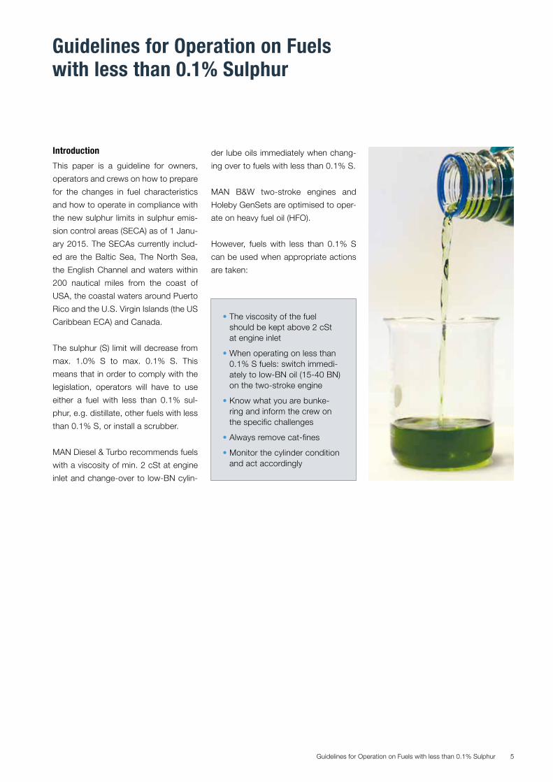
• The viscosity of the fuel should be kept above 2 cSt at engine inlet
• When operating on less than 0.1% S fuels: switch immedi-ately to low-BN oil (15-40 BN) on the two-stroke engine
• Know what you are bunke- ring and inform the crew on the specific challenges
• Always remove cat-fines
• Monitor the cylinder condition and act accordingly
Guidelines for Operation on Fuels with less than 0.1% Sulphur6
Engine type Two-strokeengines
≤ Mark 7 ≥ Mark 8
YesNo Basedesign
15-40 BN oilLow S fuel
High S fuel
15-40 BN oil 15-40 BN oil
70-100 BN oil 100 BN oil70 BN oil
Engine design
Cylinderlube oil
Optimised for improvedfuel consumption:Part load optimised andderated engines
1. Low-BN cylinder oils
Until now, marine low speed engines
and their lubricants have been opti-
mised for operation on heavy fuel oil
(HFO) with a high sulphur (S) content.
During combustion, the S is converted
to sulphur trioxide (SO3). In combination
with water from the combustion and the
scavenge air, SO3 forms sulphuric acid
(H2SO4). When the liner temperature
drops below the dew point of sulphu-
ric acid and water, a corrosive mixture
condenses on the liner wall. The high-
alkaline lubricants (high-BN oils) neu-
tralise the acid and prevent corrosion of
piston rings and cylinder liner surfaces.
When operating on fuels with less than
0.1 % S, such as distillates, ultra-low-
sulphur fuel oil (ULSFO) with less than
0.1% S, LNG, methanol, ethane and
LPG, only small amounts of sulphu-
ric acid are formed in the combustion
chamber. The cylinder lube oil addi-
tives are then not used for the designed
purpose and they tend to build up as
deposits. These deposits may disturb
the lube oil film and obstruct the pis-
ton ring movement, which could lead to
micro-seizures on the piston rings and
liner and increase the risk of scuffing.
Deposit formation and the total lack
of corrosion increase the risk of bore-
polishing, which could also lead to in-
creased wear and scuffing. For engines
operating continuously on fuels with
less than 0.1% S, we recommend to
install piston rings with cermet coating
on all four rings to reduce the risk of
seizures and scuffing.
Lubrication strategy
Complications caused by deposit
build-up can be avoided by using cyl-
inder lube oils with a low amount of
deposit-forming additives and good
detergency properties (low-BN oils)
and by operating at the lowest recom-
mended cylinder lube oil feed rate. The
feed rate should be decreased to the
minimum feed rate specified in our lat-
est service letters.
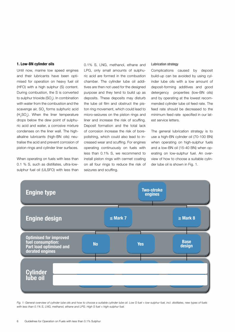
The general lubrication strategy is to
use a high-BN cylinder oil (70-100 BN)
when operating on high-sulphur fuels
and a low-BN oil (15-40 BN) when op-
erating on low-sulphur fuel. An over-
view of how to choose a suitable cylin-
der lube oil is shown in Fig. 1.
Fig. 1: General overview of cylinder lube oils and how to choose a suitable cylinder lube oil. Low S fuel = low-sulphur fuel, incl. distillates, new types of fuels with less than 0.1% S, LNG, methanol, ethane and LPG. High S fuel = high-sulphur fuel.

Guidelines for Operation on Fuels with less than 0.1% Sulphur 7
Deck
Filling pipe
Cylinder oil service tank
Heater with set point of 45 °C
Heating cable engine builder supply
Filling pipe
Internal connection changes both at the same time
Filling pipe
Storage tank for low BN cylinder oil
Filling pipe Cylinder oil service tank
Small box for heater element
Level alarm
Storage tank for high BNcylinder oli
Min
. 30
00m
m
Terminal box El. connection
LS AL8212
Min
. 20
00m
mHIGHBN
LOW BN
100 101
TI
Table 1 Fuel S applications for low-BN cylinder oils
When switching to fuels with less than
0.1% S, we recommend switching to a
low-BN cylinder oil at the same time.
We do not recommend the use of a
high-BN cylinder oil when running on
fuels with less than 0.1% S. This recom-
mendation is valid for all engine types
and Mark numbers, and for all lubri-
cator types: electronic (ME and Alpha
Lubricator) and mechanical (e.g. Hans
Jensen), see also our service letters on
cylinder lubrication, SL2014-587 (elec-
tronic lubricators) and SL2012-553
(mechanical lubricators).
To support this, we have for many years
recommended to install two service
tanks, one for low-BN oil and one for
high-BN oil (Fig. 2).
There are low-BN cylinder lube oils with
different BN levels on the market today.
Currently, there are three different low-
BN levels: 17, 25 and 40 BN. However,
development continues and in the fu-
ture there could be oils with other BN
levels. Good performance of the low-
BN oil is the most important factor.
As the neutralising capacity of these oils
varies with the BN, the max. fuel S con-
tent also varies. We recommend using
them for fuels within the below-speci-
fied fuel S content interval (Table 1).
When using the low-BN oils for higher
sulphur fuels (e.g. 0.5% S fuel) we rec-
ommend dosing the oils at higher feed
rates as according to the normal ACC
or feed rate factor (FRF) strategy for
electronic lubricators (see Appendix or
CLO Advisor).
Fig. 2: Recommendation for cylinder lubrication system for ME engines. Similar system should be installed on MC engines using the Alpha Lubricator or mechanical lubricators
Cylinder lube oil BN Min. % S fuel Max. % S fuel
15-24 0 0.5
25-34 0 1.0
35-40 0 1.5
Guidelines for Operation on Fuels with less than 0.1% Sulphur8
• Recommendations are valid for all engine types and Mark numbers
• Use low-BN oil (15-40 BN) when operating on fuels < 0.1% S
• When switching to < 0.1% S fuels: switch immediately to low-BN oil
• Operation on < 0.1% S fuels: optimise the feed rate towards
Summary 1: low-BN cylinder oils
minimum (0.6-0.7 g/kWh) for electronic lubricators. Use the fixed feed rate for mechanical lubricators
• Two service tanks: one for high-BN oil and one for low-BN oil
• Monitor the cylinder condition and act accordingly
We expect that the lowest BN oils (17
and 25 BN) will perform best, both in
short- and long-term operation, on fu-
els with less than 0.1% S. However, 40
BN oils may perform satisfactorily for a
shorter time on such fuels, and we rec-
ommend a maximum operation time of
1-2 weeks on 40 BN oils, see Table 2.
Used oil samples (also called drain
oil or scrape down oil) taken from the
engine through the scavenge bottom
drain can be used for cylinder condi-
tion evaluation. Drain oil analysis can
show whether the cylinder condition
is within the normal range or whether
action must be taken, e.g. lowering the
feed rate towards minimum dosage or
removing cat-fines from the fuel, see
latest service letter or the CLO Advisor.
Operation on fuels with less than 0.1%
S induces less corrosion on the liners,
so we expect normal wear values for
iron (Fe) to be in the range of 50-100
ppm and the remaining BN to be 5-10
BN less than the original BN value.
Guiding values for alarm levels are list-
ed in Table 3.
Table 4 shows examples of low-BN cyl-
inder oils presently available in the inter-
national market. High- and low-BN oils
are listed in “Oils for Marine Two-Stroke
Engines” (case no. 50921-2014).
Cylinder lube oil BN Recommended time of operation on fuels < 0.1% S
15-30 Short and long term service
30-40 Less than 1-2 weeks
Table 2 Recommended time of operation on fuels with less than 0.1% S
Cylinder lube oil BN Scavenge drain oil – Guiding values
Remaining BN Fe, ppm
15-24 > 5-10 < 100-200 depending on engine type
25-34 > 5-15 < 100-200 depending on engine type
35-40 > 10-20 < 100-200 depending on engine type
Table 3 Guiding alarm levels for scavenge drain oils for fuels with less than 0.1% S
Oil company Oil name BN level
Aegean Alfacylo 540 LS 40
Castrol Cyltech 40SX 40
Chevron Taro Special HT LF 25
Taro Special HT LS 40 40
ExxonMobil Mobilgard 525 25
Gulf Oil Marine GulfSea Cylcare ECA 50 17
GulfSea Cylcare DCA 5040H 40
Indian Oil Corp. Servo Marine LB 1750 17
JX Nippon Oil & Energy Marine C405 40
Lukoil Navigo 40 MCL 40
Shell Alexia S3 25
Sinopec Marine Cylinder Oil 5040 40
Total Talusia LS 25 25
Talusia LS40 40
Table 4 Examples of low-BN cylinder oils on the international market
Guidelines for Operation on Fuels with less than 0.1% Sulphur 9
2. Standard of marine fuels: ISO 8217-2012
The current ISO 8217-2012 standard
for marine fuels specifies three different
distillate grades (DM) and a number of
residual grades (RM). Table 5 shows the
key characteristics for fuels which may
fulfil the maximum 0.1% sulphur limit.
3. New fuels with less than 0.1% S
New types of 0.1% S fuels are entering
the market in response to the 0.1% S
SECA limit. These new fuel types are
usually referred to as ultra-low-sulphur
fuel oils (ULSFO), which are usually not
traditional distillates, but blended prod-
ucts or products from refinery streams
that have not previously been utilised
extensively in marine fuels. MAN Diesel
& Turbo expects that these fuels are
well-suited for MAN B&W two-stroke
engines as well as Holeby GenSets.
However, as always, it is important
to read and act on the fuel suppliers’
recommendations, manuals and best
practise sheets to ensure that the fuel
can be used safely and efficiently.
Some of the fuels are in the ISO 8217
DM-range and some in the RM-grades.
Key characteristics Unit Limit DMA DMZ DMB RMA 10 RMB 30 RMD 80
Density at 15°C kg/m³ Max 890 890 900 920 960 975
Viscosity at 40°C mm²/s (cSt) Min. 2.00 3.00 2.00 - - -
Max. 6.0 6.0 11.0 - - -
Viscosity at 50°C mm²/s (cSt) Max. - - - 10.0 30.0 80.0
Sulphur % m/m Max. 1.50 1.50 2.00 max. 0.1% in SECA
Flash point °C Min. 60 60 60 60 60 60
Pour point (winter) °C Max. -6.0 -6.0 0.0 0 0 30
Acid number mg KOH/g Max. 0.5 0.5 0.5 2.5 2.5 2.5
Al+Si ppm m/m Max. - - - 25 40 40
Lubricity µm Max. 520 520 520 - - -
Table 5 Key characteristics of fuels in the ISO standard for marine fuels, ISO 8217-2012
Guidelines for Operation on Fuels with less than 0.1% Sulphur10
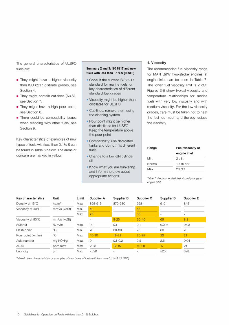
4. Viscosity
The recommended fuel viscosity range
for MAN B&W two-stroke engines at
engine inlet can be seen in Table 7.
The lower fuel viscosity limit is 2 cSt.
Figures 3-5 show typical viscosity and
temperature relationships for marine
fuels with very low viscosity and with
medium viscosity. For the low viscosity
grades, care must be taken not to heat
the fuel too much and thereby reduce
the viscosity.
The general characteristics of ULSFO
fuels are:
� They might have a higher viscosity
than ISO 8217 distillate grades, see
Section 4.
� They might contain cat-fines (Al+Si),
see Section 7.
� They might have a high pour point,
see Section 8.
� There could be compatibility issues
when blending with other fuels, see
Section 9.
Key characteristics of examples of new
types of fuels with less than 0.1% S can
be found in Table 6 below. The areas of
concern are marked in yellow.
• Consult the current ISO 8217 standard for marine fuels for key characteristics of different standard fuel grades
• Viscosity might be higher than distillates for ULSFO
• Cat-fines: remove them using the cleaning system
• Pour point might be higher than distillates for ULSFO. Keep the temperature above the pour point
• Compatibility: use dedicated tanks and do not mix different fuels
• Change to a low-BN cylinder oil
• Know what you are bunkering and inform the crew about appropriate actions
Summary 2 and 3: ISO 8217 and new fuels with less than 0.1% S (ULSFO)
Key characteristics Unit Limit Supplier A Supplier B Supplier C Supplier D Supplier E
Density at 15°C kg/m³ Max 895-915 870-930 928 910 845
Viscosity at 40°C
mm²/s (=cSt)
Min. 40 - 45 - -
Max. 75 65 - -
Viscosity at 50°C mm²/s (=cSt) - 8-25 30-40 65 8.8
Sulphur % m/m Max. 0.1 0.1 0.1 0.095 0.03
Flash point °C Min. 70 60-80 70 60 70
Pour point (winter) °C Max. 15-30 18-21 20-25 20 21
Acid number mg KOH/g Max. 0.1 0.1-0.2 2.5 2.5 0.04
Al+Si ppm m/m Max. <0.3 12-15 10-20 17 <1
Lubricity µm Max. <320 - - 520 328
Table 6 Key characteristics of examples of new types of fuels with less than 0.1 % S (ULSFO)
Range Fuel viscosity at
engine inlet
Min. 2 cSt
Normal 10-15 cSt
Max. 20 cSt
Table 7 Recommended fuel viscosity range at engine inlet
Guidelines for Operation on Fuels with less than 0.1% Sulphur 11
Kin. viscosity, cSt
Fuel temperature, °C
12
10
8
6
4
2
00 20 40 60 80 100 120
2 cSt @ 40°C
3 cSt @ 40°C
4 cSt @ 40°C
5 cSt @ 40°C
6 cSt @ 40°C
Fig. 3: Temperature – viscosity relationship for very low viscosity fuels
Fig. 4: Temperature – viscosity relationship for low-medium viscosity fuels
2 cSt @ 40°C
10 cSt @ 50°C
30 cSt @ 50°C
50 cSt @ 50°C
80 cSt @ 50°C
Kin. viscosity, cSt
Fuel temperature, °C
600
500
400
300
200
100
00 20 40 60 80 100 120
80Kin. viscosity, cSt
Temperature, °C
70
60
50
40
30
20
10
00 20 40 60 80 100 120
2 cSt @ 40°C
10 cSt @ 50°C
30 cSt @ 50°C
50 cSt @ 50°C
80 cSt @ 50°C
The external fuel systems (supply and
circulating systems) have a varying ef-
fect on the heating of the fuel and,
thereby, the viscosity of the fuel when
it reaches engine inlet. Today, external
fuel systems on-board are often de-
signed to have an optimum operation
on HFO, which means that the tem-
perature is kept high. When running on
low-viscosity fuels, the temperature of
the fuel system must be as low as pos-
sible to ensure a suitable viscosity at
engine inlet.
Low-viscosity fuels challenge the func-
tion of the fuel pump in three ways:
1. Breakdown of the hydrodynamic oil
film, which could result in seizures.
2. Insufficient injection pressure, which
results in difficulties during start-up
and low-load operation.
3. Insufficient fuel index margin, which
limits acceleration.
Many factors influence the viscosity
tolerance during start-up and low-load
operation:
� Engine condition and maintenance
� Fuel pump wear
� Engine adjustment (mainly starting
index)
� Actual fuel temperature in the fuel
system.
Fig. 5: Temperature – viscosity relationship for low-medium viscosity fuels
Guidelines for Operation on Fuels with less than 0.1% Sulphur12
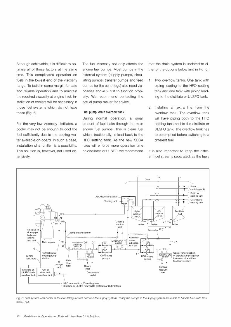
Venting tank
Aut. deaerating valve
Distillate fuel
Low-sulphur
HFO
High-sulphur
HFO
D *)
D *)
d *)
D *)
Fromcentrifuges #)
Deck
Overflow tosettling tank
Drain tosettling tank
HFO supplypumps
Air cooler
Coolingmedium
inlet
Cooler for protection of supply pumps against too warm oil and thus too low viscosity
Coolingmedium
inlet
Temperature sensor
Circulatingpumps
Pre-heater
Steaminlet
Condensateoutlet
MDO/MGO **)cooler
MDO/MGO cooler
Overflowvalveadjustedto 4 bar
Main engine
32 mmnom. bore
F
X
AF
a)a)
Fuel oildrain tank
overflow tank
Distillate or ULSFO drain,overflow tank
BD
HFO returned to HFO settling tank Distillate or ULSFO returned to Distillate or ULSFO tank
AD
b)
To freshwatercooling pumpstation
Tosludgetank
Full-flowfilter
No valve indrain pipebetweenengineand tank
Viscositysensor
TITI
The fuel viscosity not only affects the
engine fuel pumps. Most pumps in the
external system (supply pumps, circu-
lating pumps, transfer pumps and feed
pumps for the centrifuge) also need vis-
cosities above 2 cSt to function prop-
erly. We recommend contacting the
actual pump maker for advice.
Fuel pump: drain overflow tank
During normal operation, a small
amount of fuel leaks through the main
engine fuel pumps. This is clean fuel
which, traditionally, is lead back to the
HFO settling tank. As the new SECA
rules will enforce more operation time
on distillates or ULSFO, we recommend
Fig. 6: Fuel system with cooler in the circulating system and also the supply system. Today the pumps in the supply system are made to handle fuels with less than 2 cSt.
Although achievable, it is difficult to op-
timise all of these factors at the same
time. This complicates operation on
fuels in the lowest end of the viscosity
range. To build in some margin for safe
and reliable operation and to maintain
the required viscosity at engine inlet, in-
stallation of coolers will be necessary in
those fuel systems which do not have
these (Fig. 6).
For the very low viscosity distillates, a
cooler may not be enough to cool the
fuel sufficiently due to the cooling wa-
ter available on-board. In such a case,
installation of a ‘chiller’ is a possibility.
This solution is, however, not used ex-
tensively.
that the drain system is updated to ei-
ther of the options below and in Fig. 6:
1. Two overflow tanks. One tank with
piping leading to the HFO settling
tank and one tank with piping lead-
ing to the distillate or ULSFO tank.
2. Installing an extra line from the
overflow tank. The overflow tank
will have piping both to the HFO
settling tank and to the distillate or
ULSFO tank. The overflow tank has
to be emptied before switching to a
different fuel.
It is also important to keep the differ-
ent fuel streams separated, as the fuels
Guidelines for Operation on Fuels with less than 0.1% Sulphur 13
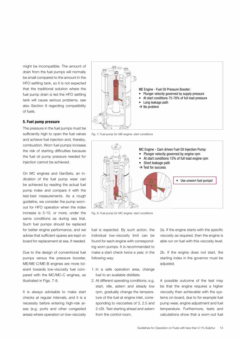
ME Engine - Fuel Oil Pressure Booster:• Plunger velocity governed by supply pressure• At start conditions 75-78% of full load pressure• Long leakage path No problem
MC Engine - Cam driven Fuel Oil Injection Pump:• Plunger velocity governed by engine rpm• At start conditions 15% of full load engine rpm• Short leakage path Test for success
• Use unworn fuel pumps!
ME engine - Fuel Oil Pressure Booster:• Plunger velocity governed by supply pressure• At start conditions 75-78% of full load pressure• Long leakage path No problem
fuel is expected. By such action, the
individual low-viscosity limit can be
found for each engine with correspond-
ing worn pumps. It is recommended to
make a start check twice a year, in the
following way:
1. In a safe operation area, change
fuel to an available distillate.
2. At different operating conditions, e.g.
start, idle, astern and steady low
rpm, gradually change the tempera-
ture of the fuel at engine inlet, corre-
sponding to viscosities of 3, 2.5 and
2 cSt. Test starting ahead and astern
from the control room.
might be incompatible. The amount of
drain from the fuel pumps will normally
be small compared to the amount in the
HFO settling tank, so it is not expected
that the traditional solution where the
fuel pump drain is led the HFO settling
tank will cause serious problems, see
also Section 9 regarding compatibility
of fuels.
5. Fuel pump pressure
The pressure in the fuel pumps must be
sufficiently high to open the fuel valves
and achieve fuel injection and, thereby,
combustion. Worn fuel pumps increase
the risk of starting difficulties because
the fuel oil pump pressure needed for
injection cannot be achieved.
On MC engines and GenSets, an in-
dication of the fuel pump wear can
be achieved by reading the actual fuel
pump index and compare it with the
test-bed measurements. As a rough
guideline, we consider the pump worn-
out for HFO operation when the index
increase is 5-10, or more, under the
same conditions as during sea trial.
Such fuel pumps should be replaced
for better engine performance, and we
advise that sufficient spares are kept on
board for replacement at sea, if needed.
Due to the design of conventional fuel
pumps versus the pressure booster,
ME/ME-C/ME-B engines are more tol-
erant towards low-viscosity fuel com-
pared with the MC/MC-C engines, as
illustrated in Figs. 7-8.
It is always advisable to make start
checks at regular intervals, and it is a
necessity before entering high-risk ar-
eas (e.g. ports and other congested
areas) where operation on low-viscosity
Fig. 7: Fuel pump for ME-engine: start conditions
Fig. 8: Fuel pump for MC engine: start conditions
2a. If the engine starts with the specific
viscosity as required, then the engine is
able run on fuel with this viscosity level.
2b. If the engine does not start, the
starting index in the governor must be
adjusted.
A possible outcome of the test may
be that the engine requires a higher
viscosity than achievable with the sys-
tems on-board, due to for example fuel
pump wear, engine adjustment and fuel
temperature. Furthermore, tests and
calculations show that a worn-out fuel
MC Engine - Cam driven Fuel Oil Injection Pump:• Plunger velocity governed by engine rpm• At start conditions 15% of full load engine rpm• Short leakage path Test for success
• Use unworn fuel pumps!
MC Engine - Cam driven Fuel Oil Injection Pump:• Plunger velocity governed by engine rpm• At start conditions 15% of full load engine rpm• Short leakage path Test for success
• Use unworn fuel pumps!
Guidelines for Operation on Fuels with less than 0.1% Sulphur14
7. Cat-fines (Al+Si)
As in heavy fuel oil (HFO), cat-fines may
also be found in fuels with less than
0.1% S (ULSFO, see Section 3). Cat-
fines are small, very hard particles from
the refining process. They can wear
the engine fast, and it is highly recom-
mended to use the fuel cleaning and
condition system in an adequate man-
ner to clean the fuel and remove the
cat-fines.
The traditional diesel systems on board
are dimensioned to operate on low-vis-
cosity fuel at rather low temperatures.
Compared to HFO cleaning systems,
the separator and preheater are smaller
dimensioned and the electrical equip-
ment might not be certified safe equip-
ment. As the viscosity of distillates and
ULSFO is very different, it is important
to pay attention to the recommended
temperature for the different fuel types
during the cleaning process, see Table
8.
The cleaning systems must be de-
signed for operation at the higher tem-
peratures and lower recommended
flow. Too low a temperature and too
high a flow through the separators dur-
ing cleaning will result in insufficient re-
moval of water, cat-fines, sludge and
other contaminants (Fig. 9).
The cat-fine level should be kept as low
as possible before the engine inlet, and
the maximum level is 10 ppm (Fig. 10).
Fuel type Min. fuel temperature in the separator
Distillates 40-50°C
ULSFO 98°C
HFO 98°C or higher
Table 8 Recommended fuel temperature for cleaning in the separator
pump for an MC-engine cannot start on
a fuel with a viscosity of 2 cSt.
6. Lubricity
The refinery processes which remove
sulphur from the oil also impact the
components which give the fuel its
lubricity. Most refiners add lubricity-
enhancing additives to distillates. Too
little lubricity may result in fuel pump
seizures. However, MAN Diesel & Turbo
does not regard the lubricity of the fuel
as a major issue. We have not yet heard
of and/or experienced any failure due
to the lubricity of the fuel. Our research
tests show that we cannot provoke a
failure due to lack of lubricity. We do
not usually see the need to use lubricity
modifiers. However, if there is a genu-
ine challenge, then a lubricity modifier
might solve the issue.
MAN Diesel & Turbo has adopted the
ISO 8217-2012 lubricity limit: HFRR
(high-frequency reciprocating rig) wear
scar limit: max 520 µm. We recom-
mend testing the lubricity before us-
ing fuels with less than 0.05% sulphur.
Independent fuel laboratories can test
lubricity according to ISO12156-1.
• Know what is bunkered
• The viscosity of the fuel should be kept above 2 cSt at engine inlet
• Fuel pumps should be in adequate condition: If not, starting problems could occur, especially on MC engines and GenSets
• Adequate fuel system: check if the necessary cooling equip-ment is working/installed
Summary 4 and 5: viscosity and fuel pump pressure

Guidelines for Operation on Fuels with less than 0.1% Sulphur 15
Mass concentration
� Low temperature� High flow
Particle diameter, μm0 2 4 6 8 10
Mass concentration
Separator Operation
� High temperature� Low flow
Particle diameter, μm0 2 4 6 8 10
In
Out
In
Out
AI + Si
Two stroke (+ small 4S)
Sample position
>15 ppm
10 ppm
<5 ppm
Fig. 9: Separator operations at different parameters. Note the increased cleaning at high temperature and low flow.
Fig. 10: Recommended maximum content of cat-fines in fuel entering the engine
Guidelines for Operation on Fuels with less than 0.1% Sulphur16
Temp. > cloud pointand pour point
Temp. < cloud point Temp. < pour point
Heat
er
Not compatible fuels Compatible fuels
Fig. 11: Photos of a distillate sample at different temperatures
Fig. 14: Spot test: photos of mixture of two different fuels on filter paper (courtesy Chevron)
Fig. 12: Schematic example of tank configuration: re-circulating the fuel and heating it by an external heater
Fig. 13: Waxy precipitations in a fuel sample
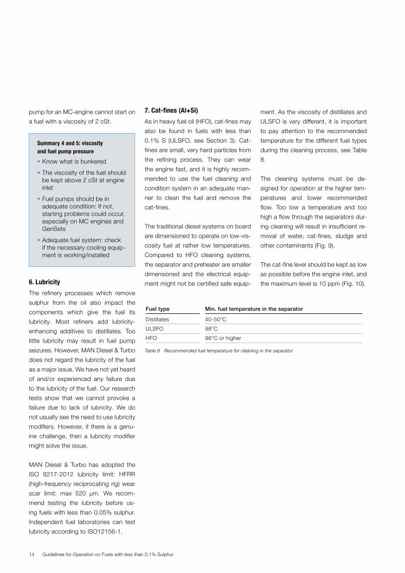
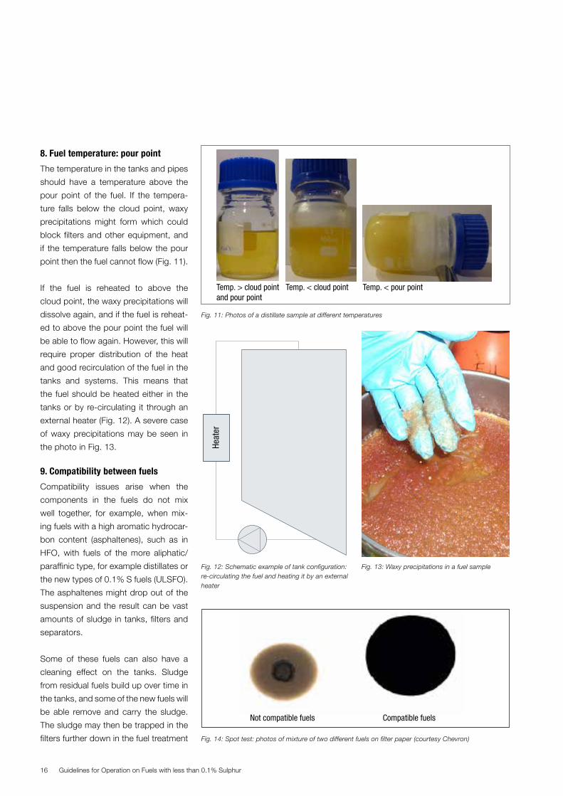
8. Fuel temperature: pour point
The temperature in the tanks and pipes
should have a temperature above the
pour point of the fuel. If the tempera-
ture falls below the cloud point, waxy
precipitations might form which could
block filters and other equipment, and
if the temperature falls below the pour
point then the fuel cannot flow (Fig. 11).
If the fuel is reheated to above the
cloud point, the waxy precipitations will
dissolve again, and if the fuel is reheat-
ed to above the pour point the fuel will
be able to flow again. However, this will
require proper distribution of the heat
and good recirculation of the fuel in the
tanks and systems. This means that
the fuel should be heated either in the
tanks or by re-circulating it through an
external heater (Fig. 12). A severe case
of waxy precipitations may be seen in
the photo in Fig. 13.
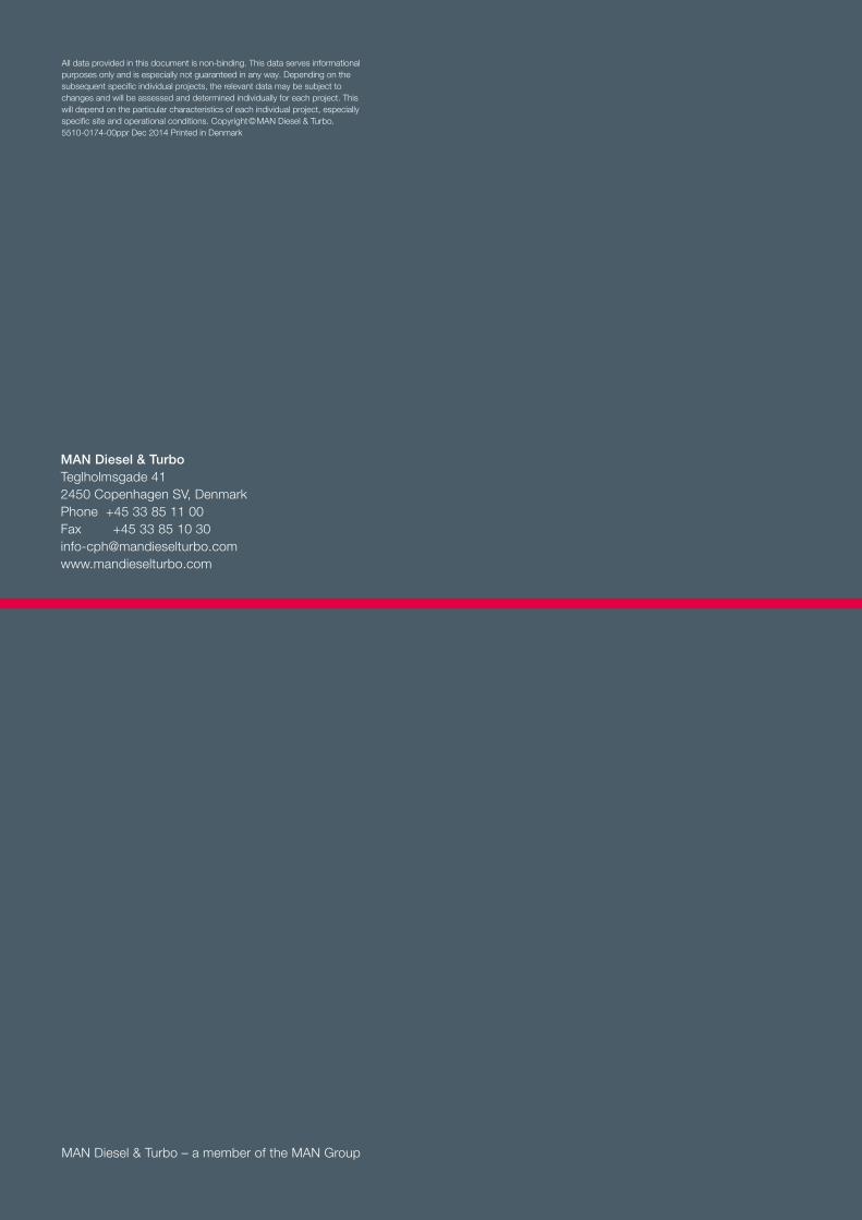
9. Compatibility between fuels
Compatibility issues arise when the
components in the fuels do not mix
well together, for example, when mix-
ing fuels with a high aromatic hydrocar-
bon content (asphaltenes), such as in
HFO, with fuels of the more aliphatic/
paraffinic type, for example distillates or
the new types of 0.1% S fuels (ULSFO).
The asphaltenes might drop out of the
suspension and the result can be vast
amounts of sludge in tanks, filters and
separators.
Some of these fuels can also have a
cleaning effect on the tanks. Sludge
from residual fuels build up over time in
the tanks, and some of the new fuels will
be able remove and carry the sludge.
The sludge may then be trapped in the
filters further down in the fuel treatment

Guidelines for Operation on Fuels with less than 0.1% Sulphur 17
• Know what is bunkered
• Inform the crew of specific challenges
• Lubricity is not considered a major issue
• Keep the fuel temperature above the pour point (heated tanks might be necessary)
• Keep the right fuel in the right tank to avoid compatibility is-sues. Check compatibility!
• Clean the fuel and remove cat-fines: use the correct temperature on the centrifuges to ensure maximum removal of cat-fines (max. limit 10 ppm).
Summary 6, 7, 8 and 9: lubricity, cat-fines, pour point and compatibility
system, see Section 4 regarding drain
from the fuel pumps.
The risk of encountering incompatibility
issues can be reduced by checking the
compatibility between the fuels before
bunkering. This can be done manually
with a kit on board (Fig. 14), or via an
independent laboratory. The latter often
being a slow process, since the ship
will have left the port before the labora-
tory returns with the test result.
Consequently, we recommend that dif-
ferent kinds of fuels are not mixed, and
that dedicated tanks are used for dif-
ferent types of fuel. Of course, the dif-
ferent fuels will mix in the fuel system
when switching fuels, e.g. from high
sulphur HFO to fuels with less than
0.1% S, and we recommend that care
must be taken during this operation.
10. Fuel change-over procedures
This section only describes the
change-over between HFO and distil-
lates or ULSFO. Change-over to LNG,
methanol, ethane or LPG takes place in
a separate fuel system and, therefore,
does not face the same challenges.
High-sulphur HFO is used at high tem-
peratures to reduce the viscosity to the
required level before the engine inlet.
Distillates are often used at rather low
temperatures to keep the viscosity suf-
ficiently high before the engine inlet.
A change-over between the fuels will
mean a change-over from high temper-
ature to low temperature, or from low
to high. The new ULSFO will often be
used at medium temperatures, thereby
reducing the challenge of the large tem-
perature difference.

Guidelines for Operation on Fuels with less than 0.1% Sulphur18
10-15
2
5Decrease cooling
Stop cooling
Start steam tracing
Start heater
Heavy Fuel (HFO)
Viscosity: 2-20 cStFuel temperature gradient: Max. 2°C/min.Load: 25-40% MCR
Diesel (DO)
Running hours
Fuel viscosity, cSt
10-15
2
10
18
Stoppreheater
� �
Start cooler
Heavy Fuel (HFO)
Viscosity: 2-20 cStFuel temperature gradient: Max. 2°C/min.
Diesel (DO)
Running hours
Fuel viscosity, cSt
Set viscosityto 18 cSt
Reduce load to 25-40%Stop steam tracing
The injection equipment needs to be
protected against rapid temperature
changes, as the large temperature
changes might otherwise cause stick-
ing or scuffing of the fuel valves, fuel
pump plungers or suction valves. The
change-over must be carried out at a
low load (25-40% MCR) and in a con-
trolled manner, and the fuel tempera-
ture gradient must not exceed 2°C/min,
see also Figs. 15 and 16.
Special care must be taken when going
from a low-viscosity fuel, which is cold,
to a high-viscosity fuel, which needs to
be heated. When the warm fuel runs to
the cold components, they will warm
up, and the material will expand slightly.
For example, the fuel plunger will warm
up first, whereas the barrel contains
more material and, therefore, its expan-
sion will take longer time, which means
that the clearance will decrease and
thereby increase the risk of seizures.
Changing the other way around, from
warm to cold fuel, is less sensitive, as
the plunger will cool down first, reduce
in size and, thereby, increase the clear-
ance and lower the risk of seizures.
It is advisable to practise the change-
over in deep waters before enter-
ing high-risk areas such as ports and
other congested areas. The complete
change-over procedure can be found
in the operation manuals.
SafeChange Controller with Diesel-
switch may be installed and used for
automatic fuel change-over. This will
enable change-over at loads up to 75%.
Contact MAN PrimeServ for more infor-
mation on installation of SafeChange
Controller with Diesel-switch (e-mail:
As mentioned above, the new ULSFO
types will often be used at medium
temperatures to reduce the challenge
of the large temperature difference.
However, similar care must be taken
when changing over to and from these
types of fuel and the maximum tem-
perature gradient during change-over
must be kept at 2°C/min.
Fig. 16: Change-over procedure from warm, high viscosity fuel e.g. HFO to cold, low viscosity fuel (e.g. diesel)
Fig. 15: Change-over procedure from cold, low viscosity fuel (e.g. diesel) to warm, high viscosity fuel (e.g. HFO)

Guidelines for Operation on Fuels with less than 0.1% Sulphur 19
11. Low-sulphur biofuel
MAN B&W two-stroke engines can run
on fuels which are within the ISO 8217
limits. However, they are also capable
of running on crude biofuel, tallow,
rapeseed oil and other kinds of biofu-
els (refer to Stationary MAN B&W MC-S
Engines for Biofuel Applications, 5510-
0098-00ppr Sep 2010). Blends of or-
dinary petroleum-based fuels and bio-
fuels, such as fatty acid methyl esters
(FAME) should not impose any larger
issues if the blends are stable and do
not produce large amounts of sludge.
However, there are factors to take into
consideration before bunkering and us-
ing fuel containing biofuel in order to
ensure a safe and reliable operation.
The cylinder oil used should be
matched with the sulphur content in
the fuel. A cylinder oil with 15-40 BN
should be utilised when operating on
0.1%S biofuel. The cylinder condition
should, as always, be monitored care-
fully, see Section 1 and SL2014-587.
Biofuels can contain organic acids that
may cause corrosion in the fuel system.
It is therefore important to measure the
acid number (AN, ASTM D664). Distil-
late fuels usually have acid numbers
below 0.5 mg KOH/g, and heavy fuel
oil (HFO) usually has less than 2.5 mg
KOH/g. For special applications, and
if the intention is to utilise fuels with a
very high AN, the materials in the fuel
injection system must be changed to
anti-corrosive materials. In such a case,
the AN has to be below 25 mg KOH/g.
Ash content and potential abrasive
components such as silicates are fac-
tors to take into account before using
biofuel. A high ash content could pre-
sent severe operational issues in sys-
tems after the engine. Abrasive materi-
als entering the engine will increase the
wear of liners and pistons.
Before using low-sulphur biofuel on
Holeby GenSets, please consult MAN
Diesel & Turbo.
Biodiesel
There are various biofuels on the mar-
ket today. One of the more common is
biodiesel. Biodiesel is for example used
either as pure biodiesel or is mixed with
diesel intended as fuel for the automo-
tive market. Biodiesel is defined as fatty
acid methyl esters (FAME) produced
from renewable sources of vegetable
oils such as rapeseed oil, soybean
oil, used frying oil and animal fats that
meets international specifications for a
B100 such as ASTM D6751and EN-
14214. The flash point limit for B100
is 130ºC, and thereby acceptable for
marine use. Occasionally, marine die-
sel oil (MDO) and marine gas oil (MGO)
can contain FAME because diesel in-
tended for the automotive market has
been blended in the marine products.
Fuel blended with biodiesel can most
certainly burn when reaching the en-
gine. However, issues may arise in the
fuel system due to acidic compounds
in the fuel. Pumps, filters and separa-
tors could also be affected. Compatibil-
ity and microbial growth during storage
might also be issues, which is also true
for other types of biofuel. For more in-
formation on handling marine fuels with
FAME, please refer to CIMAC Guideline
handling marine fuels with FAME V1.0,
2013. The current ISO 8217-2012
states that the fuel shall be free from
bio-derived materials other than “de-
minimis” levels of FAME and that blend-
ing of FAME should not be allowed.
• Know what is bunkered
• Have adequate training and procedures
• Change-over procedure can be found in the operation manual
• The change-over must be carried out at a low load (25-40% MCR)
• Fuel temperature gradient
must not exceed 2°C/min
• Be cautious when switching fuel: follow the procedures and monitor temperature and viscosity
• MAN B&W engines can run on biofuel, but there are factors to consider before use
• High acid numbers (AN), ash content, abrasive materials
• Storage considerations: com-patibility and microbial growth
• Change to a low-BN cylinder oil (15-40 BN)
• Inform the crew about poten-tial challenges
• Monitor the cylinder condition
• ISO 8217-2012: the fuel shall be free from bio-derived materials
Summary 10: fuel change-over
Summary 11 and 12: low-sulphur bio-fuel and biodiesel

Guidelines for Operation on Fuels with less than 0.1% Sulphur20
• Know what is bunkered
• Inform the crew regarding specific challenges
• Have adequate training and procedures
• Use appropriate cylinder oils and evaluate the feed rate
• Use low-BN oil for low-sulphur fuel
• Use high-BN oil for high- sulphur fuel
• Fuel pumps should be in adequate condition, if not, starting problems could occur, especially on MC engines
• Adequate fuel system: check if the necessary cooling equip-ment is working/installed
• The right fuel in the right tank to avoid compatibility issues. Check compatibility!
• Clean the fuel and remove cat-fines
• Use the correct temperature on the centrifuges in order to ensure maximum removal of cat-fines
• Be cautious when switching fuel: follow the procedures and monitor temperature and viscosity
12. Summary
Below is given a short summary of the
recommendations in this guide:
For any questions or inquiries regard-
ing the recommendations in this pa-
per, please contact our Operation
Department at the e-mail address:
Appendix
The various oil suppliers offer cylinder oils with a broad range of BN levels. Our
MAN B&W engine design is based on the 70 BN oil traditionally used, however,
as new oil products have been introduced, BN levels have changed.
When switching to a different BN level, we scale the ACC factor to the new BN
level by multiplying the ACC factor with the ratio between the new oil BN and the
previous known oil BN.
Cylinder lube feed rate = ACC × %Sfuel = FRF × %Sfuel
For example if a 25 BN oil is used for a 0.75 % S fuel, in an engine normally operat-
ing at an ACC or a feed rate factor of 0.34 g/kWh*%S for a 70 BN oil:
ACC70 = FRF70 = 0.34 g ________
(kWh×%S)
ACC25 = 70 ___ 25 × ACC70 = 70 ___ 25 × 0.34 g ________
(kWh×%S) = 0.95
g ________
(kWh×%S)
Feed rate = ACC × %S = ACC25 × %S =0.95 g ________
(kWh×%S) × 0.75%S = 0.71
g ____
kWh
When changing to a new oil brand or type, the ACC factor may need to be reas-
sessed as described above, starting with an ACC factor in the upper range. After
this, a gradual reduction can be carried out based on actual observed conditions
or the sweep test.

Guidelines for Operation on Fuels with less than 0.1% Sulphur 21

Guidelines for Operation on Fuels with less than 0.1% Sulphur22

Guidelines for Operation on Fuels with less than 0.1% Sulphur 23
MAN Diesel & TurboTeglholmsgade 412450 Copenhagen SV, DenmarkPhone +45 33 85 11 00Fax +45 33 85 10 [email protected]
MAN Diesel & Turbo – a member of the MAN Group
All data provided in this document is non-binding. This data serves informational purposes only and is especially not guaranteed in any way. Depending on the subsequent specific individual projects, the relevant data may be subject to changes and will be assessed and determined individually for each project. This will depend on the particular characteristics of each individual project, especially specific site and operational conditions. Copyright © MAN Diesel & Turbo. 5510-0174-00ppr Dec 2014 Printed in Denmark