vanadium and sulphur in marine fuels - ibia.net · pdf filevanadium and sulphur in marine...
TRANSCRIPT

Generously sponsored by
VANADIUM AND SULPHUR INMARINE FUELS

IBIA This report is copyright of The International Bunker Industry Association Ltd and 1 may not be reproduced in any form without the publisher’s written permission
IBIA is thankful to Chris Leigh-Jones, and the Technical Working Group,
for producing this interesting report
IBIA THANKS
LLOYD’S REGISTER FOR
GENEROUSLY SPONSORING THIS PUBLICATION

IBIA This report is copyright of The International Bunker Industry Association Ltd and 2 may not be reproduced in any form without the publisher’s written permission
Section One
The Effect of Vanadium in Marine Fuels
Introduction Typical Vanadium Levels What is wrong with Vanadium The Quick Explanation A More Detailed Explanation 3:1 or 1:3 Vanadium to Sodium where did it come from? What might it do to the Engine? Fuel Additives So what does all this mean?
Section Two
Low Sulphur Fuels in Marine Diesel Engines Introduction Typical Sulphur Levels What is good & bad about Sulphur Engine Operation & Theories Lubricants Theories on Engine Wear Reported when using Low Sulphur Fuels

IBIA This report is copyright of The International Bunker Industry Association Ltd and 3 may not be reproduced in any form without the publisher’s written permission
SECTION ONE
The Effect of Vanadium in Marine Fuels
1. Introduction
Vanadium is a naturally occurring element in marine fuel oil and also one, that when combined with Sodium, can cause engine damage. The following notes have been written by IBIA to offer an initial point of reference with regard to vanadium levels. Information has been gathered from publications and verbal reports and represents a synopsis of the information available.
2. Typical Vanadium Levels
The ash value of a residual fuel oil is related to the inorganic material within it, and is the result of various factors:-
The ashes in the crude oil
The source of the various streams in a refinery for the components of the fuel oil blend
Possible subsequent contamination due to sand, dirt and rust scale.
The main ash forming elements present in crude oil are:-
Aluminium Iron Nickel Calcium Silicon Sodium Vanadium
Before injection into the diesel engine the fuel is treated onboard which results in a reduction in the ash level when compared to that delivered over the ships rail.
Vanadium is contained in the oil in a soluble form, and as such the levels are unaffected during passage through a centrifuge. The main component of the ash forming elements contained in the fuel delivered to the engine is usually vanadium, with sodium being the second highest contributor. Vanadium, in an ash form, will start to reduce at test temperatures above 525 0 C, and as such the test is temperature sensitive.

IBIA This report is copyright of The International Bunker Industry Association Ltd and 4 may not be reproduced in any form without the publisher’s written permission
Maximum vanadium levers defined in the marine world are specified in ISO 8217 as:
Max Vanadium mg/kg
Fuel Grade Comments
None specified (or present)
DMX, DMA, DMB Distillate
100 DMC Distillate, some residual 150 RMA, RMB Residual 200 RME Residual 300 RMC, RMG Residual 350 RMD Residual 500 RMF Residual, high Vanadium 600 RMH, RMK, RML Residual, high Vanadium
Figure 1
Ash Content in Marine Fuel Oil
Figure 1 is a typical distribution of the ash levels in residual fuel, on a worldwide basis, and covers the complete range of viscosities (IF30 – IF420). The form of the distribution of the ash level, in the fuel delivered to the engine, would follow a similar pattern, but would be slightly displaced to the left so as to account for the removal of various elements by the onboard treatment process. These being any catalytic fines, sand and rust scale, which may be present; also sodium, if present in the fuel as seawater.
Figure 2
Water Content in Marine Fuels

IBIA This report is copyright of The International Bunker Industry Association Ltd and 5 may not be reproduced in any form without the publisher’s written permission
Figure 2 shows the distribution of water content, measured in fuel samples, from many sources, over an extended period. As a general rule, 1% water is associated with 100 mg/kg sodium. Unlike vanadium, sodium associated with water contamination, can usually be effectively removed by a well operated centrifuge system.
Vanadium is a metal element that is present in an oil soluble form in all crude oils. The levels found in residual fuels depend mainly on the crude oil source, whilst the actual level is also related to the concentrating effect of the refinery processes used in the production of the residual fuel.
Figure 3 shows a distribution of vanadium levels of residual fuel on a worldwide basis, expressed in mg/kg m/m (previously referred to as parts per million PPM). From this it can be seen that the proportion of high vanadium fuel is small and it has been estimated that this is less than 15% for vanadium levels greater than 200 mg/kg. The main bunkering areas for such fuel are the East Coast of the USA, and the Caribbean.
From time to time high vanadium fuel is found in other areas and this is attributable to the use of variable crude sources by different refineries. The crude stocks with the highest levels of vanadium are those from Venezuela and Mexico. The level of sodium usually found in residual fuels is less than 50 mg/kg, and it has been estimated that some 95% are less than 100mg/kg. (See Figure 2 where sodium is often associated with sea water contamination.)
The form in which the sodium is present determines the extent of the possible reduction in the ship’s fuel treatment plant. Sodium contamination, in the absence of water, is probably the most difficult form of this contamination to remove.

IBIA This report is copyright of The International Bunker Industry Association Ltd and 6 may not be reproduced in any form without the publisher’s written permission
3. What is wrong with Vanadium?
3.1 The Quick Explanation
High temperature corrosion and fouling are phenomena that can be mainly attributed to the vanadium and sodium content of the oil. Both these elements oxidise during combustion and, in a series of complex chemical reactions, form semi-liquid and sticky low melting point salts that adhere to exhaust valves and turbochargers. These salts are corrosive and attack the metal to which they adhere.
It is in combination that vanadium pentoxide and sodium sulphate can be harmful to the operation of the diesel engine. They are responsible for fouling, and high temperature corrosion of exhaust components.
3.2 A More Detailed Explanation
During combustion the vanadium in the fuel undergoes various changes, mainly the result of oxidation to form Vanadium Oxide (VO) and Vanadium Dioxide (VO2). Upon entering cooler areas of the combustion chamber, or exhaust duct, these gasses cool, condense and undergo further oxidation resulting in particles containing a high proportion of Vanadium Pentoxide (V2O5) on the outer layers. As V2O5 has a relatively low melting point; the condensed particles become semi-liquid and sticky, with the result that they adhere to the surface they come into contact with.
The sodium in the fuel reacts with the water vapour formed during combustion to generate sodium hydroxide. This in turn combines with the sulphur dioxide present in the exhaust gas forming Sodium Sulphate (Na2SO4). This condenses below about 890oC and will adhere to surfaces already coated with V2O5. The resultant deposits block gas passages and corrode metal surfaces.
4. 3:1 or 1:3 Vanadium to Sodium where did it come from? The melting points of some vanadium and sodium complexes are shown in Table 2. This table also shows that some of these complexes have relatively low melting points.
Table 2 Melting Point 0 C
IBIA This report is copyright of The International Bunker Industry Association Ltd and 7 may not be reproduced in any form without the publisher’s written permission
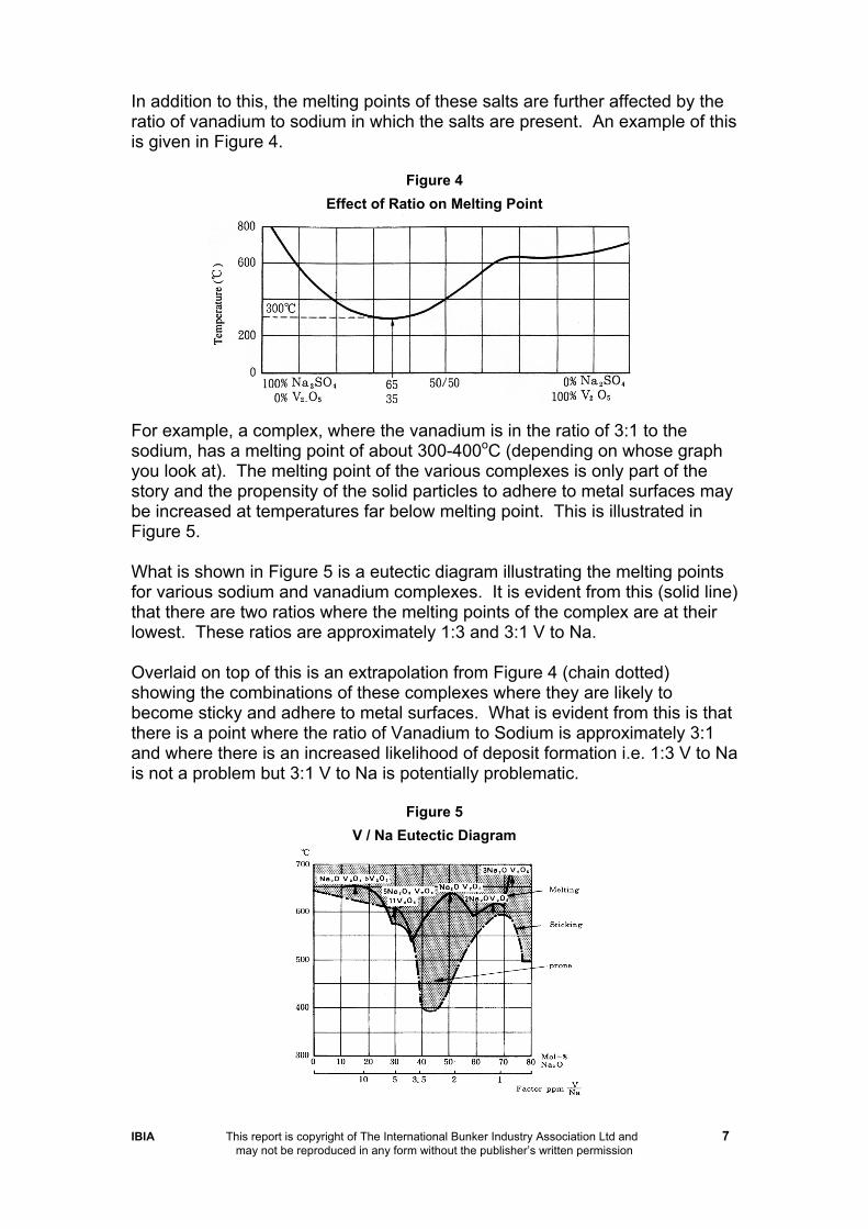
In addition to this, the melting points of these salts are further affected by the ratio of vanadium to sodium in which the salts are present. An example of this is given in Figure 4.
Figure 4
Effect of Ratio on Melting Point
For example, a complex, where the vanadium is in the ratio of 3:1 to the sodium, has a melting point of about 300-400oC (depending on whose graph you look at). The melting point of the various complexes is only part of the story and the propensity of the solid particles to adhere to metal surfaces may be increased at temperatures far below melting point. This is illustrated in Figure 5. What is shown in Figure 5 is a eutectic diagram illustrating the melting points for various sodium and vanadium complexes. It is evident from this (solid line) that there are two ratios where the melting points of the complex are at their lowest. These ratios are approximately 1:3 and 3:1 V to Na. Overlaid on top of this is an extrapolation from Figure 4 (chain dotted) showing the combinations of these complexes where they are likely to become sticky and adhere to metal surfaces. What is evident from this is that there is a point where the ratio of Vanadium to Sodium is approximately 3:1 and where there is an increased likelihood of deposit formation i.e. 1:3 V to Na is not a problem but 3:1 V to Na is potentially problematic.
Figure 5
V / Na Eutectic Diagram

IBIA This report is copyright of The International Bunker Industry Association Ltd and 8 may not be reproduced in any form without the publisher’s written permission
5. What might it do to the Engine? Figure 6 shows a large hole in the seat of an exhaust valve. This is the result of a phenomenon which involves three distinct phases.
1. Erosion: the wearing away of the metal by hot exhaust gases possibly initiated by the impacting of ash and carbon on the valve.
2. Fused salt corrosion: sodium and vanadium at high temperature form
corrosive fluxes, attacking and corroding exhaust valves, turbocharger nozzles and blades. The salts dissolve protective oxide layers facilitating the further gas phase oxidation.
3. Gas phase oxidation: the effect of oxygen in the hot exhaust on metal
engine surfaces.
Figure 6
The extent of hot corrosion and fouling is generally kept at an acceptable level by the design and operation of diesel engines. The principal means by which corrosion is minimised is by control of temperature. It is essential to ensure that exhaust valve temperatures are maintained at temperatures below the levels at which liquid sodium and vanadium complexes are formed. This is the reason why the temperature of exhaust valve seats and faces is usually limited to below 4500C. In recent years, engine designers have incorporated materials into exhaust valve and seats which are resistant to the corrosive components of the fuel oil ash. Some engine builders use a Stellite facing whilst others use nimonic steels in valve manufacture. Also, an increasing number of designs include exhaust valve rotators which are said to extend the life. This is achieved of the valve by smoothing the radial temperature distribution around the valve and preventing repeated impact damage at a single point on the valve face.
Some older designs of diesel engines do not have the benefit of modern materials and have high operating temperatures. As a result of this they are prone to hot corrosion problems and in general the fuel specifications for such engines have a low limiting value for vanadium. As discussed above it is the combination of vanadium and sodium that may lead to problems in the post combustion phase.

IBIA This report is copyright of The International Bunker Industry Association Ltd and 9 may not be reproduced in any form without the publisher’s written permission
It is for this reason that the ISO 8217 (1987) standard provides fuel grades with lower vanadium (and MCR) limits than the original BS MA 100 (1982) levels (e.g. 600 became 300 or 600, 500 became 500 or 200 mg/kg). This was partly the result of a revised CIMAC recommendation issued during the interim period between the creation of the two standards. The lower limits reflected the view of the diesel engine industry (CIMAC) that some older engine designs were susceptible to hot corrosion. These engines would typically be those originally designed for operation on distillate fuels. 6. Fuel Additives In order to reduce these corrosion problems an additive which has the effect of an ash modifier may, under certain circumstances, be beneficial. The actual type of ash formed, and its properties depend upon the operating conditions, and are also influenced by the sulphur gases present and carbon. Hence, the ash modifier should have the ability to increase the melting point temperature and makes the ash more friable. By increasing the melting point temperature, the temperature may reach a point when the ash is not in a molten form and will not be corrosive. In being more friable the ash is likely to stick to metal surfaces and affect heat transfer. There are numerous ash-modifying chemicals that include compounds based on aluminium, barium, calcium, magnesium and silicon. These different compounds affect the melting process in different ways, and the physical nature of the conditioned ash also varies, depending on which compound is used. Aluminium tends to produce light but voluminous compounds, whilst those based on barium and calcium tend to form hard insoluble deposits. Magnesium based ash modifiers give rise to very voluminous deposits. Situations can arise when the effect of the ash modifier, by incorrect application, can cause further problems in the downstream post combustion process. 7. So what does this all mean? Vanadium is a significant ash forming constituent of fuel oil and reportedly the one that arouses most interest from ship owners. For a fixed level of contamination, there is an increased potential to deposit formation if the ratio of vanadium to sodium contamination is in the ratio of 3:1. However, the total level of contamination is as important as the ratio of contamination, and modern fuel standards are designed to reflect this. Although ISO 8217 has a maximum limit of 600mg/kg vanadium, it is unusual in practise for a value of 400 mg/kg to be exceeded. The incidence of high vanadium levels (>400 mg/kg) entering the marine bunker market is small (<5%). The incidence of high sodium levels, typically associated with seawater contamination is small (< 1% of deliveries > 100 mg/kg). Correct operation of

IBIA This report is copyright of The International Bunker Industry Association Ltd and 10 may not be reproduced in any form without the publisher’s written permission
the ships fuel settling and centrifuge systems will remove the great majority of water contamination (>90% removal efficiency). Care should be taken to correctly centrifuge fuel where there is a risk of high water and vanadium levels. Modern generation engines designed from the outset for operation on residual fuels will not be susceptible to high temperature corrosion provided they are well maintained and operated within their design envelope. Such engines will typically have sophisticated alloy valve seats and valve rotators. High vanadium and sodium fuels will increase the tendency for deposit formation in the exhaust passages. Ash deposits can cause fouling in addition to corrosion problems. Fouling in the exhaust ducts and turbocharger passages can be controlled by means of regular water washing. Pre and post combustion additives can assist in maintaining cleanliness in the exhaust passages. In the present generation of diesel engines high levels of vanadium in the fuel should not present any operational problems if regular water washing of the turbocharger is carried out.
This technical update is provided in good faith by IBIA for the information of IBIA members only
and no responsibility can be taken by IBIA for the information and recommendations contained herein.
C Leigh-Jones, Technical Working Group of the IBIA 28 Feb 1998

IBIA This report is copyright of The International Bunker Industry Association Ltd and 11 may not be reproduced in any form without the publisher’s written permission
SECTION TWO
Low Sulphur Fuels in Marine Diesel Engines
Introduction From time to time comments are circulated around the bunker and marine industry about problems associated with engine operation on fuels with a low sulphur content. The notes below have been written by IBIA to offer an initial point of reference with regard to this perceived problem. Information has been gathered from publications and verbal reports and represents synopses of the total information available. 1. Typical Sulphur Levels Sulphur is found in crude oil as a naturally occurring element. The level of sulphur in the crude is generally indicative of the levels of sulphur that will occur in the residual fuel stream obtained from that crude. This may be later altered by the effects of blending and dilution with feed stock derived from differing crude oils and refinery processes. Sulphur levels, as defined in the marine world, are specified in ISO 8217 as: Max Sulphur Level
Fuel Grade Comments
1% DMX Emergency Gen Set Fuel 1.5% DMA Distillate 2% DMB, DMC Distillate 3.5% RMA, RMB, RMC Residual 4% RMD Residual 5% RME all grades to RML Residual It should be noted that these levels represent maximum limits and in its present form ISO 8217 does not attempt to specify a minimum level for sulphur content. The sulphur level in marine distillate fuels (defined by DMA and DMB) varies on a worldwide basis. In the case of DMA, which may be described as gas

IBIA This report is copyright of The International Bunker Industry Association Ltd and 12 may not be reproduced in any form without the publisher’s written permission
oil, this is manufactured primarily for the inland market, and may have a very low sulphur content to meet local regulations. For example 0.05% sulphur is commonly used in automotive engines. It is known that at very low sulphur levels a distillate fuel has reduced lubricity properties and this is overcome by the use of suitable additives. Figure 1 shows the distribution of sulphur in residual fuel on a worldwide basis, the great majority of samples being in the band 1% - 3.5%. Low sulphur marine fuels form only a small percentage of the total. Such fuels are typically available form China, Argentina and Brazil. This low sulphur residual fuel occurs because the crude oil used in its manufacture is known as “sweet crude”, namely one which contains a low level of sulphur.
Figure 1
Sulphur Content in Marine Fuel Deliveries
Residual fuels used in land based applications can have much lower sulphur content than the maximum levels specified in ISO 8217. This is due to the overriding influence of air pollution control legislation. Normally such fuel commands a higher price than marine fuel oil, which by ISO 8217 may contain up to 5% wt sulphur fuel designated for the land market to enter the marine bunker network. 2. What is Good and Bad about Sulphur? Sulphur will burn and release useful energy so this extent it is a least more useful than water contamination. However the amount of energy released is less than would be obtained from typical fuel hydrocarbons in so far as each percentage of fuel sulphur represents an energy loss of about 0.3 MJ/kg. Figure 2 shows the relationship between energy content and sulphur levels for a range of differing fuel densities. Sulphur will attack the surface of fuel injection components forming very thin layers of metallic sulfides. This appears to be a distinct disadvantage but is in reality exactly the opposite. These layers will easily shear and help to prevent micro-welding and scuffing of the machined surfaces as they rub against each other during normal engine operation. In effect what is happening is the sulphur in a fuel acts as a natural EP (Extreme Pressure) additive in much the same way as those artificially added to high performance lubricants. Fuel injection components are subject to quite extreme forces during operation and their designs often rely on some natural lubricity in the fuel passing through the pumps. Take this away and damage often ensues.
IBIA This report is copyright of The International Bunker Industry Association Ltd and 13 may not be reproduced in any form without the publisher’s written permission
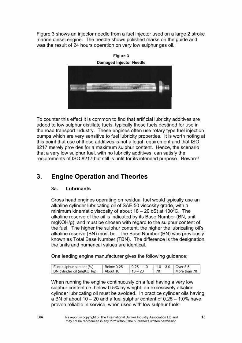
Figure 3 shows an injector needle from a fuel injector used on a large 2 stroke marine diesel engine. The needle shows polished marks on the guide and was the result of 24 hours operation on very low sulphur gas oil.
Figure 3
Damaged Injector Needle
To counter this effect it is common to find that artificial lubricity additives are added to low sulphur distillate fuels, typically those fuels destined for use in the road transport industry. These engines often use rotary type fuel injection pumps which are very sensitive to fuel lubricity properties. It is worth noting at this point that use of these additives is not a legal requirement and that ISO 8217 merely provides for a maximum sulphur content. Hence, the scenario that a very low sulphur fuel, with no lubricity additives, can satisfy the requirements of ISO 8217 but still is unfit for its intended purpose. Beware! 3. Engine Operation and Theories
3a. Lubricants
Cross head engines operating on residual fuel would typically use an alkaline cylinder lubricating oil of SAE 50 viscosity grade, with a minimum kinematic viscosity of about 18 – 20 cSt at 1000C. The alkaline reserve of the oil is indicated by its Base Number (BN, unit mgKOH/g), and must be chosen with regard to the sulphur content of the fuel. The higher the sulphur content, the higher the lubricating oil’s alkaline reserve (BN) must be. The Base Number (BN) was previously known as Total Base Number (TBN). The difference is the designation; the units and numerical values are identical.
One leading engine manufacturer gives the following guidance:
Fuel sulphur content (%) Below 0.25 0.25 – 1.0 1.0 – 3.0 Over 3.5 BN cylinder oil (mgKOH/g) About 10 10 – 20 70 More than 70
When running the engine continuously on a fuel having a very low sulphur content i.e. below 0.5% by weight, an excessively alkaline cylinder lubricating oil must be avoided. In practice cylinder oils having a BN of about 10 – 20 and a fuel sulphur content of 0.25 – 1.0% have proven reliable in service, when used with low sulphur fuels.

IBIA This report is copyright of The International Bunker Industry Association Ltd and 14 may not be reproduced in any form without the publisher’s written permission
3b. Theories on Engine Wear Reported when Using Low Sulphur Fuels
From time to time problems have been experienced by crosshead marine engines using low sulphur fuel. These problems manifest themselves as abnormal wear, or scuffing of piston rings and liners. They have usually been restricted to one or two cylinders in the engine. There is some debate on the real significance of the phenomenon and one school of opinion states that the low sulphur problem has been inflated, or that it simply does not exist. Others suggest that if an unfortunate experience has occurred with low sulphur fuel, this was as a result of other reasons besides the low sulphur content itself.
Manufacturers of crosshead engines are divided on the seriousness of the low sulphur problem. Some believe it is undesirable to use a highly alkaline oil in conjunction with a low sulphur fuel and, as mentioned, issue recommendations linking oil alkalinity with various levels of sulphur. Historically, ship operators have manoeuvred the engines on diesel oil which typically has a sulphur level of less that 1% (dependent upon the source of the fuel). The time spent manoeuvring could be many hours if, for example, a transit was being made of the Suez Canal or St Laurence Seaway. During this period the cylinder lubricant applied to the engine was still highly alkaline. Today the majority of ocean going ships run pier to pier on residual fuel, thus potential problems from this area is greatly reduced. Engine Manufacturers have different theories for the high wear that can sometimes occur when low sulphur fuels are used. One opinion is that this wear is basically associated with poor “running in”. According to this theory a certain degree of continuous controlled wear between the piston rings and cylinder is necessary to maintain a good seal between the rubbing surfaces by preventing the surfaces from becoming polished. Polished metal surfaces lose their ability to retain a reservoir of oil within the surface topography. With little or no oil retention there is an increased likelihood of micro-seizure leading to scuffing and high wear rates. Figure 4 shows a plot of the surface of a cylinder liner. The vertical ordinate is greatly magnified to illustrate the various peaks and valleys. It can be seen that the majority (>70%) of the peaks and troughs are small and this provides a good bearing area to take the thrust from the piston rings and skirt (this is known as Plateau Honing). A small number of valleys are much deeper and these act as reservoirs for the lube oil. Polishing of the liner (or piston ring) surfaces removes these valleys and leads to scuffing.

IBIA This report is copyright of The International Bunker Industry Association Ltd and 15 may not be reproduced in any form without the publisher’s written permission
Figure 4
Plot of the surface of a cylinder liner
High wear rates with low sulphur fuel have been attributed to deposits on the crown lands of the piston. This is the area between the top piston groove and the top of the piston crown. This area can contact the cylinder liner as the piston tilts during load reversal between compression and firing strokes. This can occur especially on trunk piston type engines where there is no cross head guide, and the piston skirt provides vertical alignment as shown in Figure 5.
Figure 5
Diesel Engine Piston
This theory suggests that a combination of low sulphur fuel and high alkalinity oil alters the chemical nature of the crown land

IBIA This report is copyright of The International Bunker Industry Association Ltd and 16 may not be reproduced in any form without the publisher’s written permission
deposits compared to that formed when a fuel of high sulphur is used. There is a further divergence on the manner in which such deposits affect wear. One view is that these deposits are harder when low sulphur is used and therefore a form of abrasive wear is promoted. Another theory is that the structure of the deposits with the low sulphur fuel is such that they act as a sponge for the oil, which results in lack of lubrication of the cylinder and leads to scuffing. The results of work carried out in a combustion flame photography rig have shown that the flame characteristics of low sulphur fuels from around the world have distinct variations. Whilst it was not surprising that the flame spread faster with volatile fuels compared to residual fuels, the duration of the flame between the fuels had considerable differences. Expressed in terms of crank angle degrees, this amounted to up to 300. For comparison, typical full load combustion periods are around 60 – 800 of crank angle. Late, or slow combustion, will increase the thermal load on cylinder components leading to overheating and lubrication problems. Some low sulphur fuels originating in China have been shown to demonstrate this potential. In this instance problems could be attributed to low sulphur levels, when in fact the unusual combustion characteristics of the fuel provide a more likely explanation. Other laboratory work, from a study of cylinder oil drainings, has suggested that operation on low sulphur fuels tended to increase the rate of oxidation of the cylinder oil. The practical result of such oxidation would have been an increase in the viscosity of the oil. This increase could be sufficient to hinder the distribution of the lubricant within the combustion chamber resulting in sticking of the piston ring pack. As a result of this there would be increased gas blow-by , which would lead to a breakdown of the oil film on the cylinder walls. With failure of the lubricating system there would be an increase in friction and resultant scuffing. As in practice the thermal loading on all units of a direct drive crosshead engine is not equal, damage in the form of scuffing would be first seen in those units most thermally loaded, or those with faulty combustion. Overall the instances of the low sulphur problem appear to be rare, but when they do exist, high piston and liner wear has been reported. Strict adherence to the designed operating conditions, and correct combustion performance, minimises any possible problem. The use of a low BN cylinder lubricant, whilst being technically desirable when compared to the usual high BN, may not always be possible because of the supply constraints of such a product. If a vessel is regularly trading on low sulphur fuel consideration should be given to the provision of tankage and piping for a low alkalinity cylinder lubricant.

IBIA This report is copyright of The International Bunker Industry Association Ltd and 17 may not be reproduced in any form without the publisher’s written permission
This technical update is provided in good faith by IBIA for the information of IBIA Members only
and no responsibility can be taken by IBIA for the information and recommendations contained herein.