guide for in-place treatment of wood in historic covered
TRANSCRIPT
Guide for In-Place Treatment of Wood
in Historic Covered and Modern
Bridges
Course No: S04-020
Credit: 4 PDH
Gilbert Gedeon, P.E.
Continuing Education and Development, Inc. 22 Stonewall Court
Woodcliff Lake, NJ 07677
P: (877) 322-5800
Guide for In-Place Treatment of Wood in Historic Covered and Modern Bridges Stan LebowGrant KirkerRobert WhiteTerry AmburgeyH. Michael BarnesMichael SandersJeff Morrell
United StatesDepartment ofAgriculture
Forest Service
ForestProductsLaboratory
GeneralTechnical ReportFPL–GTR–205
250 mL
200 mL
150 mL
100 mL
50 mL
In cooperation with theUnited StatesDepartment ofTransportationFederal Highway Administration
March 2012
Lebow, Stan; Kirker, Grant; White, Robert; Amburgey, Terry; Barnes, H. Michael; Sanders, Michael; Morrell, Jeff. 2012. Guide for In-Place Treat-ment of Wood in Historic Covered and Modern Bridges. General Technical Report FPL-GTR-205. Madison, WI: U.S. Department of Agriculture, For-est Service, Forest Products Laboratory. 43 p.
A limited number of free copies of this publication are available to the public from the Forest Products Laboratory, One Gifford Pinchot Drive, Madison, WI 53726–2398. This publication is also available online at www.fpl.fs.fed.us. Laboratory publications are sent to hundreds of libraries in the United States and elsewhere.
The Forest Products Laboratory is maintained in cooperation with the University of Wisconsin.
The use of trade or firm names in this publication is for reader information and does not imply endorsement by the United States Department of Agriculture (USDA) of any product or service.
The USDA prohibits discrimination in all its programs and activities on the basis of race, color, national origin, age, disability, and where applicable, sex, marital status, familial status, parental status, religion, sexual orienta-tion, genetic information, political beliefs, reprisal, or because all or a part of an individual’s income is derived from any public assistance program. (Not all prohibited bases apply to all programs.) Persons with disabilities who require alternative means for communication of program informa-tion (Braille, large print, audiotape, etc.) should contact USDA’s TARGET Center at (202) 720–2600 (voice and TDD). To file a complaint of discrimi-nation, write to USDA, Director, Office of Civil Rights, 1400 Independence Avenue, S.W., Washington, D.C. 20250–9410, or call (800) 795–3272 (voice) or (202) 720–6382 (TDD). USDA is an equal opportunity provider and employer.
AbstractHistoric covered bridges and current timber bridges can be vulnerable to damage from biodeterioration or fire. This guide describes procedures for selecting and applying in-place treatments to prevent or arrest these forms of degrada-tion. Vulnerable areas for biodeterioration in covered bridg-es include members contacting abutments, members near the ends of bridges subject to wetting from splashing and members below windows or other openings that allow entry of wind-blown precipitation. Pressure-treated timber bridge members can be vulnerable when untreated wood is exposed by field fabrication or by the development of drying checks. The objective of an in-place preservative treatment is to distribute preservative into areas of a structure that are vulnerable to moisture accumulation and/or not protected by the original pressure treatment. Types of field treatments range from finishes, to boron rods or pastes, to fumigants. A limitation of in-place treatments is that they cannot be forced deeply into the wood as is done in pressure-treatment processes. However, some can be applied into the center of large members via treatment holes. These preservatives may be available as liquids, rods or pastes. Bridge members can be treated with fire retardants to delay ignition, reduce heat release, and slow the spread of flames. In-place coating products are available to reduce surface flammability, but these coatings may need to be reapplied on a regular basis if exposed to weathering. For more integrated protection, fire retardant treatment of bridge members may be combined with other forms of protection such as lights, alarms, sprinklers and monitoring systems.
Keywords: guide, covered bridge, timber bridge, deterioration, fire, wood preservatives, in-place treatment
This study is part of the Research, Technology and Education portion of the National Historic Covered Bridge Preservation (NHCBP) Program administered by the Federal Highway Administration. The NHCBP program includes preservation, rehabilitation and resto-ration of covered bridges that are listed or are eligible for listing on the National Register of Historic Places; research for better means of restoring, and protecting these bridges; development of educational aids; and technology transfer to disseminate information on cov-ered bridges in order to preserve the Nation’s cultural heritage.
This study is conducted under a joint agreement be-tween the Federal Highway Administration–Turner Fairbank Highway Research Center, and the Forest Service – Forest Products Laboratory.
Federal Highway Administration Program Manager– Sheila Rimal Duwadi, P.E.
Forest Products Laboratory Program Manager– Michael A. Ritter, P.E.
ContentsIntroduction ............................................................................................. 1 Causes of Biodegradation ................................................................... 1 Effects of Climate ............................................................................... 2 Role of Wood Structure ....................................................................... 3 Problem Areas for Biodegradation in Wooden Bridges ...................... 3 Good Practices .................................................................................... 7Types of Supplemental Treatments ......................................................... 8 Water-Diffusible Preservatives ........................................................... 9 Non-Diffusible Liquid Treatments .................................................... 12 Fumigants .......................................................................................... 13Applying Supplemental Treatments ...................................................... 14 Internal Treatments ........................................................................... 14 Water-Diffusible Internal Treatments ................................................ 14 Fumigants .......................................................................................... 15 Non-Diffusible Liquids ..................................................................... 16 External Treatments .......................................................................... 16Research on the Use of Supplemental Preservative Treatments for Covered Bridges .................................................................................... 17Summary of Supplemental Treatment Concepts ................................... 21 Liquid Surface Treatments ................................................................ 21 Paste Surface Treatments .................................................................. 21 Internal Treatments ........................................................................... 21 Example Supplemental Treatment Applications ............................... 22Who Can Apply Supplemental Preservative Treatments? .................... 31 The EPA Pesticide Label is the Law ................................................. 31 Collection of Drill Savings ............................................................... 32Fire Prevention ...................................................................................... 32 Contributing Factors ......................................................................... 32 Research on the Use of Supplemental Fire-Retardant Treatments for Covered Bridges .......................................................................... 34 Fire Protection Technology ............................................................... 35Conclusions ........................................................................................... 35References ............................................................................................. 37Additional Sources ................................................................................ 38Appendix—Contact Information for State Offices Conducting the U.S. EPA’s Certified Pesticide Applicator (CPA) Program ................... 39

Guide for In-Place Treatment of Wood in Historic Covered and Modern BridgesStan Lebow, Research Forest Products TechnologistGrant Kirker, Research Forest Products TechnologistRobert White, Research Forest Products TechnologistForest Products Laboratory, Madison, Wisconsin
Terry Amburgey, Professor Emeritus, Department of Forest ProductsH. Michael Barnes, Professor, Department of Forest ProductsMichael Sanders, Senior Research Associate, Department of Forest ProductsMississippi State University, Starkville, Mississippi
Jeff Morrell, Wood Science and Engineering ProfessorOregon State University, Corvallis, Oregon
IntroductionWooden bridges have a long history of use throughout the world, and like bridges made of other materials, the service life of wooden bridges can be enhanced through proper construction, inspection, and maintenance. Wooden bridges, whether historic covered bridges or current highway timber bridges, can be vulnerable to damage from biodegradation. Because of the long history of using wooden bridges, the causes of wood biodeterioration are well documented, as are the means to mitigate their effects. Biodeterioration is mini-mized through design and construction practices, and in the case of modern timber bridges, through pressure treatment of the timbers with wood preservatives. However, the po-tential for degradation remains, and over time many bridges need maintenance that may include in-place treatment with preservatives. Fire is also a major threat, particularly for covered bridges. In this manual, we describe procedures for selecting and applying in-place treatments to bridges to prevent or arrest degradation. This guide focuses on preser-vative treatments to protect against biodeterioration, but also briefly discusses approaches for minimizing damage caused by fire.
Causes of BiodegradationSome understanding of the causes of biodegradation is help-ful when considering in-place treatment. Because there are many excellent sources of information on the organisms that damage wooden structures (see References), this guide pro-vides only a brief summary.
In most applications of wooden construction materials, de-cay fungi are the most destructive organisms. Fungi are mi-croscopic thread-like organisms whose growth depends on mild temperatures, moisture, and oxygen. In part, the high degree of damage by wood-decay fungi reflects their ubiquitous presence in all locations. Given suitable
conditions, attack by some type of wood-decay fungus is assured. Numerous species of fungi colonize wood, and they have a range of preferred environmental conditions. Decay fungi are often separated into three major groups: brown-rot fungi, white-rot fungi, and soft-rot fungi. Brown rot and white rot are usually the most destructive and are the fungi most likely to be found in wood above ground. These two groups of decay fungi have differences in wood species preferences and in the manner that they degrade the wood, but the optimal environmental conditions to cause wood decay are fairly similar for both groups. Both decay types can cause substantial damage in a relatively short amount of time. Soft-rot fungi, in contrast, generally prefer wetter, and sometimes warmer, environmental conditions. Damage by soft-rot fungi resembles that by brown-rot fungi, but typi-cally occurs more slowly and nearer to the wood surface.
Termites follow fungi in terms of the amount of damage to wood structures in the United States. Their damage can occur more rapidly than that caused by decay, but their geo-graphic distribution is less uniform. Numerous termite spe-cies are native to the United States, and like decay fungi, the type and severity of attack varies by species. Termite species in the United States can be grouped into the categories of ground-inhabiting (subterranean) or wood inhabiting (non-subterranean) termites. Most damage in the United States is caused by species of subterranean termites. The threat from subterranean termites has increased with the spread of the non-native Formosan subterranean termite (FST) in some areas of the southeastern United States. Non-subterranean termites are less damaging because they have a narrower geographic range and degrade wood more slowly due to smaller colony size.
Other types of insects such as powderpost beetles and car-penter ants can cause notable damage in some situations, but their overall significance pales in comparison to decay fungi
General Technical Report FPL–GTR–205
2
and termites. Other organisms, including bacteria and mold, can also cause damage in some situations. Several types of marine organisms degrade wood placed in seawater. On an economic basis, however, decay fungi and termites are by the far the most destructive pests of wood used in terrestrial applications.
Effect of ClimateWe have long recognized that exposed wood deteriorates more rapidly in warm, wet climates than in cold and/or dry climates. Historically, use of wood as a construction mate-rial mirrored this effect, with greatest use occurring in north-ern latitudes. The two greatest factors influencing regional biodeterioration hazard are temperature and moisture. The growth of most decay fungi is negligible at temperatures below 2 °C (36 °F) and relatively slow at temperatures from 2 to 10 °C (36–50 °F). The growth rate then increases rap-idly, with most fungi having optimum growth rates at tem-peratures between 24 and 35 °C (75–95 °F). Soft-rot fungi typically tolerate warmer temperatures than brown- and white-rot fungi. Fungal growth rate declines steeply at higher temperatures, with little growth above 40 °C (104 °F) and no growth above 46 °C (115 °F). In most loca-tions and applications in the United States, the lower end of this temperature range has the greatest effect on fungal growth. Northern regions of the United States may have sev-eral months of the year when temperatures are continuously too low for growth of decay fungi and other months when conditions for growth are only intermittently favorable. The result, as we see from practical experience, is that decay progresses more rapidly in warmer regions of the United States. Although temperatures on the surface of wood ex-posed to sunlight can exceed those favored by decay fungi, the inner portions of wood products are usually cooler. Decay tends to develop more rapidly in wood in shaded locations, but this is usually associated with a slower rate of drying rather than with protection from excessive heat.
The role of moisture in biodeterioration, especially by decay fungi, cannot be overemphasized. Decay fungi require a moisture content of at least 20% to sustain any growth, and higher moisture contents (over 29%) are required for initial spore germination. Decay fungi cannot colonize wood with a moisture content (MC) below the fiber saturation (average of 30% MC). Free water must be present. Most brown- and white-rot decay fungi prefer wood in the moisture content range of 40% to 80%. Growth at lower moisture contents is much slower, and typically wood with a moisture content of less than 25% cannot be attacked unless the fungus has another source of moisture nearby. Previously established fungi are not necessarily eliminated at even lower moisture contents. Some species of decay fungi produce thick-walled resting spores and have been reported to survive (without further growth) for years on wood at moisture contents around 12%. As the moisture content exceeds 80%, void spaces in the wood are increasingly filled with water. The subsequent lack of oxygen and build-up of carbon dioxide
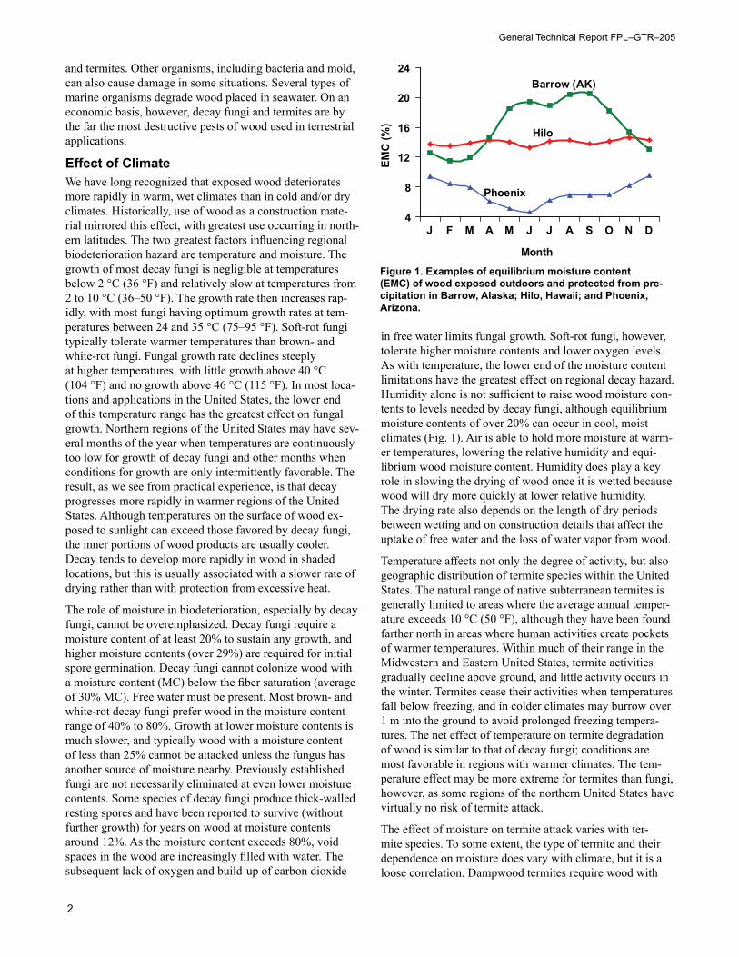
in free water limits fungal growth. Soft-rot fungi, however, tolerate higher moisture contents and lower oxygen levels. As with temperature, the lower end of the moisture content limitations have the greatest effect on regional decay hazard. Humidity alone is not sufficient to raise wood moisture con-tents to levels needed by decay fungi, although equilibrium moisture contents of over 20% can occur in cool, moist climates (Fig. 1). Air is able to hold more moisture at warm-er temperatures, lowering the relative humidity and equi-librium wood moisture content. Humidity does play a key role in slowing the drying of wood once it is wetted because wood will dry more quickly at lower relative humidity. The drying rate also depends on the length of dry periods between wetting and on construction details that affect the uptake of free water and the loss of water vapor from wood.
Temperature affects not only the degree of activity, but also geographic distribution of termite species within the United States. The natural range of native subterranean termites is generally limited to areas where the average annual temper-ature exceeds 10 °C (50 °F), although they have been found farther north in areas where human activities create pockets of warmer temperatures. Within much of their range in the Midwestern and Eastern United States, termite activities gradually decline above ground, and little activity occurs in the winter. Termites cease their activities when temperatures fall below freezing, and in colder climates may burrow over 1 m into the ground to avoid prolonged freezing tempera-tures. The net effect of temperature on termite degradation of wood is similar to that of decay fungi; conditions are most favorable in regions with warmer climates. The tem-perature effect may be more extreme for termites than fungi, however, as some regions of the northern United States have virtually no risk of termite attack.
The effect of moisture on termite attack varies with ter-mite species. To some extent, the type of termite and their dependence on moisture does vary with climate, but it is a loose correlation. Dampwood termites require wood with
4
8
12
16
20
24
J F M A M J J A S O N D
Month
EMC
(%)
Barrow (AK)
Hilo
Phoenix
Figure 1. Examples of equilibrium moisture content (EMC) of wood exposed outdoors and protected from pre-cipitation in Barrow, Alaska; Hilo, Hawaii; and Phoenix, Arizona.
Guide for In-Place Treatment of Covered and Timber Bridges
3
high moisture levels and typically only attack wood that is in direct contact with the ground. As a result, their effect on wooden structures is relatively minor. Their high moisture requirements coincide with their preferred habitats in the northwestern United States and southern Florida, but they are found in the southwestern United States as well. Native subterranean termites require moisture to prevent desicca-tion, but can attack wood at moisture contents well below the fiber saturation point by building shelter tubes upward from their nests in the ground. Native subterranean termites are widely distributed in the southern two-thirds of the Unit-ed States, although their distribution is less uniform along the Pacific Coast. Formosan subterranean termites also require a source of moisture to attack wood above ground but are less reliant on proximity to soil for survival. They may establish colonies on upper floors of buildings if a con-sistent source of moisture is present. Drywood termites are so-named because they are able to survive in wood above ground, and can often derive sufficient moisture solely from the wood. They are commonly found in southern California, Arizona, and in coastal areas from South Carolina to Texas.
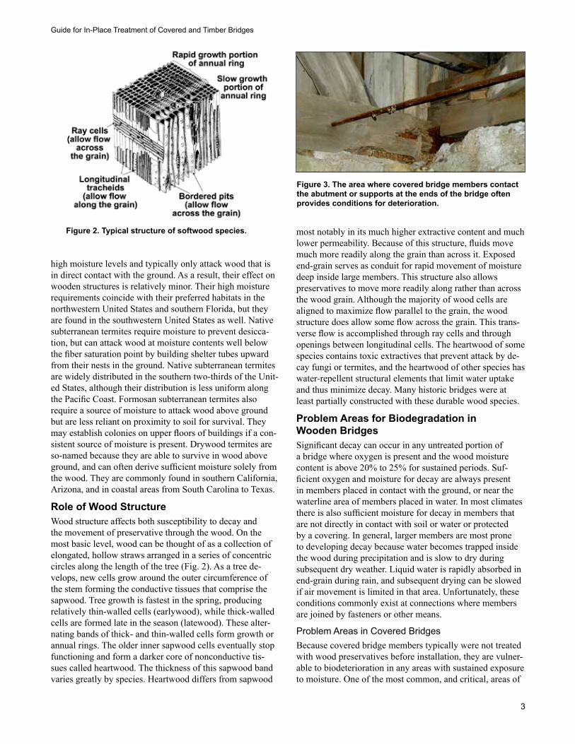
Role of Wood StructureWood structure affects both susceptibility to decay and the movement of preservative through the wood. On the most basic level, wood can be thought of as a collection of elongated, hollow straws arranged in a series of concentric circles along the length of the tree (Fig. 2). As a tree de-velops, new cells grow around the outer circumference of the stem forming the conductive tissues that comprise the sapwood. Tree growth is fastest in the spring, producing relatively thin-walled cells (earlywood), while thick-walled cells are formed late in the season (latewood). These alter-nating bands of thick- and thin-walled cells form growth or annual rings. The older inner sapwood cells eventually stop functioning and form a darker core of nonconductive tis-sues called heartwood. The thickness of this sapwood band varies greatly by species. Heartwood differs from sapwood
most notably in its much higher extractive content and much lower permeability. Because of this structure, fluids move much more readily along the grain than across it. Exposed end-grain serves as conduit for rapid movement of moisture deep inside large members. This structure also allows preservatives to move more readily along rather than across the wood grain. Although the majority of wood cells are aligned to maximize flow parallel to the grain, the wood structure does allow some flow across the grain. This trans-verse flow is accomplished through ray cells and through openings between longitudinal cells. The heartwood of some species contains toxic extractives that prevent attack by de-cay fungi or termites, and the heartwood of other species has water-repellent structural elements that limit water uptake and thus minimize decay. Many historic bridges were at least partially constructed with these durable wood species.
Problem Areas for Biodegradation in Wooden BridgesSignificant decay can occur in any untreated portion of a bridge where oxygen is present and the wood moisture content is above 20% to 25% for sustained periods. Suf-ficient oxygen and moisture for decay are always present in members placed in contact with the ground, or near the waterline area of members placed in water. In most climates there is also sufficient moisture for decay in members that are not directly in contact with soil or water or protected by a covering. In general, larger members are most prone to developing decay because water becomes trapped inside the wood during precipitation and is slow to dry during subsequent dry weather. Liquid water is rapidly absorbed in end-grain during rain, and subsequent drying can be slowed if air movement is limited in that area. Unfortunately, these conditions commonly exist at connections where members are joined by fasteners or other means.
Problem Areas in Covered BridgesBecause covered bridge members typically were not treated with wood preservatives before installation, they are vulner-able to biodeterioration in any areas with sustained exposure to moisture. One of the most common, and critical, areas of
Figure 2. Typical structure of softwood species.
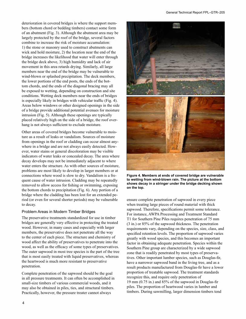
Figure 3. The area where covered bridge members contact the abutment or supports at the ends of the bridge often provides conditions for deterioration.
General Technical Report FPL–GTR–205
4
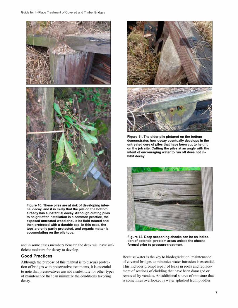
deterioration in covered bridges is where the support mem-bers (bottom chord or bedding timbers) contact some form of an abutment (Fig. 3). Although the abutment area may be largely protected by the roof of the bridge, several factors combine to increase the risk of moisture accumulation: 1) the stone or masonry used to construct abutments can wick and hold moisture, 2) the location near the end of the bridge increases the likelihood that water will enter through the bridge deck above, 3) high humidity and lack of air movement in this area retards drying. Similarly, all large members near the end of the bridge may be vulnerable to wind-blown or splashed precipitation. The deck members, the lower portions of the end posts, the ends of the bot-tom chords, and the ends of the diagonal bracing may all be exposed to wetting, depending on construction and site conditions. Wetting deck members near the ends of bridges is especially likely in bridges with vehicular traffic (Fig. 4). Areas below windows or other designed openings in the side of a bridge provide additional potential avenues for moisture intrusion (Fig. 5). Although these openings are typically placed relatively high on the side of a bridge, the roof over-hang is not always sufficient to exclude moisture.
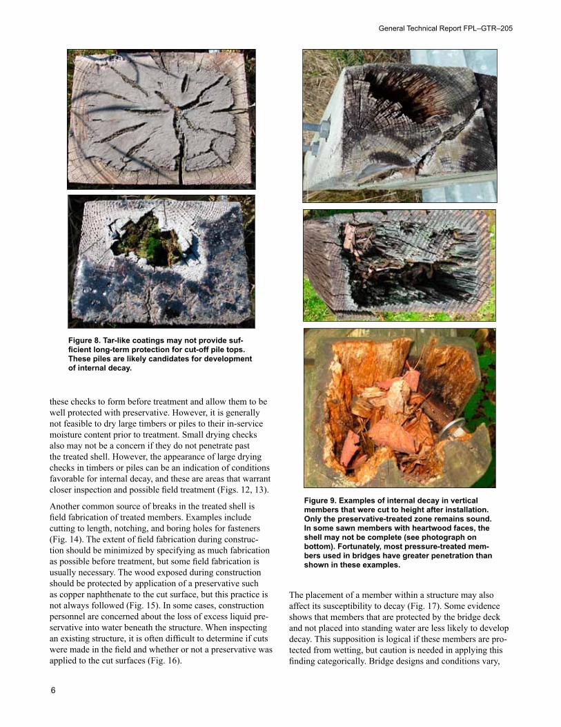
Other areas of covered bridges become vulnerable to mois-ture as a result of leaks or vandalism. Sources of moisture from openings in the roof or cladding can occur almost any-where in a bridge and are not always easily detected. How-ever, water stains or general discoloration may be visible indicators of water leaks or concealed decay. The area where decay develops may not be immediately adjacent to where water enters the structure. As with other sources of moisture, problems are most likely to develop in larger members or at connections where wood is slow to dry. Vandalism is a fre-quent cause of water intrusion. Cladding may be repeatedly removed to allow access for fishing or swimming, exposing the bottom chords to precipitation (Fig. 6). Any portion of a bridge where the cladding has been lost for an extended pe-riod (or even for several shorter periods) may be vulnerable to decay.
Problem Areas in Modern Timber BridgesThe preservative treatments standardized for use in timber bridges are generally very effective in protecting the treated wood. However, in many cases and especially with larger members, the preservative does not penetrate all the way to the center of each piece. The structure and chemistry of wood affect the ability of preservatives to penetrate into the wood, as well as the efficacy of some types of preservatives. The outer sapwood in most tree species is the part of the tree that is most easily treated with liquid preservatives, whereas the heartwood is much more resistant to preservative penetration.
Complete penetration of the sapwood should be the goal in all pressure treatments. It can often be accomplished in small-size timbers of various commercial woods, and it may also be obtained in piles, ties, and structural timbers. Practically, however, the pressure treater cannot always
ensure complete penetration of sapwood in every piece when treating large pieces of round material with thick sapwood. Therefore, specifications permit some tolerance. For instance, AWPA Processing and Treatment Standard T1 for Southern Pine Piles requires penetration of 75 mm (3 in.) or 85% of the sapwood thickness. The penetration requirements vary, depending on the species, size, class, and specified retention levels. The proportion of sapwood varies greatly with wood species, and this becomes an important factor in obtaining adequate penetration. Species within the Southern Pine group are characterized by a wide sapwood zone that is readily penetrated by most types of preserva-tives. Other important lumber species, such as Douglas-fir, have a narrower sapwood band in the living tree, and as a result products manufactured from Douglas-fir have a lower proportion of treatable sapwood. The treatment standards recognize this, and require only penetration of 19 mm (0.75 in.) and 85% of the sapwood in Douglas-fir piles. The proportion of heartwood varies in lumber and timbers. During sawmilling, larger dimension timbers tend
Figure 4. Members at ends of covered bridge are vulnerable to wetting from wind-blown rain. The picture at the bottom shows decay in a stringer under the bridge decking shown on the top.
Guide for In-Place Treatment of Covered and Timber Bridges
5
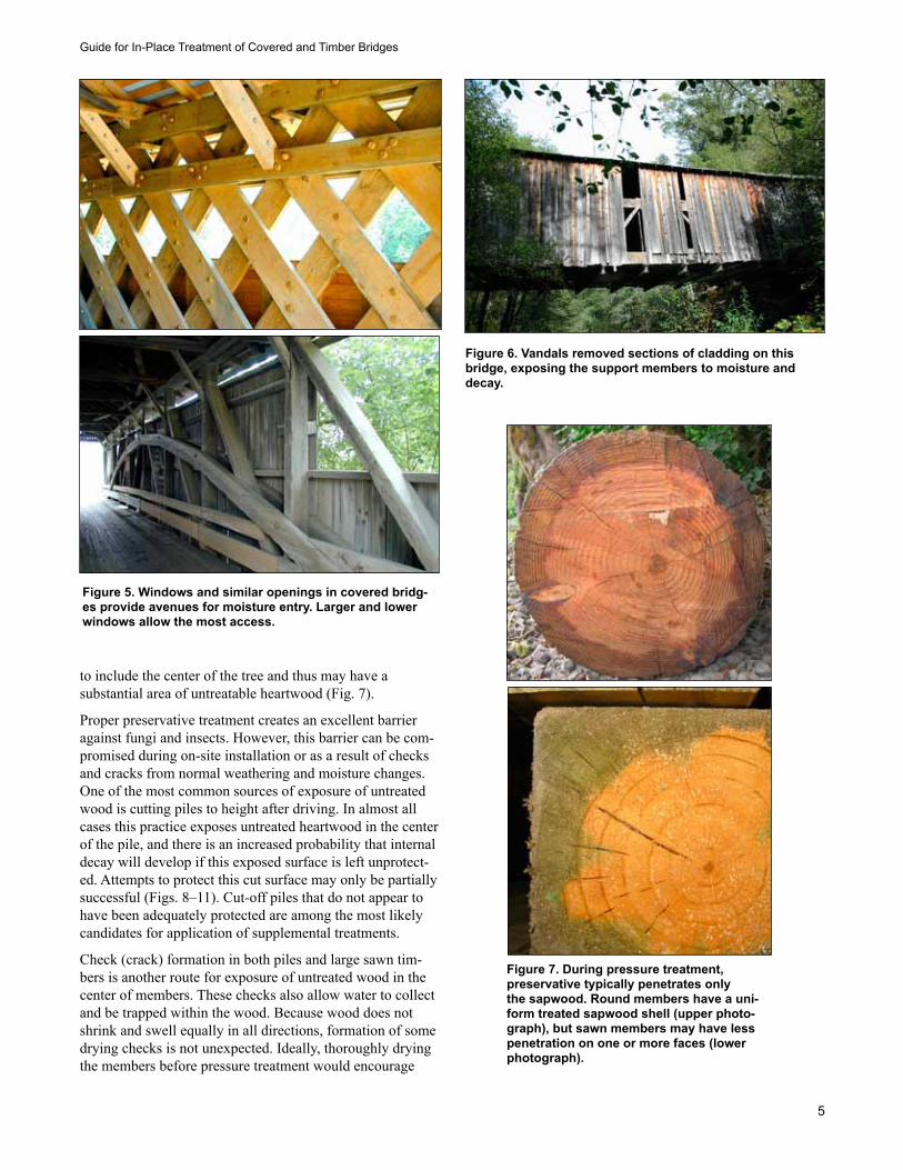
to include the center of the tree and thus may have a substantial area of untreatable heartwood (Fig. 7).
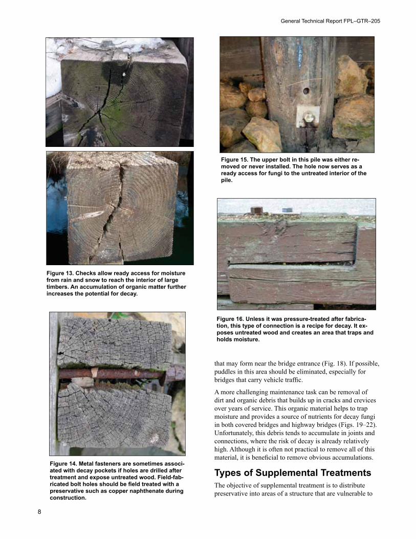
Proper preservative treatment creates an excellent barrier against fungi and insects. However, this barrier can be com-promised during on-site installation or as a result of checks and cracks from normal weathering and moisture changes. One of the most common sources of exposure of untreated wood is cutting piles to height after driving. In almost all cases this practice exposes untreated heartwood in the center of the pile, and there is an increased probability that internal decay will develop if this exposed surface is left unprotect-ed. Attempts to protect this cut surface may only be partially successful (Figs. 8–11). Cut-off piles that do not appear to have been adequately protected are among the most likely candidates for application of supplemental treatments.
Check (crack) formation in both piles and large sawn tim-bers is another route for exposure of untreated wood in the center of members. These checks also allow water to collect and be trapped within the wood. Because wood does not shrink and swell equally in all directions, formation of some drying checks is not unexpected. Ideally, thoroughly drying the members before pressure treatment would encourage
Figure 5. Windows and similar openings in covered bridg-es provide avenues for moisture entry. Larger and lower windows allow the most access.
Figure 6. Vandals removed sections of cladding on this bridge, exposing the support members to moisture and decay.
Figure 7. During pressure treatment, preservative typically penetrates only the sapwood. Round members have a uni-form treated sapwood shell (upper photo-graph), but sawn members may have less penetration on one or more faces (lower photograph).
General Technical Report FPL–GTR–205
6
these checks to form before treatment and allow them to be well protected with preservative. However, it is generally not feasible to dry large timbers or piles to their in-service moisture content prior to treatment. Small drying checks also may not be a concern if they do not penetrate past the treated shell. However, the appearance of large drying checks in timbers or piles can be an indication of conditions favorable for internal decay, and these are areas that warrant closer inspection and possible field treatment (Figs. 12, 13).
Another common source of breaks in the treated shell is field fabrication of treated members. Examples include cutting to length, notching, and boring holes for fasteners (Fig. 14). The extent of field fabrication during construc-tion should be minimized by specifying as much fabrication as possible before treatment, but some field fabrication is usually necessary. The wood exposed during construction should be protected by application of a preservative such as copper naphthenate to the cut surface, but this practice is not always followed (Fig. 15). In some cases, construction personnel are concerned about the loss of excess liquid pre-servative into water beneath the structure. When inspecting an existing structure, it is often difficult to determine if cuts were made in the field and whether or not a preservative was applied to the cut surfaces (Fig. 16).
The placement of a member within a structure may also affect its susceptibility to decay (Fig. 17). Some evidence shows that members that are protected by the bridge deck and not placed into standing water are less likely to develop decay. This supposition is logical if these members are pro-tected from wetting, but caution is needed in applying this finding categorically. Bridge designs and conditions vary,
Figure 8. Tar-like coatings may not provide suf-ficient long-term protection for cut-off pile tops. These piles are likely candidates for development of internal decay.
Figure 9. Examples of internal decay in vertical members that were cut to height after installation. Only the preservative-treated zone remains sound. In some sawn members with heartwood faces, the shell may not be complete (see photograph on bottom). Fortunately, most pressure-treated mem-bers used in bridges have greater penetration than shown in these examples.
Guide for In-Place Treatment of Covered and Timber Bridges
7
and in some cases members beneath the deck will have suf-ficient moisture for decay to develop.
Good PracticesAlthough the purpose of this manual is to discuss protec-tion of bridges with preservative treatments, it is essential to note that preservatives are not a substitute for other types of maintenance that can minimize the conditions favoring decay.
Because water is the key to biodegradation, maintenance of covered bridges to minimize water intrusion is essential. This includes prompt repair of leaks in roofs and replace-ment of sections of cladding that have been damaged or removed by vandals. An additional source of moisture that is sometimes overlooked is water splashed from puddles
Figure 10. These piles are at risk of developing inter-nal decay, and it is likely that the pile on the bottom already has substantial decay. Although cutting piles to height after installation is a common practice, the exposed untreated wood should be field treated and then protected with a durable cap. In this case, the tops are only partly protected, and organic matter is accumulating on the pile tops.
Figure 11. The older pile pictured on the bottom demonstrates how decay eventually develops in the untreated core of piles that have been cut to height on the job site. Cutting the piles at an angle with the intent of encouraging water to run off does not in-hibit decay.
Figure 12. Deep seasoning checks can be an indica-tion of potential problem areas unless the checks formed prior to pressure-treatment.
General Technical Report FPL–GTR–205
8
that may form near the bridge entrance (Fig. 18). If possible, puddles in this area should be eliminated, especially for bridges that carry vehicle traffic.
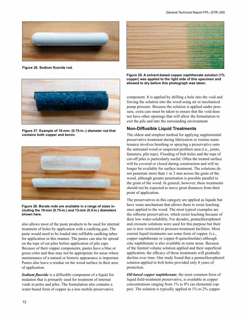
A more challenging maintenance task can be removal of dirt and organic debris that builds up in cracks and crevices over years of service. This organic material helps to trap moisture and provides a source of nutrients for decay fungi in both covered bridges and highway bridges (Figs. 19–22). Unfortunately, this debris tends to accumulate in joints and connections, where the risk of decay is already relatively high. Although it is often not practical to remove all of this material, it is beneficial to remove obvious accumulations.
Types of Supplemental TreatmentsThe objective of supplemental treatment is to distribute preservative into areas of a structure that are vulnerable to
Figure 13. Checks allow ready access for moisture from rain and snow to reach the interior of large timbers. An accumulation of organic matter further increases the potential for decay.
Figure 14. Metal fasteners are sometimes associ-ated with decay pockets if holes are drilled after treatment and expose untreated wood. Field-fab-ricated bolt holes should be field treated with a preservative such as copper naphthenate during construction.
Figure 15. The upper bolt in this pile was either re-moved or never installed. The hole now serves as a ready access for fungi to the untreated interior of the pile.
Figure 16. Unless it was pressure-treated after fabrica-tion, this type of connection is a recipe for decay. It ex-poses untreated wood and creates an area that traps and holds moisture.
Guide for In-Place Treatment of Covered and Timber Bridges
9
moisture accumulation and/or not protected by the original pressure treatment. A major limitation of supplemental treat-ments is that they cannot be forced deep into the wood un-der pressure, as is done in the pressure-treatment processes. Types of supplemental treatments range from finishes to boron rods to fumigants (Table 1).
Water-Diffusible PreservativesWater-diffusible preservatives or diffusible components of preservatives move slowly through water within the wood structure. Water-diffusible preservatives do not “fix” in the wood and thus are able to diffuse through wood as long as sufficient moisture is present (Fig. 23). The distance or ex-tent of diffusion is a function of preservative concentration, wood moisture content, and grain direction. A concentration gradient is needed to drive diffusion, and concentration can become a limiting factor with surface- (spray-) applied sur-face treatments because the volume of actives applied to the
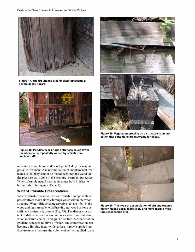
Figure 17. The groundline area of piles represents a severe decay hazard.
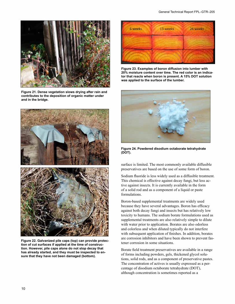
Figure 18. Puddles near bridge entrances cause lower members to be repeatedly wetted by splash from vehicle traffic.
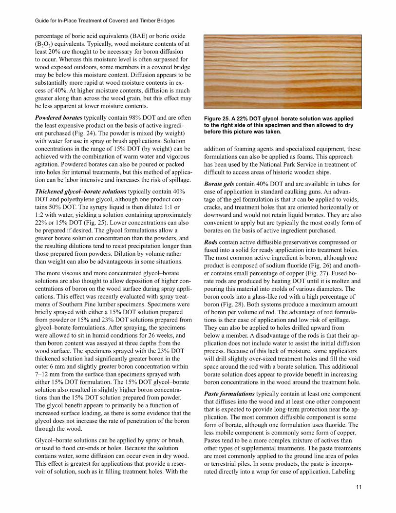
Figure 19. Vegetation growing on a structure is an indi-cation that conditions are favorable for decay.
Figure 20. This type of accumulation of dirt and organic matter makes decay more likely and more rapid if mois-ture reaches this area.
General Technical Report FPL–GTR–205
10
surface is limited. The most commonly available diffusible preservatives are based on the use of some form of boron.
Sodium fluoride is less widely used as a diffusible treatment. This chemical is effective against decay fungi, but less ac-tive against insects. It is currently available in the form of a solid rod and as a component of a liquid or paste formulations.
Boron-based supplemental treatments are widely used because they have several advantages. Boron has efficacy against both decay fungi and insects but has relatively low toxicity to humans. The sodium borate formulations used as supplemental treatments are also relatively simple to dilute with water prior to application. Borates are also odorless and colorless and when diluted typically do not interfere with subsequent application of finishes. In addition, borates are corrosion inhibitors and have been shown to prevent fas-tener corrosion in some situations.
Borate field treatment preservatives are available in a range of forms including powders, gels, thickened glycol solu-tions, solid rods, and as a component of preservative pastes. The concentration of actives is usually expressed as a per-centage of disodium octaborate tetrahydrate (DOT), although concentration is sometimes reported as a
Figure 21. Dense vegetation slows drying after rain and contributes to the deposition of organic matter under and in the bridge.
Figure 22. Galvanized pile caps (top) can provide protec-tion of cut surfaces if applied at the time of construc-tion. However, pile caps alone do not stop decay that has already started, and they must be inspected to en-sure that they have not been damaged (bottom).
Figure 23. Examples of boron diffusion into lumber with 20% moisture content over time. The red color is an indica-tor that reacts when boron is present. A 15% DOT solution was applied to the surface of the lumber.
Figure 24. Powdered disodium octaborate tetrahydrate (DOT).
Guide for In-Place Treatment of Covered and Timber Bridges
11
percentage of boric acid equivalents (BAE) or boric oxide (B2O3) equivalents. Typically, wood moisture contents of at least 20% are thought to be necessary for boron diffusion to occur. Whereas this moisture level is often surpassed for wood exposed outdoors, some members in a covered bridge may be below this moisture content. Diffusion appears to be substantially more rapid at wood moisture contents in ex-cess of 40%. At higher moisture contents, diffusion is much greater along than across the wood grain, but this effect may be less apparent at lower moisture contents.
Powdered borates typically contain 98% DOT and are often the least expensive product on the basis of active ingredi-ent purchased (Fig. 24). The powder is mixed (by weight) with water for use in spray or brush applications. Solution concentrations in the range of 15% DOT (by weight) can be achieved with the combination of warm water and vigorous agitation. Powdered borates can also be poured or packed into holes for internal treatments, but this method of applica-tion can be labor intensive and increases the risk of spillage.
Thickened glycol–borate solutions typically contain 40% DOT and polyethylene glycol, although one product con-tains 50% DOT. The syrupy liquid is then diluted 1:1 or 1:2 with water, yielding a solution containing approximately 22% or 15% DOT (Fig. 25). Lower concentrations can also be prepared if desired. The glycol formulations allow a greater borate solution concentration than the powders, and the resulting dilutions tend to resist precipitation longer than those prepared from powders. Dilution by volume rather than weight can also be advantageous in some situations.
The more viscous and more concentrated glycol–borate solutions are also thought to allow deposition of higher con-centrations of boron on the wood surface during spray appli-cations. This effect was recently evaluated with spray treat-ments of Southern Pine lumber specimens. Specimens were briefly sprayed with either a 15% DOT solution prepared from powder or 15% and 23% DOT solutions prepared from glycol–borate formulations. After spraying, the specimens were allowed to sit in humid conditions for 26 weeks, and then boron content was assayed at three depths from the wood surface. The specimens sprayed with the 23% DOT thickened solution had significantly greater boron in the outer 6 mm and slightly greater boron concentration within 7–12 mm from the surface than specimens sprayed with either 15% DOT formulation. The 15% DOT glycol–borate solution also resulted in slightly higher boron concentra-tions than the 15% DOT solution prepared from powder. The glycol benefit appears to primarily be a function of increased surface loading, as there is some evidence that the glycol does not increase the rate of penetration of the boron through the wood.
Glycol–borate solutions can be applied by spray or brush, or used to flood cut-ends or holes. Because the solution contains water, some diffusion can occur even in dry wood. This effect is greatest for applications that provide a reser-voir of solution, such as in filling treatment holes. With the
addition of foaming agents and specialized equipment, these formulations can also be applied as foams. This approach has been used by the National Park Service in treatment of difficult to access areas of historic wooden ships.
Borate gels contain 40% DOT and are available in tubes for ease of application in standard caulking guns. An advan-tage of the gel formulation is that it can be applied to voids, cracks, and treatment holes that are oriented horizontally or downward and would not retain liquid borates. They are also convenient to apply but are typically the most costly form of borates on the basis of active ingredient purchased.
Rods contain active diffusible preservatives compressed or fused into a solid for ready application into treatment holes. The most common active ingredient is boron, although one product is composed of sodium fluoride (Fig. 26) and anoth-er contains small percentage of copper (Fig. 27). Fused bo-rate rods are produced by heating DOT until it is molten and pouring this material into molds of various diameters. The boron cools into a glass-like rod with a high percentage of boron (Fig. 28). Both systems produce a maximum amount of boron per volume of rod. The advantage of rod formula-tions is their ease of application and low risk of spillage. They can also be applied to holes drilled upward from below a member. A disadvantage of the rods is that their ap-plication does not include water to assist the initial diffusion process. Because of this lack of moisture, some applicators will drill slightly over-sized treatment holes and fill the void space around the rod with a borate solution. This additional borate solution does appear to provide benefit in increasing boron concentrations in the wood around the treatment hole.
Paste formulations typically contain at least one component that diffuses into the wood and at least one other component that is expected to provide long-term protection near the ap-plication. The most common diffusible component is some form of borate, although one formulation uses fluoride. The less mobile component is commonly some form of copper. Pastes tend to be a more complex mixture of actives than other types of supplemental treatments. The paste treatments are most commonly applied to the ground line area of poles or terrestrial piles. In some products, the paste is incorpo-rated directly into a wrap for ease of application. Labeling
Figure 25. A 22% DOT glycol–borate solution was applied to the right side of this specimen and then allowed to dry before this picture was taken.
General Technical Report FPL–GTR–205
12
also allows most of the paste products to be used for internal treatment of holes by application with a caulking gun. The paste would need to be loaded into refillable caulking tubes for application in this manner. The pastes can also be spread on the tops of cut piles before application of pile caps. Because of their copper components, pastes have a blue or green color and thus may not be appropriate for areas where maintenance of a natural or historic appearance is important. Pastes also leave a residue on the wood surface in their area of application.
Sodium fluoride is a diffusible component of a liquid for-mulation that is primarily used for treatment of internal voids in poles and piles. The formulation also contains a water-based form of copper as a less mobile preservative
component. It is applied by drilling a hole into the void and forcing the solution into the wood using air or mechanical pump pressure. Because the solution is applied under pres-sure, extra care must be taken to ensure that the void does not have other openings that will allow the formulation to exit the pile and into the surrounding environment.
Non-Diffusible Liquid TreatmentsThe oldest and simplest method for applying supplemental preservative treatment during fabrication or routine main-tenance involves brushing or spraying a preservative onto the untreated wood or suspected problem area (i.e., joints, fasteners, pile tops). Flooding of bolt holes and the tops of cut-off piles is particularly useful. Often the treated surface will be covered or closed during construction and will no longer be available for surface treatment. The solutions do not penetrate more than 1 or 2 mm across the grain of the wood, although greater penetration is possible parallel to the grain of the wood. In general, however, these treatments should not be expected to move great distances from their point of application.
The preservatives in this category are applied as liquids but have some mechanism that allows them to resist leaching once applied to the wood. The most typical examples are the oilborne preservatives, which resist leaching because of their low water-solubility. For decades, pentachlorophenol and creosote solutions were used for this purpose but their use is now restricted to pressure-treatment facilities. Most current liquid treatments use some form of copper, (i.e., copper naphthenate or copper-8-quinolinolate) although zinc naphthenate is also available in some areas. Because of the limited volume solution applied and their superficial application, the efficacy of these treatments will gradually decline over time. One study found that a pentachlorophenol solution applied to bolt holes provided only 8 years of protection.
Oil-based copper naphthenate, the most common form of liquid field-treatment preservative, is available in copper concentrations ranging from 1% to 8% (as elemental cop-per). The solution is typically applied at 1% to 2% copper
Figure 26. Sodium fluoride rod.
Figure 27. Example of 19-mm- (0.75-in.-) diameter rod that contains both copper and boron.
Figure 28. Borate rods are available in a range of sizes in-cluding the 19-mm (0.75-in.) and 13-mm (0.5-in.) diameters shown here.
Figure 29. A solvent-based copper naphthenate solution (1% copper) was applied to the right side of this specimen and allowed to dry before this photograph was taken.
Guide for In-Place Treatment of Covered and Timber Bridges
13
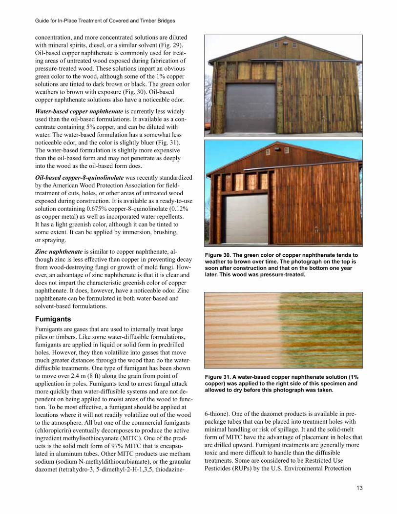
concentration, and more concentrated solutions are diluted with mineral spirits, diesel, or a similar solvent (Fig. 29). Oil-based copper naphthenate is commonly used for treat-ing areas of untreated wood exposed during fabrication of pressure-treated wood. These solutions impart an obvious green color to the wood, although some of the 1% copper solutions are tinted to dark brown or black. The green color weathers to brown with exposure (Fig. 30). Oil-based copper naphthenate solutions also have a noticeable odor.
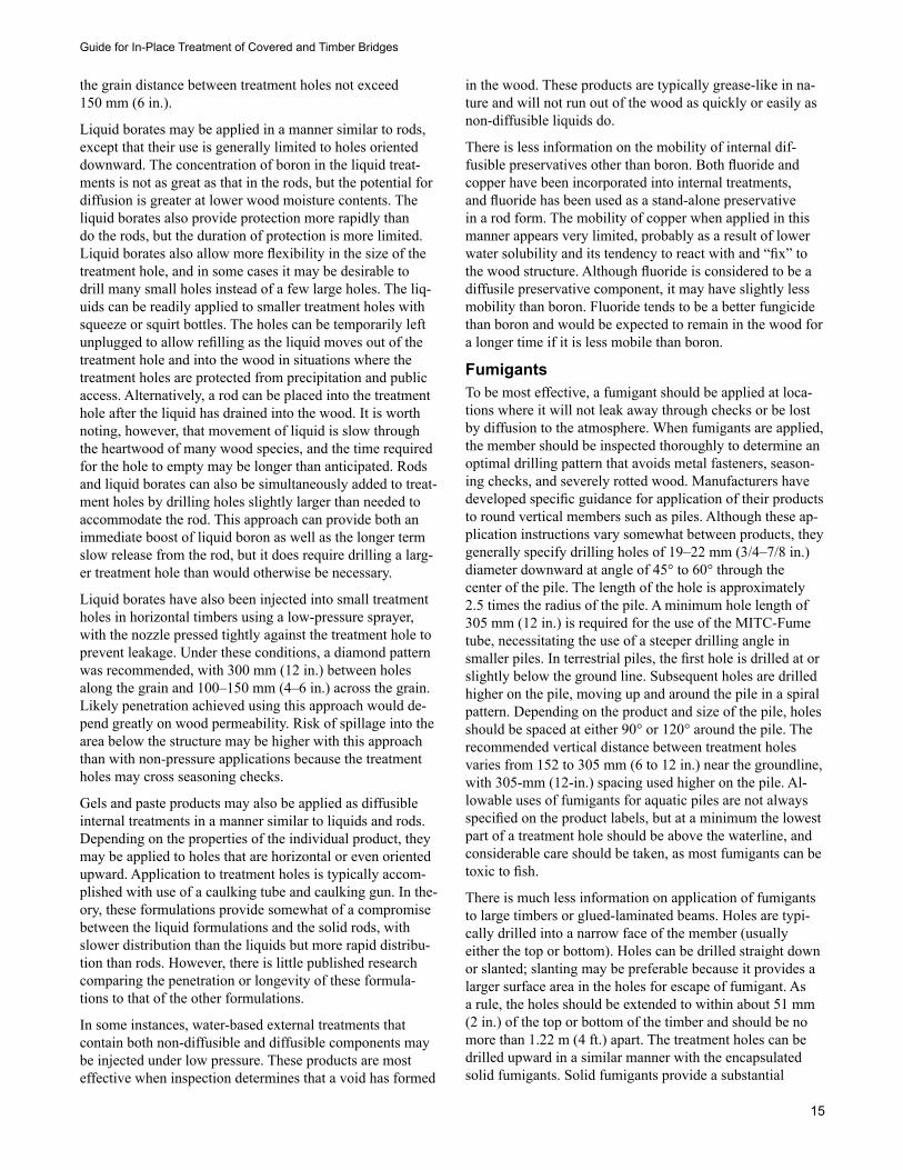
Water-based copper naphthenate is currently less widely used than the oil-based formulations. It available as a con-centrate containing 5% copper, and can be diluted with water. The water-based formulation has a somewhat less noticeable odor, and the color is slightly bluer (Fig. 31). The water-based formulation is slightly more expensive than the oil-based form and may not penetrate as deeply into the wood as the oil-based form does.
Oil-based copper-8-quinolinolate was recently standardized by the American Wood Protection Association for field-treatment of cuts, holes, or other areas of untreated wood exposed during construction. It is available as a ready-to-use solution containing 0.675% copper-8-quinolinolate (0.12% as copper metal) as well as incorporated water repellents. It has a light greenish color, although it can be tinted to some extent. It can be applied by immersion, brushing, or spraying.
Zinc naphthenate is similar to copper naphthenate, al-though zinc is less effective than copper in preventing decay from wood-destroying fungi or growth of mold fungi. How-ever, an advantage of zinc naphthenate is that it is clear and does not impart the characteristic greenish color of copper naphthenate. It does, however, have a noticeable odor. Zinc naphthenate can be formulated in both water-based and solvent-based formulations.
FumigantsFumigants are gases that are used to internally treat large piles or timbers. Like some water-diffusible formulations, fumigants are applied in liquid or solid form in predrilled holes. However, they then volatilize into gasses that move much greater distances through the wood than do the water-diffusible treatments. One type of fumigant has been shown to move over 2.4 m (8 ft) along the grain from point of application in poles. Fumigants tend to arrest fungal attack more quickly than water-diffusible systems and are not de-pendent on being applied to moist areas of the wood to func-tion. To be most effective, a fumigant should be applied at locations where it will not readily volatilize out of the wood to the atmosphere. All but one of the commercial fumigants (chloropicrin) eventually decomposes to produce the active ingredient methylisothiocyanate (MITC). One of the prod-ucts is the solid melt form of 97% MITC that is encapsu-lated in aluminum tubes. Other MITC products use metham sodium (sodium N-methyldithiocarbiamate), or the granular dazomet (tetrahydro-3, 5-dimethyl-2-H-1,3,5, thiodazine-
6-thione). One of the dazomet products is available in pre-package tubes that can be placed into treatment holes with minimal handling or risk of spillage. It and the solid-melt form of MITC have the advantage of placement in holes that are drilled upward. Fumigant treatments are generally more toxic and more difficult to handle than the diffusible treatments. Some are considered to be Restricted Use Pesticides (RUPs) by the U.S. Environmental Protection
Figure 30. The green color of copper naphthenate tends to weather to brown over time. The photograph on the top is soon after construction and that on the bottom one year later. This wood was pressure-treated.
Figure 31. A water-based copper naphthenate solution (1% copper) was applied to the right side of this specimen and allowed to dry before this photograph was taken.

General Technical Report FPL–GTR–205
14
Agency (EPA), requiring extra precautions and application by specially trained personnel.
Liquid fumigants are poured into pre-drilled treatment holes, necessitating that they be applied from above. The most commonly applied liquid fumigant is metham sodium (33% sodium N-methyldithiocarbamate). Like several fu-migants, this liquid formulation decomposes to produce the active ingredient MITC. It tends to be less expensive than other sources of MITC, but also contains a lower proportion of the active ingredient. One of the oldest fumigants, chloro-picrin, is only available in liquid form. It is the most effec-tive, long-lasting fumigant but also difficult to handle safely because of its volatility. It is a RUP and its use is generally confined to critical structures in rural areas.
Granular fumigants are poured into pre-drilled treatment holes in a manner similar to liquids. The current formulations use granular dazomet (98% tetrahydro-3, 5-dimethyl-2-H-1,3,5, thiodazine-6-thione), which decom-poses to produce MITC. The granular fumigant formulations offer relatively easy handling compared with liquid metham sodium and also contain a higher percentage of the active in-gredient. However, they decompose to produce MITC more slowly than the liquids, and in some cases, liquid accelerants such as copper naphthenate (containing 1% copper) are also poured into the treatment hole to promote decomposition.
Encapsulated fumigants are pre-packaged for convenient application and have the added advantage of allowing holes to be drilled from below. In addition to convenience, these encapsulated fumigants minimize the risk of spillage when applications are made over water or any other sensitive environments. One encapsulated product contains the same
granular dazomet that is poured into holes. It is encased in a tube-shaped, air-permeable membrane that contains the par-ticles while allowing MITC gas to escape (Fig. 32). Another encapsulated product consists of an aluminum tube filled with solid 97% MITC (Fig. 33). At the time of application, a special tool is used to remove the air-tight cap from the tube, and MITC vapors are released through this opening. A disadvantage of the encapsulated fumigants is their higher costs and that they require a minimum treatment-hole diameter and depth for application.
Applying Supplemental TreatmentsInternal TreatmentsInternal decay in larger timbers is a function of their ten-dency to check, and for these checks to provide points of water ingress. Wood wets through sorption of liquid water but dries by evaporation of water vapor. As a result, wood almost always wets faster than it dries, particularly far from the surface. This creates elevated, relatively stable mois-ture conditions deeper in the wood. In most cases, bridge members are too thick to effectively treat the interior of the member with surface application of preservatives. Internal treatments are typically applied to these timbers by drilling holes into the wood, but there are many variations on this approach (Table 2).
Water-Diffusible Internal TreatmentsWater-diffusible internal treatments generally do not move to the same extent as do fumigants, and so their application locations and spacing are critical. Although they could be used to treat the length of piles or beams, they may be better suited to protection of specific vulnerable areas such as near pile tops or the groundline, connections, and areas adjacent to fasteners. The extent of movement of these diffusible treatments has been shown to vary with wood moisture con-tent and wood species, although wood moisture content is probably the most important factor. Wood moisture content is typically lower for wood above ground than wood used in ground contact, and studies of boron movement from inter-nal treatments have indicated somewhat limited mobility in above-ground timbers.
Research evaluating the mobility of boron from solid rods in above-ground softwood timbers suggests that rods would need to be placed no more than 50 mm (2 in.) apart across the grain and 300 mm (12 in.) apart along the grain. Some-what tighter spacing may be needed for red oak. Substantial variability in boron mobility has been reported in timbers treated with combinations of liquid and solid internal treatments. However, the results indicate that spacing of approximately 75 mm (3 in.) across the grain and between 75 and 125 mm (3–5 in.) along the grain would be needed to achieve overlapping boron penetration in southern pine tim-bers. The manufacturer of one of the boron rod products rec-ommends parallel to the grain spacing of between 150 and 380 mm (6–15 in.) depending on the size of the timber and the size of the rod installed. They recommend that the across
Figure 32. A granular fumigant pre-packaged in a vapor-permeable membrane.
Figure 33. A solid fumigant encapsulated in a metal tube. The cap is removed at installation.
Guide for In-Place Treatment of Covered and Timber Bridges
15
the grain distance between treatment holes not exceed 150 mm (6 in.).
Liquid borates may be applied in a manner similar to rods, except that their use is generally limited to holes oriented downward. The concentration of boron in the liquid treat-ments is not as great as that in the rods, but the potential for diffusion is greater at lower wood moisture contents. The liquid borates also provide protection more rapidly than do the rods, but the duration of protection is more limited. Liquid borates also allow more flexibility in the size of the treatment hole, and in some cases it may be desirable to drill many small holes instead of a few large holes. The liq-uids can be readily applied to smaller treatment holes with squeeze or squirt bottles. The holes can be temporarily left unplugged to allow refilling as the liquid moves out of the treatment hole and into the wood in situations where the treatment holes are protected from precipitation and public access. Alternatively, a rod can be placed into the treatment hole after the liquid has drained into the wood. It is worth noting, however, that movement of liquid is slow through the heartwood of many wood species, and the time required for the hole to empty may be longer than anticipated. Rods and liquid borates can also be simultaneously added to treat-ment holes by drilling holes slightly larger than needed to accommodate the rod. This approach can provide both an immediate boost of liquid boron as well as the longer term slow release from the rod, but it does require drilling a larg-er treatment hole than would otherwise be necessary.
Liquid borates have also been injected into small treatment holes in horizontal timbers using a low-pressure sprayer, with the nozzle pressed tightly against the treatment hole to prevent leakage. Under these conditions, a diamond pattern was recommended, with 300 mm (12 in.) between holes along the grain and 100–150 mm (4–6 in.) across the grain. Likely penetration achieved using this approach would de-pend greatly on wood permeability. Risk of spillage into the area below the structure may be higher with this approach than with non-pressure applications because the treatment holes may cross seasoning checks.
Gels and paste products may also be applied as diffusible internal treatments in a manner similar to liquids and rods. Depending on the properties of the individual product, they may be applied to holes that are horizontal or even oriented upward. Application to treatment holes is typically accom-plished with use of a caulking tube and caulking gun. In the-ory, these formulations provide somewhat of a compromise between the liquid formulations and the solid rods, with slower distribution than the liquids but more rapid distribu-tion than rods. However, there is little published research comparing the penetration or longevity of these formula-tions to that of the other formulations.
In some instances, water-based external treatments that contain both non-diffusible and diffusible components may be injected under low pressure. These products are most effective when inspection determines that a void has formed
in the wood. These products are typically grease-like in na-ture and will not run out of the wood as quickly or easily as non-diffusible liquids do.
There is less information on the mobility of internal dif-fusible preservatives other than boron. Both fluoride and copper have been incorporated into internal treatments, and fluoride has been used as a stand-alone preservative in a rod form. The mobility of copper when applied in this manner appears very limited, probably as a result of lower water solubility and its tendency to react with and “fix” to the wood structure. Although fluoride is considered to be a diffusile preservative component, it may have slightly less mobility than boron. Fluoride tends to be a better fungicide than boron and would be expected to remain in the wood for a longer time if it is less mobile than boron.
FumigantsTo be most effective, a fumigant should be applied at loca-tions where it will not leak away through checks or be lost by diffusion to the atmosphere. When fumigants are applied, the member should be inspected thoroughly to determine an optimal drilling pattern that avoids metal fasteners, season-ing checks, and severely rotted wood. Manufacturers have developed specific guidance for application of their products to round vertical members such as piles. Although these ap-plication instructions vary somewhat between products, they generally specify drilling holes of 19–22 mm (3/4–7/8 in.) diameter downward at angle of 45° to 60° through the center of the pile. The length of the hole is approximately 2.5 times the radius of the pile. A minimum hole length of 305 mm (12 in.) is required for the use of the MITC-Fume tube, necessitating the use of a steeper drilling angle in smaller piles. In terrestrial piles, the first hole is drilled at or slightly below the ground line. Subsequent holes are drilled higher on the pile, moving up and around the pile in a spiral pattern. Depending on the product and size of the pile, holes should be spaced at either 90° or 120° around the pile. The recommended vertical distance between treatment holes varies from 152 to 305 mm (6 to 12 in.) near the groundline, with 305-mm (12-in.) spacing used higher on the pile. Al-lowable uses of fumigants for aquatic piles are not always specified on the product labels, but at a minimum the lowest part of a treatment hole should be above the waterline, and considerable care should be taken, as most fumigants can be toxic to fish.
There is much less information on application of fumigants to large timbers or glued-laminated beams. Holes are typi-cally drilled into a narrow face of the member (usually either the top or bottom). Holes can be drilled straight down or slanted; slanting may be preferable because it provides a larger surface area in the holes for escape of fumigant. As a rule, the holes should be extended to within about 51 mm (2 in.) of the top or bottom of the timber and should be no more than 1.22 m (4 ft.) apart. The treatment holes can be drilled upward in a similar manner with the encapsulated solid fumigants. Solid fumigants provide a substantial
General Technical Report FPL–GTR–205
16
advantage in treatment of timbers and beams because access is often limited to the bottom face. A disadvantage of the pre-encapsulated fumigants is that they require a minimum size of treatment hole, and thus cannot be used on smaller members.
When treating with fumigants, the treatment hole should be plugged with a tight-fitting treated wood dowel or remov-able plastic plug immediately after application. Sufficient room must remain in the treating hole so the plug can be driven without squirting liquid chemical out of the hole or impacting the solid fumigant. The amount of fumigant needed and the size and number of treating holes required depend on timber size. Fumigants will eventually diffuse out of the wood, allowing decay fungi to recolonize. Additional fumigant can be applied to the same treatment hole, a pro-cess that is made easier with the use of removable plugs.
Fumigants should not be applied into voids or when applica-tion holes intersect voids or checks, thus limiting the risk for accidental release of the product into the environment. Structures where fumigants have been applied should be marked to indicate its presence. Care should be taken in the removal of wood structures that have been treated with solid fumigants to ensure that the chemical has moved out of the treatment hole and into the surrounding wood. Some pro-ducers of solid fumigants have procedures for recovery of their tubes when a structure is removed. Consult the manu-facturers of the formulation for specific information.
Non-Diffusible LiquidsNon-diffusible liquid treatments, typically containing some form of copper, are sometimes used for internal treatments. Although these treatments do not diffuse in water within the wood, they can move for several inches parallel to the wood grain in permeable sapwood. Movement across the grain is minimal. The advantage of these liquids relative to the diffusible treatments is their resistance to leaching. Thus, they may have applications where resistance to weathering is of greater importance than volume of wood protected. An example is bolt holes positioned in a manner that is likely to subject the hole to frequent wetting (in more sheltered locations, a concentrated water-diffusible treatment is likely to provide greater protection). Treatment holes can also be drilled above existing connectors, filled with preservative, and plugged. This type of treatment may be desirable if subsequent fabrication or construction activities will make that area difficult to access in the future. These preservative liquids may be used to flood internal voids such as decay pockets in poles and terrestrial piles, but the risk of spillage may make this type of application less suitable for aquatic applications. In addition, much of the chemical is absorbed by wood that is already decayed rather than adjacent sound wood.
External TreatmentsExternal treatments generally have the greatest applicabil-ity for members that have not been pressure treated, but
also have value in protecting pressure-treated wood when untreated wood is exposed during fabrication. Many of the same formulations used for internal treatments can also be used for external treatment. Protection is generally limited to within a few millimeters of the wood surface although greater movement does occur when solutions are applied to the end-grain of wood. Surface-applied gels, pastes, and water-diffusible treatments can also achieve deeper penetra-tion under some conditions. However, broad-scale surface sprays can be highly problematic from the viewpoint of en-vironmental contamination, and the potential benefits from this approach must be weighed against the risks. In many cases, it may be more practical limit surface applications to localized areas.
Water-diffusible liquid preservatives (borates) are typically applied with low-pressure sprayers or by brushing in smaller areas. The greatest benefit is achieved by flooding checks, cracks, and other openings, potentially allowing diffusion into decay-prone areas where water tends to collect within the wood. Because of this, it is often desirable to apply the solution after a prolonged dry interval, when checking in the wood is at a maximum. Borates applied to the wood surface can be rapidly depleted if the wood is exposed to precipitation or other forms of liquid water. Borate depletion from exposed members can be slowed (but not completely prevented) with application of a water-repellent formulation after the borate treatment has dried. This may necessitate tarping or otherwise protecting the treated members until they have dried sufficiently to allow application of the wa-ter-repellent. Use of preservative-based water repellent (for example containing copper or zinc naphthenate) can provide further protection to the wood surface. This process can be repeated after the wood surface loses its water repellency.
Surface application of non-diffusible liquid treatments is most beneficial in situations where penetration into the wood is less important than resistance to leaching. Perhaps the most obvious example is field-treatment of untreated wood exposed during fabrication of treated wood. Protection of pile tops is especially important, and in these situations a copper-containing solution should be applied to the exposed surface. Zinc naphthenate can also be used if a clear treat-ment is required. As discussed above, the non-diffusible liquids can also be applied after a diffusible treatment to slow leaching of the diffusible preservative and to provide long term protection. For example, a cut pile top can first be treated with a concentrated borate solution, and then treated with and oil-based copper after the borate solution has dried. At least one product uses pads soaked in a copper solution as part of a groundline wrap/bandage system. It is essential that any pile or pole top also be protected with a water shed-ding cap to prevent the wood from checking and allowing water and fungal spores to enter beyond the protected zone.
The most common external use of gels and pastes is in the protection of the ground-line area of support posts or piles as part of a wrap system. Soil is excavated from around the support to a depth of approximately 0.46 m (18 in.) and the
Guide for In-Place Treatment of Covered and Timber Bridges
17
formulation is brushed or troweled onto the exposed wood to form a 3–8-mm- (0.125–0.375-in.-) thick layer that ex-tends 51–76 mm (2–3 in.) above the ground line. The layer of preservative is then covered with a water-impervious wrap to hold the chemical against the wood, and the ex-cavated area is refilled. The diffusible components of the formulation (for example boron) gradually diffuse into the wood, while the less mobile components remain near the wood surface. Although these treatments are primarily used to supplement the groundline area of preservative-treated utility poles, they have also been shown to offer substantial protection to the groundline area of untreated wood. This type of system should not be used in areas where standing water is expected. The same principal can also be used to protect wood above ground that is covered with metal or a simmilar barrier. For example, these products can be spread on to pile tops before flashing is applied, or on the timbers that are subsequently wrapped with metal flashing. Metal flashing can cause moisture to condense between the metal and the wood, so treatment in this area is desirable. How-ever, many of these formulations are not colorless, and pre-servative that wicks along the grain and extends beyond the cover could slightly discolor untreated wood.
Research on the Use of Supplemental Preservative Treatments for Covered BridgesIn 2001, Oregon State University conducted a study funded by the Federal Highway Administration (FHWA), “Iden-tification of Preservative Treatments and Fumigants for Treating Historic Covered Bridges” (project DTFH61-01-C-0059), which included both field and laboratory evalu-ations of remedial preservative treatments. The laboratory research compared the ability of numerous types of internal treatments to move through wood as a function of mois-ture content, wood species, and dosage. Movement of the water-diffusible preservatives BoraCare (boron, Nisus Cor-poration, Rockford, TN), ShellGuard (boron, Perma-Chink Systems, Inc., Knoxville, TN), Tim-bor (boron, Tim-bor Professional, Rockford, TN), CuRap 20 (boron, copper, ISK Biocides, Inc., Memphis,TN), Impel rods (boron, PRG, Inc., Rockville, MD) Cobra rods (boron, copper, Perma-Chink Systems, Inc., Knoxville, TN) and FluRods (fluoride, Os-mose Utilities Services, Inc., Buffalo, NY) was evaluated, as were the fumigants dazomet (methylisothiocyanate), MITC (methylisothiocyanate) and chloropicrin (trichloronitrometh-ane). Preservative mobility was compared for Douglas-fir, Southern Pine, eastern white pine, eastern hemlock, red oak, and white oak, and the diffusibles were evaluated at three wood moisture contents (30%, 60%, and 100%). As ex-pected, movement of the water-diffusible preservatives was strongly related to moisture content, with relatively little diffusion noted at 30% MC. The study noted that because overall moisture contents in covered bridge members will be relatively low, care will be needed to place water-diffusible treatments where they are likely to be
wetted. Diffusion was also positively correlated with concentration of chemical applied, both within and between types of preservatives. Wood species also affected diffusion, with the less permeable wood species having the lowest concentrations of actives at greater distances away from the treatment. This effect was particularly notable for imperme-able white oak heartwood, which had only limited diffusion. Mobile concentrations of fluoride tended to be lower than those of boron, and diffusion of copper was very limited.
The laboratory evaluations revealed that fumigant moved quickly through blocks treated with MITC or chloropic-rin, reaching maximum levels within one week and then declining as the volatile fumigant moved out of small test specimens. In contrast to the diffusible treatments, fumigant levels tended to be higher in the less permeable species such as Douglas-fir than in the highly permeable Southern Pine. This finding indicates that longer intervals between reappli-cation may be appropriate for covered bridges constructed with less permeable species such as Douglas-fir or white oak. Movement of fumigant from the blocks treated with dazomet was much slower, with only very low levels de-tected after one week, and slightly increased levels detected after 4 weeks. However, no fumigant was detected in some species treated with dazomet, and when concentrations were detected they were many times lower than the one-week concentrations observed for the MITC or chloropicrin-treat-ed specimens.
The field portion of the research was conducted by install-ing two internal water-diffusible treatments (boron rods and fluoride rods) and two internal fumigant treatments (MITC and dazomet) in timbers in five covered bridges. The bridges were located in California, Vermont, Wisconsin, and Illinois and included timbers of white pine, spruce, Douglas-fir, and sugar pine. Mobility of the treatments was determined by assaying the treated timbers at 1 and 2 years after treatment. Sampling holes were drilled into the treated members at distances of 30, 60, and 90 cm (fumigant treatments) or 10, 20, 30 cm (water-diffusible treatments) from each side of the treatment hole.
With few exceptions, no movement of boron and fluoride from the rods was detected in the field-treated bridges. Concentrations in assay samples were either not above background levels or not detected. The possible exceptions were low levels of fluoride detected in a few assay samples removed 10 cm from treatment holes after 2 years exposure in the California bridges. The general absence of boron and fluoride in the assay samples is in agreement with the lack of weight loss observed in the rods after 2 years exposure. The poor mobility observed in this study is probably attrib-utable to the low moisture content of the bridge members. The highest moisture content detected in the members when the rods were placed in the bridge was 27%. Although the moisture content in the members likely fluctuates with pre-cipitation events, it appears that moisture was never consis-tently elevated to the point that diffusion could occur from the rods.
General Technical Report FPL–GTR–205
18
In contrast to the water-diffusible treatments, MITC was detected in many of the samples removed from locations adjacent to the MITC treatments holes. Concentrations were generally greatest and most consistently elevated in samples removed from closest (30 cm) to the treatment holes, but elevated concentrations were also detected at distances of 60 and 90 cm. Concentrations detected in samples removed from 4 of the 5 bridges were relatively similar. The high-est concentrations after 1 year were detected in a California bridge located in hot, dry climate, while concentrations detected after 2 years were higher in the northern bridges. Sublimation of solid MITC is faster at higher temperatures and the higher temperatures at the warmer California loca-tion may have accelerated MITC release from the tubes. Weight losses measured after 2 years suggest that nearly all the MITC had been released from tubes at that bridge. In-terestingly, MITC concentrations detected at the other Cali-fornia bridge were notably lower than for the other bridges. The reason for this is unclear, as the MITC weight loss from the tubes at this bridge after 2 years was similar to the other bridges.
None of the wood assay samples corresponding to the dazomet treatments contained detectable concentrations of MITC at any distance, bridge, or time point. Weight loss from the dazomet treatments was also minimal, indicating that little decomposition and release of MITC had occurred after 2 years. Dazomet requires moisture to decompose to MITC, and as with the water-diffusible treatments, the low wood moisture content may have limited the dazeomet’s mobility. Some suppliers recommend addition of accelerants to dazomet treatments to speed decomposition, which was not done in this study. It is possible that greater decomposi-tion would have been observed with the use of these accelerants.
The laboratory and field tests conducted in this study illustrate that movement of preservative away from solid-rod water-diffusible treatments is highly dependent on moisture. Because the majority of covered bridge members are generally dry, the use of these solid water diffusibles would be most efficient if they were closely targeted to loca-tions where moisture is suspected. The use of solid-water-diffusible treatments in covered bridges may also be seen as a type of insurance against future moisture problems. In theory, if these moisture problems do occur, the preserva-tive in the rods would become activated and spread into the moistened area. Movement from the rods could have also have been given an initial boost by adding water or a liquid borate solution (in the case of the boron rod) to the treat-ment hole. Of the two fumigants evaluated, the MITC tube was clearly the most effective at moving into the wood dur-ing this 2-year study. Because MITC and chloropicrin treat-ments do not rely on moisture for their mobility, they have greater potential for movement in dry bridge timbers. MITC from the MITC treatments in this study routinely moved 60 cm (24 in.) from the treatment hole, suggesting that instal-lation of this treatment with a spacing of 120 cm (48 in.)
would provide for adequate protection of members. MITC was also detected at 90 cm (36 in.) from the treatment holes, but the concentrations detected were often below the 20 ug/g thought to be needed to prevent growth by decay fungi. Average MITC concentrations increased during year 2 of the study, suggesting that the treatments will be effec-tive for at least 3 years. Research on utility poles indicates that MITC levels in wood decline gradually over time and fall below effective concentrations 5 to 7 years after treat-ment. In covered bridges, the longevity of the treatment will be less predictable because of the wide range of designs and member dimensions. However, the lack of soil contact for most covered bridge members should also slow fungal colo-nization once the fumigant has dissipated.
In another study directly applicable to timber bridges, re-searchers at Mississippi State University (MSU) evaluated the efficacy of field treatments in protecting timber connec-tions (joints) or pile sections. In the connections study the MSU researchers evaluated the installation of saturated felt pads within the joints, the application of preservatives to the joint surface, and the application of preservatives to holes drilled into the timber near the connection. The joint treat-ments were evaluated on southern pine, red oak, and yellow poplar wood species. The researchers found that pads satu-rated with a solvent based copper naphthenate solution were largely effective in protection the joint area from decay, while pads saturated with a solvent-based water repellent of-fered little protection. The efficacy of treatments applied to holes near the joint varied by wood species. Boron solution, boron rods, copper borate paste and liquid fumigant (33% sodium N-methyldithiocarbamate) all provided substantial protection for red oak, but the copper borate paste was less effective in protecting southern pine. None of the treatments applied to holes were effective in protecting yellow poplar specimens. Borate solution or copper borate paste applied directly to the outer surface of the connection was generally effective in protecting the joints, although the borate solu-tion was much less effective in protecting the yellow poplar specimens. Copper borate paste applied to surface of the joint was the most effective overall treatment.
The MSU researchers also evaluated the protection of un-treated southern pine pile sections with both internal and ex-ternal treatments. The internal treatments (liquid fumigant, boron rods or fluoride rods) were applied to holes drilled into the center of the piles, while the external treatments (copper borate paste, fluoride paste or a pentachlorophenol grease) were applied as groundline wraps. The exterior pastes applied as wraps were generally effective in protect-ing the groundline area of the piles. In contrast, the internal treatments were much less effective, although a combination of fluoride rods and fumigant provided moderate protection. The poor performance of the internal treatments probably resulted from their inability to protect the exterior of the pile, and it should be noted that internal treatments are typi-cally applied to pressure-treated piles that have a protected exterior shell.
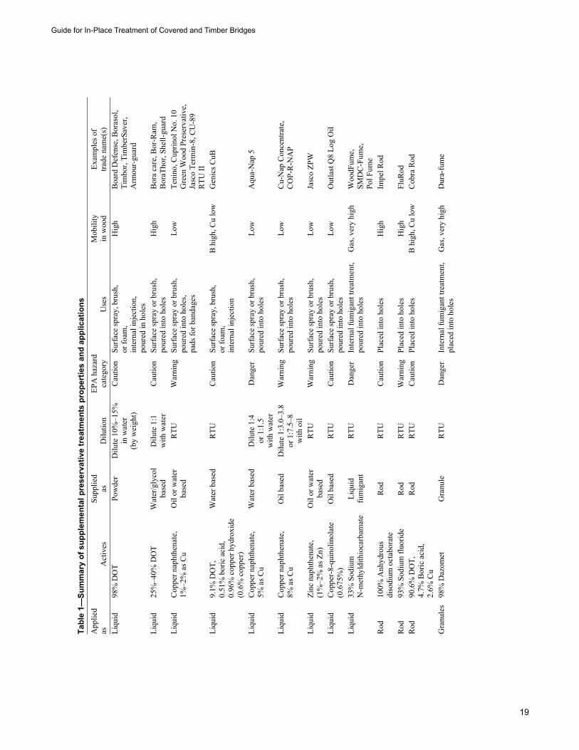
Guide for In-Place Treatment of Covered and Timber Bridges
19
Tabl
e 1—
Sum
mar
y of
sup
plem
enta
l pre
serv
ativ
e tr
eatm
ents
pro
pert
ies
and
appl
icat
ions
A
pplie
d as
Act
ives
Su
pplie
das
D
ilutio
n EP
A h
azar
dca
tego
ry
Use
s M
obili
ty
in w
ood
Exam
ples
of
trade
nam
e(s)
Li
quid
98
% D
OT
Pow
der
Dilu
te 1
0%–1
5%
in w
ater
(b
y w
eigh
t)
Cau
tion
Surf
ace
spra
y, b
rush
, or
foam
, in
tern
al in
ject
ion,
po
ured
in h
oles
Hig
h B
oard
Def
ense
, Bor
asol
, Ti
mbo
r, Ti
mbe
rSav
er,
Arm
our-
guar
d
Liqu
id
25%
–40%
DO
T W
ater
/gly
col
base
d D
ilute
1:1
w
ith w
ater
C
autio
n Su
rfac
e sp
ray
or b
rush
, po
ured
into
hol
es
Hig
h B
ora
care
, Bor
-Ram
, B
oraT
hor,
Shel
l-gua
rd
Liqu
id
Cop
per n
apht
hena
te,
1%–2
% a
s Cu
Oil
or w
ater
base
d R
TU
War
ning
Su
rfac
e sp
ray
or b
rush
, po
ured
into
hol
es,
pads
for b
anda
ges
Low
Te
nino
, Cup
rinol
No.
10
Gre
en W
ood
Pres
erva
tive,
Ja
sco
Term
in-8
, CU
-89
RTU
II
Liqu
id
9.1%
DO
T,
0.51
% b
oric
aci
d,
0.96
% c
oppe
r hyd
roxi
de
(0.6
% c
oppe
r)
Wat
er b
ased
RTU
C
autio
n Su
rfac
e sp
ray,
bru
sh,
or fo
am,
inte
rnal
inje
ctio
n
B h
igh,
Cu
low
Gen
ics C
uB
Liqu
id
Cop
per n
apht
hena
te,
5% a
s Cu
Wat
er b
ased
Dilu
te 1
:4
or 1
:1.5
w
ith w
ater
Dan
ger
Surf
ace
spra
y or
bru
sh,
pour
ed in
to h
oles
Lo
w
Aqu
a-N
ap 5
Liqu
id
Cop
per n
apht
hena
te,
8% a
s Cu
Oil
base
d D
ilute
1:3
.0–3
.8
or 1
:7.5
–8
with
oil
War
ning
Su
rfac
e sp
ray
or b
rush
, po
ured
into
hol
es
Low
C
u-N
ap C
once
ntra
te,
CO
P-R
-NA
P
Liqu
id
Zinc
nap
hthe
nate
, (1
%–2
% a
s Zn)
O
il or
wat
erba
sed
RTU
W
arni
ng
Surf
ace
spra
y or
bru
sh,
pour
ed in
to h
oles
Lo
w
Jasc
o ZP
W
Liqu
id
Cop
per-
8-qu
inol
inol
ate
(0.6
75%
) O
il ba
sed
RTU
C
autio
n Su
rfac
e sp
ray
or b
rush
, po
ured
into
hol
es
Low
O
utla
st Q
8 Lo
g O
il
Liqu
id
33%
Sod
ium
N
-met
hyld
ithio
carb
amat
e Li
quid
fu
mig
ant
RTU
D
ange
r In
tern
al fu
mig
ant t
reat
men
t,po
ured
into
hol
es
Gas
, ver
y hi
ghW
oodF
ume,
SM
DC
-Fum
e,
Pol F
ume
Rod
10
0% A
nhyd
rous
di
sodi
um o
ctab
orat
e R
od
RTU
C
autio
n Pl
aced
into
hol
es
Hig
h Im
pel R
od
Rod
93
% S
odiu
m fl
uorid
e R
odR
TUW
arni
ngPl
aced
into
hol
es
Hig
hFl
uRod
Rod
90
.6%
DO
T,
4.7%
Bor
ic a
cid,
2.
6% C
u
Rod
R
TU
Cau
tion
Plac
ed in
to h
oles
B
hig
h, C
u lo
wC
obra
Rod
Gra
nule
s 98
% D
azom
et
Gra
nule
R
TU
Dan
ger
Inte
rnal
fum
igan
t tre
atm
ent,
plac
ed in
to h
oles
G
as, v
ery
high
Dur
a-fu
me
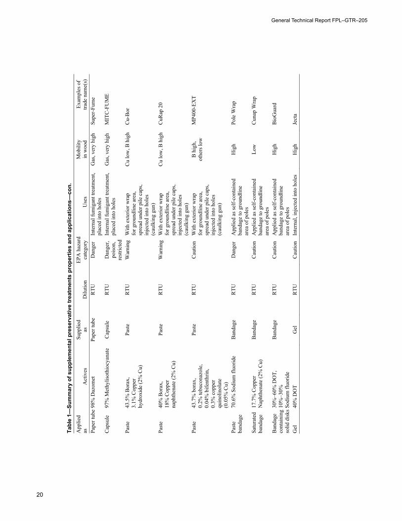
General Technical Report FPL–GTR–205
20
Tabl
e 1—
Sum
mar
y of
sup
plem
enta
l pre
serv
ativ
e tr
eatm
ents
pro
pert
ies
and
appl
icat
ions
—co
n.
App
lied
as
Act
ives
Su
pplie
das
D
ilutio
n EP
A h
azar
dca
tego
ry
Use
s M
obili
ty
in w
ood
Exam
ples
of
trade
nam
e(s)
Pa
per t
ube
98%
Daz
omet
Pa
per t
ube
RTU
D
ange
r In
tern
al fu
mig
ant t
reat
men
t,pl
aced
into
hol
es
Gas
, ver
y hi
ghSu
per-
Fum
e
Cap
sule
97
% M
ethy
lisot
hioc
yana
te
Cap
sule
R
TU
Dan
ger,
pois
on,
rest
ricte
d
Inte
rnal
fum
igan
t tre
atm
ent,
plac
ed in
to h
oles
G
as, v
ery
high
MIT
C-F
UM
E
Past
e 43
.5%
Bor
ax,
3.1%
Cop
per
hydr
oxid
e (2
% C
u)
Past
e R
TU
War
ning
W
ith e
xter
ior w
rap
for g
roun
dlin
e ar
ea,
spre
ad u
nder
pile
cap
s, in
ject
ed in
to h
oles
(c
aulk
ing
gun)
Cu
low
, B h
igh
Cu-
Bor
Past
e 40
% B
orax
, 18
% C
oppe
r na
phth
enat
e (2
% C
u)
Past
e R
TU
War
ning
W
ith e
xter
ior w
rap
for g
roun
dlin
e ar
ea,
spre
ad u
nder
pile
cap
s, in
ject
ed in
to h
oles
(c
aulk
ing
gun)
Cu
low
, B h
igh
CuR
ap 2
0
Past
e 43
.7%
bor
ax,
0.2%
tebu
cona
zole
, 0.
04%
bife
nthr
in,
0.3%
cop
per
quin
olin
olat
e (0
.05%
Cu)
Past
e R
TU
Cau
tion
With
ext
erio
r wra
p fo
r gro
undl
ine
area
, sp
read
und
er p
ile c
aps,
inje
cted
into
hol
es
(cau
lkin
g gu
n)
B h
igh,
ot
hers
low
M
P400
-EX
T
Past
e ba
ndag
e 70
.6%
Sod
ium
fluo
ride
Ban
dage
R
TU
Dan
ger
App
lied
as se
lf-co
ntai
ned
band
age
to g
roun
dlin
e ar
ea o
f pol
es
Hig
h Po
le W
rap
Satu
rate
d ba
ndag
e 17
.7%
Cop
per
Nap
hthe
nate
(2%
Cu)
B
anda
ge
RTU
C
autio
n A
pplie
d as
self-
cont
aine
d ba
ndag
e to
gro
undl
ine
area
of p
oles
Low
C
unap
Wra
p
Ban
dage
co
ntai
ning
so
lid d
isks
30%
–60%
DO
T,
10%
–30%
So
dium
fluo
ride
Ban
dage
R
TU
Cau
tion
App
lied
as se
lf-co
ntai
ned
band
age
to g
roun
dlin
e ar
ea o
f pol
es
Hig
h B
ioG
uard
Gel
40
% D
OT
Gel
R
TU
Cau
tion
Inte
rnal
, inj
ecte
d in
to h
oles
H
igh
Ject
a
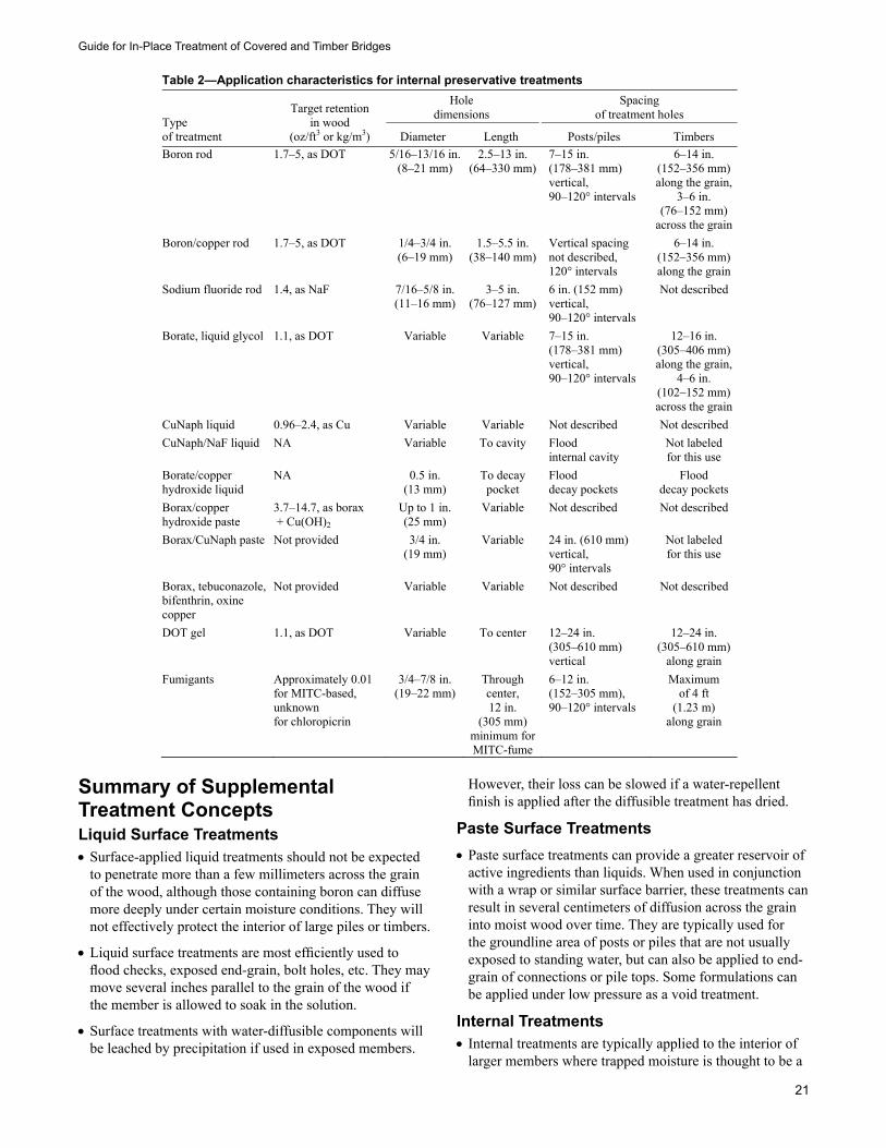
Guide for In-Place Treatment of Covered and Timber Bridges
21
Summary of Supplemental Treatment ConceptsLiquid Surface Treatments•Surface-applied liquid treatments should not be expected
to penetrate more than a few millimeters across the grain of the wood, although those containing boron can diffuse more deeply under certain moisture conditions. They will not effectively protect the interior of large piles or timbers.
•Liquid surface treatments are most efficiently used to flood checks, exposed end-grain, bolt holes, etc. They may move several inches parallel to the grain of the wood if the member is allowed to soak in the solution.
•Surface treatments with water-diffusible components will be leached by precipitation if used in exposed members.
However, their loss can be slowed if a water-repellent finish is applied after the diffusible treatment has dried.
Paste Surface Treatments•Paste surface treatments can provide a greater reservoir of
active ingredients than liquids. When used in conjunction with a wrap or similar surface barrier, these treatments can result in several centimeters of diffusion across the grain into moist wood over time. They are typically used for the groundline area of posts or piles that are not usually exposed to standing water, but can also be applied to end-grain of connections or pile tops. Some formulations can be applied under low pressure as a void treatment.
Internal Treatments•Internal treatments are typically applied to the interior of
larger members where trapped moisture is thought to be a
Table 2—Application characteristics for internal preservative treatments
Typeof treatment
Target retention in wood
(oz/ft3 or kg/m3)
Hole dimensions
Spacing of treatment holes
Diameter Length Posts/piles Timbers Boron rod 1.7–5, as DOT 5/16–13/16 in.
(8–21 mm) 2.5–13 in.
(64–330 mm)7–15 in. (178–381 mm) vertical, 90–120° intervals
6–14 in. (152–356 mm)along the grain,
3–6 in. (76–152 mm)
across the grainBoron/copper rod 1.7–5, as DOT 1/4–3/4 in.
(6–19 mm) 1.5–5.5 in.
(38–140 mm)Vertical spacing not described, 120° intervals
6–14 in. (152–356 mm)along the grain
Sodium fluoride rod 1.4, as NaF 7/16–5/8 in.(11–16 mm)
3–5 in. (76–127 mm)
6 in. (152 mm) vertical, 90–120° intervals
Not described
Borate, liquid glycol 1.1, as DOT Variable Variable 7–15 in. (178–381 mm) vertical, 90–120° intervals
12–16 in. (305–406 mm)along the grain,
4–6 in. (102–152 mm)across the grain
CuNaph liquid 0.96–2.4, as Cu Variable Variable Not described Not described CuNaph/NaF liquid NA Variable To cavity Flood
internal cavity Not labeled for this use
Borate/copper hydroxide liquid
NA 0.5 in. (13 mm)
To decay pocket
Flood decay pockets
Flood decay pockets
Borax/copper hydroxide paste
3.7–14.7, as borax + Cu(OH)2
Up to 1 in. (25 mm)
Variable Not described Not described
Borax/CuNaph paste Not provided 3/4 in. (19 mm)
Variable 24 in. (610 mm) vertical, 90° intervals
Not labeled for this use
Borax, tebuconazole, bifenthrin, oxine copper
Not provided Variable Variable Not described Not described
DOT gel 1.1, as DOT Variable To center 12–24 in. (305–610 mm) vertical
12–24 in. (305–610 mm)
along grain Fumigants Approximately 0.01
for MITC-based, unknown for chloropicrin
3/4–7/8 in. (19–22 mm)
Through center, 12 in.
(305 mm) minimum for MITC-fume
6–12 in. (152–305 mm), 90–120° intervals
Maximum of 4 ft
(1.23 m) along grain
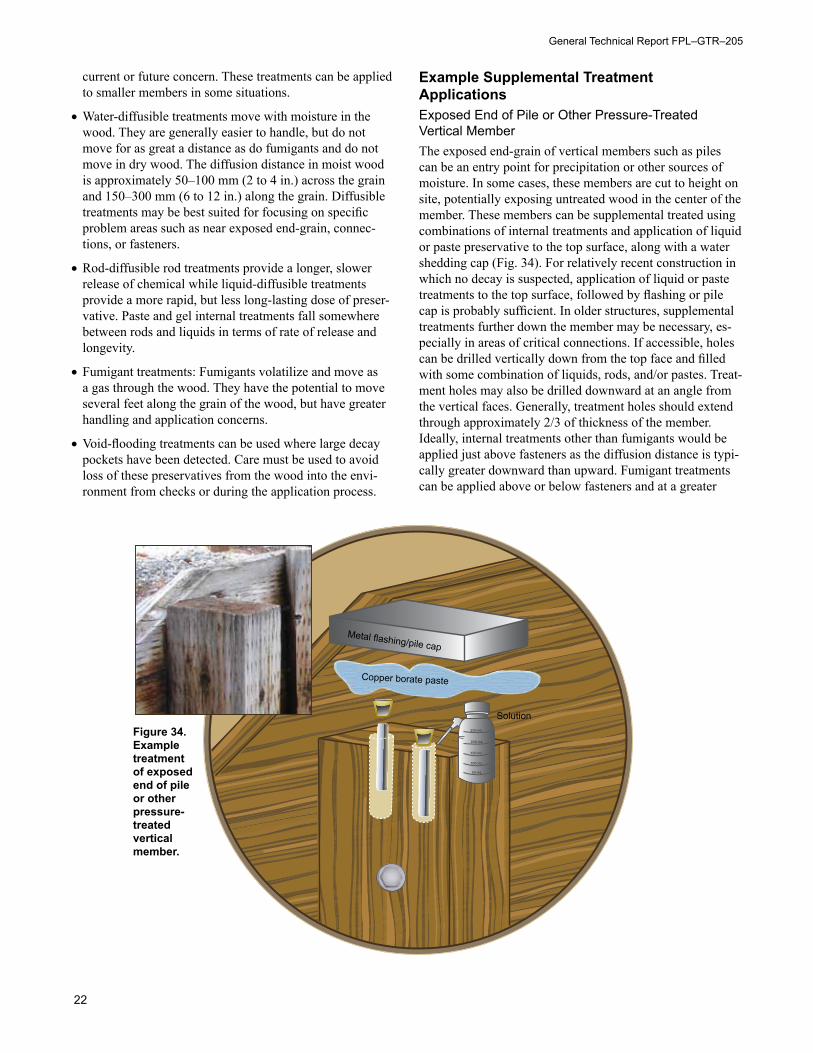
General Technical Report FPL–GTR–205
22
current or future concern. These treatments can be applied to smaller members in some situations.
•Water-diffusible treatments move with moisture in the wood. They are generally easier to handle, but do not move for as great a distance as do fumigants and do not move in dry wood. The diffusion distance in moist wood is approximately 50–100 mm (2 to 4 in.) across the grain and 150–300 mm (6 to 12 in.) along the grain. Diffusible treatments may be best suited for focusing on specific problem areas such as near exposed end-grain, connec-tions, or fasteners.
•Rod-diffusible rod treatments provide a longer, slower release of chemical while liquid-diffusible treatments provide a more rapid, but less long-lasting dose of preser-vative. Paste and gel internal treatments fall somewhere between rods and liquids in terms of rate of release and longevity.
•Fumigant treatments: Fumigants volatilize and move as a gas through the wood. They have the potential to move several feet along the grain of the wood, but have greater handling and application concerns.
•Void-flooding treatments can be used where large decay pockets have been detected. Care must be used to avoid loss of these preservatives from the wood into the envi-ronment from checks or during the application process.
Example Supplemental Treatment Applications Exposed End of Pile or Other Pressure-Treated Vertical Member The exposed end-grain of vertical members such as piles can be an entry point for precipitation or other sources of moisture. In some cases, these members are cut to height on site, potentially exposing untreated wood in the center of the member. These members can be supplemental treated using combinations of internal treatments and application of liquid or paste preservative to the top surface, along with a water shedding cap (Fig. 34). For relatively recent construction in which no decay is suspected, application of liquid or paste treatments to the top surface, followed by flashing or pile cap is probably sufficient. In older structures, supplemental treatments further down the member may be necessary, es-pecially in areas of critical connections. If accessible, holes can be drilled vertically down from the top face and filled with some combination of liquids, rods, and/or pastes. Treat-ment holes may also be drilled downward at an angle from the vertical faces. Generally, treatment holes should extend through approximately 2/3 of thickness of the member. Ideally, internal treatments other than fumigants would be applied just above fasteners as the diffusion distance is typi-cally greater downward than upward. Fumigant treatments can be applied above or below fasteners and at a greater
Solution
Metal flashing/pile cap
Copper borate paste
250 mL
200 mL
150 mL
100 mL
50 mL
Figure 34. Example treatment of exposed end of pile or other pressure-treated vertical member.
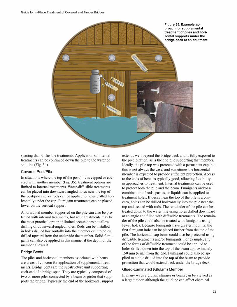
Guide for In-Place Treatment of Covered and Timber Bridges
23
spacing than diffusible treatments. Application of internal treatments can be continued down the pile to the water or soil line (Fig. 34).
Covered Post/PileIn situations where the top of the post/pile is capped or cov-ered with another member (Fig. 35), treatment options are limited to internal treatments. Water-diffusible treatments can be placed into downward angled holes near the top of the post/pile cap, or rods can be applied to holes drilled hor-izontally under the cap. Fumigant treatments can be placed lower on the vertical support.
A horizontal member supported on the pile can also be pro-tected with internal treatments, but solid treatments may be the most practical option if limited access does not allow drilling of downward-angled holes. Rods can be installed in holes drilled horizontally into the member or into holes drilled upward from the underside the member. Solid fumi-gants can also be applied in this manner if the depth of the member allows it.
Bridge Bents The piles and horizontal members associated with bents are areas of concern for application of supplemental treat-ments. Bridge bents are the substructure unit supporting each end of a bridge span. They are typically composed of two or more piles connected by a beam or girder that supp-ports the bridge. Typically the end of the horizontal support
extends well beyond the bridge deck and is fully exposed to the precipitation, as is the end pile supporting that member. Ideally, the pile top was protected with a permanent cap, but this is not always the case, and sometimes the horizontal member is expected to provide sufficient protection. Access to the ends of bents is typically good, allowing flexibility in approaches to treatment. Internal treatments can be used to protect both the pile and the beam. Fumigants and/or a combination of rods, pastes, or liquids can be applied to treatment holes. If decay near the top of the pile is a con-cern, holes can be drilled horizontally into the pile near the top and treated with rods. The remainder of the pile can be treated down to the water line using holes drilled downward at an angle and filled with diffusible treatments. The remain-der of the pile could also be treated with fumigants using fewer holes. Because fumigants have greater mobility, the first fumigant hole can be placed further from the top of the pile. The horizontal cap beam could also be protected using diffusible treatments and/or fumigants. For example, any of the forms of diffusible treatment could be applied to holes drilled down into the top of the beam approximately 150 mm (6 in.) from the end. Fumigant could also be ap-plied to a hole drilled into the top of the beam to provide protection that would extend back under the bridge deck.
Glued-Laminated (Glulam) MemberIn many ways a glulam stringer or beam can be viewed as a large timber, although the glueline can affect chemical
250 mL
200 mL
150 mL
100 mL
50 mL
Figure 35. Example ap-proach for supplemental treatment of piles and hori-zontal supports under the bridge deck at an abutment.
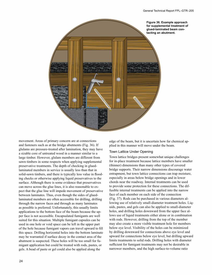
General Technical Report FPL–GTR–205
24
movement. Areas of primary concern are at connections and fasteners such as at the bridge abutments (Fig. 36). If glulams are pressure-treated after lamination, they may have a sizable core of untreated wood in a manner similar to a large timber. However, glulam members are different from sawn timbers in some respects when applying supplemental preservative treatments. The depth of checking in glued-laminated members in service is usually less than that in solid-sawn timbers, and there is typically less value in flood-ing checks or otherwise applying liquid preservatives to the surface. Although there is some evidence that preservatives can move across the glue lines, it is also reasonable to ex-pect that the glue line will impede movement of preservative between laminates. Thus, even though the sides of glued-laminated members are often accessible for drilling, drilling through the narrow faces and through as many laminates as possible is preferred. Unfortunately, this usually limits applications to the bottom face of the beam because the up-per face is not accessible. Encapsulated fumigants are well suited for this situation. Multiple fumigant capsules can be used in one hole or void space can be left in the upper part of the hole because fumigant vapors can travel upward to fill this space. Drilling horizontal holes into the bottom laminate may be warranted if surface decay in the contact area of the abutment is suspected. These holes will be too small for fu-migant application but could be treated with rods, pastes, or gels. A bead of paste or gel could also be applied along the
edge of the beam, but it is uncertain how far chemical ap-plied in this manner will move under the beam.
Town Lattice Under OpeningTown lattice bridges present somewhat unique challenges for in-place treatment because lattice members have smaller (thinner) dimensions than many other types of covered bridge supports. Their narrow dimensions discourage water entrapment, but town lattice connections can trap moisture, especially in areas below bridge openings and in lower chords near the roadway. Internal treatments can be used to provide some protection for these connections. The dif-fusible internal treatments can be applied into the narrow face of each member on each side of the connection (Fig. 37). Rods can be purchased in various diameters al-lowing use of relatively small-diameter treatment holes. Liq-uids, pastes, and gels can also be applied to small-diameter holes, and drilling holes downward from the upper face al-lows use of liquid treatments either alone or in combination with rods. However, drilling from the top of the member may also create a more visible treatment hole for members below eye level. Visibility of the holes can be minimized by drilling downward for connections above eye level and upward for connections below eye level, but drilling upward limits treatments to solid rods. Drilling holes with diameter sufficient for fumigant treatments may not be desirable in narrower members, and the high surface-to-volume ratio
Figure 36. Example approach for supplemental treatment of glued-laminated beam con-tacting an abutment.
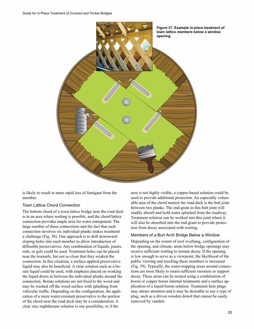
Guide for In-Place Treatment of Covered and Timber Bridges
25
is likely to result in more rapid loss of fumigant from the member.
Town Lattice Chord ConnectionThe bottom chord of a town lattice bridge near the road deck is in an area where wetting is possible, and the chord/lattice connection provides ample area for water entrapment. The large number of these connections and the fact that each connection involves six individual planks makes treatment a challenge (Fig. 38). One approach is to drill downward-sloping holes into each member to allow introduction of diffusible preservatives. Any combination of liquids, pastes, rods, or gels could be used. Treatment holes can be placed near the treenails, but not so close that they weaken the connection. In this situation, a surface-applied preservative liquid may also be beneficial. A clear solution such as a bo-rate liquid could be used, with emphasis placed on working the liquid down in between the individual planks around the connection. Borate solutions are not fixed to the wood and may be washed off the wood surface with splashing from vehicular traffic. Depending on the configuration, the appli-cation of a more water-resistant preservative to the portion of the chord near the road deck may be a consideration. A clear zinc naphthenate solution is one possibility, or if the
area is not highly visible, a copper-based solution could be used to provide additional protection. An especially vulner-able area of the chord nearest the road deck is the butt joint between two planks. The end-grain in this butt joint will readily absorb and hold water splashed from the roadway. Treatment solution can be worked into this joint where it will also be absorbed into the end-grain to provide protec-tion from decay associated with wetting.
Members of a Burr Arch Bridge Below a Window Depending on the extent of roof overhang, configuration of the opening, and climate, areas below bridge openings may receive sufficient wetting to sustain decay. If the opening is low enough to serve as a viewpoint, the likelihood of the public viewing and touching these members is increased (Fig. 39). Typically, the water-trapping areas around connec-tions are most likely to retain sufficient moisture to support decay. These areas can be treated using a combination of boron or copper boron internal treatments and a surface ap-plication of a liquid boron solution. Treatment hole plugs may attract attention and it may be desirable to use a type of plug, such as a driven wooden dowel that cannot be easily removed by vandals.
250 mL
200 mL
150 mL
100 mL
50 mL
Figure 37. Example in-place treatment of town lattice members below a window opening.
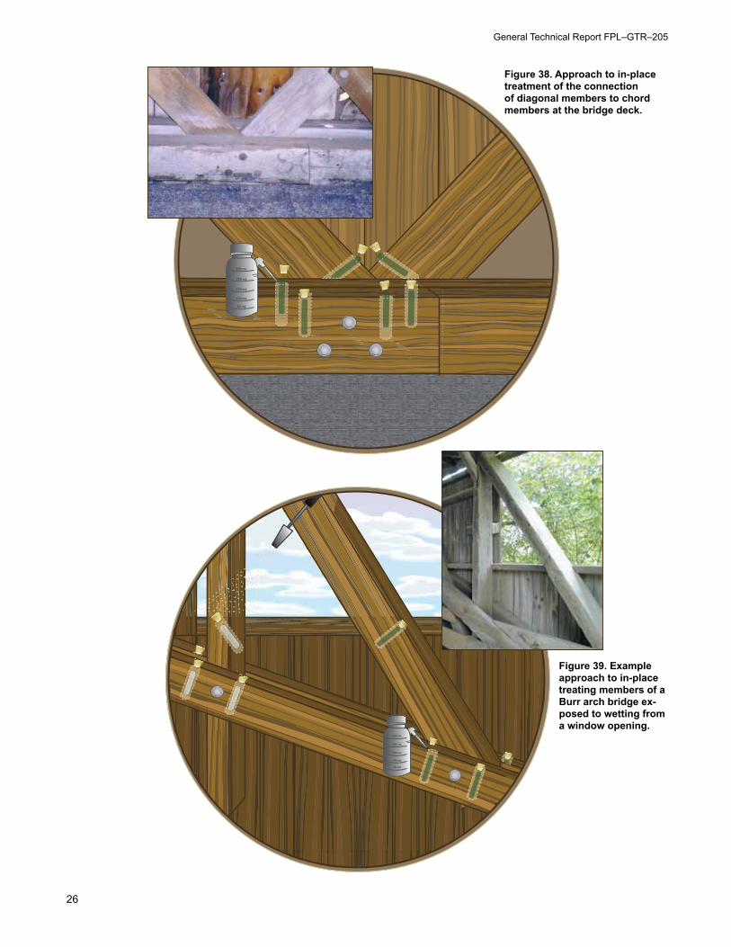
General Technical Report FPL–GTR–205
26
250 mL
200 mL
150 mL
100 mL
50 mL
Figure 38. Approach to in-place treatment of the connection of diagonal members to chord members at the bridge deck.
250 mL
200 mL
150 mL
100 mL
50 mL
Figure 39. Example approach to in-place treating members of a Burr arch bridge ex-posed to wetting from a window opening.
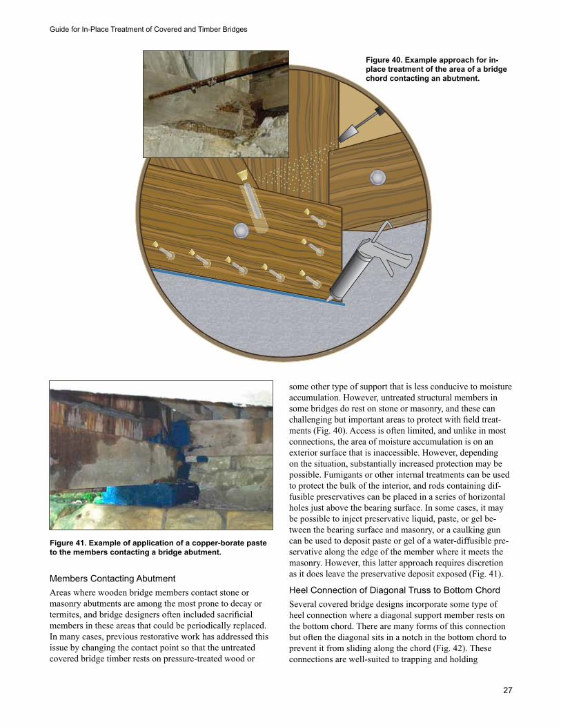
Guide for In-Place Treatment of Covered and Timber Bridges
27
Members Contacting AbutmentAreas where wooden bridge members contact stone or masonry abutments are among the most prone to decay or termites, and bridge designers often included sacrificial members in these areas that could be periodically replaced. In many cases, previous restorative work has addressed this issue by changing the contact point so that the untreated covered bridge timber rests on pressure-treated wood or
some other type of support that is less conducive to moisture accumulation. However, untreated structural members in some bridges do rest on stone or masonry, and these can challenging but important areas to protect with field treat-ments (Fig. 40). Access is often limited, and unlike in most connections, the area of moisture accumulation is on an exterior surface that is inaccessible. However, depending on the situation, substantially increased protection may be possible. Fumigants or other internal treatments can be used to protect the bulk of the interior, and rods containing dif-fusible preservatives can be placed in a series of horizontal holes just above the bearing surface. In some cases, it may be possible to inject preservative liquid, paste, or gel be-tween the bearing surface and masonry, or a caulking gun can be used to deposit paste or gel of a water-diffusible pre-servative along the edge of the member where it meets the masonry. However, this latter approach requires discretion as it does leave the preservative deposit exposed (Fig. 41).
Heel Connection of Diagonal Truss to Bottom ChordSeveral covered bridge designs incorporate some type of heel connection where a diagonal support member rests on the bottom chord. There are many forms of this connection but often the diagonal sits in a notch in the bottom chord to prevent it from sliding along the chord (Fig. 42). These connections are well-suited to trapping and holding
Figure 40. Example approach for in-place treatment of the area of a bridge chord contacting an abutment.
Figure 41. Example of application of a copper-borate paste to the members contacting a bridge abutment.
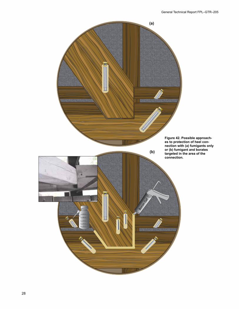
General Technical Report FPL–GTR–205
28
250 mL
200 mL
150 mL
100 mL
50 mL
Figure 42. Possible approach-es to protection of heel con-nection with (a) fumigants only or (b) fumigant and borates targeted in the area of the connection.
(a)
(b)
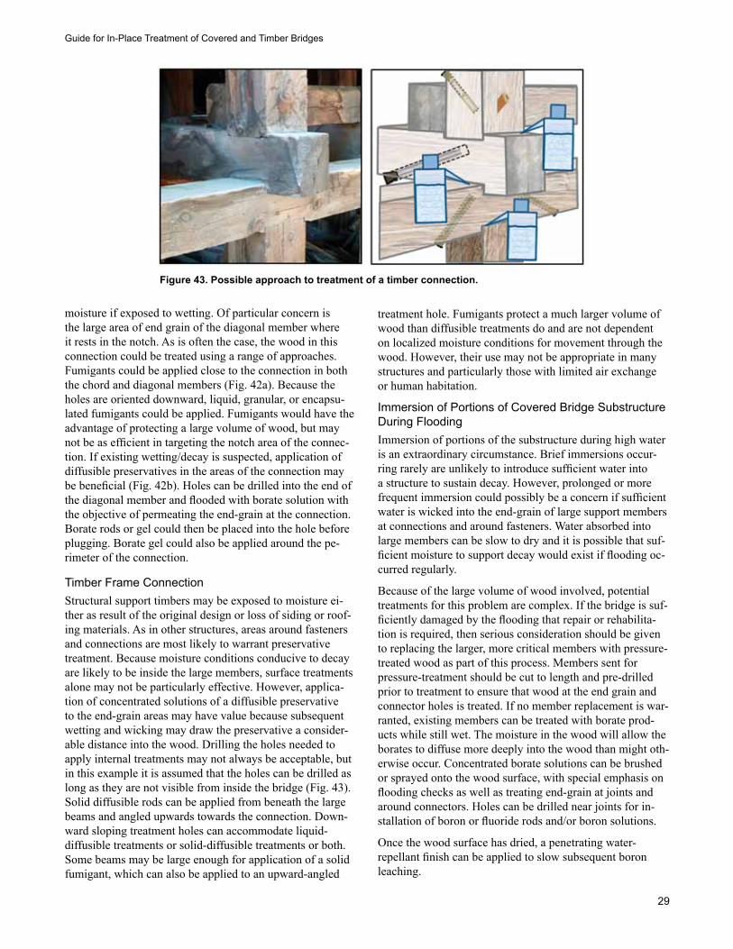
Guide for In-Place Treatment of Covered and Timber Bridges
29
moisture if exposed to wetting. Of particular concern is the large area of end grain of the diagonal member where it rests in the notch. As is often the case, the wood in this connection could be treated using a range of approaches. Fumigants could be applied close to the connection in both the chord and diagonal members (Fig. 42a). Because the holes are oriented downward, liquid, granular, or encapsu-lated fumigants could be applied. Fumigants would have the advantage of protecting a large volume of wood, but may not be as efficient in targeting the notch area of the connec-tion. If existing wetting/decay is suspected, application of diffusible preservatives in the areas of the connection may be beneficial (Fig. 42b). Holes can be drilled into the end of the diagonal member and flooded with borate solution with the objective of permeating the end-grain at the connection. Borate rods or gel could then be placed into the hole before plugging. Borate gel could also be applied around the pe-rimeter of the connection.
Timber Frame ConnectionStructural support timbers may be exposed to moisture ei-ther as result of the original design or loss of siding or roof-ing materials. As in other structures, areas around fasteners and connections are most likely to warrant preservative treatment. Because moisture conditions conducive to decay are likely to be inside the large members, surface treatments alone may not be particularly effective. However, applica-tion of concentrated solutions of a diffusible preservative to the end-grain areas may have value because subsequent wetting and wicking may draw the preservative a consider-able distance into the wood. Drilling the holes needed to apply internal treatments may not always be acceptable, but in this example it is assumed that the holes can be drilled as long as they are not visible from inside the bridge (Fig. 43). Solid diffusible rods can be applied from beneath the large beams and angled upwards towards the connection. Down-ward sloping treatment holes can accommodate liquid-diffusible treatments or solid-diffusible treatments or both. Some beams may be large enough for application of a solid fumigant, which can also be applied to an upward-angled
treatment hole. Fumigants protect a much larger volume of wood than diffusible treatments do and are not dependent on localized moisture conditions for movement through the wood. However, their use may not be appropriate in many structures and particularly those with limited air exchange or human habitation.
Immersion of Portions of Covered Bridge Substructure During Flooding Immersion of portions of the substructure during high water is an extraordinary circumstance. Brief immersions occur-ring rarely are unlikely to introduce sufficient water into a structure to sustain decay. However, prolonged or more frequent immersion could possibly be a concern if sufficient water is wicked into the end-grain of large support members at connections and around fasteners. Water absorbed into large members can be slow to dry and it is possible that suf-ficient moisture to support decay would exist if flooding oc-curred regularly.
Because of the large volume of wood involved, potential treatments for this problem are complex. If the bridge is suf-ficiently damaged by the flooding that repair or rehabilita-tion is required, then serious consideration should be given to replacing the larger, more critical members with pressure-treated wood as part of this process. Members sent for pressure-treatment should be cut to length and pre-drilled prior to treatment to ensure that wood at the end grain and connector holes is treated. If no member replacement is war-ranted, existing members can be treated with borate prod-ucts while still wet. The moisture in the wood will allow the borates to diffuse more deeply into the wood than might oth-erwise occur. Concentrated borate solutions can be brushed or sprayed onto the wood surface, with special emphasis on flooding checks as well as treating end-grain at joints and around connectors. Holes can be drilled near joints for in-stallation of boron or fluoride rods and/or boron solutions.
Once the wood surface has dried, a penetrating water- repellant finish can be applied to slow subsequent boron leaching.
Figure 43. Possible approach to treatment of a timber connection.
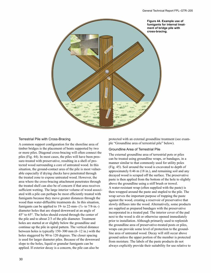
General Technical Report FPL–GTR–205
30
Terrestrial Pile with Cross-BracingA common support configuration for the shoreline area of timber bridges is the placement of bents supported by two or more piles. Diagonal cross-bracing will often connect the piles (Fig. 44). In most cases, the piles will have been pres-sure-treated with preservative, resulting in a shell of pro-tected wood surrounding a core of untreated wood. In this situation, the ground-contact area of the pile is most vulner-able especially if drying checks have penetrated through the treated zone to expose untreated wood. However, the area where the cross-bracing attachment penetrates through the treated shell can also be of concern if that area receives sufficient wetting. The large interior volume of wood associ-ated with a pile can perhaps be most efficiently treated with fumigants because they move greater distances through the wood than water-diffusible treatments do. In this situation, fumigants can be applied to 19- to 22-mm- (¾- to 7/8-in.-) diameter holes that are sloped downward at an angle of 45° to 65°. The holes should extend through the center of the pile and to about 2/3 of the pile diameter. Treatment holes are started at or slightly below the groundline and continue up the pile in spiral pattern. The vertical distance between holes is typically 150–300 mm (6–12 in.) with the holes staggered by 90 to 120 degrees. The closer spacing is used for larger diameter piles. Because of the downward slope to the holes, liquid or granular fumigants can be applied. If exterior decay is a concern, the pile can also be
protected with an external groundline treatment (see exam-ple “Groundline area of terrestrial pile” below).
Groundline Area of Terrestrial PileThe external groundline area of terrestrial pots or piles can be treated using groundline wraps, or bandages, in a manner similar to that commonly used for utility poles (Fig. 45). Soil around the wood is excavated to depth of approximately 0.46 m (18 in.), and remaining soil and any decayed wood is scraped off the surface. The preservative paste is then applied from the bottom of the hole to slightly above the groundline using a stiff brush or trowel. A water-resistant wrap (often supplied with the paste) is then wrapped around the paste and stapled to the pile. The wrap serves the important purpose of trapping the paste against the wood, creating a reservoir of preservative that slowly diffuses into the wood. Alternatively, some products are supplied as prepared bandages with the preservative incorporated in a treated pad. The interior cover of the pad next to the wood is slit or otherwise opened immediately prior to installation. Although primarily used to replenish the groundline area of preservative-treated posts or piles, wraps can provide some level of protection to the ground-line area of untreated wood. Decay will still occur above ground unless the upper portion of the member is protected from moisture. The labels of the paste products do not always explicitly provide their suitability for use relative to
Figure 44. Example use of fumigants for internal treat-ment of bridge pile with cross-bracing.
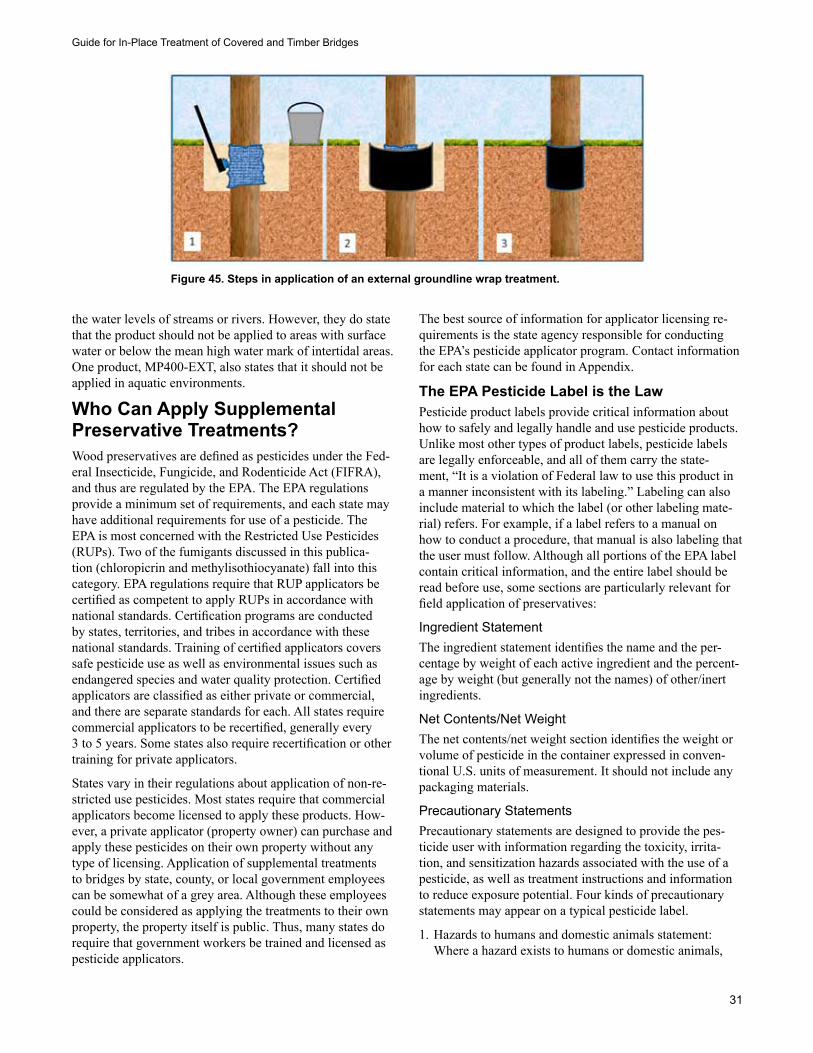
Guide for In-Place Treatment of Covered and Timber Bridges
31
the water levels of streams or rivers. However, they do state that the product should not be applied to areas with surface water or below the mean high water mark of intertidal areas. One product, MP400-EXT, also states that it should not be applied in aquatic environments.
Who Can Apply Supplemental Preservative Treatments?Wood preservatives are defined as pesticides under the Fed-eral Insecticide, Fungicide, and Rodenticide Act (FIFRA), and thus are regulated by the EPA. The EPA regulations provide a minimum set of requirements, and each state may have additional requirements for use of a pesticide. The EPA is most concerned with the Restricted Use Pesticides (RUPs). Two of the fumigants discussed in this publica-tion (chloropicrin and methylisothiocyanate) fall into this category. EPA regulations require that RUP applicators be certified as competent to apply RUPs in accordance with national standards. Certification programs are conducted by states, territories, and tribes in accordance with these national standards. Training of certified applicators covers safe pesticide use as well as environmental issues such as endangered species and water quality protection. Certified applicators are classified as either private or commercial, and there are separate standards for each. All states require commercial applicators to be recertified, generally every 3 to 5 years. Some states also require recertification or other training for private applicators.
States vary in their regulations about application of non-re-stricted use pesticides. Most states require that commercial applicators become licensed to apply these products. How-ever, a private applicator (property owner) can purchase and apply these pesticides on their own property without any type of licensing. Application of supplemental treatments to bridges by state, county, or local government employees can be somewhat of a grey area. Although these employees could be considered as applying the treatments to their own property, the property itself is public. Thus, many states do require that government workers be trained and licensed as pesticide applicators.
The best source of information for applicator licensing re-quirements is the state agency responsible for conducting the EPA’s pesticide applicator program. Contact information for each state can be found in Appendix.
The EPA Pesticide Label is the LawPesticide product labels provide critical information about how to safely and legally handle and use pesticide products. Unlike most other types of product labels, pesticide labels are legally enforceable, and all of them carry the state-ment, “It is a violation of Federal law to use this product in a manner inconsistent with its labeling.” Labeling can also include material to which the label (or other labeling mate-rial) refers. For example, if a label refers to a manual on how to conduct a procedure, that manual is also labeling that the user must follow. Although all portions of the EPA label contain critical information, and the entire label should be read before use, some sections are particularly relevant for field application of preservatives:
Ingredient StatementThe ingredient statement identifies the name and the per-centage by weight of each active ingredient and the percent-age by weight (but generally not the names) of other/inert ingredients.
Net Contents/Net WeightThe net contents/net weight section identifies the weight or volume of pesticide in the container expressed in conven-tional U.S. units of measurement. It should not include any packaging materials.
Precautionary StatementsPrecautionary statements are designed to provide the pes-ticide user with information regarding the toxicity, irrita-tion, and sensitization hazards associated with the use of a pesticide, as well as treatment instructions and information to reduce exposure potential. Four kinds of precautionary statements may appear on a typical pesticide label.
1. Hazards to humans and domestic animals statement: Where a hazard exists to humans or domestic animals,
Figure 45. Steps in application of an external groundline wrap treatment.
General Technical Report FPL–GTR–205
32
precautionary statements that describe the particular haz-ard, route of exposure, and precautions to be taken must appear on the label.
2. First aid statement: This section of the label provides information to the pesticide user concerning appropriate first aid for the various routes of exposure associated with accidental exposure. If the first aid statement appears on the back panel, then there must be a statement on the front panel indicating that first aid information can be found on the back panel.
3. Environmental hazards statement: Where a hazard exists to non-target organisms, precautionary statements that identify the hazards and necessary precautions must ap-pear on the label.
4. Physical or chemical hazards statement: Hazards such as flammability, explosive potential, or electric insula-tor breakdown, as well as the various precautions to be taken, must be identified, as applicable.
Directions for UseDirections for use provide instructions to the user on how to use the product and identifies the pest(s) to be controlled, the application sites, application rates, and any required ap-plication equipment. Just as importantly, this section also includes a use-restrictions statement. General (non-site-spe-cific) precautions, restrictions, or limitations of the product are stated, as are any precautions and restrictions that apply to specific sites. An endangered species statement may also be included if applicable.
Worker ProtectionThe worker protection section provides information for the applicator to minimize their potential exposure to the supplemental treatment. The four types of worker protection statements that generally appear in the precautionary state-ments include the following:
1. Handler personal protective equipment (PPE) statement: Addresses handler PPE requirements such as gloves and safety glasses.
2. User safety requirement statements that address how to handle contaminated PPE: Provides instructions for cleaning and maintaining PPE, and sometimes for dispos-ing of heavily contaminated PPE.
3. Engineering controls statement: Describes any reductions or modifications to handler PPE requirements that may be made in the presence of certain engineering controls (e.g., closed systems, enclosed cabs, lock and load containers).
4. User safety recommendations: Provides additional user safety information.
Storage and Disposal InstructionsStorage and disposal instructions provide instructions for storing the pesticide product and for disposing of any un-used pesticide and the pesticide container.
Collection of Drill ShavingsWhen holes are drilled into pressure-treated wood to apply internal treatments, the resulting shavings contain preser-vative treatment. Because of their greater surface area to volume ratio, preservative leaching from these shavings is many times greater than from the treated wood itself. If the shavings generated during construction are allowed to enter the water below a treated wood structure, they make a disproportionately large contribution to the overall preserva-tive release from that structure. However, this concern can be minimized if reasonable efforts are made to collect the shavings. Many approaches can minimize discharge of drill shavings into the environment. Tarps are commonly used and may be the most practical approach for collecting shav-ings from large numbers of treatment holes. However, the use of tarps becomes more difficult under windy or rainy conditions. Plastic bags, tubs, or trays are also useful collec-tion devices for collecting shavings from individual treat-ment holes, and vacuum cleaners are also sometimes used. Regardless of the method used, it is inevitable that collec-tion of construction debris will add some time and expense to a field treatment project. The importance of collection should be stressed in planning and budgeting for the project so that the application crew is clear that debris collection is an integral part of the job.
Fire PreventionFire is another serious threat for covered bridges and is a leading cause of loss and damage. Although some fires are accidental, many are set by vandals or arsonists. Fire is dif-ficult to prevent, especially if intentionally set. The cause of the fire is relevant, as it affects the likelihood that steps taken to prevent fire damage will be successful.
Contributing FactorsAll covered bridges are potentially vulnerable to fire, but several factors can increase the risk for damage.
LocationLocation can influence vulnerability to fire in multiple ways. Bridges that are isolated or are on roads with light traffic can be more vulnerable to fire deliberately caused by arsonists. They can also become an attractive gathering place for par-ties, which can lead to accidental or purposeful fires. The remoteness of a location also increases the time before a fire is reported and the time required for responders to reach the bridge. Location in a hot, dry climate can also increase susceptibility to fire by lowering the moisture content of the wood and of any flammable material that has accumulated inside the bridge. It also increases the possibility of fire spreading to the bridge from external vegetation.
Bridge DesignLarge heavy timbers are more difficult to ignite than smaller members with a higher proportion of surface area. Larger timbers also sustain less damage during brief exposure to
Guide for In-Place Treatment of Covered and Timber Bridges
33
fire. Thus, in theory, bridge designs with larger members such as king post or Burr arch designs would be less vulner-able than would a bridge built with a town lattice design. However, the cladding on all bridges remains vulnerable and even the largest timbers can be ignited by a determined arsonist. Wood species can also play a role in both in ease of ignition and in the rate of flame spread. Among softwoods, some pine species tend to have greater flame spread than do species such as spruce, hemlock, or Douglas-fir. Among hardwoods, the higher density species such as oak tend to have lower flame spread than do less dense species such as yellow poplar.
Accumulation of Organic DebrisThe presence of large amounts of dry organic matter, such as leaves, can increase the susceptibility of bridges to ac-cidental fire caused by cigarettes or sparks. Although it is not practical to keep a bridge completely free of this type of debris, obvious accumulations should be removed.
Selection of Roofing MaterialIn areas where wildfire is a concern, use of metal roofing or shakes/shingles protected with fire retardant (discussed below) can reduce the risk of ignition from wind-blown firebrands.
External VegetationCombustible vegetation should be cleared away from the bridge in areas where wild fire is a concern.
Protection with Fire-retardant TreatmentsWood products can be treated with fire retardants to improve their fire performance. Fire-retardant treatment results in de-layed ignition, reduced heat release rate, and slower spread of flames, but it does not make the wood non-combustible. Fire-retardant treatment of wood generally improves the fire performance by reducing the amount of flammable volatiles released during fire exposure or by reducing the effective heat of combustion, or both. The wood may then self-extin-guish when the primary heat source is removed.
In terms of fire performance, fire-retardant treatments are marketed to improve the flame spread characteristics of the wood products as determined by standardized flammability tests. These tests are used to generate a flame-spread index (FSI), which is a measure of the overall rate of flame spread-ing in the direction of air flow. Lower FSI values correspond to a lower rate of flame spread. In the building codes, the classes for FSI are A (FSI of 0 to 25), B (FSI of 26 to 75), and C (FSI of 76 to 200). The classification labels of I, II, and III have sometimes been used instead of A, B, and C. The FSI for most domestic wood species is between 90 and 160. Some domestic softwood species meet the Class B FSI without treatment. Other domestic softwood species have FSIs near the upper limit of 200 for Class C. All available data for domestic hardwoods are for Class C. Fire-retardant treatments are necessary when a Class A flame spread index is desired for a wood product.
A wood product labeled as “fire-treated wood” for purpose of compliance with applicable sections of the building code must meet certain performance requirements in the codes and related specifications (AWPA & NFPA). The fire per-formance requirement for FRT wood is that its FSI is 25 or less when tested according to the ASTM E 84 flame-spread test and that it shows no evidence of significant progressive combustion when this 10-min test is continued for an addi-tional 20 min. In addition, it is required that the flame front in the test shall not progress more than 3.2 m beyond the centerline of the burner at any given time during the test.
Fire-retardant treated roof covering materials are designated Class A, B, or C based on their performance in a different type of test as well as their use with other building material. The roofing material protocol includes intermittent flame exposure, spread of flame, burning brand, flying brand, and rain tests. Each of the three classes has a different version of the pass–fail test. The Class A test is the most rigorous. Class C the least. FRT wood shingles and shakes are avail-able that carry a Class B or C fire rating. The Class A rating can be achieved by placing FRT shingles over specific types of underlayment assemblies.
Fire-retardant treatments that contain boron can potentially impart some degree of preservative protection. Some prod-ucts make claims about preservative efficacy while others do not, even though they may contain boron. As with boron-based wood preservatives, the efficacy of these treatments against decay and insects depends on the concentration of boron delivered to the wood as well as the penetration of boron into the wood. Boron-containing FRTs applied by pressure treatment would be expected to provide the greater preservative efficacy than surface treatments.
Pressure Treatment with Fire RetardantsTo be most effective, wood members should be pressure-impregnated with fire-retardants in a manner similar to the processes used to produce preservative-treated wood. However, considerably heavier absorptions of chemicals are necessary for fire-retardant protection. Penetration of chemi-cals into the wood depends on species, wood structure, and moisture content. Because some species are difficult to treat, the degree of impregnation needed to meet the performance requirements for FRT wood may not be possible.
Inorganic salts are the most commonly used fire retardants for interior wood products, and their characteristics have been known for more than 50 years. These salts include monoammonium and diammonium phosphate, ammonium sulfate, zinc chloride, sodium tetraborate, and boric acid. Guanylurea phosphate is also used. Traditional fire-retardant salts are water soluble and are leached out in exterior ap-plications or with repeated washings. However, water-in-soluble organic fire retardants have been developed to meet the need for leach-resistant systems. These water-insoluble systems include (a) resins polymerized after impregnation into wood and (b) graft polymer fire retardants attached
General Technical Report FPL–GTR–205
34
directly to cellulose. An amino resin system based on urea, melamine, dicyandiamide, and related compounds is of the first type.
Wood pressure-treated with fire-retardants can be consid-ered for replacement members in covered bridges. Pressure treatment will generally provide greater protection than the surface-applied treatments. Negatives associated with fire-retardant pressure treatment include increased cost as well as some reduction in mechanical properties. Fire-retardant-treated wood is often more brash than untreated wood. For structural applications, information on mechanical proper-ties of the FRT wood product needs to be obtained from the treater or chemical supplier.
In-Place FRT Applications (Coatings)Commercial coating products are available to reduce the surface flammability characteristics of wood. The two types of coatings are intumescent and nonintumescent. The widely used intumescent coatings “intumesce” to form an expanded low-density film upon exposure to fire. This multicellular carbonaceous film insulates the wood surface from high temperatures. Intumescent formulations include a dehydrat-ing agent, a char former, and a blowing agent. One potential dehydrating agent is polyammonium phosphate. Ingredients for the char former include starch, glucose, and dipentae-rythritol. Potential blowing agents for the intumescent coat-ings include urea, melamine, and chlorinate parafins. Non-intumescent coating products include formulations of the water-soluble salts such as diammonium phosphate, ammonium sulfate, and borax.
Because coatings are not pressure impregnated or incorpo-rated during manufacture, fire-retardant coated wood is not FRT wood as defined in most codes or standards including National Fire Protection Association (NFPA) 703. In NFPA 703, a fire-retardant coating is defined as a coating that re-duces the flame spread of Douglas-fir and all other tested combustible surfaces to which it is applied by at least 50% or to a flame spread classification value of 75 or less, whichever is the lesser value, and has a smoke developed rating not exceeding 200 when tested in accordance with ASTM E 84 or UL 723. There is no requirement that the standard test be extended for an additional 20 min as re-quired for FRT wood. NFPA 703 differentiates between a Class A coating as one that reduces flame spread index to 25 or less and a Class B coating as one that reduces flame spread index to 75 or less.
Fire-retardant coatings for wood are tested and marketed to reduce flame spread. Clear intumescent coatings are available. Such coatings allow the exposed appearance of old structural wood members to be maintained while provid-ing improved fire performance. This is often desirable in the renovation of existing structures such as covered bridges. Studies have indicated that coatings subjected to outdoor
weathering are of limited durability and would need to be reapplied on a regular basis.
Although their use to improve the resistance ratings of wood products has been investigated, there is no general accep-tance for using coatings to improve the fire resistance rating of a wood member. There is a lack of full-scale ASTM E 119 test data to demonstrate their performance and validate a suitable calculation methodology for obtaining the rating.
Even pressure-applied fire-retardant treatments should not be considered an absolute solution for the threat of fire to covered bridges. A determined arsonist will still be able to cause substantial damage to a bridge treated with fire retardants. However, FRTs should lessen the risk or extent of damage from accidental fires or from less determined vandals.
Research on the Use of Supplemental Fire-Retardant Treatments for Covered BridgesIn 2000, Mississippi State University conducted a study funded by the FHWA (Fire Retardant Treatments for His-toric Covered Bridges, contract DTFH61-00-C-0017) inves-tigating the potential of several types of pressure-treatment applied FRTs and an on-site borate spray for fire protection of wood used in covered bridges. One exterior and one in-terior commercial fire-retardant were used to pressure-treat specimens of Southern Pine, yellow poplar, and white oak. The treated specimens were then evaluated for strength properties and for relative fire performance using a cone calorimeter. Additional specimens were spray-treated with a borate solution to simulate potential in-place FRT treatment, and subsequently tested for fire-retardant properties.
The mechanical properties of the specimens pressure-treated with fire retardants were reduced in comparison to the con-trols, especially with the exterior fire retardant. Work to maximum load (WML) suffered the greatest impact, with approximate 50% reduction noted for Southern Pine and yellow poplar and 24% reduction in white oak. Modulus of rupture (MOR) was reduced by about 25% in Southern Pine and yellow poplar but only slightly reduced in white oak. However, the FRT treatments had little effect on stiff-ness (modulus of elasticity). These reductions in mechanical properties are worthy of consideration, but do not exclude the use of pressure FRT in many applications.
Cone calorimeter tests indicated that pressure applied fire-retardant treatments substantially reduced heat release and substantially increased time to ignition, for both southern pine and yellow poplar. Estimates of the flame spread index (FSI) indicated that the pressure-treated Southern Pine and yellow poplar would meet the specifications for Class I fire-retardant material (FSI below 25). The white oak specimens were less well protected by pressure treatment, probably because white oak is resistant to pressure treatment and absorbed less fire-retardant. The estimated FSI for white
Guide for In-Place Treatment of Covered and Timber Bridges
35
oak was lowered from 75 for the untreated specimens to between 43 and 47 for the treated specimens. The results of this portion of the study indicate that when covered bridge members are to be replaced, pressure-treatment of the re-placement members with a fire retardant may be justified.
The borate spray applications were much less effective in reducing heat release or increasing time to ignition, although yellow poplar showed some improvement. The average estimated FSI for yellow poplar was lowered from over 130 for untreated specimens to between 77 and 91 for the spray-treated specimens. Average estimated FSI decreases for Southern Pine and white oak were less evident, perhaps because both species have lower estimated FSI values for untreated wood. It is difficult to determine if the marginal fire-retardant benefits seen with borate spray treatments would have practical benefits in protecting covered bridges from fire. It should be noted that the borate formulations evaluated in this MSU study were commercial wood pre-servative formulations, and not commercial fire-retardant formulations. The results of this portion of the study indicate that if fire retardancy is the primary goal, then in-place ap-plication of treatment intended for this purpose, such as an intumescent coating, may provide greater benefit than ap-plication of borates.
The overall conclusions of the authors are that (1) replace-ment bridge members should be pressure-treated with fire retardant, and (2) spraying the interior of covered bridges with borates solutions is worthwhile. They based the lat-ter recommendation on the ease of application, possible increase in fire retardancy, and additional benefits such as preservative protection and possible protection of metal fasteners from corrosion.
Fire Protection TechnologyFor more integrated protection, FRT of bridge members may be combined with other forms of protection such as lights, alarms, sprinklers and monitoring systems.
LightingInstallation of lighting is the least expensive deterrent to vandalism. However, lighting may not be a great deterrent in remote locations, and could increase the use of the bridge as a gathering place.
CamerasCameras can be deterrents to vandalism, especially with accompanying warning signs. However, they can also be targets of vandalism, and only serve as a fire detection tool if the camera is being actively monitored.
AlarmsAlarms based on smoke or heat detection can be configured to alert a local fire department and/or activate warning si-rens. Smoke detectors may require frequent maintenance to remove dust. Heat detectors must be broadly dispersed to ensure that heat is detected before substantial damage
has occurred. Heat-detecting cables (linear heat detectors) can be used for this purpose. The value derived from the sensor-alarm combination depends largely on the potential responses to the alarm. Major damage can only be prevented if fire suppression crews can reach the bridge quickly.
Sprinkler SystemsSprinkler systems that are automatically activated by heat or smoke sensors provide the most immediate fire suppression, but are also costly to install. Typically, pumping stations must be installed to service the sprinkler system.
Remote MonitoringIn another study funded by the FHWA, researchers at the FPL and Iowa State University evaluated the use of remote monitoring based on newer technologies using flame detec-tors, fiber optic sensors, and infra-red cameras. The type of flame detector evaluated was designed to detect fire based on the light wavelength spectra of a burning flame. Field tests found that the flame detector detected flame within a bridge within 5–7 s. Detection did not appear to be limited by distance between the flame and detector, but was limited by line of sight interference (i.e., a bridge member between the flame and detector). The fiber optic sensors also detected flame within 5–8 s, but only if the flame source was located within a few feet of the detector. The infra-red camera was mounted on a pole approximately 300 ft from the bridge and could only monitor one end of the bridge and the ap-proach. It detected fire in those locations within 10 s, and most cases in less than 5 s. It could also be programmed to detect the heat signal of the human body, which may have value in alerting authorities to other types of vandalism. As was noted with other types of alarms, these new monitoring technologies will not prevent damage unless coupled with a sprinkler system or rapid response from a local fire station.
ConclusionsWooden bridges, whether historic covered bridges or current highway timber bridges, can be vulnerable to damage from biodegradation and fire. This manual describes procedures for selecting and applying in-place treatments to bridges to prevent or arrest degradation. Although the guide focuses on preservative treatments to protect against biodeterioration, approaches to minimizing damage caused by fire are also discussed.
Efficiently protecting bridges requires some understand-ing of the causes of deterioration. Decay fungi are the most common cause of deterioration and are commonly grouped into brown-rot, white-rot, and soft-rot fungi. Although these groups of fungi differ in their preferences for wood species and environmental conditions, they all require moisture to colonize wood. Insects, especially subterranean termites, can also be important causes of deterioration in warmer cli-mates. Termites prefer moist wood, but can also degrade dry wood if a source of moisture is available. In general,
General Technical Report FPL–GTR–205
36
emphasis should be placed on protecting wood from mois-ture, with use of preservative treatments focused on those areas where moisture cannot be controlled. Vulnerable areas in covered bridges include members contacting abutments, members near the ends of bridges subject to wetting from splashing, and members below windows or other openings that allow entry of wind-blown precipitation. Pressure-treated timber bridge members can be vulnerable when untreated wood beneath the treated zone is exposed by field fabrication or by the development of large drying checks. In older structures, the external ground contact area of treated members may need supplemental treatment.
The objective of an in-place treatment is to distribute preser-vative into areas of a structure that are vulnerable to mois-ture accumulation and/or not protected by the original pres-sure treatment. Types of field treatments range from finishes (coatings), to boron rods, to fumigants. A major limitation of in-place treatments is that they cannot be forced deep into the wood under pressure as is done in pressure-treatment processes. However, some can be applied into the center of large members via treatment holes. These preservatives may be available as liquids, rods, or pastes.
Surface-applied liquid treatments should not be expected to penetrate more than a few millimeters across the grain of the wood, although those containing boron can diffuse more deeply under certain moisture conditions. Liquid sur-face treatments are most efficiently used to flood checks, exposed end-grain, and bolt holes. They may move several centimeters parallel to the grain of the wood if the member is allowed to soak in the solution. Surface treatments with diffusible components will be washed away by precipita-tion if used in exposed members. However, their loss can be slowed if a water-repellent finish is applied after the diffus-ible treatment has dried. Surface treatments will not effec-tively protect the interior of large piles or timbers.
Paste surface treatments can provide a greater reservoir of active ingredients than liquids. When used in conjunction with a wrap or similar surface barrier, these treatments can result in several centimeters of diffusion across the grain into moist wood over time. Pastes are typically used for the groundline area of posts or piles that are not usually exposed to standing water but can also be applied to end-grain of connections or pile tops.
Internal treatments are typically applied to the interior of larger members where trapped moisture is thought to be a current or future concern. Treatments can also be applied to smaller members in some situations. Water-diffusible internal treatments move through moisture in the wood. They are relatively easy to handle but do not move for as great a distance as do fumigants, nor do they move in dry wood. Diffusible treatments may be best suited for focusing on specific problem areas such as near exposed end-grain, connections, or fasteners. In contrast, fumigant internal
treatments move as a gas through the wood. They have the potential to move several feet along the grain of the wood, but have greater handling and application concerns.
Fire is another serious threat for covered bridges and is a leading cause of loss and damage. All covered bridges are potentially vulnerable to fire, but several factors can increase the risk for damage. Bridges that are in isolated areas can be more vulnerable to fire deliberately caused by arsonists. Bridges in dry climates are more vulnerable to wildfire and accumulation of dry organic matter, such as leaves, within the bridge. Dry vegetation near the bridge can increase fire vulnerability.
Bridge members can be treated with fire retardants to im-prove their fire performance. Fire-retardant treatment (FRT) results in delayed ignition, reduced heat release rate, and slower spread of flames, but it does not make the wood noncombustible. Fire-retardant treatment of wood generally improves the fire performance by reducing the amount of flammable volatiles released during fire exposure or by re-ducing the effective heat of combustion, or both. The wood may then self-extinguish when the primary heat source is removed.
To be most effective, covered bridge replacement members should be pressure-impregnated with fire retardants in a manner similar to preservative-treated wood. Negatives associated with fire-retardant pressure treatment include in-creased cost as well as some reduction in mechanical prop-erties. Fire-retardant-treated wood is often more brash than untreated wood. For structural applications, information on mechanical properties of the FRT wood product needs to be obtained from the treater or chemical supplier.
In-place coating products are available to reduce the sur-face flammability characteristics of wood. The two types of coatings are intumescent and nonintumescent. The widely used intumescent coatings intumesce (expand abnormally) to form an expanded low-density film upon exposure to fire. This multicellular carbonaceous film insulates the wood surface below from high temperatures. Intumescent formulations include a dehydrating agent, a char former, and a blowing agent. Clear intumescent coatings are avail-able. Such coatings allow the exposed appearance of old structural wood members to be maintained while providing improved fire performance. However, studies have indicated that these systems would need to be reapplied on a regular basis if exposed to weathering.
Even pressure-applied fire-retardant treatments should not be considered an absolute solution for the threat of fire to covered bridges. A determined arsonist can cause substantial damage to a bridge treated with fire retardants. For more integrated protection, FRT of bridge members may be com-bined with other forms of protection such as lights, alarms, sprinklers, and monitoring systems.
Guide for In-Place Treatment of Covered and Timber Bridges
37
ReferencesBigelow, J.J.; Clausen, C.A.; Lebow, S.T.; Greimann, L. 2007. Field evaluation of timber preservation treatments for highway applications. Final report to Iowa Highway Re-search Board (IHRB Project TR–552). Ames, IA: Iowa State University, Center for Transportation Research and Educa-tion. 79 p.
Cabrera, B.J.; Kamble, S.T. 2001. Effects of decreasing thermophotoperiod on the Eastern subterranean termite (Isoptera: Rhinotermitidae). Environmental Entomology. 30(2):166–171.
Cabrera, Y.; Morrell, J.J. 2009. Effect of wood moisture content and rod dosage on boron or fluoride movement through Douglas-fir heartwood. Forest Products Journal. 59(4): 93–96.
Clausen, C.A. 2010. Biodeterioration of wood. In: Wood handbook—wood as an engineering material. Gen. Tech. Rep. FPL–GTR–190. Madison, WI: U.S. Department of Agriculture, Forest Service, Forest Products Laboratory. Chapter 14.
Crawford, D.C.; Lebow, S.T.; West, M.; Abbott, W. 2005. Permanence and diffusion of borax-copper hydroxide re-medial preservative applied to unseasoned pine posts: 10 year update. In: Proceedings, American Wood Preservers’ Association. Birmingham, AL: American Wood Preservers’ Association. 101(2005): 94–102.
De Groot, R.C.; Felton, C.C. 1998. Distribution of borates around point source injections in dry wood members. Holzforschung. 52: 37–45.
De Groot, R.C.; Felton, C.C.; Crawford, D.M. 2000. Dis-tribution of borates around point source injections in wood members exposed outside. Res. Note FPL–RN–0275. Madison, WI: U.S. Department of Agriculture, Forest Service, Forest Products Laboratory. 5 p.
Esenther, G.R. 1969. Termites in Wisconsin. Annals of the Entomological Society of America. 62: 1274–1284.
Fei, H.; Henderson, G. 2002. Formosan subterranean termite (Isoptera: Rhinotermitidae) wood consumption and worker survival as affected by temperature and soldier proportion. Environmental Entomology. 31(3): 509–514.
Freitag, C.M.; Rhatigan, R.; Morrell, J.J. 2000. Effect of glycol additives on diffusion of boron through Douglas-fir. Doc. No. IRG/WP/30235. Stockholm, Sweden: International Research Group on Wood Preservation, IRG Secretariat.
Highley, T.L.; Bar-Lev, S.S.; Kirk, T.K.; Larsen, M.J. 1983. Influence of O2 and CO2 on wood decay by heart-rot and sap-rot fungi. Phytopathology. 73: 630–633.
Highley, T.L.; Ferge, L. 1995. Movement of boron from fused boron rods implanted in Southern Pine, Douglas-fir,
red oak, and white oak timbers. In: Proceedings, 26th annual meeting International Research Group on Wood Preserva-tion. Stockholm, Sweden: IRG/WP/95-30061.
Highley, T.L.; Scheffer, T.C. 1989. Controlling decay in waterfront structures. Evaluation, prevention, and remedial treatments. Res. Pap. FPL–RP–494. Madison, WI: U.S. Department of Agriculture, Forest Service, Forest Products Laboratory. 29 p.
Hu, X.P.; Appel, A.G. 2004. Seasonal variation of critical thermal limits and temperature tolerance in Formosan and eastern subterranean termites (Isoptera: Rhinotermitidae). Environmental Entomology. 33(2): 197–205.
Lebow, S.T. 2010. Wood preservation. In: Wood hand-book—wood as an engineering material. Gen. Tech. Rep. FPL–GTR–190. Madison, WI: U.S. Department of Agriculture, Forest Service, Forest Products Laboratory. Chapter 14.
Lebow, S.; Lebow, P.; Halverson, S. 2010. Penetration of boron from topically applied borate solutions. Forest Products Journal. 60(1): 13–22.
Lebow, S.T.; Halverson, S.A.; Morrell, J.J.; Simonsen, J. 2000. Role of construction debris in release of copper, chromium, and arsenic from treated wood structures. Res. Pap. FPL–RP–584. Madison, WI: U.S. Department of Agri-culture, Forest Service, Forest Products Laboratory. 8 p.
Lebow, S.T.; Highley, T.L. 2008. Regional biodeteriora-tion hazards in the United States. In: Schultz, T.; Militz, H.; Freeman, M.; Goodell, B.; Nicholas, D., eds. Development of commercial wood preservatives: efficacy, environmental, and health issues. ACS Symposium Series 982. Washington, DC: American Chemical Society. Chapter 6.
McCarthy, K.; Creffield, J.; Cookson, L.; Greaves, H. 1993. Evaluation of a solid remedial wood preservative containing boron and fluorine. In: Proceedings, International Research Group on Wood Preservation. Stockholm, Sweden: IRG/WP/93-30022.
Militz, H. 1991. Diffusion of bifluorides and borates from preservative rods in laminated beams. In: Proceedings, 22nd annual meeting International Research Group on Wood Preservation. Kyoto, Japan: Doc. No. IRG/WP/3644.
Moore, H.B. 1979. Wood inhabiting insects in houses: their identification, biology and control. Report prepared as part of interagency agreement IAA–25–75. Washington, DC: U.S. Department of Agriculture, Forest Service, and Department of Housing and Urban Development. 133 p.
Morrell, J.J.; Corden, M.E. 1986. Controlling wood dete-rioration with fumigants: a review. Forest Products Journal. 36(l0): 26–34.
Morrell, J.J.; Love, C.S.; Freitag, C.M. 1996. Integrated remedial protection of wood in bridges. Gen. Tech. Rep.
General Technical Report FPL–GTR–205
38
FPL–GTR–94. Madison, WI: U.S. Department of Agricul-ture, Forest Service, Forest Products Laboratory: 445–454.
Morris, P. 1998. Understanding biodeterioration of wood in structures. Booklet prepared with the financial assistance of BC Building Envelope Council. Vancouver, BC: Forintek Canada Corp. 23 p.
Morris, P.I. 2000. Field testing of wood preservatives in Canada. X: A review of results. In: Proceedings, annual convention Canadian Wood Preservation Association. 21: 79–93.
Phares, Brent M.; LaViolette, Michael D.; Wipf, Terry J.; Ritter, Michael A. 2010. Remote monitoring of historic covered timber bridges for the prevention of arson and van-dalism General Technical Report FPL-GTR-191. Madison, WI: U.S. Department of Agriculture, Forest Service, Forest Products Laboratory. 27 p.
Rhatigan, R.G.; Morrell, J.J.; Freitag, C.M. 2002. Move-ment of boron and fluoride from rod formations into Douglas-fir heartwood. Forest Products Journal. 52(11/12): 38–42.
Ritter, M.A. 1990. Timber bridges: design, construction, inspection and maintenance. EM 7700–8. Washington, DC: U.S. Department of Agriculture, Forest Service. 944 p.
Ritter, M.A.; Williamson, T.G. 1995. Maintenance practices for wood bridges. In: Sanayei, M., ed. Restructuring: Amer-ica and beyond. Proceedings, Structures Congress 13. New York: American Society of Civil Engineers; 1995: 290–293. Vol. 1.
Ross, R.J.; Brashaw, B.K.; Wang, X.; White, R.H.; Pellerin, R.F. 2004. Wood and timber condition assessment manual. Madison, WI: Forest Products Society. 74 p.
Scheffer, T.C. 1971. A climate index for estimating potential for decay in wood structures above ground. Forest Products Journal. 21(10): 25–31.
Shupe, T.S.; Lebow, S.T.; Ring, D. 2008. Causes and control of wood decay, degradation and stain. Res. Ext. Pub. No. 2703. Baton Rouge, LA: Louisiana State University Agri-cultural Center. 27 p.
Simpson, W.T. 1998. Equilibrium moisture content of wood in outdoor locations in the United States and worldwide. Res. Note FPL–RN–0268. Madison, WI: U.S. Department of Agriculture, Forest Service, Forest Products Laboratory. 11 p.
White, R.H.; Dietenberger, M.A. 2010. Fire safety of wood construction. In: Wood handbook—wood as an engineer-ing material. Gen. Tech. Rep. FPL–GTR–190. Madison, WI: U.S. Department of Agriculture, Forest Service, Forest Products Laboratory. Chapter 18.
Zabel, R.A.; Morrell, J.J. 1992. Wood microbiology: decay and its prevention. San Diego, CA: Academic Press, Inc. 476 p.
Additional SourcesAmburgey, T.L.; Kitchens, S.C. 2011. Protecting wooden railway infrastructure for the next generation. Crossties. March/April. p. 10–11.
Amburgey, T.L.; Sanders, M.G. 2009. Tie dual treatments with Timbor and creosote or copper naphthenate. 20 years of exposure in AWPA hazard zone 4. Crossties. November/December. p. 20, 22.
Amburgey, T. L.; Ragon, K.W. 2008 “Treating” treated wood decks. In: Proceedings, Annual Meeting American Wood Protection Association. Birmingham, AL. 104: 30–43.
Amburgey, T. L.; Sanders, M.G. 2007. Borate pre-treated crossties… a 20 year field test. In: Proceedings, Annual Meeting American Wood Protection Association. Birming-ham, AL. 103: 109–111.
Amburgey, T. L.; Watt, J.L.; Sanders, M.G. 2003. Extending the service life of wooden crossties by using pre- and sup-plemental preservative treatments. 15 year exposure report. Crossties. May/June. p. 10, 12, 14–16.
Amburgey, T. L. 2008. Insects that infest seasoned wood in structures. In: Schultz, T.; Militz, H.; Freeman, M.; Goodell, B.; Nicholas, D. (eds.). Development of commercial wood preservatives: efficacy, environmental, and health issues. ACS Sym. Series 982. Washington DC: American Chemical Society, Chapter 3.
Amburgey, T. L.; Freeman, M.H. 1993. Ten year field test with a copper-borate groundline treatment for poles. Doc. no. IRG/WP30017. Stockholm, Sweden: International Re-search Group on Wood Preservation, IRG Secretariat.
Sanders, M.G.; Amburgey, T.L. 2009. Protecting wooden windows, doors, and adjacent framing. In: Proceedings, Annual Meeting American Wood Protection Association. Birmingham, AL. 105: 107–108.
White, R.H.; Dietenberger, M.A. 2004. Cone calorimeter evaluation of wood products. In: Proceedings of the Fif-teenth Annual Conference on Recent Advances in Flame Retardancy of Polymeric Materials. Business Communica-tions Co., Inc. Norwalk, CT. 15:331–342.
Guide for In-Place Treatment of Covered and Timber Bridges
39
Alabamahttp://www.agi.state.al.us/
http://www.agi.state.al.us/pesticide_management
Department of Agriculture Division of Plant Protection and Pesticides PO BOX 3336 Montgomery, AL 36109-0336 (334) 240-7171
Alaskahttp://www.state.ak.us/dec/eh/index.htm
http://www.state.ak.us/dec/eh/pest/index.htm
Alaska Department of Environmental Conservation Pesticide Program 1700 E. Bogard Rd. Building B Suite 202 Wasilla, AK 99654 (907) 376-1870 or 1-800-478-2577 (In-State Only)
Arizonahttp://www.azdeq.gov/
http://www.azda.gov/ESD/esd.htm
Arizona Department of Agriculture Environmental Services 1688 W Adams Phoenix, AZ 85007 (800) 223-0618 (602) 255-3664 (602) 542-3579
Arizona Structural Pest Control 9545 East Double Tree Ranch Rd Scottsdale, AZ 85258
Arkansashttp://www.plantboard.org/
http://www.plantboard.org/pesticides_licensing.html
Arkansas State Plant Board Division of Feeds, Fertilizers and Pesticides #1 Natural Resource Dr PO BOX 1069 Little Rock, AR 72205 (501) 225-1598
Californiahttp://www.cdpr.ca.gov/
http://www.cdpr.ca.gov/docs/license/liccert.htm
California Department of Pesticide Regulation 1001 I Street Sacramento, CA 95812 Contact: County Agric. Commissioner
Coloradohttp://www.ag.state.co.us
http://www.colorado.gov/cs/Satellite/Agriculture
Colorado Department of Agriculture Division Plant Industry 700 Kipling St Suite 4000 Lakewood, CO 80215-5894 (303) 239-4140
Connecticuthttp://dep.state.ct.us/
http://dep.state.ct.us/wst/prgactiv.htm#Pesticides
Connecticut Department Environmental Protection Pesticide Division 79 Elm St Hartford, CT 06106 (860) 424-3369
Delawarehttp://www.state.de.us/deptagri/index.htm
http://dda.delaware.gov/pesticides/index.shtml
Delaware Department of Agriculture 2320 South Dupont Hwy Dover, DE 19901 (800) 282-8685 (302) 739-4811
Floridahttp://www.doacs.state.fl.us/environment.html
http://www.flaes.org/pesticide/index.html
Florida Department of Agriculture & Consumer Services Bureau of Entomology and Pesticides 644 Cesery Boulevard, Suite 200 Jacksonville, FL 32211 (904) 727-6592
Georgiahttp://rules.sos.state.ga.us/pages/GEORGIA
http://agr.georgia.gov/portal/site/AGR/menuitem.
http://agr.georgia.gov/portal/site/AGR/menuitem.
Georgia Department Agriculture Pesticide Division 19 Martin Luther King Dr SW Atlanta, GA 30334 (404) 656-9378
Appendix—Contact Information for State Offices Conducting the U.S. PA’s Certified Pesticide Applicator (CPA) Program
General Technical Report FPL–GTR–205
40
Hawaiihttp://hawaii.gov/hdoa
http://hawaii.gov/hdoa/pi/pest
Hawaii Department of Agriculture Division of Plant Industry Pesticides Branch 1428 S King St Honolulu, HI 96814-2512 (808) 973-9401
Idahohttp://www.agri.state.id.us/
http://www.agri.state.id.us/Categories/Pesticides/
Idaho Department of Agriculture Division of Agricultural Resources PO BOX 7723, Boise, ID 83707 2270 Old Penitentiary Rd. Boise, ID 83712 (208) 332-8590
Illinoishttp://www.agr.state.il.us/
http://www.agr.state.il.us/Environment/Pesticide
http://www.idph.state.il.us/
Illinois Department of Agriculture Bureau of Environmental Programs PO BOX 19281 Springfield, IL 62794-9281 (217) 785-2427 (800) 641-3934
Illinois Department of Public Health Division of Environmental Health Structural Pest Control Program 525 West Jefferson Springfield, IL 62761
Indianahttp://www.isco.purdue.edu/
http://www.isco.purdue.edu/pesticide/
Office of Indiana State Chemist Purdue University 175 S. University St. West Lafayette, IN 47907-1154 (765) 494-1594
Iowahttp://www.agriculture.state.ia.us/
http://www.iowaagriculture.gov/pesticides.asp
Iowa Department of Agriculture Pesticide Bureau Wallace State Office Bldg.502 E. 9th Street Des Moines, IA 50319 (515) 281-5321
Kansashttp://www.accesskansas.org/kda/
http://www.ksda.gov/pesticides_fertilizer/
Kansas State Board of Agriculture Pesticide and Fertilizer Program109 SW 9th Street, 3rd Floor Topeka, KS 66612 (785) 296-3786
Kentuckyhttp://www.kyagr.com/
http://www.kyagr.com/consumer/envsvs/testing/index.htm
Kentucky Department of Agriculture Division of Pesticides 107 Corporate Dr. Frankfort, KY 40601 (502) 573-0282
Louisianahttp://www.ldaf.state.la.us/
http://www.ldaf.state.la.us/portal/Offices/
Louisiana Department of Agriculture Pesticide & Environmental Programs PO BOX 3596 Baton Rouge, LA 70821-3596 (225) 925-3763
Mainehttp://www.maine.gov/agriculture/index.shtml
http://www.state.me.us/agriculture/pesticides/
Maine Department of Agriculture Pesticides Control State House Station 28 Augusta, ME 04333 (207) 287-2731
Marylandhttp://www.mda.state.md.us/
http://www.mda.state.md.us/plants-pests/
Maryland Department of Agriculture Pesticide Regulation Section 50 Harry S Truman Parkway Annapolis, MD 21401 (410) 841-5700
Massachusettshttp://www.state.ma.us/dfa/
http://www.state.ma.us/dfa/pesticides/index.htm
Massachusetts Department of Agriculture Pesticides Bureau 251 Causeway St. Suite 500 Boston, MA 02114 (617) 626-1720
Guide for In-Place Treatment of Covered and Timber Bridges
41
Michiganhttp://www.michigan.gov/mda
http://www.michigan.gov/mda
Michigan Department of Agriculture Pesticide and Plant Pest Management Division PO BOX 30017 Lansing, MI 48909 (800) 292-3939 (517)-241-6666
Minnesotahttp://www.mda.state.mn.us/
http://www.mda.state.mn.us/plants.aspx
Minnesota Department of Agriculture Pesticide and Fertilizer Management Division 625 Robert St. N St. Paul, MN 55155 (612) 201-6615 (800) 627-3529
Mississippihttp://www.mdac.state.ms.us http://
http://www.mdac.state.ms.us/n_library/
Mississippi Department of Agriculture Bureau of Plant Industry PO BOX 5207 Mississippi State, MS 39762 (662) 325-7763
Missourihttp://mda.mo.gov/
http://mda.mo.gov/plants/pesticides/
Missouri Department of Agriculture Bureau of Pesticide Control PO BOX 630, 1616 Missouri Blvd. Jefferson City, MO 65102 (573) 751-5504
Montanahttp://agr.state.mt.us/
http://agr.mt.gov/pestfert/pesticidePrograms.asp
Montana Department of Agriculture Agricultural Sciences Division 302 North Roberts Helena, MT 59620-0201 (406) 444-5400
Nebraskahttp://www.agr.state.ne.us/
http://www.agr.state.ne.us/division/bpi/pes/pest1.htm
Nebraska Department of Agriculture Bureau of Plant Industry 301 Centennial Mall Lincoln, NE 68509 (402) 471-2394 (800) 831-0550
Nevadahttp://agri.state.nv.us/
http://agri.nevada.gov/PCO_index.htm
Nevada Department of Agriculture Plant Industry Division 405 South 21st Street Sparks, NV 89431 (775) 353-3600
New Hampshirehttp://agriculture.nh.gov/
http://www.nh.gov/agric/divisions/pesticide
New Hampshire Department of Agriculture, Markets and Food Division of Pesticide Control PO BOX 2042, 25 Capitol St. 2nd Floor Concord, NH 03302-2042 (603) 271-3550
New Jerseyhttp://www.state.nj.us/dep/
http://www.state.nj.us/dep/enforcement/
New Jersey Department of Environmental Protection Bureau of Pesticide Operations 22 South Clinton Ave. PO BOX 402 Trenton, NJ 08625-0411 (609) 530-4070
New Mexicohttp://nmdaweb.nmsu.edu/
http://nmdaweb.nmsu.edu/pesticides/applicators
New Mexico Department of Agriculture Pesticide Bureau MSC 3189 BOX 30005 Las Cruces, NM 88003-8005 (575) 646-2134 (800) 222-1222
New Yorkhttp://www.dec.ny.gov/
http://www.dec.ny.gov/permits/209.html
New York Department of Environmental Conservation Bureau of Pest Management 625 Broadway Albany, NY 12233-7254 (518) 402-8748
North Carolinahttp://www.agr.state.nc.us/division.htm
http://www.ncagr.com/fooddrug/pesticid/
North Carolina Department of Agriculture & Consumer Services Structural Pest Control & Pesticide Divistion 1090 Mail Service CenterRaleigh, NC 27699-1090 (919) 733-3933
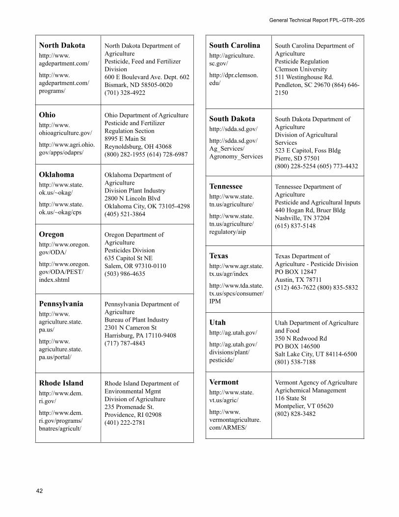
General Technical Report FPL–GTR–205
42
North Dakotahttp://www.agdepartment.com/
http://www.agdepartment.com/programs/
North Dakota Department of Agriculture Pesticide, Feed and Fertilizer Division 600 E Boulevard Ave. Dept. 602 Bismark, ND 58505-0020 (701) 328-4922
Ohiohttp://www.ohioagriculture.gov/
http://www.agri.ohio.gov/apps/odaprs/
Ohio Department of Agriculture Pesticide and Fertilizer Regulation Section 8995 E Main St Reynoldsburg, OH 43068 (800) 282-1955 (614) 728-6987
Oklahomahttp://www.state.ok.us/~okag/
http://www.state.ok.us/~okag/cps
Oklahoma Department of Agriculture Division Plant Industry 2800 N Lincoln Blvd Oklahoma City, OK 73105-4298 (405) 521-3864
Oregonhttp://www.oregon.gov/ODA/
http://www.oregon.gov/ODA/PEST/index.shtml
Oregon Department of Agriculture Pesticides Division 635 Capitol St NE Salem, OR 97310-0110 (503) 986-4635
Pennsylvaniahttp://www.agriculture.state.pa.us/
http://www.agriculture.state.pa.us/portal/
Pennsylvania Department of Agriculture Bureau of Plant Industry 2301 N Cameron St Harrisburg, PA 17110-9408 (717) 787-4843
Rhode Islandhttp://www.dem.ri.gov/
http://www.dem.ri.gov/programs/bnatres/agricult/
Rhode Island Department of Environmental Mgmt Division of Agriculture 235 Promenade St. Providence, RI 02908 (401) 222-2781
South Carolinahttp://agriculture.sc.gov/
http://dpr.clemson.edu/
South Carolina Department of Agriculture Pesticide Regulation Clemson University 511 Westinghouse Rd. Pendleton, SC 29670 (864) 646-2150
South Dakotahttp://sdda.sd.gov/
http://sdda.sd.gov/Ag_Services/Agronomy_Services
South Dakota Department of Agriculture Division of Agricultural Services 523 E Capitol, Foss Bldg Pierre, SD 57501 (800) 228-5254 (605) 773-4432
Tennesseehttp://www.state.tn.us/agriculture/
http://www.state.tn.us/agriculture/regulatory/aip
Tennessee Department of Agriculture Pesticide and Agricultural Inputs 440 Hogan Rd, Bruer Bldg Nashville, TN 37204 (615) 837-5148
Texashttp://www.agr.state.tx.us/agr/index
http://www.tda.state.tx.us/spcs/consumer/IPM
Texas Department of Agriculture - Pesticide Division PO BOX 12847 Austin, TX 78711 (512) 463-7622 (800) 835-5832
Utahhttp://ag.utah.gov/
http://ag.utah.gov/ divisions/plant/pesticide/
Utah Department of Agriculture and Food 350 N Redwood Rd PO BOX 146500 Salt Lake City, UT 84114-6500 (801) 538-7188
Vermonthttp://www.state.vt.us/agric/
http://www.vermontagriculture.com/ARMES/
Vermont Agency of Agriculture Agrichemical Management 116 State St Montpelier, VT 05620 (802) 828-3482
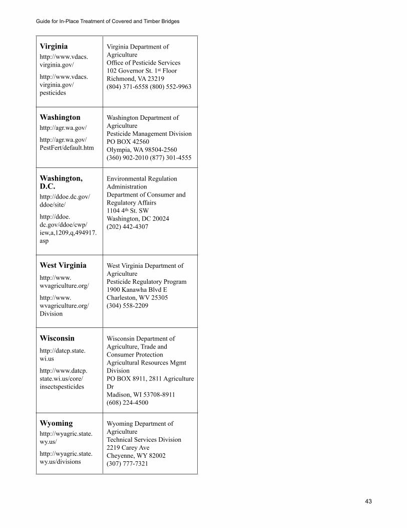
Guide for In-Place Treatment of Covered and Timber Bridges
43
Virginiahttp://www.vdacs.virginia.gov/
http://www.vdacs.virginia.gov/pesticides
Virginia Department of Agriculture Office of Pesticide Services 102 Governor St. 1st Floor Richmond, VA 23219 (804) 371-6558 (800) 552-9963
Washingtonhttp://agr.wa.gov/
http://agr.wa.gov/PestFert/default.htm
Washington Department of Agriculture Pesticide Management Division PO BOX 42560 Olympia, WA 98504-2560 (360) 902-2010 (877) 301-4555
Washington, D.C.http://ddoe.dc.gov/ddoe/site/
http://ddoe.dc.gov/ddoe/cwp/iew,a,1209,q,494917.asp
Environmental Regulation Administration Department of Consumer and Regulatory Affairs 1104 4th St. SW Washington, DC 20024 (202) 442-4307
West Virginiahttp://www.wvagriculture.org/
http://www.wvagriculture.org/Division
West Virginia Department of Agriculture Pesticide Regulatory Program 1900 Kanawha Blvd E Charleston, WV 25305 (304) 558-2209
Wisconsinhttp://datcp.state.wi.us
http://www.datcp.state.wi.us/core/insectspesticides
Wisconsin Department of Agriculture, Trade and Consumer Protection Agricultural Resources Mgmt Division PO BOX 8911, 2811 Agriculture Dr Madison, WI 53708-8911 (608) 224-4500
Wyominghttp://wyagric.state.wy.us/
http://wyagric.state.wy.us/divisions
Wyoming Department of Agriculture Technical Services Division 2219 Carey Ave Cheyenne, WY 82002 (307) 777-7321


