guardian - 广州市领驭电子科技有限公司ctnet.com.cn/pic/ingress_managr_3_manual.pdf ·...
TRANSCRIPT

���������������� ���
OPERATIONMANUAL
GUARDIAN
Ingress ManagRVersion 3.X
CommunicationsManager
Software for9580/9581
�����������

TRILITHIC, Inc. is a leading supplier of test equipment to the broadbandindustry, specializing in products and systems that make HFC systemmaintenance simpler, faster and more precise. Innovations include the firstpractical CATV sweep system (1976), the first CATV return adjustmentsystem (1981), the SEARCHER PLUS for leakage measurement (1989) andthe first integrated return path quality management system (1995).
TRILITHIC is very well known for its leakage products, and more than 15,000SEARCHER PLUS Leakage Receivers are now in daily use. The SUPERPLUS / CT-2 leak detection system carried leakage measurement into thecurrent era of overbuilds and digital services.
TRILITHIC has long been a leading supplier of signal level meters. Theground breaking TRICORDER, the first small, multifunction SLM with leakagemeasurement and data logging, has recently been joined by the Model One,which sets new standards for compactness, cost-effectiveness and function-ality.
TRILITHIC is a major force in return path quality assurance, offering theindustry’s only complete return maintenance system. The Guardian linespans the full range of return testing applications, and the Guardian RSVP,the first practical reverse path tester for installers, now equips many thou-sands of HFC installers around the world.
In addition to products for the broadband industry, TRILITHIC produces RFand microwave components and equipment that are integrated into theaerospace and wireless communications products of other manufacturers.TRILITHIC also designs custom test and measurement subsystems, supply-ing computer-controlled manufacturing, signal routing and network mainte-nance systems that perform a wide range of communications and aerospaceapplications.
TRILITHIC products are designed and manufactured at our facility in India-napolis, Indiana and in Tienjin, China, and are distributed by sales agents inover 40 countries. For more information concerning TRILITHIC products andservices, please contact us at the address or telephone numbers below orvisit our web site, www.trilithic.com.
TRILITHIC, Inc.9202 East 33rd. StreetIndianapolis, IN 46235(317) 895-3600(800) 344-2412
�����������

Ingress ManagR Windows Software – 1
�����������
General InformationIntroduction ..................................................................................... 5SNMP Compatitble ................................................................. 7Multiple Ingress Limits ........................................................... 7NCM-4 Support ....................................................................... 7FIFO File Limiting ................................................................... 8ArchiveR .......................................................................................... 8Multiple Ingress ManagR Copies .......................................... 9Customizable External Applications ...................................... 9Extended Frequency Coverage .............................................. 9Import Identification Files .......................................................10TraffiControl ..........................................................................10Simultaneous Modes .............................................................10Time Synchronization .............................................................10VieweR ............................................................................................ 11Communicating with your SST ..............................................11System Requirements ...........................................................11
Installation ProceduresInstall Software .......................................................................13Troubleshoot the Installation .................................................16Delete Ingress ManagR 3.X ...................................................16
Connecting PC and 9580/9581Introduction ..................................................................................... 17Cable Types ................................................................................... 17
Ingress ManagR WalkthroughIntroduction ..................................................................................... 21Menu Selection .......................................................................21On-Line Help .................................................................................. 21A Quick Tour ....................................................................................22
Main Menu Bar ................................................................22Status Bar ........................................................................23
Configure SoftwareIntroduction ..................................................................................... 25Connection Method ................................................................26
NCM-4 Setup ...................................................................27Direct Connection ...........................................................27
INDEX
Index
Tableof
Contents
�I
Ingress ManagR Windows Software2 –
�����������
Index
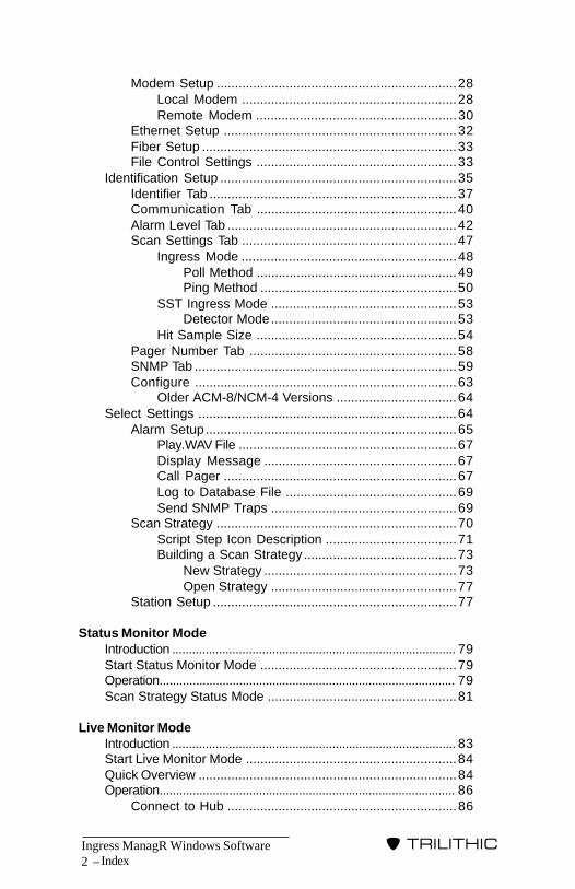
Modem Setup ..................................................................28Local Modem ...........................................................28Remote Modem .......................................................30
Ethernet Setup ................................................................32Fiber Setup ......................................................................33File Control Settings .......................................................33
Identification Setup .................................................................35Identifier Tab ....................................................................37Communication Tab .......................................................40Alarm Level Tab ...............................................................42Scan Settings Tab ...........................................................47
Ingress Mode ...........................................................48Poll Method .......................................................49Ping Method ......................................................50
SST Ingress Mode ...................................................53Detector Mode...................................................53
Hit Sample Size .......................................................54Pager Number Tab .........................................................58SNMP Tab ........................................................................59Configure ........................................................................63
Older ACM-8/NCM-4 Versions .................................64Select Settings .......................................................................64
Alarm Setup.....................................................................65Play.WAV File ............................................................67Display Message .....................................................67Call Pager ................................................................67Log to Database File ...............................................69Send SNMP Traps ...................................................69
Scan Strategy ..................................................................70Script Step Icon Description ....................................71Building a Scan Strategy..........................................73
New Strategy .....................................................73Open Strategy ...................................................77
Station Setup ...................................................................77
Status Monitor ModeIntroduction ..................................................................................... 79Start Status Monitor Mode ......................................................79Operation......................................................................................... 79Scan Strategy Status Mode ....................................................81
Live Monitor ModeIntroduction ..................................................................................... 83Start Live Monitor Mode ..........................................................84Quick Overview .......................................................................84Operation......................................................................................... 86
Connect to Hub ...............................................................86

Ingress ManagR Windows Software – 3
�����������
Hub Data Specifics ......................................................... 86Limit Threshold Setup (Apply) ........................................ 88Print Data ........................................................................ 89Save Command .............................................................. 89Message Display ............................................................ 90Disconnect the Hub ........................................................ 90
Playback ScreenIntroduction .................................................................................... 91Quick Overview ....................................................................... 91Operation......................................................................................... 92
Open File ......................................................................... 92Viewing Trace Data ......................................................... 93Playback Control ............................................................. 93Record Selection ............................................................ 94Print Playback Information .............................................. 95Sort Records ................................................................... 95
Change File Name .................................................. 95Save a Trace ................................................................... 96Close File ........................................................................ 96
Report ScreenIntroduction .................................................................................... 97Operation ....................................................................................... 98
ArchiveRIntroduction ..................................................................................... 99ArchiveR FIFO Management ..................................................101ArchiveR Overview ..................................................................101Basic Operation .....................................................................102Additional Operation Information ...........................................107
Edit Buttons .....................................................................107Log Tab ..........................................................................108Scheduler Boxes .............................................................108
VieweRIntroduction ..................................................................................... 109Setup ............................................................................................... 109Quick Overview .......................................................................111Operation ........................................................................................ 113
Connect to Hub ...............................................................113Hub Data Specifics .........................................................114Print Data ........................................................................115Message Display ............................................................116Disconnect the Hub ........................................................116
Additional Information ............................................................116Local Selection ...............................................................117External Selection ...........................................................117
Index

Ingress ManagR Windows Software4 –
�����������
Connection TemplatesIntroduction ..................................................................................... 119Using Nortons PC Anywhere .................................................120PC to SST(s) Remotely via Modems .....................................122PC to SST(s) Directly ..............................................................123PC to SST(s) Remotely via Dark Fiber ...................................124PC to PC to SST(s) Directly w/Modem ...................................125PC to PC to SST(s) Directly w/Pager .....................................126PC to PC to SST(s) Remotely ................................................127PC to PC to SST(s) Directly w/Network ..................................128PC to SST w/Two EI-1’s (Ethernet) ........................................129PC to SST w/NCM-4 (Ethernet) ..............................................130PC to SST w/EI-1 (Ethernet) ...................................................131
Sample FilesIntroduction ..................................................................................... 133Sample Scan Strategies ........................................................133
Sample1.SGY..................................................................134Sample2.SGY..................................................................135Sample3.SGY..................................................................137Sample4.SGY..................................................................138Sample5.SGY..................................................................140
Final Comment ......................................................................143
Miscellaneous InformationIntroduction .................................................................................... 145Connection Information .........................................................145
Modem DIP Switch Setting .............................................145Remote Modem .......................................................146Local Modem ...........................................................146
Ethernet Interface Information ........................................146Fiber Interface Information ..............................................147NCM-4 Interface Information ...........................................147
TCP/IP Setup............................................................148TCP/IP Installation Win ’98 ...............................148
Driver Information Boxes ........................................................149Event Log ........................................................................................ 150Time Synchronization .............................................................151
Index
Ingress ManagR Windows Software – 5
�����������
GENERALINFORMATION
General Information
IntroductionIngress ManagR for Windows is Trilithic’s powerful return pathstatus monitoring software which will give you access to the SSTand TPX devices in your 9580 SST or 9581 SST system via amodem, ethernet, dark fiber or direct connection to your PC.
This expanded version of Ingress ManagR has several excitingfeatures:
• SNMP compatible (see page 7)• Multiple Ingress Limits (see page 7)• Compatible with new NCM-4, version 3 (see page 7)• FIFO File Limiting (see page 8)• ArchiveR (see page 8)• Multiple Ingress ManagR Copies (see page 9)• Customizable External Applications (see page 9)• Extended Frequency Coverage up to 65 MHz (see page 9)• Ability to Import Older Identification Files (see page 10)• TraffiControl Mode (see page 10)• Auto Updating Status Display• Simultaneous Status Monitor/Live Monitor/Playback
Operation (see page 10)• Time Synchronization (see page 10)• VieweR (see page 11)
Ingress ManagR gives you instant access to your 9580 SST or9581 SST system from your office or main location. This meansthat if the SST is at a hub, you can access it from the PC at youroffice rather than having to drive out to a remote site. IngressManagR allows you to monitor sweep and ingress on any node inyour system as they occur via its LIVE MONITOR Mode.
Ingress ManagR’s flexibility enables you to perform a variety oftasks singly or simultaneously. You can watchdog every node inyour system or gather data from a single troublesome node bymonitoring ingress remotely up to 24 hours a day.
�1

Ingress ManagR Windows Software6 –
�����������
General Information
You gather and save SST data for specific times and nodesthroughout the day by building a SCAN STRATEGY and imple-menting it via the STATUS MONITOR Mode. These scripts builtby the SCAN STRATEGY acquire ingress data even when you arenot there monitoring events directly!
The NCM-4 provides for multiple user support. This means thatseveral users can run their SCAN STRATEGIES at the same time.Once you have the data, you can then develop databases forviewing and comparing the information. You can even link up withIngress ManagR at home or when you are travelling via the NCM-4Network Interface or by incorporating NORTON PC ANYWHEREremote computing software (by Symantec) into your system.
With this link up, if you get a pager call from Ingress ManagR at 5A.M., you won’t have to go all the way down to the office to seewhat triggered the alarm. Just dial up the PC running IngressManagR from your own PC to find out. If you are using the NCM-4with a network, you have even greater accessiblity to your system.For more information regarding this powerful feature of IngressManagR, see CONNECTION TEMPLATES on page 119.
In addition to monitoring and flagging problems as they occur,Ingress ManagR can notify you of such troubles either by loggingthe data to your PC or even calling you on your pager if you sodesignate through the ALARM setup feature. The alarm featureenables you to define several different alarm limits for analyzingingress data in your system. Ingress ManagR can alert you whenan ingress threshold is exceeded by:
• audio alarm (WAV.file)• display freq/amp message• call pager• log to disk for later review• send SNMP traps

Ingress ManagR Windows Software – 7
�����������
General Information
SNMP CompatibleIngress ManagR 3.X is compatible with SNMP (simple networkmanagement protocol). This is the standard protocol for transfer-ring information. It enables devices, even when manufactured bydifferent sources, to communicate in a common protocol. UsingSNMP, Ingress measurement data, device communication statusand other system information are stored in the SNMP MIB (man-agement information base) which is accessible to higher-levelmanagement applications through the open SNMP protocol.SNMP “traps” (alarms) can be configured to automatically notifyhigher management software of ingress events and equipment orcommunications failures. Traps can be set to notify multiplemanagement computers of several different types of problems (seeSNMP TAB, page 59).
Multiple Ingress LimitsIngress ManagR 3.X enables you to set multiple alarm limits pernode when you are configuring the software. See ALARM LEVELTAB, page 42).
NCM-4 SupportThe NCM-4 Network Interface can be used instead of the ACM-8and EI-1, depending on your system needs. This powerful inter-face performs as a server for four SSTs by buffering the returnspectra of up to 32 nodes. When used in the PING Mode (seepage 50), it can analyze return spectra INDEPENDENTLY whichminimizes LAN/Wan traffic and data processing time since itreports only those nodes which exceed ingress limits you haveset.
Since the NCM-4 functions as a network interface, multiple userscan access data from any SST in the system at the SAME time!The NCM-4 contains a protected hierarchial access for oneprimary or master user and up to nine secondary users (dependingon which version of the NCM-4 you are using).
Ingress ManagR Windows Software8 –
�����������
General Information
NOTE: NCM-4, version 3.X or higher supports six users withenhanced limit checking capabilities (one master, five secon-dary). For more information, refer to your NCM-4 OPERATIONMANUAL.
This enables you to make several functions exclusive to themaster user. The master user can set the DETECTOR Mode(Fast, Avg, etc.), configure Hubs, etc. Secondary users can runscan strategies or use LIVE Mode for viewing nodes. However,these secondary users cannot change the SST(s) configuration.
If you are using NCM-4, version 3.X or higher, in your hub, yoursystem will be able to accumulate MAX and MIN spectra for allmonitored nodes. It provides the MAX and MIN spectra, ping testresults and the latest “raw” spectra to multiple control sites so thatmore than one user can review the data.
You will need to install TCP/IP on your PC to utilize the NCM-4with some of Ingress ManagR’s features (see NCM-4 INTERFACEINFORMATION page 147).
FIFO File LimitingIngress ManagR supports FIFO (first in, first out) size limiting oflog files. When a file size reaches a user settable size (up to amaximum of 32,000), the oldest (10% to 50%) records are dis-carded to make room for the new records. Ingress MangeR’sdatabases use these same settings but the old data is archivedrather than discarded.
ArchiveRIngress ManagR’s ArchiveR is a software utility which enablesyou to store the data which accumulates in Ingress ManagR’sdatabase (.mdb) files permanently in a database. ArchiveRprovides a means for you to schedule regular storage events of asmany files as you desire at the times best suited to your systemneeds.

Ingress ManagR Windows Software – 9
�����������
Once ArchiveR has stored the data, it clears the files so that youno longer need to worry about overflowing it or losing importantdata. It also prevents storage of duplicate data. ArchiveR is fullynetwork compatible and is designed to run in the background onany computer running Ingress ManagR. ArchiveR can back up filesFROM the local drive TO any other drive in the network (seeARCHIVER, Chapter 10 on page 99, for more information).
CAUTION: If you are planning to use Ingress ManagR’sdatabase features to gather large amounts of ingress dataand alarms, we strongly recommend that you use ArchiveR.
Multiple Ingress ManagR CopiesIf you are using a network (NCM-4) connection, you may open aduplicate window of Ingress ManagR. This secondary window islimited in its features. One use is if you want to run a small ScanStrategy for diagnostic purposes offline from your main ScanStrategy. It is also useful if you wish to set up another small ScanStrategy to check a few new nodes while the main one is running.Although this secondary copy supports LIVE Mode, we recom-mend that you use VieweR (see page 109) if you wish to displayLIVE data outside of your primary Ingress ManagR.
Customizable External ApplicationsYou may use Ingress ManagR to automatically create an AC-CESS compatible database FIFO file for each ingress log file.This makes the ingress data available to any external applicationthat is ODBC (open database connectivity) compliant.
With this feature, you can customize external applications so thatyou can make your data analysis independent of Ingress ManagR.You can use ACCESS, EXCEL or other ODBC compliant softwareto generate analysis or reports.
Extended Frequency CoverageIngress ManagR supports the 9581 SST extended frequency of 65MHz. When using 65 MHz, all of the graphs in Ingress ManagRadjust to 65. Beginning with Ingress ManagR 3.0, databases havefields up to 65 MHz even if you are using 42 MHz units.
General Information
Ingress ManagR Windows Software10 –
�����������
General Information
Import Identification FilesIngress ManagR 3.X enables you to import identification files fromprevious versions of Ingress ManagR. This is useful for bringingexisting parameters into the upgraded software or for viewing oldPLAYBACK files (see MAIN MENU BAR page 22).
TraffiControlIngress MangeR now supports Trilithic’s TraffiControl Mode settingwhich enables you to measure and plot the ingress spectra ofbands occupied by return channels. TraffiControl automaticallyfilters all the data signals from the scanned return spectra so thatonly the ingress spectrum remains. By nature, digital channelsare intermittent or “bursty”. By utilizing TraffiControl Mode, youcan set a threshold so that you can view the ingress underneaththe signal. Ingress ManagR provides a way to capture theingress that would otherwise be hidden by taking advantage of theSST’s digital signal processing capability.
Simultaneous ModesIngress ManagR 3.x flexibility enables you to run multiple modesat the same time. For example, you may run Status Monitor, LiveMonitor and Playback all together.
NOTE: You may only run one operation of each modeconcurrently. This means that Ingress ManagR can runone Status Monitor, one Live Monitor and one Playbackoperation concurrently but cannot run two Status Monitorswith one Playback.
Time SynchronizationDepending on the configuration of your PC and the softwareprograms running within Windows, the Windows system clockmay lag behind the PC’s real time clock over a period of time.This can effect the correlation of data with date/time stamps. Youcan use Ingress ManagR’s Time Synchronization option (see page151) to eliminate this lag.

Ingress ManagR Windows Software – 11
�����������
General Information
VieweRIngress ManagR’s VieweR permits you to view sweep and ingressdata from your 9580/9581 as it occurs. This enables you to selectspecific Hub and Node information which you may wish to view.You can then print a trace as it happens. To utilize VieweR, youmay either import an existing Ingress ManagR Identification file orbuild a new one (see VieweR, page 109).
Communicating with Your SSTTrilithic has provided a Communications Manager option for your9580/9581 system. If your system is equipped with this option,you can connect up to eight SST’s (9580 SST) or up to four SSTs(9581 SST) to each ACM-8 circuit board. If you are using anNCM-4, you may connect up to four SSTs (9580 SST) or up to twoSSTs (9581 SST). Each Communications Manager is thenconnected to a PC via a modem, ethernet, dark fiber or directserial connection.
You can then connect each SST to as many as eight nodes (up tosixteen nodes when using the 9581). An ACM-8 contains addi-tional battery-backed RAM for ingress data monitoring andstorage.
System RequirementsIn order to run Ingress ManagR with all of its features, you need anIBM®-compatible computer with the following options:
• Pentium II or III, 500 MHz
• 64 Meg of RAM
• 50 Meg of Hard Drive space for installation
• 8 Gigabytes for Data Collection
• A Windows compatible mouse
• CD-ROM Drive
Ingress ManagR Windows Software12 –
�����������
General Information
• Color VGA Monitor with a resolution of 800 x 600 (or greater)and 256 Colors (or greater), using small or large font size(small font only with 800 x 600). The Windows Systemcolor map determines the color of the message boxes whichappear.
• Windows 98, Windows Millenium Edition, Windows NT 4(service pack 3 or higher), or Windows 2000 (recommended)
• COMM MANAGER (ACM-8, or NCM-4) option for the9580 SST or 9581 SST
• For NCM-4, EI-1 or SNMP support, Windows compatibleEthernet adapter with TCP/IP protocol installed
• For ACM-8, pager support, or direct connection, one or moreavailable COM ports (maximum 8)
• External 56K modem (ACM-8 or pager) or ethernetinterface or dark fiber interface for each ACM-8
• Programs needed to support ApplinkRMicrosoft Office ‘97Excel ‘97Access ‘97
Ingress ManagR is designed to work with the same setup you usefor Windows 98. If your Windows setup works smoothly, youshould have no difficulty running the software.
Ingress ManagR Windows Software – 13
�����������
INSTALLATIONPROCEDURES
Installation Procedures
Install SoftwareNow that you’ve checked the system requirements, you can installIngress ManagR. Ingress ManagR is designed for PCs withWindows 98, Windows Millenium Edition, Windows NT 4 (servicepack 3 or higher), or Windows 2000.
REMINDER: Depending on your PC’s configuration, you maynotice a time lag between the Window’s time display and thePC’s real time clock. Use Ingress ManagR’s TIMESYNCHRONIZATION option (see page 151) to eliminate thistime lag.
To install the software, use the following procedure:
1. Turn ON your PC and let Windows load.
2. Insert the disk into the CD-ROM drive. If autorun is enabled,Windows will detect and launch the Ingress ManagR setupwizard.
If autorun is not enabled, go to START, select RUN..., type inthe CD-ROM drive designation (i.e. d:), click BROWSE andlocate the file Setup.exe on the CD. You may also go toWindows Explorer and click on the Ingress ManagRSetup.exe file from the CD.
3. Windows displays a prompt indicating that you are about toinstall Ingress ManagR 3.X. Click OK to continue.
4. Depending on how your system is configured, it may benecessary to install additional Windows components. If suchcomponents are needed, click OK when the setup wizardprompts you. It may be necessary to reboot your PC duringthe components’ installation. If so, the setup wizard willcontinue automatically after the computer restarts.
� 2
Ingress ManagR Windows Software14 –
�����������
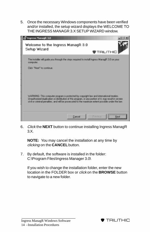
5. Once the necessary Windows components have been verifiedand/or installed, the setup wizard displays the WELCOME TOTHE INGRESS MANAGR 3.X SETUP WIZARD window.
6. Click the NEXT button to continue installing Ingress ManagR3.X.
NOTE: You may cancel the installation at any time byclicking on the CANCEL button.
7. By default, the software is installed in the folder:C:\Program Files\Ingress Manager 3.0\
If you wish to change the installation folder, enter the newlocation in the FOLDER box or click on the BROWSE buttonto navigate to a new folder.
Installation Procedures
Ingress ManagR Windows Software – 15
�����������
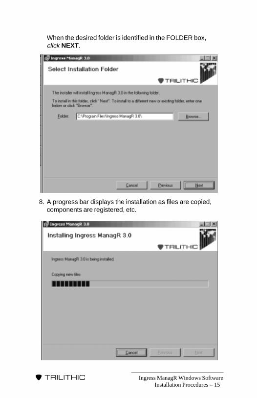
When the desired folder is identified in the FOLDER box,click NEXT.
8. A progress bar displays the installation as files are copied,components are registered, etc.
Installation Procedures
Ingress ManagR Windows Software16 –
�����������
Installation Procedures
9. Once the setup wizard is finished, it displays a popup windowthat indicates that Ingress ManagR 3.X was installed success-fully.
10. Click CLOSE to complete the installation.
NOTE: If you are prompted to reboot your computer, do sobefore you start Ingress ManagR 3.X to ensure that all of thecomponents finished installation.
11. When you are ready to use Ingress ManagR 3.X, go toSTART, click PROGRAMS and then select INGRESSMANAGR 3.X.
Troubleshoot the InstallationIf you have difficulties installing Ingress ManagR, you will need tocall Trilithic at (1-800-344-2412).
Delete Ingress ManagR 3.XIf you decide to delete the Ingress ManagR 3.X program, you canremove it as you do many other Windows applications.
Go to START, select SETTINGS and click on CONTROL PANEL.Select the ADD/REMOVE button (CHANGE/REMOVE in Windows2000 or the Windows Millenium edition). Select REMOVE IN-GRESS MANAGR 3.X.
NOTE: The Windows removal procedure only deletes theIngress ManagR 3.X program files, sample files and icon fromthe START menu icons. You will need to remove theconfiguration, strategy and database files in WindowsExplorer.
Ingress ManagR Windows Software – 17
�����������
CONNECTING PCAND 9580/9581
Let’s gettogether!
OK! How?
Connecting PC and 9580/9581
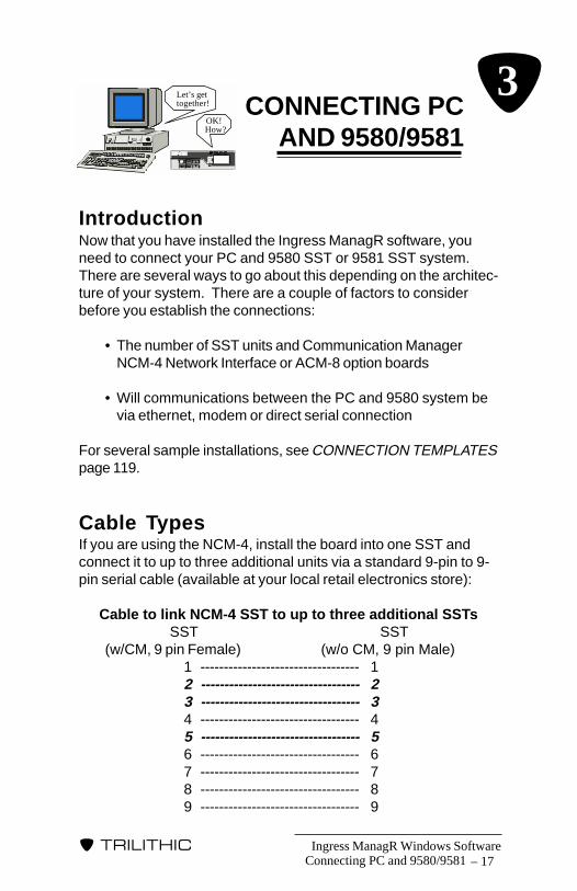
IntroductionNow that you have installed the Ingress ManagR software, youneed to connect your PC and 9580 SST or 9581 SST system.There are several ways to go about this depending on the architec-ture of your system. There are a couple of factors to considerbefore you establish the connections:
• The number of SST units and Communication ManagerNCM-4 Network Interface or ACM-8 option boards
• Will communications between the PC and 9580 system bevia ethernet, modem or direct serial connection
For several sample installations, see CONNECTION TEMPLATESpage 119.
Cable TypesIf you are using the NCM-4, install the board into one SST andconnect it to up to three additional units via a standard 9-pin to 9-pin serial cable (available at your local retail electronics store):
Cable to link NCM-4 SST to up to three additional SSTs SST SST(w/CM, 9 pin Female) (w/o CM, 9 pin Male)
1 ---------------------------------- 12 ---------------------------------- 23 ---------------------------------- 34 ---------------------------------- 45 ---------------------------------- 56 ---------------------------------- 67 ---------------------------------- 78 ---------------------------------- 89 ---------------------------------- 9
� 3

Ingress ManagR Windows Software18 –
�����������
The NCM-4 connects to the Ethernet via a shielded RJ45, cat-egory 5 cable.
Cable to link NCM-4 SST to Ethernet NCM-4 Ethernet
1 ---------------------------------- 1 white/orange2 ---------------------------------- 2 orange3 ---------------------------------- 3 white/green4 ---------------------------------- 4 blue5 ---------------------------------- 5 white/blue6 ---------------------------------- 6 green7 ---------------------------------- 7 white/brown8 ---------------------------------- 8 brown
NOTE: This cable must be shielded for CE compliance.
Cable to link ACM-8 SST to another SST SST SST(w/CM, 9 pin Female) (w/o CM, 9 pin Male)
1 ---------------------------------- 12 ---------------------------------- 23 ---------------------------------- 34 ---------------------------------- 45 ---------------------------------- 56 ---------------------------------- 67 ---------------------------------- 78 ---------------------------------- 89 ---------------------------------- 9
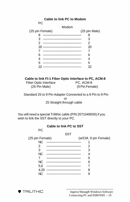
Cable to link Modem to SST Modem SST (25 pin Male) (w/CM, 9 pin Female)
8 --------------------------------------- 13 --------------------------------------- 22 --------------------------------------- 320 --------------------------------------- 47 --------------------------------------- 56 --------------------------------------- 64 --------------------------------------- 75 --------------------------------------- 822 --------------------------------------- 9
Connecting PC and 9580/9581
Ingress ManagR Windows Software – 19
�����������
Cable to link PC to Modem PC
Modem (25 pin Female) (25 pin Male)
8 --------------------------------------- 83 --------------------------------------- 32 --------------------------------------- 220 --------------------------------------- 207 --------------------------------------- 76 --------------------------------------- 64 --------------------------------------- 45 --------------------------------------- 522 --------------------------------------- 22
Cable to link FI-1 Fiber Optic Interface to PC, ACM-8 Fiber Optic Interface PC, ACM-8 (25 Pin Male) (9 Pin Female)
Standard 25 to 9 Pin Adapter Connected to a 9 Pin to 9 Pin or
25 Straight through cable
You will need a special Trilithic cable (P/N 2071049000) if youwish to link the SST directly to your PC.
Cable to link PC to SST PC
SST (25 pin Female) (w/CM, 9 pin Female)
NC ----------------------------------- 12 ----------------------------------- 23 ----------------------------------- 3NC ----------------------------------- 47 ----------------------------------- 5NC ----------------------------------- 65,6 ----------------------------------- 74,20 ----------------------------------- 8NC ----------------------------------- 9
Connecting PC and 9580/9581
Ingress ManagR Windows Software20 –
�����������
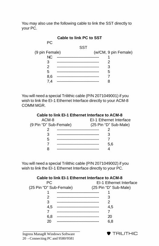
You may also use the following cable to link the SST directly toyour PC.
Cable to link PC to SST PC
SST (9 pin Female) (w/CM, 9 pin Female)
NC ----------------------------------- 13 ----------------------------------- 22 ----------------------------------- 35 ----------------------------------- 58,6 ----------------------------------- 77,4 ----------------------------------- 8
You will need a special Trilithic cable (P/N 2071049001) if youwish to link the EI-1 Ethernet Interface directly to your ACM-8COMM MGR.
Cable to link EI-1 Ethernet Interface to ACM-8 ACM-8 EI-1 Ethernet Interface (9 Pin “D” Sub-Female) (25 Pin “D” Sub-Male)
2 ----------------------------------- 23 ----------------------------------- 35 ----------------------------------- 77 ----------------------------------- 5,68 ----------------------------------- 4
You will need a special Trilithic cable (P/N 2071049002) if youwish to link the EI-1 Ethernet Interface directly to your PC.
Cable to link EI-1 Ethernet Interface to ACM-8 PC EI-1 Ethernet Interface(25 Pin “D” Sub-Female) (25 Pin “D” Sub-Male)
1 ----------------------------------- 12 ----------------------------------- 33 ----------------------------------- 24,5 ----------------------------------- 4,57 ----------------------------------- 76,8 ----------------------------------- 2020 ----------------------------------- 6,8
Connecting PC and 9580/9581
Ingress ManagR Windows Software – 21
�����������
INGRESSMANAGER
WALKTHROUGH
IntroductionBefore we proceed with setting up the parameters and usingIngress ManagR, you might want to take a minute or two tofamiliarize yourself with the software and how it works.
Menu SelectionThe easiest way to get around in Ingress ManagR is to use yourmouse to click on the desired menus just as you do in otherWindows Applications.
If you prefer, you may also use the keyboard to highlight themenus. PRESS the ALT tab key plus the letter for the desiredmenu. For example, to enter the FILE Menu, PRESS ALT and Fat the same time.
Once you are in a menu, you can use the arrow keys (←, ↑ , →, ↓ )to move within the menu. You can use the TAB key to scrollthrough choices in the various commands. Once a desiredcommand is highlighted, such as PLAYBACK in the MODE Menu,PRESS ENTER to select it.
On-Line HelpIngress ManagR is equipped with an on-line help function to assistyou in using the application. The basic help feature can beaccessed by selecting the HELP Menu.
Once you are inside the Help Menu System (Standard WindowsHelp), you can bring up other HELP screens by searching for keywords, referring to the HELP Menu’s Table of Contents, or bybringing up previously viewed Help Topics.
Ingress Manager Walkthrough
� 4
Ingress ManagR Windows Software22 –
�����������
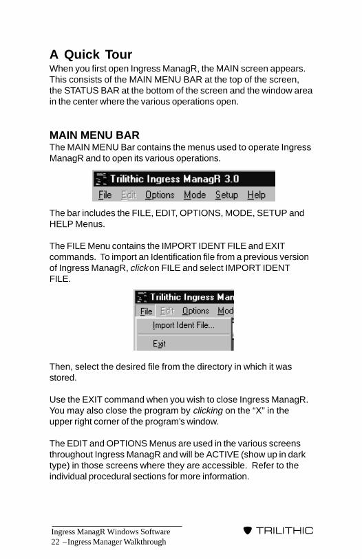
A Quick TourWhen you first open Ingress ManagR, the MAIN screen appears.This consists of the MAIN MENU BAR at the top of the screen,the STATUS BAR at the bottom of the screen and the window areain the center where the various operations open.
MAIN MENU BARThe MAIN MENU Bar contains the menus used to operate IngressManagR and to open its various operations.
The bar includes the FILE, EDIT, OPTIONS, MODE, SETUP andHELP Menus.
The FILE Menu contains the IMPORT IDENT FILE and EXITcommands. To import an Identification file from a previous versionof Ingress ManagR, click on FILE and select IMPORT IDENTFILE.
Then, select the desired file from the directory in which it wasstored.
Use the EXIT command when you wish to close Ingress ManagR.You may also close the program by clicking on the “X” in theupper right corner of the program’s window.
The EDIT and OPTIONS Menus are used in the various screensthroughout Ingress ManagR and will be ACTIVE (show up in darktype) in those screens where they are accessible. Refer to theindividual procedural sections for more information.
Ingress Manager Walkthrough

Ingress ManagR Windows Software – 23
�����������
The MODE Menu enables you to access the PLAYBACK com-mand which you can use to review records which were saved todisk. The REPORT command is located here as well. You alsoaccess the LIVE and STATUS MONITOR Modes which you use toobtain records via your communications link with the 9580 or 9581system.
Use the SETUP Menu to set the communications parameters andlinks such as the Baud Rate, Alarm Events, Identifiers, Modemsand Scan Strategies.
The HELP Menu is designed to help you locate informationregarding Ingress ManagR and its operations with a few clicks ofyour mouse.
STATUS BARThe STATUS BAR at the bottom of the MAIN screen displaysvarious operation messages and communication parameters. Ifyou are connecting via COM Ports, the boxes contain the param-eters as follows:
The Status Bar has fields across the bottom of the MAIN screen.These field are:
• Operator Message Field – Messages appearing in BLACKtext indicate normal operator information. Messages inRED text indicate an error. These RED text messages arealways accompanied by a beep. The messages appear inthe EVENT LOG (see page 150) and can be saved orarchived.
• Fields for COM Port connection (Live/Misc or Scanning):
1. Communications Field contains the Baud Rate, Parity,Data Bits and Stop Bits.
Ingress Manager Walkthrough
PC’s IP Address Port No. Remote IP Address
Operator Message
PC’s IP Address Port No. Remote IP Address
Operator Message
Ingress ManagR Windows Software24 –
�����������
Ingress Manager Walkthrough
2. Port Field contains the active communications port.
3. Handshaking Field displays the communication porthandshaking setting; HW (Hardware), NONE (None).
• Fields for Network connection (Live/Misc or Scanning):1. PC’s IP Address Field contains the IP Address used
by your PC.
2. Remote IP Address Field contains the IP Addressused by the remote device.
3. Port Number Field displays the communication portnumber.
Ingress ManagR Windows Software – 25
�����������
IntroductionOkay. You’ve got Ingress ManagR installed on your PC. Nowwhat? Before you use Ingress ManagR, you should give somethought to how you want to use it. A good place to start is bydetermining the system architecture you will be using.
REMINDER: Depending on your PC’s configuration, you maynotice a time lag between the Window’s time display and thePC’s real time clock. Use Ingress ManagR’s TIMESYNCHRONIZATION option (see page 151) to eliminate thistime lag.
At the core of your Guardian Return Maintenance system is the9580 SST or the 9581 SST. You can add multiple SST units toyour architecture and link them all together; maximizing theefficiency of your system. You can further extend the system’scapabilities by adding a Communications Manager (ACM-8, NCM-4) and/or the Test Point Expander (TPX) unit. For more informa-tion about the operation of the entire 9580/9581 system, refer tothe 9580 or 9581 RETURN ALIGNMENT SYSTEM operationmanual.
Once you have determined your system architecture, you willneed to establish your communications strategy or how IngressManagR and the various components of your system are tocommunicate. You set your communications strategy by configur-ing Ingress ManagR via the following:
• Connection Method (see page 26)• Identification Setup (see page 35)• Select Settings (see page 64)
NOTE: Once you have completed your connections andconfigured your setup, you can use LIVE MONITOR MODEto test the communications setup for each SST.
Configure Software
CONFIGURESOFTWARE
� 5
Ingress ManagR Windows Software26 –
�����������
Connection Method - Before Ingress ManagR can communicatewith the various components of your 9580/9581 system, you willneed to establish the connections. One of Ingress ManagR’sgreatest advantages is its versatility in this regard.
It enables you to communicate with your 9580 or 9581 system viaa direct communications link (PC to SST; PC to PC to SST),Ethernet or Fiber Optic link, modem or a combination of two ormore methods.
For example, you might wish to connect your headend SSTdirectly to the PC. Then, you might need to connect to satelliteSST units which are miles away via a network or a modem.
There is no “RIGHT” connection strategy. The single or combina-tion method you select will depend entirely on your system andperformance preferences. Refer to CONNECTION TEMPLATESpage 119 for some sample ideas.
Identification Setup - Once you have selected the connectionmethod, you need to set the identification parameters that IngressManagR will use for monitoring. These include: system identifica-tion information (such as hubs, SST units, nodes, several of yourtechnicians responsible for specific hubs may be connected viapagers, etc.); method of data gathering (poll, ping or a combinationof the two); and rate of data gathering (fast or normal).
Select Settings - When you have set up the identification param-eters, you need to select how you wish Ingress ManagR tomonitor such as: how you want the software to notify you ofpotential and/or real problems (alarms); and how your systemhubs will be monitored throughout the day (scan strategies).
Connection MethodBefore you start configuring Ingress ManagR, we recommend thatyou set up your hardware connections first.
Configure Software
Ingress ManagR Windows Software – 27
�����������
NCM-4 SETUPThe NCM-4 Ethernet Interface supports up to four SST units (up to32 nodes) or a TPX (up to 64 nodes) and can be set up as a multi-user network. This enables one primary or master user as well asup to nine secondary users to access data from any SST in thesystem. The NCM-4 performs the same functions as the ACM-8;including the PING Mode to decrease your access time (seePING METHOD page 50 for more information). Before youconnect the NCM-4 Ethernet Interface to your system, the unitmust have the IP Address set.
CAUTION: You cannot simply plug the NCM-4 Interface in.You must first ensure that each device in your network hasit’s own unique IP Address so that each component in yoursystem can communicate with the rest online in the network.
Once the IP Address is set, it is easy to install the NCM-4Network Interface. Connect the unit to up to three additional SSTsvia a standard 9-pin to 9-pin serial cable. Then, connect it to thenetwork via a standard RJ45, category 5 cable.
For more information regarding setting the IP Addresses andinstalling the unit, please refer to the NCM-4 ETHERNET INTER-FACE operation manual.
When the NCM-4 has been installed, set up the identificationparameters (see IDENTIFICATION SETUP page 35) and selectIngress ManagR’s settings (see SELECT SETTINGS page 64).
DIRECT CONNECTIONIngress ManagR can connect directly to a single SST or to anSST equipped with the Communications Manager (ACM-8) optionwhich enables the primary SST to manage up to seven satellite9580 SSTs or up to three 9581 SSTs.
NOTE: You must use a specific cable (P/N 2071049000) toconnect the PC Com Port to the SST (see page 19).
Once connected, proceed with setting up the identification param-eters (page 35) and selecting Ingress ManagR’s settings (page64).
Configure Software

Ingress ManagR Windows Software28 –
�����������
MODEM SETUPIf you selected MODEM as your Connection Method, you shouldset up the external REMOTE and LOCAL modems so that yourcommunications link will function properly. The LOCAL modemresides in or is connected to your PC while the REMOTE modemresides with the SST.
You may select one of our predefined modems (DEFAULT HayesCompatible, US Robotics Sportster,etc.) as well as edit thecommands directly. If you edit any modem string, the program willchange your modem type to USER. As new modem types areadded, Trilithic will post a new downloadable file (IM_MODEM.INI)to update your list of modems.
CAUTION: Before you use the setup procedure for amodem, review the operation and setup information whichcame with your modem. You do not have to be familiar withstandard modem commands to use this procedure but, if anycommand string changes are made, you should have yourmodem reference manual on hand.
To set up your modems, go to the SETUP Menu and select eitherLOCAL or REMOTE Modem.
Local ModemThe LOCAL MODEM screen consists of several areas.
REMINDER: You will need to set the COM Port where themodem is residing. See COMMUNICATION TAB on page40.
Configure Software
Ingress ManagR Windows Software – 29
�����������
Configure Software
The window on the left is used to set up the LOCAL modem DIALUP commands.
To the right is the window for designating the LOCAL modem’sHANG UP commands.
The DIAL UP and HANG UP commands default to the settingsused commonly by most modems. These settings include thecorrect hardware handshaking as well as the numeric responsecodes which your modem requires. The settings also instruct theLOCAL modem to use the fastest speed possible. If your modemrequires different settings, you can edit the default lines1 - 3 or add additional lines using the ADD (PLUS SIGN) and DEL(TRASH CAN) icons.
NOTE: The first three lines cannot be deleted. However,you can use the delete function or edit function to make anyof these lines a null operation by changing the text to simplyAT which is ignored by all modems.
For example:
To ADD a fourth line in the DIAL UP window, click on theADD button below that window and then double-click on theline you wish to add.

Ingress ManagR Windows Software30 –
�����������
To DELETE a line in the DIAL UP window, click on the lineyou wish to delete. You can only change lines one throughthree to AT. The DELETE command will remove lines fourand up. Then click on the TRASH CAN icon.
For further information, refer to the manual which came with yourmodem to verify the necessary settings.
On the lower right side of the screen is the area for selecting thetype of phone line in your system, either tone or pulsed. Mostlines are now tone lines although a few areas still use a pulsedline. Check with your phone company if you are not sure whichyou have.
Along the bottom of the screen is the window for selecting thetype of modem (default, US Robotics Sportster, etc.).
Once the LOCAL modem settings are correct, click on theCLOSE button.
NOTE: You may also need to set the DIP switches on themodem to optimize your communications. See MODEMDIP SWITCH SETTING on page 145.
Remote ModemBefore you connect the REMOTE modem into your 9580/9581system, you must first configure it using the PC so that it will usethe auto answer feature.
First, connect the modem to an available COM Port using thestandard serial cable which came with the modem.
Now, go to the SETUP Menu and select REMOTE modem.
Configure Software
Ingress ManagR Windows Software – 31
�����������
The left side of the window enables you to select the COM Port towhich the REMOTE Modem is connected for set up purposes.Click on the desired COM Port and a bullet appears in the circle.
At the top of the screen is the window for selecting the type ofmodem (default, US Robotics Sportster,etc.)
The box below the MODEM TYPE box contains the modemsettings. Ingress ManagR defaults to the most common REMOTEmodem settings which set up the modem for auto answering onthe first ring, 38.4kb/s serial communication and hardware hand-shaking.
CAUTION: You MUST make sure that your REMOTEModem has its serial port locked to 38.4kb/s. This can bedone via a software command in the setup string or you mayneed to set the DIP switches on the modem. See MODEMDIP SWITCH SETTING on page 145.
If your REMOTE modem requires different settings, select the linein the window and make your desired changes. Once you havefinished, click on the CONFIGURE REMOTE button.
Configure Software

Ingress ManagR Windows Software32 –
�����������
Configure Software
Once the settings are made, click on the CLOSE button. Youmay now proceed with setting up the identification parameters(see IDENTIFICATION SETUP page 35) and selecting IngressManagR’s settings (page 64).
ETHERNET SETUPThe EI-1 Ethernet Interface enables your 9580 or 9581 System tomake use of an existing network system which connects hubs,offices and headends. The advantage of using a network withIngress ManagR is that the time to access a hub is reduced toless than two seconds from the access time of a modem (oftenthirty seconds or more).
If you have the ACM-8 Communications Manager option installedin your SST, you can also use the PING Mode to decrease youraccess time even more. This can be very useful if you have alarge number of hubs in your system (see PING METHODpage 50 for more information).
Before you connect the EI-1 Ethernet Interface to your system, theunit(s) must have the IP Address set.
CAUTION: You cannot simply plug the EI-1 Ethernet Inter-face in. You must first ensure that each device in your net-work has it’s own unique IP Address so that each componentin your system can communicate with the rest online in thenetwork.
Once the IP Address is set, it is easy to install the EI-1 EthernetInterface. Connect the unit to an available COM Port on your PC(using Trilithic cable P/N 2071049002). Then connect the unit tothe SST’s COMM MGR’s (ACM-8) output (using Trilithic cable P/N2071049001).
For more information regarding setting the IP Addresses andinstalling the unit, please refer to the EI-1 ETHERNET INTER-FACE/FI-1 FIBER INTERFACE operation manual.
When the EI-1 has been installed, set up the identification param-eters (see IDENTIFICATION SETUP page 35) and select IngressManagR’s settings (page 64).
Ingress ManagR Windows Software – 33
�����������
FIBER SETUPThe FI-1 Fiber Interface enables your 9580 or 9581 System tomake use of any unused or “dark” fiber optic cables you mighthave in your system. This enables you to connect IngressManagR directly to any SSTs at remote hubs without needing touse a modem and the expense of additional phone lines.
Connect a HOST FI-1 Fiber Interface to your PC via a standardmodem to PC cable. Then, connect a REMOTE FI-1 FiberInterface to the primary SST’s COMM MGR’s (ACM-8) output.
The FI-1 Fiber Interface(s) need to be set to 38,400kb/s.
For more information regarding the installation procedure, pleaserefer to the EI-1 ETHERNET INTERFACE/FI-1 FIBER INTER-FACE operation manual.
When the FI-1 has been installed, set up the identificationparameters (see IDENTIFICATION SETUP page 35) and selectIngress ManagR’s settings (page 64).
File Control SettingsYou may also want to create an ACCESS compatible databaseFIFO file for each ingress log file. This enables you to analyzeingress data via ACCESS, EXCEL or the ApplinkR EXCEL macro,or other ODBC (open database connectivity) compliant softwareindependently of Ingress ManagR.
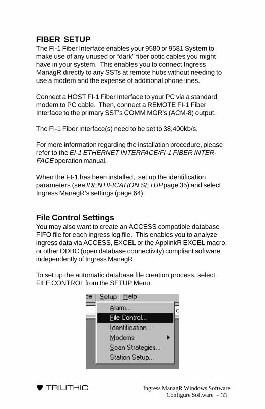
To set up the automatic database file creation process, selectFILE CONTROL from the SETUP Menu.
Configure Software
Ingress ManagR Windows Software34 –
�����������
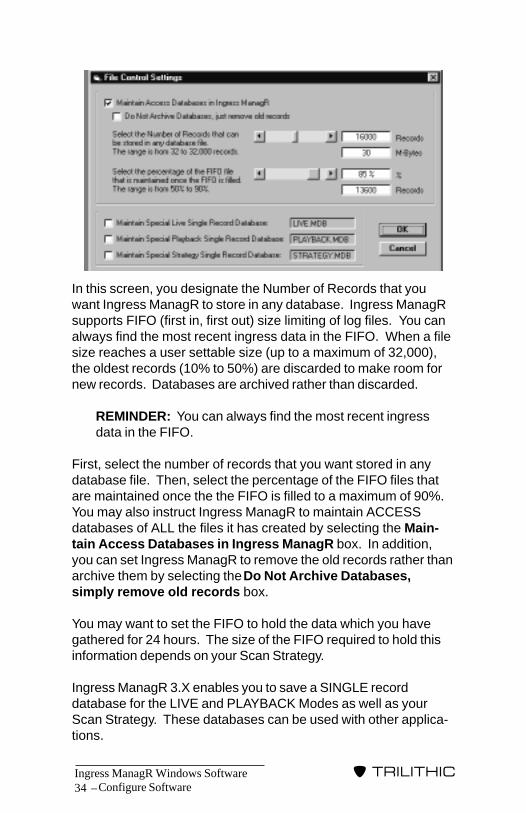
In this screen, you designate the Number of Records that youwant Ingress ManagR to store in any database. Ingress ManagRsupports FIFO (first in, first out) size limiting of log files. You canalways find the most recent ingress data in the FIFO. When a filesize reaches a user settable size (up to a maximum of 32,000),the oldest records (10% to 50%) are discarded to make room fornew records. Databases are archived rather than discarded.
REMINDER: You can always find the most recent ingressdata in the FIFO.
First, select the number of records that you want stored in anydatabase file. Then, select the percentage of the FIFO files thatare maintained once the the FIFO is filled to a maximum of 90%.You may also instruct Ingress ManagR to maintain ACCESSdatabases of ALL the files it has created by selecting the Main-tain Access Databases in Ingress ManagR box. In addition,you can set Ingress ManagR to remove the old records rather thanarchive them by selecting the Do Not Archive Databases,simply remove old records box.
You may want to set the FIFO to hold the data which you havegathered for 24 hours. The size of the FIFO required to hold thisinformation depends on your Scan Strategy.
Ingress ManagR 3.X enables you to save a SINGLE recorddatabase for the LIVE and PLAYBACK Modes as well as yourScan Strategy. These databases can be used with other applica-tions.
Configure Software

Ingress ManagR Windows Software – 35
�����������
If you wish to save a single database for LIVE Mode, select theMaintain Special Live Single Record Database box. To usethis function for records taken in PLAYBACK Mode, select theMaintain Special Playback Single Record Database“PLAYBACK.MDB”. You may also use this feature to comparethe different records of a single node taken by several strategiesby selecting the Maintain Special Strategy Single RecordDatabase “STRATEGY.MDB” box.
Once you have made the desired FILE CONTROL SETTINGselections, click on the CLOSE button.
Identification SetupOnce you have selected the connection method, you need to setthe identification parameters that Ingress ManagR will use formonitoring. These include: system identification information(such as hubs, SST units, nodes, etc.); SST detector settings forPOLL and PING Modes of data collection; rate of data gathering(fast or normal); alarm thresholds and SNMP traps. IngressManagR maintains records for Hubs, SSTs and Nodes by assign-ing a customized identification for each.
NOTE: Hub refers to where the SST is located. This mightbe a system “hub”, the headend or other site.
The set up also assigns a communication method to each Hub.All of the data is contained in a file called IDINFO.BIN. To makesure that you have common setup parameters amongst thecomputers in your system, just copy this file from computer tocomputer.
To set up the identification parameters, click on the SETUP Menuand then on IDENTIFICATION.
Configure Software

Ingress ManagR Windows Software36 –
�����������
Configure Software
This brings up the tabbed windows of the IDENTIFICATION Menuwhich include:
• Identifier, see IDENTIFIER TAB page 37 - creates/deletesID for hubs, SSTs, nodes
• Communication, see COMMUNICATON TAB page 40 -Sets the communication parameters (COM Port, BaudRate, Handshaking, Connection Method, etc.)
• Alarm Level, see ALARM LEVEL TAB page 42 - used to setthe Ingress threshold for each node.
• Scan Settings, see SCAN SETTINGS TAB page 47 - usedto assign the method by which Ingress ManagR requestsdata from Hubs.

Ingress ManagR Windows Software – 37
�����������
Configure Software
• Pager Number, see PAGER NUMBER TAB page 58 - usedto select the COM Port and phone number of the modemto which the Pager Alarm is to be issued.
• SNMP, see SNMP TAB page 59 - used to set up the trapsor alarms for the multiple management computers.
• Configure, see CONFIGURE page 63 - use to configure aHub which contains an ACM-8.
To access a specific window, just click on the desired tab. Onceyou have selected your information for each of the windows, clickon CLOSE to return to the MAIN screen.
IDENTIFIER TABUse the IDENTIFIER tab to create and/or delete the identificationfor a Hub or location where the 9580 SST or 9581 SST with theCOMM MGR option is located, each SST connected to thatCOMM MGR, and the Nodes connected to each SST.
When you first open Ingress ManagR, the IDENTIFIER tab will nothave any hubs listed.

Ingress ManagR Windows Software38 –
�����������
To create a Hub identifier, click on the PLUS icon.
Any time you add a Hub it will be listed as “UNUSED_HUB”.
Each hub has eight SSTs assigned to it and eight nodes assignedto each SST. You can either delete the Hub or rename andconfigure it for your own system.
NOTE: Deleted hubs are relabeled “UNUSED_HUB”.
If you wish Ingress ManagR to recognize a Hub, you must renamethe “UNUSED_HUB” files.
REMINDER: If you are using an NCM-4 with an SST, onlySSTs #1 – #4 are valid. If you are using an NCM-4 with aTPX, you may use all of the SSTs.
To rename a Hub, double click on the existing name (i.e. “UN-USED HUB”). This brings up the RENAME window.
Configure Software
Ingress ManagR Windows Software – 39
�����������
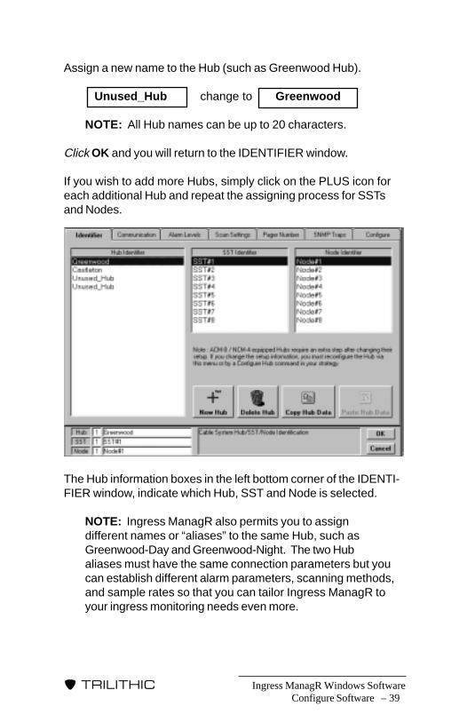
Assign a new name to the Hub (such as Greenwood Hub).
Unused_Hub change to Greenwood
NOTE: All Hub names can be up to 20 characters.
Click OK and you will return to the IDENTIFIER window.
If you wish to add more Hubs, simply click on the PLUS icon foreach additional Hub and repeat the assigning process for SSTsand Nodes.
The Hub information boxes in the left bottom corner of the IDENTI-FIER window, indicate which Hub, SST and Node is selected.
NOTE: Ingress ManagR also permits you to assigndifferent names or “aliases” to the same Hub, such asGreenwood-Day and Greenwood-Night. The two Hubaliases must have the same connection parameters but youcan establish different alarm parameters, scanning methods,and sample rates so that you can tailor Ingress ManagR toyour ingress monitoring needs even more.
Configure Software
Ingress ManagR Windows Software40 –
�����������
To delete Hub information, click on the name of the Hub you wishto delete and then click on the TRASH CAN/DELETE icon.
NOTE: Usually, you will not need to change any SST orNode identifiers. However, you may wish to change the SSTand Node designations to identifiers that you use in yoursystem. The main thing to remember is that the“UNUSED_HUB” designation needs to be changed to suityour own system. For example, if you are controlling fourSSTs with an NCM-4, you should rename SSTs #5 - #8 as“UNUSED” since they don’t exist in your system. If you areusing an NCM-4 with a TPX, you can support all eight.If you do need to change the SST and/or Node identifiers,double click on the desired SST or Node. A pop up windowwill appear. Type in the new designation.
You can NOT delete unused SSTs or Nodes. You shouldrename them as “UNUSED” since Ingress ManagR maygive errors if you try to access data for SSTs which aren’tthere.
For example, if you do not have an SST #2 in the GreenwoodHub, you should rename it as Unused.
NOTE: The terms UNUSED or INACTIVE are keywordsto Ingress ManagR. The program will not “poll” or“ping” an SST or Node which is designated UNUSED orINACTIVE.
Once you have finished updating the Hub, SST and Node informa-tion, you should continue your set up procedure by clicking one ofthe other tabs.
NOTE: If you were just editing an existing Hub and don’twish to make additional changes, click on the OK buttonto exit the IDENTIFIER screen.
COMMUNICATION TABCommunication parameters which need to be set up include: theCOM Port, Baud Rate, Handshaking, Connection Method, PhoneNumber or IP Address and 42 MHz or 65 MHz.
Configure Software

Ingress ManagR Windows Software – 41
�����������
NOTE: Due to Ingress ManagR’s flexibility, you can assigna different communication scheme to each Hub.
To select the communication parameters, click on the SETUPMenu and then on the IDENTIFICATION command line. Once theIDENTIFICATION Menu is available, select on the hub of interestand click on the COMMUNICATION tab.
NOTE: If you are using a modem or network interface, youmust assign a phone number or IP Address for each Hublisted in the IDENTIFIER tab. If you are using the NCM-4,you must also assign a Hub Password.
Select the desired COM Port (1 - 8).
NOTE: If you need to use communication ports 5 - 8, andare updating Ingress ManagR from an older version (Ver-sion 1 or earlier), you will need to modify the .ini file. UseWindows NOTEPAD to modify the INGMANGR.INI file in theWindows Directory so that: CMLINES=8
REMINDER: If your mouse is connected to COM Port 1, youneed to select a different COM Port for the communicationslink.
Next, select the desired Baud Rate.
NOTE: The default Baud Rate for the 9580 SST or9581 SST systems is 38,400 which is used for all types ofconnection. Use of the 19,200 Baud Rate may be neces-sary for certain equipment setups. Please contact Trilithicbefore you change to this setting.
Configure Software

Ingress ManagR Windows Software42 –
�����������
Configure Software
Then, choose the desired handshaking method. Usually, youshould use “HW”.
With version 1.40 or higher of Ingress ManagR, you can choose toconnect directly to your PC, via fiber optic interface FI-1, modemor network interface EI-1. Simply click on the desired CONNEC-TION METHOD.
In the example below, the user selected the DIRECT connect to aPC.
If you are using a MODEM, you must also enter a phone numberin the PHONE #/IP ADDRESS box.
NOTE: If you are using the EI-1 Ethernet Interface, you willneed to enter an IP address. See ETHERNET INTERFACEINFORMATION page 146.
You may test the communication set up by clicking the TESTbutton.
ALARM LEVEL TABOnce you have created a Hub, you should set the Ingress thresh-old for each Node as well as the number of times that thresholdcan be exceeded (hits). An alarm is triggered when the number ofhits reaches the limit within a specified number of samples (seeHIT SAMPLE SIZE page 54). This enables Ingress ManagR tomonitor the Hubs in the system and to notify you when ingressexceeds the desired levels.
Ingress ManagR enables you to set three offsets to the ingressalarm limit.

Ingress ManagR Windows Software – 43
�����������
To assign the level, click first on the desired Hub (i.e. Castleton).Then, click on the desired SST (i.e. SST #1) and Node (Node #1).All three items will be highlighted and will also appear in the Hubinformation boxes in the lower left corner of the IDENTIFICATIONwindow.
Click on the ALARM LEVEL tab to bring up the level screen forthe designated Hub, SST and Node.
The four limit thresholds are indicated by colored lines in the graphwhich correspond to the color of the limits’ labels. For example,Limit Four appears as a red line, Limit Three as orange, Limit Twoas yellow and Limit One as green. The LOW LIMIT appears asbrown while the Traffic Curve is blue. If a single ingress frequencydata point goes over the designated thresholds, Ingress ManagRconsiders that a hit.
You will assign the thresholds one at a time. To assign Limit Four,click on ALARM LIMIT FOUR.
Configure Software
Ingress ManagR Windows Software44 –
�����������
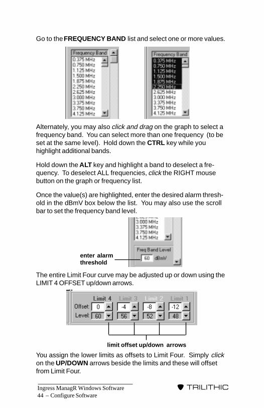
Go to the FREQUENCY BAND list and select one or more values.
Alternately, you may also click and drag on the graph to select afrequency band. You can select more than one frequency (to beset at the same level). Hold down the CTRL key while youhighlight additional bands.
Hold down the ALT key and highlight a band to deselect a fre-quency. To deselect ALL frequencies, click the RIGHT mousebutton on the graph or frequency list.
Once the value(s) are highlighted, enter the desired alarm thresh-old in the dBmV box below the list. You may also use the scrollbar to set the frequency band level.
The entire Limit Four curve may be adjusted up or down using theLIMIT 4 OFFSET up/down arrows.
You assign the lower limits as offsets to Limit Four. Simply clickon the UP/DOWN arrows beside the limits and these will offsetfrom Limit Four.
Configure Software
enter alarmthreshold
limit offset up/down arrows

Ingress ManagR Windows Software – 45
�����������
Configure Software
NOTE: The multiple alarm limit curve support in the GuardianReturn Path Alignment system requires that:
Limit 4 > = Limit 3 > = Limit 2 > = Limit 1
For this reason, Ingress ManagR will adjust the limit offsetsautomatically (in addition to the one you are adjusting directly)to enforce this requirement.
The LOW LIMIT appears as brown. At least one ingress frequencydata point must go over the designated thresholds or IngressManagR considers that the node is dead.
When the LOW LIMIT is set, all the frequencies are selectedautomatically. Set the Frequency Band Level by entering it in thedBmV window or via the scroll bar.
Traffic curve enables you to mask out the data signals and viewjust the ingress spectrum. The traffic curve is indicated by a seriesof medium and dark blue lines which extend from the top of thegraph to distinguish it from the limit curves.
NOTE: If you are using the TRAFFIC CURVE, you will needto select TRAFFIC for the DETECTOR Mode on the SCANSETTINGS TAB (see page 53).
NOTE: Use AVERAGING mode to establish the value.

Ingress ManagR Windows Software46 –
�����������
Configure Software
For example, the SST indicates that the average power of a datasignal is around 30dBmV between 2.250MHz and 4.125MHz.
To mask out the data signal, you need to set the traffic curvebelow 30dBmv (i.e. at 15dBmV).
Use the FREQUENCY BAND list (or click and drag on the graph)to select the values that will include 2.250MHz and 4.125MHz.Once the value(s) are highlighted, enter an alarm threshold value of15dBmV in the FREQUENCY BAND LEVEL box.
The ALARM LEVEL tab’s graph will indicate the selected trafficcurve in medium or dark blue. Adjacent traffic curve frequencybands alternate in color. This visually represents that they aremaintained separately even when they are set to the same level.
30dBmV
–20dBmV
2.250MHz 4.125MHz
30dBmV
–20dBmV
2.250MHz 4.125MHz
Traffic Curve at15dBmV

Ingress ManagR Windows Software – 47
�����������
Configure Software
If you would like to use similar limits for another Node, click on theCOPY NODE DATA button. Ingress ManagR memorizes thesettings. Now, pick another Node and click PASTE. This enablesyou to copy the settings from one Node to another quickly whenyou wish similar settings for each. You can then edit the limits onthe new Node for any minor differences. You may also copy thesettings to all of the Nodes on the selected Hub by clicking thePASTE ALL button.
NOTE: You may deactivate the alarm for a selected Nodeat any time by clicking on the Node and then on theDEACTIVATE THIS NODES ALARM box.
You also need to establish the number of times the selected Nodeneeds to reach its ingress threshold during a given sample groupto trigger an alarm. See HIT SAMPLE SIZE on page 54 for thisprocedure.
Once the Ingress threshold has been set for each Node, you mayreturn to the IDENTIFIER window to select the next SST at thatlocation or click CLOSE to exit the IDENTIFICATION Menu.
SCAN SETTINGS TABOnce you have created a Hub, you must assign the method bywhich Ingress ManagR requests data about the Nodes from theHub. The SCAN SETTINGS tab is where you set up how IngressManagR is to gather ingress data from each Node in a particularHub. Click on the SCAN SETTINGS tab.
Ingress ManagR Windows Software48 –
�����������
REMINDER: If you are using the NCM-4, only the MASTERor primary user can assign the Scan Settings. The secon-dary users’ settings will be ignored by the NCM-4.
In this tab, you assign the desired Ingress Mode. This is whereyou decide:
1. The type of Ingress Mode that you will use (see INGRESSMODE below).
A. POLL Method - Ingress ManagR requests the ACM-8 orNCM-4 to gather data for each Node (see POLL METHODpage 49).
B. PING Method - The ACM-8 or NCM-4 gathers ingress dataand stores it until Ingress ManagR asks or “pings” theACM-8 or NCM-4 for it (see PING METHOD page 50).
REMINDER: Your SST MUST have the ACM-8 COMMMGR option or the NCM-4 to use the PING Method.
2. The rate Ingress ManagR collects data within each timingframe (approximately 725 milliseconds for the 9580; 800milliseconds for the 9581): NORMAL or FAST. For moreinformation, see SST INGRESS MODE page 53.
NOTE: If using FAST, you will also need to select theDETECTOR Mode: Peak, Average or Traffic (see page 53).
3. The number of times that Ingress ManagR looks at a Node tosee if it has reached its hit limit (see HIT SAMPLE SIZE page54).
Ingress ModeOne thing to remember is that you are not “locked” into a specificscanning method, scanning rate or even sample rate for a givenNode. With the flexibility of Ingress ManagR’s scanning strate-gies, you can set up different Ingress Modes, SST Mode rates andHub Samples for Resets for the same Node throughout the courseof a day to suit your system needs as they change. By assigningdifferent names or “aliases” to the same Hub, you can set up yourscan strategy to include different limits or detector modes.
Configure Software
Ingress ManagR Windows Software – 49
�����������
NOTE: If you are using the NCM-4, the Master user needsto set the Ingress Modes based on an agreed schedule withthe secondary users so that all users can use IngressManageR optimally.
For example, you can set up a Hub with a different name for dayand night scanning. One possibility is to set up Ingress ManagRso that it will alternate POLL and PING with the SST in NORMALMode. This enables you to collect your ingress data and stillpermits your techs to sweep. Then, at night, you can switch toPOLL and PING in FAST Mode. For more information on this typeof set up, see SCAN STRATEGY on page 70 and theSAMPLE3.SGY on page 137.
The main thing to keep in mind is that the POLL and PINGMethods each have certain advantages. The POLL Methodenables you to collect and save a more detailed overview of whatyour system is doing. Also, it is slower than the PING Method sothat you can determine the persistence of an ingress problem.The PING Method enables Ingress ManagR to streamline yourdata gathering by pinging one Communication Manager right afteranother. This is the fastest way to get around your system.However, the PING Method only allows you to gather “bad” data.That is, it only stores ingress that has exceeded threshold andtriggered an alarm.
POLL METHODWhen Ingress ManagR polls, it basically asks the COMM MGR togather data for each Node which the PC then compares to thedesired threshold limits versus frequency for that node.
The POLL settings control how Ingress ManagR collects datawhen polling an SST. In your Scan Strategy, SCAN HUB or SCAN1 HUB utilizes the “poll” settings. These scan strategy stepsactually retrieve live real time data from the Hub at the time thestep is executed.
NOTE: The POLL Method can be used with either theACM-8 or NCM-4 Communications Manager.
Configure Software

Ingress ManagR Windows Software50 –
�����������
To select either FAST or NORMAL Ingress Mode, click on thedesired setting (see SST INGRESS MODE page 53 for moreinformation). A bullet appears in the circle next to the mode.
NOTE: FAST Mode disables field sweeping.
WARNING!!!!!Polling an ACM-8 DISABLES it’s automatic data collectionmode. You MUST check the RETURN ACM TO SCAN box ifyou want the ACM-8 to return to pinging after polling has beencompleted. Otherwise, the ACM-8 will miss the first ping aftera poll so that you may miss ingress.
Finally, set the POLL HIT SAMPLE SIZE (see HIT SAMPLE SIZEpage 54).
PING METHODWhen using the PING Method, the data collection and comparisonto limits process occurs in the ACM-8 or NCM-4 rather than inIngress ManagR itself. By allowing the ACM-8 or NCM-4 to do thework, each node can be checked in seconds (twelve seconds foreight SSTs; twelve seconds for a TPX with sixty four test points)as opposed to the minutes or even hours that it can take to POLLa system with a large number of Hubs.
Configure Software
Ingress ManagR Windows Software – 51
�����������
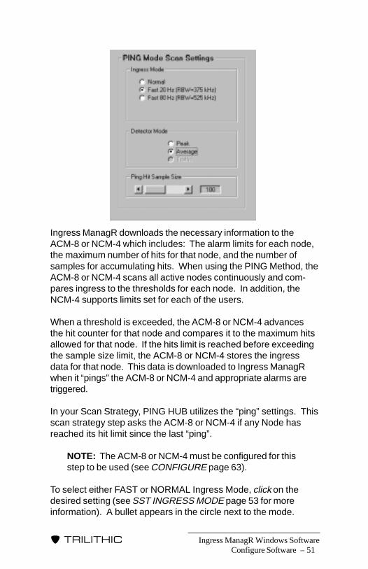
Ingress ManagR downloads the necessary information to theACM-8 or NCM-4 which includes: The alarm limits for each node,the maximum number of hits for that node, and the number ofsamples for accumulating hits. When using the PING Method, theACM-8 or NCM-4 scans all active nodes continuously and com-pares ingress to the thresholds for each node. In addition, theNCM-4 supports limits set for each of the users.
When a threshold is exceeded, the ACM-8 or NCM-4 advancesthe hit counter for that node and compares it to the maximum hitsallowed for that node. If the hits limit is reached before exceedingthe sample size limit, the ACM-8 or NCM-4 stores the ingressdata for that node. This data is downloaded to Ingress ManagRwhen it “pings” the ACM-8 or NCM-4 and appropriate alarms aretriggered.
In your Scan Strategy, PING HUB utilizes the “ping” settings. Thisscan strategy step asks the ACM-8 or NCM-4 if any Node hasreached its hit limit since the last “ping”.
NOTE: The ACM-8 or NCM-4 must be configured for thisstep to be used (see CONFIGURE page 63).
To select either FAST or NORMAL Ingress Mode, click on thedesired setting (see SST INGRESS MODE page 53 for moreinformation). A bullet appears in the circle next to the mode.
Configure Software
Ingress ManagR Windows Software52 –
�����������
NOTE: FAST Mode disables field sweeping.
If you choose to operate in FAST Mode, you also need to selectPEAK, AVERAGE or TRAFFIC Detector Mode (see DETECTORMODE page 53).
Finally, set the PING HIT SAMPLE SIZE (see HIT SAMPLE SIZEpage 54).
The ACM-8 or NCM-4 works faster because it stores the thresholdfor each Node as well as the hits counters. It only looks at theNodes which are connected so it can PING up to sixty four Nodeswithin a few seconds if connected directly.
NOTE: The time it takes to go through one group of Hubsamples depends on the connection method. If you areusing a modem, for example, it may take longer due to thetime needed to connect.
When a threshold is exceeded, the ACM-8 or NCM-4 advancesthe hit counter for that Node and compares it to the maximum hitsallowed for it. If the hits limit is reached, the ACM-8 or NCM-4stores the ingress data for that Node and goes on to the nextconnected Node. For more information about hits limits andincrementing the counter, see HIT SAMPLE SIZE page 54.
When set to the PING Method, Ingress ManagR PINGs the ACM-8 or NCM-4. It checks the alarm flag to see if the ACM-8 or NCM-4 has noted any alarms since the last PING. If there are noalarms, Ingress ManagR proceeds directly to the next HUB. Ifthere are alarms, Ingress ManagR downloads the ingress spec-trum data for each “out of limits” Node and processes the alarmsbefore PINGING the next Hub.
Since the PING Method is so fast compared to the POLL Method,you may want to set the Hub sample size to a higher number (i.e.100) and then select the desired percentage of “hits” to 20% or30% (i.e. 20 or 30). Otherwise, you could be “bombarded” byshort duration ingress events.
Configure Software
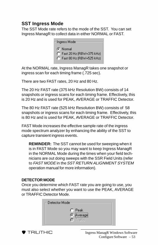
Ingress ManagR Windows Software – 53
�����������
SST Ingress ModeThe SST Mode rate refers to the mode of the SST. You can setIngress ManagR to collect data in either NORMAL or FAST.
At the NORMAL rate, Ingress ManagR takes one snapshot oringress scan for each timing frame (.725 sec).
There are two FAST rates, 20 Hz and 80 Hz.
The 20 Hz FAST rate (375 kHz Resolution BW) consists of 14snapshots or ingress scans for each timing frame. Effectively, thisis 20 Hz and is used for PEAK, AVERAGE or TRAFFIC Detector.
The 80 Hz FAST rate (525 kHz Resolution BW) consists of 58snapshots or ingress scans for each timing frame. Effectively, thisis 80 Hz and is used for PEAK, AVERAGE or TRAFFIC Detector.
FAST Mode increases the effective sample rate of the ingressmode spectrum analyzer by enhancing the ability of the SST tocapture transient ingress events.
REMINDER: The SST cannot be used for sweeping when itis in FAST Mode so you may want to keep Ingress ManagRin the NORMAL Mode during the times when your field tech-nicians are out doing sweeps with the SSR Field Units (referto FAST MODE in the SST RETURN ALIGNMENT SYSTEMoperation manual for more information).
DETECTOR MODEOnce you determine which FAST rate you are going to use, youmust also select whether you want to use the PEAK, AVERAGEor TRAFFIC Detector Mode.
Configure Software

Ingress ManagR Windows Software54 –
�����������
Configure Software
Use the PEAK detection scheme to enable the SST to capturetransient ingress events.
The AVERAGE detection scheme is used to reduce the noise floordisplayed on the SST when measuring CW or common path.
NOTE: The AVERAGE detection scheme is an option. Ifyour SST is not equipped with it, Ingress ManagR willsimply ignore the AVERAGE selection and default to thePEAK detector scheme. (See DETECTOR in the SSTRETURN ALIGNMENT SYSTEM operation manual.)
The TRAFFIC setting suppports Trilithic’s TraffiControl option andenables you to measure ingress in active digital channels. Bytaking advantage of the “bursty” nature of digital channels, IngressManagR enables you to capture ingress that would be hiddenotherwise. When the digital channel is ON, the TraffiControlenabled SST does nothing. When the channel is OFF, the SSTpeak holds the sample to show the ingress within the channel.Signals above the TraffiControl setting are disposed of whileingress below the setting is kept for further review or archiving.
NOTE: The TRAFFIC detection scheme is an option. Ifyour SST is not equipped with it, Ingress ManagR willsimply ignore the TRAFFIC selection and default to thePEAK detector scheme. (See DETECTOR in the SSTRETURN ALIGNMENT SYSTEM operation manual.)
Hit Sample SizeWhether you are POLLING or PINGING, you need to establish thenumber of times each Node in a particular Hub is queried orinspected to determine whether its hits limit has been reached.You also need to determine the number of threshhold breaks (hits)the Node must have to trigger an alarm event in a given set of hitsamples.

Ingress ManagR Windows Software – 55
�����������
You set this data by assigning the value for the POLL HITSAMPLE SIZE or PING HIT SAMPLE SIZE in conjunction with theHITS BEFORE ALARM value (which is located on the ALARMLEVEL Tab, see page 42).
The hit sample size refers to the number of times a Node isqueried or inspected within a sample set. For example, if youassign the number “10” in the HIT SAMPLE SIZE, the Node isqueried ten times to form a sample set. On the eleventh pass, theNode hit counters are reset to zero and this pass forms passnumber “1” in the next sample set.
NOTE: Whatever value you assign to the hit sample size isuniversal for a Hub. That means that all connected Nodes ofthat Hub will be queried the same number of times.
As the ACM-8 or NCM-4 queries the hit sample set, it comparesthe number of threshold breaks it finds at a Node with the numberof threshold breaks needed to trigger an alarm event. This numberis set on the POLL HITS TO ALARM and the PING HITS TOALARM bars on the ALARM LEVEL Tab. For example, you maydecide that you want to be notified via an alarm event if a Nodereaches threshold break thirty percent of the time. If you arePOLLING, you could assign a value of “3/10 (30%)” on the POLLHITS BEFORE ALARM. This means that the Node has to reachit’s threshold break three times out of ten queries within the hitsample set to trigger the alarm.
Configure Software
Scan Setting Tab + Alarm Levels Tab

Ingress ManagR Windows Software56 –
�����������
When the threshold breaks trigger an alarm event, the ingress flaggoes true for the next poll and the ingress data is uploaded intoIngress ManagR.
Finally, keep in mind that Ingress ManagR resets the number ofthreshold breaks in several ways:
• When Ingress ManagR starts up, it sets the thresholdbreak counters to zero for ALL Nodes of ALL Hubs.
• When the number assigned for the Hit Sample Size hasbeen reached (Nodes have been polled or pinged thenumber of passes in a hit sample set), Ingress ManagRsets the threshold break counters to zero for ALL Nodes ofa specific Hub.
• After an alarm is triggered for a particular Node, IngressManageR sets the threshold break counter to zero for thatspecific Node.
For example, let’s say that you want Ingress ManagR to poll (seePOLL METHOD on page 49 for more detailed information onpolling) a Hub that has four Nodes. The first two Nodes are solidperformers that rarely have ingress. The third Node is always aproblem while the fourth Node is just so-so. You decide that it ismost efficient to let Ingress ManagR gather it’s data in hit samplesets of ten passes. So, set the POLL HIT SAMPLE SIZE bar to“10”.
This means, that Ingress ManagR will poll ALL the Nodes tenconsecutive times (one hit sample set) and accumulate thenumber of hits (times the Nodes reach threshold break). If anyNode reaches its limit (hits before alarm) during a particularsample set, the alarm for that Node is triggered or activated andit’s hit counter is reset to zero. Once the tenth poll in the sampleset is completed, Ingress ManagR resets the hits counters for ALLof the Nodes in that Hub and starts the next hit sample set.
Configure Software

Ingress ManagR Windows Software – 57
�����������
Configure Software
REMINDER: You set the number of “hits” (times a Nodemust exceed threshold within EACH sample set of ten beforean alarm is triggered) on the set up for the Node (seeALARM LEVEL TAB page 42).
In this example, the POLL HITS TO ALARM counter is set to “3”or three hits to 10 polls (3/10) which means that thirty percent ofthe queries for a sample set must reach threshold break to triggeran alarm event.
Okay. Ingress ManagR starts polling.
1. On query 1, Node 3 reaches it’s threshold break.
2. On query 2, Node 1 and Node 4 reach threshold. Note thatwhile there have been THREE “hits”, there are no alarms sinceno single Node has reached threshold three times.
3. Queries 3, 4 and 5 are clean.
4. On query 6, Node 3 and Node 2 reach threshold.
5. On query 7, Node 3 reaches threshold. This event triggers analarm since the Node has reached threshold break threetimes, the limit you set for the POLL HITS TO ALARM counter(3/10). At this point, Node 3’s threshold break counter is resetto zero. However, since only seven queries have been com-pleted, Ingress ManagR continues to poll.
6. Queries 8 and 9 are clean.
7. On query 10, Node 4 reaches threshold. Since it has onlyreached threshold twice, it does not trigger an alarm. At thistime, the number of queries for a complete hit sample set (10)has been reached so the threshold break counters are reset tozero for ALL of the Nodes in that Hub.
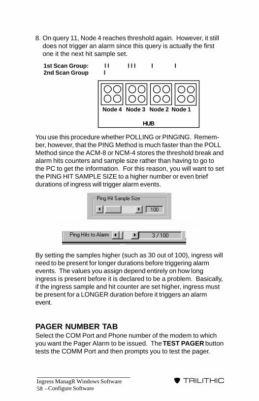
Ingress ManagR Windows Software58 –
�����������
Configure Software
8. On query 11, Node 4 reaches threshold again. However, it stilldoes not trigger an alarm since this query is actually the firstone it the next hit sample set.
You use this procedure whether POLLING or PINGING. Remem-ber, however, that the PING Method is much faster than the POLLMethod since the ACM-8 or NCM-4 stores the threshold break andalarm hits counters and sample size rather than having to go tothe PC to get the information. For this reason, you will want to setthe PING HIT SAMPLE SIZE to a higher number or even briefdurations of ingress will trigger alarm events.
By setting the samples higher (such as 30 out of 100), ingress willneed to be present for longer durations before triggering alarmevents. The values you assign depend entirely on how longingress is present before it is declared to be a problem. Basically,if the ingress sample and hit counter are set higher, ingress mustbe present for a LONGER duration before it triggers an alarmevent.
PAGER NUMBER TABSelect the COM Port and Phone number of the modem to whichyou want the Pager Alarm to be issued. The TEST PAGER buttontests the COMM Port and then prompts you to test the pager.
HUB
Node 4 Node 3 Node 2 Node 1
1st Scan Group: l l l l l l l2nd Scan Group l
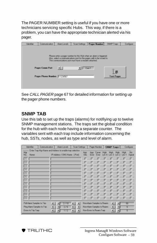
Ingress ManagR Windows Software – 59
�����������
The PAGER NUMBER setting is useful if you have one or moretechnicians servicing specific Hubs. This way, if there is aproblem, you can have the appropriate technician alerted via hispager.
See CALL PAGER page 67 for detailed information for setting upthe pager phone numbers.
SNMP TABUse this tab to set up the traps (alarms) for notifiying up to twelveSNMP management stations. The traps set the global conditionfor the hub with each node having a separate counter. Thevariables sent with each trap include information concerning thehub, SSTs, nodes, as well as type and level of alarm.
Configure Software
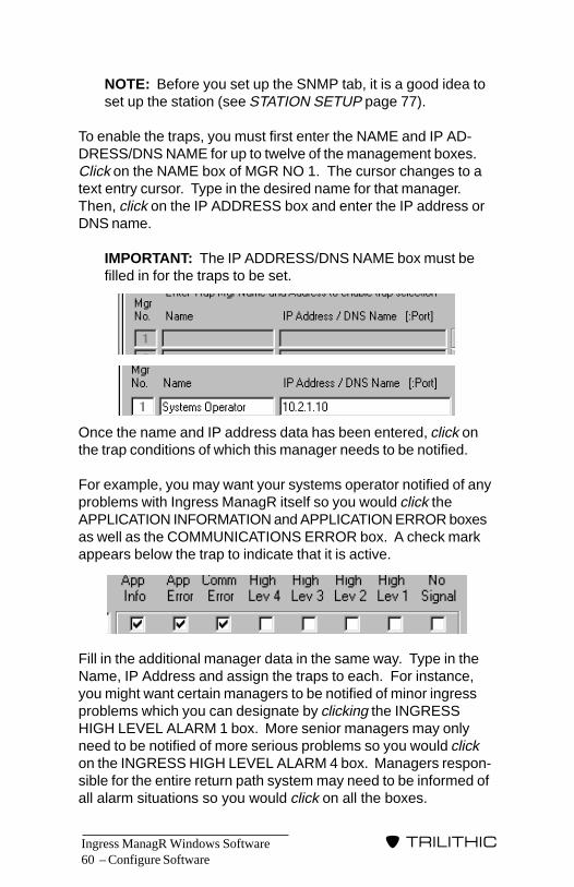
Ingress ManagR Windows Software60 –
�����������
Configure Software
NOTE: Before you set up the SNMP tab, it is a good idea toset up the station (see STATION SETUP page 77).
To enable the traps, you must first enter the NAME and IP AD-DRESS/DNS NAME for up to twelve of the management boxes.Click on the NAME box of MGR NO 1. The cursor changes to atext entry cursor. Type in the desired name for that manager.Then, click on the IP ADDRESS box and enter the IP address orDNS name.
IMPORTANT: The IP ADDRESS/DNS NAME box must befilled in for the traps to be set.
Once the name and IP address data has been entered, click onthe trap conditions of which this manager needs to be notified.
For example, you may want your systems operator notified of anyproblems with Ingress ManagR itself so you would click theAPPLICATION INFORMATION and APPLICATION ERROR boxesas well as the COMMUNICATIONS ERROR box. A check markappears below the trap to indicate that it is active.
Fill in the additional manager data in the same way. Type in theName, IP Address and assign the traps to each. For instance,you might want certain managers to be notified of minor ingressproblems which you can designate by clicking the INGRESSHIGH LEVEL ALARM 1 box. More senior managers may onlyneed to be notified of more serious problems so you would clickon the INGRESS HIGH LEVEL ALARM 4 box. Managers respon-sible for the entire return path system may need to be informed ofall alarm situations so you would click on all the boxes.
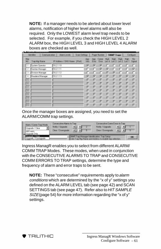
Ingress ManagR Windows Software – 61
�����������
Configure Software
NOTE: If a manager needs to be alerted about lower levelalarms, notification of higher level alarms will also berequired. Only the LOWEST alarm level trap needs to beselected. For example, if you check the HIGH LEVEL 2ALARM box, the HIGH LEVEL 3 and HIGH LEVEL 4 ALARMboxes are checked as well.
Once the manager boxes are assigned, you need to set theALARM/COMM trap settings.
Ingress ManagR enables you to select from different ALARM/COMM TRAP Modes. These modes, when used in conjunctionwith the CONSECUTIVE ALARMS TO TRAP and CONSECUTIVECOMM ERRORS TO TRAP settings, determine the type andfrequency of alarm and error traps to be sent.
NOTE: These “consecutive” requirements apply to alarmconditions which are determined by the “x of y” settings youdefined on the ALARM LEVEL tab (see page 42) and SCANSETTINGS tab (see page 47). Refer also to HIT SAMPLESIZE (page 54) for more information regarding the “x of y”settings.
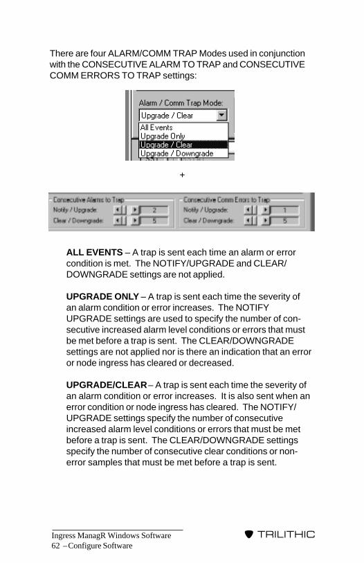
Ingress ManagR Windows Software62 –
�����������
There are four ALARM/COMM TRAP Modes used in conjunctionwith the CONSECUTIVE ALARM TO TRAP and CONSECUTIVECOMM ERRORS TO TRAP settings:
+
ALL EVENTS – A trap is sent each time an alarm or errorcondition is met. The NOTIFY/UPGRADE and CLEAR/DOWNGRADE settings are not applied.
UPGRADE ONLY – A trap is sent each time the severity ofan alarm condition or error increases. The NOTIFYUPGRADE settings are used to specify the number of con-secutive increased alarm level conditions or errors that mustbe met before a trap is sent. The CLEAR/DOWNGRADEsettings are not applied nor is there an indication that an erroror node ingress has cleared or decreased.
UPGRADE/CLEAR – A trap is sent each time the severity ofan alarm condition or error increases. It is also sent when anerror condition or node ingress has cleared. The NOTIFY/UPGRADE settings specify the number of consecutiveincreased alarm level conditions or errors that must be metbefore a trap is sent. The CLEAR/DOWNGRADE settingsspecify the number of consecutive clear conditions or non-error samples that must be met before a trap is sent.
Configure Software

Ingress ManagR Windows Software – 63
�����������
UPGRADE/DOWNGRADE – A trap is sent each time theseverity of the alarm condition or error increases or decreases.The NOTIFY/UPGRADE settings specify the number ofconsecutive increased alarm level conditions or errors thatmust be met before a trap is sent. The CLEAR/DOWN-GRADE settings specify the number of consecutive decreased(or clear) alarm level conditions or errors that must be metbefore a trap is sent.
CONFIGUREUse this tab to configure a Hub which contains an ACM-8 or NCM-4. This menu can read an ACM-8’s or NCM-4’s current configura-tion or it can write new data to an existing configuration.
NOTE: You should have ALL the other tabs set up beforeyou configure the ACM-8 or NCM-4 since it will attempt tostart scanning as soon as it is configured.
You MUST have the PC and the ACM-8 or NCM-4 connectedvia which ever connection method you’ve decided to use (seeCONNECTION METHOD page 26). You can use LIVEMONITOR Mode to confirm that the connections are goodBEFORE you configure a Hub.
Click on the CONFIGURE tab to bring up the menu.
Configure Software

Ingress ManagR Windows Software64 –
�����������
When you click on the READ HUB or CONFIGURE HUB button,Ingress ManagR establishes a connection depending on how youhave set up the COMMUNICATION tab (see COMMUNICATIONTAB on page 40). It then analyzes the ACM-8 or NCM-4 forfirmware version. If the ACM-8 or NCM-4 is compatible, all of theHub information is uploaded (READ HUB) or downloaded (CON-FIGURE HUB) from/to the ACM-8 or NCM-4.
NOTE: If an SST or Node is named UNUSED, then the datamay be downloaded into the ACM-8 or NCM-4 but the SST orNode will not be scanned. When a Hub is controlled by anNCM-4, which only supports four SSTs, SSTs #5 - #8 shouldbe set to “UNUSED” since they don’t exist.
The Date and Time are the last data to be uploaded or down-loaded.
Older ACM-8/NCM-4 VersionsIf you are using older versions of the ACM-8 or NCM-4, these unitswill not support all of Ingress ManagR Version 3.X features. IfIngress ManagR detects such devices in your system, it willprompt you through the configure procedure suitable to thesedevices with a series of pop-up windows.
Select SettingsIn order for Ingress ManagR to communicate with one or more9580 SSTs or 9581 SSTs equipped with the ACM-8 or NCM-4Communications Manager option, you need to tell the applicationhow to collect system information.
Set up Ingress ManagR with the following information:
• Alarm Setup (page 65)• Scan Strategy (page 70)• Station Setup (page 77)
REMINDER: Once you have completed your connectionsand configured your setup, you can use LIVE MONITORMODE to test the communications link for each SST.
Configure Software
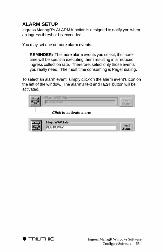
Ingress ManagR Windows Software – 65
�����������
ALARM SETUPIngress ManagR’s ALARM function is designed to notify you whenan ingress threshold is exceeded.
You may set one or more alarm events.
REMINDER: The more alarm events you select, the moretime will be spent in executing them resulting in a reducedingress collection rate. Therefore, select only those eventsyou really need. The most time consuming is Pager dialing.
To select an alarm event, simply click on the alarm event’s icon onthe left of the window. The alarm’s text and TEST button will beactivated.
Configure Software
Click to activate alarm

Ingress ManagR Windows Software66 –
�����������
Once you have enabled an alarm event, you can test it by clickingon the event’s TEST button.
There is a slight difference between the way the POLL and PINGmethods handle alarms. With the PING Method, the ACM-8 hassatisfied all the PING alarm criteria and sets off the alarm as soonas it is pinged. When using the POLL Method, Ingress ManagRhas to compare the events to the criteria and will not set off anyalarms until the POLL alarm criteria has been met.
The ALARM ARMING screen contains several different alarmevents:
• Play.WAV File (page 67)• Display Message (page 67)• Call Pager (page 67)• Log to Database File (page 69)• Send SNMP Traps (page 69)
Configure Software

Ingress ManagR Windows Software – 67
�����������
Play .WAV FileThe Play .WAV File event notifies you audibly by activa-ting a sound file whenever the ingress threshold is
exceeded. The default sound file, included with Ingress ManagR,is ALARM.WAV. If you wish, you may change the tone of thealarm to any type of sound. However, the new .WAV file should belocated in the Ingress ManagR folder.
When you double-click on the event’s filename text box, you areprompted to enter a .WAV filename via a browse dialog.
NOTE: If your system has a sound card, Ingress ManagRwill play the WAV file. If your system does not have a soundcard, Ingress ManagR will use a beep for this event.
The Play .WAV File alarm event obeys the hold off which is set inIDENTIFICATION.
Display MessageThe Display Message event places alarm messages(BLACK text) which contain the Frequency and Ampli-
tude of the offending Ingress point in the STATUS BAR.
The Display Message event obeys the hold off set in IDENTIFICA-TION.
Call PagerThe Call Pager event notifies you via a pager when anIngress threshold is exceeded. You can assign a unique
number to each individual Hub. This is useful if you have techni-cians assigned to specific Hubs and want the alarm to notify thetechnician responsible for that Hub via his pager that there is aproblem (see PAGER NUMBER TAB page 58).
There are several ways that you can set up the Call Pager alarmevent. You can have it simply display the phone number of theHub with the alarm, you can display the last four digits of theHub’s phone number along with the pertinent SST and Node, andyou can even assign internal codes within the call back to yourown specifications.
Configure Software
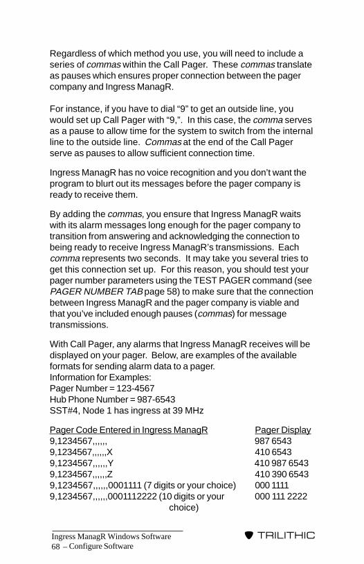
Ingress ManagR Windows Software68 –
�����������
Configure Software
Regardless of which method you use, you will need to include aseries of commas within the Call Pager. These commas translateas pauses which ensures proper connection between the pagercompany and Ingress ManagR.
For instance, if you have to dial “9” to get an outside line, youwould set up Call Pager with “9,”. In this case, the comma servesas a pause to allow time for the system to switch from the internalline to the outside line. Commas at the end of the Call Pagerserve as pauses to allow sufficient connection time.
Ingress ManagR has no voice recognition and you don’t want theprogram to blurt out its messages before the pager company isready to receive them.
By adding the commas, you ensure that Ingress ManagR waitswith its alarm messages long enough for the pager company totransition from answering and acknowledging the connection tobeing ready to receive Ingress ManagR’s transmissions. Eachcomma represents two seconds. It may take you several tries toget this connection set up. For this reason, you should test yourpager number parameters using the TEST PAGER command (seePAGER NUMBER TAB page 58) to make sure that the connectionbetween Ingress ManagR and the pager company is viable andthat you’ve included enough pauses (commas) for messagetransmissions.
With Call Pager, any alarms that Ingress ManagR receives will bedisplayed on your pager. Below, are examples of the availableformats for sending alarm data to a pager.Information for Examples:Pager Number = 123-4567Hub Phone Number = 987-6543SST#4, Node 1 has ingress at 39 MHz
Pager Code Entered in Ingress ManagR Pager Display9,1234567,,,,,, 987 65439,1234567,,,,,,X 410 65439,1234567,,,,,,Y 410 987 65439,1234567,,,,,,Z 410 390 65439,1234567,,,,,,0001111 (7 digits or your choice) 000 11119,1234567,,,,,,0001112222 (10 digits or your 000 111 2222
choice)
Ingress ManagR Windows Software – 69
�����������
NOTE: If you are using the EI-1 Ethernet Interface ratherthan a modem, you can use the IP Addresses of the devicesrather than phone numbers. If you are using the FI-1 FiberInterface or the direct connection method, you may assignany seven digit number you desire.
In the first example (9,1234567,,,,,,), you are merely displaying thephone number of the Hub.
In the second example (9,1234567,,,,,,X), you will get the SST#(4), Node# (1), 0 (which serves as a spacer), followed by the lastfour digits of the Hub phone number (6543).
In the third example (9,1234567,,,,,,Y), you will get the SST# (4),Node# (1), 0 (which serves as a spacer), followed by the Hub’sentire phone number (987-6543).
In the fourth example (9,1234567,,,,,,Z), you will get the SST# (4),Node# (1), 0 (which serves as a spacer), three digits indicating thefrequency of the offending ingress (390) followed by the last fourdigits of the Hub phone number (6543).
Examples five and six are custom pages which you can assign.For example, in example six, the digit 2 might be used to indicatethat it is Hub #2 that has an alarm.
The Call Pager event obeys the hold off set in IDENTIFICATION.
Log to Database FileThe Log to Database File event writes the alarm dataobtained by Ingress ManagR into a log file for future
review or processing. The default filename is ALARM.MDB.
When you double-click on the event’s filename text box, you areprompted to enter a filename via a browse dialog.
Send SNMP TrapsIf you are using Ingress ManagR’s SNMP capability, setthe desired traps (alarms) in the SNMP Tab of the IDEN-
tification window (see page 59). Once the traps are designated,activate this alarm event.
Configure Software

Ingress ManagR Windows Software70 –
�����������
SCAN STRATEGYAt the heart of Ingress ManagR is the SCAN STRATEGY. IngressManagR uses scan strategies to define automatically how you aregoing to monitor your system. The Scan Strategy scripts can beas simple as just having Ingress ManagR POLL a single Hub everyfew hours to as complex as alternating the POLL and PINGmethods throughout the day for a large number of Hubs withdifferent day/night limits and configurations. These scan strate-gies turn your 9580 SSTs, 9581 SSTs and TPXs into a powerfulstatus monitoring system.
REMINDER: Depending on your PC’s configuration, you maynotice a time lag between the Window’s time display and thePC’s real time clock. Use Ingress ManagR’s TIMESYNCHRONIZATION option (see page 151) to eliminate thistime lag.
In this section, you’ll be shown the various scan icons and begiven a walk through for building a basic scan strategy. For ideasfor building more complex strategies, see SAMPLE SCANSTRATEGIES page 133.
To enter the SCAN STRATEGY screen, click on the SETUP Menuand then on SCAN STRATEGIES. This opens the SCAN STRAT-EGY template.
At the top of the SCAN STRATEGY screen are three functionicons: CREATE NEW SCAN STRATEGY, OPEN, SAVE AS. Youmay use these icons or select the desired function under the FILEMenu.
CREATE NEW SCAN STRATEGY - use this iconto build a new scan strategy.
OPEN - use this icon to open an existing ScanStrategy. You can then edit the script.
SAVE AS - use this icon to save the new oredited Scan Strategy.
Configure Software

Ingress ManagR Windows Software – 71
�����������
There are eleven functions which you can use in any combination:
• “Wait Until” • “If...Break”• “Wait For” • “Goto Step”• “Log All to Disk” • “Ping Hub” (ACM-8/NCM-4)• “Check Alarm” • “Config Hub” (ACM-8/NCM-4)• “Scan Hub” • “Delete Step”• “Scan 1 Hub”
Script Step Icon DescriptionEach of the eleven functions is represented by an icon:
“Wait Until” Icon enables you to select a particulartime of day for your script to proceed to the next step.
“Wait For” enables you to select a length of time foryour script to pause before proceeding to the next step.
“Log All to Disk” enables Ingress ManagR to write thescanned data into a file for later review. When using thePOLL Method, all of the data will be logged to the file.When using PING, the alarm data will be logged to thefile. You may also have multiple files which enables youto collect data for individual Hubs.
Configure Software

Ingress ManagR Windows Software72 –
�����������
If you have checked the Maintain Special StrategySingle Record Database “STRATEGY.MDB” in theFILE CONTROL SETTINGS window (see page 33),the data will be saved to a designated database.
“Check Alarm” enables the Alarm Event firing during ascan if a threshold is exceeded. You should have atleast one of these in your strategy script.
“Scan Hub” allows you to access and gather specificdata from a Hub.
“Scan 1 Hub” allows you to dial up and gather specificdata from a Hub. This step maintains the phone link tothe designated Hub rather than hanging up. It is usefulwhen you are constructing a tight loop and do not wantto keep re-dialing the same number.
NOTE: This function is NOT recommended ifyou are using the NCM-4.
“If...Break” enables you to have the scan strategy ignorethe next “Go to Step” command that it encounters if thehour matches the entered one. This is useful to set upmore complex strategies by scheduling various datacollection activities at certain times of the day.
“Go to Step” enables you to build a scan loop by jump-ing the scan back to a particular step.
The two following steps are available for the ACM-8 or NCM-4Only:
“Ping Hub” instructs Ingress ManagR to request (or“ping”) the ACM-8 or NCM-4 to check for any alarmflags. If the ACM-8 or NCM-4 has not noted any alarmssince the previous “ping”, Ingress ManagR will proceeddirectly to the next Hub. If an alarm was noted, the datawill be logged to disk, trigger the Pager Call alarm orwhatever you have designated as the appropriate actionin the event of an alarm based on what you set up (seeIDENTIFICATION SETUP page 35).
Configure Software
Ingress ManagR Windows Software – 73
�����������
“Configure Hub” (used only with ACM-8 or NCM-4)performs the same task as the CONFIGURE tab in theIDENTIFICATION SETUP Menu (see CONFIGUREpage 63).
By adding this icon to the script, you can broaden yourstrategy to be able to switch alarm criteria for the sameHub at different times of the day by assigning different“aliases” or names to the same Hub and then recon-figuring that Hub for different sample rates, thresholdbreaks, etc. This enables you to change ping limitsunder the strategy control.
“Delete Step” enables you to delete or “trash” a functionstep (available for ACM-8, and NCM-4).
Building a Scan StrategyWhen you first open the SCAN STRATEGY screen, you mustdecide whether you are going to OPEN an existing strategy to editor start a NEW strategy.
HOT TIPChapter 12 (see page 133) contains run throughs of the sampleScan Strategies (which came with Ingress ManagR). You canrefer to these to get an idea of just how versatile IngressManagR can be.
NEW STRATEGYTo build a NEW strategy, click on the CREATE SCAN STRATEGYicon or select NEW under the FILE Menu.
To build the strategy, click on the desired icon, drag the icon tothe main window of the screen below Step/Action/Special anddrop the icon in place by releasing the mouse button.
This example illustrates the following scenario for Greenwood Hub:activates alarms, logs all data to disk, waits until 3:52 PM, “pings”Greenwood once, waits for 2 hours, scans one hub for ingress,hangs up the line and waits until the next day at the same time.This scenario only logs or fires alarm events that reach thresholdbreak.
Configure Software
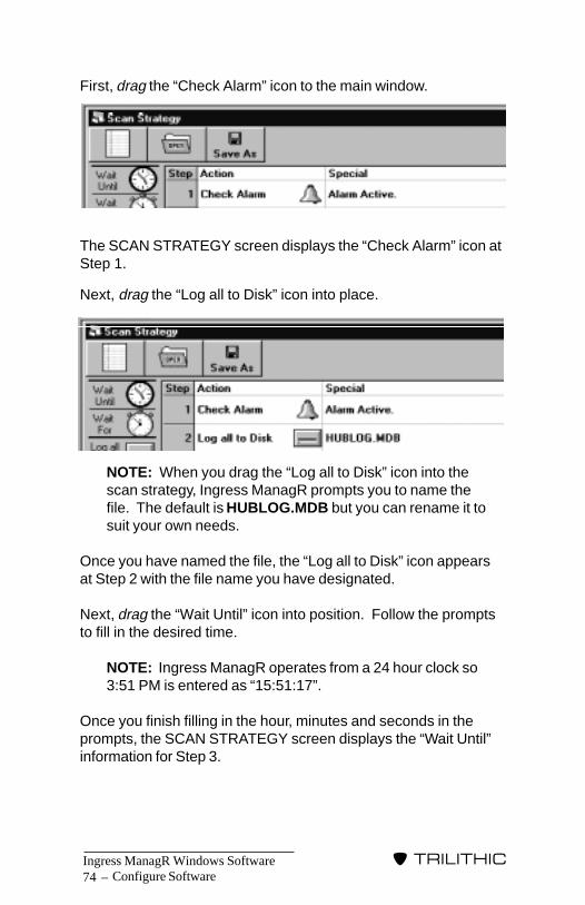
Ingress ManagR Windows Software74 –
�����������
First, drag the “Check Alarm” icon to the main window.
The SCAN STRATEGY screen displays the “Check Alarm” icon atStep 1.
Next, drag the “Log all to Disk” icon into place.
NOTE: When you drag the “Log all to Disk” icon into thescan strategy, Ingress ManagR prompts you to name thefile. The default is HUBLOG.MDB but you can rename it tosuit your own needs.
Once you have named the file, the “Log all to Disk” icon appearsat Step 2 with the file name you have designated.
Next, drag the “Wait Until” icon into position. Follow the promptsto fill in the desired time.
NOTE: Ingress ManagR operates from a 24 hour clock so3:51 PM is entered as “15:51:17”.
Once you finish filling in the hour, minutes and seconds in theprompts, the SCAN STRATEGY screen displays the “Wait Until”information for Step 3.
Configure Software
Ingress ManagR Windows Software – 75
�����������
Repeat the drag & drop process for the “Ping Hub”, “Wait For”“Scan 1 Hub” and “Go to Step” icons. In each case, you will beprompted for the necessary information by Ingress ManagR.
When you have finished the icon drag & drop procedure, yourSCAN STRATEGY screen should look similar to the following:
Configure Software
Ingress ManagR Windows Software76 –
�����������
Configure Software
As you fill in the steps in the main window, you may notice thatthe later steps aren’t visible. To enlarge the window, point yourcursor at the bottom part of the window frame until it turns into adouble vertical arrow and then drag down on the frame.
NOTE: You build the strategy as you go so, if you want touse the “Wait Until” icon first, you need to drag & drop it first.The Scan Strategy executes one step at a time. If the firststep is “Wait Until” 15:51:17, Ingress ManagR will wait until3:51 PM to run the strategy. If it is before that time on theday you set up the strategy, Ingress ManagR will run it onthe same day. If it is after the target time, Ingress ManagRwill not run the strategy until the following day.
HOT TIPYou may edit the building screen at any time during the process.If you need to add a step between two steps already in place(such as steps 2 and 3), you can click on step 3, drag the desirednew icon up to it and a new step 3 will be inserted between step 2and the old step 3.
You can also edit existing steps. For example, if you need tochange the “Wait Until” time in the above sample from 3:51 PM to4:05 PM, you can double click on the text line of “15:51:17”. Thisbrings up the pop up window for the “Wait Until” icon so that yousimply type in the new time. In this case 16:05:00. If you wish tosee which Nodes have been selected in a scan icon, just double-click on the icon.
To delete an existing step from the Scan Strategy, simply drag anddrop any part of the step onto the DELETE (trash can) icon.Recheck your GOTOS after you delete any step.
cursor turns to arrow,drag down frame
Ingress ManagR Windows Software – 77
�����������
Once your strategy is set up the way you want, go to the FILEMenu and select SAVE AS or click on the SAVE AS icon.
After you are satisfied with the script and have saved it, go toSTATUS MONITOR to begin using your Scan Strategy.
REMINDER: If you are building a scan strategy for a singleHub and wish to minimize the time between POLLS, use theSCAN 1 HUB icon. This keeps the phone line to that Hubopen so that Ingress ManagR does not need to keepre-dialing and reconnecting to that location.
OPEN STRATEGYIf you wish to modify or update an existing Scan Strategy, go tothe FILE Menu and select OPEN or click on the OPEN icon.
STATION SETUPIf you are using Ingress ManagR’s SNMP feature (see SNMPCOMPATIBLE page 7 and SNMP TAB page 59), you will need toassign the application level SNMP MIB variables. Go to theSETUP menu and select STATION SETUP.
Configure Software
Ingress ManagR Windows Software78 –
�����������
Configure Software
Fill in the information in the COMPANY OR DOMAIN NAME andPHYSICAL OR LOGICAL LOCATION NAME boxes. This enablesthe recipient of the SNMP traps (such as a system or sectionmanager) to pinpoint which station is sending the SNMP trapinformation.
The STATION SETUP window also enables you to set the diskthresholds for the specific station or PC. For example, you maywant a manager to be notified when the PC has only 200000KBytes of space remaining on the hard drive. If you put thenumber 200000 in the MINIMUM DISK SPACE BEFOREAPPINFO TRAP box, Ingress ManagR sends an SNMP trap whenavailable disk space is at 200000 KBytes or below. This way, youcan make sure disk space remains available for operations anddata collection.
Once you have filled in the three boxes, click the OK button.

Ingress ManagR Windows Software – 79
�����������
STATUSMONITOR
MODE
Status Monitor Mode
IntroductionIngress ManagR permits you to collect data from your 9580/9581system at specified times by using a script developed in theSCAN STRATEGY screen. This is particularly useful if you wishto collect information at specific times of day or at regular inter-vals such as every four hours.
CAUTION: Using an SST’s front panel controls whilescanning the SST via STATUS MONITOR Mode, is notrecommended. This can cause inaccurate data gathering.
Start Status Monitor ModeTo start the STATUS MONITOR Mode, click on the MODE Menuand then on STATUS MONITOR.
OperationOnce you have entered the STATUS MONITOR Mode, you needto open a Scan Strategy which was developed earlier (see SCANSTRATEGY page 70).
� 6
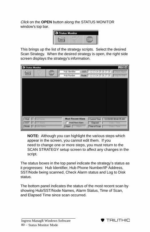
Ingress ManagR Windows Software80 –
�����������
Click on the OPEN button along the STATUS MONITORwindow’s top bar.
This brings up the list of the strategy scripts. Select the desiredScan Strategy. When the desired strategy is open, the right sidescreen displays the strategy’s information.
NOTE: Although you can highlight the various steps whichappear in the screen, you cannot edit them. If youneed to change one or more steps, you must return to theSCAN STRATEGY setup screen to affect any changes in thescript.
The status boxes in the top panel indicate the strategy’s status asit progresses: Hub Identifier, Hub Phone Number/IP Address,SST/Node being scanned, Check Alarm status and Log to Diskstatus.
The bottom panel indicates the status of the most recent scan byshowing Hub/SST/Node Names, Alarm Status, Time of Scan,and Elapsed Time since scan occurred.
Status Monitor Mode
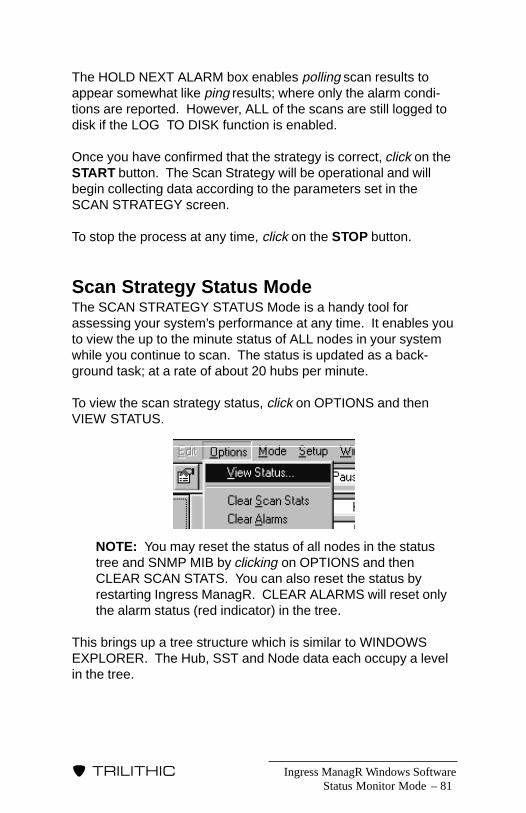
Ingress ManagR Windows Software – 81
�����������
The HOLD NEXT ALARM box enables polling scan results toappear somewhat like ping results; where only the alarm condi-tions are reported. However, ALL of the scans are still logged todisk if the LOG TO DISK function is enabled.
Once you have confirmed that the strategy is correct, click on theSTART button. The Scan Strategy will be operational and willbegin collecting data according to the parameters set in theSCAN STRATEGY screen.
To stop the process at any time, click on the STOP button.
Scan Strategy Status ModeThe SCAN STRATEGY STATUS Mode is a handy tool forassessing your system’s performance at any time. It enables youto view the up to the minute status of ALL nodes in your systemwhile you continue to scan. The status is updated as a back-ground task; at a rate of about 20 hubs per minute.
To view the scan strategy status, click on OPTIONS and thenVIEW STATUS.
NOTE: You may reset the status of all nodes in the statustree and SNMP MIB by clicking on OPTIONS and thenCLEAR SCAN STATS. You can also reset the status byrestarting Ingress ManagR. CLEAR ALARMS will reset onlythe alarm status (red indicator) in the tree.
This brings up a tree structure which is similar to WINDOWSEXPLORER. The Hub, SST and Node data each occupy a levelin the tree.
Status Monitor Mode

Ingress ManagR Windows Software82 –
�����������
Status Monitor Mode
When the tree first appears, it shows only the Hub level.
To move between the levels, use the same procedure you use tomove around in WINDOWS EXPLORER. When you click on aspecific Node, the window displays the current status, last alarmand the total alarms for that Node.
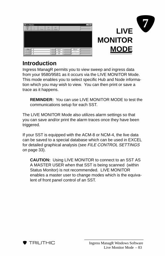
Ingress ManagR Windows Software – 83
�����������
LIVEMONITOR
MODE
Live Monitor Mode
IntroductionIngress ManagR permits you to view sweep and ingress datafrom your 9580/9581 as it occurs via the LIVE MONITOR Mode.This mode enables you to select specific Hub and Node informa-tion which you may wish to view. You can then print or save atrace as it happens.
REMINDER: You can use LIVE MONITOR MODE to test thecommunications setup for each SST.
The LIVE MONITOR Mode also utilizes alarm settings so thatyou can save and/or print the alarm traces once they have beentriggered.
If your SST is equipped with the ACM-8 or NCM-4, the live datacan be saved to a special database which can be used in EXCELfor detailed graphical analysis (see FILE CONTROL SETTINGSon page 33).
CAUTION: Using LIVE MONITOR to connect to an SST ASA MASTER USER when that SST is being scanned (withinStatus Monitor) is not recommended. LIVE MONITORenables a master user to change modes which is the equiva-lent of front panel control of an SST.
� 7
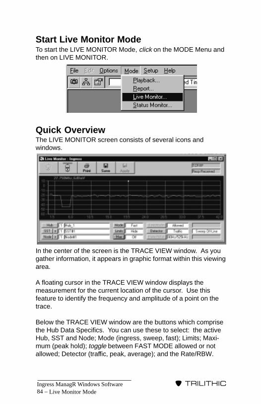
Ingress ManagR Windows Software84 –
�����������
Start Live Monitor ModeTo start the LIVE MONITOR Mode, click on the MODE Menu andthen on LIVE MONITOR.
Quick OverviewThe LIVE MONITOR screen consists of several icons andwindows.
In the center of the screen is the TRACE VIEW window. As yougather information, it appears in graphic format within this viewingarea.
A floating cursor in the TRACE VIEW window displays themeasurement for the current location of the cursor. Use thisfeature to identify the frequency and amplitude of a point on thetrace.
Below the TRACE VIEW window are the buttons which comprisethe Hub Data Specifics. You can use these to select: the activeHub, SST and Node; Mode (ingress, sweep, fast); Limits; Maxi-mum (peak hold); toggle between FAST MODE allowed or notallowed; Detector (traffic, peak, average); and the Rate/RBW.
Live Monitor Mode
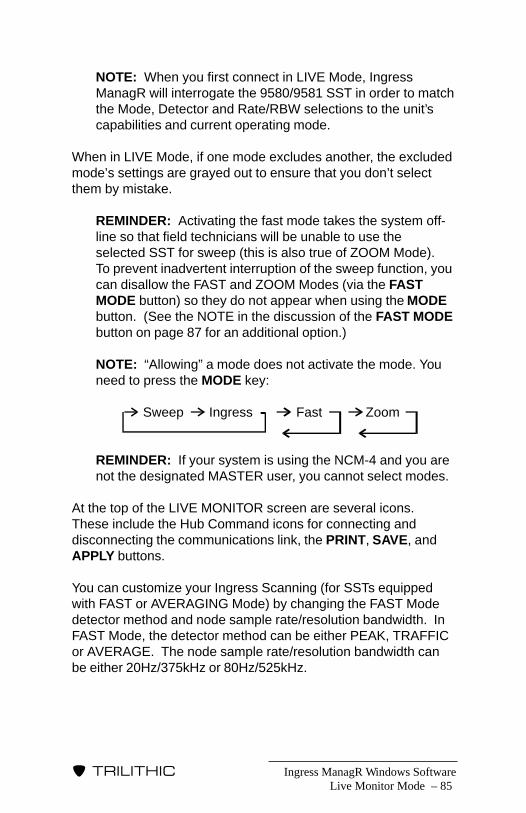
Ingress ManagR Windows Software – 85
�����������
NOTE: When you first connect in LIVE Mode, IngressManagR will interrogate the 9580/9581 SST in order to matchthe Mode, Detector and Rate/RBW selections to the unit’scapabilities and current operating mode.
When in LIVE Mode, if one mode excludes another, the excludedmode’s settings are grayed out to ensure that you don’t selectthem by mistake.
REMINDER: Activating the fast mode takes the system off-line so that field technicians will be unable to use theselected SST for sweep (this is also true of ZOOM Mode).To prevent inadvertent interruption of the sweep function, youcan disallow the FAST and ZOOM Modes (via the FASTMODE button) so they do not appear when using the MODEbutton. (See the NOTE in the discussion of the FAST MODEbutton on page 87 for an additional option.)
NOTE: “Allowing” a mode does not activate the mode. Youneed to press the MODE key:
REMINDER: If your system is using the NCM-4 and you arenot the designated MASTER user, you cannot select modes.
At the top of the LIVE MONITOR screen are several icons.These include the Hub Command icons for connecting anddisconnecting the communications link, the PRINT, SAVE, andAPPLY buttons.
You can customize your Ingress Scanning (for SSTs equippedwith FAST or AVERAGING Mode) by changing the FAST Modedetector method and node sample rate/resolution bandwidth. InFAST Mode, the detector method can be either PEAK, TRAFFICor AVERAGE. The node sample rate/resolution bandwidth canbe either 20Hz/375kHz or 80Hz/525kHz.
Live Monitor Mode
Sweep Ingress Fast Zoom

Ingress ManagR Windows Software86 –
�����������
Live Monitor Mode
OperationThere are several actions required for using the LIVE MONITORMode.
CONNECT TO HUBIn order to use the LIVE MONITOR Mode to collect current data,you must have your connection method set up (see CONNEC-TION METHOD page 26).
Once the hardware is set up, click on the CONNECT TO HUBicon.
The HUB ID window pops up. Select the desired Hub, SST andNode and then click on the CLOSE button. This enables IngressManagR to establish the communications link between your PCand 9580/9581 system.
NOTE: You can confirm the activity by observing theprogress messages in the STATUS BAR at the bottom of thescreen. In addition, if you have checked the SHOW CMD/RESP STATUS command in the OPTIONS Menu,CONNECTION METHOD and COMMAND/RESPONSEboxes appear in the upper RIGHT corner of the LIVEMONITOR window.
HUB DATA SPECIFICSOnce you have connected to the Hub, you can select the specificdata you wish to collect using the buttons at the bottom of thescreen.
The buttons include:
Hub – Selects the active Hub from list.
Ingress ManagR Windows Software – 87
�����������
SST – Selects the active SST from list. Use the > buttonto go to the next SST in the current Hub.
Node – Selects the active Node from list. Use the > buttonto go to the next Node in the current SST.
NOTE: When cycling through the available hubs, SSTs andnodes, Ingress ManagR will attempt to maintain it’s connec-tion. This can be a problem if it encounters a hub, SST ornode that is not being used but is not labelled as such.Encountering these non-existent components will causeerror messages and will cause the LIVE MODE to be dis-connected. To make sure that LIVE MODE cycles throughthe available components correctly, make sure to renamesuch components as “UNUSED”. This way, LIVE MODEwill simply pass on to the next component.
Mode – Selects the desired mode: sweep, ingress(normal), fast, or zoom (if fast and zoom areallowed under the FAST MODE button.
NOTE: If you’re connected to an NCM-4 butare not the Master, you will NOT be able tochange the mode.
Limits – Use to hide or display the current limits for theselected Node. Use the “draw first” and “drawlast” setting to bring the desired trace forward.
Max – Displays the peak value of ingress. This isuseful for capturing and holding the peak valueof infrequent/intermittent signals (FAST Modeingress data already supplies peak valuesunless the detector method is AVERAGE).
Fast Mode – Disables the FAST Mode feature. When itdisplays “NOT ALLOWED”, FAST Mode andZOOM Mode will not show as a setting underthe MODE button.
NOTE: You may wish to disallow ZOOM Moderegardless of this setting. You can do this byunchecking ALLOW ZOOM MODE in theOPTIONS Menu.
Live Monitor Mode
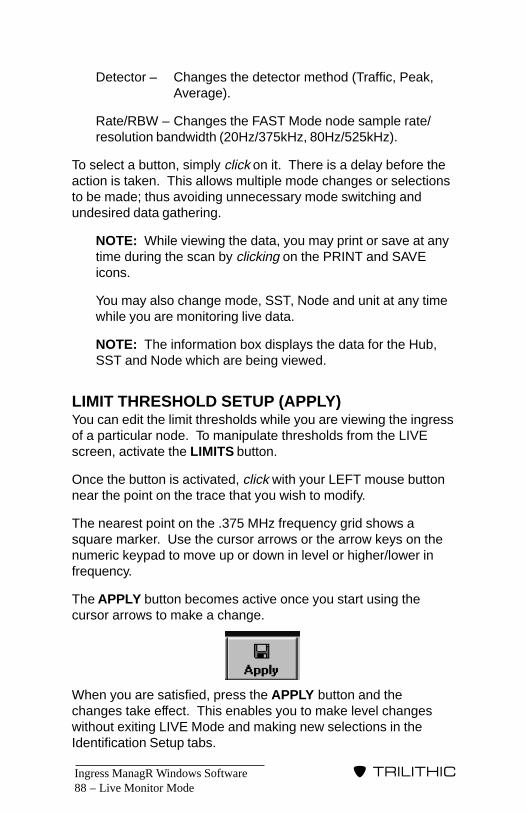
Ingress ManagR Windows Software88 –
�����������
Detector – Changes the detector method (Traffic, Peak,Average).
Rate/RBW – Changes the FAST Mode node sample rate/resolution bandwidth (20Hz/375kHz, 80Hz/525kHz).
To select a button, simply click on it. There is a delay before theaction is taken. This allows multiple mode changes or selectionsto be made; thus avoiding unnecessary mode switching andundesired data gathering.
NOTE: While viewing the data, you may print or save at anytime during the scan by clicking on the PRINT and SAVEicons.
You may also change mode, SST, Node and unit at any timewhile you are monitoring live data.
NOTE: The information box displays the data for the Hub,SST and Node which are being viewed.
LIMIT THRESHOLD SETUP (APPLY)You can edit the limit thresholds while you are viewing the ingressof a particular node. To manipulate thresholds from the LIVEscreen, activate the LIMITS button.
Once the button is activated, click with your LEFT mouse buttonnear the point on the trace that you wish to modify.
The nearest point on the .375 MHz frequency grid shows asquare marker. Use the cursor arrows or the arrow keys on thenumeric keypad to move up or down in level or higher/lower infrequency.
The APPLY button becomes active once you start using thecursor arrows to make a change.
When you are satisfied, press the APPLY button and thechanges take effect. This enables you to make level changeswithout exiting LIVE Mode and making new selections in theIdentification Setup tabs.
Live Monitor Mode

Ingress ManagR Windows Software – 89
�����������
If you wish to turn the cursor OFF, simply click with the RIGHTmouse button. You can also hide the traces by selecting HIDEwith the LIMITS button.
You can set thresholds in any of the SST’s detector modes. Ifdesired, you can build a long term picture of the ingress on anode by using the PEAK HOLD feature before you edit the limitsthreshold for a specific node.
PRINT DATAWhile you are monitoring the live data, you can print any tracethat you see as it happens. Click on the PRINT icon.
Your print out depends on what parameters you selected for thescan.
If you selected the MAX icon, the print out will contain the STARTand STOP times which were used to accumulate the peakreadings of the trace.
NOTE: The STOP time is always the moment that youclick on the PRINT icon.
SAVE COMMANDAs you monitor the live data, you may wish to save the informa-tion to a file for later review. Click on the SAVE icon to save thecurrently displayed data as a database record.
Data is saved (appended) to a file named QUICKSAV.SST. Thisis a special file type (proprietary format) that contains sweep andingress data as well as current alarm threshold data. If the modeis INGRESS or FAST, the ingress data is also saved (appended)to a file named QUICKSAV.MDB in the standard format. Eitherfile may be played back at a later time.
Live Monitor Mode

Ingress ManagR Windows Software90 –
�����������
NOTE: You can use the PLAYBACK Menu to go into the fileto review and parse out portions of the file. You can deletethese files at any time using Windows Explorer (see page 91for more information regarding PLAYBACK operations).
MESSAGE DISPLAYThe right corner has a display area where messages may bedisplayed during the LIVE scan. The possible messages are:
• Connecting – This message is displayed while IngressManagR is establishing a connection and interrogating theSST abou its features and setup.
• Sweep Off-Line – When the SST is selected to be in FASTMode, field pieces (SSR, RSVP, RSVPII) cannot sweep.
• TPX In Use (NCM-4) – When a Master User locks a TPXon a bank, ALL other banks are frozen to the old data untilthe Master User logs off the NCM-4.
DISCONNECT THE HUBWhen you have finished scanning, printing and/or saving thedata, you need to close the link. Click on the DISCONNECTFROM HUB icon.
The STATUS BAR should indicate that LIVE MONITOR Modehas disconnected successfully and shut down.
Live Monitor Mode

Ingress ManagR Windows Software – 91
�����������
PLAYBACKSCREEN
Playback Screen
IntroductionYou use the PLAYBACK screen to review records which weretaken via the STATUS MONITOR Mode or saved from a LIVEMONITOR Mode session.
To start the PLAYBACK screen, click on the MODE Menu andthen on PLAYBACK.
Quick OverviewThe PLAYBACK screen consists of several features and func-tions.
WARNING: Attempting to Playback database files (includingarchive files) that are being updated by an executing ScanStrategy may result in unpredictable behavior and/or dataloss, and is not recommended. The recommended approachto viewing such files is to use Windows Explorer to make atemporary copy of the a database file for use with Playback.
� 8
Ingress ManagR Windows Software92 –
�����������
In the center of the screen is the TRACE VIEW window. Onceyou open a file, the information appears in graphic format withinthis viewing area.
A floating cursor in the TRACE VIEW window displays themeasurement for the current location of the cursor. As you movethe cursor around the trace, you will note that the measurementchanges.
Above the TRACE VIEW window are several icon controls.These include the OPEN, CLOSE and PRINT buttons. To theright of the buttons are three RECORD icons which you can useto parse out and save individual trace records of interest.
Below the TRACE VIEW window are several controls and textboxes which comprise the RECORD INFORMATION ANDCONTROL panel. These controls enable you to control playbackfunctions and configure how the trace records of the selected filewill be filtered and viewed during PLAYBACK.
OperationTo perform the PLAYBACK screen’s functions, click on thevarious buttons and icons contained in the screen. Several majorfunctions, such as opening or closing a file or exiting, may alsobe accomplished using the menus.
OPEN FILEBefore you can use the PLAYBACK screen to view and printrecords, you must first open a file or database. Click on theOPEN icon or the OPEN command under FILE.
Ingress ManagR opens a browse dialogue box which contains alist of existing files. PLAYBACK Mode can play .MDB databasefiles (the data format used by Ingress ManagR 3.x) and .SST files(data format used by Ingress ManagR 2.x and earlier). Select thedesired file and click the dialogue box’s OPEN button. Thegraphical representation of the first trace record of the selectedfile appears in the TRACE VIEW window.
Playback Screen

Ingress ManagR Windows Software – 93
�����������
Playback Screen
VIEWING TRACE DATATrace records are viewed one at a time. Text boxes in theRECORD INFORMATION AND CONTROL panel display:
• Hub, SST and Node each trace record represents
• Mode (Ingress, Sweep or Zoom)
• Time Stamp which indicates when the trace data wasgathered
• Record Number relative to the total number of records inthe file
If you wish the alarm limit traces to be shown along with theingress trace, click the LIMITS button. Select DRAW FIRST tohave the alarm limits drawn first (ingress trace on top). SelectDRAW LAST to have the alarm limits drawn on top of the ingresstrace or HIDE to show only the ingress trace.
NOTE: Database files do NOT contain alarm limit data. Thealarm limits defined for that Hub/SST/Node in the Identifica-tions dialogue are used, providing that the Hub Name in thetrace record is defined in Identifications. If the Hub Name isnot defined, no alarm limit traces will be shown.
If necessary, you can zoom in on a displayed trace to enlarge aspecific area so that you can view it in detail. To zoom in, placethe cursor on the section of the trace you wish to view. Click &drag with the LEFT mouse button to outline the desired section.Repeat this procedure until the section is the size you need. Toreset the image to normal resolution, click once with the RIGHTmouse button.
PLAYBACK CONTROLUse the PLAY button to sequence through the records automati-cally.
Use the MODE button to select single or repetitive play.
Use the SPEED slider to adjust playback speed. Speed mayalso be set from the OPTIONS Menu, in which case it is specifiedas the number of seconds per frame (record).
Ingress ManagR Windows Software94 –
�����������
Playback Screen
RECORD SELECTIONWhen the selected file is not actively being played back, severaltrace record selection features are enabled.
Click or click and drag the SELECT scroll bar to scan quicklythrough the records to find an ingress outbreak or records of aspecific time stamp.
Use the record filter to restrict playback or record selection to asingle node of interest. Click the FILTER button to select be-tween ALL NODES (no restrictions) and THIS NODE (onlydisplay instances of the currently displayed node). With the filterset to THIS NODE, the SELECT scroll bar enables you to scanthrough the file as if there were only records pertaining to thenode in which you are interested. This is useful if you are tryingto track the ingress for a particular node and your file alsocontains data from hundreds of other nodes.
As an alternative to using the SELECT scroll bar with the filter setto THIS NODE, you may also use the FIND NEXT and FINDPREVIOUS commands in the EDIT Menu. Selecting FIND NEXT(or pressing the F3 key) sets the filter to THIS NODE andsearches for the next record of the currently displayed node.Selecting FIND PREVIOUS (or pressing SHIFT + the F3 key)sets the filter to THIS NODE and searches for the previousrecord of the currently displayed node.
Use the HUB button to select from a list of Hubs in the PLAY-BACK file. Use the SST button to select from a list of the SSTs inthe selected Hub. Use the NODE button to select from a list ofNodes in the selected SST. All three buttons access the samenode selection dialogue, although with Hub/SST choice restric-tions as appropriate. After selecting your choice of Hub/SST/Node, the file will be searched to find the next record of that nodeand the trace record will be displayed. The THIS NODE recordfilter will be selected automatically.
NOTE: A table of Hubs, SSTs and Nodes, represented inthe selected file, is generated the first time the HUB, SST orNODE button is accessed after the file is selected. Thisprocess may take several seconds depending on the numberof records in the file.
Ingress ManagR Windows Software – 95
�����������
Playback Screen
PRINT PLAYBACK INFORMATIONOnce the desired record trace and/or alarm trace event is dis-played in the TRACE VIEW window, you can print it out byclicking on the PRINT icon.
SORT RECORDSA single file developed in the LIVE MONITOR and STATUSMONITOR Modes may contain numerous records reflecting allthree modes (ingress, sweep, zoom). You may choose toseparate or parse out the records for more convenient filemanagement (i.e. put all ingress records together or combine allrecords taken from a specific node).
The PLAYBACK screen has three RECORD icons which you canuse to parse out and save your records.
The first icon can be ingress ONLY and is saved in a database*.MDB file format. You use this MDB format to collect the ingressdata for later viewing and comparison when you don’t want totake the time to view the data in LIVE Mode.
The middle icon can be sweep or ingress records in an *.SST fileformat.
Use the third icon for sweep records.
HOT TIPThese sweep records can then be reviewed by theSweepSaveR software available from Trilithic (1-800-344-2412). SweepSaveR is designed to manage SSR-9580Sweep Data Logs.
NOTE: If you intend to sort and save sweep records foruse by SweepSaver, we recommend that you keep thefile name of the sweep icon limited to eight characters.
Change File NameYou can change the names of the records saved by each of theRECORD icons.

Ingress ManagR Windows Software96 –
�����������
Playback Screen
RIGHT click on the DISK icon of the record you wish to rename.For example, if you wish to change the name of the file saved tothe SweepSaveR SORT RECORD icon, right click on the thirdicon, SWEEPSAVE (SSTSWEEP.SWP).
The TEXT box to the right of the icons, which was grayed out,becomes active. Double-click on the TEXT box and make thedesired change.
NOTE: Do NOT try to add an extension to the file namesince Ingress ManagR does this for you. In fact, IngressManagR does NOT accept a period as part of the file name.
SAVE A TRACETo save a record to one of the SORT RECORD icons, positionthe cursor on the graph in the TRACE VIEW window. Click andhold down the RIGHT mouse button. The cursor changes to ahand holding a piece of paper. Continue to hold down the mousebutton and drag the cursor to the desired RECORD icon. Oncelocated at the icon, release the mouse button. When this proce-dure is completed, the STATUS BAR at the bottom of the screenindicates RECORD SAVED.
CLOSE FILEOnce you have finished with a particular file, you can close it byclicking on the CLOSE button. You can then open another file orexit from the PLAYBACK screen.
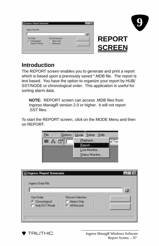
Ingress ManagR Windows Software – 97
�����������
REPORTSCREEN
Report Screen
IntroductionThe REPORT screen enables you to generate and print a reportwhich is based upon a previously saved *.MDB file. The report istext based. You have the option to organize your report by HUB/SST/NODE or chronological order. This application is useful forsorting alarm data.
NOTE: REPORT screen can access .MDB files fromIngress ManagR version 2.0 or higher. It will not report.SST files.
To start the REPORT screen, click on the MODE Menu and thenon REPORT.
� 9
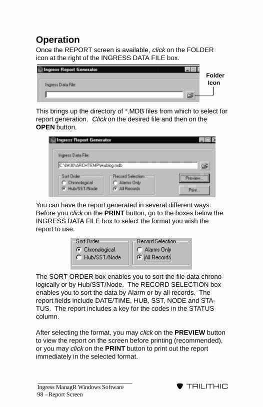
Ingress ManagR Windows Software98 –
�����������
OperationOnce the REPORT screen is available, click on the FOLDERicon at the right of the INGRESS DATA FILE box.
This brings up the directory of *.MDB files from which to select forreport generation. Click on the desired file and then on theOPEN button.
You can have the report generated in several different ways.Before you click on the PRINT button, go to the boxes below theINGRESS DATA FILE box to select the format you wish thereport to use.
The SORT ORDER box enables you to sort the file data chrono-logically or by Hub/SST/Node. The RECORD SELECTION boxenables you to sort the data by Alarm or by all records. Thereport fields include DATE/TIME, HUB, SST, NODE and STA-TUS. The report includes a key for the codes in the STATUScolumn.
After selecting the format, you may click on the PREVIEW buttonto view the report on the screen before printing (recommended),or you may click on the PRINT button to print out the reportimmediately in the selected format.
Report Screen
Folder Icon

Ingress ManagR Windows Software – 99
�����������
ARCHIVER
�10
IntroductionIngress ManagR’s ArchiveR is a software utility which enablesyou to store the data which accumulates in Ingress ManagR’sdatabase (.mdb) files permanently anywhere on your network.ArchiveR provides a means for you to schedule regular storageevents of as many files as you desire at the times best suited toyour system needs.
ArchiveR enables you to store your database files permanentlylocally, out on the network or other storage location (such as adedicated file or library computer). It also enables you to controlthe size of your database files so that you don’t have to worryabout files that are too large and cumbersome to manipulate.
Once ArchiveR has stored the data permanently, it clears thetemporary files so that you won’t need to worry about overflowingand losing important data. It also prevents storage of duplicatedata. ArchiveR is fully network compatible and is designed to runin the background on the computer running Ingress ManagR. Itcan back up files to any drive in your network. Ingress ManagRcan deposit new data even while ArchiveR is pulling data sinceArchiveR will get the new information at the time of the nextscheduled event.
NOTE: In addition to your ArchiveR events, Ingress ManagRuses hidden ArchiveR functions to speed up data gathering(see ArchiveR FIFO Management page 101).
ArchiveR

Ingress ManagR Windows Software100 –
�����������
If Ingress ManagR has been configured to allow ArchiveR toperform its database maintainence function, the ArchiveR utilitywill be started automatically and stopped with Ingress ManagR.
To start ArchiveR manually, go to the Start menu, select Pro-grams, the Trilithic group and then click on Trilithic ArchiveR.Once ArchiveR has started, a file cabinet icon will appear in thewindows TASK BAR. To open the ArchiveR Display, click onceon the TASK BAR icon or right click on the icon and select OpenArchiveR Display.
If the NEW and other buttons appear “grayed out”, check to see ifthe RUN SCHEDULER is check marked. If so, simply click onthe box and you will be able to access Archiver’s function but-tons.
ArchiveR
Ingress ManagR Windows Software – 101
�����������
WARNING: NEVER archive the LIVE, STRATEGY or PLAY-BACK databases. Ingress ManagR uses these databases.If you accidently do archive one of these and the Excelmacros no longer work for ApplinkR, delete the LIVE.MDB,STRATEGY.MDB, or PLAYBACK.MDB file that is no longerworking and let Ingress ManagR recreate it.
ArchiveR FIFO ManagementWhen a FIFO file reaches its maximum, Ingress ManagR acti-vates ArchiveR and passes the FIFO path/filename and theamount of FIFO records to archive. ArchiveR removes the oldestrecords from the FIFO and places them in a temporary hold filewith the same name as the FIFO (for example, castleton.mdbFIFO becomes castleton.mdb in the temporary hold file). This fileis located in the directory below Ingress ManagR, i.e.:
c:/Program Files\Ingress ManagR 3.0\ARCHTEMP
At the scheduled event (see Basic Operation, page 102),ArchiveR copies the temporary holding files into permanentstorage and empties or zeroes the temporary file.
ArchiveR OverviewArchiveR consists of several tabs which include ARCHIVEEVENTS, HISTORY, LOG and HELP.
The EVENTS tab is used to edit the settings for the events. TheEDIT buttons are below and include: NEW, REMOVE,REMOVE ALL, RESET TIME and MANUAL. This tab alsoincludes the schedule settings: RUN SCHEDULER, AUTO RUNSCHEDULER ON SETUP, SOURCE FILE NAME box, DESTINA-TION ROOT NAME box, a box for entering HOURS and boxes toindicate DAYS OF THE WEEK.
The HISTORY tab displays the date and time that each of theevents was last performed.
The LOG tab displays what ArchiveR is doing with regard to howmany records are being archived, the success of the archivingoperation, how long it is taking, etc.
ArchiveR
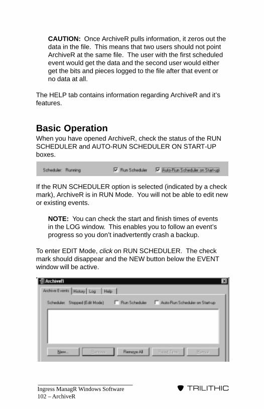
Ingress ManagR Windows Software102 –
�����������
CAUTION: Once ArchiveR pulls information, it zeros out thedata in the file. This means that two users should not pointArchiveR at the same file. The user with the first scheduledevent would get the data and the second user would eitherget the bits and pieces logged to the file after that event orno data at all.
The HELP tab contains information regarding ArchiveR and it’sfeatures.
Basic OperationWhen you have opened ArchiveR, check the status of the RUNSCHEDULER and AUTO-RUN SCHEDULER ON START-UPboxes.
If the RUN SCHEDULER option is selected (indicated by a checkmark), ArchiveR is in RUN Mode. You will not be able to edit newor existing events.
NOTE: You can check the start and finish times of eventsin the LOG window. This enables you to follow an event’sprogress so you don’t inadvertently crash a backup.
To enter EDIT Mode, click on RUN SCHEDULER. The checkmark should disappear and the NEW button below the EVENTwindow will be active.
ArchiveR
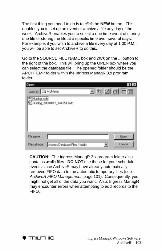
Ingress ManagR Windows Software – 103
�����������
ArchiveR
The first thing you need to do is to click the NEW button. Thisenables you to set up an event or archive a file any day of theweek. ArchiveR enables you to select a one time event of storingone file or storing the file at a specific time over several days.For example, if you wish to archive a file every day at 1:00 P.M.,you will be able to set ArchiveR to do this.
Go to the SOURCE FILE NAME box and click on the ... button tothe right of the box. This will bring up the OPEN box where youcan select the database file. The opened folder should be theARCHTEMP folder within the Ingress ManagR 3.x programfolder.
CAUTION: The Ingress ManagR 3.x program folder alsocontains .mdb files. DO NOT use these for your scheduleevents since ArchiveR may have already automaticallyremoved FIFO data to the automatic temporary files (seeArchiveR FIFO Management, page 101). Consequently, youmight not get all of the data you want. Also, Ingress ManagRmay encounter errors when attempting to add records to theFIFO.
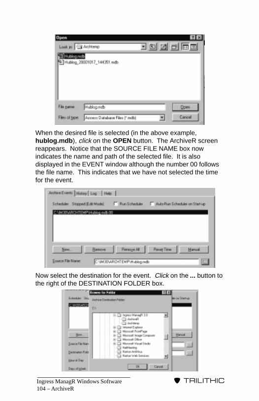
Ingress ManagR Windows Software104 –
�����������
ArchiveR
When the desired file is selected (in the above example,hublog.mdb), click on the OPEN button. The ArchiveR screenreappears. Notice that the SOURCE FILE NAME box nowindicates the name and path of the selected file. It is alsodisplayed in the EVENT window although the number 00 followsthe file name. This indicates that we have not selected the timefor the event.
Now select the destination for the event. Click on the ... button tothe right of the DESTINATION FOLDER box.
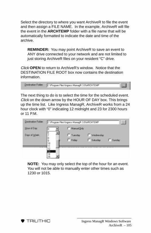
Ingress ManagR Windows Software – 105
�����������
ArchiveR
Select the directory to where you want ArchiveR to file the eventand then assign a FILE NAME. In the example, ArchiveR will filethe event in the ARCHTEMP folder with a file name that will beautomatically formatted to indicate the date and time of thearchive.
REMINDER: You may point ArchiveR to save an event toANY drive connected to your network and are not limited tojust storing ArchiveR files on your resident “C” drive.
Click OPEN to return to ArchiveR’s window. Notice that theDESTINATION FILE ROOT box now contains the destinationinformation.
The next thing to do is to select the time for the scheduled event.Click on the down arrow by the HOUR OF DAY box. This bringsup the time list. Like Ingress ManagR, ArchiveR works from a 24hour clock with “0” indicating 12 midnight and 23 for 2300 hoursor 11 P.M.
NOTE: You may only select the top of the hour for an event.You will not be able to manually enter other times such as1230 or 1015.

Ingress ManagR Windows Software106 –
�����������
ArchiveR
In the example, the event is scheduled for 1 P.M. so “13” or 1300hours is selected. Note that the EVENT window now displays thenumber 13 after the event file.
Once the hour is designated, select the day or days that ArchiveRis to run the event. In the example, the event is scheduled forFriday.
Your final ArchiveR event tab will resemble the following:
Once the event has been performed, click on the LOG tab toview the event’s the activity. Entries which end in “FIFO”, indicatethat Ingress ManagR FIFOs were cleaned up automatically in thebackground (see FIFO FILE LIMITING page 8). Entries endingwith “ARCHIVE” indicate scheduled or manual archive events.

Ingress ManagR Windows Software – 107
�����������
ArchiveR
You may add additional events for different files, times and datesby clicking NEW and repeating the procedure. Once you havescheduled the desired events, go back to the OPERATIONSMenu and select RUN SCHEDULER (checkmark appears).
When you are finished setting up ArchiveR, click on the CLOSEbutton in the upper right corner of the ArchiveR window. IfIngress ManagR is active, ArchiveR will remain active in thebackground.
Additional Operation InformationIn addition to the basic operation, ArchiveR has several otherfeatures.
EDIT BUTTONSThe EVENT window also has several edit buttons:
• New - enables user to build a scheduleevent.
• Remove - select an event in the EVENTwindow and click this button to deleteit from the event schedule.
• Remove All - click this button to deleteALL of the events in the event schedule.
• Reset Time - click this button to reset theArchiveR event completed flags. This isuseful if you stop ArchiveR, shut theprogram down, restart it and wish it toarchive an event that you have alreadyarchived that day.
• Manual - use this button to start theschedule immediately. Useful fortesting ArchiveR.

Ingress ManagR Windows Software108 –
�����������
ArchiveR
LOG TABArchiveR keeps track of its activities via the LOG window. If youwish to delete the log data, click the CLEAR LOG button below thelog event window.
You may also store the activity log in a file for later review. Click onthe LOG TO FILE box so that a check mark appears. The log datawill be written to a file named arclog.txt which is stored in theArchiveR program folder.
CAUTION: The data in the arclog.txt file is cumulative and isNOT emptied each time ArchiveR is restarted. Over time, thefile may become quite large so it is better to use it for trouble-shooting purposes only.
SCHEDULER BOXESThe ARCHIVE EVENTS tab includes two scheduler boxes:
• Run Scheduler - Toggles ArchiveR between the RUN andEDIT Modes. When checkmarked, ArchiveR is in the RUNMode.
• Auto-Run Scheduler on Start-up - When checked, ArchiveRruns the schedule automatically.

Ingress ManagR Windows Software – 109
�����������
VieweR
IntroductionVieweR permits you to view sweep and ingress data from your9580/9581 as it occurs. This enables you to select specific Huband Node information which you may wish to view. You can thenprint a trace as it happens.
REMINDER: You can use VieweR to test the communica-tions setup for each SST.
VieweR also utilizes alarm settings so that you can print thealarm traces once they have been triggered.
CAUTION: Using VieweR to connect to an SST AS AMASTER USER when that SST is being scanned (withinIngress ManagR Status Monitor) is not recommended.VieweR enables a master user to change modes which is theequivalent of front panel control of an SST.
SetupTo start VieweR, go to the folder in which it is installed (i.e.TRILITHIC PROGRAM GROUP) and click on VieweR. Once theprogram’s window opens, you will need to set up the identificationfile so that you can connect to the desired SST unit. The easiestway is to import an existing Identification file from IngressManagR. The IMPORT command brings in an identification filefrom Ingress ManagR which overwrites VieweR’s local (see page116) identification file. This file can then be edited as needed.
NOTE: If you are not using Ingress ManagR or, if youprefer to create different connection settings, you canbuild an identification file within VieweR (see ADDITIONALINFORMATION, page 116).
VIEWER
�11
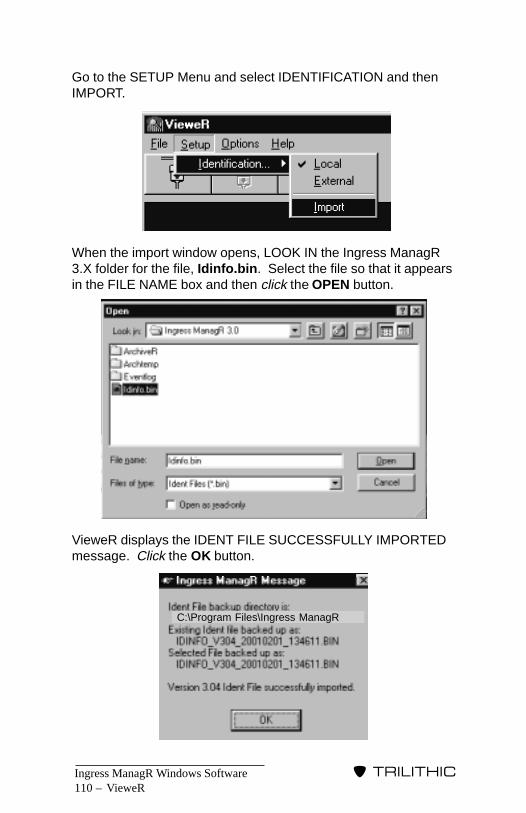
Ingress ManagR Windows Software110 –
�����������
VieweR
Go to the SETUP Menu and select IDENTIFICATION and thenIMPORT.
When the import window opens, LOOK IN the Ingress ManagR3.X folder for the file, Idinfo.bin. Select the file so that it appearsin the FILE NAME box and then click the OPEN button.
VieweR displays the IDENT FILE SUCCESSFULLY IMPORTEDmessage. Click the OK button.
C:\Program Files\Ingress ManagR

Ingress ManagR Windows Software – 111
�����������
VieweR
Once the IDENTIFICATION file has been imported, click on theCONNECT TO HUB icon to start VieweR.
Quick OverviewVieweR consists of several icons and windows.
In the center of the screen is the TRACE VIEW window. As yougather information, it appears in graphic format within this viewingarea.
NOTE: If you wish to expand the size of the TRACE VIEW,double-click anywhere on the graph. To restore the graphto the original size, double-click on it again.
A floating cursor in the TRACE VIEW window displays themeasurement for the current location of the cursor. Use thisfeature to identify the frequency and amplitude of a point on thetrace.
Cloverdale
VieweR: Cloverdale - SST#1 - Node#1

Ingress ManagR Windows Software112 –
�����������
VieweR
Below the TRACE VIEW window are the buttons which comprisethe Hub Data Specifics. You can use these to select: the activeHub, SST and Node; Mode (ingress, sweep, fast, zoom); Limits;Maximum (peak hold); toggle between FAST MODE allowed ornot allowed; Detector (traffic, peak, average); and the Rate/RBW.
NOTE: When you first connect to VieweR, the program willinterrogate the 9580/9581 SST in order to match the Mode,Detector and Rate/RBW selections to the unit’s capabilitiesand current operating mode.
When in VieweR, if one mode excludes another, the excludedmode’s settings are grayed out to ensure that you don’t selectthem by mistake.
REMINDER: Activating the fast mode takes the system off-line so that field technicians will be unable to use theselected SST for sweep (this is also true of ZOOM Mode).To prevent inadvertent interruption of the sweep function, youcan disallow the FAST and ZOOM Modes (via the FASTMODE button) so they do not appear when using the MODEbutton.
NOTE: “Allowing” a mode does not activate the mode. Youneed to press the MODE key:
REMINDER: If your system is using the NCM-4 and you arenot the designated MASTER user, you cannot select modes.
At the top of the VieweR screen are several icons. These includethe Hub Command icons for connecting and disconnecting thecommunications link as well as the PRINT button.
You can customize your Ingress Scanning (for SSTs equippedwith FAST or AVERAGING Mode) by changing the FAST Modedetector method and node sample rate/resolution bandwidth. InFAST Mode, the detector method can be either PEAK, TRAFFICor AVERAGE. The node sample rate/resolution bandwidth canbe either 20Hz/375kHz or 80Hz/525kHz.
Sweep Ingress Fast Zoom
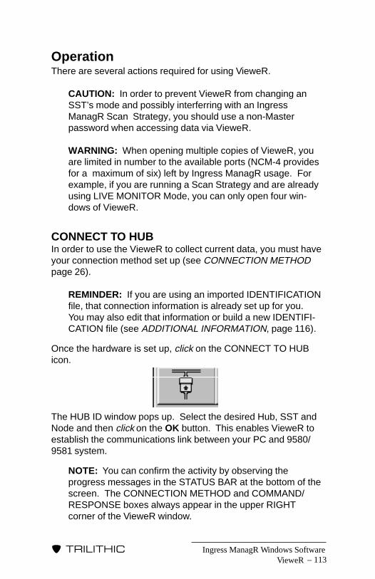
Ingress ManagR Windows Software – 113
�����������
VieweR
OperationThere are several actions required for using VieweR.
CAUTION: In order to prevent VieweR from changing anSST’s mode and possibly interferring with an IngressManagR Scan Strategy, you should use a non-Masterpassword when accessing data via VieweR.
WARNING: When opening multiple copies of VieweR, youare limited in number to the available ports (NCM-4 providesfor a maximum of six) left by Ingress ManagR usage. Forexample, if you are running a Scan Strategy and are alreadyusing LIVE MONITOR Mode, you can only open four win-dows of VieweR.
CONNECT TO HUBIn order to use the VieweR to collect current data, you must haveyour connection method set up (see CONNECTION METHODpage 26).
REMINDER: If you are using an imported IDENTIFICATIONfile, that connection information is already set up for you.You may also edit that information or build a new IDENTIFI-CATION file (see ADDITIONAL INFORMATION, page 116).
Once the hardware is set up, click on the CONNECT TO HUBicon.
The HUB ID window pops up. Select the desired Hub, SST andNode and then click on the OK button. This enables VieweR toestablish the communications link between your PC and 9580/9581 system.
NOTE: You can confirm the activity by observing theprogress messages in the STATUS BAR at the bottom of thescreen. The CONNECTION METHOD and COMMAND/RESPONSE boxes always appear in the upper RIGHTcorner of the VieweR window.

Ingress ManagR Windows Software114 –
�����������
VieweR
HUB DATA SPECIFICSOnce you have connected to the Hub, you can select the specificdata you wish to collect using the buttons at the bottom of thescreen.
The buttons include:
Hub – Selects the active Hub from list.
SST – Selects the active SST from list. Use the > buttonto go to the next SST in the current Hub.
Node – Selects the active Node from list. Use the > buttonto go to the next Node in the current SST.
NOTE: When cycling through the available hubs, SSTs andnodes, VieweR will attempt to maintain it’s connection. Thiscan be a problem if it encounters a hub, SST or node that isnot being used but is not labelled as such. Encounteringthese non-existent components will cause error messagesand will cause the VieweR to be disconnected. To make surethat VieweR cycles through the available componentscorrectly, make sure to rename such components as “UN-USED”. This way, VieweR will simply pass on to the nextcomponent.
Mode – Selects the desired mode: sweep, ingress(normal), fast, or zoom (if fast and zoom areallowed under the FAST MODE button.
NOTE: If you’re connected to an NCM-4 butare not the Master, you will NOT be able tochange the mode.
Limits – Use to hide or display the current limits for theselected Node. Use the “draw first” and “drawlast” setting to bring the desired trace forward.

Ingress ManagR Windows Software – 115
�����������
Max – Displays the peak value of ingress. This isuseful for capturing and holding the peak valueof infrequent/intermittent signals (FAST MODEingress data already supplies peak valuesunless the detector method is AVERAGE).
Fast Mode – Disables the FAST MODE feature. When itdisplays “NOT ALLOWED”, FAST MODE andZOOM Mode will not show as a setting underthe MODE button.
Detector – Changes the detector method (Traffic, Peak,Average).
Rate/RBW – Changes the FAST Mode node sample/resolu-tion bandwidth (20Hz/375kHz, 80Hz/525kHz).
To select a button, simply click on it. There is a delay before theaction is taken. This allows multiple mode changes or selectionsto be made; thus avoiding unnecessary mode switching andundesired data gathering.
NOTE: While viewing the data, you may print it any timeduring the scan by clicking on the PRINT icon.
You may also change mode, SST, Node and unit at any timewhile you are monitoring the data.
NOTE: The information box displays the data for the Hub,SST and Node which are being viewed.
PRINT DATAWhile you are monitoring the data, you can print any trace thatyou see as it happens. Click on the PRINT icon.
Your print out depends on what parameters you selected for thescan.
VieweR

Ingress ManagR Windows Software116 –
�����������
If you selected the MAX icon, the print out will contain the STARTand STOP times which were used to accumulate the peakreadings of the trace.
NOTE: The STOP time is always the moment that youclick on the PRINT icon.
MESSAGE DISPLAYThe right corner has a display area where messages may bedisplayed during the scan.
The possible messages are:
• Connecting – This message is displayed while VieweR isestablishing a connection and interrogating the SST abouits features and setup.
• Sweep Off-Line – When the SST is selected to be in FASTMode, field pieces (SSR, RSVP, RSVPII) cannot sweep.
• TPX In Use (NCM-4) – When a Master User locks a TPXon a bank, ALL other banks are frozen to the old data untilthe Master User logs off the NCM-4.
DISCONNECT THE HUBWhen you have finished scanning or printing, you need to closethe link. Click on the DISCONNECT FROM HUB icon.
The STATUS BAR should indicate that VieweR has disconnectedsuccessfully and shut down.
Additional InformationYou may also use the LOCAL and EXTERNAL commands in theSETUP Menu to generate the identification file for VieweR if youdo not wish to import an identification file from Ingress ManagR.
VieweR
Ingress ManagR Windows Software – 117
�����������
LOCAL SELECTIONYou may use VieweR’s LOCAL setup selection to build a newidentification file if you do not wish to use any parameters from anIngress ManagR identification file.
When you select this command, VieweR displays an IDENTIFI-CATION form which includes the IDENTIFIER, COMMUNICA-TION and ALARM LEVEL tabs. Set these up the same way youset the tabs in Ingress ManagR (see IDENTIFIER TAB page 37,COMMUNICATION TAB page 40, and ALARM LEVEL TAB page42).
EXTERNAL SELECTIONIf you wish to use an existing identification file, you may eitherimport the file (see SETUP on page 109) or select the EXTER-NAL command. The main difference is that if you use theEXTERNAL selection, it does not overwrite the LOCAL identifica-tion file. This means that you will not be able to edit or update theidentification information in the file.
VieweR

Ingress ManagR Windows Software118 –
�����������
VieweR
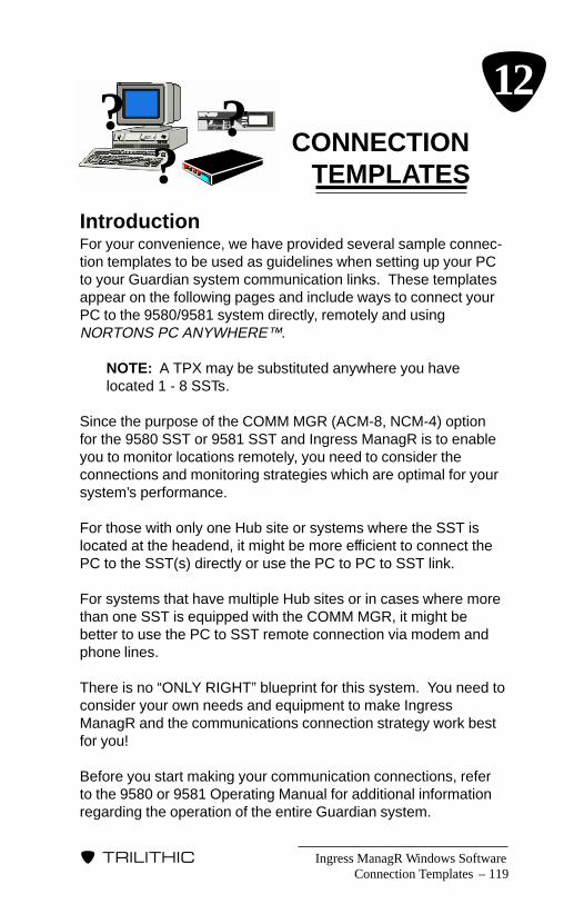
Ingress ManagR Windows Software – 119
�����������
CONNECTIONTEMPLATES
IntroductionFor your convenience, we have provided several sample connec-tion templates to be used as guidelines when setting up your PCto your Guardian system communication links. These templatesappear on the following pages and include ways to connect yourPC to the 9580/9581 system directly, remotely and usingNORTONS PC ANYWHERE™.
NOTE: A TPX may be substituted anywhere you havelocated 1 - 8 SSTs.
Since the purpose of the COMM MGR (ACM-8, NCM-4) optionfor the 9580 SST or 9581 SST and Ingress ManagR is to enableyou to monitor locations remotely, you need to consider theconnections and monitoring strategies which are optimal for yoursystem’s performance.
For those with only one Hub site or systems where the SST islocated at the headend, it might be more efficient to connect thePC to the SST(s) directly or use the PC to PC to SST link.
For systems that have multiple Hub sites or in cases where morethan one SST is equipped with the COMM MGR, it might bebetter to use the PC to SST remote connection via modem andphone lines.
There is no “ONLY RIGHT” blueprint for this system. You need toconsider your own needs and equipment to make IngressManagR and the communications connection strategy work bestfor you!
Before you start making your communication connections, referto the 9580 or 9581 Operating Manual for additional informationregarding the operation of the entire Guardian system.
Connection Templates
??? �12
Ingress ManagR Windows Software120 –
�����������
Using Nortons PC AnywhereNORTONS PC ANYWHERE software for Windows (version 2.0)enables you to control 1 PC remotely from another.
NOTE: Both PC’s need to be running Windows ‘95 or higher.
The first thing that you must do is follow the INSTALLATIONprocedure which came with NORTONS PC ANYWHERE. Youwill need to install the software on both the REMOTE PC (the PCthat you are using such as your home or laptop PC) and theHOST PC (the PC that will be running Ingress ManagR).
Next, verify that the REMOTE and HOST PCs are communicat-ing properly with each other.
CAUTION: It is imperative to be familiar with the COM Portsand Modem Ports on your equipment. For example, yourmouse usually takes COM Port 1 while your modem ormodems take additional ports. NORTONS PC ANYWHERErequires a COM Port of its own and will not share that COMPort with any other software or device.
For more information or help with setting up the linkupbetween the REMOTE and HOST PCs, refer to the manualwhich came with NORTONS PC ANYWHERE. This manualhas an extensive Communications Port Spectrum which willhelp you a great deal in setting up your system. You mayalso dial up Symantec’s demo HOST PC for help in trouble-shooting your setup.
Once the PCs communications linkup is working correctly, verifythat Ingress ManagR is running on the HOST PC and communi-cating with the 9580/9581 system.
REMINDER: You should test NORTONS PC ANYWHEREsoftware and Ingress ManagR separately as it will be easierto pinpoint problems than if you were trying to test everythingall at once.
Connection Templates

Ingress ManagR Windows Software – 121
�����������
The great thing about NORTONS PC ANYWHERE is that youcan set it up to run in the background on the HOST PC wheneverthat PC is ON.
Whenever you need to contact the HOST PC, you can connect toit via modem from your REMOTE PC. Once you have gainedcontrol of the HOST PC, start up Ingress ManagR and begin yourmonitoring session.
Connection Templates

Ingress ManagR Windows Software122 –
�����������
PC to SST(s) Remotely Via Modems
STEPS:1. Install Ingress ManagR software on PC.
2. Install 9580/9581 SST at Headend or Hub with the Communi-cations Manager option installed.
3. Connect satellite SSTs to the primary SST via standard 9-pinmale to 9-pin female RS-232 cables.
NOTE: When using the 9580 SST, you can connect up to7 satellite 9580 SSTs. When using the 9581 SST, you canconnect up to 3 satellite 9581 SSTs.
4. Using your PC and Ingress ManagR, configure your externalREMOTE modem.
5. Connnect the external REMOTE modem to the primarySST’s COMM MGR OUTPUT connection via a standardMODEM TO PC cable.
6. Connect a phone line to the LOCAL and REMOTE modemsand you are ready to go!
PC runningIngress Manager
Internal or ExternalLOCAL Modem External REMOTE
Modem
PrimarySSTw/CM option
56K minimum 56K minimum
Phone Line
(AT WORK STATION) (AT HEADEND OR HUB)
Connection Templates
SatelliteSSTs
NOTE: All SSTs are atthe same location
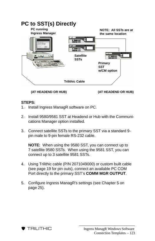
Ingress ManagR Windows Software – 123
�����������
PC to SST(s) Directly
STEPS:1. Install Ingress ManagR software on PC.
2. Install 9580/9581 SST at Headend or Hub with the Communi-cations Manager option installed.
3. Connect satellite SSTs to the primary SST via a standard 9-pin male to 9-pin female RS-232 cable.
NOTE: When using the 9580 SST, you can connect up to7 satellite 9580 SSTs. When using the 9581 SST, you canconnect up to 3 satellite 9581 SSTs.
4. Using Trilithic cable (P/N 2071049000) or custom built cable(see page 19 for pin outs), connect an available PC COMPort directly to the primary SST’s COMM MGR OUTPUT.
5. Configure Ingress ManagR’s settings (see Chapter 5 onpage 25).
Connection Templates
PC runningIngress Manager
PrimarySSTw/CM option
Trilithic Cable
(AT HEADEND OR HUB) (AT HEADEND OR HUB)
SatelliteSSTs
NOTE: All SSTs are atthe same location
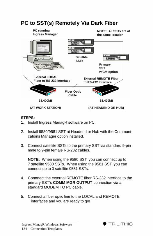
Ingress ManagR Windows Software124 –
�����������
PC to SST(s) Remotely Via Dark Fiber
STEPS:1. Install Ingress ManagR software on PC.
2. Install 9580/9581 SST at Headend or Hub with the Communi-cations Manager option installed.
3. Connect satellite SSTs to the primary SST via standard 9-pinmale to 9-pin female RS-232 cables.
NOTE: When using the 9580 SST, you can connect up to7 satellite 9580 SSTs. When using the 9581 SST, you canconnect up to 3 satellite 9581 SSTs.
4. Connnect the external REMOTE fiber RS-232 interface to theprimary SST’s COMM MGR OUTPUT connection via astandard MODEM TO PC cable.
5. Connect a fiber optic line to the LOCAL and REMOTEinterfaces and you are ready to go!
PC runningIngress Manager
External LOCALFiber to RS-232 Interface
External REMOTE Fiberto RS-232 Interface
PrimarySSTw/CM option
38,400kB 38,400kB
Fiber Optic Cable
(AT WORK STATION) (AT HEADEND OR HUB)
SatelliteSSTs
NOTE: All SSTs are atthe same location
Connection Templates
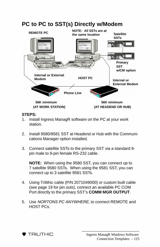
Ingress ManagR Windows Software – 125
�����������
PC to PC to SST(s) Directly w/Modem
STEPS:1. Install Ingress ManagR software on the PC at your work
station.
2. Install 9580/9581 SST at Headend or Hub with the Communi-cations Manager option installed.
3. Connect satellite SSTs to the primary SST via a standard 9-pin male to 9-pin female RS-232 cable.
NOTE: When using the 9580 SST, you can connect up to7 satellite 9580 SSTs. When using the 9581 SST, you canconnect up to 3 satellite 9581 SSTs.
4. Using Trilithic cable (P/N 2071049000) or custom built cable(see page 19 for pin outs), connect an available PC COMPort directly to the primary SST’s COMM MGR OUTPUT.
5. Use NORTONS PC ANYWHERE, to connect REMOTE andHOST PCs.
Connection Templates
REMOTE PC
Internal or ExternalModem Internal or
External Modem
PrimarySSTw/CM option
56K minimum 56K minimum
Phone Line
(AT WORK STATION) (AT HEADEND OR HUB)
SatelliteSSTs
HOST PC
NOTE: All SSTs are atthe same location
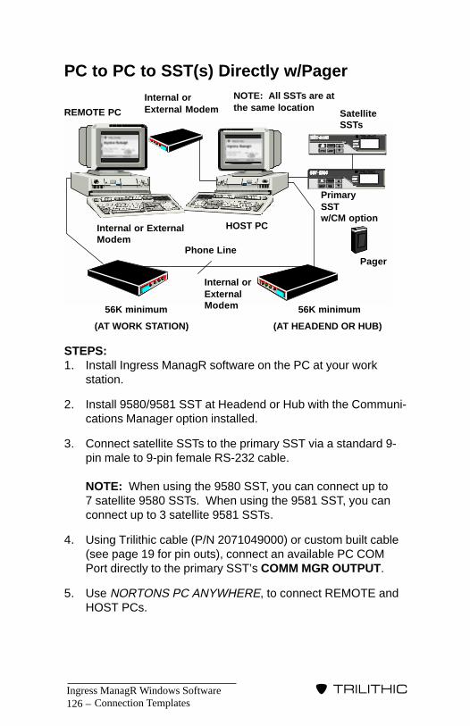
Ingress ManagR Windows Software126 –
�����������
PC to PC to SST(s) Directly w/Pager
STEPS:1. Install Ingress ManagR software on the PC at your work
station.
2. Install 9580/9581 SST at Headend or Hub with the Communi-cations Manager option installed.
3. Connect satellite SSTs to the primary SST via a standard 9-pin male to 9-pin female RS-232 cable.
NOTE: When using the 9580 SST, you can connect up to7 satellite 9580 SSTs. When using the 9581 SST, you canconnect up to 3 satellite 9581 SSTs.
4. Using Trilithic cable (P/N 2071049000) or custom built cable(see page 19 for pin outs), connect an available PC COMPort directly to the primary SST’s COMM MGR OUTPUT.
5. Use NORTONS PC ANYWHERE, to connect REMOTE andHOST PCs.
REMOTE PC
Internal or ExternalModem
Internal orExternalModem
PrimarySSTw/CM option
Phone Line
(AT WORK STATION) (AT HEADEND OR HUB)
SatelliteSSTs
HOST PC
NOTE: All SSTs are atthe same location
Connection Templates
Internal orExternal Modem
Pager
56K minimum 56K minimum

Ingress ManagR Windows Software – 127
�����������
PC to PC to SST(s) Remotely
NOTE: This setup requires NORTONS PC ANYWHERE.
STEPS:1. Install Ingress ManagR software on the PC at your work
station.
2. Install 9580/9581 SST at Headend or Hub with the Communi-cations Manager option installed.
3. Connect satellite SSTs to the primary SST via a standard 9-pin male to 9-pin female RS-232 cable.
NOTE: When using the 9580 SST, you can connect up to7 satellite 9580 SSTs. When using the 9581 SST, you canconnect up to 3 satellite 9581 SSTs.
4. Using your PC and Ingress ManagR, configure your externalremote modem.
5. Connnect the external REMOTE modem to the primarySST’s COMM MGR OUTPUT connection via a standardMODEM TO PC cable.
6. Connect a phone line to the LOCAL and REMOTE modemsand you are ready to go!
Connection Templates
REMOTEPC
Internal or ExternalModem
Internal orExternalModem
PrimarySSTw/CM option
Phone Line
(AT WORK STATION) (AT HEADEND OR HUB)
SatelliteSSTs
HOST PC
NOTE: All SSTs are atthe same location
Internal or ExternalLocal Modem
ExternalRemote Modem
56K minimum 56K minimum
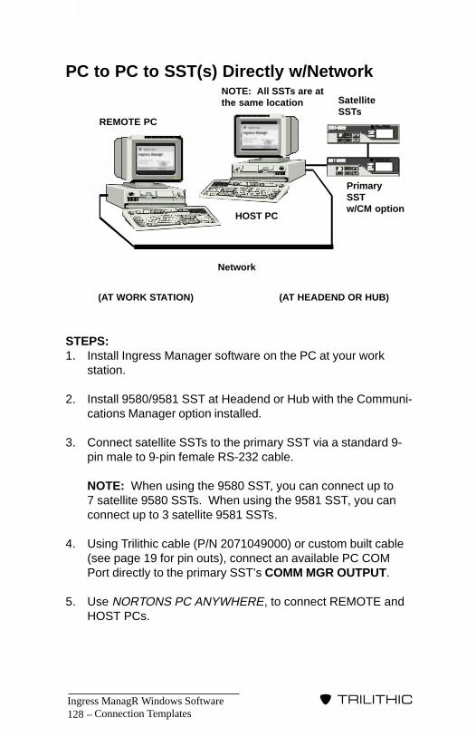
Ingress ManagR Windows Software128 –
�����������
PC to PC to SST(s) Directly w/Network
STEPS:1. Install Ingress Manager software on the PC at your work
station.
2. Install 9580/9581 SST at Headend or Hub with the Communi-cations Manager option installed.
3. Connect satellite SSTs to the primary SST via a standard 9-pin male to 9-pin female RS-232 cable.
NOTE: When using the 9580 SST, you can connect up to7 satellite 9580 SSTs. When using the 9581 SST, you canconnect up to 3 satellite 9581 SSTs.
4. Using Trilithic cable (P/N 2071049000) or custom built cable(see page 19 for pin outs), connect an available PC COMPort directly to the primary SST’s COMM MGR OUTPUT.
5. Use NORTONS PC ANYWHERE, to connect REMOTE andHOST PCs.
Connection Templates
PrimarySSTw/CM option
Network
(AT WORK STATION) (AT HEADEND OR HUB)
SatelliteSSTs
HOST PC
NOTE: All SSTs are atthe same location
REMOTE PC
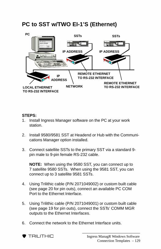
Ingress ManagR Windows Software – 129
�����������
PC to SST w/TWO EI-1’S (Ethernet)
STEPS:1. Install Ingress Manager software on the PC at your work
station.
2. Install 9580/9581 SST at Headend or Hub with the Communi-cations Manager option installed.
3. Connect satellite SSTs to the primary SST via a standard 9-pin male to 9-pin female RS-232 cable.
NOTE: When using the 9580 SST, you can connect up to7 satellite 9580 SSTs. When using the 9581 SST, you canconnect up to 3 satellite 9581 SSTs.
4. Using Trilithic cable (P/N 2071049002) or custom built cable(see page 20 for pin outs), connect an available PC COMPort to the Ethernet Interface.
5. Using Trilithic cable (P/N 2071049001) or custom built cable(see page 19 for pin outs), connect the SSTs’ COMM MGRoutputs to the Ethernet Interfaces.
6. Connect the network to the Ethernet Interface units.
Connection Templates
PC SSTs SSTs
REMOTE ETHERNETTO RS-232 INTERFACE
REMOTE ETHERNETTO RS-232 INTERFACE
IP ADDRESS IP ADDRESS
IPADDRESS
LOCAL ETHERNETTO RS-232 INTERFACE
NETWORK
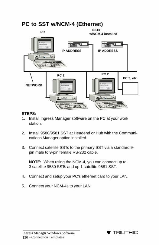
Ingress ManagR Windows Software130 –
�����������
Connection Templates
PC to SST w/NCM-4 (Ethernet)
STEPS:1. Install Ingress Manager software on the PC at your work
station.
2. Install 9580/9581 SST at Headend or Hub with the Communi-cations Manager option installed.
3. Connect satellite SSTs to the primary SST via a standard 9-pin male to 9-pin female RS-232 cable.
NOTE: When using the NCM-4, you can connect up to3 satellite 9580 SSTs and up 1 satellite 9581 SST.
4. Connect and setup your PC’s ethernet card to your LAN.
5. Connect your NCM-4s to your LAN.
PC SSTsw/NCM-4 installed
IP ADDRESS IP ADDRESS
NETWORK
PC 2 PC 2PC 3, etc.

Ingress ManagR Windows Software – 131
�����������
PC to SST w/EI-1 (Ethernet)
STEPS:1. Install Ingress Manager software on the PC at your work
station.
2. Install 9580/9581 SST at Headend or Hub with the Communi-cations Manager option installed.
3. Connect satellite SSTs to the primary SST via a standard 9-pin male to 9-pin female RS-232 cable.
NOTE: When using the 9580 SST, you can connect up to7 satellite 9580 SSTs. When using the 9581 SST, you canconnect up to 3 satellite 9581 SSTs.
4. Connect and setup your PC’s ethernet card to your LAN.
5. Using Trilithic cable (P/N 2071049001) or custom built cable(see page 19 for pin outs), connect the SSTs’ COMM MGRoutputs to the Ethernet Interfaces.
6. Connect the network to the Ethernet Interface units.
Connection Templates
PC
SSTs SSTs
REMOTE ETHERNETTO RS-232 INTERFACE
REMOTE ETHERNETTO RS-232 INTERFACE
IP ADDRESSIP ADDRESS
NETWORK
IP ADDRESS

Ingress ManagR Windows Software132 –
�����������
Connection Templates

Ingress ManagR Windows Software – 133
�����������
Sample Files
IntroductionFor your convenience, we have provided several sample files onthe Ingress ManagR installation disk. These files are designed tohelp you become more familiar with Ingress ManagR as well asto give you ideas as to how to use this versatile software.
Sample Scan StrategiesTo access the sample scan strategies, go to the SETUP Menuand select Scan Strategy (see SCAN STRATEGY page 70).Once you are in the SCAN STRATEGY screen, go to the FILEMenu and select OPEN to bring up the list of scan strategy filesin the IM30 folder..
Scan strategy files have an extension of .SGY such assample1.sgy.
SAMPLEFILES
�13

Ingress ManagR Windows Software134 –
�����������
SAMPLE1.SGYClick on SAMPLE1.SGY to open the first sample scan strategy.
REMINDER: You can adjust the strategy viewing window bysetting the cursor at the bottom or side of the screen. Whenthe cursor changes to a double arrow, adjust the window tothe desired shape and dimension.
Step Icon Action 1 Check Alarm activates alarm 2 Log All to Disk logs data to HUBLOG.MDB file 3 Scan Hub scans Hub #1 (Clover) 4 Scan Hub scans Hub #2 (Elwood) 5 Wait For waits one hour before next step 6 Goto Step repeats actions from Step 3
This Scan Strategy activates alarms and logs all data to disk fileHUBLOG.MDB. It scans Hubs “Clover” and “Elwood”, waits foran hour and then repeats. Sample Strategy 1 does NOT takedata every hour because it does not account for the time to pollHubs 1 and 2. If you want to take data every hour, you need toeither reduce the wait time or use the “If...Break” icon.
Sample Files
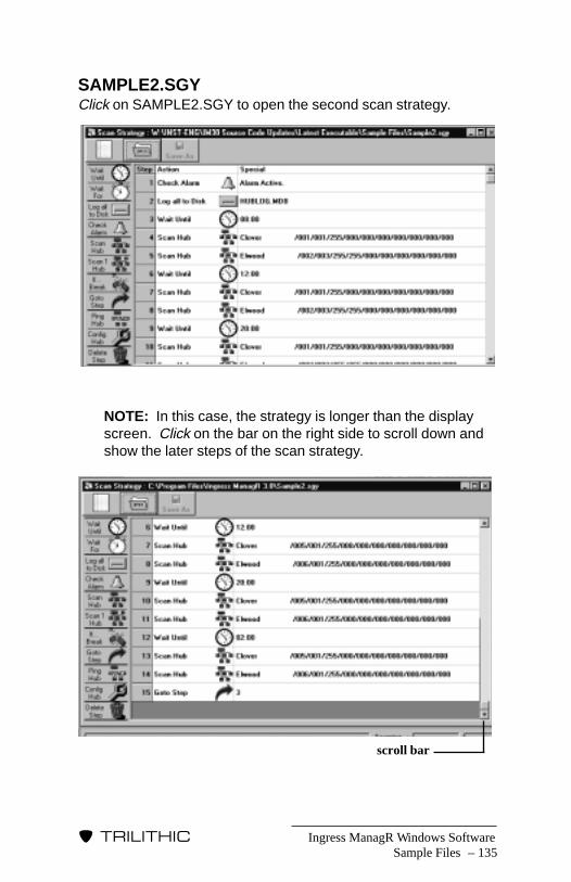
Ingress ManagR Windows Software – 135
�����������
SAMPLE2.SGYClick on SAMPLE2.SGY to open the second scan strategy.
NOTE: In this case, the strategy is longer than the displayscreen. Click on the bar on the right side to scroll down andshow the later steps of the scan strategy.
Sample Files
scroll bar
Ingress ManagR Windows Software136 –
�����������
Scan Strategy 2 (Continued)
Step Icon Action 1 Check Alarm activates alarm 2 Log All to Disk logs data to HUBLOG.MDB file 3 Wait Until waits until 8:00 in the morning
to begin (if strategy is startedafter 08:00, it waits until thefollowing morning to start).
4 Scan Hub scans Hub #1 (Clover) 5 Scan Hub scans Hub #2 (Elwood) 6 Wait Until waits until 12:00 noon 7 Scan Hub scans Hub #1 (Clover) 8 Scan Hub scans Hub #2 (Elwood) 9 Wait Until waits until 20:00 evening10 Scan Hub scans Hub #1 (Clover)11 Scan Hub scans Hub #2 (Elwood)12 Wait Until waits until 02:00 morning13 Scan Hub scans Hub #1 (Clover)14 Scan Hub scans Hub #2 (Elwood)15 Goto Step repeats actions from Step 3
This Scan Strategy illustrates how you can use a simple repetitivescan throughout the course of a twenty four hour period. Itactivates alarms and logs all data to disk file HUBLOG.MDB. Itwaits until eight in the morning and then scans Hubs “Clover” and“Elwood” once. It waits until twelve noon, and then scans the twoHubs once. It repeats the single scan of the Hubs at eight in theevening, two in the morning and then starts the entire sequenceagain at eight in the morning.
REMINDER: Ingress ManagR uses a twenty four hourclock. For example, eight at night should be programmedas 20:00 for 2000 hours.
Sample Files
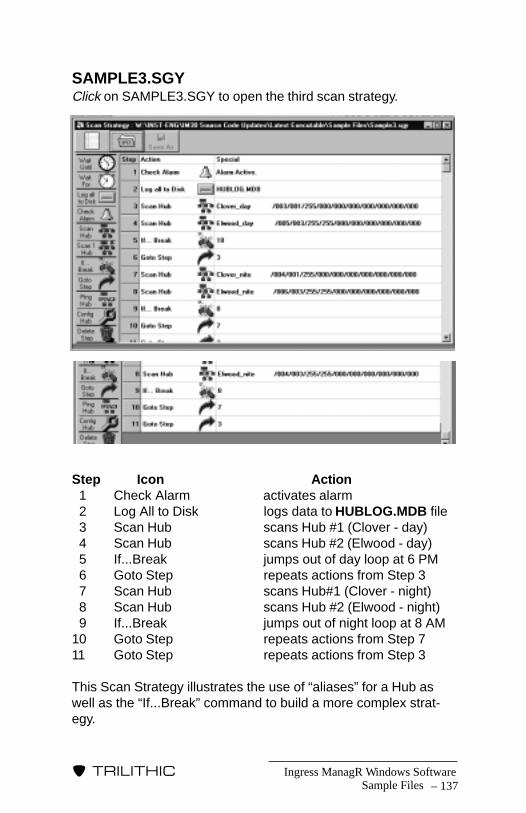
Ingress ManagR Windows Software – 137
�����������
SAMPLE3.SGYClick on SAMPLE3.SGY to open the third scan strategy.
Step Icon Action 1 Check Alarm activates alarm 2 Log All to Disk logs data to HUBLOG.MDB file 3 Scan Hub scans Hub #1 (Clover - day) 4 Scan Hub scans Hub #2 (Elwood - day) 5 If...Break jumps out of day loop at 6 PM 6 Goto Step repeats actions from Step 3 7 Scan Hub scans Hub#1 (Clover - night) 8 Scan Hub scans Hub #2 (Elwood - night) 9 If...Break jumps out of night loop at 8 AM10 Goto Step repeats actions from Step 711 Goto Step repeats actions from Step 3
This Scan Strategy illustrates the use of “aliases” for a Hub aswell as the “If...Break” command to build a more complex strat-egy.
Sample Files
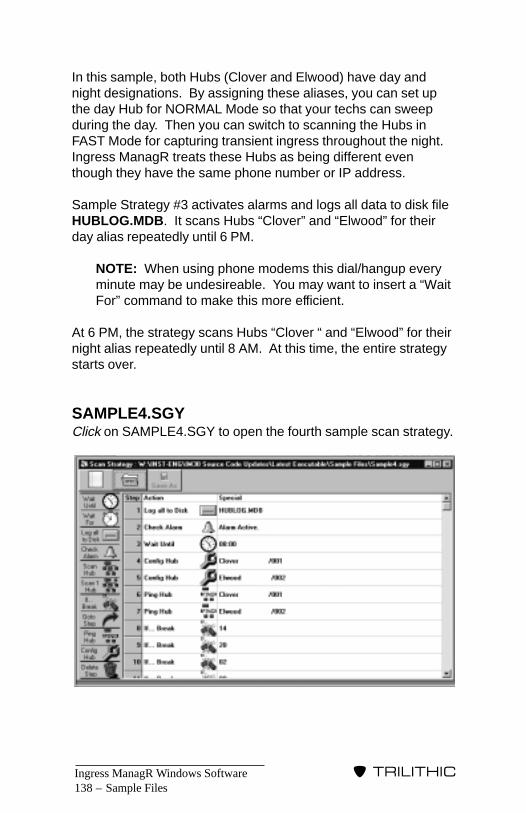
Ingress ManagR Windows Software138 –
�����������
Sample Files
In this sample, both Hubs (Clover and Elwood) have day andnight designations. By assigning these aliases, you can set upthe day Hub for NORMAL Mode so that your techs can sweepduring the day. Then you can switch to scanning the Hubs inFAST Mode for capturing transient ingress throughout the night.Ingress ManagR treats these Hubs as being different eventhough they have the same phone number or IP address.
Sample Strategy #3 activates alarms and logs all data to disk fileHUBLOG.MDB. It scans Hubs “Clover” and “Elwood” for theirday alias repeatedly until 6 PM.
NOTE: When using phone modems this dial/hangup everyminute may be undesireable. You may want to insert a “WaitFor” command to make this more efficient.
At 6 PM, the strategy scans Hubs “Clover “ and “Elwood” for theirnight alias repeatedly until 8 AM. At this time, the entire strategystarts over.
SAMPLE4.SGYClick on SAMPLE4.SGY to open the fourth sample scan strategy.

Ingress ManagR Windows Software – 139
�����������
Sample Strategy #4 continued.
Step Icon Action 1 Log All to Disk logs data to HUBLOG.MDB file 2 Check Alarm activates alarm 3 Wait Until waits until 8:00 in the morning
to begin (if strategy is startedafter 08:00, it waits until thefollowing morning to start).
4 Config Hub configures Hub #1 (Clover) 5 Config Hub configures Hub #2 (Elwood) 6 Ping Hub Pings Hub #1 (Clover) 7 Ping Hub Pings Hub #2 (Elwood) 8 If...Break jumps out of ping loop at 2 PM 9 If...Break jumps out of ping loop at 8 PM10 If...Break jumps out of ping loop at 2 AM11 If...Break jumps out of ping loop at 8 AM12 Goto Step repeats actions from Step 613 Scan Hub scans Hub #1 (Clover)14 Scan Hub scans Hub #2 (Elwood)15 Goto Step repeats actions from Step 6
Scan Strategy #4 illustrates the use of the PING command tominimize the time between checking for ingress outbreaks ateach Hub in combination with regularly scheduled poll commandsfor collecting performance data (remember, ping commands onlysave alarm data). This is done via a single ingress scan fourtimes a day to capture an ingress spectrum. This ensures thatsome data is captured for each Node in the system even thoughno Nodes may be experiencing ingress above limits.
Sample Files

Ingress ManagR Windows Software140 –
�����������
This strategy logs all data to disk file HUBLOG.MDB and acti-vates alarms. Starting at 8 AM, it configures the ACM-8s orNCM-4s just to be sure that the COMM MGRs are configuredwith the lastest information. The strategy pings both Hubs(Clover and Elwood) rapidly until 2 PM. Then, it takes an ingressscan of every Node and logs the data to disk. It returns topinging until 8 PM when it takes another ingress scan of everyNode and logs the data to disk. It continues pinging the Hubsuntil 2 AM and repeats the ingress scan and data logging proce-dure. It returns to pinging until 8 AM. Then it takes an ingressscan, logs the data to disk and starts over from the beginning.
NOTE: The “Wait Until” command MUST be encounteredprior to the “Wait Until” time specified for it to execute. If thelast “Goto Step” command had been to Step 3 (WAIT UNTIL8 AM), the strategy would pause for twenty four hours sincethe “If...Break” command takes place at or after 8 AM.
SAMPLE5.SGYClick on SAMPLE5.SGY to open the fifth sample scan strategy.
Sample Files
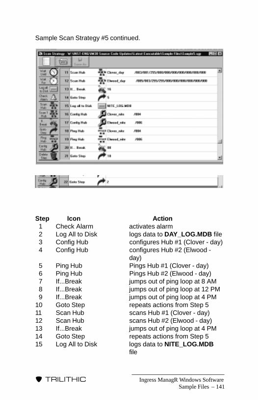
Ingress ManagR Windows Software – 141
�����������
Sample Scan Strategy #5 continued.
Step Icon Action 1 Check Alarm activates alarm 2 Log All to Disk logs data to DAY_LOG.MDB file 3 Config Hub configures Hub #1 (Clover - day) 4 Config Hub configures Hub #2 (Elwood -
day) 5 Ping Hub Pings Hub #1 (Clover - day) 6 Ping Hub Pings Hub #2 (Elwood - day) 7 If...Break jumps out of ping loop at 8 AM 8 If...Break jumps out of ping loop at 12 PM 9 If...Break jumps out of ping loop at 4 PM10 Goto Step repeats actions from Step 511 Scan Hub scans Hub #1 (Clover - day)12 Scan Hub scans Hub #2 (Elwood - day)13 If...Break jumps out of ping loop at 4 PM14 Goto Step repeats actions from Step 515 Log All to Disk logs data to NITE_LOG.MDB
file
Sample Files

Ingress ManagR Windows Software142 –
�����������
Sample Scan Strategy #5 continued.
Step Icon Action16 Config Hub configures Hub #1 (Clover -
night)17 Config Hub configures Hub #2 (Elwood -
night)18 Ping Hub Pings Hub #1 (Clover - night)19 Ping Hub Pings Hub #2 (Elwood - night)20 If...Break jumps out of ping loop at 8 AM21 Goto Step repeats actions from Step 1822 Goto Step repeats actions from Step 2*
*If the strategy returned to Step 3 (Config Hub), it would putall of its data into the NITE_LOG.MDB file. By returning toStep 2, you ensure that the data is logged into theDAY_LOG.MDB file.
Sample Scan Strategy #5 illustrates the use of a variety ofcommands to build a complex strategy that enables you to assignaliases to the Hubs so that you can collect different ingress datathrougout a twenty four hour period. With this strategy, you firstassign an alias for day and one for night for the two Hubs (Cloverand Elwood). As in Sample Scan Strategy #3, you can set up theday Hubs for NORMAL Mode so that your techs can sweepduring the day. Set up the night Hubs for FAST Mode so that youcan capture transients. You can also alternate the PING andSCAN Modes as well. This complex strategy should give you avery detailed overview of your Hubs’ ingress situation throughoutthe course of a day.
This strategy activates alarms and logs all of the data from the“day” aliases of the Hubs to disk in a file called DAY_LOG.MDB.It then configures the ACM-8s or NCM-4s to ensure that theCOMM MGRs are configured with the latest information. Thestrategy pings both Hubs (Clover and Elwood) rapidly until 8 AM.Then, it takes an ingress scan of every Node and logs the data todisk.
It returns to pinging until 12 PM when it takes another ingressscan and logs the data to disk. It repeats this pinging and ingressscan process until 4 PM.
Sample Files
Ingress ManagR Windows Software – 143
�����������
Sample Files
At 4 PM, the strategy scans both Hubs. It then switches to the“night” aliases where it logs all of the data from the “night” aliasesof the Hubs to disk in a file called NITE_LOG.MDB. It configuresthe ACM-8s and then pings both Hubs throughout the night until 8AM.
Final CommentThe samples included here show only a fraction of possibilitiesfor using Ingress Manager to monitor your 9580/9581 system.Now that you are more familiar with the software, feel free toexperiment and create your own sample files. Just rememberthat your Scan Strategies need to end in the .SGY extension.

Ingress ManagR Windows Software144 –
�����������
Sample Files

Ingress ManagR Windows Software – 145
�����������
MISCELLANEOUSINFORMATION
�14
IntroductionThis section contains additional material including connection andinterface information, driver boxes and the EVENT LOG.
Connection InformationIf you are using a modem, Ethernet Interface or Dark Fiber toconnect multiple SSTs, you may need additional information.This section provides you with some data concerning hardwaresetups of modems and interface units that you will need to doprior to connecting them to your SST system. You should alsorefer to the documentation which came with the device.
MODEM DIP SWITCH SETTINGAlthough, Ingress ManagR is delivered with default Hayescommands for several modem models, it may still be necessaryto set the DIP switches on the modem in order to optimize yourcommunication set up.
There are eight DIP switches on a USR Sportster modem whichshould be set to the following configuration.
NOTE: Most modems will have the DIP switch values listedsomewhere on the unit and/or in its manual. The tablesbelow are based on the US Robotics Sportster Model.Please use the position for the appropriate applicationsince the location of the switches on your modem may differ.
?
Miscellaneous Information
?

Ingress ManagR Windows Software146 –
�����������
Remote ModemSWITCH APPLICATION POSITIONSW 1 Data Terminal Ready Overide DownSW 2 Verbal Result Codes UpSW 3 Suppress Result Codes UpSW 4 Echo Offline Commands UpSW 5 Auto Answer on 1st Ring UpSW 6 Carrier Detect Overide DownSW 7 Load NVRAM Defaults UpSW 8 Smart Mode Down
Local ModemSWITCH APPLICATION POSITIONSW 1 Data Terminal Ready Normal UpSW 2 Verbal Result Codes UpSW 3 Display Result Codes DownSW 4 Echo Offline Commands UpSW 5 Audio Answer Off DownSW 6 Carrier Detect Normal UpSW 7 Load NVRAM Defaults UpSW 8 Smart Mode Down
NOTE: The above are the USR factory default positions.
ETHERNET INTERFACE INFORMATIONThe EI-1 Ethernet Interface unit enables your 9580/9581 systemto make use of your existing network (10 Base-T Ethernet) whichconnects hubs, headends and offices. By using the interface unitto connect to the network, you will no longer need phone lines toconnect each location.
The EI-1 Ethernet and FI-1 Fiber Interfaces are easy to use.
For the EI-1 Ethernet Interface, you must first set the IPAddresses on the units and then connect the host interface unitto your PC and the remote interface(s) to your 9580/9581 SSTunit(s). Refer to the CONNECTION TEMPLATES on pages 129and 131 for guidelines for connecting the devices together.
Miscellaneous Information

Ingress ManagR Windows Software – 147
�����������
Miscellaneous Information
You must also select NETWORK for the communication methodon the COMMUNICATION tab (see COMMUNICATION TABpage 40).
NOTE: When you select NETWORK for the communicationmethod, the button next to the PHONE #/IP ADDRESS boxindicates the port to which the interface is connected.
For more information on configuring and installing the interfaceunits, refer to the EI-1 ETHERNET INTERFACE/FI-1 FIBERINTERFACE INSTALLATION GUIDE which came with theinterface unit.
FIBER INTERFACE INFORMATIONThe FI-1 Fiber Interface unit enables your 9580/9581 system toutilize unused or “dark” fibers in your system so that you candirect connect remote SST units without needing to use a modemand phone lines.
It is easy to connect the FI-1 Fiber Interface. Just hook it up andyou’re ready to go. See the CONNECTION TEMPLATE on page114 for guidelines for connecting your 9580/9581 system via theFI-1 Fiber Interface.
For more information on configuring and installing the interfaceunits, refer to the EI-1 ETHERNET INTERFACE/FI-1 FIBERINTERFACE INSTALLATION GUIDE which came with theinterface unit.
NCM-4 INTERFACE INFORMATIONThe NCM-4 is a high speed, Communications Manager whichprovides multi-user access to your 9580/9581 SST Return PathAnalyzer. The NCM-4 is an Ethernet-compatible interface. It canobtain ingress data simultaneously from up to four SST units andstores a fresh ingress spectrum for each of the 32 nodes approxi-mately every three fourths of a second. The interface then actsas a server by making this data available via standard communi-cations manager comands.

Ingress ManagR Windows Software148 –
�����������
The NCM-4 emulates the ACM-8 Communications Manager inlocal limits checking and support of the PING function (for moreinformation, see PING METHOD page 50). Due to its servertopology, the NCM-4 enables you to view LIVE data for any nodewithout stopping or interrupting a running scan strategy.
TCP/IP SetupRegardless of which version of the Windows operating systemyou are using, you must have TCP/IP installed on your PC.
TCP/IP INSTALLATIONIt is important to note that your computer may have two networkadapters. This could occur if you use a modem to connect to theinternet, as well as a network card. In this case, each installedprotocol can be associated to either network adapter, or both ofthem. When following the instructions below, you should makesure you have TCP/IP associated with the network adapter youplan to use with Ingress ManagR.
1. To begin your installation, click on the Start button. Fromthere, go to SETTINGS and then CONTROL PANEL.
2. Next, double-click on the NETWORK Icon.
3. Check to see if TCP/IP is listed as one of the protocols. If itis, you have TCP/IP installed already. Skip to Step 15.
4. If TCP/IP is not on the list, click Add....
5. Now, click PROTOCOL. Click Add... again.
6. Next, click on MICROSOFT in the left display, click on TCP/IP in the right display. Click OK.
7. Once that is done, click OK in the Network Window. Win-dows will install TCP/IP on your computer.
8. When the installation is completed, Windows may tell you toreboot. Click NO. (We’ll reboot after some changes).
Miscellaneous Information
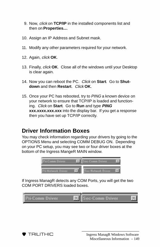
Ingress ManagR Windows Software – 149
�����������
9. Now, click on TCP/IP in the installed components list andthen on Properties....
10. Assign an IP Address and Subnet mask.
11. Modify any other parameters required for your network.
12. Again, click OK.
13. Finally, click OK. Close all of the windows until your Desktopis clear again.
14. Now you can reboot the PC. Click on Start. Go to Shut-down and then Restart. Click OK.
15. Once your PC has rebooted, try to PING a known device onyour network to ensure that TCP/IP is loaded and function-ing. Click on Start. Go to Run and type PINGxxx.xxxx.xxx.xxx into the display bar. If you get a responsethen you have set up TCP/IP correctly.
Driver Information BoxesYou may check information regarding your drivers by going to theOPTIONS Menu and selecting COMM DEBUG ON. Dependingon your PC setup, you may see two or four driver boxes at thebottom of the Ingress MangeR MAIN window.
If Ingress ManagR detects any COM Ports, you will get the twoCOM PORT DRIVERS loaded boxes.
Miscellaneous Information

Ingress ManagR Windows Software150 –
�����������
If Ingress ManagR detects an Ethernet card which has beeninstalled correctly, you will also get the two NETWORK DRIVERSloaded boxes.
NOTE: If the NETWORK DRIVERS do not load, closeIngress ManagR and recheck your Windows network setup(see TCP/IP SETUP on page 138) or check with your net-work department. Settings on the driver boxes are also usedfor factory assistance. These are not meant for user modifi-cation.
Event LogThe EVENT LOG box maintains a record of the messages whichappear in the STATUS BAR (see page 23).
To display the EVENT LOG box, go to the OPTIONS Menu andselect SHOW EVENT LOG. A minimized Event Log window willappear in the lower part of the Main Screen. Double-click on it toexpand the window.
You can use the EVENT LOG feature several ways:
• Log Errors, Traps – select this setting to have IngressManagR log only the errors and traps it encounters (this isthe default setting).
Miscellaneous Information

Ingress ManagR Windows Software – 151
�����������
• Log All Events – select this setting to have IngressManagR log all of the messages and events which occurduring operation.
• Auto-Archive Log Files – select this setting to haveIngress ManagR log all of the messages and events to anarchive file (located in the EVENT LOG folder in IngressManagR’s directory, specified as Eventlog_date_time.txt.i.e. Eventlog_20010118_160710.txt).
When using the Log All Events or Log Errors, Traps settings,you may save or print the Event Log at any time by clicking on theSAVE and PRINT buttons. If you wish to clear the log, click onthe CLEAR button.
If you do not wish to use the EVENT LOG feature, simply go tothe OPTIONS Menu and de-select SHOW EVENT LOG.
Time SynchronizationDepending on the configuration of the PC and the softwarerunning within Windows, the Windows system clock may lagbehind the PC’s real time clock. This can effect the correlation ofdata with date/time stamps.
NOTE: The TIME SYNCHRONIZATION feature is used forWindows ‘98 or Windows Millenium Edition. This option isnot available for Windows NT or Windows 2000 and will bebe “grayed” out.
To synchronize the time, go to the OPTIONS Menu at the MAINwindow and select TIME SYNC TO LOCAL RTC.
Miscellaneous Information

Ingress ManagR Windows Software152 –
�����������
Miscellaneous Information

���������������� ���
9202 E. 33rd St.Indianapolis, IN 46236
(317) 895-3600
P/N 0010205000 2/01 Made in U.S.A.
�����������