sst configure software - viavisolutions.com · sst configure software - operation manual 2...
TRANSCRIPT

SST ConfigureSoftware
OPERATIONMANUAL

SST Configure Software - Operation Manual2
Trilithic Company ProfileTrilithic is a privately held manufacturer founded in 1986 as an engineering and assemblycompany that built and designed customer-directed products for telecommunications, military andindustrial customers. From its modest beginnings as a two-man engineering team, Trilithic grewover the years and broadened its offerings of RF and microwave components by addingbroadband solutions to its product line. This was accomplished with the acquisition ofcomponents manufacturer Cir-Q-Tel and instruments manufacturer Texscan.
Today, Trilithic is an industry leader providing telecommunications solutions for major broadband,RF and microwave markets around the world. As an ISO 9000:2001 certified company with over40 years of collective expertise in engineering and custom assembly, Trilithic is dedicated toproviding quality products, services and communications solutions that exceed customerexpectations.
Trilithic is comprised of three major divisions:
• Broadband Instruments & SystemsOffers test, analysis and quality management solutions for the major cable televisionsystems worldwide.
• RF Microwave ComponentsProvides components and custom subsystems for companies specializing in cellular,military and other wireless applications.
• Emergency Alert SystemsLeading supplier of government-mandated emergency alert systems used by HFC serviceproviders.

SST Configure Software - Operation Manual3
1. General Information ..............................................................................................................4Helpful Website ..................................................................................................................... 4Where to Get Technical Support ............................................................................................. 4How this Manual is Organized ................................................................................................5Conventions Used in this Manual ........................................................................................... 5
2. Introduction...........................................................................................................................6What is the SST Configure Software? ....................................................................................6Overview of the SST Configure Software ............................................................................... 6Remote Operation .................................................................................................................7Upgrading Your 9581 RSA to a 9581 SST .............................................................................7
3. Installation ............................................................................................................................. 8Overview ...............................................................................................................................8Minimum PC Hardware Requirements ...................................................................................8Installing the SST Configure Software ....................................................................................8
4. Configuration ...................................................................................................................... 11Overview ............................................................................................................................. 11Initial Configuration .............................................................................................................. 11Advanced Configuration ......................................................................................................16
Connecting to the Instrument via Ethernet........................................................................16IP Configuration..............................................................................................................18ECM Configuration .........................................................................................................19SNMP Configuration ......................................................................................................25Security ..........................................................................................................................28Device Names ...............................................................................................................30Device Mode..................................................................................................................32Field Piece Detector ......................................................................................................34Link Frequencies............................................................................................................36Sweep Frequencies .......................................................................................................37Signal Settings ...............................................................................................................38
Bulk Send ............................................................................................................................40Sync Clock ..........................................................................................................................42Device Standby Mode..........................................................................................................42Save Device Settings ..........................................................................................................43Load Device Settings ..........................................................................................................44Work Offline .........................................................................................................................45
Table of Contents

SST Configure Software - Operation Manual4
1. General Information 1
Helpful WebsiteThe following website contains general information which may be of interest to you:
http://www.trilithic.com
Trilithic’s website contains product specifications and information, tips, release information,marketing information, Frequently Asked Questions (FAQs), bulletins and other technicalinformation. You can also check this website for product updates.
Where to Get Technical SupportTrilithic technical support is available Monday through Friday from 8:00AM to 5:00PM EST.Callers in North America can dial 1-317-895-3600 or 1-800-344-2412 (toll free). Internationalcallers should dial 1-317-895-3600 or fax questions to 1-317-895-3613. You can also e-mailtechnical support at [email protected].
For quicker support response when calling or sending e-mail, please provide the followinginformation:
• Your name and your company name
• The technical point of contact (name, phone number, e-mail)
• The software version numbers
• A detailed description of the problem you are having, including any error or informationmessages

SST Configure Software - Operation Manual5
How this Manual is OrganizedThis manual is divided into the following chapters:
• Chapter 1, “General Information” provides Trilithic contact information and describes howthis Operation Manual is structured.
• Chapter 2, “Introduction” introduces what the SST Configure Software is and what it does.
• Chapter 3, “Installation” describes the steps needed to install the SST Configure Software.
• Chapter 4, “Configuration” describes the steps needed to perform the configuration of the9581 SST R4 and 9581 RSA.
Conventions Used in this ManualThis manual has several standard conventions for presenting information.
• Connections, Menus, menu options, and user entered text and commands appear in bold.
• Section names, Web and email addresses appear in italics.
Note: A note is information that will be of assistance to you related tothe current step or procedure.
WARNING: A warning alerts you to any condition that could causepersonal injury.
CAUTION: A caution alerts you to any condition that could cause amechanical failure or potential loss of data.
SST Configure Software - Operation Manual6
2. Introduction 2
Note: Depending on user privileges, the user profile of interest may ormay not be able to be modified.
What is the SST Configure Software?SST Configure is the setup and administration software for the 9581 SST R4 Return PathAnalyzer and the 9581 RSA Return SpeedSweep Analyzer. This software is easy to use andencompasses a range of functions that allow you to take full advantage of the features of thesedevices and also simplify their operation.
Some of the features that can be administered using SST Configure include:
• User account settings
• Device settings
• IP connectivity
• Alarm monitoring parameters
In addition, this software allows the uploading and storage of the settings from one device andthen download them into other devices.
Overview of the SST Configure SoftwareThe SST Configure software can perform the following tasks:
• Configure the device’s settingsBecause the 9581 SST R4 and 9581 RSA are not configurable as a stand-alone units,the SST Configure software must be used to set forward telemetry carriers, reversesweep carriers, etc. These settings can be stored locally on the PC, which is useful if theuser organization has several devices and wants to create and maintain standardconfigurations for all of them.
• Administer user accounts for devicesUse SST Configure to upload and download account information for the 32 users thatcan be stored in your instrument. Additions, modifications and deletions to maintainaccess security for these user accounts are done through SST Configure.
• Administer alarm criteria for devicesAlarm criteria determine the conditions, frequency of alarm and types of alarms issued.Alarm criteria can be uploaded and downloaded to your instrument with SST Configure.

SST Configure Software - Operation Manual7
• Administer SNMP configuration (with purchased SNMP option)A SNMP configuration can be uploaded and downloaded to the 9581 SST R4. Thisconfiguration affects how Traps are generated and to which destinations they will be sentas well as which version of the SNMP protocol will be used. Also, access rights to the MIBcan be defined and placed in the 9581 SST R4 according to user security needs.
Remote OperationThis software is intended to be operated remotely. Remote operation will most likely only beuseful to a system administrator or high-end user making system level decisions. Directconnection should only be necessary during initial installation of your instrument or duringreconfiguration of any routers in the connectivity path.
The most efficient method of installation is:
1. IT personnel should modify any necessary router settings.
2. The system installer can then connect directly long enough to establish IT connectivity usingthe IP Config tab.
3. A more in depth setup can then be applied remotely to finish the installation.
For further assistance, contact Trilithic technical support. Technical support is available Mondaythrough Friday from 8:00AM to 5:00PM EST. International callers should dial 1-317-895-3600 orfax questions to 1-317-895-3613. You can also e-mail technical support [email protected].
Upgrading Your 9581 RSA to a 9581 SSTA 9581 RSA can be upgraded to the functionality of the 9581 SST by pressing the UpdateDevice to an SST button that appears when connected to a 9581 RSA. To upgrade your9581 RSA, contact Trilithic Sales. Trilithic Sales is available Monday through Friday from 8:00AMto 5:00PM EST. International callers should dial 1-317-895-3600 or toll free in North America1-888-895-7630. You can also e-mail sales at [email protected].

SST Configure Software - Operation Manual8
OverviewThis chapter covers the minimum software requirements of the PC that you wish to install the SSTConfigure software on as well as how to install the SST Configure software on your PC.
Minimum PC Hardware RequirementsTo operate the SST Configure software, the PC that the software is to be installed on MUST meetthe following minimum requirements:
• Pentium III class processor
• 64 MB RAM
• 100 MB free disk space
• Windows 2000® or XP
• Color monitor running at 256 colors or higher, 1024x768 screen resolution
• Windows compatible mouse
• DB-9 straight through serial data cable or Ethernet connection with access to the9581 SST R4 or 9581 RSA
Installing the SST Configure SoftwareOnce the PC meets the minimum requirements, the SST Configure software is ready to install.
3. Installation 3
Note: Depending on the operating system used, logging on as thelocal administrator to install SST Configure may be needed. If thecurrent login account permissions are not known, check with the networkor systems administrator.
1. Insert the SST Configure installation CD into the CD-ROM drive.
Note: Be sure to check the CD for release notes that may affect theinstallation and configuration process!

SST Configure Software - Operation Manual9
2. If Autorun is enabled for the CD-ROM drive, the SST Configure setup program will startautomatically.
OR
2. If Autorun is not enabled for the CD-ROMdrive, follow the instructions below to start theinstallation process.
• Select the Start button (which is found on thelower left-hand of your screen).
• Select Run... from menu.
• Type D:\SST_Setup.exe (substitute theappropriate drive path if D is not your CD-ROM drive).
• Select the OK button.
3. Once all other programs are closed, select theNext> button from the window that appears.
4. Select the Destination folder from the followingwindow. Select the Next> button to use the defaultinstallation directory or select the Browse buttonto change the installation directory.

SST Configure Software - Operation Manual10
5. To proceed with the installation, select the Next>button from the window that appears or select the<Back button to go back to the previousinstallation screen.
6. During installation the following window willappear indicating status of the installation.
7. After installation is complete the following windowwill appear, select the Close button to exit theinstallation.

SST Configure Software - Operation Manual11
4. Configuration 4
Note: The first time configuration of your instrument must be completedusing the serial port because the instrument does not initially know howto connect itself through an ethernet connection. This information will bemanually entered as part of this initial configuration.
OverviewIn this chapter we will discuss how to perform initial and advanced configuration of your9581 SST R4 and 9581 RSA.
The following information will be needed before your instrument can be configured:
• Static IP address for each SST or RSA
• Subnet Mask for each SST or RSA
• Gateway IP address for each SST or RSA
• Static IP address for Viewer II software
• Target IP address for each client to the SST
• How many users will need access and their user names and passwords
• Hub names
• Node names
Initial ConfigurationBefore setting parameters or sending information to/from your instrument, the instrument must beconnected to the PC:
1. Connect the device’s Port-1 or Port-2 to the PC’s serial port using a straight through serialcable.
2. Start the SST Configure software.
SST Configure Software - Operation Manual12
3. Make sure that the Use Ethernet check boxis not selected.
4. Enter the PC’s com port value in the ComPort box.
5. Select the Connect to SST/Set Optionsbutton.
6. The SST Login window will appear, enter theappropriate User Name and Password asfollows:
• New user, by default the instrumenthas only one account where both UserName and Password are admin.Enter the default User Name andPassword.
• Returning user, type in theappropriate User Name andPassword.
7. When finished, select the OK button. It maytake up to 30 seconds for the next screen toappear.

SST Configure Software - Operation Manual13
Note: It is very important that all information on the IP Config tab iscorrect. Once updates have been downloaded into the instrument and areboot has been performed, if the IP information is wrong ethernetcommunication will not be able to be established with the instrument. Ifthis happens, go back to the instrument, reconnect to it with a regularserial cable, update the information, perform another download andreboot.
8. The Options window will appear with the IP Config tab selected.
Per your network requirements, enter your instrument’s:
• IP Address
• Subnet Mask
• Gateway IP Address
• Primary and secondary DNS Addresses
If you don’t know your DNS Addresses, defaults will be placed on the form by theinstrument.
9. When finished, select the OK button.

SST Configure Software - Operation Manual14
10.Select the Send Options to SST button.
11. The SST Login window will appear, enter theappropriate User Name and Password.After entering the User Name andPassword, select the OK button to continue.

SST Configure Software - Operation Manual15
Note: If you receive an error message, try rebooting again. If thatdoesn’t work, contact your network administrator and make sure the IPsettings you entered are correct. If your IP settings are correct, contactTrilithic technical support.
12.When prompted, select the OK button toput the new IP configurations into effectand automatically reboot at the sametime.

SST Configure Software - Operation Manual16
Note: Trilithic recommends using an ethernet connection because boththe upload and download speeds will increase dramatically. An ethernetconnection is roughly ten times faster than a connection using a serialcable.
Advanced ConfigurationThis section covers the advanced configuration process for your instrument. If configuring onlyspecific features of the device, go directly to those sections. See the Table of Contents for exactlocations of each feature configuration.
Connecting to the Instrument via Ethernet1. Complete the initial configuration of your instrument as shown in the previous section.
2. Disconnect the serial cable from your instrument and connect the instrument to a PC usingan ethernet connection.
3. Make sure that the Use Ethernet check boxis selected.
4. Enter the instrument’s IP address in the IPaddress of SST box. (This value is equal tothe IP address entered in the previoussection.)
5. Select the Connect to SST/Set Optionsbutton.
SST Configure Software - Operation Manual17
Note: Only select the OK button after completing setup of all advancedconfiguration options, otherwise Step 5 and Step 6 will need to becompleted again in order to re-enter the Connect to SST/Set Optionsfeature of the SST Configure software.
Note: Not all options tabs are displayed at one time. To display moreoptions tabs, use the right and left arrow keys to scroll through the tabs.
7. The Options window will open.
6. The SST Login window will appear, enter theappropriate User Name and Password.After entering the User Name andPassword, select the OK button to continue.

SST Configure Software - Operation Manual18
Note: To complete the configuration, select OK, then select the SendOptions to SST (select OK at login screen) button on the main screen,then select the OK button to reboot your instrument.
IP ConfigurationBy default the IP Config tab will appear when entering the Connect to SST/Set Options featureof the SST Configure software. Refer to Step 8 of the Initial Configuration Section for moreinformation on entering connection information for your instrument.
Note: To continue with the configuration of other advancedconfiguration options, proceed to the appropriate section.
Note: To load selected device settings from a saved definition file,select the Load Device Settings button, see the Load Device Settingssection in this chapter for more information.

SST Configure Software - Operation Manual19
Note: If the ECM option IS NOT activated, this section does not applyto your 9581 SST R4.
Note: Contact the Trilithic sales department to obtain an activationcode. Phone: 1-800-344-2412 (toll free in North America) or1-317-895-3600 E-mail: [email protected]
ECM Configuration
1. If the ECM option has been purchased and activated, choose the ECM Config tab andenable the ECM option by selecting the ECM Enabled checkbox.
Note: The ECM option is not available for the 9581 RSA. So, the ECMConfig tab will not appear when SST Configure is connected to a9581 RSA.

SST Configure Software - Operation Manual20
2. As part of the ECM configuration up to 8 user profiles can be created for which therewill be threshold curves. To setup a user profile;
• To create a new profile, select the Profile Name: box and type in a uniqueprofile name and press the ENTER key.
• To rename an existing profile, select the down arrow next to the Profile Name:dropdown box to pick an existing profile, then change the profile name and thenselect the Change Name button.
• Choose the correct SNMP Trap Version from the TRAP Settings heading. Ifsending traps to Viewer II, select 1. For more information on how to setup Traps,see the Traps Setup Section of this chapter.
• Choose the correct Alarm/TRAP Mode selection. For more information on howto setup Alarms, see the Alarm Setup Section of this chapter.
• Select the Compressions active on this profile checkbox if this particularuser profile is to be used to store long-term compressed ingress data.
Note: To load selected device settings from a saved definition file,select the Load Device Settings button, see the Load Device Settingssection in this chapter for more information.
Note: To continue with the configuration of other advancedconfiguration options, proceed to the appropriate section.
Note: To complete the configuration, select OK, then select the SendOptions to SST (select OK at login screen) button on the main screen,then select the OK button to reboot your instrument.

SST Configure Software - Operation Manual21
Alarm SetupTo create alarm curves for this profile, select the Set Up Alarms button. The alarm criteriawill be used to generate ingress threshold violation alarms.
1. The Profile Alarm Settings heading will automatically be filled in by theinstrument. Modify the values if needed.
• For Ingress Mode, Viewer II users MUST select the Standard checkboxfrom the Ingress Mode heading.
• Ingress ManagR users can select the MIN Hold or MAX Hold checkboxfrom the Ingress Mode heading in combination with ping mode scanstrategies.
6

SST Configure Software - Operation Manual22
2. Select the SST A or SST B checkbox from the SST Side heading. The 16inputs to the instrument are grouped as 8 inputs for SST A and 8 inputs forSST B.
3. Select the appropriate node from the Node Selected: drop-down list. Thecurrent trace and alarm threshold curve levels will appear in the large blackdisplay window.
4. Modify an alarm threshold curve level by selecting the appropriate level from theThreshold Modification Tools heading. To set the desired start/stopfrequencies of an alarm threshold curve;
• Select the alarm threshold curve with the mouse and physically move it
OR
• Enter the values manually in the Start:, Stop:, and Level: boxes from theKeyboard Entry Method heading.
OR
• Model an alarm threshold curve after an existing curve by entering a valuein the offset in dB box from the Curve Copy w/ offset heading.
5. Select the Modify Threshold button. The alarm threshold curve will change thenext time the screen updates.
6. To undo the last changes made to a threshold curve, select the Undo button.
7. To disable a node’s alarms, select the node of interest as shown in Step 3 andthen select the Disable Node checkbox.
8. To copy the alarm threshold curves of one node to additional nodes of the sameinstrument perform the following steps;
• Select the Copy Curves button from the Cloning Tools heading.
• Select a new node as shown in Step 3.
• Select the Apply to this Node button.
9. To copy the alarm threshold curves of one node to an entire side of the sameinstrument perform the following steps;
• Select the Copy Curves button from the Cloning Tools heading.
• Select a new node as shown in Step 3.
• Select the Apply to all nodes this side button.

SST Configure Software - Operation Manual23
10.To copy the alarm threshold curves of one node to all nodes on all profilesperform the following steps;
• Select the Copy Curves button from the Cloning Tools heading.
• Select the Apply to all nodes on all profiles button.
• When prompted, select the YES button to apply to all nodes on allprofiles, select the NO button to cancel.
11. To select different views of the ingress signal select either the Freeze Ingress,Peak Hold Graph, or Min Hold Graph checkbox.
12.When finished making changes to the alarm setup, select the OK button.
Note: The traffic threshold curve cannot be copied to other nodes orprofiles because it is SST side specific and NOT node specific.
CAUTION: Adjusting any one node’s Traffic threshold changes allnodes on that side.

SST Configure Software - Operation Manual24
1. Choose the trap number by selecting the up or down arrow next to the TrapNumber box.
2. Enter an address in the Destination IP/DNS Name: box.
3. Choose the community name by selecting the up or down arrow next to theCommunity Name: box.
4. Select the applicable checkboxes from the TRAP types heading.
5. When finished making changes to the TRAP setup, select the OK button.
Trap SetupIf the SNMP option has been purchased and activated, select the correct profile from theECM Config tab and select the Set Up TRAP’s button. If this option has not beenactivated, the Set Up TRAP’s button does not appear and this section does not apply toyour 9581 SST R4.
SST Configure Software - Operation Manual25
SNMP Configuration
1. If the SNMP option has been purchased and activated, choose the SNMP Config taband enable the SNMP option by selecting the SNMP Enabled checkbox. The SNMPEnabled checkbox does not appear and the option cannot be enabled without firstenabling the ECM option.
Note: If the ECM or SNMP option IS NOT activated, this section doesnot apply to your 9581 SST R4.
Note: Contact the Trilithic sales department to obtain an activationcode. Phone: 1-800-344-2412 (toll free in North America) or1-317-895-3600 E-mail: [email protected]
Note: The SNMP option is not available for the 9581 RSA. So, theSNMP Config tab will not appear when SST Configure is connected toa 9581 RSA.

SST Configure Software - Operation Manual26
2. Under the Device Type heading, select whether this device will act as a SNMP masterunit or SNMP slave unit relative to the SNMP gets and sets from the MIB.
• For 9581 SST R4s that will have their own IP on the corporate LAN ratherthan being behind a router for IP conservation, select the Master checkboxand do not enter any slaves in the Device IP List.
• For 9581 SST R4s that are hidden behind a router in an IP conservationscheme using individual TCP ports for addressing, select the Mastercheckbox for one of the 9581 SST R4s to select it as SNMP master and selectthe Slave checkbox for all other 9581 SST R4s on that single IP address.
• For 9581 SST R4s configured as the SNMP master with slaves can haveup to 15 slaves on their slave list.
3. To enter an IP address in the Device IP List, type in the IP address of the 9581 SSTR4 and select the Add IP button.
4. To delete an IP address from the Device IP List, select the down arrow next to thedropdown list, select the appropriate IP address, and select the Delete IP button.
5. Under the System Information heading, enter the system information for this specific9581 SST R4.
• In the System Contact box, type in the name of the person serving as a systemcontact when a trap comes in.
• In the System Name box, type in the device name of the 9581 SST R4. Thisname can be the same as the Device Name on the Device Names tab, butdoes not have to be.
• In the System Location box, type in the device name of the 9581 SST R4. Thisname can be the same as the Hub Name on the Device Names tab, but doesnot have to be.
6. Under the SNMP Access Settings heading, setup the communications accesssettings as follows;
• Under the V1/2C Access Settings heading, setup at least one communityname in the Community Names: box. If you do not setup a community name,there will not be any SNMP destinations available.

SST Configure Software - Operation Manual27
a. To create a new community name in the Community Names dropdownlist, type in a unique community name and select the Add button.
b. To delete an existing community name from the Community Namesdropdown list, select the down arrow next to the dropdown list, select theappropriate community name, and select the Delete button.
c. To set access for a specific community, select the down arrow next to thedropdown list, select the appropriate community name, and select thecheckbox next to Set Access.
• Under the V3 Access Settings heading, setup the access, authentication, andencryption for a specific user by selecting the down arrow next to the dropdownlist, selecting the appropriate user name, and then perform the following actions;
a. To set access, select the checkbox next to Set Access.
b. To set the type of authentication, select the appropriate radio button underthe V3 Authentication heading.
c. To set the type of encryption, select the appropriate radio button under theV3 Privacy heading.
• Contact the local IT department for help with completing the items in the SNMPAccess Settings box.
Note: To continue with the configuration of other advancedconfiguration options, proceed to the appropriate section.
Note: To complete the configuration, select OK, then select the SendOptions to SST (select OK at login screen) button on the main screen,then select the OK button to reboot your instrument.
Note: To load selected device settings from a saved definition file,select the Load Device Settings button, see the Load Device Settingssection in this chapter for more information.

SST Configure Software - Operation Manual28
Note: In order to modify settings in the Security tab, the user must belogged in to the instrument as an administrator.
Security
1. Select the Security tab.
2. Up to 31 user names and passwords can be entered. To setup a new user account;select the UserName: box and type in a unique user name, select the Password: boxand type in a unique password, select the appropriate checkbox from the User ProfileModification Rights, and then select the Add User button.
3. To delete a user name:, select the appropriate user name by selecting the down arrownext to the UserName: dropdown box to pick an existing user name and select theDelete User button.
4. The user name and password of the administrator account can be edited by entering aunique user name and password in the UserName: and Password: boxes from theAdmin Settings heading.

SST Configure Software - Operation Manual29
Note: To continue with the configuration of other advancedconfiguration options, proceed to the appropriate section.
Note: To complete the configuration, select OK, then select the SendOptions to SST (select OK at login screen) button on the main screen,then select the OK button to reboot your instrument.
Note: To load selected device settings from a saved definition file,select the Load Device Settings button, see the Load Device Settingssection in this chapter for more information.

SST Configure Software - Operation Manual30
Device Names1. Select the Device Names tab.
2. Select the Hub Name: box and enter the hub name of that the 9581 SST R4 isphysically connected to and then press the ENTER key.
3. Select the Device Name: box and enter a unique device name for the 9581 SST R4.
Note: The device name must be unique because it will serve as anidentifier when an alarm trap is sent out.
4. To enter custom node names, select either the SST A Node Names or SST B NodeNames button. The SST A Node Names window is shown in the following figure.

SST Configure Software - Operation Manual31
5. Enter a unique node name for each node and then select the OK button.
Note: Each node name must be unique because it will serve as anidentifier when an alarm trap is sent out.
Note: To continue with the configuration of other advancedconfiguration options, proceed to the appropriate section.
Note: The Hub Name, Device Name, and Node Names entered will bethe same names seen by the Viewer II software that is part of theGuardian II System and will be sent as part of the SNMP trap content ifthat option has been enabled.
Note: To complete the configuration, select OK, then select the SendOptions to SST (select OK at login screen) button on the main screen,then select the OK button to reboot your instrument.

SST Configure Software - Operation Manual32
Device Mode
1. Select the Device Mode tab.
2. On this tab the ingress monitoring mode of the instrument will be selected. The followingchoices are available:
• Select the 40 Hz Ingress Monitoring (375KHz) with field piece sweepENABLED radio button to enable the reverse sweep and RSVP support.
• Select the 120 Hz Ingress Monitoring (375KHz) with field piece sweepDISABLED radio button to disable the reverse sweep and RSVP support.
Note: The Device Mode tab will not appear when SST Configure isconnected to a 9581 RSA, since the 9581 RSA can only operate in the40 Hz Ingress Monitoring (375KHz) with field piece sweepENABLED ingress monitoring mode.
Note: Either mode will supply 375 KHz RBW ingress monitoring at oneof the two rates and still supports ingress feedback to the field pieces.
Note: To load selected device settings from a saved definition file,select the Load Device Settings button, see the Load Device Settingssection in this chapter for more information.

SST Configure Software - Operation Manual33
Note: To continue with the configuration of other advancedconfiguration options, proceed to the appropriate section.
Note: To complete the configuration, select OK, then select the SendOptions to SST (select OK at login screen) button on the main screen,then select the OK button to reboot your instrument.

SST Configure Software - Operation Manual34
Field Piece Detector
1. Select the Field Piece Detector tab.
Note: The Field Piece Detector tab will not appear when SSTConfigure is connected to a 9581 RSA, since the 9581 RSA can onlyoperate in the Average Ingress mode.
2. On this tab the ingress detector mode that is sent to the field pieces will be determined.The following choices are available:
• Select the Peak Ingress radio button to send the peak of all ingress to the fieldpieces. This may be the preferred mode for users attempting to troubleshootingthe source of system ingress.
• Select the Average Ingress radio button to send the average of all ingress tothe field pieces. This may be the preferred mode for users supporting RSVPs inthe field where the best estimate of C/N ratio is required.
• Select the Traffic radio button to send the peak of all ingress below the trafficcurves that are defined to the field pieces. This may be the preferred mode forusers attempting to troubleshoot system ingress in the presence of activechannels or known system traffic.

SST Configure Software - Operation Manual35
Note: To continue with the configuration of other advancedconfiguration options, proceed to the appropriate section.
Note: To complete the configuration, select OK, then select the SendOptions to SST (select OK at login screen) button on the main screen,then select the OK button to reboot your instrument.
Note: To load selected device settings from a saved definition file,select the Load Device Settings button, see the Load Device Settingssection in this chapter for more information.

SST Configure Software - Operation Manual36
Link Frequencies1. Select the Link Freqs tab.
2. On this tab the link frequencies to be used in sending telemetry to the field pieces willbe entered.
• These frequencies can be the same if narrowcasting (only one telemetry carrierper forward feed) the telemetry signal.
• Where there are multiple telemetry signals carried on a common forward feed,the link frequencies should be separated by 500 KHz.
Note: To load selected device settings from a saved definition file,select the Load Device Settings button, see the Load Device Settingssection in this chapter for more information.
Note: To complete the configuration, select OK, then select the SendOptions to SST (select OK at login screen) button on the main screen,then select the OK button to reboot your instrument.
Note: To continue with the configuration of other advancedconfiguration options, proceed to the appropriate section.

SST Configure Software - Operation Manual37
Sweep Frequencies1. Select the Sweep Freqs tab.
2. On this tab the sweep frequencies used in conjunction with the telemetry to the fieldpieces will be entered.
• Select the appropriate checkbox below the 1st/Lst heading.
• Next to the corresponding checkbox, select the beginning and endingfrequencies for use in computing the gain and tilt measurements performed bythe 9581 SST R4.
Note: To load selected device settings from a saved definition file,select the Load Device Settings button, see the Load Device Settingssection in this chapter for more information.
Note: To continue with the configuration of other advancedconfiguration options, proceed to the appropriate section.
Note: To complete the configuration, select OK, then select the SendOptions to SST (select OK at login screen) button on the main screen,then select the OK button to reboot your instrument.
SST Configure Software - Operation Manual38
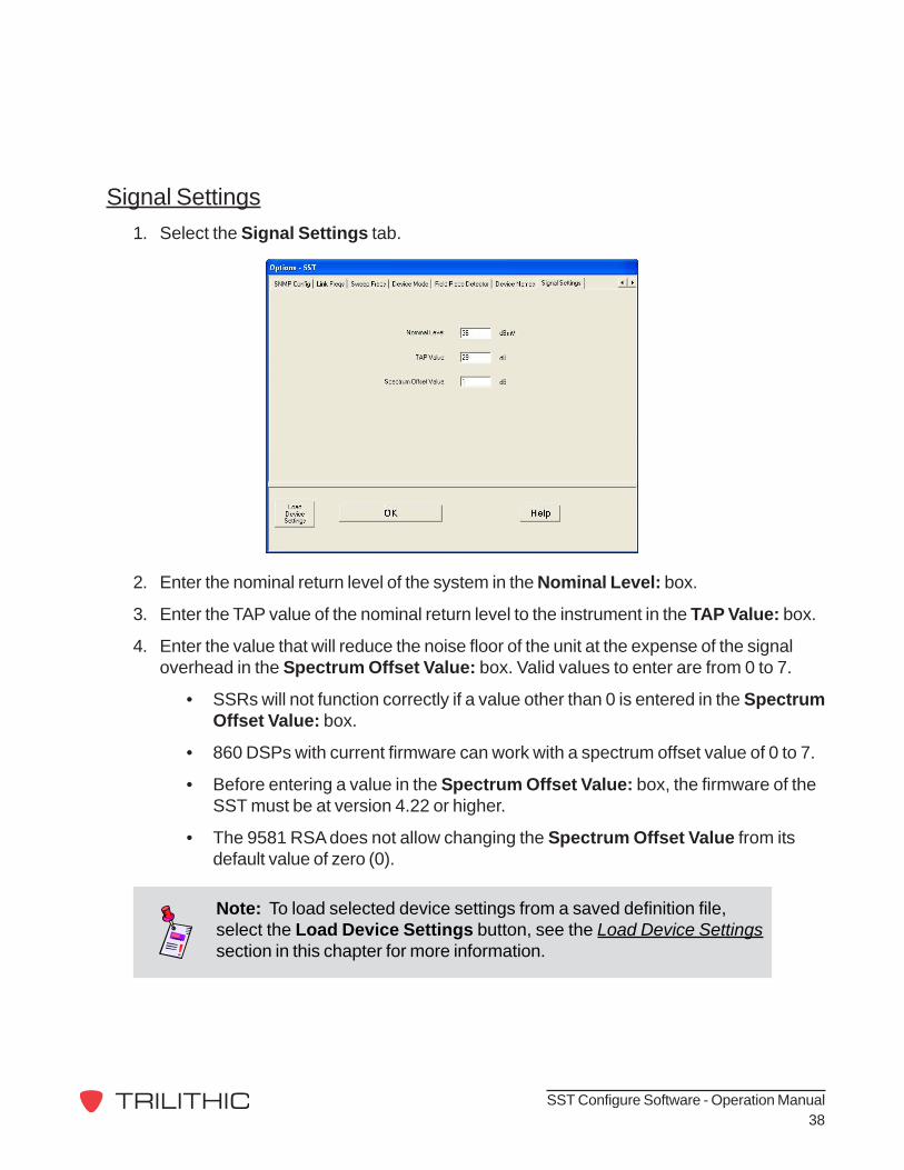
Signal Settings1. Select the Signal Settings tab.
2. Enter the nominal return level of the system in the Nominal Level: box.
3. Enter the TAP value of the nominal return level to the instrument in the TAP Value: box.
4. Enter the value that will reduce the noise floor of the unit at the expense of the signaloverhead in the Spectrum Offset Value: box. Valid values to enter are from 0 to 7.
• SSRs will not function correctly if a value other than 0 is entered in the SpectrumOffset Value: box.
• 860 DSPs with current firmware can work with a spectrum offset value of 0 to 7.
• Before entering a value in the Spectrum Offset Value: box, the firmware of theSST must be at version 4.22 or higher.
• The 9581 RSA does not allow changing the Spectrum Offset Value from itsdefault value of zero (0).
Note: To load selected device settings from a saved definition file,select the Load Device Settings button, see the Load Device Settingssection in this chapter for more information.

SST Configure Software - Operation Manual39
Note: To continue with the configuration of other advancedconfiguration options, proceed to the appropriate section.
Note: To complete the configuration, select OK, then select the SendOptions to SST (select OK at login screen) button on the main screen,then select the OK button to reboot your instrument.

SST Configure Software - Operation Manual40
Bulk SendUse the bulk send option to send a group of options to multiple instruments.
1. Select the Bulk Send... button.
2. Enter the IP addresses of the appropriateinstruments or select the Open IP ListFrom a File button to open a previouslysaved list file.
3. Select the checkbox next to theappropriate options to send to theinstruments or select the checkbox next toAll to send all options to theinstruments.
4. Enter the default login User Name andPassword.
5. Select the Send button.
Note: To save your IP list for future use, select the Save IP List to aFile button, select the correct path name, enter the IP list file name, andthen select the Save button.

SST Configure Software - Operation Manual41
6. The Bulk Send - SST Settings area willappear at the bottom of the main screen.This will show the progress of the bulkupdate on an instrument by instrumentbasis.
• The Skip This Device button isused to skip the device shown in theSending To Device at IP field.
• The Stop After This Device buttonis used to stop the bulk updateprocess after the current instrumentis updated.
7. As the bulk updates are completed or notcompleted for each IP address, the IPaddress will be shown in the DevicesComplete or Devices NOT Completedfields.
• To save a list of IP addresses thathave either had the bulk updatecompleted or not completed, selectthe corresponding Save to Filebutton.
• Select the correct path name, enterthe desired definition file name, andthen select the Save button.
8. After the bulk update has been complete, the Bulk Send - SST Settings area will display(Done), select the OK button to close this area of the main screen.

SST Configure Software - Operation Manual42
Sync ClockSelect the Sync Clock button to synchronize yourinstrument’s clock to the clock on your PC, enteryour user name and password, and then select theOK button.
Device Standby ModeSelect the Place Device in STANDBY button to putyour instrument into standby mode, enter your username and password, and then select the OK button.
To bring the instrument back from standby mode,select the Reboot Device button, enter your username and password, and then select the OK buttonto reboot your instrument.

SST Configure Software - Operation Manual43
Save Device SettingsSelect the Save Device Settings button to saveselected device settings to a definition file on yourPC, select the correct path name, enter the desireddefinition file name, and then select the Save button.
The Save Settings to File! window will appear.Select the desired device settings to save byselecting the corresponding check-box, and thenselect the OK button or select the Cancel button toexit without saving.

SST Configure Software - Operation Manual44
Load Device SettingsSelect the Load Device Settings button to loadselected device settings from a definition file on yourPC, select the correct path name, enter the desireddefinition file name, and then select the Openbutton.
The Load Settings from File! window will appear.Select the desired device settings to load byselecting the corresponding check-box, and thenselect the OK button or select the Cancel button toexit without loading.

SST Configure Software - Operation Manual45
Work OfflineSelect the Work Offline check-box to edit and savedevice settings without connecting to an instrument.Once you have selected this check-box, you canaccess the Options window by selecting theConnect to Device / Set Options button.

9710 Park Davis DriveIndianapolis, IN 46235
(317) 895-3600www.trilithic.com
P/N 0010236000 04/08 Made in U.S.A.