grundfos pt100 pt1000
TRANSCRIPT

grundfos INSTRUCTIONS
Pt100Pt1000

2 3
3Pt1000MS4”
1 2Pt1000MS4”
Pt100/1000 MS6”
Pt100/1000 MMS6”/8”
Pt100/1000 MMS10”
Pt100/1000 MMS12”

4 5
654Pt1000MS4”
Pt100/1000 MS6”
Pt100/1000 MMS6”/8”
Pt100/1000 MMS10”
Pt100/1000 MMS12”

6 7
1 3
4 218Nm
1 3
4 218Nm
1 3
4 218Nm
987Pt1000MS4”
Pt100/1000 MS6”
Pt100/1000 MMS6”/8”
Pt100/1000 MMS10”
Pt100/1000 MMS12”

8 9
1 3
4 250Nm
1 3
4 250Nm
1 3
4 250Nm
3Pt100/ 1000
MS6”
1 2Pt1000MS4”
Pt100/1000 MS6”
Pt100/1000 MMS6”/8”
Pt100/1000 MMS10”
Pt100/1000 MMS12”

10 11
7654Pt1000MS4”
Pt100/1000 MS6”
Pt100/1000 MMS6”/8”
Pt100/1000 MMS10”
Pt100/1000 MMS12”

12 13
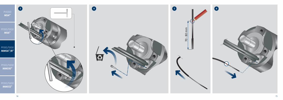
2Pt100/1000MMS 6”/8”
1Pt1000MS4”
Pt100/1000 MS6”
Pt100/1000 MMS6”/8”
Pt100/1000 MMS10”
Pt100/1000 MMS12”
14 15
43
70 -
80 m
m
65Pt1000MS4”
Pt100/1000 MS6”
Pt100/1000 MMS6”/8”
Pt100/1000 MMS10”
Pt100/1000 MMS12”

16 17
1 3
4 26” - 50Nm8” - 150Nm
45°
! 9
If there is a risk of sediment build-up, such as sand,
around the motor, a flow sleeve should be used in
order to ensure proper cooling of the motor.
* At an ambient pressure of minimum 1 bar (1 MPa)
5. Electrical connection
5.1 General
The electrical connection should be carried out by an
authorised electrician in accordance with local
regulations.
The supply voltage, rated maximum current and
cos � appear from the loose data plate that must be
fitted close to the installation site.
The required voltage quality for Grundfos MS and
MMS submersible motors, measured at the motor
terminals, is – 10 %/+ 6 % of the nominal voltage
during continuous operation (including variation in
the supply voltage and losses in cables).
Furthermore, it must be checked that there is voltage
symmetry in the electricity supply lines, i.e. same
difference of voltage between the individual phases.
See also 9. Checking of motor and cable, point 2.
If MS motors with a built-in temperature transmitter
(Tempcon) are not installed together with an MP 204
or similar Grundfos motor protection, they must be
connected to a 0.47 µF capacitor approved for
phase-phase operation (IEC 384-14) to meet the
EC EMC directive (2004/108/EC). The capacitor
must be connected to the two phases to which the
temperature transmitter is connected. See fig. 4.
Fig. 4Connection of capacitor
The motors are wound for direct-on-line starting or
star-delta starting and the starting current is between
4 and 6 times the rated current of the motor.
The run-up time of the motor is only about
0.1 second. Direct-on-line starting is therefore
normally approved by the electricity supply
authorities.
5.1.1 Frequency converter operation
Three-phase MS motors can be connected to a
frequency converter.
If a temperature transmitter is required, a Pt100
sensor for fitting to the submersible motor can be
ordered from Grundfos.
Note
In cases where the stated liquid
velocity cannot be achieved, a flow
sleeve must be installed.
Motor
Installation
Flow
past the
motor
VerticalHorizontal
MS 402
MS 4000
MS 6000
0.15 m/s40 °C
(~ 105 °F)
40 °C
(~ 105 °F)
MS 4000I*
MS 6000I*0.15 m/s
60 °C
(~ 140 °F)
Flow sleeve
recommended
60 °C
(~ 140 °F)
Flow sleeve
recommended
MS6T300.15 m/s
30 °C
(~ 86 °F)
30 °C
(~ 86 °F)
MS6T601.0 m/s
60 °C
(~ 140 °F)
60 °C
(~ 140 °F)
MMS
0.15 m/s25 °C
(~ 77 °F)
25 °C
(~ 77 °F)
0.50 m/s30 °C
(~ 86 °F)
30 °C
(~ 86 °F)
Note
For 37 kW MMS 6000, 110 kW MMS 8000
and 170 kW MMS 10000, the maximum
liquid temperature is 5 °C lower than
the values stated in the above table.
For 190 kW MMS 10000, the
temperature is 10 °C lower.
Warning
Before starting work on the motor,
make sure that the electricity supply
has been switched off and that it cannot
be accidentally switched on.
Warning
The motor must be earthed.
The motor must be connected to an
external mains switch with a minimum
contact gap of 3 mm in all poles.
TM00
710
0 06
96
Caution
If an MS motor with temperature
transmitter is connected to a frequency
converter, a fuse incorporated in the
transmitter will melt and the transmitter
will be inactive. The transmitter cannot
be reactivated. This means that the
motor will operate like a motor without
a temperature transmitter.
1 2 3 4
1 = L1: brown
2 = L2: black
3 = L3: grey
4 = PE: yellow/green
0.47 F
8
4.1.2 Grundfos MS6 and MS 6000 submersible
motors
• If the motor is delivered from stock, the liquid
level must be checked before the motor is
installed. See fig. 2.• In the case of service, the liquid level must be
checked. See fig. 2.Filling procedure:The filling hole for motor liquid is placed at the top of
the motor.
1. Position the submersible motor as shown in fig. 2.
The filling screw must be at the highest point of
the motor.2. Remove the screw from the filling hole.
3. Inject liquid into the motor with the filling syringe,
fig. 2, until the liquid runs back out of the filling
hole.
4. Replace the screw in the filling hole and tighten
securely before changing the position of the
motor.Torque: 3.0 Nm.The submersible motor is now ready for installation.
Fig. 2 Motor position during filling – MS6 and
MS 60004.1.3 Grundfos MMS 6000, MMS 8000, MMS 10000
and MMS 12000 submersible motors
Filling procedure:Place the motor at a 45 ° angle with the top of the
motor upwards. See fig. 3.5. Unscrew the plug (A) and place a funnel in the
hole.6. Pour tap water into the motor until the motor liquid
inside the motor starts running out at the plug (A).
Caution: Do not use motor liquid as it contains
oil.7. Remove the funnel and refit the plug (A).
The submersible motor is now ready for installation.
Fig. 3 Motor position during filling – MMS
4.2 Positional requirementsThe motor can be installed either vertically or
horizontally.A complete list of motor types suitable for horizontal
installation is shown in section 4.2.1.
4.2.1 Motors suitable for horizontal installation
4.3 Liquid temperatures/cooling
The maximum liquid temperature and the minimum
liquid velocity past the motor appear from the
following table.It is recommended to install the motor above the well
screen in order to achieve proper motor cooling.
TM
03 8
129
0507
CautionBefore fitting the motor to a pump after
a long period of storage, lubricate the
shaft seal by adding a few drops of
water and turning the shaft.
45°
TM
03
206
5 3
605
Motor typePower output 50 Hz Power output 60 Hz[kW]
[kW]
MS
All sizesAll sizes
MMS 60003.7 to 30
3.7 to 30
MMS 800022 to 92
22 to 92
MMS 1000075 to 170
75 to 170
MMS 12000147 to 220
–CautionDuring operation, the motor must
always be completely submerged in the
liquid. Please consult the pump
manufacturer's NPSH data.WarningIf the motor is used in hot liquids
(40 to 60 °C), it must be ensured that
persons cannot come into contact with
the motor and the installation, e.g. by
installing a guard.
45°
A
987Pt1000MS4”
Pt100/1000 MS6”
Pt100/1000 MMS6”/8”
Pt100/1000 MMS10”
Pt100/1000 MMS12”

18 19
2Pt100/1000
MMS10”
1Pt1000MS4”
Pt100/1000 MS6”
Pt100/1000 MMS6”/8”
Pt100/1000 MMS10”
Pt100/1000 MMS12”

20 21
3 mm
100mm
3 54Pt1000MS4”
Pt100/1000 MS6”
Pt100/1000 MMS6”/8”
Pt100/1000 MMS10”
Pt100/1000 MMS12”

22 23
1 3
4 2280Nm
45°
!9
If there is a risk of sediment build-up, such as sand,
around the motor, a flow sleeve should be used in
order to ensure proper cooling of the motor.
* At an ambient pressure of minimum 1 bar (1 MPa)
5. Electrical connection
5.1 General
The electrical connection should be carried out by an
authorised electrician in accordance with local
regulations.
The supply voltage, rated maximum current and
cos � appear from the loose data plate that must be
fitted close to the installation site.
The required voltage quality for Grundfos MS and
MMS submersible motors, measured at the motor
terminals, is – 10 %/+ 6 % of the nominal voltage
during continuous operation (including variation in
the supply voltage and losses in cables).
Furthermore, it must be checked that there is voltage
symmetry in the electricity supply lines, i.e. same
difference of voltage between the individual phases.
See also 9. Checking of motor and cable, point 2.
If MS motors with a built-in temperature transmitter
(Tempcon) are not installed together with an MP 204
or similar Grundfos motor protection, they must be
connected to a 0.47 µF capacitor approved for
phase-phase operation (IEC 384-14) to meet the
EC EMC directive (2004/108/EC). The capacitor
must be connected to the two phases to which the
temperature transmitter is connected. See fig. 4.
Fig. 4Connection of capacitor
The motors are wound for direct-on-line starting or
star-delta starting and the starting current is between
4 and 6 times the rated current of the motor.
The run-up time of the motor is only about
0.1 second. Direct-on-line starting is therefore
normally approved by the electricity supply
authorities.
5.1.1 Frequency converter operation
Three-phase MS motors can be connected to a
frequency converter.
If a temperature transmitter is required, a Pt100
sensor for fitting to the submersible motor can be
ordered from Grundfos.
Note
In cases where the stated liquid
velocity cannot be achieved, a flow
sleeve must be installed.
Motor
Installation
Flow
past the
motor
VerticalHorizontal
MS 402
MS 4000
MS 6000
0.15 m/s40 °C
(~ 105 °F)
40 °C
(~ 105 °F)
MS 4000I*
MS 6000I*0.15 m/s
60 °C
(~ 140 °F)
Flow sleeve
recommended
60 °C
(~ 140 °F)
Flow sleeve
recommended
MS6T300.15 m/s
30 °C
(~ 86 °F)
30 °C
(~ 86 °F)
MS6T601.0 m/s
60 °C
(~ 140 °F)
60 °C
(~ 140 °F)
MMS
0.15 m/s25 °C
(~ 77 °F)
25 °C
(~ 77 °F)
0.50 m/s30 °C
(~ 86 °F)
30 °C
(~ 86 °F)
Note
For 37 kW MMS 6000, 110 kW MMS 8000
and 170 kW MMS 10000, the maximum
liquid temperature is 5 °C lower than
the values stated in the above table.
For 190 kW MMS 10000, the
temperature is 10 °C lower.
Warning
Before starting work on the motor,
make sure that the electricity supply
has been switched off and that it cannot
be accidentally switched on.
Warning
The motor must be earthed.
The motor must be connected to an
external mains switch with a minimum
contact gap of 3 mm in all poles.
Caution
If an MS motor with temperature
transmitter is connected to a frequency
converter, a fuse incorporated in the
transmitter will melt and the transmitter
will be inactive. The transmitter cannot
be reactivated. This means that the
motor will operate like a motor without
a temperature transmitter.
1 2 3 4
1 = L1: brown
2 = L2: black
3 = L3: grey
4 = PE: yellow/green
0.47 F
8
4.1.2 Grundfos MS6 and MS 6000 submersible
motors• If the motor is delivered from stock, the liquid
level must be checked before the motor is
installed. See fig. 2.• In the case of service, the liquid level must be
checked. See fig. 2.Filling procedure:The filling hole for motor liquid is placed at the top of
the motor.1. Position the submersible motor as shown in fig. 2.
The filling screw must be at the highest point of
the motor.2. Remove the screw from the filling hole.
3. Inject liquid into the motor with the filling syringe,
fig. 2, until the liquid runs back out of the filling
hole.4. Replace the screw in the filling hole and tighten
securely before changing the position of the
motor.Torque: 3.0 Nm.The submersible motor is now ready for installation.
Fig. 2 Motor position during filling – MS6 and
MS 60004.1.3 Grundfos MMS 6000, MMS 8000, MMS 10000
and MMS 12000 submersible motors
Filling procedure:Place the motor at a 45 ° angle with the top of the
motor upwards. See fig. 3.5. Unscrew the plug (A) and place a funnel in the
hole.6. Pour tap water into the motor until the motor liquid
inside the motor starts running out at the plug (A).
Caution: Do not use motor liquid as it contains
oil.7. Remove the funnel and refit the plug (A).
The submersible motor is now ready for installation.
Fig. 3 Motor position during filling – MMS
4.2 Positional requirementsThe motor can be installed either vertically or
horizontally.A complete list of motor types suitable for horizontal
installation is shown in section 4.2.1.
4.2.1 Motors suitable for horizontal installation
4.3 Liquid temperatures/cooling
The maximum liquid temperature and the minimum
liquid velocity past the motor appear from the
following table.It is recommended to install the motor above the well
screen in order to achieve proper motor cooling.
TM
03 8
129
0507
CautionBefore fitting the motor to a pump after
a long period of storage, lubricate the
shaft seal by adding a few drops of
water and turning the shaft.
45°
TM
03
206
5 3
605
Motor typePower output 50 Hz Power output 60 Hz[kW]
[kW]
MS
All sizesAll sizes
MMS 60003.7 to 30
3.7 to 30
MMS 800022 to 92
22 to 92
MMS 1000075 to 170
75 to 170
MMS 12000147 to 220
–CautionDuring operation, the motor must
always be completely submerged in the
liquid. Please consult the pump
manufacturer's NPSH data.WarningIf the motor is used in hot liquids
(40 to 60 °C), it must be ensured that
persons cannot come into contact with
the motor and the installation, e.g. by
installing a guard.
45°
A
7 86Pt1000MS4”
Pt100/1000 MS6”
Pt100/1000 MMS6”/8”
Pt100/1000 MMS10”
Pt100/1000 MMS12”

24 25
MMS12”Pt100
x
MMS12”Pt100
x
2Pt100/1000
MMS12”
1Pt1000MS4”
Pt100/1000 MS6”
Pt100/1000 MMS6”/8”
Pt100/1000 MMS10”
Pt100/1000 MMS12”

26 27
MMS12”Pt100
x
3 mm
x-10mm
43Pt1000MS4”
Pt100/1000 MS6”
Pt100/1000 MMS6”/8”
Pt100/1000 MMS10”
Pt100/1000 MMS12”

28 29
6 75Pt1000MS4”
Pt100/1000 MS6”
Pt100/1000 MMS6”/8”
Pt100/1000 MMS10”
Pt100/1000 MMS12”

30 31
1 3
4 2280Nm
45°
!If there is a risk of sediment build-up, such as sand,
around the motor, a flow sleeve should be used in
order to ensure proper cooling of the motor.
* At an ambient pressure of minimum 1 bar (1 MPa)
5. Electrical connection
5.1 General
The electrical connection should be carried out by an
authorised electrician in accordance with local
regulations.
The supply voltage, rated maximum current and
cos � appear from the loose data plate that must be
fitted close to the installation site.
The required voltage quality for Grundfos MS and
MMS submersible motors, measured at the motor
terminals, is – 10 %/+ 6 % of the nominal voltage
during continuous operation (including variation in
the supply voltage and losses in cables).
Furthermore, it must be checked that there is voltage
symmetry in the electricity supply lines, i.e. same
difference of voltage between the individual phases.
See also 9. Checking of motor and cable, point 2.
If MS motors with a built-in temperature transmitter
(Tempcon) are not installed together with an MP 204
or similar Grundfos motor protection, they must be
connected to a 0.47 µF capacitor approved for
phase-phase operation (IEC 384-14) to meet the
EC EMC directive (2004/108/EC). The capacitor
must be connected to the two phases to which the
temperature transmitter is connected. See fig. 4.
Fig. 4Connection of capacitor
The motors are wound for direct-on-line starting or
star-delta starting and the starting current is between
4 and 6 times the rated current of the motor.
The run-up time of the motor is only about
0.1 second. Direct-on-line starting is therefore
normally approved by the electricity supply
authorities.
5.1.1 Frequency converter operation
Three-phase MS motors can be connected to a
frequency converter.
If a temperature transmitter is required, a Pt100
sensor for fitting to the submersible motor can be
ordered from Grundfos.
Note
In cases where the stated liquid
velocity cannot be achieved, a flow
sleeve must be installed.
Motor
Installation
Flow
past the
motor
VerticalHorizontal
MS 402
MS 4000
MS 6000
0.15 m/s40 °C
(~ 105 °F)
40 °C
(~ 105 °F)
MS 4000I*
MS 6000I*0.15 m/s
60 °C
(~ 140 °F)
Flow sleeve
recommended
60 °C
(~ 140 °F)
Flow sleeve
recommended
MS6T300.15 m/s
30 °C
(~ 86 °F)
30 °C
(~ 86 °F)
MS6T601.0 m/s
60 °C
(~ 140 °F)
60 °C
(~ 140 °F)
MMS
0.15 m/s25 °C
(~ 77 °F)
25 °C
(~ 77 °F)
0.50 m/s30 °C
(~ 86 °F)
30 °C
(~ 86 °F)
Note
For 37 kW MMS 6000, 110 kW MMS 8000
and 170 kW MMS 10000, the maximum
liquid temperature is 5 °C lower than
the values stated in the above table.
For 190 kW MMS 10000, the
temperature is 10 °C lower.
Warning
Before starting work on the motor,
make sure that the electricity supply
has been switched off and that it cannot
be accidentally switched on.
Warning
The motor must be earthed.
The motor must be connected to an
external mains switch with a minimum
contact gap of 3 mm in all poles.
Caution
If an MS motor with temperature
transmitter is connected to a frequency
converter, a fuse incorporated in the
transmitter will melt and the transmitter
will be inactive. The transmitter cannot
be reactivated. This means that the
motor will operate like a motor without
a temperature transmitter.
1 2 3 4
1 = L1: brown
2 = L2: black
3 = L3: grey
4 = PE: yellow/green
0.47 F
8
4.1.2 Grundfos MS6 and MS 6000 submersible
motors• If the motor is delivered from stock, the liquid
level must be checked before the motor is
installed. See fig. 2.• In the case of service, the liquid level must be
checked. See fig. 2.Filling procedure:The filling hole for motor liquid is placed at the top of
the motor.1. Position the submersible motor as shown in fig. 2.
The filling screw must be at the highest point of
the motor.2. Remove the screw from the filling hole.
3. Inject liquid into the motor with the filling syringe,
fig. 2, until the liquid runs back out of the filling
hole.4. Replace the screw in the filling hole and tighten
securely before changing the position of the
motor.Torque: 3.0 Nm.The submersible motor is now ready for installation.
Fig. 2 Motor position during filling – MS6 and
MS 60004.1.3 Grundfos MMS 6000, MMS 8000, MMS 10000
and MMS 12000 submersible motors
Filling procedure:Place the motor at a 45 ° angle with the top of the
motor upwards. See fig. 3.5. Unscrew the plug (A) and place a funnel in the
hole.6. Pour tap water into the motor until the motor liquid
inside the motor starts running out at the plug (A).
Caution: Do not use motor liquid as it contains
oil.7. Remove the funnel and refit the plug (A).
The submersible motor is now ready for installation.
Fig. 3 Motor position during filling – MMS
4.2 Positional requirementsThe motor can be installed either vertically or
horizontally.A complete list of motor types suitable for horizontal
installation is shown in section 4.2.1.
4.2.1 Motors suitable for horizontal installation
4.3 Liquid temperatures/cooling
The maximum liquid temperature and the minimum
liquid velocity past the motor appear from the
following table.It is recommended to install the motor above the well
screen in order to achieve proper motor cooling.
TM
03 8
129
0507
CautionBefore fitting the motor to a pump after
a long period of storage, lubricate the
shaft seal by adding a few drops of
water and turning the shaft.
45°
TM
03
206
5 3
605
Motor typePower output 50 Hz Power output 60 Hz[kW]
[kW]
MS
All sizesAll sizes
MMS 60003.7 to 30
3.7 to 30
MMS 800022 to 92
22 to 92
MMS 1000075 to 170
75 to 170
MMS 12000147 to 220
–CautionDuring operation, the motor must
always be completely submerged in the
liquid. Please consult the pump
manufacturer's NPSH data.WarningIf the motor is used in hot liquids
(40 to 60 °C), it must be ensured that
persons cannot come into contact with
the motor and the installation, e.g. by
installing a guard.
45°
A
98Pt1000MS4”
Pt100/1000 MS6”
Pt100/1000 MMS6”/8”
Pt100/1000 MMS10”
Pt100/1000 MMS12”

GRUNdfOS Holding A/SPoul Due Jensens Vej 7DK-8850 BjerringbroTel: +45 87 50 14 00www.grundfos.com
The
nam
e G
rund
fos,
the
Gru
ndfo
s log
o, a
nd b
e th
ink
inno
vate
ar
e re
gist
ered
trad
emar
ks o
wne
d by
Gru
ndfo
s Hol
ding
A/S
or
Gru
ndfo
s A/S
, Den
mar
k. A
ll rig
hts r
eser
ved
wor
ldw
ide.
98445663 0216
ECM: 1176159