user manual - smarteh · thermistors (pt100, pt200, pt500, pt1000, ni1000, ntc 10 ... system...
TRANSCRIPT
USER MANUAL
Longo programmable controllerLPC-3.IOU.001Input Output Universal PLC
Version 3
SMARTEH d.o.o. / Poljubinj 114 / 5220 Tolmin / Slovenia / Tel.: +386(0) 388 44 00 / e-mail: [email protected] / www.smarteh.si

Longo programmable controller LPC-3.IOU.001
Written by SMARTEH d.o.o.Copyright © 2016, SMARTEH d.o.o.
User Manual
Document Version: 003February, 2016
i

Longo programmable controller LPC-3.IOU.001
STANDARDS AND PROVISIONS: Standards, recommendations,regulations and provisions of the country in which the devices willoperate, must be considered while planning and setting up electricaldevices. Work on 100 .. 230 V AC network is allowed for authorizedpersonnel only.
DANGER WARNINGS: Devices or modules must be protected frommoisture, dirt and damage during transport, storing and operation.
WARRANTY CONDITIONS: For all modules LONGO LPC-3 – if nomodifications are performed upon and are correctly connected byauthorized personnel – in consideration of maximum allowedconnecting power, warranty of 24 months is valid from the date ofsale to the end buyer, but not more than 36 months after deliveryfrom Smarteh. In case of claims within warranty time, which are basedon material malfunctions the producer offers free replacement. Themethod of return of malfunctioned module, together with description,can be arranged with our authorized representative. Warranty doesnot include damage due to transport or because of unconsideredcorresponding regulations of the country, where the module isinstalled.This device must be connected properly by the provided connectionscheme in this manual. Misconnections may result in device damage,fire or personal injury.Hazardous voltage in the device can cause electric shock and mayresult in personal injury or death.NEVER SERVICE THIS PRODUCT YOURSELF!This device must not be installed in the systems critical for life (e.g.medical devices, aircrafts, etc.).
If the device is used in a manner not specified by the manufacturer,the degree of protection provided by the equipment may be impaired.
Waste electrical and electronic equipment (WEEE) must be collectedseparately!
LONGO LPC-3 complies to the following standards:• EMC: EN 61000-6-3:2007 + A1:2011, EN 61000-6-1:2007, EN 61000-
3-2:2006 + A1:2009 + A2: 2009, EN 61000-3-3:2013,• LVD: IEC 61010-1:2010 (3rd Ed.), IEC 61010-2-201:2013 (1st Ed.)
Smarteh d.o.o. operates a policy of continuous development.Therefore we reserve the right to make changes and improvements toany of the products described in this manual without any prior notice.
MANUFACTURER:SMARTEH d.o.o.Poljubinj 1145220 TolminSlovenia
ii

Longo programmable controller LPC-3.IOU.001
Longo programmable controller LPC-3.IOU.001
1 DESCRIPTION.......................................................................................................1
2 FEATURES..........................................................................................................2
3 INSTALLATION.....................................................................................................3
3.1 Block diagram..........................................................................................33.2 Input & output function type selection............................................................43.3 Mounting instructions................................................................................11
4 TECHNICAL SPECIFICATIONS....................................................................................12
5 CONNECTION & CONFIGURATION GUIDE......................................................................19
5.1 Main connection scheme & configuration........................................................195.2 Digital input connection scheme & configuration guide.......................................235.3 Digital output connection scheme & configuration guide......................................255.4 Analog input -10 .. 10 V connection scheme & configuration guide.........................265.5 Analog input -20 .. 20 mA connection scheme & configuration guide.......................285.6 Analog input 0 .. 1 V connection scheme & configuration guide.............................305.7 Analog input 0 .. 10 mA connection scheme & configuration guide..........................325.8 Thermocouple connection scheme & configuration guide.....................................345.9 Thermistor connection scheme & configuration guide.........................................365.10 Fast counter connection scheme & configuration guide......................................385.11 Quadrature encoder connection scheme & configuration guide............................40
6 PROGRAMMING GUIDE...........................................................................................42
6.1 Basic programming...................................................................................426.2 Digital input I1..I8 programming...................................................................446.3 Digital input I9..I16 programming.................................................................446.4 Digital output Q1..Q16 programming.............................................................456.5 Analog input unipolar -10 .. 10 V programming.................................................456.6 Analog input differential -10 .. 10 V programming.............................................466.7 Analog input unipolar -20 .. 20 mA programming...............................................466.8 Analog input differential -20 .. 20 mA programming...........................................476.9 Analog input unipolar 0 .. 1 V programming.....................................................476.10 Analog input 0 .. 10 mA programming...........................................................486.11 Analog output 0 .. 10 mA programming.........................................................486.12 Thermocouple programming......................................................................496.13 Thermistor programming..........................................................................496.14 Fast counter programming........................................................................506.15 Quadrature encoder programming...............................................................51
7 MODULE LABELING...............................................................................................52
8 CHANGES .........................................................................................................53
9 NOTES ...........................................................................................................54
iii

Longo programmable controller LPC-3.IOU.001
1 DESCRIPTION
Smarteh third generation of customizable PLCs (Programmable Logic Controller) is ideal solution forthe automation of machines and production lines where high number of various input, output andcommunication connections per single PLC is desirable. LPC-3 controllers offers through itsinnovative design a very attractive solution for a competitive price. The modules are designed withspecial attention to the machine building market.
LPC-3.IOU.001 (Input Output Universal) is an innovative PLC with software selection of the type andfunction for each of the 16 inputs and 2 analog outputs. Each of 16 inputs can be individuallyconfigured as digital (-12 .. 30 V) input with a settable range of switching voltages, as analogvoltage (-10 .. 10 V) or current (-20 .. 20 mA) input. In addition 8 high accuracy analog inputs can beindividually selected for direct connection of up to 8 thermocouples (E, J, K, N, R, S, T), 8thermistors (Pt100, Pt200, Pt500, Pt1000, Ni1000, NTC 10 kΩ), 8 voltage 0 .. 1 V or 8 current 0 .. 10mA sources. Up to 2 fast counters and 2 quadrature encoders can also be selected.
16 galvanic isolated transistor outputs (2 groups of 8 outputs) guarantee a current source up to 1.2A. Outputs are current and thermal protected. 2 selectable voltage (-10 .. 10 V) or current (-20 .. 20mA) analog outputs are also integrated.
LPC-3.IOU.001 is equipped with Ethernet connection and can be used as a Modbus TCP Slave device,with an USB port, used for programming and debugging. It also includes 2 galvanic isolated CAN bus,used for local or remote connection to other LPC-3 PLCs.
Integrated ''Setting Storage FLASH'', "RTC" and "NV RAM", doesn't need the battery for it's functioning.
Smarteh IDE (Integrated Development Environment) software tool is used with all the PLCs from theLPC-3 family and it supports all five standard PLC programmable languages (FBD, LD, SFC, ST, IL). Italso supports "off line'', ''on line'' debugging and local program transferring. Distributed processing issupported, which makes it possible to handle fast operations.
Controller is powered from external power supply.
NOTE: For proper connection please refer to CONNECTION & CONFIGURATION GUIDE and for propersystem configuration and data allocation please refer to PROGRAMMING GUIDE chapter of this usermanual.
1

Longo programmable controller LPC-3.IOU.001
2 FEATURES
Figure 1: LPC-3.IOU.001 PLC.
Table 1: Technical data
Ethernet connectivity with Modbus TCP slave (server) functionality
USB port for Debugging, Application and Default parameters transfer
2 galvanic isolated (2500 V DC) CAN ports
RTC and 32 kB non-volatile memory with super capacitor for needed energy storage
4 kb Flash memory available for parameter storage
16 individually software selectable inputs
digital -12 .. 30 V (up to 2 fast counters or quadrature encoders)
analog
-10 .. 10 V-20 .. 20 mA 0 .. 1 V (up to 8 thermocouples or/and thermistors, …) 0 .. 10 mA
2 individually selectable analog outputs -10 .. 10 V or -20 .. 20 mA
16 digital outputs 11 .. 30 V, 1.2 A galvanic isolated (500 V AC) outputs, over current and thermal protected
Disconnect-able spring type connectors
Double PLC power supply and CAN port connectors for easy integration
35 status LEDs
Quality design
2

Longo programmable controller LPC-3.IOU.001
3 INSTALLATION
3.1 Block diagram
Figure 2: PLC block diagram1
1 Coloured areas represents different voltage domains - galvanic isolated areas. Please refer to TECHNICAL SPECIFICATIONSfor details.
3

Longo programmable controller LPC-3.IOU.001
3.2 Input & output function type selection
Table 2: PLC input function type selection2
Available inputs
Input functionNo. ofinputs
I1 I2 I3 I4 I5 I6 I7 I8 I9 I10 I11 I12 I13 I14 I15 I16
Digital 16
Fast counter 2
Quadrature encoder 2
Analog -10 .. 10 V unipolar
16
Analog -10 .. 10 Vdifferential
8
Analog -20 .. 20 mAunipolar
16
Analog -20 .. 20 mAdifferential
8
Analog 0 .. 1 Vunipolar
8
Analog 0 .. 1 V differential
4
Analog 0 .. 10 mAdifferential
8
Thermocouple unipolar
8
Thermocouple differential
4
Thermistor unipolar
8
Table 3: PLC analog output function type selection3
Output
Output typeNo. of
outputsAO1 AO2
Analog -10 .. 10 V 2
Analog -20 .. 20 mA 2
High Z 2
2 Column No. of inputs represents maximum number of individual input functions. that can be selected per one LPC-3.IOUPLC. Note that, all together there are physically 16 inputs (input connections) available. For differentialanalog/quadrature encoder input selection, two/three inputs will be used per one analog/digital input function. Eachinput can only be connected to one function at the time. Please refer to PROGRAMMING GUIDE for details.
3 Column No. of outputs represents maximum number of analog outputs that can be selected per one LPC-3.IOU PLC. Eachoutput can only be used as voltage, current or High Z type at the time. Please refer to PROGRAMMING GUIDE for details.
4

Longo programmable controller LPC-3.IOU.001
Table 4: PLC digital outputs4
Output
Outputtype
No. ofoutputs
Q1 Q2 Q3 Q4 Q5 Q6 Q7 Q8 Q9 Q10 Q11 Q12 Q13 Q14 Q15 Q16
Digital 16
Table 5: External Power Supply5
PS1.1 (+) PLC power supply 8 .. 30 V DC, 1 A
PS1.2 (-) Reference point (┴) 0 V
PS1.3 (+) PLC power supply 8 .. 30 V DC, 1 A
PS1.4 (-) Reference point (┴) 0 V
PS2.1 (+) Digital output Q1..Q8 power supply 11 .. 30 V DC, 8 A
PS2.2 (-) Digital output Q1..Q8 reference point 0 V to PS2.1/PS2.3
PS2.3 (+) Digital output Q1..Q8 power supply 11 .. 30 V DC, 8 A
PS2.4 (-) Digital output Q1..Q8 reference point 0 V to PS2.3/PS2.1
PS3.1 (+) Digital output Q9..Q16 power supply 11 .. 30 V DC, 8 A
PS3.2 (-) Digital output Q9..Q16 reference point 0 V to PS3.1/PS3.3
PS3.3 (+) Digital output Q9..Q16 power supply 11 .. 30 V DC, 8 A
PS3.4 (-) Digital output Q9..Q16 reference point 0 V to PS3.3/PS3.1
Table 6: Switch
S1Operation mode (RUN/STOP)
RUN: PLC normal operational modeSTOP: application not running, connected PLCs outputs in their off state
S2CAN1 bus termination
On: corresponding channel is internally terminated with 120 ΩOff: no internal termination present
S3CAN2 bus termination
On: corresponding channel is internally terminated with 120 ΩOff: no internal termination present
Table 7: LED.I1 .. LED.I166
Input status LEDOn: LED is switched On
Off: LED is switched Off
Table 8: LED.Q1 .. LED.Q16
Output status LEDOn: source voltage present, LED is switched On
Off: output Off or over current /over temperature protection active, LED is switched Off
4 Column No. of outputs represents maximum number of digital outputs, that can be used per one LPC-3.IOU PLC. Pleaserefer to PROGRAMMING GUIDE for details.
5 Wires connected to the module must have cross sectional area at least 0.75 mm2. Minimum temperature rating of wireinsulation must be 85 °C.
6 LED.I1 .. LED.I16 can be switched On/Off by Smarteh IDE software. LED.I1 .. LED.I16 are not directly connected toindividual input I1..I16. Please refer to CONNECTION & CONFIGURATION GUIDE for details.
5

Longo programmable controller LPC-3.IOU.001
Table 9: LED
LED1 Application running (RUN)On: application is running
Off: application is stopped or PLC in boot mode
LED2 USB connectivity (USB)On: USB connection established
Off: no USB connection
LED3 Power (PWR)On: PLC is powered On
Off: PLC has no power supply
Table 10: CAN7
Master
CAN1 M
CAN1.1 CAN1 Low (Lo)0 .. 5 V
CAN1.2 CAN1 High (Hi)
CAN1.3 CAN1 reference point (Gnd1) 0 V to CAN1
Slave
CAN2 S
CAN2.1 CAN2 Low (Lo)0 .. 5 V
CAN2.2 CAN2 High (Hi)
CAN2.3 CAN2 reference point (Gnd2) 0 V to CAN2
Master
CAN1 M
CAN1.4 CAN1 Low (Lo)0 .. 5 V
CAN1.5 CAN1 High (Hi)
CAN1.6 CAN1 reference point (Gnd1) 0 V to CAN1
Slave
CAN2 S
CAN2.4 CAN2 Low (Lo)0 .. 5 V
CAN2.5 CAN2 High (Hi)
CAN2.6 CAN2 reference point (Gnd2) 0 V to CAN2
Table 11: Analog output8
Set as voltage output Set as current output Disabled
AO1.1 Analog output 1 -10 .. 10 V, 5 mA -20 .. 20 mA High Z
AO1.2 Reference point (┴) 0 V
AO2.1 Analog output 2 -10 .. 10 V, 5 mA -20 .. 20 mA High Z
AO2.2 Reference point (┴) 0 V
7 Wires connected to the module must have cross sectional area at least 0.14 mm2. Use twisted-pair cables of type CAT5+ orbetter, shielding is recommended. Minimum temperature rating of wire insulation must be 85 °C. Galvanic isolation of2500 V DC between CAN1, CAN2 and rest of the PLC circuit is provided.
8 Wires connected to the module must have cross sectional area at least 0.75 mm2. Minimum temperature rating of wireinsulation must be 85 °C. Type (voltage, current or High Z) of both analog outputs can be individually set by Smarteh IDEsoftware. Please refer to CONNECTION & CONFIGURATION GUIDE for details.
6

Longo programmable controller LPC-3.IOU.001
Table 12: Input9
Input set as
Digital Digital Fast counter Quadrature encoder
-12 .. 30 VRin= 3.9 kΩ
Max. input freq. =25 Hz
-12 .. 30 VRin= 3.9 kΩ
Max. input freq.= 50 Hz
-12 .. 30 VRin= 3.9 kΩ
Max. input freq.= 100 kHz
-12 .. 30 VRin= 3.9 kΩ
Max. input freq.= 50 kHz
I1 Digital input 1
I2 Digital input 2
I3 Digital input 3
I4 Digital input 4
I5 Digital input 5
I6 Digital input 6
I7 Digital input 7
I8 Digital input 8
I9 Digital input 9 Fast counter 1, count
input
I10 Digital input 10 Quad. encoder 1,
input (A)
I11 Digital input 11Quad. encoder 1,
input (B)
I12 Digital input 12 Quad. encoder 1,
(Reset) input
I13 Digital input 13 Fast counter 2, count
input
I14 Digital input 14 Quad. encoder 2,
input (A)
I15 Digital input 15 Quad. encoder 2,
input (B)
I16 Digital input 16 Quad. encoder 2,
(Reset) input
9 Wires connected to the module must have cross sectional area at least 0.75 mm2. Minimum temperature rating of wireinsulation must be 85 °C. Input I1..I8 can be set as digital -12 .. 30 V, voltage -10 .. 10 V, current -20 .. 20 mA, voltage 0 ..1 V (used for thermocouple, thermistor, … connection) or 0 .. 10 mA. In addition, input filter can also be selected. InputI9..I16 can be set as digital -12 .. 30 V, voltage -10 .. 10 V and current -20 .. 20 mA. 2 fast counters or quadrature encoderscan be selected. In addition, input filter can also be selected. Please refer to CONNECTION & CONFIGURATION GUIDE fordetails.
7

Longo programmable controller LPC-3.IOU.001
Table 13: Input10
Input set as
Analog
-10 .. 10 VRin= 200 kΩ
Unipolar
-10 .. 10 VRin= 400 kΩDifferential
-20 .. 20 mA11
Rin= 100 ΩUnipolar
-20 .. 20mA11
Rin= 100 ΩDifferential
0 .. 1 VRin> 2 MΩUnipolar
0 .. 10 mA12
Rin= 100 ΩUnipolar
I1 Analog input 1 Analoginput 1
Analog input 1 Analoginput 1
Analog input 1 Analog input 1
I2 Analog input 2 Analog input 2 Analog input 2 Analog input 2
I3 Analog input 3 Analoginput 2
Analog input 3 Analoginput 2
Analog input 3 Analog input 3
I4 Analog input 4 Analog input 4 Analog input 4 Analog input 4
I5 Analog input 5 Analoginput 3
Analog input 5 Analoginput 3
Analog input 5 Analog input 5
I6 Analog input 6 Analog input 6 Analog input 6 Analog input 6
I7 Analog input 7 Analoginput 4
Analog input 7 Analoginput 4
Analog input 7 Analog input 7
I8 Analog input 8 Analog input 8 Analog input 8 Analog input 8
I9 Analog input 9 Analoginput 5
Analog input 9 Analoginput 5I10 Analog input 10 Analog input 10
I11 Analog input 11 Analoginput 6
Analog input 11 Analoginput 6I12 Analog input 12 Analog input 12
I13 Analog input 13 Analoginput 7
Analog input 13 Analoginput 7I14 Analog input 14 Analog input 14
I15 Analog input 15 Analoginput 8
Analog input 15 Analoginput 8I16 Analog input 16 Analog input 16
10 Wires connected to the module must have cross sectional area at least 0.75 mm2. Minimum temperature rating of wireinsulation must be 85 °C. Input I1..I8 can be set as digital -12 .. 30 V, voltage -10 .. 10 V, current -20 .. 20 mA, voltage 0 ..1 V (used for thermocouple, thermistor, … connection) or 0 .. 10 mA. In addition, input filter can also be selected. InputsI9..I16 can be set as digital -12 .. 30 V, voltage -10 .. 10 V and current -20 .. 20 mA. 2 fast counters or quadrature encoderscan be selected. In addition, input filter can also be selected. Please refer to CONNECTION & CONFIGURATION GUIDE fordetails.
11 Take care when -20 .. 20 mA, 0 .. 10 mA, Pt100 or Pt200 is selected not to exceed <-3 or > 3 V of input voltage oncorresponding input. 100 Ω internal resistor can permanently be damaged and it can result in wrong measurement ormeasurement out of specified tolerances. Please refer to CONNECTION & CONFIGURATION GUIDE for details.
12 Take care when -20 .. 20 mA, 0 .. 10 mA, Pt100 or Pt200 is selected not to exceed <-3 or > 3 V of input voltage oncorresponding input. 100 Ω internal resistor can permanently be damaged and it can result in wrong measurement ormeasurement out of specified tolerances. Please refer to CONNECTION & CONFIGURATION GUIDE for details.
8
Longo programmable controller LPC-3.IOU.001
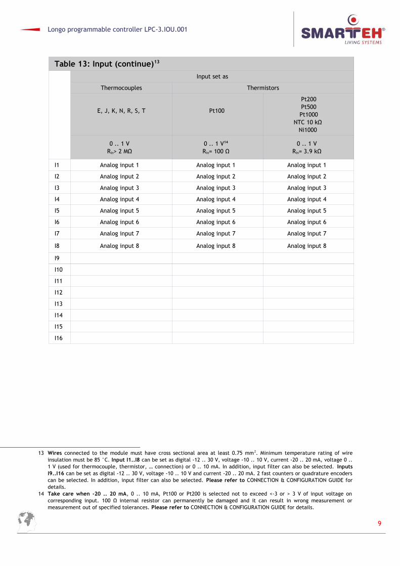
Table 13: Input (continue)13
Input set as
Thermocouples Thermistors
E, J, K, N, R, S, T Pt100
Pt200Pt500Pt1000
NTC 10 kΩ Ni1000
0 .. 1 VRin> 2 MΩ
0 .. 1 V14
Rin= 100 Ω0 .. 1 V
Rin= 3.9 kΩ
I1 Analog input 1 Analog input 1 Analog input 1
I2 Analog input 2 Analog input 2 Analog input 2
I3 Analog input 3 Analog input 3 Analog input 3
I4 Analog input 4 Analog input 4 Analog input 4
I5 Analog input 5 Analog input 5 Analog input 5
I6 Analog input 6 Analog input 6 Analog input 6
I7 Analog input 7 Analog input 7 Analog input 7
I8 Analog input 8 Analog input 8 Analog input 8
I9
I10
I11
I12
I13
I14
I15
I16
13 Wires connected to the module must have cross sectional area at least 0.75 mm2. Minimum temperature rating of wireinsulation must be 85 °C. Input I1..I8 can be set as digital -12 .. 30 V, voltage -10 .. 10 V, current -20 .. 20 mA, voltage 0 ..1 V (used for thermocouple, thermistor, … connection) or 0 .. 10 mA. In addition, input filter can also be selected. InputsI9..I16 can be set as digital -12 .. 30 V, voltage -10 .. 10 V and current -20 .. 20 mA. 2 fast counters or quadrature encoderscan be selected. In addition, input filter can also be selected. Please refer to CONNECTION & CONFIGURATION GUIDE fordetails.
14 Take care when -20 .. 20 mA, 0 .. 10 mA, Pt100 or Pt200 is selected not to exceed <-3 or > 3 V of input voltage oncorresponding input. 100 Ω internal resistor can permanently be damaged and it can result in wrong measurement ormeasurement out of specified tolerances. Please refer to CONNECTION & CONFIGURATION GUIDE for details.
9

Longo programmable controller LPC-3.IOU.001
Table 14: Digital output15
Source 11 .. 30 V DC16
Max. current per output = 1.2 AMax. output frequency = 50 Hz
Source 11 .. 30 V DC17
Max. current per output = 1.2 AMax. output frequency = 50 Hz
Q1 Digital output 1
Q2 Digital output 2
Q3 Digital output 3
Q4 Digital output 4
Q5 Digital output 5
Q6 Digital output 6
Q7 Digital output 7
Q8 Digital output 8
Q9 Digital output 9
Q10 Digital output 10
Q11 Digital output 11
Q12 Digital output 12
Q13 Digital output 13
Q14 Digital output 14
Q15 Digital output 15
Q16 Digital output 16
15 Wires connected to the module must have cross sectional area at least 0.75 mm2. Minimum temperature rating of wireinsulation must be 85 °C. Galvanic isolation (500 V AC) between digital outputs Q1..Q8, PS2.1, PS2.2, PS2.3, PS2.4 anddigital outputs Q9..Q16, PS3.1, PS3.2, PS3.3, PS3.4 and rest of the PLC circuit is provided.
16 Digital outputs Q1..Q8 are source type of outputs in reference to PS2.1/PS2.3 negative (-) voltage. Positive power supply isprovided from PS2.1 (+) / PS2.3 (+) connection. Please refer to CONNECTION & CONFIGURATION GUIDE for details.
17 Digital outputs Q9..Q16 are source type of outputs in reference to PS2.1/PS2.3 negative (-) voltage. Positive power supplyis provided from PS3.1 (+) / PS3.3 (+) connection. Please refer to CONNECTION & CONFIGURATION GUIDE for details.
10

Longo programmable controller LPC-3.IOU.001
3.3 Mounting instructions
Figure 3: Housing dimensions
Module surrounding area must be free for optimal cooling.
EXTERNAL SWITCH OR CIRCUIT-BREAKER AND EXTERNAL OVERCURRENTPROTECTION: The unit is allowed to be connected to installation with overcurrent protection that has nominal value of 6 A or less.RECOMMENDATION ON SWITCH OR CIRCUIT-BREAKER PROTECTION: There shouldbe two poles main switch in the installation in order to switch off the unit. Theswitch should meet the requirements of standard IEC60947 and have a nominalvalue at least 6 A. The switch or circuit-breaker should be within easy reach ofthe operator. It should be marked as the disconnecting device for the equipment.All connections, PLC attachments and assembling must be done while PLC is notconnected to the main power supply.Wires connected to the PLC must have cross sectional area at least 0.75 mm 2.Minimum temperature rating of wire insulation must be 85 °C.
1. Switch OFF external power supply PS1, PS2 and PS3.
2. Mount LPC-3 PLC to the provided place inside an electrical panel (DIN EN50022-35 railmounting).
3. Mount other LPC-3 PLC (if required). Mount each PLC to the DIN rail first and then makerequired connections or connect disconnect-able connectors.
4. Connect needed input, output and communication wires.
5. Switch ON power supply PS1, PS2 and PS3.
11

Longo programmable controller LPC-3.IOU.001
4 TECHNICAL SPECIFICATIONS
Table 15: General technical specifications
LPC-3.IOU.001 external power supply PS1 8 .. 30 V DC
LPC-3.IOU.001 external power consumption PS1 Max. 5 W
PS1 rated isolation voltage to PS2 and PS3 500 V AC
Digital output Q1..Q8 power supply PS2 11 .. 30 V DC
Maximum PS2 current 8 A
PS2 rated isolation voltage to PS1 and PS3 500 V AC
Digital output Q9..Q16 power supply PS3 11 .. 30 V DC
Maximum PS3 current 8 A
PS3 rated isolation voltage to PS1 and PS2 500 V AC
CAN1 isolation voltage to CAN2 2500 V DC
CAN1 or CAN2 isolation voltage to PS1, PS2, PS3 2500 V DC
Connection typeDisconnect-able spring type connectorsfor stranded wire 0.14 to 2.5 mm2
Ethernet RJ-45 10/100T IEEE 802.3i
USB B connector type, device mode, low speed, full speed
RTCcapacitor backed up with retention of cca. 30 days.
Dimensions (L x W x H) 110 x 100 x 35 mm
Weight 350 g
Ambient temperature 0 to 50 °C
Ambient humidity max. 95 %, no condensation
Maximum altitude 2000 m
Mounting position vertical
Transport and storage temperature -20 to 60 °C
Pollution degree 2
Over-voltage category II
Electrical equipment Class II (double insulation)
Protection class IP 30
12
Longo programmable controller LPC-3.IOU.001
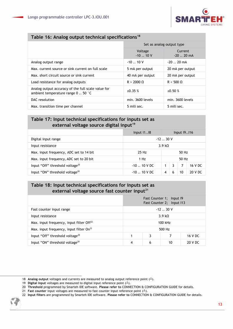
Table 16: Analog output technical specifications18
Set as analog output type
Voltage -10 .. 10 V
Current -20 .. 20 mA
Analog output range -10 .. 10 V -20 .. 20 mA
Max. current source or sink current on full scale 5 mA per output 20 mA per output
Max. short circuit source or sink current 40 mA per output 20 mA per output
Load resistance for analog outputs R > 2000 Ω R < 500 Ω
Analog output accuracy of the full scale value for ambient temperature range 0 .. 50 °C
±0.35 % ±0.50 %
DAC resolution min. 3600 levels min. 3600 levels
Max. transition time per channel 5 mili sec. 5 mili sec.
Table 17: Input technical specifications for inputs set as external voltage source digital input19
Input I1..I8 Input I9..I16
Digital input range -12 .. 30 V
Input resistance 3.9 kΩ
Max. input frequency, ADC set to 14 bit 25 Hz 50 Hz
Max. input frequency, ADC set to 20 bit 1 Hz 50 Hz
Input “Off” threshold voltage20 -10 .. 10 V DC 1 3 7 16 V DC
Input “ON” threshold voltage20 -10 .. 10 V DC 4 6 10 20 V DC
Table 18: Input technical specifications for inputs set as external voltage source fast counter input21
Fast Counter 1; Input I9 Fast Counter 2; Input I13
Fast counter input range -12 .. 30 V
Input resistance 3.9 kΩ
Max. input frequency, input filter Off22 100 kHz
Max. input frequency, input filter On22 500 Hz
Input “Off” threshold voltage20 1 3 7 16 V DC
Input “ON” threshold voltage20 4 6 10 20 V DC
18 Analog output voltages and currents are measured to analog output reference point (┴).19 Digital input voltages are measured to digital input reference point (┴).20 Threshold programmed by Smarteh IDE software. Please refer to CONNECTION & CONFIGURATION GUIDE for details. 21 Fast counter input voltages are measured to fast counter input reference point (┴).22 Input filters are programmed by Smarteh IDE software. Please refer to CONNECTION & CONFIGURATION GUIDE for details.
13

Longo programmable controller LPC-3.IOU.001
Table 19: Input technical specifications for inputs set as external voltage source quadrature encoder input23
Quadrature Encoder 1; Input I10(A), I11(B), I12(Reset) Quadrature Encoder 2; Input I14(A), I15(B), I16(Reset)
Quadrature encoder input range -12 .. 30 V
Input resistance 3.9 kΩ
Max. input frequency, input filter Off24 50 kHz
Max. input frequency, input filter On24 500 Hz
Input “Off” threshold voltage25 1 3 7 16 V DC
Input “On” threshold voltage25 4 6 10 20 V DC
Table 20: Input technical specifications for inputs I1..I16 set as analog input -10 .. 10 V26
ADC resolution set to
14 bit 20 bit
Analog input range -10 .. 10 V
Input resistance in unipolar connection 200 kΩ
Input resistance in differential connection 400 kΩ
Analog input accuracy of the full scale valuefor temperatures 20 .. 30 °C (unipolar and differential)
±0.25 %
Analog output accuracy of the full scale valuefor temperatures 0 .. 50 °C (unipolar and differential)
±0.35 %
ADC resolution when Min. 56000 levels Min. 900000 levels
Max. input frequency I1..I8 25 Hz 1 Hz
Max. input frequency, input filter Off I9..I16 25 Hz 1 Hz
Max. input frequency, input filter On I9..I16 10 Hz 1 Hz
23 Quadrature encoder input voltages are measured to quadrature encoder input reference point (┴).24 Input filters are programmed by Smarteh IDE software. Please refer to CONNECTION & CONFIGURATION GUIDE for details. 25 Threshold is programmed by Smarteh IDE software. Please refer to CONNECTION & CONFIGURATION GUIDE for details.26 Analog input -10 .. 10 V voltages are measured to analog input reference point (┴). Note: ADC set to 14bit resolution is
recommended for differential input setting.
14

Longo programmable controller LPC-3.IOU.001
Table 21: Input technical specifications for inputs I1..I8 set as analog input -20 .. 20 mA27
ADC resolution set to
14 bit 20 bit
Analog input range -20 .. 20 mA
Input resistance unipolar connection 100 Ω
Input resistance differential connection 200 Ω
Analog input accuracy of the full scale valuefor temperatures 20 .. 30 °C (unipolar and differential)
±0.45 %
Analog input accuracy of the full scale valuefor temperatures 0 .. 50 °C (unipolar and differential)
±0.65 %
ADC resolution when Min. 56000 levels Min. 900000 levels
Max. input frequency 25 Hz 1 Hz
Table 22: Input technical specifications for inputs I9..I16 set as analog input -20..20 mA27
ADC resolution set to
14 bit 20 bit
Analog input range -20 .. 20 mA
Input resistance unipolar connection 100 Ω
Input resistance differential connection 200 Ω
Analog input accuracy of the full scale valuefor temperatures 20 .. 30 °C unipolar and differential
±0.65 %
Analog input accuracy of the full scale valuefor temperatures 0 .. 50 °C unipolar and differential
±0.85 %
ADC resolution when Min. 56000 levels Min. 900000 levels
Max. input frequency off 25 Hz 1 Hz
Max. input frequency on 10 Hz 1 Hz
27 Analog input -20 .. 20 mA currents are measured to analog input reference point (┴). Note: ADC set to 14 bit resolution isrecommended.
15

Longo programmable controller LPC-3.IOU.001
Table 23: Input technical specifications for inputs I1..I8 set as unipolar analog input 0 .. 1 V28
Analog input range 0 .. 1 V
Input resistance unipolar and differential >2 MΩ
Analog input accuracy of the full scale valuefor temperatures 20 .. 30 °C unipolar
±0.02 %
Analog input accuracy of the full scale valuefor temperatures 0 .. 50 °C unipolar
±0.03 %
Analog input accuracy of the full scale value for0 .. 100 mV input voltage and temperatures 20 .. 30 °C
±0.005 %
Analog input accuracy of the full scale value for 0 .. 100 mV input voltage and temperatures 0 .. 50 °C
±0.007 %
ADC resolution (ADC set to 20 bit) Min. 1000000 levels
Max. input frequency 1 Hz
Table 24: Input technical specifications for inputs I1..I8 set as unipolar analog input 0 .. 10 mA29
Analog input range 0 .. 10 mA
Input resistance 100 Ω
Analog input accuracy of the full scale valuefor temperatures 20 .. 30 °C
±0.20 %
Analog output accuracy of the full scale valuefor temperatures 0 .. 50 °C
±0.30 %
ADC resolution (ADC set to 20 bit) Min. 1000000 levels
Max. input frequency 1 Hz
Table 25: Input technical specifications for 100 Ω input I1..I8 resistors30
Input resistance for temperatures 20 .. 30 °C ±0.15 %
Input resistance for temperatures 0 .. 50 °C ±0.20 %
Table 26: Input technical specifications for 100 Ω input I9..I16 resistors
Input resistance for temperatures 0 .. 50 °C ±0.50 %
28 Analog input 0 .. 1 V voltages are measured to analog input reference point (┴). Please refer to CONNECTION &CONFIGURATION GUIDE for details. Accuracies for thermocouple temperature measurements are written in Thermocoupleprogramming guide and accuracies for thermistor temperature measurements are written in Thermistor programmingguide chapter. Please refer to PROGRAMMING GUIDE chapter for details.
29 Analog input 0 .. 10 mA currents are measured to analog input reference point (┴). Please refer to CONNECTION &CONFIGURATION GUIDE for details.
30 100 Ω internal resistors on inputs I1..I8 are factory calibrated. Input resistor values are measured to input reference point(┴). Please refer to CONNECTION & CONFIGURATION GUIDE for details.
16

Longo programmable controller LPC-3.IOU.001
Table 27: Input technical specifications for 3.9 kΩ input I1..I8 resistors31
Input resistance for temperatures 20 .. 30 °C ±0.15 %
Input resistance for temperatures 0 .. 50 °C ±0.20 %
Table 28: Input technical specifications for 3.9 kΩ input I9..I16 resistors
Input resistance for temperatures 0 .. 50 °C ±0.50 %
Table 29: Input technical specifications for I1..I8 average junction temperature measurement32
Junction temperature measurement range33 -40 .. 125 °C
Resolution < 0.1 °C
Junction temperature measurement error 0 .. 50 °C < ±4 °C
Junction temperature measurement error 20 .. 30 °C < ±2 °C
31 3.9 kΩ internal resistors on inputs I1..I8 are factory calibrated. Input resistor values are measured to input referencepoint (┴). Please refer to CONNECTION & CONFIGURATION GUIDE for details. Additional more accurate results can beachieved by manually calibrate.
32 Junction temperature is typically used for thermocouple junction temperature compensation. It is average temperature ofI1..I8 terminals. For proper junction temperature measurement only PLC self cooling is allowed. Avoid external forcedcooling or heating of the PLC (e.g. fan cooling). Cooling required space around PLC must be respected, as written inMOUNTING INSTRUCTIONS. For more accurate thermocouple junction temperature measurement, external compensationtemperature sensor must be provided and connected to properly selected and programmed PLC input. Please refer toCONNECTION & CONFIGURATION GUIDE and PROGRAMMING GUIDE for details.
33 Note that LPC-3.IOU.001 can only operate when ambient temperature is in range between 0 .. 50 °C. Junctiontemperature measurement range is theoretical temperature range, that can be read.
17
Longo programmable controller LPC-3.IOU.001
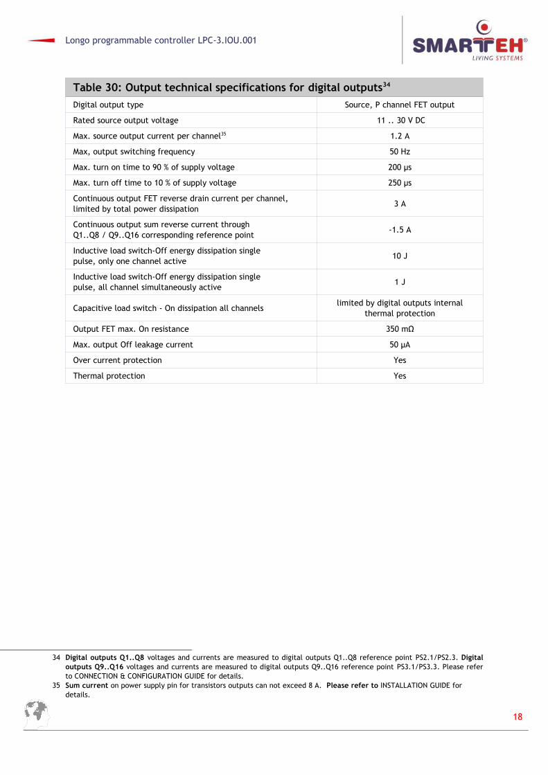
Table 30: Output technical specifications for digital outputs34
Digital output type Source, P channel FET output
Rated source output voltage 11 .. 30 V DC
Max. source output current per channel35 1.2 A
Max, output switching frequency 50 Hz
Max. turn on time to 90 % of supply voltage 200 µs
Max. turn off time to 10 % of supply voltage 250 µs
Continuous output FET reverse drain current per channel, limited by total power dissipation
3 A
Continuous output sum reverse current throughQ1..Q8 / Q9..Q16 corresponding reference point
-1.5 A
Inductive load switch-Off energy dissipation singlepulse, only one channel active
10 J
Inductive load switch-Off energy dissipation singlepulse, all channel simultaneously active
1 J
Capacitive load switch - On dissipation all channelslimited by digital outputs internal
thermal protection
Output FET max. On resistance 350 mΩ
Max. output Off leakage current 50 µA
Over current protection Yes
Thermal protection Yes
34 Digital outputs Q1..Q8 voltages and currents are measured to digital outputs Q1..Q8 reference point PS2.1/PS2.3. Digitaloutputs Q9..Q16 voltages and currents are measured to digital outputs Q9..Q16 reference point PS3.1/PS3.3. Please referto CONNECTION & CONFIGURATION GUIDE for details.
35 Sum current on power supply pin for transistors outputs can not exceed 8 A. Please refer to INSTALLATION GUIDE for details.
18

Longo programmable controller LPC-3.IOU.001
5 CONNECTION & CONFIGURATION GUIDE
5.1 Main connection scheme & configuration
Figure 4: PLC main connection scheme36
36 Coloured areas represents galvanic isolated areas. Please refer to General technical specifications in chapter TECHNICALSPECIFICATIONS for details.
19

Longo programmable controller LPC-3.IOU.001
Figure 5: Grounding possibilities37
a) All PLC negative power supply poles connected together on to the Protective Earth (PE) functional earthing.
b) All PLC negative power supply poles connected together but not to the Protective Earth (PE) functional earthing.
37 Potential differences between any two negative power supply poles could not exceed prescribed values. Please refer toTECHNICAL SPECIFICATIONS for details.
20

Longo programmable controller LPC-3.IOU.001
Figure 5: Grounding possibilities38
c) Not any PLC negative power supply poles connected together or to the Protective Earth (PE) functional earthing.
d) Mixed connection where required, selected PLC negative power supply poles connectedtogether and/or to the Protective Earth (PE) functional earthing.
38 Potential differences between any two negative power supply poles could not exceed prescribed values. Please refer toTECHNICAL SPECIFICATIONS for details.
21

Longo programmable controller LPC-3.IOU.001
Figure 6: Main configuration of the PLC39
Smarteh IDE configuration interface.
Smarteh IDE flash uploader page.
39 Configuration of the PLC is done using Smarteh IDE software tool. Please refer to PROGRAMMING GUIDE for details.
22

Longo programmable controller LPC-3.IOU.001
5.2 Digital input connection scheme & configuration guide
Figure 7: Digital input I1..I16 connection scheme40
a) Voltage free contact connection to PLC input.
b) Active voltage source or push/pull output connection to PLC input.
c) Active voltage sink output connection to PLC input.
40 Inputs I1..I16 are not galvanic isolated between each other and to the rest of the PLC circuit on the same referencepotential (┴). For galvanic isolation of the PLC I1..I16 inputs to inputs on other LPC-3.IOU, use CAN1/CAN2 galvanicisolated communication ports for data exchanging. Digital outputs Q1..Q8 and Q9..Q16 on the same LPC-3.IOU PLC aregalvanic isolated to inputs I1..I16. Use galvanic isolated free contacts and/or digital input voltage sources.
23
Longo programmable controller LPC-3.IOU.001
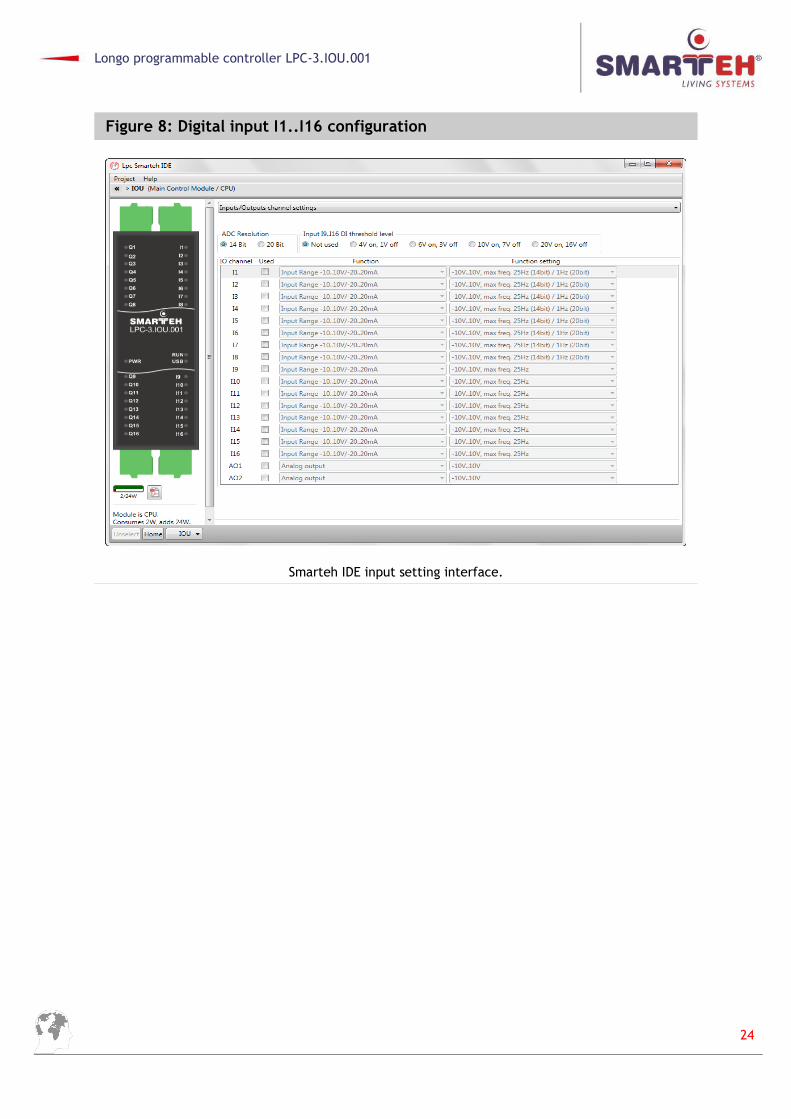
Figure 8: Digital input I1..I16 configuration
Smarteh IDE input setting interface.
24

Longo programmable controller LPC-3.IOU.001
5.3 Digital output connection scheme & configuration guide
Figure 9: Digital output Q1..Q16 connection scheme41
a) PLC digital output Q1..Q8 connection to loads.
b) PLC digital output Q9..Q16 connection to loads.
NOTE: Digital output Q1..Q16 signals are always available in Smarteh IDE.
41 Outputs Q1..Q8 are galvanic isolated to outputs Q9..Q16, to inputs I1..I16 and to the rest of the PLC circuit on the samereference potential (┴).
25

Longo programmable controller LPC-3.IOU.001
5.4 Analog input -10 .. 10 V connection scheme & configuration guide
Figure 10: Analog input I1..I16, -10 .. 10 V connection scheme42
a) Unipolar connection of active voltage source/transducer -10 .. 10 V to PLC input.
b) Differential connection of active voltage source/transducer -10 .. 10 V to PLC input.
42 Inputs I1..I16 are not galvanic isolated between each other and to the rest of the PLC circuit on the same referencepotential (┴). For galvanic isolation of the PLC I1..I16 inputs to inputs on other LPC-3.IOU, use CAN1/CAN2 galvanicisolated communication ports for data exchanging. Digital outputs Q1..Q8 and Q9..Q16 on the same LPC-3.IOU PLC aregalvanic isolated to inputs I1..I16. Cables for wiring analog signals must be shielded twisted-pair type. This reduce but noteliminate interferences. Potential difference between the cable shield end and earth potential may cause current throughthe shield which cause unwanted disturbance. To avoid this effect ground only one end of the cable shielding. Use galvanicisolated analog input voltage sources.
26

Longo programmable controller LPC-3.IOU.001
Figure 11: Analog input I1..I16, -10 .. 10 V configuration43
43 Configuration of the PLC is done using Smarteh IDE software tool. Please refer to PROGRAMMING GUIDE for details.
27
Longo programmable controller LPC-3.IOU.001
5.5 Analog input -20 .. 20 mA connection scheme & configuration guide
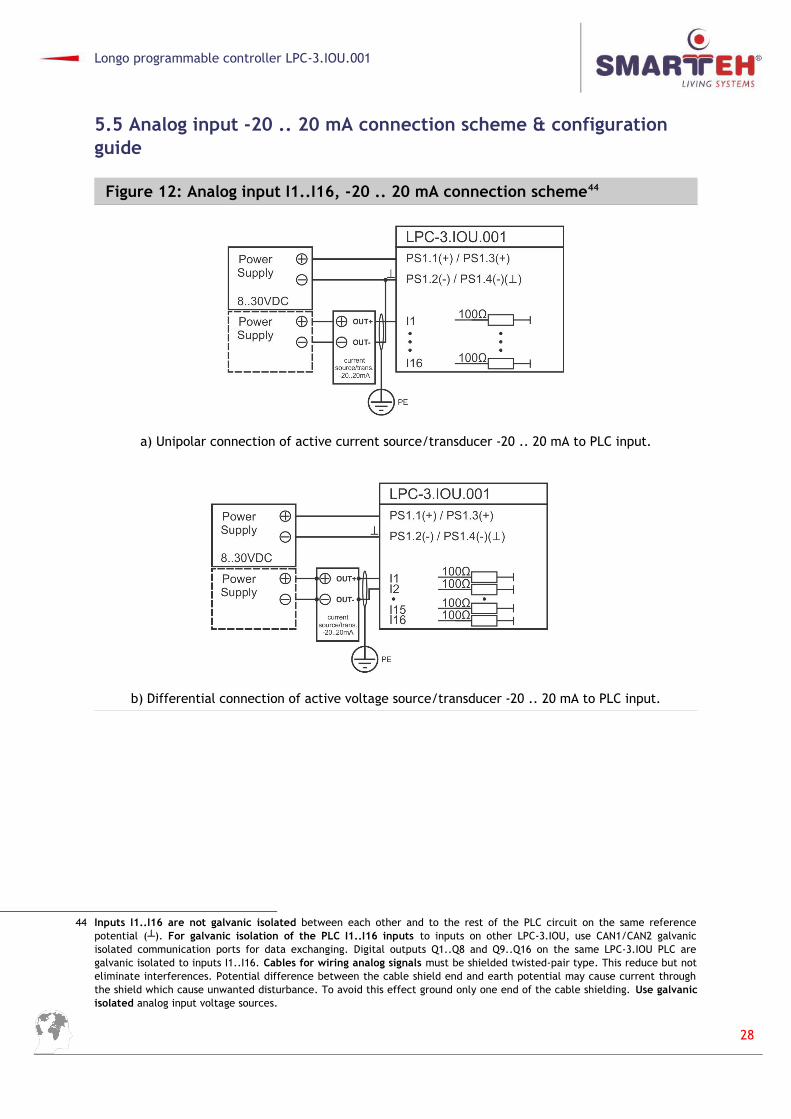
Figure 12: Analog input I1..I16, -20 .. 20 mA connection scheme44
a) Unipolar connection of active current source/transducer -20 .. 20 mA to PLC input.
b) Differential connection of active voltage source/transducer -20 .. 20 mA to PLC input.
44 Inputs I1..I16 are not galvanic isolated between each other and to the rest of the PLC circuit on the same referencepotential (┴). For galvanic isolation of the PLC I1..I16 inputs to inputs on other LPC-3.IOU, use CAN1/CAN2 galvanicisolated communication ports for data exchanging. Digital outputs Q1..Q8 and Q9..Q16 on the same LPC-3.IOU PLC aregalvanic isolated to inputs I1..I16. Cables for wiring analog signals must be shielded twisted-pair type. This reduce but noteliminate interferences. Potential difference between the cable shield end and earth potential may cause current throughthe shield which cause unwanted disturbance. To avoid this effect ground only one end of the cable shielding. Use galvanicisolated analog input voltage sources.
28

Longo programmable controller LPC-3.IOU.001
Figure 13: Analog input I1..I16, -20 .. 20 mA configuration45
45 Configuration of the PLC is done using Smarteh IDE software tool. Please refer to PROGRAMMING GUIDE for details.
29

Longo programmable controller LPC-3.IOU.001
5.6 Analog input 0 .. 1 V connection scheme & configuration guide
Figure 14: Analog input I1..I8, 0 .. 1 V connection scheme46
Unipolar connection of active voltage source/transducer 0 .. 1 V to PLC input.
46 Inputs I1..I16 are not galvanic isolated between each other and to the rest of the PLC circuit on the same referencepotential ( ). ┴ For galvanic isolation of the PLC I1..I16 inputs to inputs on other LPC-3.IOU, use CAN1/CAN2 galvanicisolated communication ports for data exchanging. Digital outputs Q1..Q8 and Q9..Q16 on the same LPC-3.IOU PLC aregalvanic isolated to inputs I1..I16. Cables for wiring analog signals must be shielded twisted-pair type. This reduce but noteliminate interferences. Potential difference between the cable shielded end and earth potential may cause currentthrough the shield which cause unwanted disturbance. To avoid this effect ground only one end of the cable shielding. Usegalvanic isolated analog input voltage sources.
30

Longo programmable controller LPC-3.IOU.001
Figure 15: Analog input I1..I8, 0 .. 1 V configuration47
47 Configuration of the PLC is done using Smarteh IDE software tool. Please refer to PROGRAMMING GUIDE for details.
31
Longo programmable controller LPC-3.IOU.001
5.7 Analog input 0 .. 10 mA connection scheme & configuration guide
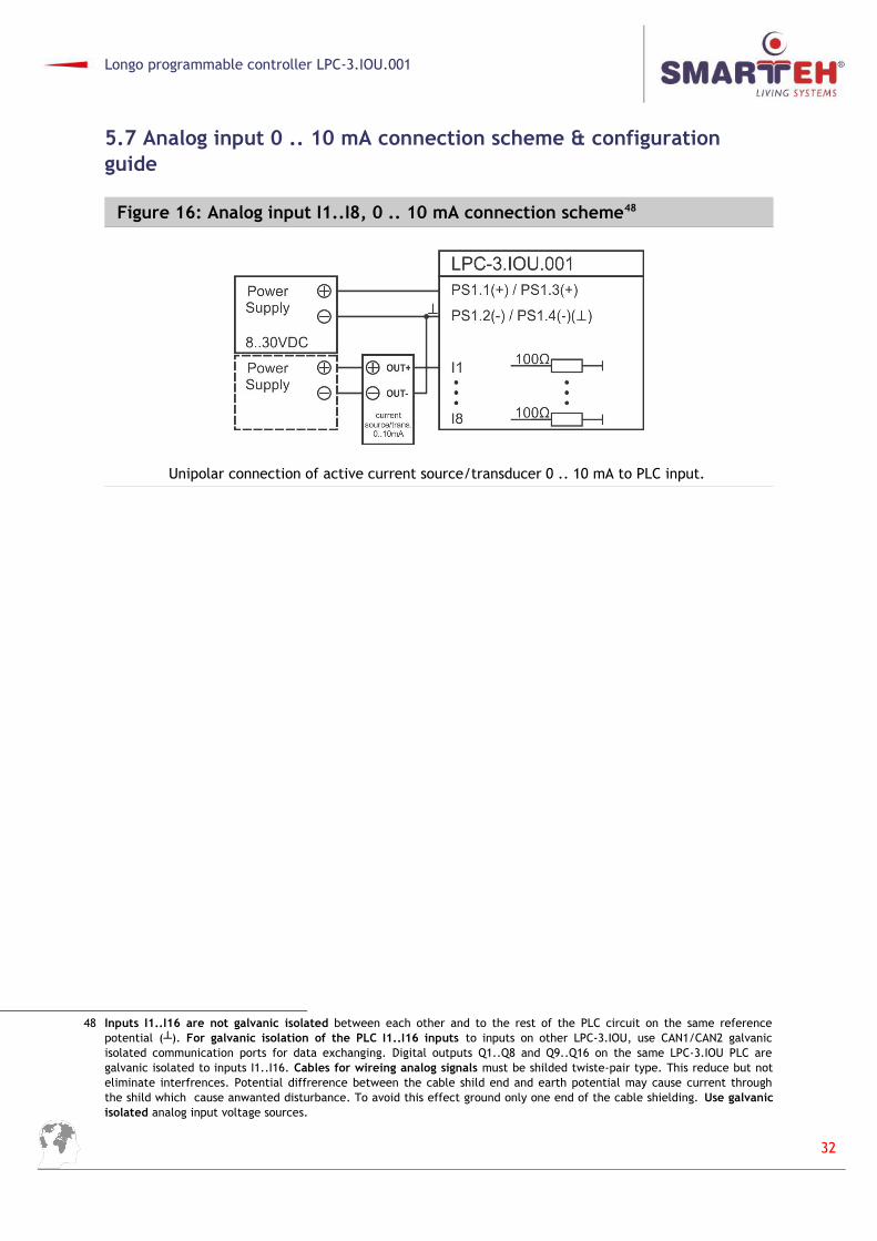
Figure 16: Analog input I1..I8, 0 .. 10 mA connection scheme48
Unipolar connection of active current source/transducer 0 .. 10 mA to PLC input.
48 Inputs I1..I16 are not galvanic isolated between each other and to the rest of the PLC circuit on the same referencepotential (┴). For galvanic isolation of the PLC I1..I16 inputs to inputs on other LPC-3.IOU, use CAN1/CAN2 galvanicisolated communication ports for data exchanging. Digital outputs Q1..Q8 and Q9..Q16 on the same LPC-3.IOU PLC aregalvanic isolated to inputs I1..I16. Cables for wireing analog signals must be shilded twiste-pair type. This reduce but noteliminate interfrences. Potential diffrerence between the cable shild end and earth potential may cause current throughthe shild which cause anwanted disturbance. To avoid this effect ground only one end of the cable shielding. Use galvanicisolated analog input voltage sources.
32

Longo programmable controller LPC-3.IOU.001
Figure 17: Analog input I1..I8, 0..10 mA configuration49
49 Configuration of the PLC is done using Smarteh IDE software tool. Please refer to PROGRAMMING GUIDE for details.
33

Longo programmable controller LPC-3.IOU.001
5.8 Thermocouple connection scheme & configuration guide
Figure 18: Analog input I1..I8, thermocouple connection scheme50
Unipolar connection of thermocouple temperature sensing element to PLC input.
NOTE: Using this method only allows measuring temperatures higher than junction temperature.
50 Inputs I1..I16 are not galvanic isolated between each other and to the rest of the PLC circuit on the same referencepotential ( ). ┴ For galvanic isolation of the PLC I1..I16 inputs to inputs on other LPC-3.IOU, use CAN1/CAN2 galvanicisolated communication ports for data exchanging. Digital outputs Q1..Q8 and Q9..Q16 on the same LPC-3.IOU PLC aregalvanic isolated to inputs I1..I16. Cables for wiring analog signals must be shielded twisted-pair type. This reduce but noteliminate interferences. Potential difference between the cable shielded end and earth potential may cause currentthrough the shield which cause unwanted disturbance. To avoid this effect ground only one end of the cable shielding. Usegalvanic isolated analog input voltage sources. Accuracies for thermocouple temperature measurements are written inThermocouple programming guide chapter. Please refer to PROGRAMMING GUIDE chapter for details.
34

Longo programmable controller LPC-3.IOU.001
Figure 19: Analog input I1..I8, thermocouple configuration51
51 Configuration of the PLC is done using Smarteh IDE software tool. Please refer to PROGRAMMING GUIDE for details.
35

Longo programmable controller LPC-3.IOU.001
5.9 Thermistor connection scheme & configuration guide
Figure 20: Analog input I1..I8, thermistor connection scheme52
a) Pt100 connection of thermistor temperature sensing element to PLC input.
b) Pt200, Pt500, Pt1000, Ni1000, NTC10 kΩ connection of thermistor temperature sensingelement to PLC input.
52 Inputs I1..I16 are not galvanic isolated between each other and to the rest of the PLC circuit on the same referencepotential ( ). ┴ For galvanic isolation of the PLC I1..I16 inputs to inputs on other LPC-3.IOU, use CAN1/CAN2 galvanicisolated communication ports for data exchanging. Digital outputs Q1..Q8 and Q9..Q16 on the same LPC-3.IOU PLC aregalvanic isolated to inputs I1..I16. Cables for wiring analog signals must be shielded twisted-pair type. This reduce but noteliminate interferences. Potential difference between the cable shielded end and earth potential may cause currentthrough the shield which cause unwanted disturbance. To avoid this effect ground only one end of the cable shielding. Usegalvanic isolated analog input voltage sources. Accuracies for thermistor temperature measurements are written inThermistor programming guide chapter. Please refer to PROGRAMMING GUIDE chapter for details.
36

Longo programmable controller LPC-3.IOU.001
Figure 21: Analog input I1..I8, thermistor configuration53
Thermistor options are Pt100 or Pt200/Pt500/Pt1000/NTC 10k/Ni 1000.
53 Configuration of the PLC is done using Smarteh IDE software tool. Please refer to PROGRAMMING GUIDE for details.
37

Longo programmable controller LPC-3.IOU.001
5.10 Fast counter connection scheme & configuration guide
Figure 22: Fast counter digital input I9 & I13 connection scheme54
a) Voltage free contact fast counter connection to PLC input.
b) Active voltage source or push/pull fast counter output connection to PLC input.
c) Active voltage sink fast counter output connection to PLC input.
54 Inputs I1..I16 are not galvanic isolated between each other and to the rest of the PLC circuit on the same referencepotential (┴). For galvanic isolation of the PLC I1..I16 inputs to inputs on other LPC-3.IOU, use CAN1/CAN2 galvanicisolated communication ports for data exchanging. Digital outputs Q1..Q8 and Q9..Q16 on the same LPC-3.IOU PLC aregalvanic isolated to inputs I1..I16. Use galvanic isolated free contacts and/or digital input voltage sources.
38
Longo programmable controller LPC-3.IOU.001
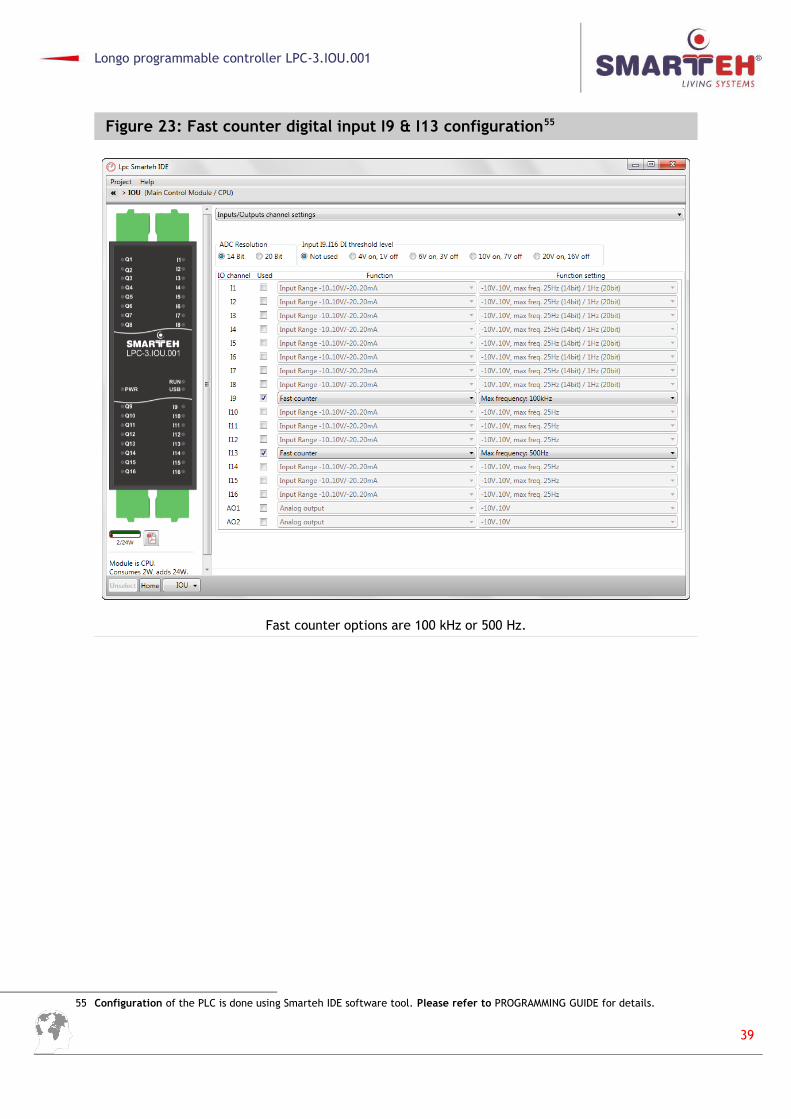
Figure 23: Fast counter digital input I9 & I13 configuration55
Fast counter options are 100 kHz or 500 Hz.
55 Configuration of the PLC is done using Smarteh IDE software tool. Please refer to PROGRAMMING GUIDE for details.
39

Longo programmable controller LPC-3.IOU.001
5.11 Quadrature encoder connection scheme & configuration guide
Figure 24: Quadrature encoder digital input I10, I11, I12 & I14, I15, I16 connection scheme56
a) Voltage free contact fast counter connection to PLC input.
b) Active voltage source or push/pull fast counter output connection to PLC input.
c) Active voltage sink fast counter output connection to PLC input.
56 Inputs I1..I16 are not galvanic isolated between each other and to the rest of the PLC circuit on the same referencepotential (┴). For galvanic isolation of the PLC I1..I16 inputs to inputs on other LPC-3.IOU, use CAN1/CAN2 galvanicisolated communication ports for data exchanging. Digital outputs Q1..Q8 and Q9..Q16 on the same LPC-3.IOU PLC aregalvanic isolated to inputs I1..I16. Use galvanic isolated free contacts and/or digital input voltage sources.
40

Longo programmable controller LPC-3.IOU.001
Figure 25: Quadrature encoder digital input I10, I11, I12 & I14, I15, I16 configuration57
NOTE: This input detects a reference position for the Quadrature Decoder. When using reset input,if inputs A, B, and reset are all zero, the counter is also reset to zero. Reset can be triggered withhardware signal or from PLC application with QuadDec_Reset.
57 Configuration of the PLC is done using Smarteh IDE software tool. Please refer to PROGRAMMING GUIDE for details.
41

Longo programmable controller LPC-3.IOU.001
6 PROGRAMMING GUIDE
6.1 Basic programming
There are several logical units attached with this module. They can be accessed from the SmartehIDE application. Some units are enabled by default, others can be enabled through Smarteh IDE. Unitis enabled when any of its variables is used.
PLC has 32 kB of non-volatile memory, which is available to any variable used inside applicationsimply by setting the variable Option to Retain.
PLC also provides 4 kB of ROM (flash) memory area to the user who would like to use someinitialization data or some fixed parameters. This area can be accessed from application only forreading. Setting the values of variables in Flash can be issued with Flash uploader page.In Flash memory area there are some preloaded data stored:
MAC: is unique for every unit produced. This value can be also found on the label attachedon the housing of the unit.
IP: default value is 192.168.19.225
MASK: default value is 255.255.255.0
Gateway, Primary DNS, Secondary DNS: default 0.0.0.0
Flash memory unitThis unit enables only reading from its variables. Setting the variables is issued with one of SmartehIDE plugins, Flash uploader page.Flash unit provides reading of a portion of a flash memory inside MC8 module. Flash memory is non-volatile, therefore keeps data forever.
Usually this area is used for setting some data to the default value even before installation of theunit to its position. After, when PLC is commissioned, the data are already present and there is noneed for further setting. This keeps its data in area and some startup parameters can be written.
RTC and NVRAM unitFor RTC back-up and for Retain variables stored in NVRAM, there is Super Capacitor instead ofbattery integrated inside PLC. This way replacement of the discharged battery is avoided. TheRetention time is minimum 30 days from the power down.
RTC time provides date and time information. Along, alarming function is also supported.
Modbus slave unit
Modbus TCP/IP slave has 512 addresses in each memory section.
Coils: 00000 to 00511Discrete Inputs: 10000 to 10511Input Register: 30000 to 30511Holding Registers: 40000 to 40511
Supports up to 3 connections to the slave unit. Scan rate is 500 ms or greater.
42

Longo programmable controller LPC-3.IOU.001
CANopen unit
CANopen unit consists of Master (CAN1) and Slave (CAN2) communication ports. They areindependent, thus can be connected to two different CAN network at the same time.
The ports can operate at baud rates 50 kbps, 125 kbps or 250 kbps.
It follows the internationally standardized (EN 50325-4) CAN-based higher-layer protocol forembedded control systems. Advised rules and concepts by this standard must be followed to fulfillthe conditions and so achieving normal operation and results.
The structure of the network as cable type and lengths, baud rates, number of the nodes andtermination must be taken into account within the recommendations and requirements, whendesigning the network.
The bus network can consist of at least one Master and at least one Slave node by the standard, butit is advised that with increased number of nodes, the Master node fastest interval is reduced. Beloware two examples:
Example 1: network with 1 master and 9 slaves, every slave have defined 32 (4x8) byte of data andbaud rate 125 Kbps. Fastest Cycle time for this configuration is 50 ms.
Example 2: network with 1 master and 4 slaves, every slave have defined 4 byte of data and baudrate 250 Kbps. Fastest Cycle time for this configuration is 5 ms.
5 millisecond is the fastest recommended cycle time.
It is recommended to power-up all the nodes on the same network at the same time, if some or allnodes had been reprogrammed (to reinitialize the communication properly).
Additional operational information
After the installation of the PLC it must be at least 20 minutes on external power supply, before theinternal super capacitor is charged and the retain memory is ready to save variables without loosingthem switching power supply off.
RUN / STOP Switch
Run: Status (RUN) LED on indicate that the PLC program is up and user program is running.
Stop: When the switch is turn to STOP state, the status (RUN) LED is Off. The application switch tothe boot loader, this fact allow users to program LPC-3.IOU.001.
When the user is done programming, the PLC via USB, the switch must be turned ON and theLPC-3.IOU.001 starts the application.
PLC task cycle time
Main PLC task interval (under Project tab Resource Tasks Interval) time is not recommended→ → →to be set lower than 5 ms.
43

Longo programmable controller LPC-3.IOU.001
6.2 Digital input I1..I8 programming
Figure 26: Digital Input I1..I8 LD language example58
6.3 Digital input I9..I16 programming
Figure 27: Digital Input I9..I16 LD language example59
58 Configuration of the PLC is done using Smarteh IDE software tool. Please refer to PROGRAMMING GUIDE for details.
44

Longo programmable controller LPC-3.IOU.001
6.4 Digital output Q1..Q16 programming
Figure 28: Digital output Q1..Q16 LD language example59
6.5 Analog input unipolar -10 .. 10 V programming
Figure 29: Analog input unipolar -10 .. 10 V LD language example60
59 Configuration of the PLC is done using Smarteh IDE software tool. Please refer to PROGRAMMING GUIDE for details.
45

Longo programmable controller LPC-3.IOU.001
6.6 Analog input differential -10 .. 10 V programming
Figure 30: Analog input differential -10 .. 10 V LD language example60
6.7 Analog input unipolar -20 .. 20 mA programming
Figure 31: Analog input unipolar -20 .. 20 mA LD language example61
60 14 bits ADC settings should be used for better common mode interference (CMI) filtering. Configuration of the PLC is done using Smarteh IDE software tool. Please refer to PROGRAMMING GUIDE for details.
61 Configuration of the PLC is done using Smarteh IDE software tool. Please refer to PROGRAMMING GUIDE for details.
46

Longo programmable controller LPC-3.IOU.001
6.8 Analog input differential -20 .. 20 mA programming
Figure 32: Analog input differential -20 .. 20 mA LD language example62
6.9 Analog input unipolar 0 .. 1 V programming
Figure 33: Analog input unipolar 0 .. 1 V LD language example63
62 14 bits ADC settings should be used for better common mode interference (CMI) filtering. Configuration of the PLC is doneusing Smarteh IDE software tool. Please refer to PROGRAMMING GUIDE for details.
63 Measurement accuracy using filters will heavily increase => + 25 µV. Configuration of the PLC is done using Smarteh IDEsoftware tool. Please refer to PROGRAMMING GUIDE for details.
47

Longo programmable controller LPC-3.IOU.001
6.10 Analog input 0 .. 10 mA programming
Figure 34: Analog input 0 .. 10 mA LD language example64
6.11 Analog output 0 .. 10 mA programming
Figure 35: Analog output 0 .. 10 mA LD language example65
64 Configuration of the PLC is done using Smarteh IDE software tool. Please refer to PROGRAMMING GUIDE for details.
48

Longo programmable controller LPC-3.IOU.001
6.12 Thermocouple programming
Figure 36: Thermocouple LD language example65
6.13 Thermistor programming
Figure 37: Thermistor LD language example66
65 Configuration of the PLC is done using Smarteh IDE software tool. Please refer to PROGRAMMING GUIDE for details.
49

Longo programmable controller LPC-3.IOU.001
6.14 Fast counter programming
Figure 38: Fast counter LD language example66
66 Configuration of the PLC is done using Smarteh IDE software tool. Please refer to PROGRAMMING GUIDE for details.
50

Longo programmable controller LPC-3.IOU.001
6.15 Quadrature encoder programming
Figure 39: Quadrature encoder LD language example67
51

Longo programmable controller LPC-3.IOU.001
7 MODULE LABELING
Figure 40: Labels on housing
Label 1 (sample): Label 2 (sample):
Label 1 descriptions:
1. LPC-3.IOU.001 is the full product name.2. P/N: 226IOU14001001 is the part number.
• 226 – general code for product family,
• IOU – short product name,
• 14001 – sequence code,
• 14 – year of code opening,
• 001 – derivation code,
• 001 – version code (reserved for future HW and/or SW firmware upgrades).
3. D/C: 05/15 is the date code.
• 05 – week and
• 15 – year of production.
Label 2 descriptions:
1. S/N:IOU-S9-1500000190 is the serial number.
• IOU – short product name,
• S9 – user code (test procedure, e.g. Smarteh person xxx),
• 1500000190 – year and current stack code,
• 15 – year (last two digits),
• 00000190 – current stack number; previous module would have the stack number00000189 and the next one 00000191.
52
LPC-3.IOU.001P/N:226IOU14001001D/C: 05/15
S/N: IOU-S9-1500000190

Longo programmable controller LPC-3.IOU.001
8 CHANGES
The following table describes all the changes to the document.
Date V. Description
01.03.15 1 The initial version, issued as LPC-3.IOU.001 UserManual.
01.09.15 2 Technical update.
01.02.16 3 Update figures 19, 21. Added thermocouples note. Page 2 description update.
53

Longo programmable controller LPC-3.IOU.001
9 NOTES
54

Longo programmable controller LPC-3.IOU.001
55