grundfos magna, geni module - free hot water · grundfos magna, geni module installation and...
TRANSCRIPT

GRUNDFOS INSTRUCTIONS
Grundfos MAGNA, GENI ModuleInstallation and operating instructions
Grundfos.bk Page 1 Wednesday, September 22, 2010 8:44 PM

2
Grundfos.bk Page 2 Wednesday, September 22, 2010 8:44 PM
3
Grundfos MAGNA, GENI Module
Installation and operating instructions
4
Grundfos.bk Page 3 Wednesday, September 22, 2010 8:44 PM

Grundfos.bk Page 4 Wednesday, September 22, 2010 8:44 PM
LIMITED WARRANTYProducts manufactured by GRUNDFOS PUMPS CORPORATION (Grundfos) are warranted to the original user only to be free of defects in material and workmanship for a period of 24 months from date of manufacture. Grundfos' liability under this warranty shall be limited to repairing or replacing at Grundfos' option, without charge, F.O.B. Grundfos' factory or authorized service station, any product of Grundfos' manufacture. Grundfos will not be liable for any costs of removal, installation, transportation, or any other charges which may arise in connection with a warranty claim. Products which are sold but not manufactured by Grundfos are subject to the warranty provided by the manufacturer of said products and not by Grundfos' warranty. Grundfos will not be liable for damage or wear to products caused by abnormal operating conditions, accident, abuse, misuse, unauthorized alteration or repair, or if the product was not installed in accordance with Grundfos' printed installation and operating instructions.
To obtain service under this warranty, the defective product must be returned to the distributor or dealer of Grundfos' products from which it was purchased together with proof of purchase and installation date, failure date, and supporting installation data. Unless otherwise provided, the distributor or dealer will contact Grundfos or an authorized service station for instructions. Any defective product to be returned to Grundfos or a service station must be sent freight prepaid; documentation supporting the warranty claim and/or a Return Material Authorization must be included if so instructed.
GRUNDFOS WILL NOT BE LIABLE FOR ANY INCIDENTAL OR CONSEQUENTIAL DAMAGES, LOSSES, OR EXPENSES ARISING FROM INSTALLATION, USE, OR ANY OTHER CAUSES. THERE ARE NO EXPRESS OR IMPLIED WARRANTIES, INCLUDING MERCHANTABILITY OR FITNESS FOR A PARTICULAR PURPOSE, WHICH EXTEND BEYOND THOSE WARRANTIES DESCRIBED OR REFERRED TO ABOVE.
Some jurisdictions do not allow the exclusion or limitation of incidental or consequential damages and some jurisdictions do not allow limit actions on how long implied warranties may last. Therefore, the above limitations or exclusions may not apply to you. This warranty gives you specific legal rights and you may also have other rights which vary from jurisdiction to jurisdiction.
4
Grundfos.bk Page 5 Wednesday, September 22, 2010 8:44 PM
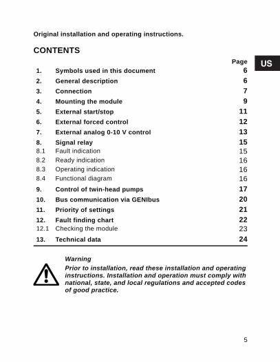
Original installation and operating instructions.
CONTENTSPage
1. Symbols used in this document 62. General description 63. Connection 74. Mounting the module 95. External start/stop 116. External forced control 127. External analog 0-10 V control 138. Signal relay 158.1 Fault indication 158.2 Ready indication 168.3 Operating indication 168.4 Functional diagram 169. Control of twin-head pumps 1710. Bus communication via GENIbus 2011. Priority of settings 2112. Fault finding chart 2212.1 Checking the module 2313. Technical data 24
WarningPrior to installation, read these installation and operating instructions. Installation and operation must comply with national, state, and local regulations and accepted codes of good practice.
5
Grundfos.bk Page 6 Wednesday, September 22, 2010 8:44 PM
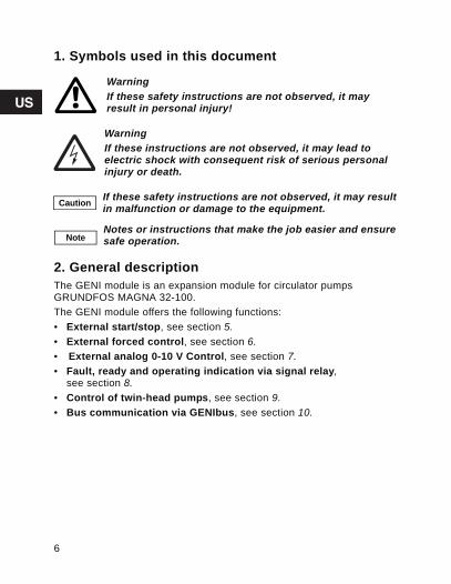
1. Symbols used in this document
2. General descriptionThe GENI module is an expansion module for circulator pumpsGRUNDFOS MAGNA 32-100.The GENI module offers the following functions:• External start/stop, see section 5.• External forced control, see section 6.• External analog 0-10 V Control, see section 7. • Fault, ready and operating indication via signal relay,
see section 8.• Control of twin-head pumps, see section 9.• Bus communication via GENIbus, see section 10.
WarningIf these safety instructions are not observed, it may result in personal injury!
WarningIf these instructions are not observed, it may lead to electric shock with consequent risk of serious personal injury or death.
Caution If these safety instructions are not observed, it may result in malfunction or damage to the equipment.
NoteNotes or instructions that make the job easier and ensure safe operation.
6

Grundfos.bk Page 7 Wednesday, September 22, 2010 8:44 PM
3. ConnectionThe electrical connection and protection must be carried out inaccordance with local regulations. The GENI module is powered wirelessly from the pump.To ensure correct function, follow the instructions in section4. Mounting the module.
N
Caution• All cables must be heat-resistant up to +185 °F (+85°C).• All cables must be installed in accordance with National Electric Code.
Wires connected to• outputs NC, NO, C and• inputs Start/stop, A, Y, B, MIN, MAX, 10 V, X, Q, Z must be electrically isolated from each other.
7
Grundfos.bk Page 8 Wednesday, September 22, 2010 8:44 PM
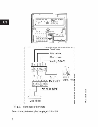
Fig. 1 Connection terminals
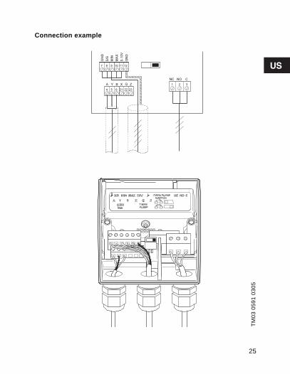
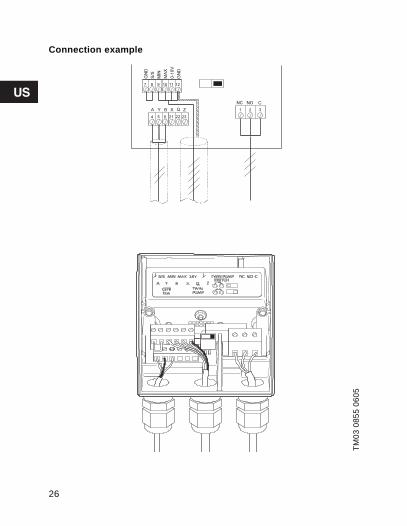
See connection examples on pages 25 to 28.
TM03
087
8 09
05
Start/stop
Max. curve
Min. curve
Analog 0-10 V
Twin-head pump
DC 0-10 V
Bus signal
Signal relay
8

Grundfos.bk Page 9 Wednesday, September 22, 2010 8:44 PM
4. Mounting the module
TM03
088
1 07
05
1. Align the two hooks on the module.
2. Gently push the module into place so that the hooks engage with the control box.
TM03
088
0 07
05
3. Check that the module and the control box touch each other.
4. Check that the two hooks of the module engagecorrectly with the control box.
5. Fasten the module with the screw.
2
1
35
4
9
Grundfos.bk Page 10 Wednesday, September 22, 2010 8:44 PM
TM03
089
6 07
05
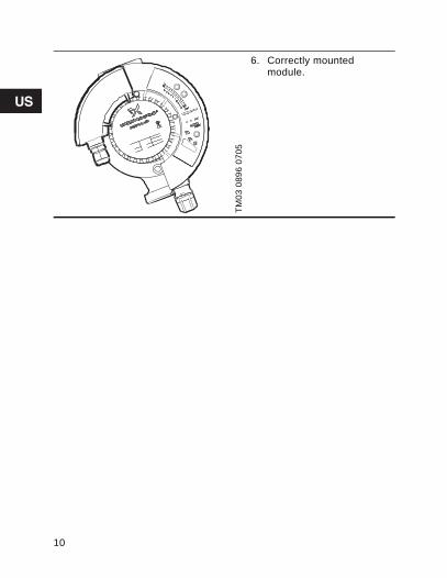
6. Correctly mountedmodule.
10

Grundfos.bk Page 11 Wednesday, September 22, 2010 8:44 PM
5. External start/stop The GENI module incorporates a digital input for an external contact. The pump can be started and stopped via this input. When started, the pump will operate with the setpoint set on the control panel or with the R100.
Functional diagram: Start/stop input
NoteIf the external contact is used, the connection betweenterminals 7 and 8 must be replaced by the external connection.
Contact position Function
Stop of pump
Start of pump
11
Grundfos.bk Page 12 Wednesday, September 22, 2010 8:44 PM
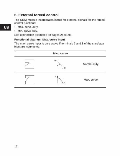
6. External forced controlThe GENI module incorporates inputs for external signals for the forced-control functions:• Max. curve duty.• Min. curve duty.See connection examples on pages 25 to 28.
Functional diagram: Max. curve inputThe max. curve input is only active if terminals 7 and 8 of the start/stop input are connected.
Max. curve
Normal duty
Max. curve
Q
H
Q
H
12

Grundfos.bk Page 13 Wednesday, September 22, 2010 8:44 PM
Functional diagram: Min. curve inputThe min. curve input is only active if• terminals 7 and 8 of the start/stop input are connected and• terminals 7 and 10 of the max. curve input are not connected.
7. External analog 0-10 V controlThe GENI module has an input for an external 0-10 VDC analog signal transmitter. Via this input, the pump can be controlled by an externalcontroller if the pump has been set to one of the following control modes:• Constant curve
The external analog signal will control the pump curve within the range from the min. curve to the constant curve selected according to the characteristic in fig. 2.
• Proportional- or constant-pressure control The external analog signal will control the setpoint for the pump head between the setpoint corresponding to the min. curve and the setpoint selected according to the characteristic in fig. 2.
At an input voltage lower than 0.5 V, the pump will operate according to the min. curve. The setpoint cannot be changed.The setpoint can only be changed when the input voltage is higher than 0.5 V.
Min. curve
Normal duty
Min. curve
Q
H
Q
H
13
Grundfos.bk Page 14 Wednesday, September 22, 2010 8:44 PM
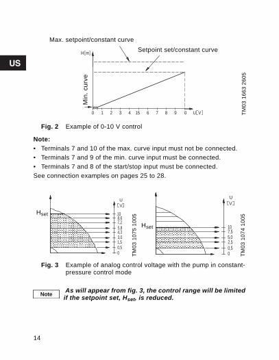
Fig. 2 Example of 0-10 V control
Note:• Terminals 7 and 10 of the max. curve input must not be connected. • Terminals 7 and 9 of the min. curve input must be connected.• Terminals 7 and 8 of the start/stop input must be connected.See connection examples on pages 25 to 28.
Fig. 3 Example of analog control voltage with the pump in constant-pressure control mode
TM03
166
3 26
05
TM03
107
5 10
05
TM03
107
4 10
05
8 90 1 07654321
m
V
H
U
Max. setpoint/constant curveSetpoint set/constant curve
Min
. cur
ve
Hset 108,67,25,84,33,01,50,50
VU
Hset 107,55,02,50,50
VU
Note As will appear from fig. 3, the control range will be limited if the setpoint set, Hset, is reduced.
14
Grundfos.bk Page 15 Wednesday, September 22, 2010 8:44 PM
8. Signal relayThe function of the signal relay can be set with the R100.Possible functions:• Fault• Ready• Operation.
8.1 Fault indicationThe signal relay is activated in case of • Pump blocked• Internal fault• Undervoltage.See section 8.4 Functional diagram.When the fault disappears, the signal relay is deactivated. The fault cause is stored in the pump alarm log. The latest five faults can be called up with the R100.
Note
In case of a fault, the red indicator light on the control panel is on.See installation and operating instructions for GRUNDFOSMAGNA 32-100.
15

Grundfos.bk Page 16 Wednesday, September 22, 2010 8:44 PM
8.2 Ready indicationThe signal relay is active when the pump is in operation or ready for operation.See section 8.4 Functional diagram.
8.3 Operating indicationThe signal relay is active as long as the pump is operating. If the pump is stopped on the control panel, with the R100 or because of a fault, the signal relay is deactivated and consequently gives a signal to an external control system, e.g. a building management system. See section 8.4 Functional diagram.
8.4 Functional diagram
Setting Relay Description
Fault Pump fault
Ready In operationReady for operation
Operation In operation
– Relay inoperable
1 2 3NC NO C
1 2 3NC NO C
1 2 3NC NO C
1 32NC NO C
16
Grundfos.bk Page 17 Wednesday, September 22, 2010 8:44 PM
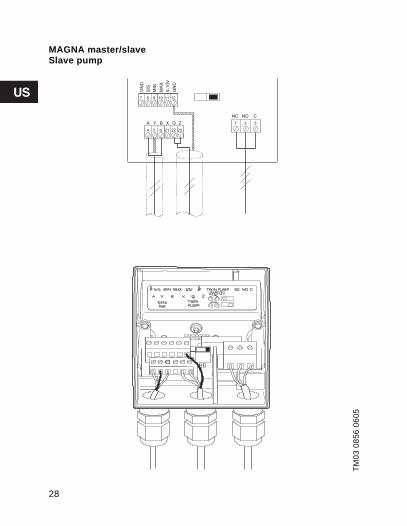
9. Control of twin-head pumpsIt is possible to connect two single-head pumps so that they operate as duty/standby. In that case, it is necessary to install non-return valves. Mount a GENI module on the control box of each pump head andconnect the modules using a cable. Both pump heads must be connected to the electricity supply.
Note
Connect a short wire between the terminals 21 "X" and 22 "Q" in the module on the right pump head, see pages 27 and 28.For the connection of the left and right pump heads, see pages 27 and 28.
17
Grundfos.bk Page 18 Wednesday, September 22, 2010 8:44 PM
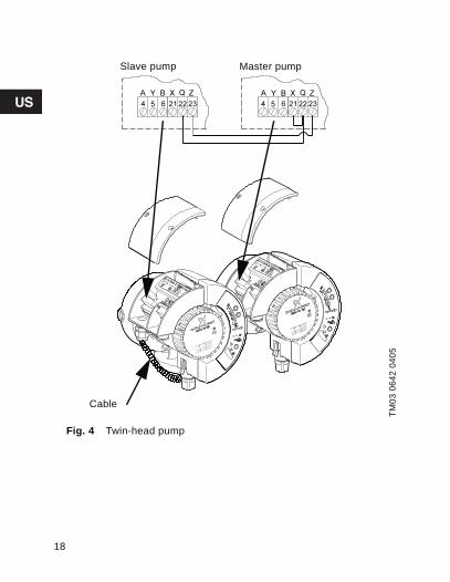
Fig. 4 Twin-head pump
TM03
064
2 04
05
Slave pump Master pump
Cable
18

Grundfos.bk Page 19 Wednesday, September 22, 2010 8:44 PM
The pump has these operating modes:• Alternating operation
Pump operation alternates every 24 hours. If the duty pump stops due to a fault, the other pump will start.
• Standby operationOne pump is operating continuously. In order to prevent seizing-up, the other pump will start at a fixed frequency. If the duty pump stops due to a fault, the other pump will start.
Select the operating mode by means of the mechanical contact in each module.
Fig. 5 Mechanical contact
Operating the pump The connected pumps can be set and operated in the same way assingle-head pumps. The duty pump uses its setpoint setting, whether it was made on the control panel, with the R100 or via bus.
Operating mode Left pump head Right pump head
Alternating Alternating Alternating
Standby Alternating Standby
Standby Standby Alternating
Standby Standby Standby
TM02
086
7 06
05Alternating operation
Standby operation
NoteBoth pumps should be set to the same setpoint and control mode. Different settings will result in different operation when changing between the two pumps.
19
Grundfos.bk Page 20 Wednesday, September 22, 2010 8:44 PM
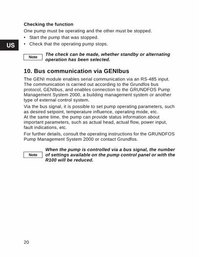
Checking the functionOne pump must be operating and the other must be stopped.• Start the pump that was stopped.• Check that the operating pump stops.
10. Bus communication via GENIbusThe GENI module enables serial communication via an RS-485 input. The communication is carried out according to the Grundfos busprotocol, GENIbus, and enables connection to the GRUNDFOS Pump Management System 2000, a building management system or another type of external control system.Via the bus signal, it is possible to set pump operating parameters, such as desired setpoint, temperature influence, operating mode, etc. At the same time, the pump can provide status information aboutimportant parameters, such as actual head, actual flow, power input, fault indications, etc. For further details, consult the operating instructions for the GRUNDFOS Pump Management System 2000 or contact Grundfos.
Note The check can be made, whether standby or alternating operation has been selected.
NoteWhen the pump is controlled via a bus signal, the number of settings available on the pump control panel or with the R100 will be reduced.
20
Grundfos.bk Page 21 Wednesday, September 22, 2010 8:44 PM
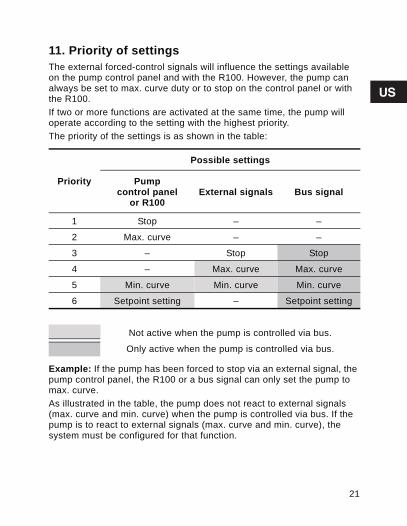
11. Priority of settingsThe external forced-control signals will influence the settings available on the pump control panel and with the R100. However, the pump can always be set to max. curve duty or to stop on the control panel or with the R100. If two or more functions are activated at the same time, the pump will operate according to the setting with the highest priority. The priority of the settings is as shown in the table:
Example: If the pump has been forced to stop via an external signal, the pump control panel, the R100 or a bus signal can only set the pump to max. curve.As illustrated in the table, the pump does not react to external signals (max. curve and min. curve) when the pump is controlled via bus. If the pump is to react to external signals (max. curve and min. curve), thesystem must be configured for that function.
Priority
Possible settings
Pump control panel
or R100 External signals Bus signal
1 Stop – –
2 Max. curve – –
3 – Stop Stop
4 – Max. curve Max. curve
5 Min. curve Min. curve Min. curve
6 Setpoint setting – Setpoint setting
Not active when the pump is controlled via bus.
Only active when the pump is controlled via bus.
21

Grundfos.bk Page 22 Wednesday, September 22, 2010 8:44 PM
12. Fault finding chart
Before starting any work on the module, make sure that the electricity supply to the pump and the module has been switched off and that it cannot be accidentally switched on.
Fault Cause Remedy
The pump does not react to the input start/stop, MIN, MAX or 10 V.
The wires are notconnected correctly to the terminal block.
Connect the wirescorrectly.
The pump was stopped on the control panel or with the R100.
Set the pump back to normal duty.
GENI module not mounted correctly. GENI module defective.Control box defective.
Mount the GENImodule correctly. Replace the GENI module. Replace the control box.
The pump does not send the correct signal from the sig-nal relay.
The wires are notconnected correctly to the terminal block.
Connect the wirescorrectly.
Signal relay notconfigured correctly.
Configure the signal relay correctly.The R100 can be used.
GENI module not mounted correctly. GENI module defective.Control box defective.
Mount the GENImodule correctly. Replace the GENI module. Replace the control box.
22

Grundfos.bk Page 23 Wednesday, September 22, 2010 8:44 PM
12.1 Checking the module
The pump does not react to theGENIbus signal.
The wires are notconnected correctly to the terminal block.
Connect the wirescorrectly.
The pump was stopped on the control panel or with the R100.
Set the pump back to normal duty.
GENI module not mounted correctly. GENI module defective.Control box defective.
Mount the GENImodule correctly. Replace the GENI module. Replace the control box.
Fault Cause Remedy
Illustration ActionTM
03 0
892
0705
1. Remove themodule cover.
2. Check the LEDs.When the pump is switched on and the module iscorrectly mounted, the left LED must be flashing and the right LED must be permanently on.
3. Refit the module cover.
FlashingPermanently on
Subject to alterations.
23
Grundfos.bk Page 24 Wednesday, September 22, 2010 8:44 PM
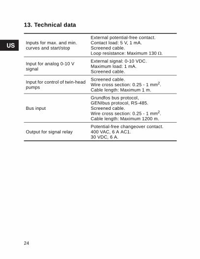
13. Technical data
Inputs for max. and min. curves and start/stop
External potential-free contact.Contact load: 5 V, 1 mA.Screened cable.Loop resistance: Maximum 130 Ω.
Input for analog 0-10 Vsignal
External signal: 0-10 VDC.Maximum load: 1 mA.Screened cable.
Input for control of twin-head pumps
Screened cable.Wire cross section: 0.25 - 1 mm2.Cable length: Maximum 1 m.
Bus input
Grundfos bus protocol,GENIbus protocol, RS-485.Screened cable.Wire cross section: 0.25 - 1 mm2.Cable length: Maximum 1200 m.
Output for signal relay Potential-free changeover contact.400 VAC, 6 A AC1.30 VDC, 6 A.
24
Grundfos.bk Page 25 Wednesday, September 22, 2010 8:44 PM
Connection example
TM03
059
1 03
05
25
Grundfos.bk Page 26 Wednesday, September 22, 2010 8:44 PM
Connection example
TM03
085
5 06
05
26

Grundfos.bk Page 27 Wednesday, September 22, 2010 8:44 PM
MAGNA master/slaveMaster pump
TM03
085
7 06
05
27
Grundfos.bk Page 28 Wednesday, September 22, 2010 8:44 PM
MAGNA master/slaveSlave pump
TM03
085
6 06
05
28

Grundfos.bk Page 39 Wednesday, September 22, 2010 8:44 PM
U.S.A.GRUNDFOS Pumps 17100 West 118th TerraceOlathe, Kansas 66061Phone: +1-913-227-3400 Fax: +1-913-227-3500
CanadaGRUNDFOS Canada Inc. 2941 Brighton Road Oakville, Ontario L6H 6C9 Phone: +1-905-829-9533 Fax: +1-905-829-9512
MéxicoBombas GRUNDFOS de México S.A. de C.V. Boulevard TLC No. 15Parque Industrial Stiva AeropuertoApodaca, N.L.C.P. 66600Phone: +52-81-8144-4000 Fax: +52-81-8144-4010
Addresses revised 22.09.2005

Grundfos.bk Page 40 Wednesday, September 22, 2010 8:44 PM

Grundfos.bk Page 41 Wednesday, September 22, 2010 8:44 PM

L-MAG-TL-04 0910
97758318 0910 US© 2009-2010 Grundfos Pumps Corp.
www.grundfos.com
The name Grundfos, the Grundfos logo, and the payoff Be–Think–Innovate are registrated trademarks owned by Grundfos Management A/S or Grundfos A/S, Denmark. All rights reserved worldwide.
Being responsible is our foundationThinking ahead makes it possible
Innovation is the essence
Grundfos.bk Page 40 Wednesday, September 22, 2010 8:44 PM