grp sectional cold water storage tanks...sectional tank. manual. grp sectional cold water storage...
TRANSCRIPT

Sectional TankManual
GRP Sectional Cold Water Storage Tanks
Manufacturing Tanks Since 1973
www.tricel.ie
Consultants
101 Rev15 Oct. 19

1
Table Content
1 Introduction ......................................................................................................................................................... 2
2 Guidelines for locating water tanks .............................................................................................................. 3
2.1 General ....................................................................................................................................................... 3
2.1.1 Water tanks on top of buildings .............................................................................................. 3
2.1.2 Guiderails on tank roofs - Health & safety requirements ............................................... 3
2.1.3 Water tanks on elevated structures ......................................................................................... 3
3 Guidelines for sizing water tanks ................................................................................................................... 4
4 Guidelines for different models of tanks ..................................................................................................... 5
5 Side access hatch ............................................................................................................................................... 7
6 Tanks insulated and finished to Format 30 ................................................................................................. 8
7 Ball valve housing .............................................................................................................................................. 9
7.1 Ball valve housing specification ........................................................................................................ 10
8 Condensation tray ........................................................................................................................................... 11
9 Tank divisions ................................................................................................................................................. 12
9.1 Maintenance on tanks with dividers ................................................................................................ 12
10 Pipe Connections for cold water storage tanks ................................................................................. 12
10.1 Pipe connections for insulated cold water storage tanks. .......................................... 14
11 Base details/design considerations ................................................................................................... 15
11.1 Internally flanged base tank ............................................................................................................ 15
11.2 Externally flanged base tank ........................................................................................................... 16
11.3 T.I.F Tanks (Hot Press and HLU) .......................................................................................................... 17
12 Capacity table ............................................................................................................................................. 18
13 Commissioning of sectional water storage tanks. .................................................................... 20
14 Maintenance recommendations for sectional water storage tanks .................................. 21
15 Guidelines for tender specification ................................................................................................ 24
16 One piece tanks .......................................................................................................................................... 25
17 Maintenance recommendations for one piece water storage tanks ............................................. 26
18 Modular building systems – Tank & equipment enclosures ........................................................... 27
19 Glossary of terms ....................................................................................................................................... 28
2
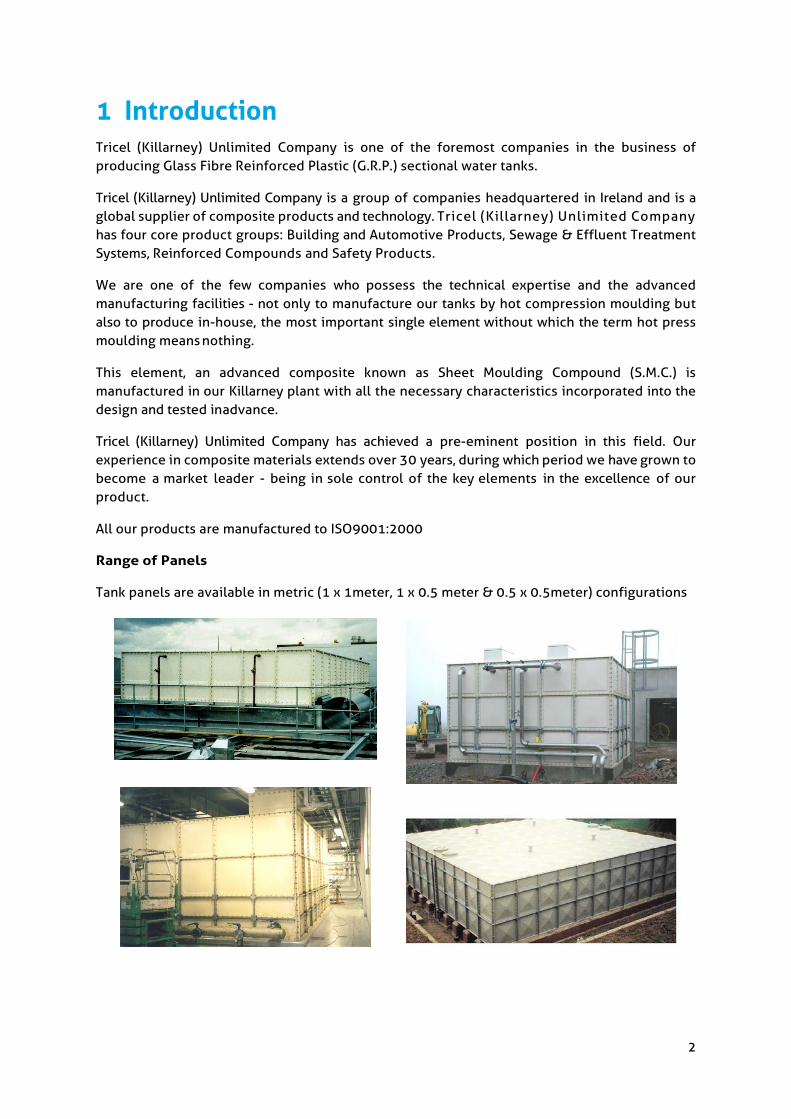
1 Introduction Tricel (Killarney) Unlimited Company is one of the foremost companies in the business of producing Glass Fibre Reinforced Plastic (G.R.P.) sectional water tanks.
Tricel (Killarney) Unlimited Company is a group of companies headquartered in Ireland and is a global supplier of composite products and technology. Tricel (Killarney) Unlimited Company has four core product groups: Building and Automotive Products, Sewage & Effluent Treatment Systems, Reinforced Compounds and Safety Products.
We are one of the few companies who possess the technical expertise and the advanced manufacturing facilities - not only to manufacture our tanks by hot compression moulding but also to produce in-house, the most important single element without which the term hot press moulding means nothing.
This element, an advanced composite known as Sheet Moulding Compound (S.M.C.) is manufactured in our Killarney plant with all the necessary characteristics incorporated into the design and tested in advance.
Tricel (Killarney) Unlimited Company has achieved a pre-eminent position in this field. Our experience in composite materials extends over 30 years, during which period we have grown to become a market leader - being in sole control of the key elements in the excellence of our product.
All our products are manufactured to ISO9001:2000
Range of Panels
Tank panels are available in metric (1 x 1meter, 1 x 0.5 meter & 0.5 x 0.5meter) configurations

3
2 Guidelines for locating water tanks
2.1 General
The following recommendations are generally for elevated tanks, as tanks at elevated positions can cause serious damage to the surrounding area in the event of wall, pipe or structural support failure resulting in water spilling out at a fast rate. Consideration must be given to minimise the effects of such an occurrence, in terms of the positioning of the tank and regular inspections.
• Water tanks should be located so as to prevent water damage or consequential loss in the event of leakage howsoever occurring.
• All tanks which are located above water sensitive areas should have a bund wall around them with adequate evacuation ducts.
• All other tanks should have plumbed Condensation or Drip trays to prevent nuisance damage and to keep floors dry.
Problems may arise with the tanks due to failure of the structural supports underneath the tanks, contaminated water attacking the internal fittings, ball valve failure where overflows were not fitted, vandalism etc.
2.1.1 Water tanks on top of buildings Water tanks located on top of any building should be sited at least 1.2 meters away from the edge of the building.
It would be preferable if the water tank was sited 1.5 times the height of the tank away from the edge of the building. In the event of failure, this would allow the water to spread itself over a much wider area before spilling over the edge of the building and possibly taking personnel or debris with it.
2.1.2 Guiderails on tank roofs - Health & safety requirements Guiderails may be necessary to satisfy Health & Safety Regulations. The type of railing required is dependant on the tank height, distance from ground level, access etc. Please confirm which guiderail arrangement is required so that we can make the necessary inclusion. We can supply and install ladders and railings, but we must be informed of the exact details prior to quoting the project. We assume that the end user is making his own arrangements unless we are informed otherwise.
2.1.3 Water tanks on elevated structures For water tanks located on top of elevated structures, a walkway of at least 1 meter should be provided around the water tank to allow for maintenance and inspection. This walkway should comply with health and safety regulations.
Potable water tanks
To comply with the Health & Safety Executive regulations on the Control of Legionellosis 1998, Cold Water Storage Tanks must be located in areas that are “readily accessible for cleaning”.
Regular Maintenance and Inspections as required by Health & Safety Legislation.

4
3 Guidelines for sizing water tanks Hotels: 1045 Litres (actual capacity) per bedroom per day
Offices: 45 Litres (actual capacity) per person per day
Schools: 36 Litres (actual capacity) per person per day
House with 2 bathrooms: 682 Litres (actual capacity) per day
The mains pressure must be sufficient to re-fill the tank while the premises are closed or in between peak time usage. In areas of low water pressure, the above figures would need to be increased. In our experience, the water pressure has been reducing gradually for the past number of years, particularly in the cities and in areas where there have been large developments.
Note: The above figures are based on Dublin Corporation guidelines. The minimum requirements do not include for fire-fighting.
Nominal versus actual capacity
Metric
Tank height (mm)
% loss in capacity for 51mm (2”) overflow
% loss in capacity for
89mm (3 ½”) overflow
500 42 51 1000 21 26 1500 14 17 2000 11 13 2500 8 10 3000 7 9 3500 6 7 4000 6 7
The above figures are approximate and are based on a 51mm (2”) and 89mm (3 ½”) overflows. If a larger overflow is used, the percentage loss will be greater. The capacity of the tank can be increased by using a ball valve housing.
15150 x 4140 x 2000mm 120,000 litre (26,000 gallons) sectional water tank insulated to Format
30. Installed 1998.

5
4 Guidelines for different models of tanks
Standard tank: This tank is complete with internally flanged base, externally flanged side walls. All under water stays are stainless steel and all external bolts are galvanised to BS EN ISO 1461:1999. Stainless steel bolts also available.
Heavy duty cover: Suitable for indoor and outdoor use, and for the storage of foul water. These tanks have internally flanged lid panels, similar to those used in the base.
Heavy duty cover and finished to Format 30: Suitable for indoor, outdoor use and for the storage of drinking water, as defined in our specification, Tricel (Killarney) Unlimited Company Format 30 on page 8.
Note:
• To comply with current legislation all tanks that store water that may be used for drinking must be protected, they must meet the requirements set out in the water byelaws
• BS EN 806 states that because any cold water tap is likely to be used to drink from, all such taps not directly connected to the mains shall be supplied only from tanks that are protected.
• Where drinking water has been stored in an inadequately protected tank, a water analysis should be considered and adequate protection installed.
• Tanks of over 1000 litres (220 gallons) shall be divided or have standby tanks to facilitate repairs and maintenance. It should also have a wash out pipe or drain out taps, these to terminate above an outside gully to prevent wastage and backflow contamination.
• Tank insulation materials should not suffer permanent structural damage from contact with water generally Phenolic and Polyurethane closed cell foams comply. Where pipe

6
cut outs go through insulation panels, bezels should be fitted to protect the exposed insulation from the ingress of moisture, insects and vermin and preserve the integrity of the insulation with a protective finish.
Types of bolts: Standard Tanks come complete with Bolts galvanised to BS EN ISO 1461:1999, we recommend that Consultants specify Stainless Steel grade 316 S16 bolts under water and on lid.
Dividers: In any situation where there is only one water storage tank in a building and the capacity is greater than 1000 litres (220 gallons), BS EN 806 states “To avoid interruption of the water supply when carrying out repairs or maintenance, the cistern shall be provided with compartments or standby cistern”. Where drinking water is being stored, two separate tanks are recommended as it is difficult to detect cross contamination from one side of a division wall to another.
Condensation trays: They should be used in any instance where condensation, drips from pipe work, or from the tank could cause nuisance damage or render floors wet and slippery.
Ball valve housing: Enclosed chamber containing an access hatch above the level of the cover, permitting the level control mechanism to be mounted at a higher level than would otherwise be possible. The overflow(s) must be placed on the tank side wall and not on the Ball Valve Housing. Water must be kept below tank roof level. This is only necessary where very large ball valves are used.
Ladders: Where tank depth is 1m or greater, internal and external ladders should be specified. If the tank is on a raised platform then ladders may be required on tanks lower than this height. Where the tank is 2m or more from the top of the tank to the finished floor level external ladders should be fitted with safety cages and comply to BS 4211:2005+A1:2008. Guiderail: A guiderail should be fitted enclosing all access points to the tank roof, where a tank is 2m or more from the top of the tank to the finished ground level. Additional safety guards maybe required for ladders depending on their location. A risk assessment should be carried out by the end users to determine if this is required.
Reverse base tanks: (Externally flanged base) These types of tanks allow the tank to be totally drained down, as the base is flat, they also allow access to all the bolts from outside the tank. 600 mm clearance is required underneath the tank for access to the base bolts.
The client shall ensure that potable water is not stored in tank compartments that are adjacent to compartments storing foul water due to risk of contamination.

7
5 Side access hatch
The Side access hatch has an opening of 600mm x 600mm. It is available as a 1000mm x 1000mm metric panel. The side access hatch is a useful choice when there are height restrictions on site. It also provides easier access to the inside of a tank, particularly when there is restricted space above the tank.
The side access hatch comprises of three main components: panel, flange and flat hatch sheet. To open the hatch, the flat hatch sheet is simply unbolted from the flange. It can only be opened when the water level inside the tank is lower than the access hatch.
This Access Hatch was designed so that both the head of the bolt and the nut are accessible. This allows a wrench to be placed on the bolt head as well as the nut and prevents a scenario of the bolt simply spinning without opening.
Please note that the ‘tank sealant’ between the flat access sheet and the will need to be in good condition or replaced, prior to the reattachment of the flat access hatch.

8
6 Tanks insulated and finished to Format 30
Note: This is an example of one type of insulation skin, there are different arrangements for different types of tanks.
• Current legislation states that water hot or cold, in any premises that might be used for human consumption must be of potable quality.
• In addition to tank material specifications, there are now further requirements for lid design, the screening of vents, breathers, overflows, warning tell-tale pipes and the provision of insulation which will help prevent freezing and also help keep water as cool as practicable, ideally less than 20oC.
• Format 30 is our description of tank with heavy duty panel covers, complete with screened vents, overflows, warning pipes etc and having side wall and roof panels with a (u) value of 2.5 w/m2K, (tanks under 1m high have a slightly higher value). This value meets the requirements of section 30 of the water bye laws in the majority of situations. Tanks in boiler rooms etc may also need base insulation. The purchaser can specify extra requirements or thermal transmittance after considering the period of protection necessary, the tank location and the surrounding conditions. Please Note: Insulation slows down but does not prevent heat loss or gain over protracted periods. Additional information is available in BS EN 13280:2001.
4150 x 4150 x 1500mm 24,000 Litre water tank insulated to F30

9
7 Ball valve housing
Note: All dimensions are in mm
Isometric view of a ball valve housing on a 4000 x 3000 x 2000 mm sectional cold water storage tank. A ball valve housing is an enclosed chamber containing an access hatch above the level of the cover, which leaves space for larger ball floats to raise up and shut off the water supply.
10
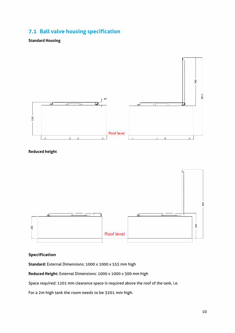
7.1 Ball valve housing specification
Standard Housing
Reduced height
Specification
Standard: External Dimensions: 1000 x 1000 x 555 mm high
Reduced Height: External Dimensions: 1000 x 1000 x 300 mm high
Space required: 1201 mm clearance space is required above the roof of the tank, i.e.
For a 2m high tank the room needs to be 3201 mm high.

11
For tanks with roof height restrictions a lift off lid is also available*
Note: The overflow(s) must be placed on the tank side wall and not on the ball valve housing. Water must be kept below tank roof level.
*Site assessment by end user needs to be completed, as adequate access is required to tank for maintenance. Refer to Base Details on page 15 for access guidelines.
8 Condensation tray We manufacture condensation trays to suit all sizes of water storage tanks. Condensation trays should be used in any instance where condensation, drips from pipe work or from the tank could cause nuisance damage or render floors wet and slippery.
For sectional cold water storage tanks, the tray extends round the tank by 150 mm. i.e. a sectional tank with dimensions 4000mm x 3000mm will have a tray approximately 4300 x 3300 mm.
Trays for large sectional tanks are joined on site.
Condensation trays should be water tested at time of testing tank.
A condensation tray is not a substitute for a bund wall or for tanking out a room.
APPROPRIATE OVERFLOWS MUST BE FITTED AS CLOSE AS POSSIBLE TO THE BASE OF THE DRIP TRAY. THESE MUST BE FITTED BEFORE THE TANK IS FILLED. TRAYS ARE DESIGNED TO HOLD A MAXIMUM OF 25MM OF WATER.

12
9 Tank divisions In any situation where there is only one water storage tank in a building and the capacity is greater than 1000 litres (220 gallons), BS EN806, states “To avoid interruption of the water supply when carrying out repairs or maintenance, the cistern shall be provided with compartments or standby cistern”. Where drinking water is being stored, two separate tanks are recommended as it is difficult detect cross contamination from one side of a division wall to another.
Offset and 50:50 division options are available. We can also supply weirs and baffles if required.
9.1 Maintenance on tanks with dividers
Extra care should be tank during the maintenance of tanks with divisions as maintenance staff will be working in an enclosed space, adjacent to a large volume of water in relation to the size of the space. (See Health & Safety Act)
10 Pipe Connections for cold water storage tanks • If the tank is to be drained down at a fast rate or by pumps etc, we should be contacted so
that adequate vents can be place on the tank. The standard vent is 2” • Connections of 100mm (4”) nominal bore or over require studded flange pads to suit BS
10:2009, table D&E flanges for pipework connections • Connections below 100mm (4”) nominal bore may be made by cutting holes in situ. First
determine whether single or double-sided connections are required and cut hole in panel to suit external pipe diameter.
• For connections over 50mm (2”) nominal bore use two flanges screwed BS21 taper thread, drilled to BS10. Offer one flange to panel concentric with hole and transfer drill bolt holes into panel. Set one flange to external pipe and using appropriate gasket, assemble external flanged pipe using other flange as an internal backing plate. Finally bolt up.
• For double sides connections proceed as above, replacing internal flange with the required fitting, e.g. ball valve, strainer basket etc.
• For connections of 50mm (2”) nominal bore or less proceed as above or alternatively use threaded flanges or backnuts (with rubber gaskets) on standard longscrew to BS1387.
Table 3, shows holes diameter for in situ pipe fitting and minimum dimensions for the location of connections from panel edges.

13
Nominal bore diameter (mm/inch)
Nominal hole size(mm/inch)
Dimension A (mm/inch)
12.7 ( ½) 22 156 (6 ¼)
19 28 (1 31/32) 161 (6 ⅜)
25.4 (1) 35 (1 ⅜) 167 (6 ⅝)
31.7 (1 ¼) 44 (1 31/32) 170 (6 ¾)
38.1 (1 ½) 50 (1 31/32) 177 (7)
50.8 (2) 61 (2 13/32) 186 (7 ⅜)
63.5 (2 ½) 78 (3 1/16) 193 (⅝)
76.2 (3) 90 (3 9/16) 202 (8)
89 105 (4⅛) 212 (8 ⅜) Table:3
General notes
All pipe work must be self-supporting. If welded or brazed-on flanges are used, all heat must be dissipated before connections are made to the tank. Holes may be cut with normal metal working tools.
Note: These figures only apply to un-insulated tanks

14
10.1 Pipe connections for insulated cold water storage tanks.
The areas where pipe connections can be made on insulated tanks are more restricted than in standard tanks, the picture below shows a recess in the insulation panel to allow for the pipe connection. Standard insulated tanks come with three insulation panels with recesses. More can be supplied if required. These are generally 190mm diameter. Large recesses are available if required.

15
11 Base details/design considerations
11.1 Internally flanged base tank
Tanks based on 1m x 1m & 1m x .5m panels
Standard base tanks (internally flanged) may be laid directly on a concrete plinth having a smooth finish, brushed clean and free from any local protuberances. It should be flat, level and not vary more than 6mm in any 6m, measured laterally or diagonally with a maximum variance of 2mm per metre. The plinth must exceed the nominal tank dimensions by a minimum of 200mm
Tanks erected on elevated structures RSJ beams or brick courses in one direction only). Bearers must be at 500mm or 1m centres depending on tank design. Bearer length must exceed nominal tank dimensions by a minimum of 150mm plus any extra for fixings. All bearer walls to be flat and level. For bearer width see chart below
Typical tank room (plan)
For dimension ‘A’ see chart below. This clearance should be on all sides of the tank, also a top clearance of 750* mm is required for standard access hatch to open.
Where hooped external ladder(s) and guardrail are fitted, a height clearance of 1200mm above the tank is required. If the tank is pushed closer to any wall after assembly or if the working space is reduced (dimension ‘A’) at a later stage, by the building of walls etc, responsibility will rest with others. *This can be reduced to 500mm in accordance with WRAS guidelines where a lift off access hatch is fitted. We must be notified of this prior to tank despatch.
Example: Tank 2650 x 1650mm
General notes: 1. Client to design suitable bearers to suit load conditions. Water load = 1000 kg/m3 + 20 % for tank.
2. Bearers can run in either direction.
3. Deflection must not exceed 1/500th of the unsupported span of the bearers. The unsupported span can only be in one direction.
4. Adequate overflows should be fitted to prevent the tank from being pressurised.
5. Tanks in exposed places may be susceptible to movement in high winds, especially when empty. These may need to be anchored to the base, this work is to be carried out by others.
6. Weight of the tank does not include the weight of the tank supports.
Working space and bearer width. Tank height mm Minimum Working space “A” mm Bearer Width “B” mm
500 500 75 1000 500 100 1500 500 100 2000 500 150 2500 800 150 3000 800 150 3500 1000 150 4000 1000 150

16
11.2 Externally flanged base tank
Tanks based on 1m x 1m & 1m x .5m panels
Externally flanged base tanks must be erected on elevated structures RSJ beams or brick courses (in one direction only). A clearance space of 600mm is required below the tank in accordance with BSEN806.
Tanks erected on bearers must be at 500mm or 1m centres depending on tank design. Bearer length must exceed nominal tank dimensions by a minimum of 150mm plus any extra for fixings. All bearer walls to be flat and level. For bearer width see chart below.
Typical tank room (plan)
For dimension ‘A’ see chart below. This clearance should be on all sides of the tank.
A top clearance of 750* mm is required for standard access hatch to open.
Where hooped external ladder(s) and guardrail are fitted, a height clearance of 1200mm above the tank is required. If the tank is pushed closer to any wall after assembly or if the working space is reduced (dimension ‘A’) at a later stage, by the building of walls etc, responsibility will rest with others.
*This can be reduced to 500mm in accordance with WRAS guidelines where a lift off access hatch is fitted. We must be notified of this prior to tank despatch.
Example: Tank 2650 x 1650mm
General notes:
1. Client to design suitable bearers to suit load conditions. Water load = 1000 kg/m3 + 20 % for tank.
2. Bearers can run in either direction.
3. Deflection must not exceed 1/500th of the unsupported span of the bearers. The unsupported span can only be in one direction.
4. Adequate overflows should be fitted to prevent the tank from being pressurised.
5. Tanks in exposed places may be susceptible to movement in high winds, especially when empty. These may need to be anchored to the base, this work is to be carried out by others.
6. Weight of the tank does not include the weight of the tank supports.
Working space and bearer width. Tank height mm Minimum Working space “A” mm Bearer Width “B” mm
500 500 75 1000 500 100 1500 500 100 2000 800 150 2500 800 150 3000 1000 150 3500 1000 150 4000 1000 150
Clearance figures shown above must be provided from internal tank dimension

17
11.3 T.I.F Tanks (Hot Press and HLU)
Tanks based on 1m x 1m & 1m x .5m panels
HLU - TIF Hotpress TIF
T.I.F tanks may be laid directly on a concrete plinth having a smooth finish, brushed clean and free from any local protuberances. It should be flat, level and not vary more than 6mm in any 6m, measured laterally or diagonally with a maximum variance of 2mm per metre.
Tanks erected on elevated structures RSJ beams or brick courses in one direction only). Bearers must be at 500mm or 1m centres depending on tank design. All bearer walls to be flat and level. For bearer width see chart below.
Typical tank room (plan)
For dimension ‘A’ & ‘B’ see chart below. A top clearance of 750* mm is required for standard access hatch to open.
Where hooped external ladder(s) and guardrail are fitted, a height clearance of 1200mm above the tank is required.
*This can be reduced to 500mm in accordance with WRAS guidelines where a lift off access hatch is fitted. We must be notified of this prior to tank despatch.
Example: Tank 2650 x 1650mm
General notes:
1. Client to design suitable bearers to suit load conditions. Water load = 1000 kg/m3 + 20 % for tank.
2. Bearers can run in either direction.
3. Deflection must not exceed 1/500th of the unsupported span of the bearers. The unsupported span can only be in one direction.
4. Adequate overflows should be fitted to prevent the tank from being pressurised.
5. Tanks in exposed places may be susceptible to movement in high winds, especially when empty. These may need to be anchored to the base, this work is to be carried out by others.
6. Weight of the tank does not include the weight of the tank supports.
Working space and bearer width. Tank height mm Minimum Working space “A”
mm Minimum Working space “B”
mm Bearer Width “B” mm
500 50 500 75 1000 50 500 100 1500 50 500 100 2000 50 500 150 2500 50 500 150 3000 50 500 150 3500 50 500 150 4000 50 500 150
Clearance figures shown above must be provided from external tank dimension
18
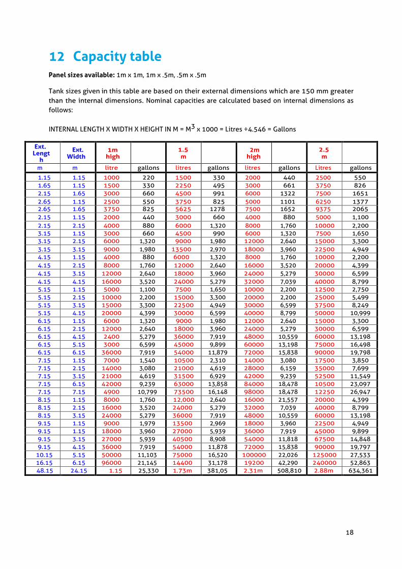
12 Capacity table Panel sizes available: 1m x 1m, 1m x .5m, .5m x .5m Tank sizes given in this table are based on their external dimensions which are 150 mm greater than the internal dimensions. Nominal capacities are calculated based on internal dimensions as follows:
INTERNAL LENGTH X WIDTH X HEIGHT IN M = M3 x 1000 = Litres ÷4.546 = Gallons
Ext. Lengt
h
Ext. Width
1m high 1.5
m 2m high 2.5
m
m m litre gallons litres gallons litres gallons Litres gallons
1.15 1.15 1000 220 1500 330 2000 440 2500 550 1.65 1.15 1500 330 2250 495 3000 661 3750 826 2.15 1.65 3000 660 4500 991 6000 1322 7500 1651 2.65 1.15 2500 550 3750 825 5000 1101 6250 1377 2.65 1.65 3750 825 5625 1278 7500 1652 9375 2065 2.15 1.15 2000 440 3000 660 4000 880 5000 1,100 2.15 2.15 4000 880 6000 1,320 8000 1,760 10000 2,200 3.15 1.15 3000 660 4500 990 6000 1,320 7500 1,650 3.15 2.15 6000 1,320 9000 1,980 12000 2,640 15000 3,300 3.15 3.15 9000 1,980 13500 2,970 18000 3,960 22500 4,949 4.15 1.15 4000 880 6000 1,320 8000 1,760 10000 2,200 4.15 2.15 8000 1,760 12000 2,640 16000 3,520 20000 4,399 4.15 3.15 12000 2,640 18000 3,960 24000 5,279 30000 6,599 4.15 4.15 16000 3,520 24000 5,279 32000 7,039 40000 8,799 5.15 1.15 5000 1,100 7500 1,650 10000 2,200 12500 2,750 5.15 2.15 10000 2,200 15000 3,300 20000 2,200 25000 5,499 5.15 3.15 15000 3,300 22500 4,949 30000 6,599 37500 8,249 5.15 4.15 20000 4,399 30000 6,599 40000 8,799 50000 10,999 6.15 1.15 6000 1,320 9000 1,980 12000 2,640 15000 3,300 6.15 2.15 12000 2,640 18000 3,960 24000 5,279 30000 6,599 6.15 4.15 2400 5,279 36000 7,919 48000 10,559 60000 13,198 6.15 5.15 3000 6,599 45000 9,899 60000 13,198 75000 16,498 6.15 6.15 36000 7,919 54000 11,879 72000 15,838 90000 19,798 7.15 1.15 7000 1,540 10500 2,310 14000 3,080 17500 3,850 7.15 2.15 14000 3,080 21000 4,619 28000 6,159 35000 7,699 7.15 3.15 21000 4,619 31500 6,929 42000 9,239 52500 11,549 7.15 6.15 42000 9,239 63000 13,858 84000 18,478 10500 23,097 7.15 7.15 4900 10,799 73500 16,148 98000 18,478 12250 26,947 8.15 1.15 8000 1,760 12,000 2,640 16000 21,557 20000 4,399 8.15 2.15 16000 3,520 24000 5,279 32000 7,039 40000 8,799 8.15 3.15 24000 5,279 36000 7,919 48000 10,559 60000 13,198 9.15 1.15 9000 1,979 13500 2,969 18000 3,960 22500 4,949 9.15 1.15 18000 3,960 27000 5,939 36000 7,919 45000 9,899 9.15 3.15 27000 5,939 40500 8,908 54000 11,818 67500 14,848 9.15 4.15 36000 7,919 54000 11,878 72000 15,838 90000 19,797
10.15 5.15 50000 11,103 75000 16,520 100000 22,026 125000 27,533 16.15 6.15 96000 21,145 14400 31,178 19200 42,290 240000 52,863 48.15 24.15 1.15 25,330 1.73m 381,05 2.31m 508,810 2.88m 634,361
19
Ext Length
Ext width
3m high
3.5 m
4m high
m m litres gallons litres gallons litres gallons
1.15 1.15 3000 660 3500 770 4000 880 1.65 1.15 4500 991 5250 1,155 6000 1,320 2.15 1.65 9000 1982 10500 2,310 12000 2,640 2.65 1.15 7500 1652 8750 1,925 10000 2,200 2.65 1.65 11250 2478 13125 2,887 15000 3,300 2.15 1.15 6000 1,320 7000 1,539 8000 1,760 2.15 2.15 12000 2,640 14000 3,079 16000 3,520 3.15 1.15 9000 1,980 10500 2,310 12000 2,640 3.15 2.15 18000 3,960 21000 4,619 24000 5,279 3.15 3.15 27000 5,939 31500 6,929 36000 7,919 4.15 1.15 12000 2,640 14000 3,080 16000 3,520 4.15 2.15 24000 5,279 28000 6,159 32000 7,039 4.15 3.15 36000 7,919 42000 9,239 48000 10,559 4.15 4.15 48000 10,559 56000 12,319 64000 14,078 5.15 1.15 15000 3,300 17500 3,850 20000 4,399 5.15 2.15 30000 6,599 35000 7,699 40000 8,799 5.15 3.15 45000 9,899 52500 11,549 60000 13,198 5.15 4.15 60000 13,198 70000 15,398 80000 17,598 6.15 1.15 18000 3,960 21000 4,619 24000 5,279 6.15 2.15 36000 7,919 42000 9,239 48000 10,559 6.15 4.15 72000 15,838 84000 18,478 96000 21,117 6.15 5.15 90000 19,798 10500 23,097 120000 26,397 6.15 6.15 10800 23,757 12600 27,717 140000 31,676 7.15 1.15 21000 4,619 24500 5,389 28000 6,159 7.15 2.15 42000 9,239 49000 10,779 56000 12,319 7.15 3.15 63000 13,858 73500 16,168 84000 18,478 7.15 6.15 12600 27,717 14700 32,336 168000 36,956 7.15 7.15 14700 32,336 17150 37,725 196000 43,115 8.15 1.15 24000 5279 28000 6,159 32000 7,039 8.15 2.15 48000 10559 56000 12,319 64000 14,078 8.15 3.15 72000 15838 84000 18,478 96000 21,117 9.15 1.15 36000 7,919 31500 6,929 36000 7,919 9.15 2.15 54000 11,878 63000 13,858 72000 15,838 9.15 3.15 81000 17,817 94500 20,788 108000 23,757 9.15 4.15 10800 23,571 12600 27,717 144000 31,676
10.15 5.15 15000 33,039 17500 38,495 200000 43,995 16.15 6.15 28800 63,436 33600 73,911 384000 84,470 48.15 24.15 3.45 m 759,91 4.03m 886,93 4.6m 1.1m
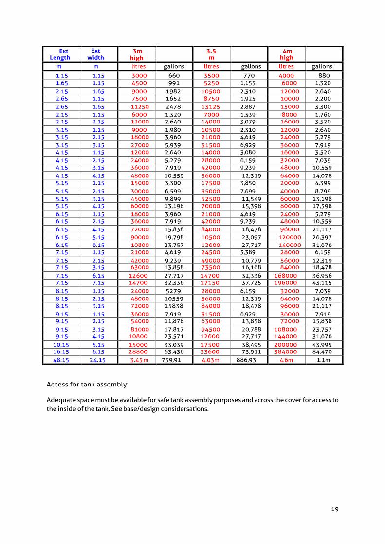
Access for tank assembly:
Adequate space must be available for safe tank assembly purposes and across the cover for access to the inside of the tank. See base/design considersations.

20
13 Commissioning of sectional water storage tanks.
Tanks should not be left unattended during commissioning.
Sectional water tanks should be filled within 14 days of end of build
1. Ensure that if there is a drip tray present that it has a functioning overflow to ensure no water ingress onto surrounding area. Appropriate overflows must be fitted to the condensation tray before the tank is filled.
2. Ensure that an appropriately sized overflow and warning pipe if required, are connected to the tank such that, if activated, they would discharge to waste in a way that would prevent any damage to the surrounding area.
3. Start filling the tank to operational level. Monitor fill to ensure there are no weeps. If minor weeps are present (and it does not cause nuisance to surrounding areas), leave tank settle for a couple of days and the weep may self-rectify. If weep does not stop, contact the office for further assistance.
4. If a major leak occurs, shut off the water, drain down the tank and contact the office for further assistance.
Commissioning Sectional water tanks after 14 days of end of build, or lying empty for several weeks or months.
1. If the tank is not commissioned within the 14 day period outlined above, of it the tank is decommissioned for a long period of time, you may need to re-torque the bolts to prevent minor weeps.
2. We recommend the tank is filled within 14 days after build and kept full of water (except for cleaning/maintenance) throughout its operating lifespan.
In the event of draining down the water tank for maintenance, cleaning or other purposes, ensure that it is refilled within a 14 days period detailed in the above commissioning information.
Where water tanks are exposed to temperature >35oC, the tank should be refilled within 2 days.

21
14 Maintenance recommendations for sectional water storage tanks
In accordance with the “The control of legionella bacteria in water systems. Approved Code of Practice and guidance” (L8) - 2000, (see Appendix I) if there is a reasonable, foreseeable risk of exposure to legionella bacteria then water tank temperatures need to be taken by competently trained personnel, recorded in a logbook and kept for 5 years.
Do not stand on internal stays while maintenance is being carried out. Minimum maintenance interval: Annually or as required by site specific risk assessment
Maintenance advice extracted from BS EN806-5:2012, 13.1 - Cisterns
Cisterns, as points of debris collection and subsequent contamination, should be inspected to ensure that overflow and warning pipes are un obstructed, that covers are not airtight but exclude light and insects and are securely fixed, and that there are no signs of leakage or deterioration likely to result in leakage. Cisterns storing water should be inspected annually or more frequently if fouling is suspected. Cleaning and disinfection should take place annually or sooner if monitoring indicated deterioration in aesthetic or microbiological quality.
Overflow and warning pipes should be checked at least annually to ensure that they confirm to 4.3.13. Cisterns should have all debris removed and they should be emptied, cleaned and disinfected. Where drinking water has been stored in an inadequately protected cistern, microbiological testing should be carried out (see 6.1.4) and adequate protection installed.
In cistern installation, a check should be made for stagnant water. If stagnant water is found, the cistern(s) should be flushed and the flow configuration modified so that the flow displaces the whole of the contents continually when the cistern is in routine use. This check should be made by assessing the stored water age and carrying out microbiological analysis together with checks on the concentration of residual disinfection. Stagnation in cisterns occurs if the residual disinfection at any point in the system is below the value defined as the minimum recommended to prevent then formation of microbiological regrowth.
Measures should be taken in accordance with 4.3.32.2 to prevent the colonization of the system with Legionella and Pseudomonas bacteria.
Further guidelines
3. In accordance with the “The control of Legionella bacteria in water systems. Approved Code of Practice and Guidance” (L8) – 2000, (see Appendix). If there is a reasonably foreseeable risk of exposure to legionella bacteria then water tank temperatures need to be taken by competently trained personnel, recorded in a logbook and kept for 5 years.
4. Do not stand on internal stays while maintenance is being carried out.
5. All internal supports should be checked for corrosion, if corrosion is found it should be rectified immediately.
6. Check generally for leaks or drips. If there a weep from a bolt or the seal, if may rectified

22
by tightening the bolts in a systematic order to a torque of 40Nm/30ft lb. Only calibrated torque should be used for this task. If the leak is at an external flange, torque the bolts around the leak. Start four bolts away from the leak, work over to the leak and then go to the fourth bolt on the opposite side and torque back to the leak. If the leak is at a joint between four panels, this procedure will be repeated in the opposite direction i.e. torque the vertical flange first and then the horizontal.
7. Check that all pipe work connected to the tank is suitably braced.
8. Check ball valve armature pins for corrosion.
9. When cleaning the inside of the tank, do not interfere with the joint seals.
10. When cleaning the tank do not overfill or pressurize the tank.
11. Check that overflows are fitted and sized correctly. Check the overflow(s) and the air inlet screens vent(s). Ensure that they are not blocked. The overflow should be twice the size of the cross-section area of the inlet
12. If insulated check that insulation and the manhole is securely fixed and not damaged, if they are damaged then the tank is not in compliance with Byelaw 30.
13. If not insulated in accordance with Byelaw 30, ensure that people cannot consume water from the tank. We can advise on upgrading the tank to Byelaw 30 standard.
14. If there is a condensation tray with the tank, ensure that it has an overflow fitted and that it is not damaged.
15. If there are ladders fitted to the tank, ensure that they have not been damaged and are securely fastened to the tank.
16. If the area underneath / adjacent to the tank has become water sensitive check that the tank room is bunded with adequate escape ducts.
17. If the tank room is bunded, check that it is in good condition.
18. With tanks for drinking water, check that the water surface is clean and shiny and that the water doesn’t contain any debris or contamination.
19. Check for evidence of stagnation of the water.
20. Check for excessive build-up of sediment.
21. Check for presence of algae, biofilm.
22. Check for scaling of the tank sidewalls.
23. The cold water storage tank should be cleaned, disinfected and faults rectified, if considered necessary.
24. After maintenance of the tank is complete, ensure that the manhole seal is intact and the manhole is securely closed.

23
Maintenance on tanks with dividers Extra care should be taken during the maintenance of tanks with divisions, as maintenance staff will be working in an enclosed space, adjacent to a large volume of water in relation to the size of the space. (See Health & Safety Act) Note:
• Further information on the Health & Safety aspect, reference water quality is available in BS EN 806 & BS 8558.
• Legal. (L8) (L 8) supersedes earlier editions and guidance published with ISBNs 0118821504, 0717604519, 0717607321 (HSG70) (HSG 70) (HS G 70) entitled, 'The control of legionellosis including Legionnaires’ disease'. It also replaces guidance note environmental health 48. (GNEH48) (GNEH 48) (GN EH48) (GN EH 48) ISBN 011883939X supplemented by MISC150 (MISC 150) entitled, 'The control of legionellosis in hot and cold water systems’.
Appendix I
This approved code of practice and guidance gives practical advice on the requirements of the Health and Safety at Work etc Act 1974, and the Control of Substances Hazardous to Health 1999, concerning the risk from exposure to legionella bacteria. The Code also gives guidance on compliance with the relevant parts of the Management of Health and Safety at Work Regulations 1999. Contents: Notice of approval; Acknowledgements; Introduction; Part 1: The approved code of practice; Scope and application; Identification and assessment of the risk; Managing the risk: management responsibilities, training and competence; Preventing or controlling the risk from exposure to legionella bacteria; Record keeping; Responsibilities of manufacturers, importers, suppliers and installers; Part 2: Guidance on the control of legionella in water systems; Cooling systems; Management of cooling towers; Treatment program’s; Monitoring; Cleaning and disinfection; Hot and cold water services; Design and construction; Management of hot and cold water systems; Treatment and control program’s; General monitoring; Cleaning and disinfection; Other risk systems; Protection of personnel; Appendix 1 Recommended inspection frequencies for risk systems; Appendix 2 Action in the event of an outbreak; Glossary; References and further reading.
24
15 Guidelines for tender specification 1. The cold water tank shall be sectional, constructed from panels 1m (3.28 ft.) square using
half and quarter panels where necessary.
2. Panels shall be hot pressed from specially formulated potable water grade of Glass reinforced plastic (G.R.P.)
3. All corner angles, gussets, divider carriers and roof supports shall be from the same material.
4. All underwater and lid bolts, tie bars, joiners etc., shall be stainless steel grade 316 S16, external bolts shall be mild steel to BS 3692 and galvanised BS 4211:2005+A1:2008.
5. The lid shall be heavy duty, formed from panels as per base design, have vertical supports at each panel intersection.
6. All vents, warning pipes, overflows, shall have mesh screens of maximum 0.65mm x 0.65mm holes to protect contents.
7. The tank shall be insulated on the sides and lid. The insulation material shall be of rigid closed cell polyurethane foam, have a protective skin securely fixed and sealed to the tank panel surface using a gasket type seal. All pipe cut outs shall have bessels, securely fitted and sealed to both the outer skin and panel face. All insulation to be to Tricel (Killarney) Unlimited Company Format 30 finish or approved equal.
8. Where the tank depth is greater than 1m (or the top of the tank is more than 1m from the ground) Internal and External ladders shall be fitted in each compartment. Where the tank is 2m or more from the top of the tank to the finished floor level external ladders should be fitted with safety cages and comply to BS 4211:2005+A1:2008. Internal ladders may be constructed from GRP or stainless steel. External ladders may be constructed from Aluminium.
9. A guiderail should be fitted enclosing all access points to the tank roof, where a tank is 2m or more from the top of the tank to the finished ground level.
10. A divider shall be fitted to facilitate maintenance and repairs.
11. A side access hatch in each compartment situated on the lowest 1m x 1m panel.
12. The client shall ensure that potable water is not stored in tank compartments that are adjacent to compartments storing foul water due to risk of contamination.
13. The contractor shall ensure that the base supports conform to the tank manufacturer’s recommendations.
14. Tanks to be commissioned and maintained in accordance with BS 6700.
15. The plumber should not leave the tank unattended during commissioning (first filling with water).
16. The tank shall be manufactured to Format 30 specification by Tricel (Killarney) Unlimited Company Ph. 00353 64-6632421 or approved equal.
25
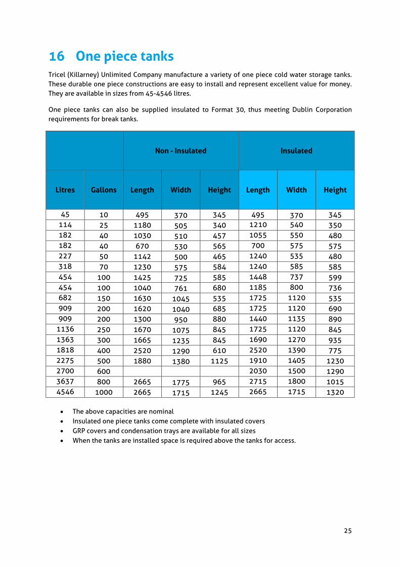
16 One piece tanks Tricel (Killarney) Unlimited Company manufacture a variety of one piece cold water storage tanks. These durable one piece constructions are easy to install and represent excellent value for money. They are available in sizes from 45-4546 litres.
One piece tanks can also be supplied insulated to Format 30, thus meeting Dublin Corporation requirements for break tanks.
Non - Insulated Insulated
Litres Gallons Length Width Height Length Width Height
45 10 495 370 345 495 370 345 114 25 1180 505 340 1210 540 350 182 40 1030 510 457 1055 550 480 182 40 670 530 565 700 575 575 227 50 1142 500 465 1240 535 480 318 70 1230 575 584 1240 585 585 454 100 1425 725 585 1448 737 599 454 100 1040 761 680 1185 800 736 682 150 1630 1045 535 1725 1120 535 909 200 1620 1040 685 1725 1120 690 909 200 1300 950 880 1440 1135 890
1136 250 1670 1075 845 1725 1120 845 1363 300 1665 1235 845 1690 1270 935 1818 400 2520 1290 610 2520 1390 775 2275 500 1880 1380 1125 1910 1405 1230 2700 600 2030 1500 1290 3637 800 2665 1775 965 2715 1800 1015 4546 1000 2665 1715 1245 2665 1715 1320
• The above capacities are nominal • Insulated one piece tanks come complete with insulated covers • GRP covers and condensation trays are available for all sizes • When the tanks are installed space is required above the tanks for access.

26
17 Maintenance recommendations for one piece water storage tanks
Maintenance interval: Minimum of once yearly.
Checklist
1. All internal supports should be checked for corrosion, if corrosion is found it should be rectified immediately.
2. Check generally for leaks of drips. 3. Check that all pipework connected to the tank is suitably braced. 4. Check that the structural supports under the tank are in good condition. 5. If overflow and/or air inlet screens are fitted, check that they have not become blocked. 6. If insulated check that the insulation and the manhole is securely fixed and not damaged, if
they are damaged then that tank is not in compliance with Bye law 30. 7. If not insulated in accordance with Byelaw 30, ensure that people cannot consume water from
the tank. We can advise upgrading the tank to Byelaw 30 standard. 8. If there is a condensation tray with the tank ensure that it has an overflow fitted and that it
has not been damaged. 9. If the tank has a light duty cover and is sited out of doors, check that the cover has not
suffered structural damage. (This type of cover is not suitable for potable water or outdoor use).
10. If the area underneath/adjacent to the tank has become water sensitive check that the tank room is bunded with adequate escape ducts.
11. If the tank room is bunded, check that it is in good condition, 12. After maintenance of the tank is complete, ensure that the manhole seal is in tact and the
manhole is securely closed.
Note: Further information on the health and safety aspect, reference water quality is available in BS EN 806 & BS 8558.

27
18 Modular building systems – Tank & equipment enclosures
The modular building system is constructed of GRP (fibreglass) modules to various sizes and colours to meet customers specifications.
Architecture.
Modular building systems can help you meet strict planning regulations, by hiding unsightly booster-sets, pumps, air- conditioning systems & water tanks. These modular systems from Tricel (Killarney) Unlimited Company can help blend roof-tops into a more natural surroundings.
External Finish.
The external finish is a light, easy to clean, horizontal ribbing. All Gelcoats are UV stabilised and may be chosen from most colours in the BS5252 or Ral ranges. Our systems are available in a range of 1000mm and 1200mm modules, with special modules to suit customer requirements.
Fire Resistance.
Fire resistance materials to Class O, Class 1 or Class 2 can be offered as an option.

28
19 Glossary of terms Sectional tank: Rectangular fixed container assembled from panels for the storage of water at
atmospheric pressure and at a maximum temperature of 30oC.
Note: This temperature is higher than is acceptable for drinking water, which should not normally
exceed 20oC.
Nominal capacity: Volume contained in a tank, measured up to the top edge of the side walls.
Actual capacity: Volume contained in the tank up to the maximum working level, this can be between 10 and 50% less than the nominal capacity, depending on the height of the tank.
Bund wall: Structure situated underneath water tanks. It’s purpose is to protect the building from water damage. All water tanks located above areas that are water sensitive should be bunded.
Ball valve housing: Enclosed chamber containing an access hatch above the level of the cover, permitting the level control mechanism to be mounted at a higher level than would otherwise be possible.
Vent: Opening to the atmosphere to allow for the movement of air resulting from changes in the water level so that the water always remains at atmospheric pressure.
Warning pipe: Pipe so fixed that it’s outlet, whether inside or outside a building, is in a conspicuous position where the discharge of water can be readily seen.
Overflow pipe: Pipe connected to the tank to discharge any overflow therefrom.
Division plate: Construction of one or more panels within a tank which divides the tank into two separate compartments.
Note: In any situation where there is only one water storage tank in a building, it is to be recommend that a weir or a division plate be used. This will facilitate maintenance of the tank without effecting the water supply to the building.
Weir: Construction of one or more panels within a tank, which divides the tank but to less than its full depth such that the contents can spill over from one side of the weir to the other.
Baffle: Construction of one or more panels within a tank, which partially subdivides the tank in order to increase the length of the flowpath between the inlet and the outlet from the tank.
Leakage test: The duration of the test should be a minimum of 24 hours, commencing at least 2 hours after the tank has been filled. The test shall be carried out within 10 days of erection unless the manufacturer agrees to a longer period after assembly. The tank should be inspected at regular intervals and not deserted during commissioning (first filling with water). The leakage test is not carried out by Tricel (Killarney) Unlimited Company
BS EN 13280:2001. Specification for glass fibre reinforced cisterns of one-piece and sectional construction, for the storage, above ground, of cold water.

29
BS 6700:1997: Specification for design, installation, testing and maintenance of services supplying water for domestic use within building and their curtilages.
Disclaimer of liability
The material and information contained herein is for general information purposes only. You should not rely upon the material or information as a basis for making any business, legal or any other decisions.
Whilst we endeavour to keep the information up to date and correct, Tricel (Killarney) Unlimited Company makes no representations or warranties of any kind, express or implied about the completeness, accuracy, reliability, suitability or availability with respect to the information, products or services contained herein for any purpose. Any reliance you place on such material is therefore strictly at your own risk.
In accordance with Tricel(Killarney) Unlimited Company, normal policy of product development, this specification is subject to change without notice.
Note: Tricel (Killarney) Unlimited Company believe that the information contained in this brochure is accurate and is printed for information only. No warrants, express or implied, are contained therein, nor does any legal liability attach to Tricel (Killarney) Unlimited Company for any reason whatsoever. Property rights of the subject belong to Tricel (Killarney) Unlimited Company, and transfer of these rights is not granted by possession of this document. Oct 19

Tricel (Killarney) Unlimited Company, Ballyspillane Industrial Estate, Killarney, Co. Kerry, V93 X253, Ireland.
Tel: +353 (0)64 663 2421 | Email: [email protected] | www.ie.tricel.eu
In accordance with Tricel (Killarney) normal policy of product development this specification is subject to change without notice.