grounding and lightning - universiti malaysia...
TRANSCRIPT

12
-1
0-8493-1703-7/03/$0.00+$1.50© 2003 by CRC Press LLC
12
Grounding and
Lightning
1
12.1 Lightning Stroke Protection ............................................
12
-1
The Design Problem
12.2 Lightning Parameters .......................................................
12
-2
Strike Distance • Stroke Current Magnitude • Keraunic Level • Ground Flash Density • Lightning Detection Networks
12.3 Empirical Design Methods ..............................................
12
-5
Fixed Angles • Empirical Curves
12.4 The Electrogeometric Model (EGM)..............................
12
-7
Whitehead’s EGM • Recent Improvements in the EGM • Criticism of the EGM • A Revised EGM • Application of the EGM by the Rolling Sphere Method • Multiple Shielding Electrodes • Changes in Voltage Level • Minimum Stroke Current • Application of Revised EGM by Mousa and Srivastava Method
12.5 Calculation of Failure Probability.................................
12
-1812.6 Active Lightning Terminals............................................
12
-20References ..................................................................................
12
-20
12.1 Lightning Stroke Protection
Substation design involves more than installing apparatus, protective devices, and equipment. The sig-nificant monetary investment and required reliable continuous operation of the facility requires detailedattention to preventing surges (transients) from entering the substation facility. These surges can beswitching surges, lightning surges on connected transmission lines, or direct strokes to the substationfacility. The origin and mechanics of these surges, including lightning, are discussed in detail in Chapter 10of
The Electric Power Engineering Handbook
(CRC Press, 2001). This section focuses on the design processfor providing
effective
shielding
(that which permits lightning strokes no greater than those of criticalamplitude [less design margin] to reach phase conductors [IEEE Std. 998-1996]) against direct lightningstroke in substations.
1
A large portion of the text and all of the figures used in the following discussion were prepared by the DirectStroke Shielding of Substations Working Group of the Substations Committee — IEEE Power Engineering Society,and published as IEEE Std. 998-1996,
IEEE Guide for Direct Lightning Stroke Shielding of Substations,
Institute ofElectrical and Electronics Engineers, Inc., 1996. The IEEE disclaims any responsibility or liability resulting from theplacement or use in the described manner. Information is reprinted with the permission of the IEEE. The authorhas been a member of the working group since 1987.
Robert S. Nowell
Georgia Power Company
1703_Frame_C12.fm Page 1 Monday, May 12, 2003 5:50 PM
© 2003 by CRC Press LLC

12
-2
Electric Power Substations Engineering
12.1.1 The Design Problem
The engineer who seeks to design a direct stroke shielding system for a substation or facility must contendwith several elusive factors inherent in lightning phenomena, namely:
• The unpredictable, probabilistic nature of lightning• The lack of data due to the infrequency of lightning strokes in substations• The complexity and economics involved in analyzing a system in detail
There is no known method of providing 100% shielding short of enclosing the equipment in a solidmetallic enclosure. The uncertainty, complexity, and cost of performing a detailed analysis of a shieldingsystem has historically resulted in simple rules of thumb being utilized in the design of lower voltagefacilities. Extra high voltage (EHV) facilities, with their critical and more costly equipment components,usually justify a more sophisticated study to establish the risk vs. cost benefit.
Because of the above factors, it is suggested that a four-step approach be utilized in the design of aprotection system:
1. Evaluate the importance and value of the facility being protected.2. Investigate the severity and frequency of thunderstorms in the area of the substation facility and
the exposure of the substation.3. Select an appropriate design method consistent with the above evaluation and then lay out an
appropriate system of protection.4. Evaluate the effectiveness and cost of the resulting design.
The following paragraphs and references will assist the engineer in performing these steps.
12.2 Lightning Parameters
12.2.1 Strike Distance
Return stroke current magnitude and strike distance (length of the last stepped leader) are interrelated.A number of equations have been proposed for determining the striking distance. The principal onesare as follows:
(12.1)
(12.2)
(12.3)
(12.4)
(12.5)
where
S
is the strike distance in meters
I
is the return stroke current in kiloamperes
It may be disconcerting to note that the above equations vary by as much as a factor of 2:1. However,lightning investigators now tend to favor the shorter strike distances given by Equation 12.4. Anderson,for example, who adopted Equation 12.2 in the 1975 edition of the
Transmission Line Reference Book
(1987), now feels that Equation 12.4 is more accurate. Mousa (1988) also supports this form of theequation. The equation may also be stated as follows:
S I e I= + −( )−2 30 1 6 8. Darveniza (1975)
S I= ( )10 0 65. Love 1987; 1993
S I= ( )9 4 2 3. Whitehead 1974
S I= ( )8 0 65. IEEE 1985
S I= ( )3 3 0 78. . Suzuki 1981
1703_Frame_C12.fm Page 2 Monday, May 12, 2003 5:50 PM
© 2003 by CRC Press LLC

Grounding and Lightning
12
-3
(12.6)
From this point on, the return stroke current will be referenced as the
stroke current
.
12.2.2 Stroke Current Magnitude
Since the stroke current and striking distance are related, it is of interest to know the distribution ofstroke current magnitudes. The median value of strokes to OHGW, conductors, structures, and masts isusually taken to be 31 kA (Anderson, 1987). Anderson (1987) gave the probability that a certain peakcurrent will be exceeded in any stroke as follows:
(12.7)
where
P(I)
is the probability that the peak current in any stroke will exceed
II
is the specified crest current of the stroke in kiloamperes
Mousa (1989) has shown that a median stroke current of 24 kA for strokes to flat ground producesthe best correlation with available field observations to date. Using this median value of stroke current,the probability that a certain peak current will be exceeded in any stroke is given by the following equation:
(12.8)
where the symbols have the same meaning as above.Figure 12.1 is a plot of Equation 12.8, and Figure 12.2 is a plot of the probability that a stroke will be
within the ranges shown on the abscissa.
FIGURE 12.1
Probability of stroke current exceeding abscissa for strokes to flat ground. (IEEE Std. 998-1996. Withpermission.)
I S= 0 041 1 54. .
P II( ) = + ( )
1 1 312 6.
P II( ) = + ( )
1 1 242 6.
1703_Frame_C12.fm Page 3 Monday, May 12, 2003 5:50 PM
© 2003 by CRC Press LLC

12
-4
Electric Power Substations Engineering
12.2.3 Keraunic Level
Keraunic level
is defined as the average annual number of thunderstorm days or hours for a given locality.A daily keraunic level is called a thunderstorm-day and is the average number of days per year on whichthunder will be heard during a 24-h period. By this definition, it makes no difference how many timesthunder is heard during a 24-h period. In other words, if thunder is heard on any one day more thanone time, the day is still classified as one thunder-day (or thunderstorm day). The average annual kerauniclevel for locations in the U.S. can be determined by referring to isokeraunic maps on which lines of equalkeraunic level are plotted on a map of the country. Figure 12.3 gives the mean annual thunderstorm daysfor the U.S.
FIGURE 12.2
Stroke current range probability for strokes to flat ground. (IEEE Std. 998-1996. With permission.)
FIGURE 12.3
Mean annual thunderstorm days in the U.S. (IEEE Std. 998-1996. With permission.)
1703_Frame_C12.fm Page 4 Monday, May 12, 2003 5:50 PM
© 2003 by CRC Press LLC

Grounding and Lightning
12
-5
12.2.4 Ground Flash Density
Ground flash density
(GFD) is defined as the average number of strokes per unit area per unit time at aparticular location. It is usually assumed that the GFD to earth, a substation, or a transmission ordistribution line is roughly proportional to the keraunic level at the locality. If thunderstorm days are tobe used as a basis, it is suggested that the following equation be used (Anderson, 1987):
(12.9)
or
(12.10)
where
N
k
is the number of flashes to earth per square kilometer per year
N
m
is the number of flashes to earth per square mile per year
T
d
is the average annual keraunic level, thunderstorm days
12.2.5 Lightning Detection Networks
A new technology is now being deployed in Canada and the U.S. that promises to provide more accurateinformation about ground flash density and lightning stroke characteristics. Mapping of lightning flashesto the earth has been in progress for over a decade in Europe, Africa, Australia, and Asia. Now a networkof direction-finding receiving stations has been installed across Canada and the U.S. By means of trian-gulation among the stations, and with computer processing of signals, it is possible to pinpoint the locationof each lightning discharge. Hundreds of millions of strokes have been detected and plotted to date.
Ground flash density maps have already been prepared from this data, but with the variability infrequency and paths taken by thunderstorms from year to year, it will take a number of years to developdata that is statistically significant. Some electric utilities are, however, taking advantage of this technologyto detect the approach of thunderstorms and to plot the location of strikes on their system. Thisinformation is very useful for dispatching crews to trouble spots and can result in shorter outages thatresult from lightning strikes.
12.3 Empirical Design Methods
Two classical design methods have historically been employed to protect substations from direct lightningstrokes:
1. Fixed angles2. Empirical curves
The two methods have generally provided acceptable protection.
12.3.1 Fixed Angles
The fixed-angle design method uses vertical angles to determine the number, position, and height ofshielding wires or masts. Figure 12.4 illustrates the method for shielding wires, and Figure 12.5 illustratesthe method for shielding masts. The angles used are determined by the degree of lightning exposure, theimportance of the substation being protected, and the physical area occupied by the substation. The valueof the angle alpha that is commonly used is 45°. Both 30° and 45° are widely used for angle beta. (Samplecalculations for low-voltage and high-voltage substations using fixed angles are given in annex B of IEEEStd. 998-1996.)
N Tk d= 0 12.
N Tm d= 0 31.
1703_Frame_C12.fm Page 5 Monday, May 12, 2003 5:50 PM
© 2003 by CRC Press LLC

12
-6
Electric Power Substations Engineering
12.3.2 Empirical Curves
From field studies of lightning and laboratory model tests, empirical curves have been developed todetermine the number, position, and height of shielding wires and masts (Wagner et al., 1941; Wagner,1942; Wagner, McCann, Beck, 1941). The curves were developed for shielding failure rates of 0.1, 1.0,5.0, 10, and 15%. A failure rate of 0.1% is commonly used in design. Figure 12.6 and Figure 12.7 havebeen developed for a variety of protected object heights,
d
. The empirical curve method has also beenreferred to as the Wagner method.
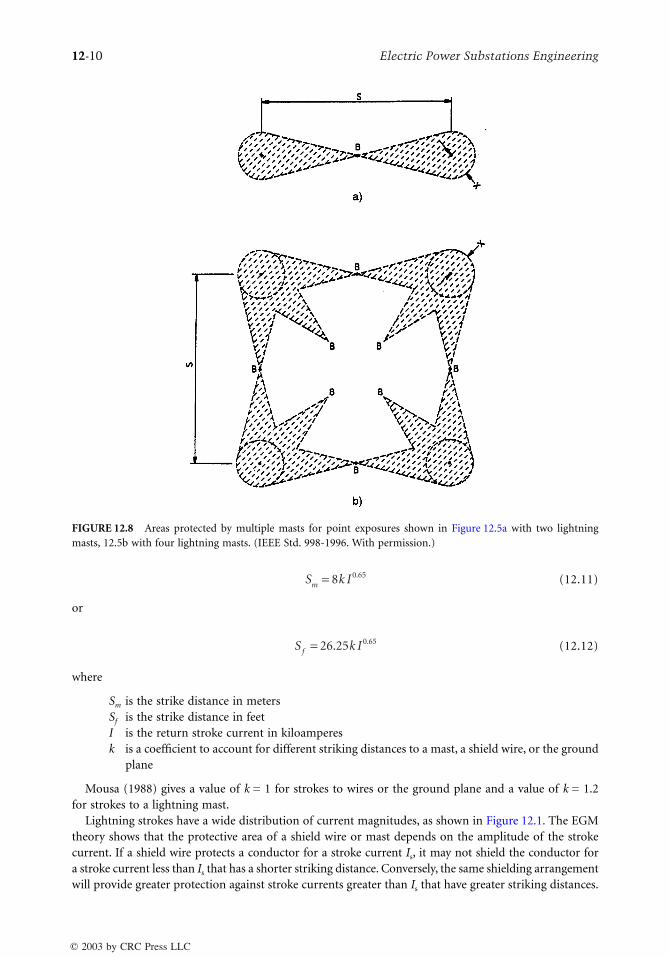
12.3.2.1 Areas Protected by Lightning Masts
Figure 12.8 and Figure 12.9 illustrate the areas that can be protected by two or more shielding masts(Wagner et al., 1942). If two masts are used to protect an area, the data derived from the empirical curvesgive shielding information only for the point
B
, midway between the two masts, and for points on thesemicircles drawn about the masts, with radius
x
, as shown in Figure 12.8a. The locus shown inFigure 12.8a, drawn by the semicircles around the masts, with radius
x
, and connecting the point
B
,represents an approximate limit for a selected exposure rate. Any single point falling within the cross-hatched area should have <0.1% exposure. Points outside the cross-hatched area will have >0.1% expo-sure. Figure 12.8b illustrates this phenomenon for four masts spaced at the distance s as in Figure 12.8a.
FIGURE 12.4
Fixed angles for shielding wires. (IEEE Std. 998-1996. With permission.)
1703_Frame_C12.fm Page 6 Monday, May 12, 2003 5:50 PM
© 2003 by CRC Press LLC

Grounding and Lightning
12
-7
The protected area can be improved by moving the masts closer together, as illustrated in Figure 12.9.In Figure 12.9a, the protected areas are, at least, as good as the combined areas obtained by superimposingthose of Figure 12.8a. In Figure 12.9a, the distance
s
′
is one half the distance
s
in Figure 12.8a. To estimatethe width of the overlap,
x
′
, first obtain a value of
y
corresponding to twice the distance
s
′
between themasts. Then use Figure 12.6 to determine
x
′
for this value of
y
. This value of
x
is used as an estimate ofthe width of overlap
x
′
in Figure 12.9. As illustrated in Figure 12.9b, the size of the areas with an exposuregreater than 0.1% has been significantly reduced. (Sample calculations for low-voltage and high-voltagesubstations using empirical curves are given in annex B of IEEE Std. 998-1996.)
12.4 The Electrogeometric Model (EGM)
Shielding systems developed using classical methods (fixed angles and empirical curves) of determiningthe necessary shielding for direct stroke protection of substations have historically provided a fair degreeof protection. However, as voltage levels (and therefore structure and conductor heights) have increasedover the years, the classical methods of shielding design have proven less adequate. This led to thedevelopment of the electrogeometric model.
FIGURE 12.5
Fixed angles for masts. (IEEE Std. 998-1996. With permission.)
1703_Frame_C12.fm Page 7 Monday, May 12, 2003 5:50 PM
© 2003 by CRC Press LLC

12
-8
Electric Power Substations Engineering
12.4.1 Whitehead’s EGM
In 1960, Anderson developed a computer program for calculation of transmission line lightning performancethat uses the
Monte Carlo Method
(1961). This method showed good correlation with actual line performance.An early version of the EGM was developed in 1963 by Young et al., but continuing research soon led to newmodels. One extremely significant research project was performed by Whitehead (1971). Whitehead’s workincluded a theoretical model of a transmission system subject to direct strokes, development of analyticalexpressions pertaining to performance of the line, and supporting field data that verified the theoreticalmodel and analyses. The final version of this model was published by Gilman and Whitehead in 1973.
12.4.2 Recent Improvements in the EGM
Sargent made an important contribution with the
Monte Carlo Simulation
of lightning performance(1972) and his work on lightning strokes to tall structures (1972). Sargent showed that the frequencydistribution of the amplitudes of strokes collected by a structure depends on the structure height as wellas on its type (mast vs. wire). In 1976, Mousa extended the application of the EGM (which was developedfor transmission lines) to substation facilities.
12.4.3 Criticism of the EGM
Work by Eriksson reported in 1978 and later work by Anderson and Eriksson reported in 1980 revealedapparent discrepancies in the EGM that tended to discredit it. Mousa (1988) has shown, however, thatexplanations do exist for the apparent discrepancies, and that many of them can be eliminated by adoptinga revised electrogeometric model. Most investigators now accept the EGM as a valid approach fordesigning lightning shielding systems.
FIGURE 12.6
Single lightning mast protecting single ring of object — 0.1% exposure. Height of mast aboveprotected object,
y
, as a function of horizontal separation,
x
, and height of protected object,
d
. (IEEE Std. 998-1996.With permission.)
1703_Frame_C12.fm Page 8 Monday, May 12, 2003 5:50 PM
© 2003 by CRC Press LLC

Grounding and Lightning
12
-9
12.4.4 A Revised EGM
The revised EGM was developed by Mousa and Srivastava (1986; 1988). Two methods of applying theEGM are the modified version of the rolling sphere method (Lee, 1979; Lee, 1978; Orell, 1988), and themethod given by Mousa and Srivastava (1988; 1991).
The revised EGM model differs from Whitehead’s model in the following respects:
1. The stroke is assumed to arrive in a vertical direction. (It has been found that Whitehead’sassumption of the stroke arriving at random angles is an unnecessary complication [Mousa andSrivastava, 1988].)
2. The differing striking distances to masts, wires, and the ground plane are taken into consideration.3. A value of 24 kA is used as the median stroke current (Mousa and Srivastava, 1989). This selection
is based on the frequency distribution of the first negative stroke to flat ground. This value bestreconciles the EGM with field observations.
4. The model is not tied to a specific form of the striking distance equations (Equation 12.1 throughEquation 12.6). Continued research is likely to result in further modification of this equation asit has in the past. The best available estimate of this parameter may be used.
12.4.4.1 Description of the Revised EGM
Previously, the concept that the final striking distance is related to the magnitude of the stroke currentwas introduced and Equation 12.4 was selected as the best approximation of this relationship. Acoefficient
k
accounts for the different striking distances to a mast, a shield wire, and to the ground.Equation 12.4 is repeated here with this modification:
FIGURE 12.7
Two lightning masts protecting single object, no overlap — 0.1% exposure. Height of mast aboveprotected object,
y
, as a function of horizontal separation,
s
, and height of protected object,
d
. (IEEE Std. 998-1996.With permission.)
1703_Frame_C12.fm Page 9 Monday, May 12, 2003 5:50 PM
© 2003 by CRC Press LLC
12
-10
Electric Power Substations Engineering
(12.11)
or
(12.12)
where
S
m
is the strike distance in meters
S
f
is the strike distance in feet
I
is the return stroke current in kiloamperes
k
is a coefficient to account for different striking distances to a mast, a shield wire, or the groundplane
Mousa (1988) gives a value of
k
= 1 for strokes to wires or the ground plane and a value of
k
= 1.2for strokes to a lightning mast.
Lightning strokes have a wide distribution of current magnitudes, as shown in Figure 12.1. The EGMtheory shows that the protective area of a shield wire or mast depends on the amplitude of the strokecurrent. If a shield wire protects a conductor for a stroke current
I
s
, it may not shield the conductor fora stroke current less than
I
s
that has a shorter striking distance. Conversely, the same shielding arrangementwill provide greater protection against stroke currents greater than
I
s
that have greater striking distances.
FIGURE 12.8 Areas protected by multiple masts for point exposures shown in Figure 12.5a with two lightningmasts, 12.5b with four lightning masts. (IEEE Std. 998-1996. With permission.)
S k Im = 8 0 65.
S k If = 26 25 0 65. .
1703_Frame_C12.fm Page 10 Monday, May 12, 2003 5:50 PM
© 2003 by CRC Press LLC

Grounding and Lightning 12-11
Since strokes less than some critical value Is can penetrate the shield system and terminate on the protectedconductor, the insulation system must be able to withstand the resulting voltages without flashover. Statedanother way, the shield system should intercept all strokes of magnitude Is and greater so that flashoverof the insulation will not occur.
12.4.4.2 Allowable Stroke Current
Some additional relationships need to be introduced before showing how the EGM is used to design azone of protection for substation equipment. Bus insulators are usually selected to withstand a basiclightning impulse level (BIL). Insulators may also be chosen according to other electrical characteristics,including negative polarity impulse critical flashover (CFO) voltage. Flashover occurs if the voltage pro-duced by the lightning stroke current flowing through the surge impedance of the station bus exceedsthe withstand value. This may be expressed by the Gilman and Whitehead equation (1973):
(12.13)
or
(12.14)
FIGURE 12.9 Areas protected by multiple masts for point exposures shown in Figure 12.5 (a) With two lightningmasts; (b) with four lightning masts. (IEEE Std. 998-1996. With permission.)
I Z ZS SS BIL 1.1 BIL= × ( ) = ( )2 2 2.
I Z ZS SS C.F.O C.F.O.= × × ( ) = ( )0 94 1 1 2 2 068. . . .
1703_Frame_C12.fm Page 11 Monday, May 12, 2003 5:50 PM
© 2003 by CRC Press LLC
12-12 Electric Power Substations Engineering
where
Is is the allowable stroke current in kiloamperesBIL is the basic lightning impulse level in kilovoltsCFO is the negative polarity critical flashover voltage of the insulation being considered in
kilovoltsZs is the surge impedance of the conductor through which the surge is passing in ohms1.1 is the factor to account for the reduction of stroke current terminating on a conductor as
compared to zero impedance earth (Gilman and Whitehead, 1973)
In Equation 12.14, the CFO has been reduced by 6% to produce a withstand level roughly equivalentto the BIL rating for post insulators.
Withstand Voltage of Insulator Strings
BIL values of station post insulators can be found in vendor catalogs. A method is given below forcalculating the withstand voltage of insulator strings. The withstand voltage in kV at 2 µs and 6 µs canbe calculated as follows:
(12.15)
(12.16)
where
w is the length of insulator string (or air gap) in meters0.94 is the ratio of withstand voltage to CFO voltageVI2 is the withstand voltage in kilovolts at 2 µsVI6 is the withstand voltage in kilovolts at 6 µs
Equation 12.16 is recommended for use with the EGM.
12.4.5 Application of the EGM by the Rolling Sphere Method
It was previously stated that it is only necessary to provide shielding for the equipment from all lightningstrokes greater than Is that would result in a flashover of the buswork. Strokes less than Is are permittedto enter the protected zone since the equipment can withstand voltages below its BIL design level. Thiswill be illustrated by considering three levels of stroke current: Is, stroke currents greater than Is, andstroke currents less than Is. First, let us consider the stroke current Is.
12.4.5.1 Protection Against Stroke Current Is
Is is calculated from Equation 12.13 or Equation 12.14 as the current producing a voltage the insulationwill just withstand. Substituting this result in Equation 12.11 or Equation 12.12 gives the striking distanceS for this stroke current. In 1977, Lee developed a simplified technique for applying the electrogeometrictheory to the shielding of buildings and industrial plants (1982; 1979; 1978). Orrell extended the techniqueto specifically cover the protection of electric substations (1988). The technique developed by Lee hascome to be known as the rolling sphere method. For the following illustration, the rolling sphere methodwill be used. This method employs the simplifying assumption that the striking distances to the ground,a mast, or a wire are the same. With this exception, the rolling sphere method has been updated inaccordance with the revised EGM.
Use of the rolling sphere method involves rolling an imaginary sphere of radius S over the surface ofa substation. The sphere rolls up and over (and is supported by) lightning masts, shield wires, substationfences, and other grounded metallic objects that can provide lightning shielding. A piece of equipmentis said to be protected from a direct stroke if it remains below the curved surface of the sphere by virtue
V wI2 0 94 820= ×.
V wI6 0 94 585= ×.
1703_Frame_C12.fm Page 12 Monday, May 12, 2003 5:50 PM
© 2003 by CRC Press LLC

Grounding and Lightning 12-13
of the sphere being elevated by shield wires or other devices. Equipment that touches the sphere orpenetrates its surface is not protected. The basic concept is illustrated in Figure 12.10.
Continuing the discussion of protection against stroke current Is, consider first a single mast. Thegeometrical model of a single substation shield mast, the ground plane, the striking distance, and thezone of protection are shown in Figure 12.11. An arc of radius S that touches the shield mast and theground plane is shown in Figure 12.11. All points below this arc are protected against the stroke currentIs. This is the protected zone. The arc is constructed as follows (see Figure 12.11). A dashed line is drawnparallel to the ground at a distance S (the striking distance as obtained from Equation 12.11 or Equation 12.12)above the ground plane. An arc of radius S, with its center located on the dashed line, is drawn so theradius of the arc just touches the mast. Stepped leaders that result in stroke current Is and that descendoutside of the point where the arc is tangent to the ground will strike the ground. Stepped leaders thatresult in stroke current Is and that descend inside the point where the arc is tangent to the ground willstrike the shield mast, provided all other objects are within the protected zone. The height of the shieldmast that will provide the maximum zone of protection for stroke currents equal to Is is S. If the mastheight is less than S, the zone of protection will be reduced. Increasing the shield mast height greater thanS will provide additional protection in the case of a single mast. This is not necessarily true in the case ofmultiple masts and shield wires. The protection zone can be visualized as the surface of a sphere withradius S that is rolled toward the mast until touching the mast. As the sphere is rolled around the mast,a three-dimensional surface of protection is defined. It is this concept that has led to the name rollingsphere for simplified applications of the electrogeometric model.
12.4.5.2 Protection Against Stroke Currents Greater than Is
A lightning stroke current has an infinite number of possible magnitudes, however, and the substationdesigner will want to know if the system provides protection at other levels of stroke current magnitude.Consider a stroke current Is1 with magnitude greater than Is. Strike distance, determined fromEquation 12.11 or Equation 12.12, is S1. The geometrical model for this condition is shown inFigure 12.12. Arcs of protection for stroke current Is1 and for the previously discussed Is are both shown.The figure shows that the zone of protection provided by the mast for stroke current Is1 is greater thanthe zone of protection provided by the mast for stroke current Is. Stepped leaders that result in strokecurrent Is1 and that descend outside of the point where the arc is tangent to the ground will strike the
FIGURE 12.10 Principle of the rolling sphere. (IEEE Std. 998-1996. With permission.)
1703_Frame_C12.fm Page 13 Monday, May 12, 2003 5:50 PM
© 2003 by CRC Press LLC

12-14 Electric Power Substations Engineering
ground. Stepped leaders that result in stroke current Is1 and that descend inside the point where the arcis tangent to the ground will strike the shield mast, provided all other objects are within the S1 protectedzone. Again, the protective zone can be visualized as the surface of a sphere touching the mast. In thiscase, the sphere has a radius S1.
12.4.5.3 Protection Against Stroke Currents Less than Is
It has been shown that a shielding system that provides protection at the stroke current level Is provideseven better protection for larger stroke currents. The remaining scenario to examine is the protectionafforded when stroke currents are less than Is. Consider a stroke current Iso with magnitude less than Is.The striking distance, determined from Equation 12.11 or Equation 12.12, is S0. The geometrical modelfor this condition is shown in Figure 12.13. Arcs of protection for stroke current Iso and Is are both shown.The figure shows that the zone of protection provided by the mast for stroke current Iso is less than thezone of protection provided by the mast for stroke current Is. It is noted that a portion of the equipmentprotrudes above the dashed arc or zone of protection for stroke current Iso. Stepped leaders that resultin stroke current Iso and that descend outside of the point where the arc is tangent to the ground willstrike the ground. However, some stepped leaders that result in stroke current Iso and that descend insidethe point where the arc is tangent to the ground could strike the equipment. This is best shown by
FIGURE 12.11 Shield mast protection for stroke current Is. (IEEE Std. 998-1996. With permission.)
1703_Frame_C12.fm Page 14 Monday, May 12, 2003 5:50 PM
© 2003 by CRC Press LLC

Grounding and Lightning 12-15
observing the plan view of protective zones shown in Figure 12.13. Stepped leaders for stroke current Iso
that descend inside the inner protective zone will strike the mast and protect equipment that is h inheight. Stepped leaders for stroke current Iso that descend in the shaded unprotected zone will strikeequipment of height h in the area. If, however, the value of Is was selected based on the withstand insulationlevel of equipment used in the substation, stroke current Iso should cause no damage to equipment.
12.4.6 Multiple Shielding Electrodes
The electrogeometric modeling concept of direct stroke protection has been demonstrated for a singleshield mast. A typical substation, however, is much more complex. It may contain several voltage levelsand may utilize a combination of shield wires and lightning masts in a three-dimensional arrangement.The above concept can be applied to multiple shielding masts, horizontal shield wires, or a combinationof the two. Figure 12.14 shows this application considering four shield masts in a multiple shield mastarrangement. The arc of protection for stroke current Is is shown for each set of masts. The dashed arcsrepresent those points at which a descending stepped leader for stroke current Is will be attracted to oneof the four masts. The protected zone between the masts is defined by an arc of radius S with the center
FIGURE 12.12 Shield mast protection for stroke current Is1. (IEEE Std. 998-1996. With permission.)
1703_Frame_C12.fm Page 15 Monday, May 12, 2003 5:50 PM
© 2003 by CRC Press LLC

12-16 Electric Power Substations Engineering
at the intersection of the two dashed arcs. The protective zone can again be visualized as the surface ofa sphere with radius S, which is rolled toward a mast until touching the mast, then rolled up and overthe mast such that it would be supported by the masts. The dashed lines would be the locus of the centerof the sphere as it is rolled across the substation surface. Using the concept of rolling a sphere of theproper radius, the protected area of an entire substation can be determined. This can be applied to anygroup of different height shield masts, shield wires, or a combination of the two. Figure 12.15 shows anapplication to a combination of masts and shield wires.
12.4.7 Changes in Voltage Level
Protection has been illustrated with the assumption of a single voltage level. Substations, however, havetwo or more voltage levels. The rolling sphere method is applied in the same manner in such cases, exceptthat the sphere radius would increase or decrease appropriate to the change in voltage at a transformer.(Sample calculations for a substation with two voltage levels are given in annex B of IEEE Std. 998-1996.)
12.4.8 Minimum Stroke Current
The designer will find that shield spacing becomes quite close at voltages of 69 kV and below. It may beappropriate to select some minimum stroke current, perhaps 2 kA for shielding stations below 115 kV.Such an approach is justified by an examination of Figure 12.1 and Figure 12.2. It will be found that
FIGURE 12.13 Shield mast protection for stroke current Is0. (IEEE Std. 998-1996. With permission.)
1703_Frame_C12.fm Page 16 Monday, May 12, 2003 5:50 PM
© 2003 by CRC Press LLC

Grounding and Lightning 12-17
99.8% of all strokes will exceed 2 kA. Therefore, this limit will result in very little exposure, but will makethe shielding system more economical.
12.4.9 Application of Revised EGM by Mousa and Srivastava Method
The rolling sphere method has been used in the preceding paragraphs to illustrate application of theEGM. Mousa describes the application of the revised EGM (1976). Figure 12.16 depicts two shield wires,Gl, and G2, providing shielding for three conductors, W1, W2, and W3. Sc is the critical striking distanceas determined by Equation 12.11, but reduced by 10% to allow for the statistical distribution of strokesso as to preclude any failures. Arcs of radius Sc are drawn with centers at G1, G2, and W2 to determine
FIGURE 12.14 Multiple shield mast protection for stroke current Is. (IEEE Std. 998-1996. With permission.)
1703_Frame_C12.fm Page 17 Monday, May 12, 2003 5:50 PM
© 2003 by CRC Press LLC

12-18 Electric Power Substations Engineering
if the shield wires are positioned to properly shield the conductors. The factor ψ is the horizontalseparation of the outer conductor and shield wire, and b is the distance of the shield wires above theconductors. Figure 12.17 illustrates the shielding provided by four masts. The height hmid at the centerof the area is the point of minimum shielding height for the arrangement. For further details in theapplication of the method, see Mousa (1976). At least two computer programs have been developed thatassist in the design of a shielding system. One of these programs (Mousa, 1991) uses the revised EGMto compute the surge impedance, stroke current, and striking distance for a given arrangement ofconductors and shield systems, then advises the user whether or not effective shielding is provided.(Sample calculations are provided in annex B of IEEE Std. 998-1996 to further illustrate the application.)
12.5 Calculation of Failure Probability
In the revised EGM just presented, striking distance is reduced by a factor of 10% so as to exclude allstrokes from the protected area that could cause damage. In the empirical design approach, on the otherhand, a small failure rate is permitted, typically 0.1%. Linck (1975) also developed a method to providepartial shielding using statistical methods. It should be pointed out that for the statistical approach tobe valid, the size of the sample needs to be large. For power lines that extend over large distances, thetotal exposure area is large and the above criterion is met. It is questionable, therefore, whether the
FIGURE 12.15 Protection by shield wires and masts. (IEEE Std. 998-1996. With permission.)
1703_Frame_C12.fm Page 18 Monday, May 12, 2003 5:50 PM
© 2003 by CRC Press LLC

Grounding and Lightning 12-19
FIGURE 12.16 Shielding requirements regarding the strokes arriving between two shield wires. (IEEE Std. 998-1996. With permission.)
FIGURE 12.17 Shielding of an area bounded by four masts. (IEEE Std. 998-1996. With permission.)
1703_Frame_C12.fm Page 19 Monday, May 12, 2003 5:50 PM
© 2003 by CRC Press LLC

12-20 Electric Power Substations Engineering
statistical approach is as meaningful for substations that have very small exposure areas by comparison.Engineers do, however, design substation shielding that permits a small statistical failure rate. Orrell(1988) has developed a method of calculating failure rates for the EGM rolling sphere method. (Thismethod is described with example calculations in annex D of IEEE Std. 998-1996.)
12.6 Active Lightning Terminals
In the preceding methods, the lightning terminal is considered to be a passive element that intercepts thestroke merely by virtue of its position with respect to the live bus or equipment. Suggestions have beenmade that lightning protection can be improved by using what may be called active lightning terminals.Three types of such devices have been proposed over the years:
• Lightning rods with radioactive tips (Golde, 1973). These devices are said to extend the attractiverange of the tip through ionization of the air.
• Early Streamer Emission (ESM) lightning rods (Berger and Floret, 1991). These devices contain atriggering mechanism that sends high-voltage pulses to the tip of the rod whenever charged cloudsappear over the site. This process is said to generate an upward streamer that extends the attractiverange of the rod.
• Lightning prevention devices. These devices enhance the point discharge phenomenon by using anarray of needles instead of the single tip of the standard lightning rod. It is said that the spacecharge generated by the many needles of the array neutralize part of the charge in an approachingcloud and prevent a return stroke to the device, effectively extending the protected area (Carpenter,1976).
Some of the latter devices have been installed on facilities (usually communications towers) that haveexperienced severe lightning problems. The owners of these facilities have reported no further lightningproblems in many cases.
There has not been sufficient scientific investigation to demonstrate that the above devices are effective;and since these systems are proprietary, detailed design information is not available. It is left to the designengineer to determine the validity of the claimed performance for such systems.
References
This reference list is reprinted in part from IEEE Working Group D5, Substations Committee, Guide forDirect Lightning Stroke Shielding of Substations, IEEE Std. 998-1996.
Anderson, R. B. and Eriksson, A. J., Lightning parameters for engineering application, Electra, no. 69,65–102, Mar. 1980.
Anderson, J. G., Monte Carlo computer calculation of transmission-line lightning performance, AIEETransactions, 80, 414–420, Aug. 1961.
Anderson, J. G., Transmission Line Reference Book 345 kV and Above, 2nd ed. Rev. Palo Alto, CA: ElectricPower Research Institute, 1987, chap. 12.
Berger, G. and Floret, N., Collaboration produces a new generation of lightning rods, Power Technol. Int.,London: Sterling Publications, 185–190, 1991.
Carpenter, R. B., Jr., Lightning Elimination. Paper PCI-76-16 given at the 23rd Annual Petroleum andChemical Industry Conference 76CH1109-8-IA, 1976.
Darveniza, M., Popolansky, F., and Whitehead, E. R., Lightning protection of UHV transmission lines,Electra, no. 41, 36–69, July 1975.
Eriksson, A. J., Lightning and tall structures, Trans. South African IEE, 69(8), 238–252, Aug. 1978.Discussion and closure published May 1979, vol. 70, no. 5, 12 pages.
Gilman D. W. and Whitehead, E. R., The mechanism of lightning flashover on high voltage and extra-high voltage transmission lines, Electra, no. 27, 65-96, Mar. 1973.
1703_Frame_C12.fm Page 20 Monday, May 12, 2003 5:50 PM
© 2003 by CRC Press LLC

Grounding and Lightning 12-21
Golde, R. H., Radio-active lightning conductors, Lightning Protection, London: Edward Arnold PublishingCo., 37–40, 196–197, 1973.
Grigsby, L. L., The Electric Power Engineering Handbook, CRC Press, Boca Raton, FL, 2001.Guide for Direct Lightning Stroke Shielding of Substations, IEEE Std. 998-1996, IEEE Working Group
D5, Substations Committee.IEEE Working Group, Estimating lightning performance of transmission lines. II. Updates to analytic
models, IEEE Trans. on Power Delivery, 8(3), 1254–1267, July 1993.IEEE Working Group, A simplified method for estimating lightning performance of transmission lines,
IEEE Trans. on Power Appar. and Syst., PAS-104, no. 4, 919–932, 1985.Lee, R. H., Lightning protection of buildings, IEEE Trans. on Ind. Appl., IA-15(3), 236–240, May/June 1979.Lee, R. H., Protection zone for buildings against lightning strokes using transmission line protection
practice, IEEE Trans. on Ind. Appl., 1A-14(6), 465–470, 1978.Lee, R. H., Protect your plant against lightning, Instruments and Control Systems, 55(2), 31–34, Feb. 1982.Linck, H., Shielding of modern substations against direct lightning strokes, IEEE Trans. on Power Appar.
and Syst., PAS-90(5), 1674–1679, Sept./Oct. 1975.Mousa, A. M., A computer program for designing the lightning shielding systems of substations, IEEE
Trans. on Power Delivery, 6(1), 143–152, 1991.Mousa, A. M., Shielding of high-voltage and extra-high-voltage substations, IEEE Trans. on Power Appar.
and Syst., PAS-95(4), 1303–1310, 1976.Mousa, A. M., A Study of the Engineering Model of Lightning Strokes and its Application to Unshielded
Transmission Lines, Ph.D. thesis, University of British Columbia, Vancouver, Canada, Aug. 1986.Mousa, A. M. and Srivastava, K. D., The implications of the electrogeometric model regarding effect of
height of structure on the median amplitudes of collected lightning strokes, IEEE Trans. on PowerDelivery, 4(2), 1450–1460, 1989.
Mousa, A. M. and Srivastava, K. D., A revised electrogeometric model for the termination of lightningstrokes on ground objects, in Proceedings of International Aerospace and Ground Conference onLightning and Static Electricity, Oklahoma City, OK, Apr. 1988, 342–352.
Orrell, J. T., Direct stroke lightning protection, Paper presented at EEI Electrical System and EquipmentCommittee Meeting, Washington, D.C., 1988.
Sargent, M. A., The frequency distribution of current magnitudes of lightning strokes to tall structures,IEEE Trans. on Power Appar. and Syst., PAS-91(5), 2224–2229, 1972.
Sargent, M. A., Monte Carlo simulation of the lightning performance of overhead shielding networks ofhigh-voltage stations, IEEE Trans. on Power Appar. and Syst., PAS-91(4), 1651–1656, 1972.
Suzuki, T., Miyake, K., and Shindo, T., Discharge path model in model test of lightning strokes to tallmast, IEEE Trans. on Power Appar. and Syst., PAS-100(7), 3553–3562, 1981.
Wagner, C. F., McCann, G. D., and Beck, E., Field investigations of lightning, AIEE Trans., 60, 1222–1230,1941.
Wagner C. F., McCann, G. D., and Lear, C. M., Shielding of substations, AIEE Trans., 61, 96–100, 313,448,Feb. 1942.
Wagner, C. F., McCann, G. D., and MacLane, G. L., Shielding of transmission lines, AIEE Trans., 60,313-328, 612–614, 1941.
Whitehead, E. R., CIGRE survey of the lightning performance of extra-high-voltage transmission lines,Electra, 63–89, Mar. 1974.
Whitehead, E. R., Mechanism of lightning flashover, EEI Research Project RP 50, Illinois Institute ofTechnology, Pub 72-900, Feb. 1971.
Young, E. S., Clayton, J. M., and Hileman, A. R., Shielding of transmission lines, IEEE Trans. on PowerAppar. and Syst., S82, 132–154, 1963.
1703_Frame_C12.fm Page 21 Monday, May 12, 2003 5:50 PM
© 2003 by CRC Press LLC