gotthard base tunnel, switzerland experiences with different … · gotthard base tunnel,...
TRANSCRIPT
2º Congresso Brasileiro de Túneis e Estruturas Subterrâneas Seminário Internacional “South American Tunnelling” - 2008
GOTTHARD BASE TUNNEL, SWITZERLAND
EXPERIENCES WITH DIFFERENT TUNNELLING METHODS
Heinz Ehrbar1
Abstract – At the time when it is completed, the Gotthard Base Tunnel in Switzerland, with a total length of 57 km, will be the longest railway tunnel in the world. The complete tunnel system consists of 153.3 km of access tunnels, shafts, railway tunnels, connecting galleries and auxiliary structures. Excavation of the main system started in 2002. More than 108 km, or more than 70% of the full 153.3 km of tunnel system, had been completed by the end of March 2008. Conventional tunnelling as well as excavation by TBM have been used. The experience gained is sufficient to allow conclusions to be drawn regarding each method.
Palavras-Chave – método de escavação em túneis
1 AlpTransit Gotthard Ltd. Zentralstrase 5, CH 6003 Lucerne, +41 41 226 06 25, [email protected]
2º Congresso Brasileiro de Túneis e Estruturas Subterrâneas Seminário Internacional “South American Tunnelling” - 2008
1 Introduction On several occasions, the Swiss voters took the decision to construct a new high-speed rail link through the Alps.
Switzerland’s New Rail Link through the Alps (NRLA) will provide a faster and more reliable rail link between northern and southern Europe. It will enable much of the freight traffic to be shifted from road to rail. There are two NRLA lines: the Lötschberg axis (in operation since 2007) in the west, and the Gotthard axis in central Switzerland (to be completed by 2019). The 57-km-long Gotthard Base Tunnel is the main structure of the Gotthard axis. When it is completed, the GBT will be the world’s longest railway tunnel.
Preliminary work for the Gotthard Base Tunnel started in 1996, with excavation of access tunnels and shafts. The main construction work began in 2002, and will be completed in 2015. After completion of the railway installations and commissioning, the Gotthard Base Tunnel will start commercial operation at the end of 2017.
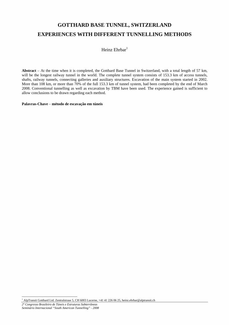
To shorten construction time, the length of the tunnel has been divided into five sections, and is being excavated from several sites simultaneously. Excavation is taking place from the portals at Erstfeld in the north and Bodio in the south, as well as from three intermediate attack points through access tunnels at Amsteg and Faido, and two vertical shafts at Sedrun (Fig. 1).
Figure 1: Gotthard Base Tunnel: Overview
The Gotthard Base Tunnel consists of two parallel single-track tubes with an excavation diameter varying from 8.8 to 9.5 m and linked by cross-passages approximately every 312 m. Two multifunction stations (MFS) are located in the Sedrun and Faido sections, one-third and two-thirds along the length of the tunnel respectively. These will be used for the diversion of trains to the other tube via crossovers, to house technical infrastructure and equipment, and as emergency stopping stations for the evacuation of passengers.
Much of the tunnel will have a very high overburden: more than 1,000 m overburden over approximately 30 km of the tunnel, more than 1,500 m over 20 km, and more than 2,000 m over approx. 5 km. The maximum overburden is about 2,400 m.
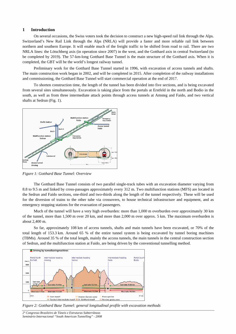
So far, approximately 108 km of access tunnels, shafts and main tunnels have been excavated, or 70% of the total length of 153.3 km. Around 65 % of the entire tunnel system is being excavated by tunnel boring machines (TBMs). Around 35 % of the total length, mainly the access tunnels, the main tunnels in the central construction section of Sedrun, and the multifunction station at Faido, are being driven by the conventional tunnelling method.
Figure 2: Gotthard Base Tunnel: general longitudinal profile with excavation methods
2º Congresso Brasileiro de Túneis e Estruturas Subterrâneas Seminário Internacional “South American Tunnelling” - 2008
2 Selection of the excavation method
2.1 Principles of conventional tunnelling
Conventional tunnelling means the construction of underground openings of any shape with a cyclical construction process comprising
• Excavation, using drilling and blasting or mechanical excavators other than full-face TBMs • Mucking • Placement of the primary support elements such as
Ó Steel ribs or lattice girders Ó Soil or rock bolts Ó Meshes Ó Shotcrete or cast in situ concrete,
either not reinforced or reinforced with wire mesh or fibres. Conventional tunnelling is carried out in a cyclical process of steps, each comprising excavation followed by the
application of relevant primary support, both of which depend on existing ground conditions and ground behaviour. An experienced team of tunnel workers (miners), assisted by standard and/or special plant and equipment, executes each individual cycle of tunnel construction.
The conventional tunnelling method using mainly standard equipment, and allowing access to the tunnel excavation face at almost any time, is very flexible in situations or areas that require a change in the structural analysis or design, and as a result also require changes in the supporting measures.
A standard set of equipment for conventional tunnelling may consist of the following items:
• Drilling jumbo to drill holes for blasting, rock bolting, water and pressure release, grouting etc. • Road header or excavator in cases where blasting is not possible or not economic • Lifting platform allowing the miners to reach each part of the tunnel crown and tunnel face • Lifting equipment for steel sets • Loader or excavator for loading excavated rock onto dump trucks • Dump trucks for hauling excavated rock • Set of shotcrete manipulators for application of wet or dry shotcrete.
Using this standard set of equipment, the following changes can easily be made during construction if rock
conditions change, or if monitoring results call for action: • Increase or decrease of support, e.g. the thickness of shotcrete, number and/or lengths of rock bolts per linear
meter of tunnel, spacing and dimensions of steel arches, number and lengths of spiles, application of shotcrete at the tunnel face, bolting the face etc.
• Variation of ring closure time – which is the time between the excavation of a section of the tunnel and the application of partial or full support – or variation of ring closure distance from the excavation face
• Introduction of primary support ring closure • Variation of the explosive charge per blasting round and variation of detonator sequences.
Other variations during construction allow changes to be made in function of the stand-up time of the rock
encountered: • Increased or decreased length of excavation round (common round lengths vary from 0.5 m to 4.0 m) • Partial excavation by splitting the excavation face into the crown, bench, and invert excavation steps, or even
further in pilot and sidewall galleries and in staggered bench/invert excavations.
If exceptional rock conditions are encountered – regardless of whether or not they were predicted – the conventional tunnelling method can respond with a variety of auxiliary construction technologies such as:
• Grouting: consolidation grouting, fissure grouting, pressure grouting, compensation grouting • Technologies to stabilize and improve the rock ahead of the actual tunnel face
such as forepoling, pipe umbrella, horizontal jet grouting, ground freezing etc.
2º Congresso Brasileiro de Túneis e Estruturas Subterrâneas Seminário Internacional “South American Tunnelling” - 2008
Conventional tunnelling in conjunction with the wide variety of auxiliary construction methods allow experienced project managers to make the most appropriate choice to achieve safe and economic tunnel construction even in situations with changing or unforeseen rock conditions. It allows response in both directions – depending on the rock – changing towards the less or more favourable side. This flexibility makes conventional tunnelling the most advantageous tunnelling method in many projects, which can be located at a shallow depth or under a high overburden, in stable or loading ground, under genuine rock pressure, below the phreatic surface or in dry conditions. Therefore conventional tunnelling is the best method for projects with highly variable rock conditions or variable shapes.
Conventional tunnelling allows • Great variability of the shapes • Good knowledge of the rock conditions by systematic exploratory drillings at tunnel level ahead of the face • Great variability in the choice of excavation methods according to the rock conditions • Great variability in the choice of excavation sequences according to the rock conditions • Optimisation of the primary support using the observational method • Great variability in the choice of auxiliary construction methods according to the rock conditions.
Conventional tunnelling is especially appropriate for • Difficult rock with highly variable rock conditions • Projects with highly variable shapes of cross section • Projects with a higher risk of water inflow under high pressure • Projects with difficult access • Short tunnels.
It is the responsibility of experienced engineers to make the most appropriate choice according to the science of
engineering and their personal experience for a safe and economic tunnel construction. The realisation of the appropriate solution is only possible if the contractual conditions allow it. As shown later on conventional tunnelling calls for adapted contract models.
2.2 Principles of TBM excavation
Tunnelling by TBM is used for the excavation of underground openings of normally circular shape under many types of geological condition, varying from hard rock to very soft sedimentary layers.
Procedures commonly used for tunnelling by TBM are
• Excavation with a rotating cutter wheel in a cyclical or continuous drilling process • Mucking with a mechanical discharging devise • Placement of primary ground support elements such as
Ó Concrete segments Ó Soil or rock bolts Ó Steel ribs Ó Meshes Ó Shotcrete
Two different types of TBMs are used according to the expected ground conditions: open type machines and
closed type machines. Open type machines can be used in ground conditions where the face of the excavation is self-standing.
• Gripper TBM Gripper TBMs are essentially used in rock where the face of the tunnel is self-standing. The advance rate of a Gripper TBM depends essentially on the time required to install rock support devices such as steel ribs, rock anchors, meshes and shotcrete.
• Single Shield TBM Single Shield TBMs are field machines without a closed system for pressure compensation at the tunnel face and can be used where the breast is self-standing. The support will be done with a segment lining. Single Shield TBMs have a very wide range of applications from hard to brittle or soft rock.
2º Congresso Brasileiro de Túneis e Estruturas Subterrâneas Seminário Internacional “South American Tunnelling” - 2008
• Double Shield TBM Double Shield TBMs combine the Gripper principle and the installation of the segments in one coordinated process. Therefore they are technically very sophisticated machines. Double Shield TBMs can be adapted to the particular ground conditions. Double Shield TBMs’s are thus ideally suited for drilling long tunnels in hard rock where geological fault zones occur.
• Earth Pressure Balance Shields With Earth Pressure Balance Shields, the cohesive soil loosened by the cutting wheel serves to support the tunnel face. By creating a support pressure the loss in stability of the tunnel face is prevented. Earth Pressure Balance Shield excavation is carried out in instable ground conditions.
• Slurry shield TBM Slurry shield TBMs cut the ground with a rotary cutter head. The cutter chamber is filled with pressurized slurry mix to stabilize the face of the tunnel. The slurry mix is circulated through pipes to transport it to a slurry treatment plant where the excavated muck is separated from slurry mix.
• Mixshield TBM Mixshield TBMs is used where gravelly geological conditions indicate an unstable tunnel face or mixed geological conditions. At the tunnel face the soil is loosened all over by the cutting wheel rotating in the bentonite suspension. The soil then mixes with the bentonite suspension. The loosened soil mixed with the suspension is pumped through the feeding circuit to the separation plant outside the tunnel.
• Partial face excavation shields Shields with partial face excavation can be used in a wide variety of ground conditions. Mechanical excavators or road headers used for ground excavation. Dependent on the characteristics of the ground, the universal digger can be fitted with an excavation shovel, bucket tooth or hydraulic hammer. These tools can be changed quickly and easily. The excavated soil is removed on conveyor belts or scraper conveyors. Partial face excavation shields are comparatively expensive to install and economical in use.
Tunnelling by TBM usually allows high advance rates, which, in similar ground conditions, are significantly higher than (more than double) the rates attained by conventional tunnelling.
Tunnelling by TBM is generally appropriate for • Projects with constant shapes of cross section • Long tunnels • Projects with good accessibility
Tunnelling by open Gripper TBM (as they are used at the Gotthard Base tunnel) is especially appropriate for
• Comparatively homogenous ground conditions • Projects with a comparatively low risk of water inflow under high pressure
2.3 Criteria for selection of the excavation method
There is no general rule for selection of the excavation method. The selection of the excavation method has to be made based on project-specific criteria depending on the requirements of the project. Project requirements may be
• Health and safety • Environmental aspects • Aspects of future operation • Design (including schedule and costs) • Construction (including schedule and costs) • Third parties and existing facilities including buildings, bridges, tunnels, roads, surface and subsurface
railways, pavements, waterways, flood protection works, surface and subsurface utilities, and all other structures/infrastructure that can be affected by the execution of the works.
On the way from the definition of the project requirements to the realisation of the project, risk factors can
complicate (hazards) or facilitate (opportunities) achievement of the goal.
2º Congresso Brasileiro de Túneis e Estruturas Subterrâneas Seminário Internacional “South American Tunnelling” - 2008
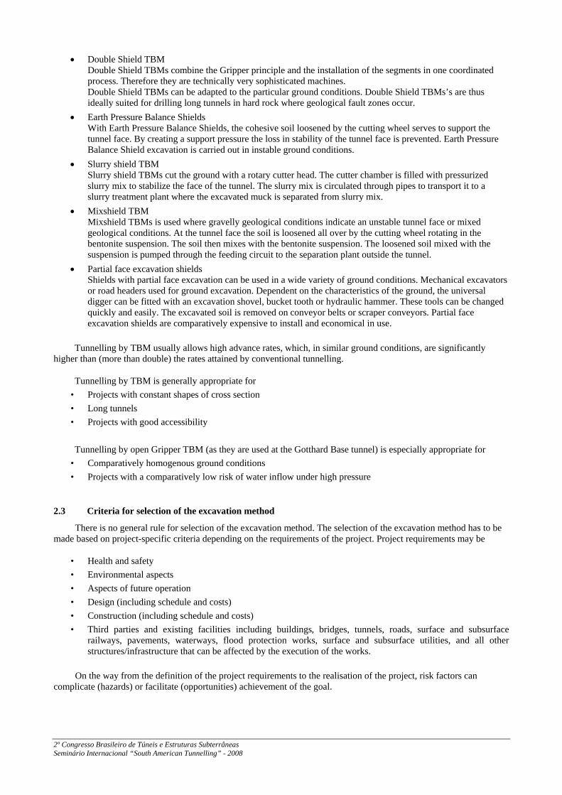
Figure 3: General aspects of risk management
One of the most important measures for mastering the hazards in tunnelling is the selection of the appropriate method of excavation. The selection can only be made based on a careful assessment of the risks and opportunities.
In the case of the Gotthard Base Tunnel, the excavation method had to be determined for the five main construction sections with lengths from 6.5 km up to nearly 15 kilometres.
In the central construction section of Sedrun, the tunnel excavation had to be executed in the northward and in the southward direction starting from the bottom of an 800-metres-deep shaft. The geological conditions were predicted with a high variance from very good hard rock to very poor rock with a high squeezing potential and an overburden of 1.0 km. Additionally, karstic rock zones were expected, and in the southward drive the tunnel had to be excavated close to a concrete arch dam. The northern drive was foreseen with a length of 2.15 km and the southern with 4.6 km.
Under these circumstances, the owner took the decision that only conventional tunnelling should be admitted. Therefore, only the solution of conventional tunnelling came into the tendering process.
For the other four construction sections of Erstfeld (7.1 km), Amsteg (11.4 km), Faido (12.2) and Bodio (14.8), the boundary conditions were not so restrictive. Therefore, mainly the restrictions of construction time and the construction costs determined the selection of the excavation method. These two criteria are mainly influenced by the offer of the contractor. The owner brought a conventional and a TBM solution to the call for tenders for the construction lots of Amsteg and Faido. In the other two cases (Erstfeld and Bodio), the owner saw only a small chance for a competitive conventional solution. Therefore, no official project with conventional tunnelling came into the call for tenders. Nevertheless, the contractors were allowed to offer solutions with conventional tunnelling.
The contractors offered the owner’s solution (TBM drive and conventional tunnelling) for Faido and Amsteg, but no contractor’s solution for conventional tunnelling at Erstfeld and Bodio. Finally, driving by TBM was the most economic solution in all cases.
3 Experiences with conventional tunnelling
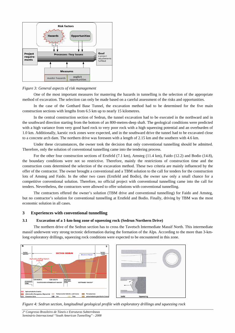
3.1 Excavation of a 1-km-long zone of squeezing rock (Sedrun Northern Drive) The northern drive of the Sedrun section has to cross the Tavetsch Intermediate Massif North. This intermediate
massif underwent very strong tectonic deformation during the formation of the Alps. According to the more than 3-km-long exploratory drillings, squeezing rock conditions were expected to be encountered in this zone.
Figure 4: Sedrun section, longitudinal geological profile with exploratory drillings and squeezing rock
2º Congresso Brasileiro de Túneis e Estruturas Subterrâneas Seminário Internacional “South American Tunnelling” - 2008
The test bores to the north indicated that the 1.1-km-long Tavetsch Intermediate Massif North consists to approximately 70% of soft kakiritic rocks displaying ductile fracture behaviour. Approximately 30% of the rock is hard, and displays brittle facture behaviour. Hard and soft rocks alternate in narrow vertical layers. The predominant hazard is the phenomenon of squeezing rock.
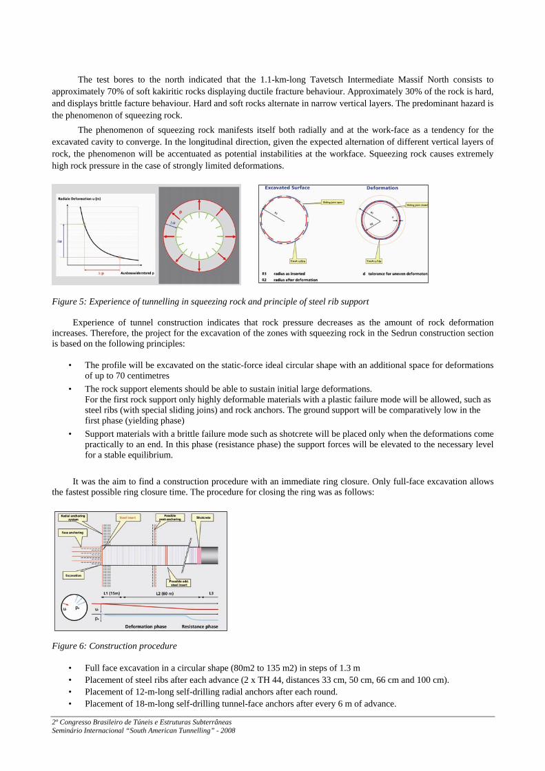
The phenomenon of squeezing rock manifests itself both radially and at the work-face as a tendency for the excavated cavity to converge. In the longitudinal direction, given the expected alternation of different vertical layers of rock, the phenomenon will be accentuated as potential instabilities at the workface. Squeezing rock causes extremely high rock pressure in the case of strongly limited deformations.
Figure 5: Experience of tunnelling in squeezing rock and principle of steel rib support
Experience of tunnel construction indicates that rock pressure decreases as the amount of rock deformation increases. Therefore, the project for the excavation of the zones with squeezing rock in the Sedrun construction section is based on the following principles:
• The profile will be excavated on the static-force ideal circular shape with an additional space for deformations of up to 70 centimetres
• The rock support elements should be able to sustain initial large deformations. For the first rock support only highly deformable materials with a plastic failure mode will be allowed, such as steel ribs (with special sliding joins) and rock anchors. The ground support will be comparatively low in the first phase (yielding phase)
• Support materials with a brittle failure mode such as shotcrete will be placed only when the deformations come practically to an end. In this phase (resistance phase) the support forces will be elevated to the necessary level for a stable equilibrium.
It was the aim to find a construction procedure with an immediate ring closure. Only full-face excavation allows
the fastest possible ring closure time. The procedure for closing the ring was as follows:
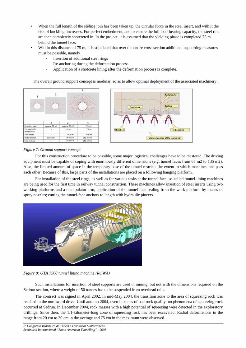
Figure 6: Construction procedure
• Full face excavation in a circular shape (80m2 to 135 m2) in steps of 1.3 m • Placement of steel ribs after each advance (2 x TH 44, distances 33 cm, 50 cm, 66 cm and 100 cm). • Placement of 12-m-long self-drilling radial anchors after each round. • Placement of 18-m-long self-drilling tunnel-face anchors after every 6 m of advance.
2º Congresso Brasileiro de Túneis e Estruturas Subterrâneas Seminário Internacional “South American Tunnelling” - 2008
• When the full length of the sliding join has been taken up, the circular force in the steel insert, and with it the risk of buckling, increases. For perfect embedment, and to ensure the full load-bearing capacity, the steel ribs are then completely shotcreted in. In the project, it is assumed that the yielding phase is completed 75 m behind the tunnel face.
• Within this distance of 75 m, it is stipulated that over the entire cross section additional supporting measures must be possible, namely
J Insertion of additional steel rings J Re-anchoring during the deformation process J Application of a shotcrete lining after the deformation process is complete.
The overall ground support concept is modular, so as to allow optimal deployment of the associated machinery.
Figure 7: Ground support concept
For this construction procedure to be possible, some major logistical challenges have to be mastered. The driving equipment must be capable of coping with enormously different dimensions (e.g. tunnel faces from 65 m2 to 135 m2). Also, the limited amount of space in the temporary base of the tunnel restricts the extent to which machines can pass each other. Because of this, large parts of the installations are placed on a following hanging platform.
For installation of the steel rings, as well as for various tasks at the tunnel face, so-called tunnel-lining machines are being used for the first time in railway tunnel construction. These machines allow insertion of steel inserts using two working platforms and a manipulator arm; application of the tunnel-face sealing from the work platform by means of spray nozzles; cutting the tunnel-face anchors to length with hydraulic pincers.
Figure 8: GTA 7500 tunnel lining machine (ROWA)
Such installations for insertion of steel supports are used in mining, but not with the dimensions required on the Sedrun section, where a weight of 50 tonnes has to be suspended from overhead rails.
The contract was signed in April 2002. In mid-May 2004, the transition zone to the area of squeezing rock was reached in the northward drive. Until autumn 2004, even in zones of bad rock quality, no phenomena of squeezing rock occurred at Sedrun. In December 2004, rock masses with a high potential of squeezing were detected in the exploratory drillings. Since then, the 1.1-kilometer-long zone of squeezing rock has been excavated. Radial deformations in the range from 20 cm to 30 cm in the average and 75 cm in the maximum were observed.
2º Congresso Brasileiro de Túneis e Estruturas Subterrâneas Seminário Internacional “South American Tunnelling” - 2008
Breakthrough took place in October 2007, nine months ahead of the contract schedule. The average advance rate was constantly around 1.3 metres per day. Also, the costs were slightly lower than foreseen. A very successful chapter in the history of conventional tunnelling has been written.
3.2 Tunnel construction close to concrete arch dam with conventional tunnelling (Sedrun Southern Drive)
The limitation on the potential influence on third parties and existing facilities is one key factor for the selection of the excavation method.
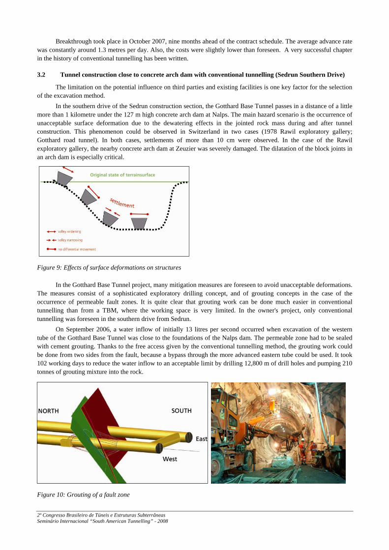
In the southern drive of the Sedrun construction section, the Gotthard Base Tunnel passes in a distance of a little more than 1 kilometre under the 127 m high concrete arch dam at Nalps. The main hazard scenario is the occurrence of unacceptable surface deformation due to the dewatering effects in the jointed rock mass during and after tunnel construction. This phenomenon could be observed in Switzerland in two cases (1978 Rawil exploratory gallery; Gotthard road tunnel). In both cases, settlements of more than 10 cm were observed. In the case of the Rawil exploratory gallery, the nearby concrete arch dam at Zeuzier was severely damaged. The dilatation of the block joints in an arch dam is especially critical.
Figure 9: Effects of surface deformations on structures
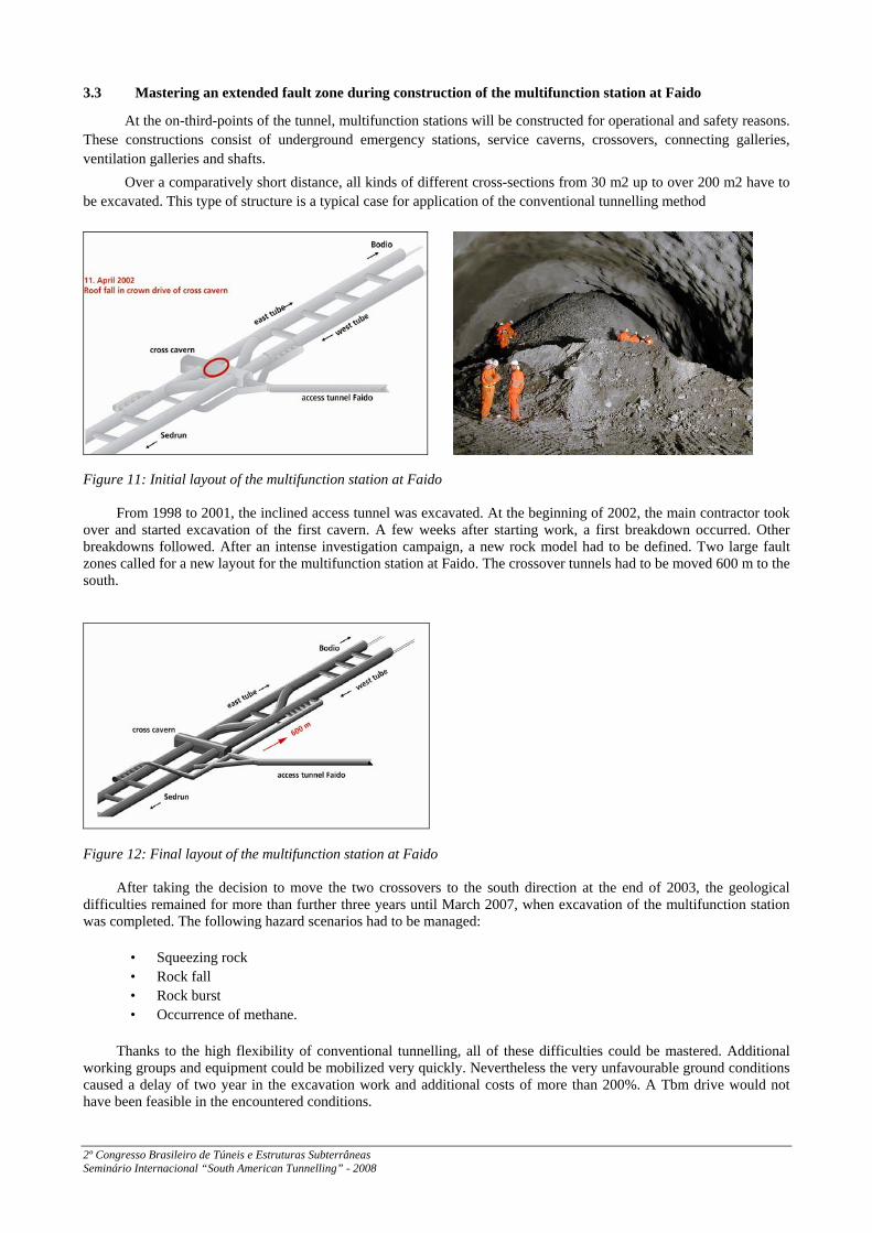
In the Gotthard Base Tunnel project, many mitigation measures are foreseen to avoid unacceptable deformations. The measures consist of a sophisticated exploratory drilling concept, and of grouting concepts in the case of the occurrence of permeable fault zones. It is quite clear that grouting work can be done much easier in conventional tunnelling than from a TBM, where the working space is very limited. In the owner's project, only conventional tunnelling was foreseen in the southern drive from Sedrun.
On September 2006, a water inflow of initially 13 litres per second occurred when excavation of the western tube of the Gotthard Base Tunnel was close to the foundations of the Nalps dam. The permeable zone had to be sealed with cement grouting. Thanks to the free access given by the conventional tunnelling method, the grouting work could be done from two sides from the fault, because a bypass through the more advanced eastern tube could be used. It took 102 working days to reduce the water inflow to an acceptable limit by drilling 12,800 m of drill holes and pumping 210 tonnes of grouting mixture into the rock.
Figure 10: Grouting of a fault zone
2º Congresso Brasileiro de Túneis e Estruturas Subterrâneas Seminário Internacional “South American Tunnelling” - 2008
3.3 Mastering an extended fault zone during construction of the multifunction station at Faido
At the on-third-points of the tunnel, multifunction stations will be constructed for operational and safety reasons. These constructions consist of underground emergency stations, service caverns, crossovers, connecting galleries, ventilation galleries and shafts.
Over a comparatively short distance, all kinds of different cross-sections from 30 m2 up to over 200 m2 have to be excavated. This type of structure is a typical case for application of the conventional tunnelling method
Figure 11: Initial layout of the multifunction station at Faido
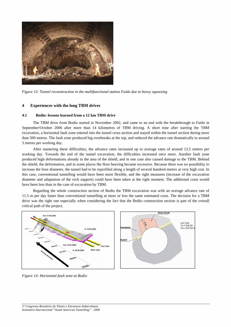
From 1998 to 2001, the inclined access tunnel was excavated. At the beginning of 2002, the main contractor took over and started excavation of the first cavern. A few weeks after starting work, a first breakdown occurred. Other breakdowns followed. After an intense investigation campaign, a new rock model had to be defined. Two large fault zones called for a new layout for the multifunction station at Faido. The crossover tunnels had to be moved 600 m to the south.
Figure 12: Final layout of the multifunction station at Faido
After taking the decision to move the two crossovers to the south direction at the end of 2003, the geological difficulties remained for more than further three years until March 2007, when excavation of the multifunction station was completed. The following hazard scenarios had to be managed:
• Squeezing rock • Rock fall • Rock burst • Occurrence of methane.
Thanks to the high flexibility of conventional tunnelling, all of these difficulties could be mastered. Additional working groups and equipment could be mobilized very quickly. Nevertheless the very unfavourable ground conditions caused a delay of two year in the excavation work and additional costs of more than 200%. A Tbm drive would not have been feasible in the encountered conditions.
2º Congresso Brasileiro de Túneis e Estruturas Subterrâneas Seminário Internacional “South American Tunnelling” - 2008
lìí=NTKMVKOMMP
få=NVKMOKOMMP
b~ëí=íìÄÉ
tÉëí=íìÄÉfå=MVKMSKOMMP
lìí=NSKMTKOMMP
aêáîáåÖ=ÇáêÉÅíáçå
Figure 13: Tunnel reconstruction in the multifunctional station Faido due to heavy squeezing
4 Experiences with the long TBM drives
4.1 Bodio: lessons learned from a 12 km TBM drive
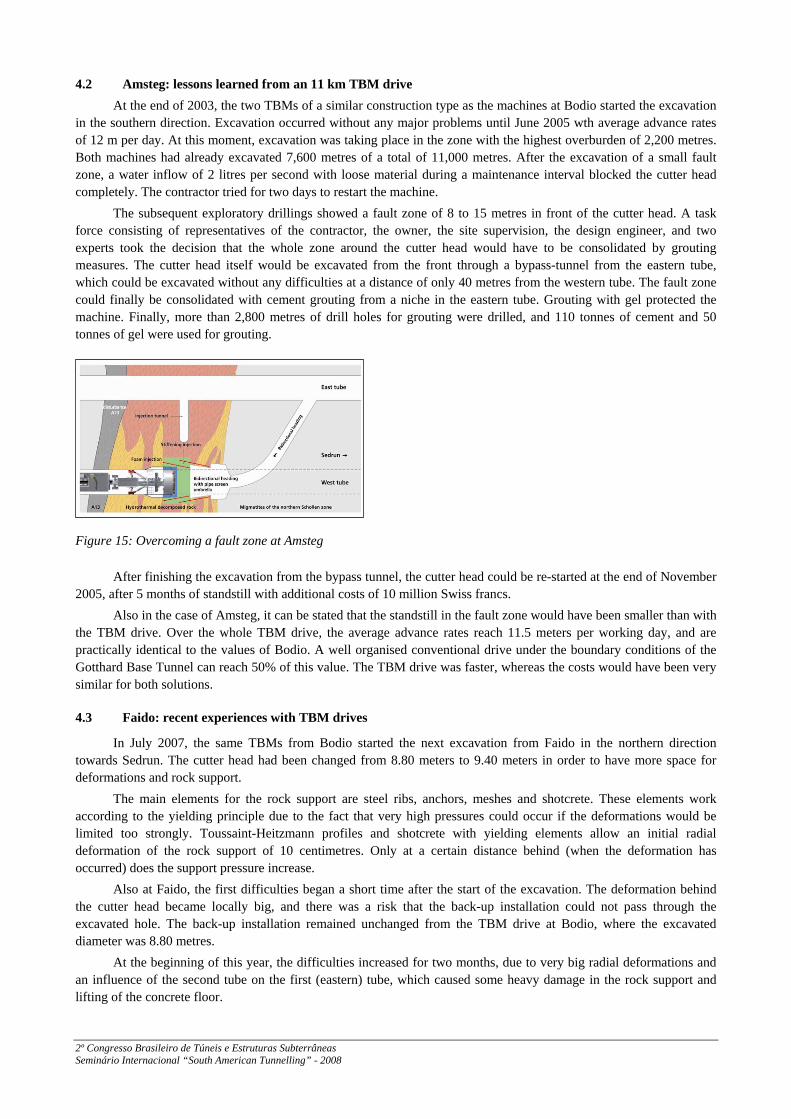
The TBM drive from Bodio started in November 2002, and came to an end with the breakthrough to Faido in September/October 2006 after more than 14 kilometres of TBM driving. A short time after starting the TBM excavation, a horizontal fault zone entered into the tunnel cross section and stayed within the tunnel section during more than 500 metres. The fault zone produced big overbreaks at the top, and reduced the advance rate dramatically to around 3 metres per working day.
After mastering these difficulties, the advance rates increased up to average rates of around 13.5 metres per working day. Towards the end of the tunnel excavation, the difficulties increased once more. Another fault zone produced high deformations already in the area of the shield, and in one case also caused damage to the TBM. Behind the shield, the deformation, and in some places the floor heaving became excessive. Because there was no possibility to increase the bore diameter, the tunnel had to be reprofiled along a length of several hundred metres at very high cost. In this case, conventional tunnelling would have been more flexible, and the right measures (increase of the excavation diameter and adaptation of the rock support) could have been taken at the right moment. The additional costs would have been less than in the case of excavation by TBM.
Regarding the whole construction section of Bodio the TBM excavation was with an average advance rate of 11.5 m per day faster than conventional tunnelling at more or less the same estimated costs. The decision for a TBM drive was the right one especially when considering the fact that the Bodio construction section is part of the overall critical path of the project.
Figure 14: Horizontal fault zone at Bodio
2º Congresso Brasileiro de Túneis e Estruturas Subterrâneas Seminário Internacional “South American Tunnelling” - 2008
4.2 Amsteg: lessons learned from an 11 km TBM drive At the end of 2003, the two TBMs of a similar construction type as the machines at Bodio started the excavation
in the southern direction. Excavation occurred without any major problems until June 2005 wth average advance rates of 12 m per day. At this moment, excavation was taking place in the zone with the highest overburden of 2,200 metres. Both machines had already excavated 7,600 metres of a total of 11,000 metres. After the excavation of a small fault zone, a water inflow of 2 litres per second with loose material during a maintenance interval blocked the cutter head completely. The contractor tried for two days to restart the machine.
The subsequent exploratory drillings showed a fault zone of 8 to 15 metres in front of the cutter head. A task force consisting of representatives of the contractor, the owner, the site supervision, the design engineer, and two experts took the decision that the whole zone around the cutter head would have to be consolidated by grouting measures. The cutter head itself would be excavated from the front through a bypass-tunnel from the eastern tube, which could be excavated without any difficulties at a distance of only 40 metres from the western tube. The fault zone could finally be consolidated with cement grouting from a niche in the eastern tube. Grouting with gel protected the machine. Finally, more than 2,800 metres of drill holes for grouting were drilled, and 110 tonnes of cement and 50 tonnes of gel were used for grouting.
Figure 15: Overcoming a fault zone at Amsteg
After finishing the excavation from the bypass tunnel, the cutter head could be re-started at the end of November 2005, after 5 months of standstill with additional costs of 10 million Swiss francs.
Also in the case of Amsteg, it can be stated that the standstill in the fault zone would have been smaller than with the TBM drive. Over the whole TBM drive, the average advance rates reach 11.5 meters per working day, and are practically identical to the values of Bodio. A well organised conventional drive under the boundary conditions of the Gotthard Base Tunnel can reach 50% of this value. The TBM drive was faster, whereas the costs would have been very similar for both solutions.
4.3 Faido: recent experiences with TBM drives
In July 2007, the same TBMs from Bodio started the next excavation from Faido in the northern direction towards Sedrun. The cutter head had been changed from 8.80 meters to 9.40 meters in order to have more space for deformations and rock support.
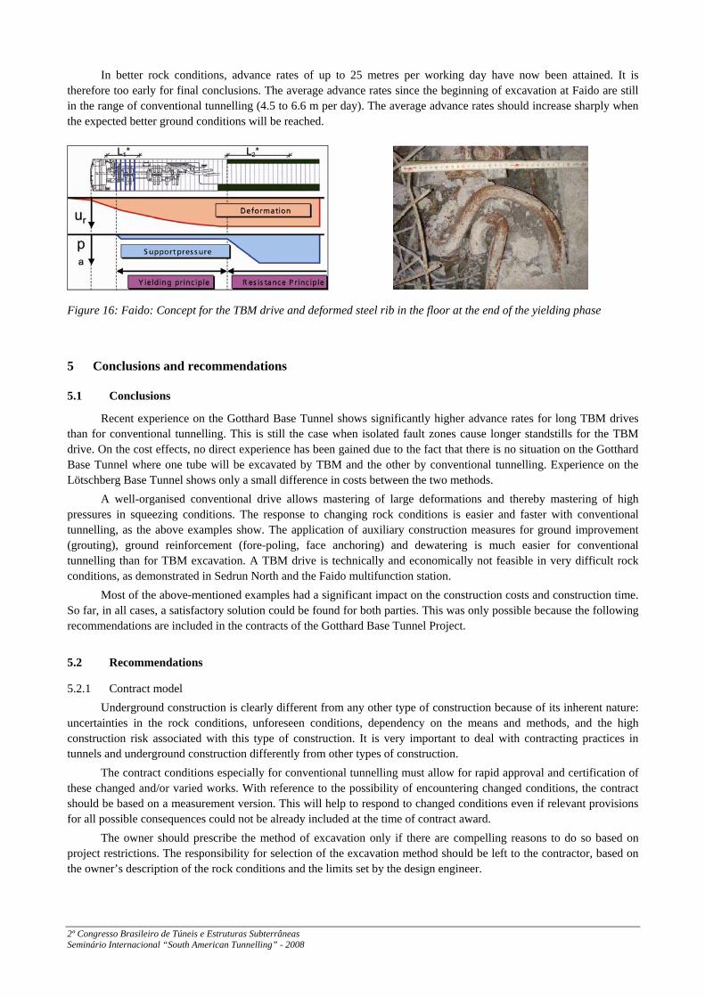
The main elements for the rock support are steel ribs, anchors, meshes and shotcrete. These elements work according to the yielding principle due to the fact that very high pressures could occur if the deformations would be limited too strongly. Toussaint-Heitzmann profiles and shotcrete with yielding elements allow an initial radial deformation of the rock support of 10 centimetres. Only at a certain distance behind (when the deformation has occurred) does the support pressure increase.
Also at Faido, the first difficulties began a short time after the start of the excavation. The deformation behind the cutter head became locally big, and there was a risk that the back-up installation could not pass through the excavated hole. The back-up installation remained unchanged from the TBM drive at Bodio, where the excavated diameter was 8.80 metres.
At the beginning of this year, the difficulties increased for two months, due to very big radial deformations and an influence of the second tube on the first (eastern) tube, which caused some heavy damage in the rock support and lifting of the concrete floor.
2º Congresso Brasileiro de Túneis e Estruturas Subterrâneas Seminário Internacional “South American Tunnelling” - 2008
In better rock conditions, advance rates of up to 25 metres per working day have now been attained. It is therefore too early for final conclusions. The average advance rates since the beginning of excavation at Faido are still in the range of conventional tunnelling (4.5 to 6.6 m per day). The average advance rates should increase sharply when the expected better ground conditions will be reached.
Figure 16: Faido: Concept for the TBM drive and deformed steel rib in the floor at the end of the yielding phase
5 Conclusions and recommendations
5.1 Conclusions
Recent experience on the Gotthard Base Tunnel shows significantly higher advance rates for long TBM drives than for conventional tunnelling. This is still the case when isolated fault zones cause longer standstills for the TBM drive. On the cost effects, no direct experience has been gained due to the fact that there is no situation on the Gotthard Base Tunnel where one tube will be excavated by TBM and the other by conventional tunnelling. Experience on the Lötschberg Base Tunnel shows only a small difference in costs between the two methods.
A well-organised conventional drive allows mastering of large deformations and thereby mastering of high pressures in squeezing conditions. The response to changing rock conditions is easier and faster with conventional tunnelling, as the above examples show. The application of auxiliary construction measures for ground improvement (grouting), ground reinforcement (fore-poling, face anchoring) and dewatering is much easier for conventional tunnelling than for TBM excavation. A TBM drive is technically and economically not feasible in very difficult rock conditions, as demonstrated in Sedrun North and the Faido multifunction station.
Most of the above-mentioned examples had a significant impact on the construction costs and construction time. So far, in all cases, a satisfactory solution could be found for both parties. This was only possible because the following recommendations are included in the contracts of the Gotthard Base Tunnel Project.
5.2 Recommendations
5.2.1 Contract model Underground construction is clearly different from any other type of construction because of its inherent nature:
uncertainties in the rock conditions, unforeseen conditions, dependency on the means and methods, and the high construction risk associated with this type of construction. It is very important to deal with contracting practices in tunnels and underground construction differently from other types of construction.
The contract conditions especially for conventional tunnelling must allow for rapid approval and certification of these changed and/or varied works. With reference to the possibility of encountering changed conditions, the contract should be based on a measurement version. This will help to respond to changed conditions even if relevant provisions for all possible consequences could not be already included at the time of contract award.
The owner should prescribe the method of excavation only if there are compelling reasons to do so based on project restrictions. The responsibility for selection of the excavation method should be left to the contractor, based on the owner’s description of the rock conditions and the limits set by the design engineer.
2º Congresso Brasileiro de Túneis e Estruturas Subterrâneas Seminário Internacional “South American Tunnelling” - 2008
5.2.2 Risk allocation/sharing The allocation of risk between the client and the contractor has a direct relationship to the contractor contingency
as part of the contractor’s bid. It is therefore important to identify a risk-sharing mechanism that is fair and equitable, and that will result in a reasonable contingency by the contractor and a sufficient reserve fund to be provided by the client to address unforeseen conditions. Because the ground belongs to the client, unforeseen conditions due to rock conditions are paid for by the client, if certain tests are met. Means and methods are generally the contractor’s responsibility. The inability to perform under prescribed conditions is a risk to be absorbed by the contractor.
5.2.3 Dispute review board The dispute review board is highly recommended. In this process, a board of independent, experienced, and
impartial members is selected to hear and address disputes. The board consists of three members, one appointed by the client, one appointed by the contractor, and the third who acts as the chairperson of the board, selected by the other two members or appointed by the owner and the contractor together. The board provides recommendations to resolve disputes that participants are unable to solve. According to the recent experiences also at the Gotthard Base Tunnel it is found that this process results in better communication and less acrimony at the job site and more timely and cost-effective resolutions.
5.2.4 Partnering The goal of this process is to minimise disputes and prevent them from escalating in time and value by resolving
them at the lowest possible level in the project organization. It attempts to establish a win-win attitude between the project participants, including the client, the contractor, the engineer, and the construction manager. This process encourages dialogue among the various participants, and relies on reasonable people to resolve disagreements reasonably. It seeks to eliminate adversarial posturing and positioning that often develop when disputes and claims arise. Through this process, a series of dialogues and interactions is developed whereby the team members are encouraged to work out differences in the best interests of the project. When an issue is not resolved at the lowest level, it is brought up to a higher level for resolution. REFERENCES ITA WORKING GROUP 14 (2000), "Recommendations and Guidelines for Tunnel Boring Machines (TBMs)", www.ita-aites.org KOVÁRI, K., AMBERG, F., EHRBAR, H. (2000): “Mastering of Squeezing Rock in the Gotthard Base Tunnel“, World Tunnelling, June 2000, page 234 to 238 EHRBAR, H., SCHÄLLIBAUM I., KÄLIN J., (2001) „Gotthard Base Tunnel, Construction Lot Sedrun, A Challenge for Tunnel Construction“, Proc. ITA World Tunnel Congress, Milan 2001 EHRBAR H., (2004), “Vortriebskonzept in den druckhaften Zonen, Vom Projekt zur Ausführung“, Proc. EUROCK 2004, 53. Geomechanical Colloquium, Salzburg. Rotterdam: Balkema BREMEN, R., (2005), „Oberflächensetzungen als Folge von Tunnelbauten in grosser Tiefe, Stand der heutigen Erkenntnisse“, Proc. AlpTransit Conference, Lucerne 2005. Swiss Tunnelling Society, www.swisstunnel.ch/Shop EHRBAR, H., (2005), „Gotthard Base Tunnel, Sedrun Section, Mastering Squeezing Rock Zones“, Proc. ITA World Tunnel Congress, Istanbul 2005 THE INTERNATIONAL TUNNELLING INSURANCE GROUP (2006), "A Code of Practice for Risk Management of Tunnel works", www.imia.com WILDBOLZ, A., (2006), „Amsteg – TBM Stillstand in der Weströhre, Kleiner Unterschied – grosse Wirkung“, Proc. Swiss Tunnel Congress, Lucerne 2006. Swiss Tunnelling Society, www.swisstunnel.ch/Shop (in german) THEILER, A., MEIER, R., (2007), „Injektion einer wasserführenden Störzone – Konzept und Ausführung“, Proc. Swiss Tunnel Congress, Lucerne 2007, Swiss Tunnelling Society, www.swisstunnel.ch/Shop (in german) ITA WORKING GROUP 19 (2008), "Conventional Tunnelling, Report of the Working Group 19 ", www.ita-aites.org