goal of the lecture - kit · 2 modelling of oleds: motivation • try to understand oled behaviour...
TRANSCRIPT

1
Goal of the lecture
• Microscopic understanding of OLEDs- Modelling of electrical behaviour of OLEDs- Computer simulations
• Devices: Single carrier (monopolar), OLEDs- Space charge limited current- Injection limited current- Electric field distribution, charge carrier densities- Charge carrier confinement
• Transient behaviour• Outlook: Laser diodes

2
Modelling of OLEDs: Motivation
• Try to understand OLED behaviour- Some parameters cannot be measured
• Understand measurments• Extraction of parameters from measurements
- Some parameters cannot be measured directly• Optimisation and design of devices• Prediction of new effects

3
Modelling of OLEDs: Principle of operation
• For electrical modelling, we need:- Charge carrier injection- Charge carrier transport- Formation and decay of excitons
Cathode
Organic film(s)
Anode
Air
Substrate
Exciton formation
Spontan. emission
Injection, transport
Ex=0
x=d
x

4
• Continuity equations for the particle densities (1D)
• Change of density in a small volume dV due to flux (left picture) or creation/decay of particles (right)
• Drift-diffusion approximation for particle fluxes
Modelling of OLEDs: Basic equations
dV
5
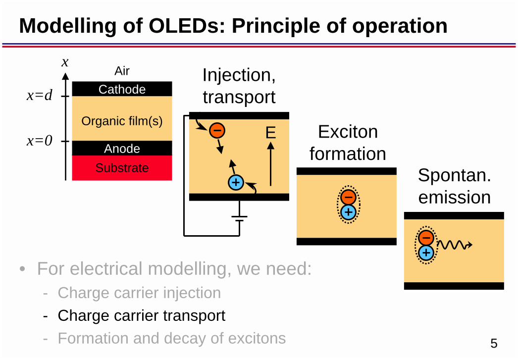
Modelling of OLEDs: Principle of operation
• For electrical modelling, we need:- Charge carrier injection- Charge carrier transport- Formation and decay of excitons
Cathode
Organic film(s)
Anode
Air
Substrate
Exciton formation
Spontan. emission
Injection, transport
Ex=0
x=d
x
6
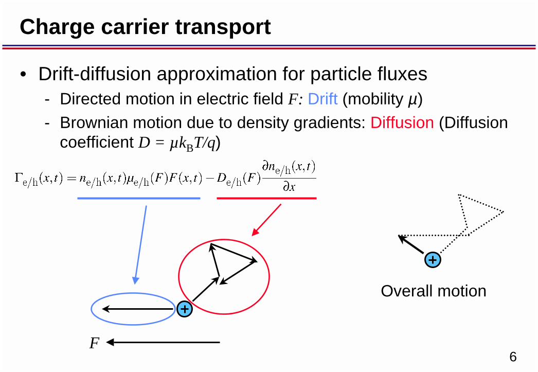
• Drift-diffusion approximation for particle fluxes- Directed motion in electric field F: Drift (mobility µ)- Brownian motion due to density gradients: Diffusion (Diffusion
coefficient D = µkBT/q)
Charge carrier transport
F
Overall motion

7
Charge carrier mobility
• Poole-Frenkel type mobility
- Very often found in organic semiconductors- µ0 and F0 taken from measurements
From I-V-characteristics: Campbell et al., Applied Physics Letters, Vol. 75, p.841,1999
From TOF-measurements: Campbell et al., Applied Physics Letters, Vol. 74, p.2809,1999

8
Modelling of OLEDs: Principle of operation
• For electrical modelling, we need:- Charge carrier injection- Charge carrier transport- Formation and decay of excitons
Cathode
Organic film(s)
Anode
Air
Substrate
Exciton formation
Spontan. emission
Injection, transport
Ex=0
x
x=d

9
Injection
• Injection influences efficiency and turn-on voltage• Influenced by choice of electrode and organic material• Influenced by interface properties (dipoles etc.)• Still not fully understood• Still not fully solved in real devices• Injection gives the boundary conditions for the
continuity equations of the charge carriers- Particle flux at electrodes

10
Injection: Fowler-Nordheim tunneling
• Fowler-Nordheim: Field-induced tunneling of charge carriers across a triangular potential barrier
Experimental verification: Plot ln(J/(d/V)2) vs. d/V for single-carrier devices
E
Electrode organic sem.

11
Injection: Fowler-Nordheim tunneling
• Campbell et al., Journal of Applied Physics, Vol. 82, p.6362, 1997: Fit of Fowler-Nordheim tunneling to I-V-characteristics– Currents can only be fitted
over one order of magnitude for higher temperatures
– Deduced barrier heights vary with temperature and are completely wrong
⇒Fowler-Nordheim tun-neling does not work

12
Injection: Thermionic emission, Schottky effect
• Carriers with enough energy can cross the energy barrier: Thermionic emission
• Energy barrier lowered due to potential of image force: Schottky effect
T
E A*: Richardson constant
Image force potential:

13
Injection: Thermionic emission, Schottky effect
• Barrier lowering is of the same order as the barrier itself• Experimental verification: Plot ln(J/T2) vs. V1/2/T• Proportionality factor is
106-1010 times smaller Richardson constant!
⇒Richardson-Schottky does not work
Campbell et al., Journal of Applied Physics, Vol. 86 , p.5004, 1999

14
Injection: Carrier backflow
• Experimental verification: Vary the mobility while leaving the barrier the same (Shen et al., Physical Review Letters, Vol.86, p. 3867, 2001)
⇒Thermionic injection with backflow works quite well
T
E
Scott et al. Chem. Phys. Lett. 299, 115–119 (1999)
• Mobility in organic semiconductors rather low:- Injected carriers may flow back to the contact and recombine
with their image charges: Injection current is decreased

15
Modelling of OLEDs: Principle of operation
• For electrical modelling, we need:- Charge carrier injection- Charge carrier transport- Formation and decay of excitons
Cathode
Organic film(s)
Anode
Air
Substrate
Exciton formation
Spontan. emission
Injection, transport
Ex=0
x=d
x
16
Exciton formation
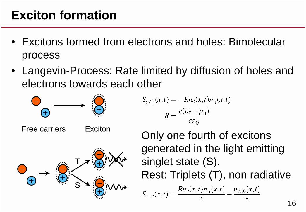
• Excitons formed from electrons and holes: Bimolecular process
• Langevin-Process: Rate limited by diffusion of holes and electrons towards each other
T
S
ExcitonFree carriersOnly one fourth of excitons generated in the light emitting singlet state (S). Rest: Triplets (T), non radiative

17
Exciton transport
• Excitons only subject to diffusion (no charge)• Diffusion coefficient from measurements• Complete dissociation at electrodes: nexc = 0
Ele
ctro
de

18
Determination of electric field
• Often: Solving Poisson‘s equation- May cause numerical problems
• Instead: Time evolution equation for local electric field• Starting with Maxwell‘s equation and applying the
divergence operator
we see that
is spatially constant (current conservation). It is the total current through the device

19
Determination of electric field
• Integration of the equation over the device (in 1D)
leads to an expression for the total current through the device (V: applied voltage):
• If a linear dielectric is assumed, we finally arrive at
for the time derivative of the field
20
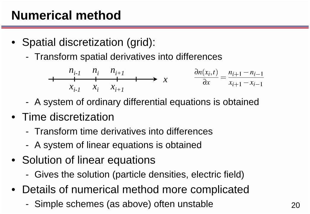
• Spatial discretization (grid):- Transform spatial derivatives into differences
- A system of ordinary differential equations is obtained• Time discretization
- Transform time derivatives into differences- A system of linear equations is obtained
• Solution of linear equations- Gives the solution (particle densities, electric field)
• Details of numerical method more complicated- Simple schemes (as above) often unstable
Numerical method
xxi-1 xi xi+1
ni-1 ni ni+1

21
Current: Space charge and injection limitation
• Simulated I-V-characteristics for a d = 100 nm TPD hole-only device for different injection barriers

22
Current: Space charge and injection limitation
• Ohmic contacts, monopolar device, Poole-Frenkel mobility: Murgatroyd‘s formula (extension of Child‘s law)

23
Current: Space charge and injection limitation
• Particle densities
24
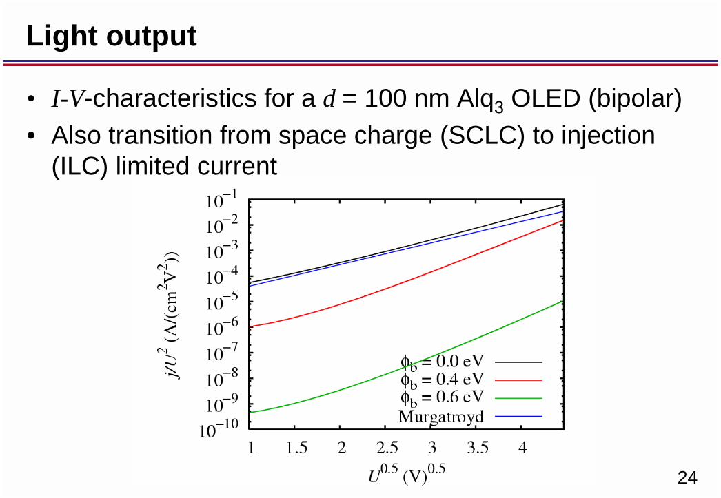
Light output
• I-V-characteristics for a d = 100 nm Alq3 OLED (bipolar)• Also transition from space charge (SCLC) to injection
(ILC) limited current

25
Light output and efficiency
• L-V-characteristics and power efficiency• Decrease of efficiency with φb due to decreased
quantum efficiency (SCLC-ILC)
26
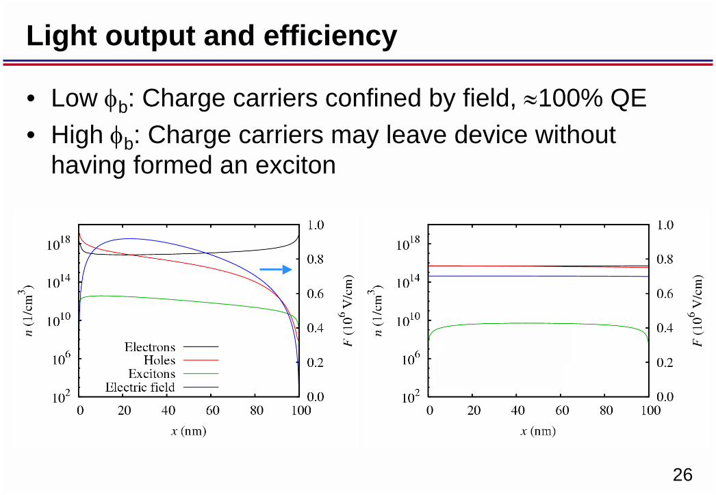
Light output and efficiency
• Low φb: Charge carriers confined by field, ≈100% QE• High φb: Charge carriers may leave device without
having formed an exciton

27
Light output and efficiency
• Unequal hole and electron mobility- Exciton formation near electrode- Exciton dissociation and radiation quenching
• Field dependent exction formation rate
28
Improvement of light output
• Problem: Ohmic contacts not easy to achieve- Materials often unstable, chemically reactive etc.- Injection limited current
• Solution- Confine carriers without electric field- Blocking layers- Most simple: Bilayer device with one transport layer- More advanced: Multilayer to keep emission away from
electrodes

29
Improvement of light output
• Simulation of TPD-Alq3 bilayer OLED• dTPD = dAlq3= 50 nm; U = 10.5 V• Quantum efficency ≈ 95%

30
Transient behaviour
• Application of a current pulse, Alq3 OLED, d = 100 nm• Delay of conduction current and light emission• Voltage rises while OLED is not conducting

31
Transient behaviour

32
Transient behaviour
• Electrons and holes move towards each other from injecting electrodes
• Emission becomes significant when there is enough overlap between electron and hole density
tt t