gnss over-the-air testing using wave field synthesis · gnss over-the-air testing using wave field...
TRANSCRIPT
GNSS Over-the-Air Testing using Wave FieldSynthesis
Alexander Rugamer1, Giovanni Del Galdo2, Johannes Mahr3, Gunter Rohmer1, Gregor Siegert2, Markus Landmann21Fraunhofer Institute for Integrated Circuits IIS, Nuremberg, Germany2Fraunhofer Institute for Integrated Circuits IIS, Ilmenau, Germany
3Technical University Ilmenau, Germany
BIOGRAPHY
Alexander Rugamer received his Dipl.-Ing. (FH) degreein Electrical Engineering from the University of AppliedSciences Wurzburg-Schweinfurt, Germany in 2007. Sincethe same year he works at the Fraunhofer Institute for In-tegrated Circuits IIS in the field of GNSS receiver devel-opment. He was promoted to Senior Engineer in February2012. Since April 2013 he is head of a research group deal-ing with secure GNSS receivers and receivers for specialapplications. His main research interests focus on GNSSmulti-band reception, integrated circuits and immunity tointerference.
Giovanni Del Galdo received his Masters degree in 2005in telecommunications engineering from the Politecnico diMilano and in 2007 his PhD from the Ilmenau Universityof Technology (TUI). He joined the Fraunhofer IIS and theInternational Audio Laboratories Erlangen as senior scien-tist. In 2012 he was appointed full professor at TUI as thehead of the DVT Research Group, a joint activity betweenTUI and Fraunhofer IIS. His current research interests in-clude the analysis, modeling, and manipulation of multi-dimensional signals, over-the-air testing for terrestrial andsatellite communication systems, and sparsity reconstruc-tion methods.
Johannes Mahr received his Master degree in Electrical En-gineering from the University of Technology Ilmenau, Ger-many in 2012. Since that year he worked at the Universitydepartment ”Digital Broadcasting Research Laboratory”.His main research interest was image based motion detec-tion of vehicles. He was also working on the simulationof wave field synthesis at the Facility for Over the Air Re-search and Testing (FORTE) in Ilmenau.
Gunter Rohmer received his Dipl.-Ing. degree in ElectricalEngineering in 1988 and the PhD in 1995 from the Uni-versity of Erlangen, Germany. Since 2001 he is head of adepartment at the Fraunhofer IIS dealing with the develop-ment of components for satellite navigation receivers, in-door navigation and microwave localization systems.
Gregor Siegert received his Dipl.-Ing. degree in MediaTechnology from the University of Technology Ilmenau,Germany in 2010. Since that year he works at the Fraun-hofer IIS within the Project Group ”Wireless DistributionSystems / Digital Broadcasting”. He is mainly occupiedwith the Facility for Over the Air Research and Testing(FORTE). The Facility covers the test and development ofsatellite and terrestrial based communications systems un-der realistic but repeatable propagation conditions.
Markus Landmann received the Dipl.-Ing. and Dr.-Ing.(Ph.D.E.E.) degrees in Electrical Engineering from Ilme-nau University of Technology (TUI), Germany, in 2001 and2008 respectively. From 2001 to 2003 he worked as a re-search assistant and instructor at TUI. In 2004 he was de-veloping advanced antenna array calibration methods andhigh resolution parameter estimation algorithm (RIMAX)for propagation studies at MEDAV Company. In 2005 hewas visiting researcher and instructor at Tokyo Instituteof Technology (Takada Laboratory) in the field of chan-nel measurement and estimation techniques. From 2006to 2008 he was finalizing his PhD thesis whilst a researchassistant and instructor TUI. Between 2008 and 2009 hisprojects were in wireless propagation, channel modelling,and array signal processing for TUI and Tokyo Institute ofTechnology. In 2010 he started working for Fraunhofer IIS.He is mainly responsible for the Facility for Over the AirResearch and Testing (FORTE).
ABSTRACT
This paper presents an over-the-air (OTA) wave field syn-thesis (WFS) system for test and certification of GNSS re-ceivers. We discuss its application with respect to jam-mers, spoofers and classified signals and compare it to thestate-of-the-art in GNSS receiver testing. Having outlinedthe OTA WFS system architecture, different test cases aredescribed. We verify the emulated OTA environment onone selected test case in an experiment emulating a realis-tic GNSS signal and artificial jammers, while employing a2x2 GNSS array antenna with a 4 channel receiver as de-
1931

vice under test. The results in terms of direction of arrivalestimation and jammer mitigation are finally presented toproof the concept and feasibility of the multi-directionalover-the-air testbed. Moreover these results show the needfor accurate jammer propagation modelling.
INTRODUCTION
Multiple-Input Multiple-Output (MIMO) Over-The-Air (OTA)testbeds are typically deployed for certification, performancetesting and product evaluation of mobile devices utilizingbroadband wireless technologies, e.g. Long Term Evolu-tion (LTE) or LTE-Advanced. However, the demand for areliable performance assessment of next generation GlobalNavigation Satellite System (GNSS) receivers is constantlyincreasing. In contrast to a mobile phone that encounters aharsh mobile environment only, GNSS receivers are alsofaced with intentional interferences. This is becoming acritical issue, as more and more GNSS receivers are usedfor security related applications. These are the traditionalmilitary GNSS services, flight approach and Ground BasedAugmentation Systems (GBASs). But besides that, up-coming consumer applications may incorporate AdvancedDriving Assistance Solutions (ADAS) up to automatic driv-ing or guidance of blind people. Moreover, GNSS time iswidely used for synchronisation of distributed systems, e.g.of mobile phone base station networks, phase-synchronouscurrent injection of decentralized power plants and manymore.
Due to the inherently low power of GNSS signals (approx.-127 dBm received signal power on earth), the GNSS bandsare dominated by white Gaussian noise. The noise is abouta hundred to a few thousand times stronger than the GNSSsignals themselves. As a consequence, the GNSS signalsare extremely susceptible to all types of interferences. Theseinterferences can be unintentional, e.g. the harmonics ofcertain oscillators that translate into single Continuous Wave(CW)-tones or multi-tones in the GNSS spectrum. How-ever, there are also more and more intentional interferersreadily available on the Commercial-Off-The-Shelf (COTS)market, mostly sold over the internet, even if their use isillegal in most countries. Whereas jammers are used fordenial-of-service attacks, spoofers pose an even bigger threat,since they can intentionally lead a receiver to estimate afake position and/or time without recognizing it. All ofthese interferences, unintentional or on purpose, have oneaspect in common. Only a very small amount of outputpower is sufficient to exceed the thermal noise floor andtherefore to effectively disturb the GNSS signals on the re-ceiver side.
To provide protection against interferences, GNSS receiverusing phased array antennas can be a powerful solution.
For instance, a very effective interference mitigation methodis utilizing a Controlled Reception Pattern Antenna (CRPA).
This type of phased array antenna places nulls in the direc-tion of the interferer to protect the receiver from impair-ment. Already commercial products are available on themarket, like the 7-element CRPA named GAJT from No-vatel/Qinetiq [1].
A more sophisticated solution provides a beamsteering an-tenna, e.g. developed by the German Aerospace Center(DLR) and used within the BaSE project [2]. In this ap-proach, a beam is steered in each direction of the satellitesto be received. Due to the increased gain in a specific direc-tion, possible interferences coming from other directionsare already attenuated. Moreover these beamsteering an-tennas give the possibility to detect spoofing. Typically, aspoofer broadcasts all signals from a single point in space,whereas the desired GNSS information is inherently linkedto a spatial diversity of the satellites. By using a phasedarray antenna, the Direction of Arrival (DoA) can be esti-mated at the receiver side, independently from the transmit-ted GNSS message. This cross check enables an effectivespoofing detection [3].
Another non-antenna dependent defence against spoofersis to use encrypted signals. While the encrypted GPS PPSis intended for military use only, the Galileo system offerswith its Public Regulated Service (PRS) an encrypted sig-nal for civil usage not limited to military operations. Nev-ertheless, it is a classified signal. This could mean that theoperation of non-certified PRS receivers is prohibited in anunprotected environment.
At the moment, mass-market receivers, e.g. shipped withsmartphones, are tested and verified for position accuracy,acquisition sensitivity, time-to-first-fix and other benchmarks,but not for their robustness against intentional interferences.Testing, qualification and certification at least for safety-critical receivers is regarded a must and necessary to guar-antee a certain minimum standard. Hence, the goal of thiswork is to develop a new testing method for interferencerobustness assessment of GNSS receivers using integratedantennas, external ones, but especially also receivers withphased array antennas. The test applications shall rangefrom classical open service GPS/Galileo signals to classi-fied signals (e.g. GPS PPS or Galileo PRS). To avoid inher-ent drawbacks of conventional approaches (e.g. conductedor free field tests), the method of choice is OTA testing un-der repeatable and shielded laboratory conditions. Specialcare will be taken for the emulation of the propagation con-ditions that jammers and spoofers are subject to.
First state of the art test setups for GNSS receiver testingare summarized. Then we introduce our multi-directionalover-the-air testbed for GNSS receiver testing, whereas itstest cases are discussed in following Test cases section. Fi-nally, the proposed concept is proven and demonstratedwith a directional GNSS test receiver setup before we drawconclusion.
1932

STATE OF THE ART TEST SETUPS
Three different test setups can be distinguished and willbe briefly described in the following. Furthermore, theirusability w.r.t. the targeted application of GNSS robustnesstests against interference is analysed.
Conducted tests
Conducted tests are regarded as the state-of-the-art. In thesesetups, a RF-GNSS constellation emulator is directly con-nected to the Device Under Test (DUT) bypassing the an-tenna. Such a RF emulator provides great advantages in thereceiver development and verification phases and finally inperformance evaluations. Moreover completely differentscenarios in terms of satellite constellation used, dynamicsof the movement, multipath environment and so forth caneasily be set up and tested. However there are still severallimitations. Firstly, the DUT as well as jammers or spoofersmay have integrated antennas that make a direct connec-tion impossible. Secondly, cable-connected tests bypassthe antenna characteristics and therefore neglect its influ-ence on the receiver performance. This is a major limi-tation for mass-market receivers with integrated antennas(e.g. smartphones) as well as for sophisticated beamform-ing receivers where the antenna(s) of the device are a criti-cal factor in the performance evaluation.
Free field tests
To avoid the shortcomings of a conducted test, a free fieldtest range is the common choice to evaluate receivers withtheir antenna. However, the test conditions are not reallyreproducible, which makes the direct comparison of differ-ent devices or algorithmic implementations difficult (e.g.the GNSS satellite constellations, weather conditions or mul-tipath environment might vary between each test run). Ad-ditionally, no future or intentionally changed GNSS con-stellations can be simulated. To assess the robustness of areceiver, optimize its algorithms, or to certify its perfor-mance in presence of interferences a specially protectedtest range is necessary. Such protected ranges are avail-able for military tests, e.g. in the missile test range Vidsel,Sweden [4] or at the White Sands Missile Range JAMFESTin New Mexico, USA [5]. Due to their military origin theyare most often only temporally available and not alwaysopen for public or commercial usage. Conventional free-field test ranges like the GATE testbeds in Germany arenot suited to test the receiver’s robustness against interfer-ence. The operation of a powerful jammer or spoofer inan open field would also affect surrounding receivers andtherefore requires a special frequency license to be legallyauthorized. Moreover, the testing, optimization, and verifi-cation of not yet certified receiver designs that incorporateclassified signals (e.g. Galileo PRS) are generally not al-lowed in conventional free field test beds, since stringentanti-tamper requirements and limitation of radiation haveto be guaranteed. This issue was also identified in a study
from 2009, which discussed the requirements and conse-quences if GATE was extended for Galileo PRS usage [6].
Uni-directional over-the-air tests
The OTA testing approach combines the advantages of bothprevious methods and overcomes their inherent drawbacks.In general the DUT is placed inside an anechoic chamber inwhich the real-world scenario, e.g. a GNSS receiver is sub-ject to interference, is emulated via an OTA illuminationantenna. A GNSS constellation simulator is used to gener-ate arbitrary test signals and the receiver is tested togetherwith its antenna(s). This approach provides a repeatableand fully controllable test environment, with no need forspecial frequency licensing or other anti-tamper restraintsthanks to the anechoic chamber.
Currently, in the GNSS domain, these OTA setups are usedmainly for Assisted GPS (A-GPS) testing of mobile phones,that employ integrated antennas for multiple services (e.g.LTE, WiFi, GPS, etc.). Different commercial GNSS OTAtest systems are available on the market, e.g. from Spirent1
or Agilent2. These systems only use a single transmissionantenna to radiate the composite RF signal of all GNSSsatellites and also the interferers to be simulated. However,this approach neglects the capabilities of beamforming an-tennas, that have a clear benefit in a real-world environmentwith multi-directional sources.
The consequent enhancement of these single transmitteruni-directional OTA testbeds is to use a dedicated trans-mit antenna for each satellite to be emulated in a certainconstellation. This approach allows now testing of GNSSreceivers that employ beamforming as it requires spatial ar-ray processing. First commercial solutions are available onthe market, e.g. the GSS77903 from Spirent, intended forCRPA testing. In this setup the RF constellation simula-tor provides separated RF outputs for the satellites to besimulated. However, also this approach faces some limita-tions. Firstly, the physical setup of the transmit antennashas to be replicated in the anechoic chamber in such a way,that the intended scenario matches the actually emulatedone. A change in the scenario constellation results in theneed of a physical reordering of the transmit antennas tomatch the emulated satellite position in terms of azimuthand elevation. Secondly, the movement of the satellites isonly simulated in the broadcasted navigation messages, i.e.the physical transmit antennas do not change their positionover time. This may lead to problems in long term tests.Thirdly, the emulation of interference signals that are sub-ject to multipath propagation is also limited to the physical
1http://www.spirent.com/˜/media/Datasheets/Mobile/8100\_AGPS\_OTA\_Test\_Solutions\_datasheet.pdf
2http://cp.literature.agilent.com/litweb/pdf/5990-4655EN.pdf
3http://www.spirent.com/˜/media/Datasheets/Positioning/GSS7790.pdf
1933

alignment of the transmit antennas and cannot be changedwithin the tests in an arbitrary way.
In general, a similar problem is present in the field of MIMOdevice testing in the communication area, e.g. for LTEmobile phones and systems. One approach used there toinclude the spatial interaction between antennas and ra-dio environment is the application of Wave Field Synthesis(WFS) for testing wireless equipment. This is also knownas Over-The-Air testing and is the technology of choice fortesting the full potential of MIMO systems.
An OTA system with WFS can be regarded as an evolu-tion of the previously described uni-directional OTA se-tups. Here, the physical direction of the received GNSSsignals, multipath components or jammers are emulatedwith WFS. This approach also allows for a continuous an-gular motion of the transmitter (satellite, jammer, spoofer)in space. Moreover, huge dynamic changes, in terms ofdoppler shift, can be emulated (e.g. acceleration of a rocketor plane) via WFS without the need of physically movingthe DUT.
To the authors’ knowledge, the use of an OTA system em-ploying WFS for GNSS testing has not been used nor de-scribed yet. In the following the paper discusses the ar-chitecture of an OTA system incorporating WFS for GNSStesting.
SYSTEM ARCHITECTURE OF THEMULTI-DIRECTIONAL OVER THE AIR TESTBED
Fraunhofer IIS operates a laboratory, called Facility for Over-the-air Research and Testing (FORTE) in Ilmenau, Ger-many. This facility hosts two research platforms in satelliteand terrestrial communication, referred to as SatCom andMIMO-OTA testbeds. The MIMO-OTA research is mainlyfocussed at OTA test methodologies, Wave Field Synthesis,Cognitive Radio (CR) nodes and also evaluation of GNSSreceivers. The benefits from this controlled test environ-ment are clearly the accurate and reproducible performanceassessments of wireless terminals equipped with multipleantennas. With the projected equipment, a state-of-the-artOTA installation is and will become available in near future(fully operational at the end of 2014/beginning of 2015).
Specifications of the complete OTA test laboratory
The connectivity of the OTA channel emulators producedby IZT GmbH will be 12 × 32 (12 input, 32 phase coher-ent physical output channels), currently 8×28 channels aresupported. Every single physical channel (out of 12 × 32)is hereby convoluted with its unique channel impulse re-sponse controlling delay, phase and amplitude of the in-dividual signals. Each of the 32 output signals is the su-perposition of the 12 convoluted input signals. The signalbandwidth supported is 80 MHz across a frequency rangefrom 350 MHz to 3 GHz (for 4×4 channels up to 18 GHz).
For CR and GNSS testing two frequency bands with largerseparation can be used for emulation, but still with an in-stantaneous bandwidth of 80 MHz for each band. The max-imum RF output power is +10 dBm. The generation of thedelay characteristics can be accomplished by performingthe convolution of the signal with the channel impulse re-sponse either in time or frequency domain.
In Figure 1 the general OTA test setup is depicted. Note,that in case of GNSS receiver evaluation the uplink path isnot required and all available channels (12×32) are used togenerate the GNSS downlink channel applying WFS. ForWFS, each of the 28 (in future 32) available dual-polarizedOTA illumination antennas radiate a signal with well-definedphase and a plane wave for a certain direction at the DUT,see Figure 3 for a visualization of this principle.
The convolution of the 12 input signals with the 12 × 32complex impulse responses has to be performed in realtime. By employing such a WFS the constituted wave fieldcan be arbitrarily shaped to emulate real-world electro mag-netic environments.
Adaptation of the OTA testbed for GNSS receiverrobustness evaluation
In this paper the current communication-based installationis analysed and its suitability for GNSS testing is assessed,especially for scenarios involving interferences. The adaptedOTA setup is depicted in Figure 2.
A tailored solution of a Spirent GNSS satellite constella-tion simulator generates an individual digital baseband out-put signal for each satellite to be emulated. Two carrierfrequencies with up to 8 satellite channels are supported,expandable to max. 40 satellite channels. All GNSS aresupported, namely GPS, Galileo, GLONASS and Beidou.Moreover, also the support of the encrypted Galileo PRSon E1 and E6 is foreseen. The maximal digital 3-dB band-width of each channel is 61 MHz which is even sufficientfor the complete Galileo AltBOC signal.
The delay between the satellites and the DUT will be ap-plied to the individual baseband signals of each satellitein the GNSS satellite emulator. A maximum of 12 base-band signals (e.g. 6 Galileo E1/E6) are streamed via opti-cal 10 GBit/s links to the channel emulator consisting of aso called FDSP units, see Figure 2. This channel emula-tor adjusts the correct signal power of the simulated con-stellation according to the chosen propagation conditions.Another input to the OTA WFS are the spatial mapping pa-rameters of each simulated satellite provided by a GNSSsatellite emulator (in this case from Spirents PosApp). TheRF output signals are finally radiated via the OTA illumina-tion antennas that are surrounded by the shielded anechoicchamber.
In that way the realistic angular characteristic of the wavefield for the DUT (e.g. a GNSS receiver with integrated
1934

LTE-Basestation-Emulator
4x4 MIMO
Downlink Uplink
8-Antennas - inverse WFS for Uplink (8x4)
28-Antenna – WFS
e.g. LTE 4x4 MIMO-scenario with channel emulation
in down- AND uplink
Control - PC
LTE- MIMO device(4 Antennas)
Channel emulator(12x32)
12RF in(e.g. 8 used for uplink MIMO inverse WFS)
32RF out(e.g. 28 used for
downlink MIMO WFS)
Figure 1: MIMO-OTA closed loop test setup.
Digital to analog
upconverter
Wave form synthesizer
with channel emulator
GNSS constellation
simulator
10 GBit switchFibre
Distribution
.
.
.6*10 GBit LAN fibre
1*10 GBit LANfibre
6*10 GBit LANfibre FDSP #4 DAU #4
1*10 GBit LANfibre
6*10 GBit LANfibre FDSP #3 DAU #3
1*10 GBit LANfibre
6*10 GBit LANfibre FDSP #2 DAU #2
1*10 GBit LANfibre
6*10 GBit LANfibre
1*10 GBit LANfibreFDSP #1 DAU #1
1*10 GBit LANfibre
6*10 GBit LANfibre FDSP #16 DAU #16
1*10 GBit LANfibre
6*10 GBit LANfibre FDSP #15 DAU #15
RF out #1
RF out #2
RF out #3
RF out #4
RF out #5
RF out #6
RF out #7
RF out #8
RF out #29
RF out #31
RF out #30
RF out #32
12 digital base-band channels
Interference generator(e.g. AWG)
10 GBit LAN fibre
.
.
.
Elevation/Azimuth/SNR for the 12 digital baseband signals
.
.
.
Figure 2: Detailed diagram of the OTA setup for GNSS receiver tests. A GNSS satellite simulator provides up to 12 streamsin digital baseband. All of these inputs are distributed via fibre optic LAN to each of the 16 FPGA-Digital Signal Processors(FDSPs), where the actual signal convolution with the channel impulse response is performed. Each FDSP streams two com-posite digital output signals over LAN to its corresponding Digital to Analogue Upconvertor (DAU), which transmits the outputsignals via the OTA illumination antennas.
1935

Inside view anechoic chamber Principle
Single illumination antennas Superposition of EM waves
Plain wave
Area of interest
Figure 3: Principle of wave field emulation in OTA test system.
phased array antenna) including jammers and spoofers isemulated. Special care has to be taken for the emulationof the latter, as these interferers are usually subject to ter-restrial channel effects, i.e. multipath propagation. In theworst case, a phased array based receiver might be able tonull the LoS direction of an interferer, but a strong reflec-tion from another Angle of Arrival (AoA) might also causesevere harm to the receiver positioning algorithm. The ane-choic chamber, surrounding the OTA illumination anten-nas, provides an isolation of approx. 80 dB, making thistestbed also suited to be used with classified signals (e.g.Galileo PRS). Moreover, also receivers which are not cer-tified yet in their anti-tamper properties (e.g. within thedevelopment phase) can already be used for tests with theirantenna in this protected environment.
The scientific and technological challenges of the adapta-tion of the OTA testbed to full GNSS needs, are the hard-ware and resource efficient spatial temporal emulation ofthe wave field for the GNSS satellites, as well as for jam-mers and spoofers. In the following different test cases willbe discussed.
GNSS RECEIVER TEST CASES
In standard conducted tests GNSS receiver are most of-ten qualified for parameters like acquisition time in cold/-warm/hot-start mode, acquisition and tracking sensitivity,time-to-first-fix and so forth. Additionally, there are testsdefined against continuous wave and pulse interferences.But these interference tests are rather theoretical since theyare quite abstract to the challenges in the real world. Sinceanti-jamming capability is getting more and more impor-tant an OTA setup provides much more possibilities of in-
terference tests.
In general, the OTA system with its WFS can be used as anarbitrary waveform generator (AWG). This means that arti-ficial jammer signals can be generated e.g. CW, swept-CW,narrow/wideband-noise, pulses, chirps with different pa-rameters and power levels. Moreover, the anechoic cham-ber can be used to record real-world jammers and reusethem afterwards for the different test cases described in thefollowing.
As mentioned before, array antennas are a promising wayof interferer mitigation in GNSS processing. Since the ac-curacy of the WFS is, among other parameters, highly linkedto the size of the array antenna under test, it is necessary toinvestigate the possible DUT diameters. Table 1 gives anoverview of different array antennas available today withtheir diameters.
Test case 1: Jammer & spoofer emulation considering LoSonly
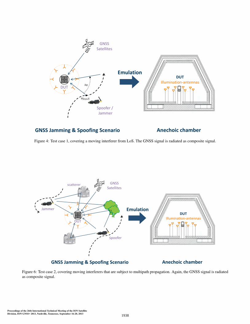
This test case is designed to test GNSS receiver robustnessagainst strong interferers (jammers and/or spoofers). Theinterferer’s velocity and distance relative to the DUT can becontrolled by the emulation environment. In this case, allGNSS signals are transmitted as composite signal via a sin-gle antenna. This means, the receiver’s capability of spatialprocessing of the GNSS signal can not be tested – similarto the A-GPS test method described in Section State-of-theArt. However, the capabilities of the described OTA systemcan be fully used for jammer and/or spoofer emulation. Bysweeping the interference signal in arbitrary horizontal di-rections (only 2D arrangements are taken into account atthe moment) around the receiver up to extremely high dy-
1936

Table 1: Overview of some available CRPA antennas
Manufacturer Model Nr of Elements Diameter [mm] ReferenceAntCom 3-Element-5-Channel CRPA 3 120 [7]AntCom 4-Element CRPA L1/L2 GPS 4 120 [7]AntCom 5-Element-10-Channel 5 150 [7]AntCom 7-Element CRPA 7 178 [7]AntCom 15-Element-30-Channel CRPA 15 267 [7]DLR Galant 4 270 [3]Novatel GAJT 7 290 [1]Satimo CRPA 7 365 [8]
Figure 5: Comparison of mean error [dB] between WFSand optimum plane wave for aperture diameter (sweet spot)versus number of antennas. Note that for this simulation theangular spacing of the OTA antennas is set to the minimumvalue of 7.5 ◦, which gives a varying covered angular rangefor different numbers of antennas.
namics, the receiver’s interference mitigation algorithms,e.g. adaption of the CRPA and interferer DoA estimation,can be challenged. The interferer is only simulated for Lineof Sight (LoS), i.e. channel impairments are not simulated.This test scenario covers the minimum requirement of OTAGNSS robustness tests. Currently, the maximum number ofuncorrelated interferences that can be emulated in parallelis 8 (in 2015 up to 12). The setup for this scenario is illus-trated in Figure 4.
As the emulation accuracy depends on the size of the DUT,a simulation was performed to analyse the emulation errorw.r.t. the DUT diameter and desired angular range. Fig-ure 5 shows that with an increasing diameter of the DUTthe emulation accuracy decreases. However, since GNSSreceivers work at a very low SNR in the range of 0-30 dBeven after correlation, an emulation accuracy larger thanthis range is not required. Due to the physical size of theused antennas, the minimum spacing between the OTA il-
0.1 0.2 0.3 0.4 0.5 0.6 0.7 0.8 0.9−50
−45
−40
−35
−30
−25
−20
−15
−10
−5
Diameter sweet spot [m]
WFS
Err
or[d
B]
32 Antennas28 Antennas16 Antennas
Figure 7: Comparison of mean error [dB] between WFSand optimum plane wave for different aperture diameters(sweet spot) and three different numbers of antennas (16,28, 32). These results always correspond to an angular cov-erage of 360 ◦, i.e. the spacing between adjacent antennasvaries for different numbers of antennas.
lumination antennas is 7.5 ◦. This means that the coveredangular range is always the product of 7.5 ◦ times the num-ber of antennas. From Figure 5 it can be seen that the fullangular range of 210 ◦, which corresponds to 28 antennas,results in a maximum DUT diameter of 65 cm for 30 dBSNR and 80 cm for a SNR of 20 dB. If several jammers orspoofers have to be emulated with a larger separation than210 ◦, this range can be subdivided resulting in an overallsmaller maximum DUT diameter.
In comparison with the overview of the available GNSSarray antennas in Table 1, the possible aperture diameter of0.65 m is sufficient for all of the mentioned antennas in thissimulated 2D arrangement with one interference source.
Test case 2: Jammer & spoofer with multipath propagation
The previous test case is somehow relevant to show the ro-bustness of a GNSS receiver in a first step. However, inreality not only the LoS path between spoofer/jammer and
1937
DUT
GNSSSatellites
Spoofer / Jammer
EmulationDUT
Illumination‐antennas
Anechoic chamberGNSS Jamming & Spoofing Scenario
P(x,y,z)
Figure 4: Test case 1, covering a moving interferer from LoS. The GNSS signal is radiated as composite signal.
scatterer
Jammer
DUT
GNSSSatellites
Spoofer
EmulationDUT
Illumination‐antennas
Anechoic chamberGNSS Jamming & Spoofing Scenario
Figure 6: Test case 2, covering moving interferers that are subject to multipath propagation. Again, the GNSS signal is radiatedas composite signal.
1938

the DUT exists. An interferer is also subject to strong re-flections and scatterers, leading to multipath propagationthat may cause serious harm to the receiver, as the reflec-tions can still be much stronger than the targeted GNSS sig-nals. In consequence not only the direct path, but also thereflections have to be taken into account. In this case, thereceiver’s interference mitigation algorithms have to be ca-pable of null steering to cancel interferences from multipledirections in a time variant channel. The test case that ac-counts for this is sketched in Figure 6. The generated mul-tipath propagation is based on channel models that are usedin mobile communications (e.g. WINNER channel model[9]) as the terrestrial channel between a jammer/spooferand the GNSS receiver does not differ from the channelof any other mobile device. In contrast to the first test casethe angular range to be covered has to be 360 ◦ in orderto emulate a complete real-world scenario. In Figure 7 theWFS error considering the usage of 32, 28 and 16 OTA il-lumination antennas is shown. It can be seen that below acertain diameter the WFS is ”infinitely” accurate, whereasabove this threshold the resulting field is biased, i.e. theWFS accuracy becomes finite.
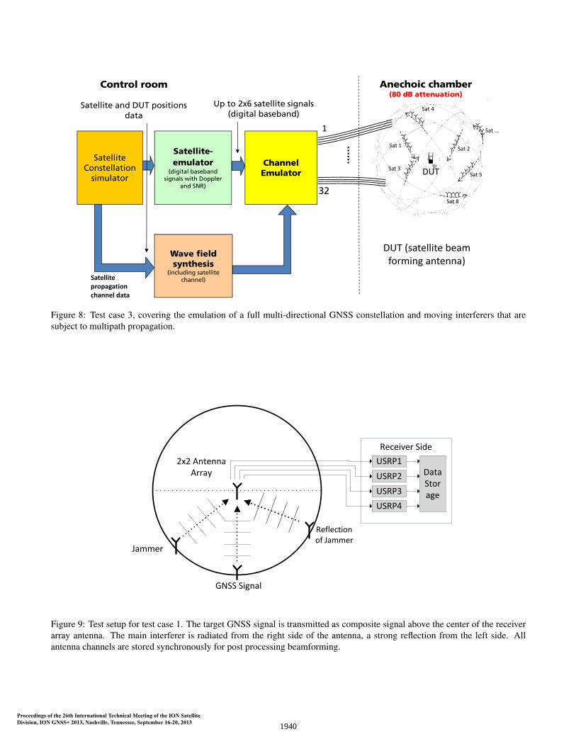
Test case 3: Jammer & spoofer in a dynamicmulti-satellite GNSS emulation
The full three-dimensional emulation of the entire GNSSscenario, including the emulation of each individual GNSSsatellite and its orbit, as is shown in Figure 8, is most chal-lenging. However, it can be assumed that for one satellitethe emulation accuracy of the WFS is the same as the simu-lations shown in the previous test cases. Based on these re-sults a fixed constellation of satellites applying one or moreOTA illumination antennas for each satellite is already pos-sible. However, currently it is analysed in which way theOTA illumination antennas have to be placed in a three di-mensional hemisphere to achieve a sufficient emulation ac-curacy for multiple satellites on changing orbit positions.The aim is to emulate up to 6 satellites on two frequencybands or 12 on one. As a jamming source in this scenario acommercially available privacy protection device could beused and placed anywhere in the anechoic chamber. BothGNSS beamsteering algorithms to track single satellites aswell as the nulling of interferers can be tested. In a similarway, a potential spoofer can be simulated, by transmittinga composite GNSS signal from a single OTA illuminationantenna.
PROOF OF CONCEPT WITH A DIRECTIONALGNSS TEST RECEIVER
In this Section preliminary results with respect to test case2 are presented. The goal is to prove the general test princi-ple and the feasibility to test beamforming algorithms andreceiver in this test environment.
In this test case, the ability of a beamforming GNSS re-ceiver to track the individual GNSS satellites is neglected.
Instead, the goal of this test is to assess the performanceof interference mitigation. The target GPS signal was ra-diated as composite signal from a single OTA illuminationantenna at 1575.42 MHz (L1 frequency band). From the ar-ray antenna’s point of view, this target signal was radiatedat an elevation of θ = 87◦, since the array was placed nor-mal to the OTA antenna plane (i.e. the arrays x − y planeis the z − y plane of the OTA illumination antenna ring).
The interferer was radiated from two different directions(see Figure 9). The main jammer was placed at an elevationθ of about 43 ◦, with a transmit power of 15 dB above thedesired Global Positioning System (GPS) signal. To sim-ulate a strong reflection, the same interference signal wastransmitted from θ = 30 ◦, still 5 dB above the GPS signal.The total duration of interference was ∼ 5 s, in which theGPS signal was completely jammed. In this scenario onlya static environment was emulated, i.e. the jammers werenot moving.
The GNSS beamforming test receiver comprised a 2×2 ac-tive antenna array in combination with four Universal Soft-ware Radio Peripherals (USRPs) 4. All four signals fromthe antenna array were captured phase synchronously anddigitized by the USRPs for post analysis and processing.
The GPS test sequence was obtained from the Spirent GNSSSimulator GSS80005, available at Fraunhofer IIS using theFlexiband USB recording front-end [10]. Both, GPS testsignal and jammer were 5 MHz wide. The jammer itselfwas modelled as multi tone signal with 224 frequency bins,which leads to a period length of 44.8µs. This test sig-nal may oppose typical jammers, that can be classified asnarrow-/wideband AWGN, chirped or pulsed signals. How-ever, it was considerably chosen, as it is well suited for thecharacterization and comparison of all four antenna outputchannels.
DoA estimation
The key idea for OTA test methodologies is to emulate aplane wave inside the sweet spot surrounding the DUT fora virtual source from a specific direction. The direction oftarget signals or interferers has to be estimated by the re-ceiver prior to either steering a beam towards the source orto null it. In case of GNSS receivers, the almanac of satel-lite positions supports the DoA estimation, but interferershave to be estimated based on the signal.
As discussed previously, the synthesized wave field maydeviate to a certain extent from the ideal field, which au-tomatically affects the DoA estimation of phased array an-tennas, since the wave will not be plane over the entire ar-ray aperture. With this test setup it shall be shown that thereceiver’s antenna array ”sees” the same environment asintended. To estimate the AoA of the different sources, a
4https://www.ettus.com/product/details/UN210-KIT
5http://www.spirent.com/Products/GSS8000
1939
Scenario 3: GNSS Satellite Emulation(Q1‐Q2\2015)
Sat 3
Sat 1 Sat 2
Sat 4
Sat 5
Sat ...
Sat 8
DUT
Anechoic chamber(80 dB attenuation)
Channel Emulator
1
32
Control room
Satellite-emulator
(digital baseband signals with Doppler
and SNR)
Up to 2x6 satellite signals(digital baseband)
Satellite Constellation
simulator
Satellite and DUT positions data
Satellite propagation channel data
DUT (satellite beam forming antenna)
Wave field synthesis
(including satellite channel)
Figure 8: Test case 3, covering the emulation of a full multi-directional GNSS constellation and moving interferers that aresubject to multipath propagation.
Reflection of Jammer
GNSS Signal
Jammer
2x2 Antenna Array
Receiver Side
USRP1
USRP2
USRP3
USRP4
Data Storage
Figure 9: Test setup for test case 1. The target GNSS signal is transmitted as composite signal above the center of the receiverarray antenna. The main interferer is radiated from the right side of the antenna, a strong reflection from the left side. Allantenna channels are stored synchronously for post processing beamforming.
1940
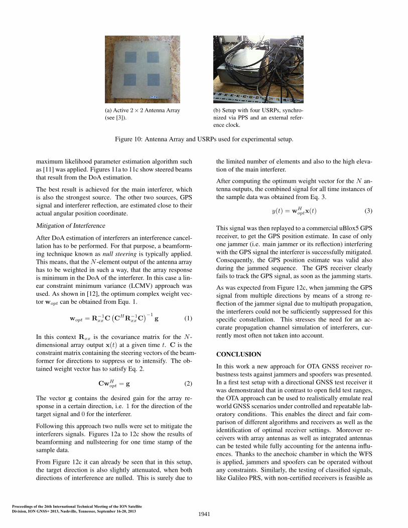
(a) Active 2× 2 Antenna Array(see [3]).
(b) Setup with four USRPs, synchro-nized via PPS and an external refer-ence clock.
Figure 10: Antenna Array and USRPs used for experimental setup.
maximum likelihood parameter estimation algorithm suchas [11] was applied. Figures 11a to 11c show steered beamsthat result from the DoA estimation.
The best result is achieved for the main interferer, whichis also the strongest source. The other two sources, GPSsignal and interferer reflection, are estimated close to theiractual angular position coordinate.
Mitigation of Interference
After DoA estimation of interferers an interference cancel-lation has to be performed. For that purpose, a beamform-ing technique known as null steering is typically applied.This means, that theN -element output of the antenna arrayhas to be weighted in such a way, that the array responseis minimum in the DoA of the interferer. In this case a lin-ear constraint minimum variance (LCMV) approach wasused. As shown in [12], the optimum complex weight vec-tor wopt can be obtained from Equ. 1.
wopt = R−1xxC
(CHR−1
xxC)−1
g (1)
In this context Rxx is the covariance matrix for the N -dimensional array output x(t) at a given time t. C is theconstraint matrix containing the steering vectors of the beam-former for directions to suppress or to intensify. The ob-tained weight vector has to satisfy Eq. 2.
CwHopt = g (2)
The vector g contains the desired gain for the array re-sponse in a certain direction, i.e. 1 for the direction of thetarget signal and 0 for the interferer.
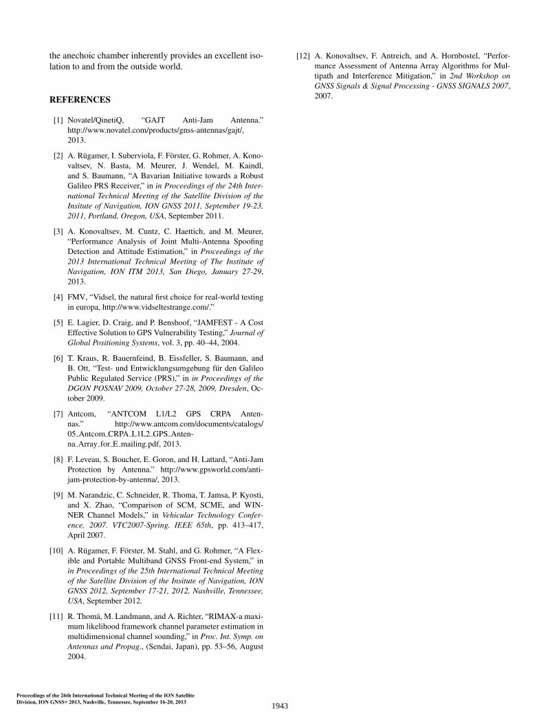
Following this approach two nulls were set to mitigate theinterferers signals. Figures 12a to 12c show the results ofbeamforming and nullsteering for one time stamp of thesample data.
From Figure 12c it can already be seen that in this setup,the target direction is also slightly attenuated, when bothdirections of interference are nulled. This is surely due to
the limited number of elements and also to the high eleva-tion of the main interferer.
After computing the optimum weight vector for the N an-tenna outputs, the combined signal for all time instances ofthe sample data was obtained from Eq. 3.
y(t) = wHoptx(t) (3)
This signal was then replayed to a commercial uBlox5 GPSreceiver, to get the GPS position estimate. In case of onlyone jammer (i.e. main jammer or its reflection) interferingwith the GPS signal the interferer is successfully mitigated.Consequently, the GPS position estimate was valid alsoduring the jammed sequence. The GPS receiver clearlyfails to track the GPS signal, as soon as the jamming starts.
As was expected from Figure 12c, when jamming the GPSsignal from multiple directions by means of a strong re-flection of the jammer signal due to multipath propagation,the interferers could not be sufficiently suppressed for thisspecific constellation. This stresses the need for an ac-curate propagation channel simulation of interferers, cur-rently most often not taken into account.
CONCLUSION
In this work a new approach for OTA GNSS receiver ro-bustness tests against jammers and spoofers was presented.In a first test setup with a directional GNSS test receiver itwas demonstrated that in contrast to open field test ranges,the OTA approach can be used to realistically emulate realworld GNSS scenarios under controlled and repeatable lab-oratory conditions. This enables the direct and fair com-parison of different algorithms and receivers as well as theidentification of optimal receiver settings. Moreover re-ceivers with array antennas as well as integrated antennascan be tested while fully accounting for the antenna influ-ences. Thanks to the anechoic chamber in which the WFSis applied, jammers and spoofers can be operated withoutany constraints. Similarly, the testing of classified signals,like Galileo PRS, with non-certified receivers is feasible as
1941
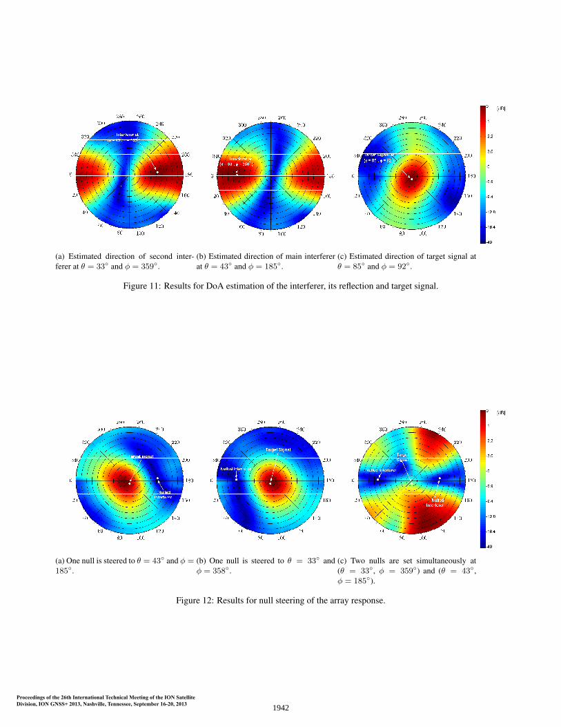
(a) Estimated direction of second inter-ferer at θ = 33◦ and φ = 359◦.
(b) Estimated direction of main interfererat θ = 43◦ and φ = 185◦.
(c) Estimated direction of target signal atθ = 85◦ and φ = 92◦.
Figure 11: Results for DoA estimation of the interferer, its reflection and target signal.
(a) One null is steered to θ = 43◦ and φ =185◦.
(b) One null is steered to θ = 33◦ andφ = 358◦.
(c) Two nulls are set simultaneously at(θ = 33◦, φ = 359◦) and (θ = 43◦,φ = 185◦).
Figure 12: Results for null steering of the array response.
1942
the anechoic chamber inherently provides an excellent iso-lation to and from the outside world.
REFERENCES
[1] Novatel/QinetiQ, “GAJT Anti-Jam Antenna.”http://www.novatel.com/products/gnss-antennas/gajt/,2013.
[2] A. Rugamer, I. Suberviola, F. Forster, G. Rohmer, A. Kono-valtsev, N. Basta, M. Meurer, J. Wendel, M. Kaindl,and S. Baumann, “A Bavarian Initiative towards a RobustGalileo PRS Receiver,” in in Proceedings of the 24th Inter-national Technical Meeting of the Satellite Division of theInsitute of Navigation, ION GNSS 2011, September 19-23,2011, Portland, Oregon, USA, September 2011.
[3] A. Konovaltsev, M. Cuntz, C. Haettich, and M. Meurer,“Performance Analysis of Joint Multi-Antenna SpoofingDetection and Attitude Estimation,” in Proceedings of the2013 International Technical Meeting of The Institute ofNavigation, ION ITM 2013, San Diego, January 27-29,2013.
[4] FMV, “Vidsel, the natural first choice for real-world testingin europa, http://www.vidseltestrange.com/.”
[5] E. Lagier, D. Craig, and P. Benshoof, “JAMFEST - A CostEffective Solution to GPS Vulnerability Testing,” Journal ofGlobal Positioning Systems, vol. 3, pp. 40–44, 2004.
[6] T. Kraus, R. Bauernfeind, B. Eissfeller, S. Baumann, andB. Ott, “Test- und Entwicklungsumgebung fur den GalileoPublic Regulated Service (PRS),” in in Proceedings of theDGON POSNAV 2009, October 27-28, 2009, Dresden, Oc-tober 2009.
[7] Antcom, “ANTCOM L1/L2 GPS CRPA Anten-nas.” http://www.antcom.com/documents/catalogs/05 Antcom CRPA L1L2 GPS Anten-na Array for E mailing.pdf, 2013.
[8] F. Leveau, S. Boucher, E. Goron, and H. Lattard, “Anti-JamProtection by Antenna.” http://www.gpsworld.com/anti-jam-protection-by-antenna/, 2013.
[9] M. Narandzic, C. Schneider, R. Thoma, T. Jamsa, P. Kyosti,and X. Zhao, “Comparison of SCM, SCME, and WIN-NER Channel Models,” in Vehicular Technology Confer-ence, 2007. VTC2007-Spring. IEEE 65th, pp. 413–417,April 2007.
[10] A. Rugamer, F. Forster, M. Stahl, and G. Rohmer, “A Flex-ible and Portable Multiband GNSS Front-end System,” inin Proceedings of the 25th International Technical Meetingof the Satellite Division of the Insitute of Navigation, IONGNSS 2012, September 17-21, 2012, Nashville, Tennessee,USA, September 2012.
[11] R. Thoma, M. Landmann, and A. Richter, “RIMAX-a maxi-mum likelihood framework channel parameter estimation inmultidimensional channel sounding,” in Proc. Int. Symp. onAntennas and Propag., (Sendai, Japan), pp. 53–56, August2004.
[12] A. Konovaltsev, F. Antreich, and A. Hornbostel, “Perfor-mance Assessment of Antenna Array Algorithms for Mul-tipath and Interference Mitigation,” in 2nd Workshop onGNSS Signals & Signal Processing - GNSS SIGNALS 2007,2007.
1943