gettingstarted - elektronikladen microcomputer · co-operative multitasking ... data input using...
TRANSCRIPT

United States:1501 10th Street, Suite 110Plano, Texas 75074USAPhone +1 972 312 1107FAX +1 972 312 1159
Europe:Bretonischer Ring 1685630 GrasbrunnGermanyPhone +49 89 / 45 60 40 - 20FAX +49 89 / 46 81 62
www.keil.comwww.keil.com
Getting
StartedBuilding
Applications
with
RL-A
RM
Getting Started
For ARM Processor-Based Microcontrollers
Building Applications with RL-ARM

2 Preface
Information in this document is subject to change without notice and does not represent a commitment on the part of the manufacturer. The software described in this document is furnished under license agreement or nondisclosure agreement and may be used or copied only in accordance with the terms of the agreement. It is against the law to copy the software on any medium except as specifically allowed in the license or nondisclosure agreement. The purchaser may make one copy of the software for backup purposes. No part of this manual may be reproduced or transmitted in any form or by any means, electronic or mechanical, including photocopying, recording, or information storage and retrieval systems, for any purpose other than for the purchaser’s personal use, without written permission. Copyright © 1997-2009 ARM Ltd and ARM Germany GmbH. All rights reserved.
Keil, the Keil Software Logo, µVision, MDK-ARM, RL-ARM, ULINK, and Device Database are trademarks or registered trademarks of ARM Ltd, and ARM Inc.
Microsoft® and Windows™ are trademarks or registered trademarks of Microsoft Corporation.
NOTE This manual assumes that you are familiar with Microsoft® Windows™ and the hardware and instruction set of the ARM7™ and ARM9™ processor families or the Cortex™-M series processors. In addition, basic knowledge of µVision®4 is anticipated.
Every effort was made to ensure accuracy in this manual and to give appropriate credit to persons, companies, and trademarks referenced herein.

Getting Started: Building Applications with RL-ARM 3
Preface This manual is an introduction to the Real-Time Library (RL-ARM™), which is a group of tightly coupled libraries designed to solve the real-time and communication challenges of embedded systems based on ARM processor-based microcontroller devices.
Using This Book This book comes with a number of practical exercises that demonstrate the key operating principles of the RL-ARM. To use the exercises you will need to have both the Keil™ Microcontroller Development Kit (MDK-ARM™) installed and the Real-Time Library (RL-ARM). If you are new to the MDK-ARM, there is a separate Getting Started guide, which will introduce you to the key features. The online documentation for the MDK-ARM, including the Getting Started guide, is located at www.keil.com/support/man_arm.htm.
Alongside the standard RL-ARM examples, this book includes a number of additional examples. These examples present the key principles outlined in this book using the minimal amount of code. Each example is designed to be built with the evaluation version of the MDK-ARM. If this is not possible, the example is prebuilt so that it can be downloaded and run on a suitable evaluation board.
This book is useful for students, beginners, advanced and experienced developers alike.
However, it is assumed that you have a basic knowledge of how to use microcontrollers and that you are familiar with the instruction set of your preferred microcontroller. In addition, it is helpful to have basic knowledge on how to use the µVision Debugger & IDE.

4 Preface
Chapter Overview
“Chapter 1. Introduction”, provides a product overview, remarks referring to the installation requirements, and shows how to get support from the Keil technical support team.
“Chapter 2. Developing with an RTOS”, describes the advantages of the RTX, explains the RTX kernel, and addresses RTOS features, such as tasks, semaphores, mutexes, time management, and priority schemes.
“Chapter 3. RL-Flash Introduction”, describes the features of the embedded file system, how to set it up, configuration options, standard routines used to maintain the file system, and how to adapt flash algorithms.
“Chapter 4. RL-TCPnet Introduction”, describes the network model, TCP key features, communication protocols, and how to configure an ARM processor-based microcontroller to function with HTTP, Telnet, FTP, SMTP, or DNS applications.
“Chapter 5. RL-USB Introduction”, describes the USB key features, the physical and logical network, pipes and endpoints, the device communication descriptors, and the supported interfaces and their classes.
“Chapter 6. RL-CAN Introduction”, describes the CAN key concepts, the message frame, and the programming API implemented.
Getting Started: Building Applications with RL-ARM 5
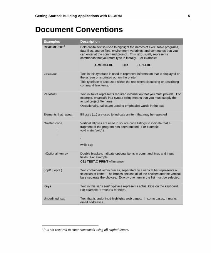
Document Conventions Examples Description README.TXT1 Bold capital text is used to highlight the names of executable programs,
data files, source files, environment variables, and commands that you can enter at the command prompt. This text usually represents commands that you must type in literally. For example: ARMCC.EXE DIR LX51.EXE
Courier Text in this typeface is used to represent information that is displayed on the screen or is printed out on the printer This typeface is also used within the text when discussing or describing command line items.
Variables Text in italics represents required information that you must provide. For example, projectfile in a syntax string means that you must supply the actual project file name Occasionally, italics are used to emphasize words in the text.
Elements that repeat… Ellipses (…) are used to indicate an item that may be repeated
Omitted code . . .
Vertical ellipses are used in source code listings to indicate that a fragment of the program has been omitted. For example: void main (void) { . . . while (1);
«Optional Items» Double brackets indicate optional items in command lines and input fields. For example: C51 TEST.C PRINT «filename»
{ opt1 | opt2 } Text contained within braces, separated by a vertical bar represents a selection of items. The braces enclose all of the choices and the vertical bars separate the choices. Exactly one item in the list must be selected.
Keys Text in this sans serif typeface represents actual keys on the keyboard. For example, “Press F1 for help”.
Underlined text Text that is underlined highlights web pages. In some cases, it marks email addresses.
1It is not required to enter commands using all capital letters.

6 Content
Content Preface ................................................................................................................... 3
Document Conventions ........................................................................................ 5
Content .................................................................................................................. 6
Chapter 1. Introduction .................................................................................... 10 RL-ARM Overview ......................................................................................... 10 RTX RTOS ...................................................................................................... 11 Flash File System ............................................................................................. 11 TCP/IP ............................................................................................................. 12 USB .................................................................................................................. 12 CAN ................................................................................................................. 13 Installation ....................................................................................................... 14 Product Folder Structure .................................................................................. 14 Last-Minute Changes ....................................................................................... 15 Requesting Assistance ..................................................................................... 15
Chapter 2. Developing With an RTOS ........................................................... 16 Getting Started ................................................................................................. 16 Setting-Up a Project ......................................................................................... 17 RTX Kernel ..................................................................................................... 19 Tasks ................................................................................................................ 19 Starting RTX .................................................................................................... 21 Creating Tasks ................................................................................................. 22 Task Management ............................................................................................ 24 Multiple Instances ............................................................................................ 24 Time Management ........................................................................................... 24 Time Delay ...................................................................................................... 25 Periodic Task Execution .................................................................................. 26 Virtual Timer ................................................................................................... 26 Idle Demon ...................................................................................................... 27 Inter-Task Communication .............................................................................. 28 Events .............................................................................................................. 28 RTOS Interrupt Handling ................................................................................ 29 Task Priority Scheme ....................................................................................... 31 Semaphores ...................................................................................................... 32 Using Semaphores ........................................................................................... 34 Signaling .......................................................................................................... 34 Multiplex .......................................................................................................... 34

Getting Started: Building Applications with RL-ARM 7
Rendezvous ...................................................................................................... 35 Barrier Turnstile ............................................................................................... 36 Semaphore Caveats .......................................................................................... 38 Mutex ............................................................................................................... 38 Mutex Caveats ................................................................................................. 39 Mailbox ............................................................................................................ 39 Task Lock and Unlock ..................................................................................... 43 Configuration ................................................................................................... 43 Task Definitions ............................................................................................... 44 System Timer Configuration ........................................................................... 45 Round Robin Task Switching .......................................................................... 45 Scheduling Options .......................................................................................... 45 Pre-emptive Scheduling ................................................................................... 46 Round Robin Scheduling ................................................................................. 46 Round Robin Pre-emptive Scheduling ............................................................ 47 Co-operative Multitasking ............................................................................... 47 Priority Inversion ............................................................................................. 47
Chapter 3. RL-Flash Introduction .................................................................. 49 Getting Started ................................................................................................. 49 Setting-Up the File System .............................................................................. 50 File I/O Routines .............................................................................................. 52 Volume Maintenance Routines ........................................................................ 54 Flash Drive Configuration ............................................................................... 56 Adapting Flash Algorithms for RL-Flash ........................................................ 58 MultiMedia Cards ............................................................................................ 60 Serial Flash ...................................................................................................... 62
Chapter 4. RL-TCPnet Introduction .............................................................. 63 TCP/IP – Key Concepts ................................................................................... 63 Network Model ................................................................................................ 63 Ethernet and IEEE 802.3 ................................................................................. 65 TCP/IP Datagrams ........................................................................................... 65 Internet Protocol .............................................................................................. 65 Address Resolution Protocol ........................................................................... 66 Subnet Mask .................................................................................................... 67 Dynamic Host Control Protocol DHCP ........................................................... 68 Internet Control Message Protocol .................................................................. 68 Transmission Control Protocol ........................................................................ 69 User Datagram Protocol................................................................................... 70 Sockets ............................................................................................................. 70 First Project - ICMP PING .............................................................................. 71

8 Content
Debug Support ................................................................................................. 74 Using RL-TCPnet with RTX ........................................................................... 74 RL-TCPnet Applications ................................................................................. 76 Trivial File Transfer ......................................................................................... 76 Adding the TFTP Service ................................................................................ 76 HTTP Server .................................................................................................... 77 Web Server Content ......................................................................................... 78 Adding Web Pages........................................................................................... 78 Adding HTML as C Code ................................................................................ 79 Adding HTML with RL-Flash ......................................................................... 81 The Common Gateway Interface ..................................................................... 82 Dynamic HTML .............................................................................................. 82 Data Input Using Web Forms .......................................................................... 84 Using the POST Method .................................................................................. 84 Using the GET Method .................................................................................... 87 Using JavaScript .............................................................................................. 88 AJAX Support ................................................................................................. 90 Simple Mail Transfer Client ............................................................................ 94 Adding SMTP Support .................................................................................... 94 Sending a Fixed Email Message ...................................................................... 95 Dynamic Message ............................................................................................ 96 Telnet Server .................................................................................................... 98 Telnet Helper Functions ................................................................................. 100 DNS Client ..................................................................................................... 101 Socket Library ............................................................................................... 102 User Datagram Protocol (UDP) Communication .......................................... 103 Transmission Control Protocol (TCP) Communication................................. 105 Deployment .................................................................................................... 108 Serial Drivers ................................................................................................. 109
Chapter 5. RL-USB Introduction .................................................................. 111 The USB Protocol – Key Concepts ............................................................... 111 USB Physical Network .................................................................................. 111 Logical Network ............................................................................................ 112 USB Pipes And Endpoints ............................................................................. 113 Interrupt Pipe ................................................................................................. 115 Isochronous Pipe ............................................................................................ 115 Bulk Pipe ....................................................................................................... 115 Bandwidth Allocation .................................................................................... 116 Device Configuration ..................................................................................... 117 Device Descriptor .......................................................................................... 118 Configuration Descriptor ............................................................................... 119

Getting Started: Building Applications with RL-ARM 9
Interface Descriptor ....................................................................................... 120 Endpoint Descriptor ....................................................................................... 121 RL-USB ......................................................................................................... 122 RL-USB Driver Overview ............................................................................. 122 First USB Project ........................................................................................... 124 Configuration ................................................................................................. 124 Event Handlers ............................................................................................... 125 USB Descriptors ............................................................................................ 126 Class Support ................................................................................................. 127 Human Interface Device ................................................................................ 128 HID Report Descriptors ................................................................................. 128 HID Client ..................................................................................................... 133 Enlarging the IN & OUT Endpoint Packet Sizes ........................................... 134 Mass Storage .................................................................................................. 136 Audio Class .................................................................................................... 138 Composite Device .......................................................................................... 139 Compliance Testing ....................................................................................... 140
Chapter 6. RL-CAN Introduction ................................................................. 141 The CAN Protocol – Key Concepts ............................................................... 141 CAN Node Design ......................................................................................... 142 CAN Message Frames ................................................................................... 143 CAN Bus Arbitration ..................................................................................... 145 RL-CAN Driver ............................................................................................. 146 First Project .................................................................................................... 146 CAN Driver API ............................................................................................ 147 Basic Transmit and Receive .......................................................................... 148 Remote Request ............................................................................................. 149 Object Buffers ................................................................................................ 151
Glossary ............................................................................................................ 152

10 Chapter 1. Introduction
Chapter 1. Introduction The last few years have seen an explosive growth in both the number and complexity of ARM processor-based microcontrollers. This diverse base of devices now offers the developer a suitable microcontroller for almost all applications. However, this rise in sophisticated hardware also calls for more and more complex software. With ever-shorter project deadlines, it is becoming just about impossible to develop the software to drive these devices without the use of third-party middleware.
The Keil Real-Time Library (RL-ARM) is a collection of easy-to-use middleware components that are designed to work across many different microcontrollers. This allows you to learn the software once and then use it multiple times. The RL-ARM middleware integrates into the Keil Microcontroller Development Kit (MDK-ARM).
RTX RTOS Source Code
TCPnet Networking Suite
Flash File System
USB Device Interface
CAN Interface
RTOS and Middleware Components
Exa
mpl
es a
nd T
empl
ates
These two development tools allow you to rapidly develop sophisticated software applications across a vast range of ARM processor-based microcontrollers. In this book, we will look at each of the RL-ARM middleware components and see how to use all the key features in typical applications.
RL-ARM Overview The RL-ARM library consists of five main components; a Flash-based file system, a TCP/IP networking suite, drivers for USB and CAN, and the RTX Kernel. Each of the middleware components is designed to be used with the Keil RTX real-time operating system. However, with the exception of the CAN driver, each component may be used without RTX.

Getting Started: Building Applications with RL-ARM 11
RTX RTOS Traditionally developers of small, embedded applications have had to write virtually all the code that runs on the microcontroller. Typically, this is in the form of interrupt handlers with a main background-scheduling loop. While there is nothing intrinsically wrong with this, it does rather miss the last few decades of advancement in program structure and design. Now, for the first time, with the introduction of 32-bit ARM processor-based microcontrollers we have low-cost, high-performance devices with increasingly large amounts of internal SRAM and Flash memory. This makes it possible to use more advanced software development techniques. Introducing a Real-Time Operating System (RTOS) or real-time executive into your project development is an important step in the right direction. With an RTOS, all the functional blocks of your design are developed as tasks, which are then scheduled by RTX. This forces a detailed design analysis and consideration of the final program structure at the beginning of the development. Each of the program tasks can be developed, debugged, and tested in isolation before integration into the full system. Each RTOS task is then easier to maintain, document, and reuse. However, using an RTOS is only half the story. Increasingly, customers want products that are more complex in shorter and shorter time. While microcontrollers with suitable peripherals are available, the challenge is to develop applications without spending months writing the low-level driver code.
Flash File System The RL-Flash file system allows you to place a PC-compatible file system in any region of a microcontroller’s memory. This includes the on-chip and external RAM and Flash memory, as well as SPI based Flash memory and SD/MMC memory cards.
12 Chapter 1. Introduction
The RL-Flash file system comes with all the driver support necessary, including low-level Flash drivers, SPI drivers, and MultiMedia Card interface drivers. This gets the file system up-and-running with minimal fuss and allows you to concentrate on developing your application software. In the past, the use of a full file system in a small, embedded microcontroller has been something of a luxury. However, once you start developing embedded firmware with access to a small file system, you will begin to wonder how you ever managed without it!
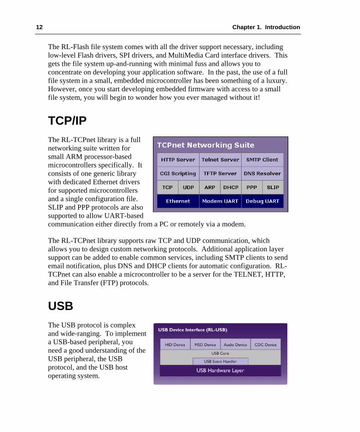
TCP/IP The RL-TCPnet library is a full networking suite written for small ARM processor-based microcontrollers specifically. It consists of one generic library with dedicated Ethernet drivers for supported microcontrollers and a single configuration file. SLIP and PPP protocols are also supported to allow UART-based communication either directly from a PC or remotely via a modem.
The RL-TCPnet library supports raw TCP and UDP communication, which allows you to design custom networking protocols. Additional application layer support can be added to enable common services, including SMTP clients to send email notification, plus DNS and DHCP clients for automatic configuration. RL-TCPnet can also enable a microcontroller to be a server for the TELNET, HTTP, and File Transfer (FTP) protocols.
USB The USB protocol is complex and wide-ranging. To implement a USB-based peripheral, you need a good understanding of the USB peripheral, the USB protocol, and the USB host operating system.

Getting Started: Building Applications with RL-ARM 13
Typically, the host will be a PC. This means that you need to have a deep knowledge of the Windows operating system and its device drivers. Getting all of these elements working together would be a development project in its own. Like the TCP/IP library, the RL-USB driver is a common software stack designed to work across all supported microcontrollers. Although you can use the RL-USB driver to communicate with a custom Windows device driver, it has been designed to support common USB classes. Each USB class has its own native driver within the Windows operating system. This means that you do not need to develop or maintain your own driver.
The class support provided with RL-USB includes Human Interface Device (HID), Mass Storage Class (MSC), Communication Device Class (CDC), and Audio Class. The HID Class allows you to exchange custom control and configuration data with your device. The Mass Storage Class allows the Windows operating system to access the data stored within the RL-Flash file system in the same manner as a USB pen drive. The Communication Device Class can be used to realize a virtual COM Port. Finally, the Audio Class allows you to exchange streaming audio data between the device and a PC. Together these four classes provide versatile support for most USB design requirements.
CAN The RL-CAN driver is the one component of the RL-ARM library that is tightly coupled to the RTX. The CAN driver consists of just six functions that allow you to initialize a given CAN peripheral, define, transmit and receive CAN message objects, and exchange data with other nodes on the CAN network.
The RL-CAN driver has a consistent programming API for all supported CAN peripherals, allowing easy migration of code or integration of several different microcontrollers into the one project. The CAN driver also uses RTX message queues to buffer, transmit and receive messages, ensuring ordered handling of the CAN network data.

14 Chapter 1. Introduction
Installation The RL-ARM is a collection of middleware components designed to integrate with the Keil Microcontroller Development Kit (MDK-ARM). To use this book you will need to have both the MDK-ARM and RL-ARM installed on your PC. MDK-ARM may be installed from either CD-ROM, or may be downloaded from the web. Currently, RL-ARM may only be downloaded from the web.
Keil products are available on CD-ROM and via download from www.keil.com. Updates to the related products are regularly available at www.keil.com/update. Demo versions of various products are obtainable at www.keil.com/demo. Additional information is provided under www.keil.com/arm.
Please check the minimum hardware and software requirements that must be satisfied to ensure that your Keil development tools are installed and will function properly. Before attempting installation, verify that you have:
A standard PC running Microsoft Windows XP, or Windows Vista, 1GB RAM and 500 MB of available hard-disk space is recommended, 1024x768 or higher screen resolution; a mouse or other pointing device, A CD-ROM drive.
Product Folder Structure The SETUP program copies the development tools into subfolders. The base folder defaults to C:\KEIL. When the RL-ARM is installed, it integrates into the MDK-ARM installation. The table below outlines the key RL-ARM files:
File Type Path
MDK-ARM Toolset C:\KEIL\ARM Include and Header Files C:\KEIL\ARM\RVxx\INC Libraries C:\KEIL\ARM\RVxx\LIB Source Code C:\KEIL\ARM\RL Standard Examples C:\KEIL\ARM\Boards\manufacturer\board Flash Programming C:\KEIL\ARM\FLASH On-line Help Files and Release Notes C:\KEIL\ARM\HLP

Getting Started: Building Applications with RL-ARM 15
Last-Minute Changes As with any high-tech product, last minute changes might not be included into the printed manuals. These last-minute changes and enhancements to the software and manuals are listed in the Release Notes shipped with the product.
Requesting Assistance At Keil, we are committed to providing you with the best-embedded development tools, documentation, and support. If you have suggestions and comments regarding any of our products, or you have discovered a problem with the software, please report them to us, and where applicable make sure to:
1. Read the section in this manual that pertains to the task you are attempting,
2. Check the update section of the Keil web site to make sure you have the latest software and utility version,
3. Isolate software problems by reducing your code to as few lines as possible.
If you are still having difficulties, please report them to our technical support group. Make sure to include your license code and product version number displayed through the Help – About Menu of µVision. In addition, we offer the following support and information channels, accessible at ww.keil.com/support.
1. The Support Knowledgebase is updated daily and includes the latest questions and answers from the support department,
2. The Application Notes can help you in mastering complex issues, like interrupts and memory utilization,
3. Check the on-line Discussion Forum,
4. Request assistance through Contact Technical Support (web-based E-Mail),
5. Finally, you can reach the support department directly via [email protected] or [email protected].

16 Chapter 2. Developing With an RTOS
Chapter 2. Developing With an RTOS In the course of this chapter we will consider the idea of using RTX, the Keil small footprint RTOS, on an ARM processor-based microcontroller. If you are used to writing procedural-based C code on microcontrollers, you may doubt the need for such an operating system. If you are not familiar with using an RTOS in real-time embedded systems, you should read this chapter before dismissing the idea. The use of an RTOS represents a more sophisticated design approach, inherently fostering structured code development, which is enforced by the RTOS Application Programming Interface (API).
The RTOS structure allows you to take an object-orientated design approach while still programming in C. The RTOS also provides you with multithreaded support on a small microcontroller. These two features create a shift in design philosophy, moving us away from thinking about procedural C code and flow charts. Instead, we consider the fundamental program tasks and the flow of data between them. The use of an RTOS also has several additional benefits, which may not be immediately obvious. Since an RTOS-based project is composed of well-defined tasks, using an RTOS helps to improve project management, code reuse, and software testing.
The tradeoff for this is that an RTOS has additional memory requirements and increased interrupt latency. Typically, RTX requires between 500 Bytes and 5KBytes of RAM and 5KBytes of code, but remember that some of the RTOS code would be replicated in your program anyway. We now have a generation of small, low-cost microcontrollers that have enough on-chip memory and processing power to support the use of an RTOS. Developing using this approach is therefore much more accessible.
Getting Started This chapter first looks at setting up an introductory RTOS project for ARM7, ARM9, and Cortex-M based microcontrollers. Next, we will go through each of the RTOS primitives and explain how they influence the design of our application code. Finally, when we have a clear understanding of the RTOS features, we will take a closer look at the RTOS configuration file.

Getting Started: Building Applications with RL-ARM 17
Setting-Up a Project The first exercise in the examples accompanying this book provides a PDF document giving a detailed step-by-step guide for setting up an RTX project. Here we will look at the main differences between a standard C program and an RTOS-based program. First, our µVision project is defined in the default way. This means that we start a new project and select a microcontroller from the µVision Device Database®. This will add the startup code and configure the compiler, linker, simulation model, debugger, and Flash programming algorithms. Next, we add an empty C module and save it as main.c to start a C-based application. This will give us a project structure similar to that shown on the right. A minimal application program consists of an Assembler file for the startup code and a C module.
The RTX configuration is held in the file RTX_Config.c that must be added to your project. As its name implies, RTX_Config.c holds the configuration settings for RTX. This file is specific to the ARM processor-based microcontroller you are using. Different versions of the file are located in C:\KEIL\ARM\STARTUP.
If you are using an ARM7 or ARM9-based microcontroller, you can select the correct version for the microcontroller family you are using and RTX will work “out-of-the-box”. For Cortex-M-based microcontrollers there is one generic configuration file. We will examine this file in more detail later, after we have looked more closely at RTX and understood what needs to be configured.
To enable our C code to access the RTX API, we need to add an include file to all our application files that use RTX functions. To do this you must add the following include file in main.
#include <RTL.h>

18 Chapter 2. Developing With an RTOS
We must let the µVision IDE utility know that we are using RTX so that it can link in the correct library. This is done by selecting “RTX Kernel” in the Options for Target menu, obtained by right clicking on “RTOS”.
The RTX Kernel library is added to the project by selecting the operating system in the dialog Options for Target.
When using RTX with an ARM7 or ARM9 based microcontroller, calls to the RTOS are made by Software Interrupt instructions (SWI). In the default startup code, the SWI interrupt vector jumps to a tight loop, which traps SWI calls. To configure the startup code to work with RTX we must modify the SWI vector code to call RTX.
A part of RTX runs in the privileged supervisor mode and is called with software interrupts (SWI). We must therefore disable the SWI trap in the startup code. With Cortex-based microcontroller, the interrupt structure is different and does not require you to change the startup code, so you can ignore this step.
You must disable the default SWI handler and import the SWI_Handler used by the RTOS, when used with ARM7 or ARM9.
IMPORT SWI_Handler Undef_Handler B Undef_Handler ;SWI_Handler B SWI_Handler ; Part of RTL PAbt_Handler B PAbt_Handler DAbt_Handler B DAbt_Handler IRQ_Handler B IRQ_Handler FIQ_Handler B FIQ_Handler
In the vector table, the default SWI_Handler must be commented out and the SWI_Handler label must be declared as an import. Now, when RTX generates a software interrupt instruction, the program will jump to the SWI_Handler in the RTX library. These few steps are all that are required to configure a project to use RTX.
Exercise: First Project The first RTOS exercise guides you through setting up and debugging an RTX-based project.

Getting Started: Building Applications with RL-ARM 19
RTX Kernel RTX consists of a scheduler that supports round-robin, pre-emptive, and co-operative multitasking of program tasks, as well as time and memory management services. Inter-task communication is supported by additional RTOS objects, including event triggering, semaphores, Mutex, and a mailbox system. As we will see, interrupt handling can also be accomplished by prioritized tasks, which are scheduled by the RTX kernel.
The RTX kernel contains a scheduler that runs program code as tasks. Communication between tasks is accomplished by RTOS objects such as events, semaphores, Mutexes, and mailboxes. Additional RTOS services include time and memory management and interrupt support.
Tasks The building blocks of a typical C program are functions that we call to perform a specific procedure and which then return to the calling function. In an RTOS, the basic unit of execution is a “Task”. A task is very similar to a C procedure, but has some fundamental differences.
Procedure Task unsigned int procedure (void) { … … return (val); }
__task void task (void) { for (;;) { … } }
We always expect to return from C functions, however, once started an RTOS task must contain an endless loop, so that it never terminates and thus runs forever. You can think of a task as a mini self-contained program that runs within the RTOS. While each task runs in an endless loop, the task itself may be started by other tasks and stopped by itself or other tasks. A task is declared as a C function, however RTX provides an additional keyword __task that should be added to the function prototype as shown above. This keyword tells the compiler

20 Chapter 2. Developing With an RTOS
not to add the function entry and exit code. This code would normally manage the native stack. Since the RTX scheduler handles this function, we can safely remove this code. This saves both code and data memory and increases the overall performance of the final application.
An RTOS-based program is made up of a number of tasks, which are controlled by the RTOS scheduler. This scheduler is essentially a timer interrupt that allots a certain amount of execution time to each task. So task1 may run for 100ms then be de-scheduled to allow task2 to run for a similar period; task 2 will give way to task3, and finally control passes back to task1. By allocating these slices of runtime to each task in a round-robin fashion, we get the appearance of all three tasks running in parallel to each other.
Conceptually we can think of each task as performing a specific functional unit of our program, with all tasks running simultaneously. This leads us to a more object-orientated design, where each functional block can be coded and tested in isolation and then integrated into a fully running program. This not only imposes a structure on the design of our final application but also aids debugging, as a particular bug can be easily isolated to a specific task. It also aids code reuse in later projects. When a task is created, it is allocated its own task ID. This is a variable, which acts as a handle for each task and is used when we want to manage the activity of the task.
OS_TID id1, id2, id3;
Task Control Block Task Stack
Priority & State Context
Task
In order to make the task-switching process happen, we have the code overhead of the RTOS and we have to dedicate a CPU hardware timer to provide the RTOS time reference. For ARM7 and ARM9 this must be a timer provided by the microcontroller peripherals. In a Cortex-M microcontroller, RTX will use the SysTick timer within the Cortex-M processor. Each time we switch running tasks the RTOS saves the state of all the task variables to a task stack and stores the runtime information about a task in a Task Control Block. The “context switch time”, that is, the time to save the current task state and load up and start the next task, is a crucial value and will depend on both the RTOS kernel and the design of the underlying hardware.

Getting Started: Building Applications with RL-ARM 21
Each task has its own stack for saving its data during a context switch. The Task Control Block is used by the kernel to manage the active tasks.
The Task Control Block contains information about the status of a task. Part of this information is its run state. A task can be in one of four basic states, RUNNING, READY, WAITING, or INACTIVE. In a given system only one task can be running, that is, the CPU is executing its instructions while all the other tasks are suspended in one of the other states. RTX has various methods of inter-task communication: events, semaphores, and messages. Here, a task may be suspended to wait to be signaled by another task before it resumes its READY state, at which point it can be placed into RUNNING state by the RTX scheduler.
At any moment a single task may be running. Tasks may also be waiting on an OS event. When this occurs, the tasks return to the READY state and are scheduled by the kernel.
Task Description
RUNNING The currently running TASK READY TASKS ready to run WAIT DELAY TASKS halted with a time DELAY WAIT INT TASKS scheduled to run periodically WAIT OR TASKS waiting an event flag to be set WAIT AND TASKS waiting for a group event flag to be set WAIT SEM TASKS waiting for a SEMAPHORE WAIT MUT TASKS waiting for a SEMAPHORE MUTEX WAIT MBX TASKS waiting for a MAILBOX MESSAGE INACTIVE A TASK not started or detected
Starting RTX To build a simple RTX-based program, we declare each task as a standard C function and a TASK ID variable for each Task.
__task void task1 (void); __task void task2 (void); OS_TID tskID1, tskID2;
After reset, the microcontroller enters the application through the main() function, where it executes any initializing C code before calling the first RTX function to start the operating system running.

22 Chapter 2. Developing With an RTOS
void main (void) { IODIR1 = 0x00FF0000; // Do any C code you want os_sys_init (task1); // Start the RTX call the first task }
The os_sys_init () function launches RTX, but only starts the first task running. After the operating system has been initialized, control will be passed to this task. When the first task is created it is assigned a default priority. If there are a number of tasks ready to run and they all have the same priority, they will be allotted run time in a round-robin fashion. However, if a task with a higher priority becomes ready to run, the RTX scheduler will de-schedule the currently running task and start the high priority task running. This is called pre-emptive priority-based scheduling. When assigning priorities you have to be careful, because the high priority task will continue to run until it enters a WAITING state or until a task of equal or higher priority is ready to run.
Tasks of equal priority will be scheduled in a round-robin fashion. High priority tasks will pre-empt low priority tasks and enter the RUNNING state “on demand”.
Two additional calls are available to start RTX; os_sys_init_prio(task1) will start the RTOS and create the task with a user-defined priority. The second OS call is os_sys_init_user(task1, &stack, Stack_Size). This starts the RTOS and defines a user stack.
Creating Tasks Once RTX has been started, the first task created is used to start additional tasks required for the application. While the first task may continue to run, it is good programming style for this task to create the necessary additional tasks and then delete itself.
__task void task1 (void) { tskID2 = os_tsk_create (task2,0x10); // Create the second task // and assign its priority. tskID3 = os_tsk_create (task3,0x10); // Create additional tasks // and assign priorities. os_tsk_delete_self (); // End and self-delete this task }

Getting Started: Building Applications with RL-ARM 23
The first task can create further active tasks with the os_tsk_create() function. This launches the task and assigns its task ID number and priority. In the example above we have two running tasks, task2 and task3, of the same priority, which will both be allocated an equal share of CPU runtime. While the os_tsk_create() call is suitable for creating most tasks, there are some additional task creation calls for special cases.
It is possible to create a task and pass a parameter to the task on startup. Since tasks can be created at any time while RTX is running, a task can be created in response to a system event and a particular parameter can be initialized on startup.
tskID3 = os_tsk_create_ex (Task3, priority, parameter);
When each task is created, it is also assigned its own stack for storing data during the context switch. This task stack is a fixed block of RAM, which holds all the task variables. The task stacks are defined when the application is built, so the overall RAM requirement is well defined. Ideally, we need to keep this as small as possible to minimize the amount of RAM used by the application. However, some tasks may have a large buffer, requiring a much larger stack space than other tasks in the system. For these tasks, we can declare a larger task stack, rather than increase the default stack size.
static U64 stk4 [400/8];
A task can now be declared with a custom stack size by using the os_tsk_create_user() call and the dedicated stack.
tskID4 = os_tsk_create_user (Task4, priority, &stk4, sizeof (stk4));
Finally, there is a combination of both of the above task-creating calls where we can create a task with a large stack space and pass a parameter on startup.
static U64 stk5 [400/8];
tskID5 = os_tsk_create_user_ex (Tsk5, prio, &stk5, sizeof (stk5), param);
Exercise: Tasks This exercise presents the minimal code to start the RTOS and create two running tasks.

24 Chapter 2. Developing With an RTOS
Task Management Once the tasks are running, there are a small number of RTX system calls, which are used to manage the running tasks. It is possible to elevate or lower a task’s priority either from another function or from within its own code.
OS_RESULT os_tsk_prio (tskID2, priority); OS_RESULT os_tsk_prio_self (priority);
As well as creating tasks, it is also possible for a task to delete itself or another active task from the RTOS. Again we use the task ID rather than the function name of the task.
OS_RESULT = os_tsk_delete (tskID1); os_tsk_delete_self ();
Finally, there is a special case of task switching where the running task passes control to the next ready task of the same priority. This is used to implement a third form of scheduling called co-operative task switching.
os_tsk_pass (); // switch to next ready to run task
Multiple Instances One of the interesting possibilities of an RTOS is that you can create multiple running instances of the same base task code. For example, you could write a task to control a UART and then create two running instances of the same task code. Here each instance of UART_Task would manage a different UART.
tskID3_0 = os_tsk_create_ex (UART_Task, priority, UART1);
Exercise: Multiple instances This exercise creates multiple instances of one base task and passes a parameter on startup to control the functionality of each instance.
Time Management As well as running your application code as tasks, RTX also provides some timing services, which can be accessed through RTX function calls.

Getting Started: Building Applications with RL-ARM 25
Time Delay The most basic of these timing services is a simple timer delay function. This is an easy way of providing timing delays within your application. Although the RTX kernel size is quoted as 5K bytes, features such as delay loops and simple scheduling loops are often part of a non-RTOS application and would consume code bytes anyway, so the overhead of the RTOS can be less than it initially appears.
void os_dly_wait (unsigned short delay_time)
This call will place the calling task into the WAIT_DELAY state for the specified number of system timer ticks. The scheduler will pass execution to the next task in the READY state.
During their lifetime, tasks move through many states. Here, a running task is blocked by an os_dly_wait() call so it enters a WAIT state. When the delay expires, it moves to the READY state. The scheduler will place it in the RUN state. If its time slice expires, it will move back to the READY state.
When the timer expires, the task will leave the WAIT_DELAY state and move to the READY state. The task will resume running when the scheduler moves it to the RUNNING state. If the task then continues executing without any further blocking OS calls, it will be de-scheduled at the end of its time slice and be placed in the READY state, assuming another task of the same priority is ready to run.
Exercise: Time Management This exercise replaces the user delay loops with the OS delay function.

26 Chapter 2. Developing With an RTOS
Periodic Task Execution We have seen that the scheduler runs tasks with a round-robin or pre-emptive scheduling scheme. With the timing services, it is also possible to run a selected task at specific time intervals. Within a task, we can define a periodic wake-up interval.
void os_itv_set (unsigned short interval_time)
Then we can put the task to sleep and wait for the interval to expire. This places the task into the WAIT_INT state.
void os_itv_wait (void)
When the interval expires, the task moves from the WAIT_INT to the READY state and will be placed into the RUNNING state by the scheduler.
Exercise: Interval This exercise modifies the two-task example to use interval service so that both tasks run at a fixed period.
Virtual Timer As well as running tasks on a defined periodic basis, we can define any number of virtual timers, which act as countdown timers. When they expire, they run a user call-back function to perform a specific action. A virtual timer is created with the os_timer_create() function. This system call specifies the number of RTOS system timer ticks before it expires and a value “info”, which is passed to the callback function to identify the timer. Each virtual timer is also allocated an OS_ID handle, so that it can be managed by other system calls.
OS_ID os_tmr_create (unsigned short tcnt, unsigned short info)
When the timer expires, it calls the function os_tmr_call(). The prototype for this function is located in the RTX_Config.c file.

Getting Started: Building Applications with RL-ARM 27
void os_tmr_call (U16 info) { switch (info) { case 0x01: … // user code here break ; } }
This function knows which timer has expired by reading the info parameter. We can then run the appropriate code after the “case” statement.
Exercise: Timer This exercise modifies the two-task-program to use virtual timers to control the rate at which the LEDs flash.
Idle Demon The final timer service provided by RTX is not really a timer, but this is probably the best place to discuss it. If, during our RTOS program, there is no task running and no task ready to run (e.g. they are all waiting on delay functions), then RTX uses the spare runtime to call an “Idle Demon” that is located in the RTX_Config.c file. This idle code is in effect a low priority task within the RTOS, which only runs when nothing else is ready.
__task void os_idle_demon (void) { for (;;) { … // user code here } }
You can add any code to this task, but it has to obey the same rules as user tasks.
Exercise: Idle Demon This example demonstrates how to add code to the idle task, so that the application can perform “book keeping” tasks in the spare cycles not consumed by the main application.
28 Chapter 2. Developing With an RTOS
Inter-Task Communication So far we have seen how application code can be written as independent tasks and how we can access the timing services provided by RTX. In a real application, we need to be able to communicate between tasks in order to make an application useful. To enable this, a typical RTOS supports several different communication objects, which can be used to link the tasks together to form a meaningful program. RTX supports inter-task communication with events, semaphores, mutexes, and mailboxes.
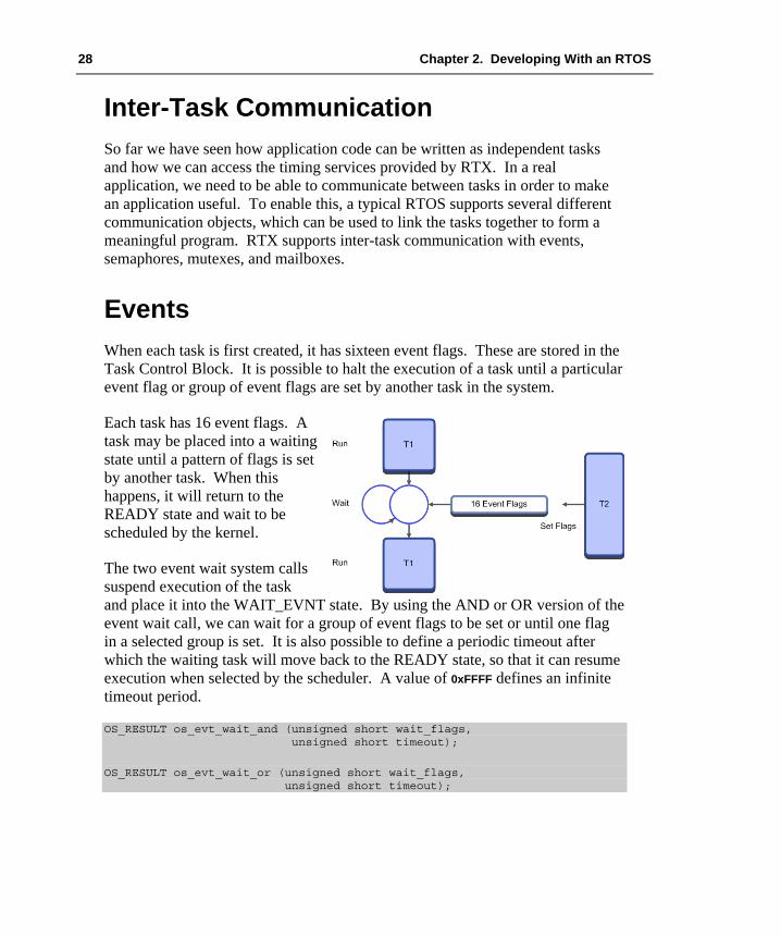
Events When each task is first created, it has sixteen event flags. These are stored in the Task Control Block. It is possible to halt the execution of a task until a particular event flag or group of event flags are set by another task in the system.
Each task has 16 event flags. A task may be placed into a waiting state until a pattern of flags is set by another task. When this happens, it will return to the READY state and wait to be scheduled by the kernel.
The two event wait system calls suspend execution of the task and place it into the WAIT_EVNT state. By using the AND or OR version of the event wait call, we can wait for a group of event flags to be set or until one flag in a selected group is set. It is also possible to define a periodic timeout after which the waiting task will move back to the READY state, so that it can resume execution when selected by the scheduler. A value of 0xFFFF defines an infinite timeout period.
OS_RESULT os_evt_wait_and (unsigned short wait_flags, unsigned short timeout);
OS_RESULT os_evt_wait_or (unsigned short wait_flags, unsigned short timeout);
Getting Started: Building Applications with RL-ARM 29
Any task can set the event flags of any other task in a system with the os_evt_set() RTX function call. We use the task ID to select the task.
void os_evt_set (unsigned short event_flags, OS_TID task);
As well as setting a task’s event flags, it is also possible to clear selected flags.
void os_evt_clr (U16 clear_flags, OS_TID task);
When a task resumes execution after it has been waiting for an os_evt_wait_or() function to complete, it may need to determine which event flag has been set. The os_evt_get() function allows you to determine the event flag that was set. You can then execute the correct code for this condition.
which_flag = os_evt_get ();
Exercise: Events This exercise extends the simple two-task-example and uses event flags to synchronize the activity between the active tasks.
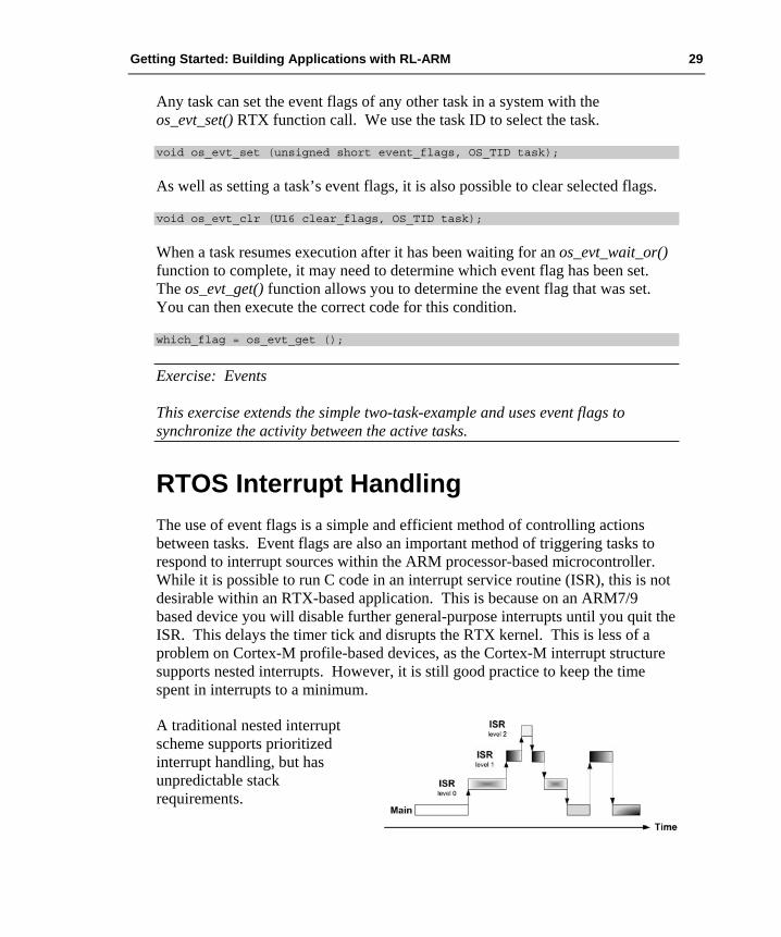
RTOS Interrupt Handling The use of event flags is a simple and efficient method of controlling actions between tasks. Event flags are also an important method of triggering tasks to respond to interrupt sources within the ARM processor-based microcontroller. While it is possible to run C code in an interrupt service routine (ISR), this is not desirable within an RTX-based application. This is because on an ARM7/9 based device you will disable further general-purpose interrupts until you quit the ISR. This delays the timer tick and disrupts the RTX kernel. This is less of a problem on Cortex-M profile-based devices, as the Cortex-M interrupt structure supports nested interrupts. However, it is still good practice to keep the time spent in interrupts to a minimum.
A traditional nested interrupt scheme supports prioritized interrupt handling, but has unpredictable stack requirements.
30 Chapter 2. Developing With an RTOS
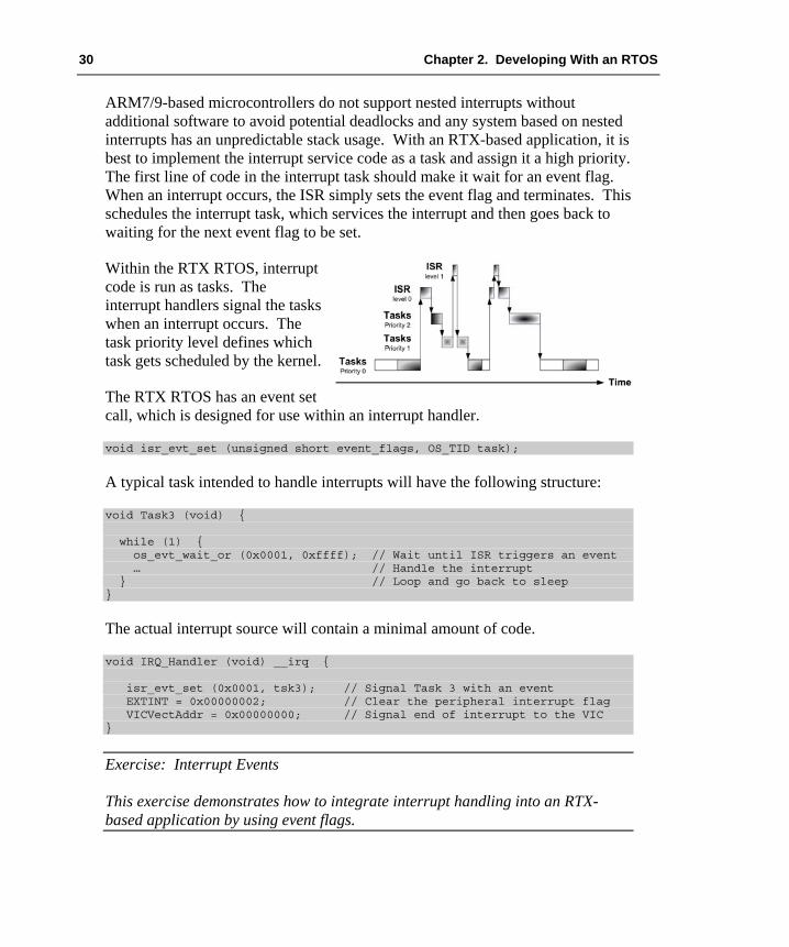
ARM7/9-based microcontrollers do not support nested interrupts without additional software to avoid potential deadlocks and any system based on nested interrupts has an unpredictable stack usage. With an RTX-based application, it is best to implement the interrupt service code as a task and assign it a high priority. The first line of code in the interrupt task should make it wait for an event flag. When an interrupt occurs, the ISR simply sets the event flag and terminates. This schedules the interrupt task, which services the interrupt and then goes back to waiting for the next event flag to be set.
Within the RTX RTOS, interrupt code is run as tasks. The interrupt handlers signal the tasks when an interrupt occurs. The task priority level defines which task gets scheduled by the kernel.
The RTX RTOS has an event set call, which is designed for use within an interrupt handler.
void isr_evt_set (unsigned short event_flags, OS_TID task);
A typical task intended to handle interrupts will have the following structure:
void Task3 (void) { while (1) { os_evt_wait_or (0x0001, 0xffff); // Wait until ISR triggers an event … // Handle the interrupt } // Loop and go back to sleep }
The actual interrupt source will contain a minimal amount of code.
void IRQ_Handler (void) __irq { isr_evt_set (0x0001, tsk3); // Signal Task 3 with an event EXTINT = 0x00000002; // Clear the peripheral interrupt flag VICVectAddr = 0x00000000; // Signal end of interrupt to the VIC }
Exercise: Interrupt Events This exercise demonstrates how to integrate interrupt handling into an RTX-based application by using event flags.
Getting Started: Building Applications with RL-ARM 31
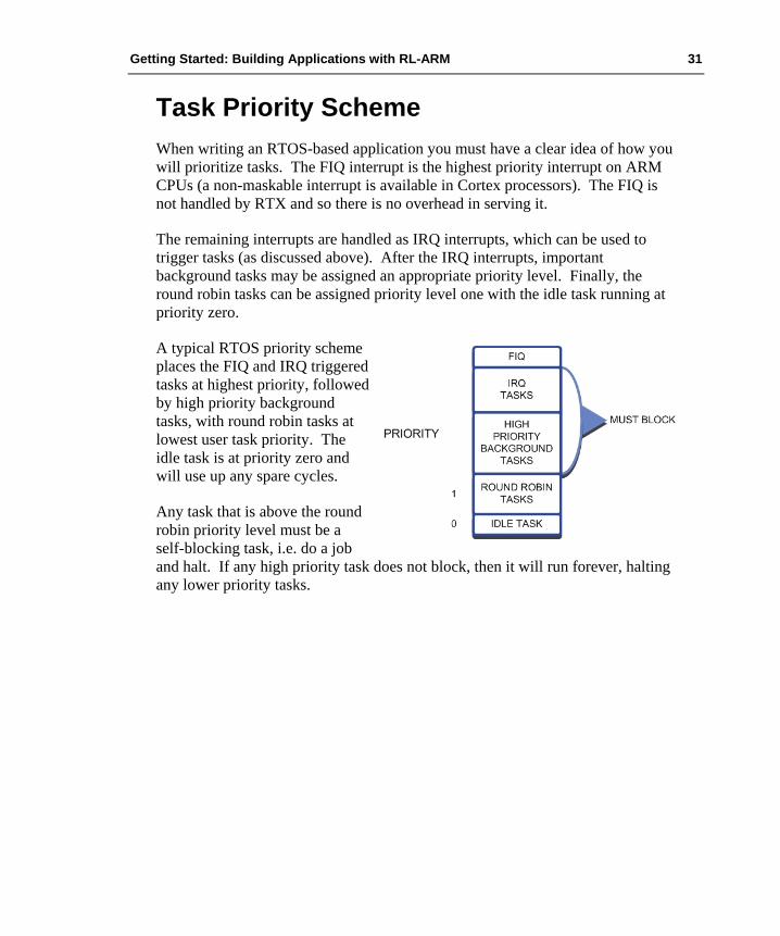
Task Priority Scheme When writing an RTOS-based application you must have a clear idea of how you will prioritize tasks. The FIQ interrupt is the highest priority interrupt on ARM CPUs (a non-maskable interrupt is available in Cortex processors). The FIQ is not handled by RTX and so there is no overhead in serving it.
The remaining interrupts are handled as IRQ interrupts, which can be used to trigger tasks (as discussed above). After the IRQ interrupts, important background tasks may be assigned an appropriate priority level. Finally, the round robin tasks can be assigned priority level one with the idle task running at priority zero.
A typical RTOS priority scheme places the FIQ and IRQ triggered tasks at highest priority, followed by high priority background tasks, with round robin tasks at lowest user task priority. The idle task is at priority zero and will use up any spare cycles.
Any task that is above the round robin priority level must be a self-blocking task, i.e. do a job and halt. If any high priority task does not block, then it will run forever, halting any lower priority tasks.

32 Chapter 2. Developing With an RTOS
Semaphores Like events, semaphores are a method of synchronizing activity between two or more tasks. Put simply, a semaphore is a container that holds a number of tokens. As a task executes, it will reach an RTOS call to acquire a semaphore token. If the semaphore contains one or more tokens, the task will continue executing and the number of tokens in the semaphore will be decremented by one. If there are currently no tokens in the semaphore, the task will be placed in a WAITING state until a token becomes available. At any point in its execution, a task may add a token to the semaphore causing its token count to increment by one.
Semaphores are used to control access to program resources. Before a task can access a resource, it must acquire a token. If none is available, it waits. When it is finished with the resource, it must return the token.
The diagram illustrates the use of a semaphore to synchronize two tasks. First, the semaphore must be created and initialized with an initial token count. In this case, the semaphore is initialized with a single token. Both tasks run and reach a point in their code where they will attempt to acquire a token from the semaphore. The first task to reach this point will acquire the token from the semaphore and continue execution. The second task will also attempt to acquire a token, but as the semaphore is empty, it will halt execution and be placed into a WAITING state until a semaphore token is available.
Meanwhile, the executing task can release a token back to the semaphore. When this happens, the waiting task will acquire the token and leave the WAITING state for the READY state. Once in the READY state, the scheduler will place the task into the RUN state so that task execution can continue. Although semaphores have a simple set of RTX API calls, they can be one of the more difficult RTX objects to fully understand. In this section, we will first look at how to add semaphores to an RTOS program and then go on to look at the most useful semaphore applications.

Getting Started: Building Applications with RL-ARM 33
To use a semaphore in RTX you must first declare a semaphore container:
OS_SEM <semaphore>;
Then within a task, the semaphore container can be initialized with a number of tokens.
void os_sem_init (OS_ID semaphore, unsigned short token_count);
It is important to understand that semaphore tokens may also be created and destroyed as tasks run. So for example, you can initialize a semaphore with zero tokens and then use one task to create tokens into the semaphore while another task removes them. This allows you to design tasks as producer and consumer tasks.
Once the semaphore is initialized, tokens may be acquired and sent to the semaphore in a similar fashion as event flags. The os_sem_wait() call is used to block a task until a semaphore token is available, like the os_evnt_wait_or() call. A timeout period may also be specified with 0xFFFF being an infinite wait.
OS_RESULT os_sem_wait (OS_ID semaphore, unsigned short timeout)
When a token is available in the semaphore a waiting task will acquire the token, decrementing the semaphore token count by one. Once the token has been acquired, the waiting task will move to the READY state and then into the RUN state when the scheduler allocates it run time on the CPU.
When the task has finished using the semaphore resource, it can send a token to the semaphore container.
OS_RESULT os_sem_send (OS_ID semaphore)
Like events, interrupt service routines can send semaphore tokens to a semaphore container. This allows interrupt routines to control the execution of tasks dependant on semaphore access.
void isr_sem_send (OS_ID semaphore)
Exercise: Semaphores This first semaphore exercise demonstrates the basic configuration and use of a semaphore.

34 Chapter 2. Developing With an RTOS
Using Semaphores Although semaphores have a simple set of OS calls, they have a wide range of synchronizing applications. This makes them perhaps the most challenging RTOS objects to understand. In this section, we will look at the most common uses of semaphores. Some are taken from “The Little Book Of Semaphores” by Allen B. Downy, and may be freely downloaded from the URL given in the bibliography at the end of this book.
Signaling Synchronizing the execution of two tasks is the simplest use of a semaphore:
os_sem semB; __task void task1 (void) { os_sem_init (semB, 0); while (1) { os_sem_send (semB); FuncA(); } }
__task void task2 (void) { while (1) { os_sem_wait (semB, 0xFFFF); FuncB(); } }
In this case, the semaphore is used to ensure that the code in FuncA() is executed before the code in FuncB().
Multiplex A multiplex semaphore limits the number of tasks that can access a critical section of code. For example, routines that access memory resources and can support a limited number of calls.
os_sem Multiplex; void task1 (void) __task { os_sem_init (Multiplex, 5); while (1) { os_sem_wait (Multiplex, 0xFFFF); ProcessBuffer (); os_sem_send (Multiplex); } }
Getting Started: Building Applications with RL-ARM 35
Here, the multiplex semaphore has five tokens. Before a task can continue, it must acquire a token. Once the function finished, the token is sent back. If more than five tasks are calling ProcessBuffer(), the sixth task must wait until a running task finishes and returns its token. Thus, the multiplex ensures that a maximum of 5 instances of the ProcessBuffer() function may be called at any one time.
Exercise: Multiplex This exercise demonstrates the use of a multiplex to limit the number of illuminated LEDs.
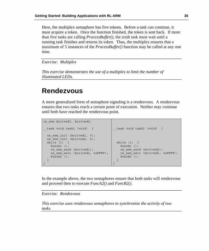
Rendezvous A more generalized form of semaphore signaling is a rendezvous. A rendezvous ensures that two tasks reach a certain point of execution. Neither may continue until both have reached the rendezvous point.
os_sem Arrived1, Arrived2; __task void task1 (void) { os_sem_init (Arrived1, 0); os_sem_init (Arrived2, 0); while (1) { FuncA1 (); os_sem_send (Arrived1); os_sem_wait (Arrived2, 0xFFFF); FuncA2 (); } }
__task void task2 (void) { while (1) { FuncB1 (); os_sem_send (Arrived2); os_sem_wait (Arrived1, 0xFFFF); FuncB2 (); } }
In the example above, the two semaphores ensure that both tasks will rendezvous and proceed then to execute FuncA2() and FuncB2().
Exercise: Rendezvous This exercise uses rendezvous semaphores to synchronize the activity of two tasks.
36 Chapter 2. Developing With an RTOS
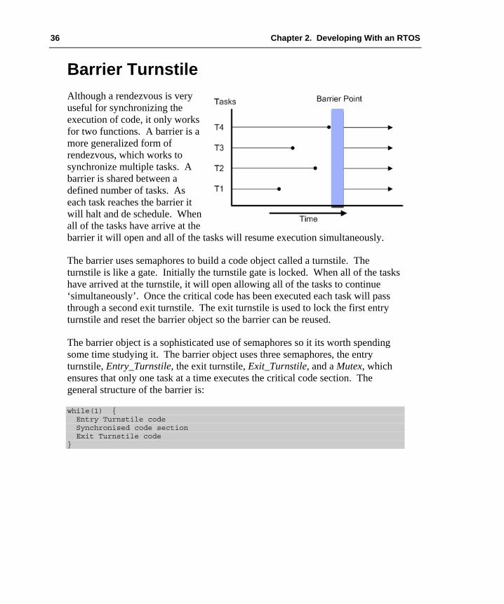
Barrier Turnstile Although a rendezvous is very useful for synchronizing the execution of code, it only works for two functions. A barrier is a more generalized form of rendezvous, which works to synchronize multiple tasks. A barrier is shared between a defined number of tasks. As each task reaches the barrier it will halt and de schedule. When all of the tasks have arrive at the barrier it will open and all of the tasks will resume execution simultaneously.
The barrier uses semaphores to build a code object called a turnstile. The turnstile is like a gate. Initially the turnstile gate is locked. When all of the tasks have arrived at the turnstile, it will open allowing all of the tasks to continue ‘simultaneously’. Once the critical code has been executed each task will pass through a second exit turnstile. The exit turnstile is used to lock the first entry turnstile and reset the barrier object so the barrier can be reused.
The barrier object is a sophisticated use of semaphores so it its worth spending some time studying it. The barrier object uses three semaphores, the entry turnstile, Entry_Turnstile, the exit turnstile, Exit_Turnstile, and a Mutex, which ensures that only one task at a time executes the critical code section. The general structure of the barrier is:
while(1) { Entry Turnstile code Synchronised code section Exit Turnstile code }

Getting Started: Building Applications with RL-ARM 37
The code for the entry turnstile is duplicated in each of the participating tasks:
os_sem_init(Mutex, 1); os_sem_init(Entry_Turnstile, 0); os_sem_init(Exit_Turnstile, 1); count = 0; …………… while (1) { …………… os_sem_wait (Mutex, 0xffff); // Begin critical section count = count+1; if (count==4) { os_sem_wait (Exit_Turnstile, 0xffff); os_sem_send (Entry_Turnstile); } os_sem_send (Mutex); // End critical section os_sem_wait (Entry_Turnstile, 0xffff); // Turnstile gate os_sem_send (Entry_Turnstile);
In this example, a barrier synchronizes four tasks. As the first task arrives, it will increment the count variable. Execution continues until it reaches the turnstile gate os_sem_wait(Entry_Turnstile,0xffff). At this point, the Entry_Turnstile semaphore is zero. This will cause the task to halt and de-schedule. The same will happen to the second and third task. When the fourth task enters the turnstile, the value of count will become four. This causes the if( count == 4) statement to be executed. Now, a token is placed into the Entry_Turnstile semaphore. When the fourth task reaches the os_sem_wait(Entry_Turnstile,0xffff) statement, a token is available, so it can continue execution. The turnstile gate is now open. Once the fourth task has passed through the gate, it places a token back into the Entry_Turnstile semaphore. This allows a waiting task to resume execution. As each waiting task resumes, it writes a token into the Entry_Turnstile semaphore. The Mutex semaphore locks access to the critical section of the turnstile. The Mutex semaphore ensures that each task will exclusively execute the critical section. In the critical section, the last arriving task will also remove a token from Exit_Turnstile. This closes the gate of the Exit_Turnstile, as we shall see below.
os_sem_wait (Mutex, 0xffff); // Begin critical section count = count-1; if (count==0) { os_sem_wait (Entry_Turnstile,0xffff); os_sem_send (Exit_Turnstile); } os_sem_send (Mutex); // End critical section os_sem_wait (Exit_Turnstile,0xffff); ); // Turnstile gate os_sem_send (Exit_Turnstile); }
38 Chapter 2. Developing With an RTOS
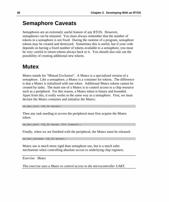
Semaphore Caveats Semaphores are an extremely useful feature of any RTOS. However, semaphores can be misused. You must always remember that the number of tokens in a semaphore is not fixed. During the runtime of a program, semaphore tokens may be created and destroyed. Sometimes this is useful, but if your code depends on having a fixed number of tokens available to a semaphore, you must be very careful to return tokens always back to it. You should also rule out the possibility of creating additional new tokens.
Mutex Mutex stands for “Mutual Exclusion”. A Mutex is a specialized version of a semaphore. Like a semaphore, a Mutex is a container for tokens. The difference is that a Mutex is initialized with one token. Additional Mutex tokens cannot be created by tasks. The main use of a Mutex is to control access to a chip resource such as a peripheral. For this reason, a Mutex token is binary and bounded. Apart from this, it really works in the same way as a semaphore. First, we must declare the Mutex container and initialize the Mutex:
os_mut_init (OS_ID mutex);
Then any task needing to access the peripheral must first acquire the Mutex token:
os_mut_wait (OS_ID mutex, U16 timeout);
Finally, when we are finished with the peripheral, the Mutex must be released:
os_mut_release (OS_ID mutex);
Mutex use is much more rigid than semaphore use, but is a much safer mechanism when controlling absolute access to underlying chip registers.
Exercise: Mutex This exercise uses a Mutex to control access to the microcontroller UART.

Getting Started: Building Applications with RL-ARM 39
Mutex Caveats Clearly, you must take care to return the Mutex token when you are finished with the chip resource, or you will have effectively prevented any other task from accessing it. You must also be careful about using the os_task_delete() call on functions that control a Mutex token. RTX is designed to be a small footprint RTOS. Consequently, there is no task deletion safety. This means that if you delete a task that is controlling a Mutex token, you will destroy the Mutex token and prevent any further access to the guarded peripheral.
Mailbox So far, all of the inter-task communication methods have only been used to trigger execution of tasks: they do not support the exchange of program data between tasks. Clearly, in a real program we will need to move data between tasks. This could be done by reading and writing to globally declared variables. In anything but a very simple program, trying to guarantee data integrity would be extremely difficult and prone to unforeseen errors. The exchange of data between tasks needs a more formal asynchronous method of communication.
RTX contains a mailbox system that buffers messages into mail slots and provides a FIFO queue between the sending and receiving tasks. The mailbox object supports transfer of single variable data such as byte, integer and word-width data, formatted fixed length messages, and variable length messages. We will start by having a look at configuring and using fixed length messaging. For this example, we are going to transfer a message consisting of a four-byte array that contains nominally ADC results data and a single integer of I/O port data.
unsigned char ADresult [4]; unsigned int PORT0;
To transfer this data between tasks, we need to declare a suitable data mailbox. A mailbox consists of a buffer formatted into a series of mail slots and an array of pointers to each mail slot.
A mailbox object consists of a memory block formatted into message buffers and a set of pointers to each buffer.

40 Chapter 2. Developing With an RTOS
To configure a mailbox object we must first declare the message pointers. Here we are using 16 mail slots. This is an arbitrary number and varies depending on your requirements, but 16 is a typical starting point. The message pointers are declared as an array of unsigned integers using the following macro:
os_mbx_declare (MsgBox, 16);
Next, we must declare a structure to hold the data to be transferred. This is the format of each message slot:
typedef struct { unsigned char ADresult [4]; unsigned int PORT0; } MESSAGE;
Once we have defined the format of the message slot, we must reserve a block of memory large enough to accommodate 16 message slots:
_declare_box (mpool, sizeof (MESSAGE), 16);
This block of memory then has to be formatted into the required 16 mail slots using a function provided with the RTOS:
_init_box (mpool, sizeof (mpool), sizeof (MESSAGE));
Now, if we want to send a message between tasks, we can create a pointer of the message structure type and allocate it to a mail slot.
MESSAGE *mptr; mptr = _allocbox (mpool);
Next, we fill this mail slot with the data to be transferred:
for (int i=0; i<4; i++) { mptr->ADresult [i] = ADresult (i); mptr->PORT0 = IOPIN0; }

Getting Started: Building Applications with RL-ARM 41
Then we send the message.
os_mbx_send (MsgBox, mptr, 0xffff);
In practice, this locks the mail slot protecting the data, and the message pointer is transferred to the waiting task. Further messages can be sent using the same calls, which will cause the next mail slot to be used. The messages will form a FIFO queue. In the receiving task, we must declare a receiving pointer with the message structure type. Then we wait for a message with the os_mxb_wait() call. This call allows us to nominate the mailbox that we want to use, provide the pointer to the mail slot buffer, and specify a timeout value.
MESSAGE *rptr;
When the message is received, we can simply access the data in the mail slot and transfer them to variables within the receiving task.
pwm_value = *rptr->ADresult [0];
Finally, when we have made use of the data within the mail slot it can be released so that it can be reused to transfer further messages.
_free_box (mpool, rptr);
The following code shows how to put all this together. First the initializing code that may be called before RTX is started.
typedef struct { unsigned char ADresult [4]; unsigned int PORT0; } MESSAGE; unsigned int mpool [16 * sizeof (MESSAGE) / 4 + 3]; _declare_box (mpool, sizeof (MESSAGE), 16); main() { … _init_box (mpool, sizeof (mpool), sizeof (MESSAGE)); os_sys_init (Send_Task); … }
42 Chapter 2. Developing With an RTOS
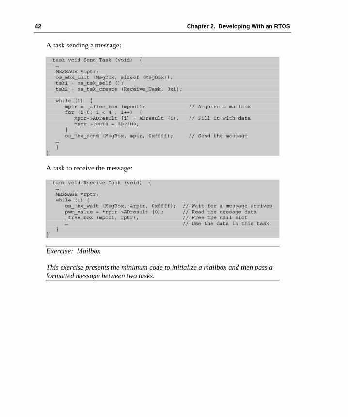
A task sending a message:
__task void Send_Task (void) { … MESSAGE *mptr; os_mbx_init (MsgBox, sizeof (MsgBox)); tsk1 = os_tsk_self (); tsk2 = os_tsk_create (Receive_Task, 0x1); while (1) { mptr = _alloc_box (mpool); // Acquire a mailbox for (i=0; i < 4 ; i++) { Mptr->ADresult [i] = ADresult (i); // Fill it with data Mptr->PORT0 = IOPIN0; } os_mbx_send (MsgBox, mptr, 0xffff); // Send the message … } }
A task to receive the message:
__task void Receive_Task (void) { … MESSAGE *rptr; while (1) { os_mbx_wait (MsgBox, &rptr, 0xffff); // Wait for a message arrives pwm_value = *rptr->ADresult [0]; // Read the message data _free_box (mpool, rptr); // Free the mail slot … // Use the data in this task } }
Exercise: Mailbox This exercise presents the minimum code to initialize a mailbox and then pass a formatted message between two tasks.

Getting Started: Building Applications with RL-ARM 43
Task Lock and Unlock In a real application, it is often necessary to ensure that a section of code runs as a contiguous block, so that no interrupts occur while it is executing. In an RTX-based application, this cannot be guaranteed, as the scheduler is continually interrupting each task. To ensure a continuous execution, you must use the task lock and task unlock system calls, which disable and re-enable the scheduler:
tsk_lock (); do_critical_section (); tsk_unlock ();
The critical section of code must be kept to a minimum, as a long period with the scheduler disabled will disrupt the operation of the RTOS. The source code for the tsk_lock() and tsk_unlock() functions on the OS_LOCK and OS_UNLOCK macros are located in the RTX_Config.c file and may be modified to meet any special requirements.
Configuration So far, we have looked at the RTX API. This includes task management functions, time management, and inter-task communication. Now that we have a clear idea of exactly what the RTX kernel is capable of, we can take a more detailed look at the configuration file. As mentioned at the beginning, you must select the correct RTX_Config.c for the microcontroller that you are using. All supported microcontrollers have a pre-configured configuration file, so RTX only needs minimal configuration.
Like the other configuration files, the RTX_Config.c file is a template file that presents all the necessary configurations as a set of menu options.
44 Chapter 2. Developing With an RTOS
Task Definitions In the Task Definitions section, we define the basic resources that will be required by the tasks. For each task, we allocate a default stack space (in the above example this is 200 bytes). We also define the maximum number of concurrently running tasks. Thus, the amount of RAM required for the above example can be calculated easily as 200 x 6 = 1,200 bytes. If some of our tasks need a larger stack space, they must be started with the os_task create_usr() API call. If we are defining custom stack sizes, we must define the number of tasks with custom stacks. Again, the RAM requirement can be calculated easily.
During development, RTX can be set up to trap stack overflows. When this option is enabled, an overflow of a task stack space will cause the RTX kernel to call the os_stk_overflow() function that is located in the RTX_Config.c file. This function gets the TASK ID of the running task and then sits in an infinite loop. The stack checking option is intended for use during debugging and should be disabled on the final application to minimize the kernel overhead. However, it is possible to modify the os_stack_overflow() function, if enhanced error protection is required in the final release.
The final option in the Task Definitions section allows you to define the number of user timers. It is a common mistake to leave this set at zero. If you do not set this value to match the number of virtual timers in use by your application, the os_timer() API calls will fail to work.
For Cortex-based microcontrollers the Task Definitions section has one additional option. Disabling the “run in privileged mode” tick box allows the RTOS kernel to run in Handler Mode with privileged access, while the user tasks run in Thread Mode with unprivileged access. This means that the RTX kernel has full access to the microcontroller resources and its own stack space while the application code has limited access to the microcontroller resources. For example, it cannot access the Cortex interrupt control registers. This can be very useful for safety critical code where we may need to partition the user task code from the kernel code.

Getting Started: Building Applications with RL-ARM 45
System Timer Configuration The system timer configuration section defines which on-chip timer will be used to generate a periodic interrupt to provide a time base for the scheduler. On ARM7 and ARM9-based microcontroller, you need to make use of a general-purpose timer available in the silicon. With a Cortex-based microcontroller, there is no need to select a timer, as the Cortex processor contains a dedicated SysTick timer, which is intended to be used by an RTOS. In both cases, we must next define the input frequency to the timer. For an ARM7 or ARM9-based microcontroller this will generally be the advanced peripheral bus frequency. For a Cortex-MX-based microcontroller it will generally be the CPU frequency. Next, we must define our timer tick rate. Timer interrupts are generated at this rate. On each timer tick, the RTOS kernel will check for RTOS features (scheduler, events, semaphores, etc) and then schedule the appropriate action. Thus, a high tick rate makes the RTOS more sensitive to events, at the expense of continually interrupting the executing task. The timer tick value will depend on your application, but the default starting value is set to 10ms.
Round Robin Task Switching The final configuration setting allows you to enable round robin scheduling and define the time slice period. This is a multiple of the timer tick rate, so in the above example, each task will run for five ticks or 50ms before it will pass execution to another task of the same priority that is ready to run. If no task of the same priority is ready to run, it will continue execution.
Scheduling Options RTX allows you to build an application with three different kernel-scheduling options. These are:
Pre-emptive scheduling, Round robin scheduling, and Co-operative multi-tasking.

46 Chapter 2. Developing With an RTOS
Pre-emptive Scheduling If the round robin option is disabled in the RTX_Config.c file, each task must be declared with a different priority. When the RTOS is started and the tasks are created, the task with the highest priority will run.
In a pre-emptive RTOS, each task has a different priority level and will run until it is pre-empted or has reached a blocking OS call.
This task will run until it blocks, i.e. it is forced to wait for an event flag, semaphore, or other object. When it blocks, the next ready task with the highest priority will be scheduled and will run until it blocks, or a higher priority task becomes ready to run. Therefore, with pre-emptive scheduling we build a hierarchy of task execution, with each task consuming variable amounts of run time.
Round Robin Scheduling A round-robin-based scheduling scheme can be created by enabling the round robin option in the RTX_Config.c file and declaring each task with the same priority.
In a round robin RTOS tasks will run for a fixed period, or time slice, or until they reach a blocking OS call.
In this scheme, each task will be allotted a fixed amount of run time before execution is passed to the next ready task. If a task blocks before its time slice has expired, execution will be passed to the next ready task.

Getting Started: Building Applications with RL-ARM 47
Round Robin Pre-emptive Scheduling As discussed at the beginning of this chapter, the default scheduling option for RTX is round robin pre-emptive. For most applications, this is the most useful option and you should use this scheduling scheme unless there is a strong reason to do otherwise.
Co-operative Multitasking A final scheduling option is co-operative multitasking. In this scheme, round robin scheduling is disabled and each task has the same priority. This means that the first task to run will run forever unless it blocks. Then execution will pass to the next ready task.
In a co-operative RTOS, each task will run until it reaches a blocking OS call or uses the os_tsk_pass() call.
Tasks can block on any of the standard OS objects, but there is also an additional system call, os_task_pass(), that schedules a task to the READY state and passes execution to the next ready task.
Priority Inversion Finally, no discussion of RTOS scheduling would be complete without mentioning priority inversion.
A priority inversion is a common RTOS design error. Here, a high priority task may become delayed or permanently blocked by a medium priority task.
In a pre-emptive scheduling system, it is possible for a high priority task T1 to block while it calls a low priority task T3 to perform a critical function before T1 continues.

48 Chapter 2. Developing With an RTOS
However, the low priority task T3 could be pre-empted by a medium priority task T2. Now, T2 is free to run until it blocks (assuming it does) before allowing T3 to resume completing its operation and allowing T1 to resume execution. The upshot is the high priority task T1 that is blocked and that becomes dependent on T2 to complete before it can resume execution.
os_tsk_prio (tsk3, 10); // raise the priority of task3 os_evt_set (0x0001, tsk3); // trigger it to run os_evt_wait_or (0x0001, 0xffff); // wait for Task3 to complete os_tsk_prio (tsk3, 1); // lower its priority
The answer to this problem is priority elevation. Before T1 calls T3 it must raise the priority of T3 to its level. Once T3 has completed, its priority can be lowered back to its initial state.
Exercise: Priority Inversion This exercise demonstrates a priority inversion and priority elevation.

Getting Started: Building Applications with RL-ARM 49
Chapter 3. RL-Flash Introduction This chapter discusses configuring and using the RL-Flash embedded file system. To many experienced developers of small embedded systems, the concept of using a file system may be considered something of a luxury. However, technology has moved on, and, as we saw in the first chapter, ARM processor-based microcontrollers now have the processing power to make using an RTOS practical. They also have the memory resources to support the use of embedded file systems. Adding a file system to a small-embedded system allows you to build applications that are far more complex.
The file system can be used to store program data during deep power saving modes, or for holding program constants, or even for storing firmware upgrades for a bootloader. In short, a file system is a new and extremely useful tool for developers of small, embedded systems.
The RL-Flash file system allows you to place a file system in most common memory types including SRAM, Parallel Flash, Serial Flash, and SD/MMC cards. In the case of SD/MMC cards, FAT12, FAT16, and FAT32 are supported. As we will see in later chapters, the file system can be accessed through the USB Mass Storage Class and through Ethernet with the Trivial File Transfer Protocol (TFTP). This provides an easy and well-understood method of accessing your data. Throughout this chapter, we will first discuss configuring a RAM-based file system that occupies the internal SRAM of a small microcontroller. Then we will use this file system to review the ANSI file I/O functions available within RL-Flash. In the remainder of the chapter, we will discuss configuring the file system for the remaining memory formats.
Getting Started In this first section, we will look at configuring the file system to use the internal RAM of a typical ARM processor-based microcontroller. Although this is not usually practical in real embedded systems, as all data would be lost once power is removed from the microcontroller, it does give us an easy starting point with which to practice our file handling skills.

50 Chapter 3. RL-Flash Introduction
Setting-Up the File System The RL-Flash file system can be used standalone or in conjunction with RTX. The file system library functions are re-entrant and thread safe. Therefore, with RTX, any task can access the file system. Note that, if the code is build with the MDK-ARM, MicroLIB is not supporting the stdlib functions used by the file system, and so you must use the default ARM Compiler libraries.
The RL-Flash file system can use on-chip or external SRAM. If an external SRAM is used, provide the initializing code to configure the external bus of the microcontroller. In the examples below, we configure the file system to use the internal RAM of a typical microcontroller.
The minimal configuration of the RL-FlashFS file system consists of its library and a configuration file. Set the project heap size to a minimum of 0x1000.
Our first file system project consists of the startup code and the Retarget.c library support file. Also, add the file system library FS_ARM_L.lib for ARM7/9-based devices and FS_CM3.lib for Cortex-M-based devices. The files are located in the library directory, such as C:\KEIL\ARM\RV31\LIB for the 3.1 compiler version, where as File_Config.c is located in C:\KEIL\ARM\RL\FLASHFS\SRC. Once these files are part of the project, create a module, main.c that contains the source code. All the necessary configuration is done in the startup code and the File_Config.c file.

Getting Started: Building Applications with RL-ARM 51
The file system buffers data in dynamically allocated memory, so we must reserve heap space in the startup code.
In File_Config.c, enable the drive type we want to use and set its parameters. If several drives are used, a default drive can also be defined. It is possible to enable the file system volumes and place them on different physical media, including internal/external parallel Flash memory, SPI EEPROM, internal or external parallel SRAM, and MultiMedia/SD memory cards. When configured, each drive has a default drive letter as shown in the table.
We will discuss each of these formats in turn, but for now we will define a file system in on-chip RAM. This is quick and simple to configure and can be debugged in both real target hardware via a ULINK® USB-JTAG Adapter and in simulation. Once the project has been defined and all of the modules have been added, we simply need to configure the base address of the file system in RAM, its size in memory and the number of sectors. The file system may be located in any valid region of RAM and has a minimum size of 16K. The number of sectors that you have depends on how you intend to use the file system. If you intend to have a small number of large files, then select a small sector number. If, on the other hand, you expect to create a large number of small files, then select a large number of sectors. You can select between 8, 16, 32, 64, and 128 sectors per volume drive. Once configured, we can add the necessary code to initialize the volume for use within our application code.
if (fcheck ("R:") != 0) { // check for a formatted drive if (fformat ("R:") != 0) { // format the drive … // error handling code } }
The fcheck() function can be used to determine if there is a valid formatted volume present. The fformat() function can be used at any time to format/reformat the drive. After formatting all the drive memory contents will be set to 0x00.
Exercise: First File System This first file system project guides you through setting up a RAM-based file system. This can run on real hardware or within the µVision Simulator.

52 Chapter 3. RL-Flash Introduction
File I/O Routines Once the file system has been configured, we can manipulate files.
Function Description
fopen Creates a new file or opens an existing file. fclose Writes buffered data to a file and then closes the file. fflush Writes buffered data to a file.
To create a file, open a file on the volume and define a handler to it. This handler, with which we can read and write to the file, is a pointer to the open file.
#include <stdio.h> FILE *Fptr;
Include the stdio.h library to define our file handler as type FILE. Next, create a file and check that it has opened. fopen() requires a string for the file name and an access attribute, which can be “w” write, “a” append, or “r” read.
Fptr = fopen ("Test.txt","w");
If the file cannot be created or opened, a NULL pointer is returned.
if (Fptr == NULL) { …; // error handler }
Once you have finished using the file, you must close it by calling fclose(). Up to this point, all data written to the file is buffered in the heap space. When you close the file, the data is written to the physical storage media. Consider this carefully if you have multiple file streams or are storing large streams of data.
fclose (Fptr);
Once we have created a file, a number of functions help us work with it.
Function Description
feof Reports whether the end of the file stream has been reached. ferror Reports whether there is an error in the file steam. fseek Moves the file stream in pointer to a new location. ftell Gets the current location of the file pointer. rewind Moves the file stream in file pointer to the beginning of the file.

Getting Started: Building Applications with RL-ARM 53
feof() returns zero until the end of file is reached. Notice, it is possible to read past the end of a file. While reading or writing data, ferror() reports access errors in the file stream. Once an error has occurred, ferror() returns the error code until the file is closed, or until the file pointer is rewound to the start of the file. fseek(), ftell(), and rewind() position the file pointer within the file. fseek() moves the file pointer to a location within a file. This location is defined relative to an origin, which can be the start or the end of the file, or the current file pointer position. ftell() reports the current location of the file pointer relative to the beginning of the file. rewind() places the file pointer at the start of the file.
rewind (Fptr); // Place file-pointer at the start of file fseek (Fptr, 4, SEEK_CUR); // Move 4 chars forward rel. to the FP location location = ftell (Fptr); // Read the file pointer location
Four standard functions exist to write data to a file stream in byte, character, string, or formatted output format. Similarly, four analogous functions exist to read data.
Function Description
fwrite Writes a number of bytes to the file stream. fputc Writes a character to the file stream. fputs Writes a string to the file stream. fprintsf Writes a formatted string to the file stream. fread Reads a number of bytes from the file stream. fgetc Reads a character from the file stream. fgets Reads a string from the file stream. fscanf Reads a formatted string from the file stream.
while (!feof (Fptr)) { byte = fgetc (Fptr); if (ferror (Fptr)) { …; // Error handling } }
Exercise: File Handling This project contains several examples, which demonstrate creating files, reading and writing data, and managing the data within a file.

54 Chapter 3. RL-Flash Introduction
Volume Maintenance Routines As you create and update files, it is important to maintain the health of the drive. A number of functions maintain the volume and manipulate the content of the drive. The file system provides five drive and three file maintenance functions.
Function Description
fformat Formats the drive. fcheck Checks the consistency of the drive. ffree Reports the free space available in the drive. fanalyse Checks the drive for fragmentation. fdefrag Defragments the drive.
We have already used the fcheck() and fformat() functions. The additional drive maintenance functions include ffree() that will report the available free disk space and fanalyse() that can be used to check the fragmentation level of a selected drive. This function returns a value 0 – 255 to indicate the current level of drive fragmentation. Once a drive becomes too fragmented, the fdefrag() function may be used to reorganize the volume memory and maximize the available space.
if (ffree ("R:") < THRESHOLD) { // When free space reaches a minimum if (fanalyse ("R:") > 100) { // Check the fragmentation fdefrag ("R:"); // If necessary defrag the drive } }
Function Description
fdelete Deletes a selected file. frename Renames a selected file. ffind Locates files by name or extension.
Three functions are also provided to allow you to manage the files stored within the drive volume. The functions frename() and fdelete() allow you to rename and delete a selected file within a chosen drive.
frename ("R:Test1.txt", "New_Test.txt"); // Rename file fdelete ("R:Test2.txt"); // Delete file
You can also search the contents of the drive with the ffind() function. This will find files that match a specified pattern. When a file is found, its details are reported in a structure called info.
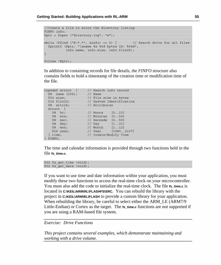
Getting Started: Building Applications with RL-ARM 55
//Create a file to store the directory listing FINFO info; Fptr = fopen ("directory.log", "w"); while (ffind ("R:*.*", &info) == 0) { // Search drive for all files fprintf (Fptr, "\nname %s %5d bytes ID: %04d", info.name, info.size, info.fileID); } fclose (Fptr);
In addition to containing records for file details, the FINFO structure also contains fields to hold a timestamp of the creation time or modification time of the file.
typedef struct { // Search info record S8 name [256]; // Name U32 size; // File size in bytes U16 fileID; // System Identification U8 attrib; // Attributes struct { U8 hr; // Hours [0..23] U8 min; // Minutes [0..59] U8 sec; // Seconds [0..59] U8 day; // Day [1..31] U8 mon; // Month [1..12] U16 year; // Year [1980..2107] } time; // Create/Modify Time } FINFO;
The time and calendar information is provided through two functions held in the file fs_time.c.
U32 fs_get_time (void); U32 fs_get_date (void);
If you want to use time and date information within your application, you must modify these two functions to access the real-time clock on your microcontroller. You must also add the code to initialize the real-time clock. The file fs_time.c is located in C:\KEIL\ARM\RL\FLASHFS\SRC. You can rebuild the library with the project in C:\KEIL\ARM\RL\FLASH to provide a custom library for your application. When rebuilding the library, be careful to select either the ARM_LE (ARM7/9 Little-Endian) or Cortex as the target. The fs_time.c functions are not supported if you are using a RAM-based file system.
Exercise: Drive Functions This project contains several examples, which demonstrate maintaining and working with a drive volume.

56 Chapter 3. RL-Flash Introduction
Flash Drive Configuration Although a RAM-based file system can be battery-backed, or can be used to store temporary files during the run time of an application, we usually think of a file system as having non-volatile storage. To this end, we can configure the file system to use the internal Flash memory of a microcontroller, or external parallel Flash, which is memory-mapped onto the microcontroller’s external bus.
First, modify the File_Config.c file. This time select the Flash drive as the target drive. Once selected, we must define the start. Next, configure the target base address and drive size. This should map onto the Flash sectors of the microcontroller’s memory. Next, we must add the programming algorithms for the internal Flash memory. These algorithms are defined for supported microcontrollers and are located in C:\KEIL\ARM\RL\FLASHFS\FLASH.
Each subdirectory contains the necessary support files for a given microcontroller or parallel Flash device. Each of these directories contains FS_FlashDev.h and FS_FlashPrg.c. Copy these files to your project directory and add FS_FlashPrg.c to your project. If there is no direct support for your particular microcontroller, do not be concerned; we will look at developing Flash drivers next.
To use parallel Flash as a file system we must add two new files:
1. The FS_Flash.h include file that contains a mapping of the physical Flash sectors.
2. The Flash_page.c file that contains the low level Flash write and erase routines.
The file FS_FlashPrg.c provides the necessary Flash programming algorithm and FS_FlashDev.h provides the mapping to the physical Flash sectors. The FlashDev.h file maps all of the available Flash sectors to the file system by default. We must modify this file to map only the sectors that are actually being used by our file system.

Getting Started: Building Applications with RL-ARM 57
// Flash sector definitions in Flash_Page.c // #define FLASH_DEVICE \ DFB (0x008000, 0x000000), \ /* Sector size, Start address */ DFB (0x008000, 0x008000), \ /* Sector size, Start address */ #define FL_NSECT 2
// File_Config.c as displayed as in the µVision Configuration Wizard // Traget device Base address 0x0000 8000 Device Size in bytes 0x0001 0000
Each physical Flash sector used by the file system must be included in the FLASH_DEVICE definition. Each sector definition includes the size of the sector and its address as an offset from the target device base address that is set in file config.h. In the example above we are defining a file system located at the 32KB boundary of size 64KB. In the physical Flash memory on the microcontroller, this occupies two Flash sectors each of 32KB. Finally, we must set the FL_NSECT define to the number of physical Flash sectors used by the file system in this case two.
Once you have added these files to your project and made the necessary configuration changes, the Flash file system is ready to use. The function calls that we used for the RAM-based system work in exactly the same way for the Flash-based system. Before using the Flash-based file system, the application code must call finit() before performing any other file system operations.
void main (void) { finit (); ... }
Exercise: Flash File System This exercise demonstrates how to locate a file system in the internal Flash memory of an ARM processor-based microcontroller.

58 Chapter 3. RL-Flash Introduction
Adapting Flash Algorithms for RL-Flash If RL-Flash does not provide direct support for your microcontroller or the parallel Flash on your board, it is possible to adapt the programming algorithms, used by the Keil ULINK USB-JTAG adapter family, to use them as drivers for the Flash file system. The ULINK family Flash programming algorithms are located in C:\KEIL\ARM\FLASH.
For each microcontroller, the ULINK programming algorithms are included in two files: FlashPrg.c and FlashDev.c. Copy these files to a new directory and rename FlashPrg.c to FS_FlashPrg.c.
This file contains the basic low-level programming algorithm required by the file system. To make the programming algorithms compatible with the file system you must make the following changes. First, change the include file name from:
#include "..\FlashOS.H" to #include <File_Config.h>.
Next, rename the following functions:
from int Init (unsigned long adr, unsigned long clk, unsigned long fnc) to int fs_Init (U32 adr, U32clk),
from int EraseSector (unsigned long adr) to int fs_EraseSector (U32 adr),
and int ProgramPage (unsigned long adr, unsigned long sz, unsigned char *buf) to int fs_ProgramPage (U32 adr, U32 sz, U8 *buf).
Finally, delete the functions UnInit() and EraseChip().
Depending on the underlying Flash technology, you may need to modify the program page function. This will depend on the write granularity of the Flash memory. Generally, you can use the program page function without modification if the Flash memory can be written with a word at a time. However, you will need to add the packed attribute to the data buffer to allow for unaligned buffer access. Change
M16 (adr) = *((unsigned short *) buf); to M16 (adr) = *((__packed unsigned short *) buf);
If the write granularity of the Flash memory is larger than a word, i.e. the Flash memory has a minimum write page size of 128 bytes, it will be necessary to
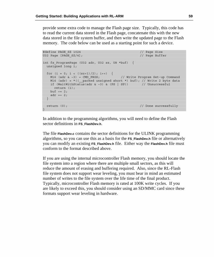
Getting Started: Building Applications with RL-ARM 59
provide some extra code to manage the Flash page size. Typically, this code has to read the current data stored in the Flash page, concatenate this with the new data stored in the file system buffer, and then write the updated page to the Flash memory. The code below can be used as a starting point for such a device.
#define PAGE_SZ 1024 // Page Size U32 Page [PAGE_SZ/4]; // Page Buffer int fs_ProgramPage (U32 adr, U32 sz, U8 *buf) { unsigned long i; for (i = 0; i < ((sz+1)/2); i++) { M16 (adr & ~3) = CMD_PRGS; // Write Program Set-up Command M16 (adr) = *((__packed unsigned short *) buf); // Write 2 byte data if (WaitWithStatus(adr & ~3) & (PS | SP)) // Unsuccessful return (1); buf += 2; adr += 2; } return (0); // Done successfully }
In addition to the programming algorithms, you will need to define the Flash sector definitions in FS_FlashDev.h.
The file FlashDev.c contains the sector definitions for the ULINK programming algorithms, so you can use this as a basis for the FS_FlashDev.h file or alternatively you can modify an existing FS_FlashDev.h file. Either way the FlashDev.h file must conform to the format described above.
If you are using the internal microcontroller Flash memory, you should locate the file system into a region where there are multiple small sectors, as this will reduce the amount of erasing and buffering required. Also, since the RL-Flash file system does not support wear leveling, you must bear in mind an estimated number of writes to the file system over the life time of the final product. Typically, microcontroller Flash memory is rated at 100K write cycles. If you are likely to exceed this, you should consider using an SD/MMC card since these formats support wear leveling in hardware.
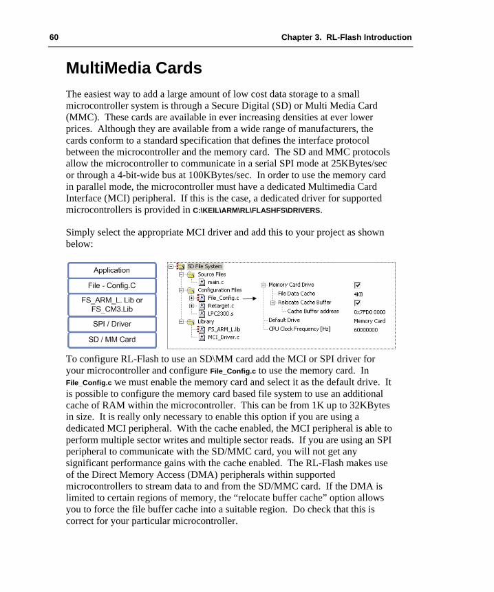
60 Chapter 3. RL-Flash Introduction
MultiMedia Cards The easiest way to add a large amount of low cost data storage to a small microcontroller system is through a Secure Digital (SD) or Multi Media Card (MMC). These cards are available in ever increasing densities at ever lower prices. Although they are available from a wide range of manufacturers, the cards conform to a standard specification that defines the interface protocol between the microcontroller and the memory card. The SD and MMC protocols allow the microcontroller to communicate in a serial SPI mode at 25KBytes/sec or through a 4-bit-wide bus at 100KBytes/sec. In order to use the memory card in parallel mode, the microcontroller must have a dedicated Multimedia Card Interface (MCI) peripheral. If this is the case, a dedicated driver for supported microcontrollers is provided in C:\KEIL\ARM\RL\FLASHFS\DRIVERS.
Simply select the appropriate MCI driver and add this to your project as shown below:
To configure RL-Flash to use an SD\MM card add the MCI or SPI driver for your microcontroller and configure File_Config.c to use the memory card. In File_Config.c we must enable the memory card and select it as the default drive. It is possible to configure the memory card based file system to use an additional cache of RAM within the microcontroller. This can be from 1K up to 32KBytes in size. It is really only necessary to enable this option if you are using a dedicated MCI peripheral. With the cache enabled, the MCI peripheral is able to perform multiple sector writes and multiple sector reads. If you are using an SPI peripheral to communicate with the SD/MMC card, you will not get any significant performance gains with the cache enabled. The RL-Flash makes use of the Direct Memory Access (DMA) peripherals within supported microcontrollers to stream data to and from the SD/MMC card. If the DMA is limited to certain regions of memory, the “relocate buffer cache” option allows you to force the file buffer cache into a suitable region. Do check that this is correct for your particular microcontroller.

Getting Started: Building Applications with RL-ARM 61
From this point onwards, the file system API can be used as normal. However, as we are communicating with an external memory card, which may have some timing latencies, it may fail the finit() call. To ensure that the file system always initializes correctly, it is advisable to allow for retries as shown below.
count = 3; while (finit() != 0) { if (!(count--)) { errorflag = 1; break; } }
By default, the file system uses the FAT16 file format. It is possible to enable FAT32 support for SD/MMC-based file systems. A memory card can be formatted with a FAT32 file system as follows:
fformat ("M:SD_CARD / FAT32");
A full erase of the card can also be performed during a format as follows:
fformat ("M:SD_CARD / WIPE");
If your microcontroller does not have a dedicated MCI peripheral, then it is possible to configure the file system library to communicate with the memory card in SPI mode. SPI driver files are provided in the same file system drivers’ directory. You simply need to add the SPI driver in place of the MCI driver, in order to configure your microcontroller to access the memory card in SPI mode.
Exercise: MMC-Based File System This project demonstrates configuration of a memory-card-based file system, using either a dedicated MCI peripheral or SPI interface.
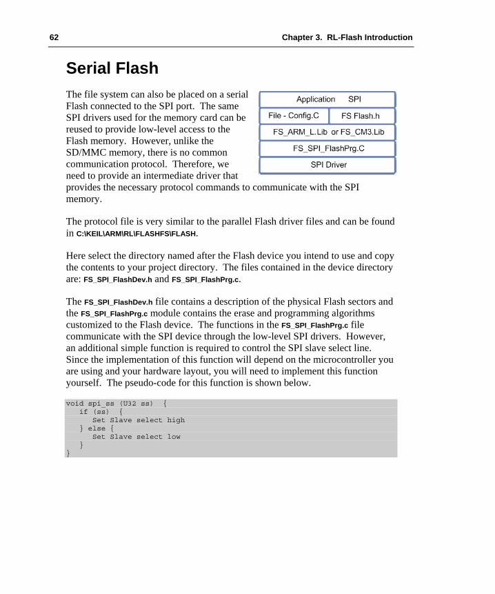
62 Chapter 3. RL-Flash Introduction
Serial Flash The file system can also be placed on a serial Flash connected to the SPI port. The same SPI drivers used for the memory card can be reused to provide low-level access to the Flash memory. However, unlike the SD/MMC memory, there is no common communication protocol. Therefore, we need to provide an intermediate driver that provides the necessary protocol commands to communicate with the SPI memory.
The protocol file is very similar to the parallel Flash driver files and can be found in C:\KEIL\ARM\RL\FLASHFS\FLASH.
Here select the directory named after the Flash device you intend to use and copy the contents to your project directory. The files contained in the device directory are: FS_SPI_FlashDev.h and FS_SPI_FlashPrg.c.
The FS_SPI_FlashDev.h file contains a description of the physical Flash sectors and the FS_SPI_FlashPrg.c module contains the erase and programming algorithms customized to the Flash device. The functions in the FS_SPI_FlashPrg.c file communicate with the SPI device through the low-level SPI drivers. However, an additional simple function is required to control the SPI slave select line. Since the implementation of this function will depend on the microcontroller you are using and your hardware layout, you will need to implement this function yourself. The pseudo-code for this function is shown below.
void spi_ss (U32 ss) { if (ss) { Set Slave select high } else { Set Slave select low } }
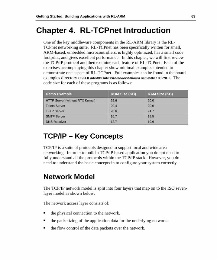
Getting Started: Building Applications with RL-ARM 63
Chapter 4. RL-TCPnet Introduction One of the key middleware components in the RL-ARM library is the RL-TCPnet networking suite. RL-TCPnet has been specifically written for small, ARM-based, embedded microcontrollers, is highly optimized, has a small code footprint, and gives excellent performance. In this chapter, we will first review the TCP/IP protocol and then examine each feature of RL-TCPnet. Each of the exercises accompanying this chapter show minimal examples intended to demonstrate one aspect of RL-TCPnet. Full examples can be found in the board examples directory C:\KEIL\ARM\BOARDS\<vendor>\<board name>\RL\TCPNET. The code size for each of these programs is as follows:
Demo Example ROM Size (KB) RAM Size (KB)
HTTP Server (without RTX Kernel) 25.6 20.0 Telnet Server 20.4 20.0 TFTP Server 20.6 24.7 SMTP Server 16.7 19.5 DNS Resolver 12.7 19.6
TCP/IP – Key Concepts TCP/IP is a suite of protocols designed to support local and wide area networking. In order to build a TCP/IP based application you do not need to fully understand all the protocols within the TCP/IP stack. However, you do need to understand the basic concepts in to configure your system correctly.
Network Model The TCP/IP network model is split into four layers that map on to the ISO seven-layer model as shown below.
The network access layer consists of:
the physical connection to the network. the packetizing of the application data for the underlying network. the flow control of the data packets over the network.

64 Chapter 4. RL-TCPnet Introduction
In a typical microcontroller-based system, this layer corresponds to the Ethernet MAC with PHY chip and the low-level device driver. The TCP/IP stack handles the transport and network routing layers.
The network layer handles the transmission of data packets between network stations using the Internet Protocol (IP). The transport layer provides the connection between application layers of different stations. Two protocols; the Transmission Control Protocol (TCP) and the User Datagram Protocol (UDP) handle this. The application layer provides access to the communication environment from your user application. This access is in the form of well-defined application layer protocols such as Telnet, SMTP, and HTTP. It is possible to define your own application protocol and communicate between nodes using custom TCP and UDP packets.
The main three protocols used to transfer application data are: the Internet Protocol (IP), the Transmission Control Protocol (TCP), and the User Datagram Protocol (UDP). A typical application will also require the Address Routing Protocol (ARP) and Internet Control Message Protocol (ICMP). In order to reduce the size of a TCP/IP implementation for a small microcontroller, some embedded stacks only implement a subset of the TCP/IP protocols. Such stacks assume that communication will be between a fully implemented stack, i.e. a PC and the embedded node. The RL-TCPnet is a full implementation that allows the embedded microcontroller to operate as a fully functional internet station.
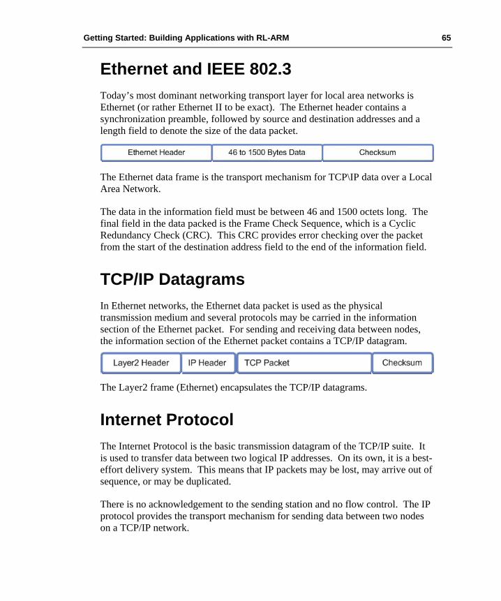
Getting Started: Building Applications with RL-ARM 65
Ethernet and IEEE 802.3 Today’s most dominant networking transport layer for local area networks is Ethernet (or rather Ethernet II to be exact). The Ethernet header contains a synchronization preamble, followed by source and destination addresses and a length field to denote the size of the data packet.
The Ethernet data frame is the transport mechanism for TCP\IP data over a Local Area Network.
The data in the information field must be between 46 and 1500 octets long. The final field in the data packed is the Frame Check Sequence, which is a Cyclic Redundancy Check (CRC). This CRC provides error checking over the packet from the start of the destination address field to the end of the information field.
TCP/IP Datagrams In Ethernet networks, the Ethernet data packet is used as the physical transmission medium and several protocols may be carried in the information section of the Ethernet packet. For sending and receiving data between nodes, the information section of the Ethernet packet contains a TCP/IP datagram.
The Layer2 frame (Ethernet) encapsulates the TCP/IP datagrams.
Internet Protocol The Internet Protocol is the basic transmission datagram of the TCP/IP suite. It is used to transfer data between two logical IP addresses. On its own, it is a best-effort delivery system. This means that IP packets may be lost, may arrive out of sequence, or may be duplicated.
There is no acknowledgement to the sending station and no flow control. The IP protocol provides the transport mechanism for sending data between two nodes on a TCP/IP network.
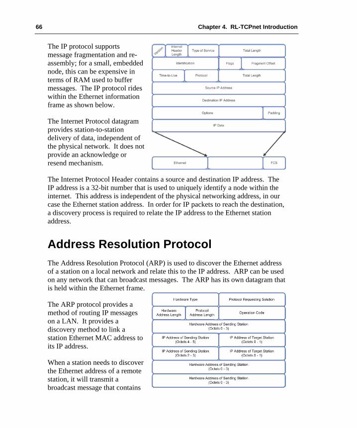
66 Chapter 4. RL-TCPnet Introduction
The IP protocol supports message fragmentation and re-assembly; for a small, embedded node, this can be expensive in terms of RAM used to buffer messages. The IP protocol rides within the Ethernet information frame as shown below.
The Internet Protocol datagram provides station-to-station delivery of data, independent of the physical network. It does not provide an acknowledge or resend mechanism.
The Internet Protocol Header contains a source and destination IP address. The IP address is a 32-bit number that is used to uniquely identify a node within the internet. This address is independent of the physical networking address, in our case the Ethernet station address. In order for IP packets to reach the destination, a discovery process is required to relate the IP address to the Ethernet station address.
Address Resolution Protocol The Address Resolution Protocol (ARP) is used to discover the Ethernet address of a station on a local network and relate this to the IP address. ARP can be used on any network that can broadcast messages. The ARP has its own datagram that is held within the Ethernet frame.
The ARP protocol provides a method of routing IP messages on a LAN. It provides a discovery method to link a station Ethernet MAC address to its IP address.
When a station needs to discover the Ethernet address of a remote station, it will transmit a broadcast message that contains

Getting Started: Building Applications with RL-ARM 67
the IP address of the remote station. The broadcast message also contains the local station’s Ethernet address and its IP address. All the other nodes on the network will receive the ARP broadcast message and can cache the sending node’s IP and station address for future use. All of the receiving stations will examine the destination IP address in the ARP datagram and the station with the matching IP address will reply back with a second ARP datagram containing its IP address and Ethernet station address.
This information is cached by the sending node (and possibly all the other nodes on the network). Now, when a node on the LAN wishes to communicate to the discovered station, it knows which Ethernet station address to use to route the IP packet to the correct node. If the destination node is not on the local network, the IP datagram will be sent to the default network gateway address where it will be routed through the wide area network.
Subnet Mask A local area network is a defined subnet of a network. Often it uses a specific IP address range that is defined for use as a private network (for example 192.168.0.xxx). The subnet mask defines the portion of the address used to select stations within the local network.
The subnet mask is used to define the station address range for the local area network.
The subnet mask defines the network address bits that form the identity of the local network. The remaining IP address bits can be used to assign the address of nodes on the local network. By using the subnet mask to determine the identity of the local network, any IP datagrams not destined for the local network are forwarded through the network gateway and then routed through the wider internet. Within a LAN, each network station must have the same subnet mask and a unique IP address. These settings may be configured manually on each station. It is possible to configure the subnet and IP address automatically using a dedicated protocol.

68 Chapter 4. RL-TCPnet Introduction
Dynamic Host Control Protocol DHCP The DHCP supports automatic allocation of IP addresses and configuration of the subnet mask within a LAN. A DHCP server must be present within the LAN. This can run on any station and listens on port 67. When a new station is added to the network, it will request its network configuration from the DHCP server before it becomes an active station within the network. The DHCP request process consists of four stages: discovery, offer, request, and acknowledgement.
An Ethernet station can be assigned automatically an IP address by a DHCP server. This process consists of four stages, discovery, offer, request, and acknowledge.
To discover the DHCP server, the new station sends a UDP broadcast packet with address 255.255.255.255. When the DHCP receives the DHCP discovery packet, it will reply back to the new station using the Ethernet MAC address contained within the discovery broadcast. In this packet, the DHCP server offers the new station an IP address. To accept this IP address the new station replies back with a second broadcast packet. The DHCP server will send a final acknowledgment packet that contains the remaining network configuration information and the lease duration of the IP address.
Internet Control Message Protocol The Internet Control Message Protocol (ICMP) is mainly used to report errors such as an unreachable destination or an unavailable service within a TCP/IP network. ICMP is the protocol used by the PING function that is used to check if a node exists on a network. The Internet Control Message Protocol must be implemented in a TCP/IP stack. However, in most embedded stacks only the PING Echo reply is implemented.
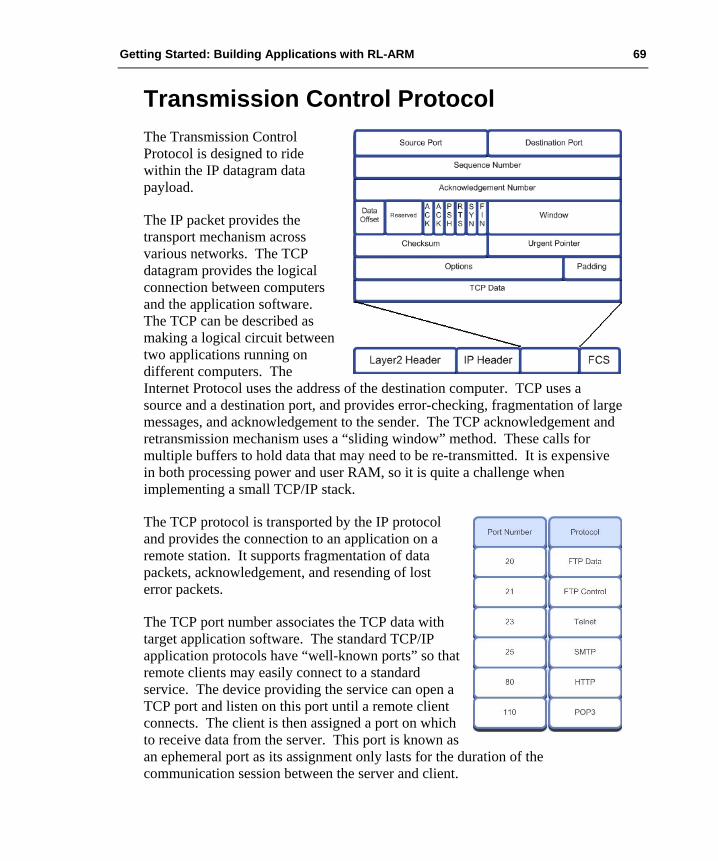
Getting Started: Building Applications with RL-ARM 69
Transmission Control Protocol The Transmission Control Protocol is designed to ride within the IP datagram data payload.
The IP packet provides the transport mechanism across various networks. The TCP datagram provides the logical connection between computers and the application software. The TCP can be described as making a logical circuit between two applications running on different computers. The Internet Protocol uses the address of the destination computer. TCP uses a source and a destination port, and provides error-checking, fragmentation of large messages, and acknowledgement to the sender. The TCP acknowledgement and retransmission mechanism uses a “sliding window” method. These calls for multiple buffers to hold data that may need to be re-transmitted. It is expensive in both processing power and user RAM, so it is quite a challenge when implementing a small TCP/IP stack.
The TCP protocol is transported by the IP protocol and provides the connection to an application on a remote station. It supports fragmentation of data packets, acknowledgement, and resending of lost error packets.
The TCP port number associates the TCP data with target application software. The standard TCP/IP application protocols have “well-known ports” so that remote clients may easily connect to a standard service. The device providing the service can open a TCP port and listen on this port until a remote client connects. The client is then assigned a port on which to receive data from the server. This port is known as an ephemeral port as its assignment only lasts for the duration of the communication session between the server and client.

70 Chapter 4. RL-TCPnet Introduction
User Datagram Protocol Like the Transmission Control Protocol, the User Datagram Protocol rides within the data packet of the Internet Protocol. Unlike TCP, UDP provides no acknowledgement and no flow control mechanisms. UDP can be defined as a best effort, connectionless protocol and is intended to provide a means of transferring data between application processes with minimal overhead. It provides no extra reliability over the Internet Protocol.
Like the Transmission Control Protocol, the User Datagram Protocol is transported by the Internet Protocol. Unlike TCP, UDP is a simple, low overhead protocol that provides an easy method of communication to a remote application.
Although delivery of data cannot be guaranteed with UDP, its simplicity and ease of use make it the basis of many important application protocols such as Domain Name Server (DNS) resolving and Trivial File Transfer Protocol (TFTP).
Sockets A socket is the combination of an IP address and a port number. In RL-TCPnet, support is provided for the most useful TCP/IP-based applications such as web server, using the Hypertext Transfer Protocol (HTTP) and e-mail, which is implemented with the Simple Mail Transfer Protocol (SMTP). This means that you do not need to control individual connections. However, if you do wish to generate your own custom TCP or UDP frames, a low-level sockets library is also provided. If you intend designing your own protocol you will need to decide between UDP or TCP frames. UDP is a lightweight protocol that allows you to send single frames. It does not provide any kind of acknowledgement from the remote station. If you want to implement a simple control protocol that will manage its own send and receive packets then use UDP. TCP is a more complicated protocol that provides a logical connection between stations. This includes acknowledgement and retransmission of messages, fragmentation of data over multiple packets and ordering of received packets. If you need to send large amounts of data between stations or need guaranteed delivery then use TCP.
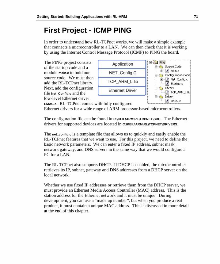
Getting Started: Building Applications with RL-ARM 71
First Project - ICMP PING In order to understand how RL-TCPnet works, we will make a simple example that connects a microcontroller to a LAN. We can then check that it is working by using the Internet Control Message Protocol (ICMP) to PING the board.
The PING project consists of the startup code and a module main.c to hold our source code. We must then add the RL-TCPnet library. Next, add the configuration file Net_Config.c and the low-level Ethernet driver EMAC.c. RL-TCPnet comes with fully configured Ethernet drivers for a wide range of ARM processor-based microcontrollers.
The configuration file can be found in C:\KEIL\ARM\RL\TCPNET\SRC. The Ethernet drivers for supported devices are located in C:\KEIL\ARM\RL\TCPNET\DRIVERS.
The net_config.c is a template file that allows us to quickly and easily enable the RL-TCPnet features that we want to use. For this project, we need to define the basic network parameters. We can enter a fixed IP address, subnet mask, network gateway, and DNS servers in the same way that we would configure a PC for a LAN.
The RL-TCPnet also supports DHCP. If DHCP is enabled, the microcontroller retrieves its IP, subnet, gateway and DNS addresses from a DHCP server on the local network.
Whether we use fixed IP addresses or retrieve them from the DHCP server, we must provide an Ethernet Media Access Controller (MAC) address. This is the station address for the Ethernet network and it must be unique. During development, you can use a “made up number”, but when you produce a real product, it must contain a unique MAC address. This is discussed in more detail at the end of this chapter.

72 Chapter 4. RL-TCPnet Introduction
RL-TCPnet also supports the NetBIOS Frames Protocol. If this is enabled, we can provide our node with a NetBIOS local host name as well as an IP address.
Finally, we must enable the TCP and UDP protocols. The ICMP just uses UDP, but as we will be using other application protocols that do use TCP, we will enable both here.

Getting Started: Building Applications with RL-ARM 73
Once the RL-TCPnet library has been configured, we need to add the following code to our application code.
void timer_poll () { if (100mstimeout) { timer_tick (); // RL-TCPnet function tick = __TRUE; } }
int main (void) { timer_init (); init_TcpNet (); while (1) { timer_poll (); main_TcpNet (); } }
The main while loop must be a non-blocking loop that makes a call to the RL-TCPnet library on each pass. In addition, we must provide a timer tick to the RL-TCPnet library. This must use a hardware timer to provide a periodic timeout tick. The tick period should be around 100ms. If you need a different tick rate, you should reconfigure the timer and change the timer tick interval in Net_Config.c.
Once configured, the project can be built and downloaded into the microcontroller so that we can test it on a real LAN.
Exercise: PING Project This project demonstrates how to configure the RL-TCPnet library to create a minimal TCP/IP station.
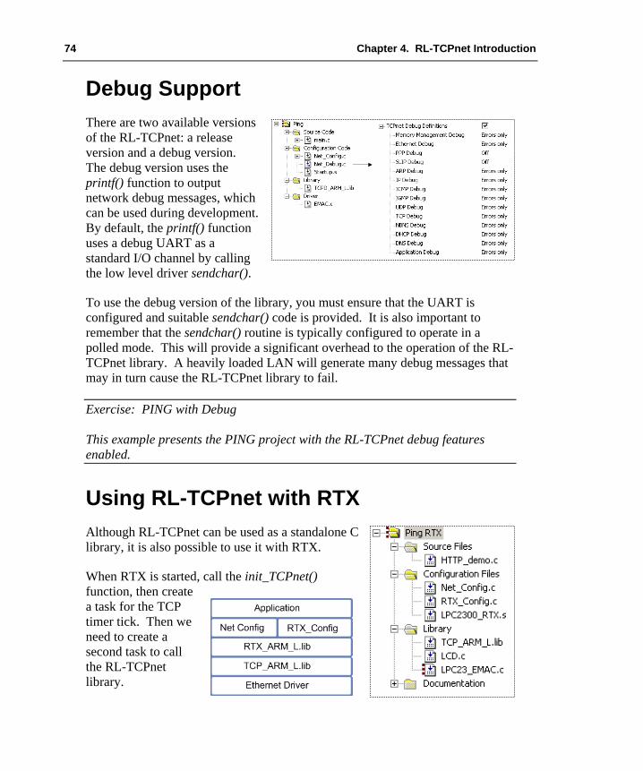
74 Chapter 4. RL-TCPnet Introduction
Debug Support There are two available versions of the RL-TCPnet: a release version and a debug version. The debug version uses the printf() function to output network debug messages, which can be used during development. By default, the printf() function uses a debug UART as a standard I/O channel by calling the low level driver sendchar().
To use the debug version of the library, you must ensure that the UART is configured and suitable sendchar() code is provided. It is also important to remember that the sendchar() routine is typically configured to operate in a polled mode. This will provide a significant overhead to the operation of the RL-TCPnet library. A heavily loaded LAN will generate many debug messages that may in turn cause the RL-TCPnet library to fail.
Exercise: PING with Debug This example presents the PING project with the RL-TCPnet debug features enabled.
Using RL-TCPnet with RTX Although RL-TCPnet can be used as a standalone C library, it is also possible to use it with RTX.
When RTX is started, call the init_TCPnet() function, then create a task for the TCP timer tick. Then we need to create a second task to call the RL-TCPnet library.
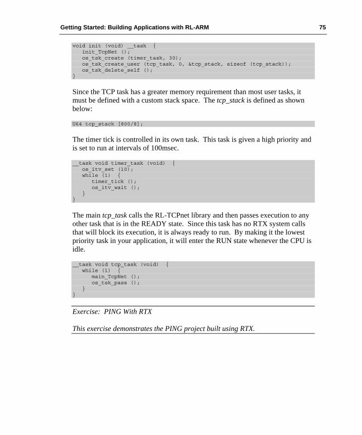
Getting Started: Building Applications with RL-ARM 75
void init (void) __task { init_TcpNet (); os_tsk_create (timer_task, 30); os_tsk_create_user (tcp_task, 0, &tcp_stack, sizeof (tcp_stack)); os_tsk_delete_self (); }
Since the TCP task has a greater memory requirement than most user tasks, it must be defined with a custom stack space. The tcp_stack is defined as shown below:
U64 tcp_stack [800/8];
The timer tick is controlled in its own task. This task is given a high priority and is set to run at intervals of 100msec.
__task void timer_task (void) { os_itv_set (10); while (1) { timer_tick (); os_itv_wait (); } }
The main tcp_task calls the RL-TCPnet library and then passes execution to any other task that is in the READY state. Since this task has no RTX system calls that will block its execution, it is always ready to run. By making it the lowest priority task in your application, it will enter the RUN state whenever the CPU is idle.
__task void tcp_task (void) { while (1) { main_TcpNet (); os_tsk_pass (); } }
Exercise: PING With RTX This exercise demonstrates the PING project built using RTX.

76 Chapter 4. RL-TCPnet Introduction
RL-TCPnet Applications RL-TCPnet supports a number of standard internet applications. These include trivial file transfer (TFTP), web server (HTTP), email client (SMTP), telnet, and domain name server (DNS) client. In RL-TCPnet, each of these applications is quick and easy to configure, as we shall see in the next section.
Trivial File Transfer RL-TCPnet includes code to implement a TFTP server. As its name suggests, TFTP is a simple protocol that was developed originally to transfer program images into remote devices such as internet routers and diskless terminals. In comparison, FTP is intended to transfer large files across the internet. The TFTP protocol is much more suitable for a small, embedded system. Compared to FTP, it also uses a very small amount of resources.
Adding the TFTP Service Of all the applications supported by RL-TCPnet, the TFTP server is the simplest to configure. The TFTP server is designed to integrate with the RL-Flash file system. It works with any media type available to RL-Flash (SRAM, Flash, serial Flash or SD/MMC). You must configure RL-Flash as described in Chapter 3. In this section we will look at configuring the TFTP server to work with an SD/MMC-based file system. We will take the SD/MMC-based file system developed in Chapter 3 and add the RL-TCPnet files as shown below.
The TFTP support is enabled in the Net_Config.c file. Once the TFTP server is enabled, you can adjust its parameters to meet your requirements.

Getting Started: Building Applications with RL-ARM 77
This includes: the number of TFTP clients that can be connected simultaneously, the inactivity timeout for each client, the number of retries supported.
TFTP uses UDP rather than TCP as its transport protocol. The use of UDP gives a significant saving in both code size and SRAM footprint.
Complete the TFTP server by adding a user interface file, TFTP_uif.c, located in C:\KEIL\ARM\RL\TCPNET\SRC. This file provides the TFTP callback functions that link the server to the file system. We do not need to modify this file to make the basic TFTP server work. To add special features to the TFTP server, modify these callback functions.
Exercise: TFTP Server This exercise builds a TFTP server that can be used to upload and download files to the RL-Flash file system.
HTTP Server One key TCP/IP applications supported by the RL-TCPnet library is a HTTP web server. The web server can be used to deliver sophisticated HTML pages to any suitable web browser running on any platform, be it a PC, Mac, smart-phone, or other internet enabled device. The HTTP server has a Common Gateway Interface (CGI) that allows us to input and output data to the embedded C application.
To configure the web server, take the first PING project and enable the web server option in Net_Config.c. In the HTTP server section, define the number of web browsers that can connect simultaneously to the server. It is also possible to create an access username and password.
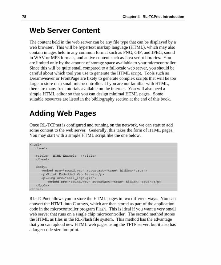
78 Chapter 4. RL-TCPnet Introduction
Web Server Content The content held in the web server can be any file type that can be displayed by a web browser. This will be hypertext markup language (HTML), which may also contain images held in any common format such as PNG, GIF, and JPEG, sound in WAV or MP3 formats, and active content such as Java script libraries. You are limited only by the amount of storage space available to your microcontroller. Since this will be quite small compared to a full-scale web server, you should be careful about which tool you use to generate the HTML script. Tools such as Dreamweaver or FrontPage are likely to generate complex scripts that will be too large to store on a small microcontroller. If you are not familiar with HTML, there are many free tutorials available on the internet. You will also need a simple HTML editor so that you can design minimal HTML pages. Some suitable resources are listed in the bibliography section at the end of this book.
Adding Web Pages Once RL-TCPnet is configured and running on the network, we can start to add some content to the web server. Generally, this takes the form of HTML pages. You may start with a simple HTML script like the one below.
<html> <head> … <title> HTML Example </title> </head> <body> <embed src="sound.wav" autostart="true" hidden="true"> <p>First Emdedded Web Server</p> <p><img src="Keil_logo.gif"> <embed src="sound.wav" autostart="true" hidden="true"></p> </body> </html>
RL-TCPnet allows you to store the HTML pages in two different ways. You can convert the HTML into C arrays, which are then stored as part of the application code in the microcontroller program Flash. This is ideal if you want a very small web server that runs on a single chip microcontroller. The second method stores the HTML as files in the RL-Flash file system. This method has the advantage that you can upload new HTML web pages using the TFTP server, but it also has a larger code-size footprint.
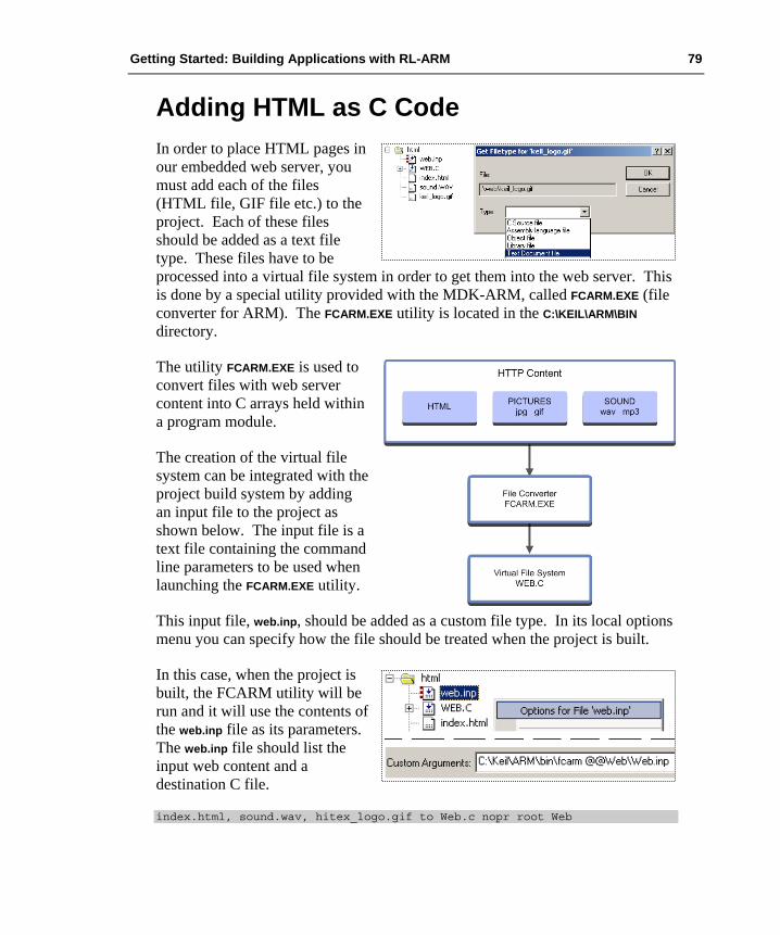
Getting Started: Building Applications with RL-ARM 79
Adding HTML as C Code In order to place HTML pages in our embedded web server, you must add each of the files (HTML file, GIF file etc.) to the project. Each of these files should be added as a text file type. These files have to be processed into a virtual file system in order to get them into the web server. This is done by a special utility provided with the MDK-ARM, called FCARM.EXE (file converter for ARM). The FCARM.EXE utility is located in the C:\KEIL\ARM\BIN directory.
The utility FCARM.EXE is used to convert files with web server content into C arrays held within a program module.
The creation of the virtual file system can be integrated with the project build system by adding an input file to the project as shown below. The input file is a text file containing the command line parameters to be used when launching the FCARM.EXE utility.
This input file, web.inp, should be added as a custom file type. In its local options menu you can specify how the file should be treated when the project is built.
In this case, when the project is built, the FCARM utility will be run and it will use the contents of the web.inp file as its parameters. The web.inp file should list the input web content and a destination C file.
index.html, sound.wav, hitex_logo.gif to Web.c nopr root Web

80 Chapter 4. RL-TCPnet Introduction
When the project is built, the three web-content files are parsed and their contents are stored as C arrays in the file WEB.c.
const U8 index_html [] = { "<html> <head> <title>HTML Example</title></head>\r\n" "<body>\r\n" "<embed src=\"sound.wav\" autostart=\"true\" hidden=\"true\">\r\n" "<p>First Emdedded Web Server</p>\r\n" "<p><img src=\"Keil_logo.gif\">\r\n" "<embed src=\"sound.wav\" autostart=\"true\" hidden=\"true\"></p>\r\n" "</body>\r\n" "</html>\r\n" };
When a web browser connects to the server and requests an HTML page, a simple “file system” is used to locate the correct array. The contents of the array are then returned to the browser, which in turn displays the contents to the user.
const struct http_file FileTab [FILECNT] = { {"index.html", (U8 *) &index_html, 255}, {"sound.wav", (U8 *) &sound_wav, 8903}, {"keil_logo.gif", (U8 *) &keil_logo_gif, 4637}, … };
To make an active web server, you simply add the Web.c file to your project and rebuild the project. This approach embeds the web server content as part of your application. As it does not use a full file system, you can build a very small web server application that will fit within the Flash memory of a small microcontroller. However, once the application is built, it is not possible to update the content of the HTML pages. If you need to change the HTML content of a deployed web server, it is possible to store the HTML pages within the RL-Flash file system. They then can be updated locally or remotely via the TFTP server.
Exercise: First Web Server This exercise configures a minimal Web Server with a single page of HTML.

Getting Started: Building Applications with RL-ARM 81
Adding HTML with RL-Flash The RL-TCPnet web server can be configured to serve web pages stored in a Flash file system implemented with RL-Flash. This makes it possible for users to upload HTML pages into the file system using the TFTP server and then serving them to a web browser. We can configure the web server to work this way by taking the TFTP example from the last section and enabling the HTTP and TCP support.
We have now covered the basic techniques for building an embedded web server using RL-ARM. This allows us to serve static web pages to remote clients. Most embedded web servers host dynamic web pages that provide information relative to the system where they are hosted. Therefore, a means to pass data to/from the web server and the C application code running in the microcontroller is required. In the RL-TCPnet library, this is done through a Common Gateway Interface (CGI).
Exercise: File based web server This exercise configures the web server to store its HTML content within an SD card using the RL-Flash file system. The TFTP server is enabled also so that new pages can be uploaded remotely.

82 Chapter 4. RL-TCPnet Introduction
The Common Gateway Interface The Common Gateway Interface (CGI) is a standard protocol for interfacing application software to a TCP/IP server, typically a HTTP server. The CGI protocol will take data from the TCP/IP server that has been entered from a client and pass it to the application software in the form of an environment variable. The CGI protocol also allows the application software to output data through the TCP/IP server. In the case of a HTTP server, the data is output as dynamically modified HTML.
To enable the CGI interface, we need to add a new C file from the RL-TCPnet library to our project. This file is called HTTP_CGI.C and is stored in the TCPnet source directory C:\KEIL\ARM\RL\TCPNET\SRC. In addition, any HTML file that will access the CGI interface must have the extension .cgi rather than htm or html as shown below.
The file HTTP_CGI.c links events in the web server to the application C code via a CGI.
Dynamic HTML We have already discussed how to display static HTML pages. However, most embedded web servers need to display the data held in the C application.
With the RL-TCPnet, this is done with a simple CGI scripting language that is added to the HTML text. The CGI scripting language contains four basic commands. These must be placed at the beginning of each HTML line within a page that uses the CGI gateway. The commands are as follows:
Command Description
I Include a HTML file and output it to the browser. T The characters following this command are a line of HTML and should be output
to the browser. C This line of text is a command line and the CGI interface will be invoked. . A period ( . ) must be placed at the end of a CGI file. # A hash ( # ) character must be placed before a comment.

Getting Started: Building Applications with RL-ARM 83
An HTML file that is intended to output a dynamically changing greeting message to the web browser would look like this:
t <HTML><HEAD><TITLE> Hello World Example </TITLE></HEAD> t <H2 ALIGN=CENTER> Output a Greeting as Dynamic HTML </H2> c a <p> %s </p> t </BODY> t </HTML> . # The period marks the end of the file
The first two lines begin with the “t” script command. This means that the remainder of the line is HTML and will be sent to the client browser. The third line begins with the “c” script command. This means it is a command line. The remainder of the line will be passed in an environment variable to the common gateway interface function cgi_func(). The environment variable is called env and from the example above it will contain the string “a <p>%s</p>”. The start of this string consists of user defined control characters, in this case the “a”. The cgi_func() must contain code to parse these characters and then format the remainder of the HTML line.
U16 cgi_func (U8 *env, U8 *buf, U16 buflen, U32 *pcgi) { switch (env [0]) { case 'a': len = sprintf ((S8 *) buf, (const S8 *) &env [2], "Hello World"); break; } return ((U16) len); }
In the case above when the page is loaded, the “a” clause of the switch statement will be executed. The sprint() statement then becomes
len = sprintf ((S8 *) buf, <p>%s</p> , "Hello World");
and the contents of buf becomes:
<p> Hello World </p>
which is then output to the browser.
To the browser the HTML code will appear as shown below.
<HTML><HEAD><TITLE>Hello World</TITLE></HEAD> <BODY> <H2 ALIGN=CENTER>Output a Greeting as Dynamic HTML</H2> <p> Hello World </p> </BODY>
84 Chapter 4. RL-TCPnet Introduction
This technique is very straightforward and easy to use. You can apply the CGI scripting to any part of the HTML text, in order to generate dynamically any form of HTML display. In the above example, we have only used one user defined control character. It is possible to use multiple control characters to build up complex dynamic pages.
Exercise: CGI Scripting This exercise demonstrates the basic scripting method used to generate dynamic HTML.
Data Input Using Web Forms Now we will have a look at how to send data from the web browser to the C application. There are two data input methods supported by the CGI module. These two methods are called GET and POST. Both are used to input data through a form.
The GET method should be used if the input data is idempotent. This means that the input data has no observable effect on the world. For example, entering a query into a search engine does not change any data held on the web.
The POST method should be used if the input data is going to be used to change values “in the real world”. For example, if you are entering data into a database you are changing the state of that database and should therefore use the POST method. For our purpose of entering data into a small, embedded web server, we will be using the POST method.
For our purposes, the GET method should be used to change environment variables within the web server, while the POST method should be used to transfer data between the user and the C application code.
Using the POST Method To allow a remote user to enter data via a web browser, we need to add a form cell and a submit button to our web page. The basic code for this is shown below.

Getting Started: Building Applications with RL-ARM 85
<HTML> <HEAD> <TITLE>Post example</TITLE> </HEAD> <BODY> <FORM ACTION="index.cgi" METHOD="POST" NAME="CGI"> <TABLE> <TR> <TD> <INPUT TYPE="TEXT" ID="textbox1" SIZE="16" VALUE=""></TD> <TD ALIGN="right"> <INPUT TYPE="SUBMIT" ID="change" VALUE="change"></TD> </TR> </TABLE> </FORM> </BODY> </HTML>
When this page is viewed, it creates a cell “textbox1” and a submit-button “change” that invokes the POST method. Pressing the button will post the data of “textbox1” to the CGI interface. This causes RL-TCPnet to call the CGI_process_data() function in the HTTP_CGI.c file.
void cgi_process_data (U8 *dat, U16 len) { unsigned char text1 [16]; var = (U8 *) alloc_mem (40); do { dat = http_get_var (dat, var, 40); if (var [0] != 0 ) { if (str_scomp (var, "textbox1") == __TRUE) { str_copy (text1, var+4); // extract user data process_Input (text1); // user function to process data } } } }
The two functions CGI_process_data() and CGI_process_var() are used to handle the GET and POST methods for sending data to a web server. We must customize the CGI_process_data() function in order to take data from the textbox1 cell.
When the SUBMIT button is pressed, RL-TCPnet calls CGI_process_data(). In this function, a buffer called var is allocated. The process data is then copied into this buffer as a string, by calling the http_get_var() function. This string contains the name of the form cell and any data that has been entered. The form of this string is shown below.
textbox1=<input text>

86 Chapter 4. RL-TCPnet Introduction
Now, all we need to do is to add code to parse this string and pass any entered data to our C application.
Exercise: CGI POST Method This exercise used the CGI POST method to pass input data from a text box to the underlying C application.
The basic POST method allows you to input data from any HTML form. However, when the form is reloaded, the default options will be displayed. If you have a configuration page that uses objects such as radio buttons and check boxes, it is desirable to display the current configuration. To do this, we need to employ both the CGI dynamic HTML and the CGI POST method. When the page loads or is refreshed, the CGI_func() must output the current settings. If new values are entered, they will be accepted by the CGI_process_data() function. For a simple text box, the HTML must be modified as follows:
# # HTML with script commands # t <HTML> t <HEAD> t <TITLE>Post example</TITLE> t </HEAD> t <BODY> t <FORM ACTION="index.cgi" METHOD="POST" NAME="CGI"> t <TABLE> t <TR> t <TD> c a <INPUT TYPE="TEXT" ID="textbox1" SIZE="16" VALUE="%"></TD> t <TD ALIGN="right"> t <INPUT TYPE="SUBMIT" ID="change" VALUE="change"></TD> t </TR> t </TABLE> t </FORM> t </BODY> t </HTML>
The CGI_func() must output the current value held in the text box cell when the page is loaded.
// From cgi_func() in HTTP_CGI.c case 'a': len = sprintf ((S8 *) buf, (const S8 *) &env [4], text1); break;

Getting Started: Building Applications with RL-ARM 87
In this case, the data held in the application_data variable will be converted to an ASCII string. When the HTML page is loaded, the string will appear as the content of the text box. This same approach can be applied to any other HTML object such as radio buttons, check boxes, and pick lists.
Using the GET Method The GET method works on the same principle as the POST method. When a form is defined in the HTML script, we use the GET method in place of the POST method as shown below.
<FORM ACTION="network.cgi" METHOD="GET" NAME="CGI">
Now when the form is submitted, the CGI_process_var() function will be triggered in place of the POST method’s CGI_process_data() function. The contents of the input cell are passed to the CGI_process_var() function and can be handled in the same manner as the CGI_process_data() function.
void cgi_process_var (U8 *qs) { U8 *var; var = (U8 *) alloc_mem (40); do { qs = http_get_var (qs, var, 40); if (var [0] != 0) { if (str_scomp (var, "query=" ) == __TRUE) { form_query_string (var+6); } ……… } while (qs); free_mem ((OS_FRAME *) var); } }
Exercise: Web Server Forms This exercise demonstrates the code needed for each of the basic web form objects including text box, radio button, check box and selection list.

88 Chapter 4. RL-TCPnet Introduction
Using JavaScript JavaScript is a C like scripting language stored on a web server and downloaded on demand to a client browser. The client interprets and executes the script on its host processor, be this a PC, MAC, or smartphone. JavaScript allows you to develop sophisticated multi-platform user interfaces. In this section, we will look at adding a JavaScript library that draws a graph. First, we need a suitable JavaScript application. A graph drawing application can be downloaded from www.codeproject.com/jscript/dhtml_graph.asp. This object consists of two files, a JavaScript source file, and a gif. Add them to a web server application. The web.inp file content is:
index.htm, graph.htm, dot.gif, graph.js to Web.c nopr root Web
The three graph files (graph.htm, dot.gif, and graph.js) are also added to the web.inp command line. The HTML file graph.htm invokes the graph object.
<script language="JavaScript"> var bg = new Graph (10); bg.parent = document.getElementById ('here'); bg.title = 'Annual average temperature by month'; bg.xCaption = 'Month'; bg.yCaption = 'Temperature';
bg.xValues [0] = [10, 'Jan']; bg.xValues [1] = [15, 'Feb']; bg.xValues [2] = [17, 'March']; bg.xValues [3] = [20, 'April']; bg.xValues [4] = [22, 'May']; bg.xValues [5] = [30, 'June']; bg.xValues [6] = [33, 'July']; bg.xValues [7] = [27, 'Aug']; bg.xValues [8] = [20, 'Sept']; bg.xValues [9] = [18, 'Oct']; bg.xValues [10] = [15, 'Nov']; bg.xValues [11] = [9, 'Dec'];
bg.showLine = true; bg.showBar = true; bg.orientation = 'horizontal'; // or = 'vertical';
bg.draw (); </script>

Getting Started: Building Applications with RL-ARM 89
When the html page is loaded, the JavaScript library is sent to the browser client. The HTML code is used to create the graph object and define the coordinates.
When the graph page is loaded, the JavaScript code will be downloaded to the browser. The browser will then execute the JavaScript code and draw the graph. This results in a “static” graph where always the same values are plotted. While this is not very useful in an embedded system, it is a good starting point to test the JavaScript source code, particularly if you have not written it yourself. Once the JavaScript is running as a static object, the RL-TCPnet scripting commands can be used to pass data from the embedded application to the JavaScript graph. First, we must rename the graph.htm file to graph.cgi then add the script commands as shown below.
c m a bg.xValues [0] = [%s, 'Jan']; c m b bg.xValues [1] = [%s, 'Feb']; c m c bg.xValues [2] = [%s, 'March']; c m d bg.xValues [3] = [%s, 'April']; c m e bg.xValues [4] = [%s, 'May']; c m f bg.xValues [5] = [%s, 'June']; c m g bg.xValues [6] = [%s, 'July']; c m h bg.xValues [7] = [%s, 'Aug']; c m i bg.xValues [8] = [%s, 'Sept']; c m j bg.xValues [9] = [%s, 'Oct']; c m k bg.xValues [10] = [%s, 'Nov']; c m l bg.xValues [11] = [%s, 'Dec'];
// // From HTTP_CGI.c // unsigned char months [12] = {10, 15, 17, 20, 22, 30, 33, 27, 20, 18, 15, 9}; U16 cgi_func (U8 *env, U8 *buf, U16 buflen, U32 *pcgi) { … case 'm': i = env [2] - 0x61; sprintf (buffer, "%1d", months [i]); len = sprintf ((S8 *) buf, (const S8 *) &env [4], buffer); break; …… }
90 Chapter 4. RL-TCPnet Introduction
Here we want to display temperature values held in a C array controlled by the application code. We add a script command for each line of JavaScript that is used to pass the graph coordinates. The fixed graph values are replaced by a %s for the dynamic data. When the page is loaded, each script line will trigger the cgi gateway function cgi_func(). A second user defined command is added for each script line (a to l). Each time the script command triggers, the cgi_func() is called and we enter case ’m’: of the switch statement. The ASCII value of the second user defined character is read from the env[] array and we deduct 0x61. This converts from an ASCII character value to a binary value between 0 and 11. This value is used as an index into the application data array (months[]). The logged temperature data is then converted into an ASCII string. Finally, the sprintf() command is used to replace the %s in the HTML code with the application data value. The result is a graph that displays the dynamic data logged by the application. Using this approach, you can see that web server scripting commands in TCPnet allow you to pass dynamic application data to any embedded object.
Exercise: JavaScript This exercise demonstrates adding a JavaScript Graph object to a CGI page.
AJAX Support Using the RL-TCPnet scripting language to pass dynamic data to JavaScript objects allows you to easily build sophisticated html pages that utilize the thousands of man hours of development that has gone into many web browsers. However, there are disadvantages if you are trying to display frequently changing data. An easy solution is for the user to press the browser’s refresh button or you can add a refresh tag to the <head> section of the HTML code.
<meta http-equiv = "refresh" content="600">
While this works, it is not very satisfactory for two reasons. First, this causes the whole page to reload, what causes screen flicker and thus is not very satisfactory for the user. Second, the browser has to download the whole page again, which is slow and consumes bandwidth. The solution to this problem is to use a group of interrelated web development techniques called “Asynchronous JavaScript and XML” or Ajax for short. For our purposes, Ajax is used to isolate the dynamic data within a group of XML tags. This data is then sent to the browser at an update rate defined within the html page. This means that the dynamic application data is sent in a single TCP packet providing a very fast update rate

Getting Started: Building Applications with RL-ARM 91
that consumes minimal bandwidth. The most commonly used browsers can take this data and update the web page without having to reload the full page. This gives flicker free “real-time” update of dynamic objects within the web page.
To see how the Ajax support works within RL-TCPnet, we will look at creating a CGI page that contains eight tick boxes that reflect the state of a series of buttons connected to port pins on the user hardware. The necessary Ajax JavaScript support is contained in a support file called xml_http.js. This file should be added to a web server project as shown above. Next, we must create a CGI page, buttons.cgi, that displays the eight check boxes. A separate XML file, buttons.cgx, is also created that will hold the dynamic data as XML tags.
#------------------------------------------------ # HTML script in buttons.cgi #------------------------------------------------
t <form action="buttons.cgi" method="post" id="form1" name="form1"> t <table border="0" width="99%"><font size="3"><tr> t <td><img src="pabb.gif">Buttons [7..0]:</td> t <td align="center"> t <input type="checkbox" disabled id="button7">7 t <input type="checkbox" disabled id="button6">6 t <input type="checkbox" disabled id="button5">5 t <input type="checkbox" disabled id="button4">4 t <input type="checkbox" disabled id="button3">3 t <input type="checkbox" disabled id="button2">2 t <input type="checkbox" disabled id="button1">1 t <input type="checkbox" disabled id="button0">0 t </td> t </tr></font></table> t <p align="center"> t <input type="button" id="refreshBtn" value="Refresh" onclick="updateMultiple(formUpdate)"> t Periodic:<input type="checkbox" id="refreshChkBox" onclick="periodicUpdate()"></p></form>
A refresh button, a tick box, and eight status boxes are created in a form that uses the post method. The refresh button will invoke a JavaScript function, updateMultiple(). Checking the periodic tick box will call a separate JavaScript function, periodicUpdate().

92 Chapter 4. RL-TCPnet Introduction
/*------------------------------------- * xml_http.js *------------------------------------*/ function periodicObj (url, period) { this.url = url; this.period = (typeof period == "undefined") ? 0 : period; }
#-------------------------------------- # buttons.cgi #-------------------------------------- t var formUpdate = new periodicObj ("buttons.cgx", 300);
/*---------------------------------------- * xml_http.js *---------------------------------------*/ function updateMultiple (formUpd, callBack, userName, userPassword) { xmlHttp = GetXmlHttpObject(); if (xmlHttp == null) { alert ("XmlHttp not initialized!"); } return 0; }
When the refresh button is pressed, the JavaScript function updateMultiple() is downloaded from the server and executed in the browser. This is a standard function in the xml_http.js support file. When this function is invoked, a parameter called formUpdate is passed. This is an instance of a JavaScript object called periodicObj that is also defined in xml_http.js. This object passes the name of the xml file that has to be downloaded, as well as the update period measured in msec.
#-------------------------------------- # Buttons.cgx #-------------------------------------- t <form> c y0 c y1 c y2 c y3 c y4 c y5 c y6 c y7 t </form> .

Getting Started: Building Applications with RL-ARM 93
/*--------------------------------------- * cgi_func() in HTTP_CGI.c *--------------------------------------*/ case 'y': len = sprintf ( (char*) buf, "<checkbox><id><button%c</id> <on>%s</on></checkbox>", env [1], (get_button () & (1<<(env [1]-'0'))) ? "true" : "false" ); break;
<!----------------------------------------- # Generated XML #-----------------------------------------> <form> <checkbox><id>button0</id><on>true</on></checkbox> <checkbox><id>button1</id><on>false</on></checkbox> <checkbox><id>button2</id><on>false</on></checkbox> <checkbox><id>button3</id><on>false</on></checkbox> <checkbox><id>button4</id><on>false</on></checkbox> <checkbox><id>button5</id><on>false</on></checkbox> <checkbox><id>button6</id><on>false</on></checkbox> <checkbox><id>button7</id><on>false</on></checkbox> </form>
This causes the browser to download the buttons.cgx file, which is a small file containing a script line for each element of the form. Each script line causes cgi_func() to execute. The user defined command letters cause case y in the switch statement to execute. This code then constructs the necessary XML to update the browser tick-boxes and reflect the current status of the buttons on the user hardware.
It is important to note that there should be no space characters in the generated XML code.
#-------------------------------------- # buttons.cgi #-------------------------------------- t function periodicUpdate() { t if (document.getElementById ("refreshChkBox").checked == true) { t updateMultiple (formUpdate); t periodicFormTime = setTimeout ("periodicUpdate ()",formUpdate.period); t } else { t clearTimeout (periodicFormTime); t } t }
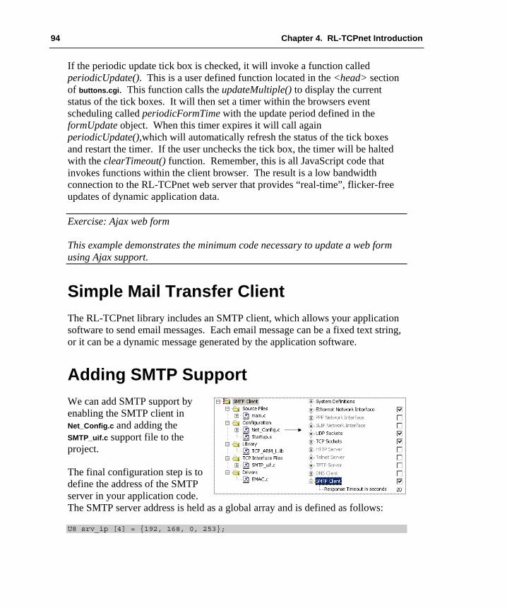
94 Chapter 4. RL-TCPnet Introduction
If the periodic update tick box is checked, it will invoke a function called periodicUpdate(). This is a user defined function located in the <head> section of buttons.cgi. This function calls the updateMultiple() to display the current status of the tick boxes. It will then set a timer within the browsers event scheduling called periodicFormTime with the update period defined in the formUpdate object. When this timer expires it will call again periodicUpdate(),which will automatically refresh the status of the tick boxes and restart the timer. If the user unchecks the tick box, the timer will be halted with the clearTimeout() function. Remember, this is all JavaScript code that invokes functions within the client browser. The result is a low bandwidth connection to the RL-TCPnet web server that provides “real-time”, flicker-free updates of dynamic application data.
Exercise: Ajax web form This example demonstrates the minimum code necessary to update a web form using Ajax support.
Simple Mail Transfer Client The RL-TCPnet library includes an SMTP client, which allows your application software to send email messages. Each email message can be a fixed text string, or it can be a dynamic message generated by the application software.
Adding SMTP Support We can add SMTP support by enabling the SMTP client in Net_Config.c and adding the SMTP_uif.c support file to the project.
The final configuration step is to define the address of the SMTP server in your application code. The SMTP server address is held as a global array and is defined as follows:
U8 srv_ip [4] = {192, 168, 0, 253};

Getting Started: Building Applications with RL-ARM 95
Sending a Fixed Email Message Once the server has been configured, the application starts the SMTP client by calling the smtp_connect() function. This function connects to an SMTP server, sends a single email, disconnects from the server, and finally calls a callback function.
smtp_connect ((U8 *) &srv_ip, 25, smtp_cback);
Smtp_connect() requires three parameters. The first parameter is the SMTP server IP address. The second parameter is the port number on that the SMTP server is running; the standard, well-known SMTP port is “25”. Finally, we pass the name of the function that will be called when the SMTP session finishes.
The email message is composed by the smtp_connect() function by calling the user-defined SMTP client interface function smtp_cbfunc() stored in the SMTP_uif.c file:
U16 smtp_cbfunc (U8 code, U8 *buf, U16 buflen, U16 *pvar xcnt)
During the SMTP session, this function is called several times. Each time it is called, a different code is passed. This is in order to request a different element of the email message: sender’s email address, destination address, subject, and finally the message. Each part of the message must be copied into the buffer, which is passed as the second parameter. The third parameter passes the maximum size of the message buffer. This will vary depending on the underlying maximum segment size of the TCP/IP network. A very simple message can be sent as follows:
switch (code) { case 0: //senders email address len = str_copy (buf, "[email protected]"); break; case 1: //recipient email address len = str_copy (buf, "[email protected]); break; case 2: //subject line len = str_copy (buf, "Hello RL-TCPnet"); break; case 3: //message len = str_copy (buf, "Email from RL-TCPnet."); break; }

96 Chapter 4. RL-TCPnet Introduction
The final message string must be terminated with a period (.). Once the message has been, sent the SMTP session will end and the user-defined callback function will be called. A session code will be passed to the callback function. This reports whether the SMTP session was successful and if not, why it failed.
static void smtp_cback (U8 code) { switch (code) { case SMTP_EVT_SUCCESS: printf ("Email successfully sent\n"); sent = __TRUE; break; case SMTP_EVT_TIMEOUT: printf ("Mail Server timeout.\n"); break; case SMTP_EVT_ERROR: printf ("Error sending email.\n"); break; } }
Exercise: Simple SMTP This exercise presents the minimal code required to send a fixed email message.
Dynamic Message It is possible to send dynamically created email messages. The sender and recipient email addresses and the subject can be held as strings, so that different addresses and subjects can be selected. The application software can also dynamically generate the data sent in the message.
It is possible to send long email messages that contain application data. For each call to the smtp_cbfunc() function, we can only send a packet of data with the size of the buffer buf. However, we can force multiple calls to the smtp_cbfunc() and build an email message that is larger than the buffer size.
typedef struct { U8 id; U16 idx; } MY_BUF; #define MYBUF(p) ((MY_BUF *) p)
First, we must declare a simple structure to control the construction of the email data packets. In the structure above, the idx element counts the number of packets sent, and id controls the flow of the smtp_cbfunc() switch statement.

Getting Started: Building Applications with RL-ARM 97
Next, expand the case 5 switch statement of the smtp_cbfunc() function, to handle multiple data packets. Add another switch statement as shown in the code below. The local buffer MYBUF(pvar)-->id counts how many data packets have been sent, and MYBUF(pvar)-->id controls the flow of the code through the new switch statement. The smtp_cbfunc returns the number of bytes that have been written to the output buffer. Recurring calls to the smtp_cbfunc() function can be enforced by setting the most significant bit of the return value to high.
U16 smtp_cbfunc (U8 code, U8 *buf, U16 buflen, U32 *pvar) { U32 len = 0; switch (code) { … case 5: switch (MYBUF(pvar)->id) { case 0: len = str_copy (buf, "First Packet of Data\n"); MYBUF (pvar)->id = 1; MYBUF (pvar)->idx = 1; goto rep; case 1: len = str_copy (buf,"Bulk of the data\n"); if (++MYBUF(pvar)->idx > 5) { MYBUF(pvar)->id = 2; } /* Request a repeated call, bit 15 is a repeat flag. */ rep: len |= 0x8000; break;
case 2: /* Last one, add a footer text to this email. */ len = str_copy (buf,"Last Packet of data.\n"); break; } } return ((U16) len); }
Therefore, to send an email with a large amount of data we add a new switch statement with cases. The first case sends the initial packet of data and sets the repeat flag, the second case sends the bulk of the data and sets the repeat flag. The final case sends the final packet of data and does not set the repeat flag.
Exercise: Dynamic SMTP This exercise demonstrates how to construct a long email message containing dynamic data.

98 Chapter 4. RL-TCPnet Introduction
It is only possible to send the first 127 ASCII text characters as part of an email message. If you plan to send binary data in an email message, it must be encoded as a text string. The most common way of doing this is to use base64 encoding. The following example demonstrates an encoder and decoder utility.
Exercise: Base64 Encoding This exercise demonstrates a base64 encoder, which can be used to prepare binary data for inclusion in an email message.
Telnet Server The RL-TCPnet library allows you to add a Telnet server to your application. Within the Telnet server, you can provide a custom menu system that links directly to your application C code. This code exists in the telnet support file. Once added, the telnet server is fully functional, including buffering of the command history. The Telnet server has a very small code footprint. This makes it ideal for designs that need remote connectivity having very little Flash memory available. A PC running a Telnet client can then access the Telnet server. This approach gives similar functionality to a HTTP server, but with a much smaller code footprint.
Like the other RL-TCPnet applications, we need to enable the Telnet server in the Net_Config.c module. Once enabled, we can also define the number of parallel connections and if necessary, add password protection. All of the custom code for the Telnet server is held in the user interface file Telnet_uif.c. This file consists of two functions: tnet_cgfunc() and tnet_process_cmd().
U16 tnet_cbfunc (U8 code, U8 *buf, U16 buflen)
The first function, tnet_cbfunc(), is used to manage the password logon to the Telnet server. It also prints the logon banner and the prompt string that is printed at the beginning of each line in the Telnet terminal. You will not need to change the code in this function, but you can change the strings to customize the appearance of the Telnet server.
U16 tnet_process_cmd (U8 *cmd, U8 *buf, U16 buflen, U16 xcnt)

Getting Started: Building Applications with RL-ARM 99
The second function is telnet_process_cmd(). This command line parser is used to read the input from the Telnet client and then calls the required C application functions. When a client connects to the Telnet server and enters a command string, the telnet_process_cmd() function is triggered. The cmd pointer can access the command string entered by the client.
Any reply by the Telnet server must be entered into the buffer buf. The size of this buffer depends on the network maximum segment size. The third parameter, buflen, contains the current maximum size for the buffer buf. Within this function, we must make a command line parser. This will be used to inter-operate the Telnet client commands and call the C application functions.
if (tnet_ccmp (cmd, "ADIN") == __TRUE) { if (len >= 6) { sscanf ((const S8 *)(cmd+5), "%d",&ch); val = AD_in (ch); len = sprintf ((S8 *) buf, "\r\n ADIN %d = %d", ch, val); return (len); } }
When the telnet_process_cmd() function is triggered, we can use the helper function tnet_ccmp() to examine the contents of the command buffer cmd. In the above example, the client command ADIN requests the current conversion value for a selected ADC channel. It is important to note that the helper function tnet_ccmp() converts the command string characters to uppercase. This means, that all your menu options must be defined as uppercase strings. The example parses the string to determine which channel is required. Then it calls the user ADC() conversion function. Next, it places the results in the reply buffer, which is then sent back to the Telnet client. Finally, the number of bytes written into the reply buffer must be returned to the RL-TCPnet library.
if (tnet_ccmp (cmd, "BYE") == __TRUE) { len = str_copy (buf, "\r\nDisconnect...\r\n"); return (len | 0x8000); }
As well as returning the number of bytes in the reply buffer, the most significant bit of the return value acts as a disconnect flag. Setting this bit terminates a Telnet session.
Exercise: Telnet Server This exercise demonstrates a Telnet server with a simple command line parser.
100 Chapter 4. RL-TCPnet Introduction
In a simple Telnet server, the amount of data that can be sent to the Telnet client is limited by the size of the reply buffer buf. However, it is possible to force the RL-TCPnet library to make multiple calls to the telnet_process_cmd() function. Then, with each pass through the telnet_process_cmd() function, we can fill the reply buffer, in order to send multiple packets of data to the client.
U16 tnet_process_cmd (U8 *cmd, U8 *buf, U16 buflen, U16 xcnt) { U16 len = 0; if (repeatcall) { len |=0x4000; } return(len); }
The tnet_process_cmd() function return value contains a repeat flag. The repeat flag is bit 14. When this bit is set, the RL-TCPnet library will make another call to the tnet_process_cmd() function. Each time this function is called, the fourth parameter, xcnt, will be incremented by one. By using the repeat flag and the pass counter xcnt, the parsing code can send large amounts of data to the Telnet client.
Exercise: Telnet Server This exercise extends the basic parser used in the last example to send a long reply to a client.
Telnet Helper Functions In addition to the tnet_cbfunc() and tnet_process_cmd() functions, there are several custom helper functions. We have already seen the tnet_ccmp() function. This is similar to strcmp(), except that it only compares the string contents up to the first NULL or space character. Be careful with this function, as all the characters in the string to be searched are converted to uppercase. The Telnet server may also determine the MAC and IP address of the client PC. These values are entered into a structure by calling the tnet_get_info() function.
/*-------------------------------------- * net_config.h *--------------------------------------*/ typedef struct remotem { U8 IpAdr [IP_ADRLEN]; //client IP address U8 HwAdr [ETH_ADRLEN]; //Client MAC address } REMOTEM;

Getting Started: Building Applications with RL-ARM 101
/*-------------------------------------- * telnet_uif.c *--------------------------------------*/ RMOTEM user; tnet_get_info(&user);
It is also possible to continuously send data from the Telnet server to the client, without requests from the Telnet client. The tnet_set_delay() function can be used to ensure that the RL-TCPnet library calls the tnet_process_cmd() function with a set periodic delay. The resolution of the delay period is the same as the timer tick period. The standard value for this is 100ms.
len = sprintf (buf, "ADIN0 = %d",AD_in (0));
tnet_set_delay (20); // Delay for 2 seconds (20 * 100ms) len |= 0x4000; // Request a repeated call; bit 14 is a repeat flag.
Exercise: Telnet Server Helper Functions This exercise demonstrates the Telnet Server Helper Functions.
DNS Client The RL-TCPnet library contains a Domain Name System (DNS) client. The DNS client is used to access a DNS server and resolve a symbolic address to a numeric IP address. One typical application for the DNS client would be to convert a configuration string entered by a human to a usable IP address, for example post.keil.com.
To configure the DNS client we must first enter the IP address of a primary and secondary DNS server in the Net_Config.c file. These values are not necessary if the Dynamic Host Configuration Protocol (DHCP) client is enabled. This is because the DHCP server will provide these addresses when the DHCP client leases an IP address. Next, enable the DNS client in the Net_Config.c file.
The DNS cache table size defines the maximum number of DNS records that can be held by the DNS client. Each record relates the symbolic address to the

102 Chapter 4. RL-TCPnet Introduction
numeric IP address. Each record is 12 bytes in size. Once the DNS client has been configured, we can resolve a symbolic address by calling the get_host_by_name() function.
get_host_by_name ("www.keil.com", dns_cbfunc);
This function takes the host symbolic name as a string and also the address of a user-defined call back function. Once invoked, the DNS client will attempt to resolve the address by contacting the DNS server. The results will be passed to the call back function.
static void dns_cbfunc (unsigned char event, unsigned char *ip) { switch (event) { case DNS_EVT_SUCCESS: // Success: IP address pointed at by *ip break; case DNS_EVT_NONAME: // Name does not exist in DNS database. break; case DNS_EVT_TIMEOUT: // DNS sever timeout break; case DNS_EVT_ERROR: // DNS protocol error return; } }
Exercise: DNS Resolver This exercise takes symbolic host addresses entered via a web page and resolves the IP addresses.
Socket Library The RL-TCPnet supports the internet applications, which are most useful to a small, embedded system. However, you may wish to use the microcontroller’s Ethernet peripheral for a custom application. For example, you may wish to use the Ethernet peripheral for high-speed board-to-board communication within a distributed control system. A number of industrial communication protocols, such as PROFINET or MODBUS/TCP, use TCP/IP as their base communication protocol. If you do wish to make a custom protocol, then RL-TCPnet has a low level “Sockets” API. This allows you to send and receive raw TCP and UDP frames. To demonstrate how the Sockets Library is used, we will establish a TCP/IP link between two microcontrollers and send custom data packets as UDP and TCP frames.

Getting Started: Building Applications with RL-ARM 103
User Datagram Protocol (UDP) Communication In this first example, we will connect two boards together through an Ethernet crossover cable. The boards will communicate by sending packets of data as UDP frames.
The Sockets API is a standard part of the RL-TCPnet library, so we can use our first example PING project as a starting point. Then we just need the UDP protocol to be enabled. UDP is a half-duplex bi-directional protocol. This means that we can establish a single connection between two IP addresses and two ports. We can then send and receive data packets between the two stations over this single channel.
socket_udp = udp_get_socket (0, UDP_OPT_SEND_CS|UDP_OPT_CHK_CS, udp_callback);
First we must call udp_get_socket(). We pass the type of service to this function. This is not widely used, so we enter the default value zero. We can also opt to generate and check the UDP packet checksum. Next, we pass the address of a callback function, which will be called if a packet is received. Once called, this function will return a handle to a free socket.
udp_open (socket_udp, 1001);
Once we have a free socket, we can open a UDP port for communication.
U8 *sendbuf;
When the port is open, we can send and receive UDP packets. To send a packet, we must first acquire a UDP packet data frame. To do this we call the udp_get_buf() function and pass the size of the data packet that we want to send. This can be up to the maximum Ethernet frame size of 1500 bytes. This function then returns a pointer to the data packet buffer. Next, we use this pointer to write our application data into the UDP packet.
udp_send (socket_udp, Rem_IP, 1001, sendbuf, SENDLEN);
104 Chapter 4. RL-TCPnet Introduction
Once the data has been written into the packet, we can use udp_send() to transmit it. When we call the udp_send() function, we must pass the socket handle, the remote IP address, the remote port, the buffer pointer and the data packet size. This will cause RL-TCPnet to send the frame. The UDP protocol is a “best effort” protocol. This means that once the packet is sent there is no acknowledgement or handshake from the destination station. If you require a positive acknowledgement that the packet was received, then the destination station must send a reply UDP frame.
U16 udp_callback (U8 soc, U8 *rip, U16 rport, U8 *buf, U16 len) { if (soc == socket_udp) { Process_packet (buf,len); } return (0); }
To receive the UDP data packets the destination station must make the same “get socket” and “port open” calls. This will ensure that it is listening for the UDP packet. When a packet arrives, it is processed by the RL-TCPnet and the udp_callback() function is triggered. This function receives the local socket handle, the remote IP address, and the port number of the sending station. It also receives a pointer to the received data along with the number of bytes received. The destination station can then reply back to the source station using its IP address and port number.
Exercise: UDP Sockets This exercise demonstrates peer-to-peer communication between two evaluation boards using the UDP protocol.
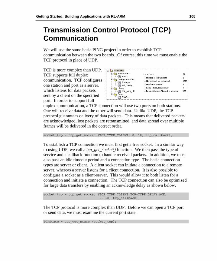
Getting Started: Building Applications with RL-ARM 105
Transmission Control Protocol (TCP) Communication We will use the same basic PING project in order to establish TCP communication between the two boards. Of course, this time we must enable the TCP protocol in place of UDP.
TCP is more complex than UDP. TCP supports full duplex communication. TCP configures one station and port as a server, which listens for data packets sent by a client on the specified port. In order to support full duplex communication, a TCP connection will use two ports on both stations. One will receive data and the other will send data. Unlike UDP, the TCP protocol guarantees delivery of data packets. This means that delivered packets are acknowledged, lost packets are retransmitted, and data spread over multiple frames will be delivered in the correct order.
socket_tcp = tcp_get_socket (TCP_TYPE_CLIENT, 0, 10, tcp_callback);
To establish a TCP connection we must first get a free socket. In a similar way to using UDP, we call a tcp_get_socket() function. We then pass the type of service and a callback function to handle received packets. In addition, we must also pass an idle timeout period and a connection type. The basic connection types are server or client. A client socket can initiate a connection to a remote server, whereas a server listens for a client connection. It is also possible to configure a socket as a client-server. This would allow it to both listen for a connection and initiate a connection. The TCP connection can also be optimized for large data transfers by enabling an acknowledge delay as shown below.
socket_tcp = tcp_get_socket (TCP_TYPE_CLIENT|TCP-TYPE_DELAY_ACK, 0, 10, tcp_callback);
The TCP protocol is more complex than UDP. Before we can open a TCP port or send data, we must examine the current port state.
TCPState = tcp_get_state (socket_tcp);
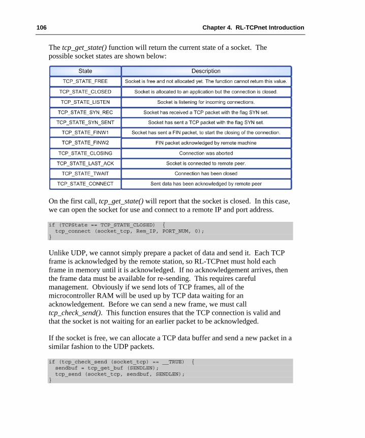
106 Chapter 4. RL-TCPnet Introduction
The tcp_get_state() function will return the current state of a socket. The possible socket states are shown below:
On the first call, tcp_get_state() will report that the socket is closed. In this case, we can open the socket for use and connect to a remote IP and port address.
if (TCPState == TCP_STATE_CLOSED) { tcp_connect (socket_tcp, Rem_IP, PORT_NUM, 0); }
Unlike UDP, we cannot simply prepare a packet of data and send it. Each TCP frame is acknowledged by the remote station, so RL-TCPnet must hold each frame in memory until it is acknowledged. If no acknowledgement arrives, then the frame data must be available for re-sending. This requires careful management. Obviously if we send lots of TCP frames, all of the microcontroller RAM will be used up by TCP data waiting for an acknowledgement. Before we can send a new frame, we must call tcp_check_send(). This function ensures that the TCP connection is valid and that the socket is not waiting for an earlier packet to be acknowledged.
If the socket is free, we can allocate a TCP data buffer and send a new packet in a similar fashion to the UDP packets.
if (tcp_check_send (socket_tcp) == __TRUE) { sendbuf = tcp_get_buf (SENDLEN); tcp_send (socket_tcp, sendbuf, SENDLEN); }

Getting Started: Building Applications with RL-ARM 107
On the server side, we must get a socket and configure it as a server. Then we need to open a port to listen for a client connection.
socket_tcp = tcp_get_socket (TCP_TYPE_SERVER, 0, 10, tcp_callback); if (socket_tcp != 0) { tcp_listen (socket_tcp, PORT_NUM); }
When a remote node sends a TCP packet, it will be received by RL-TCPnet and the callback function will be triggered.
U16 tcp_callback (U8 soc, U8 evt, U8 *ptr, U16 par) { return (0); }
This function is passed the socket handle, a pointer to the data packet and the number of bytes in the data packet. Tcp_callback() is also passed an event code evt. The evt code specifies the type of TCP connection event.
When a remote station first connects to the TCP server, port tcp_callback() will be triggered with the TCP_EVT_CONREQ condition. In this case, the pointer, par, points to the IP address of the remote station. The parameter par holds the remote port number. If the server wants to refuse connection to the remote station, it can return 0x00 and the connection will be closed. Otherwise it will return 0x01. All other states should return 0x00. Once the connection has been accepted, any valid TCP packet will trigger the TCP_EVT_DATA condition and the packet data can be read from the frame buffer.
Exercise: TCP Sockets This exercise demonstrates client-server communication between two evaluation boards, using the UDP protocol. A second example uses a TCP socket to get the current date and time from a remote daytime server.

108 Chapter 4. RL-TCPnet Introduction
Deployment During development you can use the default Media Access Control (MAC) address provided in Net_Config.c. However, when you come to manufacture your final product, each unit you are making must have a unique MAC address. It is possible to purchase a block of 4096 MAC addresses from the IEEE web site. This is called an Individual Address Block (IAB). If you plan to use more than 4096 MAC addresses, you can buy an Organizational Unique Identifier, which gives you 0x1000000 MAC addresses. For more details, see the IEEE web site at http://standards.ieee.org/regauth/oui/index.shtml.
During production, there are two strategies for programming the MAC address of each unit. You can initially program each unit with the same code and MAC address. Then, during the final test phase, the MAC address can be reprogrammed to a unique value. This can be done by adding some additional code to your application for this purpose.
Alternatively, the MAC address can be located to a fixed address in its own linker segment. In the compiler tool chain, the ElftoHex.exe converter takes the output of the linker and generates a HEX file. This utility can produce a HEX file for each program segment. This means that we can have all our program code in one segment. Only the MAC address is in a separate HEX file. Thus, we can burn the program HEX file into each unit and then increment and program the MAC address separately. This method is also useful if your microcontroller has a One-Time Programmable (OTP) memory region, which is programmed separately from the main Flash memory.
Exercise: MAC Programming This exercise demonstrates generating a program HEX file and a MAC address HEX file for production programming.

Getting Started: Building Applications with RL-ARM 109
Serial Drivers Although most RL-TCPnet applications will connect to a TCP/IP network using an Ethernet interface, it is also possible to use a UART connected to a modem to establish a Serial Line Internet Protocol (SLIP) or Point-to-Point (PPP) connection with the network.
In order to configure the RL-TCPnet library to establish a PPP connection, you must enable the PPP support in Net_Config.c first. Like the Ethernet interface, the PPP interface allows you to define the IP address, subnet, and the DNS server. It also gives you the option of having them assigned automatically by the PPP host.
In addition to these basic parameters, we can also define a character map, which defines replacement strings for characters used for modem and flow control. If you are communicating with a modem or using software flow control, it is necessary to send control characters alongside the data packets. The values used for the control characters may not be sent in the data packets. We must encode the values used as control characters, in order to send them in a data packet. For example, if we are using the Xon/Xoff software flow control, the value 0x11 is used to start the serial data stream, 0x13 is used to halt it.
To allow the values 0x11 and 0x13 to be sent as part of a data packet, we must define a two-byte encoding that replaces each instance of these values in the data stream. The encoding used in SLIP and PPP protocols is the ASCII escape character (0x7D), followed by the value to be encoded XORed with 0x20.
XON = 0x11 Async control character = 0x31 XOFF = 0x13 Async control character = 0x33
When a data packet contains 0x11 it will now be replaced with 0x7D 0x31.

110 Chapter 4. RL-TCPnet Introduction
We must also replace the Ethernet driver with a serial driver. Serial drivers for supported microcontrollers are located in C:\KEIL\ARM\RL\TCPNET\DRIVERS.
The serial driver contains four functions. The first, init_serial(), initializes the selected UART to a defined baud rate. The next two functions, com_getchar() and com_putchar(), are used to read and write a single character to the UART. These are both interrupt-driven functions, whose purpose is to ensure that there is no loss of data at high data rates. The final function is com_tx_active(), which is used to check if the UART is transmitting data.
Once the serial driver has been added, we can use RL-TCPnet in exactly the same way as we would use an Ethernet-based system. However, there are some dedicated SLIP and PPP functions, which are used to establish the serial connection. If the RL-TCPnet application is acting as a client, it must actively open a connection to the server. In this case there are two functions, ppp_connect() and slip_connect(), which dial up a remote system.
ppp_listenconnect ("024345667", "<user>", "<password>"); slip_connect ("024345667");
In the case of the PPP protocol, we must also pass a username and a password. For a server application, there are two listen functions that initialize the connection and wait for a client to connect.
ppp_listen(); slip_listen();
Once connected, we can monitor the state of the SLIP or PPP link using the two functions below:
ppp_is_up(); slip_is_up();
Both these functions return TRUE if the serial link is working, or FALSE if it has been lost. Once we have finished with the serial connection, it must be closed using the either of the functions below:
ppp_close(); slip_close();
Exercise: PPP Connection This exercise demonstrates replacing the Ethernet driver with a serial driver configured for the Point-to-Point protocol.

Getting Started: Building Applications with RL-ARM 111
Chapter 5. RL-USB Introduction Today the Universal Serial Bus (USB) is the standard way to connect external peripherals to a Personal Computer (PC). Consequently, if you are designing an embedded system that has to interact with a PC, your customers will expect it to use a USB port. Although USB is not a simple protocol, the process of designing a USB peripheral has become a lot easier over the last few years. In this chapter, we will outline the key concepts of the USB protocol. Afterwards we will consider using the RL-USB driver to design a number of USB-based peripherals. The USB driver in RL-ARM can be used standalone or with RTX.
The USB Protocol – Key Concepts The USB protocol was first introduced in 1996. It is supported by the Windows operating system from Windows 2000 onwards. USB is a high-speed serial interface designed to be “plug and play” making it easier to add peripherals. It aims to allow end users to build sophisticated computing systems without having to worry about the underlying technology. This ease of use comes at the expense of a great deal of design complexity. To design USB peripherals, you need to understand the microcontroller firmware, the USB protocol, the USB Device Classes and the USB host operating system. This is much easier now that the USB protocol has reached a mature stage of adoption.
USB Physical Network The USB network supports three communication speeds. Low speed runs at 1.5 Mbit/s and is primarily used for simple devices like keyboards and mice. Full speed runs at 12 Mbit/s and is suitable for most other peripherals. Finally, High speed runs at 480 Mbit/s and is aimed at video devices that require high bandwidth.

112 Chapter 5. RL-USB Introduction
The physical USB network is implemented as a tiered star network. The USB host provides one attachment port for an external USB peripheral. If more than one peripheral is required, connect a hub to the root port and the hub will provide additional connection ports. For a large number of USB peripherals add further hubs to provide the ports needed. The USB network can support up to 127 external nodes (hubs and devices). It supports six tiers of hubs and requires one bus master.
Each hub or device may be self-powered or bus-powered. If a device is bus-powered, it can consume a maximum of 500mA at 5V.
Logical Network To the developer the logical USB network appears as a star network. The hub components do not introduce any programming complexity and are essentially transparent as far as the programmer is concerned. Therefore, if you develop a USB device by connecting it to a root port on the host, the same device will work when connected to the host via several intermediate hubs.
To the programmer the USB network appears as a star network with the host at the centre. All the USB devices are available as addressable nodes. The other key feature of the USB network is that it is a master/slave network. The USB host is in control. On the network, this is the only device that can initiate a data transfer.

Getting Started: Building Applications with RL-ARM 113
With USB 2.0, peer-to-peer communication is not possible. USB On-The–Go (OTG) is an extension to the USB 2.0 specification, which directly supports peer-to-peer communication. For example, allowing pictures stored on a camera to be transferred directly onto a USB memory stick without the need for a host or other USB master.
Since the USB network is designed to be “plug and play”, the host has no knowledge of a new device when it is first plugged onto the network. It first needs to determine the bit-rate required to communicate to the new device. This is done by adding a pull-up resistor to either the D+ or D- line. If the D+ line is pulled up, the host will assume that a full speed device has been added. A pull-up on D- means low speed. High-speed devices first appear as full speed and then negotiate up to high speed, once the connection has been established.
USB Pipes And Endpoints Once a device has been connected to the host and the signaling speed has been determined, the host can start to transfer data to and from the new device. Data packets are transferred over a set of logical connections called pipes. A pipe originates from a buffer in the host. It is connected to a remote device with a specific device address. The pipe is terminated inside the device at an Endpoint.
In microcontroller terms, the Endpoint may be viewed as a hardware buffer where the data is stored. The Endpoint also generates an interrupt, which signals to the Central Processing Unit (CPU) that a new data packet has arrived. In the case of an IN pipe (transferring data into the host) the Endpoint buffer must be filled with data. The host will request this data. Once the data has been transferred, an interrupt will be generated and the CPU or DMA unit must refill the Endpoint buffer with fresh data.

114 Chapter 5. RL-USB Introduction
These logical pipes are implemented on the serial bus as time division multiplexing on the USB network. Each pipe can make a data transaction within a frame. The bus is precisely defined into 1msec frames. Every 1ms the host PC sends a Start-of-Frame (SOF) token to define the 12 Mbit/s bus into a series of frames. Each pipe is allocated a slot in each frame, so that it can transfer data as required.
USB supports several different types of pipes with different transfer characteristics. This is in order to support the needs of different types of application. It is possible to design a USB device capable of supporting several different configurations. These can then be dynamically changed to match the running host application. The types of pipes available are: Control, Interrupt, Bulk, and Isochronous. All of these pipes are unidirectional, except the control pipe that is bidirectional. The Control pipe is reserved for the host to send and request configuration information to and from the device. Generally, the application software does not use it. The unidirectional pipes are defined as either IN pipes, which transfer data from the device to the host, or OUT pipes, which transfer data from the host to the device. When a device is connected to a USB network, it will always assume network address 0. The host uses a bidirectional control pipe to connect to Endpoint 0. The host and the device then go through an enumeration process. During this process, information about the USB device is sent to the host. The host also assigns the device a network address. This keeps address 0 free for new devices.
The remaining types of pipe are used solely for the user application. Typically, within the USB peripheral of a microcontroller the physical Endpoints are grouped as logical pairs. Endpoint 1 will consist of two physical Endpoints. One is used to send data in to the USB host and one is used to receive data out from the USB host.

Getting Started: Building Applications with RL-ARM 115
Interrupt Pipe The first of the varieties of user pipe is an interrupt pipe. Since only the host can initiate a data transfer, no network device can asynchronously communicate to the host. Using an Interrupt pipe, the developer can define how often the host can request a data transfer from the remote device. This can be between 1ms and 255ms. An interrupt pipe in USB has a defined polling rate. For example, in the case of a mouse, we can guarantee a data transfer every 10 ms. Defining the polling rate does not guarantee that data will be transferred every 10 ms, but rather that the transaction will occur somewhere within the tenth frame. For this reason, a certain amount of timing jitter is inherent in a USB transaction.
Isochronous Pipe The second type of user pipe is called an isochronous pipe. Isochronous pipes are used for transferring real-time data such as audio data. Isochronous pipes have no error detection. An Isochronous pipe sends a new packet of data every frame, regardless of the success of the last packet. This means that in an audio application a lost or corrupt packet will sound like noise on the line until the next successful packet arrives. An important feature of Isochronous data is that it must be transferred at a constant rate. Like an Interrupt pipe, an Isochronous pipe is also subject to the kind of jitter described above. In the case of Isochronous data, no interrupt is generated when the data arrives in the Endpoint buffer. Instead, the interrupt is raised on the Start-Of-Frame token. This guarantees a regular 1 ms interrupt on the Isochronous Endpoint, allowing data to be read at a regular rate.
Bulk Pipe The Bulk pipe is for all data which is not Control, Interrupt, or Isochronous. Data is transferred in the same manner and with the same packet sizes as in an Interrupt pipe, but Bulk pipes have no defined polling rate. A Bulk pipe takes up any bandwidth that is left over after the other pipes have finished their transfers. If the bus is very busy, then a bulk transfer may be delayed. Conversely, if the bus is idle, multiple bulk transfers can take place in a single 1ms frame. Interrupt and isochronous are limited to a maximum of one packet per frame. An example of bulk transfers would be sending data to a printer. As long as the data is printed in a reasonable time frame, the exact transfer rate is not important.

116 Chapter 5. RL-USB Introduction
Bandwidth Allocation The USB protocol is a master slave protocol so all communication is initiated by the host. Therefore, it is up to the host to determine what pipe packets are contained in each USB frame. Any ending Control and Isochronous pipe packets will always be sent. During enumeration, any interrupt pipes will specify their required polling rate. Any remaining bandwidth will then be available for use by Bulk pipes. The host must also manage the loading of the USB network when multiple USB devices are connected. Control pipes are allocated 10% of the total USB bandwidth. Interrupt and Isochronous pipes are given 90%. Bulk pipes use any idle periods on the network. These are maximum allocations; so on most networks there will be plenty of unused bandwidth. If a new device is connected to the network, the host will examine its communication requirements. If these exceed the bandwidth available on the network the host will not allow it to join the network.

Getting Started: Building Applications with RL-ARM 117
Device Configuration When a device is first connected to the USB host, its signaling speed is determined. It has Endpoint 0 configured to accept a Control pipe. In addition, every new device that is plugged onto the network is assigned address 0. This way the USB host knows which bit rate to use. It has one control channel available at address 0 Endpoint 0. This Control pipe is then used by the host-PC to determine the capabilities of the new device and to add it to the network. This process is called “Enumeration”. Therefore, in addition to configuring the USB peripheral within the microcontroller, you need to provide some firmware that responds to the USB host enumeration requests. The data requested by the host is held in a hierarchy of descriptors. The device descriptors are arrays of data, which fully describe the USB device’s communication interface.
The descriptors are simply arrays of data, which must be transferred to the host in response to enumeration requests. As you can see from the picture above, it is possible to build complex device configurations. This is because the USB network has been designed to be as flexible and as future-proof as possible. However, the minimum number of descriptors required is a device descriptor, configuration descriptor, interface descriptor, and three Endpoint descriptors (one control, one IN and one OUT pipe).

118 Chapter 5. RL-USB Introduction
Device Descriptor Device Descriptor At the top of the descriptor tree is the Device Descriptor. This descriptor contains the basic information about the device. Included in this descriptor are a Vendor ID and a Product ID field. These are two unique numbers identifying which device has been connected. The Windows operating system uses these numbers to determine which device driver to load.
At the top of the descriptor tree is the Device Descriptor. This descriptor contains the basic information about the device. Included in this descriptor are a Vendor ID and a Product ID field. These are two unique numbers identifying which device has been connected. The Windows operating system uses these numbers to determine which device driver to load.
The Vendor ID number is the number assigned to each company producing USB-based devices. The USB Implementers’ Forum is responsible for administering the assignment of Vendor IDs. You can purchase a Vendor ID from their web site, www.usb.org
The Vendor ID number is the number assigned to each company producing USB-based devices. The USB Implementers’ Forum is responsible for administering the assignment of Vendor IDs. You can purchase a Vendor ID from their web site, www.usb.org, if you want to use the USB logo on your product. Either way you must have a Vendor ID if you want to sell a USB product on the open market.
The Product ID is a second 16-bit field containing a number assigned by the manufacturer to identify a specific product. The device descriptor also contains a maximum packet size field.

Getting Started: Building Applications with RL-ARM 119
Configuration Descriptor The Configuration descriptor contains information about the device’s power requirements and the number of interfaces it can support. A device can have multiple configurations. The host can select the configuration that best matches the requirements of the application software it is running.

120 Chapter 5. RL-USB Introduction
Interface Descriptor The Interface descriptor describes a collection of Endpoints. This interface supports a group of pipes that are suitable for a particular task. Each configuration can have multiple interfaces and these interfaces may be dynamically selected by the USB host. The Interface descriptor can associate its collection of pipes with a device class that has an associated class device driver within the host operating system. The device class is typically a functional type such as printer class or mass storage class. These class types have an associated driver within the Windows operating system. This will be loaded when a new USB device in their class is connected to the host. If you do not select a class type for your device, none of the standard USB drivers will be loaded. In this case, you must provide your own device driver.
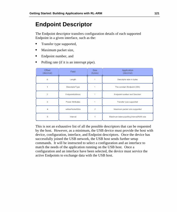
Getting Started: Building Applications with RL-ARM 121
Endpoint Descriptor The Endpoint descriptor transfers configuration details of each supported Endpoint in a given interface, such as the:
Transfer type supported, Maximum packet size, Endpoint number, and Polling rate (if it is an interrupt pipe).
This is not an exhaustive list of all the possible descriptors that can be requested by the host. However, as a minimum, the USB device must provide the host with device, configuration, interface, and Endpoint descriptors. Once the device has successfully joined the USB network, the USB host sends further setup commands. It will be instructed to select a configuration and an interface to match the needs of the application running on the USB host. Once a configuration and an interface have been selected, the device must service the active Endpoints to exchange data with the USB host.
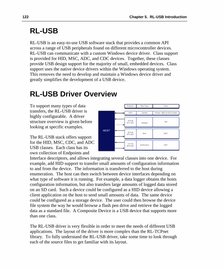
122 Chapter 5. RL-USB Introduction
RL-USB RL-USB is an easy-to-use USB software stack that provides a common API across a range of USB peripherals found on different microcontroller devices. RL-USB can communicate with a custom Windows device driver. Class support is provided for HID, MSC, ADC, and CDC devices. Together, these classes provide USB design support for the majority of small, embedded devices. Class support uses the native device drivers within the Windows operating system. This removes the need to develop and maintain a Windows device driver and greatly simplifies the development of a USB device.
RL-USB Driver Overview To support many types of data transfers, the RL-USB driver is highly configurable. A driver structure overview is given before looking at specific examples.
The RL-USB stack offers support for the HID, MSC, CDC, and ADC USB classes. Each class has its own collection of Endpoints and Interface descriptors, and allows integrating several classes into one device. For example, add HID support to transfer small amounts of configuration information to and from the device. The information is transferred to the host during enumeration. The host can then switch between device interfaces depending on what type of software it is running. For example, a data logger obtains the hosts configuration information, but also transfers large amounts of logged data stored on an SD card. Such a device could be configured as a HID device allowing a client application on the host to send small amounts of data. The same device could be configured as a storage device. The user could then browse the device file system the way he would browse a flash pen drive and retrieve the logged data as a standard file. A Composite Device is a USB device that supports more than one class.
The RL-USB driver is very flexible in order to meet the needs of different USB applications. The layout of the driver is more complex than the RL-TCPnet library. To fully understand the RL-USB driver, take some time to look through each of the source files to get familiar with its layout.

Getting Started: Building Applications with RL-ARM 123
The RL-USB stack is made up of the following files:
usbcfg.h - is a templated configuration file that allows you to enable class support for the Human Interface, Mass Storage, and Audio classes. Is is also used to set the USB configuration and to enable interrupt handlers for the following events:
• Device events: such as start of frame, USB bus reset, USB wakeup.
• Endpoint events: Interrupts raised when an IN or OUT packet is transferred from a given interrupt.
• USB core events: These respond to commands such as set interface sent on the control pipe (Endpoint 0).
usbuser.c - this module contains event handlers for Endpoints 1 – 15. These interrupt handlers allow you to read and write data to the individual endpoint buffers.
usbdesc.c - this module contains the USB descriptors sent to the host during enumeration. These are arrays of data that must mirror the configuration of the RL-USB driver firmware. If you make a mistake here, nothing will work!
usb.h - this file provides an extensive set of #defines for use in the usbdesc.c file. This allows you to construct the descriptors in “natural language” rather than arrays of numbers. This is a huge help in constructing correct descriptors.
usbhw.c - this file provides the necessary low level code for a given USB controller. Normally, you will not need to edit this file.
usbcore.c - this file contains the bulk of the generic RL-USB code. Normally, you will not need to edit this file.
usbhid.c - this is the support file for the HID class. By default, the HID class is configured to transfer one byte IN and OUT packets to the host. The HID class will support a maximum packet size of 64 bytes.
usbmsc.c - this is the support file for the mass storage class. The RL-USB MSC driver links directly to the RL-FlashFS, so normally, you will not need to edit this file.
usbadc.c - this is the support file for the Audio class support. This class transfers data by isochronous packets and you will need to add the necessary code to transfer this data to and from your audio peripherals.
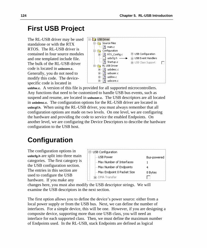
124 Chapter 5. RL-USB Introduction
First USB Project The RL-USB driver may be used standalone or with the RTX RTOS. The RL-USB driver is contained in four source modules and one templated include file. The bulk of the RL-USB driver code is located in usbcore.c. Generally, you do not need to modify this code. The device-specific code is located in usbhw.c. A version of this file is provided for all supported microcontrollers. Any functions that need to be customized to handle USB bus events, such as suspend and resume, are located in usbuser.c. The USB descriptors are all located in usbdesc.c. The configuration options for the RL-USB driver are located in usbcgf.h. When using the RL-USB driver, you must always remember that all configuration options are made on two levels. On one level, we are configuring the hardware and providing the code to service the enabled Endpoints. On another level, we are configuring the Device Descriptors to describe the hardware configuration to the USB host.
Configuration The configuration options in usbcfg.h are split into three main categories. The first category is the USB configuration section. The entries in this section are used to configure the USB hardware. If you make any changes here, you must also modify the USB descriptor strings. We will examine the USB descriptors in the next section.
The first option allows you to define the device’s power source: either from a local power supply or from the USB bus. Next, we can define the number of interfaces. For a simple device, this will be one. However, if you are designing a composite device, supporting more than one USB class, you will need an interface for each supported class. Then, we must define the maximum number of Endpoints used. In the RL-USB, stack Endpoints are defined as logical

Getting Started: Building Applications with RL-ARM 125
Endpoint pairs. Each Endpoint supports an IN and an OUT pipe. Consequently, we define the maximum number of Endpoints as a multiple of 2. The next option allows us to define the maximum packet size for Endpoint 0. The default transfer size on Endpoint 0 is 8 bytes. As we will see later, this can be increased to a maximum of 64 bytes, for faster transfer of data. Finally, if present, the microcontroller DMA unit can be enabled and configured to transfer data to and from selected Endpoint buffers.
#if USB_RESET_EVENT void USB_Reset_Event (void) { USB_ResetCore (); } #endif
Event Handlers The next set of options in usbcfg.h allows us to configure the USB event handlers. We can enable support for USB bus events. Depending on the USB controller, these may be handled by the USB controller hardware or may need additional software support. Each enabled event has a matching function in usbuser.c. The critical functions, such as reset_ event() will be provided, but optional functions, such as start of frame event will be empty stubs, and you will need to provide custom code. There are similar event handlers for each of the enabled Endpoints. Each Endpoint function is responsible for maintaining the IN and OUT buffers for the given Endpoint.
/************************************************** * usbuser.c **************************************************/ void USB_EndPoint1 (DWORD event) { switch (event) { case USB_EVT_IN: GetInReport (); USB_WriteEP (0x81, &InReport, sizeof (InReport)); break; case USB_EVT_OUT: USB_ReadEP (0x01, &OutReport); SetOutReport (); break; } }

126 Chapter 5. RL-USB Introduction
The exception is Endpoint 0. The event handler for Endpoint 0 is located in usbcore.c. As this Endpoint handles the control pipe, it is not necessary to modify this function.
The RL-USB driver also provides some additional call-back functions to handle additional USB control events. These are generally needed for more complex designs of composite devices that have multiple configurations and interfaces.
The set_configuration() and set_interface() functions are triggered when the USB host requests a particular configuration or interface that the device has defined during its enumeration with the USB host. The set_feature() function allows the USB host to send application control information to the device. For example, it might send a volume setting in the case of an audio application.
USB Descriptors Once you have configured the USB hardware, it is also necessary to modify the USB Device Descriptors, so that they match the hardware configuration. The USB Device Descriptors are simply arrays of formatted data. They are contained in the usbdesc.c module. As the USB specification is designed to support a wide range of devices, the USB Device Descriptors can be complex to construct and test. RL-USB provides an additional header file usb.h to assist in the construction of Device Descriptors. This provides a set of macros and type definitions for the key USB Device Descriptors.
In the Device Descriptor, you need to enter your VendorID and ProductID. The Endpoint zero maximum packet size is automatically passed from the usbcfg.h setting. The remaining key descriptors are created as one large array. They are: Configuration Descriptors, Interface Descriptors, and Endpoint Descriptors.
/************************************************** * usbdesc.c **************************************************/ const U8 USB_DeviceDescriptor [] = { … USB_MAX_PACKET0, // bMaxPacketSize0 WBVAL (0xC251), // idVendor WBVAL (0x1701), // idProduct … };

Getting Started: Building Applications with RL-ARM 127
const U8 USB_ConfigDescriptor[] = { … // config descriptor USB_CONFIG_BUS_POWERED // bmAttributes USB_CONFIG_POWER_MA(100), // bMaxPower … // config descriptor continued USB_INTERFACE_DESCRIPTOR_TYPE, // bDescriptorType … // Interface descriptor USB_ENDPOINT_DESCRIPTOR_TYPE, // bDescriptorType … // endpoint descriptor };
In the configuration descriptor, you must define the device as self-powered, USB_CONFIG_SELF_POWERED, or bus-powered USB_CONFIG_BUS_POWERED. If the device is bus-powered, you must also provide its power requirement in mill amperes divided by two. The usbdesc.c module also contains the string descriptors, which are uploaded to the host for display when the device first enumerates.
Each character in the string descriptor is represented as a 16-bit Unicode character and the overall length is the string length plus two.
If you are developing your own device driver for the PC, you can complete the interface and Endpoint descriptors to match your device configuration. This will allow the USB device to enumerate and begin communication with your device driver. However, the RL-USB driver also includes support for standard USB classes. This allows us to take advantage of the native USB driver within Windows. The class support within RL-USB will meet the requirements of 80% - 90% of most small, embedded systems. This route is far easier and faster than developing your own device driver. A vast number of USB-based devices are using these classes. This ensures that the native class device drivers within Windows are very stable and will have guaranteed support and maintenance for the near future.
Class Support The RL-USB driver currently has support for the Human Interface Device (HID), Mass Storage (MSC), Audio Device Class (ADC), and the legacy serial port in the Communications Device Class (CDC). Each of the supported classes can be enabled in the final section of usbcfg.h. Each USB class has a custom C module that must be added to your project.
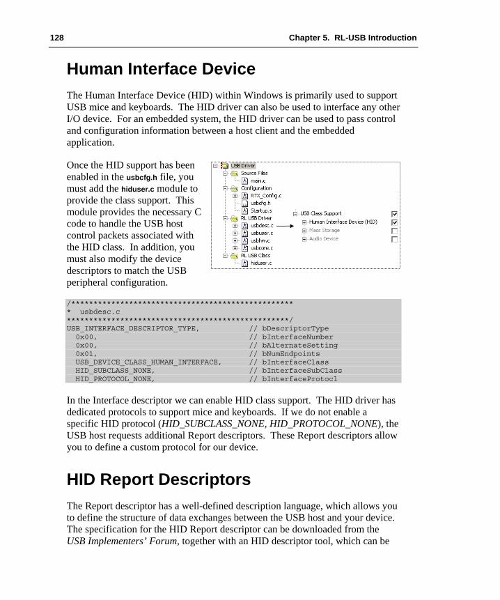
128 Chapter 5. RL-USB Introduction
Human Interface Device The Human Interface Device (HID) within Windows is primarily used to support USB mice and keyboards. The HID driver can also be used to interface any other I/O device. For an embedded system, the HID driver can be used to pass control and configuration information between a host client and the embedded application.
Once the HID support has been enabled in the usbcfg.h file, you must add the hiduser.c module to provide the class support. This module provides the necessary C code to handle the USB host control packets associated with the HID class. In addition, you must also modify the device descriptors to match the USB peripheral configuration.
/************************************************** * usbdesc.c **************************************************/ USB_INTERFACE_DESCRIPTOR_TYPE, // bDescriptorType 0x00, // bInterfaceNumber 0x00, // bAlternateSetting 0x01, // bNumEndpoints USB_DEVICE_CLASS_HUMAN_INTERFACE, // bInterfaceClass HID_SUBCLASS_NONE, // bInterfaceSubClass HID_PROTOCOL_NONE, // bInterfaceProtocl
In the Interface descriptor we can enable HID class support. The HID driver has dedicated protocols to support mice and keyboards. If we do not enable a specific HID protocol (HID_SUBCLASS_NONE, HID_PROTOCOL_NONE), the USB host requests additional Report descriptors. These Report descriptors allow you to define a custom protocol for our device.
HID Report Descriptors The Report descriptor has a well-defined description language, which allows you to define the structure of data exchanges between the USB host and your device. The specification for the HID Report descriptor can be downloaded from the USB Implementers’ Forum, together with an HID descriptor tool, which can be

Getting Started: Building Applications with RL-ARM 129
used to define and test an HID descriptor. Here we examine the basic structure of the HID report descriptor and make modifications to get useful applications. The Report descriptor consists of a series of items. Each item begins with an item TAG that describes the item’s function, scope, and size.
Five main tags define the Report descriptor structure. The first three define the input data structure, output data structure, and configuration features. Another two tags, the collection tag and the end-collection tag, group together the associated input, output, and feature items as shown in the picture. This allows the Windows HID driver to communicate with the USB device.
The simplest devices have one collection that defines the input and output data structures. A more complex device may consist of several such collections. To construct a Report descriptor, we can use the file hid.h. This file contains a series of macros that define the Report descriptor tags. To understand how these are used, we will examine the Report descriptor used in the basic HID example, which may be found in the C:\KEIL\ARM\BOARDS directory.
In this example, the host sends one byte to the device to control the state of eight LEDs. The device then sends one byte to the host. The first three bits report the state of three general purpose input/output (GPIO) pins configured as inputs. The remaining five bits are unused.
HID_UsagePageVendor (0x00), HID_Usage (0x01),
The Report descriptor begins by defining the device’s function through a usage page. The HID specification defines standard application profile pages for common functions. These are defined in the HID usage table document, which can be downloaded from the USB Implementers’ Forum.
130 Chapter 5. RL-USB Introduction
Here, we define a unique vendor profile. The HID Usage is an index pointing to a subset within the usage page. Once the usage table has been defined, open the collection of input and output items. Remember, everything in the USB protocol is host-centric, so data goes IN to the host and OUT from the host to the device.
HID_Collection(HID_Application),
Here, we define a collection of application data. Other types of collections include physical (raw data from a sensor) and logical data (different types of data grouped in a defined format). Remember when writing the HID client to stay consistent at both ends. Next, define the input data structure:
HID_Collection (HID_Application), HID_LogicalMin (0), // data range 0 – 255 HID_LogicalMaxS (0xFF), HID_ReportSize (8), // 8 bits or 1 byte per ‘item’ HID_ReportCount (1), // one ‘item’ or one byte total sizes HID_Usage (0x01), HID_Input (HID_Data | HID_Variable | HID_Absolute),
In the input item, take advantage of the usage pages to describe data as button information. HID_ReportSize() defines the number of bits in each input item. HID_ReportCount() defines the number of items in the report. In this case, we are defining three bits. This also means that the logical minimum and maximum will be zero and one. These values allow us to define a range of expected data values for larger report sizes. The HID input tag defines these three bits as variable data. The HID_absolute value means that the HID driver will not apply any scaling values before it presents the data to the client. Next, define the output item. Again, this is a single byte used to control eight LEDs.
HID_UsagePage (HID_USAGE_PAGE_LED), HID_Usage (HID_USAGE_LED_GENERIC_INDICATOR),
At the beginning of the output item, define the usage page as LED data and describe it as indicator LEDs. Next, define the item format. HID_ReportSize() defines the number of bits in each field. HID_ReportCount() defines the number of data fields. Again, logical minimum and maximum define the range of allowed data values. Finally, define this as output HID data, which will vary over time and no scaling is applied.
HID_LogicalMin(0), HID_LogicalMax(1), HID_ReportCount(8), HID_ReportSize(1), HID_Output(HID_Data | HID_Variable | HID_Absolute),

Getting Started: Building Applications with RL-ARM 131
Once the input and output items have been defined, we can complete the Report descriptor by closing the collection.
HID_EndCollection };
By default, the HID OUT packet is sent to Endpoint 0 as a set_report control packet. Endpoint 0 is normally reserved for control information, but it is the way that the driver works. The IN packet is sent from Endpoint 1. The Endpoint events must be enabled for both of these Endpoints.
The IN packet is configured as an interrupt pipe. Its update rate and maximum packet size are defined in the Endpoint descriptor.
USB_ENDPOINT_DESCRIPTOR_TYPE, // bDescriptorType USB_ENDPOINT_IN(1), // bEndpointAddress USB_ENDPOINT_TYPE_INTERRUPT, // bmAttributes WBVAL(0x0004), // wMaxPacketSize 0x20, // 32ms // bInterval
Once the descriptor configuration is complete, the application code can start the RL-USB driver running.
__task void USB_Start (void) { USB_Init (); // USB Initialization USB_Connect (__TRUE); // USB Connect os_tsk_delete_self (); // Terminate Task }
When the driver has been started, any task can exchange data with the USB host. The USB host will request data packets on Endpoint 1 at the rate you have defined in the Endpoint descriptor. In usbuser.c the Endpoint 1 handler is responsible for updating the Endpoint 1buffer with the current status of the button data.
void USB_EndPoint1 (DWORD event) { switch (event) { case USB_EVT_IN: GetInReport (); USB_WriteEP (0x81, &InReport, sizeof (InReport)); break; } }
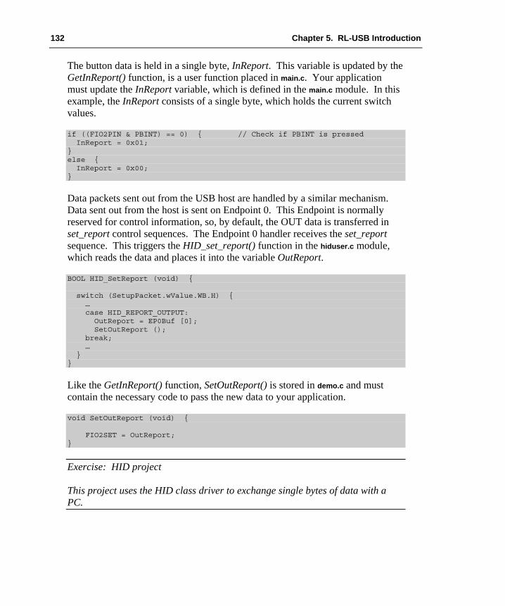
132 Chapter 5. RL-USB Introduction
The button data is held in a single byte, InReport. This variable is updated by the GetInReport() function, is a user function placed in main.c. Your application must update the InReport variable, which is defined in the main.c module. In this example, the InReport consists of a single byte, which holds the current switch values.
if ((FIO2PIN & PBINT) == 0) { // Check if PBINT is pressed InReport = 0x01; } else { InReport = 0x00; }
Data packets sent out from the USB host are handled by a similar mechanism. Data sent out from the host is sent on Endpoint 0. This Endpoint is normally reserved for control information, so, by default, the OUT data is transferred in set_report control sequences. The Endpoint 0 handler receives the set_report sequence. This triggers the HID_set_report() function in the hiduser.c module, which reads the data and places it into the variable OutReport.
BOOL HID_SetReport (void) { switch (SetupPacket.wValue.WB.H) { … case HID_REPORT_OUTPUT: OutReport = EP0Buf [0]; SetOutReport (); break; … } }
Like the GetInReport() function, SetOutReport() is stored in demo.c and must contain the necessary code to pass the new data to your application.
void SetOutReport (void) { FIO2SET = OutReport; }
Exercise: HID project This project uses the HID class driver to exchange single bytes of data with a PC.

Getting Started: Building Applications with RL-ARM 133
HID Client Once the USB firmware has been configured on the microcontroller, it will enumerate with the host. It can then begin to transfer data to and from the Windows HID driver. The next task is to access the relevant HID driver from an application program running on the host. Access to the HID driver is made through Win32 API calls. This can be complicated if you are not used to host programming. However, the source code for a complete HID client application is located in C:\KEIL\ARM\UTILITIES\HID_CLIENT. The client HID can be rebuilt with Visual C++. You will also need the Microsoft Driver Development Kit, which can be downloaded from the Microsoft web site. To make life easy, all of the necessary Win32 API calls have been placed in wrapper functions in the HID.c module. This allows them to be easily reused to build a new custom client.
When a new device is attached to the USB network, it enters the enumeration process with the USB host, identifying itself as an HID device. On a host, this causes the Windows operating system to load a new instance of its HID driver. The HID driver is created with a new Globally Unique Identifier (GUID). This is a 128-bit number identifying the type of object and its access control. When a HID client is started on the host, it can examine the current Windows system for running HID drivers.
HID_Init (); int HID_FindDevices ();
The first two functions are used to initialize the HID client and clear the list of attached devices. Next, the HID_FindDevices() function builds a list of currently connected HID devices and their capabilities. The results of this function call are held in a set of structures. By examining the data held in these structures, you can locate your device from its VendorID and ProductID or other unique feature.
BOOL HID_GetName (int num, char *buf, int sz);
For a more general purpose, the product strings can be read by calling the HID_GetName() function. The product string data can be displayed in the client, allowing the user to make the selection.
BOOL HID_Open (int num);
Once an HID device has been selected, the HID_Open() function is used to connect the client to the HID driver. This is done using the Win32 CreateFile() API call.
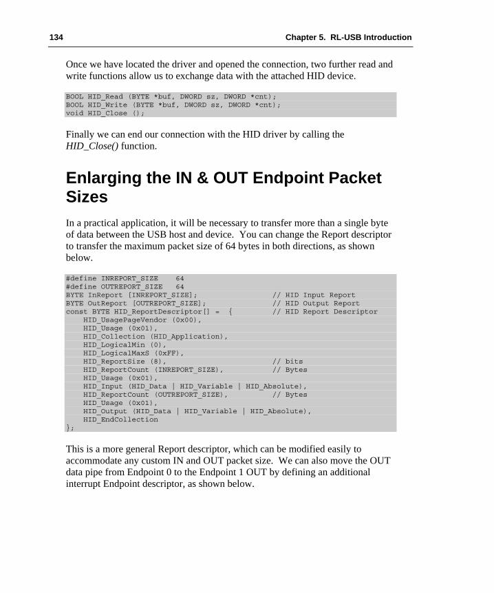
134 Chapter 5. RL-USB Introduction
Once we have located the driver and opened the connection, two further read and write functions allow us to exchange data with the attached HID device.
BOOL HID_Read (BYTE *buf, DWORD sz, DWORD *cnt); BOOL HID_Write (BYTE *buf, DWORD sz, DWORD *cnt); void HID_Close ();
Finally we can end our connection with the HID driver by calling the HID_Close() function.
Enlarging the IN & OUT Endpoint Packet Sizes In a practical application, it will be necessary to transfer more than a single byte of data between the USB host and device. You can change the Report descriptor to transfer the maximum packet size of 64 bytes in both directions, as shown below.
#define INREPORT_SIZE 64 #define OUTREPORT_SIZE 64 BYTE InReport [INREPORT_SIZE]; // HID Input Report BYTE OutReport [OUTREPORT_SIZE]; // HID Output Report const BYTE HID_ReportDescriptor[] = { // HID Report Descriptor HID_UsagePageVendor (0x00), HID_Usage (0x01), HID_Collection (HID_Application), HID_LogicalMin (0), HID_LogicalMaxS (0xFF), HID_ReportSize (8), // bits HID_ReportCount (INREPORT_SIZE), // Bytes HID_Usage (0x01), HID_Input (HID_Data | HID_Variable | HID_Absolute), HID_ReportCount (OUTREPORT_SIZE), // Bytes HID_Usage (0x01), HID_Output (HID_Data | HID_Variable | HID_Absolute), HID_EndCollection };
This is a more general Report descriptor, which can be modified easily to accommodate any custom IN and OUT packet size. We can also move the OUT data pipe from Endpoint 0 to the Endpoint 1 OUT by defining an additional interrupt Endpoint descriptor, as shown below.

Getting Started: Building Applications with RL-ARM 135
// Endpoint, HID Interrupt Out USB_ENDPOINT_DESC_SIZE, // bLength USB_ENDPOINT_DESCRIPTOR_TYPE, // bDescriptorType USB_ENDPOINT_OUT(1), // bEndpointAddress USB_ENDPOINT_TYPE_INTERRUPT, // bmAttributes WBVAL(0x0040), // wMaxPacketSize= 64 0x20,
The Endpoint descriptor is added beneath the existing Endpoint 1 descriptor. We must also make sure that the overall descriptor size reflects the addition of a new Endpoint. This is done within the configuration descriptor as shown below.
USB_CONFIGURATION_DESC_SIZE + USB_INTERFACE_DESC_SIZE + HID_DESC_SIZE + USB_ENDPOINT_DESC_SIZE + // EP1 IN USB_ENDPOINT_DESC_SIZE // New EP1 OUT descriptor
You must also adjust the number of Endpoints defined in the interface descriptor.
USB_INTERFACE_DESCRIPTOR_TYPE, // bDescriptorType 0x00, // bInterfaceNumber 0x00, // bAlternateSetting 0x02, // bNumEndpoints
Once the additional Endpoint is defined, the HID driver will stop sending data as set_report control transfers on Endpoint 0. It will then begin sending OUT packets on Endpoint 1. Now we must add code to receive the new OUT packets on Endpoint 1. Remember that the physical Endpoints are unidirectional, but they are grouped as logical pairs. Each logical Endpoint has a physical IN Endpoint and a physical OUT Endpoint.
void USB_EndPoint1 (DWORD event) { switch (event) { case USB_EVT_IN: GetInReport (); USB_WriteEP (0x81, &InReport, sizeof (InReport)); break; case USB_EVT_OUT: USB_ReadEP (0x01, &OutReport); SetOutReport (); break; } }
This now gives 64 byte IN and OUT packets, which are handled symmetrically on logical Endpoint 1. The SetOutReport() and GetInReport() functions can now be modified to read and write the application data into the new InReport[] and OutReport[] arrays.
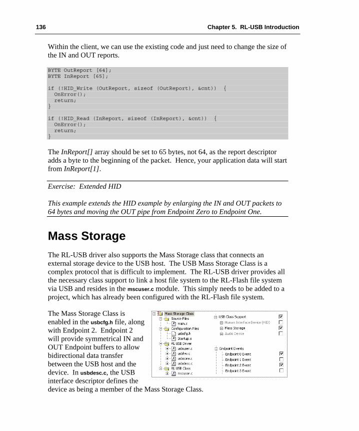
136 Chapter 5. RL-USB Introduction
Within the client, we can use the existing code and just need to change the size of the IN and OUT reports.
BYTE OutReport [64]; BYTE InReport [65]; if (!HID_Write (OutReport, sizeof (OutReport), &cnt)) { OnError(); return; } if (!HID_Read (InReport, sizeof (InReport), &cnt)) { OnError(); return; }
The InReport[] array should be set to 65 bytes, not 64, as the report descriptor adds a byte to the beginning of the packet. Hence, your application data will start from InReport[1].
Exercise: Extended HID This example extends the HID example by enlarging the IN and OUT packets to 64 bytes and moving the OUT pipe from Endpoint Zero to Endpoint One.
Mass Storage The RL-USB driver also supports the Mass Storage class that connects an external storage device to the USB host. The USB Mass Storage Class is a complex protocol that is difficult to implement. The RL-USB driver provides all the necessary class support to link a host file system to the RL-Flash file system via USB and resides in the mscuser.c module. This simply needs to be added to a project, which has already been configured with the RL-Flash file system.
The Mass Storage Class is enabled in the usbcfg.h file, along with Endpoint 2. Endpoint 2 will provide symmetrical IN and OUT Endpoint buffers to allow bidirectional data transfer between the USB host and the device. In usbdesc.c, the USB interface descriptor defines the device as being a member of the Mass Storage Class.

Getting Started: Building Applications with RL-ARM 137
/*---------------------------------------------------------- / Mass storage class interface descriptor ----------------------------------------------------------*/ USB_INTERFACE_DESCRIPTOR_TYPE, // bDescriptorType 0x00, // bInterfaceNumber 0x00, // bAlternateSetting 0x02, // bNumEndpoints USB_DEVICE_CLASS_STORAGE, // bInterfaceClass MSC_SUBCLASS_SCSI, // bInterfaceSubClass MSC_PROTOCOL_BULK_ONLY, // bInterfaceProtocol 0x62, // iInterface
The Mass Storage Class uses pipes, which have been configured to use bulk transfer. Although the bulk transfer type has the lowest priority of the different pipe categories, it does have the advantage of being able to make multiple transfers within a USB frame (if the bandwidth is available). Following interface descriptors are two Endpoint descriptors, which define the IN and OUT Endpoints.
/*---------------------------------------------------------- / Mass storage Endpoint descriptors ----------------------------------------------------------*/ // Bulk In Endpoint USB_ENDPOINT_DESC_SIZE, // bLength USB_ENDPOINT_DESCRIPTOR_TYPE, // bDescriptorType USB_ENDPOINT_IN(2), // bEndpointAddress USB_ENDPOINT_TYPE_BULK, // bmAttributes WBVAL(0x0040), // wMaxPacketSize 0, // bInterval // Bulk Out Endpoint USB_ENDPOINT_DESC_SIZE, // bLength USB_ENDPOINT_DESCRIPTOR_TYPE, // bDescriptorType USB_ENDPOINT_OUT(2), // bEndpointAddress USB_ENDPOINT_TYPE_BULK, // bmAttributes WBVAL(0x0040), // wMaxPacketSize 0, // bInterval // Terminator
The mscuser.c file then provides the application interface to the RL-Flash file system. Once the Mass Storage Class has been added to your application, it will directly interface to the RL-Flash file system and no further development work is necessary to enable it.
However, when your device is connected, the host mass storage driver will take control of the storage volume, and the embedded file system must not be used to read or write data to files located in the storage volume. You must include code to prevent the embedded firmware writing to files, when your device is connected to the host.

138 Chapter 5. RL-USB Introduction
USB_Init(); while (1) { if (WakeUp) { WakeUp = __FALSE; USB_Connect (__FALSE); // USB Disconnect sd_main (); // Call application code } else { if (mmc_init ()) { // Init MSC driver mmc_read_config (&mmcfg); // read card config MSC_BlockCount = mmcfg.blocknr; USB_Connect (__TRUE); // USB Connect } while (!WakeUp); // wait until aplication } // wants file system }
void sd_main (void) { init_card (); while (1) { if (WakeUp) { WakeUp = __FALSE; return; } // add application code here // Set WakeUp to enable USB MSC } }
Exercise: Mass Storage Example This example demonstrates the Mass Storage Class and allows files to be transferred from the PC to the RL-Flash drive using the Windows Explorer.
Audio Class The RL-USB driver also supports an Audio Class Driver. This allows us to stream audio data between the USB host and the device as Isochronous packets. Like the Mass Storage and HID classes, the Audio Class communicates with a standard driver within Windows. Application programs running on the host, which requires an audio input and output, use this driver. The RL-USB driver can be configured to support the Audio Class by adding the adcuser.c class-file to an RL-USB driver project.

Getting Started: Building Applications with RL-ARM 139
In usbcfg.h, the Audio Class support has been enabled, and Endpoint 3 is used for the streaming audio data. As in the HID class configuration, information is sent in the form set_request and get_request control transfers on Endpoint 0. The Device Descriptors are held in usbdesc.c. The descriptors define three interfaces: an Audio Class Control Interface (ADC CIF) and two Audio Class Streaming Interfaces (ADC SIF). One streaming interface is configured as an output and one as an input.
A typical application could use the OUT isochronous pipe to drive a speaker via a Digital-to-Analog Converter (DAC). In the usbuser.c file, the Endpoint 3 callback handler is used to receive the data packet. It transfers data to a buffer using the CPU or DMA unit, if one is available. The Audio Class driver in RL-USB installs a Fast Interrupt Request (FIQ) interrupt. This is used to write the data to the DAC and reproduce the audio stream. The Audio Class also supports feature requests, which are sent on Endpoint 0. These are used to pass control information from the host application to the audio device. In the speaker demonstration, the Audio Control Interface is used to control the volume level and mute function.
Exercise: Audio Class Example This example demonstrates a speaker application using the Audio Class.
Composite Device As we have seen in the previous sections, the RL-USB driver supports three of the most useful USB classes. In some applications, it may be necessary to combine the functionality of two or more classes. For example, you may wish your device to appear as a Mass Storage Device so that you can easily transfer large amounts of data. It may also be useful for the device to appear as a HID device, in order to send small amounts of control and configuration data. RL-USB is designed so that each of the supported classes can be combined into one application to make a composite device.
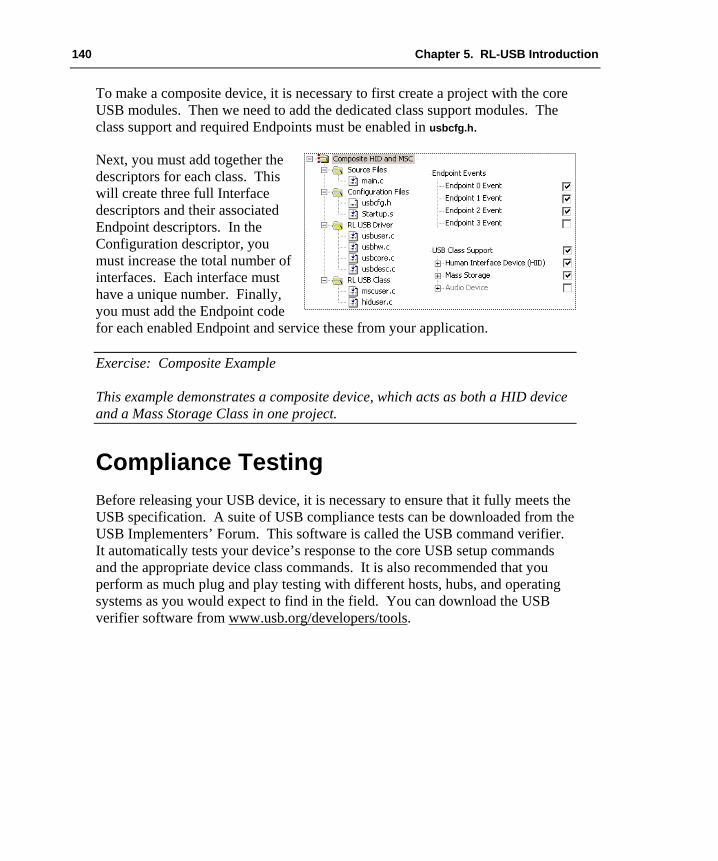
140 Chapter 5. RL-USB Introduction
To make a composite device, it is necessary to first create a project with the core USB modules. Then we need to add the dedicated class support modules. The class support and required Endpoints must be enabled in usbcfg.h.
Next, you must add together the descriptors for each class. This will create three full Interface descriptors and their associated Endpoint descriptors. In the Configuration descriptor, you must increase the total number of interfaces. Each interface must have a unique number. Finally, you must add the Endpoint code for each enabled Endpoint and service these from your application.
Exercise: Composite Example This example demonstrates a composite device, which acts as both a HID device and a Mass Storage Class in one project.
Compliance Testing Before releasing your USB device, it is necessary to ensure that it fully meets the USB specification. A suite of USB compliance tests can be downloaded from the USB Implementers’ Forum. This software is called the USB command verifier. It automatically tests your device’s response to the core USB setup commands and the appropriate device class commands. It is also recommended that you perform as much plug and play testing with different hosts, hubs, and operating systems as you would expect to find in the field. You can download the USB verifier software from www.usb.org/developers/tools.

Getting Started: Building Applications with RL-ARM 141
Chapter 6. RL-CAN Introduction The CAN (Controller Area Network) protocol was originally developed for networking in the automotive sector. The aim was to replace the wiring loom in passenger vehicles. CAN is characterized by relatively fast data transfer, good error detection, good recovery and low electromagnetic interference (EMI). Unlike Ethernet, its arbitration method can guarantee deterministic delivery of message packets within defined system latency. It has been widely adopted into many industries as a de-facto standard for distributed control systems, as it is an ideal method of networking small, embedded systems. This chapter examines the RL-CAN driver, which allows you to rapidly and easily build a CAN network with many different manufacturers’ CAN controller peripherals.
The CAN Protocol – Key Concepts In the ISO 7-layer model, the CAN protocol covers the layer two, ”Data Link Layer”. This involves forming the message packet, error containment, acknowledgement, and arbitration.
CAN does not rigidly define layer one “Physical Layer”. This means, that CAN messages may use many different physical mediums. However, the most common physical layer is a twisted pair, and standard line drivers are available for it. In a CAN network, the other layers in the ISO model are effectively empty, and your application code will communicate directly to the data link layer.
The application code addresses the registers of the CAN peripheral directly. In effect, the CAN peripheral can be used as a glorified UART, without the need for an expensive and complex protocol stack. Since CAN is also used in Industrial Automation, there are a number of software standards defining how the CAN messages are used. This is necessary in order to transfer data between different manufacturers’ equipment.

142 Chapter 6. RL-CAN Introduction
The two most popular of these application layer standards are CANopen and DeviceNet. The sole purpose of these standards is to provide interoperability between different Original Equipment Manufacturers’ (OEM) equipment. If you are developing your own closed system, then you do not need these application layer protocols. You are free to implement your own proprietary protocol, which many developers do.
CAN Node Design A typical CAN node is shown in the picture. Each node consists of a microcontroller and a CAN controller. The CAN controller may be fabricated on the same silicon as the microcontroller. Alternatively, it may be a standalone controller in a separate chip from the microcontroller. The CAN controller is interfaced to the twisted pair by a CAN Transceiver. The twisted pair is terminated at either end by a 120 Ohm resistor. The most common mistake with a first CAN network is to forget the terminating resistors and then nothing works.
The CAN controller has separate transmit and receive paths to and from the Physical Layer device. This is an important feature of the CAN node. Therefore, as the node is writing to the bus, it is also listening back. This is the basis of the message arbitration and it also contributes to the error detection. The two logic levels, which are written on to the twisted pair, are defined as follows; a logic one is represented by bus idle, with both wires held half way between 0 and VCC. A logic zero is represented by both wires being differentially driven.

Getting Started: Building Applications with RL-ARM 143
On the CAN bus, logic zero is represented by a maximum voltage difference called “Dominant.” Logic one (1) is represented by a bus idle state called “Recessive”. A dominant bit will overwrite a recessive bit. Therefore, if ten nodes write recessive and one writes dominant, then each node will read back a dominant bit. The CAN bus can achieve bit rates of up to a maximum of 1Mb/s. Typically, this can be achieved over 40 meters of cable. Longer cable lengths can be achieved by reducing the bit rate. In practice, you can get at least 1,500 meters with the standard drivers at 10 Kbit/s.
CAN Message Frames The CAN bus has two message objects, which may be generated by the application software. These are the message frame and the remote request frame. The message frame is used to transfer data around the network. The message frame is shown below.
The CAN controller forms the message frame. The application software provides the data bytes, the message identifier, and the RTR bit.
The message frame starts with a dominant bit to mark the start of frame. Next is the message identifier, which may be up to 29 bits long. The message identifier is used to label the data being sent in the message frame. CAN is a producer/consumer protocol or broadcast protocol. A given message is produced from one unique node and then may be consumed by any number of nodes on the network simultaneously. It is also possible to do point-to-point communication by making only one node interested in a given identifier. Then a message can be sent from the producer node to one given consumer node on the network. In the message frame, the RTR bit is always set to zero (this field will be discussed shortly). The Data Length Code (DLC) field contains an integer between zero and eight, and indicates the number of data bytes being sent in this message frame. You can send a maximum of 8 bytes in the message payload. It is also possible to truncate the message frame to save bandwidth on the CAN bus. After the 8 bytes of data, there is a 15-bit Cyclic Redundancy Check (CRC). This
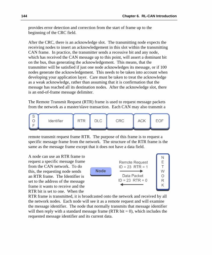
144 Chapter 6. RL-CAN Introduction
provides error detection and correction from the start of frame up to the beginning of the CRC field.
After the CRC, there is an acknowledge slot. The transmitting node expects the receiving nodes to insert an acknowledgement in this slot within the transmitting CAN frame. In practice, the transmitter sends a recessive bit and any node, which has received the CAN message up to this point, will assert a dominant bit on the bus, thus generating the acknowledgement. This means, that the transmitter will be satisfied if just one node acknowledges its message, or if 100 nodes generate the acknowledgement. This needs to be taken into account when developing your application layer. Care must be taken to treat the acknowledge as a weak acknowledge, rather than assuming that it is confirmation that the message has reached all its destination nodes. After the acknowledge slot, there is an end-of-frame message delimiter.
The Remote Transmit Request (RTR) frame is used to request message packets from the network as a master/slave transaction. Each CAN may also transmit a
remote transmit request frame RTR. The purpose of this frame is to request a specific message frame from the network. The structure of the RTR frame is the same as the message frame except that it does not have a data field.
A node can use an RTR frame to request a specific message frame from the CAN network. To do this, the requesting node sends an RTR frame. The Identifier is set to the address of the message frame it wants to receive and the RTR bit is set to one. When the RTR frame is transmitted, it is broadcasted onto the network and received by all the network nodes. Each node will see it as a remote request and will examine the message identifier. The node that normally transmits that message identifier will then reply with a standard message frame (RTR bit = 0), which includes the requested message identifier and its current data.

Getting Started: Building Applications with RL-ARM 145
As previously mentioned, the CAN message identifier can be up to 29 bits long. There are two standards of CAN protocol, the only difference being the length of the message identifier.
It is possible to mix the two protocol standards on the same bus, but you must not send a 29-bit message to a 2.0A device.
CAN Bus Arbitration If a message is scheduled to be transmitted on to the bus and the bus is idle, it will be transmitted and may be picked up by any interested node. If a message is scheduled and the bus is active, it will have to wait until the bus is idle, before it can be transmitted. If several messages are scheduled while the bus is active, they will start transmission simultaneously once the bus becomes idle, being synchronized by the start of frame bit. When this happens, the CAN bus arbitration will take place to determine which message wins the bus and is transmitted.

146 Chapter 6. RL-CAN Introduction
CAN arbitrates its messages by a method called “non-destructive bit-wise arbitration”. In the diagram, three messages are pending transmission. Once the bus is idle and the messages are synchronized by the start bit, they will start to write their identifiers on to the bus. For the first two bits, all three messages write the same logic and, hence, read back the same logic, so each node continues transmission. However, on the third bit, nodes A and C write dominant bits, and node B writes recessive. At this point, node B wrote recessive but reads back dominant. In this case, it will back off the bus and start listening.
Nodes A and C will continue transmission until node C writes recessive and node A writes dominant. Now, node C stops transmission and starts listening. Node A has won the bus and will send its message. Once node A has finished, the nodes B and C will transmit. Node C will win and send its message. Finally, node B will send its message. If node A is scheduled again, it will win the bus even though the node B and C messages have been waiting. In practice, the CAN bus will transmit the message with the lowest value identifier first.
RL-CAN Driver As mentioned above, CAN has been widely adopted for distributed control within embedded systems. Today, just about all microcontroller families include a variant, or variants, with a CAN controller peripheral. However, each manufacturer’s CAN controller has a different set of special function registers and features. The RL-ARM library includes a dedicated CAN driver, which provides a standard programming API for all supported microcontrollers. The CAN driver uses RTX message queues to buffer data before it is transmitted or received. The RL-CAN driver provides a quick and easy way to implement a CAN network. The RL-CAN driver also provides code portability, in case you need migrating code to another microcontroller.
First Project Unlike the other middleware components within the RL-ARM library, the RL-CAN driver must be used with RTX.
The RL-CAN driver consists of two C modules and associated header files. The first module, RTX_CAN.c, is a generic layer driver, which provides the high
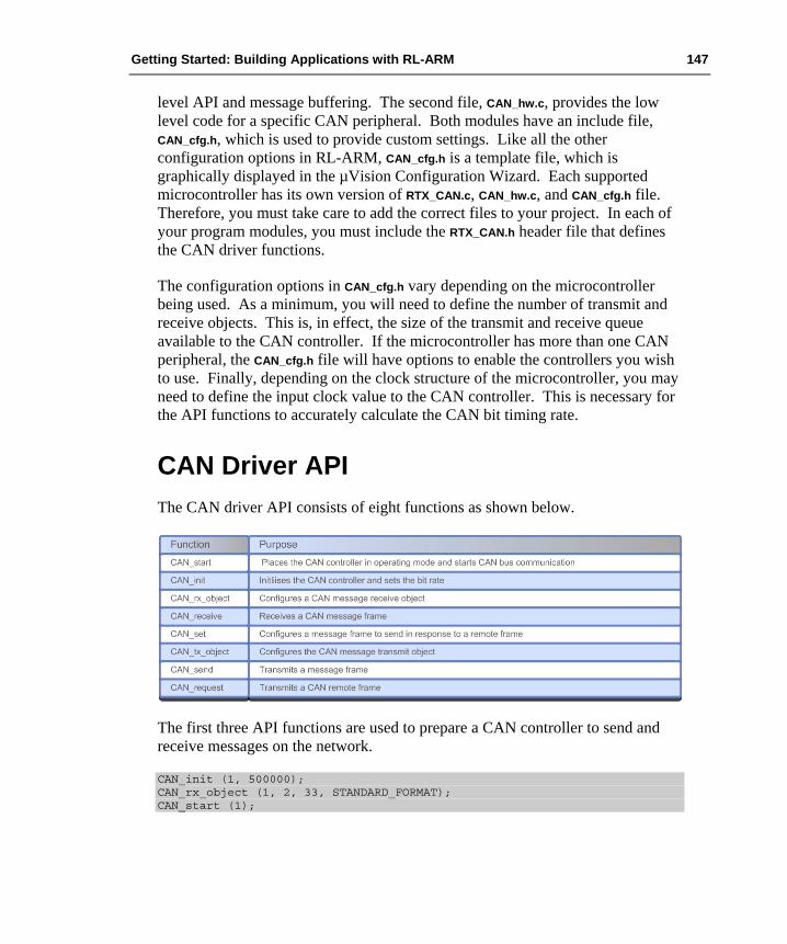
Getting Started: Building Applications with RL-ARM 147
level API and message buffering. The second file, CAN_hw.c, provides the low level code for a specific CAN peripheral. Both modules have an include file, CAN_cfg.h, which is used to provide custom settings. Like all the other configuration options in RL-ARM, CAN_cfg.h is a template file, which is graphically displayed in the µVision Configuration Wizard. Each supported microcontroller has its own version of RTX_CAN.c, CAN_hw.c, and CAN_cfg.h file. Therefore, you must take care to add the correct files to your project. In each of your program modules, you must include the RTX_CAN.h header file that defines the CAN driver functions.
The configuration options in CAN_cfg.h vary depending on the microcontroller being used. As a minimum, you will need to define the number of transmit and receive objects. This is, in effect, the size of the transmit and receive queue available to the CAN controller. If the microcontroller has more than one CAN peripheral, the CAN_cfg.h file will have options to enable the controllers you wish to use. Finally, depending on the clock structure of the microcontroller, you may need to define the input clock value to the CAN controller. This is necessary for the API functions to accurately calculate the CAN bit timing rate.
CAN Driver API The CAN driver API consists of eight functions as shown below.
The first three API functions are used to prepare a CAN controller to send and receive messages on the network.
CAN_init (1, 500000); CAN_rx_object (1, 2, 33, STANDARD_FORMAT); CAN_start (1);

148 Chapter 6. RL-CAN Introduction
CAN_init() defines the bit rate of a given CAN controller. The CAN driver supports microcontrollers with multiple CAN controllers. Each CAN controller is referred to by a number that starts from one. These numbers map directly onto the physical CAN controllers on the microcontroller in ascending order. Here, CAN controller 1 runs at 500K bit/sec. Next, the CAN_rx_object() function is used to define which message identifiers will be received into the selected CAN controller. In the above example, we have selected CAN controller 1 to receive message ID 33. The second parameter in the CAN_rx_object() function refers to the message channel. We will look at this in the object buffer section later in this chapter. You may also define whether the message ID is 11-bit (standard) or 29-bit (extended) in length. The CAN controller will only receive messages that have been defined with the CAN_rx_object() function. Once we have defined all of the messages that we want to receive, the CAN controller must be placed in its running mode by calling the CAN_start() function.
Basic Transmit and Receive Once the CAN controller has entered running mode it is possible to send and receive messages to and from the CAN network. The CAN message format is held in a structure defined in CAN_cfg.h.
typedef struct { U32 id; // message identifier U8 data [8]; // Message data payload U8 len; // Number of bytes in the message payload U8 ch; // CAN controller channel U8 format; // Standard (11-bit) ID or extended (29-bit) ID U8 type; // Data frame or remote request frame } CAN_msg;
To send a message define the CAN message structure. This structure reflects the fields of the CAN message frame. In the example below, a message frame msg_send is defined with an identifier of 33, followed by eight bytes of user-defined data. The data length code is set to one, so that only the first data byte will be transmitted. The message will be sent through channel 1. The frame will start with an 11-bit identifier followed by a message frame.
CAN_msg msg_send = { 33, {0x00, 0x00, 0x00, 0x00, 0x00, 0x00, 0x00, 0x00}, 1, 2, STANDARD_FORMAT, DATA_FRAME };

Getting Started: Building Applications with RL-ARM 149
Then we call the CAN send function:
CAN_send (1, &msg_send, 0x0F00);
This will place the CAN message into the message queue. The message queue is a First-In-First-Out (FIFO) buffer, so the messages are guaranteed to be sent in order. The “number of transmit objects” in CAN_cfg.h defines the depth of the FIFO buffer in message frames. If the FIFO becomes full, the CAN send function will wait for its timeout period for a message slot to become free. As with other RTX functions, this will cause the task to enter the WAITING state, so that the next task in the READY state enter the RUN state.
if (CAN_receive (1, &msg_rece, 0x00FF) == CAN_OK) { Rx_val = msg_rece.data [0]; }
The CAN Receive function operates in a similar fashion. As messages are received, they are placed into the receive-object FIFO. The CAN Receive function is then used to access message frames in the FIFO. If the FIFO is empty, the timeout period specifies the number of RTX clock ticks CAN_receive() will wait for a message to arrive.
Exercise: First Project The first RL-CAN driver project guides you through setting up the RL-CAN driver to transmit and receive CAN messages.
Remote Request The RL-CAN driver may also send and respond to remote request frames. First, you must define the message frame as a remote request.
CAN_msg msg_rmt = { 21, {0x00, 0x00, 0x00, 0x00, 0x00, 0x00, 0x00, 0x00}, 1, 2, STANDARD_FORMAT, REMOTE_FRAME };
When this message is sent, the message frame contains no data and the remote request bit is set. When this frame is sent, every node on the network will receive it. Each node will inspect the message identifier.

150 Chapter 6. RL-CAN Introduction
The node that sends this message will immediately reply to the remote frame with a message frame matching the identifier and its current data.
When sending the remote frame you must be careful with the DLC setting. Although the remote frame does not contain any data, the DLC should not be set to zero. Rather, it should be set to the length of the data packet in the reply message frame.
Once the remote frame has been defined, we can use it to request a message frame from the network.
CAN_request (1,&msg_rmt, 0xFFFF);
All nodes on the network will receive the remote frame. The node that sends message frames for the requested ID will then send a reply data frame with the requested ID and its current data. The RL_CAN driver contains a CAN_set() function, which allows a CAN node to respond automatically to a remote request. First, you must define a CAN message frame in the same way as for the CAN_send() function.
CAN_msg msg_for_remote = { 21, {0x01, 0x02, 0x00, 0x00, 0x00, 0x00, 0x00, 0x00}, 1, 2, STANDARD_FORMAT, DATA_FRAME };
The message frame is then passed to the CAN_set() function.
CAN_set (1, &msg_for_remote, 0x00ff);
This message frame will now be transmitted when a remote request with a matching ID is received.
Exercise: Remote Request This exercise configures a message object to send a remote frame and prepares another to reply.
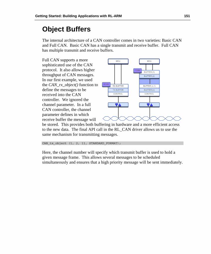
Getting Started: Building Applications with RL-ARM 151
Object Buffers The internal architecture of a CAN controller comes in two varieties: Basic CAN and Full CAN. Basic CAN has a single transmit and receive buffer. Full CAN has multiple transmit and receive buffers.
Full CAN supports a more sophisticated use of the CAN protocol. It also allows higher throughput of CAN messages. In our first example, we used the CAN_rx_object() function to define the messages to be received into the CAN controller. We ignored the channel parameter. In a full CAN controller, the channel parameter defines in which receive buffer the message will be stored. This provides both buffering in hardware and a more efficient access to the new data. The final API call in the RL_CAN driver allows us to use the same mechanism for transmitting messages.
CAN_tx_object (1, 2, 11, STANDARD_FORMAT);
Here, the channel number will specify which transmit buffer is used to hold a given message frame. This allows several messages to be scheduled simultaneously and ensures that a high priority message will be sent immediately.

152 Glossary
Glossary AJAX Asynchronous JavaScript and XML A group of client side technologies designed to create rich internet applications.
ARP Address Resolution Protocol On a LAN, ARP is used to discover a stations MAC address when only its IP address is known.
ADC Audio Device Class A USB class designed to allow bi directional transfer of Audio data between A USB host and device.
CAN Controller Area Network A bus standard designed specifically for automotive applications. Meanwhile also used in other industries. It allows microcontrollers and devices to communicate with each other without a host computer.
CGI Common Gateway Interface A standard protocol for interfacing application software to an internet service typically a HTTP server.
Composite A USB device that supports two or more device classes.
Co-operative A form of operating system scheduling. Each task must de schedule itself to allow other tasks to run.
CRC Cyclic Redundancy Check A type of function to detect accidental alternation of data during storage or transmission.
Getting Started: Building Applications with RL-ARM 153
Datagram A networking message packet that does not provide any form of delivery acknowledgment.
DHCP Dynamic Host Control Protocol A TCP\IP networking protocol that allows a station to obtain configuration information.
DLC Data Length Code Indicates how many data bytes are in a CAN message packet. CAN messages are of variable length. The DLC can be from 0 to 8 bytes long.
DNS Domain Name System A Hierarchical naming system for the internet that translates names, such as www.example.com to an IP address such as 207.183.123.442.
Ethernet A frame based computer networking technology for Local Area Networks.
FIFO First In, First Out Expresses how data are organized and manipulated relative to time and prioritization. It describes the working principle of a queue. What comes in first is handled first, what comes in next waits until the first is finished, etc.
Flash File System A computer file system designed for small solid-state devices, typically NAND FLASH memory.
FTP File Transfer Protocol An internet protocol designed to transfer files between a client and a remote internet station.

154 Glossary
HID Human Interface Device A USB device class that supports peripherals, which provide input and output to humans. Typically, these are mouse and keyboards.
HTTP Hyper Text Transfer Protocol A TCP\IP application level protocol for distributed “hypertext”. A collection of inter-linked resources that forms the world wide web.
Hub A USB Hub connects to a single USB port and provides additional connection ports for USB devices or further hubs.
ICMP Internet Control Message Protocol A TCP\IP protocol used to provide error, diagnostic and routing information between TCP\IP stations.
IP Internet Protocol The primary protocol in the TCP\IP networking suite. IP delivers protocol datagrams between source and destination stations based solely on their addresses.
Mailbox A region of memory that is used to queue formatted messages passed between operating system tasks.
MAC Media Access Control A unique identifier assigned to the Ethernet network adapter.
MSD Mass Storage Device A USB device class that supports interfacing of an external storage device to a USB host.
Mutex A form of binary semaphore that is used to ensure exclusive access to a common resource or critical section of code in a real-time operating system.

Getting Started: Building Applications with RL-ARM 155
Port A communication endpoint with an internet station. Used by TCP and UDP to pass a data payload to a specific application protocol.
PPP Point-to-Point Protocol An internet protocol designed to provide a TCP\IP connection over a serial or modem link.
Pre-Emptive A form of priority based scheduling in a Real-Time Operating System. The highest priority task ready to run will be scheduled until it blocks or a higher priority task is ready to run.
TCP Transmission Control Protocol A primary protocol in the TCP\IP networking suite. TCP provides a reliable ordered delivery of data from one TCP\IP station to another.
UDP User Datagram Protocol A primary protocol in the TCP\IP networking suite. UPD provides a simple transmission model without handshaking. UDP provides an ‘unreliable’ service; the application software must provide error checking and handshaking if necessary.
RTR Remote Transmission Request Also part of the CAN message frame to differentiate a data frame from a remote frame. The dominant RTR bit (set to 0) indicates a data frame; where as a recessive RTR-bit (set to 1) indicates a remote request frame.
Round Robin A form of scheduling in a real-time operating system where each task is allotted a fixed amount of run time on the CPU.
Semaphore A semaphore is an abstract data type used to control access to system resources in a real-time operating system.

156 Glossary
SLIP Serial Line Internet Protocol An internet protocol designed to provide a TCP\IP connection over a serial or modem link. SLIP is now obsolete and is replaced by PPP.
SMTP Simple Mail Transfer Protocol A TCP\IP application layer protocol for electronic mail transfer. SMTP is used by a client to send email by connecting to a remote server.
TFTP Trivial File Transfer protocol TFTP is a minimal file transfer protocol originally designed to boot internet stations that did not have any form of data storage.
Telnet Telnet is an internet protocol that provides a command line interface between a client and a remote internet station.
USB Universal Serial Bus A serial bus designed to allow easy plug and play expansion for PCs.
Task In an operating system, a task is a self-contained unit of code. Generally used in real-time computing.
SD/MMC Secure Digital/Multi Media Card Non volatile memory card formats used for portable devices.