gerard o’regan introduction to software qualitysebastiao/ensino/ubi/2017... · the first chapter...
TRANSCRIPT

Undergraduate Topics in Computer Science
Gerard O’Regan
Introduction to Software Quality

Undergraduate Topics in Computer Science

Undergraduate Topics in Computer Science (UTiCS) delivers high-quality
instructional content for undergraduates studying in all areas of computing and
information science. From core foundational and theoretical material to final-year
topics and applications, UTiCS books take a fresh, concise, and modern approach
and are ideal for self-study or for a one- or two-semester course. The texts are all
authored by established experts in their fields, reviewed by an international
advisory board, and contain numerous examples and problems. Many include fully
worked solutions.
For further volumes:http://www.springer.com/series/7592

Gerard O’Regan
Introduction to SoftwareQuality

Gerard O’ReganSQC ConsultingMallow, Cork, Ireland
ISSN 1863-7310 ISSN 2197-1781 (electronic)ISBN 978-3-319-06105-4 ISBN 978-3-319-06106-1 (eBook)DOI 10.1007/978-3-319-06106-1Springer Cham Heidelberg New York Dordrecht London
Library of Congress Control Number: 2014936841
# Springer International Publishing Switzerland 2014This work is subject to copyright. All rights are reserved by the Publisher, whether the whole or partof the material is concerned, specifically the rights of translation, reprinting, reuse of illustrations,recitation, broadcasting, reproduction on microfilms or in any other physical way, and transmission orinformation storage and retrieval, electronic adaptation, computer software, or by similar or dissimilarmethodology now known or hereafter developed. Exempted from this legal reservation are brief excerptsin connection with reviews or scholarly analysis or material supplied specifically for the purpose of beingentered and executed on a computer system, for exclusive use by the purchaser of the work. Duplicationof this publication or parts thereof is permitted only under the provisions of the Copyright Law of thePublisher’s location, in its current version, and permission for use must always be obtained fromSpringer. Permissions for use may be obtained through RightsLink at the Copyright Clearance Center.Violations are liable to prosecution under the respective Copyright Law.The use of general descriptive names, registered names, trademarks, service marks, etc. in thispublication does not imply, even in the absence of a specific statement, that such names are exemptfrom the relevant protective laws and regulations and therefore free for general use.While the advice and information in this book are believed to be true and accurate at the date ofpublication, neither the authors nor the editors nor the publisher can accept any legal responsibility forany errors or omissions that may be made. The publisher makes no warranty, express or implied, withrespect to the material contained herein.
Printed on acid-free paper
Springer is part of Springer Science+Business Media (www.springer.com)
Series EditorIan Mackie
Advisory BoardSamson Abramsky, University of Oxford, Oxford, UK
Karin Breitman, Pontifical Catholic University of Rio de Janeiro, Rio de Janeiro, Brazil
Chris Hankin, Imperial College London, London, UK
Dexter Kozen, Cornell University, Ithaca, USA
Andrew Pitts, University of Cambridge, Cambridge, UK
Hanne Riis Nielson, Technical University of Denmark, Kongens Lyngby, Denmark
Steven Skiena, Stony Brook University, Stony Brook, USA
Iain Stewart, University of Durham, Durham, UK

ToKevin and Maura and the four princesses(Eve, Grace, Jane and Tara)


Preface
Overview
The objective of this book is to provide an introduction to the software quality field
to students and practitioners, and it is based on the author’s experience in software
quality and software process improvement at leading industrial companies. The
principles of software quality management and software process improvement
are discussed.
The goal is to cover both theory and practice, and to give the reader a grasp
of the fundamentals of the software quality field, as well as guidance on how to
apply the theory in an industrial environment.
Organization and Features
The first chapter provides an introduction to the fundamentals of the quality
management field, and provides historical background on several pioneers such
as Deming, Juran, and Crosby.
Chapter 2 provides a broad overview of software engineering and discusses
various software lifecycles and the phases in software development. It includes a
discussion on requirements elicitation, software design, implementation, testing,
and maintenance.
Chapter 3 provides an introduction to project management and discusses project
estimation, project planning and scheduling, project monitoring and control, risk
management, and managing project quality.
Chapter 4 discusses requirements and design and is concerned with requirements
engineering and management, architectural design, and design and development.
Chapter 5 discusses configuration management and discusses the fundamental
concept of a baseline. Configuration management is concerned with identifying
those deliverables that must be subject to change control, and controlling changes
to them.
Chapter 6 discusses software inspections which play a key role in building
quality into a product. The well-known Fagan inspection process which was
developed at IBM in the 1970s is discussed, as well as lighter review and walk-
through methodologies.
vii

Chapter 7 is concerned with software testing and discusses the various types of
testing that may be carried out. It includes a discussion on test planning, test case
definition, test tracking, test metrics, test reporting, and testing in an e-commerce
environment.
Chapter 8 is concerned with the selection and management of a software
supplier. It discusses how candidate suppliers may be formally evaluated, and
how the selected supplier may be managed during the project.
Chapter 9 nine discusses software quality assurance and the importance of
process quality. It is a premise in the quality field that conformance to the defined
process is essential in the delivery of high-quality product, and this chapter
discusses audits, and describes how they are carried out.
Chapter 10 is concerned with metrics and problem solving, and this includes a
discussion of the balanced score card which assists in identifying appropriate
metrics for the organization. The Goal, Question, Metrics (GQM) approach is
discussed, and this is useful in defining metrics that are related to the organization
goals. This chapter includes a collection of sample metrics for an organization.
Problem solving tools such as fishbone diagrams, pareto charts, and trend charts are
also discussed.
Chapter 11 discusses the ISO 9000 standard, which is an important standard for
product and service delivery. This family of standards includes ISO 9001 and ISO
9004. The main features of the standard are discussed as well as guidance on its
implementation.
Chapter 12 discusses software process improvement. It begins with a discussion
of a software process, and discusses the benefits that may be gained from a software
process improvement initiative. Various models that support software process
improvement are discussed, and these include the CMMI, ISO 9000, PSP, and TSP.
Chapter 13 gives an overview of the CMMI model and discusses its five maturity
levels and their constituent process areas. It includes a discussion of both the staged
and continuous representations.
Chapter 14 describes the activities and teams required to set up a CMMI
improvement initiative for an organization. These include the CMMI Steering
Group, the SEPG team, and process specific teams.
Chapter 15 discusses the SCAMPI appraisal methodology. This includes the
formal SCAMPI Class A appraisal often employed by large organizations to obtain
a CMMI rating that allows them to benchmark themselves against other
organizations, and SCAMPI Class B and C appraisals that are less expensive and
time consuming but may not be used for benchmarking.
Chapter 16 discusses various tools to support the organizations in the various
software engineering activities. The focus is first to define the process, and then to
find tools to support the process. Tools to support project management are discussed
as well as tools to support requirements engineering, configuration management,
design and development activities, and software testing.
Chapter 17 discusses formal methods, which consist of a set of mathematical
techniques to specify and derive a program from its specification. Formal methods
may be employed to rigorously state the requirements of the proposed system; they
viii Preface

may be employed to derive a program from its mathematical specification; and they
provide a rigorous proof that the implemented program satisfies its specification.
They have been mainly applied to the safety critical field.
Chapter 18 presents the Z specification language, which is one of the most
widely used formal methods. It was developed at Oxford University in the UK.
Chapter 19 presents the unified modelling language (UML) which is used to
present several views of the system architecture. Chapter 20 is the concluding
chapter in which we summarize the journey that we have travelled in this book.
Audience
The main audience of this book are computer science students who are interested in
learning about software quality, and in learning on how to build high-quality and
reliable software on time and on budget. It will also be of interest to industrialists
including software engineers, quality professionals, and software managers as well
as the motivated general reader.
Mallow, Cork, Ireland Gerard O’Regan
Preface ix


Acknowledgments
I am deeply indebted to family and friends who supported my efforts in this
endeavour.
xi


Contents
1 Introduction . . . . . . . . . . . . . . . . . . . . . . . . . . . . . . . . . . . . . . . . . . 1
1.1 Introduction . . . . . . . . . . . . . . . . . . . . . . . . . . . . . . . . . . . . . 1
1.1.1 The Software Engineering Challenge . . . . . . . . . . . . 2
1.2 History of Software Failures . . . . . . . . . . . . . . . . . . . . . . . . . 4
1.3 Background to Software Quality . . . . . . . . . . . . . . . . . . . . . . 5
1.3.1 What Is Software Quality? . . . . . . . . . . . . . . . . . . . 5
1.3.2 Early Quality Management . . . . . . . . . . . . . . . . . . . 6
1.3.3 Total Quality Management . . . . . . . . . . . . . . . . . . . 6
1.3.4 Software Quality Control . . . . . . . . . . . . . . . . . . . . 7
1.4 History of Quality . . . . . . . . . . . . . . . . . . . . . . . . . . . . . . . . . 8
1.4.1 Shewhart . . . . . . . . . . . . . . . . . . . . . . . . . . . . . . . . 8
1.4.2 Deming . . . . . . . . . . . . . . . . . . . . . . . . . . . . . . . . . 10
1.4.3 Juran . . . . . . . . . . . . . . . . . . . . . . . . . . . . . . . . . . . 12
1.4.4 Crosby . . . . . . . . . . . . . . . . . . . . . . . . . . . . . . . . . . 15
1.4.5 Watts Humphrey . . . . . . . . . . . . . . . . . . . . . . . . . . 17
1.4.6 Miscellaneous Quality Gurus . . . . . . . . . . . . . . . . . 19
1.5 Modern Software Quality Management . . . . . . . . . . . . . . . . . 20
1.5.1 Software Inspections . . . . . . . . . . . . . . . . . . . . . . . 20
1.5.2 Software Testing . . . . . . . . . . . . . . . . . . . . . . . . . . 21
1.5.3 Software Quality Assurance . . . . . . . . . . . . . . . . . . 21
1.5.4 Problem Solving Techniques . . . . . . . . . . . . . . . . . . 22
1.5.5 Cost of Quality . . . . . . . . . . . . . . . . . . . . . . . . . . . . 24
1.5.6 Software Process Improvement . . . . . . . . . . . . . . . . 25
1.5.7 Software Metrics . . . . . . . . . . . . . . . . . . . . . . . . . . 26
1.5.8 Customer Satisfaction . . . . . . . . . . . . . . . . . . . . . . . 26
1.5.9 Assessments (Appraisals) . . . . . . . . . . . . . . . . . . . . 29
1.5.10 Total Quality Management . . . . . . . . . . . . . . . . . . . 29
1.6 Miscellaneous . . . . . . . . . . . . . . . . . . . . . . . . . . . . . . . . . . . . 30
1.6.1 Organization Culture and Change . . . . . . . . . . . . . . 30
1.6.2 Law of Negligence . . . . . . . . . . . . . . . . . . . . . . . . . 31
1.6.3 Quality and the WEB . . . . . . . . . . . . . . . . . . . . . . . 31
1.7 Review Questions . . . . . . . . . . . . . . . . . . . . . . . . . . . . . . . . . 32
1.8 Summary . . . . . . . . . . . . . . . . . . . . . . . . . . . . . . . . . . . . . . . 32
xiii
2 Software Engineering . . . . . . . . . . . . . . . . . . . . . . . . . . . . . . . . . . . 35
2.1 Introduction . . . . . . . . . . . . . . . . . . . . . . . . . . . . . . . . . . . . . 35
2.2 What Is Software Engineering? . . . . . . . . . . . . . . . . . . . . . . . 38
2.3 Challenges in Software Engineering . . . . . . . . . . . . . . . . . . . . 40
2.4 Software Processes and Lifecycles . . . . . . . . . . . . . . . . . . . . . 42
2.4.1 Waterfall Lifecycle . . . . . . . . . . . . . . . . . . . . . . . . . 43
2.4.2 Spiral Lifecycles . . . . . . . . . . . . . . . . . . . . . . . . . . 44
2.4.3 Rational Unified Process . . . . . . . . . . . . . . . . . . . . . 45
2.4.4 Agile Development . . . . . . . . . . . . . . . . . . . . . . . . 46
2.5 Activities in Waterfall Lifecycle . . . . . . . . . . . . . . . . . . . . . . 47
2.5.1 Business Requirements Definition . . . . . . . . . . . . . . 48
2.5.2 Specification of System Requirements . . . . . . . . . . . 48
2.5.3 Design . . . . . . . . . . . . . . . . . . . . . . . . . . . . . . . . . . 49
2.5.4 Implementation . . . . . . . . . . . . . . . . . . . . . . . . . . . 50
2.5.5 Software Testing . . . . . . . . . . . . . . . . . . . . . . . . . . 50
2.5.6 Maintenance . . . . . . . . . . . . . . . . . . . . . . . . . . . . . 52
2.6 Software Inspections . . . . . . . . . . . . . . . . . . . . . . . . . . . . . . . 53
2.7 Software Project Management . . . . . . . . . . . . . . . . . . . . . . . . 53
2.8 CMMI Maturity Model . . . . . . . . . . . . . . . . . . . . . . . . . . . . . 54
2.9 Formal Methods . . . . . . . . . . . . . . . . . . . . . . . . . . . . . . . . . . 55
2.10 Review Questions . . . . . . . . . . . . . . . . . . . . . . . . . . . . . . . . . 56
2.11 Summary . . . . . . . . . . . . . . . . . . . . . . . . . . . . . . . . . . . . . . . 56
3 Project Management . . . . . . . . . . . . . . . . . . . . . . . . . . . . . . . . . . . . 59
3.1 Introduction . . . . . . . . . . . . . . . . . . . . . . . . . . . . . . . . . . . . . 59
3.2 Project Start Up and Initiation . . . . . . . . . . . . . . . . . . . . . . . . 61
3.3 Estimation . . . . . . . . . . . . . . . . . . . . . . . . . . . . . . . . . . . . . . 62
3.3.1 Estimation Techniques . . . . . . . . . . . . . . . . . . . . . . 63
3.3.2 Work Breakdown Structure . . . . . . . . . . . . . . . . . . . 64
3.4 Project Planning and Scheduling . . . . . . . . . . . . . . . . . . . . . . 65
3.5 Risk Management . . . . . . . . . . . . . . . . . . . . . . . . . . . . . . . . . 67
3.6 Quality Management in Projects . . . . . . . . . . . . . . . . . . . . . . 69
3.7 Project Monitoring and Control . . . . . . . . . . . . . . . . . . . . . . . 70
3.8 Managing Issues and Change Requests . . . . . . . . . . . . . . . . . 71
3.9 Project Board and Governance . . . . . . . . . . . . . . . . . . . . . . . . 72
3.10 Project Reporting . . . . . . . . . . . . . . . . . . . . . . . . . . . . . . . . . 73
3.11 Project Closure . . . . . . . . . . . . . . . . . . . . . . . . . . . . . . . . . . . 73
3.12 Prince 2 Methodology . . . . . . . . . . . . . . . . . . . . . . . . . . . . . . 74
3.13 Review Questions . . . . . . . . . . . . . . . . . . . . . . . . . . . . . . . . . 76
3.14 Summary . . . . . . . . . . . . . . . . . . . . . . . . . . . . . . . . . . . . . . . 76
4 Requirements, Design and Development . . . . . . . . . . . . . . . . . . . . . 77
4.1 Introduction . . . . . . . . . . . . . . . . . . . . . . . . . . . . . . . . . . . . . 77
4.2 Requirements Engineering . . . . . . . . . . . . . . . . . . . . . . . . . . . 78
4.2.1 Requirements Elicitation and Specification . . . . . . . 79
4.2.2 Requirements Analysis . . . . . . . . . . . . . . . . . . . . . . 81
xiv Contents

4.2.3 Requirements Verification and Validation . . . . . . . . 81
4.2.4 Managing Changes to Requirements . . . . . . . . . . . . 82
4.2.5 Requirements Traceability . . . . . . . . . . . . . . . . . . . 82
4.3 Architecture Design . . . . . . . . . . . . . . . . . . . . . . . . . . . . . . . 84
4.4 Design and Development . . . . . . . . . . . . . . . . . . . . . . . . . . . . 86
4.5 Review Questions . . . . . . . . . . . . . . . . . . . . . . . . . . . . . . . . . 87
4.6 Summary . . . . . . . . . . . . . . . . . . . . . . . . . . . . . . . . . . . . . . . 87
5 Configuration Management . . . . . . . . . . . . . . . . . . . . . . . . . . . . . . 89
5.1 Introduction . . . . . . . . . . . . . . . . . . . . . . . . . . . . . . . . . . . . . 89
5.2 Configuration Management System . . . . . . . . . . . . . . . . . . . . 93
5.2.1 Identify Configuration Items . . . . . . . . . . . . . . . . . . 93
5.2.2 Document Control Management . . . . . . . . . . . . . . . 93
5.2.3 Source Code Control Management . . . . . . . . . . . . . 94
5.2.4 Configuration Management Plan . . . . . . . . . . . . . . . 95
5.3 Change Control . . . . . . . . . . . . . . . . . . . . . . . . . . . . . . . . . . 95
5.4 Configuration Management Audits . . . . . . . . . . . . . . . . . . . . . 98
5.5 Review Questions . . . . . . . . . . . . . . . . . . . . . . . . . . . . . . . . . 98
5.6 Summary . . . . . . . . . . . . . . . . . . . . . . . . . . . . . . . . . . . . . . . 99
6 Software Inspections . . . . . . . . . . . . . . . . . . . . . . . . . . . . . . . . . . . 101
6.1 Introduction . . . . . . . . . . . . . . . . . . . . . . . . . . . . . . . . . . . . . 101
6.2 Economic Benefits of Software Inspections . . . . . . . . . . . . . . 103
6.3 Informal Reviews . . . . . . . . . . . . . . . . . . . . . . . . . . . . . . . . . 104
6.4 Structured Walkthrough . . . . . . . . . . . . . . . . . . . . . . . . . . . . 104
6.5 Semi-formal Review Meeting . . . . . . . . . . . . . . . . . . . . . . . . 105
6.6 Fagan Inspections . . . . . . . . . . . . . . . . . . . . . . . . . . . . . . . . . 108
6.6.1 Fagan Inspection Guidelines . . . . . . . . . . . . . . . . . . 109
6.6.2 Inspectors and Roles . . . . . . . . . . . . . . . . . . . . . . . . 110
6.6.3 Inspection Entry Criteria . . . . . . . . . . . . . . . . . . . . . 110
6.6.4 Preparation . . . . . . . . . . . . . . . . . . . . . . . . . . . . . . 110
6.6.5 The Inspection Meeting . . . . . . . . . . . . . . . . . . . . . 112
6.6.6 Inspection Exit Criteria . . . . . . . . . . . . . . . . . . . . . . 114
6.6.7 Issue Severity . . . . . . . . . . . . . . . . . . . . . . . . . . . . . 114
6.6.8 Defect Type . . . . . . . . . . . . . . . . . . . . . . . . . . . . . . 114
6.7 Automated Software Inspections . . . . . . . . . . . . . . . . . . . . . . 116
6.8 Review Questions . . . . . . . . . . . . . . . . . . . . . . . . . . . . . . . . . 117
6.9 Summary . . . . . . . . . . . . . . . . . . . . . . . . . . . . . . . . . . . . . . . 117
7 Software Testing . . . . . . . . . . . . . . . . . . . . . . . . . . . . . . . . . . . . . . . 119
7.1 Introduction . . . . . . . . . . . . . . . . . . . . . . . . . . . . . . . . . . . . . 119
7.2 Test Process . . . . . . . . . . . . . . . . . . . . . . . . . . . . . . . . . . . . . 121
7.3 Test Planning . . . . . . . . . . . . . . . . . . . . . . . . . . . . . . . . . . . . 125
7.4 Test Case Design and Definition . . . . . . . . . . . . . . . . . . . . . . 126
7.5 Test Reporting and Project Sign-off . . . . . . . . . . . . . . . . . . . . 127
7.6 Testing and Quality Improvement . . . . . . . . . . . . . . . . . . . . . 128
Contents xv

7.7 Traceability of Requirements . . . . . . . . . . . . . . . . . . . . . . . . . 129
7.8 Test Tools . . . . . . . . . . . . . . . . . . . . . . . . . . . . . . . . . . . . . . 130
7.8.1 Test Management Tools . . . . . . . . . . . . . . . . . . . . . 130
7.8.2 Miscellaneous Testing Tools . . . . . . . . . . . . . . . . . . 131
7.9 E-commerce Testing . . . . . . . . . . . . . . . . . . . . . . . . . . . . . . . 131
7.10 Review Questions . . . . . . . . . . . . . . . . . . . . . . . . . . . . . . . . . 133
7.11 Summary . . . . . . . . . . . . . . . . . . . . . . . . . . . . . . . . . . . . . . . 133
8 Supplier Selection and Management . . . . . . . . . . . . . . . . . . . . . . . . 135
8.1 Introduction . . . . . . . . . . . . . . . . . . . . . . . . . . . . . . . . . . . . . 135
8.2 Planning and Requirements . . . . . . . . . . . . . . . . . . . . . . . . . . 136
8.3 Identifying Suppliers . . . . . . . . . . . . . . . . . . . . . . . . . . . . . . . 137
8.4 Prepare and Issue RFP . . . . . . . . . . . . . . . . . . . . . . . . . . . . . 137
8.5 Evaluate Proposals and Select Supplier . . . . . . . . . . . . . . . . . 138
8.6 Formal Agreement . . . . . . . . . . . . . . . . . . . . . . . . . . . . . . . . 138
8.7 Managing the Supplier . . . . . . . . . . . . . . . . . . . . . . . . . . . . . 139
8.8 Acceptance of Software . . . . . . . . . . . . . . . . . . . . . . . . . . . . . 139
8.9 Rollout . . . . . . . . . . . . . . . . . . . . . . . . . . . . . . . . . . . . . . . . . 140
8.10 Review Questions . . . . . . . . . . . . . . . . . . . . . . . . . . . . . . . . . 140
8.11 Summary . . . . . . . . . . . . . . . . . . . . . . . . . . . . . . . . . . . . . . . 140
9 Software Quality Assurance . . . . . . . . . . . . . . . . . . . . . . . . . . . . . . 143
9.1 Introduction . . . . . . . . . . . . . . . . . . . . . . . . . . . . . . . . . . . . . 143
9.2 Audit Planning . . . . . . . . . . . . . . . . . . . . . . . . . . . . . . . . . . . 146
9.3 Audit Meeting . . . . . . . . . . . . . . . . . . . . . . . . . . . . . . . . . . . 147
9.4 Audit Reporting . . . . . . . . . . . . . . . . . . . . . . . . . . . . . . . . . . 148
9.5 Follow Up Activity . . . . . . . . . . . . . . . . . . . . . . . . . . . . . . . . 149
9.6 Audit Escalation . . . . . . . . . . . . . . . . . . . . . . . . . . . . . . . . . . 149
9.7 Review of Audit Activities . . . . . . . . . . . . . . . . . . . . . . . . . . 149
9.8 Review Questions . . . . . . . . . . . . . . . . . . . . . . . . . . . . . . . . . 149
9.9 Summary . . . . . . . . . . . . . . . . . . . . . . . . . . . . . . . . . . . . . . . 150
10 Software Metrics . . . . . . . . . . . . . . . . . . . . . . . . . . . . . . . . . . . . . . . 151
10.1 Introduction . . . . . . . . . . . . . . . . . . . . . . . . . . . . . . . . . . . . . 151
10.2 The Goal Question Metric Paradigm . . . . . . . . . . . . . . . . . . . 152
10.2.1 Goal . . . . . . . . . . . . . . . . . . . . . . . . . . . . . . . . . . . 153
10.2.2 Question . . . . . . . . . . . . . . . . . . . . . . . . . . . . . . . . 154
10.2.3 Metrics . . . . . . . . . . . . . . . . . . . . . . . . . . . . . . . . . 154
10.3 The Balanced Scorecard . . . . . . . . . . . . . . . . . . . . . . . . . . . . 154
10.4 Metrics for an Organization . . . . . . . . . . . . . . . . . . . . . . . . . . 156
10.4.1 Customer Satisfaction Metrics . . . . . . . . . . . . . . . . . 157
10.4.2 Process Improvement Metrics . . . . . . . . . . . . . . . . . 158
10.4.3 Human Resources and Training Metrics . . . . . . . . . 160
10.4.4 Project Management Metrics . . . . . . . . . . . . . . . . . . 162
10.4.5 Development Quality Metrics . . . . . . . . . . . . . . . . . 164
10.4.6 Quality Audit Metrics . . . . . . . . . . . . . . . . . . . . . . . 167
xvi Contents

10.4.7 Customer Care Metrics . . . . . . . . . . . . . . . . . . . . . . 168
10.4.8 Miscellaneous Metrics . . . . . . . . . . . . . . . . . . . . . . 170
10.5 Implementing a Metrics Program . . . . . . . . . . . . . . . . . . . . . . 172
10.5.1 Data Gathering for Metrics . . . . . . . . . . . . . . . . . . . 173
10.6 Problem-Solving Techniques . . . . . . . . . . . . . . . . . . . . . . . . . 174
10.6.1 Fishbone Diagram . . . . . . . . . . . . . . . . . . . . . . . . . 175
10.6.2 Histograms . . . . . . . . . . . . . . . . . . . . . . . . . . . . . . 177
10.6.3 Pareto Chart . . . . . . . . . . . . . . . . . . . . . . . . . . . . . . 178
10.6.4 Trend Graphs . . . . . . . . . . . . . . . . . . . . . . . . . . . . . 179
10.6.5 Scatter Graphs . . . . . . . . . . . . . . . . . . . . . . . . . . . . 180
10.6.6 Metrics and Statistical Process Control . . . . . . . . . . 181
10.7 Review Questions . . . . . . . . . . . . . . . . . . . . . . . . . . . . . . . . . 182
10.8 Summary . . . . . . . . . . . . . . . . . . . . . . . . . . . . . . . . . . . . . . . 183
11 ISO 9000 . . . . . . . . . . . . . . . . . . . . . . . . . . . . . . . . . . . . . . . . . . . . . 185
11.1 Introduction . . . . . . . . . . . . . . . . . . . . . . . . . . . . . . . . . . . . . 185
11.2 Motivation for ISO 9000 . . . . . . . . . . . . . . . . . . . . . . . . . . . . 186
11.3 ISO 9000 . . . . . . . . . . . . . . . . . . . . . . . . . . . . . . . . . . . . . . . 187
11.3.1 Quality Management System . . . . . . . . . . . . . . . . . 187
11.3.2 Management Responsibility . . . . . . . . . . . . . . . . . . 189
11.3.3 Resource Management . . . . . . . . . . . . . . . . . . . . . . 190
11.3.4 Product or Service Realization . . . . . . . . . . . . . . . . 191
11.3.5 Measuring, Analysis, and Improvement . . . . . . . . . . 193
11.4 Implementing ISO 9001 . . . . . . . . . . . . . . . . . . . . . . . . . . . . 195
11.5 ISO 9000 and Improvement . . . . . . . . . . . . . . . . . . . . . . . . . . 195
11.5.1 Self-Assessment Process . . . . . . . . . . . . . . . . . . . . . 195
11.5.2 ISO 9001 Certification Process . . . . . . . . . . . . . . . . 195
11.6 Review Questions . . . . . . . . . . . . . . . . . . . . . . . . . . . . . . . . . 197
11.7 Summary . . . . . . . . . . . . . . . . . . . . . . . . . . . . . . . . . . . . . . . 198
12 Software Process Improvement . . . . . . . . . . . . . . . . . . . . . . . . . . . . 199
12.1 Introduction . . . . . . . . . . . . . . . . . . . . . . . . . . . . . . . . . . . . . 199
12.2 What Is a Software Process? . . . . . . . . . . . . . . . . . . . . . . . . . 200
12.3 What Is Software Process Improvement? . . . . . . . . . . . . . . . . 202
12.4 What Are the Benefits of Software Process Improvement? . . . 203
12.5 What Models Are Used in Software Process Improvement? . . 204
12.6 Process Mapping . . . . . . . . . . . . . . . . . . . . . . . . . . . . . . . . . . 206
12.7 Process Improvement Initiatives . . . . . . . . . . . . . . . . . . . . . . 206
12.8 Barriers to Success . . . . . . . . . . . . . . . . . . . . . . . . . . . . . . . . 207
12.9 Review Questions . . . . . . . . . . . . . . . . . . . . . . . . . . . . . . . . . 208
12.10 Summary . . . . . . . . . . . . . . . . . . . . . . . . . . . . . . . . . . . . . . . 208
13 Capability Maturity Model Integration . . . . . . . . . . . . . . . . . . . . . 211
13.1 Introduction . . . . . . . . . . . . . . . . . . . . . . . . . . . . . . . . . . . . . 211
13.2 The CMMI . . . . . . . . . . . . . . . . . . . . . . . . . . . . . . . . . . . . . . 214
Contents xvii

13.3 CMMI Maturity Levels . . . . . . . . . . . . . . . . . . . . . . . . . . . . . 217
13.3.1 CMMI Representations . . . . . . . . . . . . . . . . . . . . . . 220
13.4 Categories of CMMI Processes . . . . . . . . . . . . . . . . . . . . . . . 222
13.5 CMMI Process Areas . . . . . . . . . . . . . . . . . . . . . . . . . . . . . . 222
13.6 Components of CMMI Process Areas . . . . . . . . . . . . . . . . . . . 223
13.6.1 SG 1 – Manage Requirements . . . . . . . . . . . . . . . . . 227
13.7 SCAMPI Appraisals . . . . . . . . . . . . . . . . . . . . . . . . . . . . . . . 229
13.8 Review Questions . . . . . . . . . . . . . . . . . . . . . . . . . . . . . . . . . 231
13.9 Summary . . . . . . . . . . . . . . . . . . . . . . . . . . . . . . . . . . . . . . . 231
14 Setting Up a CMMI Initiative . . . . . . . . . . . . . . . . . . . . . . . . . . . . . 233
14.1 Introduction . . . . . . . . . . . . . . . . . . . . . . . . . . . . . . . . . . . . . 233
14.2 Approach to Continuous Improvement . . . . . . . . . . . . . . . . . . 234
14.3 CMMI Improvement Structure and Teams . . . . . . . . . . . . . . . 236
14.3.1 Setting Up the SEPG Team . . . . . . . . . . . . . . . . . . . 237
14.3.2 Setting Up the Steering Group . . . . . . . . . . . . . . . . 240
14.3.3 Setting Up Dedicated Improvement Sub-teams . . . . 241
14.3.4 Role of the CMMI Project Manager . . . . . . . . . . . . 242
14.3.5 Risks to Success . . . . . . . . . . . . . . . . . . . . . . . . . . . 242
14.4 Planning the Improvement Cycle . . . . . . . . . . . . . . . . . . . . . . 243
14.4.1 Appraisals . . . . . . . . . . . . . . . . . . . . . . . . . . . . . . . 243
14.4.2 CMMI Project Plan . . . . . . . . . . . . . . . . . . . . . . . . 244
14.4.3 CMMI Project Schedule . . . . . . . . . . . . . . . . . . . . . 245
14.4.4 CMMI Kick-off Session . . . . . . . . . . . . . . . . . . . . . 245
14.5 Implementation of Improvements . . . . . . . . . . . . . . . . . . . . . 246
14.5.1 Process Mapping . . . . . . . . . . . . . . . . . . . . . . . . . . 246
14.5.2 Layout of Templates . . . . . . . . . . . . . . . . . . . . . . . . 248
14.5.3 Layout of Procedures and Guidelines . . . . . . . . . . . . 248
14.6 Piloting the Process . . . . . . . . . . . . . . . . . . . . . . . . . . . . . . . . 249
14.7 Rolling Out Process . . . . . . . . . . . . . . . . . . . . . . . . . . . . . . . 249
14.8 Review Questions . . . . . . . . . . . . . . . . . . . . . . . . . . . . . . . . . 250
14.9 Summary . . . . . . . . . . . . . . . . . . . . . . . . . . . . . . . . . . . . . . . 250
15 SCAMPI Appraisals . . . . . . . . . . . . . . . . . . . . . . . . . . . . . . . . . . . . 253
15.1 Introduction . . . . . . . . . . . . . . . . . . . . . . . . . . . . . . . . . . . . . 253
15.2 Planning and Requirements for the Appraisal . . . . . . . . . . . . . 256
15.2.1 Analyze Requirements . . . . . . . . . . . . . . . . . . . . . . 256
15.2.2 Develop Appraisal Plan . . . . . . . . . . . . . . . . . . . . . 257
15.2.3 Select and Prepare Team . . . . . . . . . . . . . . . . . . . . 258
15.2.4 Obtain and Analyze Initial Evidence . . . . . . . . . . . . 259
15.2.5 Prepare for Conducting Appraisal . . . . . . . . . . . . . . 260
15.3 Conducting the Appraisal . . . . . . . . . . . . . . . . . . . . . . . . . . . 261
15.3.1 Prepare Participants . . . . . . . . . . . . . . . . . . . . . . . . 261
15.3.2 Examine Objective Evidence . . . . . . . . . . . . . . . . . 262
15.3.3 Document Objective Evidence . . . . . . . . . . . . . . . . 264
xviii Contents

15.3.4 Verify Objective Evidence . . . . . . . . . . . . . . . . . . . 265
15.3.5 Validate Preliminary Findings . . . . . . . . . . . . . . . . . 266
15.3.6 Generate Appraisal Results . . . . . . . . . . . . . . . . . . . 266
15.4 Reporting the Results . . . . . . . . . . . . . . . . . . . . . . . . . . . . . . 267
15.4.1 Deliver Appraisal Results . . . . . . . . . . . . . . . . . . . . 267
15.4.2 Archive Appraisal Results . . . . . . . . . . . . . . . . . . . . 267
15.5 Review Questions . . . . . . . . . . . . . . . . . . . . . . . . . . . . . . . . . 268
15.6 Summary . . . . . . . . . . . . . . . . . . . . . . . . . . . . . . . . . . . . . . . 268
16 Software Engineering Tools . . . . . . . . . . . . . . . . . . . . . . . . . . . . . . 271
16.1 Introduction . . . . . . . . . . . . . . . . . . . . . . . . . . . . . . . . . . . . . 271
16.2 Tools for Project Management . . . . . . . . . . . . . . . . . . . . . . . . 272
16.3 Tools for Requirements . . . . . . . . . . . . . . . . . . . . . . . . . . . . . 274
16.4 Tools for Design and Development . . . . . . . . . . . . . . . . . . . . 278
16.5 Tools for Configuration Management and Change Control . . . 280
16.6 Tools for Code Analysis and Code Inspections . . . . . . . . . . . . 283
16.7 Tools for Testing . . . . . . . . . . . . . . . . . . . . . . . . . . . . . . . . . 284
16.8 Review Questions . . . . . . . . . . . . . . . . . . . . . . . . . . . . . . . . . 286
16.9 Summary . . . . . . . . . . . . . . . . . . . . . . . . . . . . . . . . . . . . . . . 286
17 Formal Methods . . . . . . . . . . . . . . . . . . . . . . . . . . . . . . . . . . . . . . . 289
17.1 Introduction . . . . . . . . . . . . . . . . . . . . . . . . . . . . . . . . . . . . . 289
17.2 Why Should We Use Formal Methods? . . . . . . . . . . . . . . . . . 291
17.3 Applications of Formal Methods . . . . . . . . . . . . . . . . . . . . . . 292
17.4 Tools for Formal Methods . . . . . . . . . . . . . . . . . . . . . . . . . . . 293
17.5 Approaches to Formal Methods . . . . . . . . . . . . . . . . . . . . . . . 294
17.5.1 Model-Oriented Approach . . . . . . . . . . . . . . . . . . . 294
17.5.2 Modelling . . . . . . . . . . . . . . . . . . . . . . . . . . . . . . . 295
17.5.3 Axiomatic Approach . . . . . . . . . . . . . . . . . . . . . . . 296
17.6 Proof and Formal Methods . . . . . . . . . . . . . . . . . . . . . . . . . . 296
17.7 The Future of Formal Methods . . . . . . . . . . . . . . . . . . . . . . . 298
17.8 The Vienna Development Method . . . . . . . . . . . . . . . . . . . . . 298
17.9 VDM♣, the Irish School of VDM . . . . . . . . . . . . . . . . . . . . . 299
17.10 The Z Specification Language . . . . . . . . . . . . . . . . . . . . . . . . 301
17.11 The B Method . . . . . . . . . . . . . . . . . . . . . . . . . . . . . . . . . . . 302
17.12 Predicate Transformers and Weakest Preconditions . . . . . . . . . 302
17.13 The Process Calculii . . . . . . . . . . . . . . . . . . . . . . . . . . . . . . . 303
17.14 Finite State Machines . . . . . . . . . . . . . . . . . . . . . . . . . . . . . . 304
17.15 The Parnas Way . . . . . . . . . . . . . . . . . . . . . . . . . . . . . . . . . . 305
17.16 Usability of Formal Methods . . . . . . . . . . . . . . . . . . . . . . . . . 306
17.16.1 Why Are Formal Methods difficult? . . . . . . . . . . . . 307
17.16.2 Characteristics of a Usable Formal Method . . . . . . . 308
17.17 Review Questions . . . . . . . . . . . . . . . . . . . . . . . . . . . . . . . . . 308
17.18 Summary . . . . . . . . . . . . . . . . . . . . . . . . . . . . . . . . . . . . . . . 309
Contents xix

18 Z Formal Specification Language . . . . . . . . . . . . . . . . . . . . . . . . . . 311
18.1 Introduction . . . . . . . . . . . . . . . . . . . . . . . . . . . . . . . . . . . . . 311
18.2 Sets . . . . . . . . . . . . . . . . . . . . . . . . . . . . . . . . . . . . . . . . . . . 314
18.3 Relations . . . . . . . . . . . . . . . . . . . . . . . . . . . . . . . . . . . . . . . 315
18.4 Functions . . . . . . . . . . . . . . . . . . . . . . . . . . . . . . . . . . . . . . . 316
18.5 Sequences . . . . . . . . . . . . . . . . . . . . . . . . . . . . . . . . . . . . . . 318
18.6 Bags . . . . . . . . . . . . . . . . . . . . . . . . . . . . . . . . . . . . . . . . . . . 319
18.7 Schemas and Schema Composition . . . . . . . . . . . . . . . . . . . . 320
18.8 Reification and Decomposition . . . . . . . . . . . . . . . . . . . . . . . 322
18.9 Proof in Z . . . . . . . . . . . . . . . . . . . . . . . . . . . . . . . . . . . . . . . 323
18.10 Review Questions . . . . . . . . . . . . . . . . . . . . . . . . . . . . . . . . . 324
18.11 Summary . . . . . . . . . . . . . . . . . . . . . . . . . . . . . . . . . . . . . . . 325
19 Unified Modelling Language . . . . . . . . . . . . . . . . . . . . . . . . . . . . . . 327
19.1 Introduction . . . . . . . . . . . . . . . . . . . . . . . . . . . . . . . . . . . . . 327
19.2 Overview of UML . . . . . . . . . . . . . . . . . . . . . . . . . . . . . . . . 328
19.3 UML Diagrams . . . . . . . . . . . . . . . . . . . . . . . . . . . . . . . . . . . 330
19.3.1 Advantages of UML . . . . . . . . . . . . . . . . . . . . . . . . 335
19.4 Rational Unified Process . . . . . . . . . . . . . . . . . . . . . . . . . . . . 335
19.5 Review Questions . . . . . . . . . . . . . . . . . . . . . . . . . . . . . . . . . 337
19.6 Summary . . . . . . . . . . . . . . . . . . . . . . . . . . . . . . . . . . . . . . . 337
20 Epilogue . . . . . . . . . . . . . . . . . . . . . . . . . . . . . . . . . . . . . . . . . . . . . 339
20.1 The Future of Software Quality . . . . . . . . . . . . . . . . . . . . . . . 341
Glossary . . . . . . . . . . . . . . . . . . . . . . . . . . . . . . . . . . . . . . . . . . . . . . . . . 343
References . . . . . . . . . . . . . . . . . . . . . . . . . . . . . . . . . . . . . . . . . . . . . . . 347
Index . . . . . . . . . . . . . . . . . . . . . . . . . . . . . . . . . . . . . . . . . . . . . . . . . . . 351
xx Contents

List of Figures
Fig. 1.1 Standish research – Project cost estimation
accuracy in 1998 . . . . . . . . . . . . . . . . . . . . . . . . . . . . . . . . . 3
Fig. 1.2 Shewhart’s control chart . . . . . . . . . . . . . . . . . . . . . . . . . . . . 9
Fig. 1.3 Shewhart’s PDCA cycle . . . . . . . . . . . . . . . . . . . . . . . . . . . . 9
Fig. 1.4 W.E. Deming . . . . . . . . . . . . . . . . . . . . . . . . . . . . . . . . . . . . 10
Fig. 1.5 Joseph Juran . . . . . . . . . . . . . . . . . . . . . . . . . . . . . . . . . . . . . 13
Fig. 1.6 Cost of poor quality – % of sales . . . . . . . . . . . . . . . . . . . . . . 13
Fig. 1.7 Estimation accuracy – Breakthrough and control . . . . . . . . . . 14
Fig. 1.8 Watts Humphrey (Courtesy of Watts Humphrey) . . . . . . . . . . 18
Fig. 1.9 Cost of quality . . . . . . . . . . . . . . . . . . . . . . . . . . . . . . . . . . . 25
Fig. 1.10 Customer satisfaction process . . . . . . . . . . . . . . . . . . . . . . . . 27
Fig. 1.11 Customer satisfaction metrics . . . . . . . . . . . . . . . . . . . . . . . . 28
Fig. 2.1 Standish report – Results of 1995 and 2009 survey . . . . . . . . . 37
Fig. 2.2 Standish 1998 report – Estimation accuracy . . . . . . . . . . . . . . 41
Fig. 2.3 Waterfall V lifecycle model . . . . . . . . . . . . . . . . . . . . . . . . . 43
Fig. 2.4 SPIRAL lifecycle model . . . Public domain . . . . . . . . . . . . . . 44
Fig. 3.1 Simple process map for project planning . . . . . . . . . . . . . . . . 65
Fig. 3.2 Sample Microsoft project schedule . . . . . . . . . . . . . . . . . . . . 66
Fig. 3.3 Simple process map for project monitoring and control . . . . . 70
Fig. 3.4 Prince 2 project board . . . . . . . . . . . . . . . . . . . . . . . . . . . . . . 72
Fig. 3.5 Project management triangle . . . . . . . . . . . . . . . . . . . . . . . . . 74
Fig. 3.6 Prince 2 processes . . . . . . . . . . . . . . . . . . . . . . . . . . . . . . . . 75
Fig. 4.1 C.A.R. Hoare (Public domain) . . . . . . . . . . . . . . . . . . . . . . . . 85
Fig. 4.2 David Parnas (Public domain) . . . . . . . . . . . . . . . . . . . . . . . . 85
Fig. 5.1 Simple process map for change requests . . . . . . . . . . . . . . . . 96
Fig. 5.2 Simple process map for configuration management . . . . . . . . 97
Fig. 6.1 Michael Fagan . . . . . . . . . . . . . . . . . . . . . . . . . . . . . . . . . . . 102
Fig. 6.2 Template for semi-formal review . . . . . . . . . . . . . . . . . . . . . 107
Fig. 6.3 Template for Fagan inspection . . . . . . . . . . . . . . . . . . . . . . . 113
Fig. 6.4 Sample-defect types in a project (ODC) . . . . . . . . . . . . . . . . . 116
xxi

Fig. 7.1 Simplified test process . . . . . . . . . . . . . . . . . . . . . . . . . . . . . 122
Fig. 7.2 Sample test status . . . . . . . . . . . . . . . . . . . . . . . . . . . . . . . . . 124
Fig. 7.3 Cumulative defects . . . . . . . . . . . . . . . . . . . . . . . . . . . . . . . . 127
Fig. 7.4 Phase containment effectiveness metric . . . . . . . . . . . . . . . . . 128
Fig. 9.1 Sample audit process . . . . . . . . . . . . . . . . . . . . . . . . . . . . . . 145
Fig. 10.1 GQM example . . . . . . . . . . . . . . . . . . . . . . . . . . . . . . . . . . . 153
Fig. 10.2 The balanced scorecard . . . . . . . . . . . . . . . . . . . . . . . . . . . . . 155
Fig. 10.3 Balanced score card and implementing strategy . . . . . . . . . . . 155
Fig. 10.4 Customer survey arrivals . . . . . . . . . . . . . . . . . . . . . . . . . . . . 157
Fig. 10.5 Customer satisfaction measurements . . . . . . . . . . . . . . . . . . . 158
Fig. 10.6 Process improvement measurements . . . . . . . . . . . . . . . . . . . 159
Fig. 10.7 Status of process improvement suggestions . . . . . . . . . . . . . . 159
Fig. 10.8 Age of open process improvement suggestions . . . . . . . . . . . . 160
Fig. 10.9 Process improvement productivity . . . . . . . . . . . . . . . . . . . . . 160
Fig. 10.10 Employee headcount in current year . . . . . . . . . . . . . . . . . . . 161
Fig. 10.11 Employee turnover in current year . . . . . . . . . . . . . . . . . . . . . 161
Fig. 10.12 Schedule timeliness metric . . . . . . . . . . . . . . . . . . . . . . . . . . 162
Fig. 10.13 Effort timeliness metric . . . . . . . . . . . . . . . . . . . . . . . . . . . . 163
Fig. 10.14 Requirements delivered . . . . . . . . . . . . . . . . . . . . . . . . . . . . 163
Fig. 10.15 Total number of issues in project . . . . . . . . . . . . . . . . . . . . . . 164
Fig. 10.16 Open issues in project . . . . . . . . . . . . . . . . . . . . . . . . . . . . . . 165
Fig. 10.17 Age of open defects in project . . . . . . . . . . . . . . . . . . . . . . . . 165
Fig. 10.18 Problem arrivals per month . . . . . . . . . . . . . . . . . . . . . . . . . . 166
Fig. 10.19 Phase containment effectiveness . . . . . . . . . . . . . . . . . . . . . . 166
Fig. 10.20 Annual audit schedule . . . . . . . . . . . . . . . . . . . . . . . . . . . . . . 167
Fig. 10.21 Status of audit actions . . . . . . . . . . . . . . . . . . . . . . . . . . . . . . 167
Fig. 10.22 Audit action types . . . . . . . . . . . . . . . . . . . . . . . . . . . . . . . . 168
Fig. 10.23 Customer queries (arrivals/closures) . . . . . . . . . . . . . . . . . . . 169
Fig. 10.24 Outage time per customer . . . . . . . . . . . . . . . . . . . . . . . . . . . 170
Fig. 10.25 Availability of system per month . . . . . . . . . . . . . . . . . . . . . . 171
Fig. 10.26 Configuration management . . . . . . . . . . . . . . . . . . . . . . . . . . 171
Fig. 10.27 CMMI maturity in current year . . . . . . . . . . . . . . . . . . . . . . . 172
Fig. 10.28 Fishbone cause-and-effect diagram . . . . . . . . . . . . . . . . . . . . 176
Fig. 10.29 Histogram . . . . . . . . . . . . . . . . . . . . . . . . . . . . . . . . . . . . . . 178
Fig. 10.30 Pareto chart outages . . . . . . . . . . . . . . . . . . . . . . . . . . . . . . . 179
Fig. 10.31 Trend chart estimation accuracy . . . . . . . . . . . . . . . . . . . . . . 180
Fig. 10.32 Scatter graph amount inspected rate/error density . . . . . . . . . . 181
Fig. 10.33 Estimation accuracy and control charts . . . . . . . . . . . . . . . . . 182
Fig. 11.1 ISO 9000 quality management system . . . . . . . . . . . . . . . . . . 188
Fig. 12.1 Process as glue for people, procedures and tools . . . . . . . . . . . 201
Fig. 12.2 Sample process map . . . . . . . . . . . . . . . . . . . . . . . . . . . . . . . 202
xxii List of Figures

Fig. 13.1 Process as glue for people, procedures and tools . . . . . . . . . . . 212
Fig. 13.2 ISO/IEC 12207 standard for software engineering
processes . . . . . . . . . . . . . . . . . . . . . . . . . . . . . . . . . . . . . . . 213
Fig. 13.3 CMMI Worldwide maturity 2013 . . . . . . . . . . . . . . . . . . . . . 216
Fig. 13.4 CMMI maturity levels . . . . . . . . . . . . . . . . . . . . . . . . . . . . . 218
Fig. 13.5 CMMI capability levels . . . . . . . . . . . . . . . . . . . . . . . . . . . . 221
Fig. 13.6 CMMI – Continuous representation . . . . . . . . . . . . . . . . . . . . 222
Fig. 13.7 CMMI staged model . . . . . . . . . . . . . . . . . . . . . . . . . . . . . . . 226
Fig. 13.8 Specific practices for SG1 – manage requirements . . . . . . . . . 227
Fig. 14.1 Steps in process improvement . . . . . . . . . . . . . . . . . . . . . . . . 235
Fig. 14.2 Continuous improvement cycle . . . . . . . . . . . . . . . . . . . . . . . 235
Fig. 14.3 CMMI Level 2 improvement structure and teams . . . . . . . . . . 239
Fig. 14.4 Sample process map . . . . . . . . . . . . . . . . . . . . . . . . . . . . . . . 247
Fig. 15.1 Appraisals . . . . . . . . . . . . . . . . . . . . . . . . . . . . . . . . . . . . . . 254
Fig. 15.2 SCAMPI CMMI L3 rating of practices . . . . . . . . . . . . . . . . . 255
Fig. 15.3 SCAMPI (classes of appraisals) . . . . . . . . . . . . . . . . . . . . . . . 256
Fig. 15.4 Sample schedule for SCAMPI Class C appraisal . . . . . . . . . . 258
Fig. 16.1 Dashboard views in Planview Enterprise . . . . . . . . . . . . . . . . 275
Fig. 16.2 Planview Process Builder . . . . . . . . . . . . . . . . . . . . . . . . . . . 276
Fig. 16.3 IBM Rational DOORS tool . . . . . . . . . . . . . . . . . . . . . . . . . . . 278
Fig. 16.4 IBM Rational Software Modeler . . . . . . . . . . . . . . . . . . . . . . 279
Fig. 16.5 Sparx Enterprise Architect . . . . . . . . . . . . . . . . . . . . . . . . . . 281
Fig. 16.6 LDRA code coverage analysis report . . . . . . . . . . . . . . . . . . . 283
Fig. 16.7 HP Quality Center . . . . . . . . . . . . . . . . . . . . . . . . . . . . . . . . 285
Fig. 17.1 Deterministic finite state machine . . . . . . . . . . . . . . . . . . . . . 305
Fig. 18.1 Specification of positive square root . . . . . . . . . . . . . . . . . . . 312
Fig. 18.2 Specification of a library system . . . . . . . . . . . . . . . . . . . . . . 313
Fig. 18.3 Specification of borrow operation . . . . . . . . . . . . . . . . . . . . . 313
Fig. 18.4 Specification of vending machine using bags . . . . . . . . . . . . . 320
Fig. 18.5 Schema inclusion . . . . . . . . . . . . . . . . . . . . . . . . . . . . . . . . . 321
Fig. 18.6 Merging schemas (S1 ∨ S2) . . . . . . . . . . . . . . . . . . . . . . . . . 321
Fig. 18.7 Schema composition . . . . . . . . . . . . . . . . . . . . . . . . . . . . . . . 322
Fig. 18.8 Refinement commuting diagram . . . . . . . . . . . . . . . . . . . . . . 323
Fig. 19.1 Simple object diagram . . . . . . . . . . . . . . . . . . . . . . . . . . . . . 332
Fig. 19.2 Use-Case diagram of ATM machine . . . . . . . . . . . . . . . . . . . 333
Fig. 19.3 UML sequence diagram . . . . . . . . . . . . . . . . . . . . . . . . . . . . 333
Fig. 19.4 UML activity diagram . . . . . . . . . . . . . . . . . . . . . . . . . . . . . 334
Fig. 19.5 Rational unified process . . . . . . . . . . . . . . . . . . . . . . . . . . . . 336
Fig. 19.6 Phases and workflows in rational unified process . . . . . . . . . . 337
List of Figures xxiii


List of Tables
Table 1.1 ISO 9126-Quality characteristics . . . . . . . . . . . . . . . . . . . . . 6
Table 1.2 Shewhart cycle . . . . . . . . . . . . . . . . . . . . . . . . . . . . . . . . . . 9
Table 1.3 Deming-14 step programme . . . . . . . . . . . . . . . . . . . . . . . . . 11
Table 1.4 Deming – Five deadly diseases . . . . . . . . . . . . . . . . . . . . . . . 12
Table 1.5 Juran’s ten step programme . . . . . . . . . . . . . . . . . . . . . . . . . 14
Table 1.6 Juran’s breakthrough and control . . . . . . . . . . . . . . . . . . . . . 15
Table 1.7 Crosby’s 14 step programme . . . . . . . . . . . . . . . . . . . . . . . . 16
Table 1.8 Crosby’s maturity grid . . . . . . . . . . . . . . . . . . . . . . . . . . . . . 17
Table 1.9 Cost of quality categories . . . . . . . . . . . . . . . . . . . . . . . . . . . 24
Table 1.10 Sample customer satisfaction questionnaire . . . . . . . . . . . . . . 28
Table 1.11 Total quality management . . . . . . . . . . . . . . . . . . . . . . . . . . 30
Table 3.1 Estimation techniques . . . . . . . . . . . . . . . . . . . . . . . . . . . . . 63
Table 3.2 Example work-breakdown structure . . . . . . . . . . . . . . . . . . . 64
Table 3.3 Sample project management checklist . . . . . . . . . . . . . . . . . . 67
Table 3.4 Risk management activities . . . . . . . . . . . . . . . . . . . . . . . . . 68
Table 3.5 Activities in managing issues and change requests . . . . . . . . . 71
Table 3.6 Project board roles and responsibilities . . . . . . . . . . . . . . . . . 73
Table 3.7 Key processes in Prince 2 . . . . . . . . . . . . . . . . . . . . . . . . . . . 75
Table 4.1 Symptoms of poor requirements development
and management . . . . . . . . . . . . . . . . . . . . . . . . . . . . . . . . . 79
Table 4.2 Characteristics of good requirements . . . . . . . . . . . . . . . . . . 79
Table 4.3 Managing change requests . . . . . . . . . . . . . . . . . . . . . . . . . . 83
Table 4.4 Sample trace matrix . . . . . . . . . . . . . . . . . . . . . . . . . . . . . . . 83
Table 4.5 Views of system architecture . . . . . . . . . . . . . . . . . . . . . . . . 86
Table 5.1 Features of good configuration management . . . . . . . . . . . . . 90
Table 5.2 Symptoms of poor configuration management . . . . . . . . . . . . 91
Table 5.3 Software configuration management activities . . . . . . . . . . . . 91
Table 5.4 Build plan . . . . . . . . . . . . . . . . . . . . . . . . . . . . . . . . . . . . . . 92
Table 5.5 CMMI requirements for configuration management . . . . . . . . 92
Table 5.6 Sample configuration management audit checklist . . . . . . . . . 98
Table 6.1 Informal review . . . . . . . . . . . . . . . . . . . . . . . . . . . . . . . . . . 104
Table 6.2 Structured walkthroughs . . . . . . . . . . . . . . . . . . . . . . . . . . . . 105
xxv

Table 6.3 Activities for semi-formal review meeting . . . . . . . . . . . . . . . 106
Table 6.4 Overview Fagan inspection process . . . . . . . . . . . . . . . . . . . 108
Table 6.5 Strict Fagan inspection guidelines . . . . . . . . . . . . . . . . . . . . . 110
Table 6.6 Tailored (Relaxed) Fagan inspection guidelines . . . . . . . . . . . 110
Table 6.7 Inspector roles . . . . . . . . . . . . . . . . . . . . . . . . . . . . . . . . . . . 111
Table 6.8 Fagan entry criteria . . . . . . . . . . . . . . . . . . . . . . . . . . . . . . . 111
Table 6.9 Inspection meeting . . . . . . . . . . . . . . . . . . . . . . . . . . . . . . . . 112
Table 6.10 Fagan exit criteria . . . . . . . . . . . . . . . . . . . . . . . . . . . . . . . . 114
Table 6.11 Issue severity . . . . . . . . . . . . . . . . . . . . . . . . . . . . . . . . . . . . 114
Table 6.12 Classification of defects in Fagan inspections . . . . . . . . . . . . 115
Table 6.13 Classification of ODC defect types . . . . . . . . . . . . . . . . . . . . 115
Table 7.1 Types of testing . . . . . . . . . . . . . . . . . . . . . . . . . . . . . . . . . . 123
Table 7.2 Sample test schedule . . . . . . . . . . . . . . . . . . . . . . . . . . . . . . 126
Table 8.1 Supplier selection and management . . . . . . . . . . . . . . . . . . . 136
Table 9.1 Auditing activities . . . . . . . . . . . . . . . . . . . . . . . . . . . . . . . . 144
Table 9.2 Sample auditing checklist . . . . . . . . . . . . . . . . . . . . . . . . . . . 147
Table 9.3 Sample audit report . . . . . . . . . . . . . . . . . . . . . . . . . . . . . . . 148
Table 10.1 BSC objectives and measures for IT service organization . . . . 156
Table 10.2 Implementing metrics . . . . . . . . . . . . . . . . . . . . . . . . . . . . . 173
Table 10.3 Identifying data to be gathered . . . . . . . . . . . . . . . . . . . . . . . 173
Table 10.4 Phase containment effectiveness . . . . . . . . . . . . . . . . . . . . . . 174
Table 11.1 Motivation for ISO 9000 implementation . . . . . . . . . . . . . . . 186
Table 11.2 ISO 9001 clauses . . . . . . . . . . . . . . . . . . . . . . . . . . . . . . . . . 187
Table 11.3 ISO 9001 implementation . . . . . . . . . . . . . . . . . . . . . . . . . . 196
Table 11.4 Simple ISO 9000 self-assessment . . . . . . . . . . . . . . . . . . . . . 197
Table 12.1 Benefits of software process improvement (CMMI) . . . . . . . . 204
Table 13.1 Motivation for CMMI implementation . . . . . . . . . . . . . . . . . 215
Table 13.2 Benefits of CMMI implementation . . . . . . . . . . . . . . . . . . . . 217
Table 13.3 CMMI maturity levels . . . . . . . . . . . . . . . . . . . . . . . . . . . . . 219
Table 13.4 CMMI capability levels for continuous representation . . . . . . 221
Table 13.5 CMMI process categories . . . . . . . . . . . . . . . . . . . . . . . . . . . 223
Table 13.6 CMMI process areas . . . . . . . . . . . . . . . . . . . . . . . . . . . . . . 224
Table 13.7 CMMI generic practices . . . . . . . . . . . . . . . . . . . . . . . . . . . . 228
Table 13.8 Implementation of generic practices . . . . . . . . . . . . . . . . . . . 230
Table 14.1 Continuous improvement cycle . . . . . . . . . . . . . . . . . . . . . . . 237
Table 14.2 CMMI improvement structure and teams . . . . . . . . . . . . . . . 238
Table 15.1 Phases in a SCAMPI appraisal . . . . . . . . . . . . . . . . . . . . . . . 255
Table 15.2 Indicators of practice implementation . . . . . . . . . . . . . . . . . . 260
Table 16.1 Tool evaluation table . . . . . . . . . . . . . . . . . . . . . . . . . . . . . . 272
Table 16.2 Key capabilities of Planview Enterprise . . . . . . . . . . . . . . . . 275
xxvi List of Tables

Table 16.3 Tools for requirements development and management . . . . . . 276
Table 16.4 Tools for software design . . . . . . . . . . . . . . . . . . . . . . . . . . . 279
Table 16.5 Integrated development environment . . . . . . . . . . . . . . . . . . 282
Table 17.1 Criticisms of formal methods . . . . . . . . . . . . . . . . . . . . . . . . 291
Table 17.2 Techniques for validation of formal specification . . . . . . . . . . 307
Table 17.3 Why are formal methods difficult? . . . . . . . . . . . . . . . . . . . . 307
Table 17.4 Characteristics of a usable formal method . . . . . . . . . . . . . . . 308
Table 18.1 Schema composition . . . . . . . . . . . . . . . . . . . . . . . . . . . . . . 322
Table 19.1 Classification of UML things . . . . . . . . . . . . . . . . . . . . . . . . 329
Table 19.2 UML diagrams . . . . . . . . . . . . . . . . . . . . . . . . . . . . . . . . . . 330
Table 19.3 Simple class diagram . . . . . . . . . . . . . . . . . . . . . . . . . . . . . . 331
Table 19.4 Advantages of UML . . . . . . . . . . . . . . . . . . . . . . . . . . . . . . 335
List of Tables xxvii
Introduction 1
Key Topics
Software Engineering
Shewhart
Deming
Juran
Crosby
Watts Humphries
Metrics
Problem Solving
Cost of Quality
Process Improvement
Customer Satisfaction
1.1 Introduction
The mission of a software company is to develop high-quality innovative products
and services at a competitive price to its customers, and to do so ahead of its
competitors. This requires a clear vision of the business, a culture of innovation, an
emphasis on quality, detailed knowledge of the business domain, and a sound
product development strategy.
It also requires a focus on customer satisfaction and software quality to ensure
that the desired quality is built into the software product, and that customers remain
loyal to the company. Customers today have very high expectations on quality, and
expect high-quality software products to be consistently delivered on time. The
focus on quality requires that the organization define a sound software development
infrastructure to enable quality software to be consistently produced.
G. O’Regan, Introduction to Software Quality, Undergraduate Topicsin Computer Science, DOI 10.1007/978-3-319-06106-1_1,# Springer International Publishing Switzerland 2014
1
This book describes approaches used in current software engineering to build
quality into software. This involves project planning and tracking, software
lifecycles, software inspections and testing, configuration management, software
quality assurance, etc. The capability maturity model integrated (CMMI) is
discussed in detail and the CMMI provides a framework that assists organizations
in software process improvement. It allows them to assess the current capability or
maturity of selected software processes and to prioritize improvements.
The assessment (or SCAMPI appraisal) of an organization against the CMMI
reveals strengths and weaknesses of the management and engineering processes in
the organization. The output from the appraisal is used to formulate an improve-
ment plan, which is then tracked to completion. The execution of the plan may take
1 or more years of effort.
Quality improvement also requires that the organization be actively aware of
industrial best practice, as well as emerging technologies from various research
programs. Piloting or technology transfer of innovative technology is a key part of
continuous improvement.
The history of quality and some of the key people who have contributed to the
quality movement are discussed later in the chapter. This includes well-known
quality gurus such as Shewhart, Deming, Juran, and Crosby, and these grandfathers
of quality played an important role in promoting quality in business. Watts
Humphrey is considered the father of software quality, and his important
contributions to software process improvement are discussed.
1.1.1 The Software Engineering Challenge
The challenge in software engineering is to deliver high-quality software on time to
customers. The Standish Group research [64] (Fig. 1.1) on project cost overruns in
the US during 1998 indicate that 33 % of projects are between 21 and 50 % over
estimate, 18 % are between 51 and 100 % over estimate, and 11 % of projects are
between 101 and 200 % overestimate.1
Project management and estimating project cost, effort and schedule accurately
are software engineering challenges. Consequently, organizations need to deter-
mine how good their estimation process actually and to improve it. The actual
project effort versus estimated project estimate and the actual project schedule
versus projected project schedule are determined.
Risk management is a key part of project management, and the objective is to
identify potential risks early in the project, to determine the probability of their
occurrence and their impact should they occur. The management of a risk involves
actions to eliminate or reduce the probability of its occurrence or its impact should
1 The study was from the mid/late 1990s and recent reports from the Standish Group show good
improvement trends.
2 1 Introduction

it occur, or to have a contingency plan should the risk materialize. Risks need to be
managed throughout the project lifecycle.
Projects sometimes fail and there are many examples of project being abandoned
prior to completion. For example, the Taurus project at the London stock exchange
is a well-known disaster, and the original budget was £6 million. The project was
eventually abandoned, and at that stage it was 11 years late, i.e., 13,200 % late and
had cost the city of London hundreds of millions [40].
It is essential that requirements are properly managed as changing requirement
(or the introduction of new requirements late in the software development lifecycle)
may have a negative effect on the project. It may be necessary to accept the late
requirement change if it is demanded by a customer, but there may be risks to the
project schedule and quality. However, a good requirements process will ensure that
changes to the requirements are minimized and controlled, and the requirements
process may include prototyping or joint user reviews to ensure that they match the
needs of the customer.
The implementation of the requirements involves design, development and
testing activities. It may also involve the production of user manuals and training
materials as well as the technical documentation. Changes to requirements may
occur, and any change requests must be approved and communicated to the project
team. Quality must be built into the software and testing activities are carried out to
verify the correctness of the software, and that it correctly implements the
requirements. The project manager is responsible for delivering the project on
time, and recovering the schedule when the project falls behind schedule.
The challenges in software engineering are also faced in many other disciplines.
Bridges have been constructed by engineers for several millennia and bridge building
is a mature engineering activity. However, civil engineering projects occasionally fall
Fig. 1.1 Standish research – Project cost estimation accuracy in 1998
1.1 Introduction 3

behind schedule or suffer design flaws; for example, the infamous Tacoma Narrows
bridge (or Galloping Gertie as it was known) collapsed in 1940 due to a design flaw.
The Tacoma Narrows Bridge was known for its tendency to sway in windstorms.
The shape of the bridge was like that of an aircraft wing, and under windy
conditions it would generate sufficient lift to become Unstable. A large windstorm
in November, 1940 caused catastrophic failure. The significance of the Tacoma
Bridge is its collapse and the subsequent investigation by engineers. They realized
that aero-dynamical forces in suspension bridges were not sufficiently understood
in the design of the bridge, and that new research was needed. It was recommended
that wind tunnel tests be used to aid in the design of the replacement bridge.
Software engineering is a less mature field than civil engineering, and it is only in
more recent times that investigations and recommendations from software projects
have become part of the software development process. The study of software
engineering has led to new theories and understanding of software development.
1.2 History of Software Failures
There are many examples of software failures in the literature. These include the
year 2000 (or Y2K) problem which was a design flaw in the representation of the
date with two digits; the Intel microprocessor bug which referred to a floating point
problem on its microprocessor back in 1994; the Ariane 5 disaster refers to an
operand error due to the conversion of a 64 bit floating point number to a 16 bit
signed integer number. Software failures may cause major problems and adversely
affect the customer’s business. It may lead to credibility issues, and damage to the
customer relationship.
The Y2K bug is historical and part of computer science folklore. The event on
January 1, 2000 had minimal impact on the world economy. However, organizations
spent large sums of money in identify all code with a year 2000 impact, changing the
representation of the date from 2 digits to 4 digits, and verifying the correctness of the
changes made. The worldwide cost of this was in billions of dollars.
The Intel response to a famous microprocessor mathematical bug back in 1994
inflicted (temporary) damage on the company and its reputation. Intel was slow to
acknowledge the floating point problem, and to provide adequate information on
the problems. This damaged its reputation and there was a financial cost involved in
replacing microprocessors.
The Ariane 5 failure caused major embarrassment and damage to the credibility
of the European Space Agency (ESA). The maiden flight of the Ariane 5 launcher
ended in failure on June 4, 1996, after a flight time of 40 s. The first 37 s of flight
proceeded normal. The launcher then veered off its flight path, broke up, and
exploded. An independent inquiry board investigated the cause of the failure, and
the report and recommendations to prevent a future failure are described in [38].
The inquiry noted that the failure of the inertial reference system was followed
immediately by a failure of the backup inertial reference system. The problem was
traced to a software failure due to an operand error involving the conversion of a
4 1 Introduction

64 bit floating point number to a 16 bit signed integer value number. The floating
point number was too large to be represented in the 16 bit number and this resulted
in an operand error.
The inertial reference system and the backup reference system reported failure
due to the software exception. The operand error occurred owing to an exception-
ally high value related to the horizontal velocity, and this was due to the fact that the
early part of the trajectory of the Ariane 5 differed from the earlier Ariane 4, and
required a higher horizontal velocity. The inquiry board made a series of
recommendations to prevent a reoccurrence of similar problems.
These failures indicate that software quality needs to be a key driving force in
any organization. The effect of software failure may result in huge costs to correct
the software (e.g., Y2K), negative perception of a company (e.g., Intel micropro-
cessor problem), or the loss of a valuable communications satellite (e.g., Ariane 5).
1.3 Background to Software Quality
Customers today have very high quality and reliability expectations, and expect
companies to adhere to very high standards. There are many quality software
products in the marketplace; however, the task of producing high-quality software
products consistently on time is non-trivial. Even the most respect organizations
occasionally deliver software that contains defects, or ship products late due to
quality problems. Defects may cause minor irritation to a customer, loss of credi-
bility, or in a worst case scenario they may lead to injury or loss of life.
The late delivery of a product leads to extra costs, and it may adversely affect the
customer’s revenue, profitability, and business planning. Consequently, it is essen-
tial to have a robust process to consistently develop high-quality software on time
and within budget. The influential papers by Fred Brooks in [10, 11] suggests that
there is no silver bullet to do this, and instead, the focus needs to be on incremental
improvement to processes and tools.
1.3.1 What Is Software Quality?
There are various definitions of quality such as the narrow definition proposed by
Philip Crosby where quality is defined as “conformance to the requirements”. Thisdefinition does not take the intrinsic difference in quality of products into account in
judging the quality of the product. For example, this definition might suggest that a
Mercedes car is of the same quality as a Lada car. Further, the definition does not
consider whether the requirements are actually appropriate for the product. Juran
defines quality as “fitness for use” and this is a better definition, although it does notprovide a mechanism to judge better quality when two products are equally fit to be
used. The ISO 9126 standard for information technology [31] is a framework for the
evaluation of software product quality. It defines six product quality characteristics
1.3 Background to Software Quality 5

(Table 1.1) which indicate the extent to which a software product may be judged to
be of a high quality.
The extent to which the software product exhibits these quality characteristics
will determine whether it will be rated as a high-quality product by customers.
1.3.2 Early Quality Management
In the middle ages a craftsman was responsible for the complete development of a
product from conception to delivery to the customer. This led to a strong sense of
pride in the quality of the product, and apprentices joined craftsmen to learn the
skills of the trade to become successful craftsmen themselves.
The industrial revolution led to a change to this traditional paradigm, and labour
became highly organized with workers responsible for a particular part of the
manufacturing process. The sense of ownership and the pride of workmanship in
the product were diluted, as workers were now responsible only for their portion of
the product, and not the product as a whole.
This led to a requirement for more stringent management practices, including
planning, organizing, implementation, and control. It inevitably led to a hierarchy
of labour with various functions identified, and a reporting structure for the various
functions. Supervisor controls were needed to ensure quality and productivity
issues were addressed.
1.3.3 Total Quality Management
Total quality management (TQM) is a modern approach to quality management,
and this management philosophy involves customer focus, process improvement,
developing a culture of quality within the organization and developing a measure-
ment and analysis program. It emphasizes that customers have rights and quality
expectations which should be satisfied, and that everyone in the organization is both
a customer and has customers.
Table 1.1 ISO 9126-Quality characteristics
Characteristic Description
Functionality This indicates the extent to which the required functionality is available in the
software.
Reliability This indicates the extent to which the software is reliable.
Usability This indicates the extent to which the users of the software judge it to be easy to
use.
Efficiency This characteristic indicates the efficiency of the software
Maintainability This indicates the extent to which the software product is easy to modify and
maintain.
Portability This indicates the ease of transferring the software to a different environment.
6 1 Introduction

It is a holistic approach and requires that all functions, in the organization followhigh standards. Quality needs to be built into the product by ensuring that quality is
addressed at every step in the process.
It involves defining internal and external customers, recognizing that internal
and external customers have rights and expectations, identifying the requirements
that they have, and meeting these first time and every time. It requires total
commitment from the top management, training all staff in quality management,
and ensuring that all staff participates in quality improvement. It requires that a
commitment to quality be instilled in all staff, and that the focus within the
organization change from fire fighting to fire prevention. Fire prevention involves
problem solving to address root causes of problems, and taking corrective action to
prevent re-occurrence.
1.3.4 Software Quality Control
Software quality control is concerned with activities to ensure that the end product
satisfies the functional and non-functional requirements and is fit for purpose. It
includes inspections and testing to verify that the deliverables produced satisfy their
requirements. Inspections typically consist of a formal review of a deliverable by
independent experts, and the objective is to identify defects within the work
product, and to provide confidence in its correctness. Software inspections are
discussed in a later chapter.
Inspections in a manufacturing environment are quite different in that they take
place at the end of the production cycle, and do not offer a mechanism to build
quality into the product. Instead, the defective products are removed from the batch
and reworked. There is a growing trend towards quality sampling at the early phases
of a manufacturing process to minimize reworking of defective products.
Software testing consists of “white box” or “black box” testing techniques, and thetesting activities include unit, system, performance, and acceptance testing. Thetesting is quite methodical, and includes a comprehensive set of manual or automated
test cases. The verification and validation activities involve the execution of the
defined tests, and the correction of any failed or blocked tests. It may not always be
possible to do sufficient real world testing, and in some cases only limited simulation
testing may be possible. In these cases, the simulated environment will need to
resemble the real time environment closely to ensure the validity of the testing.
The cost of correction of a defect is directly related to the phase in which it is
detected in the lifecycle. Errors detected in phase are the least expensive to correct,
and defects detected out of phase become increasingly expensive to correct. The
most expensive defect is that detected by the customer, as its correction may require
changes to the requirements, design and code. Testing will be required as well as a
fix release for the customer. There is further overhead in project management,
configuration management, and in communication with the customer.
It is therefore highly desirable to capture defects as early as possible in the
software lifecycle, in order to minimize the effort required to re-work the defect.
1.3 Background to Software Quality 7

Modern software engineering places emphasis on defect prevention and in learning
lessons from the actual defects. This approach is adopted from manufacturing
environments, and consists of formal causal analysis meetings to brainstorm and
identify root causes of problems, and the corrective actions necessary to prevent
reoccurrence. The actions are then implemented and tracked to completion.
1.4 History of Quality
This section considers the ideas of several pioneers who have influenced the quality
field. These include Walter Shewhart, W. Edwards Deming, Joseph Juran, and
Philip Crosby. We also discuss the influence of Watts Humphrey who is considered
the father of software quality.
1.4.1 Shewhart
Walter Shewhart was a statistician at AT&T Bell Laboratories (or Western Electric
Co. as it was known in the 1920s). He is regarded as the founder of statistical process
control (SPC), which remains important today in monitoring and controlling a
process (Fig. 1.2). He developed a control chart which is a tool that can be used to
control the process, with upper and lower limits for process performance specified.
The process is under control if it is performing within these limits.
Shewhart’s ideas were later applied to the Capability Maturity Model (CMM) in
the late 1980s as a way to control key software processes, and statistical process
control plays an important role in process improvement. Deming and Juran worked
with Shewhart at Bell Labs in the 1920s.
The Shewhart model is a systematic approach to problem solving and process
control. It consists of four steps which are used for continuous process improve-
ment, and these are plan, do, check, act, and it is known as the “PDCA Model” or
Shewhart’s model (Fig. 1.3 and Table 1.2).
Shewhart argued that quality and productivity improve as process variability is
reduced. His influential book, The Economic control of quality of manufacturedproduct [58], was published in 1931, and outlines the methods of statistical process
control to reduce process variability. The book prophesized that productivity would
improve as process variability was reduced, and this was verified by Japanese
engineers in the 1950s.
This lead to a paradigm shift in quality at Japanese companies, and it led to
productivity improvements, increased market share, and led to Japanese companies
gaining global market share. Today, companies around the world recognize the
importance of placing quality at the heart of the organization.
8 1 Introduction

Fig. 1.2 Shewhart’s control chart
Fig. 1.3 Shewhart’s PDCA
cycle
Table 1.2 Shewhart cycle
Step Description
Plan This step identifies an improvement opportunity and outlines the problem or process that
will be addressed.
Select the problem to be addressed.
Describe current process.
Identify the possible causes of the problem.
Find the root cause of problems.
Develop an action plan to correct the root cause.
Do This step involves carrying out the improvements and it may involve a pilot of the
proposed changes to the process.
Check This step involves checking the results obtained against the expected results to determine
their effectiveness.
Act This step includes the analysis of the results to adjust process performance to achieve the
desired results.
1.4 History of Quality 9

1.4.2 Deming
W. Edwards Deming (Fig. 1.4) was a major figure in the quality movement. He was
influenced by Shewhart’s work on statistical process control, and Deming’s ideas
on quality were adopted in post second world war Japan, and played an important
role in transforming Japan industry.
Deming argued that it is not sufficient for everyone in the organization to be
doing one’s best: instead, what is required is that there be a consistent purpose and
direction in the organization. That is, it is first necessary that people know what to
do, and there must be a constancy of purpose from all individuals to ensure success.
He argued that there is a very strong case for improving quality, as costs will
decrease due to less rework of defective products, and productivity will increase as
less time is spent in reworking. This will enable the company to increase its market
share, with better quality and lower prices, and to stay in business. Conversely,
companies which fail to address quality issues will lose market share, and go out of
business. Deming was highly critical of the then American approach to quality, and
the lack of vision of American management in quality management.
Deming’s influential book Out of the Crisis [15] proposed 14 principles to
transform the western style of management of an organization to a quality and
customer focused organization. The implementation of his approach helps an
organization to produce high-quality products. It includes:
• Constancy of purpose
• Quality built into the product
• Continuous improvement culture
Statistical process control is employed to minimize variability in process perfor-
mance, as variability in the process affects product quality. SPC involves the
analysis of control charts so that the cause of variability can be identified and
eliminated. Deming’s ideas are described in more detail in Table 1.3.
Deming argued that there are several diseases that afflict companies in the
western world that prevent them for achieving high quality results. The “five deadlydiseases” noted by Deming include (Table 1.4).
Fig. 1.4 W.E. Deming
10 1 Introduction
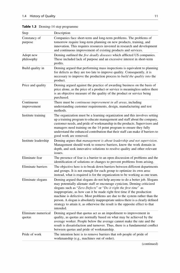
Table 1.3 Deming-14 step programme
Step Description
Constancy of
purpose
Companies face short-term and long-term problems. The problems of
tomorrow require long-term planning on new products, training, and
innovation. This requires resources invested in research and development
and continuous improvement of existing products and services.
Adopt new
philosophy
Deming outlined the five deadly diseases which afflicted US companies.
These included lack of purpose and an excessive interest in short-term
profits.
Build quality in Deming argued that performing mass inspections is equivalent to planning
for defects as they are too late to improve quality. Consequently, it is
necessary to improve the production process to build the quality into the
product.
Price and quality Deming argued against the practice of awarding business on the basis of
price alone, as the price of a product or service is meaningless unless there
is an objective measure of the quality of the product or service being
purchased.
Continuous
improvement
There must be continuous improvement in all areas, includingunderstanding customer requirements, design, manufacturing and test
methods.
Institute training The organization must be a learning organization and this involves setting
up a training program to educate management and staff about the company,
customer needs, and pride of workmanship in the products. Supervisors and
managers need training on the 14 point program to ensure they fully
understand the enhanced contribution that their staff can make if barriers to
good work are removed.
Institute leadership Deming argues that management is about leadership and not supervision.Management should work to remove barriers, know the work domain in
depth, and seek innovative solutions to resolve quality and other relevant
issues.
Eliminate fear The presence of fear is a barrier to an open discussion of problems and the
identification of solutions or changes to prevent problems from arising.
Eliminate barriers The objective here is to break down barriers between different departments
and groups. It is not enough for each group to optimize its own area:
instead, what is required is for the organization to be working as one team.
Eliminate slogans Deming argued that slogans do not help anyone to do a better job. Slogans
may potentially alienate staff or encourage cynicism. Deming criticized
slogans such as “Zero Defects” or “Do it right the first time” as
inappropriate, as how can it be made right first time if the production
machine is defective. Most problems are due to the system rather than the
person. A slogan is absolutely inappropriate unless there is a clearly defined
strategy to attain it, as otherwise the result is the opposite effect to that
intended.
Eliminate numerical
quotas
Deming argued that quotas act as an impediment to improvement in
quality, as quotas are normally based on what may be achieved by the
average worker. People below the average cannot make the rate and the
result is dissatisfaction and turnover. Thus, there is a fundamental conflict
between quotas and pride of workmanship.
Pride of work The intention here is to remove barriers that rob people of pride of
workmanship (e.g., machines out of order).
(continued)
1.4 History of Quality 11

Comment (Deming): Deming’s program has been quite influential and has manysound points. His views on slogans in the workplace are in direct opposition to theuse of slogans like Crosby’s “Zero defects”. The key point for Deming is that aslogan has no value unless there is a clear method to attain the particular goaldescribed by the slogan.
1.4.3 Juran
Joseph Juran (Fig. 1.5) was a major figure in the quality movement, and he argued
for a top down approach to quality. He defined quality as “fitness for use”, and he
argued that quality issues are the direct responsibility of management. Management
must ensure that quality is planned, controlled, and improved.
The trilogy of quality planning, control, and improvement is known as the
“Juran Trilogy”, and is usually described by a diagram with time on the horizontal
axis and the cost of poor quality on the vertical axis (Fig. 1.6).
Quality planning consists of setting quality goals, developing plans, and
identifying resources to meet the goals. Quality control consists of evaluating
performance, setting new goals, and taking action. Quality improvement consists
of improving delivery, eliminating wastage and improving customer satisfaction.
Juran’s10 step programme is defined in [33], and a summary is in Table 1.5.
Juran defined an approach to achieve a new quality performance level that is
termed “Breakthrough and Control”, It is described pictorially by a control chart
Table 1.3 (continued)
Step Description
Self improvement This involves encouraging education and self-improvement for everyone in
the company.
Take action This requires that management agree on direction using the 14 principles,
communicate the reasons for changes to the staff, and train the staff on the
14 principles.
Table 1.4 Deming – Five deadly diseases
Disease Description
Lack of constancy of
purpose
Management is too focused on short term thinking rather than long-term
improvements.
Emphasis on short
term profit
A company should aim to become the world’s most efficient provider of
product/service. Profits will then follow.
Evaluation of
performance
Deming is against annual performance appraisal and rating
Mobility of
management
Mobility of management frequently has a negative impact on quality.
Excessive
measurement
Excessive management by measurement.
12 1 Introduction

showing the old performance level with occasional spikes or random events; what is
needed is a breakthrough to a new and more consistent quality performance, i.e., a
new performance level with performance achieved at that level.
The example in Fig. 1.7 presents the breakthrough in developing a more accurate
estimation process. Initially the variation in estimation accuracy is quite large, but
as an improved estimation process is put in place, the control limits are narrowed
and more consistent estimation accuracy is achieved.
The breakthrough is achieved by a sustained and coordinated effort, and the old
performance standard becomes obsolete. The difference between the old and the
Fig. 1.5 Joseph Juran
Fig. 1.6 Cost of poor quality – % of sales
1.4 History of Quality 13

Table 1.5 Juran’s ten step programme
Step Description
Identify customers This includes the internal and external customers of an organization, e.g.,
the testing group is an internal customer and the end user of the software is
the external customer.
Determine customer
needs
Customer needs are generally expressed in the language of the customer’s
organization. There is a need to elicit and determine the actual desired
requirements with further communication with the customer.
Translate This involves translating the customer needs into the language of the
supplier.
Units of
measurement
This involves defining the measurement units to be used
Measurement
programme
This involves setting up a measurement program in the organization, and
includes internal and external measurements of quality and process
performance.
Develop product This step determines the product features to meet the needs of the
customer.
Optimize product
design
The intention is to optimize the design of the product to meet the needs of
the customer and supplier.
Develop process This involves developing processes which can produce the products to
satisfy the customer’s needs.
Optimize process
capability
This involves optimizing the capability of the process to ensure that high
quality products are produced.
Transfer This involves transferring the process to normal product development
operations.
Fig. 1.7 Estimation accuracy – Breakthrough and control
14 1 Introduction

new performance level is known as the “chronic disease” which must be diagnosed
and cured. His approach to breakthrough and control is (Table 1.6).
1.4.4 Crosby
Philip Crosby was a key figure in the quality movement, and his quality improve-
ment grid influenced the Capability Maturity Model (CMM) developed by the
Software Engineering Institute. His influential book Quality is Free [14] outlines
his philosophy of doing things right the first time, i.e., the zero defects(ZD) program. Quality is defined as “conformance to the requirements” and he
argues that people have been conditioned to believe that error is inevitable.
Crosby argued that people in their personal lives do not accept this: for example, it
would not be acceptable for nurses to drop a certain percentage of newly born babies.
He further argues that the term “Acceptable Quality Level” (AQL) is a commitment
to produce imperfect material. Crosby notes that defects are due to two main reasons:
lack of knowledge or a lack of attention of the individual.He argued that lack of knowledge can be measured and addressed by training,
but that lack of attention is a mind-set that requires a change of attitude by the
individual. The net effect of a successful implementation of a zero defects program
is higher productivity due to less reworking of defective products. Thus, quality, ineffect, is free.
Crosby’s approach to achieve the desired quality level of zero defects was to put
a quality improvement program in place. He outlined a 14 step quality improvement
program (Table 1.7). It requires management commitment to be successful, and an
organization-wide quality improvement team needs to be set up. A measurement
program is put in place to determine the status and cost of quality within the
organization. The cost of quality is then shared with the staff and corrective actions
are identified and implemented. The zero defect program is communicated to the
staff, and 1 day every year is made a zero defects day, and is used to emphasize the
importance of zero defects to the organization.
Crosby’s Quality ManagementMaturity Grid (Table 1.8) measures the maturity of
the current quality system with respect to several quality management categories, and
highlights areas which require improvement. Six categories of quality management
Table 1.6 Juran’s breakthrough and control
Step Description
Breakthrough in
attitude
This involves developing a favourable attitude to quality improvement.
Pareto This involves identifying the key areas affecting quality
Organization This involves analysing the problem and coordinating a solution.
Control This is concerned with achieving performance at the new level.
Repeat This leads to continuous improvement with new performance levels set and
breakthroughs made to achieve the new performance levels.
1.4 History of Quality 15

are considered: management understanding and attitude towards quality, qualityorganization status, problem handling, the cost of quality, quality improvementactions and summation of company quality posture.
Each category is rated on a 1–5 maturity scale and this indicates the maturity of
the particular category. Crosby’s maturity grid has been adapted and applied to the
CMM. The five levels are given in Table 1.8.
Comment (Crosby): Crosby’s program has been quite influential and his maturitygrid has been applied to the software CMM. The ZD part of the program is difficult to
Table 1.7 Crosby’s 14 step programme
Step Description
Management
commitment
Management commitment and participation is essential for the success of
the quality improvement program. The profile of quality is raised within the
organization
Quality
improvement team
This involves the formation of an organization-wide cross-functional team
consisting of representatives from each of the departments.
Quality
measurement
The objective of quality measurements is to determine the status of quality
in each area of the company and to identify areas where improvements are
required
Cost of quality
evaluation
The cost of quality is an indication of the financial cost of quality to the
organization. The cost is initially high, but as the quality improvement
becomes effective there is a reduction in the cost of quality.
Quality awareness This involves sharing the cost of poor quality with staff, and motivating
staff to identify corrective actions to address quality issues.
Corrective action This involves resolving any problems which have been identified, and
bringing any problems which cannot be resolved to the attention of
management.
Zero defect program The next step is to communicate the meaning of zero defects to the
employees The key point is that it is not a motivation program: instead, it
means doing things right the first time, i.e., zero defects.
Supervisor training This requires that all supervisors and managers receive training on the
14 step quality improvement program
Zero defects day This involves setting aside 1 day each year to high-light zero defects, and its
importance to the company.
Goal setting This phase involves getting people to think in terms of goals and achieving
the goals
Error cause removal This phase identifies any roadblocks or problems which prevent employees
from performing error-free work.
The list is produced from the list of problems or road-blocks for each
employee.
Recognition This involves recognizing employees who make out-standing contributions
to quality improvement.
Quality councils This involves bringing quality professionals together on a regular basis to
share ideas on action.
Do it over again The principle of continuous improvement is a key part of the programme.
Improvement is continuous.
16 1 Introduction

apply to the complex world of software development, where the complexities of thesystems to be developed are often the cause of defects rather than the mind-set ofsoftware professionals (who are generally dedicated to quality). Slogans may bedangerous and potentially unsuitable to some cultures and a zero defects day maypotentially have the effect of de-motivating staff.
1.4.5 Watts Humphrey
Watts Humphrey was an American software engineer and vice president of techni-
cal development at IBM. He made important contributions to the software engi-
neering field, and is considered the father of software quality. He dedicated much of
his career to addressing the problems of software development including schedule
delays, cost overruns, software quality and productivity (Fig. 1.8).
He was born in Michigan in 1927 and served in the US Navy and completed a
bachelor’s degree in physics at the University of Chicago in 1949. He obtained a
Master’s degree in physics from the Illinois Institute of Technology (IIT) and an
MBA from the University of Chicago.
He took a position with Sylvania in Boston in the early 1950s, and he became
manager of the circuit design group in the company. He recognized the importance
of planning and management early in his career, and he later made important
contributions to the management aspects of software development at IBM and the
Software Engineering Institute (SEI). He joined IBM in 1959 initially as a hardware
architect, but most of his IBM career was in management. He was eventually to
become a vice president of technical development, where he oversaw 4,000
Table 1.8 Crosby’s maturity grid
Level Name Description
1. Uncertainty: Management has no understanding of quality, and is likely to blame
quality problems on the quality department. Fire fighting is prevalent and
problems are fought as they occur. Root causes of problems are not
investigated, and there are few organized quality improvement activities.
2. Awakening: Management is beginning to recognize that quality management may be
of value, but is unwilling to devote time and money to it. Instead, the
emphasis is on appraisal rather than prevention. Teams are set up to
address major problems, but long-term solutions are rarely sought.
3. Enlightenment: Management is learning more about quality, and is becoming more
supportive of quality improvement. The quality department reports to
senior management, and implementation of the 14 step quality
improvement program is underway. There is a culture of openness where
problems are faced openly and resolved in an orderly way.
4. Wisdom: Management is fully participating in the program, and fully understands
the importance of quality management. All functions within the
organization are open to suggestions for improvement, and problems are
identified earlier. Defect prevention is now part of the culture.
5. Certainty: The whole organization is involved in continuous improvement
1.4 History of Quality 17

engineers in 15 development centres in over 7 countries. He was influenced by
others at IBM including Fred Brooks who was project manager of the IBM
360 project; Michael Fagan who developed the Fagan Inspection Methodology;
and Harlan Mills who developed the Cleanroom methodology. Humphries ran the
software quality and process group at IBM towards the end of his IBM career, and
became very interested in software quality.
He retired from IBM in 1986 and joined the newly formed SEI at Carnegie
Mellon University. He made a commitment to change the software engineering
world by developing sound management principles for the software industry. The
SEI has largely fulfilled this commitment, and it has played an important role in
enhancing the capability of software organizations throughout the world.
The SEI had a contract from the Department of Defence (DOD) to provide
guidance to the military in the selection of capable software subcontractors. This
evolved into the book “Managing the Software Process” [29] which describes
technical and managerial topics essential for good software engineering. The
book was influenced by the ideas of Deming and Juran in statistical process control.
Humphries established the software process programme at the SEI, and this led
to the development of the software Capability Maturity Model (CMM) and its
successors. Humphries asked questions such as:
– How good is the current software process?
– What must I do to improve it?
– Where do I start?
The CMM is a framework to help an organization to understand its current
process maturity, and to prioritize improvements. The SEI introduced software
process assessment and software capability evaluation methods, and these include
CBA/IPI and CBA/SCE. The CMM model and the associated assessment methods
were widely adopted by organizations around the world, and their successors are the
CMMI Model and the SCAMPI appraisal methodology.
Humphries focused his later efforts to developing the Personal Software Process
(PSP) and the Team Software Process (TSP). These are approaches that teach
engineers the skills they need to make and track plans, and to produce high-
quality software with zero defects. The PSP helps the individual engineer to collect
Fig. 1.8 Watts Humphrey
(Courtesy of Watts
Humphrey)
18 1 Introduction

relevant data for statistical process control, whereas the TSP focuses on teams, and
the goal is to assist teams to understand and improve their current productivity and
quality of their work.
He received many awards for his contributions to the computing field. He was
named the first SEI fellow in 1995 in recognition of his outstanding contribution to
the software quality field. He received the 2003 National Medal in Technology
from President George Bush, and was named an ACM fellow in 2009 for his
outstanding contributions to computing and information technology. He was the
author of 12 books in the software engineering field. He died in 2010.
1.4.6 Miscellaneous Quality Gurus
There are several other important pioneers in the quality field including Shingowhodeveloped his own version of zero defects termed “Poka yoke” (or defects¼ 0).This involves identifying potential error sources in the process, and monitoring
these for errors. Causal analysis is performed on any errors found, and the root
causes are eliminated. This approach leads to the elimination of all errors likely to
occur, and thus only exceptional errors should occur. These exceptional errors and
their causes are then eliminated. The failure mode and effects analysis (FMEA)
methodology is a variant of this. Potential failures to the system or sub-system are
identified and analysed, and the causes and effects and probability of failure
documented.
Genichi Taguchi’s definition of quality is quite different. Quality is defined as
“the loss a product causes to society after being shipped, other than losses causedby its intrinsic function”. Taguchi defines a loss function as a measure of the cost of
quality; L(x)¼ c(x� T)2 + k. Taguchi also developed a method for determining the
optimum value of process variables which will minimize the variation in a process
while keeping a process mean on target.
Kaoru Ishikawa is well known for his work in quality control circles (QCC).
A quality control circle is a small group of employees who do similar work, and meet
regularly to identify and analyse work-related problems. This involves brainstorming,
recommending and implementing solutions. The problem solving tools employed
include pareto analysis, fishbone diagrams, histograms, scatter diagrams, and con-trol charts. A facilitator will train the quality circle team leaders, and the activities in
a quality circle include:
• Select problem
• State and re-state problem
• Collect facts
• Brain-storm
• Build on each other’s ideas
• Choose course of action
• Presentation
Armand Feigenbaum is well known for this work in total quality control whichconcerns quality assurance applied to all functions in the organization. It is distinct
1.4 History of Quality 19

from total quality management: total quality control is concerned with controlling
quality throughout, whereas TQM embodies a philosophy of quality management
and improvement involving all staff and functions throughout the organization.
1.5 Modern Software Quality Management
The cost of correction of a defect increases the later that it is detected in the life
cycle. Consequently, it is desirable to detect an error as early as possible and
preferably within the phase in which it was created. This involves setting up a
software quality infrastructure to assist in error detection within the phase in which
the defect is created or at worst to detect the defect shortly after it exits the
particular phase. The development of high quality software requires a good soft-
ware development process to be in place, and this includes best practices in
software engineering for:
• Project management
• Estimation methodology
• Risk management process.
• Requirements Development and Management
• Design and Development
• Software development lifecycles
• Quality assurance/management
• Software inspections
• Software testing
• Supplier Selection and Management
• Configuration management
• Customer satisfaction process
• Continuous improvement
Mature software organizations are learning organizations and the goal is to learn
from defects to prevent their re-occurrence. Software inspections play a key role in
detecting defects in-phase, and they are discussed in the next section.
1.5.1 Software Inspections
The Fagan Inspection process was developed by Michael Fagan of IBM [20], and it
aims to identify and remove errors in work products. There is a strong economic
case for identifying defects as early as possible, as the cost of correction of a defect
increases the later that it is discovered. The process mandates that requirement
documents, design documents, source code, and test plans all be formally inspected
by experts independent of the author of the deliverable.
There are various roles defined in the process including the moderator who
chairs the inspection. The moderator ensures that all of the inspectors are trained
and receive the appropriate materials for the inspection. S/he ensures that sufficient
preparation is done, and that the speed of the inspection does not exceed the
20 1 Introduction

recommended guidelines. The reader reads or paraphrases the particular deliverable;the author is the creator of the deliverable and has a special interest in ensuring that itis correct. The tester role is concerned with the test viewpoint.
The inspection process will consider whether the design is correct with respect to
the requirements, and whether the source code is correct with respect to the design.
The errors identified are classified into various types and the data are generally
recorded to enable analysis to be performed on the most common types of errors.
The analysis will yield actions to be performed to minimize the re-occurrence of the
most common defect types. Software inspections are described in more detail in
Chap. 6.
1.5.2 Software Testing
Software testing plays a key role in verifying that the software is fit for purpose, and
two key types of software testing are black box and white box testing. White box
testing involves checking that every path in a module has been tested, and involves
defining and executing test cases to ensure code and branch coverage. The goal of
black box testing is to verify the functionality of a module or feature or the complete
system itself. Testing is both a constructive activity in that it is verifying the
correctness of functionality, and it may be a destructive activity in that the objective
is to find defects in the implemented software. Testing verifies that the requirements
are correctly implemented, and it yields the presence or absence of defects.
The test cases are reviewed by independent experts to ensure that they are
sufficient to verify the correctness of the software. There are various types of
testing including, unit, system, performance and usability testing. The effectiveness
of the testing is influenced by the maturity of the test process employed. Testing is
described in more detail in Chap. 7.
1.5.3 Software Quality Assurance
The IEEE definition of software quality assurance is “the planned and systematicpattern of all actions necessary to provide adequate confidence that the softwareperforms to established technical requirements” [41]. The software quality assur-
ance department provides visibility into the quality of the work products being
built, and the processes being used to create them. The quality assurance group may
be just one person operating part time or it may be a team of quality engineers. The
activities of the quality assurance group typically include software testing activities
to verify the correctness of the software, and also quality audits of the various
groups involved in software development. This section discusses the role of an
independent quality assurance group.
The quality group promotes quality in the organization and is independent of the
development group. It provides an independent assessment of the quality of the
product being built, and this viewpoint is independent of the project manager and
1.5 Modern Software Quality Management 21

development viewpoint. The quality assurance group acts as the voice of the
customer, and aims to ensure that quality is considered at each step in the process.
The quality group will perform audits of various projects, groups and departments,
and will determine the extent to which the process is followed and report any
weaknesses in the processes and non-compliances identified. The quality group will
usually have a reporting channel to senior management, and any non-compliance
issues which are not addressed at the project level may be escalated to the next level
of management for resolution. The key responsibilities of the quality assurance group
are:
• Promotes quality in organization
• Customer Advocate
• Conducts audits to verify Compliance
• Reports audit results to management
• Provides visibility to Management on processes followed
• Facilitates software process improvement
• Release sign-offs
The quality audit provides visibility into the work products and processes used to
develop the work products. The audit consists of an interview with the project team,
and the auditor examines the processes followed and deliverables produced by each
team member, considers any issues which have arisen during the work, and assesses
if there are any quality risks associated with the project based on the information
provided.
The auditor needs good written and verbal communication skills, and gathers
information via open and closed questions. S/he will need to observe behaviour and
body language and be able to deal effectively with any resistance. The auditor will
consider the role that the participant is performing, and relate this to the defined
process for their area. The entry and exit criteria to the defined processes are
generally examined to verify that the criteria have been satisfied at the various
milestones. The auditor writes a report detailing the findings from the audit and the
recommended corrective actions with respect to any identified non-compliance to
the defined procedures. S/he will perform follow-up activity at a later stage to verify
that the corrective actions have been carried out. The audit activities include
planning activities, the audit meeting, gathering data, reporting the findings and
assigning actions, and following the actions through to closure. The audit process is
described in more detail Chap. 9.
1.5.4 Problem Solving Techniques
There is a relationship between the quality of the process and the quality of the
products built from the process. The defects identified during testing are very
valuable in that they enable the organization to learn and improve from the defect.
Defects are often caused by the incorrect execution of a process, or due to a defect
in the process itself. Consequently, the lessons learned from a particular defect
should be used to correct systemic defects in the process.
22 1 Introduction

Problem-solving teams are formed to analyse various problems and to identify
corrective actions. They agree on the problem to be solved, the collection and
analysis of the facts, and determine the appropriate solution to solve the problem.
There are various tools to assist problem solving and these include fishbone
diagrams, histograms, trend charts, pareto diagrams, and bar charts. Problem
solving is discussed in detail in Chap. 10.
1.5.4.1 Fishbone DiagramsThis well-known cause-and-effect diagram is in the shape of the backbone of a fish.
The approach is to identify the possible causes of some particular quality effect.
These may include people, materials, methods, and timing. Each of the main causes
may then be broken down into sub-causes. The root cause is then identified, as often
80 % of problems are due to 20 % of causes (the 80:20 rule).
1.5.4.2 HistogramsA histogram is a way of representing data via a frequency distribution in bar chart
format, and it is a graphical representation of the underlying distribution of the data.
It illustrates the shape, variation, and centring of the underlying distribution. The
data is divided into a number of buckets, where a bucket is a particular range of data
values, and the relative frequency of each bucket is displayed in bar format. The
shape of the process and its spread from the mean is evident from the histogram.
1.5.4.3 Pareto ChartThe objective of a pareto chart is to identify the key problems and to focus on these.
Problems are classified into various types or categories, and the frequency of each
category of problem is then determined. The chart is displayed in a descending
sequence of frequency, with the most significant category detailed first, and the
least significant category detailed last. The success in problem-solving activities
over a period of time may be judged from the trends in the pareto chart, and if
problem solving activities are successful, then the key problem categories in the old
chart should show a noticeable improvement in the new pareto chart.
1.5.4.4 Trend GraphA trend graph is a graph of a variable over time and is a study of observed data for
trends or patterns over time.
1.5.4.5 Scatter GraphsThe scatter diagram is used to measure the relationship between variables, and to
determine whether there is a correlation between the variables. The results may be a
positive correlation, negative correlation or no correlation between the data. The
scatter diagram provides a means to confirm a hypothesis that two variables are
related, and provides a visual means to illustrate the potential relationship.
1.5 Modern Software Quality Management 23
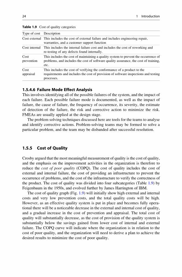
1.5.4.6 Failure Mode Effect AnalysisThis involves identifying all of the possible failures of the system, and the impact of
each failure. Each possible failure mode is documented, as well as the impact of
failure, the cause of failure, the frequency of occurrence, its severity, the estimate
of detection of the failure, the risk and corrective action to minimize the risk.
FMEAs are usually applied at the design stage.
The problem solving techniques discussed here are tools for the teams to analyse
and identify corrective actions. Problem-solving teams may be formed to solve a
particular problem, and the team may be disbanded after successful resolution.
1.5.5 Cost of Quality
Crosby argued that the most meaningful measurement of quality is the cost of quality,
and the emphasis on the improvement activities in the organization is therefore to
reduce the cost of poor quality (COPQ). The cost of quality includes the cost of
external and internal failure, the cost of providing an infrastructure to prevent the
occurrence of problems, and the cost of the infrastructure to verify the correctness of
the product. The cost of quality was divided into four subcategories (Table 1.9) by
Feigenbaum in the 1950s, and evolved further by James Harrington of IBM.
The cost of quality graph (Fig. 1.9) will initially show high external and internal
costs and very low prevention costs, and the total quality costs will be high.
However, as an effective quality system is put in place and becomes fully opera-
tional there will be a noticeable decrease in the external and internal cost of quality,
and a gradual increase in the cost of prevention and appraisal. The total cost of
quality will substantially decrease, as the cost of provision of the quality system is
substantially below the savings gained from lower cost of internal and external
failure. The COPQ curve will indicate where the organization is in relation to the
cost of poor quality, and the organization will need to derive a plan to achieve the
desired results to minimize the cost of poor quality.
Table 1.9 Cost of quality categories
Type of cost Description
Cost external This includes the cost of external failure and includes engineering repair,
warranties, and a customer support function
Cost internal This includes the internal failure cost and includes the cost of reworking and
re-testing of any defects found internally.
Cost
prevention
This includes the cost of maintaining a quality system to prevent the occurrence of
problems, and includes the cost of software quality assurance, the cost of training,
etc.
Cost
appraisal
This includes the cost of verifying the conformance of a product to the
requirements and includes the cost of provision of software inspections and testing
processes.
24 1 Introduction
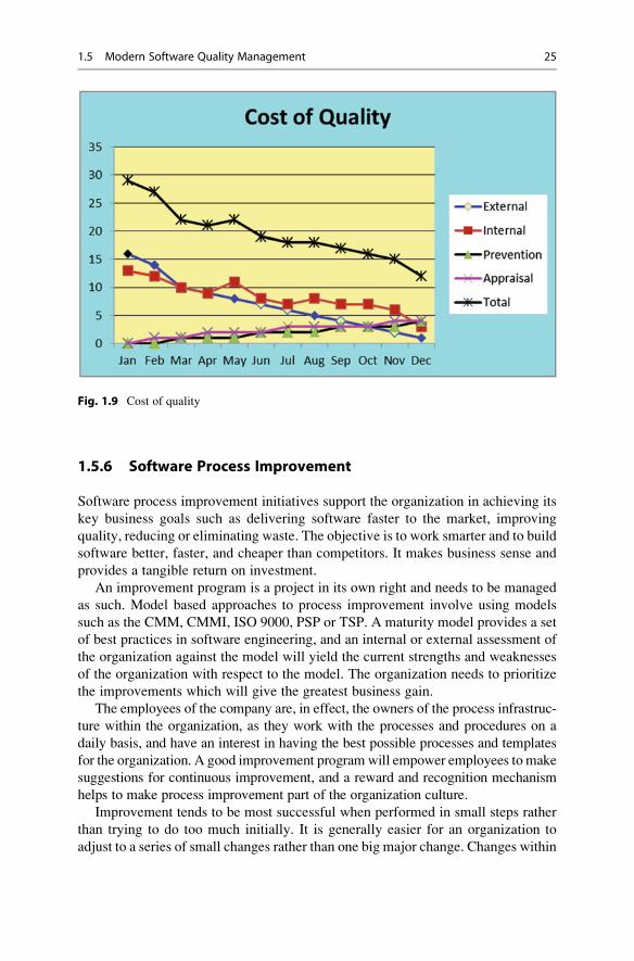
1.5.6 Software Process Improvement
Software process improvement initiatives support the organization in achieving its
key business goals such as delivering software faster to the market, improving
quality, reducing or eliminating waste. The objective is to work smarter and to build
software better, faster, and cheaper than competitors. It makes business sense and
provides a tangible return on investment.
An improvement program is a project in its own right and needs to be managed
as such. Model based approaches to process improvement involve using models
such as the CMM, CMMI, ISO 9000, PSP or TSP. A maturity model provides a set
of best practices in software engineering, and an internal or external assessment of
the organization against the model will yield the current strengths and weaknesses
of the organization with respect to the model. The organization needs to prioritize
the improvements which will give the greatest business gain.
The employees of the company are, in effect, the owners of the process infrastruc-
ture within the organization, as they work with the processes and procedures on a
daily basis, and have an interest in having the best possible processes and templates
for the organization. A good improvement programwill empower employees to make
suggestions for continuous improvement, and a reward and recognition mechanism
helps to make process improvement part of the organization culture.
Improvement tends to be most successful when performed in small steps rather
than trying to do too much initially. It is generally easier for an organization to
adjust to a series of small changes rather than one big major change. Changes within
Fig. 1.9 Cost of quality
1.5 Modern Software Quality Management 25

an organization need to be carefully planned and controlled. Training for the
existing employees may be required to ensure that they fully understand the
rationale for the proposed changes and are in a position to implement the proposed
changes in the organization.
1.5.7 Software Metrics
The use of measurement is an integral part of science and engineering disciplines,
and software measures are increasingly used in software engineering. The term
“software metric” was coined by Tom Gilb in his influential book on software
measurement [23]. The purpose of measurement in software engineering is to
provide an objective indication of the effectiveness of the organization in achieving
its key goals and objectives.
There is, of course, no point in measuring for the sake of measuring itself and care
is required to ensure that the measurements to be made are closely related to an
organization particular goal. The well-known approach of Goal, Question, Metric(GQM) suggests that the organization first needs to identify the key goals which it is
trying to achieve; then it identifies relevant questions which need to be answered to
assess the extent to which the goal is being satisfied, and then to formulate a metric to
give an objective answer to the particular question. This approach was formulated by
Victor Basilli and others, and is described in [2].
The use of measurement is invaluable in determining whether an organization
has actually improved, as actual quantitative data before and after the improvement
initiative can be compared and used to determine the extent of the improvements.
The initial measurements prior to the improvement program serve as the baseline
measurement, and these indicate the current capability and results of the organiza-
tion. A successful improvement programs will lead to improvements, and this will
be reflected in the metrics. The implementation of metrics involves:
• Business goals
• Questions related to goals
• Metrics
• Data gathering
• Presentation of charts
• Trends
• Action plans
Softwaremetrics are discussed in Chap. 10, and the chapter includes a collection of
sample metrics for the various functional areas in the organization. The metrics are
only as good as the underlying data, and data gathering is a key part of a metrics
program.
1.5.8 Customer Satisfaction
The effectiveness of the quality management system in delivering high-quality
software will ultimately be judged by the customer, and the level of customer
26 1 Introduction

satisfaction will determine whether the customer will purchase again from the
company, or recommend the company. Consumer research and customer satisfaction
surveys are used to determine the level of customer satisfaction with the company.
A customer satisfaction survey involves the customer rating the organization in
several key areas such as the quality of the software, its reliability, the timeliness of
the project, and so on. The customer satisfaction process takes the form of a closed
feedback loop, and the customer satisfaction feedback will be analysed and acted
upon appropriately.
The customer satisfaction survey is conducted, and the feedback analysed and
used to prepare the action plan. The actions are executed and the customer is
surveyed again at later date (Fig. 1.10). The follow up activity may involve a
telephone conversation with the customer or a visit to the customer to discuss the
specific issues. The issues are shared with engineering groups as appropriate. The
objective is to ensure that customers are totally satisfied with the product and
service, and a loyal customer will re-purchase and recommend the company to
other potential customers.
The customer satisfaction process is summarized as follows:
• Define customer surveys
• Send customer surveys
• Customer Satisfaction Ratings
• Customer meeting and key issues
• Action plans and follow-up
• Metrics for customer satisfaction
The definition of the questionnaire will vary depending on the nature of the
business. It is essential that the questionnaire is usable, and covers the relevant
questions to determine where the organization is weak (and in need of improve-
ment), and also to identify areas where it is strong. The questions typically employ a
rating scheme to allow the customer to give quantitative feedback on satisfaction,
and the survey will also enable the customer to go into more detail on issues.
Fig. 1.10 Customer
satisfaction process
1.5 Modern Software Quality Management 27

Software companies will be interested in the customer’s perception of the quality
of software, reliability, usability, timeliness of delivery, value for money, etc., and a
sample survey form is included in Table 1.10. This includes ten questions and may
be expanded as appropriate. A survey form will typically include open-ended
questions to enable the customer to give feedback in more detail.
Customer satisfaction metrics provide visibility into the level of customer
satisfaction with the software company, and enable trends to be determined. A
sample customer satisfaction metric is provided in Fig. 1.11, and it provides a
quantitative understanding of the level of customer satisfaction with the company.
Table 1.10 Sample customer satisfaction questionnaire
No /Question Unacceptable Poor Fair Satisfied Excellent N/A
1. Quality of software □ □ □ □ □ □
2. Ability to meet agreed dates □ □ □ □ □ □
3. Timeliness of projects □ □ □ □ □ □
4. Effective testing of software □ □ □ □ □ □
5. Expertise of staff □ □ □ □ □ □
6. Value for money □ □ □ □ □ □
7. Quality of support □ □ □ □ □ □
8. Ease of installation □ □ □ □ □ □
9. Ease of use □ □ □ □ □ □
10. Timely problem resolution □ □ □ □ □ □
Fig. 1.11 Customer satisfaction metrics
28 1 Introduction

1.5.9 Assessments (Appraisals)
The objective of an assessment (or appraisal) of an organization is to determine its
maturity with respect to a maturity model such as the CMMI or SPICE, or against
an international quality standard such as ISO 9000:2000.
The appraisal is performed by an external or internal assessment team, and yields
the strengths and weaknesses of the organization with respect to the model. The
appraisal report is used to plan and prioritize future improvements.
The appraisal is a major review of the organization and it needs to be carefully
planned. The assessment team needs sufficient expertise and experience, and the
appraisal may take 1–2 weeks. It involves interviews with the project managers and
project teams as well as the review of relevant documentation. The assessment
report will detail the extent to which the model is implemented, and any gaps and
improvement opportunities are highlighted in the report.
The SCAMPI methodology is used for CMMI appraisals, and it is discussed in
Chap. 15.
1.5.10 Total Quality Management
Total quality management (TQM) is a management philosophy to focus attention
on quality and to develop a culture of quality within the organization. Quality is a
company-wide objective, and the organization goal is total customer satisfaction.
The organization aims to deliver products and services that totally satisfy the
customer needs. It is a holistic approach and it applies to all levels and functions
within the organization.
TQM employs many of the ideas of the pioneers in the quality movement.
Management are required to take charge of the implementation of quality manage-
ment, and all staff will need to be trained in quality improvement activities.
The implementation of TQM involves a focus on all areas within the organiza-
tion, and in identifying areas for improvement. The problems in the particular area
are evaluated and data is collected and analysed. An action plan is then derived and
the actions implemented and monitored. This is then repeated for continuous
improvement. The implementation is summarized as follows:
• Identify improvement area
• Problem evaluation
• Data collection
• Data analysis
• Action plan
• Implementation of actions
• Monitor effectiveness
• Repeat
There are four main parts of TQM (Table 1.11).
1.5 Modern Software Quality Management 29

The ISO 9000 standard (see Chap. 11) is a structured approach to the implemen-
tation of TQM. Its clauses are guidelines for what needs to be done, and include
requirements to be satisfied for the organization to satisfy ISO 9000.
1.6 Miscellaneous
Software quality management is, in many ways, the application of common sense to
software engineering. It makes sense to plan and track a project, identify potential
risks early and attempt to eliminate or reduce their impact; determine the
requirements, produce a design, review the design and development activities for
correctness. It is sensible to test the software against the requirements, to record any
problems identified, and to correct them. It is sensible to have objective criteria to
determine if the software is ready to be released to the customer, and to learn any
lessons from the project and to survey customers to obtain valuable feedback.
1.6.1 Organization Culture and Change
Every organization has a distinct culture and this reflects the way in which things
are done in the company. Organization culture includes the ethos of the organiza-
tion, its core values, its history, its success stories, its people, amusing incidents,
and so on. The culture of the organization may be favourable or unfavourable to
developing high-quality software.
Occasionally a change to the organization culture is required, and this may be
difficult as it could involve changing its fundamental approach to software devel-
opment, and there may be a resistance to this. Successful change management often
involves the following:
• Kick-off meeting
• Motivate rationale for changes
Table 1.11 Total quality management
Part Description
Customer focus This involves identifying internal and external customers and recognizing
that all customers have expectations and rights which need to be satisfied
first time and every time. Quality must be considered in every aspect of the
business, and the focus is on fire prevention.
Process This involves a focus on the process and improvement to the process via
problem solving. The improvements will reduce waste and eliminate error.
Measurement and
analysis
This involves setting up a measurement program within the organization to
enable objective and effective analysis of the quality of the process and
product
Human factors This involves developing a culture of quality and customer satisfaction
throughout the organization. The core values of quality and customer
satisfaction need to be instilled in the organization. This requires training
for the employees on quality, customer satisfaction, and continuous
improvement.
30 1 Introduction
• Present plan
• Training
• Implement changes
• Monitor implementation
• Institutionalize
The culture of an organization is often illustrated by the phrase: “That’s the waywe do things around here”. For example, the evolution from one level of the CMM
to another often involves a change the way that things are done in the organization.
The focus on prevention requires a change in mind-set to focus on problem solvingand fire prevention, rather than on fire fighting.
1.6.2 Law of Negligence
The impact of a flaw in software may be catastrophic, and several software failures
were discussed earlier in this chapter. Clearly, every organization must take all
reasonable precautions to prevent the occurrence of defects, especially in the safety
critical domain where defects may cause major damage or even loss of life. Reason-
able precautions consist of having appropriate software engineering practices in place
to allow the organization to consistently produce high quality software.
A quality management system indicates that the organization takes software
quality seriously. The objective of the quality management system is to put a sound
software development process in place that serves the needs of the organization and
its customers. Modem quality assurance systems include processes for software
inspections, testing, quality audits, customer satisfaction, software development,
project planning, etc.
The organization will require evidence or records to prove that the quality
management system is in place, that it is appropriate for the organization, and
that it is fully operational within the organization. The proof that the quality system
is actually operational typically takes the form of records of the various activities.
The records also enable the organization to prepare a legal defence to show that it
took all reasonable precautions in software development, especially if a customer
decides to take legal action for negligence against the software provider following a
serious problem in the software at the customer environment.
The presence of records may be used to indicate that all reasonable steps were
taken, and the records typically include lists of all the deliverables in the project;
minutes of project meetings; records of reviews of requirements, design, and
software code, records of test plans and test results; and so on.
1.6.3 Quality and the WEB
The explosive growth of the World Wide Web and electronic commerce has made
the quality of web sites a key concern. Web technology is rapidly becoming
ubiquitous in society, and is quite distinct from other software systems in that:
1.6 Miscellaneous 31
• It may be accessed from anywhere in the world.
• It may be accessed by many different browsers.
• The usability and look and feel of the application is a key concern.
• The performance of the web site is a key concern.
• Security is a key concern.
• The web site must be capable of dealing with a large number of transactions at
any time.
• The web site has very strict availability constraints (typically 24� 365).
• The web site needs to be highly reliable.
It is inappropriate to employ the waterfall lifecycle for this domain, and usually a
spiral lifecycle will be employed as the requirements are often incomplete at project
initiation and evolve to the agreed set during the project. Often, Rapid Application
Development (RAD) or Joint ApplicationDevelopment (JAD) lifecycle are employed.
1.7 Review Questions
1. Discuss the contributions of Deming and Juran.
2. Describe Crosby’s maturity grid and discuss how it influenced the Capa-
bility Maturity Model?
3. Explain why Watts Humphrey is considered the father of software quality.
4. Explain the difference between software inspections and testing?
5. What is an assessment (appraisal) and explain how it forms part of the
improvement cycle.
6. Explain the importance of the cost of poor quality.
7. Discuss the importance of software metrics in problem solving.
8. Explain the importance of customer satisfaction and describe how it may
be measured.
1.8 Summary
This chapter provided a short introduction to the software quality field, and the
discussion covered the contributions of various pioneers such as Shewhart, Deming,
Juran and Crosby. The contributions of Watts Humphrey, who is considered the
father of software quality, were also discussed.
We examined various definitions of quality such as Crosby’s “conformance to
the requirements” and Juran’s “fitness for purpose”, as well as considering the
various dimensions of software product quality listed in ISO 9126.
We considered various software failures such as the Ariane 5 disaster, the year
2000 problem, and a maths bug in the Intel microprocessor in the mid-1990s. A
software failure may lead to loss of life, a telecoms outage, the loss of a rocket and
its satellite cargo, and the loss of credibility of the company. Consequently, there is
a strong economic case to consistently develop high-quality software.
32 1 Introduction

Wediscussedmodern software qualitymanagement including software inspections
that are used to build quality into the software; software testing to verify that the
software is of high quality as well as finding defects in the software; software quality
assurance to provide visibility into the processes and the extent to which they are
followed; problem solving techniques to prevent problems from re-occurring; the cost
of poor quality to the organization; software process improvement to improve the key
processes in the organization; and customer satisfaction to determine the level of
customer satisfaction with the organization.
1.8 Summary 33
Software Engineering 2
Key Topics
Standish Chaos Report
Software Lifecycles
Waterfall Model
Spiral Model
Rational Unified Process
Agile Development
Software Inspections
Software Testing
Project Management
2.1 Introduction
The approach to software development in the 1950s and 1960s has been described
as the “Mongolian Hordes Approach” by Ince and Andrews [30]. The “method” or
lack of method was characterized by:
The completed code will always be full of defects.The coding should be finished quickly to correct these defects.Design as you code approach.
This philosophy accepted defeat in software development, and suggested that
irrespective of a solid engineering approach, that the completed software would
always contain lots of defects, and that it therefore made sense to code as quickly as
possible, and to then identify the defects that would be present, so as to correct them
as soon as possible.
G. O’Regan, Introduction to Software Quality, Undergraduate Topicsin Computer Science, DOI 10.1007/978-3-319-06106-1_2,# Springer International Publishing Switzerland 2014
35

In the late 1960s it was clear that the existing approaches to software development
were deeply flawed, and that there was an urgent need for change. The NATO
Science Committee organized two famous conferences to discuss critical issues in
software development [12], with the first conference held at Garmisch, Germany, in
1968, and it was followed by a second conference in Rome in 1969.
Over 50 people from 11 countries attended the Garmisch conference, including
Edsger Djkstra, who did important theoretical work on formal specification and
verification. The NATO conferences highlighted problems that existed in the
software sector in the late 1960s, and the term “software crisis” was coined to
refer to these problems. These included budget and schedule overruns, as well as
problems with the quality and reliability of the delivered software.
The conference led to the birth of software engineering as a discipline in its ownright, and the realization that programming is quite distinct from science and
mathematics. Programmers are like engineers in that they build software products,
and they therefore need education in traditional engineering as well as the latest
technologies. The education of a classical engineer includes product design and
mathematics. However, often computer science education places an emphasis on
the latest technologies rather than the important engineering foundations of design-
ing and building high-quality products that are safe for the public to use.
Programmers therefore need to learn the key engineering skills to enable them to
build products that are safe for the public to use. This includes a solid foundation
on design and the mathematics required for building safe software products.
Mathematics plays a key role in engineering and may assist software engineers in
the delivery of high-quality software products. Several mathematical approaches to
assist software engineers are described in [48].
There are parallels between the software crisis in the late 1960s, and serious
problems with bridge construction in the nineteenth century. Several bridges
collapsed or were delivered late or over-budget due to the fact that people involved
in their design and construction did not have the required engineering knowledge.
This led to bridges that were inadequately designed and constructed, leading to their
collapse with the loss of life and endangering the lives of the public.
This led to legislation requiring engineers to be licensed by the Professional
Engineering Association prior to practicing as engineers. This organization identified
a core body of knowledge that the engineer is required to possess, and the licensing
body verifies that the engineer has the required qualifications and experience. This
helps to ensure that only personnel competent to design and build products actually
do so. Engineers have a professional responsibility to ensure that the products are
properly built and are safe for the public to use.
The Standish group has conducted research (Fig. 2.1) on the extent of problems
with IT projects since the mid-1990s. These studies were conducted in the United
States, but there is no reason to believe that European or Asian companies perform
any better. The results indicate serious problems with on-time delivery of projects
or projects being cancelled prior to completion.1 However, the comparison between
1 These are IT projects covering diverse sectors including banking, telecommunications, etc.,
rather than pure software companies. Software companies following maturity frameworks such
as the CMMI generally achieve more consistent project, and the CMMI focuses on the manage-
ment side of software engineering.
36 2 Software Engineering
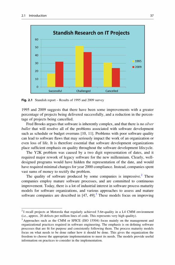
1995 and 2009 suggests that there have been some improvements with a greater
percentage of projects being delivered successfully, and a reduction in the percen-
tage of projects being cancelled.
Fred Brooks argues that software is inherently complex, and that there is no silverbullet that will resolve all of the problems associated with software development
such as schedule or budget overruns [10, 11]. Problems with poor software quality
can lead to software flaws that may seriously impact the work of an organization or
even loss of life. It is therefore essential that software development organizations
place sufficient emphasis on quality throughout the software development lifecycle.
The Y2K problem was caused by a two digit representation of dates, and it
required major rework of legacy software for the new millennium. Clearly, well-
designed programs would have hidden the representation of the date, and would
have required minimal changes for year 2000 compliance. Instead, companies spent
vast sums of money to rectify the problem.
The quality of software produced by some companies is impressive.2 These
companies employ mature software processes, and are committed to continuous
improvement. Today, there is a lot of industrial interest in software process maturity
models for software organizations, and various approaches to assess and mature
software companies are described in [47, 49].3 These models focus on improving
Fig. 2.1 Standish report – Results of 1995 and 2009 survey
2 I recall projects at Motorola that regularly achieved 5.6σ-quality in a L4 CMM environment
(i.e., approx. 20 defects per million lines of code. This represents very high quality).3 Approaches such as the CMM or SPICE (ISO 15504) focus mainly on the management and
organizational practices required in software engineering. The emphasis is on defining software
processes that are fit for purpose and consistently following them. The process maturity models
focus on what needs to be done rather how it should be done. This gives the organization the
freedom to choose the appropriate implementation to meet its needs. The models provide useful
information on practices to consider in the implementation.
2.1 Introduction 37

the effectiveness of the management, engineering and organization practices related
to software engineering, and in introducing best practice in software engineering.
The disciplined use of the mature software processes by the software engineers
enables high-quality software to be consistently produced.
2.2 What Is Software Engineering?
Software engineering involves the multi-person construction of multi-version
programs. The IEEE 610.12 definition of Software Engineering is:
Software engineering is the application of a systematic, disciplined, quantifiable approach
to the development, operation, and maintenance of software; that is, the application of
engineering to software, and the study of such approaches.
Software engineering includes:
1. Methodologies to design, develop, and test software to meet customers’ needs.
2. Software is engineered. That is, the software products are properly designed,
developed, and tested in accordance with engineering principles.
3. Quality and safety are properly addressed.
4. Mathematics may be employed to assist with the design and verification of
software products. The level of mathematics employed will depend on the safetycritical nature of the product. Systematic peer reviews and rigorous testing will
often be sufficient to build quality into the software, with heavy mathematicaltechniques reserved for safety and security critical software.
5. Sound project management and quality management practices are employed.
6. Support and maintenance of the software is properly addressed.
Software engineering is not just programming. It requires the engineer to state
precisely the requirements that the software product is to satisfy, and then to produce
designs that will meet these requirements. The project needs to be planned and
delivered on time and budget. The requirements must provide a precise description
of the problem to be solved: i.e., it should be evident from the requirements whatis and what is not required. The requirements need to be rigorously reviewed to
ensure that they are stated clearly and unambiguously and are exactly what the
customer wants. The next step is then to create the design that will solve the problem,
and it is essential to validate the correctness of the design. Next, the software to
implement the design is written, and peer reviews and software testing are employed
to verify and validate the correctness of the software.
The verification and validation of the design is rigorously performed for safety
critical systems, and it is sometimes appropriate to employ mathematical tech-
niques for these systems. However, it will usually be sufficient to employ peer
reviews or software inspections as these methodologies provide a high degree of
rigour. This may include approaches such as Fagan inspections [20], Gilb inspec-
tions [24], or Prince 2’s approach to quality reviews [51].
The term “engineer” is a title that is awarded on merit in classical engineering.
It is generally applied only to people who have attained the necessary education
38 2 Software Engineering
and competence to be called engineers, and who base their practice on classical
engineering principles. The title places responsibilities on its holder such as to
behave professionally and ethically. Often in computer science the term “softwareengineer” is employed loosely to refer to anyone who builds things, rather than to
an individual with a core set of knowledge, experience, and competence.
Several computer scientists (such as Parnas4) have argued that computer scientists
should be educated as engineers to enable them to apply appropriate scientific
principles to their work. They argue that computer scientists should receive a solid
foundation in mathematics and design, to enable them to have the professional
competence to perform as engineers in building high-quality products that are safe
for the public to use. The use of mathematics is an integral part of the engineer’s work
in other engineering disciplines, and so the software engineer should be able to use
mathematics to assist in the modelling or understanding of the behaviour or properties
of a proposed software system.
Software engineers need education5 on specification, design, turning designs
into programs, software inspections, and testing. The education should enable the
software engineer to produce well-structured programs that are fit for purpose.
Parnas has argued that software engineers have responsibilities as professional
engineers.6 They are responsible for designing and implementing high-quality and
reliable software that is safe to use. They are also accountable for their decisions
and actions,7 and have a responsibility to object to decisions that violate professional
4 Parnas has made important contributions to computer science. He advocates a solid engineering
approach with the extensive use of classical mathematical techniques to software development.
He also introduced information hiding in the 1970s which is now a part of object-oriented
development.5 Software Companies that are following approaches such as the CMM or ISO 9001 consider
the education and qualification of staff prior to assigning staff to performing specific tasks.
The appropriate qualifications and experience for the specific role are considered prior to
appointing a person to carry out the role. Many companies are committed to the education and
continuous development of their staff, and on introducing best practice in software engineering
into their organization..6 The concept of accountability was used by the ancient Babylonians, and they employed a code of
laws (known as the Hammurabi Code) c. 1750 B.C. It included a law that stated that if a house
collapsed and killed the owner then the builder of the house would be executed.7 However, it is unlikely that an individual programmer would be subject to litigation in the case of
a flaw in a program causing damage or loss of life. A comprehensive disclaimer of responsibility
for problems rather than a guarantee of quality accompany most software products. Software
engineering is a team-based activity involving many engineers in various parts of the project, and it
would be potentially difficult for an outside party to prove that the cause of a particular problem is
due to the professional negligence of a particular software engineer, as there are many others
involved in the process such as reviewers of documentation and code and the various test groups.
Companies are more likely to be subject to litigation, as a company is legally responsible for the
actions of their employees in the workplace, and a company is a wealthier entity than one of its
employees. The legal aspects of licensing software may protect software companies from liti-
gation. However, greater legal protection for the customer can be built into the contract between
the supplier and the customer for bespoke-software development.
2.2 What Is Software Engineering? 39

standards. Engineers are required to behave professionally and ethically with their
clients. The membership of the professional engineering body requires the member to
adhere to the code of ethics8 of the profession. Engineers in other professions are
licensed, and therefore Parnas argues that a similar licensing approach be adopted for
professional software engineers9 to provide confidence that they are competent for
the particular assignment. Professional software engineers are required to follow best
practice in software engineering and the defined software processes.10
Many software companies invest heavily in training as the education and
knowledge of its staff are essential to delivering high-quality products and services.
Employees in receive professional training related to the roles that they are
performing, such as project management, service management, and software
testing. The fact that the employees are professionally qualified increases confi-
dence in the ability of the company to deliver high-quality products and services.
A company that pays little attention to the competence and continuous development
of its staff will suffer a loss of reputation and market share.
2.3 Challenges in Software Engineering
The challenge in software engineering is to deliver high-quality software on time and
on budget to customers. The research done by the Standish Group was discussed
earlier in this chapter, and the results of their 1998 research (Fig. 2.2) on project cost
overruns in the US indicated that 33 % of projects are between 21 and 50 % over
estimate, 18 % are between 51 and 100 % over estimate, and 11 % of projects are
between 101 and 200 % overestimate.
The accurate estimation of project cost, effort and schedule is a challenge in
software engineering. Therefore, project managers need to determine how good
their estimation process actually is and to make appropriate improvements. The use
of software metrics is an objective way to do this, and improvements in estimation
will be evident from a reduced variance between estimated and actual effort.
The project manager will determine and report the actual versus estimated effort
and schedule for the project.
Risk management is an important part of project management, and the objective
is to identify potential risks early and throughout the project, and to manage them
8Many software companies have a defined code of ethics that employees are expected to adhere.
Larger companies will wish to project a good corporate image and to be respected worldwide.9 The British Computer Scientist (BCS) has introduced a qualification system for computer science
professionals that it used to show that professionals are properly qualified. The most important of
these is the BCS Information Systems Examination Board (ISEB) which allows IT professionals to
be qualified in service management, project management, software testing, and so on.10 Software companies that are following the CMMI or ISO 9000 standards will employ audits to
verify that the processes and procedures have been followed. Auditors report their findings to
management and the findings are addressed appropriately by the project team and affected
individuals.
40 2 Software Engineering

appropriately. The probability of each risk occurring and its impact is determined
and the risks are managed during project execution.
Software quality needs to be properly planned to enable the project to deliver a
quality product. Flaws with poor quality software lead to a negative perception of
the company, and could potentially lead to damage to the customer relationship
with a subsequent loss of market share.
There is a strong economic case to building quality into the software, as less
time is spent in re-working defective software. The cost of poor quality (COPQ)
should be measured and targets set for its reductions. It is important that lessons are
learned during the project and acted upon appropriately. This helps to promote a
culture of continuous improvement.
We discussed a number of high-profile software failures in the previous chapter.
These included the millennium bug (Y2K) problem; the floating point bug in the
Intel microprocessor; the European Space Agency Ariane-5 disaster, and so on.
These have caused embarrassment to the organizations as well as the cost of
replacement and correction.
The millennium bug was due to the use of two digits to represent dates rather
than four digits. The solution involved finding and analysing all code that that had
a Y2K impact; planning and making the necessary changes; and verifying the
correctness of the changes. The worldwide cost of correcting the millennium bug
is estimated to have been in billions of dollars.
The Intel Corporation was slow to acknowledge the floating-point problem in
its Pentium microprocessor, and in providing adequate information on its impact
to its customers. It incurred a large financial cost in replacing microprocessors for
its customers. The Ariane-5 failure caused major embarrassment and damage to the
credibility of the European Space Agency (ESA). Its maiden flight ended in failure
on June 4, 1996, after a flight time of just 40 s.
Fig. 2.2 Standish 1998 report – Estimation accuracy
2.3 Challenges in Software Engineering 41

These failures indicate that quality needs to be carefully considered when
designing and developing software. The effect of software failure may be large
costs to correct the software, loss of credibility of the company, or even loss of life.
2.4 Software Processes and Lifecycles
Organizations vary by size and complexity, and the processes employed will reflect
the nature of their business. The development of software involves many processes
such as those for defining requirements; processes for project management and
estimation; processes for design, implementation, testing, and so on.
It is important that the processes employed are fit for purpose, and a key premise
in the software quality field is that the quality of the resulting software is influenced
by the quality and maturity of the underlying processes, and compliance to them.
Therefore, it is necessary to focus on the quality of the processes as well as the
quality of the resulting software.
There is, of course, little point in having high-quality processes unless their use
is institutionalized in the organization. That is, all employees need to follow the
processes consistently. This requires that people are trained on the new processes
and that process discipline is instilled by an appropriate audit strategy.
Employees need to be trained on the processes, and audits are conducted
to ensure process compliance. Data will be collected to improve the process.
The software process assets in an organization generally consist of:
– A software development policy for the organization
– Process maps that describe the flow of activities
– Procedures and guidelines that describe the processes in more detail.
– Checklists to assist with the performance of the process
– Templates for the performance of specific activities (e.g., Design, Testing)
– Training Materials
The processes employed to develop high-quality software generally include
processes for:
– Project Management Process
– Requirements process
– Design Process
– Coding Process
– Peer Review Process
– Testing Process
– Supplier Selection and Management processes
– Configuration Management process
– Audit process
– Measurement Process.
– Improvement Process
– Customer Support and Maintenance processes
The software development process has an associated lifecycle that consists of
various phases. There are several well-known lifecycles employed such as the
42 2 Software Engineering

waterfall model [56]; the spiral model [8], the Rational Unified Process [57] and the
Agile methodology [3] which has become popular in recent years. The choice of a
particular software development lifecycle is determined from the particular needs
of the specific project. The various lifecycles are described in more detail in the
following Sections.
2.4.1 Waterfall Lifecycle
The waterfall model11 (Fig. 2.3) starts with requirements gathering and definition.
It is followed by the functional specification, the design and implementation of the
software, and comprehensive testing. The testing generally includes unit, system
and user acceptance testing.
It is employed for projects where the requirements can be identified early in the
project lifecycle or are known in advance. It is also called the “V” life cycle model,
with the left-hand side of the “V” detailing requirements, specification, design, and
coding and the right-hand side detailing unit tests, integration tests, system tests
and acceptance testing. Each phase has entry and exit criteria that must be satisfied
before the next phase commences. There are several variations to the waterfall model.
Many companies employ a set of templates to enable the activities in the various
phases to be consistently performed. Templates may be employed for project
planning and reporting; requirements definition; design; testing and so on. These
templates may be based on the IEEE standards or industrial best practice.
11We treat the waterfall model as identical to the V model in this text.
Fig. 2.3 Waterfall V lifecycle model
2.4 Software Processes and Lifecycles 43

2.4.2 Spiral Lifecycles
The spiral model (Fig. 2.4) was developed by Barry Boehm in the mid-1980s, and is
useful for a project in which the requirements are not fully known at project
initiation, or where the requirements evolve as a part of the development lifecycle.
The development proceeds in a number of spirals, where each spiral typically
involves objectives and an analysis of the risks, updates to the requirements, design,
code, testing, and a user review of the particular iteration or spiral.
The spiral is, in effect, a re-usable prototype with the business analysts and the
customer reviewing the current iteration, and providing feedback to the development
team. The feedback is analysed and used to plan the next iteration. This approach is
often used in joint application development, where the usability and look and feel of
the application is a key concern. This is important in web-based development and
in the development of a graphical user interface (GUI). The implementation of part of
the system helps in gaining a better understanding of the requirements of the system,
and this feeds into subsequent development cycle. The process repeats until the
requirements and the software product are fully complete.
Fig. 2.4 SPIRAL lifecycle model . . . Public domain
44 2 Software Engineering
There are several variations of the spiral model including Rapid Application
Development (RAD); Joint Application Development (JAD) models; and the
Dynamic Systems Development Method (DSDM) model. Agile methods have
become popular in recent years and these generally employ sprints (or iterations)
of 2 weeks duration to implement a number of user stories. A sample spiral model is
shown in Fig. 2.4.
There are other life-cycle models, for example, the iterative development
process that combines the waterfall and spiral lifecycle model. The Cleanroom
approach developed by Harlan Mills at IBM includes a phase for formal specifica-
tion, and its approach to software testing is based on the predicted usage of the
software product. The Rational Unified Process has become popular in recent years,
and it is discussed in the next section.
2.4.3 Rational Unified Process
The Rational Unified Process [57] was developed at the Rational Corporation
(now part of IBM). It uses the Unified Modelling Language (UML) as a tool for
specification and design, and UML is a visual modelling language for software
systems which provides a means of specifying, constructing, and documenting
the object-oriented system. It was developed by James Rumbaugh, Grady Booch,
and Ivar Jacobson, and it facilitates the understanding of the architecture and
complexity of the system.
RUP is use case driven, architecture centric, iterative and incremental, andincludes cycles, phases, workflows, risk mitigation, quality control, project man-
agement, and configuration control. Software projects may be very complex, and
there are risks that requirements may be incomplete, or that the interpretation of a
requirement may differ between the customer and the project team.
Requirements are gathered as use cases, and the use cases describe the func-tional requirements from the point of view of the user of the system. They describe
what the system will do at a high level, and ensure that there is an appropriate
focus on the user when defining the scope of the project. Use cases also drive thedevelopment process, as the developers create a series of design and imple-
mentation models that realize the use cases. The developers review each successive
model for conformance to the use-case model, and the test team verifies that the
implementation correctly implements the use cases.
The software architecture concept embodies the most significant static and
dynamic aspects of the system. The architecture grows out of the use cases and
factors such as the platform that the software is to run on, deployment conside-
rations, legacy systems, and non-functional requirements.
RUP decomposes the work in a large project into smaller slices or mini-projects,
and each mini-project is an iteration that results in an increment to the product.The iteration consists of one or more steps in the workflow, and generally leads to
the growth of the product. If there is a need to repeat an iteration, then all that is lost
is the misdirected effort of one iteration, rather that the entire product. Another
words, RUP is a way to mitigate risk in software engineering.
2.4 Software Processes and Lifecycles 45

2.4.4 Agile Development
There has been a growth of popularity among software developers in lightweight
methodologies such as Agile. This is a software development methodology that
claims to be more responsive to customer needs than traditional methods such as the
waterfall model. The waterfall development model is similar to a wide and slowmoving value stream, and halfway through the project 100 % if the requirements are
typically 50 % done. However, for agile development 50 % of requirements aretypically 100 % done halfway through the project.
This methodology has a strong collaborative style of working and its approach
includes:
– Aim is to achieve a narrow fast flowing value stream
– Feedback and adaptation employed in decision making
– User Stories and sprints are employed
– Stories are either done are not done
– Iterative and Incremental development is employed
– A project is divided into iterations
– An iteration has a fixed length (i.e., Time boxing is employed)
– Entire software development lifecycle is employed for the implementation of
each story
– Change is accepted as a normal part of life in the Agile world
– Delivery is made as early as possible.
– Maintenance is seen as part of the development process
– Refactoring and Evolutionary Design Employed
– Continuous Integration is employed
– Short Cycle Times
– Emphasis on Quality
– Stand Up Meetings
– Plan regularly
– Direct interaction preferred over documentation
– Rapid conversion of requirements into working functionality
– Demonstrate value early
– Early decision making
Ongoing changes to requirements are considered normal in the Agile world, and itis believed to be more realistic to change requirements regularly throughout the
project rather than attempting to define all of the requirements at the start of the
project. The methodology includes controls to manage changes to the requirements,
and good communication and early regular feedback is an essential part of the process.
A story may be a new feature or a modification to an existing feature. It is reducedto the minimum scope that can deliver business value, and a feature may give rise
to several stories. Stories often build upon other stories and the entire software
development lifecycle is employed for the implementation of each story. Storiesare either done or not done: i.e., there is such thing as a story being 80 % done.
46 2 Software Engineering

The story is complete only when it passes its acceptance tests. Stories are prioritized
based on a number of factors including:
– Business Value of Story
– Mitigation of risk
– Dependencies on other stories.
Sprint planning is performed before the start of the iteration, and stories are
assigned to the iteration to fill the available time. The estimates for each story and
their priority are determined, and the prioritized stories are assigned to the iteration.
A short morning stand up meeting is held daily during the iteration, and attended
by the project manager and the project team. It discusses the progress made the
previous day, problem reporting and tracking, and the work planned for the day
ahead. A separate meeting is held for issues that require more detailed discussion.
Once the iteration is complete the latest product increment is demonstrated to an
audience including the product owner. This is to receive feedback and to identify
new requirements. The team also conducts a retrospective meeting to identify what
went well and what went poorly during the iteration. This is to for continuous
improvement for future iterations.
Agile employs pair programming and a collaborative style of working with thephilosophy that two heads are better than one. This allows multiple perspectives
in decision making and a broader understanding of the issues.
Software testing is very important and Agile generally employs automated
testing for unit, acceptance, performance and integration testing. Tests are run
frequently with the goal of catching programming errors early. They are generally
run on a separate build server to ensure that all dependencies are checked. Tests are
re-run before making a release. Agile employs test driven development with testswritten before the code. The developers write code to make a test pass with ideally
developers only coding against failing tests. This approach forces the developer to
write testable code.
Refactoring is employed in Agile as a design and coding practice. The objec-tive is to change how the software is written without changing what it does.
Refactoring is a tool for evolutionary design where the design is regularly
evaluated, and improvements are implemented as they are identified. The auto-
mated test suite is essential in showing that the integrity of the software is
maintained following refactoring.
Continuous integration allows the system to be built with every change. Early
and regular integration allows early feedback to be provided. It also allows all of
the automated tests to be run thereby identifying problems earlier.
2.5 Activities in Waterfall Lifecycle
The waterfall software development lifecycle consists of various activities
including:
• Business Requirements Definition
• Specification of System Requirements
• Design
2.5 Activities in Waterfall Lifecycle 47

• Implementation
• Unit Testing
• System Testing
• UAT Testing
• Support and Maintenance
These activities are discussed in the following sections.
2.5.1 Business Requirements Definition
The requirements specify what the customer wants and define what the software
system is required to do (as distinct from how this is to be done). The requirements
are the foundation for the system, and if they are incorrect, then the implemented
system will be incorrect. Prototyping may be employed to assist in the definition
and validation of the requirements.
The specification of the requirements needs to be unambiguous to ensure that
all parties involved in the development of the system share a common under-
standing of what is to be developed and tested.
Requirements gathering involve meetings with the stakeholders to gather all
relevant information for the proposed product. The stakeholders are interviewed,
and requirements workshops conducted to elicit the requirements from them.
An early working system (prototype) is often used to identify gaps and misunder-
standings between developers and users. The prototype may serve as a basis for
writing the specification.
The requirements workshops with the stakeholders are used to discuss and
prioritize the requirements, as well as identifying and resolving any conflicting
requirements. The collected information is consolidated into a coherent set of
requirements.
The requirements are validated by the stakeholders to ensure that they are
actually those desired, and to establish their feasibility. This may involve several
reviews of the requirements until all stakeholders are ready to approve the require-
ments document. Changes to the requirements may occur during the project, and
these need to be controlled. It is essential to understand the impacts of a change
request prior to its approval.
The requirements for a system are generally documented in a natural language
such as “English”. Other notations that may be employed to express the require-
ments include the visual modelling language UML [32], and formal specification
languages such as VDM or Z.
2.5.2 Specification of System Requirements
The specification of the system requirements of the product is essentially a state-
ment of what the software development organization will provide to meet the
business requirements. That is, the detailed business requirements are a statement
48 2 Software Engineering

of what the customer wants, whereas the specification of the system requirements is
a statement of what will be delivered by the software development organization.
It is essential that the system requirements are valid with respect to the
business requirements, and they are reviewed by the stakeholders to ensure that
their validity with respect to the business requirements. Traceability may be
employed to show that the business requirements are addressed by the system
requirements
There are two categories of system requirements: namely, functional and
non-functional requirements. The functional requirements define the functionality
that is required of the system, and it may include screen shots, report layouts or
desired functionality specified as use cases. The non-functional requirements willgenerally include security, reliability, performance and portability requirements,
as well as usability and maintainability requirements.
2.5.3 Design
The design of the system consists of engineering activities to describe the architec-
ture or structure of the system, as well as activities to describe the algorithms and
functions required to implement the system requirements. It is a creative process
concerned with how the system will be implemented, and its activities include
architecture design, interface design, and data structure design. There are often
several possible design solutions for a particular system, and the designer will need
to decide on the most appropriate solution.
The design may be specified in various ways such as graphical notations that
display the relationships between the components making up the design. The notation
may include flow charts, or various UML diagrams such as sequence diagrams, state
charts, and so on. Program description languages or pseudo code may be employed
to define the algorithms and data structures that are the basis for implementation.
Functional design involves starting with a high-level view of the system and
refining it into a more detailed design. The system state is centralized and shared
between the functions operating on that state.
Object-oriented design has become popular in recent years and is based on the
concept of information hiding developed by Parnas [52]. The system is viewed as a
collection of objects rather than functions, with each object managing its own state
information. The system state is decentralized and an object is a member of a class.
The definition of a class includes attributes and operations on class members, and
these may be inherited from super classes. Objects communicate by exchanging
messages
It is essential to verify and validate the design with respect to the system require-
ments, and this will be done by traceability of the design to the system requirements
and design reviews.
2.5 Activities in Waterfall Lifecycle 49

2.5.4 Implementation
This phase is concerned with implementing the design in the target language and
environment (e.g., C++ or Java), and involves writing or generating the actual code.
The development team divides up the work to be done, with each programmer
responsible for one or more modules. The coding activities often include code
reviews or walkthroughs to ensure that quality code is produced, and to verify its
correctness. The code reviews will verify that the source code conforms to the
coding standards and that maintainability issues are addressed. They will also verify
that the code produced is a valid implementation of the software design.
Software reuse has become more important in recent times as it provides a way
to speed up the development process. Components or objects that may be reused
need to be identified and handled accordingly. The implemented code may use
software components that have either being developed internally or purchased off
the shelf. Open source software has become popular in recent years, and it allows
software developed by others to be used (under an open source license) in the
development of applications.
The benefits of software reuse include increased productivity and a faster time to
market. There are inherent risks with customized-off-the shelf (COTS) software, as
the supplier may decide to no longer support the software, or there is no guarantee
that software that has worked successfully in one domain will work correctly in a
different domain. It is therefore important to consider the risks as well as the
benefits of software reuse and open source software.
2.5.5 Software Testing
Software testing is employed to verify that the requirements have been correctly
implemented, and that the software is fit for purpose, as well as identifying defects
present in the software. There are various types of testing that may be conducted
including unit testing, integration testing, system testing, performance testing anduser acceptance testing. These are described below:
2.5.5.1 Unit TestingUnit testing is performed by the programmer on the completed unit (or module), and
prior to its integration with other modules. These tests are written by the programmer,
and the objective is to show that the code satisfies the design. Each unit test case is
documented and it should include a test objective and the expected result.
Code coverage and branch coverage metrics are often recorded to give an
indication of how comprehensive the unit testing has been. These metrics provide
visibility into the number of lines of code executed as well as the branches covered
during unit testing.
50 2 Software Engineering

The developer executes the unit tests; records the results; corrects any identified
defects and re-tests the software. Test driven development has become popular in
recent years (e.g., in the Agile world), and this involves writing the unit test case
before the code, and the code is written to pass the unit test cases.
2.5.5.2 Integration TestThe development team performs this type of testing on the integrated system, once
all of the individual units work correctly in isolation. The objective is to verify
that all of the modules and their interfaces work correctly together, and to identify
and resolve any issues. Modules that work correctly in isolation may fail when
integrated with other modules.
2.5.5.3 System TestThe purpose of system testing is to verify that the implementation is valid with
respect to the system requirements. It involves the specification of system test cases,
and the execution of the test cases will verify that the system requirements have
been correctly implemented. An independent test group generally conducts this
type of testing, and the system tests are traceable to the system requirements.
Any system requirements that have been incorrectly implemented will be
identified, and defects logged and reported to the developers. The test group will
verify that the new version of the software is correct, and regression testing is
conducted to verify system integrity. System testing may include security testing,
usability testing and performance testing.
The preparation of the test environment requires detailed planning, and it may
involve ordering special hardware and tools. It is important that the test environ-
ment is set up as early as possible to allow the timely execution of the test cases.
2.5.5.4 Performance TestThe purpose of performance testing is to ensure that the performance of the system
is within the bounds specified in the non-functional requirements. It may include
load performance testing, where the system is subjected to heavy loads over a long
period of time, and stress testing, where the system is subjected to heavy loads
during a short time interval.
Performance testing often involves the simulation of many users using the system,
and involves measuring the response times for various activities. Test tools are
employed to simulate a large number of users and heavy loads. It is also employed
to determine is the system is scalable to support future growth.
2.5.5.5 User Acceptance TestUAT testing is usually performed under controlled conditions at the customer
site, and its operation will closely resemble the real life behaviour of the system.
The customer will see the product in operation, and can judge whether or not the
system is fit for purpose.
2.5 Activities in Waterfall Lifecycle 51

The objective is to demonstrate that the product satisfies the business
requirements and meets the customer expectations. Upon its successful completion
the customer is happy to accept the product.
2.5.6 Maintenance
This phase continues after the release of the software product to the customer.
Any problems that the customer notes with the software are reported as per the
customer support and maintenance agreement. The support issues will require
investigation, and the issue may be a defect in the software, an enhancement tothe software, or due to a misunderstanding. The support and maintenance team will
identify the causes of any identified defects, and will implement an appropriate
solution to resolve. Testing is conducted to verify that the solution is correct, and
that the changes made have not adversely affected other parts of the system. Mature
organizations will conduct post mortems to learn lessons from the defect,12 and will
take corrective action to prevent a re-occurrence.
The presence of a maintenance phase suggests an acceptance of the reality thatproblems with the software will be identified post release. The goal of building a
correct and reliable software product the first time is very difficult to achieve, and
the customer is always likely to find some issues with the released software product.
It is accepted today that quality needs to be built into each step in the development
process, with the role of software inspections and testing to identify as many defects
as possible prior to release, and minimize the risk that that serious defects will be
found post-release.
The more effective the in-phase inspections of deliverables, the higher the quality
of the resulting implementation, with a corresponding reduction in the number of
defects detected by the test groups. The testing group plays a key role in verifying
that the system is correct, and in providing confidence that the software is fit for
purpose. The approach to software correctness almost seems to be a “brute force”approach, where quality is achieved by testing and re-testing, until the testing group is
confident that all defects have been eliminated. Dijkstra [16] noted that:
Testing a program demonstrates that it contains errors, never that it is correct.
That is, irrespective of the amount of time spent testing, it can never be said with
absolute confidence that the program is correct, and, at best, statistical techniques
may be employed to give a measure of the confidence in its correctness. That is,
there is no guarantee that all defects have been found in the software.
12 This is essential for serious defects that have caused significant inconvenience to customers
(e.g., a major telecoms outage). The software development organization will wish to learn lessons
to determine what went wrong in its processes that prevented the defect from been identified
during peer reviews and testing. Actions to prevent a reoccurrence will be identified and
implemented.
52 2 Software Engineering

Many software companies may consider one defect per thousand lines of code
(KLOC) to be reasonable quality. However, if the system contains one million lines
of code this is equivalent to a thousand post-release defects, which is unacceptable.
Some mature organizations have a quality objective of three defects per million
lines of code. This goal is known as six-sigma (6σ) and it was developed by
Motorola. It was originally applied it to its manufacturing businesses and subse-
quently applied to its software organizations. The goal is to reduce variability in
manufacturing processes and to ensure that the processes performed within strict
process control limits. Motorola was awarded the first Malcom Baldridge Quality
award for its six-sigma initiative and its commitment to quality.
2.6 Software Inspections
Software inspections were discussed in Chap. 1 and they are used to build quality
into software products. There are a number of well-known approaches such as the
Fagan Methodology [20]; Gilb’s approach [24]; and Prince 2’s approach.
Fagan inspections were developed by Michael Fagan of IBM It is a seven-step
process that identifies and removes errors in work products. The process mandates
that requirement documents, design documents, source code, and test plans are all
formally inspected by experts independent of the author of the deliverable to ensure
quality.
There are various roles defined in the process including the moderator who
chairs the inspection. The reader’s responsibility is to read or paraphrase the
particular deliverable, and the author is the creator of the deliverable and has a
special interest in ensuring that it is correct. The tester role is concerned with the
test viewpoint.
The inspection process will consider whether the design is correct with respect to
the requirements, and whether the source code is correct with respect to the design.
Software inspections play an important role in reducing the cost of poor quality in
the organization.
2.7 Software Project Management
The timely delivery of quality software requires good management and engineering
processes. Software projects have a history of being delivered late or over budget,
and good project management practices include the following activities:
– Estimation of cost, effort and schedule for the project
– Identifying and managing risks
– Preparing the project plan
– Preparing the initial project schedule and key milestones
– Obtaining approval for the project plan and schedule
– Staffing the project
2.7 Software Project Management 53
– Monitoring progress, budget, schedule, effort, risks, issues, change requests and
quality
– Taking corrective action
– Re-planning and re-scheduling
– Communicating progress to affected stakeholders
– Preparing status reports and presentations
The project plan will contain or reference several other plans such as the project
quality plan; the communication plan; the configuration management plan; and the
test plan.
Project estimation and scheduling are difficult as often software projects are
breaking new ground and differ from previous projects. That is, previous estimates
may often not be a good basis for estimation for the current project. Often, unanti-
cipated problems can arise for technically advanced projects, and the estimates may
often be optimistic. Gantt charts are often employed for project scheduling, and
these show the work breakdown for the project, as well as task dependencies and
allocation of staff to the various tasks.
The effective management of risk during a project is essential to project success.
Risks arise due to uncertainty and the risk management cycle involves13 risk
identification; risk analysis and evaluation; identifying responses to risks; selecting
and planning a response to the risk; and risk monitoring. The risks are logged, and
the likelihood of each risk arising and its impact is then determined. The risk is
assigned an owner and an appropriate response to the risk determined.
2.8 CMMI Maturity Model
The CMMI is a framework to assist an organization in the implementation of best
practice in software and systems engineering. It is an internationally recognized
model for process improvement and assessment, and is used world-wide by thou-
sands of organizations. It provides a solid engineering approach to the development
of software, and helps in the definition of high-quality processes for the various
software engineering and management activities.
It was developed by the Software Engineering Institute (SEI) who adapted the
process improvement principles used in the manufacturing field to the software
field. They developed the original CMM model and its successor the CMMI.
The CMMI states what the organization needs to do to mature its processes rather
than how this should be done.The CMMI consists of five maturity levels with each maturity level consisting of
several process areas. Each process area consists of a set of goals, and these goals
are implemented by practices related to that process area. Level two is focused on
management practices; level three is focused on engineering and organization
practices; level four is concerned with ensuring that key processes are performing
13 These are the risk management activities in the Prince 2 methodology.
54 2 Software Engineering

within strict quantitative limits; level five is concerned with continuous process
improvement. Maturity levels may not be skipped in the staged implementation of
the CMMI, as each maturity level is the foundation for the next level.
The CMMI allows organizations to benchmark themselves against other
organizations. This is done by a formal appraisal conducted by an authorized lead
appraiser. The results of the appraisal are generally reported back to the SEI, and
there is a strict qualification process to become an authorized lead appraiser.An appraisal is useful in verifying that an organization has improved, and it enables
the organization to prioritize improvements for the next improvement cycle.
The CMMI is discussed in more detail in a later chapter.
2.9 Formal Methods
Dijkstra and Hoare have argued that the way to develop correct software is to derive
the program from its specifications using mathematics, and to employ mathematicalproof to demonstrate its correctness with respect to the specification. This offers a
rigorous framework to develop programs adhering to the highest quality constraints.
However, in practice mathematical techniques have proved to be cumbersome to
use, and their widespread deployment in industry is unlikely at this time.
The safety-critical area is one domain to which mathematical techniques have
been successfully applied: for example, demonstrating the presence or absence of
safety properties such as “when a train is in a level crossing, then the gate isclosed”. There is a need for extra rigour in the software development process
used in the safety critical field, and mathematical techniques can demonstrate the
presence or absence of certain desirable or undesirable properties.
Spivey [62] defines a “formal specification” as the use of mathematical notation
to describe in a precise way the properties which an information system must
have, without unduly constraining the way in which these properties are achieved.
It describes what the system must do, as distinct from how it is to be done. This
abstraction away from implementation enables questions about what the system
does to be answered, independently of the detailed code. Furthermore the unam-
biguous nature of mathematical notation avoids the problem of speculation about
the meaning of phrases in an imprecisely worded natural language description of
a system.
The formal specification thus becomes the key reference point for the different
parties concerned with the construction of the system, and is a useful way of
promoting a common understanding for all those concerned with the system.
The term “formal methods” is used to describe a formal specification language
and a method for the design and implementation of computer systems. The specifi-
cation is written in a mathematical language, and avoids the problem of ambiguity
inherent in a natural language specification. The derivation of an implementation
from the specification may be achieved via step-wise refinement. Each refinement
step makes the specification more concrete and closer to the actual implementation.
2.9 Formal Methods 55

There is an associated proof obligation that the refinement be valid, and that the
concrete state preserves the properties of the more abstract state. Thus, assuming
the original specification is correct and the proofs of correctness of each refinement
step are valid, then there is a very high degree of confidence in the correctness of the
implemented software.
Formal methods have been applied to a diverse range of applications, including
circuit design, artificial intelligence, specification of standards, specification and
verification of programs, etc. They are described in more detail Chap. 17.
2.10 Review Questions
1. Discuss the research results of the Standish Group the current state of IT
project delivery?
2. What are the main challenges in software engineering?
3. Describe various software lifecycles such as the waterfall model and the
spiral model.
4. Discuss the benefits of Agile over conventional approaches. List any risks
and disadvantages?
5. Describe the purpose of software inspections? What are the benefits?
6. Describe the main activities that take place in software testing.
7. Describe the main activities in project management?
2.11 Summary
The birth of software engineering was at the NATO conference held in 1968 in
Germany. This conference highlighted the problems that existed in the software
sector in the late 1960s, and the term “software crisis” was coined to refer to these.This led to the realization that programming is quite distinct from science and
mathematics, and that software engineers need to be properly trained to enable them
to build high-quality products that are safe to use.
The Standish group conducts research on the extent of problems with the
delivery of projects on time and budget. Their research indicates that it remains a
challenge to deliver projects on time, on budget and with the right quality.
Programmers are like engineers in the sense that they build products. Therefore,
programmers need to receive an appropriate education in engineering as part of
their training. The education of traditional engineers includes training on product
design, and an appropriate level of mathematics.
Software engineering involves multi-person construction of multi-version
programs. It is a systematic approach to the development and maintenance of
the software, and it requires a precise statement of the requirements of the
software product, and then the design and development of a solution to meet
56 2 Software Engineering

these requirements. It includes methodologies to design, develop, implement and
test software as well as sound project management, quality management and
configuration management practices. Support and maintenance of the software
is properly addressed.
Software process maturity models such as the CMMI have become popular in
recent years. They place an emphasis on understanding and improving the software
process to enable software engineers to be more effective in their work.
2.11 Summary 57

Project Management 3
Key Topics
Project Planning
Estimation
Scheduling
Risk Management
Project Governance
Project Board
Business Case
Project Reports
Project Metrics
Project Monitoring and Control
Quality Management
Prince 2
PMP and PMBOK
3.1 Introduction
Software projects have a history of being delivered late or over budget, and the
timely delivery of high-quality software requires good estimation and planning, and
good management and engineering processes. Project management is concerned with
the effective management of projects to ensure successful delivery of a high-quality
product, on time and on budget, to the customer. A project is a temporary groupactivity designed to accomplish a specific goal such as the delivery of a product to acustomer. It has a clearly defined beginning and end in time.
Project management involves good project planning and estimation; the manage-
ment of resources; the management of issues and change requests that arise during
G. O’Regan, Introduction to Software Quality, Undergraduate Topicsin Computer Science, DOI 10.1007/978-3-319-06106-1_3,# Springer International Publishing Switzerland 2014
59
the project; managing quality; managing risks; managing the budget; monitoring
progress; taking appropriate action when progress deviates from expectations;
communicating progress to the various stakeholders; and delivering a high-quality
product to the customer. It involves:
– Defining the scope of the project and what it is to achieve
– Estimation of the cost, effort and schedule
– Determining the start and end dates for the project
– Determining the resources required
– Assigning resources to the various tasks and activities
– Determining the project lifecycle and phases of the project
– Staffing the project
– Preparing the project plan
– Scheduling the various tasks and activities in the schedule
– Preparing the initial project schedule and key milestones
– Obtaining approval for the project plan and schedule
– Identifying and managing risks
– Monitoring progress, budget, schedule, effort, risks, issues, change requests
and quality
– Taking corrective action
– Re-planning and re-scheduling
– Communicating progress to affected stakeholders
– Preparing status reports and presentations
The scope of the project needs to be determined and effort and schedule
estimates should be established. The project plan should then be developed and
approved by the stakeholders. The project plan will need to be maintained during
the project.
The project plan will contain or reference several other plans such as the project
quality plan; the communication plan; the configuration management plan; and the
test plan.
Project estimation and scheduling are difficult as software projects are often
breaking new ground and differ from previous projects. That is, previous estimates
may often not be a good basis for estimation for the current project. Often, unanti-
cipated problems may arise for technically advanced projects, and the estimates
may be overly optimistic.
Gantt charts are generally employed for project scheduling, and these show the
work breakdown for the project as well as task dependencies and allocation of staff
to the various tasks.
The effective management of risk during a project is essential to project success.Risks arise due to uncertainty and the risk management cycle involves1 risk
identification; risk analysis and evaluation; identifying responses to risks; selecting
and planning a response to the risk; and risk monitoring.
1 These are the risk management activities in the Prince 2 methodology.
60 3 Project Management

Once the risks have been identified they are logged (e.g., in the Risk Log).
The likelihood of each risk arising and its impact is then determined. The risk is
assigned an owner and an appropriate response to the risk determined.
Once the planning is complete the project execution commences, and the focus
moves to monitoring progress, re-planning as appropriate, managing risks and
issues, re-planning as appropriate, providing regular progress reports to the project
board, and so on.
The two most popular project management methodologies are the Prince 2 meth-
odology which was developed in the U.K., and Project Management Professional(PMP) and its associated project management body of knowledge (PMBOK) from
the Project Management Institute (PMI) in the United States.
3.2 Project Start Up and Initiation
There are various ways in which a project may arise: for example, a telecoms
company may wish to develop a new version of its software with attractive features
to dazzle its customers and to gain market share; an internal IT department may
receive a request from its business users to alter its business software in order to
satisfy new legal or regulatory requirements. A software development company may
be contacted by a business to develop a bespoke solution to meet its needs, and so on.
All parties must be clear on what the project is to achieve, and how it will be
achieved. It is fundamental that there is a business case for the project, as it clearlydoes not make sense for the organization to spend a large amount of money unless
the project makes business sense. At the project start up the initial scope and costing
for the project are determined, and the feasibility of the project is established.2
The project is authorised,3 and a project board is set up for project governance.
The project board verifies that there is a sound business case for the project, and a
project manager is appointed to manage the project.
The project board (or steering group) includes the key stakeholders, and is
accountable for the success of the project. The project manager provides regular
status reports to the project board during the project, and the project board is
consulted when key project decisions need to be made.
The project manager is responsible for the day-to-day management of the
project, and good planning is essential to its success. The approach to the project
is decided,4 and the project manager kicks off the project and mobilises the project
team. The detailed requirements and estimates for the project are determined,
the schedule of activities and tasks established, and resources are assigned to the
2 This refers to whether the project is technically and financially feasible.3 Organizations have limited resources, and as many projects may be proposed it will not be possible
to authorise every project, and so several projects with weak business cases will be rejected.4 For example, it may be decided to outsource the development to a third party provider, purchase
an off-the-shelf solution, or develop the solution internally.
3.2 Project Start Up and Initiation 61

various tasks and activities.5 The project manager prepares the project plan which is
subject to the approval of the key stakeholders. The initial risks are identified and
managed, and a risk log (or repository) is set up for the project. Once the planning
is complete project execution commences.
3.3 Estimation
Estimation is a key part of project management, and the accurate estimates of effort,
cost and schedule are essential to delivering a project the on time and on budget, and
with the right quality.6 Estimation is employed in the planning process to determine
the resources and effort required, and it feeds into the scheduling of the project.
The problems with over or under-estimation of projects are well-known, and good
estimates allow:
– Accurate calculation of the project cost and its feasibility.
– Accurate scheduling of the project
– The measurement of progress and costs against the estimates.
– Determining the resources required for the project
Poor estimation leads to:
– Projects being over or under-estimated.
– Projects being over or under-resourced (impacting staff morale)
– Negative impression of the project manager.
Consequently, estimation needs to be rigorous, and there are several well-known
estimation techniques available (e.g., work-breakdown structures, function points,
and so on). Estimation applies to both the early and later parts of the project, with
the later phases of the project refining the initial estimates, as a more detailed
understanding of the project activities is then available. The new estimates are used
to re-schedule and to predict the eventual effort, delivery date and cost of the
project. The following are guidelines for estimation:
– Sufficient time needs to be allowed to do estimation.
– Estimates are produced for each phase of software development.
– The initial estimates are high-level.
– The estimates for the next phase should be solid whereas estimates for the later
phases may be high-level.
– The estimates should be conservative rather than optimistic.
– Estimates will usually include contingency
– Estimates should be reviewed to ensure their adequacy.
– Estimates from independent experts may be useful.
– It may be useful to prepare estimates using various methods and to compare.
5 The project scheduling is usually done with the Microsoft Project tool.6 The consequences of under estimating a project include the project being delivered late, with the
project team working late nights and weekends to recover the schedule, quality being
compromised with steps in the process omitted, and so on.
62 3 Project Management

Project metrics may be employed to measure the accuracy of the estimates.
These metrics are reported during the project and include:
– Effort Estimation Accuracy
– Budget Estimation Accuracy
– Schedule Estimation Accuracy
Next, we discuss various estimation techniques including the work-breakdown
structure, the analogy method, and the Delphi method.
3.3.1 Estimation Techniques
Estimates need to be produced consistently, and it would be inappropriate to have an
estimation procedure such as “Goask Fred”,7 as this clearly relies on an individual andis not a repeatable process. The estimates may be based on a work-breakdown
structure, function points, or another appropriate methodology. There are several
approaches to project estimation including those given in Table 3.1.
Table 3.1 Estimation techniques
Technique Description
Work breakdown
structure
Identify the project deliverables to be produced during the project. Estimate
the size of each deliverable (in pages or LOC). Estimate the effort (number of
days) required to complete the deliverable based on its complexity and size.
Estimate the cost of the completed deliverable.
Analogy method This involves comparing the proposed project with a previously completed
project (that is similar to the proposed project) The historical data and
metrics for schedule, effort and budget estimation accuracy are considered,
as well as similarities and differences between the projects to provide effort,
schedule and budget estimates.
Expert judgment This involves consultation with experienced personnel to derive the
estimate. The expert(s) can factor in differences between past project
experiences, knowledge of existing systems as well as the specific
requirements of the project.
Delphi method The Delphi Method is a consensus method used to produce accurate
schedules and estimates. It was developed by the Rand Corporation and
improved by Barry Boehm and others. It provides extra confidence in the
project estimates by using experts independent of the project manager or
third party supplier.
Cost predictor
models
These include various cost prediction modes such as Cocomo and Slim.
The Costar tool supports Cocomo, and the Qsm tool supports Slim.
Function points Function Pointswere developed by Allan Albrecht at IBM in the late 1970s,
and involve analysing each functional requirement and assigning a number
of function points based on its size and complexity. This total number of
function points is a measure of the estimate.
7 Unless “Go Ask Fred” is the name of the estimation methodology or the estimation tool
employed.
3.3 Estimation 63

3.3.2 Work Breakdown Structure
This is a popular approach to project estimation (it is also known as decomposition)and involves the following:
– Identify the project deliverables to be produced during the project
– Estimate the size of each deliverable (in pages or LOC)
– Estimate the effort (number of days) required to complete the deliverable based
on its complexity and size, and experience of team.
– Estimate the cost of the completed deliverable.
– The estimate for the project is the sum of the individual estimates.
The approach often uses productivity data that is available from preciously
completed projects. The effort required for a complex deliverable is higher than
that of a simple deliverable (where both are of the same size). The project planning
section in the project plan (or a separate estimation plan) will include the lifecycle
phases, and the deliverables/tasks to be carried out in each phase, as given in
Table 3.2.
Table 3.2 Example work-breakdown structure
Lifecycle phase
Project deliverable
or task description Est. size Est. effort Est. cost
Planning and
requirements
Project plan 40 10 days $5,000
Project schedule 20 5 days $2,500
Business requirements 20 10 days $5,000
Test plan 15 5 days $2,500
Issue/risk log 3 2 days $1,000
Lessons learned log 1 1 day $500
Design System requirements 15 5 days $2,500
Technical/DB design 30 10 days $5,000
Coding Source code 5,000 (LOC) 10 days $5,000
Unit tests/results 200 2 days $1,000
Testing ST specs 30 10 days $5,000
System testing 10 days $5,000
UAT specs 30 10 days $5,000
UAT testing 10 days $5,000
Deployment Release notes/procedures 20 5 days $2,500
User manuals 50 10 days $5,000
Support procedures 15 10 days $5,000
Training plan 25 5 days $2,500
Project closure End project report 10 2 days $1,000
Lessons learned report 5 2 days $1,000
Contingency 10 % 13.4 $6,700
Total 147.4 $73,700
64 3 Project Management

3.4 Project Planning and Scheduling
A well-managed project has an increased chance of success, and good planning is
an essential part of project management. There is the well-known adage which
states “Fail to plan, plan to fail”. The project manager and the relevant stakeholders
will consider the appropriate approach for the project, and determine whether a
solution should be purchased off the shelf, whether to outsource the software
development to a third party supplier, or whether to develop the solution internally.
A simple process map for project planning is in Fig. 3.1.
Estimation is a key part of project planning, and the effort estimates are used
for scheduling of the tasks and activities in a project scheduling tool such as
Microsoft Project (Fig. 3.2).The schedule will detail the phases in the project, the key project milestones, the
activities and tasks to be performed in each phase as well as their associated
timescales, and the resources required to carry out each task. The project manager
will update the project schedule regularly during the project.
Projects vary in size and complexity and the formality of the software develop-
ment process employed needs to reflect this. The project plan defines how the
project will be carried out, and it generally includes:
– Business Case
– Project Scope
– Project Goals & Objectives
– Key Milestones
– Project Planning and Estimates
– Key Stakeholders
– Project Team and Responsibilities
PlanningData
EstablishEstimates
Develop ProjectPlan
Project Plan
ApprovedProject Plan
ApproveProject Plan?
Yes
No
Fig. 3.1 Simple process map for project planning
3.4 Project Planning and Scheduling 65

Fig.3.2
Sam
ple
Microsoftproject
schedule
66 3 Project Management

– Knowledge and Skills Required
– Communication Planning
– Financial Planning
– Quality and Test Planning
– Configuration Management
Communication planning describes how communication will be carried out
during the project, and this includes the various project meetings and reports that
will be produced; financial planning is concerned with budget planning for the
project; quality and test planning is concerned with the planning required to ensure
that a high-quality product is delivered; and configuration management is con-
cerned with identifying the configuration items to be controlled, and systematically
controlling changes to them throughout the lifecycle. It ensures that all deliverables
are kept consistent following approved changes.
The project plan is a key project document, and it needs to be approved by all
stakeholders. The project manager needs to ensure that the project plan, schedule
and technical work products are kept consistent with the requirements.
Checklists are useful in verifying that the tasks have been completed. The
sample project management checklist in Table 3.3 verifies that project planning
has been appropriately performed and that controls are in place.
3.5 Risk Management
Risks arise due to uncertainty, and risk management is concerned with managinguncertainty, and especially the management of any undesired events. Risks need to
be identified, analysed and controlled in order for the project to be successful.
Once the initial set of risks to the project has been identified, they are analysed to
determine their likelihood of occurrence and their impact (e.g. on cost, schedule or
Table 3.3 Sample project management checklist
No. Item to check
1. Is the project plan complete and approved by the stakeholders?
2. Are the Risk Log, Issue Log and Lessons Learned Log set up?
3. Are the responses to the risks and issues appropriate?
4. Is the Microsoft Schedule defined for the project?
5. Is the project schedule kept up to date?
6. Is the project appropriately resourced?
7. Are estimates available for the project? Are they realistic?
8. Has quality planning been completed for the project?
9. Does the project have a business case?
10. Has the change control mechanism been set up for the project?
11. Are all deliverables under configuration management control?
12. Has project communication been appropriately planned?
13. Is the project directory set up for the project?
14. Are the key milestones defined in the project plan?
3.5 Risk Management 67

quality). These two parameters determine the risk category of the risk, and the most
serious risk category refers to a risk with a high probability of occurrence and a high
impact on occurrence.
Countermeasures are defined to reduce the likelihood of occurrence and impact
of the risks, and contingency plans are prepared to deal with the situation of the risk
actually occurring. Additional risks may become evident during the project, and the
project manager needs to be proactive in their identification and management.
Risks need to be reviewed regularly especially following changes in the project.
These could be changes to the business case or the business requirements, loss of
key personnel, and so on. Events that occur may affect existing risks (including
the probability of their occurrence and their impact), and may lead to new risks.
Countermeasures need to be kept up to date during the project. Risks are reported
regularly throughout the project.
The risk management cycle is concerned with identifying and managing risks
throughout the project lifecycle. It involves identifying risks; identifying their proba-
bility of occurrence and impact should they occur; identifying responses to the risks;
and monitoring and reporting. Table 3.4 describes these activities in greater detail.
Table 3.4 Risk management activities
Activity Description
Risk management
strategy
This defines how the risks will be identified, monitored, reviewed
and reported during the project, as well as the frequency of monitoring
and reporting.
Risk identification This involves identifying the risks to the project and recording them in a
risk repository (e.g., Risk Log). It continues throughout the project
lifecycle. The Prince 2 methodology classifies risks into five main types:
Business (e.g., collapse of subcontractors)
Legal and Regulatory
Organisational (e.g., availability of skilled resources and management).
Technical (e.g., scope creep, architecture, design)
Environmental (e.g., flooding or fires)
Evaluating the risks This involves assessing the likelihood of occurrence of a particular risk
and its impact (on cost, schedule, etc.) should it materialise. These two
parameters result in the risk category.
Identifying risk
responses
The project manager (and other stakeholders) will determine the
appropriate response to a risk depending on its severity. The response
may reduce the probability of its occurrence or its impact should it occur.
This includes:
Prevention which aims to prevent it from occurring
Reduction aim to reduce the probability of occurrence or impact should
it occur.
Transfer aims to transfer the risk to a 3rd party.
Acceptance is when nothing can be done about it
Contingency are actions that are carried out should the risk materialise.
Risk monitoring
and reporting
This involves monitoring existing risks to verify that the actions taken
to manage the risks are effective, as well as identifying new risks.
It provides an early warning that an identified risk is going to materialise.
Lessons learned This is concerned with determining the effectiveness of risk management
during the project and to learn any lessons for future projects.
68 3 Project Management

The project manager will maintain a risk repository (this may be a tool or a risk
log) to record details of each risk, including its type and description; its likelihood
and its impact (yielding the risk category); as well as the response to the risk.
3.6 Quality Management in Projects
There are various definitions of “quality” such as Juran’s definition that quality is
“fitness for purpose”. Crosby defined quality as “conformance to the requirements”,and this definition is often useful in the quality management of projects.
It is fundamental premise in the quality field that it is more cost effective to build
quality into the product, rather than adding it later during the testing phase.
Therefore, quality needs to be considered at every step during the project, and
every deliverable needs to be reviewed to ensure its fitness for purpose. The review
may be similar to a software inspection, a structured walkthrough or another
appropriate methodology.
The project plan will include a section on quality planning for the project
(this may be a separate plan). The quality plan will define how the project plans
to deliver a high quality project, as well as the quality controls and quality assurance
activities that will take place during project execution. The quality planning needs
to ensure that the customer’s quality expectations will be achieved.
The project manager has overall responsibility for project quality, and the
quality department (if one exists) will assign a quality engineer to the project, and
the quality engineer will promote quality and its importance to the project team, as
well as facilitating quality improvement. The project manager needs to ensure that
sound software engineering processes are employed on the project, as well as
standards and templates for the various deliverables.
Process quality is important, as it is an accepted principle in the quality field that
conformance to the defined process is essential in the delivery of a high-quality
product. The quality engineer will conduct process audits to ensure that the pro-
cesses and standards are followed consistently during the project. An audit report is
published, and any audit actions are tracked to closure.
Software Testing is conducted to verify that the software corresponds to the
requirements and a separate test plan will define the various types of testing to be
performed. This will typically include unit, integration, system, performance and
acceptance testing. The test results play an important role in determining whether
the software is ready to be released or not.
The project manager will report various metrics (including the quality metrics)
in the regular status reports, and the quality metrics provide an objective indication
of the quality of the product.
The cost of poor quality may be determined at the end of the project, and this
may require a time recording system for the various project activities. The effort
involved in detecting and correcting defects may be recorded, and a chart similar to
Fig. 1.9 presented.
3.6 Quality Management in Projects 69

Poor quality may be due to various reasons. For example, it may be caused by
inadequate reviews or testing of the software; inadequate skills or experience of the
project team; or poorly defined or understood requirements.
3.7 Project Monitoring and Control
Project monitoring and control is concerned with monitoring project execution,
and taking corrective action when project performance deviates from expectations.
The progress of the project should be monitored against the plan, and corrective
actions taken as appropriate. The key project parameters such as budget, effort and
schedule as well as risks and issues are monitored, and the status of the project
communicated regularly to the effected stakeholders. The project manager will
conduct progress and milestone reviews to determine actual progress, new issues
are identified and monitored, and the corrective actions identified are tracked to
closure. The main focus of project monitoring and control is:
– Monitor the project plan and schedule and take action to ensure that the project
schedule remains on track.
– Monitor the key project parameters
– Conduct progress and milestone reviews to determine the actual status.
– Monitor risks, issues and change requests, and take appropriate action.
– Monitor resources and manage any resource issues.
– Report the project status to management and project board
– Analyse issues and take corrective action
– Track corrective action to closure
A sample process map is provided in Fig. 3.3.
Fig. 3.3 Simple process map for project monitoring and control
70 3 Project Management

The project manager will monitor progress, risks and issues during the project,
and take appropriate corrective action. The status of the project will be reported in
the regular status reports sent to management and the project board, with the status
reviewed with management regularly during the project.
3.8 Managing Issues and Change Requests
The management of issues and change requests is a normal part of project
management. An issue can arise at any time during the project (e.g., a supplier
to the project may go out of business, an employee may resign, specialized
hardware for testing may not arrive in time, and so on), and it refers to a problem
that has occurred which may have a negative impact on the project. The severity
of the issue is an indication of its impact, and the project manager has respon-
sibility for managing it. The issue needs to be properly dealt with to enable the
project to be delivered on time and on budget and with the right quality.
A change request is a stakeholder request for a change to the scope of the
project, and it may arise at any time during the project. The impacts of the change
request (e.g., technical, cost and schedule) need to be carefully considered, as a
change introduces new risks to the project, and may adversely affect cost, schedule
and quality. It is therefore essential to fully understand the impacts in order to
make an informed decision on whether to authorise or reject the change request.
The project manager may directly approve small change requests, and the impacts
of a larger change requests are considered by the change control board (CCB), whomake an informed decision to authorise or reject it.
The activities involved in managing issues and change requests are summarised
in Table 3.5.
Table 3.5 Activities in managing issues and change requests
Activity Description of issue/change request
Log issue or change
request
The issue or change request is logged by the project manager. It is assigned
a unique reference number and severity and categorised into a problem or
change request.
Assess impact This involves analysis to determine the technical impacts, as well as the
impacts on cost, schedule and quality for the issue or change request.
The risks need to be identified.
Decision on
implementation
A decision is made on how to deal with the issue or change request.
The CCB is usually involved in the decision to authorise a change request.
Implement solution The affected project documents and software modules are identified,
and modified accordingly.
Verify solution Testing (Unit, System and UAT) are employed to verify the correctness of
the solution.
Close issue/CR The issue or change request is closed.
3.8 Managing Issues and Change Requests 71

3.9 Project Board and Governance
The project board8 (or steering group) is responsible for directing the project, and isdirectly accountable for the success of the project. It consists of senior managers
and staff in the organization that have the authority to make resources available,
to remove roadblocks, and to get things done.
It is consulted whenever key project decisions need to be made, and it plays a
key role in project governance. The project board ensures that there is a clear
business case for the project, and that the capital funding for the project is adequate
and well spent. The project board may cancel the project at any stage during project
execution should there cease to be a business case, or should project spending
exceed tolerance and go out of control.9
The project manager reports to the project board, and sends regular status reports
to highlight progress made as well as key project risks and issues. The project
board meets at an appropriate frequency during the project (with extra sessions
held should serious project issues arise) (Fig. 3.4).
There are several roles on the project board (an individual could perform
more than one role) and their responsibilities are given in Table 3.6.
Fig. 3.4 Prince 2 project board
8 The project board in the Prince 2 methodology includes roles such as the project executive, senior
supplier, senior user, project assurance, and the project manager. These roles have distinct
responsibilities.9 The project plan will usually specify a tolerance level for schedule and spending, where the
project may spend (perhaps less than 10 %) in excess of the allocated capital for the project before
seeking authorization for further capital funding for the project.
72 3 Project Management

3.10 Project Reporting
The frequency of project reporting is defined in the project plan (or the
communications plan). The project report advises management and the key stake-
holders of the current status of the project, and includes key project information
such as:
– Completed Deliverables (during period)
– New risks and issues
– Schedule, Effort and Budget Status (RAG metrics10)
– Quality and Test Status
– Key Risks and Issues
– Milestone Status
– Deliverables planned (next period)
The project manager discusses the project report with management and the
project board, and states how the key risks and issues will be dealt with. The project
manager will present a recovery plan to deal with the circumstances where the
project has fallen significantly behind schedule or over budget.
The key risks and issues will be discussed, and the project manager will explain
how the key issues are being dealt with, and how the key risks will be managed.
The new risks and issues will also be discussed, and the project board will carefully
consider how the project manager plans to deal with these, and will provide
appropriate support to the project manager.
The project board will carefully consider the status of the project as well as the
input from the project manager before deciding the appropriate course of action
(which could include the immediate termination of the project).
3.11 Project Closure
A project is a temporary activity, and once the project goals have been achieved and
the product handed over to the customer and support group, it is ready to be closed.
The project manager will prepare an end of project report detailing the extent to
Table 3.6 Project board roles and responsibilities
Project Director Ultimately responsible for the project. Provides overall guidance to the project.
Senior Customer Represents the interests of users.
Senior Supplier Represents the resources responsible for implementation (e.g., IS manager).
Project Manager Link between project board and project team.
Project Assurance Internal role (optional) that provides independent objective of the project.
Safety Ensure adherence to health and safety standards (optional role).
10 Often, a colour coding mechanism is employed with a red flag indicating a serious issue; amber
highlighting a potentially serious issue; and green indicating that everything is on track.
3.11 Project Closure 73

which the project achieved its targeted objectives. The report will include a
summary of key project metrics including key quality metrics and the budget and
timeliness metrics.
The success of the project is judged on the extent to which the defined objectives
have been achieved, and on the extent to which the project has delivered the
agreed functionality on schedule, on budget and with the right quality. This is
often referred to as the project management triangle (Fig. 3.5).
The project manager presents the end project report to the project board,
including any factors (e.g., change requests) that may have affected the timely
delivery of the project or the allocated budget. The project is then officially closed.
The project manager then schedules a meeting with the team review the
lessons learned from the project. The lessons learned are recorded by the team
during the project (typically in a lessons learned log), and the key lessons learned
are summarised in the lessons learned report. Any actions identified are assigned to
individuals and follower through to closure, and the lessons learned report is made
available to other projects (with the goal of learning from experience).
The project team is disbanded and the project team members are assigned to
other duties.
3.12 Prince 2 Methodology
Prince 2 (Projects in controlled environments) is a popular project management
methodology widely used in the U.K. and Europe. It is a structured, process driven
approach to project management, with processes for project start up, initiating a
project, controlling a stage, managing stage boundaries, closing a project, managing
product delivery, planning and directing a project (Fig. 3.6). It has procedures to
coordinate people and activities in a project, as well as procedures to monitor and
control project activities.
These key processes are described in more detail in Table 3.7, and more detailed
information on Prince 2 is in [51].
Fig. 3.5 Project
management triangle
74 3 Project Management

Fig. 3.6 Prince 2 processes
Table 3.7 Key processes in Prince 2
Process Description
Start-up Project Manager and project board appointed, project approach and project
brief defined.
Controlling a stage Stage plan prepared, quality and risks/issues managed, progress reviewed &
reported.
Managing stageboundary
Stage status reviewed & next stage planned, actual products produced
vs. original stage plan compared, stage or exception report produced.
Closing a project Orderly closure of project with project board, end project report and lessons
learned report.
Managing productdelivery
Covers product creation by the team or a 3rd party supplier. Ensure that the
planned deliverables meet quality criteria.
Planning Prince 2 employs product based planning which involves identifying
the products required, and then activities and resources to provide them.
A good project plan gives everyone a common understanding of the work
to be done.
Directing a project Senior management have authority to define what is required from the
project, authorization of the project, to commit resources and funds, and to
provide management direction. The project board controls the project.
3.12 Prince 2 Methodology 75

3.13 Review Questions
1. What is a project? What is project management?
2. Describe various approaches to estimation and explain why good estima-
tion is difficult.
3. What activities take place at project start-up and initiation?
4. What skills are required to be a good project manager?
5. What is the purpose of the project board and explain why project gover-
nance is important.
6. What is the purpose of risk management? Describe how risks are managed
in a project.
7. Describe the main activities in project management.
3.14 Summary
Project management is concerned with the effective management of projects, and
the goal is to deliver a high-quality product, on time and on budget, to the customer.
It involves good project planning and estimation; managing resources; managing
changes and issues that arise during the project; managing quality; managing
risks; managing the budget; monitoring progress and taking action when progress
deviates from expectations; communicating progress to the various stakeholders;
and delivering a high-quality product to their business customers.
The scope of the project needs to be determined, and the effort and schedule
estimates should be established. The project plan is then be developed and approved
by the stakeholders. It needs to be maintained during the project. The project plan
will contain or reference several other plans such as the quality plan; the communi-
cation plan; the configuration management plan; and the test plan.
Project estimation and scheduling are difficult as often software projects are
breaking new ground and differ from previous projects. Gantt charts are often
employed for project scheduling, and these show the work breakdown for the
project as well as task dependencies and allocation of staff to the various tasks.
The effective management of risk during a project is essential to project success.
Risks arise due to uncertainty and the risk management cycle involves risk identifi-
cation; risk analysis and evaluation; identifying responses to risks; selecting and
planning a response to the risk; and risk monitoring.
Once the planning is complete the project execution commences, and the focus
moves to monitoring progress, re-planning as appropriate, managing risks and
issues, re-planning as appropriate, providing regular progress reports to the project
board, and so on.
76 3 Project Management

Requirements, Design and Development 4
Key Topics
Requirements Elicitation
Requirements Analysis
Traceability
Managing Changes to Requirements
Software Design
Software Reuse
4.1 Introduction
The user requirements specify what the customer wants and define what the softwaresystem is required to do, as distinct from how this is to be done. The requirements are
the foundation for the system, and if they are incorrect then irrespective of the best
software development process in the world, the implemented system will be
incorrect.
Often, the initial requirements for a project arise due to a particular problem that
the business or customer needs to solve. This leads to a project to implement an
appropriate solution, and the first step is to determine the scope of work and the
actual requirements for the project, and whether the project is feasible from the cost,
time and technical considerations. The user requirements are determined from
discussions with the customer to determine their actual needs, and they are then
refined into the system requirements which state the functional and non-functional
requirements of the system.
The software design of the system is concerned with the architecture of the system,
as well as activities to describe the algorithms and functions required to implement
the system requirements. It is a creative process concerned with how the system will
G. O’Regan, Introduction to Software Quality, Undergraduate Topicsin Computer Science, DOI 10.1007/978-3-319-06106-1_4,# Springer International Publishing Switzerland 2014
77

be implemented, and the architecture may include hardware such as personal
computers and servers as well as the various software modules and their interfaces.
The software development is concerned with the actual implementation of the
design, and the implementation is in some programming language such as C++ or
Java. The software may be developed internally or it may be outsourced to another
company, or a solution may be purchased off-the-shelf. It is essential that the design
is valid with respect to the requirements, and that the implemented system is valid
with respect to the design.
4.2 Requirements Engineering
The specification of the requirements needs to be unambiguous to ensure that all
parties involved share a common understanding of the development of the system,
and fully agree on what is to be developed and tested. Table 4.1 presents symptoms
of a poor requirements process.
Table 4.2 lists characteristics of good requirements.
Prototyping may be employed to assist in the definition and validation of the
requirements, and a suitable prototype will include key parts of the system. It will
allow users to give early feedback on the proposed system, and on the extent to
which it meets their needs. Prototyping is very useful in clarifying the requirements,
and helps in reducing the risk of developing the wrong solution.
The implications of the proposed set of requirements needs to be understood, as
the choice of a particular requirement may affect the choice of another requirement.
For example, in the telecommunications domain, two features may work correctly
in isolation, but when present together they interact in an undesirable way. There-
fore, feature interactions need to be identified and investigated at the requirements
phase to determine how interactions should be resolved.
The following activities are involved in requirements definition and manage-
ment, and they are discussed in more detail in the following sections:
– Requirements elicitation and specification
– Requirements analysis
– Requirements verification and validation
– Requirements traceability
– Managing changes to the requirements
We distinguish between the user (or business) requirements and the system
requirements. The user requirements are the high-level requirements for the system,
whereas the system requirements are a more detailed description of what the system is
to do. The user requirements are more abstract than the system requirements, and a
user requirement is expanded into several system requirements. The system
requirements provide more detailed information on the system to be implemented.
The system requirements include the functional and non-functional require-
ments. A functional requirement is a statement about the functionality of the
system: i.e., how the system should behave and how it should respond to particular
inputs. A non-functional requirement is a constraint on the functionality of the
78 4 Requirements, Design and Development
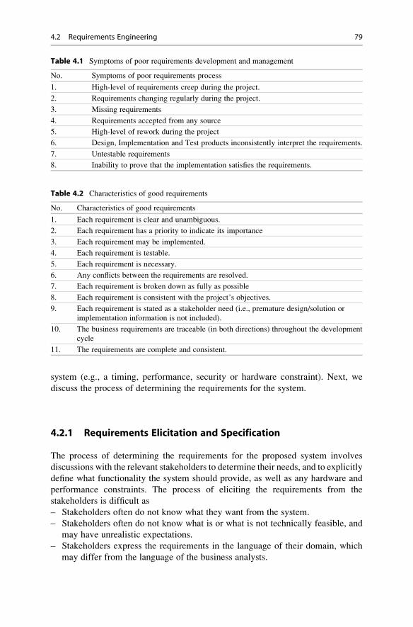
system (e.g., a timing, performance, security or hardware constraint). Next, we
discuss the process of determining the requirements for the system.
4.2.1 Requirements Elicitation and Specification
The process of determining the requirements for the proposed system involves
discussions with the relevant stakeholders to determine their needs, and to explicitly
define what functionality the system should provide, as well as any hardware and
performance constraints. The process of eliciting the requirements from the
stakeholders is difficult as
– Stakeholders often do not know what they want from the system.
– Stakeholders often do not know what is or what is not technically feasible, and
may have unrealistic expectations.
– Stakeholders express the requirements in the language of their domain, which
may differ from the language of the business analysts.
Table 4.1 Symptoms of poor requirements development and management
No. Symptoms of poor requirements process
1. High-level of requirements creep during the project.
2. Requirements changing regularly during the project.
3. Missing requirements
4. Requirements accepted from any source
5. High-level of rework during the project
6. Design, Implementation and Test products inconsistently interpret the requirements.
7. Untestable requirements
8. Inability to prove that the implementation satisfies the requirements.
Table 4.2 Characteristics of good requirements
No. Characteristics of good requirements
1. Each requirement is clear and unambiguous.
2. Each requirement has a priority to indicate its importance
3. Each requirement may be implemented.
4. Each requirement is testable.
5. Each requirement is necessary.
6. Any conflicts between the requirements are resolved.
7. Each requirement is broken down as fully as possible
8. Each requirement is consistent with the project’s objectives.
9. Each requirement is stated as a stakeholder need (i.e., premature design/solution or
implementation information is not included).
10. The business requirements are traceable (in both directions) throughout the development
cycle
11. The requirements are complete and consistent.
4.2 Requirements Engineering 79

– Different stakeholders may want different things from the system resulting in
conflicts that need to be resolved.
The project manager/business analyst and relevant stakeholders will conduct a
brainstorming session to define the high level requirements for the proposed system
(or modification to an existing system). Further requirements workshops will
review and analyse the draft requirements, and identify all further relevant infor-
mation for the proposed system. The workshops involve interviews with the
relevant stakeholders to elicit the actual requirements for the proposed system
from the stakeholders.
Prototyping helps to identify gaps and misunderstandings in the definition of the
requirements. The prototype is an early working version of the system, and it is used
to give the users a flavour of what the working system will look like, and its
evaluation by the stakeholders helps in clarifying the requirements. The prototype
may be thrown away at the end of prototyping, or it may be re-used in the
development of the system. It involves:
– Define prototype objectives
– Decide which functional requirements will be prototyped
– Develop the prototype
– Evaluate the prototype
The project manager (or a business analyst) will facilitate the requirements
workshop, and the requirements gathered are then consolidated into a coherent
set of requirements to form the first draft of the user requirements. Following the
initial workshop, the project manager/business analyst prepares a draft of the
detailed requirements, and sends the document to the participants for comments.
Further requirements workshops are held to discuss and analyse the draft
requirements to ensure that they meet the needs of the stakeholders, and this process
continues until all participants are in agreement with the user requirements. In some
cases, the requirements may already be defined and documented by the customer.
The requirements workshops involve a brainstorming session with the attendees,
and this allows the users to discuss their needs and the requirements for the
proposed system. The requirements workshops allow the proposed requirements
to be discussed, analysed and prioritized. Any conflicts in the requirements are
identified and resolved. The requirements document is updated accordingly with
the agreed set of user requirements.
The project manager/business analyst may use a checklist to determine that the
requirements have been fully specified, and to verify that every requirement
specified is actually necessary. The final version of the user requirements document
is circulated to all participants for their final review and approval.
Once the user requirements have been agreed by all stakeholders the work on the
system requirements commences, and the business analyst expands the user
requirements into more specific and detailed system requirements. Further system
requirements workshops are conducted with the relevant stakeholders until the
system requirements are approved.
80 4 Requirements, Design and Development

The requirements for a system are generally documented in a natural language
such as “English”. Natural language is inherently ambiguous, and therefore care
needs to be taken to ensure that the definition is precise and unambiguous.
The ambiguity of natural language has led to interest in precise notations to
express requirements unambiguously. These include the formal specification
notations such as Z or VDM that are often employed in the safety critical or security
critical fields. The advantage of these mathematical languages is that they are
precise and amenable to proof, and mathematical analysis may be employed in a
sense to debug1 the requirements. This provides increased confidence in the cor-
rectness and validity of the requirements. However, these notations are perceived as
being difficult to use by industrialists, and they are not widely employed at this
time. Formal methods are discussed in Chap. 17.
Other notations to express the requirements include the visual modelling lan-
guage UML [32] which has become popular in recent years. UML is discussed in
Chap. 19.
4.2.2 Requirements Analysis
The requirements are analysed to ensure that they are technically feasible and to
identify any conflicts between them. The resolution of any conflicts is through
negotiations with the stakeholders. The requirements are prioritized to define the
importance of each requirement, and some development models implement the most
important requirements first. Requirements analysis is an iterative process with
feedback going back to the stakeholders in the requirements elicitation process.
The workshops will verify that the system requirements are valid with respect to
the user requirements, and technical workshops will need to be conducted to
determine the appropriate approach to their implementation.
4.2.3 Requirements Verification and Validation
The difference between requirements validation and verification is illustrated by the
phrase “Building the right thing” vs. “building it right”. In other words validation isconcerned with ensuring that the correct requirements are being implemented,
whereas verification is concerned with ensuring that the requirements are being
implemented correctly.
The stakeholders validate the requirements to ensure that the defined
requirements are actually those desired. This may involve several reviews of the
requirements (and prototype) by the stakeholders, with updates made by the author
until all stakeholders are ready to approve the requirements of the system.
1 Essentially, the mathematical language provides the facility to prove that certain properties are
true of the specification, and that certain undesirable properties are false in the specification.
4.2 Requirements Engineering 81

The validation of the requirements will ensure that the requirements are complete,
consistent, and realizable and reflect the needs of the customer. The final validation
step is the user acceptance testing, and this is performed by the customer to confirm
that the completed system fully meets user requirements. The lifecycle model
employed determines the verification and validation activities to be conducted during
the project, with models such as joint application development (JAD) and Agile
involving a high-level of customer involvement.
Requirements verification is concerned with ensuring that the system as built
(from design, to development, to testing) properly implements the defined
requirements. A traceability matrix shows how the requirements are implemented
and tested, and may be employed for requirements verification.
4.2.4 Managing Changes to Requirements
A change request is a stakeholder request for a change to the scope of the project,
and it may arise at any time during the project. It is essential that the impacts of a
change request on schedule, effort, budget and technical areas are fully considered
prior to its authorisation.
Once the system requirements have been approved, any proposed changes to the
requirements are subject to formal change control. Change request are considered
by the change control board (CCB), who make an informed decision to authorise or
reject the request based on its impacts.
The need to change the requirements may be due to business or regulatory
changes, or to a customer need becoming apparent at a late stage of the project
when the system is nearing completion. The impacts of the change request (e.g.,
technical, cost and schedule) need to be carefully considered, as a change
introduces new risks to the project, and may adversely affect cost, schedule and
quality. The activities involved in managing change requests are summarised in
Table 4.3.
Following the approval of a change request the affected documents such as the
system requirements, the design, and software modules are modified. Testing is
carried out to verify that the changes have been implemented correctly.
4.2.5 Requirements Traceability
The objective of requirement traceability is to verify that all of the requirements for
the project have been implemented and tested. One way to do this is to consider
each requirement number and to go through every part of the design document to
find where the requirement is being implemented in the design, and similarly to go
through the test documents and find any reference to the requirement number to
show where it is being tested. This would demonstrate that the particular require-
ment number has been implemented and tested.
82 4 Requirements, Design and Development

A more effective mechanism to do this is to employ a traceability matrix, which
may be employed to map the user requirements to the system requirements; the
system requirements to the design; the design to the unit test cases; the system test
cases; and the UAT test cases. That is, traceability is defined through the project
lifecycle, and the matrix provides details of how the requirements have been
implemented and tested.
The traceability of the requirements is bi-directional, and the traceability matrix
may be maintained as a separate document, or as part of the requirements docu-
ment. The basic idea is that a mapping between the requirement numbers and
sections of the design or test plan is defined, and this provides confidence that all
of the requirements have been implemented and tested.
Requirements may be numbered and a single requirement number may map on
to several sections of the design or to several test cases: i.e., the mapping may be
one to many. The traceability matrix (Table 4.4) provides the mapping between
individual requirement numbers, and the sections in the design or test plan
corresponding to the particular requirement number.
This mapping will typically be one to many: i.e., a single requirement number
will typically be implemented in several design sections, and verified by several test
cases. The traceability matrix will be employed to demonstrate that all of the
requirements have been implemented and tested.
It is essential to keep the traceability matrix up to date during the project, and
following changes to the requirements. The traceability matrix is useful as a tool
whenever there are changes to the requirements as it allows the impacts of the
change on the other requirements (and other project deliverables) to be easily
determined.
Table 4.3 Managing change requests
Activity Change request
Log change
request
The change request is logged and a unique reference number and severity
assigned.
Assess impact The cost, schedule, technical and quality impacts are determined and the risks
identified.
Decision The CCB authorises or rejects the change request.
Implement
solution
The affected project documents and software modules are identified, and
modified accordingly.
Verify solution Testing (Unit, System and UAT) are employed to verify the correctness of the
solution.
Close CR The change request is closed.
Table 4.4 Sample trace
matrixRequirement no. Sections in design Test cases in test plan
Rl.l D1.4, D1.5, D3.2 T1.2, T1.7
R1.2 D1.8, D8.3 T1.4
R1.3 D2.2 T1.3
R1.50 D20.1, D30.4 T20.1 T24.2
4.2 Requirements Engineering 83

4.3 Architecture Design
The design of the system consists of engineering activities to describe the
architecture model or structure of the system that will satisfy the functional and
non-functional requirements, as well as the design of the individual programs todescribe the algorithms and functions required to implement the system
requirements. Design is a creative process concerned with how the system will
be organized, and the architecture design is often presented as a set of interacting
components. The design activities include architecture design, interface design,
component design, algorithm design, and data structure design. There are often
several possible design solutions for a particular system, and the designer will need
to choose the most appropriate design of the system.
The architectural model of the system is an abstract visual representation of the
system, and it is often presented as a set of boxes or block diagrams. The major
components of the system and their interactions are identified, and each box
represents a component with the architecture showing all the components and
their connections. A box within a box represents a sub-component, and arrows
are used to represent the flow of data between the components. This abstract
description of the system provides a high-level view of the system, and is an
effective way to facilitate discussion about the system design with the relevant
stakeholders.
The views of C.A.R. Hoare on software design are interesting (Fig. 4.1). He
states that there are two ways of constructing a software design.
One way is to make it so simple that there are obviously no deficiencies.
The other way is to make it so complex that there are no obvious deficiencies.
He argues that the first method is far more difficult to achieve, and that it requires
skill and insight.
The starting point in design is always the problem domain, and it is essential that
the problem to be solved is understood from a number of different viewpoints. A
number of potential solutions may then be identified, and each potential solution is
evaluated. This leads to the chosen solution which may, for example, be the
simplest and least costly.
Design is an iterative process and the goal is to describe the system architecture
that will satisfy the functional and non-functional requirements. It involves describ-
ing the system at a number of different levels of abstraction, with the designer
starting off with an informal picture of the design that is then refined by adding
more information.
Parnas’s ideas on design have been quite influential (Fig. 4.2), and his 1972
paper “On the criteria to be used in decomposing systems into modules” [52] is a
classic in software engineering. He introduced the revolutionary information hidingprinciple, which allows software to be designed in a way to deal with change. Amodule is characterized by its knowledge of a design decision (secret) that it hidesfrom all other modules. Every information-hiding module has an interface that
provides the only means to access the services provided by the modules. The
84 4 Requirements, Design and Development

interface hides the module’s implementation. Information hiding is used in object-
oriented programming. Parnas argues in his 1972 paper that:
It is almost always incorrect to begin the decomposition of a system into modules on the
basis of a flowchart. We propose instead that one begins with a list of difficult design
decisions or design decisions which are likely to change. Each module is then designed to
hide such a decision from the others
The design may be specified in various ways such as graphical notations that
display the relationships between the various components making up the design.
The notation may include block diagrams, flow charts, or various UML diagrams
such as sequence diagrams, state charts, and so on. The design of programs may
employ pseudo code to specify the algorithms as well as the data structures that are
the basis for implementation. Natural language is often employed to express
information that cannot be expressed formally. The design activities include:
– Architecture Design of system (with all sub-systems)
– Abstract specification of each sub-system
– Interface Design (for each subsystem)
– Component Design
Fig. 4.1 C.A.R. Hoare
(Public domain)
Fig. 4.2 David Parnas
(Public domain)
4.3 Architecture Design 85

– Data Structure Design
– Algorithm Design
The quality of the software architecture directly impacts the robustness, perfor-
mance and maintainability of the system. A good software architecture will manage
the inherent complexity of the system, and ensures a solid performance of the
implemented system, with safety, security, availability and maintainability require-
ments properly addressed.
There is a need to present multiple views of the system architecture such as how
the system is decomposed into modules, how the run-time processes interact, how
the hardware is distributed across the processors in the system. These views may
include [61] those given in Table 4.5.
The process view could be described by data-flow diagrams (part of the SSADM
method) which show the flow of data through a system. UML is a popular design
method which gives several views of the architecture of the system. It is essential
validate the design with respect to the system requirements.
4.4 Design and Development
The design of the system consists of engineering activities to describe the
components of the system as well as the algorithms and functions required to
implement the system requirements. Design and development are closely related
and are concerned with developing an executable software system.
Functional design involves starting with a high-level view of the system and
refining it into a more detailed design. The system state is centralized and shared
between the functions operating on that state.
Object-oriented design has become popular in recent years and is based on the
concept of information hiding developed by Parnas [52]. The system is viewed as a
collection of objects rather than functions, with each object managing its own state
information. The system state is decentralized and an object is a member of an
object class. The definition of a class includes attributes and operations on class
members, and these may be inherited from super classes. Objects communicate by
exchanging messages.
Table 4.5 Views of system architecture
View Description
Logical This view shows the key abstractions in the system as objects or object classes
Process view This view shows how the system is composed of interacting processes at
run-time.
Development
view
This view shows how the software is decomposed into modules/components for
development.
Physical view This view shows the system hardware and how the software components are
distributed across the system.
86 4 Requirements, Design and Development

Software design and development are closely linked, and often proceed in
parallel. Software design is the creative process that identifies the software
components and their relationships, whereas software development is concerned
with the implementation of the design in some programming language. The choice
of language reflects the problem domain, and may be an object-oriented language
such as C++ or Java, or a procedural language such as C or FORTRAN. It is important
that the software code is subject to a peer review to ensure that it is of high-quality,
and that it is a valid implementation of the requirements and design. The coding
standards for the language will also need to be followed, as this assists in the
maintainability of the code.
Software reuse has become topical in recent years, and today many organizations
approach to development includes software reuse. The advantages of software reuse
are that it potentially improves productivity, and delivers higher quality software.
Open source development is a modern approach to software development in which
the source code is published, and software developers from around the world
volunteer to participate in the software development process. The idea is that the
source code is not proprietary, and that it should be available for software developers
to use and modify as they wish.Customized-off-the-shelf software (COTS) is software(or a system) that may be purchased off-the-shelf, and adapted to the user’s
requirements. The reader is referred to the classic text in software engineering [61]
for a more detailed explanation of the design and development activities.
4.5 Review Questions
1. What is the difference between a functional and non-functional
requirement?
2. What is the difference between requirements verification and validation?
3. How are requirement elicited from the customer?
4. Discuss the difference between architecture design and detailed design.
5. How are changes to the requirements managed?
6. What is the purpose of requirements traceability?
7. Explain the differences between COTS, software reuse, and open source
software.
4.6 Summary
The success of business is highly influenced by software, and companies may
develop their own software internally, or they may acquire software solutions off-
the-shelf or from bespoke software development. Cost is a key driver in most
organizations and it is essential that software is produced as cheaply and efficiently
as possible, and that waste is reduced or eliminated in the software development
4.6 Summary 87

process. Companies need to produce software that is better, faster and cheaper thantheir competitors in order to survive in the market place.
The user requirements specify what the customer wants and define what thesoftware system is required to do, as distinct from how this is to be done. The
requirements are the foundation for the system, and it is essential that they are
correct and reflect the needs of the customer.
Often, the initial requirements for a project arise due to a particular problem that
the business or customer needs to solve. The first step is to determine the scope of
work and the actual requirements for the project, and whether the project is feasible.
The user requirements are determined from discussions with the customer to
determine their actual needs, and they are then refined into the system requirements.
The software design of the system is concerned with the architecture of the
system, as well as activities to describe the algorithms and functions required to
implement the system requirements. It is a creative process concerned with how the
system will be implemented, and it may include hardware as well as the various
software modules and their interfaces.
The software development is concerned with the actual implementation of the
design, and the implementation is in some programming language such as C++ or
Java. The software may be developed internally or it may be outsourced to another
company, or a solution may be purchased off-the-shelf. It is essential that the design
is valid with respect to the requirements, and that the implemented system is valid
with respect to the design.
88 4 Requirements, Design and Development

Configuration Management 5
Key Topics
Configuration Item
Baseline
Configuration Management System
Change Control
Change Control Board
Configuration Management Audits
File Naming Conventions
Version Control
5.1 Introduction
Software configuration management is concerned with identifying the configuration
items of a system; controlling changes to them; and maintaining integrity and
traceability. The configuration items are generally documents in the early part of
the development lifecycle, whereas the focus is on source code control management
and software release management in the later parts of development. Configuration
management involves:
– Identifying what needs to be controlled
– Ensuring those items are accurately defined and documented
– Ensuring that changes are made in a controlled manner
– Ensuring that the correct version of a work product is being used
– Determining the status of a configuration item at any time
– Ensuring adherence to company standards
– Planning builds and releases
G. O’Regan, Introduction to Software Quality, Undergraduate Topicsin Computer Science, DOI 10.1007/978-3-319-06106-1_5,# Springer International Publishing Switzerland 2014
89

It allows the orderly development of software, and it ensures that the impacts of
proposed changes are considered prior to authorization. It ensures that releases are
planned and that only authorized changes to the software are made. The integrity of
the system is maintained and the constituents of the software system and their
version numbers are known at all times.
Effective configuration management allows questions such as in Table 5.1 to be
easily answered.
The symptoms of poor configuration management include corrected defects that
suddenly begin to reappear; difficulty in or failure to locate the latest version of
source code; or failure to determine the source code that corresponds to a software
release. Therefore, it is important to employ sound configuration management
practices to enable high-quality software to be consistently produced. Poor config-
uration management practices lead to quality problems resulting in a loss of the
credibility and reputation of a company. Several symptoms of poor configuration
management practices are listed in Table 5.2.
Configuration management involves identifying the configuration items to be
controlled, and systematically controlling change to them, in order to maintain the
integrity and traceability of the configuration throughout the lifecycle. There is a
need to manage and control changes to documents and source code, including the
project plan, the requirements document, design documents, code, and test plans.
A key concept in configuration management is that of a “baseline”, which is a setof work products that have been formally reviewed and agreed upon, and serves asthe foundation for future development work.
A baseline can only be changed through a formal change control procedure
which leads to a new baseline. It provides a stable basis for the continuing evolution
of the configuration items, and all approved changes move forward from the current
baseline leading to the creation of a new baseline. The CCB authorizes the release
of baselines, and the content of each baseline is documented. All configuration
items must be approved before they are entered into the released baselines.
Therefore, it is necessary to identify the configuration items that need to be placed
under formal change control, and to maintain a history of the changes made to the
baseline. There are four key parts to software configuration management (Table 5.3).
Table 5.1 Features of good configuration management
Features of good configuration management
What is the correct version of the software module to be updated?
Where can I get a copy of R4.7 of Software System X?
What versions of the Software System X are installed at the various customer sites?
What changes have been introduced in the new release of software (version R4.8 from the previous
release of R4.7)?
What version of the Design document corresponds to software system version R3.5?
What customers use R3.5 of the software system?
Are we certain that no undocumented or unapproved changes have been included in released
versions of the software?
90 5 Configuration Management

A typical software release, e.g., in the telecommunications domain, consists of
incremental development where the software to be released consists of a number of
release builds where each build initially consists of new functionality, and the later
builds consists of fix releases.
Software configuration management is planned for the project and each project
will typically have a build plan which will detail the planned delivery of function-
ality and fix release to the project (Table 5.4).
Each of the R. 1.0.O.k are termed release builds and they consist of functionality
and fixes to problems. The content of each release build is known; i.e., the project
team and manager will target specific functionality and fixes for each build, and the
actual content of the particular release baseline is documented. Each release build
Table 5.2 Symptoms of poor configuration management
Symptoms of poor configuration management
Defects corrected suddenly begin to re-appear
Cannot find latest version of source code
Unable to match source code and object code
Wrong version of software sent to the customer
Wrong code tested
Cannot replicate previously released code
Simultaneous changes to same source component by multiple developers with some changes lost
Table 5.3 Software configuration management activities
Area Description
Configuration
Identification
This requires identifying the configuration items to be controlled, and
implementing a sound configuration management system, including a
repository where documents and source code are placed under controlled
access. It includes a mechanism for releasing documents or code, a naming
convention and version numbering system for documents and code, and
baseline/release planning. The version and status of each configuration
item should be known.
Configuration
Control
This involves tracking and controlling change requests, and controlling
changes to the configuration items. Any changes to the work products are
controlled, and authorized by a change control board or similar mechanism.
Problems or defects reported by the test groups or customer are analysed,
and any changes made are subject to change control. The version of the
work product is known, and the constituents of a particular release are
known and controlled. The previous versions of releases can be recreated
as the source code constituents are fully known.
Configuration
Auditing
This includes audits of the baselines to verify integrity of the baseline and
audits of the configuration management system itself and verification that
standards and procedures are followed. The results of the audits are
communicated to the affected groups and corrective action taken.
Status Accounting This involves data collection and report generation. These reports include
the software baseline status, the summary of changes to the software
baseline, problem report summaries, and change request summaries
5.1 Introduction 91

can be replicated, as the version of source code to create the build is known and the
source code is under control management.
There are various tools employed for software configuration management
activities, and these include well-known tools such as Clearcase, PVCS, Visual
Source Safe (VSS) for source code control management. The PV tracker tool and
Clearquest may be used for tracking defects and change requests. A defect tracking
tool will list all of the open defects against the software, and a defect may require
several change requests to correct the software, as a problem may affect different
parts of the software product as well as different versions of the product, and a
change request may be necessary for each part. The tool will generally link the
change requests to the problem report. The current status of the problem report can
be determined, and the targeted release build for the problem identified.
The CMMI provides guidance on practices to be implemented for sound config-
uration management (Table 5.5).
The CMMI requirements are concerned with establishing a configuration man-
agement system; identifying the work products that need to be subject to change
control; controlling changes to these work products over time; controlling releases
of work products; creating baselines; maintaining the integrity of baselines;
providing accurate configuration data to stakeholders; recording and reporting the
status of configuration items and change requests; and verifying the correctness and
completeness of configuration items with configuration audits. We shall discuss the
key parts of configuration management in the following Sections.
Table 5.4 Build plan Release baseline Contents
R 1.0.0.0 F4, F5, F7
R. 1.0.0.1 F1, F2, F6 + fixes
R. 1.0.0.2 F3 + fixes
R. 1.0.0.3 F8 + fixes (functionality freeze)
R. 1.0.0.4 Fixes
R. 1.0.0.5 Fixes
R. 1.0.0.6 Official release
Table 5.5 CMMI requirements for configuration management
Specific goal Specific practice Description of specific practice/goal
SG 1 Establish baselines
SP 1.1 Identify configuration items
SP 1.2 Establish a configuration management system
SP 1.3 Create or release baselines
SG 2 Track and control changes
SP 2.1 Track change requests
SP 2.2 Control configuration items
SG 3 Establish integrity
SP 3.1 Establish configuration management records
SP 3.2 Perform configuration audits
92 5 Configuration Management

5.2 Configuration Management System
The configuration management system enables the controlled evolution of the
documents and the software modules produced during the project. It includes
– Configuration management planning.
– A document repository with check in/check out features
– A source code repository with check in/check out features
– A configuration manager (may be a part time role)
– File naming convention for documents and source code.
– Project directory structure
– Version Numbering System for documents
– Standard templates for documents
– Facility to create a baseline
– A release procedure
– A group (change control board) to manage changes to baseline
– A change control procedure
– Configuration management audits to verify integrity of baseline
5.2.1 Identify Configuration Items
The configuration items are the work products to be placed under configuration
management control, and they include project documents, source code and data
files. They may also include compilers as well as any supporting tools employed in
the project.
The project documentation will typically include project plans; the business
requirements document; the system specification; the architecture and technical
design documents; the test plans, etc.
The items to be placed under configuration management control are identified
and documented early in the project lifecycle. Each configuration item needs to be
uniquely identified and controlled. This may be done with a naming convention for
the project deliverables and source code, and applying it consistently. For example,
a simple approach is to employ mnemonics labels and version numbers to uniquely
identify project deliverables. For example, a business requirements specification for
project 005 in the Finance business area may be represented simply by:
FIN 005 BRS
5.2.2 Document Control Management
The project documents are stored in a document repository using a configuration
management tool such as PVCS or VSS. For consistency, a standard directory
structure is often employed for projects, as this makes it easier to locate particular
5.2 Configuration Management System 93

configuration items. A single repository may be employed for both documents and
software code, or a separate repository for each.
Clearly, it is undesirable for two individuals to modify the same document at the
same time, and the document repository will include check in/check out procedures.The document must be checked out prior to its modification, and once it is checked
out it may not be modified by another until it is checked back in. An audit trail of all
modifications made to a particular document is maintained, including who made the
change, the date the change was made, and the rationale for the change.
5.2.2.1 Version Numbering of DocumentsA simple version numbering system may be employed to record the versions of
documents: e.g., v0.1, v0.2, v0.3 is often used for draft documents, with version
v1.0 being the first approved version of the document. Each time a document is
modified its version number is incremented, and the document history records the
reasons for modification.
– V0.1 Initial draft of document
– V0.x Revised draft (x> 0)
– V1.0 Approved baseline version
– V1.x Approved minor revision (x> 0)
– Vn.0 Approved major revision (n> 1)
– Vn.x Approved minor revision (x> 0, n >1)
The configuration management system will provide records of the configuration
management activities as well as the status of the configuration items and the
status of the change requests. The revision history of the configuration items will
be maintained.
5.2.3 Source Code Control Management
The source code and data files are stored in a source code repository using a tool
such as PVCS, VSS or Clearcase, and the repository provides an audit trail of all the
changes made to the source code. An item must first be checked out for modifica-
tion, the changes are made, and it is then checked back in to the repository. The
source code management system provides security and control of the configuration
items, and the procedures include:
– Access controls
– Checking in/out configuration items
– Merging and Branching
– Labels
– Reporting
This ensures that the integrity of the work product is preserved, and prevents
more than one person from altering the work product at the same time.
94 5 Configuration Management

5.2.4 Configuration Management Plan
A software configuration management plan is prepared early in the project, and
defines the configuration management activities for the project. It may be a section
of the overall project plan or a separate plan. It will detail the items to be placed under
configuration management control, the standards for naming configuration items, the
version numbering system, as well as version control and release management.1 The
configuration management plan is placed under configuration management control.
The contents of each software release need to be documented as well as
installation and rollback instructions. It will detail the requirements and change
requests implemented, as well as the defects corrected and the version of the new
release. A list will be maintained customer sites of where the release has been
installed. All software releases are tested appropriately prior to their approval. The
CM plan will include:
– Roles and responsibilities
– Configuration Items
– Naming Conventions
– Version Control
– Filing Structure for project
The stakeholders and roles involved are identified and documented in the CM
plan. Often, the role of a software configuration manager is employed, and this may
be a full or part time role2 depending on the size of the organization and projects.
The CM manager ensures that the configuration management activities are carried
out correctly, and will conduct and report the results of the CM audits.
5.3 Change Control
A change request database3 is set up to record requests for changes during the
project. The change requests are documented and considered by the change control
board (CCB). The CCB may just consist of the project manager and the system
owner for small projects. The impacts and risks of the proposed change are
considered, and the CCB rejects or approves the request. The impacts may be on
the schedule and budget, as well technical. It is important to keep change to a
minimum at the later stages of the project in order to reduce risks to quality.
Figure 5.1 describes a simple process for raising a change request; performing an
impact assessment; deciding on whether to approve or reject the change request;
and proceeding with implementation (where applicable).
The results of the CCB review of each change request (including the rationale of
the decision made) will be recorded. Change requests and problem reports for all
1 These may be defined in a Configuration Management procedure and referenced in the CM plan.2 The project manager may perform the CM manager role for small organizations and projects.3 This may just be a simple Excel spread sheet or a sophisticated tool.
5.3 Change Control 95

Change Request
Log CR1. Log in Issue Log
2. Complete Change Request Form
1. Logged CR2. CR form completed
Assess Impact of Change
1. Cost / schedule impacts2. Technical Impacts
3. Deliverables affected
Impact recorded (on CR Form)
Approve CR 1. Update CR Form 2. Update Issue Log
Updated CR Form & Issue Log.
Y
ApproveCR?
No
Closed CR
Close CR1. Update CR Form2. Update Issue Log
Implement Changes
Fig. 5.1 Simple process map for change requests
96 5 Configuration Management

configuration items are recorded and analysed, reviewed, approved (or rejected)
and tracked to closure.
A sample configuration management process map is detailed in Fig. 5.2, and it
shows the process for updates to configuration information following an approved
change request. The deliverable is checked out of the repository; modifications are
made and the changes approved; configuration information is updated and the deliv-
erable is checked back into the repository.
Change Approved
Modify deliverable1. Check out of repository
2. Make Changes3. Review & update
4. Update document history
5. Update Version Number
NewDeliverable ?
N
Create deliverable1. Create deliverable
(using template)2. Review & update
4. Update document history
5. Update Version Number6. Assign Document ID
Y
Created deliverable Modified deliverable
Approve Deliverable ?
Approve Deliverable ?
N N
Approved deliverable
Check in deliverable1. Check into repository
2. Record comments
Checked in deliverable
Fig. 5.2 Simple process map for configuration management
5.3 Change Control 97

5.4 Configuration Management Audits
Configuration management audits are conducted during the project to verify that
the configuration is consistent and complete. Every project should have at least one
configuration audit, and the objective is to verify the completeness and correctness
of the configuration system for the project. The audit will check that the records
correctly identify the configuration, and that the configuration management standards
and procedures have been followed. Table 5.6 presents a sample checklist.
There may also be a librarian role to set up the filing structure for the project, orthe configuration manager may perform this role. The project manager assigns
responsibilities for performing configuration management activities. All involved
in the process receive appropriate training on the process.
5.5 Review Questions
1. What is software configuration management?
2. What is change control?
3. What is a baseline?
4. Explain source code control management.
5. Explain document control management.
6. What is a configuration management audit and explain how it differs from
a standard audit?
7. Describe the role of the configuration manager and librarian.
8. What is a baseline?
Table 5.6 Sample configuration management audit checklist
No. Item to check
1. Is the Directory Structure set up for the project?
2. Are the configuration items identified and listed?
3. Have the latest versions of the templates been used?
4. Is a unique document Id employed for each document?
5. Is the standard version numbering system followed for the project?
6. Are all versions of documents and software modules in the document/source code repository?
7. Is the Configuration Management plan up to date?
8. Are the roles defined in the Configuration Management Plan performing their assigned
responsibilities?
9. Are changes to the approved documents formally controlled?
10. Is the version number of a document incremented following an agreed change to an approved
document?
11. Is there a change control board set up to approve change requests?
12. Is there a record of which releases are installed at the various customer sites?
13. Are all documents/software modules produced by vendors under appropriate configuration
management control?
98 5 Configuration Management

5.6 Summary
Software configuration management is concerned with the orderly development and
evolution of the software. It involves identifying the configuration items that are
subject to change control, controlling changes to them, and maintaining integrity
and traceability. The configuration items are generally documents in the early part
of the development lifecycle, whereas the focus is on source code control manage-
ment and software release management in the later parts of development.
The company standards need to be adhered to, and the correct version of a work
product should be known at all time. There is a need for a document and source code
repository, which has access controls, checking in and checking out procedures; and
labelling of releases.
A project will have a configuration management plan, and the configuration
manager role is responsible for ensuring that the configuration management activities
are carried out correctly. Configuration audits will be conducted to verify that the CM
activities have been carried out correctly.
Configuration management ensures that the impacts of proposed changes are
considered prior to authorization. It ensures that releases are planned and that only
authorized changes to the software are made. The integrity of the system is
maintained, and the constituents of the software system and their version numbers
are known at all times.
5.6 Summary 99

Software Inspections 6
Key Topics
Fagan Inspection
Gilb Inspections
Economic Benefits of Inspection
Inspection Guides
Entry and Exit Criteria
Informal Reviews
Prince 2 Quality Review
Agile Reviews
6.1 Introduction
The objective of software inspections is to build quality into the software product,
rather than adding quality later. There is clear evidence that the cost of correction of
a defect increases the later that it is detected, and it is therefore more cost effective
to build quality in rather than adding it later in the development cycle. Software
inspections are an effective way of doing this.
There are several approaches to software inspections, and these vary in the level
of formality employed. A simple informal approach consists of a walkthrough of
the document or code by an individual other than the author. The meeting usually
takes place at the author’s desk or in a meeting room, and the reviewer and author
discuss the document or code informally.
There are formal software inspection methodologies such as the well-known
Fagan inspection methodology [20] and the Gilb methodology [24]. These metho-
dologies include pre-inspection activity, an inspection meeting, and post-inspection
G. O’Regan, Introduction to Software Quality, Undergraduate Topicsin Computer Science, DOI 10.1007/978-3-319-06106-1_6,# Springer International Publishing Switzerland 2014
101

activity. Several inspection roles are typically employed, including an author role, aninspector role, a tester role, and a moderator role.
The Fagan inspection methodology was developed by Michael Fagan (Fig. 6.1)
at IBM in the mid-1970s, and the Gilb methodology was developed by Tom Gilb.
The formality of the inspection methodology used by an organization is dependent
on its type of business. The impact of a defect may have a major adverse effect on
the customer’s business: for example, an incorrect one-line change to telecoms
software could create a major telecommunications outage and major disruption to
customers. There may be financial impacts, as the service level agreement details
the service level that will be provided, and the compensation given for service
disruption. Consequently, a telecommunications company needs to ensure that its
software is fit for purpose, and a formal inspection process tends to be employed.
This means that requirement documents, high-level and detailed design documents,
and code are inspected, and generally inspections are explicitly planned in the
project schedule.
An organization will need to devise an inspection process which is suitable for
its particular needs. The level of formality is influenced by its business, its culture, and
the potential impact of a software defect on its customers. It may adopt a formal
approach such as the Fagan or Gilb methodology, or it may devise a less formal
process tailored to its needs. It may not be possible to have all of the participants
present in a room, and participation by conference call or video linkmay be employed.
A formal inspection process may not suit some organization cultures, and an informal
approach such as a structured walkthrough may be the adopted approach.
Software inspections play an important role in building quality into each phase,
and in ensuring that the quality of the delivered product is good. The quality of the
delivered software product is only as good as the quality at the end each phase, and
therefore a phase should be exited only when the desired quality has been achieved.
The effectiveness of an inspection is influenced by the expertise of the inspectors,
adequate preparation, the speed of the inspection, and compliance to the inspection
process. The inspection methodology provides guidelines on the inspection and
Fig. 6.1 Michael Fagan
102 6 Software Inspections
preparation rates for an inspection, and guidelines on the entry and exit criteria for
an inspection.
There are typically at least two roles in the inspection methodology. These
include the author role and the inspector role. Themoderator, tester, and the readerrole may also be present in the methodology.
The next section describes the benefits of software inspections, and this is
followed by a discussion of a simple review methodology where the reviewers
send comments directly to the author. Then, a slightly more formal inspection
process is described, and finally the Fagan inspection process is described in detail.
6.2 Economic Benefits of Software Inspections
A software inspection program has tangible benefits in terms of productivity,
quality, time to market, and customer satisfaction. For example, IBM Houston
employed software inspections for the Space Shuttle missions: 85 % of the defects
were found by inspections and 15 % were found by testing. There were no defects
found on the space missions, and about two million lines of computer software were
employed. IBM, North Harbour in the UK quoted a 9 % increase in productivity
with 93 % of defects found by software inspections.
Software inspections are useful for educating new employees on the product,
and on the standards and procedures used in the organization. They ensure that
knowledge is shared among the employees, rather than understood by just one
individual. Inspections improve software productivity, as less time is spent in
correcting defective software.
The cost of correction of a defect increases the later that it is identified in the
lifecycle. Boehm [7] states that the cost of correction of a requirements defectidentified in the field is over 40 times more expensive than if it were detected at therequirements phase, and so it is most economical to detect and fix the defect in
phase. The cost of correction of a requirements defect identified at the customer site
includes the cost of correcting the requirements, the cost of design, coding, unit
testing, system testing, and regression testing. It may be necessary to send an
engineer on site to fix the problem, and there may be hidden costs in the negative
perception of the company with a subsequent loss of sales. There is a powerful
argument to identify defects as early as possible, and software inspections are a cost
effective way to achieve this.
There are various estimates of the cost of poor quality (COPQ) in an organiza-
tion (Fig. 1.9), and estimates suggest that it may be 20–40 % of sales. The exact
calculation may be determined by a time sheet accountancy system, which details
the cost of internal and external failure, and the cost of appraisal and prevention.
The return on investment from an introduction of software inspections may be
calculated, and the evidence available suggests that they are a cost-effective way of
improving quality and productivity.
6.2 Economic Benefits of Software Inspections 103

6.3 Informal Reviews
This type of review involves reviewers sending comments directly to the author,
and there is no actual review meeting. It is not as effective as the Fagan inspection
process, but it helps in identifying some defects in the work products.
The author is responsible for making sure that the review happens, and advises
the participants that comments are due by a certain date. The author analyses the
comments received, makes the required changes, and circulates the document for
approval. The activities involved are described in Table 6.1.
Comment: The informal review process may help to improve quality in an organi-
zation. It is dependent on the participants adequately reviewing the deliverable andsending comments to the author. The author can only request the reviewer to sendcomments. There is no independent monitoring of the author to ensure that thereview actually happens and is effective, and that comments are requested,received, and implemented.
6.4 Structured Walkthrough
A structured walkthrough is a peer review in which the author of a deliverable (e.g.,
a project document or actual code) brings one or more reviewers through the
deliverable. The objective is to get feedback from the reviewers on the quality of
the document or code, and to familiarize the review audience with the author’s
work. The walkthrough includes several roles namely the review leader (usuallythe author), the author, the scribe (may be the author) and the review audience(Table 6.2).
Table 6.1 Informal review
Step Description
1. The author circulates the deliverable (either physically or electronically) to the review
audience.
2. The author advises the review audience of the due date for comments
3. The due date for comments is typically 1 week or longer.
4. The author checks that all comments have been received by the due date
5. Any reviewers who have not provided feedback are contacted by the author, and comments
are requested.
6. The author analyses all comments and implements the appropriate changes.
7. The deliverable is circulated to the review audience for sign-off.
8. The reviewers signoff (with any final comments) indicating that the document has been
correctly amended by the author
9. The author/project leader stores the comments received
104 6 Software Inspections

6.5 Semi-formal Review Meeting
A semi-formal review is a moderated review meeting chaired by the review leader.
The leader may be the author, and the role involves chairing the meeting and
verifying that the follow-up activity has been completed. The material in this
section is adapted from [46].
The author selects the reviewers and appoints a review leader (who may be the
author). The author distributes the deliverable to be reviewed, and provides a brief
overview where appropriate.
The leader schedules the review meeting which includes the reviewers (with
possible participation via a conference call). The review leader chairs the meeting
and is responsible for keeping the meeting focused and running smoothly, resolving
any conflicts, recording actions and completing the review form.
The review leader checks that all participants, including conference call
participants are present, and that all have done adequate preparation. Each reviewer
is invited to give general comments, as this will determine whether the deliverable
is ready to be reviewed, and whether the review should take place. Participants
who are unable to attend are required to send their comments to the review leader
prior to the review, and the review leader will present these comments at the
meeting. The material is typically reviewed page per page for a document review,
and each reviewer is invited to comment on the current page. Code reviews may
focus on coding standards only or may focus on finding defects in the software
code. The issues noted during the review are recorded, and these may include items
requiring further investigation.
The review outcome is decided at the end of the review (i.e., whether the
deliverable needs a second review). The author then carries out the necessary corre-
ctions and investigation, and this is verified by the review leader. The document is
then circulated to the review audience for sign-off.
Table 6.2 Structured walkthroughs
Step Description
1. The author circulates the deliverable (either physically or electronically) to the review
audience.
2. The author schedules a meeting with the reviewers.
3. The reviewers familiarize themselves with the deliverable.
4. The review leader (usually the author) chairs the meeting.
5. The author brings the review audience through the deliverable, explaining what each section
is aiming to achieve, and requesting comments from them as to its correctness.
6. The scribe (usually the author) records errors, decisions and any action items.
7. A meeting outcome is agreed and the author addresses all agreed items. If the meeting
outcome is that a second review should be held then go to step 1.
8. The deliverable is circulated to reviewers for signoff and the reviewers signoff (with any
final comments) indicating that the deliverable has been correctly amended by the author.
9. The author/project leader stores the comments and sign-offs.
6.5 Semi-formal Review Meeting 105

Comment: The semi-formal review process works well for an organization when
the review leader is not the author. This ensures that the review is conductedeffectively, and that the follow up activity takes place. It may work with the authoracting as review leader provided the author has received the right training onsoftware inspections, and follows the review process.
The process for semi-formal reviews is summarized in Table 6.3. Figure 6.2
presents a template to record the issues identified during the review.
Table 6.3 Activities for semi-formal review meeting
Phase Review task Roles
Planning Ensure document/code is ready to be reviewed Author
Appoint review leader (may be author) Leader
Select reviewers with appropriate knowledge/experience and assign
roles
Distribution Distribute document/code and other material to reviewers at least
3 days before the meeting
Author
Schedule the meeting Leader
Optionalmeeting
Give overview of deliverable to be reviewed Author
Allow reviewers to ask any questions Reviewers
Preparation Read through document/code, marking up issues/questions Reviewers
Mark minor issues on their copy of the document/code
Review
meeting
Review Leaders chairs the meeting Leader
Explains purpose of the review and how it will proceed
Set time limit for meeting
Keep review meeting focused and moving
Review document page by page
Code reviews may focus on standards/defects
Resolve any conflicts or defer as investigates
Note comments/shortcomings on review form
Raise issues – (Do not fix them) Reviewers
Present comments/suggestions/questions
Pass review documents/code with marked up minor issues directly
to the author
Respond to any questions or issues raised Author
Propose outcome of review meeting Leader
Complete review summary form/return to Author
Keep a record of the review form
Post re-view Investigate and resolve any issues or shortcomings identified at the
review
Author
Verify that the author has made the required corrections Leader
106 6 Software Inspections
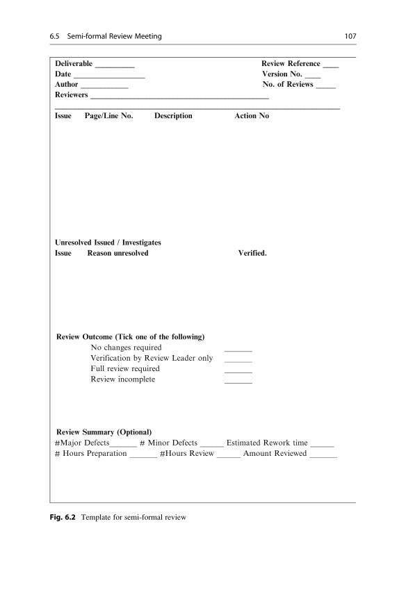
Deliverable __________ Review Reference ____Date __________________ Version No. ____Author ____________ No. of Reviews _____Reviewers _____________________________________________________________________________________________________________________ Issue Page/Line No. Description Action No
Unresolved Issued / InvestigatesIssue Reason unresolved Verified.
Review Outcome (Tick one of the following)No changes required _______Verification by Review Leader only _______Full review required _______Review incomplete _______
Review Summary (Optional)#Major Defects_______ # Minor Defects ______ Estimated Rework time ______# Hours Preparation _______ #Hours Review ______ Amount Reviewed _______
Fig. 6.2 Template for semi-formal review
6.5 Semi-formal Review Meeting 107

6.6 Fagan Inspections
The Fagan methodology (Table 6.4) is a well-known software inspection
methodology. It is a seven-step process and includes planning, overview, prepara-
tion, inspection meeting, process improvement, re-work, and follow-up activity.
Its objectives are to identify and remove errors in the work products, and also to
identify any systemic defects in the processes used to create the work products.
The Fagan inspection process stipulates that requirement documents, design
documents, source code and test plans all be formally inspected by experts inde-
pendent of the author, and the inspection is conducted from different viewpoints
such as requirements, design, test, etc.
There are various roles defined in the inspection process, including the
moderator, who chairs the inspection, the reader, who paraphrases the particular
Table 6.4 Overview Fagan inspection process
Activity
Role/
responsibility Objective
Planning Moderator Identify inspectors and roles.
Verify material is ready for inspection.
Distribute inspection material
Book a room for the inspection.
Overview Author Brief participants on material.
Give background information.
Preparation Inspectors Prepare for the meeting and role to be performed. Checklist may be
employed.
Read through the deliverable and mark up issues/questions.
Inspection
meeting
Moderator/
inspectors
The moderator will cancel the inspection if inadequate preparation
is done.
Time limit set for inspection
Moderator keeps meeting focused.
The inspectors perform their roles
Emphasis on finding defects not solutions.
Defects are recorded and classified.
Author responds to any questions.
The duration of the meeting is recorded.
An inspection outcome is agreed
Process
improvement
Inspectors Continuous improvement of development and inspection process.
The causes of major defects are recorded
A root cause analysis is performed to identify any systemic defect
with the software development process or inspection process.
Recommendations are made to the process improvement team.
Re-work Author The author corrects the defects and carries out any necessary
investigations.
Follow-up Moderator/
author
The moderator verifies that the author has resolved the defects and
investigations.
108 6 Software Inspections

deliverable, the author, who is the creator of the deliverable; and the tester, who is
concerned with the testing viewpoint. The inspection process will consider whether
a design is correct with respect to the requirements, and whether the source code is
correct with respect to the design.
The goal is to identify as many defects as possible, and to confirm the correctness
of a particular deliverable. Inspection data are recorded and may be used to assess
the effectiveness of the organization in detecting and preventing defects.
The moderator records the defects identified during the inspection, and the
defects are classified according to their type and severity. Mature organizations
typically enter defects into an inspection database to allow metrics to be generated,
and to enable analysis to be performed. The severity of the defect is recorded, and
the major defects are classified according to the Fagan defect classification scheme.
Some organizations use other classification schemes, e.g., the orthogonal defectclassification scheme (ODC).
The next section describes the Fagan inspection guidelines, and these include
the recommended time to be spent on the various inspection activities. An organi-
zation may need to tailor the Fagan inspection process to suit its needs, and the
recommended times in the Fagan process may need to be adjusted accordingly.
The tailored guidelines will need empirical evidence to confirm that they are
effective in defect detection.
6.6.1 Fagan Inspection Guidelines
The Fagan inspection guidelines are based on studies by Michael Fagan, and
provide recommendations on the time to spend on the various inspection activities.
The goal is to spend sufficient time to enable the inspection to be effective, and
identify as many major defects as possible. Two tables are presented here: the
strict Fagan guidelines as defined by the Fagan methodology (Table 6.5), and more
relaxed guidelines that have been shown to be effective.
The effort involved in a strict adherence to the Fagan guidelines is substantial,
and the tailored guidelines presented here have been employed in the telecoms
domain. Empirical evidence of the effectiveness of the tailoring is not presented.
Tailoring any methodology requires care, and the effectiveness of the tailoring
should be demonstrated by a pilot prior to its deployment in the organization. This
would generally involve quantitative data on the effectiveness of the inspection
and the number of escaped customer reported defects.
It is important to comply with the guidelines once they are deployed in the
organization, and trained moderators and inspectors will ensure awareness and
compliance. Audits may be employed to verify compliance.
The relaxed guidelines detailed in Table 6.6 do not conform to the strict Fagan
inspection methodology.
6.6 Fagan Inspections 109

6.6.2 Inspectors and Roles
There are four inspector roles identified in a Fagan Inspection and they are
described in Table 6.7.
6.6.3 Inspection Entry Criteria
There are explicit entry and exit criteria defined for the various types of inspections.
These criteria need to be satisfied to ensure that the inspection is effective. The
entry criteria for the various inspections are given in Table 6.8.
6.6.4 Preparation
Preparation is a key part of the inspection process, as the inspection will be
ineffective if the inspectors are insufficiently prepared. The moderator is required
to cancel the inspection if any of the inspectors has been unable to do appropriate
preparation.
Table 6.5 Strict Fagan
inspection guidelinesActivity Area Amount/Hr Max/Hr
Preparation time Requirements 4 pages 6 pages
Design 4 pages 6 pages
Code 100 LOC 125 LOC
Test plans 4 pages 6 pages
Inspection time Requirements 4 pages 6 pages
Design 4 pages 6 pages
Code 100 125 LOC
Test plans 4 pages 6 pages
Table 6.6 Tailored
(Relaxed) Fagan inspection
guidelines
Activity Area Amount/Hr Max/Hr
Preparation Requirements 10–15 pages 30 pages
Time Design 10–15 pages 30 pages
Code 300 LOC 500 LOC
Test plans 10–15 pages 30 pages
Inspection Requirements 10–15 pages 30 pages
Time Design 10–15 pages 30 pages
Code 300 LOC 500 LOC
Test plans 10–15 pages 30 pages
110 6 Software Inspections

Table 6.7 Inspector roles
Role Responsibilities
Moderator Manages the inspection process and ensures compliance to the process.
Plans the inspection and chairs the meeting
Keeps the meeting focused and resolves any conflicts
Keeps to the inspection guidelines
Verifies that the deliverables are ready to be inspected
Verifies that the inspectors have done adequate preparation.
Records the defects on the inspection sheet
Verifies that the agreed follow-up work has been completed.
Skilled in the inspection process and appropriately trained.
Skilful, diplomatic, and occasionally forceful.
Reader Paraphrases the deliverable and gives an independent view of it
Actively participates in the inspection.
Author Creator of the work product being inspected
Has an interest in finding all defects present in the deliverable.
Ensures that the work product is ready to be inspected.
Gives an overview to inspectors (if required)
Participates actively during inspection and answers all questions.
Resolves all identified defects and carries out any required investigation.
Tester Role is focused on how the product would be tested
Role often employed in requirements inspection/test plan inspection
The tester participates actively in the inspection.
Table 6.8 Fagan entry criteria
Inspection type Entry criteria Inspectors/roles
Requirements Inspector(s) with sufficient expertise available Moderator/inspectors
Preparation done by inspectors
Correct requirements template used.
Design inspection Requirements inspected and signed off Moderator/inspectors
Correct design template used to produce design
Inspector(s) have sufficient domain knowledge.
Preparation done by inspectors
Code inspection Requirements/design inspected and signed off Moderator/inspectors
Overview provided
Preparation done by inspectors
Code Listing available
Clean compile of source code
Coding standards satisfied
Inspector(s) have sufficient domain knowledge
Test plan inspection Requirements/design signed off Moderator/inspectors
Preparation done by inspectors
Inspector(s) have sufficient domain knowledge
Correct Test Plan template employed
6.6 Fagan Inspections 111

6.6.5 The Inspection Meeting
The inspection meeting (Table 6.9) consists of a formal meeting between the author
and at least one inspector. It is concerned with finding major defects in the
particular deliverable, and verifying the correctness of the inspected material.
The effectiveness of the inspection is influenced by
– The expertise and experience of the inspector(s)
– Preparation done by inspector(s)
– The speed of the inspection
These factors are quite clear since an inexperienced inspector will lack the
appropriate domain knowledge to understand the material in depth. Second, an
inspector who has inadequately prepared will be unable to make a substantial
contribution during the inspection. Third, the inspection is ineffective if it tries to
cover too much material in a short space of time. The moderator will complete the
inspection form (Fig. 6.3) to record the results from the inspection.
The final part of the inspection is concerned with process improvement.
The inspector(s) and author examine the major defects, identify the root causes
of the defect, and determine corrective action to address any systemic defects in the
software process. The moderator is responsible for completing the inspection
summary form and the defect log form, and for entering the inspection data into
the inspection database. The moderator will give any process improvement sugges-
tions directly to the process improvement team.
Table 6.9 Inspection meeting
Inspection
type Purpose Procedure
Requirements Find requirements defects. Confirm
requirements correct and reflect
customer’s needs.
Inspectors review each page
of requirements and raise questions
or concerns. Defects recorded
by Moderator
Design Find defects in design and confirm its
correctness with respect to requirements
Inspectors review each page of design
(compare to requirements) and raise
questions or concerns. Defects recorded
by Moderator
Code Find defects in the code and confirm its
correctness with respect to the design
and requirements.
Inspectors review the code and compare
to requirements/design, and raise
questions or concerns. Defects recorded
by Moderator.
Test Find defects in test cases/test plan.
Confirm test cases sufficient to verify
the design/requirements.
Inspectors review each page of test
plan/spec., compare to requirements/
design and raise questions or concerns.
Defects recorded by moderator.
112 6 Software Inspections

Inspection Type__________ Deliverable ________________ Project______________Date__________________ Amount Inspected ______ Version No. ____Author_________________ Moderator________________ No. of Reviews _____Inspectors _____________________________________________#Hours Preparation _________ # Hours Inspection __________ #Hours Rework _____Summary of Findings: # Majors _____ # Minors ____ # PIs _____ # INVs ____ ODC Summary (Majors): #CHK __#ASS___#ALG___#TIM___#INT__#FUN____#DOC___#BLD___
______________________________________________________________________ No. Page/Line No. Severity Type Description
Top 3 Root Causes of Major Defects / Process Improvement Actions1.2.3.
Review Outcome No changes Verification by Moderator Full Review Review Incomplete Defects per KLOC _____ Defects per page _____ Verification of Rework _____________Date Verified ________ Inspection Data in Database ____
Fig. 6.3 Template for Fagan inspection
6.6 Fagan Inspections 113

6.6.6 Inspection Exit Criteria
The exit criteria for the various inspections are given in Table 6.10.
6.6.7 Issue Severity
The severity of an issue identified in the Fagan inspection may be classified as
major, minor, a process improvement item, or an item requiring further investiga-
tion. It is classified as major if its non-detection would lead to a defect report being
raised later in the development cycle, whereas a defect report would not be raised
for a minor issue. An issue classified as an investigate item requires further study,
and an issue classified as process improvement is used to improve the software
development process (Table 6.11).
6.6.8 Defect Type
There are several defect-type classification schemes employed in software
inspections. These include the Fagan inspection defect classification (Table 6.12)
and the Orthogonal Defect Classification scheme (Table 6.13).
Table 6.11 Issue severity
Issue severity Definition
Major (M) A defect in the work product that would lead to a customer reported problem
if undetected
Minor (m) A minor issue in the work product
Process (PI) A process improvement suggestion based on analysis of
Improvement (PI) major defects
Investigate (INV) An item to be investigated. It is not clear whether it is a defect or not
Table 6.10 Fagan exit
criteriaInspection type Exit criteria
Requirements Requirements satisfy the customer’s needs
All requirements defects are corrected
Design inspection Design satisfies the requirements.
All identified defects are corrected
Design satisfies the design standards
Code inspection Code satisfies the design and requirements
Code follows coding standards
Code compiles cleanly
All identified defects corrected
Test plan Test plan sufficient to test the requirements
Test plan follows test standards
All identified defects corrected
114 6 Software Inspections

The Orthogonal Defect Classification (ODC) scheme was developed at IBM [4],
and a defect is classified according to three (orthogonal) viewpoints. Thee defecttrigger is the catalyst that led the defect to manifest itself; the defect type indicatesthe change required for correction; and the defect impact indicates the impact of the
defect at the phase in which it was identified. The ODC classification yields a rich
pool of information about the defect, but requires effort to record this information.
The defect type classification is described in Table 6.13.
The defect impact provides a mechanism to relate the impact of the software
defect to customer satisfaction. The defect impact of a defect identified pre-release
to the customer is viewed as the impact of the defect being detected by an end-user,
and for a customer-reported defect, the impact is the actual information reported by
the customer.
The inspection data is typically recorded in the inspection database; this will
enable analysis to be performed on the most common types of defects, and enable
actions to be identified to minimize reoccurrence. The data will enable the phasecontainment effectiveness (PCE) metric to be determined, and to determine if the
software is ready for release to the customer.
Table 6.13 Classification of ODC defect types
Defect type Code Definition
Checking CHK Omission or incorrect validation of parameters or data in conditional
statements
Assignment ASN Value incorrectly assigned or nor assigned at all
Algorithm ALG Efficiency or correctness issue in algorithm
Timing TIM Timing/serialization error between modules, shared resources
Interface INT Interface error (error in communications between modules, operating
system, etc.)
Function FUN Omission of significant functionality
Documentation DOC Error in user guides, installation guides or code comments
Build/Merge BLD Error in build process/library system or version control
Miscellaneous MIS None of the above
Table 6.12 Classification of defects in Fagan inspections
Code inspection Type Design inspections Type Requirements Inspections Type
Logic (code) LO Usability UY Product objectives PO
Design DE Requirements RQ Documentation DS
Requirements RQ Logic LO Hardware interface HI
Maintainable MN Systems interface IS Competition analysis CO
Interface IF
Data usage DA Portability PY Function FU
Performance PE Reliability RY Software interface SI
Standards ST Maintainability MN Performance PE
Code CC Error handling EH Reliability RL
Comments Other ОТ Spelling GS
6.6 Fagan Inspections 115

The ODC classification scheme can give early warning on the quality and
reliability of the software, as experience with the ODC classification scheme
will enable an expected profile of defects to be predicted for the various phases.
The expected profile may then be compared to the actual profile, and clearly it is
reasonable to expect problems if the actual defect profile at the system test phase
resembles the defect profile of the unit testing phase, as the unit testing phase is
expected to identify a certain pool of defect types with system testing receiving
higher-quality software with unit testing defects corrected. Consequently, ODC
may be applied to make predictions of product quality and performance.
The project defects are classified according to some category scheme, for
example, the defects may be categorized by the functional area in which they are
identified, or via the ODC classification scheme as in Fig. 6.4. The frequency of
defects per category is identified, and causal analysis employed to identify actions
to prevent reoccurrence. Often the most problematic areas are targeted first (as in
a pareto chart), and an investigation into the particular category is conducted.
The action plans will identify and carry out improvements to existing processes.
6.7 Automated Software Inspections
Static code analysis is the analysis of software code without executing the code.
It is usually performed with automated tools, and the actual analysis done depends
on the sophistication of the tools. Some tools may analyze individual statements or
Fig. 6.4 Sample-defect types in a project (ODC)
116 6 Software Inspections

declarations, whereas others may analyze the whole source code. The objective
of the analysis is to highlight potential coding errors early in the development
lifecycle.
These tools provide automated software inspections, and provide quality assess-
ment reports on the extent to which the standards are satisfied. Many integrated
development environments (IDEs) provide basic functionality for automated code
reviews. These include Microsoft Visual Studio and Eclipse.
The LDRA Testbed Tool automatically determines the complexity of the
source code, and it provides metrics that give an indication of the maintainability
of the code. A useful feature of the LDRA tool is that it gives a visual picture of
system complexity, and it has a re-factoring tool to assist with reducing complexity.
It automatically generates code assessment reports listing all of the files examined,
and provides metrics on the clarity, maintainability and testability of the code.
Compliance to coding standards is important in producing readable code and in
preventing error-prone coding styles. There are several tools available to check
conformance to coding standards including the LDRA TBvision tool, which has
reporting capabilities to show code quality as well as fault detection and avoidance
measures. It includes functionality to allow users to view the results presented
intuitively in various graphs and reports.
6.8 Review Questions
1. What are software inspections?
2. Explain the difference between informal reviews, structured walkthroughs
and formal inspections?
3. What are the benefits of software inspections?
4. Describe the seven steps in the Fagan Inspection process.
5. What is the purpose of entry and exit criteria?
6. What factors affect the effectiveness of a software inspection?
7. Describe the roles involved in a Fagan inspection.
8. Describe the benefits of automated inspections.
6.9 Summary
The objective of software inspections is to build quality into the software product,
and there is clear evidence that the cost of correction of a defect increases the later
in the development cycle in which it is detected. Consequently, there is an eco-
nomic argument to employing software inspections, as it is more cost effective to
build quality in rather than adding it later in the development cycle.
There are several approaches to software inspections, and these vary in the level
of formality employed. A simple informal approach consists of a walkthrough of
the document or code by an individual other than the author. The meeting is
6.9 Summary 117

informal and usually takes place at the author’s desk or in a meeting room, and the
reviewer and author discuss the document or code informally.
There are formal software inspection methodologies such as the well-known
Fagan inspection methodology. This approach includes pre-inspection activity,
an inspection meeting, and post-inspection activity. Several inspection roles are
typically employed, including an author role, an inspector role, a tester role, and a
moderator role.An organization will need to devise an inspection process which is suitable for
its particular needs. The level of formality is influenced by its business, its culture,
and the potential impact of a software defect on its customers. It may not be
possible to have all of the participants present in a room, and participation by
conference call or video link may be employed. A formal inspection process may
not suit some organization cultures, and an informal approach such as a structured
walkthrough may be the adopted approach.
Software inspections play an important role in building quality into each phase,
and in ensuring that the quality of the delivered product is good. The quality of the
delivered software product is only as good as the quality at the end each phase, and
therefore a phase should be exited only when the desired quality has been achieved.
The effectiveness of an inspection is influenced by the expertise of the inspectors,
adequate preparation, and speed of the inspection, and compliance to the inspection
process. The inspection methodology provides guidelines on the inspection and
preparation rates for an inspection, and guidelines on the entry and exit criteria for
an inspection.
118 6 Software Inspections

Software Testing 7
Key Topics
Test Planning
Test Reporting
Unit Testing
System Testing
Acceptance Testing
Performance Testing
White Box Testing
Black Box Testing
Test Tools
Test Environment
E-commerce Testing
7.1 Introduction
Testing plays a key role in verifying the correctness of software, and confirming
that the requirements are correctly implemented. It is a constructive and destructive
activity in that while on the one hand it aims to verify correctness, on the other hand
it aims to find as many defects as possible. In a mature software company the
majority of defects (e.g., 80 %) will be detected by software inspections, with the
remainder detected by the various forms of testing conducted in the organization.
Software testing provides confidence that the product is ready for release to
potential customers, and the recommendation of the testing department is crucial
in the decision as to whether the software product is ready to be released. The
advice of the test manager highlights any risks associated with the product, and
these are considered prior to its release. The test manager and test department can
G. O’Regan, Introduction to Software Quality, Undergraduate Topicsin Computer Science, DOI 10.1007/978-3-319-06106-1_7,# Springer International Publishing Switzerland 2014
119

be influential in an organization by providing strategic advice on product quality,
and by encouraging organization change to improve the quality of the software
product through the use of best practice in software engineering.
The testers need a detailed understanding of the software requirements to test the
software effectively. Test planning commences at the early stages of the project, and
testers play a role in building quality into the software product as well as verifying its
correctness. The testers typically participate in the review of the requirements, and
thus play an important role in ensuring that the requirements are correct and are
testable. They develop an appropriate testing environment to enable effective testing
to take place, and identify the resources, hardware, and test tools required. The test
plan for the project is documented (this could be part of the project plan), and it
includes the personnel involved, the resources required, the effort required, the
definition of the test environment and the test tools, and the planned schedule. There
is a separate plan for the actual test cases to verify that the requirements have been
implemented correctly, and these test cases include the purpose of the test case, the
inputs and expected outputs, and the test procedure for the particular test case.
The project testing performed includes unit testing, integration, system, regres-
sion, performance, and acceptance testing. The unit testing is performed by the
software developers, and the objective is to verify the correctness of a module. This
type of testing is termed “white box” testing, and is based on knowledge on the
internals of the software module. White box testing involves checking that every
path in a module has been tested, and it involves defining and executing test cases to
ensure code and branch coverage. The objective of “black box” testing is to verify
the functionality of a module or feature or the complete system itself.
Testing is both a constructive activity in that it is verifying the correctness of the
functionality, and it also serves as a destructive activity in that another objective is to
find defects in the software. Test reporting is a key part of the project, as this enables
all project participants to understand the current quality of the software, and know
what needs to be done to ensure that the product is meets the required quality criteria.
The test results are reported regularly throughout the project, and once the tester
discovers a defect, a problem report is opened, and the problem is analysed and
corrected by the software developers. The problem may indicate a genuine defect, a
misunderstanding by the tester, or a request for an enhancement. An independent test
group is more effective than a test group that is directly reporting to the development
manager, as it helps to ensure that quality is not compromised during the inevitable
pressures to make committed delivery dates. A good test group will play a proactive
role in quality improvement, and this may involve participation in the analysis of the
defects identified during testing phase at the end of the project, with the goal of
prevention or minimization of reoccurrence of defects.
The test manager and test team write a test plan for the project, and the plan is
reviewed by independent experts. This ensures that it is of a high quality and that
the test cases are sufficient to confirm the correctness of the requirements. Effective
testing requires sound test planning and execution, and a mature test process in
the organization. Statistics are typically maintained to determine the effectiveness
of the software testing.
120 7 Software Testing

The testing effort is often complicated by real world issues such as late delivery
of the software from the developers. Software development is challenging, and
deadline-driven, and missed deadlines potentially lead to the compression of the
testing cycle, as the project manager may wish to stay with the original schedule.
There are risks associated with shortening the test cycle as it may mean that the
testers are unable to gather sufficient data to make an informed judgment as to
whether the software is ready for release, with the obvious implication that a defect-
laden product may be shipped. Test departments may be understaffed, as manage-
ment may consider additional testers to be expensive and wish to minimize costs.
7.2 Test Process
The quality of the testing is dependent on the maturity of the test process, and a
good test process will include test planning, test case analysis and design, test
execution and test reporting. A simplified test process is sketched in Fig. 7.1 and the
test process will include:
– Test planning and risk management
– Dedicated test environment and test tools
– Test case definition
– Test automation
– Formality in handover to test department
– Test execution
– Test result analysis
– Test reporting
– Measurements of test effectiveness
– Post mortem and test process improvement.
Test planning consists of a documented plan defining the scope of testing to be
performed, the definition of the test environment, the sourcing of any required
hardware or software for the test environment, the estimation of effort and resources
for the various activities, risk management, the deliverables to be produced, the key
milestones, the various types of testing to be performed, the schedule, etc. The test
plan is generally reviewed by the affected parties to ensure its correctness, and that
everyone understands and agrees to their responsibilities. The test planmay be revised
in a controlled manner during the project. It will be described in detail in Sect. 7.3.
The test environment varies according to the type of business and project
requirements. Large organizations may employ dedicated test laboratories, whereas a
single workstation may be sufficient in a small organization. A dedicated test environ-
ment may require significant capital investment, but will pay for itself in reducing the
cost of poor quality by verifying the quality of the software and in identifying defects.
The test environment includes the hardware and software needed to verify the
correctness of the software. It needs to be defined early in the project so that any
required hardware or software may be ordered in time. Tools for simulation of parts
of the system may be required; automated regression and performance test tools
may be required; as well as tools for defect reporting and tracking.
7.2 Test Process 121

The software developers produce a software build under configurationmanagement
control, and the build is verified for integrity to ensure that testing may commence.
There is generally a formal or informal handover of the software to the test department,
and the formal handover generally includes documented criteria that must be satisfied
Fig. 7.1 Simplified test process
122 7 Software Testing

for the handover to take place. The test department must also be ready for testing with
the test cases and test environment prepared.
The various types of testing employed to verify the correctness of the software
are described in Table 7.1.
Good test cases are essential for effective testing, and the test cases need to be
complete in the sense that their successful execution will provide confidence in the
correctness of the software. Hence, the test cases must relate or cover the software
requirements, and earlier in Chap. 4 (Table 4.4) we discussed the concept of a
traceability matrix that maps the requirements to the design and test cases, and
therefore provides confidence that each requirement has a corresponding test case
for verification. The test cases will consist of a format similar to the following:
– Purpose of test case
– Setup required to execute the test case
– Inputs to the test case
– The test procedure
– Expected outputs or results
The test execution will follow the procedure outlined in the test cases, and the
tester will compare the actual results obtained with the expected results. The test
Table 7.1 Types of testing
Test type Description
Unit testing This testing is performed by the software developers, and it verifies the
correctness of the software modules.
Component
testing
This testing is used to verify the correctness of software components, to ensure
that the component is correct and may be reused.
System testing This type of testing is usually carried out by an independent test group to verify
the correctness of the complete system.
Performance
testing
This testing is typically carried out by an independent test group to ensure that
the performance of the system is within the defined limits. It may require tools
to simulate clients and heavy loads, and precise measurements of performance
are made.
Load/stress
testing
This testing is employed to verify that the system performance is within the
defined limits for heavy system loads over long or short periods of time.
Browser
compatibility
This testing is specific to web based applications and verifies that the web site
functions correctly with the supported browsers.
Usability testing This testing verifies that the software is easy to use, and that the look and feel
of the application is good.
Security testing This testing verifies that the confidentiality, integrity and availability
requirements are satisfied
Regression
testing
This testing verifies that the core functionality is preserved following changes
or corrections to the software. Test tools may be employed to increase its
productivity and efficiency.
Test simulation This testing simulates part of the system where the real system currently does
not exist, or where the real live situation is hard to replicate.
Acceptance
testing
This testing carried out by the customer to verify that the software matches the
customer’s expectations prior to acceptance.
7.2 Test Process 123
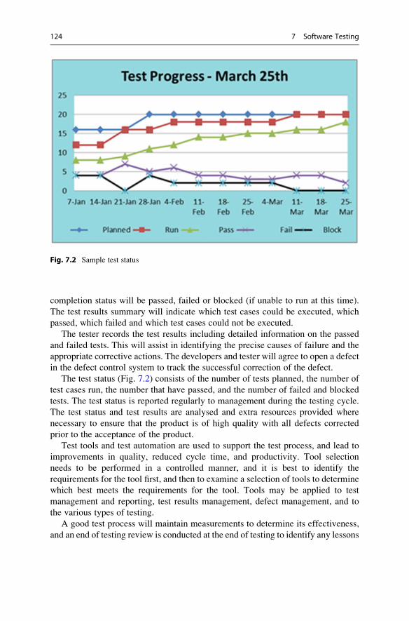
completion status will be passed, failed or blocked (if unable to run at this time).
The test results summary will indicate which test cases could be executed, which
passed, which failed and which test cases could not be executed.
The tester records the test results including detailed information on the passed
and failed tests. This will assist in identifying the precise causes of failure and the
appropriate corrective actions. The developers and tester will agree to open a defect
in the defect control system to track the successful correction of the defect.
The test status (Fig. 7.2) consists of the number of tests planned, the number of
test cases run, the number that have passed, and the number of failed and blocked
tests. The test status is reported regularly to management during the testing cycle.
The test status and test results are analysed and extra resources provided where
necessary to ensure that the product is of high quality with all defects corrected
prior to the acceptance of the product.
Test tools and test automation are used to support the test process, and lead to
improvements in quality, reduced cycle time, and productivity. Tool selection
needs to be performed in a controlled manner, and it is best to identify the
requirements for the tool first, and then to examine a selection of tools to determine
which best meets the requirements for the tool. Tools may be applied to test
management and reporting, test results management, defect management, and to
the various types of testing.
A good test process will maintain measurements to determine its effectiveness,
and an end of testing review is conducted at the end of testing to identify any lessons
Fig. 7.2 Sample test status
124 7 Software Testing
that need to be learned for continual improvement. The test metrics employed will
answer questions such as:
• What is the current quality of the software?
• How stable is the product at this time?
• Is the product ready to be released at this time?
• How good was the quality of the software that was handed over?
• How does the product quality compare to other products?
• How effective was the testing performed on the software?
• How many open problems are there?
• How much testing remains to be done?
7.3 Test Planning
Testing requires good planning and execution to be effective. Testing is a sub-project
of a project and needs to be managed as such, and the IEEE 829 standard includes a
template for test planning. Test planning involves defining the scope of the testing to
be performed; defining the test environment; estimating the effort required to define
the test cases and to perform the testing; identifying the resources needed (including
people, hardware, software, and tools); assigning the resources to the tasks; defining
the schedule; identifying any risks to the schedule or quality and managing them;
tracking progress and taking corrective action; re-planning as appropriate where the
scope of the project has changed; providing test reports to give visibility of the test
status to the full project team, including the number of test planned, executed, passed,
blocked and failed; re-testing corrections to failed or blocked test cases; taking
corrective action to ensure quality and schedule are achieved; and providing a final
test report with a recommendation to go to acceptance testing. Test management
involves:
• Identify the scope of testing to be done
• Determine types of testing to be performed
• Estimates of time, resources, people, hardware, software and tools
• Determine how test progress and results will be communicated
• Define how test defects will be logged and reported
• Provide resources needed
• Provision of test environment
• Assignment of people to tasks
• Define the schedule
• Identify and manage risks
• Track progress and take corrective action
• Provide regular test status of passed, blocked, failed tests
• Re-plan if scope of the project changes
• Conduct post mortem to learn any lessons
The scope of the testing is dependent on the requirements of the proposed
system. The estimate for the various activities is determined and is used in the
schedule. Table 7.2 shows a simple test schedule for a small project, and the test
7.3 Test Planning 125

manager will often employ Microsoft Project for planning and tracking for larger
projects (e.g., Fig. 3.2). The activities in the test plan are tracked and updated to
record the tasks that have been completed, and dates are re-scheduled as appropri-
ate. Testing is a key sub-project of the main project, and the project manager will
track the key test milestones and will maintain close contact with the test manager.
It is essential to track the schedule, and to record the actual and estimated
completion dates, and to reschedule accordingly. It is prudent to consider risk
management early in test planning, and to identify risks that could potentially
materialize during the testing project, estimate the probability and impact if a risk
does materialize, and identify (as far as is practical) actions to mitigate the risk or a
contingency plan to address the risk if it materialises.
7.4 Test Case Design and Definition
Several types of testing that may be performed were described in Table 7.2, and
there is often a separate test plan for Unit, System and UAT testing. The unit tests
are based on the software design; the system tests are based on the system
requirements (or functional requirements specification); and the UAT tests are
based on the business (or user) requirements.
Each of these test plans contains test scripts (e.g., the Unit Test Plan contains the
Unit Test scripts and so on), and the test scripts are traceable to the design (for the
Unit Tests), and for the system requirements (for the System Test scripts). The unit
tests are more focused on white box testing whereas the system test and UAT tests
are focused on black box testing.
Each test script contains the objective of the test script and the procedure by
which the test is carried out. Each test script includes:
– Test Case ID
– Test Type (e.g., Unit, System, UAT)
– Objective/Description
– Test Script Steps
– Expected Results
Table 7.2 Sample test schedule
Activity Resource name(s) Start date End/Re-plan date Comments
Review requirements Test team 15.02.2013 16.02.2013 Complete
Project test plan & review Test manager 15.02.2013 28.02.2013 Complete
System test plan/review Tester 1 01.03.2013 22.03.2013 Complete
Performance test plan/review Tester 2 15.03.2013 31.03.2013 Complete
Regression plan/review Tester 1 01.03.2013 15.03.2013 Complete
Set up test environment Tester 1 15.03.2013 31.03.2013 Complete
System testing Tester 1 01.04.2013 31.05.2013 In progress
Performance testing Tester 2 15.04.2013 07.05.2013 In progress
Regression testing Tester 2 07.05.2013 31.05.2013 In progress
Test reporting Test manager 01.04.2013 31.05.2013 In progress
126 7 Software Testing

– Actual Results
– Tested By
Regression testing involves carrying out a subset of the defined tests, and are
carried out to verify that the core functionality remains in place following changes
to the system.
7.5 Test Reporting and Project Sign-off
Testing is a sub-project of the project, and the test manager will report progress
regularly during the project. The report provides the current status of testing for the
project and includes:
• Quality Status (including tests run, passed and blocked).
• Risks and issues
• Status of Test Schedule
• Deliverables planned (next period)
The test manager discusses the test status with management, and highlights the
key risks and issues to be dealt with. The test manager may require management
support to deal with these.
The test status is important in judging whether the software is ready to be
released to the customer. Various quality metrics may be employed to measure
the quality of the software, and the key risks and issues are considered. The test
manager will make a recommendation to release or not based on the actual test
status. One useful metrics is the cumulative arrival rate (Fig. 7.3) which gives an
indication of the stability of the product.
The slope of the curve is initially steep as defects are detected; as testing proceeds
and defects are corrected and retested, the slope of the curves levels off, and indicates
that the software has stabilized and is potentially ready to be released to the customer.
Fig. 7.3 Cumulative defects
7.5 Test Reporting and Project Sign-off 127

However, it is important not to rush to conclusions based on an individual
measurement. For example, the chart in Fig. 7.3 could possibly indicate that testing
halted on May 13th with no testing since then, and that would explain why the
defect arrival rate per week is zero. Careful investigation and analysis needs to be
done before the interpretation of a measurement is made, and usually several
measurements rather than one are employed in sound decision making.
7.6 Testing and Quality Improvement
Testing is an essential part of the software development process, and the
recommendation of the test manager is considered in the decision to release the
software product. Decision making is based on objective facts, and measurements
are employed to assess the quality of the software. The cumulative test arrival rate
(Fig. 7.3) gives an indication of the stability of the software product, and may be
used in conjunction with other measures to decide on whether it is appropriate to
release the software, or whether further testing should be performed.
Test defects are valuable in the sense that they enable an organization an
opportunity to improve its software development process, to prevent them from
reoccurring in the future. A mature development organization will perform internal
reviews of requirements, design, and code prior to testing. The effectiveness of the
internal review process and the test process may be seen in the phase containment
metric (PCE).
Figure 7.4 indicates that the project had a phase containment effectiveness of
approximately 54 %. That is, the developers identified 54 % of the defects, the
system testing phase identified approximately 23 % of the defects, acceptance
testing identified approximately 14 % of the defects, and the customer identified
approximately 9 % of the defects. Many organizations set goals with respect to the
Fig. 7.4 Phase containment effectiveness metric
128 7 Software Testing

phase containment effectiveness of their software. For example, a mature organi-
zation might aim for their software development department to have a phase defect
effectiveness goal of 80 %. This means that 80 % of the defects should be found by
software inspections.
The PCE chart measures the current phase containment effectiveness, and
improvement trends of the PCE may be tracked over time. There is no point in
setting a goal for a particular group or area unless there is a clear mechanism to
achieve the goal. Thus to achieve a goal of 80 % phase containment effectiveness
the organization will need to implement a formal software inspection methodology
as described in the previous chapter. Training on inspections will be required and
the effectiveness of software inspections monitored and improved.
A mature organization will aim to have 0 % of defects reported by the customer,
and this goal requires improvements in its software inspection methodology and its
software testing methodology. Measurements provide a way to verify that the
improvements have been successful. Each defect is potentially valuable as it, in effect,
enables the organization to identify weaknesses in the software process and to target
improvements.
Escaped customer defects offer an opportunity to improve the testing process, as
an escaped customer defect indicates a weakness in the test process. These are
categorized, causal analysis is performed, and corrective actions to improve the
testing process are identified. This helps to prevent a reoccurrence of the defects.
Thus software testing plays an important role is quality improvement.
7.7 Traceability of Requirements
The objective of requirement traceability is to verify and validate that all of the
requirements for the project have been implemented and tested. One way to do this
would be to examine each requirement number and to go through every part of the
design document to find any reference to the particular requirement number, and
similarly to go through the test plan and find any reference to the requirement
number. This would demonstrate that the particular requirement number has been
implemented and tested.
A more effective mechanism to do this was discussed in Chap. 4, and this
involves using a trace matrix (Table 4.4) which may be a separate document or
part of the design or test documents. The idea is that a mapping between the
requirement numbers and sections of the design or test plan is defined, and this
provides confidence that all of the requirements have been implemented and tested.
Requirements may be numbered or may be detailed in individual sections of the
requirements document. A requirement number may map on to several sections of
the design or to several test cases, i.e., the mapping may be one to many. Traceabil-
ity provides confidence that each requirement number has been implemented in the
software design and tested via the test plan.
7.7 Traceability of Requirements 129

• The trace matrix provides the mapping between each requirement number
(or sections), and the associated test cases to verify that it has been correctly
implemented.
• This mapping will typically be one to many (i.e., for a particular requirement,
several test cases may be employed to demonstrate correctness).
7.8 Test Tools
Test tools are employed to support the test process, and are used to enhance quality,
reduce cycle time, and increase productivity. Tool selection needs to be planned, and
the evaluation plan includes the activities involved in the evaluation, the estimated
and actual effort to complete, and the individual carrying out the activity. The
evaluation and selection of a particular tool involves identifying the requirements
for the proposed tool, and identifying tools to evaluate against the requirements. Each
tool is then evaluated to yield a tool evaluation profile, and the results are analysed to
enable an informed decision to be made. This is described in more detail in Chap. 16.
There are various tools to support testing such as test planning and management
tools; defect tracking tools; regression test automation tools; performance tools; and
so on. There are tools available from various vendors such as Compuware, Software
Research, Inc., McCabe and Associates, and IBM Rational.
7.8.1 Test Management Tools
There are various test management tools available (e.g., the Quality Center tool
from HP), and the main features of such a tool are:
• Management of entire testing process
• Test planning
• Support for building and recording test scripts
• Test status and reporting
• Graphs for presentation
• Defect control system
• Support for many testers
• Support for large volume of test data
• Audit trail proof that testing has been done
• Test automation
• Support for various types of testing
The Quality Center™ tool standardizes and manages the entire test and quality
process, and is a web-based system for automated software quality management
and testing. It employs dashboard technology to give visibility into the process.
It provides a consistent repeatable process for gathering requirements; planning
and scheduling tests; analyzing results; and managing defects. It supports a high-
level of collaboration and communication between the stakeholders. It allows
the business analysts to define the application requirements and testing objectives.
130 7 Software Testing

The test managers and testers may then design test plans, test cases and automated
scripts. The testers then run the manual and automated tests, report results and log
the defects. The developers review and correct the logged defects. Project and test
managers can create status reports and manage test resources. Test and product
managers decide objectively whether the application is ready to be released.
7.8.2 Miscellaneous Testing Tools
There is a wide collection of test tools to support activities such as static testing,
unit testing, system testing, performance testing, and regression testing.
Code coverage tools are useful for unit testing, and, for example, the LDRA
Testbed is able to analyse source files to report on areas of code that were not
executed at run time, thereby facilitating the identification of missing test data.
Code coverage tools are useful in identifying the sources of errors as they will
typically show the code areas that were executed through textual or graphic reports.
Regression testing involves re-running existing test cases to verify that the
software remains correct following the changes made. It is often automated with
capture and playback tools, and the Winrunner tool which was developed by
Mercury (now part of HP) captures, verifies and replays user interactions, and
allows regression testing to be automated. The Winrunner tool has been replaced
by HP Unified Functional Testing Software. Effort is required to set up the tests for
automation, but the payback is improvements in quality and productivity.
The purpose of performance testing is to verify that system performance is
within the defined limits, and it requires measures on the server side, network
side, and client side (e.g., processor speed, disk space used, memory used, etc.).
It includes load testing and stress testing. . Mercury’s LoadRunner tool allows the
software application to be tested with hundreds or thousands of concurrent users to
determine its performance under heavy loads. It allows the scaleability of the
software system to be tested to determine if can support the predicted growth.
The decision on whether to automate and what to automate often involves a test
process improvement team. It tends to be difficult for a small organization to make a
major investment in test tools (especially if the projects are small). However, larger
organizations will require a more sophisticated testing process to ensure that high-
quality software is consistently produced.
7.9 E-commerce Testing
There has been an explosive growth in electronic commerce, and web site quality
and performance is a key concern. A web site is a software application and so
standard software engineering principles are employed to verify the quality of a
web site. E-commerce applications are characterized by:
• Distributed system with millions of servers and billions of participants
• Often rapid application development is required
• Design a little, implement a little, and test a little
7.9 E-commerce Testing 131
• Rapidly changing technologies
• Users may be unknown
• Browsers may be unknown
• High availability requirements (24 *7 * 365)
• Look and feel of the web site is highly important
• Performance may be un-predictable
• Security threats may be from anywhere
The standardwaterfall lifecyclemodel is rarely employed for the front end of aweb
application, and instead RAD/JAD/Agile models are usually employed. The use of
lightweight development methodologies does not mean that anything goes in software
development, and similar project documentation is produced (except that the chrono-
logical sequence of delivery of the documentation is more flexible). Joint application
development allows early user feedback to be received on the look and feel and
correctness of the application, and the method of design a little, implement a little,
and test a little is valid for web development. The various types of web testing include:
• Static testing
• Unit testing
• Functional Testing
• Browser compatibility testing
• Usability testing
• Security testing
• Load/performance/stress testing
• Availability testing
• Post deployment testing
Static testing generally involves inspections and reviews of documentation. The
purpose of static testing of web sites is to check the content of the web pages for
accuracy, consistency, correctness, and usability, and also to identify any syntax
errors or anomalies in the HTML. There are tools available (e.g., NetMechanic) for
statically checking the HTML for syntax correctness.
The purpose of unit testing is to verify that the content of the web pages
correspond to the design, that the content is correct, that all the links are valid,
and that the web navigation operates correctly.
The purpose of functional testing is to verify that the functional requirements are
satisfied. It may be quite complex as ecommerce applications may involve product
catalogue searches, order processing, credit checking and payment processing, and
the application may liaise with legacy systems. Also, testing of cookies, whether
enabled or disabled, needs to be considered.
The purpose of browser compatibility testing is to verify that the web browsers
that are to be supported are actually supported. The purpose of usability testing is to
verify that the look and feel of the application is good, and that web performance
(loading web pages, graphics, etc.) is good. There are automated browsing tools
which go through all of the links on a page, attempt to load each link, and produce a
report including the timing for loading an object or page. Usability needs to be
considered early in design, and is important in GUI applications.
132 7 Software Testing

The purpose of security testing is to ensure that the web site is secure. The
purpose of load, performance and stress testing is to ensure that the performance of
the system is within the defined parameters.
The purpose of post-deployment testing is to ensure that web site performance
remains good, and thismay be done as part of a service level agreement (SLA). A SLA
typically includes a penalty clause if the availability of the system or its performance
falls below defined parameters. Consequently, it is important to identify performance
and availability issues early before they become a problem. Thus post-deployment
testing includes monitoring of web site availability, performance, and security, and
taking corrective action. Ecommerce sites operate 24 h a day for 365 days a year, and
major financial loss is incurred in the case of a major outage.
7.10 Review Questions
1. Describe the main activities in test planning.
2. What does the test environment consist of? When should it be set up?
3. What are the benefits of traceability of the requirements to the test cases?
4. Describe the various types of testing that may be performed.
5. Investigate available test tools to support testing? What areas of testing do
they support and what are their benefits?
6. Describe an effective way to evaluate and select a test tool.
7. What are the characteristics of e-commerce testing that make it unique
from other domains.
7.11 Summary
This chapter considered software testing in detail and discussed how testing may be
used to verify that the software is of a high quality and fit to be released to potential
customers. Testing is both a constructive and destructive activity, in that while on
the one hand it aims to verify correctness, on the other hand it aims to find as many
defects as possible.
Various test activities were discussed including test planning, the test environ-
ment setup, test case definition, test execution, defect reporting, and test manage-
ment and reporting.
Various types of testing were discussed including black and white box testing,
unit and integration testing, system testing, performance testing, security and
usability testing. Testing in an e-commerce environment was considered. The
unit testing is performed by the software developers, and the objective is to verify
the correctness of a module.
7.11 Summary 133

Test reporting enables all project participants to understand the current quality of
the software, and are aware of what needs to be done to ensure that the product is
meets the required quality criteria.
Various tools to support the testing process were discussed, and a methodology
to assist in the selection and evaluation of tools was considered.
Metrics to provide visibility into progress with the testing and the quality of the
software were discussed, and also the role of testing in promoting quality improve-
ment was discussed.
The testing effort is often complicated by real world issues such as late delivery
of the software from the developers. This may lead to the compression of the testing
cycle, as the project manager may wish to stay with the original schedule.
134 7 Software Testing

Supplier Selection and Management 8
Key Topics
Request for Proposal
Supplier Evaluation
Formal Agreement
Statement of Work
Service Level Agreement
Escrow
8.1 Introduction
Supplier selection and management is concerned with the selection and management
of a third-party software supplier. Many large projects involve total or partial out-
sourcing of the software development, and it is therefore essential to select a supplier
who is capable of delivering high-quality and reliable software on time and on budget.
This means that the process for the selection of the supplier needs to be rigorous,
and that the capability of the supplier is clearly understood, as well as identifying
any risks associated with the supplier. The selection is based on objective criteria
such as the ability to deliver the required solution, and while cost is an important
criterion it is just one among several other important factors.
Once the selection is finalised a legal agreement is drawn up which usually
includes the terms and condition of the contract as well as a statement of work
(which details the work to be carried out, the deliverables to be produced, when they
will be produced, the personnel involved and their roles and responsibilities, and the
standards to be followed). The supplier then commences the defined work, and is
appropriately managed for the duration of the contract. The activities listed in
Table 8.1 are generally employed in supplier selection and management.
G. O’Regan, Introduction to Software Quality, Undergraduate Topicsin Computer Science, DOI 10.1007/978-3-319-06106-1_8,# Springer International Publishing Switzerland 2014
135

8.2 Planning and Requirements
The potential acquisition of software arises as part of a make-or-buy analysis at
project initiation. The decision is whether the project team should (or has the
competence to) develop a particular software system (or component of it), or whether
there is a need to outsource (or purchase off-the-shelf) the required software.
The supplied software may be the complete solution to the project’s requirements,
or it may need to be integrated with other software produced for the project. The
following tasks are involved:
– The requirements are defined (these may be a subset of the overall business
requirements)
– The solution may be an available in an off-the-shelf software package (with
configuration needed to meet the requirements)
Table 8.1 Supplier selection and management
Activity Description
Planning and
requirements
This involves defining the approach to the procurement. It involves:
Defining the procurement requirements
Forming the evaluation team to rate each supplier against objective
criteria.
Identify suppliers This involves identifying suppliers and may involve research,
recommendations from colleagues or previous working relations. Usually
three to five potential suppliers will be identified.
Prepare and issue RFP This involves the preparation and issuing of the Request for Proposal
(RFP) to potential suppliers. The RFP may include the evaluation criteria
and preliminary legal agreement.
Evaluate proposals The received proposals are evaluated and a short-list of the suppliers
invited to present.
Select supplier Each supplier makes a presentation followed by a Q&A session.
The evaluation criteria are completed for each supplier and reference sites
checked (as appropriate). The decision on the preferred supplier is made.
Define supplier
agreement
A formal agreement is made with the supplier. This may include
Negotiations with the supplier/involvement with Legal Department.
Agreement may vary (Statement of Work, Service Level Agreement,
Escrow, etc.)
Formal Agreement signed by both parties
Unsuccessful parties informed
Purchase Order raised
Project monitoring
and control
This is concerned with monitoring and control of the supplier. It includes
monitoring progress project risks, milestones and issues and change
control management
Acceptance This is concerned with the acceptance of the software and involves
acceptance testing to ensure that the supplied software is fit for use.
Rollout This is concerned with the deployment of the software and support/
maintenance activities.
136 8 Supplier Selection and Management

– The solution may be to outsource all or part of the software development
– The solution may be a combination of the above.
Once the decision has been made to outsource or purchase an off-the-shelf
solution an evaluation team is formed to identify potential suppliers, and evaluation
criteria is defined to enable each supplier’s solution to be objectively rated. A plan
will be prepared by the project manager detailing the approach to procurement,
defining how the evaluation will be conducted, defining the members of the
evaluation team and their roles and responsibilities, and preparing a schedule of
the procurement activities to be carried out.
8.3 Identifying Suppliers
A list of potential suppliers may be determined in various ways including:
– Previous working relationship with suppliers
– Research via the Internet/Gartner
– Recommendations from colleagues or another company
– Advertisements/other
A previous working relationship with a supplier provides useful information
on the capability of the supplier, and whether it would be a suitable candidate for
the work to be done. Companies will often maintain a list of preferred suppliers, and
these are the suppliers that have worked previously with the company, and whose
capability is known. The risks with a supplier on the preferred supplier list are
generally less than those of an unknown supplier. If the experience of working with
the supplier is poor, then the supplier may be removed from the preferred supplier list.
For public procurement there may be additional requirements to ensure fairness
in the procurement process, and often these public contracts need to be more widely
advertised to allow all interested parties the opportunity to make a proposal to
provide the product or service.
The list of candidate suppliers may potentially be quite large, and so shortlisting
may be employed to reduce the list to a more manageable size of around five
candidate suppliers.
8.4 Prepare and Issue RFP
The Request for Proposal (RFP) is prepared and issued to the short-listed suppliers,
and the suppliers are required to complete a proposal detailing the solution that they
will provide, as well as the associated costs, by the closing date. The proposal will
need to detail the specifics of the supplier’s solution, and it needs to show how the
supplier plans to implement the requirements.
The RFP details the requirements for the software, and must contain sufficient
detail to allow the candidate supplier to provide a complete and accurate response.
The completed proposal will include technical and financial information, and this
will allow a rigorous evaluation of each received proposal to be carried out.
8.4 Prepare and Issue RFP 137

The RFP may include the criteria defined to evaluate the supplier, and often
weightings are employed to reflect the importance of individual criteria. The
evaluation criteria may include several categories such as:
– Functional (related to business requirements)
– Technology (related to the technologies/non-functional requirements).
– Supplier capability and maturity
– Delivery approach
– Overall Cost
Once the proposals have been received further shortlisting may take place to
limit the formal evaluation to around three suppliers.
8.5 Evaluate Proposals and Select Supplier
The evaluation team will evaluate all received proposals using an evaluation spread
sheet, and the results are employed to produce a short list of around three suppliers.
The short-listed suppliers are then invited to make a presentation to the evalua-
tion team, and this allows the team to question each supplier in detail to gain a better
understanding of the solution that they are offering, and any risks associated with
the supplier and their proposed solution.
Following the presentations and Q&A sessions the evaluation team will follow
up with checks on reference sites for each supplier. The evaluation spread sheet is
updated with all the information gained from the presentations, the reference site
checks, and the risks associated with individual suppliers.
Finally, an evaluation report is prepared to give a summary of the evaluation,
and this includes the recommendation of the preferred supplier. The project board
then makes a decision to accept the recommendation, select an alternate supplier, or
restart the procurement process.
8.6 Formal Agreement
The preferred supplier is informed on the outcome of the evaluation and negotia-
tions on a formal legal agreement commences. The agreement will need to be
signed by both parties, and may (depending on the type of agreement) include:
– Legal Contract
– Statement of Work
– Implementation Plan
– Training Plan
– User Guides and Manuals
– Customer Support to be provided
– Service Level Agreement
– Escrow Agreement
– Warranty Period
138 8 Supplier Selection and Management
The statement of work (SOW) is employed in bespoke software development,
and it details the work to be carried out, the activities involved, the deliverables to
be produced, the personnel involved and their roles and responsibilities.
A service level agreement (SLA) is an agreement between the customer and
service provider which specifies the service that the customer will receive as well as
the response time to customer issues and problems. It will also detail the penalties
should the service performance fall below the defined levels.
An Escrow agreement is an agreement made between two parties where an
independent trusted third party acts as an intermediary between both parties, and
receives money from one and sends it to the other party when contractual obliga-
tions are satisfied. Under an Escrow agreement documents and source code may
also be held by the trusted third party.
8.7 Managing the Supplier
The activities involved in the management of the supplier are similar to the
discussion on project management in Chap. 3. The supplier may be based in a
different physical location (possibly in another country), and so regular communi-
cation is essential for the duration of the contract. The project manager is respon-
sible for managing the supplier, and will typically communicate with the supplier
on a daily basis. The supplier will send regular status reports detailing progress
made as well as any risks and issues. The activities involved include:
– Managing schedule, effort and budget.
– Monitoring progress, project issues and risks
– Managing risks and issues
– Managing changes to the scope of the project
– Obtaining weekly progress reports from the supplier.
– Managing project milestones
– Managing quality
– Reviewing the supplier’s work
– Performing audits of the project
– Monitoring test results and correction of defects.
– Acceptance testing of the delivered software
The project manager needs to manage the risks associated with the supplier
(e.g., supplier delivering late, supplier delivering poor quality, and so on).
8.8 Acceptance of Software
This activity is concerned with acceptance testing to ensure that the software
developed by the supplier is fit for purpose. The supplier software may only be a
part of the system and may need to be integrated with other software. The accep-
tance testing involves:
– Preparation of acceptance test cases (this is the acceptance criteria)
– Planning and scheduling acceptance testing
8.8 Acceptance of Software 139

– Setting up the Test Environment
– Execution of test cases (UAT testing) to verify acceptance criteria is satisfied.
– Test Reporting
– Communication of Defects to Supplier
– Correction of the defects by Supplier
– Re-testing and Acceptance of Software
The project manager will communicate any defects with the software to the
supplier, and the supplier makes the required corrections and modifications to the
software. Re-testing then takes place and once all acceptance tests have success-
fully passed the software is accepted.
8.9 Rollout
This activity is concerned with the rollout of the software at the customer site, and
the handover to the support and maintenance team. It involves:
– Deployment of the software at customer site.
– Provision of training to staff.
– Handover to the Support and Maintenance Team
8.10 Review Questions
1. What are the main activities in supplier selection and management?
2. What factors would lead an organization to seek a supplier rather than
developing a software solution in-house?
3. What are the benefits of out-sourcing?
4. Describe how a supplier should be managed.
5. What is a service level agreement?
6. Describe the purpose of a statement of work?
7. What is an Escrow agreement?
8.11 Summary
Supplier selection and management is concerned with the selection and manage-
ment of a third-party software supplier. Many large projects often involve total or
partial outsourcing of the software development, and therefore it is essential to
select a supplier who is capable of delivering high-quality and reliable software on
time and on budget.
This means that the process for the selection of the supplier needs to be rigorous,
and that the capability of the supplier is clearly understood, as well as any risks.
140 8 Supplier Selection and Management

The selection is based on objective criteria, and cost is one important criterion but it
is one among several other important factors.
Once the selection is finalised a legal agreement is drawn up (which usually
includes the terms and condition of the contract as well as a statement of work
which details the deliverables to be produced, when they will be produced, and the
standards to be followed). The supplier then commences the defined work and is
appropriately managed.
The project manager is responsible for managing the supplier and this involves
communicating with the supplier on a daily basis and managing issues and risks.
The software is subject to acceptance testing before it is accepted from the supplier.
8.11 Summary 141

Software Quality Assurance 9
Key Topics
Auditor
Audit Planning
Audit Meeting
Audit Reporting
Audit Actions
Tracking Actions
Audit Escalation
SQA Team
Independence of Auditor
Training
9.1 Introduction
The purpose of software quality assurance is to provide visibility to management on
the processes being followed and the work products being produced in the organi-
zation. It is a systematic enquiry into the way that things are done in the organi-
zation, and involves conducting audits of projects, suppliers and departments.
It provides:
• Visibility into the processes and standards in use in the organization.
• Visibility into the extent of compliance to the defined processes and standards.
• Visibility into the fitness for use of the work products produced
• Visibility into the effectiveness of the defined processes.
Software quality assurance involves planning and conducting audits; reporting
the results to the affected groups; tracking the assigned audit actions to completion;
and conducting follow up audits, as appropriate. It is generally conducted by the
G. O’Regan, Introduction to Software Quality, Undergraduate Topicsin Computer Science, DOI 10.1007/978-3-319-06106-1_9,# Springer International Publishing Switzerland 2014
143

SQA group,1 and this group is independent of the groups being audited. The
activities involved are given in Table 9.1.
All involved in the audit process need to receive appropriate training. This
includes the participants in the audit who receive appropriate orientation; the auditor
needs to be trained in interview techniques including asking open and closed
questions; effective documentation skills to record the results; and to deal with any
conflicts that might arise during an audit.2
The flow of activities in a typical audit process is sketched in Fig. 9.1, and they
are described in more detail in the following sections.
Table 9.1 Auditing activities
Activity Description
Audit planning Select projects/areas to be audited during period.
Agree audit dates with affected groups
Agree scope of Audit & advise what needs to be brought to the meeting.
Book room & send invitation to the attendees.
Prepare/update the Audit Schedule.
Audit meeting Ask attendees as to their specific role in the project, the activities performed
& determine the extent to which the process is followed.
Employ an Audit Checklist as an aid
Review agreed documentation.
Determine if processes are appropriately followed
Audit reporting Revise notes from the Audit Meeting and review any required additional
documents.
Prepare draft audit report, detail audit actions, and obtain feedback to ensure
accuracy.
Agree closure dates of the audit actions.
Circulate approved report to attendees/management.
Track actions Track audit actions to closure.
Record the audit action status
Escalation (as appropriate) to resolve open actions
Audit closure Once all actions are resolved the audit is closed.
1 This group may vary from a team of auditors in a large organization to a part-time role in a small
organization.2 The auditor may face a situation where one or more individuals become defensive, and will need
to reassure individuals that the objective of the audit is not to find fault with individuals, rather the
objective is to fix a defective process. The culture of an organization has an influence on how open
individuals will be during an audit (for example if there is a blame culture in the organization
rather than an emphasis on fixing the process).
144 9 Software Quality Assurance

Audit schedule
Plan Audit1. Select areas to audit
2. Advise attendees3. Arrange logistics
4. Update audit schedule
1. Updated audit schedule2. Attendees invited3. Logistics dealt with
Conduct audit1. Interview attendees /
roles2. Review documentation3. Determine extent to
which process is followed4. Identify issues to be
addressed
Draft audit report / issues
Audit Reporting 1. Circulate audit report
2. Update Audit Schedule
Updated Audit Actions
Y
Approve auditreport ?
No
Track Actions1. Monitor closure of
actions 2. Update Audit Actions
Approved audit report / issues
Audit Actionscomplete?
YN
Escalate 1. Escalate to management 2. Details of Noncompliance
Escalate action(s)
Close Audit
Y
N
Fig. 9.1 Sample audit
process
9.1 Introduction 145

9.2 Audit Planning
Organizations vary in size and complexity and so the planning required for audits
will vary. In a large organization the quality manager or auditor is responsible for
planning and scheduling the audits. In a small organization the quality assurance
activities may be performed by a part time auditor who has to plan and schedule
the audits.
A representative sample of projects/areas in the organization will be audited,
and the number and types of audits employed will depend on the current maturity of
the organization. Mature organizations with a strong process culture will require
fewer audits, whereas immature organizations may need a larger number of audits
to ensure that the process is ingrained in the way that work is done.
It is essential that the auditor is independent of the area being audited. That is,the auditor should not be reporting to the manager whose area is being audited,
as otherwise important findings in the audit may be omitted from the report.
The independence of the auditor helps to ensure that the findings are fair and
objective, as the auditor may state the facts as they are without fear of negative
consequences.
The auditor needs to be familiar with the process, and in a position to judge the
extent to which the standards have been followed. The audit needs to be factual, as
incorrect statements will lead to a loss of credibility. The planning and scheduling
activities will determine:
– Project/Area to be audited
– Planned Date of Audit
– Scope of Audit
– Checklist to be used
– Documentation required
– Auditor
– Attendees
The auditor may receive orientation on the project/area to be audited prior to
the meeting, and may review any relevant documentation in advance. A checklist
may be employed by the auditor as an aid to structure the interview.
The role requires good verbal and documentation skills as well as the ability
to deal with any conflicts that may arise during the audit. The auditor needs to be
fair and objective, and audit criteria will be employed to establish the facts in a
non-judgmental manner.
Software quality assurance requires that an independent group (e.g., the SQA
group) be set up. This may be a part time group of one person in a small organiza-
tion or a team of auditors in a large organization. The auditor role requires good
verbal and documentation skills, and auditors must be appropriately trained to carry
out their roles. The individuals being audited need to receive orientation on the
purpose of audits and their role in the audit.
146 9 Software Quality Assurance

9.3 Audit Meeting
An audit consists of interviews and document reviews, and involves a structured
interview of the various team members. The goal is to give the auditor an under-
standing of the work done, the processes employed, and the extent to which they are
followed and effective. A checklist tailored to the particular type of audit being
conducted is often employed. This will assist in determining relevant facts to judge
whether the process is followed and effective (Table 9.2).
The audit is an enquiry into to the particular role of each attendee, the activities
performed, the output produced, the standards followed, and so on. The interviews
allow the auditor to determine the extent to which the processes and standards are
followed and whether they are effective. The auditor needs to be familiar with
the process and in a position to judge the extent to which it has been followed.
Table 9.2 Sample auditing checklist
Item to check
Project Management
Has the project planning process been consistently followed?
Is the project plan complete and approved?
Are the Risk Log, Issue Log and Lessons Learned Log set up?
Is the Microsoft Schedule (or equivalent) available and up to date?
Are the weekly reports available?
Configuration Management
Are the appropriate people involved in defining, assessing the impact, and approving the change
request?
Are the affected deliverables (with the CR) identified and updated?
Are all documents and source code in the repository?
Are checking in/checking out procedures followed?
Supplier Management
Is the Statement of Work complete?
Have the PM skills of the supplier been considered in the evaluation?
Does the formal agreement include strict change control?
Requirements, Design and Testing
Are the Business Requirements complete and is the Sign-off available?
Is Requirements Traceability addressed?
Are the System Requirements complete and approved?
Is the Technical and Database design complete and approved?
Are the Unit Test scripts available with the results recorded?
Are the System Test Cases available with results recorded?
Are UAT Test Cases available with results recorded?
Deployment and Support
Are the User Manuals complete and available?
Are all open problems documented?
9.3 Audit Meeting 147

The auditor opens the meeting with an explanation of the purpose and scope
of the audit, and usually starts with one or more open questions to get the partici-
pants to describe their particular role. Each attendee is asked to describe their
specific role, the activities performed, the deliverables produced and the standards
followed. Closed questions are employed to obtain specific information when
required.
The auditor will take notes during the meeting and these are reviewed and
revised after the audit. There may be a need to review additional documentation
after the meeting or to schedule follow up meetings.
9.4 Audit Reporting
Once the audit meeting and follow up activities are completed, the auditor
will need to prepare an audit report to communicate the findings from the audit.
A draft audit report is prepared and circulated to the attendees, and the auditor
reviews any comments received, and makes final changes to address any valid
feedback.3 The approved audit report is then circulated to the attendees and
management.
The audit report will include audit actions that need to be addressed by groups
and individuals, and the auditor will track these actions to completion. In rare cases
the auditor may need to escalate the audit actions to management to ensure
resolution.
The audit report may include three parts such as the overview, the detailed
findings and an action plan. This is described in Table 9.3.
Table 9.3 Sample audit report
Area Description
Overview of
audit
This gives an overview of the audit including the area audited, the date
of the audit, its scope, the auditor and attendees and the number of audit
actions raised.
Audit findings These will vary depending on the type of audit but it may include findings from
project management, requirements, design, coding, configuration management,
testing and peer reviews, customer support, etc.
Action plan This will include an action plan to address the findings.
3 The approach depends on how the SQA function is implemented. In other implementations the
audit report may be issued directly to the attendees without the step to request comments.
148 9 Software Quality Assurance

9.5 Follow Up Activity
Once the auditor has circulated the audit report to the affected groups, the focus
then moves to closure of the assigned audit actions. The auditor will follow up with
the affected individuals to monitor closure of the actions by the agreed date, and
where appropriate a time extension may be granted. The auditor will update the
status of an audit action to closed once it has been completed correctly. In rare cases
the auditor may need to escalate the audit action to management for resolution.
This may happen when an assigned action has not been dealt with despite one or
more time extensions. Once all audit actions have been closed the audit is closed.
9.6 Audit Escalation
In rare cases the auditor may encounter resistance from one or more individuals in
completing the agreed audit actions. The auditor will remind the individual(s) of
the audit process and their responsibilities in the process. In rare cases, where the
individual(s) fail to address their assigned action(s) in a reasonable time frame, the
auditor will escalate the non-compliance tomanagement. The escalationmay involve:
• Escalation of actions to Middle Management
• Escalation to Senior Management
Escalation is generally a rare occurrence, especially if good software engineer-
ing practices are embedded in the organization.
9.7 Review of Audit Activities
The results of the audit activities will be reviewed with management on a periodic
basis. Audits provide important information to management on the processes being
used in the organization; the extent to which they are followed; and the extent to
which they are effective.
An independent audit (usually a third party or separate internal audit function)
of SQA activities may be conducted to ensure that the SQA function is effective.
Any non-compliance issues identified and assigned to the auditor and quality
manager for resolution.
9.8 Review Questions
1. What is the purpose of an audit?
2. What planning is done prior to the audit?
3. Explain why the auditor needs to be independent?
4. Describe the activities in the audit process.
(continued)
9.8 Review Questions 149

5. What happens at an audit meeting?
6. What happens after an audit meeting?
7. How will the auditor deal with a situation where the audit actions are still
open after the due date?
9.9 Summary
The purpose of software quality assurance is to provide visibility to management on
the processes being followed and the work products being produced in the organi-
zation. It is a systematic enquiry into the way that things are done in the organiza-
tion, and involves conducting audits of projects, suppliers and departments.
It provides:
• Visibility into the processes and standards in use in the organization.
• Visibility into the compliance to the defined processes and standards.
• Visibility into the effectiveness of the defined processes.
It involves planning and conducting audits; reporting the results to the affected
groups; tracking the assigned audit actions to completion; and conducting follow up
audits, as appropriate. It is generally conducted by the SQA group, and this group is
independent of the groups being audited.
The audit planning is concerned with selecting projects/areas to be audited,
determining who needs to be involved and dealing with the logistics. The audit
meeting is concerned with a formal meeting with the audit participants to discuss
their specific responsibilities in the project, the processes followed, and so on. The
audit report details the findings from the audit, and includes audit actions that need
to be resolved. Once the audit report has been published the auditor will track the
assigned audit actions to completion, and once all actions have been addressed
the audit may then be closed.
150 9 Software Quality Assurance

Software Metrics 10
Key Topics
Measurement
Goal, Question, Metric
Balanced Scorecard
Problem Solving
Data Gathering
Fishbone Diagram
Histogram
Pareto Chart
Trend Graph
Statistical Process Control
10.1 Introduction
Measurement is an essential part of mathematics and the physical sciences, and in
recent years it has been successfully applied to the software engineering discipline.
The purpose of a measurement program is to establish and use quantitative measure-
ments to manage the software development environment in the organization, to assist
the organization in understanding its current software capability, and to provide an
objective indication that improvements have been successful. Measurements provide
visibility into the various functional areas in the organization, and the actual quantita-
tive data allow trends to be seen over time. The analysis of the trends and quantitative
data allow action plans to be derived for continuous improvement.Measurementsmay
G. O’Regan, Introduction to Software Quality, Undergraduate Topicsin Computer Science, DOI 10.1007/978-3-319-06106-1_10,# Springer International Publishing Switzerland 2014
151

be employed to track the quality, timeliness, cost, schedule, and effort of software
projects. The term “metric” and “measurement” are used interchangeably in this book.The formal definition of measurement given by Fenton [21] is:
Measurement is the process by which numbers or symbols are assigned to attributes or
entities in the real world in such a way as to describe them according to clearly defined rules.
Measurement plays a key role in the physical sciences and everyday life, for example,
the distance to the planets and stars, the mass of objects, the speed of mechanical
vehicles, the electric current flowing through a wire, the rate of inflation, the
unemployment rate, and so on. Measurement provides a more precise understanding
of the entity under study. Often several measurements are used to provide a detailed
understanding of the entity, for example, the cockpit of an airplane contains
measurements of altitude, speed, temperature, fuel, latitude, longitude, and various
devices essential to modern navigation and flight, and clearly an airline offering to fly
passengers using just the altitude measurement would not be taken seriously.
Metrics play a key role in problem solving, and Chap. 1 discussed various
problem-solving techniques. Good data is essential for obtaining a precise objective
understanding of the extent of a particular problem.
For example, an outage is measured as the elapsed time between down -time and
subsequent up-time. For many organizations, e.g., telecommunications companies
it is essential to minimize outages and their impact should one occur. Measurements
provide this data, and the measurement data is used to enable effective analysis to
take place to enable the root cause of a particular problem, e.g., an outage, to be
identified, and to verify that the actions taken to correct the problem have been
effective.
Metrics provide an internal view of the quality of the software product, and care
is needed before deducing the behaviour that a product will exhibit externally from
the various internal measurements of the product. A leading measure is a software
measure that usually precedes the attribute that is under examination; for example,
the arrival rate of software problems is a leading indicator of the maintenance
effort. Leading measures provide an indication of the likely behaviour of the
product in the field and need to be examined closely. A lagging indicator is a
software measure that is likely to follow the attribute being studied; for example,
escaped customer defects are an indicator of the quality and reliability of the
software. It is important to learn from lagging indicators even if the data can have
little impact on the current project.
10.2 The Goal Question Metric Paradigm
The Goal Question Metric (GQM) paradigm was developed by Victor Basili of the
University of Maryland, and it is described in detail in [2]. It is a rigorous goal
oriented approach to measurement, in which goals, questions, and measurements
are closely integrated. The business goals are first defined, and then questions that
relate to the achievement of the goal are identified, and for each question a metric
152 10 Software Metrics and Problem Solving

that gives an objective answer to the particular question is defined. The statement of
the business goal is precise, and it is related to individuals or groups. Many software
metrics programs have failed because they had poorly defined, or even non-existent
goals and objectives. The GQM concept is a simple one, and managers and
engineers proceed according to the following three stages:
• Set goals specific to needs in terms of purpose, perspective and environment
• Refine the goals into quantifiable questions
• Deduce the metrics and data to be collected (and the means for collecting them)
to answer the questions
GQM has been applied to several domains, and so we consider an example from the
software field. Consider the goal of determining the effectiveness of a new pro-
gramming language L. There are several valid questions which may be asked at this
stage, including who are the programmers that use L and what is their level of
experience? What is the quality of software code produced with language L? What
is the productivity of language L? This leads naturally to the quality and productiv-
ity metrics as detailed in Fig. 10.1.
10.2.1 Goal
The focus on improvements in an organization should be closely related to the
business goals, and the first step is to identify the business goals that the improve-
ment program is to address. The business goals are related to the strategic direction
of the organization and the problems that it is currently facing. There is little sense
in directing improvement activities to areas which do not require improvement, or
for which there is no business need to improve, or from which there will be a
minimal return to the organization.
Fig. 10.1 GQM example
10.2 The Goal Question Metric Paradigm 153

10.2.2 Question
These are the key questions that determine the extent to which the goal is being
satisfied, and for each business goal the set of pertinent questions need to be identified.
The information that is required to determine the current status of the goal is deter-
mined, and this naturally leads to the set of questions that must be answered to provide
this information. Each question is analysed to determine the best approach to obtain an
objective answer, and to define themetricswhich are needed, and the data that needs to
be gathered to answer the question objectively.
10.2.3 Metrics
These are measurements that give a quantitative answer to the particular question,
and they are closely related to the achievement of the goals. They provide an
objective picture of the extent to which the goal is currently satisfied. Measurement
improves the understanding of a specific process or product, and the GQM approach
leads to focused measurements which are closely related to the goal, rather thanmeasurement for the sake of measurement.
GQM helps to ensure that the measurements will be used by the organizations to
improve and to satisfy the business goals more effectively. The successful improve-
ment of software development is impossible without knowing what the improvement
goals are and how they are related with the business goals. GQM is a rigorous
approach to software measurement, and the measures may be from various view-
points, e.g., manager viewpoint, project team viewpoint, etc. The idea is always first
to identify the goals, and once the goals have been decided common-sense questions
and measurement are employed.
There are two key approaches to software process improvement: i.e., top-downor bottom-up improvement. Top-down approaches are based on process improve-
ment models and appraisals: e.g., models such as the CMMI, 15504, and ISO 9000,
whereas GQM is a bottom-up approach to software process improvement, and is
focused on improvements related to certain specific goals. The top down and
bottom up approaches are often combined in practice.
10.3 The Balanced Scorecard
The balanced scorecard (BSC) (Fig. 10.2) is a management tool to clarify and
translate the organization vision and strategy into action. It was developed by
Kaplan and Norton [34], and has been applied to many organizations.
The BSC assists in selecting appropriate measurements to indicate the success or
failure of the organization’s strategy. There are four perspectives in the scorecard:
customer, financial, internal process, and learning and growth. Each perspective
includes objectives to be accomplished for the strategy to succeed, measures to
indicate the extent to which the objectives are being met, targets to be achieved in
154 10 Software Metrics and Problem Solving
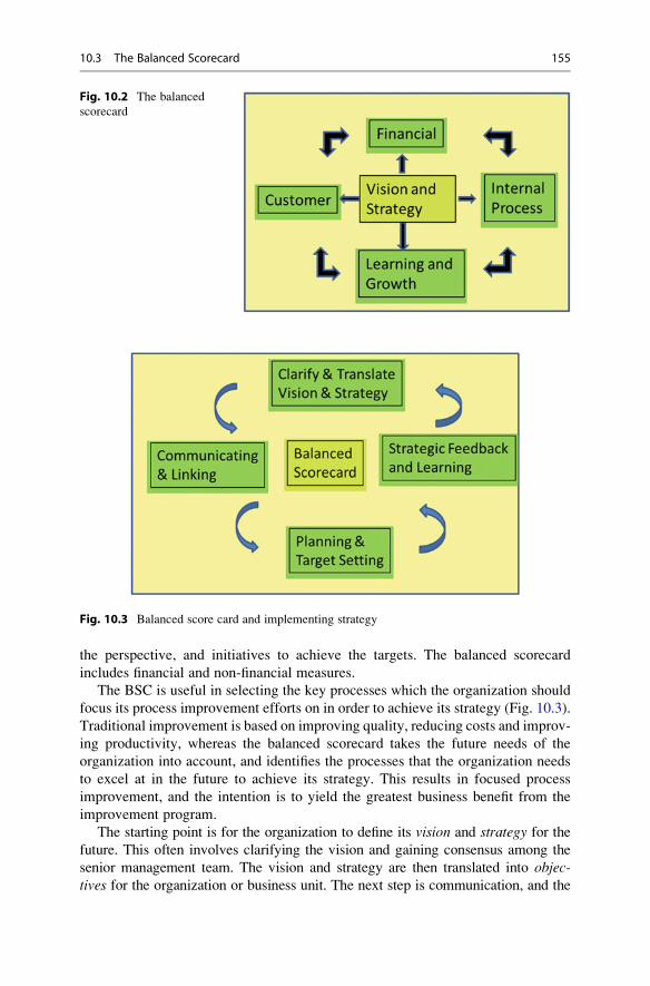
the perspective, and initiatives to achieve the targets. The balanced scorecard
includes financial and non-financial measures.
The BSC is useful in selecting the key processes which the organization should
focus its process improvement efforts on in order to achieve its strategy (Fig. 10.3).
Traditional improvement is based on improving quality, reducing costs and improv-
ing productivity, whereas the balanced scorecard takes the future needs of the
organization into account, and identifies the processes that the organization needs
to excel at in the future to achieve its strategy. This results in focused process
improvement, and the intention is to yield the greatest business benefit from the
improvement program.
The starting point is for the organization to define its vision and strategy for thefuture. This often involves clarifying the vision and gaining consensus among the
senior management team. The vision and strategy are then translated into objec-tives for the organization or business unit. The next step is communication, and the
Fig. 10.2 The balanced
scorecard
Fig. 10.3 Balanced score card and implementing strategy
10.3 The Balanced Scorecard 155

vision and strategy and objectives are communicated to all employees. These critical
objectives must be achieved in order for the strategy to succeed. All employees will
need to determine their own local objectives to support the organization strategy.
Goals are set and rewards are linked to performance measures.
The financial and customer objectives are first determined from the strategy, and
the key business processes to be improved are then identified. These are the key
processes that will lead to a breakthrough in performance for customers and
shareholders of the company. It may require new processes and this may require
re-training of employees on the new processes. The balanced scorecard is very
effective in driving organization change. The financial objectives require targets to
be set for customer, internal business process, and the learning and growth perspec-
tive. The learning and growth perspective will examine competencies and
capabilities of employees and the level of employee satisfaction. Figure 10.3
describes how the balanced scorecard may be used for implementing the organiza-
tion vision and strategy.
Table 10.1 presents sample objectives and measures for the four perspectives in
the BSC for an IT service organization.
10.4 Metrics for an Organization
The objective of this section is to define a set of metrics to provide visibility into
various areas in the organization, and to show how metrics can facilitate
improvements. Several examples of metrics that may assist an organization are
presented, and these may be applied or tailored to an individual organization.
Table 10.1 BSC objectives and measures for IT service organization
Financial Customer
Cost of provision of services Quality service
Cost of hardware/software Reliability of solution
Increase revenue Rapid response time
Reduce costs Accurate information
Timeliness of solution Timeliness of solution
99.999 % network availability 99.999 % network availability
24� 7 customer support 24� 7 customer support
Internal business process Learning and growth
Requirements elicitation Expertise of staff
Software design Software development capability
Implementation Project management
Testing Customer support
Maintenance Staff development career structure
Customer support Objectives for staff
Security/proprietary information Employee satisfaction
Disaster prevention and recovery Leadership
156 10 Software Metrics and Problem Solving

The objective is to give an overview of how metrics may be employed for effective
management, and many organizations have monthly quality or operation reviews in
which the presentation of metrics play a key part.
This section includes sample metrics for the various functional areas in a
software organization, including human resources, customer satisfaction, supplier
quality, internal audit, project management, requirements and development, testing,
and process improvement. These metrics are typically presented at a monthly
management review, and performance trends observed. The main output from a
management review is a series of actions to be completed by the following review.
10.4.1 Customer Satisfaction Metrics
Figure 10.4 shows the survey arrival rate per customer per month, and it indicates
that there is a customer satisfaction process in place in the organization, that the
customers are surveyed, and the extent to which they are surveyed. It does not
provide any information as to whether the customers are satisfied, whether any
follow-up activity from the survey is required, or whether the frequency of surveys
is sufficient for the organization.
Figure 10.5 gives the customer satisfaction measurements in several categories
including quality, the ability of the company to meet the committed dates and to
deliver the agreed content, the ease of use of the software, the expertise of the staff
and the value for money. Figure 10.5 is interpreted as follows:
7–10 Exceeds expectations
6–7 Meets expectations
5 Fair
0–4 Below expectations
Fig. 10.4 Customer survey arrivals
10.4 Metrics for an Organization 157

Another words, a score of 8 for quality indicates that the customers considers the
software to be of high quality, and a score of 9 for value for money indicates that the
customers considers the solution to be excellent value.
10.4.2 Process Improvement Metrics
The objective of process improvement metrics is to provide visibility into the
improvement program in the organization.
Figure 10.6 shows the arrival rate of improvement suggestions from the software
community. The chart indicates that initially the arrival rate is high and the closure
rate low, which is consistent with the commencement of a process improvement
program. The closure rate then improves which indicates that the improvement
team is active and acting upon the improvement suggestions. The closure rate is low
during July and August, which may be explained by the traditional holiday period.
The chart does not indicate the effectiveness of the process improvement
suggestions and the overall impact the particular suggestion has on quality, cycle
time, or productivity. There are no measurements included of the cost of performing
improvements, and this is important as the organization will need to be able to
compare the benefits of the improvement activities with the cost of the improvements.
Figure 10.7 provides visibility into the status of the improvement suggestions,
and the number of raised, open, and closed suggestions per month. The chart
indicates that gradual progress has been made in the improvement program with
a gradual increase in the number of suggestions that are closed.
Figure 10.8 provides visibility into the age of the improvement suggestions, and
indicates the effectiveness of the organization in acting on the them. It is a measure
of the productivity of the improvement team and its ability to do its assigned work.
Fig. 10.5 Customer satisfaction measurements
158 10 Software Metrics and Problem Solving

Figure 10.9 gives an indication of the productivity of the improvement
programme, and shows how often the team meets to discuss the improvement
suggestions and to act upon them. This chart is slightly naive as it just tracks the
number of improvement meetings which have taken place during the year, and
contains no information on the actual productivity of the meeting. The chart could
be considered with Fig. 10.6 to get a more accurate idea of productivity as the
number of closed improvement suggestions per month. There will usually be other
charts associated with an improvement program, for example, a metric to indicate
the status of the CMMI program is provided in Fig. 10.26. Similarly, a measure of
Fig. 10.6 Process improvement measurements
Fig. 10.7 Status of process improvement suggestions
10.4 Metrics for an Organization 159

the current status of an ISO 9000 implementation could be derived from the number
of actions which are required to implement ISO 9000, the number implemented,
and the number outstanding.
10.4.3 Human Resources and Training Metrics
These metrics give visibility into the human resources and training areas of a
company. They provide visibility into the current headcount (Fig. 10.10) of the
Fig. 10.8 Age of open process improvement suggestions
Fig. 10.9 Process improvement productivity
160 10 Software Metrics and Problem Solving

organization per calendar month and the turnover of staff in the organization
(Fig. 10.11). The human resources department will typically maintain measurements
of the number of job openings to be filled per month, the arrival rate of resumes per
month, the average number of interviews to fill one position, the percentage of
employees that have received their annual appraisal, etc.
The key goals of the HR department are defined and the questions and metrics
are associated with the key goals. For example, one of the key goals of the HR
department is to attract and retain the best employees, and this breaks down into the
two obvious sub-goals of attracting the best employees and retaining them.
Fig. 10.10 Employee headcount in current year
Fig. 10.11 Employee turnover in current year
10.4 Metrics for an Organization 161

The next chart gives visibility into the turnover of staff during the calendar year.
It indicates the effectiveness of staff retention in the organization.
10.4.4 Project Management Metrics
The goal of project management is to deliver a high-quality product that is fit for
purpose on time and on budget. The project management metrics provide visibility
into the effectiveness of the project manager in delivering the project on time, on
budget, and with the right quality.
The timeliness metric provides visibility into the extent to which the project has
been delivered on time (Fig. 10.12), and the number of months over or under
schedule per project in the organization is shown. The schedule timeliness metric
is a lagging measure, as it indicates that the project has been delivered within
schedule or not after the event.
The on-time delivery of a project requires that the various milestones in the
project be carefully tracked and corrective actions taken to address slippage in
milestones during the project.
The second metric provides visibility into the effort estimation accuracy of a
project (Fig. 10.13). Effort estimation is a key component in calculating the cost of
a project, and in preparing the schedule, and its accuracy is essential. We mentioned
the Standish Research data on projects in an earlier chapter, and this report showed
that accurate project estimation is difficult.
The effort estimation chart is similar to the schedule estimation chart, except that
the schedule metric is referring to time as recorded in elapsed calendar months,
whereas the effort estimation chart refers to the planned number of person months
required to carry out the work, and the actual number of person months that it took.
Fig. 10.12 Schedule timeliness metric
162 10 Software Metrics and Problem Solving

Projects need an estimation methodology to enable them to be successful in project
management, and the project manager will use historical data and metrics to
determine how accurate the estimation has actually been.
The next metric is related to the commitments which are made to the customer
with respect to the content of a particular release, and it indicates the effectiveness
of the projects in delivering the agreed requirements to the customer (Fig. 10.14).
This chart could be adapted to include enhancements or fixes promised to a
customer for a particular release of a software product.
Fig. 10.13 Effort timeliness metric
Fig. 10.14 Requirements delivered
10.4 Metrics for an Organization 163

10.4.5 Development Quality Metrics
These metrics give visibility into the development and testing of the software
product, and Chap. 7 presented several testing metrics. Figure 10.15 gives an
indication of the quality of the software produced and the stability of the
requirements. It shows the total number of defects and the total number of change
requests raised during the project, as well as details on their severities. The presence
of a large number of change requests suggests that there is room for improvement in
the requirements management process.
Figure 10.16 gives the status of open issues with the project which gives an
indication of the current quality of the project, and the effort required to achieve the
desired quality in the software. This chart is not used in isolation, as the project
manager will need to know the arrival rate of problems to determine the stability of
the software product.
The organization may decide to release a software product with open problems
provided that the associated risks can be managed. It is therefore important to
perform a risk assessment of the known problems to ensure that the product may
operate effectively. A work-around for each problem is typically included in a set of
release notes for the product.
The project manager will also need to know the age of the open problems, as this
will indicate the effectiveness of the team in resolving problems in a timely manner.
Figure 10.17 presents the age of the open defects and it highlights the fact that there
is one major problem that has been open for over 1 year. The project manager needs
to prevent this situation from arising, as critical and major problems need to be
addressed in a prompt and efficient manner.
The problem arrival rate (Fig. 10.18) is a key metric, and it enables the project
manager to judge the stability of the software, and this helps in judging whether the
Fig. 10.15 Total number of issues in project
164 10 Software Metrics and Problem Solving

software is fit for purpose and ready for release to potential customers. A sample
problem arrival chart is included here, and a preliminary analysis of the chart
indicates that the trend is positive, with the arrival rate of problems falling. The
project manager will need to do analysis to determine if there are other causes that
could contribute to the fall in the arrival rate; for example, it may be the case that
testing was completed in September, which would mean, in effect, that no testing
has been performed since then, with an inevitable fall in the number of problems
reported. The important point is not to jump to a conclusion based on a particular
Fig. 10.16 Open issues in project
Fig. 10.17 Age of open defects in project
10.4 Metrics for an Organization 165

chart, as the circumstances behind the chart must be fully known and taken into
account in order to draw valid inferences.
The next metric measures the effectiveness of the project in identifying defects
in the development phase (Fig. 10.19), and the effectiveness of the test groups in
detecting defects that are present in the software. The development portion typi-
cally includes defects reported on inspection forms and in unit testing.
The system testing is usually performed by an independent test group, and it may
include usability and performance testing. Acceptance testing is performed at the
customer site. The objective is that the number of defects reported at acceptance test
and after the product is officially released to customer should be minimal.
Fig. 10.18 Problem arrivals per month
Fig. 10.19 Phase containment effectiveness
166 10 Software Metrics and Problem Solving
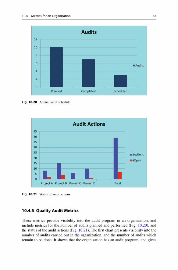
10.4.6 Quality Audit Metrics
These metrics provide visibility into the audit program in an organization, and
include metrics for the number of audits planned and performed (Fig. 10.20), and
the status of the audit actions (Fig. 10.21). The first chart presents visibility into the
number of audits carried out in the organization, and the number of audits which
remain to be done. It shows that the organization has an audit program, and gives
Fig. 10.20 Annual audit schedule
Fig. 10.21 Status of audit actions
10.4 Metrics for an Organization 167

information on the number of audits performed during a particular time period. The
chart does not give a breakdown into the type of audits performed, e.g., supplier
audits, project audits, and audits of particular departments in the organization, but it
could be adapted to provide this information.
The next chart gives an indication of the status of the various audits performed.
An audit is performed by an auditor, and the results are documented in an audit
report, and the audit actions need to be completed by the affected individuals and
groups. Figure 10.21 presents the status of the audit actions assigned to the affected
groups, and the actions need to be resolved in a timely manner.
Figure 10.22 gives visibility into the type of actions raised during the quality
audit of a particular area. The audit categories need to be defined by the organiza-
tion but could potentially include entry and exit criteria, planning issues, configu-
ration management issues, issues with compliance to the lifecycle or templates,
traceability to the requirements, issues with the review of various deliverables,
issues with testing, or process improvement suggestions.
10.4.7 Customer Care Metrics
The goals of the customer care group in an organization are to respond efficiently
and effectively to customer problems, to ensure that their customers receive the
highest standards of service from the company, and to ensure that its products
function reliably at the customer’s site. The organization will need to know its
efficiency in resolving customer queries, the number of customer queries, the
availability of its software systems at the customer site, and the age of open queries.
A customer query may result in a defect report in the case of a problem with the
software.
Fig. 10.22 Audit action types
168 10 Software Metrics and Problem Solving

Figure 10.23 could be developed further to include a severity attribute for the
query, and quantitative goals may be set for the resolution of queries (especially in
the case of service level agreements). The organization will often maintain a chart
for the age of open queries (similar to the chart in Fig. 10.17 presented earlier). The
organization will need to know the status of the backlog of open queries per month,
and a simple trend graph would provide this. Figure 10.23 shows the arrivals and
closures of queries: in the early part of the year the arrival rate exceeds the closure
rate of queries per month. This indicates an increasing backlog which needs to be
addressed.
The customer care department responds to any outages and ensures that the
outage time is kept to a minimum. Many companies set ambitious goals for network
availability: e.g., the “five nines initiative” has the objective of developing systems
which are available 99.999 % of the time, i.e., approximately 5 min of down time
per year. The calculation of availability is from the formula:
Availability ¼ MTBF
MTBFþMTTR
where the mean time between failure (MTBF) is the average length of time between
outages.
MTBF ¼ Sample Interval Time
#Outages
The formula for MTBF above is for a single system only, and the formula is
adjusted when there are multiple systems.
Fig. 10.23 Customer queries (arrivals/closures)
10.4 Metrics for an Organization 169

MTBF ¼ Sample Interval Time
#Outages�#Systems
The mean time to repair (MTTR) is the average length of time that it takes to
correct the outage, i.e., the average duration of the outages that have occurred, and it
is calculated from the following formula:
MTTR ¼ Total Outage Time
#Outages
Figure 10.24 presents outage information on the customers impacted by the
outage during the particular month, and the extent of the impact on the customer.
An effective customer care department will ensure that a post-mortem of the
outages is performed to ensure that lessons are learned to prevent a reoccurrence.
This causal analysis details the root causes of the outages and the actions to be taken
to prevent a reoccurrence. Metrics to record the amount of outage time per month
will typically be maintained by the customer care group in the form of a trend
graph.
Figure 10.25 provides visibility on the availability of the system at the customer
sites (as per the availability formula described earlier). Ambitious organizations are
designing systems to be available 99.999 % of the time.
10.4.8 Miscellaneous Metrics
Metrics may be applied to many other areas in the organization. This section
includes metrics on CMMI maturity in the organization and configuration manage-
ment. Figure 10.26 gives visibility into the time to create a software release from
the configuration management system.
Fig. 10.24 Outage time per customer
170 10 Software Metrics and Problem Solving

The internal CMMI maturity of the organization is given by Fig. 10.27, and
its current state of readiness for a formal CMMI assessment may be determined.
A numeric score of 1 to 10 is used to rate each process area and a score of 7 or above
indicates that the process area is satisfied.
Fig. 10.25 Availability of system per month
Fig. 10.26 Configuration management
10.4 Metrics for an Organization 171
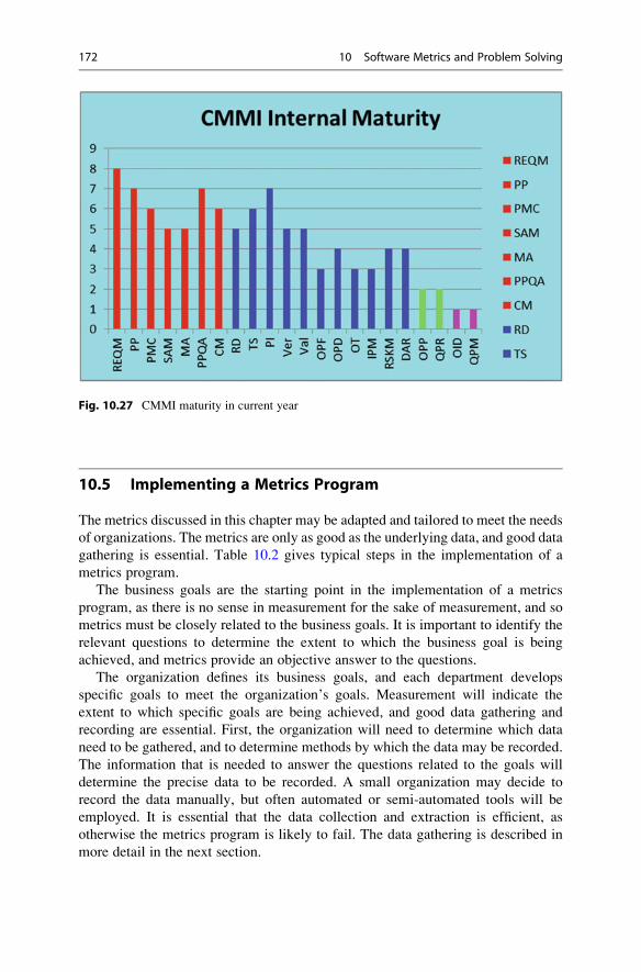
10.5 Implementing a Metrics Program
The metrics discussed in this chapter may be adapted and tailored to meet the needs
of organizations. The metrics are only as good as the underlying data, and good data
gathering is essential. Table 10.2 gives typical steps in the implementation of a
metrics program.
The business goals are the starting point in the implementation of a metrics
program, as there is no sense in measurement for the sake of measurement, and so
metrics must be closely related to the business goals. It is important to identify the
relevant questions to determine the extent to which the business goal is being
achieved, and metrics provide an objective answer to the questions.
The organization defines its business goals, and each department develops
specific goals to meet the organization’s goals. Measurement will indicate the
extent to which specific goals are being achieved, and good data gathering and
recording are essential. First, the organization will need to determine which data
need to be gathered, and to determine methods by which the data may be recorded.
The information that is needed to answer the questions related to the goals will
determine the precise data to be recorded. A small organization may decide to
record the data manually, but often automated or semi-automated tools will be
employed. It is essential that the data collection and extraction is efficient, as
otherwise the metrics program is likely to fail. The data gathering is described in
more detail in the next section.
Fig. 10.27 CMMI maturity in current year
172 10 Software Metrics and Problem Solving

The roles and responsibilities of staff will need to be defined with respect to the
implementation and day-to-day operation of the metrics program. Training is
needed to enable staff to perform their roles effectively. Finally, a regular manage-
ment review is needed, where the metrics and trends are presented, and actions
identified and carried out to ensure that the business goals are achieved.
10.5.1 Data Gathering for Metrics
Metrics are only as good as the underlying data, and so data gathering is a key
activity in a metrics program. The data to be recorded will be closely related to the
questions, and the data are used to give an objective answer to the question. The
starting point is the business goal (often quantitative for extra precision). Table 10.3
illustrates how the data to be gathered are identified in a top-down manner.
Table 10.4 is an approach to determine the effectiveness of the software devel-
opment process, and to enable the above questions to be answered. It includes a
column for inspection data which records the number of faults recorded at the
various inspections. The defects include the phase where the defect originated; forexample, a defect identified in the coding phase may have originated in the
requirements phase. The data is typically maintained in a spreadsheet, e.g., Excel,
and it needs to be kept up to date. It enables the phase containment effectiveness
(PCE) to be calculated for the various phases.
We will distinguish between a fault and a defect. A fault is a problem which isusually detected by a software inspection, and it is detected in the phase in which itis created. A defect is a problem which is detected out of phase, for example,
Table 10.2 Implementing
metricsImplementing metrics in organization
Define the business goals
Identify the pertinent questions
Define metrics
Identify tools to (semi-) automate metrics
Identify data that needs to be gathered.
Provide resources
Gather data and prepare metrics
Communicate the metrics and review monthly
Provide training
Table 10.3 Identifying data to be gathered
Goal Reduce escaped defects from each lifecycle phases by 10 %.
Questions How many faults are identified within each lifecycle phase?
How many defects are identified after each lifecycle phase is exited?
What % of defects escaped from each lifecycle phase?
10.5 Implementing a Metrics Program 173

a problem with the requirements may be discovered in the design phase, which is
out of the phase in which it was created.
For the example Table 10.4, the effectiveness of the requirements phase is
judged by its success in identifying defects as early as possible, as the cost of
correction of a requirements defect increases the later in the cycle that it is
identified. The requirements PCE is calculated to be 40 %, i.e., the total number
of faults identified in phase divided by the total number of faults and defects
identified. There were four faults identified at the inspection of the requirements,
and six defects were identified: one at the design phase, one at the coding phase, two
at the unit testing phase, and two at the system testing phase: i.e., 4/10¼ 40 %.
Similarly, the code PCE is calculated to be 57 %.
The overall PCE for the project is calculated to be the total number of faults
detected in phase in the project divided by the total number of faults and defects,
i.e., 27/52¼ 52 %. Table 10.4 is a summary of the collected data and consists of:
• Maintain inspection data of requirements, design and code inspections
• Identify defects in each phase and determine their phase of origin
• Record the number of defects in each phase per phase of origin.
The staff who perform inspections need to record the problems identified,
whether it is a fault or a defect, and its phase of origin. Staff will need to be
appropriately trained to do this consistently.
Table 10.4 is just one example of data gathering, and in practice the organization
will need to collect various data to enable it to give an objective answer to the extent
that the particular goal is being satisfied.
10.6 Problem-Solving Techniques
Problem solving is a key part of quality improvement, and a quality circle (or
problem-solving team) is a group of employees who do similar work and volunteer
to come together on company time to identify and analyse work-related problems.
Quality circles were first proposed by Ishikawa in Japan in the 1960s. Various tools
that assist problem solving include process mapping, trend charts, bar charts, scatter
Table 10.4 Phase containment effectiveness
Phase of origin
Phase
Inspect
faults Reqs Design Code
Accept
test
Total
faults
Total
defects % PCE
Reqs 4 1 1 4 6 40 %
Design 3 3 4 42 %
Code 20 20 15 57 %
Unit test 2 2 10
System test 2 2 5
Accept test
174 10 Software Metrics and Problem Solving

diagrams, fishbone diagrams, histograms, control charts, and pareto charts [9]. Theseprovide visibility into the problem and help to quantify the extent of the problem. The
main features of a problem-solving team include:
• Group of employees who do similar work
• Voluntarily meet regularly on company time
• Supervisor as leader
• Identify and analyse work-related problems
• Recommend solutions to management
• Implement solution where possible
The facilitator of the quality circle coordinates the activities, ensures that the
team leaders and teams members receive sufficient training, and obtains specialist
help where required. The quality circle facilitator has the following responsibilities:
• Focal point of quality circle activities
• Train circle leaders/members
• Coordinate activities of all the circle groups
• Assist in inter-circle investigations
• Obtain specialist help when required
The circle leaders receive training in problem-solving techniques, and are
responsible for training the team members. The leader needs to keep the meeting
focused and requires skills in team building. The steps in problem solving include:
• Select the problem
• State and restate the problem
• Collect the facts
• Brainstorm
• Choose course of action
• Present to management
• Measurement of success
The benefits of a successful problem solving culture in the organization include:
• Savings of time and money
• Increased productivity
• Reduced defects
• Fire prevention culture
Various problem-solving tools are discussed in the following sections.
10.6.1 Fishbone Diagram
This well-known problem-solving tool consists of a cause and effect diagram that is
in the shape of the backbone of a fish. The objective is to identify the various causes
of some particular effect, and then these various causes are broken down into a
number of sub-causes. The various causes and sub-causes are analysed to determine
the root cause of the particular effect, and actions to address the root cause are then
defined to prevent a reoccurrence of the manifested effect. There are various
categories of causes and these may include people, methods and tools, and training.
10.6 Problem-Solving Techniques 175

The great advantage of the fishbone diagram is that it offers a crisp mechanism to
summarize the collective knowledge that a team has about a particular problem, as
it focuses on the causes of the problem, and facilitates the detailed exploration of
the causes.
The construction of a fishbone diagram involves a clear statement of the partic-
ular effect, and the effect is placed at the right-hand side of the diagram. The major
categories of cause are drawn on the backbone of the fishbone diagram; brainstorm-
ing is used to identify causes; and these are then placed in the appropriate category.
For each cause identified the various sub-causes may be identified by asking the
question “Why does this happen?” This leads to a more detailed understanding of
the causes for a particular effect.
Example 10.1
An organization wishes to determine the causes of a high number of customer
reported defects. There are various categories which may be employed such as
people, training, methods, tools, and environment. In practice, the fishbone
diagram in Fig. 10.28 would be more detailed than that presented, as
sub-causes would also be identified by a detailed examination of the identified
causes. The root cause(s) are determined from detailed analysis.
This example suggests that the organization has significant work to do in several
areas, and that an improvement program is required. The improvements needed
include the implementation of a software development process and a software test
process; the provision of training to enable staff to do their jobs more effectively;
and the implementation of better management practices to motivate staff and to
provide a supportive environment for software development.
The causes identifiedmay be symptoms rather than actual root causes: for example,
high staff turnover may be the result of poor morale and a “blame culture”, rather than
Fig. 10.28 Fishbone cause-and-effect diagram
176 10 Software Metrics and Problem Solving

a cause in itself of poor quality software. The fishbone diagram gives a better
understanding of the possible causes of the high number of customer defects.
A small subset of these causes is then identified as the root cause(s) of the problem
following further discussion and analysis.
The root causes are then addressed (e.g., an appropriate software development
process and test process are defined and providing training to all development staff on
the new processes). The management attitude and organization culture will need to be
corrected to enable a supportive software development environment to be put in place.
10.6.2 Histograms
A histogram is a way of representing data in bar chart format, and it shows the relative
frequency of various data values or ranges of data values. It is typically employed
when there are a large number of data values, and it gives a very crisp picture of the
spread of the data values, and the centring and variance from the mean.
The histogram has an associated shape; e.g., it may be a normal distribution, abimodal or multi-modal distribution, or be positively or negatively skewed. The
variation and centring refer to the spread of data, and the relation of the centre of the
histogram to the customer requirements. The spread of the data is important as it
indicates whether the process is variable or whether it is performing within the
requirements. The histogram is termed process centred if its centre coincides with
the customer requirements; otherwise the process is too high or too low. A histo-
gram enables predictions of future performance to be made, assuming that the
future will reflect the past.
The construction of a histogram first requires that a frequency table be
constructed, and this requires that the range of data values be determined. The
data are divided into a number of data buckets, where a bucket is a particular range
of data values, and the relative frequency of each bucket is displayed in bar format.
The number of class intervals or buckets is determined, and the class intervals are
defined. The class intervals are mutually disjoint and span the range of the data
values. Each data value belongs to exactly one class interval and the frequency of
each class interval is determined.
The histogram is a well-known statistical tool and its construction is made more
concrete with the following example.
Example 10.2
An organization wishes to characterize the behaviour of the process for the
resolution of customer queries in order to achieve its customer satisfaction goal.
Goal
Resolve all customer queries within 24 h.
Question
How effective is the current customer query resolution process?
What action is required (if any) to achieve this goal?
10.6 Problem-Solving Techniques 177

The data class size for the histogram in Fig. 10.29 is 6 h, and data class sizes
are the same for standard histograms, whereas the size may be different for
non-standard histograms. The sample mean is 19 h in this example.
This histogram (Fig. 10.29) is based on query resolution data from 36 samples.
The organization goal of customer resolution of all queries within 24 h is not met,
and the goal is satisfied in (25/36¼ 70 % for this particular sample).
Further analysis is needed to determine the reasons why 30 % of the goals are
outside the target 24-h time period. It may prove to be impossible to meet the goal
for all queries, and the organization may need to refine the goal to state that instead
all critical and major queries will be resolved within 24 h.
10.6.3 Pareto Chart
The objective of a pareto chart is to identify and focus on the resolution of problems
that have the greatest impact, as often 20 % of the causes are responsible for 80 %of the problems. The problems are classified into various categories, and the
frequency of each category of problem is determined. The chart is displayed in a
descending sequence of frequency, with the most significant cause presented first,
and the least significant cause presented last.
It is a key problem-solving tool, and a properly constructed pareto chart will
allow the organization to resolve the key causes of problems, and to verify their
resolution. The success of the improvements may be determined at a later stage
from an analysis of the new problems and creating a new pareto chart. The result
should show tangible improvements.
Fig. 10.29 Histogram
178 10 Software Metrics and Problem Solving
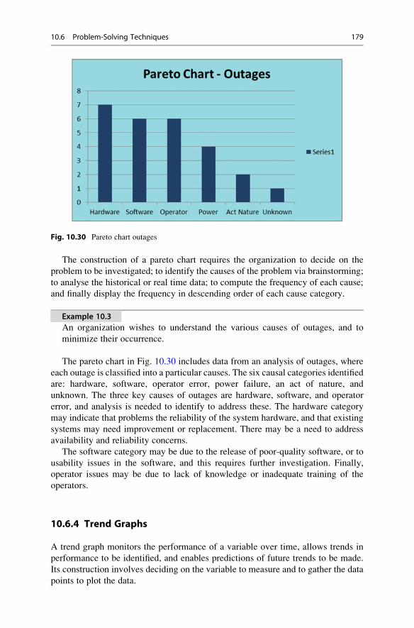
The construction of a pareto chart requires the organization to decide on the
problem to be investigated; to identify the causes of the problem via brainstorming;
to analyse the historical or real time data; to compute the frequency of each cause;
and finally display the frequency in descending order of each cause category.
Example 10.3
An organization wishes to understand the various causes of outages, and to
minimize their occurrence.
The pareto chart in Fig. 10.30 includes data from an analysis of outages, where
each outage is classified into a particular causes. The six causal categories identified
are: hardware, software, operator error, power failure, an act of nature, and
unknown. The three key causes of outages are hardware, software, and operator
error, and analysis is needed to identify to address these. The hardware category
may indicate that problems the reliability of the system hardware, and that existing
systems may need improvement or replacement. There may be a need to address
availability and reliability concerns.
The software category may be due to the release of poor-quality software, or to
usability issues in the software, and this requires further investigation. Finally,
operator issues may be due to lack of knowledge or inadequate training of the
operators.
10.6.4 Trend Graphs
A trend graph monitors the performance of a variable over time, allows trends in
performance to be identified, and enables predictions of future trends to be made.
Its construction involves deciding on the variable to measure and to gather the data
points to plot the data.
Fig. 10.30 Pareto chart outages
10.6 Problem-Solving Techniques 179

Example 10.4
An organization plans to deploy an enhanced estimation process, and wishes to
determine if estimation is actually improving.
The estimation accuracy determines the extent to which the actual effort differs
from the estimated effort. A reading of 25 % indicates that the project effort was
25 % more than estimated, whereas a reading of �10 % indicates that the actual
effort was 10 % less than estimated. The trend chart (Fig. 10.31) indicates that
initially that estimation accuracy is very poor, but then there is a gradual improve-
ment coinciding with the implementation of the new estimation process.
It is important to analyse the performance trends in the chart. For example, the
estimation accuracy for August (17 % in the chart) needs to be investigated to
determine the reasons why it occurred. It could potentially indicate that a project is
using the old estimation process or that a new project manager received no training.
A trend graph is useful for noting positive or negative trends in performance;
negative trends are analysed and actions identified to correct performance.
10.6.5 Scatter Graphs
The scatter diagram is used to measure the relationship between two variables, and to
determine whether there is a relationship or correlation between the variables.
The results may be a positive correlation, negative correlation, or no correlation.
Correlation has a precise statistical definition, and it provides a precise mathematical
understanding of the extent to which the two variables are related or unrelated.
Fig. 10.31 Trend chart estimation accuracy
180 10 Software Metrics and Problem Solving

The scatter graph provides a graphical way to determine the extent that two
particular variables are related, and it may be used to determine if there a connec-
tion between an identified causes and the effect.
The construction of a scatter diagram requires the collection of paired samples
of data, and the drawing of one variable as the x-axis, and the other as the y-axis.The data are then plotted and interpreted.
Example 10.5
An organization wishes to determine if there is a relationship between the
inspection rate and the error density of defects identified.
The scatter graph (Fig. 10.32) provides evidence for the hypothesis that there is a
relationship between the lines of code inspected and the error density recorded (per
KLOC). The graph suggests that the error density of defects identified during
inspections is low if the speed of inspection is too fast, and the error density is
high if the speed of inspection is below 300 lines of code per hour. A line can be
drawn through the data which indicates a linear relationship.
10.6.6 Metrics and Statistical Process Control
The principles of statistical process control were described in an earlier chapter, and
process performance is measured and controlled within upper and lower control
limits. Figure 10.33 presents an example on breakthrough in performance of an
estimation process, and is adapted from [35].
Fig. 10.32 Scatter graph amount inspected rate/error density
10.6 Problem-Solving Techniques 181

The initial upper and lower control limits for estimation accuracy are set at
�40 %, and the performance of the process is within the defined upper and control
limits. However, the organization will wish to improve its estimation accuracy and
this leads to the organization’s revising the upper and lower control limits to
�25 %. The organization will need to analyse the slippage data to determine the
reasons for the wide variance in the estimation, and part of the solution will be the
use of enhanced estimation methods in the organization. In this chart, the organiza-
tion succeeds in performing within the revised control limit of�25 %, and the limit
is revised again to�15 %. This requires further analysis to determine the causes for
slippage and further improvement actions are needed to ensure that the organization
performs within the �15 % control limit.
10.7 Review Questions
1. Describe the Goal, Question, Metric model.
2. Explain how the Balanced Scorecard may be used in the implementation
of organization strategy.
3. Describe various problem solving techniques.
4. What is a fishbone diagram?
5. What is a histogram? A Pareto Chart?
6. What is a scatter graph?
7. Discuss how a metrics programme may be implemented.
8. What is statistical process control?
Fig. 10.33 Estimation accuracy and control charts
182 10 Software Metrics and Problem Solving

10.8 Summary
Measurement is an essential part of mathematics and the physical sciences, and has
been successfully applied in recent years to the software engineering discipline. The
purpose of a measurement program is to establish and use quantitative measurements
to manage software development environment in the organization, to assist the
organization in understanding its current software capability, and to provide an
objective indication that improvements have been successful. This chapter included
a collection of sample metrics to give visibility into the various functional areas in the
organization, including customer satisfaction metrics, process improvement metrics,
project management metrics, HR metrics, development and quality metrics, and
customer care metrics.
The balanced scorecard assists the organization in selecting appropriate measure-
ments to indicate the success or failure of the organization’s strategy. Each of the four
scorecard perspectives includes objectives that need to be achieved for the strategy to
succeed, and measurements indicate the extent to which the objectives are being met.
The Goal, Question, Metric paradigm is a rigorous, goal-oriented approach to
measurement in which goals, questions, and measurements are closely integrated.
The business goals are first defined, and then questions that relate to the achieve-
ment of the goal are identified, and for each question a metric that gives an objective
answer to the particular question is defined.
Metrics play a key role in problem solving, and various problem solving
techniques were discussed. These include histograms, pareto charts, trend charts
and scatter graphs. The measurement data are used to assist the analysis and to
determine the root cause of a particular problem, and to verify that the actions taken
to correct the problem have been effective. They allow trends to be seen over time,
and the analysis of the trends allows action plans to be prepared and implemented
for continuous improvement.
Metrics may be employed to track the quality, timeliness, cost, schedule, and
effort of software projects. They provide an internal view of the quality of the
software product, but care is needed before deducing the behaviour that a product
will exhibit externally.
10.8 Summary 183

ISO 9000 11
Key Topics
Quality Management System
ISO 9001 and ISO 9004
Customer Satisfaction
Customer Requirements
Implementing ISO 9000
Continuous Improvement
Measurement and Analysis
Self-Assessment Methodology
11.1 Introduction
ISO 9000 is a widely employed quality management standard, and it was developed
by the International Standards Organization (ISO). The standard was influenced by
the British quality standard (BS 5750), and it was originally published as a standard
in 1987, and revised in 1994, 2000 and in 2008.
The ISO 9000 family of standards may be applied to various types of organiza-
tions, including manufacturing, software and service organizations. The achieve-
ment of ISO 9001 by a company typically indicates that the company has a sound
quality system in place, and that quality and customer satisfaction are core values of
the company. ISO 9001 is regarded as a minimal standard that an organization
which takes quality seriously should satisfy, and many organizations require their
subcontractors to be ISO 9001 certified.
G. O’Regan, Introduction to Software Quality, Undergraduate Topicsin Computer Science, DOI 10.1007/978-3-319-06106-1_11,# Springer International Publishing Switzerland 2014
185

It arose due to the need by organizations to know the capability or maturity of
their subcontractors prior to selection. The existing approach was to assess the
capability of a potential supplier prior to its selection. This generally involved a
quality representative from the organization visited the proposed subcontractor, and
assessing its process maturity. This was expensive and time consuming, especially
if the organization had many subcontractors. Once the international standard
became available, it allowed the organization to place ISO 9001 certification as a
minimum requirement on the subcontractor, and thereby to expect certain minimal
quality standards from the subcontractor. ISO 9001 became a discriminator in the
selection of a contractor, and the certification provided confidence in the contractor
to deliver a high-quality solution.
The standard places requirements on the quality management system of the
company, but it allows the company to choose how it may satisfy the requirements.
The ISO requirements include controls, processes and procedures, and the mainte-
nance of quality records as evidence.
11.2 Motivation for ISO 9000
The ISO 9000 family of standards offers a structured way for a company to
improve, and the company can focus its initial improvements to those clauses that
will yield the greatest business benefit. Then as the company increases in maturity,
the other clauses in the standard may be implemented. A standard is a useful way to
show the organization how good it actually is, and to prioritize further improve-
ments. Table 11.1 provides some reasons for the company to embark on an ISO
9000 initiative.
Table 11.1 Motivation
for ISO 9000
implementation
Enhances credibility of the company
Marketing benefit of ISO 9000
Shows commitment to quality and customer satisfaction
Shows commitment to continuous improvement
Provides a framework for improvement
Shows that a fire prevention culture is in place
Less rework of defective products
Reduced cost of poor quality
Improved productivity due to less rework
Improved morale
A more effective organization
186 11 ISO 9000

11.3 ISO 9000
The ISO 9000 family of standards consists of three standards: namely ISO 9000,
ISO 9001, and ISO 9004. The ISO 9000 standard covers the fundamentals and
vocabulary of quality management systems.
The ISO 9001 standard specifies the requirements of a quality management
system, and applies to manufacturing, software, and service organizations. It details
the requirements which the quality management system of the organization must
satisfy to be ISO 9001 compliant. There is a simple process model defined in the
standard, and there is an emphasis on measurement, continual improvement, and
customer satisfaction. There are five clauses in the new standard, and the standard is
customer focused.
The ISO 9004 standard (Managing for the Sustained Success of the Organi-
zation) provides guidance for performance improvement, and it is helpful in
assisting organizations in the implementation of ISO 9001. It includes a simple
self-assessment methodology to allow the organization to determine its current
maturity with respect to ISO 9001. There are five main clauses in ISO 9001 standard
(Table 11.2), with each clause having several sub-clauses.
The objective is to determine the customer requirements; to develop a product
which satisfies the requirements, and which matches or exceeds customer expecta-
tions; and to continually improve to serve the customer better. Figure 11.1 describes
the interaction between the various ISO 9001 clauses.
11.3.1 Quality Management System
This clause is concerned with documenting and implementing the quality mana-
gement system (Fig. 11.1), and defining the procedures required by the standard.
The procedures required include the quality manual, and procedures for the control
of documents and the control of quality records.
Table 11.2 ISO 9001 clauses
Clause Description
Quality Management System This clause refers to the documentation and implementation
of the Quality Management System (QMS)
Resource Management This is concerned with the provision of the resources required
to implement the QMS.
Product or Service
Realisation
This is concerned with the provision of processes to implement
the product or service.
Management Responsibility This is concerned with defining the responsibilities of management
in implementing the quality system.
Measurement, Analysis and
Improvement
This is concerned with the establishment of a measurement
programme, and using measures for continuous improvement.
11.3 ISO 9000 187

The clause is also concerned with the control of quality records, as these are
used to provide evidence of conformity to the quality system. The sub-clauses
include general requirements of the quality management system, documentation
requirements and the use of quality management principles in the organization.
The procedures required include:
– Quality Manual
– Control of Documents
– Control of records
– Internal Audit
– Control of Non-conforming product
– Corrective Action Procedure
– Preventive Action Procedure.
There is more than one way to implement the specified ISO 9001 requirements,
and the organization needs to choose an implementation which is tailored to its
own needs.
The quality manual is a key document in the QMS, and it will provide details of
the quality policy, the key goals and initiatives of the organization to achieve
customer satisfaction, an organization chart to show where quality fits into the
organization, and so on. The quality manual is one of the first things that an ISO
9001 auditor will examine, as it shows how the quality management system has
been implemented.
The control of documents requires the definition of a document control proce-
dure, which specifies the layout of a document, including its version number,
revision history, its current status, and so on. Quality records provide evidence
that the quality system and associated processes are being consistently performed,
Fig. 11.1 ISO 9000 quality management system
188 11 ISO 9000

and the control of records procedure defines the records that will be maintained,
the length of time that they will be maintained for, the means by which they are
maintained, and so on. The records may include minutes and actions from manage-
ment reviews, training records, records from the reviews of project deliverables,
records from testing, records from audits, and so on.
11.3.2 Management Responsibility
The commitment of management is fundamental to the success of the QMS, and
management play a key role in creating an environment in which the quality
management system can operate effectively in the organization. Management
need to promote quality, customer satisfaction and continuous improvement, and
this clause defines the responsibilities of management in the quality system.
It includes defining and communicating the quality policy, planning for quality,
setting quality objectives, defining a quality policy, and participating in reviews of
the quality management system. It consists of the following sub-clauses:
– Management Commitment
– Customer Focus
– Defining Quality Policy and Quality Manual
– Planning and setting quality objectives
– Responsibility, Authority and Communication
– Management Review
Management and staff need to focus on the customers and on customer satisfaction.
They need to identify customers’ needs and expectations, and to make customer
satisfaction a core value of the organization.
The quality policy expresses the core values of the company on quality, cus-
tomer satisfaction and continuous improvement. Management needs to communi-
cate the quality policy and quality expectations, and all employees need to actively
implement the policy. The quality policy needs to be reviewed periodically to
ensure that it continues to meet the needs of the organization.
Management is responsible for quality planning in the organization, and the
quality policy is employed to set the quality objectives (usually quantitative) for the
organization. For example, the objectives may be to deliver 100 % of the projects
on time and on budget; achieve a customer satisfaction measure in excess of 8.1;
and resolve 100 % of critical problems within 24 h. The quality planning may also
involve defining several high-quality processes such as a software development
process and a project management process. These processes will allow high-quality
software to be delivered on time and on budget.
Management needs to assign responsibility and authority to people to implement
and maintain the quality system. Management is responsible for approving the
quality system, monitoring it for effectiveness, and improving it. The responsibility
of the different roles in the process is defined, and management will monitor
process performance, and take corrective action when performance deviates from
11.3 ISO 9000 189
expectations. The organization will have a quality manager (this may be a part time
role for smaller organizations).
Management will review the quality system at regular intervals to ensure its
effectiveness. The quality review will examine the various parts of the quality
system such as customer satisfaction, human resources and training, project man-
agement, development and test, customer support, process improvement, quality
audits, and so on. Each group has an allocated period of time to provide visibility
into their area, and this enables management to examine trends in the performance
of the quality system, and to identify improvements. Actions to resolve any
identified issues are assigned to groups and individuals. The management review
is often metrics driven as this provides objective facts, and the review is often
chaired by the quality manager, and attended by management in the organization.
11.3.3 Resource Management
Resource management is concerned with ensuring that the appropriate resources are
in place to deliver high quality software, and this includes the human resources,
training, the work environment and the physical infrastructure. It consists of the
following sub-clauses:
– Provision of Resources
– Human Resources
– Infrastructure
– Work Environment
The provision of resources is the process concerned with determining the resources
needed to implement the quality management system, and providing them. The
resources include people, buildings, computers, and so on, and the organization
needs to plan for future resource needs, as well as its current needs. The organiza-
tion needs to enhance the knowledge and competence of people by education and
training, and to develop leadership skills for future managers.
The human resource function plays a strategic role in the organization. It is
responsible for staff recruitment and retention, career planning for employees,
employee appraisals, health and safety, training in the organization, and providing
a pleasant working environment. It facilitates communication between manage-
ment and staff.
The responsibilities and skills required for the various roles in the organization
need to be defined, and training identified to address any gaps in the current
qualification, skills and experience of the employees and the roles which they are
performing. An annual organization training plan is often prepared, and the plan is
updated throughout the year. There may be mandatory training for employees on
key areas, e.g., on quality. The training needs of the organization may change
during the year due to changes in the technologies and processes employed, or due
to a change in the strategic direction of the organization.
The organization needs to have a process for defining the appropriate infra-
structure for efficient product realization, and this includes buildings, furniture,
190 11 ISO 9000

office equipment, computer hardware and software, technologies, and tools.
The infrastructure plan is prepared well in advance, and is updated in a controlled
manner in response to medium and short-term needs. It supports the organization in
achieving its strategic goals and customer satisfaction. The infrastructure needs to
be maintained to ensure that it continues to meet the needs of the organization.
The organization needs a disaster management plan to identify preventive
measures to prevent disasters from happening, and a disaster recovery procedure
to minimize disruption following an actual disaster. The actual recovery steps
depend on the scale of damage, and it is essential that the recovery is planned
with clearly defined roles and responsibilities. The individuals with responsibility
for disaster prevention and recovery need to be trained in their roles, and the plan
needs to be tested to ensure its effectiveness in the case of a real disaster. The
damage assessment team assesses the actual damage, and the damage recovery
team is responsible for responding to the disaster.
The organization needs to develop a work environment that will promote
employee satisfaction, motivation and performance.
11.3.4 Product or Service Realization
This is concerned with the provision of efficient processes for product or service
realization to ensure that the organization has the capability to develop products or
services that will meet customer expectations. It may involve developing processes
for defining and managing the requirements; processes for design and development;
processes for testing; a process for project management; a change management
process; and so on. It involves the following sub-clauses:
– Planning of product realization
– Customer related processes
– Customer requirements
– Customer communication
– Design and development
– Control of changes
– Purchasing process (information and verification)
– Production and service provision
– Validation of processes
– Identification and traceability
– Customer property
– Preservation of product
– Control of measuring and monitoring devices
The planning of product realization requires the organization to plan and
define the processes needed for product realization. This requires a sound project
management process as well as an effective software development process to
identify the customer requirements and to design and develop an appropriate
solution that will satisfy the customer’s expectations. It will require other processes
such as a change management process and a testing process.
11.3 ISO 9000 191
The customer related processes are concerned with processes for defining
customer requirements; managing customer requirements; and verifying and
validating customer requirements to ensure customer satisfaction. There is also a
need for an effective communication mechanism where customer feedback
(enquiries and complaints) may be made and a process to determine the level of
customer satisfaction.
The customer requirements are the foundation for the product, and these need
to be correct before design and development commences. The requirements are
documented, and reviewed by all stakeholders to ensure that they are correct
and reflect the customer’s needs.
The design and development process needs to be defined and capable of delive-
ring high-quality software on time to the customer. It involves design and develop-
ment planning, the design of the solution, a review of the design and development,
verification and validation of design and development, and control of changes
during design and development. There will be controls in the process to ensure
that the defined deliverable are produced, reviewed and approved at key milestones,
and to ensure that the requirements have been properly implemented.
The importance of reviews of design and development activities is evident
from Chap. 6 on software inspections, and reviews enable defects to be identified
earlier and help to reduce the cost of poor quality. The verification and validation
activities are concerned with “building it right” and “building the right product” asdiscussed in Chap. 4. A traceability matrix may also be employed for verification
and validation, as well as reviews and the various types of testing as discussed
previously. There is a need for a change control process to manage changes to the
requirements, and to keep all the deliverables consistent with the requirements.
This has been described in Chap. 5 on configuration management.
The purchasing process is important as a product often is built from components
that are procured from one or more suppliers. Therefore, the purchased products or
components need to be fit for purpose, and this involves verification (by testing
or inspections) that the purchased products satisfy the purchase requirements.
The capability of the supplier needs to be clearly understood, and this may involve
a formal evaluation of the supplier capability as discussed in Chap. 8. Outsourcing
is often employed in the software sector, and it is important to select a supplier with
the capability to deliver a high-quality solution on time and on budget.
There are ISO 9001 requirements for planning and carrying out production and
service provision under controlled conditions; validating production and service
provision processes; establishing a process for identification and traceability;
handling customer property correctly; and preserving the product. These need to
be interpreted to a software organization, and efficient and reliable processes are
essential to producing high-quality software. The production of software involves
the definition of the content of a release, performing a release build to produce the
executable files, and the storage of the released software on electronic media such
as a CD or floppy disk.
Identification and traceability requires a sound configuration management system
which includes document change control, software source code control management,
192 11 ISO 9000

change control management, and release builds. The released software is usually
accompanied by release notes and an installation guide. The validation of processes
for production and service is addressed by audits of processes and products, and
quantitative measurement of processes.
The contents of a release and the versions of the source files which make up the
release should be known, as well as notes to specify the defects corrected and
enhancements implemented. A product in the manufacturing field is composed of
many components, which are provided by various suppliers. It is important that the
constituents of each product be fully known and traceable, as if it is discovered
that a batch of components which has been used in the manufacture of a product
contains defective items, it may be necessary to recall all products which have
been manufactured with components from this particular batch. Consequently, the
product must be clearly identified and traceable.
The customer property sub-clause requires the organization to exercise care
with customer property while it is under the organization’s control. This requires
the organization to identify all customer property and to verify and protect it.
This could potentially include confidential information, intellectual property, and
test data. The software organization may have access to the customer computer
network, and must handle the network with the utmost care and confidentiality.
The preservation of product clause requires the organization to have imple-
mented processes for handling, storage, packaging, and delivery of the product.
The implementation for a software organization usually requires that the software
be stored on electronic media and packaged and delivered to the customer.
The control of measuring and monitoring devices is important in the manufa-
cturing sector, and regular calibration of the machines is required to ensure correct
performance. For a software organization this is interpreted to the testing environ-
ment, the test tools and test scripts, and automated testing.
11.3.5 Measuring, Analysis, and Improvement
This clause is concerned with the measurement of processes to improve the perfor-
mance of the quality management system. It involves the analysis of data to plan
improvement actions, and to verify that the improvements have been effective.
Measurement provides objective data on the effectiveness of the quality system,
and detailed analysis using problem-solving techniques is done to identify the key
issues, and to define improvement actions. It includes the following sub-clauses:
– Measurement of customer satisfaction
– Internal audits
– Measurement and monitoring of processes
– Measurement and monitoring of product
– Control of nonconformity
– Analysis of data
– Continual improvement
– Corrective action
– Preventative action
11.3 ISO 9000 193

The measurement of customer satisfaction is important, as the goal is to develop
a high-quality product that will satisfy the customer. A customer satisfaction survey
(as discussed in an earlier chapter) is often employed to measure the level of
satisfaction, as well as monitoring customer problems and complaints. The feed-
back from the survey is discussed with the customer, and an action plan is prepared
to address any issues. The monitoring of customer satisfaction will indicate the
success of the organization in satisfying its customers.
The organization needs to establish an internal audit process, and the objective
of an audit is to provide visibility to management on the processes being used and
the product being built. The audit is an independent examination, and is typically
carried out by a trained auditor. The level of compliance to the defined process is
considered, as is the effectiveness of the defined process. Improvement oppor-
tunities are identified and tracked to completion. The output from the audit is an
audit report, and the audit report includes the findings of the audit and recom-
mendations. Audits were discussed in Chap. 9.
The measurement and monitoring of processes requires the organization to
implement measurements to evaluate process performance. Process measurement
is essential in a manufacturing environment, and process measurement in a software
organization is focused on measuring key software processes. Quantitative goals
are set for the performance of key processes, and actual results compared against
the objectives. There is more information for software organizations in the discus-
sion of CMMI level 4 discussed in Chap. 13. The idea is that if process performance
falls outside the control limits, then this will trigger corrective actions to adjust the
performance of the process to ensure that it performs within the upper and lower
control limits. This is best seen with a process performance diagram (e.g., Fig. 1.2).
The measurement and monitoring of a product is performed to verify that the
product requirements are fulfilled. This enables an objective decision to be made on
whether it is appropriate to release the software to potential customers. It may
involve specifying various quantitative goals to be satisfied prior to release.
The control of nonconformity is concerned with the procedure for repor-
ting defects, and taking action to correct the defect. The defects are often
recorded with a defect reporting tool or a spreadsheet, and relevant information
recorded. This includes the severity of the defect, its description, the date that it
occurred, the technical person responsible for its correction, the type of defect, and
so on. The quality status of the project includes the open defects, and the most
serious defects need to be resolved prior to release of the software.
The analysis of data is used in decision making, and the organization needs
to analyse the data to determine the appropriate actions for improvement. The
objective of continual improvement is to improve the effectiveness of the quality
management system through the use of the quality policy, quality objectives, audit
results, customer satisfaction measurements, management review, analysis of data,
and corrective and preventive actions.
Corrective action is taken on customer complaints, defect reports, audit reports,
etc., and the results lead to a more effective QMS. It involves analysis of the
identified issues or defects, with actions defined to address, and the effectiveness
of the actions periodically reviewed. The objective of preventive action is to
194 11 ISO 9000

identify actions to prevent potential defects from occurring. This requires analysis
to determine the causes of defects, identifying actions to be taken, implementing
the actions, and periodically reviewing the effectiveness of the actions.
11.4 Implementing ISO 9001
The implementation of ISO 9001 in an organization is closely related to the
activities described in Sects. 11.3.1, 11.3.2, 11.3.3, 11.3.4, and 11.3.5. ISO 9001
is implemented to improve quality and customer satisfaction, and a certified ISO
9001 organization has demonstrated to the satisfaction of the ISO 9001 auditors that
a sound quality system is in place in the organization. ISO 9001 implementation
consists of the steps listed in Table 11.3.
11.5 ISO 9000 and Improvement
Many organizations aspire to excellence, and superior results may be achieved by
continuous improvement of the underlying processes and standards. An organiza-
tion may assess its current level of excellence with respect to some international
quality standard or model, and use the assessment results to improve its capability.
The ISO 9000 standard may be used by an organization to assess its current level
of maturity. The findings from the assessment will indicate the areas which the
organization needs to work on to improve. This section describes a simple self-
assessment process, which has been adapted from ISO 9004.
11.5.1 Self-Assessment Process
Table 11.4 is a self-assessment of an imaginary organization with respect to the ISO
9001 standard. The self-assessment yields a maturity profile, and it indicates the
extent to which the various ISO 9001 clauses are implemented in the organization.
It is typically carried out internally by one or more people from the organization.
The example presented here includes a small selection of the ISO 9001 clauses,
and they are rated as either “not implemented”, “partially implemented”, “largelyimplemented”, or “fully implemented”.
The results of the self-assessment are analysed and used to prepare an action
plan for improvement.
11.5.2 ISO 9001 Certification Process
The steps required to implement ISO 9001 were described in Sect. 11.4
(Table 11.3). The activities involved in the certification process involve deter-
mining if the organization is ready for an ISO 9001 assessment; contacting the
certification body; preparing the participants; agreeing a date for the assessment;
11.5 ISO 9000 and Improvement 195
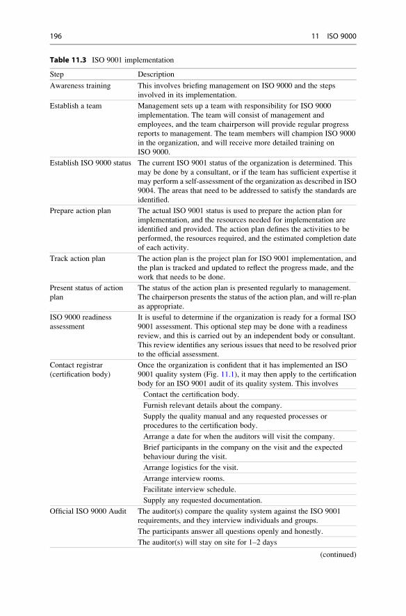
Table 11.3 ISO 9001 implementation
Step Description
Awareness training This involves briefing management on ISO 9000 and the steps
involved in its implementation.
Establish a team Management sets up a team with responsibility for ISO 9000
implementation. The team will consist of management and
employees, and the team chairperson will provide regular progress
reports to management. The team members will champion ISO 9000
in the organization, and will receive more detailed training on
ISO 9000.
Establish ISO 9000 status The current ISO 9001 status of the organization is determined. This
may be done by a consultant, or if the team has sufficient expertise it
may perform a self-assessment of the organization as described in ISO
9004. The areas that need to be addressed to satisfy the standards are
identified.
Prepare action plan The actual ISO 9001 status is used to prepare the action plan for
implementation, and the resources needed for implementation are
identified and provided. The action plan defines the activities to be
performed, the resources required, and the estimated completion date
of each activity.
Track action plan The action plan is the project plan for ISO 9001 implementation, and
the plan is tracked and updated to reflect the progress made, and the
work that needs to be done.
Present status of action
plan
The status of the action plan is presented regularly to management.
The chairperson presents the status of the action plan, and will re-plan
as appropriate.
ISO 9000 readiness
assessment
It is useful to determine if the organization is ready for a formal ISO
9001 assessment. This optional step may be done with a readiness
review, and this is carried out by an independent body or consultant.
This review identifies any serious issues that need to be resolved prior
to the official assessment.
Contact registrar
(certification body)
Once the organization is confident that it has implemented an ISO
9001 quality system (Fig. 11.1), it may then apply to the certification
body for an ISO 9001 audit of its quality system. This involves
Contact the certification body.
Furnish relevant details about the company.
Supply the quality manual and any requested processes or
procedures to the certification body.
Arrange a date for when the auditors will visit the company.
Brief participants in the company on the visit and the expected
behaviour during the visit.
Arrange logistics for the visit.
Arrange interview rooms.
Facilitate interview schedule.
Supply any requested documentation.
Official ISO 9000 Audit The auditor(s) compare the quality system against the ISO 9001
requirements, and they interview individuals and groups.
The participants answer all questions openly and honestly.
The auditor(s) will stay on site for 1–2 days
(continued)
196 11 ISO 9000

arranging the logistics; providing all required documentation and records to the
assessors; and acting on any feedback provided by the assessors.
11.6 Review Questions
1. What is ISO 9000?
2. Explain the differences between ISO 9000, ISO 9001 and ISO 9004.
3. What are the advantages of achieving ISO 9001 certification?
4. Describe the ISO 9001 clauses.
5. Describe the steps involved in implementing ISO 9001.
6. Describe the steps involved in applying for ISO 9001 certification.
7. Describe how ISO 9000 may be used for improvement.
Table 11.3 (continued)
Step Description
The standard requires certain processes and procedures, records, and
controls to be in place.
The auditors will examine evidence of compliance and records
The auditors will determine the extent to which the written procedures
correspond to the actual observed behaviour.
The auditors will publish an evaluation report which will detail the
findings of the audit.
The auditors may identify corrective actions to be carried out prior to
the granting of ISO 9001 certification.
The company is required to carry out the corrective actions, and these
are then verified.
The ISO 9001 registration is then granted.
The registration is valid for approximately 2 years, and follow-up
audits are conducted to ensure that the quality system remains ISO
9001 compliant.
Continuous improvement The organization will use the feedback from the formal assessment to
continuously improve.
Celebrate The award of ISO 9001 certification is a major achievement for the
organization and merits a celebration. The celebration demonstrates
the importance attached to quality and customer satisfaction
Table 11.4 Simple ISO 9000 self-assessment
ISO 9000 clause
Not
implemented
Partially
implemented
Largely
implemented
Fully
implemented
4.2.4 Control of records
5.3 Quality policy
5.6 Management review
6.2.2 Competence
7.2.3 Customer reqs
11.6 Review Questions 197

11.7 Summary
ISO 9000 is an international quality standard which enables an organization to
implement a sound quality system that is dedicated to customer satisfaction and
continuous improvement. The independent certification of ISO 9001 indicates
that the company has a sound quality management system in place, and that the
company is committed to the core values of quality, customer satisfaction, and
continuous improvement.
The ISO 9000 standards may be applied to various types of organizations,
including manufacturing, software, and service organizations. It is regarded as a
minimal quality standard that an organization committed to quality should satisfy.
Many organizations require their subcontractors to be ISO 9001 certified, as this
provides confidence in the subcontractor’s quality system, and in the ability of the
subcontractor to produce high-quality software.
The latest revision of ISO 9000 is termed ISO 9000:2008, and it places emphasis
on customer satisfaction and continuous improvement. It includes a process
model and the emphasis in the standard is on processes, and in improvement to
the processes. It is a family of standards and includes ISO 9000, ISO 9001, and ISO
9004. The ISO 9004 standard provides practical guidance on the implementation of
ISO 9001, and guidelines for performance improvement of the quality system.
The implementation of ISO 9001 involves setting up a team to manage the
implementation, and in providing the required resources for implementation.
A self-assessment may be performed to indicate the current ISO 9001 status, and
an action plan prepared to address the weaker areas. The implementation is
managed and tracked like a normal project, and it involves defining processes and
procedures, maintaining records, and training. The quality group in the organization
will play a key role in the implementation of the standard and in ensuring com-
pliance with the ISO 9001 requirements. The award of ISO 9001 certification
provides an indication that the company is focused on quality, customer satisfaction
and continuous improvement.
198 11 ISO 9000
Software Process Improvement 12
Key Topics
Software Process
Software Process Improvement
Process Mapping
Benefits of Software Process Improvement
CMMI
ISO/IEC 15504 (SPICE)
ISO 9000
PSP and TSP
Root Cause Analysis
Six Sigma
12.1 Introduction
The success of business today is highly influenced by the functionality and quality
of the software that it uses. It is essential that the software is safe, reliable, of a high
quality and fit for purpose. Companies may develop their own software internally,
or they may acquire software solutions off-the-shelf or from bespoke software
development. Software development companies need to deliver high-quality and
reliable software consistently on time to their customers.
Cost is a key driver in most organizations and it is essential that software is
produced as cheaply and efficiently as possible, and that waste is reduced or
eliminated in the software development process. In a nutshell, companies need to
produce software that is better, faster and cheaper than their competitors in order to
survive in the market place. That is, companies need to continuously work smarter
to improve their businesses and to deliver superior solutions to their customers.
G. O’Regan, Introduction to Software Quality, Undergraduate Topicsin Computer Science, DOI 10.1007/978-3-319-06106-1_12,# Springer International Publishing Switzerland 2014
199
Software process improvement initiatives are aligned to business goals and
play a key role in helping companies achieve their strategic goals. It is invaluable
in the implementation of best practice in organizations, and allows companies to
focus on fire prevention rather than firefighting. It allows companies to problem
solve key issues to eliminate quality problems, and to critically examine their
current processes to determine the extent to which they meets its needs, as well
as identifying how the processes can be improved, and where waste can be mini-
mized or eliminated.
It allows companies to identify the root causes of problems (e.g., using the fivewhy tool), and to determine appropriate solutions to the problems. The benefits of
successful process improvement include the consistent delivery of high-quality
software, improved financial results and increased customer satisfaction.
Software process improvement initiatives lead to a focus on the process and on
ways to improve it. Many problems are caused by defective processes rather than
people, and a focus on the process helps to avoid a blame culture that occurs
when blame is apportioned to individuals rather than the process. The focus on
the process leads to a culture of openness in discussing problems and their
solutions, and in instilling process ownership in the process practitioners.
Software process improvement allows companies to mature their software engi-
neering processes, and to achieve their business goals more effectively. It helps
software companies to deliver high-quality software on-time and on-budget, as
well, reducing the cost of development, and improving customer satisfaction. It has
become an indispensable tool for software engineers and managers to achieve their
goals, and provides a return on investment to the organization.
12.2 What Is a Software Process?
A software development process is the process used by software engineers to design
and develop computer software. It may be an undocumented ad hoc process as
devised by the team for a particular project, or it may be a standardized and
documented process used by various teams on similar projects. The process is
seen as the glue that ties people, technology and procedures coherently together.
The processes employed in software development include processes to deter-
mine the requirements; processes to design and development software; processes to
verify that the software is fit for purpose; and processes to maintain the software.
A software process is a set of activities, methods, practices and transformations
that people use to develop and maintain software and the associated work products.
DEFINITION 12.1 (SOFTWARE PROCESS) A process is a set of practices or tasks
performed to achieve a given purpose. It may include tools, methods, material
and people.
200 12 Software Process Improvement

An organization will typically have many processes in place for doing its work,
and the object of process improvement is to improve these to meet business goals
more effectively.
The Software Engineering Institute (SEI) believes that there is a close relation-
ship between the quality of the delivered software and the quality and maturity of
the underlying processes employed to create the software. The SEI adopted and
applied the principles of process improvement employed in the manufacturing field
to develop process maturity models such as the CMM and its successor the CMMI.
These maturity models are invaluable in maturing software processes in software
intensive organizations.
The process is an abstraction of the way in which work is done in the organi-
zation, and is seen as the glue that ties people, procedures and tools together
(Fig. 12.1).
A process is often represented by a process map which details the flow of activities
and tasks. The process map will typically include the inputs to each activity as well
as the output from an activity. Often, the output from one activity will become an
input to the next activity. A simple example of a process map for creating the system
requirements specification is described in Fig. 12.2. The input to the activity to create
the systems requirements specification will typically be the business requirements,
whereas the output is the systems requirements specification document itself.
As a process matures it is defined in more detail and documented. It will have
clearly defined entry and exit criteria, inputs and outputs, an explicit description
of the tasks, verification of the process and consistent implementation throughout
the organization.
Process
Procedures
People Technology
StandardsProceduresChecklists
Fig. 12.1 Process as glue for people, procedures and tools
12.2 What Is a Software Process? 201

12.3 What Is Software Process Improvement?
The origins of the software process improvement field go back to Walter Shewhart’s
work on statistical process control in the 1930s. Software process improvement is
concerned with practical action to improve the processes in the organization to ensure
that they meet business goals more effectively. For example, the goal may be to
deliver projects faster and with higher quality.
Shewhart’s work was later refined by Deming and Juran, and they argued
that high-quality processes are essential to the delivery of a high-quality product.
They argued that the quality of the end product is largely determined by the
processes used to produce and support it, and that therefore needs to be an emphasis
on the process as well as the product.
These quality gurus argued that product quality will improve as variability in
process performance is reduced [15], and their approach was effective in transfor-
ming manufacturing companies with quality problems to companies that could
consistently deliver high-quality products. Further, the improvements to quality
led to cost reductions and higher productivity, as less time was spent in reworking
defective products.
The work of Deming and Juran was later applied to the software quality field by
Watt Humphries and others at the SEI leading to the birth of the software process
improvement field.
DEFINITION 12.2 (SOFTWARE PROCESS IMPROVEMENT) A program of activities
designed to improve the performance and maturity of the organization’s software
processes and the results of such a program.
Software process improvement initiatives support the organization in achieving
its key business goals such as delivering software faster to the market, improving
quality, reducing or eliminating waste. The objective is to work smarter and to build
software better, faster, and cheaper than competitors. Software process improve-
ment makes business sense and provides a return on investment.
There are international standards and models available to support software
process improvement. These include the CMMI Model, the ISO 90001 standard,
and ISO 15504 (popularly known as SPICE). The CMMI model was developed by
Create SystemRequirements
BusinessRequirements
System RequirementsSpecification
Fig. 12.2 Sample process map
202 12 Software Process Improvement

the Software Engineering Institute (SEI), and includes best practice for processes in
software and systems engineering. The ISO 9001 standard is a quality management
system that may be employed in hardware or software development companies.
The ISO 15504 standard is an international standard for software process improve-
ment and process assessment.
Software process improvement is concerned with defining the right processes
and following them consistently. It involves training all staff on the new processes,
refining the processes, and continuously improving the processes.
12.4 What Are the Benefits of Software Process Improvement?
It is a challenge to deliver high-quality software consistently on time. There are
problems with budget and schedule overruns, late delivery of the software, spiral-
ling costs, quality problems with the delivered software, customer complaints, and
staff morale.
Software process improvement can assist in dealing with these problems.
There are costs involved but it provides a return on the investment made. Specifi-
cally, the benefits from software process improvement include:
– Improvements to quality
– Reductions in the cost of poor quality
– Improvements in productivity
– Reductions to the cost of software development
– Improvements in on-time delivery
– Improved consistency in budget and schedule delivery
– Improvements to customer satisfaction
– Improvements to employee morale
The Software Engineering Institute maintains data on the benefits that organi-
zations have achieved from using the CMMI. These include improvements in
several categories such as cost, schedule, productivity, quality, customer satisfac-
tion, and the return on investment.
Table 12.1 presents the results from 25 organizations. These results are from
conference presentations, published papers and individual collaborations [59].
For example, Northrop Grumman Defense Systems met every milestone (25 in a
row) with high-quality and customer satisfaction; Lockheed Martin reported an
80 % increase in software productivity over a 5 year period when it achieved CMM
level 5 and obtained further increases in productivity as it moved to CMMI level
5. Siemens (India) reported an improved defect removal rate from over 50 % before
testing to over 70 % before testing, and a post- release defect rate of 0.35 defects per
KLOC. Accenture reported a 5:1 return on investment from software process
improvement activities.
12.4 What Are the Benefits of Software Process Improvement? 203

12.5 What Models Are Used in Software Process Improvement?
A process model1 such as the CMMI defines best practice for software processes in
an organization. It describes what the processes should do rather than how they
should be done, and this allows the organization to use its professional judgment in
the implementation of processes to meet its needs. The process model will need to
be interpreted and tailored to the particular organization.
A process model provides a place to start an improvement initiative and it
provides a common language and shared vision for improvement. It provides a
framework to prioritize actions and allows the benefits of the experience of other
organizations to be shared. The popular process models used in software process
improvement include:
– Capability Maturity Model Integration (CMMI)
– ISO 9001 Standard
– ISO 15504
– PSP and TSP
– Six Sigma
– IEEE standards
– Root Cause Analysis (RCA)
– Balanced Scorecard
The CMMI was developed by the Software Engineering Institute, and is the
successor to the older software CMM which was released in the early 1990s.
The latter was specific to the software field it was influenced by Watt Humphrey’s
work at IBM [29]. The CMMI is a suite of products used for improving processes,
and it includes models, appraisal methods and training material. The CMMI
models address three areas of interest:
– CMMI for Development (CMMI-DEV)
– CMMI for Services (CMMI-SVC)
– CMMI for Acquisition (CMMI-ACQ)
The CMMI Development Model is discussed in the next chapter. It is a frame-
work that allows organizations to improve their maturity by improvements to their
Table 12.1 Benefits of software process improvement (CMMI)
Improvements Median (%) #Data points (%) Low (%) High (%)
Cost 20 21 3 87
Schedule 37 19 2 90
Productivity 62 17 9 255
Quality 50 20 7 132
Customer satisfaction 14 6 �4 55
ROI 4.7:1 16 2:1 27:1
1 There is the well-known adage “All models are wrong, some are useful”.
204 12 Software Process Improvement

underlying processes. It provides a structured approach and allows the organization
to set improvement goals and priorities. It provides a clearly defined roadmap for
improvement and it allows the organization to improve at its own pace. Its approach
is evolutionary rather than revolutionary, and it recognizes that a balance is required
between project needs and process improvement needs. It allows the processes to
evolve from ad hoc immature activities to disciplined mature processes.
The CMMI practices may be used for the development, acquisition and mainte-
nance of products and services. A SCAMPI appraisal determines the process maturity
of an organization and allows it to benchmark itself against other organizations.
ISO 9001 is an internationally recognized quality management standard and is
customer and process focused. It applies to the processes that an organization uses
to create and control products and services, and it emphasizes continuous improve-
ment.2 The standard is designed to apply to any product or service that an organi-
zation supplies.
The implementation of ISO 9001 involves understanding the requirements of
the standard and how the standard applies to the organization. It requires the
organization to identify its quality objectives, define a quality policy, produce
documented procedures, and carry out independent audits to ensure that the pro-
cesses and procedures are followed. An organization may be certified against the
ISO 9001 standard to gain recognition to its commitment to quality and continuous
improvement. The certification involves an independent assessment of the organi-
zation to verify that it has implemented the ISO 9001 requirements properly, and
that the quality management system is effective. It will also verify that the pro-
cesses and procedures defined are consistently followed and that appropriate
records are maintained. The ISO 9004 standard provides guidance for continuous
improvement.
The ISO/IEC 15504 standard (popularly known as ISO SPICE) is an interna-
tional standard for process assessment. It includes guidance for process improve-
ment and for process capability determination, as well as guidance for performing
an assessment. It includes an exemplar process model for software and systems
lifecycle processes. There is a version of SPICE termed “Automotive SPICE” that isused in the automotive sector.
ISO/IEC 15504 can be used in a similar way to the CMMI and its exemplar
models (for either software or systems lifecycles) may be employed to implement
best practice in process definition. Assessments may be performed to identify
strengths and opportunities for improvement.
The Personal Software Process (PSP) is a disciplined data driven software
development process that is designed to help software engineers understand and to
improve their personal software process performance. It was developed by Watt
Humphrey at the SEI, and it helps engineers to improve their estimation and planning
skills and to and to reduce the number of defects in their work. This enables them to
make commitments that they can keep and to manage the quality of their projects.
2 The ISO 9004 standard provides guidance on continuous improvement.
12.5 What Models Are Used in Software Process Improvement? 205

The Team Software Process (TSP) was developed by Watt Humphries at the
SEI, and is a structured approach designed to help software teams understand and
improve their quality and productivity. Its focus is on building an effective software
development team, and it involves establishing team goals, assigning team roles as
well as other teamwork activities. Team members must already be familiar with
the PSP.
Six Sigma (6σ) was developed by Motorola as a way to improve quality and
reduce waste. Its approach is to identify and remove the causes of defects in
processes by reducing process variability. It uses quality management techniques
and tools such as the five whys, business process mapping, statistical techniques,
and the DMAIC and DMADV methodologies. There are several roles involved in
six sigma initiatives such as Champions, Black Belts and Green Belts, and each role
requires knowledge and experience and is awarded on merit subject to training and
certification. Sponsorship and leadership is required from top management to
ensure the success of a Six Sigma initiative. Six Sigma was influenced by earlier
quality management techniques developed by Shewhart, Deming and Juran.
A Six Sigma project follows a defined sequence of steps and has quantified
targets. These targets may be financial, quality, customer satisfaction, and cycle
time reduction.
12.6 Process Mapping
The starting point for improving a process is first to understand the process as it is
currently performed. The process stakeholders reach a common understanding
of how the process is actually performed, and to identify how it may be improved.
The process as currently performed is then sketched pictorially, with the activities
and their inputs and outputs recorded graphically. This graphical representation is
termed a “process map” and is an abstract description of the process “as is”.The process map is an abstraction of the way that work is done, and it may be
critically examined to determine how effective it really is, and to identify weak-
nesses. This critical examination of the process by the process practitioners leads to
modifications to its definition, and the proposed definition is sketched in a new
process map to yield the process “to be”. Once the team has agreed the new process
the templates required to support the process become clear from an examination
of the input and output of the various activities. Procedures or guidelines will be
documented to provide the details on how the process is to be carried out.
12.7 Process Improvement Initiatives
The need for a software process improvement initiative often arises from the
realization that the organization is weak in some areas in software engineering,
and that it needs to improve to achieve its business goals more effectively.
206 12 Software Process Improvement

The starting point of any improvement initiative is an examination of the business
goals of the organization and these may include:
– Delivering high-quality products on time
– Delivering products faster to the market
– Reducing the cost of software development
– Improving software quality
There is more than one approach to the implementation of the CMMI. A small
organization has fewer resources available and team members involved in the
initiative will typically be working part time. Larger organizations may be able
to assign people full time on the improvement activities. The software process
improvement initiative should be designed to enable the organization achieve its
business goals more effectively.
Once the organization goals have been defined the improvement initiative
commences. This involves conducting an appraisal to determine the current strengths
and weaknesses of the processes; analysing the results to formulate a process impro-
vement plan; implementing the plan; piloting the improved processes and verifying
that they are effective; rolling out the new processes. The improvements are moni-
tored for effectiveness and the cycle repeats. The philosophy is:
• The improvement initiative is based on business needs
• Improvements should be planned based on an objective understanding of the
strengths and weaknesses of the current processes in the organization
• The CMMI Model or an alternate model is the vehicle for improvement.
• The improvements are prioritized (it is not possible to do everything at once).
• The improvement initiative needs to be planned and managed as a project.
• The results achieved need to be reviewed at the end of the period, and a new
improvement cycle started for continuous improvement
• Software process improvement requires people to change their behaviour, and so
organization culture needs to be considered.
• There needs to be a Process Champion to drive the process improvement
initiative in the organization.
• Senior management need to be 100 % committed to the success of the initiative.
• Staff need to be involved in the improvement initiative, and there needs to be a
balance between project needs and the improvement activities
The continuous improvement cycle is influenced by the IDEALSM model and by
Deming’s Plan-Do-Check-Act (PDCA) process improvement cycle. It is described
in Chap. 14.
12.8 Barriers to Success
Software process improvement initiatives are not always successful, and occasionally
an improvement initiative is abandoned. Some of the reasons for failure are:
– Unrealistic expectations
– Trying to do too much at once
– Lack of Senior Management Sponsorship
12.8 Barriers to Success 207

– Focusing on a Maturity Level
– Poor Project Management of the initiative
– Not run as a standard project
– Insufficient involvement of staff
– Insufficient time to work on improvements
– Inadequate training on Software Process Improvement
– Lack of pilots to validate new processes
– Inadequate rollout of new processes
It is essential that a software process improvement initiative is treated as a
standard project with a project manager assigned to manage the initiative. Senior
management need to be 100 % committed to the success of the initiative, and they
need to make staff available to work on the improvement activities. It needs to
be clear to all staff that the improvement initiative is a priority to the organization.
All employees need to receive appropriate training on software process improve-
ment and on the process maturity model.
The CMMI project manager needs to consider the risks of failure of the initiative
and to manage them accordingly.
12.9 Review Questions
1. What is a software process?
2. What is software process improvement?
3. What are the benefits of software process improvement?
4. Describe the various models available for software process improvement?
5. Draw the process map for the process of cooking your favourite meal.
6. Describe how a process improvement initiative may be run?
7. What are the main barriers to successful software process improvement
initiatives and how can they be overcome?
12.10 Summary
The success of business is highly influenced by software, and companies may
develop their own software internally, or they may acquire software solutions off-
the-shelf or from bespoke software development. Companies need to produce
software that is better, faster and cheaper than their competitors in order to survive
in the market place.
Software process improvement plays a key role in helping companies to achieve
their strategic goals, and is invaluable in the implementation of best practice in
organizations. It allows companies to focus on fire prevention rather than firefig-
hting, and to critically examine their processes to determine the extent to which
208 12 Software Process Improvement

they meet their needs. It enables them to identify how the process may be improved
and how waste can be minimized or eliminated.
Software process improvement initiatives lead to a focus on the process, and a
focus on process thinking is important since many problems are caused by defective
processes rather than by people. A focus on the process rather than people leads to a
culture of openness in discussing problems, and instils process ownership in the
process practitioners.
Software process improvement allows companies to mature their software engi-
neering processes, and to achieve their business goals more effectively. It helps
software companies to deliver the agreed software on-time and on-budget, as well
as improving the quality of the delivered software, reducing the cost of development,
and improving customer satisfaction. It has become an indispensable tool for soft-
ware engineers and managers to achieve their goals, and provides a return on
investment to the organization.
The next chapter gives an introduction to the Capability Maturity Model
Integration.
12.10 Summary 209

Capability Maturity Model Integration 13
Key Topics
CMMI Maturity Levels
CMMI Capability Levels
CMMI Staged Representation
CMMI Continuous Representation
CMMI Process Areas
Appraisals
13.1 Introduction
The Software Engineering Institute1 developed the Capability Maturity Model
(CMM) in the early 1990s as a framework to help software organizations improve
their software process maturity. The CMMI is the successor to the older CMM, and
its implementation brings best practice in software and systems engineering into the
organization. The SEI and many other quality experts believe that there is a close
relationship between the maturity of software processes and the quality of the
delivered software product.
1 The SEI was founded by the US Congress in 1984 and has worked successfully in advancing
software engineering practices in the US and worldwide. It performs research to find solutions to
key software engineering problems, and its proposed solutions are validated through pilots. These
solutions are then disseminated to the wider software engineering community through its training
programme. The SEI’s research and maturity models have played an important role in helping
companies to deliver high-quality software consistently on time and on budget. The SEI opened a
European office in Frankfurt, Germany in 2004.
G. O’Regan, Introduction to Software Quality, Undergraduate Topicsin Computer Science, DOI 10.1007/978-3-319-06106-1_13,# Springer International Publishing Switzerland 2014
211

The CMM built upon the work of quality gurus such as Deming [15], Juran [33]
and Crosby [14]. These quality gurus were effective in transforming struggling
manufacturing companies with quality problem to companies that could consis-
tently produce high quality products. Their success was due to the focus on
improving the manufacturing process and in reducing variability in the process.
The work of these quality experts was discussed in Chap. 1
Similarly, software companies need to have quality software processes to deliver
high-quality software to their customers. The SEI has collected empirical data to
suggest that there is a close relationship between software process maturity and the
quality of the delivered software. Therefore there is a need to focus on the software
process as well as on the product.
The CMM was released in 1991 and its successor, the CMMI® model, was
released in 2002 [13]. The CMMI is a framework to assist an organization in the
implementation of best practice in software and systems engineering. It is an
internationally recognized model for process improvement and is used world-
wide by thousands of organizations.
The focus of the CMMI is on improvements to the software process to ensure
that they meet business needs more effectively. A process is a set of practices or
tasks performed to achieve a given purpose. It may include tools, methods, material
and people. An organization will typically have many processes in place for doing
its work, and the object of process improvement is to improve these to meet
business goals more effectively.
The process is an abstraction of the way in which work is done in the organiza-
tion, and is seen as the glue (Fig. 13.1) that ties people, procedures and tools
together.
It may be described by a process map which details the flow of activities and
tasks. The process map will include the input to each activity and the output from
each activity. Often, the output from one activity will become the input to the next
activity. A simple example of a process map for creating the system requirements
specification was described in the previous chapter (Fig. 12.2).
The ISO/IEC 12207 standard for software processes distinguishes between
several categories of software processes including the primary life cycle processes
for developing and maintaining software; supporting processes to support the
software development lifecycle; and organization life cycle processes. These are
summarized in Fig. 13.2.
Watt Humphries began applying the ideas of Deming, Juran and Crosby to
software development, and he published the book “Managing the Software
Fig. 13.1 Process as glue for
people, procedures and tools
212 13 Capability Maturity Model Integration

Process” [29] after he moved to the SEI to work on software process maturity
models with the other SEI experts. The SEI released the Capability Maturity Model
in the early 1990s, and this process model has proved to be effective in assisting
companies in improving their software engineering practices and in achieving
consistent results and high-quality software.
The CMM is a process model and it defines the characteristics or best practices
of good processes. It does not prescribe how the processes should be done and
allows the organization the freedom to interpret the model to suit its particular
context and business needs. It also provides a roadmap for an organization to get
from where it is today to a higher level of maturity. The advantage of model-based
improvement is that it provides a place to start process improvement, as well as a
common language and a shared vision.
The CMM consists of five maturity levels with the higher maturity levels
representing advanced software engineering capability. The lowest maturity level
is level 1 and the highest is level 5. The SEI developed an assessment methodology
(CBA IPI) to determine the maturity of software organizations, and initially most
organizations were assessed at level 1 maturity. However, over time companies
embarked on improvement initiatives, and matured their software processes, and
today many companies are performing at the higher maturity levels.
Fig. 13.2 ISO/IEC 12207 standard for software engineering processes
13.1 Introduction 213
The first company to be assessed at CMM level 52 was the Motorola plant in
Bangalore in India. The success of the software CMM led to the development of
other process maturity models such as the systems engineering capability maturity
mode (CMM/SE) which is concerned with maturing systems engineering practices,
and the people capability maturity model (P-CMM) which is concerned with
improving the ability of the software organizations to attract, develop, and retain
talented software engineering professionals.
The SEI commenced work on the CMMI® [13] in the late 1990s. This is a
replacement for the older CMM model and its development included merging the
software CMM and systems CMM, and ensuring that the new model was compati-
ble with the ISO 15504 standard.3 It is described in the next Section.
13.2 The CMMI
The CMMI consists of five maturity levels with each maturity level (except level 1)
consisting of a number of process areas. Each process area consists of a set of goals,
and these must be implemented by a set of related practices in order for the process
area to be satisfied. The practices specify what is to be done rather than how it
should be done. Processes are activities associated with carrying out certain tasks,
and they need to be defined and documented. The users of the process need to
receive appropriate training to enable them to carry out the process, and process
discipline need to be enforced by independent audits. Process performance needs to
be monitored and improvements made to ineffective processes.
The emphasis for level 2 of the CMMI is on maturing management practices
such as project management, requirements management, configuration manage-
ment, and so on. The emphasis on level 3 of the CMMI is on maturing engineering
and organization practices. Maturity level 3 is concerned with defining standard
organization processes, and it also includes process areas for the various engineer-
ing activities needed to design and develop the software. Level 4 is concerned with
ensuring that key processes are performing within strict quantitative limits, and
adjusting processes, where necessary, to perform within these limits. Level 5 is
concerned with continuous process improvement. Maturity levels may not be
skipped in the staged implementation of the CMMI, as each maturity level is the
foundation for work on the next level.
2 Of course, the fact that a company has been appraised at a certain CMM or CMMI rating is no
guarantee that it is performing effectively as a commercial organization. For example, the
Motorola plant in India was appraised at CMM level 5 in the late 1990s while Motorola lost
business opportunities in the GSM market.3 ISO 15504 (popularly known as SPICE) is an international standard for software process
assessment.
214 13 Capability Maturity Model Integration

There is also a continuous representation4 of the CMMI that allows the organi-
zation to focus its improvements on key processes that are closely related to its
business goals. This allows it the freedom to choose an approach that should result
in the greatest business benefit rather than proceeding on the standard improvement
roadmap. However, in practice it is often necessary to implement several of the
level 2 process areas before serious work can be done on maturing a process to a
higher capability level. Table 13.1 presents the motivation for the implementation
of the CMMI.
The CMMI model covers both the software engineering and systems engineering
disciplines. Systems engineering is concerned with the development of systems that
may or may not include software, whereas software engineering is concerned with
the development of software systems. The model contains extra information rele-
vant to a particular discipline, and this is done by discipline amplification.5
Table 13.1 Motivation for CMMI implementation
Motivation for CMMI implementation
Enhances the credibility of the company
Marketing benefit of CMMI maturity level
Implementation of best practice in software and systems engineering
Logical path to improvement
It increases the capability and maturity of an organization
It improves the management of subcontractors
It provides improved technical and management practices
It leads to higher quality of software
It leads to increased timeliness of projects
It reduces the cost of maintenance and incidence of defects
It allows the measurement of processes and products
It allows projects/products to be quantitatively managed
It allows innovative technologies to be rigorously evaluated to enhance process performance
It improves customer satisfaction
It changes the culture from firefighting to fire prevention
It leads to a culture of improvement
It leads to higher morale in company
4Our focus is on the implementation of the staged representation of the CMMI rather than the
continuous representation. This is my preferred approach to process improvement as it provides a
clearly defined roadmap, and also allows benchmarking of organizations. Appraisals against the
staged representation are useful since a CMMI maturity level rating is awarded to the organization,
and the company may use this to publicise its software engineering capability.5 Discipline amplification is a specialised piece of information that is relevant to a particular
discipline. It is introduced in the model by text such as “For Systems Engineering”
13.2 The CMMI 215

The CMMI allows organizations to benchmark themselves against similar
organizations. This is generally done by a formal SEI SCAMPI Class A appraisal6
conducted by an authorized SCAMPI lead appraiser (Fig. 13.3). The results will
generally be reported back to the SEI, and there is a strict qualification process to
become an authorised lead appraiser. The qualification process helps to ensure that
the appraisals are conducted fairly and objectively and that the results are consis-
tent. An appraisal is verifies that an organization has improved, and it enables the
organization to prioritize improvements for the next improvement cycle. Small
organizations will often prefer a SCAMPI Class B or C appraisal as these are less
expensive and time consuming.7
The time required to implement the CMMI in an organization depends on its size
and current maturity. It generally takes 1–2 years to implement maturity level 2, and
a further one to two years to implement level 3. The implementation of the CMMI
Fig. 13.3 CMMI Worldwide maturity 2013
6A SCAMPI appraisal is a systematic examination of the processes in an organization to
determine the maturity of the organization with respect to the CMMI. An appraisal team consists
of a SCAMPI lead appraiser, one or more external appraisers, and usually one internal appraiser. It
consists of interviews with senior and middle management and reviews with project managers and
project teams. The appraisers will review documentation and determine the extent to which the
processes defined are effective as well as the extent to which they are institutionalized in the
organization. Data will be gathered and reviewed by the appraisers, ratings produced and the
findings presented to the organization.7 Small organizations may not have the budget for a formal SCAMPI Class A appraisal. They may
be more interested in an independent SCAMPI Class B or C appraisal, which is used to provide
feedback on their strengths and opportunities for improvement. Feedback allows the organization
to focus its improvement efforts for the next improvement cycle.
216 13 Capability Maturity Model Integration
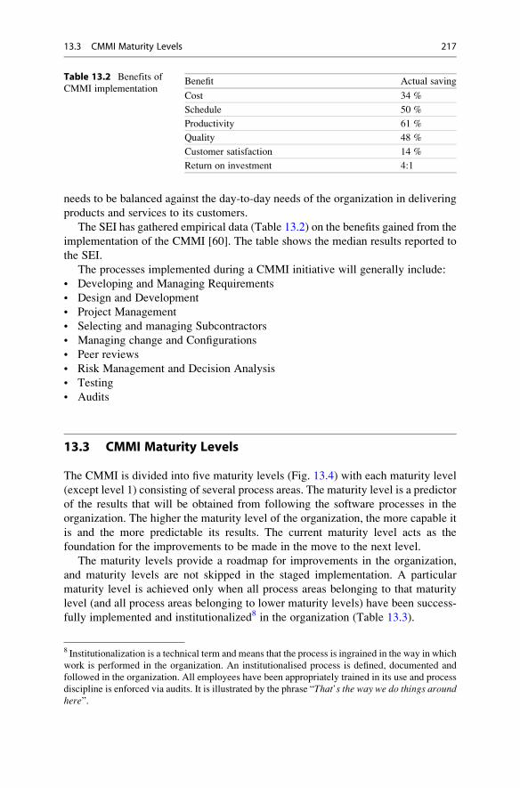
needs to be balanced against the day-to-day needs of the organization in delivering
products and services to its customers.
The SEI has gathered empirical data (Table 13.2) on the benefits gained from the
implementation of the CMMI [60]. The table shows the median results reported to
the SEI.
The processes implemented during a CMMI initiative will generally include:
• Developing and Managing Requirements
• Design and Development
• Project Management
• Selecting and managing Subcontractors
• Managing change and Configurations
• Peer reviews
• Risk Management and Decision Analysis
• Testing
• Audits
13.3 CMMI Maturity Levels
The CMMI is divided into five maturity levels (Fig. 13.4) with each maturity level
(except level 1) consisting of several process areas. The maturity level is a predictor
of the results that will be obtained from following the software processes in the
organization. The higher the maturity level of the organization, the more capable it
is and the more predictable its results. The current maturity level acts as the
foundation for the improvements to be made in the move to the next level.
The maturity levels provide a roadmap for improvements in the organization,
and maturity levels are not skipped in the staged implementation. A particular
maturity level is achieved only when all process areas belonging to that maturity
level (and all process areas belonging to lower maturity levels) have been success-
fully implemented and institutionalized8 in the organization (Table 13.3).
Table 13.2 Benefits of
CMMI implementationBenefit Actual saving
Cost 34 %
Schedule 50 %
Productivity 61 %
Quality 48 %
Customer satisfaction 14 %
Return on investment 4:1
8 Institutionalization is a technical term and means that the process is ingrained in the way in which
work is performed in the organization. An institutionalised process is defined, documented and
followed in the organization. All employees have been appropriately trained in its use and process
discipline is enforced via audits. It is illustrated by the phrase “That’s the way we do things aroundhere”.
13.3 CMMI Maturity Levels 217

The implementation of the CMMI generally starts with improvements to pro-
cesses at the project level. The focus at level 2 is on improvements to managing
projects and suppliers, and improving project management, supplier selection and
management practices, and so on.
The improvements at level 3 involve a shift from the focus on projects to the
organization. It involves defining standard processes for the organization, and
projects may then tailor the standard process (using tailoring guidelines) to produce
the project’s software process. Projects are not required to do everything in the
same way as the tailoring of the process allows the project’s defined software
process to reflect the unique characteristics of the project: i.e., a degree of variation
is allowed as per the tailoring guidelines.
The implementation of level 3 requires defining procedures and standards for
engineering activities such as design, coding and testing. Procedures are defined for
peer reviews, testing, risk management and decision analysis.
Managed (L2)Requirements ManagementProject PlanningProject Monitoring and ControlSupplier Agreement ManagementMeasurement and AnalysisProcess and Product Quality AssuranceConfiguration Management
Defined (L3)Requirements DevelopmentTechnical SolutionProduct IntegrationVerificationValidationOrganisation Process FocusOrganisation Process DefinitionOrganisation TrainingIntegrated Project ManagementRisk ManagementDecision Analysis and Resolution
Quantitatively Managed (L4)Organisation Process PerformanceQuantitative Project Management
Optimising (L5)Organisation Innovation and DeploymentCausal Analysis and Resolution
Initial (L1)
Fig. 13.4 CMMI maturity levels
218 13 Capability Maturity Model Integration

Table 13.3 CMMI maturity levels
Maturity level Description
Initial Processes are often ad hoc or chaotic with performance often unpredictable.
Success is often due to the heroics of people rather than having high-quality
processes in place. The defined process is often abandoned in times of crisis,
and there are no audits to enforce the process.
It is difficult to repeat previous success, since success is due to heroic efforts
of its people rather than processes. These organizations often over-commit,
as they often lack an appropriate estimation process on which to base project
commitments.
Firefighting is a way of life in these organizations. High-quality software
might be produced but at a cost including long hours, high level of rework,
over budget and schedule and unhappy customers. Projects do not perform
consistently as their success is dependent on the people involved.
They may have few processes defined and poor change control, poor
estimation and project planning, and weak enforcement of standards.
Managed A level 2 organization has good project management practices in place, and
planning and managing new projects is based on experience with similar
previous projects.
The process is planned, performed and controlled. A level 2 organization is
disciplined in following processes, and the process is enforced with
independent audits.
The status of the work products produced by the process is visible to
management at major milestones, and changes to work products are
controlled. The work products are placed under appropriate configuration
management control.
The requirements for a project are managed and changes to the requirements
are controlled. Project management practices are in place to manage the
project, and a set of measures are defined for budget, schedule and effort
variance. Subcontractors are managed.
Independent audits are conducted to enforce the process. The processes in a
level 2 organization are defined at the project level.
Defined A maturity level 3 organization has standard processes defined that support
the whole organization.
These standard processes ensure consistency in the way that projects are
conducted across the organization. There are guidelines defined that allow
the organization process to be tailored and applied to each project.
There are standards in place for design and development and procedures
defined for effective risk management and decision analysis.
Level 3 processes are generally defined more rigorously than level
2 processes, and the definition includes the purpose of the process, inputs,
entry criteria, activities, roles, measures, verification steps, exit criteria and
output. There is also an organization wide training program.
QuantitativelyManaged
A level 4 organization sets quantitative goals for the performance of key
processes, and these processes are controlled using statistical techniques.
Processes are stable and perform within narrowly defined limits. Software
process and product quality goals are set and managed.
A level 4 organization has predictable process performance, with variation in
process performance identified and the causes of variation corrected.
(continued)
13.3 CMMI Maturity Levels 219

The implementation of level 4 involves achieving process performance within
defined quantitative limits. This involves the use of metrics and setting quantitative
goals for project and process performance, and managing process performance. The
implementation of level 5 is concerned with achieving a culture of continuous
improvement in the company. The causes of defects are identified and resolution
actions implemented to prevent a reoccurrence.
13.3.1 CMMI Representations
The CMMI is available in the staged and continuous representations. Both
representations use the same process areas as well as the same specific and generic
goals and practices.
The staged representation was described in Fig. 13.4 and is the approach
followed here. It follows the well-known improvement roadmap from maturity
level 1 through improvement cycles until the organization has achieved its desired
level of maturity. The staged approach is concerned with organization maturity and
allows statements of organization maturity to be made, whereas the continuous
representation is concerned with individual process capability.
The continuous representation is illustrated in Fig. 13.5, and it has been
influenced by the ISO 15504 standard for process assessment. It is concerned
with improving the capability of those selected processes, and gives the organiza-
tion the freedom to choose the order of improvements that best meet their business
needs. The continuous representation allows statements of individual process
capability to be made. It employs six capability levels and a process is rated at a
particular capability level.
Each capability level consists of a set of specific and generic goals and practices,
and the capability levels provide a path for process improvement within the process
area. Process improvement is achieved by the evolution of a process from its current
capability level to a higher capability level. For example, a company may wish to
mature its project planning process from its current process rating of capability
level 2 to a rating of capability level 3. This requires the implementation of
practices to define a standard project planning process as well as collecting
improvement data. The capability levels are listed in Table 13.4.
Table 13.3 (continued)
Maturity level Description
Optimizing A level 5 organization has a continuous process improvement culture in
place, and processes are improved based on a quantitative understanding of
variation.
Defect prevention activities are an integral part of the development lifecycle.
New technologies are evaluated and introduced (where appropriate) into the
organization. Processes may be improved incrementally or through
innovative process and technology improvements.
220 13 Capability Maturity Model Integration

An incomplete process is a process that is either partially performed or not
performed at all. A performed process carries out the expected practices and work
products. However, such a process may not be adequately planned or enforced. A
managed process is planned and executed with appropriately skilled and trained
Fig. 13.5 CMMI capability levels
Table 13.4 CMMI capability levels for continuous representation
Capability level Description
Incomplete (0) The process does not implement all of the capability level 1 generic and
specific practices. The process is either not performed or partially
performed.
Performed (1) A process that performs all of the specific practices and satisfies its specific
goals. Performance may not be stable.
Managed (2) A process at this level has infrastructure to support the process. It is
managed: i.e., planned and executed in accordance with policy, its users are
trained; it is monitored and controlled and audited for adherence to its
process description.
Defined (3) A process at this level has a defined process: i.e., a managed process that is
tailored from the organization’s set of standard processes. It contributes
work products, measures and other process improvement information to the
organization’s process assets.
Quantitatively
managed (4)
A process at this level is a quantitatively managed process: i.e., a defined
process that is controlled by statistical techniques. Quantitative objectives
for quality and process performance are established and used to control the
process.
Optimizing (5) A process at this level is an optimizing process: i.e., a quantitatively
managed process that is continually improved through incremental and
innovative improvements.
13.3 CMMI Maturity Levels 221

personnel. The process is monitored and controlled and periodically enforced via
audits.
A defined process is a managed process that is tailored from the standard process
in the organization using tailoring guidelines. A quantitatively managed process is a
defined process that is controlled using quantitative techniques. An optimizing
process is a quantitatively managed process that is continuously improved through
incremental and innovative improvements.
The process is rated at a particular capability level provided it satisfies all of the
specific and generic goals of that capability level, and it also satisfies the specific
and generic goals of all lower capability levels (Fig. 13.6).
We shall be concerned with the implementation of the staged representation of
the CMMI rather than the continuous representation. The reader is referred to [13]
for more information on both representations.
13.4 Categories of CMMI Processes
The process areas on the CMMI can be divided into four categories, as given in
Table 13.5.
13.5 CMMI Process Areas
This section provides an overview of the process areas of the CMMI model. All
maturity levels with the exception of level 1 contain several process areas. The
process areas are described in more detail in [13] (Table 13.6).
Fig. 13.6 CMMI – Continuous representation
222 13 Capability Maturity Model Integration

13.6 Components of CMMI Process Areas
The maturity level of an organization indicates the expected results that its projects
will achieve, and is a predictor of future project performance. Each maturity level
consists of a number of process areas, and each process area consists of specific and
generic goals, and specific and generic practices. Each maturity level is the foun-
dation for improvements for the next level.
The specific goals and practices are listed first and then followed by the generic
goals and practices. The specific goals and practices are unique to the process area
Table 13.5 CMMI process categories
Maturity level Description
Process
management
The process areas in this category are concerned with activities to define, plan,
implement, deploy, monitor, control, appraise, measure and improve the
processes in the organization: They include:
Organization Process Focus
Organization Process Definition
Organization Training
Organization Process Performance
Organization Innovation and Deployment
Project
management
These process areas are concerned with activities to create and maintain a
project plan, tailoring the standard process to produce the project’s defined
process, monitoring progress with respect to the plan, taking corrective action,
the selection and management of suppliers, and the management of risk. They
include:
Project Planning
Project Monitoring and Control
Risk Management
Integrated Project Management
Supplier Agreement Management
Quantitative Project Management
Engineering These process areas are concerned with engineering activities such as
determining and managing requirements, designing and development the
software, testing and maintenance of the product. They include:
Requirements Development
Requirements Management
Technical Solution
Product Integration
Verification
Validation
Support These process areas include activities that support product development and
maintenance. They include:
Configuration Management
Process and Product Quality Assurance
Measurement and Analysis
Decision Analysis and Resolution
13.6 Components of CMMI Process Areas 223

Table 13.6 CMMI process areas
Maturity
level
Process
area Description of process area
Level 2 REQM Requirements Management
This process area is concerned with managing the requirements for the
project and ensuring that the requirements, project plan(s) and work
products are kept consistent with the requirements.
PP Project Planning
This process area is concerned with estimation for the project, developing
and obtaining commitment to the project plan and maintaining the plan.
PMC Project Monitoring and Control
This process area is concerned with monitoring progress with the project
and taking corrective action when project performance deviates from
the plan.
SAM Supplier Agreement Management
This process area is concerned with the selection of suppliers,
documenting the (legal) agreement/statement of work with the supplier
and managing the supplier during the execution of the agreement.
MA Measurement and Analysis
This process area is concerned with determining management information
needs and measurement objectives. Measures are then specified to meet
these objectives, and data collection and analysis procedures are defined.
Data is collected and measurements analyzed and communicated.
PPQA Process and Product Quality Assurance
This process area is concerned with providing objective visibility to
management on the extent of process compliance. Non-compliance issues
are documented and resolved by the project team.
CM Configuration Management
This process area is concerned with the management of change. It involves
setting up a configuration management system; identifying the items that
will be subject to change control and controlling changes to them.
Configuration audits are conducted.
Level 3 RD Requirements Development
This process area is concerned with eliciting and defining customer,
product and product-component requirements and analyzing and
validating the requirements.
TS Technical Solution
This process area is concerned with the design, development and
implementation of an appropriate solution to the customer requirements.
PI Product Integration
This process area is concerned with the assembly of the product
components to deliver the product, and verifying that the assembled
components function correctly together.
VER Verification
This process area is concerned with ensuring that selected work products
satisfy their specified requirements. This is achieved by peer reviews and
testing.
(continued)
224 13 Capability Maturity Model Integration

being implemented, and are concerned with what needs to be done to perform the
process. The specific practices are linked to a particular specific goal, and they
describe activities that when performed achieve the associated specific goal for the
process area (Fig. 13.7).
Table 13.6 (continued)
Maturity
level
Process
area Description of process area
VAL Validation
This process area is concerned with demonstrating that the product or
product component is fit for purpose and satisfies its intended use.
OPF Organization Process Focus
This process area is concerned with planning and implementing process
improvements based on a clear understanding of the current strengths and
weakness of the organization’s processes.
OPD Organization Process Definition
This process area is concerned with creating and maintaining a usable set
of organization processes. This allows consistent process performance
across the organization.
OT Organization Training
This process area is concerned with developing the skills and knowledge
of people to enable them to perform their roles effectively.
IPM Integrated Project Management
This process area is concerned with tailoring the organization set of
standard processes to define the project’s defined process. The project is
managed according to the project’s defined process.
RSKM Risk Management
This process area is concerned with identifying risks and determining their
probability of occurrence and impact should they occur. Risks are
identified and managed throughout the project.
DAR Decision Analysis and Resolution
This process area is concerned with formal decision making. It involves
identifying options, specifying evaluation criteria and method, performing
the evaluation, and recommending a solution.
Level 4 OPP Organization Process Performance
This process area is concerned with obtaining a quantitative understanding
of the performance of selected organization processes in order to
quantitatively manage projects in the organization.
QPM Quantitative Project Management
This process area is concerned with quantitatively managing the project’s
defined process to achieve the project’s quality and performance
objectives.
Level 5 OID Organization Innovation and Deployment
This process area is concerned with incremental and innovative process
improvements.
QPM Causal Analysis and Resolution
This process area is concerned with identifying causes of defects and
taking corrective action to prevent a re-occurrence in the future.
13.6 Components of CMMI Process Areas 225

The generic goals and practices are common to all process areas for that maturity
level, and are concerned with process institutionalization at that level. Four com-
mon features organize the generic practices and these are:
• Commitment to perform
• Ability to perform
• Directing implementation
• Verifying implementation
They describe activities that when implemented achieve the associated generic
goal(s) for the process area. The commitment to perform practices relate to the
creation of policies and sponsorship of process improvement; the ability to perform
practices are related to the provision of appropriate resources and training to
perform the process; the directing implementation practices relate to activities to
control and manage the process; and verifying practices relate to activities to verify
adherence to the process.
The implementation of the generic practices institutionalizes the process and
makes it ingrained in the way that work is done. Institutionalization means that the
process is defined, documented and understood. Process users are appropriately
trained and the process is enforced by independent audits. Institutionalization helps
to ensure that the process is performed consistently and is more likely to be retained
during times of stress. The degree of institutionalization is reflected in the extent to
which the generic goals and practices are satisfied. The generic practices ensure the
sustainability of the specific practices over time.
There is one specific goal associated with the Requirements Management pro-
cess area and it has five associated specific practices (Fig. 13.8):
Fig. 13.7 CMMI staged model
226 13 Capability Maturity Model Integration

13.6.1 SG 1 – Manage Requirements
Requirements are managed and inconsistencies with project plans and workproducts are identified.
The components of the CMMI model are grouped into three categories: namely,
required, expected, and informative components. The required category is essentialto achieving goals in a particular area and includes the specific and generic goalsthat must be implemented and institutionalized for the process area to be satisfied.
The expected category includes the specific and generic practices that an organiza-tion will typically implement to perform the process effectively. These are intended
to guide individuals or groups who are implementing improvements, or who are
performing appraisals to determine the current maturity of the organization. They
state what needs to be done rather than how it should be done thereby giving
freedom on the most appropriate implementation for the organization.
The informative category includes information to guide the implementer on how
best to approach the implementation of the specific and generic goals and practices.
These include sub-practices, typical work products, discipline amplifications, andso on. This information assists with the implementation of the process area.
The implementation and institutionalization of a process area involves the
implementation of the specific and generic practices. The specific practices are
concerned with process implementation and are described in detail in [49]. The
generic practices are concerned with process institutionalization and are
summarized in Table 13.7.
The generic goals support an evolution of process maturity, and the implemen-
tation of each generic goal provides a foundation for further process improvements.
That is, a process rated at a particular maturity level has all of the maturity of a
process at the lower levels and the additional maturity of its rated level. In other
words, a defined process is a managed process; a quantitatively managed process is
a defined process, and so on.
Fig. 13.8 Specific practices for SG1 – manage requirements
13.6 Components of CMMI Process Areas 227

Table 13.7 CMMI generic practices
Generic goal
Generic
practice Description of generic practice
GG 1 GP 1.1 Perform Base Practices
Performed Process The purpose of this generic practice is to produce the work
products and services associated with the process (i.e., as
specified in the specific practices). These practices may be
done informally without following a documented process
description and success is dependent on the individuals
performing the work. That is, the basic process is performed
but it may be immature.
GG 2 GP 2.1 Organization Policy
Managed Process The organization policy is established by senior management,
and defines the management expectations of the organization.
GP 2.2 Plan the Process
This generic practice is concerned with preparing a plan to
perform the process. The plan will assign responsibilities and
document the resources needed to perform the process as well
as any training requirements. The plan/schedule are revised as
appropriate.
GP 2.3 Provide Resources
The purpose of this generic practice is to ensure that the
resources required to perform the process (as specified in the
plan) are available when required.
GP 2.4 Assign Responsibility
The purpose of this generic practice is to assign responsibility
for performing the process and developing the work products.
GP 2.5 Train People
This generic practice is concerned with ensuring that people
receive the appropriate training to enable them to perform and
support the process.
GP 2.6 Manage Configurations
This generic practice is concerned with identifying the work
products created by the process that will be subject to
configuration management control. These are documented in
the plan for the process.
GP 2.7 Identify and Involve Relevant Stakeholders
This is concerned with ensuring that the stakeholders are
identified (as described in the plan for the process) and
involved appropriately during the execution of the process.
GP 2.8 Monitor and Control the Process
This generic practice is concerned with monitoring process
performance and taking corrective action when necessary.
GP 2.9 Objectively Evaluate Adherence
This generic practice is concerned with conducting audits to
verify that process execution adheres to the process
description.
GP 2.10 Review Status with Higher Level Management
This generic practice is concerned with providing higher level
management with appropriate visibility into the process.
(continued)
228 13 Capability Maturity Model Integration

Several of the CMMI process areas support the implementation of the generic
goals and practices. These process areas contain one or more specific practices that
when implemented may either fully implement a generic practice, or generate a
work product that is used in the implementation of the generic practice. The
implementation of the generic practices is supported by the process areas men-
tioned in Table 13.8.
13.7 SCAMPI Appraisals
An appraisal is conducted to enable an organization to understand its current
software process maturity, and to prioritize future improvements. The appraisal is
an independent examination of the processes used in the organization against the
CMMI standard. Its objective is to identify strengths and weaknesses in the
processes, and it is used to prioritize improvements in the next improvement cycle.
The SCAMPI methodology is the appraisal methodology used with the CMMI,
and it comes in three distinct flavours (SCAMPI Class A, B, and C). These classes
Table 13.7 (continued)
Generic goal
Generic
practice Description of generic practice
GG 3 GP 3.1 Establish a Defined Process
Defined Process This generic practice is concerned with tailoring the
organization set of standard processes to produce the project’s
defined process.
GP 3.2 Collect Improvement Information
This generic practice is concerned with collecting
improvement information and work products to support future
improvement of the processes.
GG 4 GP 4.1 Establish Quantitative Objectives
Quantitatively
Managed Process
This is concerned with agreeing quantitative objectives (e.g.,
quality/performance) for the process with the stakeholders.
GP 4.2 Stabilize Sub-process Performance
This generic practice is concerned with stabilizing the
performance of one or more key sub-processes of the process
using statistical techniques. This enables the process to achieve
its objectives.
GG 5 GP 5.1 Ensure Continuous Process Improvement
Optimizing Process This generic practice is concerned with systematically
improving selected processes to meet quality and process-
performance targets.
GP 5.2 Correct Root Cause of Problems
This generic practice is concerned with analyzing defects
encountered to correct the root cause of these problems and to
prevent re-occurrence.
13.7 SCAMPI Appraisals 229

vary in formality, the cost, effort and timescales involved, the rating of the
processes, and the reporting of results.
The scope of the appraisal includes the process areas to be examined, and the
projects and organization unit to be examined. It may be limited to the level
2 process areas, or the level 2 and level 3 process areas, and so on. The scope
depends on how active the organization has been in process improvement.
The appraisal will identify any gaps that exist with respect to the implementation
of the CMMI practices for each process area within the scope of the appraisal. The
appraisal team will conduct interviews and review project documentation, and they
will examine the extent to which the practices are implemented. The appraisal
findings are presented and are used to plan and prioritize the next improvement
cycle. Chapter 15 discusses SCAMPI appraisals in more detail.
Table 13.8 Implementation of generic practices
Generic goal Generic practice
Process area supporting implementation
of generic practice
GG 2 GP 2.2 Project Planning
Managed Process Plan the Process
GP 2.5 Organization Training
Train the people Project Planning
GP 2.6 Configuration Management
Manage Configurations
GP 2.7 Project Planning
Identify/involve relevant
stakeholders
GP 2.8 Project Monitoring and Control
Monitor and Control the
process
GP 2.9 Process and Product Quality Assurance
Objectively evaluate
adherence
GG 3 GP 3.1 Integrated Project Management
Defined Process Establish defined process Organization Process Definition
GP 3.2 Integrated Project Management
Improvement Information Organization Process Focus
Organization Process Definition
GG 4 GP4.1 Quantitative Project Management
Quantitatively
Managed Process
Establish quantitative
objectives for process
Organization Process Performance
GP 4.2 Quantitative Project Management
Stabilize sub-process
performance
Organization Process Performance
GG 5 GP5.1 Organization Innovation and
DeploymentOptimizing Process Ensure Continuous Process
Improvement
GP 5.2 Causal Analysis and Resolution
Correct root cause of problems
230 13 Capability Maturity Model Integration

13.8 Review Questions
1. Describe the CMMI Model.
2. Describe the staged and continuous representations of the CMMI. What
are the advantages and disadvantages of each representation?
3. Describe the CMMI maturity levels and the process areas in each level.
4. What is the purpose of the CMMI generic practices? How are they
implemented?
5. What is the difference between implementation and institutionalization?
6. What is the purpose of CMMI appraisals and how do they fit into the
software process improvement cycle?
13.9 Summary
The Capability Maturity Model Integration is a framework to assist an organization
in the implementation of best practice in software and systems engineering. It was
developed at the Software Engineering Institute and is used by many organizations
around the world.
The SEI and other quality experts believe that there is a close relationship
between the quality of the delivered software, and the maturity of the processes
used to create the software. Therefore, there needs to be a focus on the process as
well as on the product, and the CMMI contains best practice in software and
systems engineering to assist in the creation of high-quality processes.
The process is seen as the glue that ties people, technology and procedures
coherently together. Processes are activities associated with carrying out certain
tasks, and they need to be defined and documented. The users of the process need to
receive appropriate training on their use, and process discipline need to be enforced
with independent audits. Process performance needs to be monitored and
improvements made to ineffective processes.
The CMMI consists of five maturity levels with each maturity level (except level
one) consisting of several process areas. Each maturity level acts as a foundation for
improvement for the next improvement level, and each increase in maturity level
represents more advanced software engineering capability. The higher the maturity
level of the organization, the more capable it is, and the more predictable its results.
The lowest level ofmaturity ismaturity level 1 and the highest level ismaturity level 5.
Each process area consists of a set of specific and generic goals, and these must
be implemented by an associated set of specific and generic practices. The practices
specify what is to be done rather than how it should be done, and the organization is
given freedom in choosing the most appropriate implementation to meet its needs.
The SCAMPI appraisal methodology is used to determine the maturity of
software organizations. It is a systematic examination of the processes used in the
organization against the CMMI model, and it includes interviews and reviews of
13.9 Summary 231
documentation. A successful SCAMPI Class A appraisal allows the organization to
report its maturity rating to the SEI and to benchmark itself against other
companies. Appraisals are a part of the improvement cycle, and improvement
plans are prepared after the appraisal to address the findings and to prioritize
improvements.
The next chapter is concerned with setting up a CMMI improvement initiative,
and it discusses the activities involved, the teams that need to be set up, the roles
involved and their responsibilities.
232 13 Capability Maturity Model Integration

Setting Up a CMMI Initiative 14
Key Topics
Continuous Improvement Cycle
CMMI Improvement Teams
CMMI Project Plan and Schedule
CMMI Kick-off Session
Process Mapping
Piloting a New Process
Deploying a New Process
CMMI Appraisals
14.1 Introduction
The implementation of the CMMI is a project, and as with any project it needs good
planning and management to ensure its success. Once an organization makes a
decision to embark on a CMMI initiative, a project manager needs to be appointed
to manage the project. The CMMI project manager will treat the implementation as
a standard project, and plans are made to implement the CMMI within the approved
schedule and budget. The improvement initiative will often consist of several
improvement cycles, with each improvement cycle implementing one or more
process areas. Small improvement cycles may be employed to implement findings
from an appraisal or improvement suggestions from staff.
G. O’Regan, Introduction to Software Quality, Undergraduate Topicsin Computer Science, DOI 10.1007/978-3-319-06106-1_14,# Springer International Publishing Switzerland 2014
233

One of the earliest activities carried out on any improvement initiative is to
determine the current maturity of the organization with respect to the CMMI model.
This will usually involve a SCAMPI1 Class B or C appraisal conducted by one or
more experienced appraisers. The findings will indicate the current strengths and
weaknesses of the processes as well as gaps with respect to the practices in the
CMMI. This initial appraisal is important, as it allows management in the organi-
zation to understand its current maturity with respect to the model, and to commu-
nicate where it wants to be, as well as how it plans to get there. The initial appraisal
assists in prioritising improvements for the first improvement cycle, which is
usually to implement the CMMI level 2 process areas. These include
• Project Planning and Monitoring and Control
• Requirements Management
• Configuration Management.
• Process and Product Quality Assurance.
• Measurement and Analysis.
• Selection and Management of Suppliers
The project manager will then prepare a project plan and schedule. The plan will
detail the scope of the initiative, the budget, the process areas to be implemented,
the teams and resources required, the initial risks identified, the key milestones, the
quality and communication plan, and so on.
The project schedule will detail the deliverables to be produced, the resources
required and the associated timeline for delivery.
14.2 Approach to Continuous Improvement
The need for a process improvement initiative often arises due to the realization that
the organization is weak in some areas in software engineering, and that it needs to
improve to achieve its business goals more effectively. The starting point of any
improvement initiative is an examination of the business needs of the organization,
and these may include goals such as delivering high-quality products on time or
delivering products faster to the market.
The software process improvement initiative is designed to support the organization
in achieving its business goals more effectively. The steps include examining organi-
zation needs; conducting an appraisal to determine the current strengths and weak-
nesses; and analysing the results to formulate an improvement plan. The improvement
plan is then implemented; the improvements monitored and confirmed as being
effective; and the improvement cycle repeats. These steps are described in Fig. 14.1.
1 There are three types of SCAMPI Appraisals (Class A, B, and C) which may be carried out in an
organization, and they vary in formality and expense. A SCAMPI Class A appraisal has strict
requirements and the appraisal team consists of 4–9 members. It is conducted when an organization
wants its processes rated against the CMMI standard to benchmark itself against other organizations.
The appraisal results including the maturity rating are reported back to the SEI. A SCAMPI Class C
appraisal is the least formal and costly appraisal type and is often sufficient at the start of an
improvement initiative.
234 14 Setting Up a CMMI Initiative

There is more than one approach to implement the CMMI. A small organization
has fewer resources available, and team members will typically be working part
time. Larger organizations may be able to assign people full time to the improve-
ment project. The improvement cycle suggested here is influenced by the IDEAL
model and is described in Fig. 14.2. The following is a suggested approach to
implementing the CMMI:
• The CMMI initiative is run as a project with a CMMI project manager.
• There is a project plan and schedule for the initiative.
Fig. 14.1 Steps in process improvement
Implement Improvements
1. Define Processes2. SEPG Review
3. Approve for Pilot
Plan Improvements1. Agree Scope
2. Plan & schedule3. Provide Resources
Pilots / Refine1. Get Feedback
2. Refine processes
Deploy1. Train Staff
2. Deploy3. Conduct audits
Identifying Improvements1. Improvement Suggestions
2. Appraisal Recommendations3. Lessons Learned
4. Periodic Process Reviews
Fig. 14.2 Continuous improvement cycle
14.2 Approach to Continuous Improvement 235

• There is a target of 3–4 h work per week for each team member involved.
• The CMMI Development Model V1.3 (Staged Representation) is employed.
• The CMMI appraisal methodology (SCAMPI) is employed
• A CMMI Steering Group is set up to provide overall management direction.
• Issues are escalated to the Steering Group where applicable
• A SEPG team is set up to coordinate the day-to-day improvement activities
• Improvement teams are setup to implement specific process areas
• The SEPG team approves the new processes produced by the improvement teams
• Team members are involved in the definition of the new processes.
• Selected processes will be piloted prior to deployment
• Feedback from pilots will be used to refine processes and standards
• Employees are trained on the new processes and standards prior to their
deployment.
• Employees are encouraged to make improvement suggestions.
• Audits are conducted to verify that the processes are followed.
• Lessons learned will feed into improvement cycles.
• Periodic process reviews are conducted to determine which processes are work-
ing well and which need to be adjusted.
• Independent appraisals are carried out at the end of an improvement cycle.
• Feedback from appraisals will be acted upon in next improvement cycle.
• Appropriate training and consultancy are provided during the initiative.
The continuous improvement cycle is described in Table 14.1.
14.3 CMMI Improvement Structure and Teams
The implementation of the CMMI requires several teams with specific responsi-
bilities to be formed. These teams will oversee the initiative and actively participate
in its implementation. The CMMI project manager is responsible for setting up the
various teams, defining a charter to explain the purpose of each team, providing
orientation to the team members, and actively working with each team.
The project manager needs to be active in monitoring progress, identifying
potential roadblocks and resolving them, and escalating issues to the SPEG or
Steering Group where appropriate. Table 14.2 suggests an improvement structure
and teams for a CMMI implementation.
The CMMI project manager is responsible for running the CMMI initiative as a
project. This involves tracking and managing the schedule, budget, effort, risks and
issues during the project, and reporting progress to the SEPG teamwhowill coordinate
the day-to-day implementation of the CMMI. The project manager will report prog-
ress to the Steering Group who provide management sponsorship of the initiative, and
who have the management influence to remove any roadblocks that may arise.
The project manager will work closely with the specific improvement teams that
are set up and resourced by the SEPG. These teams are responsible for implementing
one or more CMMI process areas such as project planning and project monitoring and
236 14 Setting Up a CMMI Initiative

control; requirements management; configuration management; and so on. The teams
involved in a typical implementation of CMMI level 2 are described in Fig. 14.3.
14.3.1 Setting Up the SEPG Team
The SEPG team is one of the first teams to be set up in the initiative. It is responsible
for day-to-day coordination of the improvement initiative, and it provides direction
and support to the improvement teams working on the implementation of specific
process areas.
Table 14.1 Continuous improvement cycle
Activity Description
Identify improvements
to be made
The improvements to be made during an improvement cycle come
from several sources:
Improvement Suggestions from Staff
Lessons Learned by Projects
Periodic process reviews
Recommendations from CMMI appraisals
CMMI Implementation Strategy
Plan improvements A project plan and schedule is prepared for a large improvement cycle
(involving the implementation of several process areas).
For a shorter improvement cycle an action plan (with owners and target
completion dates) will often be sufficient.
Implement
improvements
The plan will detail the resources required for to carry out the
improvements.
The improvements will generally be conducted by a dedicated
improvement team and approved by the SEPG.
The improvements will consist of new processes, standards, templates,
procedures, guidelines checklists, and tools (where appropriate) to
support the process.
Pilots/refine Selected new processes and standards will often be piloted prior to their
deployment to ensure that they are fit for purpose.
The feedback from the pilot is used to refine the process prior to its
general deployment.
Deploy The processes and standards are deployed using a structured approach:
Staff are trained on the new processes and standards
Staff receive support during the deployment
Audits are conducted to ensure that the new processes are followed.
Do it all again Improvement is continuous and as soon as an improvement cycle is
complete its effectiveness is considered, and a new improvement cycle
is ready to commence.
The result from the pilot may be that the new process is not suitable to be deployed in the
organization or that it needs to be significantly revised prior to deployment
14.3 CMMI Improvement Structure and Teams 237

Table 14.2 CMMI improvement structure and teams
Role/team Members Responsibility
CMMI Project
Manager
CMMI Project Manager Project Manage the CMMI improvement project.
Provide leadership on process improvement
Plan & coordinate CMMI improvements
Ensure Steering Group, SEPG and Improvement
Teams receive appropriate training on the CMMI.
Chair the SEPG Team and report progress of
improvement teams to SEPG
Report progress to the Steering Group
Facilitate review of improvement suggestions at
SEPG
Facilitate the review of Lessons Learned at the
SEPG
Facilitate periodic process reviews
Facilitate independent appraisals
Maintain continuous improvement cycle.
Steering Group
(Project Board)
Senior Manager(s) and
CMMI Project Manager
Provides management sponsorship of initiative
Provides resources and funding for the initiative
Meets monthly, bi-monthly or quarterly
Reviews progress with initiative
Uses influence to remove any roadblocks that arise
with the improvement activities.
SEPG Team Managers, Technical, and
CMMI Project Manager
Coordinate day-to-day improvement activities.
Generally meets every 2 weeks
Provides direction and support to improvement
teams
Provides sufficient staff/resources to teams
Review and approve new processes
Coordinate pilots of new processes
Coordinate training on new processes and
standards.
Coordinate rollout of new processes and standards.
Improvement
Teams
Process users and CMMI
Project Manager
Focus on specific process area(s)
Teams will usually meet weekly (or bi-weekly)
Review the current process “as is” and define the
new process “to be” (Brainstorming/CMMI).
Identify & create standards, templates, procedures
and guidelines and tools needed to support the new
process
Get feedback from the SEPG on the new process
Conduct pilots to ensure the new process is
effective.
Refine process as appropriate to address the
feedback.
Obtain approval from the SEPG on the new process
Provide any required training on the new process
Conduct rollout of new process
(continued)
238 14 Setting Up a CMMI Initiative

Table 14.2 (continued)
Role/team Members Responsibility
Staff All affected staff Participate in improvement teams as directed by
CMMI Project Manager and SEPG.
Participate in pilots (as directed by CMMI project
manager)
Participate in training on new processes
Adhere to new processes
External
Consultancy
External Consultant Conduct appraisal to determine initial maturity and
assist in planning of first improvement cycle.
Provide expertise on the CMMI and software
engineering.
Review progress made during the initiative and
conduct periodic process reviews
Provide training on the CMMI and software
engineering disciplines.
Conduct appraisal at end of each improvement
cycle and identify strengths and weaknesses in the
organization processes.
Steering Group
SEPG
Improvement Structures / Teams
• Meets once per quarter.• Provides resources/funding for improvement
activities• Remove Roadblocks
• Meets every 2 weeks• Coordinates Improvement Activities• Provide direction and support
• Reviews and Approves New Processes• Coordinate pilots and rollout of the new
processes
CM RM SAMPP / PMC
M&A PPQA
• Teams meet weekly• Improvement Teams focus on specific
process areas• Define New Processes & Templates• Processes reviewed & approved by SEPG.
CMMI Project Manager
Fig. 14.3 CMMI Level 2 improvement structure and teams
14.3 CMMI Improvement Structure and Teams 239

The members of the SEPG will include management and technical represen-
tatives, and the team members will receive appropriate training on the CMMI. The
CMMI training will typically include:
• Overview of Software Process Improvement
• Overview of the CMMI and Maturity Levels
• Overview of CMMI process areas.
The SEPG team will decide on the number of improvement teams to be initially
set up as well as the members of each team. Typically, team members will need to
spend a minimum of 3–4 h per week working on improvement activities as
otherwise limited progress will be made. This requires that an appropriate balance
is kept between the normal day-to-day project and support work that team members
are involved in, and the software process improvement activities.
The SEPG team will review and approve the new processes and standards that
are developed by the improvement sub-teams, and it will also coordinate pilots,
rollout and training on the new processes and standards. The SEPG may decide to
place processes and standards on an Intranet site in the company, and if so, the
SEPG will review and approve the Intranet site prior to its deployment.
The CMMI project manager will chair the SEPG team and will report progress,
risks and issues regularly during the initiative. The project manager will report any
roadblocks to the Steering Group for resolution.
The SEPG team will generally meet to review progress every 2 weeks. The
project manager will provide a regular status report to summarize the activities
taking place, as well as listing the key risks and issues, and status with respect to the
schedule and budget.
14.3.2 Setting Up the Steering Group
The Steering Group provides management sponsorship of the improvement initia-
tive, and it authorises the funding and resources required to enable the improvement
teams to implement their assigned process areas.
The steering group is typically composed of senior and middle managers, and it
has sufficient influence to remove any roadblocks that may arise during the initia-
tive. The team will resolve any issues that have been escalated by the SEPG team.
The steering group will not be involved in the day-to-day implementation of the
CMMI, and so the team members do not require detailed training on the CMMI
model. They will receive high-level training on the CMMI and process improve-
ment, and the benefits that are gained from implementing the CMMI.
The team will ensure that a balance is kept between project work and process
improvement activities. It approves the organization policy for software develop-
ment, which states management expectations of the way that work will be done in
the organization. All projects need to be carried out consistently with this policy.
The steering group is also responsible for reviewing and approving the project
plan for the improvement initiative, as well as the schedule and budget. The CMMI
project manager is a member of the Steering Group and will prepare regular status
240 14 Setting Up a CMMI Initiative

reports to provide visibility into progress with the improvement initiative, and also
the status with respect to the allocated budget, schedule and effort, as well as
documenting the key risks and issues.
The Steering Group typically meets less frequently than the SEPG and a
frequency of bi-monthly or once per quarter is often sufficient. Extra meetings
(in response to serious issues) may be scheduled where appropriate.
14.3.3 Setting Up Dedicated Improvement Sub-teams
The dedicated improvement teams are responsible for the implementation of one or
more CMMI process areas. For example, the project management improvement
team will usually implement the project planning and project monitoring and
control process areas. The SEPG is responsible for setting up the improvement
team; selecting team members; and providing orientation and training to the team
members.
The team members will receive appropriate orientation on the CMMI model to
enable them to implement their assigned process areas effectively. The CMMI
project manager will conduct a kick-off session to commence work on the
improvements and this includes introducing team members, communicating the
objectives of the team and the planned deliverables, and the roles of the team
members. The team will usually commence its work with process mapping and this
involves defining and understanding the process as currently performed: i.e., the
process “as is”.The team then critically examines the current process and brainstorms ways to
improve it. Strengths and weaknesses in the current process are considered as well
as best practice in the CMMI for the process area. The specific and generic practices
in the CMMI for the process area will be considered, and used to guide the
definition of the new process: i.e., the process “to be”. Once the new process is
agreed there will be a need to identify the standards, procedures, guidelines,
checklists and templates required to support the new process.
The CMMI project manager may be a member of or may chair the specific
improvement team. The project manager will facilitate the process mapping ses-
sion, and will apply the CMMI specific and generic practices to the process area and
verify that the specific and generic goals are satisfied.
The number of improvement teams set up at any period of time will depend on
the size of the organization, and the amount of time that the organization can devote
to software process improvement. Larger organizations have more resources avail-
able and are in a position to set up several improvement teams at the start of the
initiative. Small organizations have fewer resources available and it may only be
practical to set up only one or two improvement teams at any one time.
It is essential that sufficient time is available to team members to work on
improvement activities, as otherwise little progress will be made in the initiative.
The steering group is responsible for ensuring that the team members have 3–4 h of
time available to them to work on their improvement activities.
14.3 CMMI Improvement Structure and Teams 241

The SEPG is responsible for reviewing and approving the new processes and
standards, and it will coordinate the pilots, rollout and training on the new processes
and standards.
The improvement team will act upon any feedback that the SEPG provides, and
it will participate in pilots, training and rollout as directed by the SEPG team. The
CMMI project manager will report progress and issues for all active improvement
teams to the SEPG and the Steering Group.
14.3.4 Role of the CMMI Project Manager
The CMMI project manager plays a key role in managing the improvement
initiative. This includes:
• Setting up the various teams (SEPG, Steering Group, and improvement teams)
• Providing training and orientation to the various teams.
• Managing the improvement initiative as a project
• Preparing the project plan and schedule.
• Tracking schedule, effort and budget
• Managing project risks and issues
• Reporting progress regularly to the steering group
• Chairing the SEPG team and discussing progress, risks and issues
• Recording minutes and actions from SEPG meetings.
• Providing guidance and direction to specific improvement teams
• Ensuring roadblocks are identified and resolved appropriately.
The CMMI project manager is required to have a strong background in the
CMMI and software process improvement. The role requires a good understanding
of SCAMPI appraisals as well as good verbal and written communication. The role
requires skill in influencing people to change behaviour, as a software process
improvement initiative involves changing the way that work is done in the organi-
zation. The project manager will need to be highly motivated to drive the improve-
ment project to a successful conclusion.
14.3.5 Risks to Success
Software process improvement initiatives do not always succeed, and it is important
to understand some of the reasons why, and to identify and manage risks. Senior
management need to be fully behind the initiative, as this will ensure that middle
managers and staff on the ground remain fully committed. Some common causes of
failure include:
• Lack of senior management commitment to the initiative.
• Lack of buy-in from staff
• Insufficient time to perform the improvement activities
• Poor project management of the initiative
• Lack of participation from staff in defining the new processes.
• New processes may not meet the needs of the process users
242 14 Setting Up a CMMI Initiative

• Lack of pilots on the new processes and standards.
• Inadequate training on new processes and standards.
• Lack of enforcement of new processes and standards.
• Lack of sense of ownership of processes and standards.
• Insufficient communication of issues to senior management.
It is essential that staff participate in the definition of the new processes and
standards as this will help to promote ownership and buy-in of the processes. It
also helps to ensure that the new processes and standards meet the needs of the
process users.
14.4 Planning the Improvement Cycle
A major improvement cycle such as the implementation of a CMMI maturity level
requires detailed planning and scheduling. However, the planning required for a small
improvement cycle such as the implementation of a small number of process
improvements may be as simple as an action plan. Large improvement cycles will
require dedicated improvement teams to be set up to implement specific process areas,
whereas improvement actions may be assigned to individuals for smaller cycles.
The roll of the project manager was discussed in Sect. 14.3.4, and the project
manager is assigned to manage a major improvement cycle. The project plan
records the key project planning information such as the business case, the key
project goals and objectives for the initiative, the scope of the initiative as well as
the process areas to be implemented. The roles and responsibilities of the various
teams and individuals involved are recorded in the project plan. The project plan
also documents the approved budget as well as the key project milestones and the
high-level estimates for the work to be done.
The project manager will set up the risk and issue logs and will be proactive in
identifying risks early in the project, and managing risks throughout the project.
The project manager will work with the improvement teams to ensure successful
delivery of the desired improvements, and will inform the SEPG of progress and
any roadblocks that may impede progress.
For a shorter improvement cycle (e.g., such as the implementation of recommen-
dations from an appraisal or the implementation of improvement suggestions from
staff) it will usually be sufficient to employ an improvement action plan. Such an
action plan will include target dates and owners for the various improvement
actions, and the project manager and SEPG will track these to completion.
14.4.1 Appraisals
SCAMPI Appraisals were discussed in Sect. 13.7 and they play an important role
in software process improvement. They allow an organization to understand
its current software process maturity, as well as strengths and weaknesses in its
processes.
14.4 Planning the Improvement Cycle 243

The initial appraisal is conducted early in the initiative, and the improvements
planned and implemented. An appraisal is conducted at the end of the improvement
cycle to determine the progress made, and to identify strengths and opportunities
for further improvement to the processes.
The SCAMPI appraisal is an independent evaluation of the practices in an
organization against the CMMI model, and it is conducted by one or more experi-
enced appraisers. The scope of the appraisal will often be the level 2 or level
3 process areas, and the appraisal will identify strengths and weaknesses and gaps
with respect to the implementation of the CMMI.
The appraisal will typically consists of interviews and reviews of documentation,
and the appraisal team2 will determine the extent to which the CMMI goals and
practices for each process area within the scope of the appraisal are satisfied.
The appraisal output will often be presented in a power-point presentation and
documented in the appraisal report. The appraisal findings may include ratings of
the process areas, as well as the overall CMMI rating for the organization and any
gaps that exist with respect to the targeted CMMI maturity level.
The appraisal findings are valuable and will allow the CMMI project manager to
plan and schedule the next improvement cycle. Appraisals are discussed in detail in
the next chapter.
14.4.2 CMMI Project Plan
The CMMI project manager will prepare the project plan for the CMMI initiative. It
will include the business case for the initiative, the approved budget and the key
project milestones. It will document the approach taken, as well as the goals and
objectives of the improvement initiative. The scope of the initiative including the
process areas to be implemented will be defined in the plan. The stakeholders and
teams involved will be documented as well as the key success factors, and any
assumptions, risks and dependencies.
The project plan will include a section on estimation, and the estimation may be
based on a work-breakdown structure where the estimates for the various phases of
the project (and deliverables within the phase) are recorded. The knowledge, skills
and tools required to carry out the improvement project are also recorded. The
initial risks to the success of the initiative are documented, and the project manager
will need to be proactive in identifying and managing risks during the project.
2 The appraisal team could be the CMMI project manager only (if the project manager is a
SCAMPI trained appraiser); alternatively, it could be an external appraiser and the project
manager. For very large organizations interested in a very formal appraisal it could be a large
team of 4–9 appraisers including a SCAMPI lead appraiser. There is a strict qualification process
for a SCAMPI lead appraiser and it requires attending the official SEI CMMI and SCAMPI
training as well as conducting two appraisals under the direction of a qualified SCAMPI lead
appraiser.
244 14 Setting Up a CMMI Initiative

The project plan will include sections on quality and communication planning.
The quality planning covers how quality will be built into the deliverables, and
communication planning covers how communication will take place during the
project. The communication to the stakeholders will include project status reports
and project meetings with the various stakeholders.
The plan will include a section on configuration management, and this will detail
how changes will be controlled during the project. It will detail where the project
deliverables will be placed, as well as defining how releases will be done. It will
define how the deployment of the new processes and standards is done.
Once the project plan has been approved by the stakeholders, the project
manager is in a position to prepare the project schedule. This will detail the various
phases of the project lifecycle and the tasks and activities to be conducted.
14.4.3 CMMI Project Schedule
The project schedule details the tasks and activities to be carried out during the
improvement project; the effort and duration of each task and activity; and the
resources required. The schedule shows how the project will be delivered within the
key project parameters such as time and cost without compromising quality in any
way. A sample schedule was presented in Chap. 3 (Fig. 3.2).
The project manager will manage the schedule and will take corrective action
when project performance deviates from expectations. The project schedule will be
updated regularly during the improvement project (usually weekly or bi-weekly).
14.4.4 CMMI Kick-off Session
The implementation of the CMMI is a major initiative for an organization, and it is
essential to raise its profile early in the initiative. This will allow senior manage-
ment to state its importance, and to motivate the staff involved in its implementa-
tion. A CMMI kick-off meeting is important as it sets the scene for the activities in
the CMMI implementation.
The meeting allows the CMMI project manager to give an introduction to the
CMMI, its benefits, the improvement initiative planned for the organization, and the
teams and people involved. A senior manager will typically open the kick off
meeting and will introduce the CMMI project manager as well as stating the
importance of the initiative to the organization, their commitment to it, and the
expectation that all staff in the organization will give it full support. The project
manager will give a presentation on the CMMI including:
• Introduction to the CMMI and Software Process Improvement
• Benefits of Software Process Improvement
• Goals and objectives of the initiative
• Teams involved in the improvement initiative
• Approach to CMMI implementation
14.4 Planning the Improvement Cycle 245

• People involved and team composition.
• The timelines
• Next steps
Senior management will commit to making resources available to support the
initiative, and senior management support is essential in ensuring that middle
management and employees make the initiative a priority.
14.5 Implementation of Improvements
Once the specific improvement teams have been set up and the team members
appropriately trained, the teams are ready to commence work on their assigned
process areas. The improvement teams will generally meet weekly, and the first task
is to prepare a plan for the implementation of its assigned process areas. The CMMI
project manager will work closely3 with the team to ensure that the plan is realistic
and will address the CMMI requirements. The plan will detail the activities to be
carried out and the deliverables to be produced. These include:
• Policy for the performance of the process
(There will usually be one policy that covers all of the relevant process areas)
• Process Map to show the flow of activities for the process area.
• Procedure or Guidelines that describes the process in more detail
• Templates and Standards to assist in the performance of the process
• Checklists to assist in the performance of the process
• Evaluation and Selection of Tools to support the performance of the process
• Metrics to measure the effectiveness of performance of the process
• Training materials to assist in piloting and rollout of the process
The CMMI Project Manager may be a member of each improvement team, or
may work closely with the teams to drive improvements and to determine progress
on a regular basis. Any roadblocks that arise are first communicated to the SEPG,
and if the SEPG is unable to resolve the issue is escalated to the Steering Group.
The project manager will report progress regularly to the SEPG and at appropri-
ate intervals to the CMMI Steering Group.
14.5.1 Process Mapping
The starting point for each improvement team is to understand the process as it is
currently performed and to determine the extent to which it is effective. The
stakeholders of the process participate in the discussion of how it is currently
performed, and the process is then sketched pictorially with activities and their
3 The CMMI project manager may be a member or may chair the improvement team. It will
depend on the experience of the team.
246 14 Setting Up a CMMI Initiative
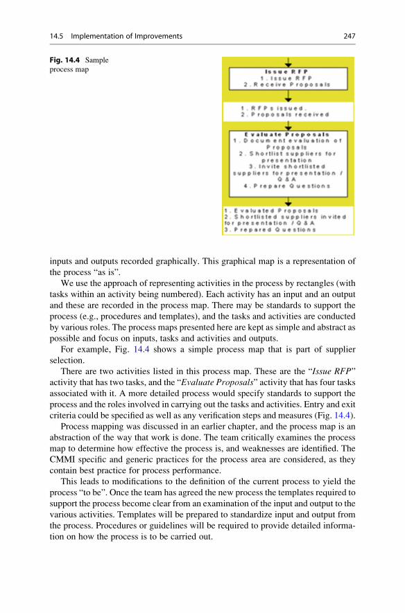
inputs and outputs recorded graphically. This graphical map is a representation of
the process “as is”.
We use the approach of representing activities in the process by rectangles (with
tasks within an activity being numbered). Each activity has an input and an output
and these are recorded in the process map. There may be standards to support the
process (e.g., procedures and templates), and the tasks and activities are conducted
by various roles. The process maps presented here are kept as simple and abstract as
possible and focus on inputs, tasks and activities and outputs.
For example, Fig. 14.4 shows a simple process map that is part of supplier
selection.
There are two activities listed in this process map. These are the “Issue RFP”activity that has two tasks, and the “Evaluate Proposals” activity that has four tasksassociated with it. A more detailed process would specify standards to support the
process and the roles involved in carrying out the tasks and activities. Entry and exit
criteria could be specified as well as any verification steps and measures (Fig. 14.4).
Process mapping was discussed in an earlier chapter, and the process map is an
abstraction of the way that work is done. The team critically examines the process
map to determine how effective the process is, and weaknesses are identified. The
CMMI specific and generic practices for the process area are considered, as they
contain best practice for process performance.
This leads to modifications to the definition of the current process to yield the
process “to be”. Once the team has agreed the new process the templates required to
support the process become clear from an examination of the input and output to the
various activities. Templates will be prepared to standardize input and output from
the process. Procedures or guidelines will be required to provide detailed informa-
tion on how the process is to be carried out.
Fig. 14.4 Sample
process map
14.5 Implementation of Improvements 247

The SEPG team is responsible for approving the processes and deliverables
produced by the improvement team. The SEPG may approve without comments, or
it may require changes to the process and deliverables prior to approval.
Once the deliverables for a process area have been approved by the SEPG they
are ready for piloting (where required) or deployment. The SEPG will decide
whether a pilot is required prior to deployment.
14.5.2 Layout of Templates
Templates are employed to support the process and it is desirable that they have a
common look and feel. The first 3–4 pages for each template should have identical
headings such as:
• Title Page
• This includes a unique document number, the date the current version was
prepared, and the release status of the document.
• It may include an abstract and an approval section.
• Version History
• This includes the history of who modified the document, the reason for
modification, and the date of modification.
• Table of Contents
• Introduction
• This includes the purpose of the document, the definition of any acronyms,
and references to other documents.
• Template Version No.
• Each template has an associated version number
There are standard templates available (e.g., the IEEE standards) for various
activities in software engineering. The organization may decide to use or tailor the
IEEE standards to meet its needs, or it may decide to devise its own Templates.
14.5.3 Layout of Procedures and Guidelines
Processes are an abstraction of the way in which work is done. They need associated
procedures or guidelines to describe in detail how the process is performed. It is
desirable that these have a common look and feel with common sections such as:
• Title Page
• Version History
• Table of Contents
• Introduction
• Overview of Process
• Process Map
• Details
• Training and Metrics
• Roles and Responsibilities
248 14 Setting Up a CMMI Initiative

14.6 Piloting the Process
The SEPG team will decide if the new processes and standards need to be piloted
prior to their deployment. This involves:
• New process is approved for pilot by the SEPG.
• Project(s) and staff are selected for the pilot.
• Training is provided to all staff that will participate on the pilot.
• The CMMI project manager will communicate the objectives of the pilot to all
participants.
The pilot then commences and the CMMI project manager will work closely
with the participants to determine the effectiveness of the new process and
standards.
• The participants will present feedback as to what went well and what went
poorly during the pilot.
• The project manager and SEPG will consider the feedback and decide whether
the process and standards are ready to be rolled out.
• The processes and standards are refined accordingly.
• If the pilot is unsuccessful the improvement team and the CMMI project
manager will analyse the reasons why and develop an appropriate strategy for
the process area.
14.7 Rolling Out Process
The SEPG team is responsible for approving the new process for rollout and for
coordinating the activities for rollout. These include:
• New process is approved for rollout by the SEPG.
• Training Material on the process is prepared by the improvement team and
approved by SEPG.
• Training is provided on the new process to all affected staff.
• The intranet site with the processes and standards will be updated to include the
new process and standards.
• The induction checklist will be updated to include induction on the new process
and standards.
• The audit checklist will be updated to audit the new process and standards.
The new process and standards will be deployed on all new projects (and
possibly on projects that have recently commenced). The post-rollout activities
may include:
• Induction to new staff on the new process
• Audits to verify that the new process is followed and effective.
• Metrics on the performance of the process are periodically reviewed to ensure
that its performance is effective.
14.7 Rolling Out Process 249

14.8 Review Questions
1. Discuss the approach suggested for software process improvement in this
chapter.
2. Discuss the continuous software process improvement cycle.
3. Describe the teams involved in a typical software process improvement
initiative.
4. Discuss the planning and scheduling required in a software process
improvement initiative.
5. Describe the activities that take place during the kick-off session of a
software process improvement initiative.
6. Describe the activities involved in process mapping.
7. Describe the purpose of pilots of new processes.
8. Describe how a new process may be rolled out to the staff in the
organization.
9. Describe how appraisals fit into the software process improvement cycle.
14.9 Summary
This chapter discussed the activities and teams required to set up a CMMI
improvement initiative, and an improvement programme involves identifying the
improvements to be made; planning the improvements; implementing the improve-
ments; pilots; deployment of the new processes; and doing it all again.
A CMMI project manager is assigned to run the initiative, and the project
manager is responsible for defining the approach to implementation and setting
up the teams involved. These include the Steering Group, the SEPG, and dedicated
improvement teams. The CMMI project manager will ensure that all team members
receive appropriate training.
The implementation consists of one or more improvement cycles. A major
improvement cycle will implement several process areas, whereas minor improve-
ment cycles may be concerned with implementing actions from an appraisal or
improvement suggestions from staff.
One of the earliest activities in an appraisal is to determine the current maturity
of the organization with respect to the CMMI model, as well as strengths and
weaknesses in its processes. The first improvement cycle will often be concerned
with the implementation of level 2 of the CMMI.
The PM will prepare the project plan and schedule, monitor and report progress,
and will manage project risks and issues. The PM works closely with the improve-
ment teams, and will participate in process mapping and in defining improved
processes.
250 14 Setting Up a CMMI Initiative

The SEPG will approve the new processes and templates and coordinate any
pilots, as well as coordinating the rollout of the new processes and standards.
A formal SCAMPI appraisal is conducted to confirm that the organization is
performing at a higher level of maturity and that the improvements are successful.
14.9 Summary 251

SCAMPI Appraisals 15
Key Topics
Appraisal Plan
Conducting an Appraisal
Objective Evidence
SCAMPI (Class A, B, C) Appraisals
Reporting the results
15.1 Introduction
Appraisals (Fig. 15.1) play an essential role in the software process improvement
programme. They allow an organization to understand its current software process
maturity, including the strengths and weaknesses in its processes. An initial
appraisal is conducted at the start of the initiative to allow the organization under-
stand its current process maturity, and to plan and prioritize improvements for the
first improvement cycle. Improvements are then implemented, and an appraisal is
typically conducted at the end of the cycle to confirm progress.
An appraisal is an independent examination of the software engineering and
management practices in the organization, and is conducted using the SCAMPI1
appraisal methodology [63]. The appraisal will identify strengths and weaknesses in
the processes and any gaps that exist with respect to the CMMI practices.
1 There are three classes of SCAMPI appraisals and these are termed Class A, B, C. They differ in
the level of formality, the cost and duration, and the reporting of the appraisal results.
G. O’Regan, Introduction to Software Quality, Undergraduate Topicsin Computer Science, DOI 10.1007/978-3-319-06106-1_15,# Springer International Publishing Switzerland 2014
253

The appraisal leader kicks off the appraisal with the opening presentation, and
the leader introduces the appraisal team,2 and presents the activities that will be
carried out in the days ahead. These will include presentations, interviews, reviews
of project documentation, and detailed analysis to determine the extent to which the
specific and generic practices have been implemented, and whether the specific and
generic goals for each process area within the scope of the appraisal are satisfied.
Sample output3 from a SCAMPI Class A CMMI level 3 appraisal is presented in
Fig. 15.2. Each column represents a CMMI process area and each row represents a
specific or generic practice. Colour coding is employed to indicate the extent to
which the specific or generic practices have been implemented. The extent of
implementation may be:
• Fully satisfied
• Largely satisfied.
• Partially satisfied
• Not satisfied
• Not rated
The appraisal leader will present the appraisal findings, and the appraisal output
may include a presentation and an appraisal report. The appraisal output summarises
Fig. 15.1 Appraisals
2 The appraisal team could be the CMMI project manager only (if the project manager is a
SCAMPI trained appraiser); alternatively, it could be an external appraiser and the CMMI project
manager. A SCAMPI Class A appraisal it could involve a large team of 4–9-appraisers (including
a SCAMPI lead appraiser) for a large organization. There is a strict qualification process to become
a SCAMPI lead appraiser, and it requires attending the official SEI CMMI and SCAMPI training
and conducting two appraisals under the direction of a qualified SCAMPI lead appraiser.3 The type of output to be provided is agreed in discussions between the appraisal sponsor and the
appraisal leader. The output may just be the strengths and improvement opportunities identified.
In other cases, the ratings may just be of the specific and generic goals rather than of he practices.
254 15 SCAMPI Appraisals
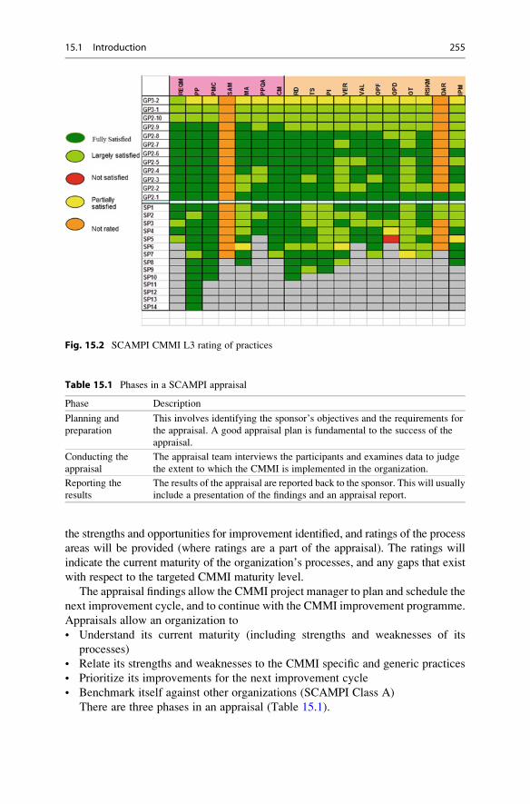
the strengths and opportunities for improvement identified, and ratings of the process
areas will be provided (where ratings are a part of the appraisal). The ratings will
indicate the current maturity of the organization’s processes, and any gaps that exist
with respect to the targeted CMMI maturity level.
The appraisal findings allow the CMMI project manager to plan and schedule the
next improvement cycle, and to continue with the CMMI improvement programme.
Appraisals allow an organization to
• Understand its current maturity (including strengths and weaknesses of its
processes)
• Relate its strengths and weaknesses to the CMMI specific and generic practices
• Prioritize its improvements for the next improvement cycle
• Benchmark itself against other organizations (SCAMPI Class A)
There are three phases in an appraisal (Table 15.1).
Fig. 15.2 SCAMPI CMMI L3 rating of practices
Table 15.1 Phases in a SCAMPI appraisal
Phase Description
Planning and
preparation
This involves identifying the sponsor’s objectives and the requirements for
the appraisal. A good appraisal plan is fundamental to the success of the
appraisal.
Conducting the
appraisal
The appraisal team interviews the participants and examines data to judge
the extent to which the CMMI is implemented in the organization.
Reporting the
results
The results of the appraisal are reported back to the sponsor. This will usually
include a presentation of the findings and an appraisal report.
15.1 Introduction 255

15.2 Planning and Requirements for the Appraisal
Good planning is essential to the success of the appraisal. The appraisal leader4 will
determine the appraisal objectives in discussions with the sponsor. The type of
appraisal to be conducted is determined, and an appraisal plan is developed to meet
the sponsor’s requirements. The appraisal leader then forms a team to conduct the
appraisal.
There are three classes of SCAMPI appraisals [1] that may be conducted, and
they vary in formality, the appraisal findings to be generated, and the output,
duration and cost. The three classes of SCAMPI appraisals (Class A, B, and C)
are defined in Fig. 15.3.
The initial evidence provided by the organization will often consist of question-
naires and Practice Implementation Indicator Descriptions (PIIDs5). The appraisal
leader will analyse the initial evidence to get a preliminary understanding of the
organization’s processes and maturity.
15.2.1 Analyze Requirements
The appraisal leader will determine the goals and objectives of the appraisal in
discussions with the sponsor. The appraisal leader may give an overview of the
CMMI and appraisals to the sponsor and relevant members of the organization.
This is to ensure that the purpose of appraisals, the various types of appraisals that
Requirements Class A Class B Class C Documents and interviews
Documents and interviews
Documents or interviews
Ratings Generated Goal ratings required
Not allowed Not allowed
Required Not required Not required
4 2 1
Lead appraiser Person trained and experienced
Person trained and experienced
Appraisal Team Leader Requirements
Minimum Team Size
Organizational Unit Coverage
Type of Objective Evidence
Fig. 15.3 SCAMPI (classes of appraisals)
4 For a formal SCAMPI Class A appraisals the appraisal team leader will need to be a qualified
SEI- SCAMPI lead appraiser.5 The PIID is a mapping between the specific and generic practices in the CMMI model and the
processes employed in the organization. It shows how the organization has implemented the
CMMI. It is produced prior to the appraisal.
256 15 SCAMPI Appraisals
may be conducted and the output that may be produced are understood. This is
essential when the organization is relatively new to software process improvement.
It will be explained where appraisals fit into software process improvement,
and how the output from the appraisal is used in the next improvement cycle.
The objectives of the appraisal should be realistic, and constraints such as cost,
schedule and effort determined.
The business goals of the software process improvement initiative may influence
the scope and type of appraisal to be conducted. The business goals may include:
• Reducing costs of software development
• Delivery software consistently on time
• Delivering high-quality software
• Delivering software fast to market ahead of competitors
• Marketing benefit of CMMI maturity level as a differentiator to its competitors
A software process improvement initiative will generally focus on improve-
ments to those processes in the organization that will lead to the greatest business
benefit. The appraisal is an objective way to determine if these processes have
actually improved, as well as determining their actual maturity. Some companies
may be interested in the marketing benefit of a CMMI maturity level rating, and
may wish to benchmark themselves against other companies. They will generally
be interested in a formal SCAMPI Class A appraisal.
The scope of the appraisal determines the CMMI process areas that will be
appraised; the parts of the organization to be examined; the participants; and the
projects and support functions involved.
The sponsor will decide on the appraisal outputs to be produced, and this may
include strengths and weaknesses in the processes; ratings of the process areas
appraised; a final findings presentation with recommendations; and an appraisal
report. The appraisal input gathered from the discussions will include:
• Identity of appraisal sponsor
• Appraisal leader and team
• Participants in appraisal
• Objectives of appraisal
• Scope of appraisal
• Selected projects
• Constraints
• Confidentiality requirements
• Appraisal outputs
The sponsor and appraisal leader verbally agree the appraisal input which is then
documented in the appraisal plan.
15.2.2 Develop Appraisal Plan
The appraisal plan is prepared by the appraisal leader, and it describes the scope of
the appraisal and how it will be conducted. It includes the input gathered in
discussions with the appraisal sponsor such as:
15.2 Planning and Requirements for the Appraisal 257
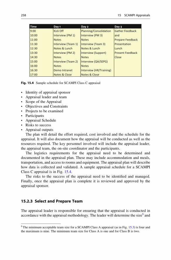
• Identity of appraisal sponsor
• Appraisal leader and team
• Scope of the Appraisal
• Objectives and Constraints
• Projects to be examined
• Participants
• Appraisal Schedule
• Risks to success
• Appraisal outputs
The plan will detail the effort required, cost involved and the schedule for the
appraisal. It will also document how the appraisal will be conducted as well as the
resources required. The key personnel involved will include the appraisal leader,
the appraisal team, the on-site coordinator and the participants.
The logistics requirements for the appraisal need to be determined and
documented in the appraisal plan. These may include accommodation and meals,
transportation, and access to rooms and equipment. The appraisal plan will describe
how data is collected and validated. A sample appraisal schedule for a SCAMPI
Class C appraisal is in Fig. 15.4.
The risks to the success of the appraisal need to be identified and managed.
Finally, once the appraisal plan is complete it is reviewed and approved by the
appraisal sponsor.
15.2.3 Select and Prepare Team
The appraisal leader is responsible for ensuring that the appraisal is conducted in
accordance with the appraisal methodology. The leader will determine the size6 and
Time Day 1 Day 2 Day 39:00 Kick Off Planning/Consolidation Gather Feedback10:00 Interview (PM 1) Interview (PM 3) and11:00 Notes Notes Prepare Feedback11:30 Interview (Team 1) Interview (Team 3) Presentation12:30 Notes & Lunch Notes & Lunch Lunch13:30 Interview (PM 2) Interview (Support) Present Feedback14:30 Notes Notes Close15:00 Interview (Team 2) Interview (QA/SEPG)16:00 Notes Notes16:30 Demo Intranet Interview (HR/Training)17:00 Notes & Close Notes & Close
Fig. 15.4 Sample schedule for SCAMPI Class C appraisal
6 The minimum acceptable team size for a SCAMPI Class A appraisal (as in Fig. 15.3) is four and
the maximum is nine. The minimum team size for Class A is one and for Class B is two.
258 15 SCAMPI Appraisals
composition of the team, and will select team members who are appropriately
qualified and have sufficient knowledge and experience to conduct the appraisal
effectively. Any knowledge and skill gaps will need to be identified, and addressed
by training7 prior to the appraisal.
The methodology requires that the team has sufficient software engineering and
management experience. Team members also need good verbal and written com-
munication skills to enable them to carry out their roles effectively.
The appraisal leader will introduce the team members to one another, and will
give the team an overview of the goals of the appraisal; its scope; the appraisal plan;
and the approach to the appraisal. This orientation will enable the appraisal team to
carry out their assigned roles effectively.
The initial information provided by the organization (e.g., completed question-
naires and PIIDs) will be analyzed, and the data collection and validation methods
and tools to be employed during the appraisal discussed. There are confidentiality
requirements to be preserved during an appraisal. For example, everything that is
said by individuals during the interviews is treated in the strictest confidence, and
appraisal findings are not attributed to individuals.
There are several roles involved in the appraisal including the on-site coordi-nator8 who takes care of the logistics to support the appraisal team leader; the
librarian who manages the inventory of appraisal documents; mini-teams who are
responsible for data collection for their assigned process areas; facilitators who
conduct the interviews; and timekeeper who keeps the interview on time.
15.2.4 Obtain and Analyze Initial Evidence
The organization will provide initial information to the appraisal leader prior to the
appraisal to show how it has implemented the CMMI. This helps the appraisal team
to understand how the organization has implemented the various practices in the
CMMI model, and assists the team in preparing a data collection plan to verify
the implementation. The initial evidence may include completed questionnaires,
relevant presentations, and a PIID mapping between the CMMI specific and generic
practices and the process assets of the organization.
This initial evidence is analyzed by the team to enable them to understand the
objective evidence available for the specific and generic practices. An inventory of
the evidence available for the various CMMI practices is prepared, and the ade-
quacy and completeness of the information provided is determined. This may result
in the need for additional data which is then input into the data collection plan.
7 The appraisers need to have received appropriate training on the CMMI reference model and on
the SCAMPI appraisal methodology.8 The CMMI project manager is responsible for project managing the CMMI implementation , and
may carry out the role of onsite coordinator.
15.2 Planning and Requirements for the Appraisal 259

There is a need for objective evidence to substantiate implementation of every
practice within the scope of the appraisal, and for every project instance of that
practice. The extent to which the practice has been implemented is judged by
practice implementation indicators, given in Table 15.2.
It is important to collect as much objective evidence as possible prior to the
appraisal, as this will reduce the time required for discovery activities during the
appraisal. The discovery activities are concerned with looking for evidence to
support practice implementation, and an efficient on-site appraisal will focus
more on verification activities rather than on discovery activities.
15.2.5 Prepare for Conducting Appraisal
The appraisal leader will conduct an appraisal readiness review to judge the extent
to which the organization is ready for the appraisal. There is no point in going ahead
with the appraisal if the organization is not ready or is insufficiently prepared.
The sponsor and appraisal leader will consider the feasibility of the appraisal
plan, and will decide on whether to continue with the appraisal as planned, to
re-plan accordingly, or in a worst case scenario to cancel the appraisal.
The appraisal leader will judge whether the preliminary data is available, and
whether the appraisal team has been formed and appropriately trained. The logistics
will need to be suitably handled and the risks to the appraisal identified and
managed.
The PIIDs will detail the coverage of the CMMI specific and generic practices,
and it is reasonable to expect few significant coverage gaps prior to the appraisal.
The PIID will refer to documents and evidence that need to be accessible to the
appraisers. The appraisers need a verification strategy to verify the objective
evidence that is available for practices, as well as a discovery strategy to find
objective evidence for practices that have no available objective evidence. The
verification and discovery activities to take place during the appraisal are docum-
ented in the data collection plan.
The data collection plan may be documented in a variety of deliverables
(e.g., interview schedule and participants and scripted interview questions).
It may include a spreadsheet with the CMMI practices or questions listed vertically
Table 15.2 Indicators of practice implementation
Indicator Description
Direct
Artifact
Tangible output of the practice (e.g., typical work products in CMMI model).
Indirect
Artifact
Artifacts that are a consequence of performing the process (e.g., meeting minutes),
but not necessarily the purpose for which it is performed.
Affirmation Oral or written statements confirming the performance of a practice.
260 15 SCAMPI Appraisals

and sources of information listed horizontally. Data on every practice within the
scope of the appraisal is required.9
The appraisal leader will determine the participants required at each interview
and the documents to be reviewed. The roles and responsibilities of team members
in data collection activities will be documented in the data collection plan.
15.3 Conducting the Appraisal
This phase of the appraisal is concerned with on-site activities to gather data on
the extent to which the specific and generic practices have been implemented.
It involves gathering and examining the objective evidence, as well as documenting
and verifying the data. The preliminary findings are generated and presented to the
appraisal participants to get feedback in order to validate the data and findings.
Additional data is then gathered and the final appraisal results prepared. The
activities involved include:
• Prepare Participants
• Collect Objective Evidence
• Examine Objective Evidence
• Verify Objective Evidence
• Validate Objective Evidence
• Generate Appraisal Findings
The appraisal participants will receive appropriate training on the appraisal process
and their role in it. The appraisal team members take notes and gather objective
evidence during the various data collection activities. The objective evidence is
then reviewed and consolidated, related to the specific and generic practices,
critically examined and documented, and verified and validated. The extent to
which the CMMI practices are implemented is determined.
Preliminary findings are prepared and validated and the final appraisal results are
then prepared.
15.3.1 Prepare Participants
The onsite coordinator (this may be the CMMI project manager or the quality
manager) will give appropriate orientation to the appraisal participants prior to the
appraisal to ensure that they understand the purpose of the appraisal and their role in
it. This will be the first experience of an appraisal for many in the organization, and
so the participants need to understand the process and the required behaviours:
• Professional behaviour at all times
• Punctuality in attendance for interviews
9Data is required for every project instantiation for practices addressing processes at the project
level. One instantiation is sufficient for practices addressing processes at the organization level.
15.3 Conducting the Appraisal 261

• Openness and honesty in answering questions
• Acting promptly on requests to provide additional material
• Awareness of the confidentiality requirements
• Awareness that the appraisal findings will not be attributed to individuals or
specific projects.
The participants need to be aware of the meetings and interviews that they need
to attend. All participants will attend the opening and closing sessions, and will
attend their own specific interview(s), and the feedback session(s).
The sponsor introduces the appraisal leader at the opening session, and the leader
will set the context and expectations for the appraisal, and describes the activities
that will take place in the days ahead. The leader gives a brief overview to the
participants on the appraisal process and schedule, and the appraisal team is
introduced. The opening presentation will typically cover:
• Overview of appraisal
• Appraisals and Process Improvement
• Process Areas within scope of appraisal
• Projects to be reviewed
• Activities in appraisal
• Participants in Appraisal
• Confidentiality
• Appraisal Schedule
• Output from appraisal
The information provided by participants will be treated in the strictest con-
fidence by the appraisal team, and that none of the appraisal findings will be
attributed to individuals or projects. This is important, as otherwise participants
may be reluctant to share information.
15.3.2 Examine Objective Evidence
The accuracy of the appraisal findings is dependent on the accuracy of the informa-
tion collected by the appraisal team. The team needs to collect adequate infor-
mation on how the organization does its work, and the information gathered needs
to be related to the CMMI specific and generic practices. This requires that the
appraisal team understands how the organization has implemented the CMMI, and
has objective evidence of specific and generic practice implementation.
The data collection needs to be well planned and tracked and it will be revised
appropriately during the appraisal to reflect new information needs. The data
collection plan consists of:
• Appraisal schedule
• Interview schedule
• Document list
• Interview questions
262 15 SCAMPI Appraisals
The appraisal team will continually manage the data collected, and plan new
data collection in line with information needs. The data collection sources include:
• Interviews with appraisal participants
• Reviews of documentation
• Presentations from staff
The interviews need to be well planned as they have a limited amount of time
to determine specific evidence (e.g., oral affirmation on the way the process is
performed) from the participants. The planning requires the preparation of scripted
questions to ensure that the interview is focused and achieves its objectives within
the time constraints. Interviews also allow dynamic data gathering, with the inter-
viewer able to branch off to discuss other related topics.
The information provided at an interview is treated in the strictest confidence,
and the appraisal findings will not be attributed to individuals or projects. There
will be separate interviews for:
• Project Managers
• Project Teams
• Functional Area Representatives (FAR)
• Managers
• Specific Groups (SEPG Team, QA, etc.).
Often, one of the appraisal team members will lead the interview with some or
all of the other appraisers being present, listening and taking notes. The planned
set of interviews will be defined in the data collection plan, and re-planning will
take place as appropriate. There may be a need for extra on-call interviews or some
of the planned interviews may be cancelled if sufficient objective evidence is
available.
Documentation reviews give the appraisal team a clearer understanding of what
practices are performed in the organization. This includes insight into how the
process is performed, the extent to which it is performed, as well as allowing
explicit deliverables produced to be examined. Most of the direct artefacts used
as indicators of practice implementation are documents.
There are three levels of documents that will typically be examined during the
appraisal. These are:
• Organization documents
• Project documents
• Implementation documents
The organization documents include policies, processes and procedures; the
project documents include the deliverables produced during the project for each
project instantiation; and the implementation documents provide an audit trail
of the processes used. The appraisal team will maintain an inventory of the
documents used.
Presentations allow the organization to explain how particular practices are
performed. The appraisal team will need to analyse the information obtained during
the various data collection activities to:
• Judge if the information collected is acceptable as objective evidence
• Relate it to the corresponding practices in the model.
• Relate evidence to the appropriate part of the organization unit
15.3 Conducting the Appraisal 263

The results of data collection will often be recorded on electronic tools, as the
inventory of the collected evidence. The appraisal team will closely monitor
progress with the data collection activities, and as appraisals have a limited amount
of time available it is essential that the data collection activities are focused and
efficient.
Finally, once the team has examined, verified and validated all of the required
data it is in a position to generate the appraisal findings, and where applicable, to
generate ratings for the organization.
15.3.3 Document Objective Evidence
This part of the appraisal is concerned with note taking; reviewing and con-
solidating notes; relating the notes to the corresponding practices in the CMMI
model; and documenting practice implementation and the strengths and weaknesses
identified. The notes taken by the team members during the data gathering sessions
are reviewed at the end of each session, and significant items relating to one or more
practices tagged. The notes record the particular data gathering session as well as
the participants.
The consolidation of the notes allows the appraisal team members to have a
common understanding of the data collected to date, as well as identifying further
data collection needs. The presence or absence of objective data for each model
practice for each process area within scope needs to be done for each project
instantiation. The gaps identified in the implemented processes with respect to the
practices in the CMMI model are documented.
It is essential that the data collection, consolidation and documentation activities
be conducted in a timely manner. An inventory (usually an electronic spreadsheet
tool or a manual wall chart tool) of the objective evidence available for each
specific and generic practice for each project instantiation within the scope of the
appraisal is maintained.
The inventory allows the status of the data collection and consolidation activities
to be determined, and this includes the practices for which there is sufficient
objective evidence available, and those that have insufficient or missing evidence.
The data collection plan needs to be updated appropriately to reflect additional data
collection needs. The inventory will record:
• Project to which data applies
• Specific or Generic practice to which it applies
• Type of evidence (Direct, Indirect, Affirmation)
• Whether implies presence or absence of objective evidence
Often, in large formal appraisals, team members are assigned responsibilities for
the collection and documentation of objective evidence for one or more process
areas. This usually involves the formation of mini-teams with two or three members
to obtain and document the objective evidence for their assigned process areas.
The raw notes taken by the appraisers are treated as confidential information
and are not disclosed to anyone outside of the appraisal team. Team members will
destroy their notes at the end of the appraisal to ensure that information cannot be
attributed to individuals.
264 15 SCAMPI Appraisals

15.3.4 Verify Objective Evidence
This is concerned with verifying the implementation of the organization’s practices
for each project instantiation, as well as determining and documenting the extent
to which the practices are implemented. The implementation of each practice is
verified for each project instantiation, with exemplary implementations highlighted
as strengths to be included in the appraisal findings.
The appraisal team uses the initial objective evidence provided by the organiza-
tion to understand how the CMMI practices are implemented. The team then
gathers data to confirm that the practices are actually implemented as defined,
and this may reveal gaps in the implementation that were not apparent in the initial
evidence provided. The implemented practices are then compared to the specific
and generic practices in the CMMI model, and additional gaps may be identified.
The gaps in the implementation are recorded, and become part of the appraisal
findings.
The appraisal teammust verify that each project within the scope of the appraisal
has objective evidence of implementation of the specific or generic practices
(reflecting project activities). The appraisal team will:
• Verify the appropriateness of each direct artefact provided for practices within
appraisal scope
• Verify the appropriateness of each indirect artefact provided
• Verify appropriateness of affirmations
• Verify that implementation of each practice (within scope) is supported by direct
artefacts and corroborated by indirect artefacts or affirmations
• Obtain oral affirmation corresponding to each specific and generic goal within
scope of appraisal
• Generate the preliminary findings including the strengths identified and gaps in
the implemented practices.
Much of the evidence required to perform verification is provided prior to the
appraisal. The main focus of the data collection activities is to allow the appraisal
team to verify that the intended practices are implemented across the organization
unit and to identify any gaps in the implementation.
The appraisal team then characterizes the extent to which the CMMI practices
are implemented for each project instantiation, and derives an aggregate rating to
characterize the extent of implementation in the organization. The extent of imple-
mentation of a practice is:
• Fully implemented (FI)
• Largely implemented (LI)
• Partially implemented (PI)
• Not implemented (NI)
The extent of implementation of the practice is judged by:
• The presence or absence of direct artefacts and their adequacy.
• The presence or absence of indirect artefacts and affirmations to confirm the
implementation
• Any weaknesses in practice implementation identified.
15.3 Conducting the Appraisal 265
The aggregate organization rating for each practice is determined from the rating
of the practice for each project instantiation. For example, if all project instan-
tiations are fully implemented then the organization rating is fully implemented.
15.3.5 Validate Preliminary Findings
The appraisal team will present preliminary findings to members of the organiza-
tion to ensure that they are an accurate reflection of the organization. This is mainly
a data collection activity, and the goal is to validate the appraisal team’s under-
standing of the processes implemented in the organization. Feedback and additional
evidence will be requested and used in the formulation of the final findings.
The preliminary findings detail the practice implementation gaps identified as
well as strengths noted by the appraisal team. Every model practice characterized
at the organization level as not implemented, partially implemented or largely
implemented will have a preliminary finding associated with it.
The appraisal team will issue a request for further information for areas where
the appraisal team has insufficient objective evidence available.
15.3.6 Generate Appraisal Results
The appraisal team will rate specific and generic goal satisfaction based on the
extent of practice implementation throughout the organization. The extent of
practice implemented is judged by the validated data collected, including direct
and indirect artefacts and oral affirmation objective evidence. Once the goals have
been rated the process areas may be rated and then the overall maturity level
determined.
A goal is considered satisfied if the practices associated with that goal are
appropriately implemented. Any gaps are considered and the appraisal team
makes a judgment made on whether these gaps threaten the ability to achieve the
associated goal. All associated practices must be rated as largely or fully
implemented, and any identified weaknesses must not have a significant impact
on goal achievement. For any goals that are rated as not satisfied the appraisal team
will detail how the weaknesses identified led to this rating.
Once the goals have been rated the team are then in a position to judge the
satisfaction of the process areas within the appraisal scope. Process area satisfaction
is closely related to goal satisfaction, and a process area is rated satisfied if all of its
specific and generic goals up to the targeted maturity level are rated satisfied.
The appraisal team is then in a position to judge the maturity level of the
organization. This is based on the ratings of the process areas within the scope of
the appraisal. The maturity level determined is the highest level at which all process
areas contained at that maturity level and lower levels are satisfied.10
10 Generic goal 3 must also be rated for all of the level 2 process areas for a level 3 rating.
266 15 SCAMPI Appraisals

The appraisal team is then in a position to prepare the final appraisal findings
including:
• Documenting the final findings
• Documenting the ratings (where ratings are part of the appraisal)
• Preparing (where applicable) the Appraisal Disclosure Statement (ADS) for the
CMMI Stewart at the SEI.
15.4 Reporting the Results
The results of the appraisal are presented to the sponsor and the participants.
The strengths and weaknesses of the processes are presented, as well as the ratings
of the process areas (where these are part of the appraisal). The appraisal results
need to be credible, as they will be used for continuous improvement.
The appraisal findings are intended to promote action and occasionally a sepa-
rate executive session is conducted with senior management. The purpose of this
session is to discuss the appraisal results, and to facilitate the preparation of an
action plan to address the findings.
15.4.1 Deliver Appraisal Results
The findings will be presented to the appraisal participants. The appraisal sponsor is
advised of the appraisal results prior to the presentation as a matter of courtesy and
to prevent any surprises. The appraisal leader will provide the appraisal findings to
the appraisal sponsor, and the findings will be signed by the appraisal leader and
team. The appraisal findings will include:
• Summary of appraisal process
• Summary of strengths and weaknesses for each process area
• Ratings (where this is part of appraisal)
Any statements of weaknesses will adhere to the confidentiality requirements,
and will not be attributed to projects or individuals. The appraisal leader and team
will sign the appraisal findings to indicate their agreement with them.
An executive session may be conducted between the sponsor and appraisal
leader to clarify any issues from the appraisal, and to help the sponsor and senior
management understand the process weaknesses identified. This helps to ensure
that management are sufficiently informed to act appropriately on the findings.
15.4.2 Archive Appraisal Results
Important data and records from the appraisal will be preserved and confidential
information disposed of securely. Any lessons learned from the appraisal will be
used to improve the appraisal process.
15.4 Reporting the Results 267

The information archived will include the appraisal plan and appraisal results.
All notes taken by appraisers will be destroyed. The appraisal record will be
delivered to the appraisal sponsor and will include:
• Dates of the appraisal
• Appraisal input
• Appraisal plan
• Objective evidence to support goal ratings
• Characterization of practice implementation
• Appraisal method
• Final findings
• All ratings (goals, practices and maturity levels)
The ADS record will be created and submitted to the CMMI steward at the SEI
for formal SCAMPI Class A appraisals.
15.5 Review Questions
1. Discuss the purpose of appraisals and how they fit into the software
process improvement cycle.
2. Describe the three phases in an appraisal.
3. Describe the three classes of SCAMPI appraisals.
4. Discuss the difference between data discovery and data verification
activities in an appraisal.
5. Describe the activities that take place in planning the appraisal.
6. Describe the activities that take place during the appraisal.
15.6 Summary
Appraisals play a key role in software process improvement and are an essential
part of the improvement programme. They allow an organization to understand its
current software process maturity, including its strengths and opportunities for
improvement. An initial appraisal is generally conducted at the start of the initiative
to allow the organization plan and prioritize improvements for the first improve-
ment cycle. Improvements are then implemented, and an appraisal is typically
conducted at the end of the cycle to confirm progress.
An appraisal is an independent examination of the software engineering and
management practices in the organization and will identify any gaps that exist with
respect to the targeted level in the CMMI. There are three phases in an appraisal:
planning the appraisal; conducting the appraisal; and reporting the results.
The appraisal leader will determine the appraisal requirements and objectives in
discussions with the sponsor. The type of appraisal to be conducted is determined,
and an appraisal plan is developed to meet the sponsor’s requirements. The appraisal
268 15 SCAMPI Appraisals

leader then forms a team to conduct the appraisal and the participants involved in the
appraisal receive appropriate training on the appraisal process and their role in it.
The on-site activities will gather data to determine the extent to which the CMMI
practices within the scope of the appraisal have been implemented. It involves
gathering and examining the objective evidence, and documenting and verifying
the data. The team makes notes and gathers objective evidence during the various
data collection activities (e.g., interviews, presentations, and reviews of documen-
tation). The objective evidence is then reviewed and consolidated, related to the
CMMI practices, critically examined and documented, verified and validated. The
extent to which the CMMI practices are implemented is determined. Preliminary
findings are then prepared and validated by members of the organization. The final
appraisal results are then prepared.
The results of the appraisal are then presented to the sponsor and the participants.
The strengths and weaknesses identified with the processes will be presented, as
well as the ratings of the process areas (where these are part of the appraisal).
The appraisal results are used for continuous process improvement. An action plan
is prepared to address the appraisal findings from the various.
15.6 Summary 269

Software Engineering Tools 16
Key Topics
Microsoft Project
COCOMO
Planview Enterprise
IBM Rational DOORS
Rational Software Modeler
LDRA Testbed
Integrated Development Environment
Sparx Enterprise Architect
HP Quality Center
16.1 Introduction
The goal of this chapter is to give a flavour of a selection of tools1 that can support
the organization in various software engineering activities. Tools for project man-
agement, requirements management, configuration management, design and devel-
opment, testing, and so on are considered. The organization will generally choose
tools to support the process rather than choosing a process to support the tool.2
Mature organizations will employ a structured approach to the introduction of
new tools. First, the requirements for a new tool are specified and the options to
1 The list of tools discussed in this chapter is intended to give a flavour of what tools are available,
and the inclusion of a particular tool is not intended as a recommendation of that tool. Similarly,
the omission of a particular tool should not be interpreted as disapproval of that tool.2 That is, the process comes first then the tool rather than the other way around.
G. O’Regan, Introduction to Software Quality, Undergraduate Topicsin Computer Science, DOI 10.1007/978-3-319-06106-1_16,# Springer International Publishing Switzerland 2014
271

satisfy the requirements are considered. These may include developing a tool
internally; outsourcing the development of a tool to a third party supplier; or
purchasing a tool off the shelf from a vendor.
The sample tool evaluation in Table 16.1 lists all of the requirements vertically
that the test tool is to satisfy, and the tools to be evaluated and rated against each
requirement are listed horizontally. Various rating schemes may be employed and
in the example presented here, a simple numeric rating scheme is employed to rate
the effectiveness of the tool under evaluation, to indicate the extent to which the
tool satisfies the particular requirement. The chosen tool in this example is Tool k asit is the most highly rated of the evaluated tools.
Several candidate tools will be identified and considered prior to selection, and
each candidate tool will be evaluated to determine the extent to which it satisfies the
specified requirements. An informed decision is then made and the proposed tool
will be piloted prior to its deployment. The pilot provides feedback on its suitabil-
ity, and the feedback will be considered prior to a decision on full deployment, and
whether any customization is required prior to roll out.
Finally, the users are trained on the tool, and the tool is rolled out throughout the
organization. Support is provided for a period post deployment. First, we consider
tools for project management.
16.2 Tools for Project Management
There are several tools to support the various project management activities such as
estimation and cost prediction, planning and scheduling, monitoring risks and
issues, and managing a portfolio of projects. These include tools such as Microsoft
Project which is a powerful project management scheduling tool widely used by
project managers throughout the world. Small projects may employ a simpler tool
such as Microsoft Excel for their project scheduling activities.
The Constructive Cost Model (COCOMO) is a cost prediction model developed by
Barry Boehm [7] to estimate effort, schedule and cost for small and medium
projects. It is based on an effort estimation equation that calculates the software
development effort in person-months from the estimated project size. The effort
estimation calculation is based on the estimate of a project’s size in thousands of
Table 16.1 Tool
evaluation tableTool 1 Tool 2 . . . Tool k
Requirement 1 8 7 9
Requirement 2 4 6 8
. . . . . . . . . . .
. . . . . . . . . . .
Requirement n 3 6 8
Total 35 38 . . . 45
272 16 Software Engineering Tools

source lines of code (SLOC3). The accuracy of the tool is limited as there is a great
deal of variation among teams due to differences in the expertise and experience of
the personnel in the project team.
There are several commercial variants of the tool including the COCOMO Basic,
Intermediate and Advanced Models. The Intermediate Model includes several cost
drivers to model the project environment, and each cost driver is rated. There are
over 15 cost drivers used and these include product complexity, reliability, and
experience of personnel as well as programming language experience. The COCOMO
parameters need to be calibrated to reflect the actual project development environ-
ment. The effort equation used in COCOMO is given by:
Effort ¼ 2:94 *EAF * KSLOCð ÞE ð16:1ÞIn this equation, EAF refers to the effort adjustment factor that is derived from
the cost drivers, and E is the exponent that is derived from the five scale drivers.4
The Costar tool is a commercial tool that implements the COCOMO Mode, and it may
be used on small or large projects. It needs to be calibrated to reflect the particular
software engineering environment, and this will enable more accurate estimates to
be produced.
Microsoft Project (Fig. 3.2) is a project management tool that is used for
planning, scheduling and charting project information. It enables a realistic project
plan to be created, and the plan is updated regularly during the project to reflect
actual progress, and the project is re-planned as appropriate. We discussed project
management in Chap. 3.
A project is defined as a series of steps or tasks to achieve a specific goal. The
amount of time that it takes to complete a task is termed its duration, and tasks are
performed in a sequence determined by the nature of the project. Resources such as
people and equipment are required to perform a task. A project will typically consist
of several phases such as planning and requirements; design; implementation; testing
and closing the project.
The project schedule (Fig. 3.2) shows the tasks and activities to be carried out
during the project; the effort and duration of each task and activity; the percentage
complete of each task, and the resources needed to carry out the various tasks. The
schedule shows how the project will be delivered within the key project parameters
such as time, cost and functionality without compromising quality in any way.
The project manager is responsible for managing the schedule and will take
corrective action when project performance deviates from expectations. The project
schedule will be updated regularly to reflect actual progress made, and the project
re-planned appropriately.
3 SLOC includes delivered source lines of code created by project staff (excluding automated code
generated and also code comments).4 The five scale drivers are factors contributing to duration and cost and they determine the
exponent used in the Effort equation. Examples include team cohesion and process maturity.
16.2 Tools for Project Management 273

Project portfolio management (PPM) is concerned with managing a portfolio of
projects, and it allows the organization to choose the optimal mix and sequencing of
its projects to yield the greatest business benefit to the organization.
It analyses the project’s total expected cost, the resources required, the schedule,
the benefits that will be realized as well as interdependencies with other projects in
the portfolio. This allows project investment decisions to be made methodically to
deliver the greatest benefit to the organization. The approach moves away from the
normal once off analysis of an individual project proposal, to the analysis of a
portfolio of projects. PPM tools aim to manage the continuous flow of projects from
concept all the way to completion.
There are several commercial portfolio management tools available from various
vendors. These include Clarity PPM from Computer Associates, Change Point from
Compuware, RPM from IBM Rational, PPM Center from HP, and Planview Enter-
prise from Planview. It is not possible to discuss of all of these portfolio management
tools, and the discussion in this section is limited to the Planview Enterprise tool.
Planview Enterprise Portfolio Management allows organizations to manage
projects and resources across the enterprise, and to align their initiatives for
maximum business benefit. It provides visibility into and control of project
portfolios, and allows the organization to prioritize and manage its projects and
resources. This allows it to make better investment decisions, and to balance its
business strategy against its available resources. Planview helps an organization to
optimize its business through eight key capabilities listed in Table 16.2.
Planview allows key project performance indicators to be closely tracked. This
includes dashboard views of variances of cost, effort and schedule, and the analysis
and reporting is described in Fig. 16.1.
Planview includes Process Builder (Fig. 16.2), which allows modelling and
management of enterprise wide processes. It provides improved tracking, control
and audit capabilities in key process areas such as requirements management and
product development, as well as satisfying key regulatory requirements.
The organization may define and model its process in Process Builder, and this
includes process adoption, compliance and continuous improvement. The function-
ality includes:
• Process Design
• Process Automation
• Process Measurement
• Process Auditing
Next, we will consider tools to support requirements development and
management.
16.3 Tools for Requirements
There are several tools available to assist organizations in carrying out requirements
development and management. These tools assist in eliciting requirements from the
stakeholders; modelling requirements; verifying and validating the requirements;
managing the requirements throughout the lifecycle; and providing traceability of
274 16 Software Engineering Tools

Table 16.2 Key capabilities of Planview Enterprise
Capability Description
Strategic planning Define mission, objectives and strategies.
Allocate funding/staffing for chosen strategy
Automate and manage strategic process
Investment analysis Devise strategic long-term plans
Identify key criteria to evaluate initiatives
Optimize strategic and project investments to maximize business benefit
Capacity management Balance resources with business demands
Ensure capacity supports business strategy
Align top down and bottom up planning
Forecast resource capacity
Demand management Request work and Check status
Review lifecycles
Project management Scope, schedule and execution of work
Track/report time worked against projects
Track and manage risks and issues
Track/display performance and trend analysis
Financial management Collaborate to better forecast cost
Monitor spending
Resource management Balance portfolios/assign people efficiently
Improve forecasting
Keep staff productive
Change management Determine impact of change on schedule/cost
Effectively manage change
Fig. 16.1 Dashboard views in Planview Enterprise
16.3 Tools for Requirements 275

the requirements to the design and test cases. Table 16.3 gives a small selection of
some of the tools that are available.
DOORS® (Dynamic Object-Oriented Requirements System) is a requirements
management tool developed by IBM Rational. It allows the stakeholders to actively
participate in the requirements process, and aims to optimize requirements
Fig. 16.2 Planview Process Builder
Table 16.3 Tools for requirements development and management
Tool Description
DOORS (IBM/Rational) This is a Requirements Management tool developed by Telelogic
(which is now part of IBM/Rational).
Requisite Pro
(IBM/Rational)
This is a Requirements Management and Use Case management tool
developed by IBM/Rational
Enterprise Architect
(Sparx Systems)
This is a UML analysis and design tool that covers requirements
gathering, analysis and design, and testing and maintenance. It was
developed by Sparx Systems and integrates requirements
management with the other software development activities.
CORE (Vitech) This is a requirements tool developed by Vitech and may be used for
modelling and simulation.
Integrity (MKS) This tool was developed byMKS and enables organizations to capture
and validate software requirements, and to link them to downstream
development and testing activities.
276 16 Software Engineering Tools

communication, collaboration and verification. High-quality requirements help the
organization in reducing costs5 and in meeting their business objectives.
The tool can capture, link, trace, analyse, and manage changes to the requirements.
It enhances communication and collaboration to ensure that the project conforms to
the customer requirements, as well as compliance to regulations and standards.
Requirements are documented in a way that is easy to interpret and navigate. It is
easy to locate information within the database, and the user requirements are
recorded in a document style showing each individual requirement. It provides
views of the list with assigned identifiers and also an Explorer-like navigation tree.
The tool employs links to support traceability of the requirements, and these are
traversed with a simple click of the mouse to the corresponding object. The links are
easy to create by dragging and dropping; e.g., a new link from the user requirements
to the system requirements is created in this way. The tool provides dynamic
reporting on traceability, and filters may be employed to ensure that traceability
is complete. Traceability is essential in demonstrating that the requirements have
been implemented and tested.
The management of change is an important part of the requirements process.
The DOORS tool supports changes to requirements and allows an impact analysis of
the proposed changes to be performed. It allows changes that could impact other
requirements or design items and test cases to be tagged. The DOORS® tool
(Fig. 16.3) provides:
• A comprehensive requirements management environment
• Web browser access to the requirements database
• Manages changes to requirements
• Scalable solution for managing project scope and cost
• Traceability to design items, test plans and test cases
• Active engagement from stakeholders
• Integrates with other IBM Rational tools
There are several other IBM Rational tools that may be integrated with DOORS®.
These include the IBM Rational System Architect, Requirements Composer,
Rhapsody, and Quality Manager.
IBM Rational RequisitePro is a requirements management tool that allows
requirements to be documented with familiar document-based methods, and it
provides capabilities such as requirements traceability and impact analysis.
Requirements are managed throughout the lifecycle, and changes to the requirements
controlled.
The CORE product suite (developed by Vitech) has functionality for requirements
management, modelling and simulation, and verification and validation. It supports
5A good requirements process will enable high-quality requirements to be consistently produced,
and the cost of poor quality is reduced as wastage and rework is minimized. The requirements are
the foundation of the system and if they are incorrect then the delivered system will not be fit for
purpose.
16.3 Tools for Requirements 277

UML activity and sequence diagrams which enable the desired behaviour and flow
of control to be captured and analysed. The tool provides:
• Comprehensive end-to-end system traceability
• Change impact analysis
• Multiple modelling notations with integrated graphical views
• System simulation based on behavioural models
• Generation of Documentation from the database
The Integrity tool was developed byMKS and it enables organizations to capture
and validate software requirements. It enables them to link the requirements to
downstream development and testing activities, and to manage changes to the
requirements. Next, we will consider tools to support software design and
development.
16.4 Tools for Design and Development
This section describes tools available to support software design and development
activities. The software design includes the high-level architecture of the system, as
well as the lower level design and algorithms. Table 16.4 gives a small selection of
some of the tools that are available.
IBM Rational Software Modeler® (RSM) (Fig. 16.4) is a UML-based visual
modelling and design tool. It promotes communication and collaboration during
Fig. 16.3 IBM Rational DOORS tool
278 16 Software Engineering Tools
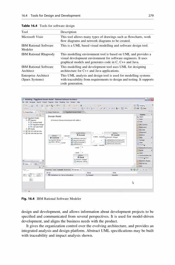
design and development, and allows information about development projects to be
specified and communicated from several perspectives. It is used for model-driven
development, and aligns the business needs with the product.
It gives the organization control over the evolving architecture, and provides an
integrated analysis and design platform. Abstract UML specifications may be built
with traceability and impact analysis shown.
Table 16.4 Tools for software design
Tool Description
Microsoft Visio This tool allows many types of drawings such as flowcharts, work
flow diagrams and network diagrams to be created.
IBM Rational Software
Modeler
This is a UML based visual modelling and software design tool.
IBM Rational Rhapsody This modelling environment tool is based on UML and provides a
visual development environment for software engineers. It uses
graphical models and generates code in C, C++ and Java.
IBM Rational Software
Architect
This modelling and development tool uses UML for designing
architecture for C++ and Java applications.
Enterprise Architect
(Sparx Systems)
This UML analysis and design tool is used for modelling systems
with traceability from requirements to design and testing. It supports
code generation.
Fig. 16.4 IBM Rational Software Modeler
16.4 Tools for Design and Development 279

It has an intuitive user interface and a diagram editor to create expressive and
interactive diagrams. The tool may be integrated with other IBM Rational tools
such as Clearcase, Clearquest and Requisite Pro.
BM Rational Rhapsody® is a visual development environment used in real-time
or embedded systems. It helps teams collaborate to understand and elaborate
requirements; abstract complexity using modelling languages such as UML; vali-
date functionality early in development; and automate code generation to speed up
the development process.
Enterprise Architect is a UML analysis and design tool used for modelling
business and IT systems, and was developed by Sparx Systems. It covers the full
product development lifecycle, including business modelling, requirements man-
agement, software design, code generation, testing, and so on. It supports
automated document generation, code generation and reverse engineering of source
code. Its reverse engineering feature allows a visual representation of the software
application to be provided (Fig. 16.5).
It is a multi-user graphical tool with built in reporting and documentation. It can
model, manage and trace requirements to the design, test cases and deployment, and
its can trace the implementation of system requirements to model elements. It can
search and report on requirements and perform an impact analysis on proposed
changes to the requirements.
The tool allows deployments scripts to be built, debugged and tested and
executed from within its development environment. UML and modelling are
integrated into the development process and debugging capabilities are provided.
This includes run time examination of the executing code for several programming
languages, and NUnit and JUnit test classes may be generated and integrated
directly into the test process.
An integrated development environment (IDE) is a software application that
provides comprehensive support facilities to software developers. It includes
specialized text editors; a compiler; build automation; and debugging capabilities.
The features of an IDE are described in Table 16.5.
IDEs help to improve programmer productivity. They are usually dedicated to a
specific programming language, although there are some multi-language tools such
as Eclipse and Microsoft Visual Studio. There are many IDEs for languages such as
Pascal, C, C++ and Java. The next section is concerned with tools to support
configuration management.
16.5 Tools for Configuration Management and Change Control
Configuration management is concerned with identifying the work products
that are subject to change control, and controlling changes to them. It involves
creating and releasing baselines, maintaining their integrity, recording and
reporting the status of the configuration items and change requests, and
verifying the correctness and completeness of the configuration items with
configuration audits.
280 16 Software Engineering Tools

Fig.16.5
SparxEnterprise
Architect
16.5 Tools for Configuration Management and Change Control 281

Visual Source Safe (VSS) is a version control management system for
source code and binary files. It was developed by the Microsoft Corporation
and is used mainly by small software development organizations. It allows
multiple users to place their source code and work products under version
control management. It is fairly easy to use and may be integrated with the
Microsoft Visual Studio tool. Microsoft plans to replace VSS with its Visual
Studio Team System tool.
Polytron Version Control System (PVCS) is a version control system for soft-
ware code and binary files. It was developed by Serena Software Inc., and is suitable
for use by large or small teams. It allows multiple users to place their source
code and project deliverables under version control management and it allows
files to be checked in and checked out; baselines to be controlled; roll-back of
code; and tracking of check-ins. It includes functionality for branching, merging
and labelling. It includes the PV Tracker tool for tracking defects, and the PV
Builder tool for performing builds and releases.
The PV Tracker tool automates the capture and communication of issues and
change requests. This is done throughout the software development lifecycle for
project teams, and the tool allows the developers to link the affected source code
files with issues and changes. It allows managers to determine and report on team
progress, and to prioritize tasks. PV Builder maintains an audit trail of the files
included in the build as well as their versions.
IBM Rational Clearcase and Clearquest are popular configuration management
tools with a rich feature set. Clearcase allows software code and other software
deliverables to be placed under version control management, and it may be
Table 16.5 Integrated development environment
Item Description
Source code editor This is a specialized text editor (e.g., Microsoft Visual Studio) designed for
editing the source code. It includes features to speed up the input of source
code, including syntax checking of the code while the programmer types.
Compiler or
interpreter
A compiler is a computer program that translates the high-level programming
language source code into object code to produce the executable code.
A compiler carries out lexical analysis, parsing and code generation.
An interpreter is a program that executes instructions written in a
programming language. It may involve the direction execution of the code;
translation of the code into an intermediate representation and immediate
direct execution; or execution of stored precompiled code made by a compiler
which is part of the Interpreter System.
Build automation
tools
Build automation involves scripting to automate the build process. This
includes tasks such as compiling the source code; linking the object code and
building the executable software; performing automated tests and reporting
results; reporting the build status; and generating release notes.
Debugger A debugger is a software application that is used to debug and test other
software programs. Debuggers offer step by step execution of the code or
execution to breakpoints in the code. Examples include IBM Rational Purify
and Microsoft Visual Studio Debugger.
282 16 Software Engineering Tools

employed in large or medium projects. It can handle a large number of files and
supports standard configuration management tasks such as checking in and
checking out of the software assets as well as labelling and branching. Objects
are stored in repositories called VOBs.
Clearquest may be linked to Clearcase as well as to other IBM Rational tools. It
allows the defects in a project to be tracked, and it allows the versions of source
code modules that were changed to be linked to a defect number in Clearquest.
16.6 Tools for Code Analysis and Code Inspections
Static code analysis is the analysis of software code without the actual execution of
the code. It is usually performed with automated tools and the analysis conducted
depends on the sophistication of the tools. Some tools may analyze individual
statements or declarations, whereas others may analyze the whole source code.
The objective of the analysis is to highlight potential coding errors early in the
development lifecycle.
The LDRA Tools automatically determine the complexity of the source code,
and provide metrics that give an indication of the maintainability of the code. A
useful feature of LDRA is that it gives a visual picture of system complexity, and it
has a re-factoring tool to assist with its reduction. It generates code assessment
reports listing all of the files examined, and providing metrics of the clarity,
maintainability and testability of the code. Other LDRA tools may be used for
code coverage analysis (Fig. 16.6).
Fig. 16.6 LDRA code coverage analysis report
16.6 Tools for Code Analysis and Code Inspections 283

Compliance to coding standards is important in producing readable code and in
preventing error-prone coding styles. There are several tools available to check
conformance to coding standards including the LDRA TBvision tool which has
reporting capabilities to show code quality as well as fault detection and avoidance
measures. It provides intuitive functionality to view the results in various graphs
and reports.
Some static code analysis tools (e.g., tools for formal methods) aim to prove
properties about a particular program. This may include reasoning about program
correctness or that of a program meeting its specification. These tools often provide
support for assertions, and a precondition is the assertion placed before the code
fragment, and this predicate is true before execution of the code. The post-condition
is the assertion placed after the code fragment, and this predicate is true after the
execution of the code.
There are several open-source tools available for static code analysis, and these
include the RATS tools which provide multi-language support for C, C++, Perl and
PHP, and the PMD tool for Java. There are several commercial tools available and
these include the LDRA Testbed tool which provides support for C, C++ and Java;
The Fortify tool helps developers to identify security vulnerabilities in C, C++ and
Java; and the Parasoft tools helps developers to identify coding issues that lead to
security, reliability, performance, and maintainability issues later.
16.7 Tools for Testing
Testing plays a key role in verifying that the software system satisfies the
requirements and is fit for purpose. There are various tools to support testing such
as test management tools; defect tracking tools; regression test automation tools;
performance tools; and so on. The tools considered in this section include:
• Test Director
• Winrunner
• Load Runner
Test Director (now called Quality Center) is a web-based test management tool
developed by Mercury.6 It provides a consistent repeatable process for gathering
requirements; planning and scheduling tests; analysing results; and managing
defects. It consists of four modules namely:
• Requirements
• Test Plan
• Test Lab
• Defect Management.
The Requirements module supports requirements management and traceability
of the test cases to the requirements. The Test Plan module supports the creation
6Mercury is now part of HP.
284 16 Software Engineering Tools

and update of test cases. The Test Lab module supports execution of the test cases
defined in the Test Plan module. The Defect Management module supports the
logging of defects and these defects can be linked back to the test cases that failed.
Test Director supports a high-level of collaboration and communication between
the stakeholders. It allows the business analysts to define the application requirements
and testing objectives. The test managers and testers may then design test plans, test
cases and automated scripts. The testers then run the manual and automated tests,
report results and log the defects. The developers review and correct the logged
defects. Project and test managers can create status reports and manage test resources.
Test and product managers decide objectively whether the application is ready to be
released.
Test Director is now a part of Quality Center™ (Fig. 16.7) developed by HP. This
tool standardizes and manages the entire test and quality process, and is a
web-based system for automated software quality management and testing. It
employs dashboard technology to give visibility into the process.
Mercury developed the Winrunner tool which automatically captures, verifies
and replays user interactions. It is used mainly used to automate regression testing,
which improves productivity and allows defects to be identified in a timely manner.
This provides confidence that enhancements to the software have had no negative
impact on the integrity of the system. The Winrunner tool has been replaced by HP
Unified Functional Testing Software which includes HP Quick Test Professional
and HP Service Test.
Fig. 16.7 HP Quality Center
16.7 Tools for Testing 285

Mercury developed the LoadRunner performance testing tool, which allows a
software application to be tested with thousands of concurrent users to determine its
performance under heavy loads. It allows the scalability of the software system to
be determined, and whether it can support future predicted growth.
16.8 Review Questions
1. Why are tools used in software engineering?
2. How should a tool be selected for an organization?
3. What is the relationship between the process and the tool?
4. What tools would you recommend for project management?
5. Describe how you would go about selecting a tool for requirements
development.
6. Describe various tools that are available for design and development and
which are your preferred tools?
16.9 Summary
The objective of this chapter was to give a flavour of various tools available to
support the organization in engineering software. These included tools for project
management, configuration management, design and development, test manage-
ment, and so on. The tools are chosen to support the process.
The project management tools included a discussion of the COCOMA Cost Model
which may be employed to estimate the cost and effort for a project; the Microsoft
Project tool which is used extensively by project managers to schedule and track
their projects. The Planview Portfolio Management Tool was also discussed and
this tool allows an organization to manage a portfolio of projects.
The tools to support requirements development and management included IBM
Rational DOORS, Requisite Pro and CORE. The DOORS tool allows all stakeholders to
actively participate in the requirements process, and aims to optimize requirements
communication, collaboration and verification.
The tools to support design and development included the IBM Rational Soft-
ware Modeler tool, the Sparx Enterprise Architect tool and Integrated Developer
Environments to support software developers. The Rational Software Modeler®(RSM) is a UML-based visual modelling and design tool. Enterprise Architect is a
UML analysis and design tool, and provides traceability from requirements to
design, testing and deployment. The tools discussed to support configuration
management included PVCS and Clearcase.
The tools to support testing included Quality Center™, Winrunner and
Loadrunner tools. Quality Center™ standardizes and manages the entire test pro-
cess. It has modules for requirements management, test planning, test lab and defect
management.
286 16 Software Engineering Tools

Tool selection is done in a controlled manner. First, the organization needs to
determine its requirements for the tool. Various candidate tools are evaluated and a
decision on the proposed tool is made. Next, the tool is piloted to ensure that it
meets the needs of the organization, and feedback from the pilot may lead to
changes or customizations of the tool. Finally, the end users are trained on the
use of the tool and it is rolled out throughout the organization.
16.9 Summary 287

Formal Methods 17
Key Topics
Vienna Development Method
Z Specification Language
B Method
Process Calculus
Finite State Machines
Model-oriented approach
Axiomatic approach
Usability of Formal Methods
17.1 Introduction
The term “formal methods” refer to various mathematical techniques used for the
formal specification and development of software. They consist of a formal specifica-
tion language, and employ a collection of tools to support the syntax checking of the
specification, as well as the proof of properties of the specification. They allow
questions to be asked aboutwhat the system does independently of the implementation.
The use of mathematical notation avoids speculation about the meaning of
phrases in an imprecisely worded natural language description of a system. Natural
language is inherently ambiguous, whereas mathematics employs a precise rigorous
notation. Spivey [62] defines formal specification as:
Definition 5.1 (Formal Specification) Formal specification is the use of mathe-matical notation to describe in a precise way the properties that an informationsystem must have, without unduly constraining the way in which these propertiesare achieved.
G. O’Regan, Introduction to Software Quality, Undergraduate Topicsin Computer Science, DOI 10.1007/978-3-319-06106-1_17,# Springer International Publishing Switzerland 2014
289

The formal specification thus becomes the key reference point for the different
parties involved in the construction of the system. It may be used as the reference
point for the requirements; program implementation; testing and program docu-
mentation. It promotes a common understanding for all those concerned with the
system. The term “formal methods” is used to describe a formal specification
language and a method for the design and implementation of computer systems.
The specification is written in a mathematical language, and the implementation
may be derived from the specification via step-wise refinement.1 The refinement
step makes the specification more concrete and closer to the actual implementation.
There is an associated proof obligation to demonstrate that the refinement is valid,
and that the concrete state preserves the properties of the abstract state. Thus,
assuming that the original specification is correct and the proofs of correctness of
each refinement step are valid, then there is a very high degree of confidence in the
correctness of the implemented software. Step-wise refinement is illustrated as
follows: the initial specification S is the initial model M0; it is then refined into
the more concrete model M1, and M1 is then refined into M2, and so on until the
eventual implementation Mn¼E is produced.
S ¼ M0 � M1 � M2 � M3 � . . . . . . � Mn ¼ E
Requirements are the foundation of the system to be built, and irrespective of the
best design and development practices, the product will be incorrect if the require-
ments are incorrect. The objective of requirements validation is to ensure that the
requirements reflect what is actually required by the customer (in order to build
the right system). Formal methods may be employed to model the requirements, and
the model exploration yields further desirable or undesirable properties. The ability to
prove that certain properties are true of the specification is very valuable, especially in
safety critical and security critical applications. These properties are logical conse-
quences of the definition of the requirements, and, where appropriate, the require-
ments may be amended. Thus, formal methods may be employed in a sense to debug
the requirements during requirements validation.
The use of formalmethods generally leads tomore robust software and to increased
confidence in its correctness. The challenges involved in the deployment of formal
methods in an organization include the education of staff in formal specification, as the
use of these mathematical techniques may be a culture shock to many staff.
Formal methods have been applied to a diverse range of applications, including
the security critical field; the safety critical field; the railway sector; microprocessor
verification; the specification of standards, and the specification and verification of
1 It is questionable whether step-wise refinement is cost effective in mainstream software engi-
neering, as it involves re-writing a specification ad nauseum. It is time-consuming to proceed in
refinement steps with significant time also required to prove that the refinement step is valid. It is
more relevant to the safety-critical field. Others in the formal methods field may disagree with this
position.
290 17 Formal Methods

programs. Parnas and others have criticized formal methods on the grounds
mentioned in Table 17.1.
However, formal methods are potentially quite useful and reasonably easy to
use. The use of a formal method such as Z or VDM forces the software engineer to
be precise and helps to avoid ambiguities present in natural language. Clearly, a
formal specification should be subject to peer review to provide confidence in its
correctness. New formalisms need to be intuitive to be usable by practitioners. The
advantage of classical mathematics is that it is familiar to students.
17.2 Why Should We Use Formal Methods?
There is a strong motivation to use best practice in software engineering in order to
produce software adhering to high quality standards. Quality problems with soft-
ware may cause minor irritations or major damage to a customer’s business
including loss of life. Formal methods are a leading-edge technology that may be
Table 17.1 Criticisms of formal methods
No. Criticism
1. Often the formal specification is as difficult to read as the programa.
2. Many formal specifications are wrongb.
3. Formal methods are strong on syntax but provide little assistance in deciding on what
technical information should be recorded using the syntaxc.
4. Formal specifications provide a model of the proposed system. However, a precise
unambiguous mathematical statement of the requirements is what is neededd.
5. Step-wise refinement is unrealistic. It is like, for example, deriving a bridge from the
description of a river and the expected traffic on the bridge. There is always a need for the
creative step in designe.
6. Much unnecessary mathematical formalisms have been developed rather than using the
available classical mathematicsf.
aOf course, others might reply by saying that some of Parnas’s tables are not exactly intuitive, and
that the notation he employs in some of his tables is quite unfriendly. The usability of all of the
mathematical approaches needs to be enhanced if they are to be taken seriously by industrialistsbObviously, the formal specification must be analysed using mathematical reasoning and tools to
provide confidence in its correctness. The validation of a formal specification can be carried out
using mathematical proof of key properties of the specification; software inspections; or specifi-
cation animationcApproaches such as VDM include a method for software development as well as the specification
languagedModels are extremely valuable as they allow simplification of the reality. A mathematical study
of the model demonstrates whether it is a suitable representation of the system. Models allow
properties of the proposed requirements to be studied prior to implementationeStep-wise refinement involves rewriting a specification with each refinement step producing a
more concrete specification (that includes code and formal specification) until eventually the
detailed code is produced. However, tool support may make refinement easierfApproaches such as VDM or Z are useful in that they add greater rigour to the software
development process. They are reasonably easy to learn, and there have been some good results
obtained by their use. Classical mathematics is familiar to students and therefore it is desirable that
new formalisms are introduced only where absolutely necessary
17.2 Why Should We Use Formal Methods? 291

of benefit to companies in reducing the occurrence of defects in software products.
Brown [55] argues that for the safety critical field that:
Comment 17.1 (Missile Safety) Missile systems must be presumed dangerousuntil shown to be safe, and that the absence of evidence for the existence ofdangerous errors does not amount to evidence for the absence of danger.
This suggests that companies will need to demonstrate that every reasonable
practice was taken to prevent the occurrence of defects. One such practice is the use
of formal methods, and its exclusion may need to be justified in some domains. It is
quite possible that a software company may be sued for software which injures a
third party, and this suggests that companies will need a rigorous quality assurance
system to prevent the occurrence of defects.
There is some evidence to suggest that the use of formal methods provides
savings in the cost of the project. For example, a 9 % cost saving is attributed to the
use of formal methods during the CICS project; the T800 project attributes a
12-month reduction in testing time to the use of formal methods. These are
discussed in more detail in chapter one of [26].
The use of formal methods is mandatory in certain circumstances. The Ministry
of Defence in the United Kingdom issued two safety-critical standards2 in the early
1990s related to the use of formal methods in the software development lifecycle.
The first is Defence Standard 00-55, “The Procurement of safety critical softwarein defense equipment” [44] which makes it mandatory to employ formal methods in
safety-critical software development in the UK; and mandates the use of formal
proof that the most crucial programs correctly implement their specifications.
The other is Def. Stan 00-56 “Hazard analysis and safety classification of thecomputer and programmable electronic system elements of defense equipment”[45]. The objective of this standard is to provide guidance to identify which systems
or parts of systems being developed are safety-critical and thereby require the use of
formal methods. This proposed system is subject to an initial hazard analysis to
determine whether there are safety-critical parts.
The reaction to these defence standards 00-55 and 00-56 was quite hostile
initially, as most suppliers were unlikely to meet the technical and organization
requirements of the standard. This is described in [65].
17.3 Applications of Formal Methods
Formal methods have been employed to verify correctness in the nuclear power
industry, the aerospace industry, the security technology area, and the railroad
domain. These sectors are subject to stringent regulatory controls to ensure safety
2 The U.K. Defence Standards 0055 and 0056 have been revised in recent years to be less
prescriptive on the use of formal methods.
292 17 Formal Methods

and security. Several organizations have piloted formal methods with varying
degrees of success. These include IBM, who developed VDM at its laboratory in
Vienna; IBM (Hursley, England) piloted the Z formal specification language on the
CICS (Customer Information Control System) project.
The mathematical techniques developed by Parnas (i.e., requirements model and
tabular expressions) have been employed to specify the requirements of the A-7
aircraft as part of a research project for the US Navy.3 Tabular expressions have
also been employed for the software inspection of the automated shutdown software
of the Darlington Nuclear power plant in Canada.4 These are two successful uses of
mathematical techniques in software engineering.
There are examples of the use of formal methods in the railway domain, and
examples dealing with the modelling and verification of a railroad gate controller
and railway signalling are described in [26]. Clearly, it is essential to verify safety
critical properties such as “when the train goes through the level crossing then thegate is closed”.
17.4 Tools for Formal Methods
A key criticism of formal methods is the limited availability of tools to support the
software engineer in writing the formal specification and in conducting proof. Many
of the early tools were criticized as not being of industrial strength. However, in
recent years more advanced tools to support the software engineer’s work in formal
specification and formal proof have become available, and this is likely to continue
in the coming years.
The tools include syntax checkers that determine whether the specification is
syntactically correct; specialized editors which ensure that the written specifica-
tion is syntactically correct; tools to support refinement; automated code
generators that generate a high-level language corresponding to the specification;
theorem provers to demonstrate the presence or absence of key properties and to
prove the correctness of refinement steps, and to identify and resolve proof
obligations; and specification animation tools where the execution of the specifi-
cation can be simulated.
The B-Toolkit from B-Core is an integrated set of tools that supports the
B-Method. These include syntax and type checking, specification animation,
proof obligation generator, an auto-prover, a proof assistor, and code generation.
This allows, in theory, a complete formal development from initial specification to
3However, the resulting software was never actually deployed on the A-7 aircraft.4 This was an impressive use of mathematical techniques and it has been acknowledged that formal
methods must play an important role in future developments at Darlington. However, given the
time and cost involved in the software inspection of the shutdown software some managers have
less enthusiasm in shifting from hardware to software controllers [22].
17.4 Tools for Formal Methods 293

final implementation to be achieved, with every proof obligation justified, leading
to a provably correct program.
The IFAD Toolbox5 is a support tool for the VDM-SL specification language,
and it includes support for syntax and type checking, an interpreter and debugger to
execute and debug the specification, and a code generator to convert from VDM-SL
to C++. It also includes support for graphical notations such as the OMT/UML
design notations.
17.5 Approaches to Formal Methods
There are two key approaches to formal methods: namely the model-orientedapproach of VDM or Z, and the algebraic or axiomatic approach of the process
calculi such as the calculus communicating systems (CCS) or communicating
sequential processes (CSP).
17.5.1 Model-Oriented Approach
The model-oriented approach to specification is based on mathematical models, and
a model is a mathematical representation or abstraction of a physical entity or
system. The model aims to provide a mathematical explanation of the behaviour of
the physical world, and it is considered suitable if its properties closely match those
of the system, and if its calculations match and simplify calculations in the real
world. A model will allow predictions of future behaviour to be made. There are
many models employed in the physical world such as models of the weather system
that allow weather predictions to be made.
It is fundamental to explore the model to determine its adequacy, and to determine
the extent to which it explains the underlying physical behaviour, and allows
predictions of future behaviour to be made. This will determine its acceptability as a
representation of the physical world. Models that are ineffective will be replaced with
models that offer a better explanation of the manifested physical behaviour. There are
many examples in science of the replacement of one theory by a newer one. For
example, the Copernican model of the universe replaced the older Ptolemaic model,
andNewtonian physics was replaced by Einstein’s theories on relativity. The structure
of the revolutions that take place in science are described in [36].
The model-oriented approach to software development involves defining an
abstract model of the proposed software system. The model acts as a representation
of the proposed system, and the model is then explored to assess its suitability. The
exploration of the model takes the form of model interrogation, i.e., asking
questions and determining the effectiveness of the model in answering the
5 The IFAD Toolbox has been renamed to VDM Tools as IFAD sold the VDM Tools to CSK in
Japan. The tools are expected to be available worldwide and to be improved further.
294 17 Formal Methods
questions. The modelling in formal methods is typically performed via elementary
discrete mathematics, including set theory, sequences, functions and relations.
VDM and Z are model-oriented approaches to formal methods. VDM arose from
work done in the IBM laboratory in Vienna in formalizing the semantics for the
PL/1 compiler, and it was later applied to the specification of software systems.
The origin of the Z specification language is in work done at Oxford University in
the early 1980s.
17.5.2 Modelling
The world is dominated by models: for example, models of weather systems as used
by meteorologists; models of the economy as used by Economists; models of
population growth; and models of the solar system, for example, the Ptolemaic
model and the Copernican model. Modelling can play a key role in computer
science, as computer systems tend to be highly complex, whereas a model allows
simplification or abstraction of the underlying complexity, and enables a richer
understanding of the underlying reality to be gained.
There may be more than one model of a particular entity, for example, the
Ptolemaic model and the Copernican model are different models of the solar
system. This leads to the question as to which is the best or most appropriate
model to use, and to what criteria should be employed to determine whether a
model is good. The choice is generally influenced by the ability of the model to
explain the behaviour, its simplicity, and its elegance.
The importance of models is that they serve to explain the behaviour of a
particular entity and may also be used to predict future behaviour. Different models
may vary in their ability to explain aspects of the entity under study. One model
may be good at explaining some aspects of the behaviour under study, whereas
another model might be good at explaining other aspects. The adequacy of a model
is a key concept in modelling, and the adequacy is determined by the effectiveness
of the model in representing the underlying behaviour, and its ability to predict
future behaviour. Model exploration consists of asking questions, and determining
whether the model is able to give an effective answer to the particular question.
A good model is chosen as a representation of the real world, and is referred to
whenever there are questions in relation to the aspect of the real world.
The model is a simplification or abstraction of the real world and will contain only
the essential details. For example, the model of an aircraft is hardly likely to include
the colour of the aircraft and instead the objective may be to model the aerodynamics
of the aircraft. The principle of “Ockham’s Razor” is used in modelling and in model
simplification. The objective is to choose only those entities in the model which are
absolutely necessary to explain the behaviour of the world.
The software domain has applied models of software development to assist with
the complexities in software development. These include the Capability Maturity
Model (CMM), which is employed as a framework to enhance the capability of the
17.5 Approaches to Formal Methods 295
organization in software development; UML which is employed to model
requirements with graphical notations; and mathematical models derived from
formal specifications.
17.5.3 Axiomatic Approach
The axiomatic approach focuses on the properties that the proposed system is to
satisfy, and there is no intention to produce an abstract model of the system. The
required properties and behaviour of the system are stated in mathematical notation.
The difference between the axiomatic specification and a model-based approach is
may be seen in the example of a stack.
The stack includes operators for pushing an element onto the stack and popping
an element from the stack. The properties of pop and push are explicitly defined in
the axiomatic approach. The model-oriented approach constructs an explicit model
of the stack and the operations are defined in terms of the effect that they have on
the model. The specification of the pop operation on a stack is given by axiomatic
properties, for example, pop(push(s, x))¼ s.
Comment 17.2 (Axiomatic Approach) The property-oriented approach has theadvantage that the implementer is not constrained to a particular choice ofimplementation, and the only constraint is that the implementation must satisfythe stipulated properties.
The emphasis is on specifying the required properties of the system, and
implementation issues are avoided. The properties are typically stated using math-
ematical logic or higher-order logics. Mechanized theorem-proving techniques may
be employed to prove results.
One potential problem with the axiomatic approach is that the properties
specified may not be realized in any implementation. Thus, whenever a “formal
axiomatic theory” is developed a corresponding “model” of the theory must be
identified, in order to ensure that the properties may be realized in practice. That is,
when proposing a system that is to satisfy some set of properties, there is a need to
prove that there is at least one system that will satisfy the set of properties.
17.6 Proof and Formal Methods
The word “proof” has several connotations in various disciplines; for example, in a
court of law, the defendant is assumed innocent until proven guilty. The proof of the
guilt of the defendant may take the form of certain facts in relation to the
movements of the defendant, the defendant’s circumstances, the defendant’s alibi,
statements taken from witnesses, rebuttal arguments from the defence, and certain
296 17 Formal Methods

theories produced by the prosecution or defence. Ultimately, in the case of a trial by
jury, the defendant is judged guilty or not guilty depending on the extent to which
the jury has been convinced by the arguments made by the prosecution and defence.
A mathematical proof typically includes natural language and mathematical
symbols, and often many of the tedious details of the proof are omitted. The
proof may employ a “divide and conquer” technique; i.e., breaking the conjecture
down into sub-goals and then attempting to prove the sub-goals. Many proofs in
formal methods are concerned with crosschecking the details of the specification or
checking the validity of refinement steps, or checking that certain properties are
satisfied by the specification. There are often many tedious lemmas to be proved,
and theorem provers6 are essential in assisting with this. Machine proof needs to be
explicit, and reliance on some brilliant insight is avoided. Proofs by hand are
notorious for containing errors or jumps in reasoning, while machine proofs are
explicit but are often extremely lengthy and unreadable. For example, the actual
machine proof of correctness of the VIPER microprocessor7 [65] consisted of
several million formulae.
A formal mathematical proof consists of a sequence of formulae, where each
element is either an axiom or derived from a previous element in the series by
applying a fixed set of mechanical rules.
Theorem provers are invaluable in resolving many of the thousands of proof
obligations that arise from a formal specification, and the application of formal
methods in an industrial environment requires the use of machine-assisted proof.
Automated theorem proving is difficult, as often mathematicians prove a theorem
with an initial intuitive feeling that the theorem is true. Human intervention to
provide guidance or intuition improves the effectiveness of the theorem prover.
The proof of various properties about a program increases confidence in its
correctness. However, an absolute proof of correctness8 is unlikely except for the
most trivial of programs. A program may consist of legacy software that is assumed
to work; a compiler that is assumed to work correctly creates it. Theorem provers
are programs that are assumed to function correctly. The best that formal methods
can claim is increased confidence in correctness of the software, rather than an
absolute proof of correctness.
6Most existing theorem provers are difficult to use and are for specialist use only. There is a need
to improve the usability of theorem provers.7 This verification was controversial with RSRE and Charter overselling VIPER as a chip design
that conforms to its formal specification.8 This position is controversial with others arguing that if correctness is defined mathematically
then the mathematical definition (i.e., formal specification) is a theorem, and the task is to prove
that the program satisfies the theorem. They argue that the proofs for non-trivial programs exist,
and that the reason why there are not many examples of such proofs is due to a lack of
mathematical specifications.
17.6 Proof and Formal Methods 297

17.7 The Future of Formal Methods
The debate concerning the level of use of mathematics in software engineering is
still ongoing. Many practitioners are against the use of mathematics and avoid its
use. They tend to employ methodologies such as software inspections and testing to
improve confidence in the correctness of the software. They argue that in the current
competitive industrial environment where time to market is a key driver that the use
of such formal mathematical techniques would seriously impact the market oppor-
tunity. Industrialists often need to balance conflicting needs such as quality; cost;
and delivering on time. They argue that the commercial necessities require
methodologies and techniques that allow them to achieve their business goals
effectively.
The other camp argues that the use of mathematics is essential in the delivery of
high-quality and reliable software, and that if a company does not place sufficient
emphasis on quality it will pay the price in terms of poor quality and its reputation
in the market place.
It is generally accepted that mathematics and formal methods must play a role in
the safety critical and security critical fields. Apart from that the extent of the use of
mathematics is a hotly disputed topic. The pace of change in the world is extraordi-
nary, and companies face significant competitive forces in a global market place. It
is unrealistic to expect companies to deploy formal methods unless they have clear
evidence that it will support them in delivering commercial products to the market
place ahead of their competition, at the right price and with the right quality. Formal
methods need to prove that it can do this if it wishes to be taken seriously in
mainstream software engineering. The issue of technology transfer of formal
methods to industry is discussed in [48].
17.8 The Vienna Development Method
VDM dates from work done by the IBM research laboratory in Vienna. This group
was specifying the semantics of the PL/1 programming language using an operational
semantic approach. That is, the semantics of the language were defined in terms of a
hypothetical machine which interprets the programs of that language [5, 6]. Later
work led to the Vienna Development Method (VDM) with its specification language,
Meta IV. This was used to give the denotational semantics of programming
languages; i.e., a mathematical object (set, function, etc.) is associated with each
phrase of the language [6]. The mathematical object is termed the denotation of the
phrase.
VDM is a model-oriented approach and this means that an explicit model of the
state of an abstract machine is given, and operations are defined in terms of this
state. Operations may act on the system state, taking inputs, and producing outputs
as well as a new system state. Operations are defined in a precondition and post-
condition style. Each operation has an associated proof obligation to ensure that if
the precondition is true, then the operation preserves the system invariant. The
initial state itself is, of course, required to satisfy the system invariant.
298 17 Formal Methods

VDM uses keywords to distinguish different parts of the specification, e.g.,
preconditions, post-conditions, as introduced by the keywords pre and post respec-tively. In keeping with the philosophy that formal methods specifies what a systemdoes as distinct from how, VDM employs post-conditions to stipulate the effect of
the operation on the state. The previous state is then distinguished by employing
hooked variables, e.g., v¬, and the post-condition specifies the new state which isdefined by a logical predicate relating the pre-state to the post-state.
VDM is more than its specification language VDM-SL, and is, in fact, a software
development method, with rules to verify the steps of development. The rules
enable the executable specification, i.e., the detailed code, to be obtained from
the initial specification via refinement steps. Thus, we have a sequence S¼ S0,S1, . . ., Sn¼E of specifications, where S is the initial specification, and E is the final
(executable) specification.
Retrieval functions enable a return from a more concrete specification to the
more abstract specification. The initial specification consists of an initial state, a
system state, and a set of operations. The system state is a particular domain, where
a domain is built out of primitive domains such as the set of natural numbers, etc., or
constructed from primitive domains using domain constructors such as Cartesian
product, disjoint union, etc. A domain-invariant predicate may further constrain the
domain, and a type in VDM reflects a domain obtained in this way. Thus, a type in
VDM is more specific than the signature of the type, and thus represents values in
the domain defined by the signature, which satisfy the domain invariant. In view of
this approach to types, it is clear that VDM types may not be “statically type
checked”.
VDM specifications are structured into modules, with a module containing the
module name, parameters, types, operations, etc. Partial functions occur frequently
in computer science as many functions, may be undefined, or fail to terminate for
some arguments in their domain. VDM addresses partial functions by employing
nonstandard logical operators, namely the logic of partial functions (LPFs)
discussed in [48].
VDM has been used in industrial projects, and its tool support includes the IFAD
Toolbox.9 VDM is described in more detail in [48]. There are several variants of
VDM, including VDM++, the object-oriented extension of VDM, and the Irish
school of the VDM, which is discussed in the next Section.
17.9 VDM♣, the Irish School of VDM
The Irish School ofVDM is a variant of standardVDM, and is characterized by [39] its
constructive approach, classical mathematical style, and its terse notation. This
method aims to combine the what and how of formal methods in that its terse
9 The VDM Tools are now available from the CSK Group in Japan.
17.9 VDM♣, the Irish School of VDM 299
specification style stipulates in concise form what the system should do; furthermore,
the fact that its specifications are constructive (or functional) means that the how is
included with thewhat. However, it is important to qualify this by stating that the how
as presented by VDM♣ is not directly executable, as several of its mathematical data
types have no corresponding structure in high-level programming languages or
functional languages. Thus, a conversion or reification of the specification into a
functional or higher-level language must take place to ensure a successful execution.
Further, the fact that a specification is constructive is no guarantee that it is a good
implementation strategy, if the construction itself is naive.
The Irish school follows a similar development methodology as in standard
VDM, and is a model-oriented approach. The initial specification is presented, with
initial state and operations defined. The operations are presented with
preconditions; however, no post-condition is necessary as the operation is “func-
tionally” (i.e., explicitly) constructed.
There are proof obligations to demonstrate that the operations preserve the
invariant. That is, if the precondition for the operation is true, and the operation is
performed, then the system invariant remains true after the operation. The philoso-
phy is to exhibit existence constructively rather than a theoretical proof of existencethat demonstrates the existence of a solution without presenting an algorithm to
construct the solution.
The school avoids the existential quantifier of predicate calculus and reliance on
logic in proof is kept to a minimum, and emphasis instead is placed on equational
reasoning. Structures with nice algebraic properties are sought, and one nice
algebraic structure employed is the monoid, which has closure, associativity, and
a unit element. The concept of isomorphism is powerful, reflecting that two
structures are essentially identical, and thus we may choose to work with either,
depending on which is more convenient for the task in hand.
The school has been influenced by the work of Polya and Lakatos. The former
[54] advocated a style of problem solving characterized by first considering an
easier sub-problem, and considering several examples. This generally leads to a
clearer insight into solving the main problem. Lakatos’s approach to mathematical
discovery [37] is characterized by heuristic methods. A primitive conjecture is
proposed and if global counter-examples to the statement of the conjecture are
discovered, then the corresponding hidden lemma for which this global counterex-
ample is a local counter example is identified and added to the statement of the
primitive conjecture. The process repeats, until no more global counterexamples are
found. A sceptical view of absolute truth or certainty is inherent in this.
Partial functions are the norm in VDM♣, and as in standard VDM, the problem is
that functions may be undefined, or fail to terminate for several of the arguments in
their domain. The logic of partial functions (LPFs) is avoided, and instead care is
taken with recursive definitions to ensure termination is achieved for each argu-
ment. Academic and industrial projects have been conducted using the method of
the Irish school, but at this stage tool support is limited.
300 17 Formal Methods

17.10 The Z Specification Language
Z is a formal specification language founded on Zermelo set theory, and Abrial
developed it at Oxford University in the early 1980s. It is used for the formal
specification of software and is a model-oriented approach. An explicit model of the
state of an abstract machine is given, and the operations are defined in terms of the
effect on the state. It includes a mathematical notation that is similar to VDM and
the visually striking schema calculus. The latter consists essentially of boxes
(or schemas), and these are used to describe operations and states. The schema
calculus enables schemas to be used as building blocks and combined with other
schemas. The Z specification language was published as an ISO standard (ISO/IEC
13568:2002) in 2002.
The schema calculus is a powerful means of decomposing a specification into
smaller pieces or schemas. This helps to make Z specification highly readable, as
each individual schema is small in size and self-contained. The exception handling
is done by defining schemas for the exception cases, and these are then combined
with the original operation schema. Mathematical data types are used to model the
data in a system and these data types obey mathematical laws. These laws enable
simplification of expressions and are useful with proofs.
Operations are defined in a precondition/post-condition style. However, the
precondition is implicitly defined within the operation; i.e., it is not separated out
as in standard VDM. Each operation has an associated proof obligation to ensure
that if the precondition is true, then the operation preserves the system invariant.
The initial state itself is, of course, required to satisfy the system invariant. Post-
conditions employ a logical predicate which relates the pre-state to the post-state,
and the post-state of a variable v is given by priming, e.g., v0. Various
conventions are employed, e.g., v? indicates that v is an input variable and v!indicates that v is an output variable. The symbol Ξ Op operation indicates that
this operation does not affect the state, whereas ΔOp indicates that this operationaffects the state.
Many data types employed in Z have no counterpart in standard programming
languages. It is therefore important to identify and describe the concrete data
structures that will ultimately represent the abstract mathematical structures. The
operations on the abstract data structures may need to be refined to yield operations
on the concrete data structure that yield equivalent results. For simple systems,
direct refinement (i.e., one step from abstract specification to implementation) may
be possible; in more complex systems, deferred refinement is employed, where a
sequence of increasingly concrete specifications are produced to yield the execut-
able specification eventually.
Z has been successfully applied in industry, and one of its well-known successes
is the CICS project at IBM Hursley in England. Z is described in more detail in the
next chapter.
17.10 The Z Specification Language 301

17.11 The B Method
The B-Technologies [42] consist of three components: a method for software
development, namely the B-Method; a supporting set of tools, namely, the B-Toolkit; and a generic program for symbol manipulation, namely, the B-Tool(from which the B-Toolkit is derived). The B-Method is a model-oriented approach
and is closely related to the Z specification language. Abrial developed the B
specification language, and every construct in the language has a set theoretic
counterpart, and the method is founded on Zermelo set theory. Each operation
has an explicit precondition.
A key role of the abstract machine in the B-Method is to provide encapsulation
of variables representing the state of the machine and operations which manipulate
the state. Machines may refer to other machines, and a machine may be introduced
as a refinement of another machine. The abstract machines are specification
machines, refinement machines, or implementable machines. The B-Method adopts
a layered approach to design where the design is gradually made more concrete by a
sequence of design layers. Each design layer is a refinement that involves a more
detailed implementation in terms of the abstract machines of the previous layer. The
design refinement ends when the final layer is implemented purely in terms of
library machines. Any refinement of a machine by another has associated proof
obligations, and proof is required to verify the validity of the refinement step.
Specification animation of the Abstract Machine Notation (AMN) specification
is possible with the B-Toolkit, and this enables typical usage scenarios n to be
explored for requirements validation. This is, in effect, an early form of testing, and
it may be used to demonstrate the presence or absence of desirable or undesirable
behaviour. Verification takes the form of a proof to demonstrate that the invariant is
preserved when the operation is executed within its precondition, and this is
performed on the AMN specification with the B-Toolkit.The B-Toolkit provides several tools that support the B-Method, and these include
syntax and type checking; specification animation, proof obligation generator, auto
prover, proof assistor, and code generation. Thus, in theory, a complete formal
development from initial specification to final implementation may be achieved,
with every proof obligation justified, leading to a provably correct program.
The B-Method and toolkit have been successfully applied in industrial
applications, including the CICS project at IBM Hursley in the United Kingdom
[28]. The automated support provided has been cited as a major benefit of the
application of the B-Method and the B-Toolkit.
17.12 Predicate Transformers and Weakest Preconditions
The precondition of a program S is a predicate, i.e., a statement that may be true or
false, and it is usually required to prove that if the precondition Q is true then
execution of S is guaranteed to terminate in a finite amount of time in a state
satisfying R. This is written as {Q} S {R}.
302 17 Formal Methods

The weakest precondition (cf. p. 109 of [25]) of a command S with respect to a
post-condition R represents the set of all states such that if execution begins in any
one of these states, then execution will terminate in a finite amount of time in a state
with R true. These set of states may be represented by a predicate Q0, so that wp(S,R)¼wpS (R)¼Q0, and so wpS is a predicate transformer: i.e., it may be regarded
as a function on predicates. The weakest precondition is the precondition that places
the fewest constraints on the state than all of the other preconditions of (S,R). Thatis, all of the other preconditions are stronger than the weakest precondition.
The notation Q{S}R is used to denote partial correctness and indicates that if
execution of S commences in any state satisfying Q, and if execution terminates,
then the final state will satisfy R. Often, a predicate Q which is stronger than the
weakest precondition wp(S,R) is employed, especially where the calculation of the
weakest precondition is nontrivial. Thus, a stronger predicate Q such that Q)wp(S,R) is often employed.
There are many properties associated with the weakest preconditions, and these
may be used to simplify expressions involving weakest preconditions, and in
determining the weakest preconditions of various program commands such as
assignments, iterations, etc. Weakest preconditions may be used in developing a
proof of correctness of a program in parallel with its development [48].
An imperative program may be regarded as a predicate transformer. This is since
a predicate P characterises the set of states in which the predicate P is true, and an
imperative program may be regarded as a binary relation on states, which may be
extended to a function F, leading to the Hoare triple P{F}Q. That is, the programF acts as a predicate transformer with the predicate P regarded as an input assertion,
i.e., a Boolean expression that must be true before the program F is executed, and
the predicate Q is the output assertion, which is true if the program F terminates
(where F commenced in a state satisfying P).
17.13 The Process Calculii
The objectives of the process calculi [27] are to provide mathematical models
which provide insight into the diverse issues involved in the specification, design,
and implementation of computer systems which continuously act and interact with
their environment. These systems may be decomposed into sub-systems that inter-
act with each other and their environment.
The basic building block is the process, which is a mathematical abstraction of
the interactions between a system and its environment. A process that lasts indefi-
nitely may be specified recursively. Processes may be assembled into systems they
may execute concurrently, or communicate with each other. Process communica-
tion may be synchronized, and this takes the form of one process outputting a
message simultaneously to another process inputting a message. Resources may be
shared among several processes. Process calculi such as CSP [27] and CCS [43]
have been developed to enrich the understanding of communication and concur-
rency, and these calculi obey a rich collection of mathematical laws.
17.13 The Process Calculii 303

The expression (a ? P) in CSP describes a process which first engages in event a,and then behaves as process P. A recursive definition is written as (μX)•F(X) and anexample of a simple chocolate vending machine is:
VMS ¼ μx : coin; chocf g � coin? choc?Xð Þð Þ
The simple vending machine has an alphabet of two symbols, namely, coin and
choc. The behaviour of the machine is that a coin is entered into the machine, and
then a chocolate selected and provided, and the machine is ready for further use.
CSP processes use channels to communicate values with their environment, and
input on channel c is denoted by (c?.x Px). This describes a process that accepts anyvalue x on channel c, and then behaves as process Px. In contrast, (c!e P) defines aprocess which outputs the expression e on channel c and then behaves as process P.
The π-calculus is a process calculus based on names. Communication between
processes takes place between known channels, and the name of a channel may be
passed over a channel. There is no distinction between channel names and data
values in the π-calculus. The output of a value v on channel a is given by av; i.e.,output is a negative prefix. Input on a channel a is given by a(x), and is a positive
prefix. Private links or restrictions are denoted by (x)P.
17.14 Finite State Machines
The neurophysiologists Warren McCulloch and Walter Pitts published early work
on finite state automata in 1943. They were interested in modelling the thought
process for humans and machines. Moore and Mealy developed this work further,
and these finite-state machines are referred to as the “Moore machine” and the
“Mealy machine”. The Mealy machine determines its outputs through the current
state and the input, whereas the output of Moore’s machine is based upon the
current state alone.
Definition 17.2 (Finite State Machine) A finite state machine (FSM) is anabstract mathematical machine that consists of a finite number of states. It includesa start state q0 in which the machine is in initially; a finite set of states Q; an inputalphabet Σ; a state transition function δ; and a set of final accepting states F (whereF �, Q).
The state transition function takes the current state and an input and returns the
next state. That is, the transition function is of the form:
δ : Q� Σ ! Q
The transition function provides rules that define the action of the machine for
each input, and it may be extended to provide output as well as a state transition.
State diagrams are used to represent finite state machines, and each state accepts a
304 17 Formal Methods

finite number of inputs. A finite state machine may be deterministic or
non-deterministic, and a deterministic machine changes to exactly one state for
each input transition, whereas a non-deterministic machine may have a choice of
states to move to for a particular input (Fig. 17.1).
Finite state automata can compute only very primitive functions and are not an
adequate model for computing. There are more powerful automata such as the
Turing machine [50] that is essentially a finite automaton with an infinite storage
(memory). Anything that is computable is computable by a Turing machine.
The memory of the Turing machine is a tape that consists of a potentially infinite
number of one-dimensional cells. The Turing machine provides a mathematical
abstraction of computer execution and storage, as well as providing a mathematical
definition of an algorithm.
17.15 The Parnas Way
Parnas has been influential in the computing field, and his ideas on the specification,
design, implementation, maintenance, and documentation of computer software
remain important. He advocates a solid engineering approach and argues that the
role of the engineer is to apply scientific principles and mathematics to design and
develop products. He argues that computer scientists need to be educated as
engineers to ensure that they have the appropriate background to build software
correctly. His contributions to software engineering include:
• Tabular ExpressionsThese are mathematical tables for specifying requirements and enable complex
predicate logic expressions to be represented in a simpler form.
• Mathematical DocumentationHe advocates the use of precise mathematical documentation for requirements
and design.
• Requirements SpecificationHe advocates the use of mathematical relations to specify the requirements
precisely.
• Software DesignHe developed information hiding that is used in object-oriented design,10 and
allows software to be designed for change. Every information-hiding module has
S0 / 0 S1 / 0 S2 / 11S0 / 0 S1 / 0 S2 / 1
00
0
1
11
Fig. 17.1 Deterministic
finite state machine
10 It is surprising that many in the object-oriented world seem unaware that information hiding
goes back to the early 1970s and many have never heard of Parnas.
17.15 The Parnas Way 305

an interface that provides the only means to access the services provided by the
modules. The interface hides the module’s implementation.
• Software InspectionsHis approach requires the reviewers to take an active part in the inspection. They
are provided with a list of questions by the author and their analysis involves the
production of mathematical table to justify the answers.
• Predicate LogicHe developed an extension of the predicate calculus to deal with partial
functions. This approach preserves the classical two-valued logic and deals
with undefined values that may occur in predicate logic expressions.
17.16 Usability of Formal Methods
There are practical difficulties associated with the use of formal methods. It seems
to be assumed that programmers and customers are willing to become familiar with
the mathematics used in formal methods. There is little evidence to suggest that
customers would be prepared to use formal methods.11 Customers are concerned
with their own domain and speak the technical language of that domain.12 Often,
the use of mathematics is an alien activity that bears little resemblance to their
normal work. Programmers are interested in programming rather than in mathe-
matics, and generally are not interested in becoming mathematicians.13
However, the mathematics involved in most formal methods is reasonably
elementary, and, in theory, if both customers and programmers are willing to
learn the formal mathematical notation, then a rigorous validation of the formal
specification can take place to verify its correctness. Both parties can review the
formal specification to ensure its correctness, and the code can be verified to be
correct with respect to the formal specification. It is usually possible to get a
developer to learn a formal method, as a programmer has some experience of
mathematics and logic; however, in practice, it is more difficult to get a customer
to learn a formal method.
This often means that a formal specification of the requirements and an informal
definition of the requirements using a natural language are maintained. It is
essential that both of these are consistent and that there is a rigorous validation of
the formal specification. Otherwise, if the programmer proves the correctness of the
code with respect to the formal specification, and the formal specification is
11 The domain in which the software is being used will influence the willingness or otherwise of the
customers to become familiar with the mathematics required. Certainly, in mainstream software
engineering the author does not detect any interest from customers and the perception is that
formal methods are unusable; however, in some domains such as the regulated sector there is a
greater willingness of customers to become familiar with the mathematical notation.12 The author’s experience is that most customers have a very limited interest and even less
willingness to use mathematics. There are exceptions to this especially in the regulated sector.13Mathematics that is potentially useful to software engineers is discussed in [13, 47].
306 17 Formal Methods

incorrect, then the formal development of the software is incorrect. There are
several techniques to validate a formal specification and these are described in
[66] Table 17.2.
17.16.1 Why Are Formal Methods difficult?
Formal methods are perceived as being difficult to use and of providing limited
value in mainstream software engineering. Programmers receive some training in
mathematics as part of their education. However, in practice, most programmers
who learn formal methods at university never use formal methods again once they
take an industrial position.
It may well be that the very nature of formal methods is such that it is suited only
for specialists with a strong background in mathematics. Some of the reasons why
formal methods are perceived as being difficult are given in Table 17.3.
Table 17.2 Techniques for validation of formal specification
Technique Description
Proof This involves demonstrating that the formal specification satisfies key properties
of the requirements. The implementation will need to preserve these properties.
Software
inspections
This involves a Fagan like inspection to compare an informal set of requirements
(unless the customer has learned the formal method) with the formal specification,
and to ensure consistency between them.
Specification
animation
This involves program (or specification) execution as a way to validate the formal
specification. It is similar to testing.
Tools Tools provide some limited support in validating a formal specification.
Table 17.3 Why are formal methods difficult?
Factor Description
Notation/Intuition The notation employed differs from that employed in mathematics.
Intuition varies from person to person. Many programmers find the
notation in formal methods to be unintuitive.
Formal specification It is easier to read a formal specification than to write one.
Validation of formal
specification
The validation of a formal specification using proof techniques or a
Fagan like inspection is difficult.
Refinementa The refinement of a formal specification into successive more concrete
specifications with proof of validity of each refinement step is difficult
and time consuming.
Proof Proof can be difficult and time consuming.
Tool support Many of the existing tools are difficult to use.
aThe author doubts that refinement is cost effective for mainstream software engineering. How-
ever, it may be useful in the regulated environment
17.16 Usability of Formal Methods 307

17.16.2 Characteristics of a Usable Formal Method
It is important to investigate ways by which formal methods can bemade more usable
to software engineers. This may involve designing more usable notations and better
tools to support the process. Practical training and coaching to employees can help.
Some of the characteristics of a usable formal method are given in Table 17.4.
17.17 Review Questions
1. What are formal methods and describe their potential benefits? How
essential is tool support?
2. What is stepwise refinement and is it realistic in mainstream software
engineering?
3. Discuss Parnas’s criticisms of formal methods and discuss whether his
views are valid.
4. Discuss the applications of formal methods and which areas have
benefited most from their use? What problems have arisen?
5. Describe a technology transfer path for the potential deployment of
formal methods in an organization.
6. Explain the difference between the model-oriented approach and the
axiomatic approach.
7. Discuss the nature of proof in formal methods and tools to support proof.
8. Discuss the Vienna Development Method and explain the difference
between standard VDM and VDM♣.
9. Discuss Z and B ? Describe the tools in the B-Toolkit.
10. Discuss process calculi such as CSP, CCS or π–calculus.
Table 17.4 Characteristics of a usable formal method
Characteristic Description
Intuitive A formal method should be intuitive.
Teachable A formal method needs to be teachable to the average software engineer.
The training should include (at least) writing practical formal specifications.
Tool support Good tools to support formal specification, validation, refinement and proof
are required.
Adaptable to
change
Change is common in a software engineering environment. A usable formal
method should be adaptable to change.
Technology
transfer path
The process for software development needs to be defined to include formal
methods. The migration to formal methods needs to be managed.
Costa The use of formal methods should be cost effective with a return on
investment. There should be benefits in time, quality and productivity.
aA commercial company will expect a return on investment from the use of a new technology. This
may be reduced software development costs, improved quality and improved timeliness of
projects, and improvements in productivity. A company does not go to the trouble of deploying
a new technology just to satisfy academic interest
308 17 Formal Methods

17.18 Summary
This chapter discussed formal methods which offer a rigorous approach to the
development of high-quality software. Formal methods employ mathematical
techniques for the specification and formal development of software, and are useful
in the safety critical field. They consist of formal specification languages or
notations; a methodology for formal software development; and a set of tools to
support the syntax checking of the specification, as well as the proof of properties of
the specification.
Formal methods may be model oriented or axiomatic oriented. The model-
oriented approach includes formal methods such as VDM, Z and B. The axiomatic
approach includes the process calculi such as CSP, CCS and the π calculus. VDM
was developed at the IBM lab in Vienna, and has been used in academia and
industry. CSP was developed by C.A.R. Hoare and CCS by Robin Milner.
Formal methods allow questions to be asked and answered about what the
system does independently of the implementation. They offer a way to debug the
requirements, and to show that certain desirable properties are true of the specifica-
tion, whereas certain undesirable properties are absent.
The use of formal methods generally leads to more robust software and to
increased confidence in its correctness. There are challenges involved in the
deployment of formal methods, as the use of these mathematical techniques may
be a culture shock to many staff.
The usability of existing formal methods was considered, and reasons for their
perceived difficulty considered. The characteristics of a usable formal method were
explored.
There are various tools to support formal methods including syntax checkers;
specialized editors; tools to support refinement; automated code generators that
generate a high-level language corresponding to the specification; theorem provers;
and specification animation tools where the execution of the specification can be
simulated.
17.18 Summary 309
Z Formal Specification Language 18
Key Topics
Sets, relations and functions
Bags and sequences
Data Reification and Refinement
Schema Calculus
Proof in Z
18.1 Introduction
Z is a formal specification language based on Zermelo set theory. It was developed
at the Programming Research Group at Oxford University in the early 1980s [18],
and became an ISO standard in 2002. Z specifications are mathematical and employ
a classical two-valued logic. The use of mathematics ensures precision, and allows
inconsistencies and gaps in the specification to be identified. Theorem provers may
be employed to demonstrate the correctness of the refinement steps, and that the
software implementation meets its specification.
Z is a ‘model oriented’ approach with an explicit model of the state of an abstract
machine given, and operations are defined in terms of this state. Its mathematical
notation is used for formal specification, and the schema calculus is used to
structure the specifications. The latter is visually striking, and consists essentially
of boxes, with these boxes or schemas used to describe operations and states. The
schema calculus enables schemas to be used as building blocks and combined with
other schemas. The simple schema in Fig. 18.1 is the specification of the positive
square root of a real number.
G. O’Regan, Introduction to Software Quality, Undergraduate Topicsin Computer Science, DOI 10.1007/978-3-319-06106-1_18,# Springer International Publishing Switzerland 2014
311

The schema calculus is a powerful means of decomposing a specification into
smaller pieces or schemas. This helps to make Z specifications highly readable, as
each individual schema is small in size and self-contained. Exception handling is
addressed by defining schemas for the exception cases. These are then combined
with the original operation schema. Mathematical data types are used to model the
data in a system, these data types obey mathematical laws. These laws enable
simplification of expressions, and are useful with proofs.
Operations are defined in a precondition/post-condition style. A precondition
must be true before the operation is executed, and the post-condition must be true
after the operation has executed. The precondition is implicitly defined within the
operation. Each operation has an associated proof obligation to ensure that if the
precondition is true, then the operation preserves the system invariant. The system
invariant is a property of the system that must be true at all times. The initial state
itself is, of course, required to satisfy the system invariant.
The precondition for the specification of the square root function above is that
num?� 0; i.e., the function SqRoot may be applied to positive real numbers only.
The post-condition for the square root function is root!2¼ num? and root!� 0. Thatis, the square root of the number is positive and its square gives the number. Post-
conditions employ a logical predicate which relates the pre-state to the post-state,
and the post-state of a variable being distinguished by priming the variable, e.g., v 0.Z is a typed language and whenever a variable is introduced its type must be
given. A type is simply a collection of objects, and there are several standard types
in Z. These include the natural numbers ℕ, the integers ℤ and the real numbers ℝ.
The declaration of a variable x of type X is written x : X. It is also possible to createyour own types in Z.
Various conventions are employed within Z specification, for example v?indicates that v is an input variable; v! indicates that v is an output variable. The
variable num? is an input variable and root! is an output variable in the square root
example above. The notation Ξ in a schema indicates that the operationOp does notaffect the state; whereas the notation Δ in the schema indicates that Op is an
operation that affects the state.
Many of the data types employed in Z have no counterpart in standard program-
ming languages. It is therefore important to identify and describe the concrete data
structures that ultimately will represent the abstract mathematical structures. As the
concrete structures may differ from the abstract, the operations on the abstract data
structures may need to be refined to yield operations on the concrete data that yield
equivalent results. For simple systems, direct refinement (i.e., one step from
abstract specification to implementation) may be possible; in more complex
--SqRoot----------------- num?, root! : --------- num? 0root!2 = num?root! 0 -----------------------
Fig. 18.1 Specification
of positive square root
312 18 Z Specification Language

systems, deferred refinement1 is employed, where a sequence of increasingly
concrete specifications are produced to yield the executable specification. There
is a calculus for combining schemas to make larger specifications, and this is
discussed later in the chapter.
Example 18.1
Figure 18.2 gives a Z specification to borrow a book from a library system. The
library is made up of books that are on the shelf; books that are borrowed; and
books that are missing. The specification models a library with sets representing
books on the shelf, on loan or missing. These are three mutually disjoint subsets
of the set of books Bkd-Id.
The system state is defined in the Library schema in Fig. 18.2, and operations
such as Borrow and Return affect the state. The Borrow operation is specified in
Fig. 18.2.
The notation ℙ Bkd-Id is used to represent the power set of Bkd-Id (i.e., the set ofall subsets of Bkd-Id). The disjointness condition for the library is expressed by the
requirement that the pairwise intersection of the subsets on-shelf, borrowed, miss-ing is the empty set (Fig. 18.3).
The precondition for the Borrow operation is that the book must be available on
the shelf to borrow. The post-condition is that the borrowed book is added to the set
of borrowed books and is removed from the books on the shelf.
Z has been successfully applied in industry including the CICS project at IBM
Hursley in the UK.2 Next, we describe various parts of the Z specification language
including sets, relations, functions, sequences and bags.
--Library----------------- on-shelf, missing, borrowed : Bkd-Id --------- on-shelf ∩ missing = Ø on-shelf ∩ borrowed = Ø borrowed ∩ missing = Ø------------------------------------
Fig. 18.2 Specification
of a library system
--Borrow----------------- Library
b? :Bkd-Id --------- b? ∈ on-shelf on-shelf’ = on-shelf \ {b?} borrowed’ = borrowed ∪ {b?}-----------------------------------
Fig. 18.3 Specification
of borrow operation
1 Step-wise refinement involves producing a sequence of increasingly more concrete specifications
until eventually the executable code is produced. Each refinement step has associated proof
obligations to prove that the refinement step is valid.2 This project claimed a 9 % increase in productivity attributed to the use of formal methods.
18.1 Introduction 313

18.2 Sets
Sets may be enumerated by listing all of their elements. Thus, the set of all even
natural numbers less than or equal to 10 is:
2; 4; 6; 8; 10f gSets can be created from other sets using set comprehension: i.e., stating the
properties that its members must satisfy. For example, the set of even natural
numbers less than 10 is given by set comprehension as:
n : ��n 6¼ 0 ^ n < 10 ^ n mod 2 ¼ 0 � n� �
There are three main parts to the set comprehension above. The first part is the
signature of the set and this is given by n : ℕ above. The first part is separated from
the second part by a vertical line. The second part is given by a predicate, and for this
example the predicate is n 6¼ 0^ n< 10^ nmod 2¼ 0. The second part is separated
from the third part by a bullet. The third part is a term, and it is simply n for this
simple example. The term is often a more complex expression: e.g., log(n2).In mathematics, there is just one empty set. However, since Z is a typed set
theory, there is an empty set for each type of set. Hence, there are an infinite number
of empty sets in Z. The empty set is written as ∅ [X] where X is the type of the
empty set. In practice, X is omitted when the type is clear.
Various set operations such as union, intersection, set difference, and symmetric
difference are employed in Z. The power set of a set X is the set of all subsets of X,
and is denoted by ℙX. The set of non-empty subsets of X is denoted by ℙ1X where
ℙ1X ¼¼ U : ℙ X��U 6¼ ∅ X½ �� �
A finite set of elements of type X (denoted by FX) is a subset of X that cannot be
put into a one to one correspondence with a proper subset of itself. This is defined
formally as:
The expression f :V U denotes that f is a bijection from U to V and injective,
surjective and bijective functions are discussed in [50].
The fact that Z is a typed language means that whenever a variable is introduced
(e.g., in quantification with 8 and ∃) it is first declared. For example, 8 j:J • P)Q.
There is also the unique existential quantifier ∃1 j:J | P which states that there is
exactly one j of type J that has property P.
314 18 Z Specification Language

18.3 Relations
Relations are used extensively in Z and are discussed in [50]. A relation R between
X and Y is any subset of the Cartesian product of X and Y; i.e., R� (X�Y),
and the relation is denoted by R : X $Y. The notation x↦ y indicates that the pair(x, y) ∈ R.
Consider, the relation home_owner : Person$ Home that exists between peopleand their homes. An entry daphne↦mandalay ∈ home_owner if daphne is the
owner of mandalay. It is possible for a person to own more than one home:
rebecca↦nirvana∈ home owner
rebecca↦tivoli∈ home owner
It is possible for two people to share ownership of a home:
rebecca↦nirvana∈ home owner
rebecca↦nirvana∈ home owner
There may be some people who do not own a home, and there is no entry for
these people in the relation home_owner. The type Person includes every possible
person, and the type Home includes every possible home. The domain of the
relation home_owner is given by:
x∈ dom home owner , ∃h : Home � x↦h∈ home owner:
The range of the relation home_owner is given by:
h∈ ran home owner , ∃x : Person � x↦h∈ home owner:
The composition of two relations home_owner: Person $ Home and
home_value: Home $ Value yields the relation owner_wealth: Person $ Valueand is given by the relational composition home_owner ; home_value where:
p↦ν∈ home owner; home owner ,�∃h : Home � p↦h∈ home owner ^ h↦ν∈ home value
The relational composition may also be expressed as:
owner wealth ¼ home value o home owner
The union of two relations often arises in practice. Suppose a new entry
aisling↦muckross is to be added. Then this is given by
home owner’ ¼ home owner [ aisling↦muckrossf g
18.3 Relations 315

Suppose that we are interested in knowing all females who are house owners.
Then we restrict the relation home_owner so that the first element of all ordered
pairs have to be female. Consider female : ℙ Person with {aisling, rebecca}�female.
home owner ¼ aisling↦muckross, rebecca↦nirvana, lawrence↦nirvanaf gfemale⊲ home owner ¼ aisling↦muckross, rebecca↦nirvanaf g
That is, female ⊳ home_owner is a relation that is a subset of home_owner, andthe first element of each ordered pair in the relation is female. The operation ⊳ is
termed domain restriction and its fundamental property is:
x↦y∈U⊲R , �x∈U ^ x↦y∈R
�
where R : X $Y and U : ℙ X.There is also a domain anti-restriction (subtraction) operation and its fundamen-
tal property is:
x↦y∈U⊲R , �x∈U ^ x↦y∈R
�
where R : X $Y and U : ℙX.There are also range restriction (the ⊳ operator) and the range anti-restriction
operator (the ⊳ operator). These are discussed in [18].
18.4 Functions
A function [18] is an association between objects of some type X and objects of
another type Y such that given an object of type X, there exists only one object
in Y associated with that object. That is, a function is a set of ordered pairs where
the first element of the ordered pair has at most one element associated with
it. A function is therefore a special type of relation, and a function may be total orpartial.
A total function has exactly one element in Y associated with each element of X,
whereas a partial function has at most one element of Y associated with each
element of X (there may be elements of X that have no element of Y associated
with them).
A partial function from X to Y (denoted ) is a relation f : X $Y such
that:
8x : X; y, z:Y � x↦y∈ f ^ x ! z∈ f ) y ¼ zð Þ
316 18 Z Specification Language

The association between x and y is denoted by f(x)¼ y, and this indicates
that the value of the partial function f at x is y. A total function from X to Y(denoted f : X! Y ) is a partial function such that every element in X is associated
with some value of Y.
Clearly, every total function is a partial function but not vice versa.
One operation that arises quite frequently in specifications is the function
override operation. Consider the following specification of a temperature map:
--TempMap----------------- CityList : Citytemp : City Z
--------- dom temp = CityList ------------------------------------
Suppose the temperature map is given by temp¼ {Cork↦ 17, Dublin↦ 19,
London↦ 15}. Then consider the problem of updating the temperature map if a
new temperature reading is made in Cork say {Cork↦ 18}. Then the new tempera-
ture chart is obtained from the old temperature chart by function override to yield
{Cork↦ 18, Dublin↦ 19, London↦ 15}. This is written as:
temp’ ¼ temp� Cork↦18f gThe function override operation combines two functions of the same type to
give a new function of the same type. The effect of the override operation is that the
entry {Cork↦ 17} is removed from the temperature chart and replaced with
the entry {Cork↦ 18}.
Suppose are partial functions then f� g is defined and indicates
that f is overridden by g. It is defined as follows:
f � gð Þ xð Þ ¼ g xð Þwhere x∈ dom g
f � gð Þ xð Þ ¼ f xð Þ where x=2dom g ^ x∈ dom f
This may also be expressed (using function override) as:
There is notation in Z for injective, surjective and bijective functions. An injective
function is one to one: i.e.,
f xð Þ ¼ f yð Þ ) x ¼ y:
18.4 Functions 317

A surjective function is onto: i.e.,
Giveny∈ Y,∃x∈X such that f xð Þ ¼ y
A bijective function is one to one and onto, and it indicates that the sets X and Ycan be put into one to one correspondence with one another. Z includes lambda
calculus notation (λ-notation) to define functions. For example, the function
cube ¼¼ λx:N • x * x * x. Lambda calculus is discussed in [50]. Function
composition f ; g is similar to relational composition.
18.5 Sequences
The type of all sequences of elements drawn from a set X is denoted by Seq X.Sequences are written as hx1, x2, . . .. xni and the empty sequence is denoted by hi.Sequences may be used to specify the changing state of a variable over time with
each element of the sequence representing the value of the variable at a discrete
time instance.
Sequences are functions and a sequence of elements drawn from a set X is a finite
function from the set of natural numbers to X. A finite partial function f from X to Yis denoted by . A finite sequence of elements of X is given by
, and the domain of the function consists of all numbers between
1 and # f. It is defined formally as:
The sequence hx1, x2, . . .. xni above is given by:
1↦x1, 2↦x2, . . . n↦xnf gThere are various functions to manipulate sequences. These include the sequence
concatenation operation. Suppose σ¼hx1, x2, . . .. xni and τ¼hy1, y2, . . .. ymi then:
σ\τ ¼ x1, x2, . . . xn, y1, y2, . . . ymh iThe head of a non-empty sequence gives the first element of the sequence.
headσ ¼ head x1, x2, . . . xnh i ¼ x1
The tail of a non-empty sequence is the same sequence except that the first element
of the sequence is removed.
tailσ ¼ tail x1, x2, . . . xnh i ¼ x2, . . . xnh i
318 18 Z Specification Language

Given f : X! Y and a sequence σ : Seq X then the map function applies f to each
element of σ:
map f σ ¼ map f x1, x2, . . . xnh i ¼ f x1ð Þ, f x2ð Þ, . . . f xnð Þh iThe map function may also be expressed via function composition as:
map f σ ¼ σ; f
The reverse order of a sequence is given by the rev function:
revσ ¼ rev x1, x2, . . . xnh i ¼ xn, . . . x2, x1h i
18.6 Bags
A bag is similar to a set except that it may contain multiple occurrences of each
element. A bag of elements of type X is defined as a partial function from the type of
the elements of the bag to positive whole numbers. Its definition is:
For example, a bag of marbles may contain 3 blue marbles, 2 red marbles, and 1
green marble. This is denoted by B¼ [b, b, b, g, r, r]. The bag of marbles is thus
denoted by:
The function count determines the number of occurrences of an element in a bag.
For the example above, countMarble b¼ 3, and countMarble y¼ 0 since there are
no yellow marbles in the bag. This is defined formally as:
count bagX y ¼ 0 y=2bag X
count bagX y ¼ bagXð Þ yð Þ y∈ bag X
An element y is in bag X if and only if y is in the domain of bag X.
y in bagX , y∈ dom bagXð ÞThe union of two bags of marbles B1¼ [b, b, b, g, r, r] and B2¼ [b, g, r, y] is
given by B1⊎B2¼ [b, b, b, b, g, g, r, r, r, y]. It is defined formally as:
B1⊎B2ð Þ yð Þ ¼ B2 yð Þ y=2dom B1 ^ y∈ dom B2
B1⊎B2ð Þ yð Þ ¼ B1 yð Þ y∈ dom B1 ^ y=2dom B2
B1⊎B2ð Þ yð Þ ¼ B1 yð Þ þ B2 yð Þ y∈ dom B1 ^ y∈ dom B2
18.6 Bags 319

A bag may be used to record the number of occurrences of each product in a
warehouse as part of an inventory system. It may model the number of items
remaining for each product in a vending machine (Fig. 18.4).
The operation of a vending machine would require other operations such as
identifying the set of acceptable coins, checking that the customer has entered
sufficient coins to cover the cost of the good, returning change to the customer, and
updating the quantity on hand of each good after a purchase. A more detailed
examination is in [18].
18.7 Schemas and Schema Composition
The schemas in Z are visually striking and the specification is presented in
two-dimensional graphic boxes. Schemas are used for specifying states and state
transitions, and they employ notation to represent the before and after state (e.g.,
s and s 0 where s 0 represents the after state of s). They group all relevant information
that belongs to a state description.
There are a number of useful schema operations such as schema inclusion,
schema composition, and the use of propositional connectives to link schemas
together. The Δ convention indicates that the operation affects the state whereas
the Ξ convention indicates that the state is not affected. These operations and
conventions allow complex operations to be specified concisely, and assist with
the readability of the Z specification. Schema composition is analogous to relational
composition, and allows new schemas to be derived.
A schema name S1 may be included in the declaration part of another schema S2.
The effect of the inclusion is that the declarations in S1 are now part of S2 and the
predicates of S1 are S2 are joined together by conjunction. If the same variable is
defined in both S1 and S2, then it must be of the same type in both schemas.
-- S1---------- -- S2---------- x, y : S1 ; z : --------- --------- x + y > 2 z = x + y ------------ ------------
The result is that S2 includes the declarations and predicates of S1 (Fig. 18.5).
Two schemasmay be linked by propositional connectives such as S1^ S2, S1∨ S2,
S1) S2, and S1, S2. The schema S1∨ S2 is formed bymerging the declaration parts
of S1 and S2, and then combining their predicates with the logical ∨ operator. For
example, Fig. 18.6 gives the result of S¼ S1 ∨ S2.
-- Vending Machine----------stock : bag Good price : Good → 1--------- dom stock ⊆ dom price-------------------------------------------------
Fig. 18.4 Specification of
vending machine using bags
320 18 Z Specification Language

Schema inclusion and the linking of schemas use normalization to convert
sub-types to maximal types, and predicates are employed to restrict the maximal
type to the sub-type. This involves replacing declarations of variables (e.g.,
u : 1 ..35 with u : Z, and adding the predicate u> 0 and u< 36 to the predicate
part of the schema).
The Δ and Ξ conventions are used extensively, and the notation Δ TempMap is
used in the specification of schemas that involve a change of state. The notation
Δ TempMap represents:
ΔTempMap ¼ TempMap ^ TempMap’
The longer form of Δ TempMap is written as:
-- TempMap----------------- CityList, CityList’ : Citytemp, temp’ : City Z--------- dom temp = CityList dom temp’ = CityList’ ------------------------------------
The notation Ξ TempMap is used in the specification of operations that do not
involve a change to the state. It represents:
-- TempMap----------------- TempMap------------ CityList = CityList’ temp = temp’------------------------------------
Schema composition is analogous to relational composition and it allows new
specifications to be built from existing ones. It allows the after state variables of one
schema to be related with the before variables of another schema. The composition
of two schemas S and T (S ; T) is described in detail in [18] and involves four steps,
as given in Table 18.1.
-- S2---------- x, y : z : --------- x + y > 2 z = x + y ------------
Fig. 18.5 Schema inclusion
-- S---------- x, y : z : --------- x + y > 2 ∨ z = x + y ------------
Fig. 18.6 Merging schemas
(S1 ∨ S2)
18.7 Schemas and Schema Composition 321

The example in Fig. 18.7 should make schema composition clearer. Consider the
composition of S and T where S and T are defined as follows:
-- S---------- -- T----------x, x’, y? : x, x’ : --------- --------- x’ = y? - 2 x’ = x + 1------------ ------------
-- S1---------- -- T1----------x, x+, y? : x+, x’ :--------- --------- x+ = y? - 2 x’ = x+ + 1------------ ------------
S1 and T1 represent the results of step 1 and step 2, with x 0 renamed to x+ in S, and
x renamed to x+ in T. Step 3 and step 4 yield the result shown in Fig. 18.7.
Schema composition allows new specifications to be created from existing ones.
18.8 Reification and Decomposition
A Z specification involves defining the state of the system and then specifying the
required operations. The Z specification language employs many constructs that are
not part of conventional programming languages, and it is therefore not directly
executable on a computer. A programmer implements the formal specification, and
mathematical proof may be employed to prove that a program meets its
specification.
Often, there is a need to write an intermediate specification that is between the
original Z specification and the eventual program code. This intermediate specifi-
cation is more algorithmic and uses less abstract data types than the Z specification.
It is termed the design and needs to be correct with respect to the specification, and
the program needs to be correct with respect to it. The design is a refinement
Table 18.1 Schema composition
Step Procedure
1. Rename all after state variables in S to something new: S [s+/s 0].2. Rename all before state variables in T to the same new thing: i.e., T [s+/s].
3. Form the conjunction of the two new schemas: S [s+/s 0] ^ T [s+/s].
4. Hide the variable introduced in step 1 and 2. S ; T¼ (S [s+/s 0] ^ T [s+/s]) \ (s+)
-- S1 ∧T1---------- -- S ; T----------x, x+, x’, y? : x, x’, y? : --------- --------- x+ = y? – 2 ∃x+: •• x’ = x+ + 1 (x+ = y? – 2------------ x’ = x+ + 1)
------------
Fig. 18.7 Schema
composition
322 18 Z Specification Language

(reification) of the specification, and the operations of the specification have been
decomposed into those of the design.
The representation of an abstract data type such as a set by a sequence is termed
data reification, and this is concerned with the process of transforming an abstract
data type into a concrete data type. The abstract and concrete data types are related
by the retrieve function, which maps the concrete data type to the abstract data type.
There are typically several possible concrete data types for a particular abstract data
type (i.e., refinement is a relation), whereas there is one abstract data type for a
concrete data type (i.e., retrieval is a function). For example, sets are often reified to
unique sequences; however, more than one unique sequence can represent a set
whereas a unique sequence represents exactly one set.
The operations defined on the concrete data type are related to the operations
defined on the abstract data type. That is, the commuting diagram property is
required to hold; i.e., the operation ⊡ on the concrete data type correctly refines
the operation � on the abstract data type if the diagram in Fig. 18.8 commutes, and
this property requires proof.
That is, it is required to prove that:
ret σ⊡τð Þ ¼ retσð Þ � retτð ÞIn Z, the refinement and decomposition is done with schemas. It is required to
prove that the concrete schema is a valid refinement of the abstract schema, and this
gives rise to a number of proof obligations. It needs to be proved that the initial
states correspond to one another, and that each operation in the concrete schema is
correct with respect to the operation in the abstract schema, and also that it is
applicable (i.e., whenever the abstract operation may be performed the concrete
operation may also be performed).
18.9 Proof in Z
Mathematicians conduct rigorous proof of theorems using technical and natural
language. Logicians employ formal proofs to prove theorems using propositional
and predicate calculus. Formal proofs generally involve a long chain of reasoning
retr(σ),retr(τ)
retr (σ τ)
(σ τ)
retr(σ) retr(τ)Fig. 18.8 Refinement
commuting diagram
18.9 Proof in Z 323

with every step of the proof justified. Rigorous proofs involve precise reasoning
using a mixture of natural and mathematical language. Rigorous proofs [18] have
been described as being analogous to high level programming languages, whereas
formal proofs are analogous to machine language.
A mathematical proof includes natural language and mathematical symbols and
often many of the tedious details of the proof are omitted. Many proofs in formal
methods such as Z are concerned with crosschecking on the details of the specifi-
cation, or on the validity of the refinement step, or proofs that certain properties are
satisfied by the specification. There are often many tedious lemmas to be proved,
and tool support is essential as proof by hand often contain errors or jumps in
reasoning. Machine proofs are lengthy and largely unreadable; however, they
provide extra confidence as every step in the proof is justified.
A formal mathematical proof consists of a sequence of formulae, where each
element is either an axiom or derived from a previous element in the series by
applying a fixed set of mechanical rules. The proof of various properties about the
programs increases confidence in its correctness. Mathematical proof is discussed
in more detail in [50].
18.10 Review Questions
1. Describe the main features of the Z specification language.
2. Explain the difference between ℙ1 X, ℙ X and FX.3. Give an example of a set derived from another set using set comprehen-
sion. Explain the three main parts of set comprehension in Z.
4. Discuss the applications of Z and which areas have benefited most from
their use? What problems have arisen?
5. Give examples to illustrate the use of domain and range restriction
operators and domain and range anti-restriction operators with relations
in Z.
6. Give examples to illustrate relational composition.
7. Explain the difference between a partial and total function and give
examples to illustrate function override.
8. Give examples to illustrate the various operations on sequences including
concatenation, head, tail, map and reverse operations.
9. Give examples to illustrate the various operations on bags.
10. Discuss the nature of proof in Z and tools to support proof.
11. Explain the process of refining an abstract schema to a more concrete
representation, the proof obligations that are generated, and the commut-
ing diagram property.
324 18 Z Specification Language

18.11 Summary
Z was developed at Oxford University and it has been employed in both industry
and academia. Its specifications are mathematical and this allows properties to be
proved about the specification, and any gaps or inconsistencies in the specification
may be identified.
Z is a “model oriented” approach and an explicit model of the state of an abstract
machine is given, and the operations are defined in terms of their effect on the state.
Its main features are the schema calculus and a mathematical notation that is similar
to VDM. The former consists essentially of boxes and are used to describe
operations and states.
The schema calculus enables schemas to be used as building blocks to form
larger specifications. It is a powerful means of decomposing a specification into
smaller pieces, and helps with the readability of Z specifications, as each individual
schema is small in size and self-contained.
Z is a highly expressive specification language and includes notation for sets,
functions, relations, bags, sequences, predicate calculus and schema calculus. A
Z specification may be refined into the detailed code. This involves producing
intermediate specifications between the Z specification and the eventual program
code. Mathematical proof is required to demonstrate the validity of the refinement
step, and this involves a proof of the commuting diagram property.
Tool support is essential to carry out formal proof, as hand proofs often involve
jumps in reasoning, and are extremely time consuming due to the volume of proof
obligations.
18.11 Summary 325
Unified Modelling Language 19
Key Topics
Use Cases
Classes and Objects
Sequence diagrams
Statecharts
Collaboration diagrams
Rational Unified Process
19.1 Introduction
The unified modelling language (UML) is a visual modelling language for software
systems. It was developed by Jim Rumbaugh, Grady Booch, and Ivar Jacobson [32]
at Rational Corporation as a notation for modelling object-oriented systems. It
provides a visual means of specifying, constructing and documenting object-
oriented systems, and facilitates the understanding of the architecture of the system,
and managing the complexity of a large system. The language was strongly
influenced by three methods: the Object Modelling Technique (OMT) developed
by Rumbaught; the Booch Method developed by Booch, and Object-OrientedSoftware Engineering (OOSE) developed by Jacobson. UML unifies and improves
upon these methods, and it has become a popular formal approach to modelling
software systems.
Models provide a better understanding of the system to be developed, and
a UML model allows the system to be visualized prior to its implementation,
and simplifies the underlying reality. Large complex systems are difficult to
understand in their entirety, and the use of a UML model is an aid to simplifying
complexity.
G. O’Regan, Introduction to Software Quality, Undergraduate Topicsin Computer Science, DOI 10.1007/978-3-319-06106-1_19,# Springer International Publishing Switzerland 2014
327

The choice of the model is fundamental, and a good model will provide a good
insight into the system. Models need to be explored and tested to ensure their
adequacy as a representation of the system. Models simplify the reality, but it is
important to ensure that the simplification does not exclude any important details.
The chosen model affects the view of the system, and different roles require
different viewpoints of the proposed system.
An architect will design a house prior to its construction, and the blueprints will
contain details of the plan of each room, as well as plans for electricity and
plumbing. That is, the plans for a house include floor plans, electrical plans, and
plumping plans. These plans provide different viewpoints of the house to be
constructed, and are used to provide estimates of the time and materials required
to construct it.
A database developer will often focus on entity-relationship models, whereas a
systems analyst will often focus on algorithmic models. An object-oriented devel-
oper will focus on classes and interactions of classes. Often, there is a need to be
able to view the system at different levels of detail. No single model in itself is
sufficient for this, and a small set of interrelated models is employed.
UML provides a formal model the system, and it allows the same information to
be presented in several ways, and at different levels of detail. The requirements of
the system are expressed in terms of use cases; the design view captures the
problem space and solution space; the process view models the systems processes;
the implementation view addresses the implementation of the system; and the
deployment view models the physical deployment of the system.
There are nine main diagrams providing different viewpoints of the system, and
these UML diagrams provide the blueprint of software.
19.2 Overview of UML
UML is an expressive graphical modelling language for visualizing, specifying,
constructing and documenting a software system. It provides several views of the
software’s architecture, and it has a clearly defined syntax and semantics. Each
stakeholder (e.g., project manager, developers, and testers) has a different perspec-
tive, and looks at the system in different ways at different times during the project.
UML is a way to model the software system before implementing it in a program-
ming language.
A UML specification consists of precise, complete and unambiguous models.
The models may be employed to generate code in a programming language such as
Java or C++. The reverse is also possible and so it is possible to work with either the
graphical notation of UML or the textual notation of a programming language.
UML expresses things that are best expressed graphically, whereas a programming
language expresses things that are best expressed textually, and tools are employed
to keep both views consistent. UML may be employed to document the software
system, and it has been employed in many domains including the banking sector,
defence, and telecommunications.
328 19 Unified Modelling Language

The use of UML requires an understanding of its basic building blocks, the rules
for combining the building blocks, and the common mechanisms that apply
throughout the language. There are three kinds of building blocks employed:
• Things
• Relationships
• Diagrams
Things are the object-oriented building blocks of the UML. They include
structural things, behavioural things, grouping things and annotational things.Structural things are the nouns of the UML models; behavioural things are the
dynamic parts and represent behaviour over time; grouping things are the organi-
zation parts of UML; and annotation things are the explanatory parts. Things,
relationships and diagrams are all described graphically and are discussed in [32]
(Table 19.1).
There are four kinds of relationship in UML:
• Dependency
• Association
• Generalization
• Extensibility
Dependency is used to represent a relationship between two elements of a
system, in which a change to one thing affects the other thing (dependent thing).
Association describes how elements in the UML diagram are associated, and
Table 19.1 Classification of UML things
Thing Kind Description
Structural Class A class is a description of a set of objects that share the same
attributes and operations.
Interface An interface is a collection of operations that specify a service of a
class or component. It specifies externally visible behaviour of the
element.
Collaboration A collaboration defines an interaction between software objects.
Use Case A use case is a set of actions that define the interaction between an
actor and the system to achieve a particular goal.
Active Class An active class is used to describe concurrent behaviour of a system.
Component A component is used to represent any part of a system for which
UML diagrams are made.
Node A node is used to represent a physical part of the system (e.g., server,
network, etc).
Behavioural Interaction These comprise interactions (message exchange between
components) expressed as sequence diagrams or collaboration
diagrams.
State
Machine
A state machine is used to describe different states of system
component.
Grouping Packages These are the organization parts of UML models. A package
organizes elements into groups and is a way to organize a UML
model.
Annotation These are the explanatory parts (notes) of UML.
19.2 Overview of UML 329
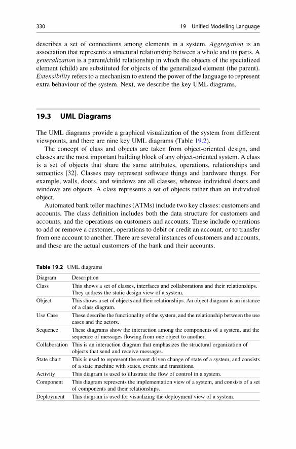
describes a set of connections among elements in a system. Aggregation is an
association that represents a structural relationship between a whole and its parts. A
generalization is a parent/child relationship in which the objects of the specialized
element (child) are substituted for objects of the generalized element (the parent).
Extensibility refers to a mechanism to extend the power of the language to represent
extra behaviour of the system. Next, we describe the key UML diagrams.
19.3 UML Diagrams
The UML diagrams provide a graphical visualization of the system from different
viewpoints, and there are nine key UML diagrams (Table 19.2).
The concept of class and objects are taken from object-oriented design, and
classes are the most important building block of any object-oriented system. A class
is a set of objects that share the same attributes, operations, relationships and
semantics [32]. Classes may represent software things and hardware things. For
example, walls, doors, and windows are all classes, whereas individual doors and
windows are objects. A class represents a set of objects rather than an individual
object.
Automated bank teller machines (ATMs) include two key classes: customers and
accounts. The class definition includes both the data structure for customers and
accounts, and the operations on customers and accounts. These include operations
to add or remove a customer, operations to debit or credit an account, or to transfer
from one account to another. There are several instances of customers and accounts,
and these are the actual customers of the bank and their accounts.
Table 19.2 UML diagrams
Diagram Description
Class This shows a set of classes, interfaces and collaborations and their relationships.
They address the static design view of a system.
Object This shows a set of objects and their relationships. An object diagram is an instance
of a class diagram.
Use Case These describe the functionality of the system, and the relationship between the use
cases and the actors.
Sequence These diagrams show the interaction among the components of a system, and the
sequence of messages flowing from one object to another.
Collaboration This is an interaction diagram that emphasizes the structural organization of
objects that send and receive messages.
State chart This is used to represent the event driven change of state of a system, and consists
of a state machine with states, events and transitions.
Activity This diagram is used to illustrate the flow of control in a system.
Component This diagram represents the implementation view of a system, and consists of a set
of components and their relationships.
Deployment This diagram is used for visualizing the deployment view of a system.
330 19 Unified Modelling Language
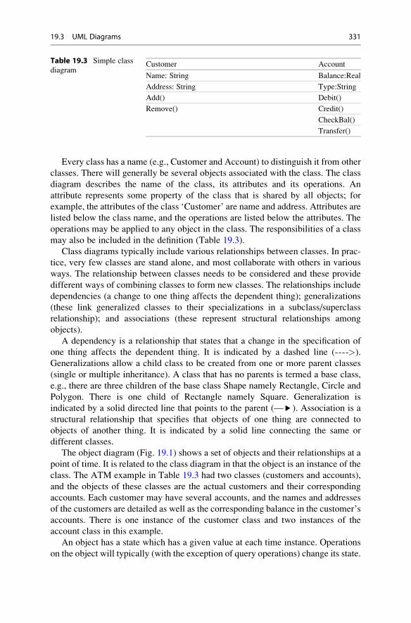
Every class has a name (e.g., Customer and Account) to distinguish it from other
classes. There will generally be several objects associated with the class. The class
diagram describes the name of the class, its attributes and its operations. An
attribute represents some property of the class that is shared by all objects; for
example, the attributes of the class ‘Customer’ are name and address. Attributes are
listed below the class name, and the operations are listed below the attributes. The
operations may be applied to any object in the class. The responsibilities of a class
may also be included in the definition (Table 19.3).
Class diagrams typically include various relationships between classes. In prac-
tice, very few classes are stand alone, and most collaborate with others in various
ways. The relationship between classes needs to be considered and these provide
different ways of combining classes to form new classes. The relationships include
dependencies (a change to one thing affects the dependent thing); generalizations
(these link generalized classes to their specializations in a subclass/superclass
relationship); and associations (these represent structural relationships among
objects).
A dependency is a relationship that states that a change in the specification of
one thing affects the dependent thing. It is indicated by a dashed line (---->).
Generalizations allow a child class to be created from one or more parent classes
(single or multiple inheritance). A class that has no parents is termed a base class,
e.g., there are three children of the base class Shape namely Rectangle, Circle and
Polygon. There is one child of Rectangle namely Square. Generalization is
indicated by a solid directed line that points to the parent (—▸). Association is a
structural relationship that specifies that objects of one thing are connected to
objects of another thing. It is indicated by a solid line connecting the same or
different classes.
The object diagram (Fig. 19.1) shows a set of objects and their relationships at a
point of time. It is related to the class diagram in that the object is an instance of the
class. The ATM example in Table 19.3 had two classes (customers and accounts),
and the objects of these classes are the actual customers and their corresponding
accounts. Each customer may have several accounts, and the names and addresses
of the customers are detailed as well as the corresponding balance in the customer’s
accounts. There is one instance of the customer class and two instances of the
account class in this example.
An object has a state which has a given value at each time instance. Operations
on the object will typically (with the exception of query operations) change its state.
Table 19.3 Simple class
diagramCustomer Account
Name: String Balance:Real
Address: String Type:String
Add() Debit()
Remove() Credit()
CheckBal()
Transfer()
19.3 UML Diagrams 331

An object diagram contains objects and links to other objects, and gives a snapshot
of the system at a particular moment of time.
A use case diagram model the dynamic aspects of the system, and it shows a set of
use cases and actors and their relationships. It describes scenarios (or sequences of
actions) in the system from the user’s viewpoint (actor), and shows how the actor
interacts with the system. An actor represents the set of roles that a user can play, and
the actor may be human or an automated system. Actors are connected to use cases by
association, and they may communicate by sending and receiving messages.
A use case diagram shows a set of use cases and each use case represents a
functional requirement. Use cases are employed to model the visible services that
the system provides within the context of its environment, and for specifying the
requirements of the system as a black box. Each use case carries out some work that
is of value to the actor, and the behaviour of the use case is described by the flow of
events in text. The description includes the main flow of events for the use case and
the exceptional flow of events. These flows may also be represented graphically.
There may also be alternate flows as well as the main flow of the use case. Each
sequence is termed a scenario and a scenario is one instance of a use case.
Use cases provide a way for the end users and developers to share a common
understanding of the system. They may be applied to all or part of the system
(subsystem), and the use cases are used as the basis for development and testing. A
use case is represented graphically by an ellipse. The benefits of use cases include:
• Enables the stakeholders (e.g., domain experts, developers, testers and end users)
to share a common understanding
• Models the requirements (specifies what the system should do).
• Models the context of a system (identifies actors and their roles)
• Used for development and testing.
Figure 19.2 presents a simple example of the definition of the use cases for an
ATM application. The typical user operations at an ATM machine include the
balance inquiry operation, cash withdrawal, and the transfer of funds from one
account to another. The actors for the system include ‘customer’ and ‘admin’, and
these actors have different needs and expectations of the system.
The behaviour from the user’s viewpoint is described, and the use-cases include
“withdraw cash”, “balance enquiry”, “transfer” and “maintain/reports”. The use
case view of the system includes the actors who are performing the sequence of
actions.
Customer (J.Bloggs)
Name = “J.Bloggs”Address= “Mallow”
Account (J.Bloggs personal account)Balance=1,000Type= “Saving”
Balance=500Type= “Current”
Account (J.Bloggs personal account)
Fig. 19.1 Simple object
diagram
332 19 Unified Modelling Language

The next UML diagram considered is the sequence diagram which models the
dynamic aspects of the system, and shows the interaction between objects/classes in
the system for each use case. The interactions model the flow of control that
characterises the behaviour of the system, and the objects that play a role in the
interaction are identified. A sequence diagram emphasizes the time ordering of
messages, and the interactions may include messages that are dispatched from
object to object, with the messages ordered in sequence by time. The example in
Fig. 19.4 considers the sequences of interactions between objects for the “Balance
Enquiry” use case. This sequence diagram is specific to the case of a valid balance
enquiry, and a sequence diagram is needed to handle the exception cases as well
(Fig. 19.3).
Fig. 19.2 Use-Case diagram
of ATM machine
Fig. 19.3 UML sequence diagram
19.3 UML Diagrams 333

The behaviour of the “balance enquiry” operation is evident from the diagram.
The customer inserts the card into the ATM machine and the PIN number is
requested by the ATM. The customer then enters the number and the ATMmachine
contacts the bank for verification of the number. The bank confirms the validity of
the number and the customer then selects the balance enquiry operation. The ATM
contacts the bank to request the balance of the particular account, and the bank
sends the details to the ATMmachine. The balance is displayed on the screen of the
ATM machine. The customer then withdraws the card. The actual sequence of
interactions is evident from the sequence diagram.
The example in Fig. 19.3 has four objects (Customer, ATM, Bank and Account)
and these are laid out from left to right at the top of the sequence diagram.
Collaboration diagrams are interaction diagrams that consist of objects and their
relationships. However, while sequence diagrams emphasize the time ordering of
messages, a collaboration diagram emphasizes the structural organization of the
objects that send and receive messages. Sequence diagrams and collaboration
diagrams may be converted to the other without loss of information. Collaboration
diagrams are described in more detail in [32].
The activity diagram is considered in Fig. 19.4, and this is essentially a flow
chart showing the flow of control from one activity to another. It is used to model
the dynamic aspects of a system, and this involves modelling the sequential and
possibly concurrent steps in a computational process. It is different from a sequence
diagram in that it shows the flow from activity to activity, whereas a sequence
diagram shows the flow from object to object.
Fig. 19.4 UML activity
diagram
334 19 Unified Modelling Language

State diagrams or state charts show the dynamic behaviour of a class, and how
different operations result in a change of state. There is an initial state and a final
state, and the operations result in different states being entered and exited. There
are several other UML diagrams including component and deployment diagrams.
The reader is referred to [32].
19.3.1 Advantages of UML
UML offers a rich notation to model software systems and to understand the
proposed system from different viewpoints. The main advantages of UML are
given in Table 19.4.
19.4 Rational Unified Process
Software projects need a well-structured development process to achieve their
objectives. The Rational Unified Development Software Process (RUP) [57] has
become important in recent years, and RUP and UML are often used together. It is
• Use case driven
• Architecture centric
• Iterative and incremental
It includes iterations, phases, workflows, risk mitigation, quality control, project
management, and configuration control. Software projects may be complex, and
there are risks that requirements may be missed in the process, or that the interpre-
tation of a requirement may differ between the customer and developer. RUP
gathers requirements as use cases, which describe the functional requirements
from the point of view of the users of the system.
The use case model describes what the system will do at a high-level, and there is
user focus in defining the scope the project. Use cases drive the development
Table 19.4 Advantages of UML
Advantages of UML
Visual modelling language with a rich expressive notation.
Mechanism to manage complexity of a large system
Enables the proposed system to be studied before implementation.
Visualization of architecture design of the system.
The UML diagrams provide different views of the system.
Visualization of system from different viewpoints.
Use cases allow the description of typical user behaviour.
Better understanding of implications of user behaviour.
Use cases provide a mechanism to communicate the proposed behaviour of the software system
Use cases are the basis of development and testing.
19.4 Rational Unified Process 335

process, and the developers create a series of design and implementation models
that realize the use cases. The developers review each successive model for
conformance to the use-case model. The testers verify that the implementation
model correctly implements the use cases.
The software architecture concept embodies the most significant static and
dynamic aspects of the system. The architecture grows out of the use cases and
factors such as the platform that the software is to run on, deployment
considerations, legacy systems, and non-functional requirements.
A commercial software product is a large undertaking and the work is
decomposed into smaller slices or mini-projects, where each mini-project is a
manageable chunk. Each mini-project is an iteration that results in an increment
(Fig. 19.5).
Iterations refer to the steps in the workflow, and an increment leads to the growth
of the product. If the developers need to repeat the iteration, the organization loses
only the misdirected effort of a single iteration, rather than the entire product.
Therefore, the unified process is a way to reduce risk in software engineering.
Rup consists of four phases, and these are inception, elaboration, construction
and transition. Each phase consists of one or more iterations, and the iteration
consists of several workflows. The workflows may be requirements, analysis,
design, implementation and test. Each phase terminates in a milestone with one
or more project deliverables (Fig. 19.6).
The inception identifies and prioritizes the most important risks, and it is
concerned with initial project planning, cost estimation and early work on the
architecture and functional requirements for the product. The elaboration phase
specifies most of the use cases in detail. The construction phase is concerned with
building the product, and implements all agreed use cases. The transition phase
covers the period during which the product moves into the customer site and
includes activities such as training customer personnel, providing help-line assis-
tance and correcting defects found after delivery.
Fig. 19.5 Rational unified process
336 19 Unified Modelling Language

The waterfall lifecycle has the disadvantage that the risk is greater towards the
end of the project, where it is costly to undo mistakes from earlier phases. Iterative
processes were developed as a response to this, with the waterfall steps applied
in the iteration. Instead of developing the whole system in one step, an increment
(i.e., a subset of the system functionality) is selected and developed, then another
increment, and so on.
19.5 Review Questions
1. What is UML? Explain its main features.
2. Explain the difference between an object and a class.
3. Describe the various UML diagrams.
4. What are the advantages and disadvantages of UML?
5. What is the Rational Unified Process?
6. Describe the workflows in a typical iteration.
7. Describe the phases in the Rational Unified Process.
19.6 Summary
The unified modelling language is a visual modelling language for software
systems, and it facilitates the understanding of the architecture, and management
of the complexity of large systems. It was developed as a notation for modelling
Fig. 19.6 Phases and workflows in rational unified process
19.6 Summary 337

object-oriented systems, and it provides a visual means of specifying, constructing
and documenting the object-oriented system.
UML is applied to formally model the system and it allows the same information
to be presented in many different ways and at different levels of detail. The
requirements of the system are expressed in use cases; and other views include
the design view which captures the problem space and solution space; the process
view which models the systems processes; the implementation view and the
deployment view. There are nine main diagrams providing different viewpoints
of the system, and these provide the blueprint of the software.
RUP consists of four phases, and these are inception, elaboration, construction
and transition. Each phase consists of one or more iterations, and the iteration
consists of several workflows. The workflows may be requirements, analysis,
design, implementation and test. Each phase terminates in a milestone with one
or more project deliverables.
338 19 Unified Modelling Language

Epilogue 20
We embarked on a long journey is this book and set ourselves the objective of
providing an introduction to the software quality field to students and practitioners.
The book was based on the author’s experience in software quality and software
process improvement at leading industrial companies. The principles of software
quality management and software process improvement were discussed.
The goal was to cover both theory and practice, and to give the reader a grasp of
the fundamentals of the software quality field, as well as guidance on how to apply
the theory in an industrial environment.
We noted that companies today need to focus on customer satisfaction and software
quality, and need to ensure that the desired quality is built into the software product.
Customers today have very high expectations on quality, and expect high-quality
software products to be consistently delivered on time. The focus on quality requires
that the organization define a sound software development infrastructure to enable
quality software to be consistently produced.
Quality improvement also requires that the organization be actively aware of
industrial best practice, as well as emerging technologies from various research
programs. Piloting or technology transfer of innovative technology is an important
part of continuous improvement.
We started our journey with a discussion of some key figures in the history of
quality including well-known quality gurus such as Shewhart, Deming, Juran, and
Crosby. These grandfathers of quality played an important role in promoting quality
in business, and in helping companies to change and to be more effective in
delivering high-quality products. We also discussed the contributions of Watts
Humphrey, who is considered the father of software quality.
We described approaches used in current software engineering to build quality into
software. We discussed project planning and tracking, software lifecycles, software
inspections and testing, configuration management, software quality assurance, etc.
The capability maturity model integrated (CMMI) was discussed and it provides a
framework that assists organizations in software process improvement. It allows them
to assess the current capability or maturity of selected software processes and to
prioritize improvements.
G. O’Regan, Introduction to Software Quality, Undergraduate Topicsin Computer Science, DOI 10.1007/978-3-319-06106-1_20,# Springer International Publishing Switzerland 2014
339
The assessment (or SCAMPI appraisal) of an organization against the CMMI
reveals strengths and weaknesses of the management and engineering processes in
the organization. The output from the appraisal is used to formulate an improvement
plan, which is then tracked to completion. The execution of the plan may take 1 or
more years of effort.
We provided an introduction to project management and discussed project
estimation, project planning and scheduling, project monitoring and control, risk
management, and managing project quality.
We then discussed requirements and design, and discussed requirements elicitation,
software design, and implementation. We then moved on to discuss the configuration
management, and the concept of a baseline. Configuration management is concerned
with identifying those deliverables that are subject to change control, and controlling
changes to them.
We then discussed software inspections including Fagan inspections, as well as
the less formal review and walkthrough methodologies. Software testing was then
discussed, including the various types of testing that may be carried out, and we
discussed test planning, test case definition, test tracking, test metrics, test
reporting, and testing in an e-commerce environment.
We then discussed the selection and management of a software supplier, and
described how candidate suppliers may be formally evaluated, and how the selected
supplier may be managed during the project.
We then discussed software quality assurance and the importance of process
quality. This chapter explained audits and described how they are carried out. We
then discussed metrics and problem solving, including the balanced score card and
GQM. We presented a collection of sample metrics for an organization.
We then discussed the ISO 9000 standard, which is an important standard for
product and service delivery. The main features of the standard were discussed as
well as guidance on its implementation.
We then discussed the important field of software process improvement. It began
with a discussion of a software process, and discussed the benefits that may be
gained from software process improvement.
We then gave an overview of the CMMI model, and discussed its five maturity
levels and their constituent process areas. We discussed both the staged and
continuous representations.
We then discussed the activities and teams required to set up a CMMI improve-
ment initiative for an organization. These include the CMMI Steering Group, the
SEPG team and process specific teams.
We then discussed the SCAMPI appraisal methodology, and this included a
discussion of the formal SCAMPI Class A appraisal used large organizations to
obtain a CMMI rating, as well as the less formal SCAMPI Class B and C appraisals.
We then examined various tools to support the organizations in improving their
software engineering maturity. The focus is first to define the process, and then to
find tools to support the process.
We then discussed formal methods which are often employed in the safety
critical and security critical fields. These consist of a set of mathematical techniques
340 20 Epilogue

to specify and derive a program from its specification. Formal methods may be
employed to rigorously state the requirements of the proposed system; they may
be employed to derive a program from its mathematical specification; and they
provide a rigorous proof that the implemented program satisfies its specification.
We then presented the Z specification language, which is one of the most widely
used formal methods. It was developed at Oxford University in the U.K.
Finally, we presented the unified modelling language (UML) which presents
various views of the system architecture. Finally, we consider the future of software
quality.
20.1 The Future of Software Quality
Quality will continue to be fundamental to the success of the company. There is
likely to be an increased focus on achieving approved quality systems such as ISO
9001, or to achieve a specific CMMI maturity level. Many companies are ISO 9001
certified or are working towards certification, or have been assessed to be
performing at a particular CMMI maturity level. Customer expectations are
increasing all the time, and in the future it is likely that software companies will
need to have a minimal quality standard such as ISO 9001 or CMM level 3 to be
taken seriously by potential customers.
The cost of poor quality is currently measured in mature companies. It is likely
to be measured in many more software companies in the future, as driving down the
cost of poor quality will become a key goal for many organizations to improve their
profitability and long-term survival.
Software components and the verification of software components may become
increasingly important, as companies will wish to speed up development to shorten
the time to market, which is a key driver in today’s competitive environment.
However, software organizations will need to have confidence in the correctness
of the components, and there may be an independent certification body to verify
that components are correct.
20.1 The Future of Software Quality 341

Glossary
ADS Appraisal Disclosure Statement
AMN Abstract Machine Notation
AQL Acceptable Quality Level
ATM Automated Teller Machine
BRS Business Requirements Specification
BSC Balanced Score Card
CAR Causal Analysis and Resolution
CCB Change Control Board
CCS Calculus Communicating Systems
CICS Customer Information Control System
CM Configuration Management
CMM® Capability Maturity Model
CMMI® Capability Maturity Model Integration
COCOMO Constructive Cost Model
COPQ Cost of Poor Quality
COTS Customized Off the Shelf
CSP Communicating Sequential Processes
DAR Decision Analysis and Resolution
DMAIC Define, Measure, Analyse, Improve, Control
DMADV Define, Measure, Analyse, Design, Verify
DOORS Dynamic Object-Oriented Requirements System
DSDM Dynamic Systems Development Method
EAF Effort Adjustment Factor
ESA European Space Agency
ESI European Software Institute
FAR Functional Area Representatives
FI Fully Implemented
FMEA Failure Mode and Effects Analysis
FSM Finite State Machine
GG Generic Goal
GP Generic Practice
GQM Goal, Question, Metric
GUI Graphical User Interface
HP Hewlett Packard
G. O’Regan, Introduction to Software Quality, Undergraduate Topicsin Computer Science, DOI 10.1007/978-3-319-06106-1,# Springer International Publishing Switzerland 2014
343
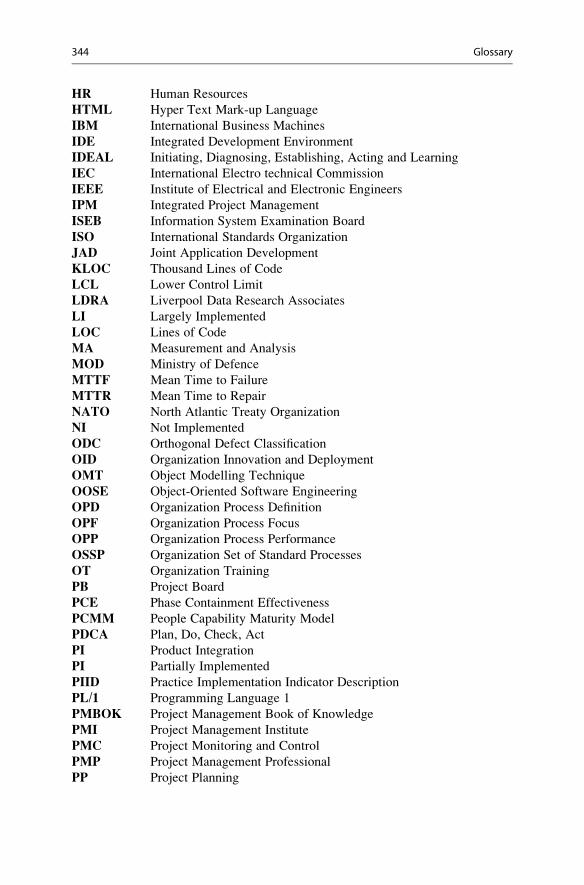
HR Human Resources
HTML Hyper Text Mark-up Language
IBM International Business Machines
IDE Integrated Development Environment
IDEAL Initiating, Diagnosing, Establishing, Acting and Learning
IEC International Electro technical Commission
IEEE Institute of Electrical and Electronic Engineers
IPM Integrated Project Management
ISEB Information System Examination Board
ISO International Standards Organization
JAD Joint Application Development
KLOC Thousand Lines of Code
LCL Lower Control Limit
LDRA Liverpool Data Research Associates
LI Largely Implemented
LOC Lines of Code
MA Measurement and Analysis
MOD Ministry of Defence
MTTF Mean Time to Failure
MTTR Mean Time to Repair
NATO North Atlantic Treaty Organization
NI Not Implemented
ODC Orthogonal Defect Classification
OID Organization Innovation and Deployment
OMT Object Modelling Technique
OOSE Object-Oriented Software Engineering
OPD Organization Process Definition
OPF Organization Process Focus
OPP Organization Process Performance
OSSP Organization Set of Standard Processes
OT Organization Training
PB Project Board
PCE Phase Containment Effectiveness
PCMM People Capability Maturity Model
PDCA Plan, Do, Check, Act
PI Product Integration
PI Partially Implemented
PIID Practice Implementation Indicator Description
PL/1 Programming Language 1
PMBOK Project Management Book of Knowledge
PMI Project Management Institute
PMC Project Monitoring and Control
PMP Project Management Professional
PP Project Planning
344 Glossary

PPM Project Portfolio Management
PPQA Process and Product Quality Assurance
Prince Projects In a Controlled Environment
PSP Personal Software Process
PVCS Polytron Version Control System
QA Quality Assurance
QCC Quality Control Circle
QMS Quality Management System
QPM Quantitative Project Management
RAD Rapid Application Development
RAG Red, Amber, Green
RCA Root Cause Analysis
RD Requirements Development
RFP Request for Proposal
RM Requirements Management
ROI Return on Investment
RPM Rational Portfolio Manager
RSM Rational Software Modeller
RSKM Risk Management
RUP Rational Unified Process
SAM Supplier Agreement Management
SCAMPI Standard CMMI Appraisal Method for Process Improvement
SEI Software Engineering Institute
SEPG Software Engineering Process Group
SG Specific Goal
SLA Service Level Agreement
SLOC Source lines of code
SOW Statement of Work
SP Specific Practice
SPC Statistical Process Control
SPI Software Process Improvement
SPICE Software Process Improvement Capability dEtermination
SQA Software Quality Assurance
SSADM Structured Systems Analysis and Design Method
TQM Total Quality Management
TS Technical Solution
TSP Team Software Process
UAT User Acceptance Testing
UCL Upper Control Limit
UK United Kingdom
UML Unified Modelling Language
VAL Validation
VDM Vienna Development Method
VDM♣ Irish School of VDM
Glossary 345

VER Verification
VOB Version Object Base
VSS Visual Source Safe
Y2K Year 2000
346 Glossary

References
1. Appraisal Requirements for CMMI V1.2. (ARC V1.2) (2006) SCAMPI Upgrade Team.
TR CMU/SEI-2006-TR-011. August, 2006
2. Basili V, Rombach H (1988) The TAME project. Towards improvement-oriented software
environments. IEEE Trans Softw Eng 14(6):758–773
3. Beck K (2000) Extreme Programming explained. Embrace change. Addison-Wesley, Reading
4. Bhandari I (1993) A case study of software process improvement during development. IEEE
Trans Softw Eng 19(12):1157–1170
5. Bjorner D, Cliff J (1978) The Vienna development method. The meta language, vol 61, Lecture
notes in computer science. Springer, New York
6. Bjorner D, Jones C (1982) Formal specification and software development, Prentice Hall
International series in computer science. Prentice Hall International, Englewood Cliffs
7. Boehm B (1981) Software engineering economics. Prentice Hall, Englewood Cliffs
8. Boehm B (1988) A spiral model for software development and enhancement. Computer
21:61–72
9. Brassard M, Ritter D (1994) The Memory Jogger. A pocket guide of tools for continuous
improvement and effective planning. Goal/QPC, Methuen
10. Brooks F (1975) The mythical man month. Addison Wesley, Reading
11. Brooks F (1986) No silver bullet. Essence and accidents of software engineering. In: Information
processing. Elsevier, Amsterdam
12. Buxton JN, Naur P, Randell B (1975) Software Engineering. Petrocelli. Report on two NATO
conferences held in Garmisch, Germany (October1968) and Rome, Italy (October 1969)
13. Chrissis MB, Conrad M, Shrum S (2011) CMMI for development. Guidelines for process
integration and product improvement, 3rd edn, SEI series in software engineering. Addison
Wesley, Boston
14. Crosby P (1979) Quality is free. The art of making quality certain. McGraw Hill, New York
15. Deming WE (1986) Out of crisis. MIT Press, Cambridge, MA
16. Dijkstra EW (1972) Structured programming. Academic, London
17. Dijkstra EW (1976) A disciple of programming. Prentice Hall, Englewood Cliffs
18. Diller A (1990) Z. An introduction to formal methods. Wiley, England
19. Dunaway DK, Masters S (1996) CMM Based Appraisal for Internal Process Improvement
(CBA IPI): method description. Technical report CMU/SEI-96-TR-007. Software Engineering
Institute, Pittsburgh
20. Fagan M (1976) Design and code inspections to reduce errors in software development.
IBM Syst J 15(3):182–210
21. Fenton N (1995) Software metrics: A rigorous approach. Thompson Computer Press, Boston
22. Gerhart S, Craighen D, Ralston T (1994) Experience with formal methods in critical systems.
IEEE Software, January 1994
23. Gilb T (1976) Software metrics. Winthrop Publishers, Inc., Cambridge
24. Gilb T, Graham D (1994) Software inspections. Addison-Wesley, Reading
25. Gries D (1981) The science of programming. Springer, Berlin
G. O’Regan, Introduction to Software Quality, Undergraduate Topicsin Computer Science, DOI 10.1007/978-3-319-06106-1,# Springer International Publishing Switzerland 2014
347

26. Hinchey M, Bowen J (eds) (1995) Applications of formal methods, Prentice Hall International
series in computer science. Prentice Hall, New York
27. Hoare CAR (1985) Communicating sequential processes, Prentice Hall International series in
computer science. Prentice Hall International, Englewood Cliffs
28. Hoare JP (1995) Application of the B-method to CICS. In: Hinchey M, Bowen JP (eds)
Applications of formal methods, Prentice Hall International series in computer science.
Prentice Hall, New York
29. Humphry W (1989) Managing the software process. Addison-Wesley, Reading
30. Ince D, Andrews D (1991) Practical formal methods with VDM, McGraw Hill International
series in software engineering. McGraw Hill, New York
31. ISO/IEC (1991) ISO/IEC 9126: Information Technology. Software Product Evaluation:
quality characteristics and guidelines for their use. ISO/IEC, Geneva
32. Jacobson I, Booch G, Rumbaugh J (1999) The unified software modelling language user guide.
Addison-Wesley, Reading
33. Juran J (1951) Juran’s quality handbook. McGraw Hill, New York
34. Kaplan RS, Norton DP (1996) The balanced scorecard. Translating strategy into action.
Harvard Business School Press, Boston
35. Keeni G et al (2000) The evolution of quality processes at Tate Consultancy Services. IEEE
Software 17(4):79–88
36. Kuhn T (1970) The structure of scientific revolutions. University of Chicago Press, Chicago
37. Lakatos I (1976) Proof and refutations. The logic of mathematical discovery. Cambridge
University Press, Cambridge
38. Lions JL (1996) Ariane 5. Flight 501. Failure report by enquiry board, The MathWorks, Inc.,
Natick
39. Mac An Airchinnigh M (1990) Conceptual models and computing. PhD thesis, Department of
Computer Science, University of Dublin. Trinity College, Dublin
40. Manley E (1995) Taurus: how I lived to tell the tale. Am Program Softw Fail 8:17
41. Manns T, Coleman M (1996) Software quality assurance. Macmillan Press Ltd., Hampshire
42. McDonnell E (1994) The development of a multiplex bundling system using formal methods,
vols I & II. MSc thesis. Department of Computer Science, Trinity College, Dublin
43. Milner R et al (1989) A calculus of mobile processes (Part 1). LFCS report series. ECS-LFCS-
89-85. Department of Computer Science. University of Edinburgh, Edinburgh
44. Ministry of Defence (1991) 00-55 (PART 1)/Issue 1, The procurement of safety critical
software in defence equipment, PART 1: Requirements. Ministry of Defence, Interim Defence
Standard, UK
45. Ministry of Defence (1991) 00-55 (PART 2)/Issue 1, The procurement of safety critical
software in defence equipment, PART 2: Guidance. Ministry of Defence, Interim Defence
Standard, UK
46. O’Hara F (1998) Peer reviews – the key to cost effective quality. European SEPG, Amsterdam
47. O’Regan G (2002) A practical approach to software quality. Springer, New York
48. O’Regan G (2006) Mathematical approaches to software quality. Springer, London
49. O’Regan G (2010) Introduction to software process improvement. Springer, London
50. O’Regan G (2013) Mathematics in computing. Springer, London
51. Office of Government Commerce (2004) Managing successful projects with PRINCE2. TSO,
London
52. Parnas D (1972) On the criteria to be used in decomposing systems into modules. Commun
ACM 15(12):1053–1058
53. Peterson B (1995) The IDEAL model. Software Engineering Institute. Software process
improvement and practice (Pilot Issue), Wiley, New York, August. 1995
54. Polya G (1957) How to solve it. A new aspect of mathematical method. Princeton University
Press, Princeton
55. Rational for the development of the U.K. defence standards for safety critical software.
COMPASS conference, June 1990. Ministry of Defence
348 References

56. Royce W (1970) The software lifecycle model (Waterfall Model). In: Proceedings of the
WESTCON, Los Angeles, August, 1970
57. Rumbaugh J et al (1999) The unified software development process. Addison-Wesley,
Reading
58. Shewhart W (1931) The economic control of manufactured products. Van Nostrand,
New York
59. Software Engineering Institute (2006) CMMI executive overview. Presentation by the SEI.
Software Engineering Institute
60. Software Engineering Institute (2009) CMMI impact. Presentation by Anita Carleton. Soft-
ware Engineering Institute. August 2009
61. Sommerville I (2011) Software engineering, 9th edn. Pearson, Boston
62. Spivey JM (1992) The Z notation. A reference manual, Prentice Hall International series in
computer science. Prentice Hall, Englewood Cliffs
63. Standard CMMI Appraisal Method for Process Improvement (2006) CMU/SEI-2006-HB-002.
V1.2. August 2006
64. Standish Group (1999) Estimating: art or science. Featuring Morotz Cost Expert. Standish
Group Research Note
65. Tierney M (1991) The evolution of Def Stan 00-55 and 00-56: an intensification of the “Formal
Methods debate” in the UK. Research Centre for Social Sciences, University of Edinburgh,
Edinburgh
66. Wichmann BA (2000) A personal view of formal methods. National Physical Laboratory,
March 2000
References 349

Index
A
Agile development, 46–47
Analogy method, 63
Appraisals, 29
plan, 257–258
Ariane 5, 4
Ariane-5 disaster, 41
Audit escalation, 149
Audit meeting, 147–148
Audit planning, 146
Audit reporting, 148
Axiomatic approach, 296
B
Balanced scorecard (BSC), 154–156
Baldridge, Malcom, 53
Barriers to success, 207–208
Baseline, 90
Basili, Victor, 26, 152
Booch method, 327
Breakthrough and control, 12
Brooks, Fred, 5
BSC. See Balanced scorecard (BSC)
Business case, 61
C
Calculus communicating systems (CCS), 303
Capability maturity model integration
(CMMI), 35–57, 101–134, 211–232
appraisals, 243–244
categories of, 222
kick-off session, 245–246
maturity levels, 217–220
process areas, 222–223
project manager, 236, 242
project plan, 244–245
project schedule, 245
representations, 220–222
CCB. See Change controlboard (CCB)
CCS. See Calculus communicating
systems (CCS)
Change control, 95–97
Change control board (CCB), 71, 82
Change request, 71
CICS. See Customer Information Control
System (CICS)
Clarity PPM, 274
Class diagrams, 331
Clearcase, 92
Clearquest, 92
CMMI. See Capability maturity model
integration (CMMI)
COCOMO. See Constructive Cost Model
(COCOMO)
Communicating sequential processes
(CSP), 303
Commuting diagram property, 323
Conducting the appraisal, 261–267
Configuration control, 91
Configuration identification, 91
Configuration management, 89
audits, 98
plan, 95
Constructive Cost Model
(COCOMO), 272
Continuous improvement cycle, 236
Continuous representation, 220
Cost of poor quality (COPQ), 24, 103
Cost predictor models, 63
Crosby, Philip, 5, 15
CSP. See Communicating sequential
processes (CSP)
Customer care metrics, 168–170
Customer Information Control System
(CICS), 293
Customer satisfaction, 26–27
metrics, 157–158
G. O’Regan, Introduction to Software Quality, Undergraduate Topicsin Computer Science, DOI 10.1007/978-3-319-06106-1,# Springer International Publishing Switzerland 2014
351

D
Darlington Nuclear power plant, 293
Data reification, 323
Dedicated improvement sub-teams, 241–242
Def Stan 00-55, 292
Deliver appraisal results, 267
Deming, W. Edwards, 10
Development quality metrics, 164–167
Dynamic Object-Oriented Requirements
System (DOORS), 276
E
E-commerce testing, 131–133
Enterprise Architect, 280
ESA. See European Space Agency (ESA)
Escrow agreement, 139
Estimation, 62
European Space Agency (ESA), 41
Expert judgment, 63
F
Fagan inspections, 38, 53, 108–116
guidelines, 109
Fagan, Michael, 20
Fishbone diagrams, 23, 175–177
Formal methods, 55–56
Formal specification, 289
Functional requirement, 78
Function points, 63
G
Generate appraisal results, 266–267
Generic goals, 226
Generic practices, 226
Gilb, Tom, 26
Goal Question Metric (GQM), 26, 152
H
Histograms, 23, 177–178
Human Resources and Training Metrics,
160–162
Humphrey, Watts, 17, 212
I
IDE. See Integrated development
environment (IDE)
IEEE standards, 43
Information hiding, 84, 305
Inspection meeting, 112
Integrated development environment
(IDE), 280
Irish School of VDM (VDM♣), 300
ISO 9000, 185
ISO 9001, 187, 205
implementation, 195
ISO 9004, 187
ISO 9126, 5
ISO 9000 Certification Process, 195–197
J
Juran, Joseph, 12
L
LDRA Tools, 117, 283
M
Maintenance, 52
Mathematical proof, 297, 324
Measurement, 151
Microsoft Project, 273
Model, 43
Model-oriented approach, 294
Mongolian Hordes Approach, 35
N
Non-functional requirements, 78
O
Object diagram, 331
Object Modelling Technique (OMT), 327
Object-Oriented Software Engineering
(OOSE), 327
OMT. SeeObject Modelling Technique (OMT)
OOSE. See Object-Oriented Software
Engineering (OOSE)
P
Pareto chart, 23, 178–179
Parnas, 39, 49, 86, 305
Partial correctness, 303
Partial function, 316
PCE. See Phase containment
effectiveness (PCE)
Performance testing, 51
Personal Software Process (PSP), 205
352 Index

Phase containment effectiveness (PCE), 115
PIIDs. See Practice Implementation Indicator
Descriptions (PIIDs)
Piloting the process, 249
Planview, 274
Planview Enterprise, 274
PMBOK. See Project management
body of knowledge (PMBOK)
Polytron Version Control System (PVCS),
92, 282
Postcondition, 301
Practice Implementation Indicator
Descriptions (PIIDs), 256
Precondition, 301, 302
Predicate transformer, 303
Prepare participants, 261–262
Prince 2, 38, 53, 61, 74
Problem-solving techniques, 174–182
Process calculi, 303
Process improvement metrics, 158–160
Process mapping, 206, 246–248
Process maturity models, 54–55
Process model, 204
Professional Engineering Association, 36
Professional engineers, 40
Project, 59
Project board, 61, 72
Project closure, 73–74
Project management, 53–54, 59
metrics, 162–164
Project management body of knowledge
(PMBOK), 61
Project manager, 61
Project monitoring and control, 70–71
Project reporting, 73
Prototyping, 48, 78
PSP. See Personal Software Process (PSP)PVCS. See Polytron Version Control
System (PVCS)
Q
Quality audit metrics, 167–168
Quality center, 28, 130
Quality management (system), 69–70,
187–189
R
Rational software modeler, 278
Rational unified process, 43, 45, 336
Refinement, 290
Reporting the results, 267–268
Request for proposal (RFP), 137
Requirements, 78
analysis, 81
elicitation, 79–81
engineering, 78–79
validation, 81, 290
verification, 82
traceability, 82
RequisitePro, 277
RFP. See Request for proposal (RFP)Risk management, 67–70
Rolling out process, 249
S
SCAMPI
appraisals, 229–230, 253–269
methodology, 229
Scatter graphs, 180–181
Schema, 311
calculus, 301, 311
composition, 320–322
inclusion, 320
Scientific revolutions, 294
SEI. See Software Engineering Institute (SEI)
SEPG team, 236, 237, 240–242, 248, 249, 340
Sequence diagram, 333, 334
Shewhart model, 8
Shewhart, Walter, 8, 202
Six Sigma (6σ), 53, 206Software crisis, 36, 56
Software design, 77
Software engineering, 36, 38, 40
Software Engineering Institute (SEI), 203
Software Engineering Tools, 271–287
Software failures, 41
Software inspections, 101
Software metrics, 151–183
Software process, 200–202
improvement, 25, 199–209
Software quality assurance, 143–150
Software reuse, 50
Software testing, 50
SOW. See Statement of work (SOW)
SPC. See Statistical process control (SPC)Specific goals, 223
Specific practices, 225
Spiral model, 44
Sprint planning, 47
Standish group, 2, 36, 56
State diagrams, 335
Statement of work (SOW), 139
Statistical process control (SPC), 8
Index 353

Steering group, 236, 238, 240–242,
246, 250, 340
Story, 46
Structured walkthrough, 104
Supplier selection, 135
System testing, 51
T
Tacoma Narrows bridge, 4
Taurus project, 3
Team Software Process (TSP), 206
Test cases, 123
design, 126–127
Test director, 284
Test driven development, 51
Test environment, 121
Testing, 119
Test planning, 121, 125–126
Test process, 121–125
Test reporting, 127–128
Test tools, 124, 130–131
Total quality management (TQM), 6
Traceability, 49, 147, 277
Trend graph, 23
TSP. See Team Software Process (TSP)
U
UAT testing, 51
UML. See Unified modelling language (UML)
UML activity diagram, 334
UML diagrams, 330–335
Unified modelling language (UML),
327, 337
Unit testing, 50
Use-case diagram, 333
User requirements, 77
V
Vienna Development Method (VDM),
291, 298
VIPER, 297
Visual Source Safe (VSS), 92, 282
W
Waterfall model, 43
Weakest precondition, 303
Work breakdown structure, 63
Y
Y2K, 37, 41
Y2K bug, 4, 41
Z
Z, 291
Zermelo set theory, 302
Z specifications, 301, 312
language, 301
354 Index