georgia tech russell s. peak - georgia institute of...
TRANSCRIPT
Guest Lectures for ME 6754 - Spring 2000
Russell S. PeakGeorgia TechEngineering Information Systems Labeislab.gatech.edu
March 14/16, 2000Copyright (C) 2000 Georgia Tech

2Engineering Information Systems Lab ♦ eislab.gatech.edu© GIT
� Analysis Integration Challenges� Introduction to Constrained Objects (COBs)� Overview of COB-based XAI� Example Applications
� Electronic Packaging Thermomechanical Analysis� Aerospace Structural Analysis
� Summary

3Engineering Information Systems Lab ♦ eislab.gatech.edu© GIT
Environments,Mfg. CAD/CAM,Measurements,
etc.
Conditions
Analysis Results
Ansys
Abaqus
CAE
ImprovedDesign / Process
SelectedAnalysis Module (CBAM)
AutomatedIdealization/
Defeaturization
MCAD
ECAD
DesignProduct Model
CBAM= context-based analysis model
• Highly automated• Reusable, modular, extensible• Product-specific• Leveraging generic solvers
Analysis Results
Ansys
Abaqus
CAE
IterativeImprovements
Analysis Module Catalogs
Analysis Results
Ansys
Abaqus
CAE

4Engineering Information Systems Lab ♦ eislab.gatech.edu© GIT
(X=Design, Mfg., etc.)� Goal:
Improve product engineering processes by integrating analysismodels with other life cycle models
� Challenges:– Heterogeneous Transformations– Diversity: Information, Behaviors, Disciplines, Fidelity,
Feature Levels, CAD/CAE Tools, etc.– Multidirectional Associativity:
Design↔Analysis, Analysis ↔ Analysis� One Approach:
The Multi-Representation Architecture (MRA)� Initial Focus:
Automation of routine analysis for design
5Engineering Information Systems Lab ♦ eislab.gatech.edu© GIT
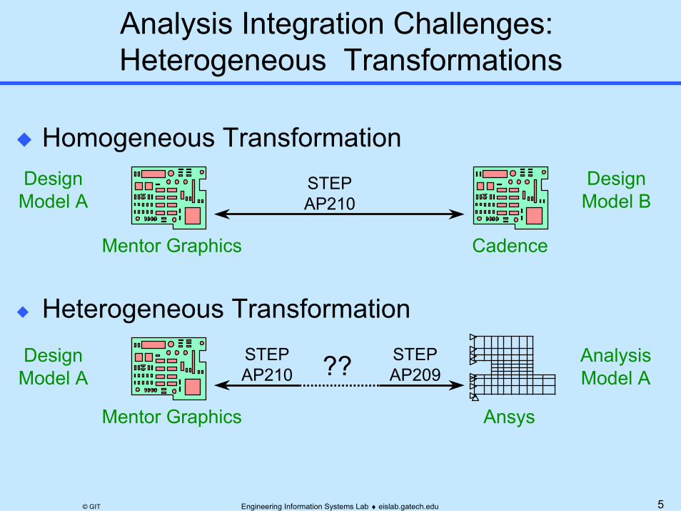
Analysis Integration Challenges: Heterogeneous Transformations
� Heterogeneous Transformation
� Homogeneous Transformation
Mentor Graphics Cadence
STEPAP210
Mentor Graphics Ansys
STEPAP210
STEPAP209??
DesignModel A
DesignModel B
DesignModel A
AnalysisModel A
6Engineering Information Systems Lab ♦ eislab.gatech.edu© GIT
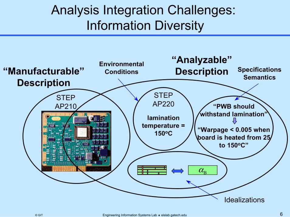
Analysis Integration Challenges: Information Diversity
EnvironmentalConditions Specifications
Semantics
Idealizations
“Manufacturable”Description
“Analyzable”Description
“PWB shouldwithstand lamination”
“Warpage < 0.005 whenboard is heated from 25
to 150oC”
laminationtemperature =
150oC
αB
STEPAP220
STEPAP210

7Engineering Information Systems Lab ♦ eislab.gatech.edu© GIT
Diverse Analysis Disciplines
Thermal
Thermomechanical
Fatigue
Vibration
Electromagnetic
Electrical
PWA 95145
U101
L101 T102
Q105
T101
Q104
R101
CR102
C102
C203 CR154 CR152
R163 CR151 CR101
C104
C103
R109 R110
Q101 Q102 C120
CR133
C153
C146 C147 C106
C111
C112
R230 R232 R233
R102 Q103
U107
U108
U103
U104
U109
U110
U105
U106
C123
R106 R107 R108
R111 R112 R113 R114 R115
R231
C118
x y
PWB 96510
J101
U102
∆ε
N
8Engineering Information Systems Lab ♦ eislab.gatech.edu© GIT
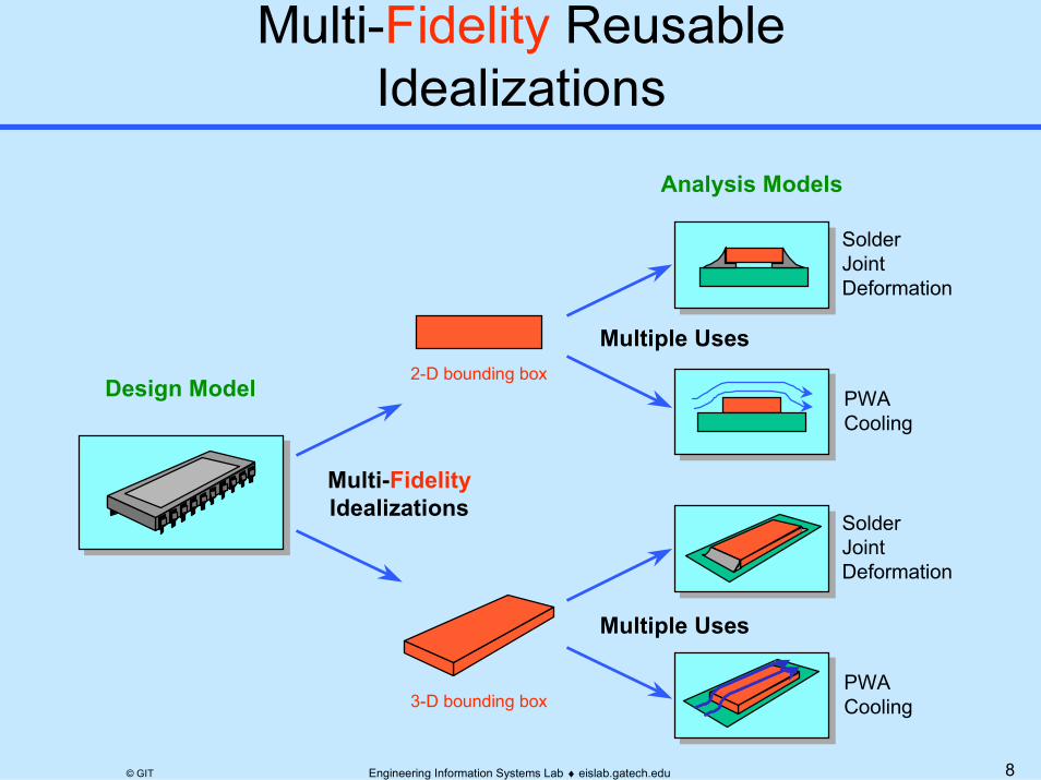
Design Model
Multi-FidelityIdealizations
2-D bounding box
3-D bounding box
Multiple Uses
SolderJointDeformation
Analysis Models
PWACooling
SolderJointDeformation
PWACooling
Multiple Uses

9Engineering Information Systems Lab ♦ eislab.gatech.edu© GIT
Same Mode; Idealized Geometries of Varying Dimension
inboard beam
Design Model (MCAD) Analysis Models (MCAE)
1D Beam/Stick Model
3D Continuum/Brick Model
flap support assembly
Mode (Behavior) = Deformation

10Engineering Information Systems Lab ♦ eislab.gatech.edu© GIT
Mode-dependent Idealized Geometries; Same DimensionThermal Resistance
Thermal Stress
FEA ModelIdealized Geometry (3D)
Common Design ModelCu(0.15)BT-Resin (0.135)
0.56
(Air)
(0.135)
Al Fin (1.5)Adhesive(0.05)
FEA ModelIdealized Geometry (3D)

11Engineering Information Systems Lab ♦ eislab.gatech.edu© GIT
Design Model (MCAD) Analysis Models (MCAE)
Part Feature Level Model
Assembly Level Model

12Engineering Information Systems Lab ♦ eislab.gatech.edu© GIT
Analysis Model(with Idealized Features)
Detailed Design Model
Channel Fitting Analysis
“It is no secret that CAD models are driving more of today’s product developmentprocesses ... With the growing number of design tools on the market, however, theinteroperability gap with downstream applications, such as finite element analysis,is a very real problem. As a result, CAD models are being recreated atunprecedented levels.” Ansys/ITI press Release, July 6 1999
http://www.ansys.com/webdocs/VisitAnsys/CorpInfo/PR/pr-060799.html
Idealizations
Γ
Missing: Explicit idealization relationsΓ1 : b = cavity3.inner_width + rib8.thickness/2
+ rib9.thickness/2
===...

13Engineering Information Systems Lab ♦ eislab.gatech.edu© GIT
CAD Modelbulkhead assembly attach point
CAE Model channel fitting analysis
materialproperties
idealizedanalysis
geometry
analysisresults
No explicitfine-grainedCAD-CAE
associativity
detaileddesigngeometry

14Engineering Information Systems Lab ♦ eislab.gatech.edu© GIT
“The Big Switch”� Sizing/synthesis during early design stages
– Input: Desired results - Ex. fatigue life, margin of safety– Output: Idealized design parameters– Outputs then used as targets to guide detailed design
� Analysis/req. checking during later design stages– Input: Detailed design parameters– Intermediate results: Idealized design parameters – Output: Analysis results - Ex. fatigue life, margin of safety– Outputs then compared with requirements
Id1=6.66
AAc=3.33 Γ=30.00
width=20
thick=0.25 P=100
I
width=20
thick=0.25
d1=7.5
Ac=3.125A
P=100
Γ=32.00
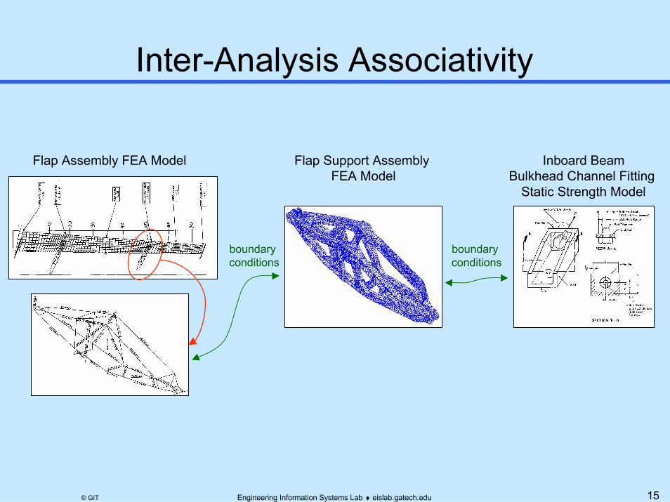
15Engineering Information Systems Lab ♦ eislab.gatech.edu© GIT
Flap Assembly FEA Model Flap Support Assembly FEA Model
Inboard BeamBulkhead Channel Fitting
Static Strength Model
boundary conditions
boundary conditions

16Engineering Information Systems Lab ♦ eislab.gatech.edu© GIT
� Analysis Integration Challenges� Introduction to Constrained Objects (COBs)� Overview of COB-based XAI� Example Applications
� Electronic Packaging Thermomechanical Analysis� Aerospace Structural Analysis
� Summary
See Part 1
17Engineering Information Systems Lab ♦ eislab.gatech.edu© GIT
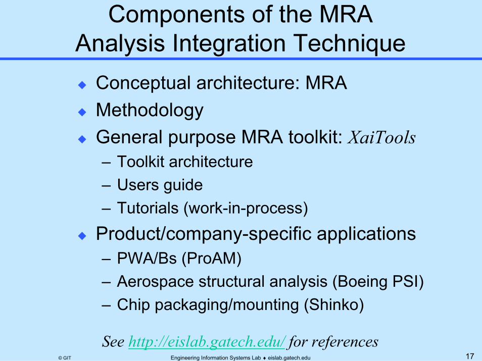
� Conceptual architecture: MRA� Methodology� General purpose MRA toolkit: XaiTools
– Toolkit architecture– Users guide– Tutorials (work-in-process)
� Product/company-specific applications– PWA/Bs (ProAM)– Aerospace structural analysis (Boeing PSI)– Chip packaging/mounting (Shinko)
See http://eislab.gatech.edu/ for references

18Engineering Information Systems Lab ♦ eislab.gatech.edu© GIT
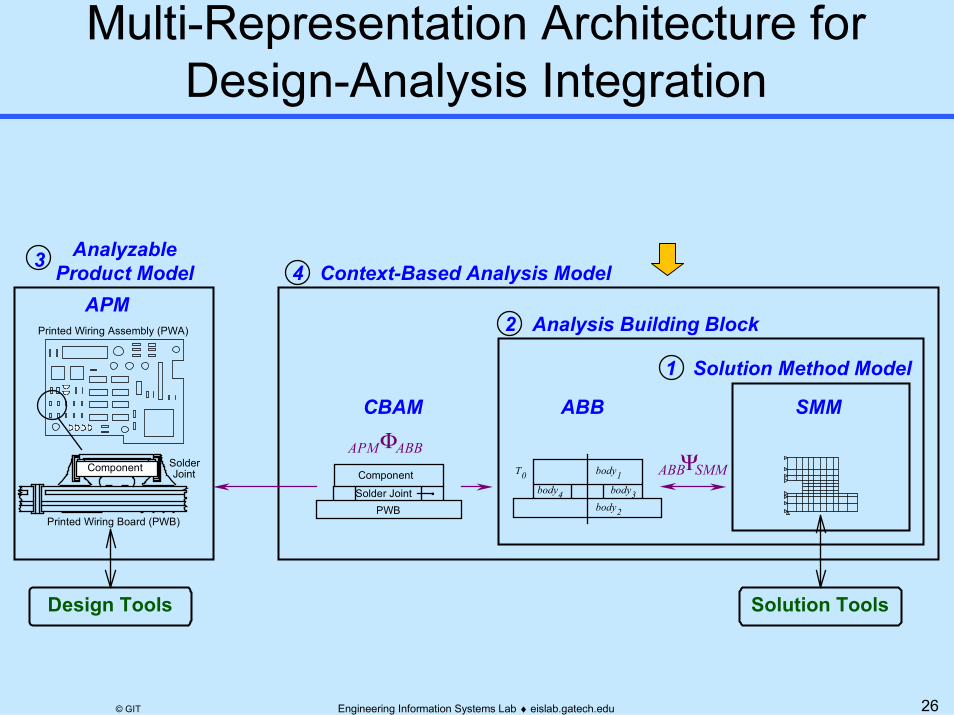
� Composed of four representations (information models)� Provides flexible, modular mapping between design & analysis models� Creates automated, product-specific analysis modules (CBAMs)� Represents design-analysis associativity explicitly
1 Solution Method Model
ΨABB SMM
2 Analysis Building Block
4 Context-Based Analysis Model3
SMMABBΦAPM ABB
CBAM
APM
Design Tools Solution Tools
Printed Wiring Assembly (PWA)
Solder Joint
Component
PWB
body3body2
body1body4
T0
Printed Wiring Board (PWB)
SolderJointComponent
AnalyzableProduct Model

19Engineering Information Systems Lab ♦ eislab.gatech.edu© GIT
Routine AnalysesPerformanceEMI - Trace Spacing VariationReliabilitySolder Joint Deformation - Thermomechanical [Engelmaier, 1989; Lau, et al., 1986; Kitano, et al. 1995]Solder Joint Fatigue - Component MisalignmentPlated Through-Hole Fatigue [Sizemore & Sitaraman,1995] ManufacturabilityReflow Soldering - PWA/B Warpage [Stiteler & Ume, 1996]Bed-of-Nails Test - PWA Deflection [Iannuzzelli, 1990]Solder Wave - Component Shadowing
ConceptualDesign
CheckLayout
1
2
3
Modified Layout
Acceptable Layout
Unacceptable Layout
DevelopPWA
Layout
ModifyLayout
Typical PWA Design Process
20Engineering Information Systems Lab ♦ eislab.gatech.edu© GIT
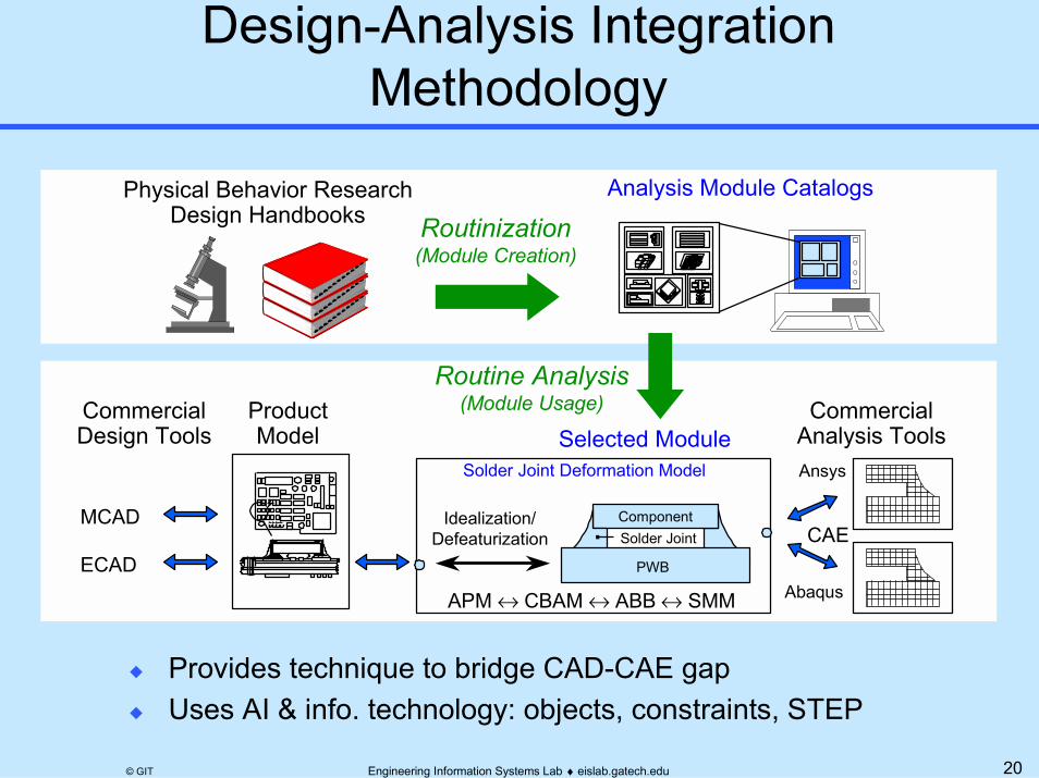
� Provides technique to bridge CAD-CAE gap� Uses AI & info. technology: objects, constraints, STEP
ProductModel Selected Module
Analysis Module Catalogs
MCAD
ECAD
Physical Behavior ResearchDesign Handbooks
CommercialAnalysis ToolsAnsys
Abaqus
Solder Joint Deformation Model
Idealization/Defeaturization
CommercialDesign Tools
PWB
Solder JointComponent
APM ↔ CBAM ↔ ABB=↔ SMM
Routine Analysis(Module Usage)
Routinization(Module Creation)
CAE
21Engineering Information Systems Lab ♦ eislab.gatech.edu© GIT
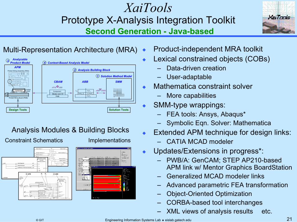
XaiToolsPrototype X-Analysis Integration Toolkit
Second Generation - Java-based
� Product-independent MRA toolkit� Lexical constrained objects (COBs)
– Data-driven creation– User-adaptable
� Mathematica constraint solver– More capabilities
� SMM-type wrappings:– FEA tools: Ansys, Abaqus*– Symbolic Eqn. Solver: Mathematica
� Extended APM technique for design links:– CATIA MCAD modeler
� Updates/Extensions in progress*:– PWB/A: GenCAM; STEP AP210-based
APM link w/ Mentor Graphics BoardStation– Generalized MCAD modeler links– Advanced parametric FEA transformation– Object-Oriented Optimization– CORBA-based tool interchanges– XML views of analysis results etc.
temperature change,=∆T
cte, α
youngs modulus, E
stress,=σ
shear modulus, G
poissons ratio, ν
shear stress,=τ shear strain, γ
thermal strain, εt
elastic strain, εe
strain, ε
r2
r1)1(2 ν−= EG
r3
r4Tt ∆=αε
Eeσε =
r5
Gτγ =
te εεε +=
Multi-Representation Architecture (MRA)
Analysis Modules & Building BlocksConstraint Schematics Implementations
deformation model
Thermal Bending System
L
αb
T
Treference
t
∆T
total diagonalpwb
total thickness
coefficient of thermal bending δ
warpage
al1
al2
mv1
al3
soldersolder joint
pwb
component
1.25
deformation model
total height
detailed shape
rectangle
[1.2]
[1.1]
average
[2.2]
[2.1]
ω cTc
Ts
inter-solder joint distanceapproximate maximum
∆γsj
L s
primary structural materialtotal thickness
linear-elastic model
Plane Strain
geometry model 3
a
stress-strainmodel 1
stress-strainmodel 2
stress-strainmodel 3
Bodies System
γ xy, extreme, 3
T2
L1
T1
T0
L2
h1
h2
T3Tsj
hs
hc
L c
γ xy, extreme, sjbilinear-elastoplastic model
linear-elastic model
primary structural material linear-elastic modelcomponentoccurrence
solder jointshear strainrange
[1.2]
[1.1]length 2 +
3 APM 2 ABB2Φ1Φ
1 Solution Method Model
ΨABB SMM
2 Analysis Building Block
4 Context-Based Analysis Model3
SMMABBΦAPM ABB
CBAM
APM
Design Tools Solution Tools
Printed Wiring Assembly (PWA)
Solder Joint
Component
PWB
body3body2
body1body4
T0
Printed Wiring Board (PWB)
SolderJointComponent
AnalyzableProduct Model

22Engineering Information Systems Lab ♦ eislab.gatech.edu© GIT
XaiTools Framework ArchitectureCompany/Product-Independent View
In-Progress & Potential Extensions as of 3/00
ODBMS*, PDM*
Other CORBAWrappers*
MCAD: CATIAIDEAS*, Pro/E*, AutoCAD*
ECAD: Mentor Graphics (AP210 WD)PWB Layup ADT, ChipPackage ADT
Accel (PDIF, GenCAM)*
FEA: Ansys, Elfini*, Abaqus*Math: Mathematica, MatLab*, MathCAD*
In-House Codes
MaterialPropertyManager
ConstraintSolver
COB Schemas
objects, x.cos, x.exp
Analysis Module Tools
Mathematica
Template Libraries: Analysis Packages*, CBAMs, ABBs, APMs, Conditions*Instances: Usage/adaptation of templates
AnalysisCodes
COB Instances
objects, x.coi, x.step
Tool Forms(parameterized
tool models/full* SMMs)
CAD Tool
PersistentObject
Repository
Design Tools
COB Server
StandardParts
Manager
asterisk (*) = in-progress/envisioned extensions
Analysis Mgt. Tools
COB Analysis ToolsNavigator: XaiTools
Editor (text & graphical*)
Pullable Views*,Condition Mgr*, ...
CORBA Wrappers
Libraries

23Engineering Information Systems Lab ♦ eislab.gatech.edu© GIT
Architecture
Client PCs
XaiTools
Thick Client
Users
Internet
Current:U-Engineer.com(pilot demo) - Ansys - Mathematica
Future:Company Intranet and/orU-Engineer.com(commercial) - Other solvers
Iona orbixdj
Mathematica
Ansys
Internet/Intranet
XaiTools AnsysSolver Server
XaiTools AnsysSolver Server
XaiTools Math.Solver Server
CORBA Daemon
XaiTools AnsysSolver Server
FEA Solvers
Math Solvers
CORBA Servers
CO
RBA IIO
P
...
Engineering Service BureauHost Machines

24Engineering Information Systems Lab ♦ eislab.gatech.edu© GIT
XaiToolsInstallation at GIT EIS Lab as of March, 2000
Client PCs
XaiTools
Thick Client
Internet
Iona orbixdj
MathematicaInternet/Intranet
XaiTools Math.Solver Server
CORBA Daemon
Math Solvers
CORBA Servers
CO
RBA IIO
P
golden.marc.gatech.edu Sun UltraSPARC 1
Regular Users• EIS Lab
Pilot Users• Phoenix AZ• Huntsville AL• Japan• etc.
Host Machines
Iona orbixdj
Mathematica
Ansys
XaiTools AnsysSolver Server
CORBA Daemon
XaiTools AnsysSolver Server
FEA Solvers
Math Solvers
CORBA Servers
hoogly.marc.gatech.edu Sun UltraSPARC 10
25Engineering Information Systems Lab ♦ eislab.gatech.edu© GIT
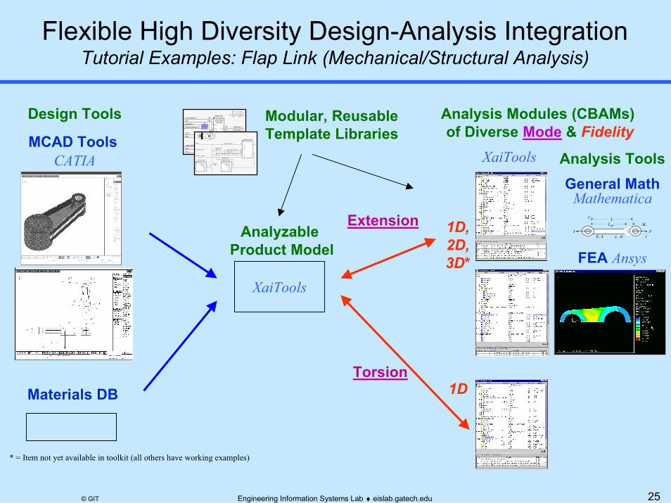
Flexible High Diversity Design-Analysis IntegrationTutorial Examples: Flap Link (Mechanical/Structural Analysis)
Analysis Modules (CBAMs) of Diverse Mode & Fidelity MCAD Tools
Materials DB
y
xPP
E, A
∆LLeff
ε=, σ=
L
FEA Ansys
General MathMathematica
Analyzable Product Model
XaiTools
XaiTools
Extension
Torsion1D
1D,2D,3D*
Modular, ReusableTemplate Libraries
CATIA
temperature change,=∆T
material model
temperature, T
reference temperature, To
cte, α
youngs modulus, E
force, F
area, A stress,=σ
undeformed length, Lo
strain,=ε
total elongation,=∆L
length, Lstart, x1
end, x2
mv6
mv5
smv1
mv1mv4
E
α
One D LinearElastic Model
(no shear)
∆T
εσ
εe
εt
thermal strain, εt
elastic strain, εe
mv3
mv2
xFF
E, A, α
∆LLo
∆T, ε=, σ=
yL
r112 xxL −=
r2
oLLL −=∆
r4
AF
=σ
sr1
oTTT −=∆
r3LL∆=ε
material
effective length, Leff
deformation model
l inear elastic model
Lo
Torsional Rod
G
ϕ
τ
J
γ
r
θ2
θ1
shear modulus, G
cross section:effective ring polar moment of inertia, J
al1
al3
al2a
linkage
mode: shaft torsion
condition reaction
t s1
A
Sle eve 1
A ts 2
ds2
ds1
Sleev e 2
L
Shaft
Le ff
θs
T
outer radius, ro al2b
stress mos model
allowable stress
twist mos model
Margin of Safety(> case)
allowableactual
MS
Margin of Safety(> case)
allowableactual
MS
allowabletwist
Analysis Tools
* = Item not yet available in toolkit (all others have working examples)
Design Tools
26Engineering Information Systems Lab ♦ eislab.gatech.edu© GIT
1 Solution Method Model
ΨABB SMM
2 Analysis Building Block
4 Context-Based Analysis Model3
SMMABBΦAPM ABB
CBAM
APM
Design Tools Solution Tools
Printed Wiring Assembly (PWA)
Solder Joint
Component
PWB
body3body2
body1body4
T0
Printed Wiring Board (PWB)
SolderJointComponent
AnalyzableProduct Model

27Engineering Information Systems Lab ♦ eislab.gatech.edu© GIT
Analysis Primitives
Beam
q(x)
Distributed Load
RigidSupport
Cantilever Beam System
Analysis Systems- Primitive building blocks - Containers of ABB "assemblies"
Material Modelsσ
ε
σ
ε
Specialized
General
- Predefined templates
- User-defined systemsAnalysis VariablesDiscrete Elements
Interconnections
Continua
Plane Strain BodyLinear-Elastic
BilinearPlastic PlateLow Cycle
Fatigue
∆ε
N
Mass Spring Damper
x
y q(x)
Beam
Distributed Load
RigidSupport
No-Slipbody 1body 2
Temperature,
Stress,
Strain,σ
ε
T
Geometry
Object representation of product-independent analytical engineering concepts

28Engineering Information Systems Lab ♦ eislab.gatech.edu© GIT
temperature change,=∆T
cte, α
youngs modulus, E
stress,=σ
shear modulus, G
poissons ratio, ν
shear stress,=τ shear strain, γ
thermal strain, εt
elastic strain, εe
strain, ε
r2
r1)1(2 ν−
= EG
r3
r4Tt ∆=αε
Eeσε =
r5
Gτγ =
te εεε +=
temperature change,=∆T
material model
temperature, T
reference temperature, To
cte, α
youngs modulus, E
force, F
area, A stress,=σ
undeformed length, Lo
strain,=ε
total elongation,=∆L
length, Lstart, x1
end, x2
mv6
mv5
smv1
mv1mv4
E
α
One D LinearElastic Model
(no shear)
∆T
εσ
εe
εt
thermal strain, εt
elastic strain, εe
mv3
mv2
xFF
E, A, α
∆LLo
∆T, ε=, σ=
yL
r1
12 xxL −=
r2
oLLL −=∆
r4
AF=σ
sr1
oTTT −=∆
r3LL∆=ε
1D Linear Elastic Model Extensional Rod
Usage by Flap Link Model

29Engineering Information Systems Lab ♦ eislab.gatech.edu© GIT
1 Solution Method Model
ΨABB SMM
2 Analysis Building Block
4 Context-Based Analysis Model3
SMMABBΦAPM ABB
CBAM
APM
Design Tools Solution Tools
Printed Wiring Assembly (PWA)
Solder Joint
Component
PWB
body3body2
body1body4
T0
Printed Wiring Board (PWB)
SolderJointComponent
AnalyzableProduct Model

30Engineering Information Systems Lab ♦ eislab.gatech.edu© GIT
SolidModeler
MaterialsDatabase
FastenersDatabase
Design Applications Analysis Applications
FEA-BasedAnalysis
Formula-BasedAnalysis
Combineinformation
Add reusablemultifidelity
idealizations
Analyzable Product Model(APM)
...Provide advanced access to design data needed by diverse analyses.
Support multidirectionality
31Engineering Information Systems Lab ♦ eislab.gatech.edu© GIT
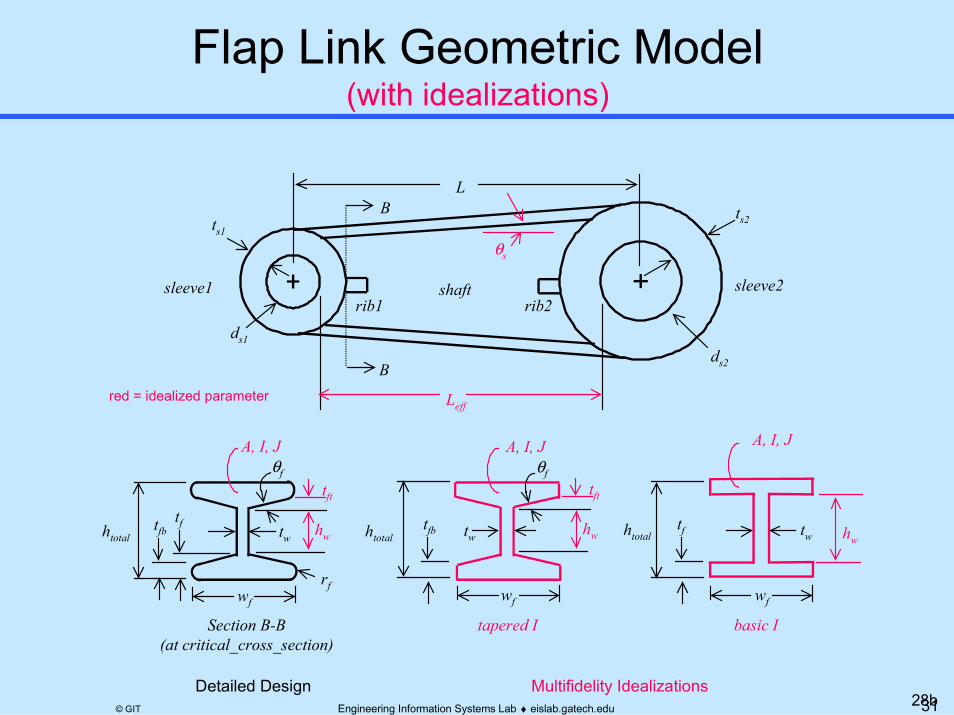
(with idealizations)
ts1
B
sleeve1
B ts2
ds2
ds1
sleeve2
L
tfb tw
wf
rf
θf
Section B-B(at critical_cross_section)
shaft
Leff
θs
tft
A, I, J
tapered I
htotaltf tw
wf
tfb tw
wf
θftft
hw hw hw
basic I
htotalhtotal
tf
Multifidelity Idealizations
A, I, J A, I, J
rib1
Detailed Design
rib2
red = idealized parameter
28b
32Engineering Information Systems Lab ♦ eislab.gatech.edu© GIT
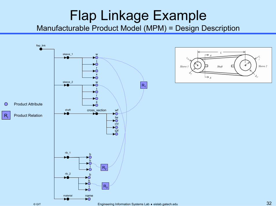
Manufacturable Product Model (MPM) = Design Description
Product Attribute
Ri Product Relation
ts1
A
Sleeve 1
A ts2
ds2
ds1
Sleeve 2
L
Shaft
b
h
t
b
h
t
sleeve_2
shaft
rib_1
material
flap_link
sleeve_1
rib_2
w
t
r
x
name
R3
R2
t2f
wf
tw
t1f
cross_section
w
t
r
x
R1

33Engineering Information Systems Lab ♦ eislab.gatech.edu© GIT
Analyzable Product Model (APM) = MPM Subset + Idealizations
flap_link
critical_section
critical_simple
t2f
wf
tw
hw
t1f
area
effective_length
critical_detailed
stress_strain_model linear_elastic
E
ν
cte area
wf
tw
hw
tf
sleeve_1
b
h
t
b
h
t
sleeve_2
shaft
rib_1
material
rib_2
w
t
r
x
name
t2f
wf
tw
t1f
cross_section
w
t
r
x
R3
R2
R1
R8
R9
R10
6R
R7
R12
11R
1R
2
3
4
5
R
R
R
R
ts1
A
Sleeve 1
A ts2
ds2
ds1
Sleeve 2
L
Shaft
Leff
θs
Product Attribute
Idealized Attribute
Ri Idealization Relation
Ri Product Relation

34Engineering Information Systems Lab ♦ eislab.gatech.edu© GIT
APMCOB Tool
7) Solve idealizations8) Use in analysis
part_number : “9162”;hole1.radius : ?;hole2.radius : ?;length1 : ?;
tk/tclCATGEOwrapper
CATIA(CAD tool)
part_number : “9162”;hole1.radius : 2.5;hole2.radius : 4.0;length1 : 20.0;
1) 2) request
4)
5)
6) response
GITInterfaceprogram
0) Designer - Creates design geometry - Defines APM-compatible parameters/tags
3)
3 and 4 similar to other CAD APIs
COB instance format
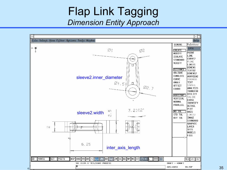
35Engineering Information Systems Lab ♦ eislab.gatech.edu© GIT
Dimension Entity Approach
inter_axis_length
sleeve2.width
sleeve2.inner_diameter

36Engineering Information Systems Lab ♦ eislab.gatech.edu© GIT
Parametric Entity Approach
inter_axis_length
sleeve2.width
sleeve2.inner_diameter

37Engineering Information Systems Lab ♦ eislab.gatech.edu© GIT
1 Solution Method Model
ΨABB SMM
2 Analysis Building Block
4 Context-Based Analysis Model3
SMMABBΦAPM ABB
CBAM
APM
Design Tools Solution Tools
Printed Wiring Assembly (PWA)
Solder Joint
Component
PWB
body3body2
body1body4
T0
Printed Wiring Board (PWB)
SolderJointComponent
AnalyzableProduct Model
38Engineering Information Systems Lab ♦ eislab.gatech.edu© GIT
material
effective length, Leff
deformation model
linear elastic model
Lo
Extensional Rod(isothermal)
F
∆L
σ
A
L
ε
E
x2
x1
youngs modulus, E
cross section area, A
al1
al3
al2
linkage
mode: shaft tension
condition reaction
allowable stress
y
xPP
E, A
∆LLeff
ε=, σ=
Lts1
A
Sleeve 1
A ts2
ds2
ds1
Sleeve 2
L
Shaft
Leff
θs
stress mos model
Margin of Safety(> case)
allowableactual
MS
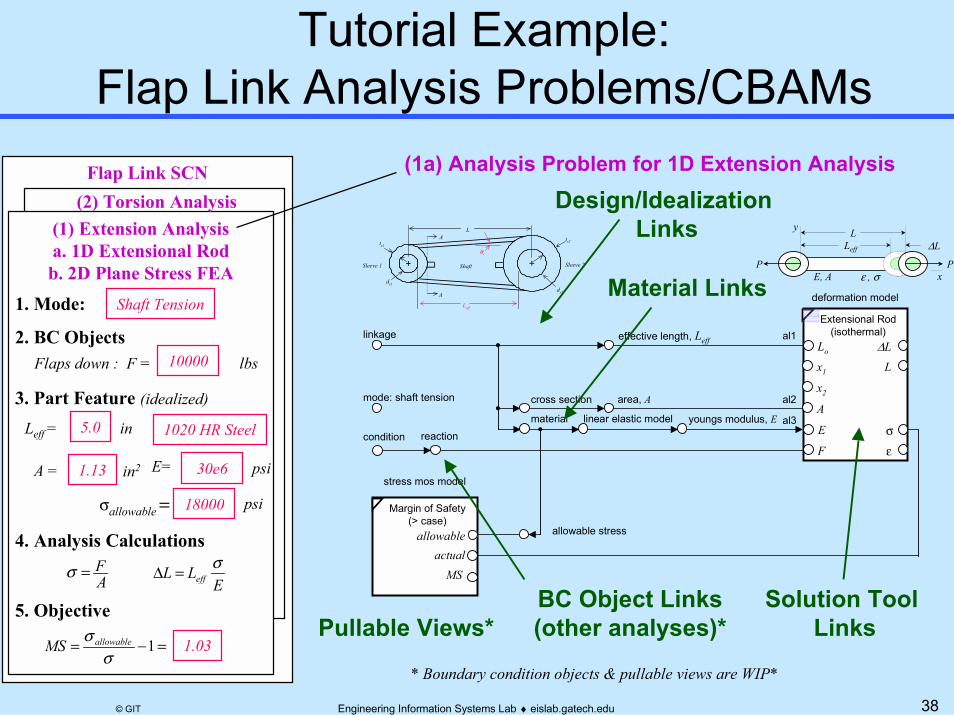
* Boundary condition objects & pullable views are WIP*
(1) Extension Analysisa. 1D Extensional Rodb. 2D Plane Stress FEA
1. Mode: Shaft Tension
2. BC ObjectsFlaps down : F =
3. Part Feature (idealized)
4. Analysis Calculations
1020 HR Steel
E= 30e6 psi
Leff = 5.0 in
10000 lbs
AF=σ
ELL eff
σ =∆
5. Objective
A = 1.13 in2
σallowable== 18000 psi
=−= 1σ
σ allowableMS 1.03
(2) Torsion Analysis
(1a) Analysis Problem for 1D Extension Analysis
Solution Tool Links
BC Object Links(other analyses)*
Design/Idealization Links
Material Links
Pullable Views*
Flap Link SCN

39Engineering Information Systems Lab ♦ eislab.gatech.edu© GIT
material
effective length, Leff
deformation model
linear elastic model
Lo
Extensional Rod(isothermal)
F
∆L
σ
A
L
ε
E
x2
x1
youngs modulus, E
cross section area, A
al1
al3
al2
linkage
mode: shaft tension
condition reaction
allowable stress
y
xPP
E, A
∆LLeff
ε=, σ=
Lts1
A
Sleeve 1
A ts2
ds2
ds1
Sleeve 2
L
Shaft
Leff
θs
stress mos model
Margin of Safety(> case)
allowableactual
MS
ν
critical_simple
t2f
wf
tw
t1fb
h
t
b
h
t
effective_length
sleeve_2
shaft
rib_1
material
flap_link
sleeve_1
rib_2
w
t
r
x
critical_detailed
name
stress_strain_model linear_elastic
E
cte
t2f
wf
tw
t1f
area
wf
tw
hw
tf
cross_section
critical_section
w
t
r
x Linkage Extensional
Model
Formula-Based PBAM(Analysis Template)
Linkage Extensional Model
Linkage Analysis Template (CBAM)
Linkage APM

40Engineering Information Systems Lab ♦ eislab.gatech.edu© GIT
COB link_extensional_model SUBTYPE_OF link_analysis_model;DESCRIPTION
"Represents 1D formula-based extensional model.";ANALYSIS_CONTEXT
PART_FEATURElink : flap_link
BOUNDARY_CONDITION_OBJECTSassociated_condition : condition;
MODE"tension";
OBJECTIVESstress_mos_model : margin_of_safety_model;
ANALYSIS_SUBSYSTEMS */deformation_model : extensional_rod_isothermal;
RELATIONSal1 : "<deformation_model.undeformed_length> == <link.effective_length>";al2 : "<deformation_model.area> == <link.shaft.critical_cross_section.basic.area>";al3 : "<deformation_model.material_model.youngs_modulus> ==
<link.material.stress_strain_model.linear_elastic.youngs_modulus>";
al4 : "<deformation_model.material_model.name> == <link.material.name>";al5 : "<deformation_model.force> == <associated_condition.reaction>";
al6 : "<stress_mos_model.allowable> == <link.material.yield_stress>";al7 : "<stress_mos_model.determined> == <deformation_model.material_model.stress>";
END_COB;
Desired categorization of attributes is shown above (as manually inserted) to support pullable views. Categorization capabilities is a planned XaiTools extension.
material
effective length, Leff
deformation model
linear elastic model
Lo
Extensional Rod(isothermal)
F
∆L
σ
A
L
ε
E
x2
x1
youngs modulus, E
cross section area, A
al1
al3
al2
linkage
mode: shaft tension
condition reaction
allowable stress
y
xPP
E, A
∆LLeff
ε=, σ=
Lts1
A
Sleeve 1
A ts2
ds2
ds1
Sleeve 2
L
Shaft
Leff
θs
stress mos model
Margin of Safety(> case)
allowableactual
MS
41Engineering Information Systems Lab ♦ eislab.gatech.edu© GIT
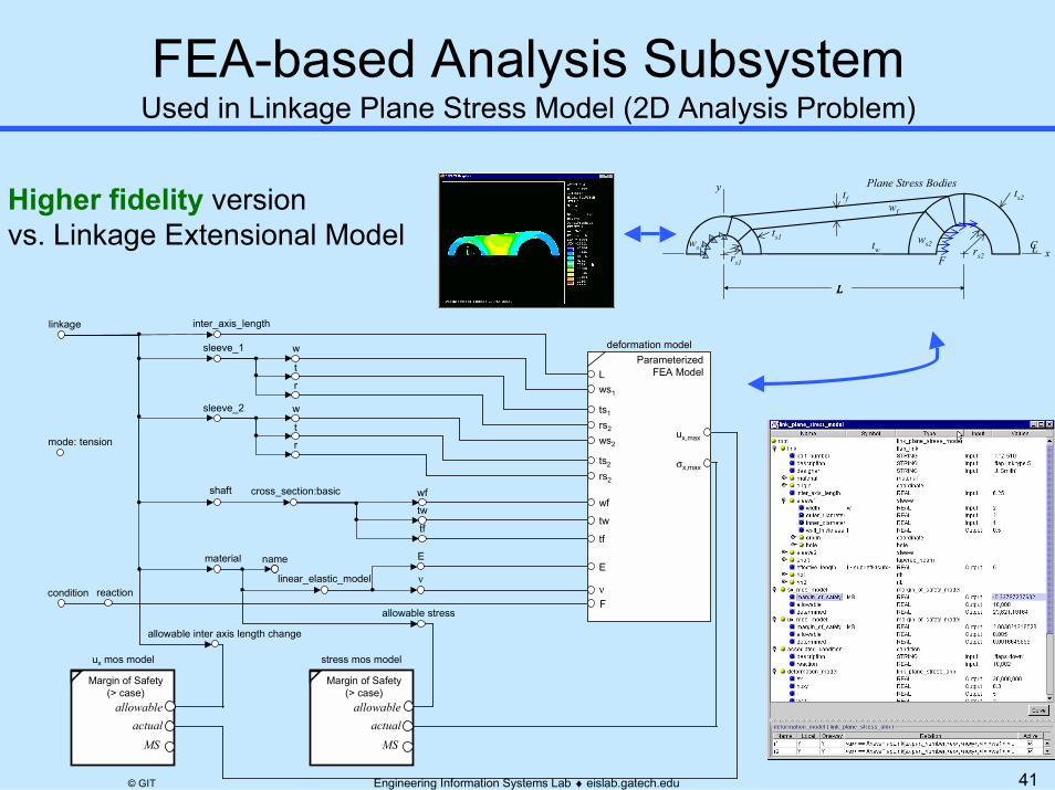
Used in Linkage Plane Stress Model (2D Analysis Problem)
ts1
rs1
L
rs2
ts2tf
ws2ws1
wf
tw
F
L L
x
y
L C
Plane Stress Bodies
Higher fidelity version vs. Linkage Extensional Model
name
linear_elastic_model ν
wftw
tf
inter_axis_length
sleeve_2
shaft
material
linkage
sleeve_1
w
t
r
E
cross_section:basic
w
t
rLws1
ts1
rs2
ws2
ts2
rs2
wf
tw
tf
E
ν
deformation model
σx,max
ParameterizedFEA Model
stress mos model
Margin of Safety(> case)
allowableactual
MS
ux mos model
Margin of Safety(> case)
allowableactual
MS
mode: tensionux,max
Fcondition reaction
allowable inter axis length change
allowable stress

42Engineering Information Systems Lab ♦ eislab.gatech.edu© GIT
material
effective length, Leff
deformation model
linear elastic model
Lo
Torsional Rod
G
ϕ
τ
J
γ
r
θ2
θ1
shear modulus, G
cross section:effective ring polar moment of inertia, J
al1
al3
al2a
linkage
mode: shaft torsion
condition reaction
ts1
A
Sleeve 1
A ts2
ds2
ds1
Sleeve 2
L
Shaft
Leff
θs
T
outer radius, ro al2b
stress mos model
allowable stress
twist mos model
Margin of Safety(> case)
allowableactual
MS
Margin of Safety(> case)
allowableactual
MS
allowabletwist
Diverse Mode (Behavior) vs. Linkage Extensional Model

43Engineering Information Systems Lab ♦ eislab.gatech.edu© GIT
CBAM = why + how = Analysis Context + Analysis Subsystems (ABBs, etc.) + Associativity Linkages• Can be new, reused, or adapted template• Instance can contain one or more runs
Analysis Context• Analysis specification (why vs. how)• Definable during early planning stages
analysis problem a.k.a: template,context-based analysis model (CBAM),
analysis module
Analysis Building Blocks
(ABBs)
idealizations
boundary variables
allowables
APM Entities
Conditions &Next-Higher
CBAMs
MSallowableactual
Boundary Condition Objects
Part Feature
Mode
Objectives
Analysis Subsystems
SolutionMethod Models
(SMMs)
AnalysisContext
Context-BasedAnalysis Model
(CBAM)
AssociativityLinkages

44Engineering Information Systems Lab ♦ eislab.gatech.edu© GIT
� Analysis Integration Challenges� Introduction to Constrained Objects (COBs)� Overview of COB-based XAI� Example Applications
� Electronic Packaging Thermomechanical Analysis� Aerospace Structural Analysis
� Summary
45Engineering Information Systems Lab ♦ eislab.gatech.edu© GIT
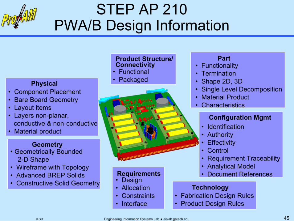
Technology
Physical
Geometry
• Component Placement• Bare Board Geometry• Layout items• Layers non-planar, conductive & non-conductive• Material product
• Geometrically Bounded 2-D Shape• Wireframe with Topology • Advanced BREP Solids • Constructive Solid Geometry
Part• Functionality• Termination • Shape 2D, 3D • Single Level Decomposition• Material Product• Characteristics
Configuration Mgmt• Identification• Authority• Effectivity• Control• Requirement Traceability• Analytical Model• Document References
Product Structure/Connectivity
• Functional• Packaged
• Fabrication Design Rules• Product Design Rules
Requirements• Design• Allocation• Constraints• Interface
46Engineering Information Systems Lab ♦ eislab.gatech.edu© GIT
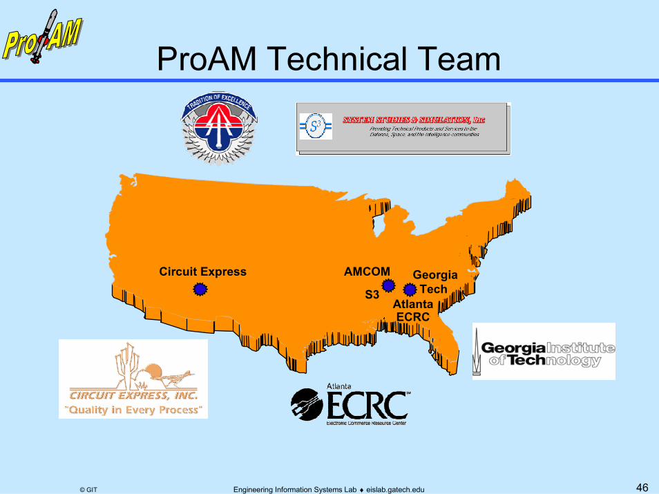
Circuit Express
AtlantaECRC
GeorgiaTech
AMCOM
S3

47Engineering Information Systems Lab ♦ eislab.gatech.edu© GIT
Highly Automated Internet-based Analysis Modules
World WideEnd UserAMCOM
Feedback,Products Atlanta
Physical SimulationU-Engineer.com
Internet-basedEngineering Service
Bureau
Self-ServeResults
Response to RFP,Technical Feedback,Products
Missile Mfg.Prime 1
TempePWB Fabricator
Life CycleNeeds
FrionaPWB Fabricator
SME 2
RockhillPWB Fabricator
SME 1 SME n
…
IdealizedProductData
ProAM Focus
RFP with Product Data (STEP, IPC, …)

48Engineering Information Systems Lab ♦ eislab.gatech.edu© GIT
� Typically niche-experts– Precise mfg. process knowledge– Specialized product design knowledge
(ex. PWB laminates)� SME analysis needs
– Product improvements (DFM)– Mfg. process troubleshooting– Mfg. process optimization
� More accurate data → Better analysis� Bottom line drivers:Higher Yields, Lower Cost,
Better Quality, Fewer Delays

49Engineering Information Systems Lab ♦ eislab.gatech.edu© GIT
� Lack of awareness� High costs of traditional analysis capability
– Secondary: Specialized Software, Training, Hardware – Primary: Model Access/Development, Validation, Usage
� Lack of domain-specific integrated tools
Skilled PersonnelProduct Model Analysis Model

50Engineering Information Systems Lab ♦ eislab.gatech.edu© GIT
Lower cost, better quality, fewer delays in supply chain
Analysis Documentation Ready-to-Use Analysis Modules

51Engineering Information Systems Lab ♦ eislab.gatech.edu© GIT
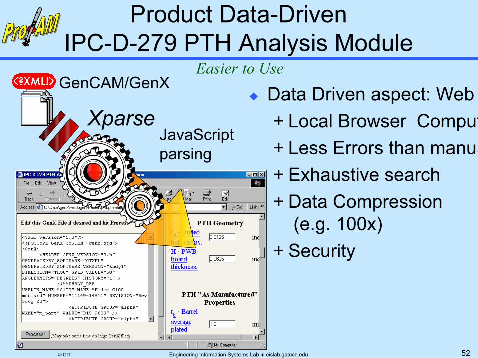
PTH/PTV Fatigue Life Estimation
Tedious to Use
52Engineering Information Systems Lab ♦ eislab.gatech.edu© GIT
� Data Driven aspect: Web + Local Browser Comput+ Less Errors than manua+ Exhaustive search+ Data Compression
(e.g. 100x)+ Security
XparseJavaScriptparsing
GenCAM/GenXEasier to Use

53Engineering Information Systems Lab ♦ eislab.gatech.edu© GIT
Web-based Approach
html form
html page
http
Analysis Toolscript
html page
ftp
emailnotification
SMEClient
ESB WebServer
ESB AnalysisServer
Sun SPARCstationMathematica
Pentium PChttpd, etc.
Pentium PCWeb Browser
smtp
54Engineering Information Systems Lab ♦ eislab.gatech.edu© GIT
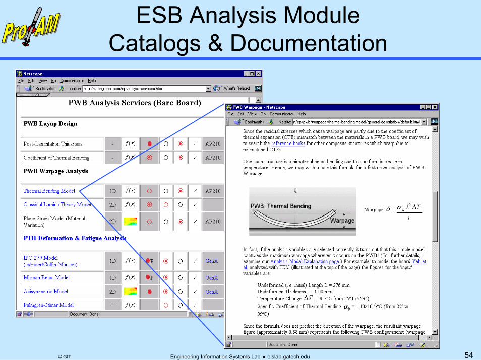
ESB Analysis ModuleCatalogs & Documentation
55Engineering Information Systems Lab ♦ eislab.gatech.edu© GIT
� Self-serve analysis– Pre-developed analysis modules
presented in product & process contexts– Available via the Internet– Optionally standards-driven (STEP, GenCAM ...):
» Reduce manual data transformation & re-entry» Highly automated plug-and-play usage
– Enabled by X-analysis integration technology� Full-serve analysis as needed� Possible business models:
(beyond ProAM scope)– Pay-per-use and/or Pay-per-period
Costs averaged across customer base

56Engineering Information Systems Lab ♦ eislab.gatech.edu© GIT
ProAM Design-Analysis IntegrationElectronic Packaging Examples: PWA/B
Analysis Modules (CBAMs) of Diverse Mode & Fidelity
Design Tools
Laminates DB
FEA Ansys
General MathMathematica
Analyzable Product Model
XaiToolsPWA-B
XaiToolsPWA-B
Solder JointDeformation*
PTHDeformation & Fatigue**
1D,2D
1D,2D,3D
Modular, ReusableTemplate Libraries
ECAD Tools Mentor Graphics,
Accel*
temperature change,=∆T
material model
temperature, T
reference temperature, To
cte, α
youngs modulus, E
force, F
area, A stress,=σ
undeformed length, Lo
strain,=ε
total elongation,=∆L
length, L
start, x1
end, x2
mv6
mv5
smv1
mv1mv4
E
α
One D LinearElastic Model
(no shear)
∆T
εσ
εe
εt
thermal strain, εt
elastic strain, εe
mv3
mv2
xFF
E, A, α
∆LLo
∆T, ε=, σ=
yL
r112 xxL −=
r2
oLLL −=∆
r4
AF
=σ
sr1
oTTT −=∆
r3LL∆=ε
material
effective length, Leff
deformation model
l inear elastic model
Lo
Torsional Rod
G
ϕ
τ
J
γ
r
θ2
θ1
shear modulus, G
cross section:effective ring polar moment of inertia, J
al1
al3
al2a
linkage
mode: shaft torsion
condition reaction
t s1
A
Sle eve 1
A ts 2
ds2
ds1
Sleev e 2
L
Shaft
Le ff
θs
T
outer radius, ro al2b
stress mos model
allowable stress
twist mos model
Margin of Safety(> case)
allowableactual
MS
Margin of Safety(> case)
allowableactual
MS
allowabletwist Analysis Tools
PWBWarpage
1D,2D
Materials DB
PWB Layup ToolXaiTools PWA-B
STEP AP210‡ GenCAM**,
PDIF*
‡ AP210 DIS WD1.7 * = Item not yet available in toolkit (all others have working examples) ** = Item available via U-Engineer.com

57Engineering Information Systems Lab ♦ eislab.gatech.edu© GIT
(partial)
<component occurrences>
Resistor Capacitor
STEP EXPRESS-G Notation
attribute 2 S[1:?] (a set) Entity C
attribute 1 Entity B
Entity A1 (a subclass) [ISO 10303-11]
Entity = Class of Objects
Entity A
costInteger
Currency
part number
PhysicalObject
SolidMaterialdescription
ImageString
primary structural materialphotos
IntegratedComponent
DiscreteNetwork
Micro-Processor
PWB PWAbody style ElectricalComponent
pwb
PWB Layermagnitudetolerance
Transistor
DiscreteComponent
Diode
Inductor
power ratingSolderJoint
PWAComponentOccurrence
ComponentOccurrence
referencedesignatorlocation
solder joint
surface
<location><component>
AssemblyMultimaterialPart
UnimaterialPart component occurrences
assemblycomponent
2DLocation
total length
total widthtotal height
rotation
xy
<assembly>layers
Part
58Engineering Information Systems Lab ♦ eislab.gatech.edu© GIT
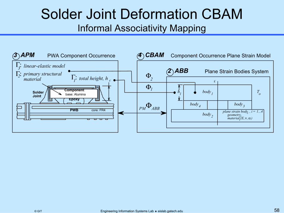
Informal Associativity Mapping
Plane Strain Bodies System
PWA Component Occurrence
CL
1
νmaterial ,E( α, )geometry
body
plane strain body , i = 1...4PWB
SolderJoint
Epoxy
Componentbase: Alumina
core: FR4
Component Occurrence Plane Strain Model
total height, h
linear-elastic model
Φ1
Φ2
ΦABBPM
Γ:1
Γ:3 APM 4 CBAM
2 ABBc
4body 3body
2body
1h oT
primary structural material
Γ:3
2
ii
i

59Engineering Information Systems Lab ♦ eislab.gatech.edu© GIT
soldersolder joint
pwb
component
1.25
deformation model
total height
detailed shape
rectangle
[1.2]
[1.1]
average
[2.2]
[2.1]
ω cTc
Ts
inter-solder joint distanceapproximate maximum
∆γsj
L s
primary structural materialtotal thickness
linear-elastic model
Plane Strain
geometry model 3
a
stress-strainmodel 1
stress-strainmodel 2
stress-strainmodel 3
Bodies System
γ xy, extreme, 3
T2
L1
T1
T0
L2
h1
h2
T3Tsj
hs
hc
L c
γ xy, extreme, sjbilinear-elastoplastic model
linear-elastic model
primary structural material linear-elastic modelcomponentoccurrence
solder jointshear strainrange
[1.2]
[1.1]length 2 +
Constraint Schematic3 APM 2 ABB2Φ1Φ
60Engineering Information Systems Lab ♦ eislab.gatech.edu© GIT
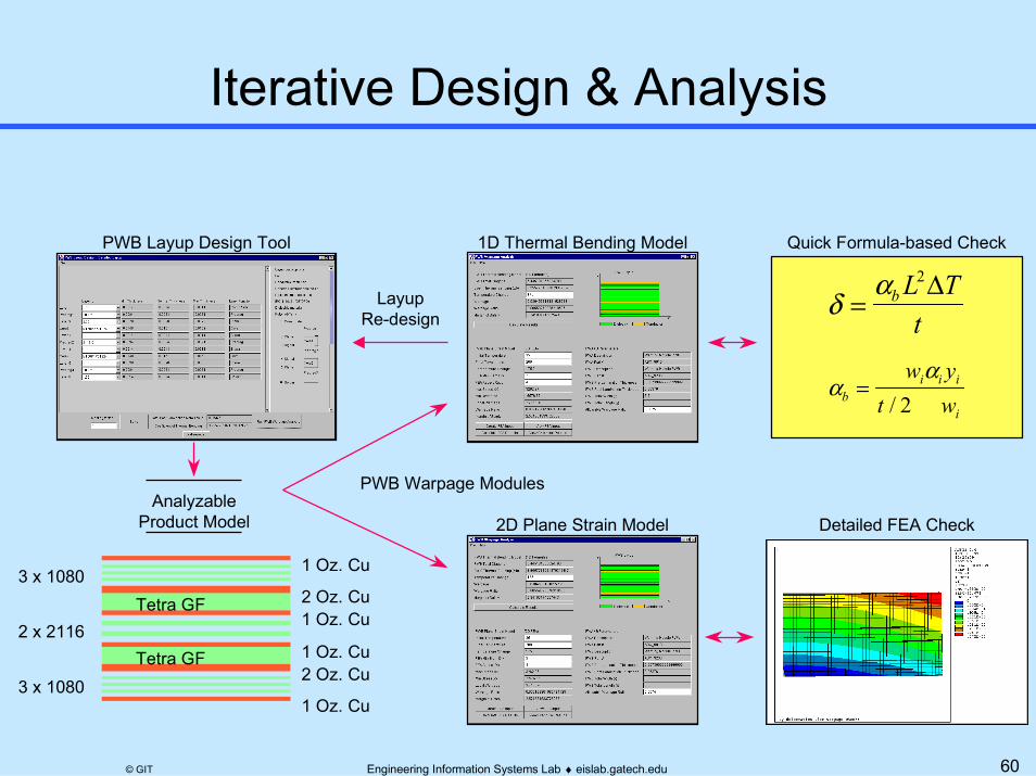
AnalyzableProduct Model
PWB Layup Design Tool
1 Oz. Cu
1 Oz. Cu
1 Oz. Cu
1 Oz. Cu
2 Oz. Cu
2 Oz. CuTetra GF
Tetra GF
3 x 1080
3 x 1080
2 x 2116
2D Plane Strain Model
δα
= b L Tt
2∆
Detailed FEA Check
αα
bi i i
i
w yt w
=/ 2
1D Thermal Bending Model
LayupRe-design
PWB Warpage Modules
Quick Formula-based Check
61Engineering Information Systems Lab ♦ eislab.gatech.edu© GIT
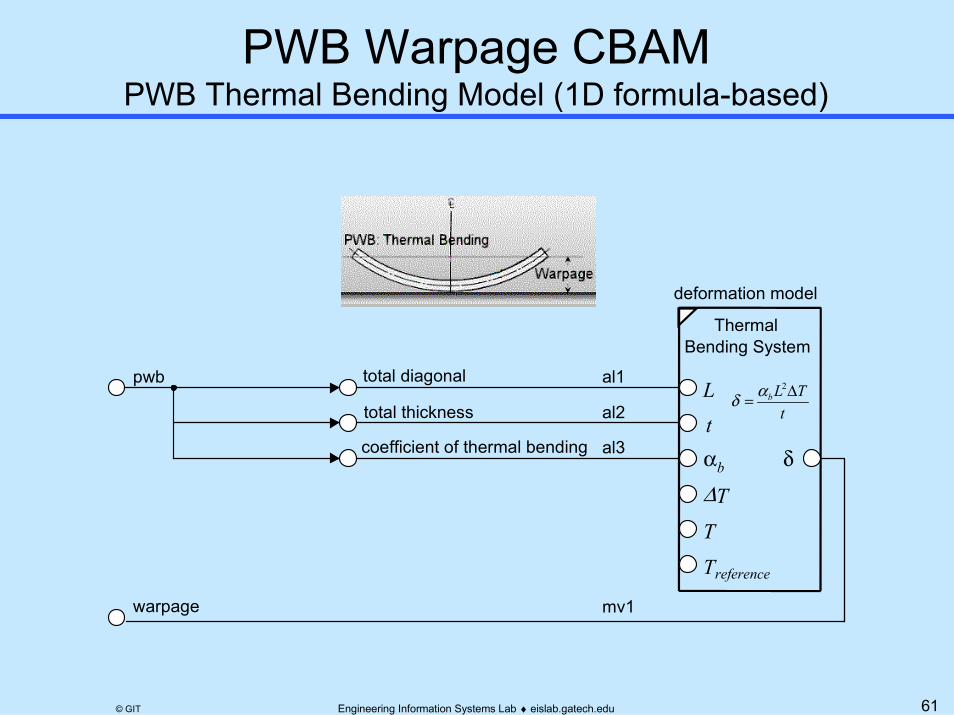
PWB Thermal Bending Model (1D formula-based)
deformation model
Thermal Bending System
L
αb
T
Treference
t
∆T
total diagonalpwb
total thickness
coefficient of thermal bending δ
warpage
al1
al2
mv1
al3
tTLb ∆=
2αδ

62Engineering Information Systems Lab ♦ eislab.gatech.edu© GIT
Flexible High Diversity Design-Analysis IntegrationElectronic Packaging Examples: Chip Packages/Mounting
(Project with Shinko Electric)
EBGA, PBGA, QFP
CuGround
PKG
Chip
Γ
Analysis Modules (CBAMs) of Diverse Mode & Fidelity
FEAAnsys
General MathMathematica
Analyzable Product Model
XaiTools
XaiToolsChipPackage
ThermalResistance
3D
Modular, ReusableTemplate Librariestemperature change,=∆T
material model
temperature, T
reference temperature, To
cte, α
youngs modulus, E
force, F
area, A stress,=σ
undeformed length, Lo
strain,=ε
total elongation,=∆L
length, L
start, x1
end, x2
mv6
mv5
smv1
mv1mv4
E
α
One D LinearElastic Model
(no shear)
∆T
εσ
εe
εt
thermal strain, εt
elastic strain, εe
mv3
mv2
xFF
E, A, α
∆LLo
∆T, ε=, σ=
yL
r112 xxL −=
r2
oLLL −=∆
r4
AF
=σ
sr1
oTTT −=∆
r3LL∆=ε
material
effective length, Leff
deformation model
l inear elastic model
Lo
Torsional Rod
G
ϕ
τ
J
γ
r
θ2
θ1
shear modulus, G
cross section:effective ring polar moment of inertia, J
al1
al3
al2a
linkage
mode: shaft torsion
condition reaction
t s1
A
Sle eve 1
A ts 2
ds2
ds1
Sleev e 2
L
Shaft
Le ff
θs
T
outer radius, ro al2b
stress mos model
allowable stress
twist mos model
Margin of Safety(> case)
allowableactual
MS
Margin of Safety(> case)
allowableactual
MS
allowabletwist Analysis Tools
Design Tools
PWB DBMaterials DB*
Prelim/APM Design ToolXaiTools ChipPackage
ThermalStress
Basic3D**
** = Demonstration module
BasicDocumentation
Automation AuthoringMS Excel
63Engineering Information Systems Lab ♦ eislab.gatech.edu© GIT
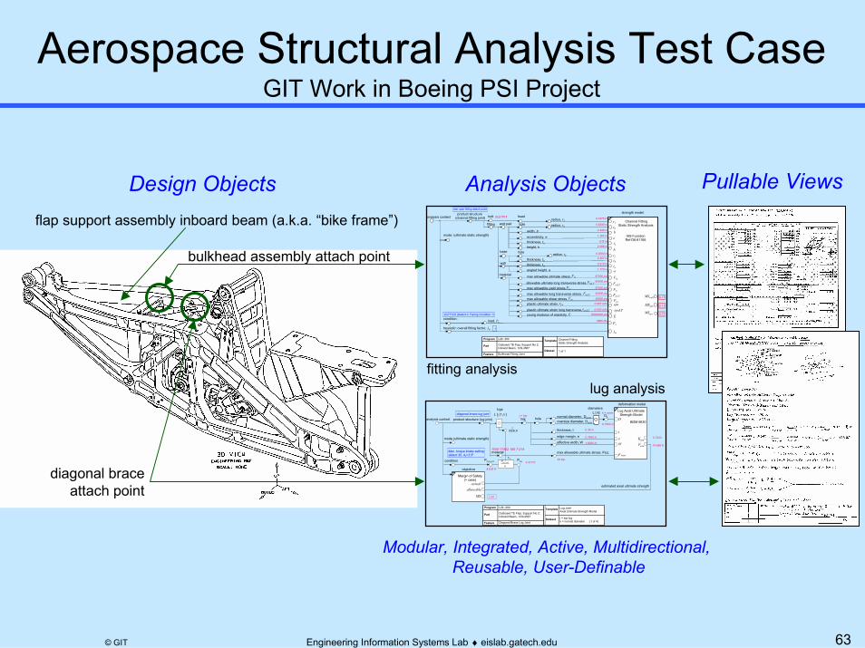
GIT Work in Boeing PSI Project
Analysis Objects
Modular, Integrated, Active, Multidirectional, Reusable, User-Definable
diagonal brace lug joint j = top
0.7500 in
0.35 in
0.7500 in
1.6000 in
2
0.7433
14.686 K
2.40
4.317 K
8.633 K
k = norm
Max. torque brake settingdetent 30, θ2=3.5º
7050-T7452, MS 7-214
67 Ksi
L29 -300
Outboard TE Flap, Support No 2;Inboard Beam, 123L4567
Diagonal Brace Lug Joint
Program
Part
Feature
Lug JointAxial Ultimate Strength Model
Template
j = top lugk = normal diameter (1 of 4)
Dataset
material
deformation model
max allowable ultimate stress, FtuL
effective width, W
analysis context
objective
mode (ultimate static strength)
condition
estimated axial ultimate strength
Margin of Safety(> case)
allowableactual
MS
normal diameter, Dnorm
thickness, t
edge margin, e
Plug joint
size,n
lugs
lugj hole
diameters
product structure (lug joint)
r1
nP jointlug
L [ j:1,n ]
Plug
L [ k]Dk
oversize diameter, DoverD
PaxuWe
t
F tuax
Kaxu
Lug Axial UltimateStrength Model
BDM 6630
0.4375 in
0.5240 in
0.0000 in
2.440 in
1.267 in
0.307 in
0.5 in
0.310 in
2.088 in
1.770 in
67000 psi
65000 psi
57000 psi
52000 psi
39000 psi
0.067 in/in
0.030 in/in
5960 Ibs
1
10000000 psi
9.17
5.11
9.77
rear spar fitting attach point
BLE7K18
2G7T12U (Detent 0, Fairing Condition 1)
L29 -300
Outboard TE Flap, Support No 2;Inboard Beam, 123L4567
Bulkhead Fitting Joint
Program
Part
Feature
Channel FittingStatic Strength Analysis
Template
1 of 1Dataset
strength model
r1
eb
h
tb
te
Pu
Ftu
E
r2
r0
a
FtuLT
Fty
FtyLT
epuLT
tw
MSwall
epu
jm
MSepb
MSeps
Channel FittingStatic Strength Analysis
Fsu
IAS FunctionRef D6-81766
end pad
base
material
wall
analysis context
mode: (ultimate static strength)
condition:
heuristic: overall fitting factor, Jm
bolt
fitting
headradius, r1
hole radius, rowidth, b
eccentricity, ethickness, teheight, h
radius, r2thickness, tb
hole
thickness, twangled height, a
max allowable ultimate stress,
allowable ultimate long transverse stress,max allowable yield stress,
max allowable long transverse stress,max allowable shear stress,plastic ultimate strain,
plastic ultimate strain long transverse,young modulus of elasticity,
load, Pu
Ftu
Fty
FtyLTFsu
epu
epuLT
E
FtuLT
product structure (channel fitting joint)flap support assembly inboard beam (a.k.a. “bike frame”)
bulkhead assembly attach point
diagonal braceattach point
Pullable Views
lug analysis fitting analysis
Design Objects
64Engineering Information Systems Lab ♦ eislab.gatech.edu© GIT
Analysis Tools
0.4375 in
0.5240 in
0.0000 in
2.440 in
1.267 in
0.307 in
0.5 in
0.310 in
2.088 in
1.770 in
67000 psi
65000 psi
57000 psi
52000 psi
39000 psi
0.067 in/in
0.030 in/in
5960 Ibs
1
10000000 psi
9.17
5.11
9.77
rear spar fitting at tach point
BLE7K18
2G7T12U (Detent 0, Fairing Condition 1)
L29 -300
Outboard TE Flap, Support No 2;Inboard Beam, 123L4567
Bulkhead Fitt ing Joint
Program
Part
Feature
Channel Fitt ingStatic Strength Analysis
Template
1 of 1Dataset
strength model
r1
eb
h
tb
te
Pu
Ftu
E
r2
r0
a
FtuLT
Fty
FtyLT
epuLT
tw
MSwall
epu
jm
MSepb
MSeps
Channel FittingStatic Strength Analysis
Fsu
IAS FunctionRef D6-81766
end pad
base
material
wall
analysis context
mode: (ultimate static strength)
condition:
heuristic: overall fitting factor, Jm
bolt
fitting
headradius, r1
hole radius, ro
width, b
eccentricity, ethickness, teheight, h
radius, r2
thickness, tb
hole
thickness, tw
angled height, a
max allowable ultimate stress,
allowable ultimate long transverse stress,max allowable yield stress,
max allowable long transverse stress,max allowable shear stress,plastic ultimate strain,
plastic ultimate strain long transverse,young modulus of elasticity,
load, Pu
Ftu
Fty
FtyLT
Fsu
epu
epu LT
E
FtuLT
product structure (channel fitting joint)
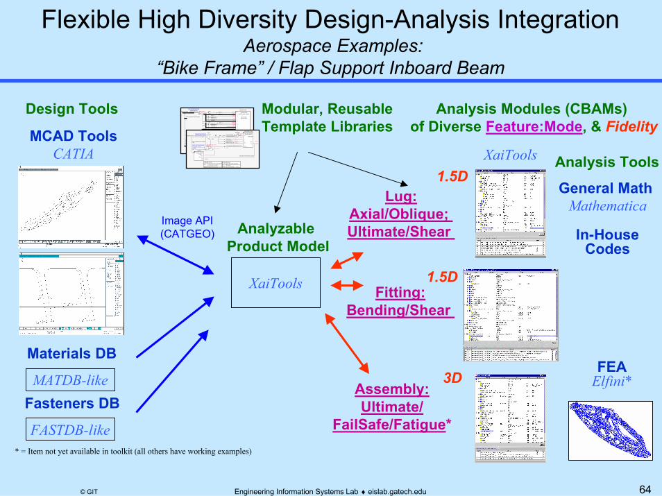
Flexible High Diversity Design-Analysis Integration Aerospace Examples:
“Bike Frame” / Flap Support Inboard Beam
Analysis Modules (CBAMs) of Diverse Feature:Mode, & Fidelity
Design Tools
Materials DBFEA
Elfini*MATDB-like
Analyzable Product Model
XaiTools
XaiTools
Fitting:Bending/Shear
3D
1.5D
Modular, ReusableTemplate LibrariesMCAD Tools
CATIA
Lug:Axial/Oblique; Ultimate/Shear
1.5D
Assembly:Ultimate/
FailSafe/Fatigue** = Item not yet available in toolkit (all others have working examples)
diagonal brace lug joint j = top
0.7500 in
0.35 in
0.7500 in
1.6000 in
2
0.7433
14.686 K
2.40
4.317 K
8.633 K
k = norm
Max. torque brake settingdetent 30, θ2=3.5º
7050-T7452, MS 7-214
67 Ksi
L29 -300
Outboard TE Flap, Support No 2;Inboard Beam, 123L4567
Diagonal Brace Lug Joint
Program
Part
Feature
Lug JointAxial Ultimate Strength Model
Template
j = top lugk = normal diameter (1 of 4)Dataset
material
deformation model
max allowable ultimate stress, FtuL
effective width, W
analysis context
objective
mode (ultimate static strength)
condition
estimated axial ultimate strength
Margin of Safety(> case)
allowableactual
MS
normal diameter, Dnorm
thickness, t
edge margin, e
Plug join t
size,n
lugs
lugj hole
diameters
product structure (lug joint)
r1
nP jointlug
L [ j:1,n ]
Plug
L [ k]Dk
oversize diameter, DoverD
PaxuWe
t
F tuax
Kaxu
Lug Axial UltimateStrength Model
BDM 6630
Fasteners DB
FASTDB-like
General Math Mathematica
In-HouseCodes
Image API(CATGEO)

65Engineering Information Systems Lab ♦ eislab.gatech.edu© GIT
from DM 6-81766 Design Manual
Channel Fitting End Pad Bending Analysis
AngleFitting
BathtubFitting
ChannelFitting
Categories of Idealized FittingsCalculation Steps
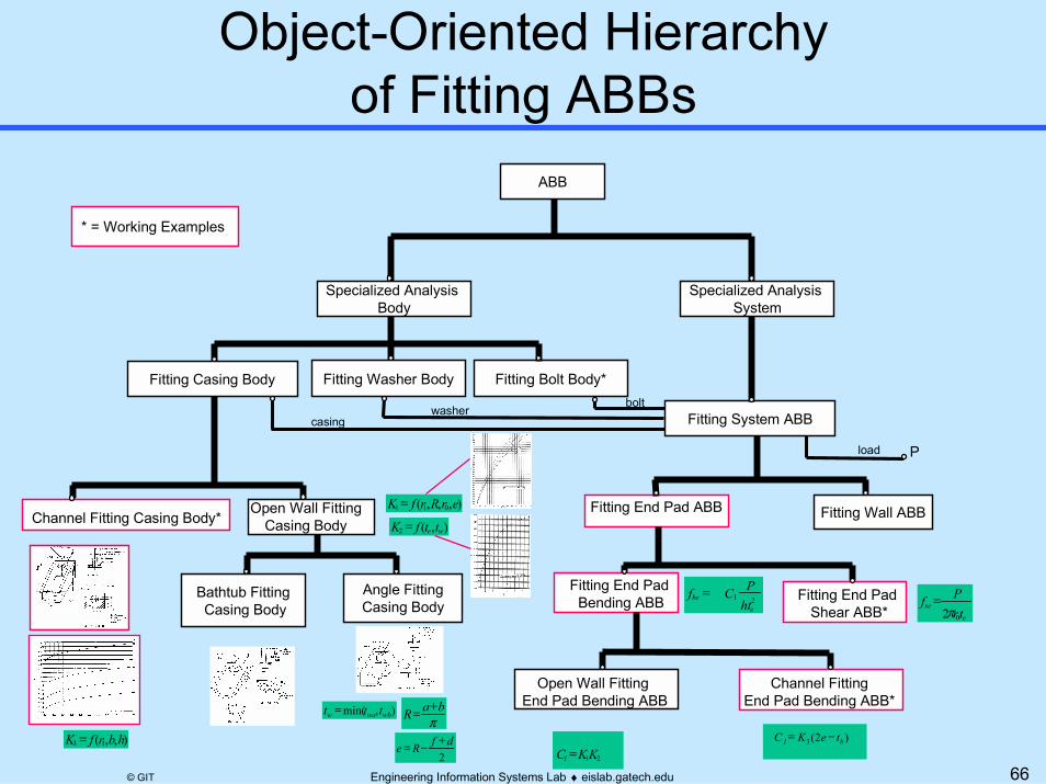
66Engineering Information Systems Lab ♦ eislab.gatech.edu© GIT
Fitting Casing Body
Channel Fitting Casing Body*
Bathtub Fitting Casing Body
Angle FittingCasing Body
Fitting System ABB
Fitting Wall ABBFitting End Pad ABB
Fitting Bolt Body*
Open Wall FittingCasing Body
Fitting End Pad Bending ABB Fitting End Pad
Shear ABB*
Open Wall Fitting End Pad Bending ABB
Channel FittingEnd Pad Bending ABB*
ese
trPf02π
=
3 )2( b 1 teKC −=
21e
behtPCf =
21 1 KKC =
),,,( 011 erRrfK =
),(2 we ttfK =
),,( 13 hbrfK =π
baR +=
2dfRe
+−=
),min( wbwaw ttt =
bolt
load
Fitting Washer Body
Specialized Analysis Body
P
ABB
Specialized Analysis System
washercasing
* = Working Examples

67Engineering Information Systems Lab ♦ eislab.gatech.edu© GIT
r1
sefactual shear stress,bolt.head.radius, r0
end_pad.thickness, te
load, P ese
trPf02π
=
Channel Fitting System ABBsEnd Pad Bending Analysis
End Pad Shear Analysis
end_pad.eccentricity, e
end_pad.width, b
bolt.hole.radius, r1
r2 r3
r1
hr1
hbend_pad.height, h
3K
befactual bending stress,
channel fitting factor,
DM 6-81766 Figure 3.3
base.thickness, tb end_pad.thickness, te load, P
23 )2(e
bbeht
PteKf −=
68Engineering Information Systems Lab ♦ eislab.gatech.edu© GIT
0.1
0.2
0.3
0.41
1.5
2
2.5
3
0.4
0.6
0.8
1
0.1
0.2
0.3
0.4
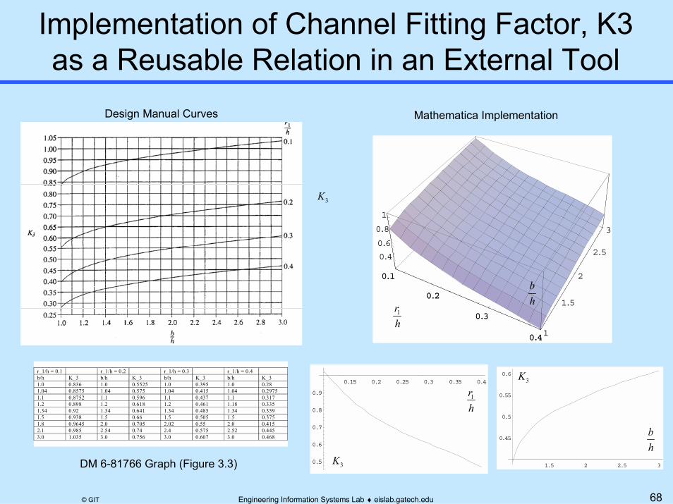
Implementation of Channel Fitting Factor, K3as a Reusable Relation in an External Tool
r_1/h = 0.1 r_1/h = 0.2 r_1/h = 0.3 r_1/h = 0.4b/h K_3 b/h K_3 b/h K_3 b/h K_31.0 0.836 1.0 0.5525 1.0 0.395 1.0 0.281.04 0.8575 1.04 0.575 1.04 0.415 1.04 0.29751.1 0.8752 1.1 0.596 1.1 0.437 1.1 0.3171.2 0.898 1.2 0.618 1.2 0.461 1.18 0.3351.34 0.92 1.34 0.641 1.34 0.485 1.34 0.3591.5 0.938 1.5 0.66 1.5 0.505 1.5 0.3751.8 0.9645 2.0 0.705 2.02 0.55 2.0 0.4152.1 0.985 2.54 0.74 2.4 0.575 2.52 0.4453.0 1.035 3.0 0.756 3.0 0.607 3.0 0.468
DM 6-81766 Graph (Figure 3.3) 1.5 2 2.5 3
0.45
0.5
0.55
0.60.15 0.2 0.25 0.3 0.35 0.4
0.5
0.6
0.7
0.8
0.9
Mathematica Implementation
3K
3K
3K
hb
hr1
hb
hr1
Design Manual Curves

69Engineering Information Systems Lab ♦ eislab.gatech.edu© GIT
Reusable Channel FittingAnalysis Module (CBAM)
strength model
r1
eb
h
tb
te
Pu
Ftu
E
r2
r0
a
FtuLT
Fty
FtyLT
epuLT
tw
MSwall
epu
jm
MSepb
MSeps
Channel FittingStatic Strength Analysis
Fsu
IAS FunctionRef DM 6-81766
end pad
base
material
wall
analysis context
mode: (ultimate static strength)
condition:
heuristic: overall fitting factor, Jm
bolt
fitting
headradius, r1
hole radius, ro
width, b
eccentricity, ethickness, teheight, h
radius, r2
thickness, tb
hole
thickness, twangled height, a
max allowable ultimate stress,
allowable ultimate long transverse stress,max allowable yield stress,
max allowable long transverse stress,max allowable shear stress,plastic ultimate strain,
plastic ultimate strain long transverse,young modulus of elasticity,
load, Pu
Ftu
Fty
FtyLTFsu
epu
epuLT
E
FtuLT
product structure (channel fitting joint)

70Engineering Information Systems Lab ♦ eislab.gatech.edu© GIT
Diagonal Brace Lug Bulkhead Fitting Casing
APM Associativity with Tagged CATIA Model
Bike Frame CATIA CAD Model
rib8.thickness
cavity3.inner_width
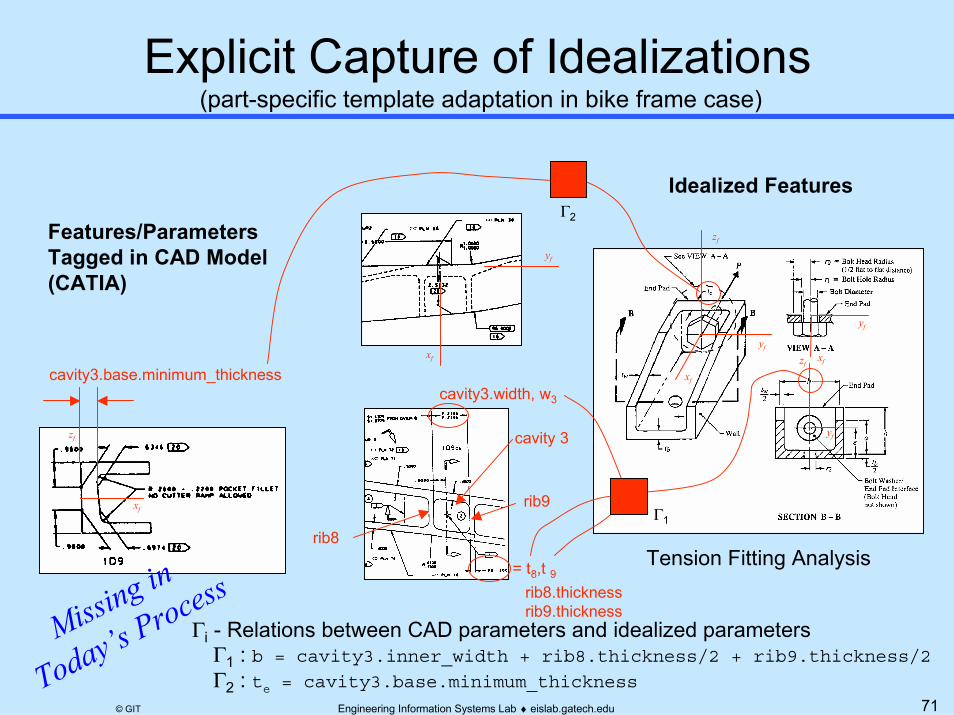
71Engineering Information Systems Lab ♦ eislab.gatech.edu© GIT
(part-specific template adaptation in bike frame case)
Features/ParametersTagged in CAD Model (CATIA)
zf
xf
cavity3.base.minimum_thickness
yf
xf
rib8
cavity 3
rib9
= t8,t 9rib8.thicknessrib9.thickness
cavity3.width, w3
zf
yf
xf
zfxf
yf
Γi - Relations between CAD parameters and idealized parameters====Γ1 : b = cavity3.inner_width + rib8.thickness/2 + rib9.thickness/2
====Γ2 : te = cavity3.base.minimum_thickness
Idealized Features
Tension Fitting Analysis
yf
Missing in
Today’s Process
Γ2
Γ1

72Engineering Information Systems Lab ♦ eislab.gatech.edu© GIT
Today’s Typical Fitting Analysis
Idealized CAD data
manually transformed
and input
Missing
Design-Analysis
Associativity
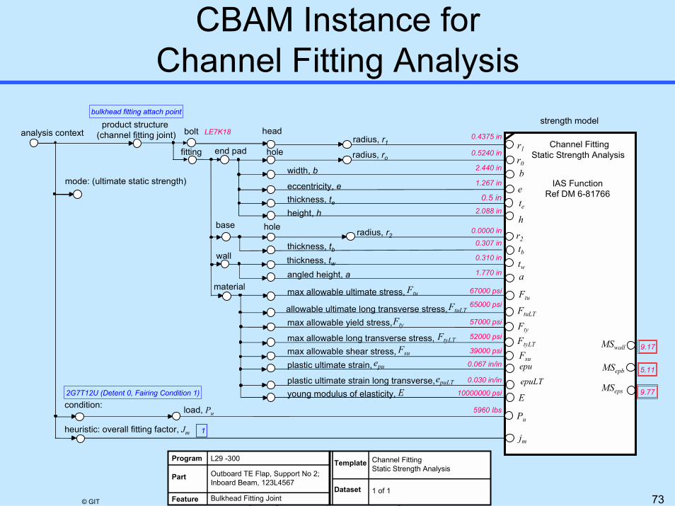
73Engineering Information Systems Lab ♦ eislab.gatech.edu© GIT
0.4375 in
0.5240 in
0.0000 in
2.440 in
1.267 in
0.307 in
0.5 in
0.310 in
2.088 in
1.770 in
67000 psi
65000 psi
57000 psi
52000 psi
39000 psi
0.067 in/in
0.030 in/in
5960 Ibs
1
10000000 psi
9.17
5.11
9.77
bulkhead fitting attach point
LE7K18
2G7T12U (Detent 0, Fairing Condition 1)
L29 -300
Outboard TE Flap, Support No 2;Inboard Beam, 123L4567
Bulkhead Fitting Joint
Program
Part
Feature
Channel FittingStatic Strength Analysis
Template
1 of 1Dataset
strength model
r1
eb
h
tb
te
Pu
Ftu
E
r2
r0
a
FtuLT
Fty
FtyLT
epuLT
tw
MSwall
epu
jm
MSepb
MSeps
Channel FittingStatic Strength Analysis
Fsu
IAS FunctionRef DM 6-81766
end pad
base
material
wall
analysis context
mode: (ultimate static strength)
condition:
heuristic: overall fitting factor, Jm
bolt
fitting
headradius, r1
hole radius, ro
width, b
eccentricity, ethickness, teheight, h
radius, r2
thickness, tb
hole
thickness, twangled height, a
max allowable ultimate stress,
allowable ultimate long transverse stress,max allowable yield stress,
max allowable long transverse stress,max allowable shear stress,plastic ultimate strain,
plastic ultimate strain long transverse,young modulus of elasticity,
load, Pu
Ftu
Fty
FtyLTFsu
epu
epuLT
E
FtuLT
product structure (channel fitting joint)
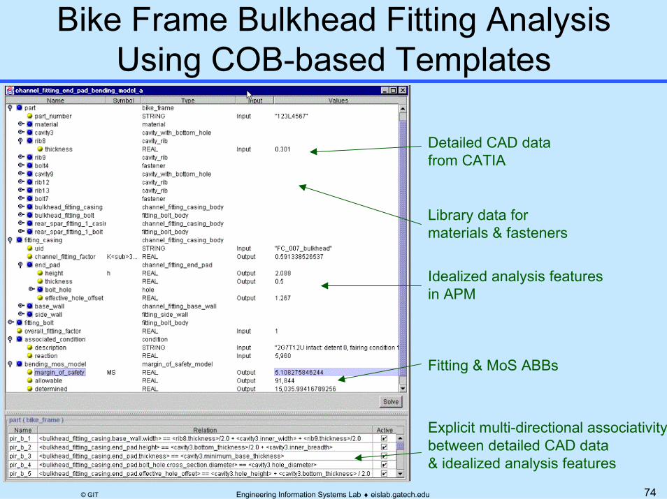
74Engineering Information Systems Lab ♦ eislab.gatech.edu© GIT
Detailed CAD datafrom CATIA
Idealized analysis features in APM
Explicit multi-directional associativity between detailed CAD data & idealized analysis features
Fitting & MoS ABBs
Library data for materials & fasteners

75Engineering Information Systems Lab ♦ eislab.gatech.edu© GIT
� Analysis Integration Challenges� Introduction to Constrained Objects (COBs)� Overview of COB-based XAI� Example Applications
� Electronic Packaging Thermomechanical Analysis� Aerospace Structural Analysis
� Optimization Integration� Summary

76Engineering Information Systems Lab ♦ eislab.gatech.edu© GIT
Mfg. CAD/CAM,Measurements
etc.
Conditions
MCAD
ECAD
Analysis Results
Ansys
Abaqus
CAE
Analysis Results
Ansys
Abaqus
CAE
Analysis Module Catalogs
SelectedAnalysis Module (CBAM)
AutomatedIdealization/
Defeaturization
Product Model
(work-in-process)
ImprovedDesign / Process
Optimization Module (OMEP)
CONMIN
DSIDES
X1
X2
Feasible Region
x xup2 ≤
x xlow ≤ 2
g x p1 0( , ) ≤
g x p2 0( , ) ≤
X1
X2
Feasible Region
x xup2 ≤
x xlow ≤ 2
g x p1 0( , ) ≤
g x p2 0( , ) ≤

77Engineering Information Systems Lab ♦ eislab.gatech.edu© GIT
Min Weight
g (x)<0h(x) =0
subject toStressDesign variablesArea
Min Weight
OPTIMIZATION MODEL CLASS
Optimization Object 1 Optimization Object 2
Min Weight
subject to
X(H)
Min Weight
subject to
X(H,LL,LR)
OPTIMIZATION MODEL CLASS
Optimization Object 1 Optimization Object 2
Min Weight, Cost
subject to
Optimization Object 3
X(H,LL,LR,Mat)
g (x)<0h(x) =0
g (x)<0h(x) =0
2D PLANE STRAIN MODEL
1D EXTENSIONAL STRESS MODEL
Analysis Model(s)Enhancement and/or Addition
subject toStressBucklingDesign variablesArea, Material
y
xPP
E, A
∆LLeff
ε=, σ=
L
Objective, design variable, and/or constraint function enhancement
78Engineering Information Systems Lab ♦ eislab.gatech.edu© GIT
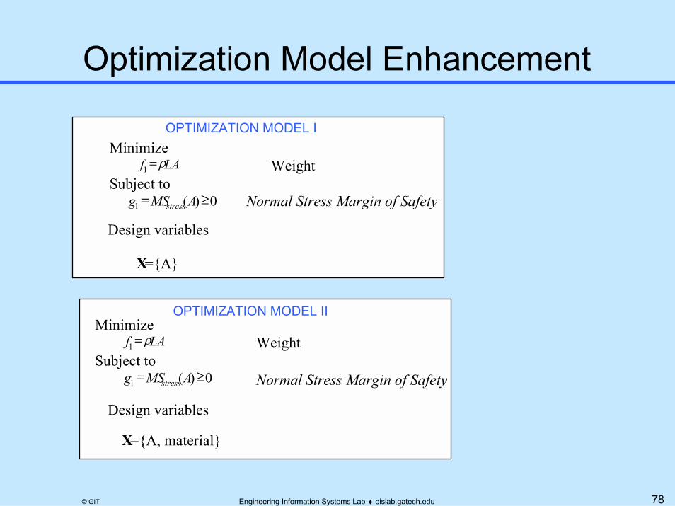
MinimizeLAf ρ=1 Weight
Subject to0)(1 ≥= AMSg stress Normal Stress Margin of Safety
Design variables
X={A}
MinimizeLAf ρ=1 Weight
Subject to0)(1 ≥= AMSg stress Normal Stress Margin of Safety
Design variables
X={A, material}
OPTIMIZATION MODEL I
OPTIMIZATION MODEL II
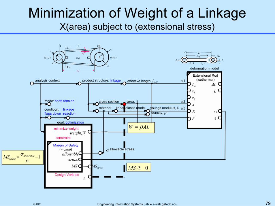
79Engineering Information Systems Lab ♦ eislab.gatech.edu© GIT
X(area) subject to (extensional stress)
Leff
product structure: linkage
material
effective length, Leff
deformation model
linear elastic model
Lo
Extensional Rod(isothermal)
F
∆L
σA
L
εE
x2
x1
youngs modulus, E
cross section area, A
al1
al3
al2
analysis context
goal: optimization
mode: shaft tension
condition: flaps down
linkage reaction
allowable stressMargin of Safety
(> case)allowable
actualMS
ts1
A
Sleeve 1
A ts2
ds2
ds1
Sleeve 2
L
Shaft
Leff
θs
y
xPP
E, A
∆LLeff
ε=, σ=
L
minimize weight
constraint
Design VariableA
weight,WW AL= ρ
MS ≥ 0
density, ρ
MSstress
σ1−=
σσ allowable
stressMS

80Engineering Information Systems Lab ♦ eislab.gatech.edu© GIT
X(area, material) subject to (extensional stress)
Leff
product structure: linkage
material
effective length, Leff
deformation model
linear elastic model
Lo
Extensional Rod(isothermal)
F
∆L
σA
L
εE
x2
x1
youngs modulus, E
cross section area, A
al1
al3
al2
analysis context
goal: optimization
mode: shaft tension
condition: flaps down
linkage reaction
allowable stressMargin of Safety
(> case)allowable
actualMS
ts1
A
Sleeve 1
A ts2
ds2
ds1
Sleeve 2
L
Shaft
Leff
θs
y
xPP
E, A
∆LLeff
ε=, σ=
L
minimize weight
constraint
Design Variablearea,A
weight,WW AL= ρ
MS ≥ 0
density, ρ
MSstress
σ1−=
σσ allowable
stressMS
material

81Engineering Information Systems Lab ♦ eislab.gatech.edu© GIT
MinimizeLAf ρ=1 Weight
Subject to0)(1 ≥= AMSg stress Normal Stress Margin of Safety
0)(2 ≥= AMSg buckling Buckling Margin of SafetyDesign variables
X={A}
MinimizeLAf ρ=1 Weight
Subject to0)(1 ≥= AMSg stress Normal Stress Margin of Safety
0)(2 ≥= AMSg buckling Buckling Margin of SafetyDesign variables
X={A, material}
OPTIMIZATION MODEL III
OPTIMIZATION MODEL IV
82Engineering Information Systems Lab ♦ eislab.gatech.edu© GIT
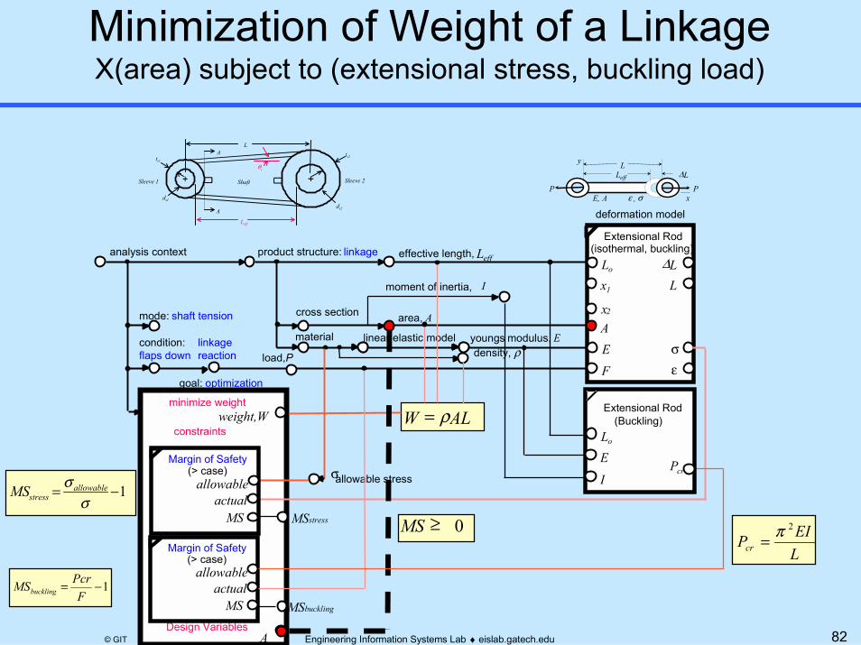
X(area) subject to (extensional stress, buckling load)
Leff
product structure: linkage
material
effective length, Leff
deformation model
linear elastic model
Lo
Extensional Rod(isothermal, buckling)
F
∆L
σA
L
εE
x2
x1
youngs modulus, E
cross section area, A
analysis context
goal: optimization
mode: shaft tension
condition: flaps down
linkage reaction
allowable stress
Margin of Safety(> case)
allowableactual
MS
ts1
A
Sleeve 1
A ts2
ds2
ds1
Sleeve 2
L
Shaft
Leff
θs
y
xPP
E, A
∆LLeff
ε=, σ=
L
minimize weight
constraints
Design VariablesA
weight,W W AL= ρ
MS ≥ 0MSstress
σ
Margin of Safety(> case)
allowableactual
MS
moment of inertia, I
LEIPcr
2π=
1−=σ
σ allowablestressMS
1−=F
PcrMSbuckling
load,P
MSbuckling
Lo
Extensional Rod(Buckling)
PcrIE
density, ρ

83Engineering Information Systems Lab ♦ eislab.gatech.edu© GIT
X(area, material) subject to (extensional stress, buckling load)
Leff
product structure: linkage
material
effective length, Leff
deformation model
linear elastic model
Lo
Extensional Rod(isothermal, buckling)
F
∆L
σA
L
εE
x2
x1
youngs modulus, E
cross section area, A
analysis context
goal: optimization
mode: shaft tension
condition: flaps down
linkage reaction
allowable stress
Margin of Safety(> case)
allowableactual
MS
ts1
A
Sleeve 1
A ts2
ds2
ds1
Sleeve 2
L
Shaft
Leff
θs
y
xPP
E, A
∆LLeff
ε=, σ=
L
minimize weight
constraints
Design Variables A
weight,W W AL= ρ
MS ≥ 0MSstress
σ
Margin of Safety(> case)
allowableactual
MS
moment of inertia, I
LEIPcr
2π=
1−=σ
σ allowablestressMS
1−=F
PcrMSbuckling
load,P
MSbuckling
Lo
Extensional Rod(Buckling)
PcrIE
density, ρ
material
84Engineering Information Systems Lab ♦ eislab.gatech.edu© GIT
� Analysis Integration Challenges� Introduction to Constrained Objects (COBs)� Overview of COB-based XAI� Example Applications
� Electronic Packaging Thermomechanical Analysis� Aerospace Structural Analysis
� Optimization Integration� Summary

85Engineering Information Systems Lab ♦ eislab.gatech.edu© GIT
� Emphasis on X-analysis integration (XAI) for design reuse (DAI,SBD)� Multi-Representation Architecture (MRA)
– Addressing fundamental XAI/DAI issues» Multi-fidelity, multi-directional, fine-grained associativity, etc.
– General methodology --> Flexibility & broad application� Research advances & applications
– Product data-driven analysis (STEP AP210, GenCAM, etc.)– Internet-based engineering service bureau (ESB) techniques– Object techniques for next-generation aerospace analysis systems– ~10:1 FEA modeling time reduction in pilot tests (chip packages)
� Tools and development services– Analysis integration toolkit: XaiTools Framework and applications– Pilot commercial ESB: U-Engineer.com– Company-tailored engineering information system solutions
� Motivated by industry & government collaboration

86Engineering Information Systems Lab ♦ eislab.gatech.edu© GIT
Selected Tools and Servicesoffered via Georgia Tech Research Corp.
http://eislab.gatech.edu/
� XaiTools Framework™
– General-purpose analysis integration toolkit� Product-Specific Toolkits
– XaiTools PWA-B™
– XaiTools ChipPackage™
� U-Engineer.com™
– Internet-based engineering service bureau (ESB)– Self-serve automated analysis modules ↔ Full-serve consulting
� Research, Development, and Consulting– Analysis integration & optimization– Product-specific analysis module catalogs– Internet-based ESB development– Engineering information technology
» PDM, STEP, GenCAM, XML, UML, Java, CORBA, Internet, …

87Engineering Information Systems Lab ♦ eislab.gatech.edu© GIT
� EIS Lab web site: http://eislab.gatech.edu/– Publications, project overviews, tools, etc.– See Publications, DAI/XAI, Suggested Starting Points
� XaiTools home page: http://eislab.gatech.edu/tools/XaiTools/
� Pilot commercial ESB: http://www.u-engineer.com/– Internet-based self-serve analysis– Analysis module catalog for electronic packaging– Highly automated front-ends to general FEA & math tools