generic esb monitoring architecture compliant with jbi
DESCRIPTION
Currently, the significance of the Enterprise Application Integration (EAI) in the field of Service Oriented Architecture (SOA) is gradually increasing. The quality of the integration patterns is constantly ameliorating. Progressive integration solutions are designed, published and offered to the community by most of the prominent IT vendors. Today, Enterprise Service Bus (ESB) is one of the most meaningful solutions and top-selling products on the market of the integration services. There is, however, no agreed-upon definition of what an ESB actually is. Java Business Integration (JBI) presents an approach to standardizing the ESB pattern by specifying a concrete, well-defined and Java-centric model of ESB. The first version of the specification does not mention any kind of monitoring solution for JBI, which is the vital drawback of the concept. Increasing complexity of the SOA-oriented IT systems implies higher importance of the selective monitoring, which allows to mitigate the problem of the management of software infrastructure. The main goal of the thesis is to design and implement a system which adds a monitoring and management logic to a Java Business Integration container in such a way that the logic is fully transparent and compliant with the JBI specification and allows to gather, process and expose sophisticated information regarding the qualitative parameters and operational reliability of the JBI container. The design of the system was performed in accordance with the Experimental Driven Development (EDD) methodology. At the beginning a statement of functional and non-functional requirements was created. Afterwards, an analysis and prototype construction were performed. At the end, the prototype was meticulously examined during a set of experiments which were conducted, in order to provide best-fitting architectural solutions which are compliant with the aforementioned requirements. Finally, it was possible to design and implement functional and innovative realization of the JBI monitoring solution called GlassBus. Performance test have proofed that the average JBI performance deterioration, while being monitored, is not higher than 20 percent. Not only did the results of the work described in this thesis fully satisfy the authors, but they also amazed the academic supervisor. Progressive architectural solutions introduced in GlassBus ensure its forthcoming success.TRANSCRIPT

Generic ESB Monitoring Architecture Compliant With JBI
Marek PsiukTomasz Bujok
Supervisor: Prof. Krzysztof Zielinski
Department of Electrical Engineering, Automatics,Computer Science and Electronics
AGH University of Science and Technology, Krakow, Poland
Thesis submitted for the Degree of Master of Computer Science inAGH University of Science and Technology
· 2008 ·

Uniwersalna architektura monitoringu ESBzgodna ze specyfikacja JBI
Marek PsiukTomasz Bujok
Promotor: prof. dr hab. inz. Krzysztof Zielinski
Wydział Elektrotechniki, Automatyki,Informatyki i Elektroniki
Akademia Gorniczo Hutnicza, Krakow, Polska
Praca MagisterskaAkademia Gorniczno Hutnicza
· 2008 ·
”SOA will be used in more than 50 percent of newmission-critical operational applications and businessprocesses designed in 2007 and in more than 80 percent by2010”
Gartner Raport, 2007
Abstract
Currently, the significance of the Enterprise Application Integration (EAI) in the field of Service OrientedArchitecture (SOA) is gradually increasing. The quality of the integration patterns is constantly amelio-rating. Progressive integration solutions are designed, published and offered to the community by most ofthe prominent IT vendors. Today, Enterprise Service Bus (ESB) is one of the most meaningful solutionsand top-selling products on the market of the integration services. There is, however, no agreed-upon def-inition of what an ESB actually is. Java Business Integration (JBI) presents an approach to standardizingthe ESB pattern by specifying a concrete, well-defined and Java-centric model of ESB. The first versionof the specification does not mention any kind of monitoring solution for JBI, which is the vital drawbackof the concept. Increasing complexity of the SOA-oriented IT systems implies higher importance of theselective monitoring, which allows to mitigate the problem of the management of software infrastructure.The main goal of the thesis is to design and implement a system which adds a monitoring and manage-ment logic to a Java Business Integration container in such a way that the logic is fully transparent andcompliant with the JBI specification and allows to gather, process and expose sophisticated informationregarding the qualitative parameters and operational reliability of the JBI container. The design of thesystem was performed in accordance with the Experimental Driven Development (EDD) methodology.At the beginning a statement of functional and non-functional requirements was created. Afterwards,an analysis and prototype construction were performed. At the end, the prototype was meticulously ex-amined during a set of experiments which were conducted, in order to provide best-fitting architecturalsolutions which are compliant with the aforementioned requirements. Finally, it was possible to designand implement functional and innovative realization of the JBI monitoring solution called GlassBus.Performance test have proofed that the average JBI performance deterioration, while being monitored, isnot higher than 20 percent. Not only did the results of the work described in this thesis fully satisfy theauthors, but they also amazed the academic supervisor. Progressive architectural solutions introduced inGlassBus ensure its forthcoming success.

Contents
Abstract i
Declaration ix
Acknowledgements x
1 Introduction 11.1 Enterprise Application Integration . . . . . . . . . . . . . . . . . . . . . . . . . . . . 11.2 Enterprise Service Bus . . . . . . . . . . . . . . . . . . . . . . . . . . . . . . . . . . . 11.3 Java Business Integration . . . . . . . . . . . . . . . . . . . . . . . . . . . . . . . . . . 21.4 Monitoring . . . . . . . . . . . . . . . . . . . . . . . . . . . . . . . . . . . . . . . . . . 21.5 Thesis statement . . . . . . . . . . . . . . . . . . . . . . . . . . . . . . . . . . . . . . . 21.6 Research contribution . . . . . . . . . . . . . . . . . . . . . . . . . . . . . . . . . . . . 21.7 Organization of thesis . . . . . . . . . . . . . . . . . . . . . . . . . . . . . . . . . . . 3
2 Enterprise Integration Theory 42.1 Preamble . . . . . . . . . . . . . . . . . . . . . . . . . . . . . . . . . . . . . . . . . . . 42.2 Definition of the Enterprise Application Integration . . . . . . . . . . . . . . . . . . 4
2.2.1 Reason for integration . . . . . . . . . . . . . . . . . . . . . . . . . . . . . . . 52.2.2 Challenge . . . . . . . . . . . . . . . . . . . . . . . . . . . . . . . . . . . . . . 62.2.3 Integration taxonomy . . . . . . . . . . . . . . . . . . . . . . . . . . . . . . . 62.2.4 Integration factors . . . . . . . . . . . . . . . . . . . . . . . . . . . . . . . . . 7
2.3 Enterprise Integration Patterns . . . . . . . . . . . . . . . . . . . . . . . . . . . . . . 82.3.1 Topologies Fundamentals . . . . . . . . . . . . . . . . . . . . . . . . . . . . . 82.3.2 Integration Fundamentals . . . . . . . . . . . . . . . . . . . . . . . . . . . . . 82.3.3 Properties of integration solutions . . . . . . . . . . . . . . . . . . . . . . . . 92.3.4 Point to point Integration . . . . . . . . . . . . . . . . . . . . . . . . . . . . . 102.3.5 Broker Integration . . . . . . . . . . . . . . . . . . . . . . . . . . . . . . . . . 112.3.6 Message Bus Integration . . . . . . . . . . . . . . . . . . . . . . . . . . . . . . 162.3.7 Comparison . . . . . . . . . . . . . . . . . . . . . . . . . . . . . . . . . . . . . 19
2.4 Enterprise Service Bus . . . . . . . . . . . . . . . . . . . . . . . . . . . . . . . . . . . 202.4.1 Service Oriented Architecture as ESB environment. . . . . . . . . . . . . . . 212.4.2 ESB Definition . . . . . . . . . . . . . . . . . . . . . . . . . . . . . . . . . . . . 22
ii
Contents
2.4.3 ESB implementations . . . . . . . . . . . . . . . . . . . . . . . . . . . . . . . . 252.4.4 Summary . . . . . . . . . . . . . . . . . . . . . . . . . . . . . . . . . . . . . . 25
2.5 Java Business Integration . . . . . . . . . . . . . . . . . . . . . . . . . . . . . . . . . . 262.5.1 Background . . . . . . . . . . . . . . . . . . . . . . . . . . . . . . . . . . . . . 262.5.2 Architecture . . . . . . . . . . . . . . . . . . . . . . . . . . . . . . . . . . . . . 272.5.3 JBI Implementations . . . . . . . . . . . . . . . . . . . . . . . . . . . . . . . . 322.5.4 Summary . . . . . . . . . . . . . . . . . . . . . . . . . . . . . . . . . . . . . . 33
2.6 Conclusion . . . . . . . . . . . . . . . . . . . . . . . . . . . . . . . . . . . . . . . . . . 33
3 JBI Monitoring 353.1 Preamble . . . . . . . . . . . . . . . . . . . . . . . . . . . . . . . . . . . . . . . . . . . 353.2 Monitoring abstraction . . . . . . . . . . . . . . . . . . . . . . . . . . . . . . . . . . . 353.3 JBI monitoring status quo . . . . . . . . . . . . . . . . . . . . . . . . . . . . . . . . . 37
3.3.1 Monitoring from JSR . . . . . . . . . . . . . . . . . . . . . . . . . . . . . . . . 373.3.2 ServiceMix monitoring . . . . . . . . . . . . . . . . . . . . . . . . . . . . . . . 393.3.3 OpenESB monitoring . . . . . . . . . . . . . . . . . . . . . . . . . . . . . . . . 413.3.4 Clustering . . . . . . . . . . . . . . . . . . . . . . . . . . . . . . . . . . . . . . 453.3.5 Status quo implications . . . . . . . . . . . . . . . . . . . . . . . . . . . . . . 49
3.4 Application monitoring theory . . . . . . . . . . . . . . . . . . . . . . . . . . . . . . 503.4.1 Application Response Measurement . . . . . . . . . . . . . . . . . . . . . . . 503.4.2 Business Activity Monitoring . . . . . . . . . . . . . . . . . . . . . . . . . . . 55
3.5 JBI Monitoring Challenge . . . . . . . . . . . . . . . . . . . . . . . . . . . . . . . . . 593.5.1 JBI context influence . . . . . . . . . . . . . . . . . . . . . . . . . . . . . . . . 593.5.2 Application theory influence . . . . . . . . . . . . . . . . . . . . . . . . . . . 61
3.6 Conclusion . . . . . . . . . . . . . . . . . . . . . . . . . . . . . . . . . . . . . . . . . . 64
4 Executive summary of the monitoring architecture 664.1 Preamble . . . . . . . . . . . . . . . . . . . . . . . . . . . . . . . . . . . . . . . . . . . 664.2 Problem definition . . . . . . . . . . . . . . . . . . . . . . . . . . . . . . . . . . . . . 66
4.2.1 Non-functional requirements . . . . . . . . . . . . . . . . . . . . . . . . . . . 674.2.2 Functional requirements . . . . . . . . . . . . . . . . . . . . . . . . . . . . . . 69
4.3 Introducing GlassBus . . . . . . . . . . . . . . . . . . . . . . . . . . . . . . . . . . . . 714.4 Monitoring Abstraction . . . . . . . . . . . . . . . . . . . . . . . . . . . . . . . . . . 724.5 Conclusion . . . . . . . . . . . . . . . . . . . . . . . . . . . . . . . . . . . . . . . . . . 77
5 GlassBus Research 795.1 Preamble . . . . . . . . . . . . . . . . . . . . . . . . . . . . . . . . . . . . . . . . . . . 795.2 Experiments placement . . . . . . . . . . . . . . . . . . . . . . . . . . . . . . . . . . . 805.3 Information acquiring mechanism . . . . . . . . . . . . . . . . . . . . . . . . . . . . 81
5.3.1 Possible options . . . . . . . . . . . . . . . . . . . . . . . . . . . . . . . . . . . 815.3.2 Realisation . . . . . . . . . . . . . . . . . . . . . . . . . . . . . . . . . . . . . . 82
5.4 JBI monitoring mechanisms . . . . . . . . . . . . . . . . . . . . . . . . . . . . . . . . 835.4.1 Monitoring information . . . . . . . . . . . . . . . . . . . . . . . . . . . . . . 83
5.5 Correlation heuristics . . . . . . . . . . . . . . . . . . . . . . . . . . . . . . . . . . . . 875.5.1 Problem definition . . . . . . . . . . . . . . . . . . . . . . . . . . . . . . . . . 885.5.2 Realization . . . . . . . . . . . . . . . . . . . . . . . . . . . . . . . . . . . . . . 89
iii
Contents
5.6 Persistence . . . . . . . . . . . . . . . . . . . . . . . . . . . . . . . . . . . . . . . . . . 945.6.1 Database choice . . . . . . . . . . . . . . . . . . . . . . . . . . . . . . . . . . . 955.6.2 Persistence abstraction . . . . . . . . . . . . . . . . . . . . . . . . . . . . . . . 96
5.7 Communication middleware . . . . . . . . . . . . . . . . . . . . . . . . . . . . . . . 995.7.1 Communication theory . . . . . . . . . . . . . . . . . . . . . . . . . . . . . . 995.7.2 MOM Implementation provider . . . . . . . . . . . . . . . . . . . . . . . . . 1035.7.3 JMS Sender . . . . . . . . . . . . . . . . . . . . . . . . . . . . . . . . . . . . . 1105.7.4 JMS Receiver . . . . . . . . . . . . . . . . . . . . . . . . . . . . . . . . . . . . 1125.7.5 Communication security . . . . . . . . . . . . . . . . . . . . . . . . . . . . . . 116
5.8 Management middleware . . . . . . . . . . . . . . . . . . . . . . . . . . . . . . . . . 1175.8.1 Possible options . . . . . . . . . . . . . . . . . . . . . . . . . . . . . . . . . . . 1175.8.2 Realisation . . . . . . . . . . . . . . . . . . . . . . . . . . . . . . . . . . . . . . 118
5.9 Hierarchical Data Management . . . . . . . . . . . . . . . . . . . . . . . . . . . . . . 1205.9.1 Possible solutions . . . . . . . . . . . . . . . . . . . . . . . . . . . . . . . . . . 1205.9.2 Realization . . . . . . . . . . . . . . . . . . . . . . . . . . . . . . . . . . . . . . 121
5.10 Installation and runtime environments . . . . . . . . . . . . . . . . . . . . . . . . . . 1225.10.1 Deployment assumptions . . . . . . . . . . . . . . . . . . . . . . . . . . . . . 1225.10.2 Deployment scenarios . . . . . . . . . . . . . . . . . . . . . . . . . . . . . . . 1235.10.3 Realization . . . . . . . . . . . . . . . . . . . . . . . . . . . . . . . . . . . . . . 125
5.11 Monitoring interface . . . . . . . . . . . . . . . . . . . . . . . . . . . . . . . . . . . . 1265.11.1 Possible solutions . . . . . . . . . . . . . . . . . . . . . . . . . . . . . . . . . . 1265.11.2 Realization . . . . . . . . . . . . . . . . . . . . . . . . . . . . . . . . . . . . . . 127
5.12 Logging . . . . . . . . . . . . . . . . . . . . . . . . . . . . . . . . . . . . . . . . . . . . 1285.12.1 Possible options . . . . . . . . . . . . . . . . . . . . . . . . . . . . . . . . . . . 1295.12.2 Realization . . . . . . . . . . . . . . . . . . . . . . . . . . . . . . . . . . . . . . 130
5.13 Conclusion . . . . . . . . . . . . . . . . . . . . . . . . . . . . . . . . . . . . . . . . . . 131
6 GlassBus Implementation 1336.1 Preamble . . . . . . . . . . . . . . . . . . . . . . . . . . . . . . . . . . . . . . . . . . . 1336.2 Architecture Overview . . . . . . . . . . . . . . . . . . . . . . . . . . . . . . . . . . . 1346.3 Logical Structure . . . . . . . . . . . . . . . . . . . . . . . . . . . . . . . . . . . . . . 136
6.3.1 Domain model . . . . . . . . . . . . . . . . . . . . . . . . . . . . . . . . . . . 1366.3.2 GlassBus Agent . . . . . . . . . . . . . . . . . . . . . . . . . . . . . . . . . . . 1406.3.3 GlassBus Engine . . . . . . . . . . . . . . . . . . . . . . . . . . . . . . . . . . 1436.3.4 External interface model . . . . . . . . . . . . . . . . . . . . . . . . . . . . . . 1446.3.5 Management and selectivity model . . . . . . . . . . . . . . . . . . . . . . . 1506.3.6 Invocation flows . . . . . . . . . . . . . . . . . . . . . . . . . . . . . . . . . . 152
6.4 Physical Structure . . . . . . . . . . . . . . . . . . . . . . . . . . . . . . . . . . . . . . 1556.5 Configuration . . . . . . . . . . . . . . . . . . . . . . . . . . . . . . . . . . . . . . . . 1576.6 Installation . . . . . . . . . . . . . . . . . . . . . . . . . . . . . . . . . . . . . . . . . . 1596.7 Implementation status . . . . . . . . . . . . . . . . . . . . . . . . . . . . . . . . . . . 1606.8 Performance Tests . . . . . . . . . . . . . . . . . . . . . . . . . . . . . . . . . . . . . . 160
6.8.1 Test environment . . . . . . . . . . . . . . . . . . . . . . . . . . . . . . . . . . 1616.8.2 ServiceMix . . . . . . . . . . . . . . . . . . . . . . . . . . . . . . . . . . . . . . 1626.8.3 OpenESB . . . . . . . . . . . . . . . . . . . . . . . . . . . . . . . . . . . . . . . 163
iv

Contents
6.8.4 Summary . . . . . . . . . . . . . . . . . . . . . . . . . . . . . . . . . . . . . . 1646.9 Conclusion . . . . . . . . . . . . . . . . . . . . . . . . . . . . . . . . . . . . . . . . . . 165
7 Conclusions 1667.1 Overview . . . . . . . . . . . . . . . . . . . . . . . . . . . . . . . . . . . . . . . . . . . 1667.2 The status of Java Business Integration . . . . . . . . . . . . . . . . . . . . . . . . . . 1677.3 Future of JSR-208 - JBI 2.0 . . . . . . . . . . . . . . . . . . . . . . . . . . . . . . . . . 1677.4 GlassBus achievement . . . . . . . . . . . . . . . . . . . . . . . . . . . . . . . . . . . 169
Appendices 171
A Source code 172
Bibliography 186
v
List of Figures
2.1 Integration scopes . . . . . . . . . . . . . . . . . . . . . . . . . . . . . . . . . . . . . . 62.2 Point to point integration . . . . . . . . . . . . . . . . . . . . . . . . . . . . . . . . . . 102.3 Broker integration . . . . . . . . . . . . . . . . . . . . . . . . . . . . . . . . . . . . . . 122.4 Classes of brokers . . . . . . . . . . . . . . . . . . . . . . . . . . . . . . . . . . . . . . 132.5 Direct Broker Sequence Diagram . . . . . . . . . . . . . . . . . . . . . . . . . . . . . 142.6 Indirect Broker Sequence Diagram . . . . . . . . . . . . . . . . . . . . . . . . . . . . 142.7 Bus integration . . . . . . . . . . . . . . . . . . . . . . . . . . . . . . . . . . . . . . . 162.8 Topology Summary . . . . . . . . . . . . . . . . . . . . . . . . . . . . . . . . . . . . . 192.9 Location of ESB in SOA environment . . . . . . . . . . . . . . . . . . . . . . . . . . . 212.10 Architecture of JBI . . . . . . . . . . . . . . . . . . . . . . . . . . . . . . . . . . . . . . 272.11 JBI Messaging Model . . . . . . . . . . . . . . . . . . . . . . . . . . . . . . . . . . . . 282.12 Message Exchange Flow . . . . . . . . . . . . . . . . . . . . . . . . . . . . . . . . . . 31
3.1 ServiceMix clustering . . . . . . . . . . . . . . . . . . . . . . . . . . . . . . . . . . . . 463.2 OpenESB clustering . . . . . . . . . . . . . . . . . . . . . . . . . . . . . . . . . . . . . 483.3 Application invokes methods on ArmTransaction . . . . . . . . . . . . . . . . . . . 513.4 Connection between ARM Interface and Agent . . . . . . . . . . . . . . . . . . . . . 513.5 Sample distributed system . . . . . . . . . . . . . . . . . . . . . . . . . . . . . . . . . 523.6 Transaction and parent-child correlators . . . . . . . . . . . . . . . . . . . . . . . . . 523.7 Message Oriented Middleware ARM patterns . . . . . . . . . . . . . . . . . . . . . 533.8 Business process management life-cycle . . . . . . . . . . . . . . . . . . . . . . . . . 563.9 CEP-oriented BAM architecture . . . . . . . . . . . . . . . . . . . . . . . . . . . . . . 633.10 Possible Architecture Positioning . . . . . . . . . . . . . . . . . . . . . . . . . . . . . 64
4.1 GlassBus architecture overview . . . . . . . . . . . . . . . . . . . . . . . . . . . . . . 724.2 ME FLOW PATTERN example . . . . . . . . . . . . . . . . . . . . . . . . . . . . . . 744.3 ME SUB FLOW PATTERN example . . . . . . . . . . . . . . . . . . . . . . . . . . . 744.4 ME TRANS example nr.1 . . . . . . . . . . . . . . . . . . . . . . . . . . . . . . . . . 754.5 ME TRANS example nr.2 . . . . . . . . . . . . . . . . . . . . . . . . . . . . . . . . . 764.6 BUSS TRANS PATTERN example . . . . . . . . . . . . . . . . . . . . . . . . . . . . 77
5.1 GlassBus architecture overview - placement of the experiments . . . . . . . . . . . 80
vi
List of Figures
5.2 Message correlation algorithm overview . . . . . . . . . . . . . . . . . . . . . . . . . 905.3 ActiveMQ Broker Topology . . . . . . . . . . . . . . . . . . . . . . . . . . . . . . . . 1045.4 Out-of-the-box scenario . . . . . . . . . . . . . . . . . . . . . . . . . . . . . . . . . . 1085.5 Distributed scenario . . . . . . . . . . . . . . . . . . . . . . . . . . . . . . . . . . . . 1095.6 Engine broker clustering . . . . . . . . . . . . . . . . . . . . . . . . . . . . . . . . . . 1105.7 Message Driven Pojos architecture . . . . . . . . . . . . . . . . . . . . . . . . . . . . 1135.8 GlassBus deployment to Single monolithic bus . . . . . . . . . . . . . . . . . . . . . 1235.9 GlassBus single out-of-the-box deployment . . . . . . . . . . . . . . . . . . . . . . . 124
6.1 GlassBus complete architecture . . . . . . . . . . . . . . . . . . . . . . . . . . . . . . 1356.2 General logical structure . . . . . . . . . . . . . . . . . . . . . . . . . . . . . . . . . . 1366.3 JBI Topology . . . . . . . . . . . . . . . . . . . . . . . . . . . . . . . . . . . . . . . . . 1376.4 JBI Message Exchange Patterns . . . . . . . . . . . . . . . . . . . . . . . . . . . . . . 1386.5 GlassBus Dao . . . . . . . . . . . . . . . . . . . . . . . . . . . . . . . . . . . . . . . . 1406.6 GlassBus Agent . . . . . . . . . . . . . . . . . . . . . . . . . . . . . . . . . . . . . . . 1416.7 GlassBus Engine . . . . . . . . . . . . . . . . . . . . . . . . . . . . . . . . . . . . . . . 1436.8 External monitoring interface . . . . . . . . . . . . . . . . . . . . . . . . . . . . . . . 1466.9 The Agent in the Engine registration sequence diagram . . . . . . . . . . . . . . . . 1536.10 Messaging propagation sequence diagram . . . . . . . . . . . . . . . . . . . . . . . 1546.11 Topology propagation sequence diagram . . . . . . . . . . . . . . . . . . . . . . . . 1556.12 Physical structure of GlassBus implementation . . . . . . . . . . . . . . . . . . . . . 1566.13 ServiceMix topology for performance tests . . . . . . . . . . . . . . . . . . . . . . . 1626.14 OpenESB topology for performance tests . . . . . . . . . . . . . . . . . . . . . . . . 1636.15 Comparison of GlassBus performance overhead . . . . . . . . . . . . . . . . . . . . 164
vii
List of Tables
2.1 Topologies comparison . . . . . . . . . . . . . . . . . . . . . . . . . . . . . . . . . . . 202.2 JBI implementations . . . . . . . . . . . . . . . . . . . . . . . . . . . . . . . . . . . . 32
3.1 Clustering comparison . . . . . . . . . . . . . . . . . . . . . . . . . . . . . . . . . . . 493.2 JBI implementations comparison . . . . . . . . . . . . . . . . . . . . . . . . . . . . . 493.3 Abstraction contextual evaluation . . . . . . . . . . . . . . . . . . . . . . . . . . . . 61
5.1 AOP Requirement compliance . . . . . . . . . . . . . . . . . . . . . . . . . . . . . . 835.2 JBI parameters requirement compliance . . . . . . . . . . . . . . . . . . . . . . . . . 875.3 JBI parameters requirement compliance . . . . . . . . . . . . . . . . . . . . . . . . . 945.4 Persistence Requirement compliance . . . . . . . . . . . . . . . . . . . . . . . . . . . 995.5 Tight vs. Loose coupling discussion . . . . . . . . . . . . . . . . . . . . . . . . . . . 1015.6 Communication middleware comparison . . . . . . . . . . . . . . . . . . . . . . . . 1025.7 Basic comparison of the middleware performance . . . . . . . . . . . . . . . . . . . 1035.8 ActiveMQ performance comparison - embedded brokers . . . . . . . . . . . . . . . 1075.9 ActiveMQ performance comparison - embedded and remote brokers . . . . . . . . 1085.10 JMS sender performance comparison . . . . . . . . . . . . . . . . . . . . . . . . . . . 1115.11 JMS transmission reliability . . . . . . . . . . . . . . . . . . . . . . . . . . . . . . . . 1145.12 Communication middleware - requirement compliance . . . . . . . . . . . . . . . . 1165.13 Management requirement compliance . . . . . . . . . . . . . . . . . . . . . . . . . . 1195.14 Hierarchical data - requirement compliance . . . . . . . . . . . . . . . . . . . . . . . 1225.15 Deployment Requirement compliance . . . . . . . . . . . . . . . . . . . . . . . . . . 1265.16 Monitoring interface - requirement compliance . . . . . . . . . . . . . . . . . . . . . 1285.17 Logging Requirement compliance . . . . . . . . . . . . . . . . . . . . . . . . . . . . 131
6.1 Timing path - MEP relations . . . . . . . . . . . . . . . . . . . . . . . . . . . . . . . . 1396.2 Performance of glazed ServiceMix . . . . . . . . . . . . . . . . . . . . . . . . . . . . 1626.3 GlassBus overhead in ServiceMix . . . . . . . . . . . . . . . . . . . . . . . . . . . . . 1636.4 Performance of glazed OpenESB . . . . . . . . . . . . . . . . . . . . . . . . . . . . . 1636.5 GlassBus overhead in OpenESB . . . . . . . . . . . . . . . . . . . . . . . . . . . . . . 163
7.1 GlassBus effort perspective . . . . . . . . . . . . . . . . . . . . . . . . . . . . . . . . 1697.2 Proof-of-Concept projects effort perspective . . . . . . . . . . . . . . . . . . . . . . . 169
viii

Declaration
The work in this thesis is based on the research carried out at the Department of Electrical En-gineering, Automatics, Computer Science and Electronics of the AGH University of Science andTechnology in Krakow, Poland. No part of this thesis has been submitted elsewhere for any otherdegree or qualification and it is all our own work unless referenced to the contrary in the text. Ithas to be admitted that all work enclosed in the thesis is the result of a joint and collective researchconducted and approved by both of the authors. Organization of the thesis as well as the outlineand content of the chapters were also agreed upon. It has to be mentioned, however, which partof the text describing the aforementioned research, is the individual contribution of each author:
• Tomasz Bujok wrote Chapters 1, 2, 4 and the following Sections of Chapter 5 : 5.1, 5.2, 5.5(without 5.5.2), 5.7, 5.9, 5.11.
• Marek Psiuk wrote Chapters 3, 6, 7 and the following Sections of Chapter 5 : 5.3, 5.4, 5.5.2,5.6, 5.8, 5.10, 5.12, 5.13.
Copyright c© 2008 by Tomasz Bujok and Marek Psiuk.“The copyright of this thesis rests with the authors. No quotations from it should be publishedwithout the authors’ prior written consent and information derived from it should be acknowl-edged”.
ix

Acknowledgments
First of all, we would like to express our sincere gratitude and appreciation to our thesis advisor,Prof. Krzysztof Zielinski, for his continuous inspiration, encouragement, patience and carefulguidance during our study years. He gave us the opportunity to minutely consider the problemsof IT and he taught us how to meticulously analyze them from different perspectives. He has alsoshown a great and consistent interest in our project during its design and development whichgreatly refined its quality.
We would also like to thank our families for the guidance, support and love they provided uswith in particular through the work on the thesis, without whom we would not have finished.
In conclusion, we would like to express our gratitude to Magdalena Gawłowska-Bujok and KatarzynaHussar for an indispensable and thorough proofreading.
Tomasz Bujok, Marek PsiukKrakow, Poland
September 9, 2008
x
Chapter 1
Introduction
We are what we repeatedly do. Excellence, then, is not an act, but a habit. Aristotle, Ancient GreekPhilosopher, Scientist and Physician.
This chapter briefly introduces the basic terms and concepts of the Enterprise Application Integration,Enterprise Service Bus as well as Java Business Integration. It also explains the importance of monitoring,which is a key aspect of every modern enterprise system. This chapter also presents the goals and mainassumptions of the thesis.
1.1 Enterprise Application Integration
Today, enterprises are facing numerous challenging problems induced by development of theglobal village and the Internet itself. On the one hand, company customers constantly demandreal-time service, better performance, higher quality and lower prices. On the other hand, themarket is constantly undergoing dynamic changes to which companies have to react, which cre-ates competitive growth. The strategy of sustainable development makes the companies becomemore agile in the sense of ability to react to the requirements that rapidly alter and demands ofthe environment. One of the most important relations which have to be shaped by an efficientlyoperated company, whose quality cannot deteriorate during the organization’s evolution, are:
• B2B - Business to Business - a set of relations between specified business and cooperatingbusinesses.
• B2C - Business to Consumer - a set of relations between specified business and a consumer.
Business agility is mostly dependent on business infrastructure. In addition, the infrastructuredetermines the agility of the business as this very infrastructure has to provide the company withthe possibility of implementing new business processes through the integration and cooperationbetween existing ones. All these modifications have to be implemented as fast and efficiently aspossible, which reduces business costs. The explained process of Enterprise Integration has to beperformed at the level of computer applications which is a core of every modern organization.
1.2 Enterprise Service Bus
”In computing, an enterprise service bus (ESB) refers to a software architecture construct. Thisconstruct is typically implemented by technologies found in a category of middleware infras-tructure products, usually based on recognized standards which provide fundamental servicesfor more complex architectures via an event-driven and standards-based messaging engine (the
1.3. Java Business Integration 2
bus)” [1]. What is very interesting, this definition of ESB by Wikipedia is only one of the widevariety of explanations. There is no agreement on what ESB actually is in the enterprise commu-nity. The majority says that it is an Enterprise Application Integration instrument. All of thesematters mentioned here are thoroughly investigated in what follows.
1.3 Java Business Integration
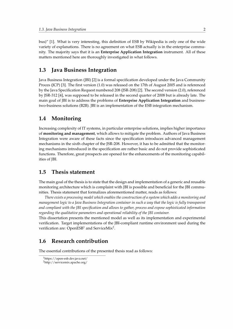
Java Business Integration (JBI) [2] is a formal specification developed under the Java CommunityProces (JCP) [3]. The first version (1.0) was released on the 17th of August 2005 and is referencedby the Java Specification Request numbered 208 (JSR-208) [2]. The second version (2.0), referencedby JSR-312 [4], was supposed to be released in the second quarter of 2008 but is already late. Themain goal of JBI is to address the problems of Enterprise Application Integration and business-two-business solutions (B2B). JBI is an implementation of the ESB integration mechanism.
1.4 Monitoring
Increasing complexity of IT systems, in particular enterprise solutions, implies higher importanceof monitoring and management, which allows to mitigate the problem. Authors of Java BusinessIntegration were aware of these facts since the specification introduces advanced managementmechanisms in the sixth chapter of the JSR-208. However, it has to be admitted that the monitor-ing mechanisms introduced in the specification are rather basic and do not provide sophisticatedfunctions. Therefore, great prospects are opened for the enhancements of the monitoring capabil-ities of JBI.
1.5 Thesis statement
The main goal of the thesis is to state that the design and implementation of a generic and reusablemonitoring architecture which is complaint with JBI is possible and beneficial for the JBI commu-nities. Thesis statement that formalizes aforementioned matter, reads as follows:
There exists a processing model which enables the construction of a system which adds a monitoring andmanagement logic to a Java Business Integration container in such a way that the logic is fully transparentand compliant with the JBI specification and allows to gather, process and expose sophisticated informationregarding the qualitative parameters and operational reliability of the JBI container.This dissertation presents the mentioned model as well as its implementation and experimentalverification. Target implementations of the JBI-compliant runtime environment used during theverification are: OpenESB1 and ServiceMix2.
1.6 Research contribution
The essential contributions of the presented thesis read as follows:
1https://open-esb.dev.java.net/2http://servicemix.apache.org/
1.7. Organization of thesis 3
• Theoretical model - general assumptions on the transparent JBI monitoring model basedon the Aspect Oriented Programming3 and Message Oriented Middleware3. Theoreticalapproach is also based on Application Response Measurement3 as well as Business Appli-cation Monitoring3.
• Concrete architecture - specification of a concrete JBI monitoring architecture based on theaforementioned theoretical model.
• Proof of concept - implementation of the JBI monitoring mechanism based on the concretearchitecture.
• Evaluation - performance and usability tests run in distributed JBI environment.
1.7 Organization of thesis
This thesis is organized in the following way:
• Chapter 2 overviews the existing application integration technologies presenting completebackground of ESB and JBI technologies. At the end, precise definition of these concepts ispresented in order to provide a clear view of the domain of the thesis.
• Chapter 3 examines the taxonomy of monitoring systems. It also contains the status quo ofthe JBI monitoring on the basis of JSR-208 specification as well as OpenESB and SerivceMixproprietary solutions. At the end, an overview of some helpful monitoring solutions isprovided.
• Chapter 4 presents the executive summary of the monitoring architecture in form of thefunctional and non-functional requirements. It also thoroughly explains the notions andconcepts introduced by the final solution - called GlassBus.
• Chapter 5 concisely formulates the results of experimental driven development carried outin order to choose the best fitting architectural solutions for GlassBus.
• Chapter 6 describes the architecture and implementation of GlassBus. It forms a completedevelopment documentation of the project. Results of the performance tests are enclosed atthe end of the chapter.
• Chapter 7 summarizes the conclusions and reflections concerning final solution and futureworks in the field of JBI.
3The concept is precisely explained in the following chapters.
Chapter 2
Enterprise Integration Theory
”Always design a thing by considering it in its next larger context a chair in a room, a room in a house, ahouse in an environment, an environment in a city plan.” Eliel Saarinen, a Finnish-American architectand city planner.
2.1 Preamble
The main goal of this chapter is to meticulously outline the domain of the thesis.At the beginning, the general idea of Enterprise Application Integration is presented. The section
contains an explanation of integration reasons, challenges as well as integration taxonomy which helps tosummarize all factors regarding application integration. The main emphasis is put on the importance andcomplexity of the discussed issue.
Next section contains the integration fundamentals in form of the integration patterns which state thebuilding bricks of every integration technology. Two core patterns of mediation and federation are explained.At the end, common properties and characteristics of every integration solution are identified and described.
Discussed problem is explicated in the next section as three main integration patterns are described.These are: Point-to-point integration, Broker integration and Bus integration. Every pattern is carefullyinvestigated. Explanations are supplemented with diagrams which present topology of each solution. Atthe end, advantages and disadvantages are thoroughly discussed, pointing the crucial differences betweenpatterns.
The core part of this chapter is dedicated to explaining the concepts of Enterprise Service Bus as wellas Java Business Integration. These are the most interesting technologies, since they compose the exactenvironment of the desired monitoring solution. Both definitions are of crucial importance as there is muchmisunderstanding of these concepts - no only in the Internet but also in the IT community. Therefore,proper explanation is the key to accurate formulation of borders between the system and environment.
2.2 Definition of the Enterprise Application Integration
The description of the EAI presented in the first chapter (1.1) can be brightly summarized bythis single sentence: ”EAI is the soluble glue needed for modular relationships that allow orga-nizations to be flexible and responsive to market demands.” [84] The commonly used term refersto the modernization, consolidation and coordination of the applications in an enterprise [5]. Ac-cording to one of the Gartner reports, [84] the EAI is the ”unrestricted sharing of data and businessprocesses among any connected application or data sources in the enterprise”. EAI can be alsointroduced as ”the uses of software and computer systems architectural principles to integrate aset of enterprise computer applications.” [6]
2.2. Definition of the Enterprise Application Integration 5
2.2.1 Reason for integration
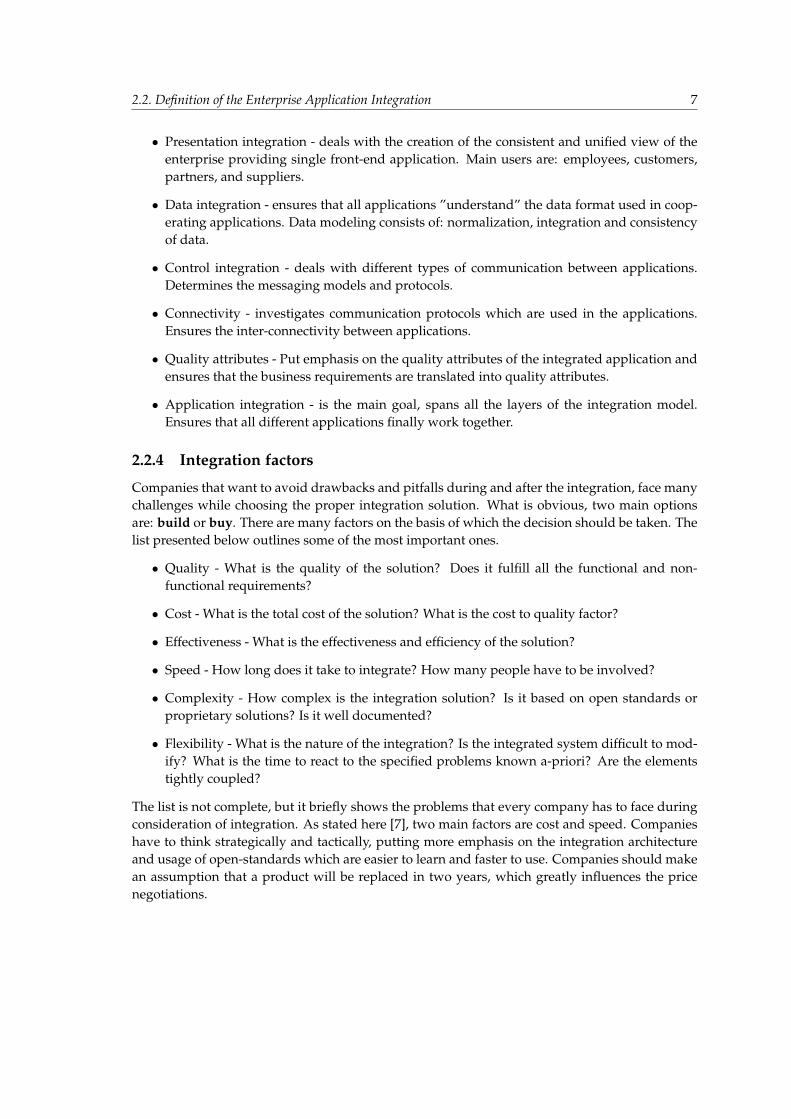
Huge enterprises typically consist of hundreds of applications that are proprietary-built, obtainedfrom a third-party, part of a legacy system, operating in multiple tiers, operating systems, plat-forms and localizations. An enterprise that comprises thirty different web sites, three instancesof SAP and countless departmental solutions is commonly seen. There are many reasons for thefine granularity of contemporary enterprise applications:
• Design complexity - writing business applications poses great difficulties. Creating a sin-gle, monolithic, extendible and easily manageable application to run a complete businessenterprise is almost impossible.
• Software age - it is not very common that all applications used in an enterprise are writ-ten at the same point of time. They are being increasingly added during the growth of anenterprise.
• Technologies - some of the enterprise applications are designed using wide variety of spec-ified, different technologies, as it was the general architectural recommendation at the cur-rent stage.
• Legacy solutions - are present in many enterprises. These are the applications with unavail-able source code, no support, no documentation or which are simply too expensive to beredesigned.
• Local requirements - distributing business functions and business operations across multi-ple applications provides an enterprise with flexibility to select the best fitting option at thespecified situation.
• Control - sometimes it is easier to have all administrative tasks done locally in every singleapplication as it improves local accountability.
• Better performance - fine granularity gives the possibility to tune the underlying hardwarespecially for the needs of the installed pieces of software.
• Bad design - application are written ad-hoc without performing adequate research.
• Unknown scope - current integration goals were unknown at the specified application de-sign stage.
On the one hand, users such as customers or business partners which interact with the front-end application do not generally think about the system boundaries and limitations when theyinter-operate with a business. They simply want to execute business functions and get the ex-pected results regardless of the count and complexity of internal systems that the business con-sists of. The view of an enterprise has to be unified, simple and functional to the customer. Onthe other hand, every single application requires specified amount of autonomy which providesdevelopers with space for innovation, improvisation and improvements. Without these elements,when application resides in rigidly integrated, rigorous environment, it could quickly becomeunprofitable and, in the end, dead. Therefore, there is a strong and urgent need for enterpriseapplication integration patterns which cope with all aforementioned aspects which specify suc-cessful and well-considered integration solutions.

2.2. Definition of the Enterprise Application Integration 6
2.2.2 Challenge
During the previous years some of the traditional ways of performing the Enterprise Integrationhave failed, some have shown that the process has to be investigated and improved further on.The most important aspect of the EAI is the way how it is performed. It should be straightforward,standardized, manageable and cheap. According to [82] there is much work to be done in thisfield: ”Integration of information systems is expensive and time consuming. Between 20% and40% of labor costs can be traced to the storage and reconciliation of data. In addition, 70% ofcode in corporate software systems is dedicated to moving data from system to system.” Oneof the reports [7] claims that: ”A well-designed integration infrastructure will enable businessesto become more adaptive in their business processes, while reducing information latency andbusiness cycle times. New, standards-based integration technology is driving down the cost ofapplication integration by approximately 50%.” All facts and numbers show the importance ofthe properly performed EAI.
2.2.3 Integration taxonomy
Enterprise Integration can be considered and performed on different scopes. Please see Figure 2.1and explanation below which present the crucial technical aspects of enterprise integration [82].
Figure 2.1: Integration scopes1
• Requirements and principles - determine the functional and non-functional requirements ofthe integrated enterprise. Use-case modeling is one of the ways of achieving this step.
• Business integration - determines and integrates business processes which span across mul-tiple applications. Business process re-engineering (BPR) is often performed at this stage.
1Figure downloaded from [82].
2.2. Definition of the Enterprise Application Integration 7
• Presentation integration - deals with the creation of the consistent and unified view of theenterprise providing single front-end application. Main users are: employees, customers,partners, and suppliers.
• Data integration - ensures that all applications ”understand” the data format used in coop-erating applications. Data modeling consists of: normalization, integration and consistencyof data.
• Control integration - deals with different types of communication between applications.Determines the messaging models and protocols.
• Connectivity - investigates communication protocols which are used in the applications.Ensures the inter-connectivity between applications.
• Quality attributes - Put emphasis on the quality attributes of the integrated application andensures that the business requirements are translated into quality attributes.
• Application integration - is the main goal, spans all the layers of the integration model.Ensures that all different applications finally work together.
2.2.4 Integration factors
Companies that want to avoid drawbacks and pitfalls during and after the integration, face manychallenges while choosing the proper integration solution. What is obvious, two main optionsare: build or buy. There are many factors on the basis of which the decision should be taken. Thelist presented below outlines some of the most important ones.
• Quality - What is the quality of the solution? Does it fulfill all the functional and non-functional requirements?
• Cost - What is the total cost of the solution? What is the cost to quality factor?
• Effectiveness - What is the effectiveness and efficiency of the solution?
• Speed - How long does it take to integrate? How many people have to be involved?
• Complexity - How complex is the integration solution? Is it based on open standards orproprietary solutions? Is it well documented?
• Flexibility - What is the nature of the integration? Is the integrated system difficult to mod-ify? What is the time to react to the specified problems known a-priori? Are the elementstightly coupled?
The list is not complete, but it briefly shows the problems that every company has to face duringconsideration of integration. As stated here [7], two main factors are cost and speed. Companieshave to think strategically and tactically, putting more emphasis on the integration architectureand usage of open-standards which are easier to learn and faster to use. Companies should makean assumption that a product will be replaced in two years, which greatly influences the pricenegotiations.
2.3. Enterprise Integration Patterns 8
2.3 Enterprise Integration Patterns
Enterprise Integration Patterns are simply widely known design patterns which tell how andusing which building bricks the integration should be performed. They are the set of reusablerules and solutions to commonly known problems occurring during the integration. A great setof enterprise integration patterns is presented in the book ”Enterprise Integration Patterns” byGregor Hohpe and Bobby Woolf [88]. Right now, the most important integration patterns will bediscussed.
2.3.1 Topologies Fundamentals
Topology defines an arrangement of elements. When discussing the topology of an enterprisesystem we can easily notice two kinds of elements:
• hardware artifacts - physical components of the computer system.
• software artifacts - a set of computer programs and applications.
We can also distinguish two levels of abstractions:
• physical level - describes the way that each hardware artifact physically connects to thenetwork. It also describes the means, the sequence, and the protocol that hardware artifactuses to communicate.
• logical level - describes the arrangement of channels, collaborations, and mechanisms thatdifferent software artifacts residing on hardware artifacts use to interoperate.
The subject-matter of this thesis focuses only on the logical level, discussing the paradigmsand design patterns that different software artifacts implement to make the whole topology inter-operable.
2.3.2 Integration Fundamentals
According to this definition [6] there are two main integration foundations which all other inte-gration patterns derive from. These are:
• Mediation;
• Federation;
Mediation
Mediation pattern or mediator pattern is one of the behavioral design patterns described in thebook by ”Gang of Four” [83]. It is a software design pattern that specifies an unified mediatorelement with a commonly known interface which acts as a intermediary. Elements of the systemdo not interact with each other. They communicate through the mediator which encapsulates themediation logic instead.
2.3. Enterprise Integration Patterns 9
Federation
There are numerous unclear opinions about the popular federation pattern. Some people call it afacade, the others - a federation. There is, however, a clear difference between these two patterns.Facade is a software design pattern that provides a unified interface to a system, for example, toreduce the dependencies or wrap a poorly written APIs with a single well-designed API. A feder-ation pattern is a more abstract integration pattern which defines interoperation between systemsor applications. If a set of systems provides the same functions and can interoperate forming onesystem that provides the the same functions as the constituent systems, then architecture is basedon the federation pattern. Federations are main means which provide systems with scalability.There are two types of federations [8]:
• ”homogeneous federations - composed of like subsystems with at least the same interfacesand usually the same implementations and exposing the same interface for the composedsystem”;
• ”heterogeneous federations - where some amount of mediation is required to coerce somesubsystem”;
The confusing misunderstanding is probably caused by the Data Federation Pattern [9] that ad-dresses the data integration problem. It has a similar approach to a ”facade” pattern in objectprogramming while having the word ”federation” in its name.
2.3.3 Properties of integration solutions
Whenever application integration is considered there are many common architectural elements(later called integration services), regardless of specified integration pattern. Data transformationand connectivity are the aforementioned pieces of critical importance. The list presented below,based on article by Microsoft Press [10], tries to summarize all of these common aspects.
• Messaging (Routing) - Core of the integration system. It supports data reconciliation, trans-formation and routing among integrated applications.
• Adapters and Connectors (Transformation) - Elements which create an abstraction layer forthe transfer and data protocols. It is an extendible framework which supports connectivityto all of the specified applications.
• Supporting Platform - Services to support cooperation of application regardless of hardwareand software platform.
• Management and Administration (Registration) - Services to support deployment of arti-facts, monitoring and runtime management of the integrated system.
• Security - Provides authentication and authorization mechanisms, like single sign-on2.
• Monitoring for B2B Processes - Services whose main goal is to monitor the business trans-actions that are executed in the integrated system. Monitoring consists of status activitymonitoring and failure monitoring.
2http://en.wikipedia.org/wiki/Single sign-on
2.3. Enterprise Integration Patterns 10
• Business Process Management - ”If business-to-business transactions are to be automatedthrough the exchange of messages and documents, it is necessary for an EI platform toprovide a set of support functions for these document exchanges, such as receipts and ac-knowledgments, activity status monitoring, failure or out-of-process alerts, and compen-satory events. This feature set is one of the most important to consider when differentiatingtruly comprehensive EI platforms.” [10]
2.3.4 Point to point Integration
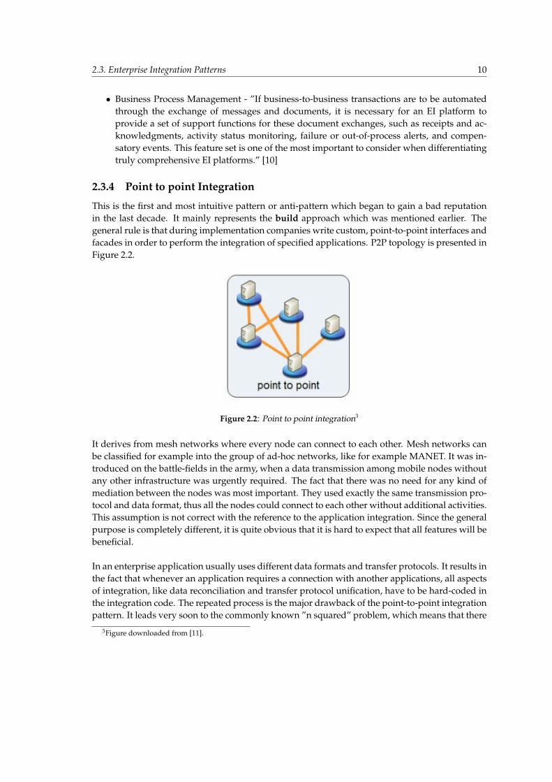
This is the first and most intuitive pattern or anti-pattern which began to gain a bad reputationin the last decade. It mainly represents the build approach which was mentioned earlier. Thegeneral rule is that during implementation companies write custom, point-to-point interfaces andfacades in order to perform the integration of specified applications. P2P topology is presented inFigure 2.2.
Figure 2.2: Point to point integration3
It derives from mesh networks where every node can connect to each other. Mesh networks canbe classified for example into the group of ad-hoc networks, like for example MANET. It was in-troduced on the battle-fields in the army, when a data transmission among mobile nodes withoutany other infrastructure was urgently required. The fact that there was no need for any kind ofmediation between the nodes was most important. They used exactly the same transmission pro-tocol and data format, thus all the nodes could connect to each other without additional activities.This assumption is not correct with the reference to the application integration. Since the generalpurpose is completely different, it is quite obvious that it is hard to expect that all features will bebeneficial.
In an enterprise application usually uses different data formats and transfer protocols. It results inthe fact that whenever an application requires a connection with another applications, all aspectsof integration, like data reconciliation and transfer protocol unification, have to be hard-coded inthe integration code. The repeated process is the major drawback of the point-to-point integrationpattern. It leads very soon to the commonly known ”n squared” problem, which means that there
3Figure downloaded from [11].
2.3. Enterprise Integration Patterns 11
are at most ”n squared” connections among applications. Any kind of addition of new applica-tion results in at most ”n” new connections and interfaces, which actually causes additional costs.This kind of topology, known as ”Big ball of mud” [12], appears to have no distinguishable archi-tecture, it is hard to manage and code reusability is poor. Summarized list of the point-to-pointfeatures is presented below.
Advantages:
• Simplest approach, quickest option for small enterprises;
• Minimizes the data transfer time as the connection is direct;
• Provides redundancy of connection paths (multi-hop connections), in case of direct connec-tion failure;
• Graph theory can be applied to the path management;
Disadvantages:
• Integration anti-pattern;
• Addition of new system results in at most ”n” new connections and integration interfaces;
• Unmanageable in big systems with ”n squared” connections;
• Proprietary integration code is duplicated and it is difficult to maintain, to extend, to test,and to manage;
• Does not scale at all (”Big ball of mud” architecture), good only for small systems;
• Implements neither federation nor mediation pattern. Mediation interfaces are hard codedin every application;
It is very hard to say that the point to point integration pattern is bad, and all the other pat-terns are good. However, when rating the solution according to the criteria introduced in Chapter2.3.3 the result is very poor. Every aforementioned integration service has to be implemented asthe proprietary solution, which is expensive, hard to manage and, in most cases, unreusable. P2Pintegration is successfully applied in small enterprises with not many applications and connec-tions but the integrator has to be aware of the main pros and cons during the integration in orderto choose the best fitting solution.
2.3.5 Broker Integration
Broker integration pattern was invented to fill the gap created by the P2P integration. P2P so-lutions were beneficial for small enterprises where the number of application was minimal andall connections were nonvolatile and commonly known. However, when the companies facedgrowth problems, P2P became inefficient, expensive and unmanageable. Therefore, broker inte-gration pattern was introduced.

2.3. Enterprise Integration Patterns 12
Figure 2.3: Broker integration4
Pattern presented in Figure 2.3 introduces the definition of centralized integration brokerwhich links the applications. The main goal of a broker is to decouple source systems from targetsystems by assuming responsibility for interoperability and coordination of communication. Allintegration services are incorporated into the central broker which acts as a intermediary amongapplications. It is located in the center of the system, between the source and target applications.Usually the whole process of communication goes through the broker. Thanks to the central-ized configuration, there is a reduced number of connections which come to ”n” where ”n” is thenumber of systems. It is a great improvement in comparison to P2P topology with ”n squared”connections. When an application is added to the enterprise system, integration with only one el-ement - central broker has to be performed. During this process the integrator has a wide varietyof integration services residing in the broker, thus there is no need to write the whole integrationcode. However, there are also drawbacks. The broker is a single point of failure, which meansthat when it is down, the whole system is down. The problem can be resolved by clustering thecentral machine on which broker resides, but such scalability is limited to the scalability of thismachine. What is obvious, the advantages of the centralized topology automatically entails dis-advantages which come out of the general rule of this topology.
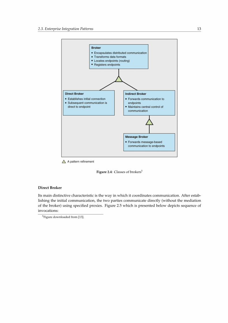
There are three main classes of brokers[13] (Figure 2.4):
• Direct brokers;
• Indirect brokers;
• Message brokers;
4Figure downloaded from [11].
2.3. Enterprise Integration Patterns 13
Figure 2.4: Classes of brokers5
Direct Broker
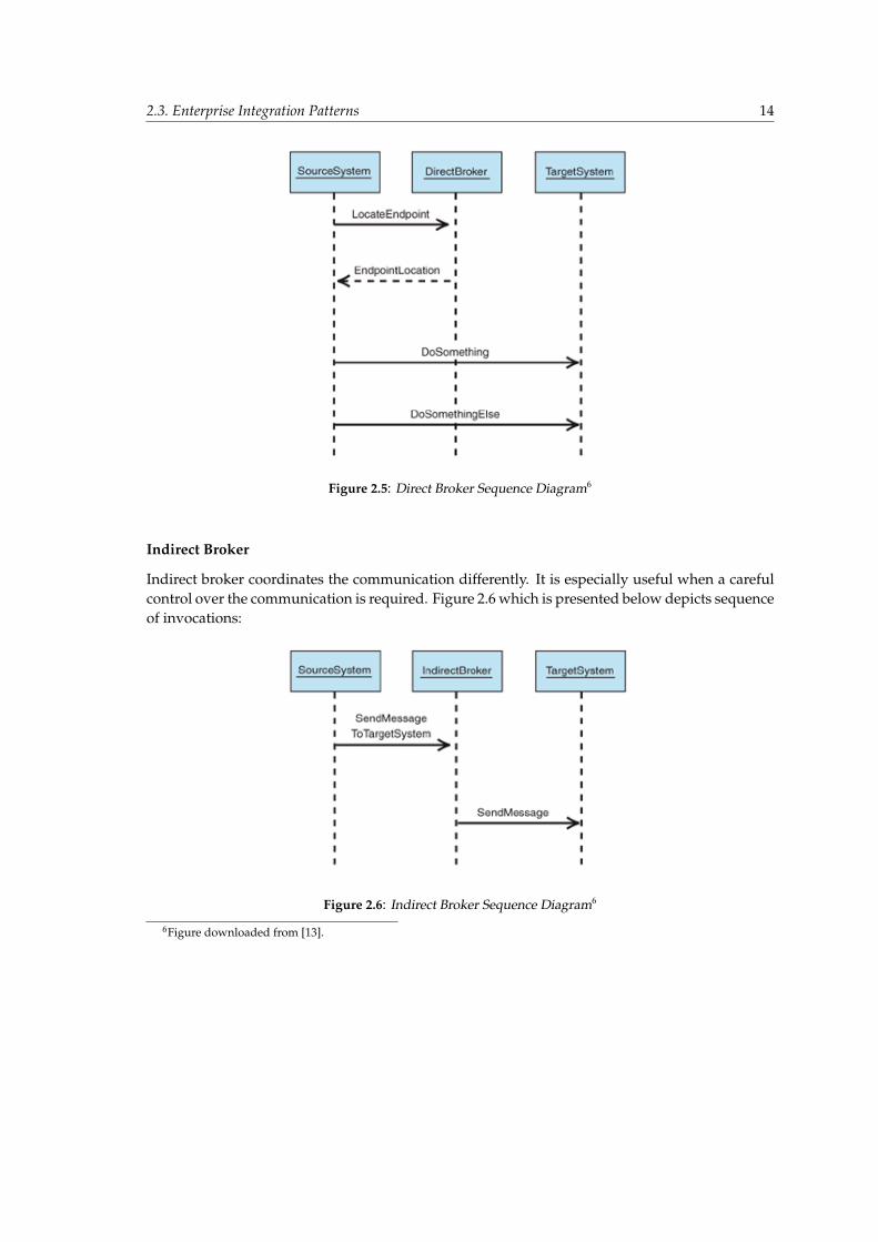
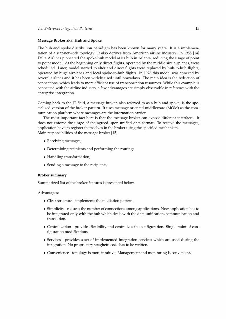
Its main distinctive characteristic is the way in which it coordinates communication. After estab-lishing the initial communication, the two parties communicate directly (without the mediationof the broker) using specified proxies. Figure 2.5 which is presented below depicts sequence ofinvocations:
5Figure downloaded from [13].
2.3. Enterprise Integration Patterns 14
Figure 2.5: Direct Broker Sequence Diagram6
Indirect Broker
Indirect broker coordinates the communication differently. It is especially useful when a carefulcontrol over the communication is required. Figure 2.6 which is presented below depicts sequenceof invocations:
Figure 2.6: Indirect Broker Sequence Diagram6
6Figure downloaded from [13].
2.3. Enterprise Integration Patterns 15
Message Broker aka. Hub and Spoke
The hub and spoke distribution paradigm has been known for many years. It is a implemen-tation of a star-network topology. It also derives from American airline industry. In 1955 [14]Delta Airlines pioneered the spoke-hub model at its hub in Atlanta, reducing the usage of pointto point model. At the beginning only direct flights, operated by the middle size airplanes, werescheduled. Later, model started to alter and direct flights were replaced by hub-to-hub flights,operated by huge airplanes and local spoke-to-hub flights. In 1978 this model was annexed byseveral airlines and it has been widely used until nowadays. The main idea is the reduction ofconnections, which leads to more efficient use of transportation resources. While this example isconnected with the airline industry, a few advantages are simply observable in reference with theenterprise integration.
Coming back to the IT field, a message broker, also referred to as a hub and spoke, is the spe-cialized version of the broker pattern. It uses message oriented middleware (MOM) as the com-munication platform where messages are the information carrier.
The most important fact here is that the message broker can expose different interfaces. Itdoes not enforce the usage of the agreed-upon unified data format. To receive the messages,application have to register themselves in the broker using the specified mechanism.Main responsibilities of the message broker [15]:
• Receiving messages;
• Determining recipients and performing the routing;
• Handling transformation;
• Sending a message to the recipients;
Broker summary
Summarized list of the broker features is presented below.
Advantages:
• Clear structure - implements the mediation pattern.
• Simplicity - reduces the number of connections among applications. New application has tobe integrated only with the hub which deals with the data unification, communication andtranslation.
• Centralization - provides flexibility and centralizes the configuration. Single point of con-figuration modifications.
• Services - provides a set of implemented integration services which are used during theintegration. No proprietary spaghetti code has to be written.
• Convenience - topology is more intuitive. Management and monitoring is convenient.
2.3. Enterprise Integration Patterns 16
Disadvantages:
• Single point of failure - when the broker is down, the enterprise is down.
• Congestion point - performance of the system is mainly dependent on the performance ofthe broker. It can be a bottleneck.
• Complex proprietary solution - brokers are usually heavy, ”all-in-one” proprietary solutionsbased on closed, corporate standards, which makes them very complex to understand anduse. Using such solutions indicates in many cases hiring a third-party, consulting companywhich performs integration and trains developers and stuff how to use the corporate broker.Undoubtedly, it generates high costs.
Broker pattern solved the ”n squared” problem caused by P2P unstructured integration. Pat-tern is successfully implemented and brought into the real business. Main implementations arelicensed, proprietary, vendor-dependent solutions, which are very expensive. The utilization ofthe technology cannot be done ad-hoc as the level of complexity is very high, which also increasesthe integration costs. Work force costs are also worth mentioning as it takes a lot of time to getacquainted with all vendor-specific solutions.
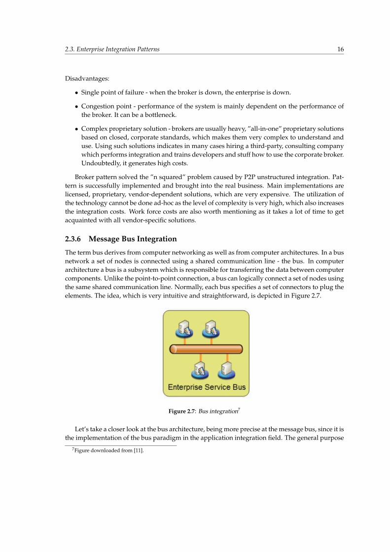
2.3.6 Message Bus Integration
The term bus derives from computer networking as well as from computer architectures. In a busnetwork a set of nodes is connected using a shared communication line - the bus. In computerarchitecture a bus is a subsystem which is responsible for transferring the data between computercomponents. Unlike the point-to-point connection, a bus can logically connect a set of nodes usingthe same shared communication line. Normally, each bus specifies a set of connectors to plug theelements. The idea, which is very intuitive and straightforward, is depicted in Figure 2.7.
Figure 2.7: Bus integration7
Let’s take a closer look at the bus architecture, being more precise at the message bus, since it isthe implementation of the bus paradigm in the application integration field. The general purpose
7Figure downloaded from [11].
2.3. Enterprise Integration Patterns 17
is to enable applications to work together in a decoupled manner, so that the applications canbe plugged in and out without affecting the behavior of others. Message bus behaves as themessage broker between plugged applications. It automatically reduces the number of point-to-point connections as the only connection which an application has to initiate, is the link with thebus. Message Bus is a combination of:
• common description language;
• common command set;
• messaging infrastructure;
which allows different systems to interoperate using a specified set of well-known interfaces.The main idea of the bus integration is based on the agreed-upon common description language(CDL) which could be understood by all parts of the system. It is a layer of abstraction. Wheneveran application has to be plugged into the bus, there are certain steps to follow:
• describe the data in the CDL format;
• describe the services in the CDL format;
When an application wants to use another application, it simply sends messages to the bus usingthe common command set. Prepared messages have to comply with the specified format whichthe bus expects (CDL). Invocation arguments as well as the invocation results are also describedusing the CDL, so the interoperability is provided. Messaging infrastructure provides the appli-cation with the possibility to communicate in a reliable and robust way. Messages are the carriesof information. Usually, the bus does not preserve the message order as this additional logic isnot required.
The main motto of the Message Bus can be described in such a way: logically centralized,physically decentralized [11]. The bus, which is the main building brick of the integrated appli-cation, supports distribution in a federated manner, which means that constituent buses coopera-tively implement the greater system with the same functions as the constituent buses. This is theexact example of the federation pattern described in Section 2.3.2. Distribution and federationare the key aspects provided by the bus.
The messaging mechanism of the bus can be implemented using one of these:
• Message router;
• Publish/subscribe mechanism;
Message Router
The main goal of message router is to consume messages from one channel and republish themto different target channels depending on a set of conditions. What is also important, messagerouter does not change the content of the routed messages.
The taxonomy of message routers is presented from the ”Enterprise Integration Book” [88].
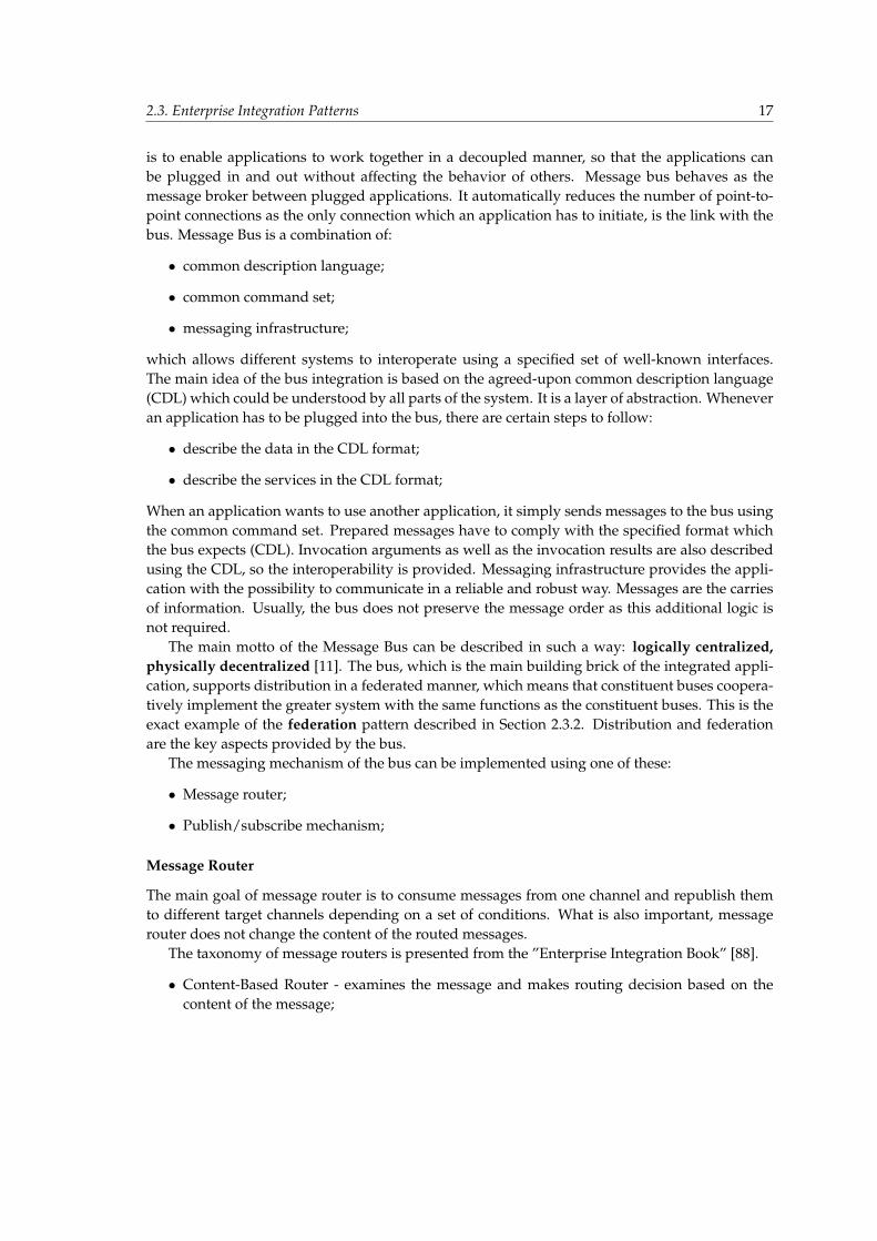
• Content-Based Router - examines the message and makes routing decision based on thecontent of the message;
2.3. Enterprise Integration Patterns 18
• Message Filter - has only one output channel; when message matches specified criteria, it isrouted, when not it is dropped;
• Recipient List - computes recipient list, then sends copy of message to all recipients;
• Splitter - publishes new message for each element of the original message
• Aggregator - gathers and correlates messages, then sends correlated messages as a one mes-sage to the output channel;
• Resequencer - contains an internal buffer; it stores out-of-sequence messages until a com-plete sequence is obtained, then the messages are routed;
• Composed Message Processor - splits the message up, routes the sub-messages to the ap-propriate destinations and re-aggregates the responses back into a single message;
• Scater-Gather - routes a request message to the a number of recipients; collect the responsesand distill them into a single response message;
• Routing Slip - attaches the routing list to the message and sends the message to the firstrecipient from the list; the recipient sends the message to the next recipient from the list; theprocess is repeated until the end of the list is reached;
• Process Manager - uses a process manager to generate processing sequence and to deter-mine next step on the basis of intermediate results;
Publish/Subscribe Mechanism
The main goal of publish/subscribe mechanism is to send a message, whenever it is published,to all subscribed recipients. There are three main types of Publish/Subscribe pattern [16]:
• List-Based Publish/Subscribe - keeps a list of published topics and subscribers and notifieseach one on event;
• Broadcast-Based Publish/Subscribe - does not determine the subscribers; broadcasts themessage to all recipients in the bus;
• Content-Based Publish/Subscribe - matches message against specified criteria and thensends message to interested subscribers;
Summary
Currently, message Bus pattern goes one step further and takes the lead. Not only does it con-tain all advantages of the broker architecture, but it also solves some inconvenient problems. Itsimplifies and standardizes the approach of integration as well as introduces a federated man-ner of solving the broker clustering problem. Message buses are one of the most sophisticatedintegration solutions and are nowadays widely used in business.
2.3. Enterprise Integration Patterns 19
2.3.7 Comparison
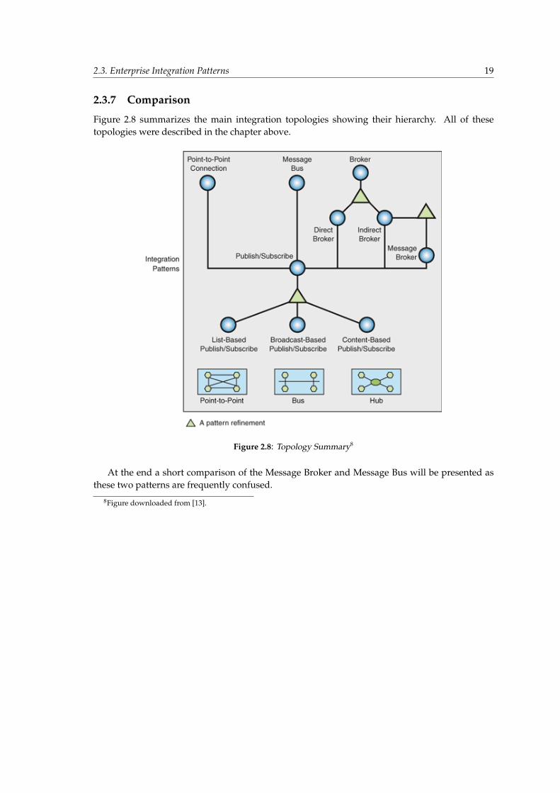
Figure 2.8 summarizes the main integration topologies showing their hierarchy. All of thesetopologies were described in the chapter above.
Figure 2.8: Topology Summary8
At the end a short comparison of the Message Broker and Message Bus will be presented asthese two patterns are frequently confused.
8Figure downloaded from [13].
2.4. Enterprise Service Bus 20
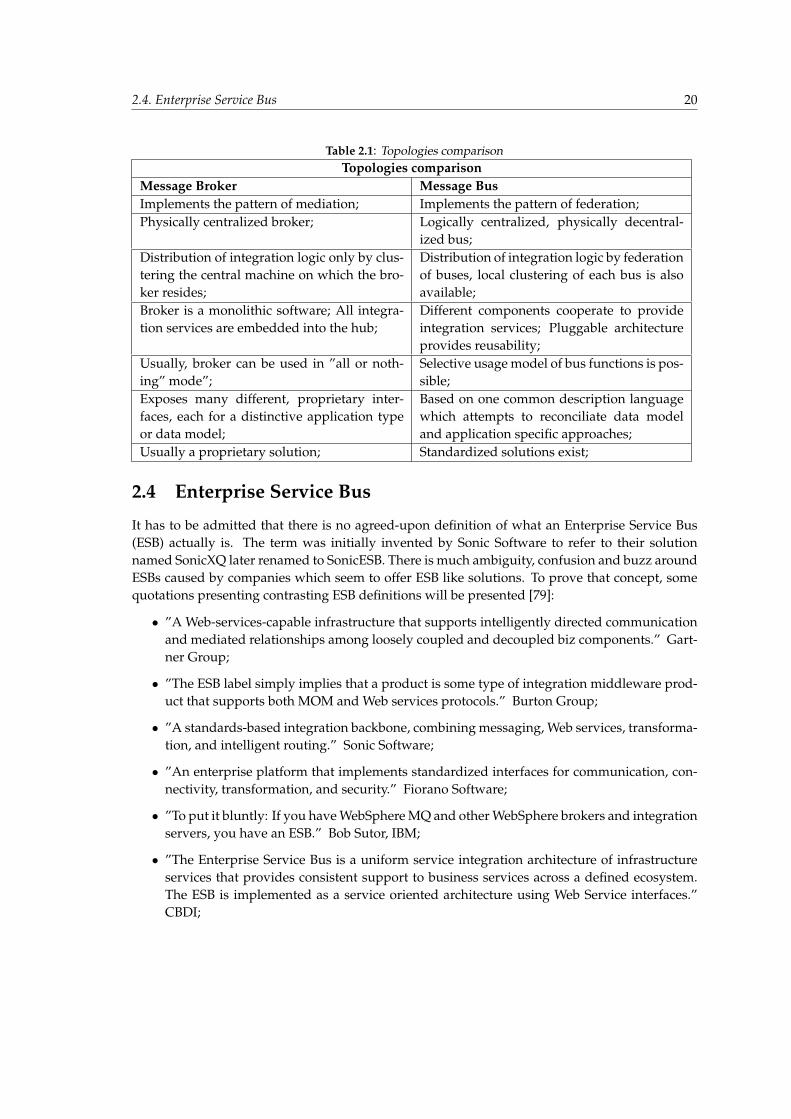
Table 2.1: Topologies comparisonTopologies comparison
Message Broker Message BusImplements the pattern of mediation; Implements the pattern of federation;Physically centralized broker; Logically centralized, physically decentral-
ized bus;Distribution of integration logic only by clus-tering the central machine on which the bro-ker resides;
Distribution of integration logic by federationof buses, local clustering of each bus is alsoavailable;
Broker is a monolithic software; All integra-tion services are embedded into the hub;
Different components cooperate to provideintegration services; Pluggable architectureprovides reusability;
Usually, broker can be used in ”all or noth-ing” mode”;
Selective usage model of bus functions is pos-sible;
Exposes many different, proprietary inter-faces, each for a distinctive application typeor data model;
Based on one common description languagewhich attempts to reconciliate data modeland application specific approaches;
Usually a proprietary solution; Standardized solutions exist;
2.4 Enterprise Service Bus
It has to be admitted that there is no agreed-upon definition of what an Enterprise Service Bus(ESB) actually is. The term was initially invented by Sonic Software to refer to their solutionnamed SonicXQ later renamed to SonicESB. There is much ambiguity, confusion and buzz aroundESBs caused by companies which seem to offer ESB like solutions. To prove that concept, somequotations presenting contrasting ESB definitions will be presented [79]:
• ”A Web-services-capable infrastructure that supports intelligently directed communicationand mediated relationships among loosely coupled and decoupled biz components.” Gart-ner Group;
• ”The ESB label simply implies that a product is some type of integration middleware prod-uct that supports both MOM and Web services protocols.” Burton Group;
• ”A standards-based integration backbone, combining messaging, Web services, transforma-tion, and intelligent routing.” Sonic Software;
• ”An enterprise platform that implements standardized interfaces for communication, con-nectivity, transformation, and security.” Fiorano Software;
• ”To put it bluntly: If you have WebSphere MQ and other WebSphere brokers and integrationservers, you have an ESB.” Bob Sutor, IBM;
• ”The Enterprise Service Bus is a uniform service integration architecture of infrastructureservices that provides consistent support to business services across a defined ecosystem.The ESB is implemented as a service oriented architecture using Web Service interfaces.”CBDI;
2.4. Enterprise Service Bus 21
Smoke screen created by this definitions completely covers the main goal and general purposeof the ESB. Straightforward architectural definition of this pattern will be presented later on, butfirstly the environment in which the ESB resides, will be briefly introduced as these two elementsare tightly connected.
2.4.1 Service Oriented Architecture as ESB environment.
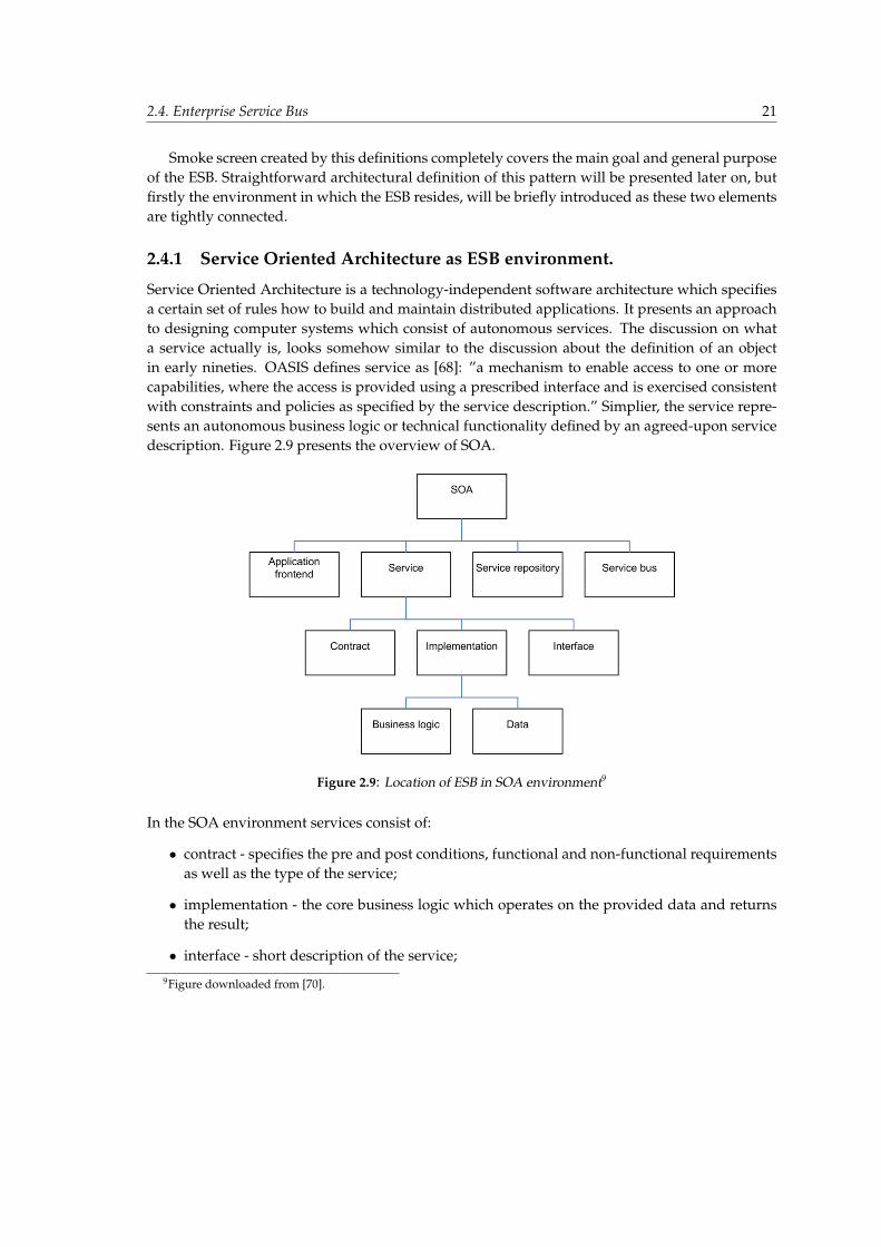
Service Oriented Architecture is a technology-independent software architecture which specifiesa certain set of rules how to build and maintain distributed applications. It presents an approachto designing computer systems which consist of autonomous services. The discussion on whata service actually is, looks somehow similar to the discussion about the definition of an objectin early nineties. OASIS defines service as [68]: ”a mechanism to enable access to one or morecapabilities, where the access is provided using a prescribed interface and is exercised consistentwith constraints and policies as specified by the service description.” Simplier, the service repre-sents an autonomous business logic or technical functionality defined by an agreed-upon servicedescription. Figure 2.9 presents the overview of SOA.
Figure 2.9: Location of ESB in SOA environment9
In the SOA environment services consist of:
• contract - specifies the pre and post conditions, functional and non-functional requirementsas well as the type of the service;
• implementation - the core business logic which operates on the provided data and returnsthe result;
• interface - short description of the service;
9Figure downloaded from [70].
2.4. Enterprise Service Bus 22
The main guiding principles of SOA accroding to [70] are: loose coupling, reuse, granular-ity, modularity, composability, componentization, and interoperability. Not going into details, itmeans that services are reusable and granular building bricks or the low level entities which ap-plication should consist of. Whenever a system is built, a developer chooses required services,designs the business process and composes the applications using, for example, a graphical tool.Great emphasis is put on the reusability as it was a main concern of the software industry. Whatis very important, SOA is technology independent. It is a common mistake to claim that SOAis tightly coupled with the Web Services. SOA architecture can be implemented using a widevariety of technologies, like [70]: SOAP, REST, RPC, DCOM, CORBA, WCF or last but not leastWeb-Services.
Summing up, SOA is a modern, thoroughly different approach to software design from theprevious ones, as earlier computer systems were formed as monolithic, coarse-grained, unreusableentities. The primary goal of SOA is [56] ”to align the business world with the IT world in a waythat makes both more effective”.
2.4.2 ESB Definition
SOA architecture defines the set of rules how to design and implement a distributed application.These rules apply whenever new applications are created, as well as when old or legacy systemsare redesigned. ESB pattern greatly fits into the SOA since it is fully compliant with its paradigms.It encompasses all amenities of SOA as well as provides a set of sophisticated features, describedlater on.
Definition of an ESB presented in this work goes as follows: ESB is a pattern which is the SOA-oriented extension of the bus integration pattern. It is an integration pattern as it fulfills all therequired conditions which are described in Chapter 2.3.6. However, ESB goes beyond as it is SOAoriented. It is not supposed to implement SOA architecture but it was invented to facilitate theengineering and utilization of modern SOA. Alike SOA, ESB is not bound to any specific technol-ogy, it only defines a set of features which a ESB solution should consist of.
Generally, on the highest level of abstraction ESB provides:
• Bus integration pattern;
• SOA runtime environment;
ESB as integration pattern
In the area of SOA, integration can be described as service virtualization [57], what describes thefeature of virtualizing the following factors during the service interactions:
• Protocol and pattern - the participants of interaction need not use the same transfer protocol(TCP, UDP, HTTP, SOA, etc.) or interaction pattern (synchronous/asynchronous, request-response, only-in, etc.). ESB should provide the whole required mediation.
• Interface - requester and responder need not use the same interface of the same service.ESB should provide the ability to separate Business Service (contract 2.4.1) from ServiceImplementation (implementation 2.4.1) and interface;

2.4. Enterprise Service Bus 23
• Identity (transparency of the service location) - the requester of interaction need not knowthe identity (for example address) of the responder to request a service. Service could beprovided by any of providers from different physical locations. The list of providers andtheir identities is known only to the ESB and, what is important, may change without im-pacting the requester side.
ESB as a runtime environment
One of the most important principles of ESB as the runtime environment is the aspect oriented con-nectivity [57] which allows to inject cross-cutting aspects between service invocations in order toadd the support of: security, management, logging, auditing and transaction management. Thisfeature is similar to the Request Interceptor specified in the Enterprise Service Beans standard.ESB should also embed the advantages of an application container and provide the services withthe runtime facilities such as the support of deployment in a high availability configuration. Theenvironment should also support scalability, management and reliability.
ESB capabilities
According to Mark Wright, [108] ESB should be defined by specifying the core facilities whichform the main characteristics of an ESB. They can be grouped under the parent, logical compo-nent which they belong to. However, in this work the definitions as well as the grouping areextended, redefined and brought to the different level of abstraction. The list of ESB logical com-ponents and their functions is presented below.
Rules Engine (can be implemented by the Message Router, described in detail here: 2.3.6)
• Routing;
• Message Transformation;
• Message Enhancement;
• Message Processing;
Service Registry:
• Service Mapping - ability to map service contract into the corresponding service implemen-tation;
Service Mediator:
• Protocol Transformation - ability to expose service using different types of protocols; possi-ble thanks to the usage of CDL;
Business Processor (ability to coordinate complex business processes):
• Service Orchestration - orchestrates service in order to form a business process; services arecoordinated in a centralized way, coordination requires a central point - mediator; processescan be specified using, for example, BPEL;

2.4. Enterprise Service Bus 24
• Service Choreography - coordination realized in a decentralized manner; can be imple-mented using the ”routing slip” function of the message router;
Service Container:
• Security (Authentication and Authorization);
• Transaction Support;
• Context Propagation;
• Management;
• Logging;
• Deployment environment;
Service Manager (Monitoring features will be discussed later on):
• Business Monitoring - ability to track, monitor, analyze and profile logical business opera-tions, executed in the bus;
• System Monitoring - ability to monitor main system characteristics and quality informa-tions;
• Service Level Agreement - business auditing;
Federation of ESBs
Federation (2.3.2) is one of the main concepts which the message bus pattern is based on. How-ever, in reference with Enterprise Service Bus, this paradigm was specified mainly theoretically;some of the implementations do not support it at all. Currently, some trends of change are em-phatically visible since the newest Forrester report [85], dated April 2008, reads as follows: ”Theenterprise service bus (ESB) is not a single entity across the enterprise but a federation of ESBsand other SOA infrastructure that work together to ease and control service usage across theenterprise.” According to this report: ”ESB federation enables multiple ESBs to work together,seamlessly and transparently, to enable enterprisewide access to and management of servicesacross multiple domains, each of which has potentially different requirements for security, visi-bility, mediation, quality-of-service, and management.” This definition, completly compliant withthe federation pattern described earlier, seems to head of the right direction as the main drawbackof the up-to-date ESB solutions is noticed and there are attempts to resolve it.
According to the report, three models of federation are possible:
• Direct federation - ESBs which host services are directly connected;
• Brokered federation - many ESBs, one acts as a mediator and hosts no services; all the otherESBs host services and connect with each other using the mediator;
• Full federation - many ESBs, one acts as a mediator but also can host services; direct orindirect communication possible;
2.4. Enterprise Service Bus 25
2.4.3 ESB implementations
There are many software solutions which are claimed to be ESB compliant, however some of themhave the ESB only in theirs name. The list presented below outlines the main ESB implementa-tions presenting the name of the product as well as the producer.
• Aqua Logic Service Bus, BEA;
• WebSphere ESB, IBM;
• JBoss ESB, JBoss;
• OpenESB, SUN Microsystems;
• ServiceMix, Apache;
• Enterprise ServiceMix (FUSE), Iona;
• SonicESB, Sonic Software;
• ESB, IWay Software;
• WSO2 Enterprise Service Bus, open project;
• ChainBuilder ESB, Bostech;
• Mule, open project;
• PEtALS, OW2;
• BizTalk Server products family, Microsoft;
2.4.4 Summary
ESB is currently one of the most up-to-date solutions in the area of enterprise integration and ser-vice oriented architecture. It is considered to have significant influence on design of distributedsoftware solutions across the world. It proved to be very successful and now it is a top-sellingproduct offered by most of the major IT market players. However, in a meaningful article [56]Bobby Woolf, respectable software architect and co-author of the ”Enterprise Integration Pat-terns” book, questions the legitimacy of an ESB. The author claims that it is not beneficial toadopt an ESB without an attempt to identify, design and implement the autonomous services,which are the underlying, building bricks of every SOA. It is stated that clients want to buildonly ESBs not paying attention to business requirements, as they seek rapid profit growth. Theywant to create an infrastructure and then wait and hope that some SOA will use it. Author putsthe emphasis on the fact that ESB without services does not create a business value as this is auseless infrastructure without customers (services) which benefit from it. The main motto readsas follows: ”Don’t build an ESB by itself; build it as part of a SOA”.
2.5. Java Business Integration 26
2.5 Java Business Integration
In contrast to the ESB, definition of the JBI is clearly specified in JSR 208. Althought the wordESB can be found only once in the whole document, these two terms have a lot in common. Ac-cording to the specification, [2] ”Java Business Integration (JBI) seeks to address EAI problem bycreating a standards-based architecture for integration solutions. This infrastructure allows third-party components to be ”plugged in” to a standard infrastructure, and allows those componentsto interoperate in a predictable, reliable fashion despite being produced by separate vendors. It isanticipated that this ability to interoperate will create a multivendor ”ecosystem” which will giverise to large pool of integration-related technologies that can be sourced by end users. In addition,this ecosystem will foster new innovations in integration technologies since it will permit inno-vators to concentrate on a particular technology or problem area, without having to worry aboutproviding all the other pieces needed to build a complete integration solution. (...) JBI defineswhat is sometimes termed a ”service container” in Enterprise Service Bus (ESB) systems”. To sumup, JBI standardizes the ESB pattern by specifying a concrete, Java-centric model of ESB.
2.5.1 Background
Looking back, JBI is the ”last but not least” integration technology presented in this work. All theprevious definitions were introduced to present the taxonomy of enterprise integration patterns,describe the most popular solutions and preciously outline the background and origin of JBI. Atthe current stage, when it is stated that JBI derives from ESB which derives from bus integration,all underlying concepts should be well-known. JBI fulfills all conditions to be characterized as en-terprise service bus (2.4.2). The list below accurately explains and summarizes all the JBI featureswith the reference to ESB.
• JBI is an integration pattern (2.4.2) as it virtualizes:
– communication protocol;
– communication pattern;
– interface and identity;
• JBI is a runtime environment (2.4.2). It is often called a ”container of containers”:
– container for plug-in components;
– container for service artifacts which resides in plug-in components;
• JBI acts as intermediary. Components do not interact with each other directly, they com-municate by means of mediated message exchange governed by the normalized messagerouter (NMR) instead (2.3.6).
• JBI is SOA-oriented as it embraces a service-oriented approach. It is based on Web Servicesmodel.
• JBI encompasses all the capabilities each ESB should consist of (2.4.2).
• JBI is standardized and based on open standards:
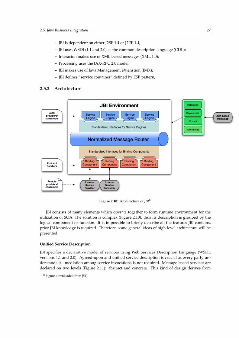
2.5. Java Business Integration 27
– JBI is dependent on either J2SE 1.4 or J2EE 1.4;
– JBI uses WSDL(1.1 and 2.0) as the common description language (CDL);
– Interacion makes use of XML based messages (XML 1.0);
– Processing uses the JAX-RPC 2.0 model;
– JBI makes use of Java Management eXtenstion (JMX);
– JBI defines ”service container” defined by ESB pattern;
2.5.2 Architecture
Figure 2.10: Architecture of JBI10
JBI consists of many elements which operate together to form runtime environment for theutilization of SOA. The solution is complex (Figure 2.10), thus its description is grouped by thelogical component or function. It is impossible to briefly describe all the features JBI contains,prior JBI knowledge is required. Therefore, some general ideas of high-level architecture will bepresented.
Unified Service Description
JBI specifies a declarative model of services using Web Services Description Language (WSDLversions 1.1 and 2.0). Agreed-upon and unified service description is crucial as every party un-derstands it - mediation among service invocations is not required. Message-based services aredeclared on two levels (Figure 2.11): abstract and concrete. This kind of design derives from
10Figure downloaded from [51].
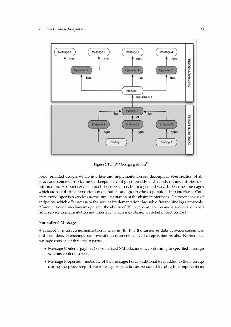
2.5. Java Business Integration 28
Figure 2.11: JBI Messaging Model10
object-oriented design, where interface and implementation are decoupled. Specification of ab-stract and concrete service model keeps the configuration tidy and avoids redundant pieces ofinformation. Abstract service model describes a service in a general way. It describes messageswhich are sent during invocations of operations and groups these operations into interfaces. Con-crete model specifies services as the implementation of the abstract interfaces. A service consist ofendpoints which offer access to the service implementation through different bindings protocols.Aforementioned mechanisms present the ability of JBI to separate the business service (contract)from service implementation and interface, which is explained in detail in Section 2.4.1.
Normalized Message
A concept of message normalization is used in JBI. It is the carrier of data between consumersand providers. It encompasses invocation arguments as well as operation results. Normalizedmessage consists of three main parts:
• Message Content (payload) - normalized XML document, conforming to specified messagescheme; content carrier;
• Message Properties - metadata of the message; holds additional data added to the messageduring the processing of the message; metadata can be added by plug-in components as
2.5. Java Business Integration 29
well as system components;
• Message Attachment - additional part of the content, which is ,for example, non-XML, canbe attached as an attachment; data handler for such content has to be specified;
The main goal of the normalized message is to provide interoperability between components.
Normalized Message Exchange
Message exchange is the logical entity which describes communication between consumer andprovider in JBI. Not only does it serve as the container for normalized messages that take part inthe exchange, but it also represents the JBI-local portion of service invocation. Message exchangeintroduces the communication pattern which specifies steps of communication. There are fourcommunication patterns:
• In-Only - standard one-way messaging pattern; consumer initiates with a message; providerreplies only with status response that indicates that the exchange is over;
• Robust In-Only - reliable one-way messaging pattern; consumer initiates with a message;provider replies with status or fault response which indicates the correctness of the ex-change;
• In-Out - standard two-way messaging pattern; consumer initiates with a message; providerreplies with status or fault response which indicates the correctness of the exchange; con-sumer responds with a status;
• In Optional-Out - standard two-way messaging pattern; provider response is optional;
Normalized Message Router
Delivery of the messages which take part in message exchanges is provided by the normalizedmessage router (NMR) which is the core of JBI. It performs operations with different qualitiesof service depending on multiple factors, like application state or nature of the message. Threequalities of service are supported by the NMR:
• Best effort - no guarantee of message delivery; message can be dropped, delivered once ormore than once;
• At least once - message will be delivered once or more than once;
• Once and only once - message will be delivered exactly once;
Components
JBI introduces two types of components which can realize two different roles: consumer andprovider. Components are installed during the process called ”Component Installation”.
• Binding Component (BC) - BC provides the virtualization of communication protocol andpattern by performing normalization and denormalization from and to the protocol-specific
2.5. Java Business Integration 30
format. It provides the NMR with the possibility to deal only with normalized communica-tion format. Each BC ”understands” one communication protocol and behaves like connec-tor which allow different kinds of communications with the bus. BC can perform operationsplaying two roles (separately or simultaneously) :
– consumer role - it enables the services deployed in the bus to communicate with exter-nal services.
– provider role - it enables external customers to communicate with the services de-ployed in the bus.
• Service Engine (SE) - SE provides business logic services and transformation services in theJBI environment as well as consume such services. SE enables to construct low-grainedcomplex processes by aggregating and orchestrating other services as well as creates sim-pler, fine-grained services, for example data transformation and enhancement. SEs act ascontainers as they form the runtime environment for services. Whenever a new service iscreated it is deployed to specified SE which supports the technology using which the servicewas implemented. SE can serve as service provider, consumer or both.
Component Framework
JBI provides the component framework which enables the components (BCs and SEs) to interactwith the JBI environment. All the interfaces are agreed-upon and specified. There are two typesof interfaces:
• API (application program interface) - exposed by the JBI framework to BCs and SEs; de-fines the contract between JBI environment and pluggable components in order to achievefunctional goals;
• SPI (service provider interface) - interfaces implemented by the components;
Artifacts
JBI components behave as a type of container which new artifacts are deployed to in order to addnew service consumer or provider logic. For example, it is possible to deploy new style sheets toXSLT-transformation service engine to provide it with new transformation logic. The process ofadding such component-specific artifacts is called ”Artifact Deployment”. There are two types ofartifacts:
• Service Unit (SU) - single deployment package, destined for a single component; content ofservice units is not specified as SUs are opaque to JBI; each SU must contain a JBI-defineddescriptor file in which static services (endpoints) produced and consumed by this SU aredefined;
• Service Assembly (SA) - equivalent of consumer application; SU artifacts are grouped undera higher level entity, called service assembly (SA), which is a set of SUs. Each SA containsservice deployment descriptor which specifies to which component each SU is to be de-ployed. SA concept is sometimes called ”composite service description” (CSD);
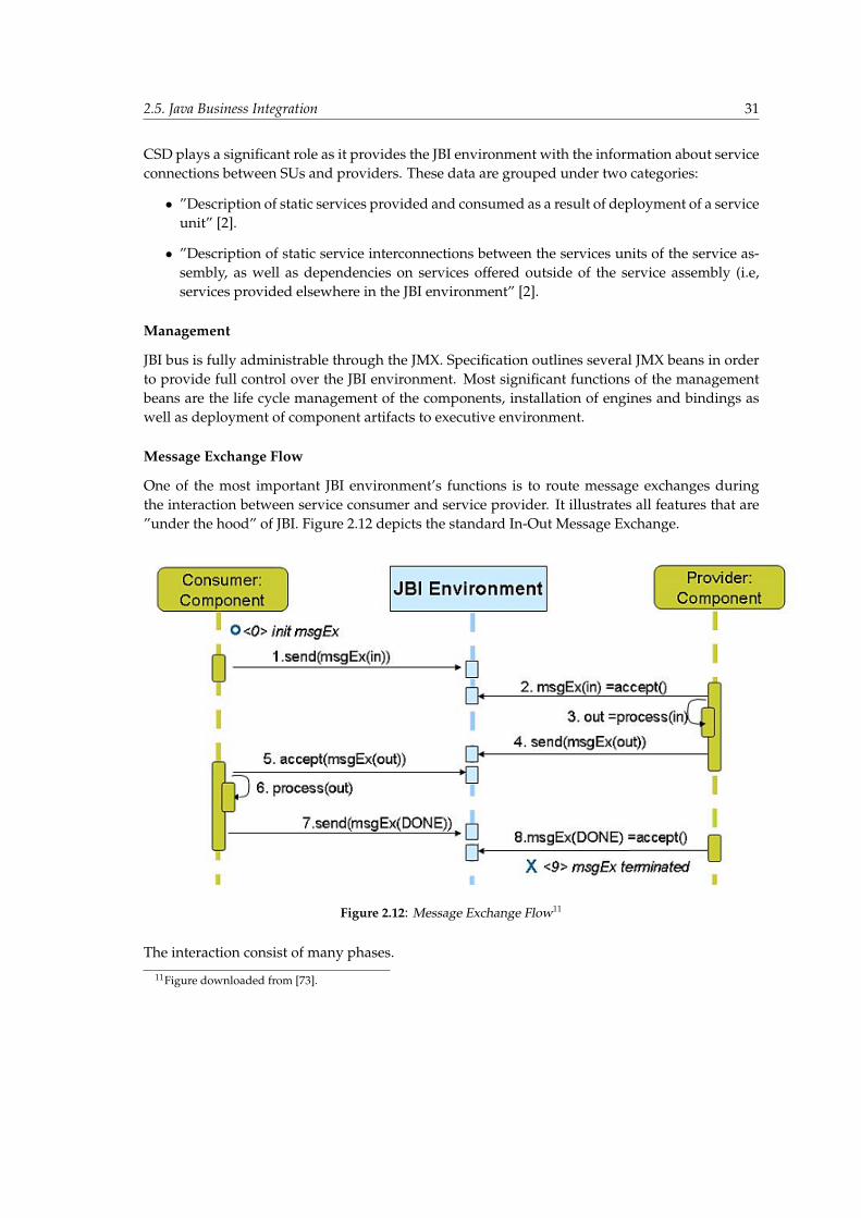
2.5. Java Business Integration 31
CSD plays a significant role as it provides the JBI environment with the information about serviceconnections between SUs and providers. These data are grouped under two categories:
• ”Description of static services provided and consumed as a result of deployment of a serviceunit” [2].
• ”Description of static service interconnections between the services units of the service as-sembly, as well as dependencies on services offered outside of the service assembly (i.e,services provided elsewhere in the JBI environment” [2].
Management
JBI bus is fully administrable through the JMX. Specification outlines several JMX beans in orderto provide full control over the JBI environment. Most significant functions of the managementbeans are the life cycle management of the components, installation of engines and bindings aswell as deployment of component artifacts to executive environment.
Message Exchange Flow
One of the most important JBI environment’s functions is to route message exchanges duringthe interaction between service consumer and service provider. It illustrates all features that are”under the hood” of JBI. Figure 2.12 depicts the standard In-Out Message Exchange.
Figure 2.12: Message Exchange Flow11
The interaction consist of many phases.
11Figure downloaded from [73].
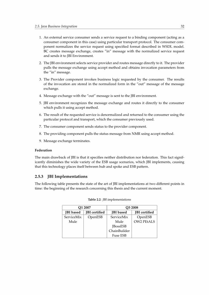
2.5. Java Business Integration 32
1. An external service consumer sends a service request to a binding component (acting as aconsumer component in this case) using particular transport protocol. The consumer com-ponent normalizes the service request using specified format described in WSDL model.BC creates message exchange, creates ”in” message with the normalized service requestand sends it to JBI Environment.
2. The JBI environment selects service provider and routes message directly to it. The providerpulls the message exchange using accept method and obtains invocation parameters fromthe ”in” message.
3. The Provider component invokes business logic requested by the consumer. The resultsof the invocation are stored in the normalized form in the ”out” message of the messageexchange.
4. Message exchange with the ”out” message is sent to the JBI environment.
5. JBI environment recognizes the message exchange and routes it directly to the consumerwhich pulls it using accept method.
6. The result of the requested service is denormalized and returned to the consumer using theparticular protocol and transport, which the consumer previously used.
7. The consumer component sends status to the provider component.
8. The providing component pulls the status message from NMR using accept method.
9. Message exchange terminates.
Federation
The main drawback of JBI is that it specifies neither distribution nor federation. This fact signif-icantly diminishes the wide variety of the ESB usage scenarios, which JBI implements, causingthat this technology places itself between hub and spoke and ESB pattern.
2.5.3 JBI Implementations
The following table presents the state of the art of JBI implementations at two different points intime: the beginning of the research concerning this thesis and the current moment.
Table 2.2: JBI implementations
Q1 2007 Q3 2008JBI based JBI certified JBI based JBI certified
ServiceMix OpenESB ServiceMix OpenESBMule Mule OW2 PEtALS
JBossESBChainBuilder
Fuse ESB

2.6. Conclusion 33
At the beginning, it was decided that OpenESB and SericeMix would be evaluated as thesewere the only two solutions that were worth mentioning with reference to JBI compliance. Ope-nESB was certified to be fully JBI compliant, while ServiceMix was considered to be ”almost”JBI compliant. ServiceMix developers claimed that only some slight incompatibilities exist. Inthe first quarter of 2008, it turned out that PEtALS is also an absorbing solution which is prob-ably ahead of ServiceMix. However, it was too late to include it in the subject of the performedresearch.
2.5.4 Summary
The future of JBI is currently unknown. The approach to standardizing enterprise service busesseems to head off the right direction. The first version of the specification was approved by mostof the major ESB vendors, which set great stores on the tight standardization of ESB. However,later on the general assumptions of the JSR group were partially fulfilled as not many steps weretaken by major ESB vendors to unify existing implementations in compliance with JBI. Only twoJBI certified solutions were designed from scratch after the publication of the JSR, which indicatesthat there were not many movements in the ESB community. It is also very hard to evaluate themarket share of these solutions which does not seem to be meaningful. The uncertain future of JBIis confirmed by the revision summary of the second version of specification which was rejectedby the two main ESB providers that remain unconvinced of the value of JBI solution for SOA. Atthe current moment, it is hard to predict the significance of JBI. According to many resources, thefuture of ESB is beyond any doubt, only time can clarify the role played by JBI.
2.6 Conclusion
The presented chapter outlined a thorough examination of the Enterprise Application Integration. The-oretical research was very important at this stage of work as it broadened the view of the core conceptswhich are discussed across this paper. Precise definition introduced in this chapter helped to demystify thereal differences between integration patterns and laid a grate foundation of clear and accurate theoreticalbackground.
It occurred that point-to-point integration is the most intuitive solution. However, its applicability isvery limited. It is beneficial only for small systems consisting of restricted number of elements. If thatborder is outrun, problems rapidly accumulate. Broker integration seemed to eliminate main problems metin the previous pattern. It is scalable and expansible. The main problem concerning broker integration isthat its implementations are usually proprietary and based on closed standards. It results in an expensiveand unmanageable solution which is hard to maintain. Broker is also a single point of failure, which isunacceptable in some cases. Bus integration pattern is supposed to solve all problems which are mentionedabove. Logically centralized, physically decentralized integration topology which is based on commonlyknown standards and technologies. Shortcomings are almost imperceptible. ESB tends to develop thistrend helping to facilitate the utilization of SOA.
At the end Java Business Integration (JBI) is introduced. It is defined as a standardized, java-orientedimplementation of ESB. All its architectural characteristics are described in order to provide a close exami-nation of the specification. Most of this information is required by following chapters whose main goal is toinvestigate JBI in order to propose its generic monitoring architecture. Chapter is finished with discussion

2.6. Conclusion 34
concerning the future of JBI. It is very hard to predict, whether the specification will be successful sincemany signs precede the gradual deterioration of its significance.
All of the facts mentioned earlier formed a complete description of the target technologies. They havealso deepened the knowledge in the specific domain of the thesis.
Chapter 3
JBI Monitoring
It is not enough to have great qualities; We should also have the management of them. Francois de laRochefoucauld, a French classical author, leading exponent of the Maxime.
3.1 Preamble
The previous chapter introduced the main concepts: Enterprise Application Integration, Enterprise ServiceBus and Java Business Integration, which are the subject of the monitoring system presented in this thesis.This deep analysis of ESB and JBI essentials gives an appropriate background for discussing the aspect ofmonitoring enterprise applications, which is the content of this chapter.
The content is structured in a top-down manner. At the beginning, an enterprise monitoring abstrac-tion is provided which is extended in the following sections relating to JBI specification and some alreadydefined monitoring theories. Finally, the incremental approach is summarized by identification of JBI mon-itoring as a non-trivial challenge.
The monitoring characteristics introduced in the monitoring abstraction are referred to throughout therest of the chapter and allow to evaluate the monitoring capabilities defined in JBI as well as those providedby OpenESB and ServiceMix implementations. The evaluation is performed in JBI status quo section,which additionally discusses the important feature of clustering. It is discussed in the context of ESBfederation introduced in the previous chapter. Clustering support increases difficulty of JBI monitoringsystems and implies the need of a theoretical background provided by Application Response Measurementand Business Application Monitoring. The last section discusses the influence of all aspects mentioned inthis chapter and tries to grasp the architecture implications.
It has to be stressed that the entire content of this chapter is intentionally kept at an abstraction level,which does not refer directly to GlassBus solution that has been introduced later. Focusing on enterprisemonitoring aspects without solution, the context gives a better justification for decisions made in furtherchapters.
3.2 Monitoring abstraction
This section tries to identify some general well-known monitoring abstraction and, having failed to do so,it proposes a simple substitute in the form of a monitoring system classification.
According to a research performed for the purpose of this thesis, a general monitoring theoryapplying to Enterprise Service Bus environment does not exist. There are specifications aimingto standardize application server monitoring, e.g. JSR-77: J2EE Management [17], but such anapproach does not comply with ESB. A theoretical background would allow for a later contextual
3.2. Monitoring abstraction 36
definition of our solution’s capabilities. The shortcomings and advantages of the system wouldbe clearly visible in the context of a more general monitoring abstraction.
The lack of a monitoring abstraction was the motivation of the subject analysis, which resultedin putting forward a monitoring system classification. Monitoring systems can be classified onthe basis of their various characteristics. After evaluation of the key characteristics related tomonitoring, the following system division has been created:
1. Mechanism of information acquiring — How does a system measure the resources that arethe subject of monitoring?
• log analysis — the information regarding the resources is extracted from the logs pro-duced by the resources. It requires constant log parsing and identifying the data thatis important from the monitoring point of view.
• code instrumentation — the resources are equipped with new functionalities that allowto intercept monitoring events as soon as they appear and on this basis to update themonitoring parameters.
2. Model of monitoring parameters evaluation — What patterns are used for the querying ofresources?
• constant pulling — the resources are constantly being queried. When the responsechanges, the monitoring engine updates the parameters. The information is pulledfrom the resources to the system.
• event-driven tracing — the resources trigger events at the status change that are receivedby the system and processed to some monitoring parameters update. The informationis pushed by the resources to the system.
3. Mechanism of information exposition — How can the external system access the system’smonitoring parameters?
• log file — change of the monitoring parameters or periodical status is reported to a logfile.
• well-defined interface — each monitoring parameter is exposed through an interfacewhich defines syntactical and semantic details.
4. Model of monitoring parameters exposition — What patterns are used for the exchange ofthe data with external systems?
• request-response interface — data exchange is realized with a plain old request-responsein a synchronous way (information is pulled by an external actor). Method signatures(or some generic data format) is known a priori.
• notification oriented interface — the data is pushed to an external actor by means of noti-fications. Generic data format is known a prori.
5. Monitoring subject — When analyzing a computer machine (regardless of whether it is onecomputer or a whole cluster), the monitoring parameters can obviously be divided to systemspecific and application specific. A list of sample parameters specific to each monitoring typecan easily be provided:
3.3. JBI monitoring status quo 37
• application — free RAM memory, free hard disk space, CPU usage, number of systemprocesses, number of running applications, each application RAM and CPU usage,network bandwidth usage [107];
• system — number of related network connections, response time from the user’s pointof view, persistence level errors, business level errors, modules usage statistics, busi-ness operation performance;
Depending on the particular monitoring system’s scope and subject, the division into appli-cation and system can be related to different aspects.
6. Time context — How is the available monitoring information related to the present state?
• historical information — there is a record of monitoring parameters history. Queriesabout both the past and present status can be made.
• current information — only the present status is maintained. Past information is over-written with newer information.
7. Monitoring update delay — How far from the present time is the newest available moni-toring state positioned?
• monitoring of real-time — there is no delay between the event and monitoring parameterupdate.
• monitoring of relative near past — there is significant delay between the event and update.
The proposed classification takes the meaningful characteristics of a monitoring system intoaccount, but does not perform any detailed analysis. Its purpose is to provide some referencepoint to a wide range of specifications, technologies, patterns and implementations that are withinthe scope of this thesis.
3.3 JBI monitoring status quo
In order to propose a solution for a monitoring JBI container, a state-of-the-art analysis has to be performed.As it has been defined in the introduction (1), the objective of the thesis is to propose a system comply-ing with JSR-208 and successfully operating on the open source JBI implementations: ServiceMix andOpenESB. This section goes through JBI, ServiceMix and OpenESB analysis and it extracts informationrelevant to monitoring, ipso facto creating the environment for establishing the JBI monitoring solution.
3.3.1 Monitoring from JSR
Java Business Integration introduces basic management and monitoring mechanisms based onthe Java Management Extensions (JMX) technology. Thanks to the design of the JMX architecture,API, patterns and appropriate services supporting both networks and applications, it allows tocontrol and query various resources: network elements, system compounds, application objects,enterprise components. JMX architecture’s flexibility is achieved by a division into the followinglayers:
• Instrumentation level;
3.3. JBI monitoring status quo 38
• Agent level;
• Distributed services level;
The resources managed with JMX are instrumented with Managed Beans (MBeans) and are theprimary architecture entities residing on the instrumentation level. Further JMX details are notdescribed in this thesis — authors assume that JSR-003 and JSR-160 [18, 19] are known to thereader. JBI specification uses MBeans from the instrumentation level to define the managementskeleton interface, which provides the following functionalities:
• Installation of engines and bindings (components);
• Life cycle management of components (start/stop controls);
• Deployment of component artifacts to engines and bindings;
• Monitoring and control;
Unfortunately, most of the methods of JBI’s MBean interfaces are used for management andthere are only a few that can provide functionality of monitoring. The following methods havebeen identified as valuable for monitoring (description of the methods has been omitted due totheir self-explanatory names):
• AdminServiceMBean.getBindingComponents();
• AdminServiceMBean.getEngineComponents();
• DeploymentServiceMBean.getDeployedServiceUnitList(componentName);
• DeploymentServiceMBean.getDeployedServiceAssemblies();
• DeploymentServiceMBean.getServiceAssemblyDescriptor(saName);
• DeploymentServiceMBean.getDeployedServiceAssembliesForComponent(component);
• LifeCycleMBean.getCurrentState();
• InstallerMBean.isInstalled();
These methods can provide the basic information about the structure of the bus: what BC, SE,SU and SA are installed/deployed and which of them are currently running. Such informationis valuable, however there are other important statistics that have to be exposed in a completemonitoring solution. The conclusion is that JSR-208 does not define a sufficient monitoring in-frastructure. The specification basis has to be enriched in order to comply with the assumptionsfrom the theoretical discourse included in the previous chapter (3.5.2).

3.3. JBI monitoring status quo 39
3.3.2 ServiceMix monitoring
The monitoring capabilities of ServiceMix exposed by JMX do not really go beyond those definedin JBI. In ServiceMix versions used for the purpose of this thesis, i.e. 3.1.2 and 3.2.1, only thefollowing monitoring parameters were available 1:
• getInboundExchangeCount;
• getInboundExchangeRate;
• getOutboundExchangeCount;
• getOutboundExchangeRate;
These parameters can be obtained in the context of a particular endpoint or component givingthe information about MessageExchanges counts and rates. ServiceMix extension to JSR MBeansdoes not introduce any significant functionalities. However, the Bus is equipped with other inter-esting mechanisms meaningful for monitoring.
CorrelationId
The first of ServiceMix’s monitoring mechanisms is CorrelationId. In order to avoid confusion ithas to be stressed that it is used in two meanings: as the name of the mechanism which processes -correlates - MessageExchanges that flow through the Bus and as the name of MessageExchange’sproperty, which preserves the actual id of a particular correlation.
Each JBI MessageExchange is uniquely identified through its own id. ME can appear in thebus as a reaction to some external event (e.g. invocation of some web service exposed by a httpbinding component) or as a reaction to processing some other MessageExchange (internal event).MessageExchanges created while processing internal events can be correlated with a parent Mes-sageExchange. The process of correlation can be performed recursively up to the point whenMessageExchange has been created for an external event response. It allows to correlate eachMessageExchange with a root MessageExchange triggered by an external event. ServiceMix’sCorrelationId mechanism uses the above-mentioned correlation process and marks each Message-Exchange with a property of CorrelationId. The value of CorrelationId property is the id of therelated root MessageExchange.
The mechanism of correlating MessageExchange into what is known as the JBI transaction ispresented in great detail in Section 4.3. Please refer to it for a complete understanding.
Event interception
ServiceMix introduces a very flexible mechanism for intercepting various events occurring in thebus. The mechanism relies on a definition of event listeners provided in the packageorg.apache.servicemix.jbi.event. The implementation of each listener is notified about specificevents. The following listeners interfaces are available: 2:
1Information about parameters available in earlier versions of ServiceMix is available here:http://servicemix.apache.org/management.html
2http://servicemix.apache.org/maven/servicemix-core/apidocs/org/apache/servicemix/jbi/event/package-summary.html
3.3. JBI monitoring status quo 40
• ComponentListener — notifies about component installation, deinstallation, starting, stop-ping, shutting down.
• DeploymentListener — notifies about file modifications (ServiceMix specific).
• EndpointListener — notifies about endpoint registration and unregistration.
• ExchangeListener — notifies about sent and accepted MessageExchanges.
• ServiceAssemblyListener — notifies about ServiceAssembly deployment, undeployment,starting, stopping, shutting down.
• ServiceUnitListener — notifies about ServiceUnit deployment, undeployment, starting,stopping, shutting down.
In order to be able to use the described mechanism, an implementation of one of the aboveinterfaces has to be provided and registered in ServiceMix using the following method: JbiCon-tainer.addListener(EventListener listener).
Unfortunately, such an event interception is not compliant with JBI specification. Additionally,there is no similar mechanism in OpenESB — listeners are specific to ServiceMix.
There are few useful components which use the mechanism of event listeners. They are pre-sented in the following paragraphs.
Component and Endpoint visualization ServiceMix has a built-in functionality of bus topol-ogy visualization. Notifications of ComponentListener, DeploymentListener and EndpointLis-tener allow to track changes in the topology. Thanks to that, maintaining of the installed, startedcomponents and the endpoints deployed to them is possible. The knowledge about topologyis a good basis for further analysis of MessageExchange flows occurring between the endpointsin the topology. The topology is provided in a file with the components and endpoints graphdescribed in the DOT language [20]. DOT is a simple plain-text description language which isunderstandable to both humans and computers. DOT files created by ServiceMix have to befurther visualized by one of the many tools capable of DOT handling 3. This step is performedoutside of ServiceMix by the users themselves.
MessageExchange flow visualization Another ServiceMix’s visualization tool which is comple-mentary with the topology provides information about MessageExchange flows. Implementationof ExchangeListener is used, which allows to intercept events of sending and accepting Message-Exchanges in DeliveryChannels of all components running in the bus. MessageExchange inter-ception is enhanced with CorrelationId feature allowing for creating trees of message exchangeflows. As in the case of the topology description, the flow is also provided in DOT language filesand the final step of visualization is the user’s responsibility. Tracing the paths of MessageEx-changes is a meaningful capability that may be used for debugging business logic deployed tothe bus.
3Graphviz - http://www.graphviz.org/ ; AT&T Grappa - http://www.research.att.com/ john/Grappa/ ; C++ BGLhttp://www.boost.org/doc/libs/1 35 0/libs/graph/doc/index.html
3.3. JBI monitoring status quo 41
ServiceMix Audit Audit is one of the ServiceMix’s modules. It focuses on MessageExchanges,which to some extent is analogical to the flow visualization. However, Audit is not concernedwith correlation, maintaining instead a historical record of MessageExchanges. Recorded Mes-sageExchanges are also intercepted in ExchangeListener (see: flow visualization). The moduleprovides an abstraction of the persistence layer allowing for flexible change of the persistencerealization. At the moment, two realizations are available:
• FileAuditor — storing exchanges in regular files;
• JdbcAuditor — storing exchanges in any JDBC compatible resources. For the purpose ofperformance only one table with a message id and serialized content is used;
The persistence layer is additionally enhanced with a full-text search engine - Lucene 4. It appro-priately indexes recorded message exchanges allowing for further content-based search. Just asin the case of the flow visualization, it can be used for debugging, but also as a means of statisticsand some business oriented analysis (cf. Business Intelligence 3.4.2).
Spagic Spagic describes itself as a SOA Enterprise Integration Platform. On the homepage,the following description is provided: ”Spagic is a solution composed by a set of visual toolsand back-end applications oriented towards design, realisation, deploy and monitoring of ESBinfrastructures adherent to the SOA paradigm.” The solution’s monitoring aspect is interestingfor the purpose of this thesis, but the remaining details are out of its scope [21]. Spagic monitoringrefers to an abstraction of a higher level process (analogical to business process) which is realizedby means of ESB, BPM and also JBI. Spagic uses ServiceMix for the purpose of Java BusinessIntegration. The higher level process part, realised by JBI (ServiceMix), can be actively monitored.It comes to following the business transaction through its endpoints and reporting success orpossible failures. Monitoring uses two ServiceMix’s mechanisms:
• ExchangeListener — used to intercept MessageExchanges;
• CorrelationID — for business transaction constructing;
Spagic’s broad functionalities and its monitoring aspect prove the usefulness of the monitoringmechanisms of ServiceMix.
3.3.3 OpenESB monitoring
OpenESB monitoring realization approach differs from the ServiceMix approach. OpenESB lacksvaluable mechanism introduced by ServiceMix: CorrelationId and Event Listeners, but it pro-vides a well-designed Sierra framework dedicated to runtime monitoring. The framework isdescribed on OpenESB Wiki pages [22], which, along with our experience and the results of ex-periments, provides the main reference for this section.
Sierra monitoring focuses mainly on performance characteristics which span across system andapplication monitoring types defined in Section 3.2. This means that every JBI role will benefit fromthe monitoring parameters provided by Sierra (cf. 3.2). The performance evaluation is appliedvery systematically. Firstly, the framework finds the primary JBI entities, in which the context
4Apache Lucene - http://lucene.apache.org/java/docs/
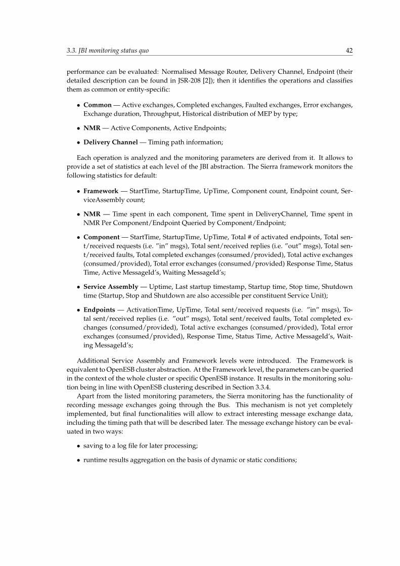
3.3. JBI monitoring status quo 42
performance can be evaluated: Normalised Message Router, Delivery Channel, Endpoint (theirdetailed description can be found in JSR-208 [2]); then it identifies the operations and classifiesthem as common or entity-specific:
• Common — Active exchanges, Completed exchanges, Faulted exchanges, Error exchanges,Exchange duration, Throughput, Historical distribution of MEP by type;
• NMR — Active Components, Active Endpoints;
• Delivery Channel — Timing path information;
Each operation is analyzed and the monitoring parameters are derived from it. It allows toprovide a set of statistics at each level of the JBI abstraction. The Sierra framework monitors thefollowing statistics for default:
• Framework — StartTime, StartupTime, UpTime, Component count, Endpoint count, Ser-viceAssembly count;
• NMR — Time spent in each component, Time spent in DeliveryChannel, Time spent inNMR Per Component/Endpoint Queried by Component/Endpoint;
• Component — StartTime, StartupTime, UpTime, Total # of activated endpoints, Total sen-t/received requests (i.e. ”in” msgs), Total sent/received replies (i.e. ”out” msgs), Total sen-t/received faults, Total completed exchanges (consumed/provided), Total active exchanges(consumed/provided), Total error exchanges (consumed/provided) Response Time, StatusTime, Active MessageId’s, Waiting MessageId’s;
• Service Assembly — Uptime, Last startup timestamp, Startup time, Stop time, Shutdowntime (Startup, Stop and Shutdown are also accessible per constituent Service Unit);
• Endpoints — ActivationTime, UpTime, Total sent/received requests (i.e. ”in” msgs), To-tal sent/received replies (i.e. ”out” msgs), Total sent/received faults, Total completed ex-changes (consumed/provided), Total active exchanges (consumed/provided), Total errorexchanges (consumed/provided), Response Time, Status Time, Active MessageId’s, Wait-ing MessageId’s;
Additional Service Assembly and Framework levels were introduced. The Framework isequivalent to OpenESB cluster abstraction. At the Framework level, the parameters can be queriedin the context of the whole cluster or specific OpenESB instance. It results in the monitoring solu-tion being in line with OpenESB clustering described in Section 3.3.4.
Apart from the listed monitoring parameters, the Sierra monitoring has the functionality ofrecording message exchanges going through the Bus. This mechanism is not yet completelyimplemented, but final functionalities will allow to extract interesting message exchange data,including the timing path that will be described later. The message exchange history can be eval-uated in two ways:
• saving to a log file for later processing;
• runtime results aggregation on the basis of dynamic or static conditions;
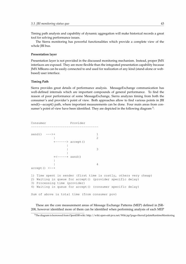
3.3. JBI monitoring status quo 43
Timing path analysis and capability of dynamic aggregation will make historical records a greattool for solving performance issues.
The Sierra monitoring has powerful functionalities which provide a complete view of thewhole JBI bus.
Presentation layer
Presentation layer is not provided in the discussed monitoring mechanism. Instead, proper JMXinterfaces are exposed. They are more flexible than the integrated presentation capability becauseJMX MBeans can be easily connected to and used for realization of any kind (stand-alone or web-based) user interface.
Timing Path
Sierra provides great details of performance analysis. MessageExchange communication haswell-defined internals which are important compounds of general performance. To find thereason of poor performance of some MessageExchange, Sierra analyzes timing from both theconsumer’s and provider’s point of view. Both approaches allow to find various points in JBIsend()—accept() path, where important measurements can be done. Four main areas from con-sumer’s point of view have been identified. They are depicted in the following diagram 5:
Consumer Provider------------------------------------
send() --->+ 1| 2+------> accept()
|| 3|
+<-----+ send()|| 4
accept() <--+
1) Time spent in sender (first time is costly, others very cheap)2) Waiting in queue for accept() (provider specific delay)3) Processing time (provider)4) Waiting in queue for accept() (consumer specific delay)
Sum of above is total time (from consumer pov)
These are the core measurement areas of Message Exchange Patterns (MEP) defined in JSR-208, however identified more of them can be identified when performing analysis of each MEP
5The diagram is borrowed from OpenESB wiki: http://wiki.open-esb.java.net/Wiki.jsp?page=SierraUpdateRuntimeMonitoring
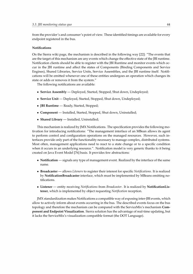
3.3. JBI monitoring status quo 44
from the provider’s and consumer’s point of view. These identified timings are available for everyendpoint registered in the bus.
Notifications
On the Sierra wiki page, the mechanism is described in the following way [22]: ”The events thatare the target of this mechanism are any events which change the effective state of the JBI runtime.Notification clients should be able to register with the JBI Runtime and monitor events which oc-cur in the JBI runtime and affect the states of Components (Binding Components and ServiceEngines), Shared Libraries, Service Units, Service Assemblies, and the JBI runtime itself. Notifi-cations will be emitted whenever one of these entities undergoes an operation which changes itsstate or adds or removes it from the system.”
The following notifications are available:
• Service Assembly — Deployed, Started, Stopped, Shut down, Undeployed;
• Service Unit — Deployed, Started, Stopped, Shut down, Undeployed;
• JBI Runtime — Ready, Started, Stopped;
• Component — Installed, Started, Stopped, Shut down, Uninstalled;
• Shared Library — Installed, Uninstalled;
This mechanism is realized by JMX Notifications. The specification provides the following mo-tivation for introducing notifications: ”The management interface of an MBean allows its agentto perform control and configuration operations on the managed resources. However, such in-terfaces provide only part of the functionality necessary to manage complex, distributed systems.Most often, management applications need to react to a state change or to a specific conditionwhen it occurs in an underlying resource.”. Notification model is very generic thanks to it beingcreated on Java Event Model [76] basis. It provides few abstractions:
• Notification — signals any type of management event. Realized by the interface of the samename.
• Broadcaster — allows Liteners to register their interest for specific Notifications. It is realizedby NotificationBroadcaster interface, which must be implemented by MBeans emitting no-tifications.
• Listener — entity receiving Notifications from Broadcaster. It is realized by NotificationLis-tener, which is implemented by object requesting Notification reception.
JMX standardization makes Notifications a compatible way of exposing inter-JBI events, whichallow to actively inform about events occurring in the bus. The described events focus on the bustopology and therefore the mechanism can be compared with the ServiceMix’s mechanism Com-ponent and Endpoint Visualization. Sierra solution has the advantage of real-time updating, butit lacks the ServiceMix’s visualization compatible format (the DOT Language).
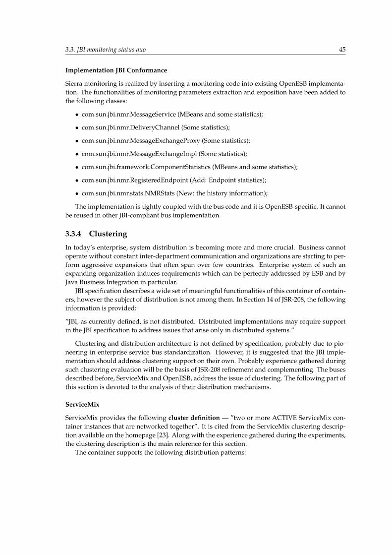
3.3. JBI monitoring status quo 45
Implementation JBI Conformance
Sierra monitoring is realized by inserting a monitoring code into existing OpenESB implementa-tion. The functionalities of monitoring parameters extraction and exposition have been added tothe following classes:
• com.sun.jbi.nmr.MessageService (MBeans and some statistics);
• com.sun.jbi.nmr.DeliveryChannel (Some statistics);
• com.sun.jbi.nmr.MessageExchangeProxy (Some statistics);
• com.sun.jbi.nmr.MessageExchangeImpl (Some statistics);
• com.sun.jbi.framework.ComponentStatistics (MBeans and some statistics);
• com.sun.jbi.nmr.RegisteredEndpoint (Add: Endpoint statistics);
• com.sun.jbi.nmr.stats.NMRStats (New: the history information);
The implementation is tightly coupled with the bus code and it is OpenESB-specific. It cannotbe reused in other JBI-compliant bus implementation.
3.3.4 Clustering
In today’s enterprise, system distribution is becoming more and more crucial. Business cannotoperate without constant inter-department communication and organizations are starting to per-form aggressive expansions that often span over few countries. Enterprise system of such anexpanding organization induces requirements which can be perfectly addressed by ESB and byJava Business Integration in particular.
JBI specification describes a wide set of meaningful functionalities of this container of contain-ers, however the subject of distribution is not among them. In Section 14 of JSR-208, the followinginformation is provided:
”JBI, as currently defined, is not distributed. Distributed implementations may require supportin the JBI specification to address issues that arise only in distributed systems.”
Clustering and distribution architecture is not defined by specification, probably due to pio-neering in enterprise service bus standardization. However, it is suggested that the JBI imple-mentation should address clustering support on their own. Probably experience gathered duringsuch clustering evaluation will be the basis of JSR-208 refinement and complementing. The busesdescribed before, ServiceMix and OpenESB, address the issue of clustering. The following part ofthis section is devoted to the analysis of their distribution mechanisms.
ServiceMix
ServiceMix provides the following cluster definition — ”two or more ACTIVE ServiceMix con-tainer instances that are networked together”. It is cited from the ServiceMix clustering descrip-tion available on the homepage [23]. Along with the experience gathered during the experiments,the clustering description is the main reference for this section.
The container supports the following distribution patterns:
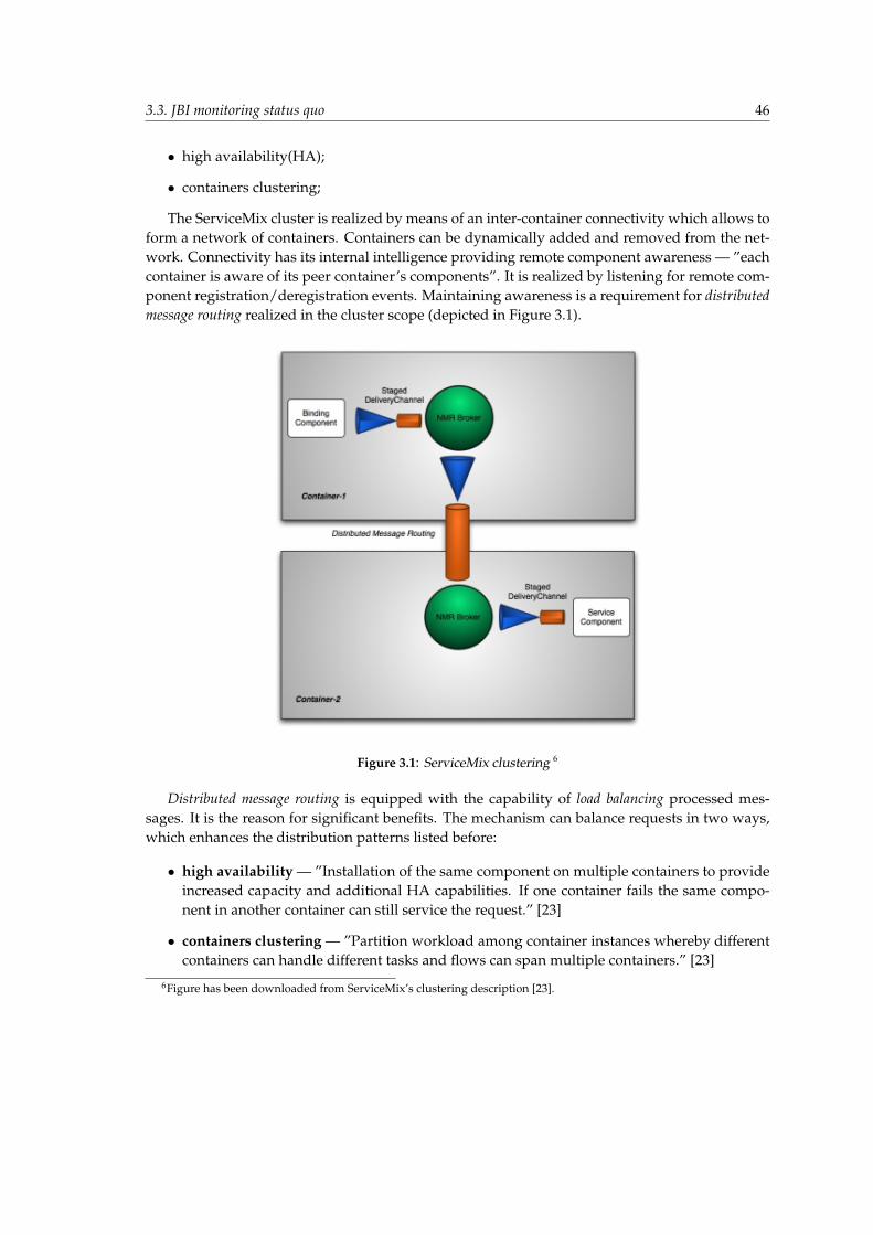
3.3. JBI monitoring status quo 46
• high availability(HA);
• containers clustering;
The ServiceMix cluster is realized by means of an inter-container connectivity which allows toform a network of containers. Containers can be dynamically added and removed from the net-work. Connectivity has its internal intelligence providing remote component awareness — ”eachcontainer is aware of its peer container’s components”. It is realized by listening for remote com-ponent registration/deregistration events. Maintaining awareness is a requirement for distributedmessage routing realized in the cluster scope (depicted in Figure 3.1).
Figure 3.1: ServiceMix clustering 6
Distributed message routing is equipped with the capability of load balancing processed mes-sages. It is the reason for significant benefits. The mechanism can balance requests in two ways,which enhances the distribution patterns listed before:
• high availability — ”Installation of the same component on multiple containers to provideincreased capacity and additional HA capabilities. If one container fails the same compo-nent in another container can still service the request.” [23]
• containers clustering — ”Partition workload among container instances whereby differentcontainers can handle different tasks and flows can span multiple containers.” [23]
6Figure has been downloaded from ServiceMix’s clustering description [23].
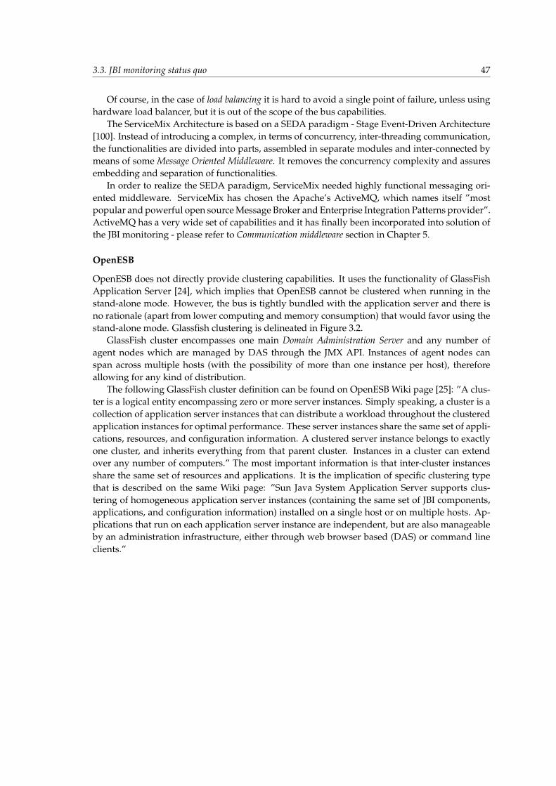
3.3. JBI monitoring status quo 47
Of course, in the case of load balancing it is hard to avoid a single point of failure, unless usinghardware load balancer, but it is out of the scope of the bus capabilities.
The ServiceMix Architecture is based on a SEDA paradigm - Stage Event-Driven Architecture[100]. Instead of introducing a complex, in terms of concurrency, inter-threading communication,the functionalities are divided into parts, assembled in separate modules and inter-connected bymeans of some Message Oriented Middleware. It removes the concurrency complexity and assuresembedding and separation of functionalities.
In order to realize the SEDA paradigm, ServiceMix needed highly functional messaging ori-ented middleware. ServiceMix has chosen the Apache’s ActiveMQ, which names itself ”mostpopular and powerful open source Message Broker and Enterprise Integration Patterns provider”.ActiveMQ has a very wide set of capabilities and it has finally been incorporated into solution ofthe JBI monitoring - please refer to Communication middleware section in Chapter 5.
OpenESB
OpenESB does not directly provide clustering capabilities. It uses the functionality of GlassFishApplication Server [24], which implies that OpenESB cannot be clustered when running in thestand-alone mode. However, the bus is tightly bundled with the application server and there isno rationale (apart from lower computing and memory consumption) that would favor using thestand-alone mode. Glassfish clustering is delineated in Figure 3.2.
GlassFish cluster encompasses one main Domain Administration Server and any number ofagent nodes which are managed by DAS through the JMX API. Instances of agent nodes canspan across multiple hosts (with the possibility of more than one instance per host), thereforeallowing for any kind of distribution.
The following GlassFish cluster definition can be found on OpenESB Wiki page [25]: ”A clus-ter is a logical entity encompassing zero or more server instances. Simply speaking, a cluster is acollection of application server instances that can distribute a workload throughout the clusteredapplication instances for optimal performance. These server instances share the same set of appli-cations, resources, and configuration information. A clustered server instance belongs to exactlyone cluster, and inherits everything from that parent cluster. Instances in a cluster can extendover any number of computers.” The most important information is that inter-cluster instancesshare the same set of resources and applications. It is the implication of specific clustering typethat is described on the same Wiki page: ”Sun Java System Application Server supports clus-tering of homogeneous application server instances (containing the same set of JBI components,applications, and configuration information) installed on a single host or on multiple hosts. Ap-plications that run on each application server instance are independent, but are also manageableby an administration infrastructure, either through web browser based (DAS) or command lineclients.”
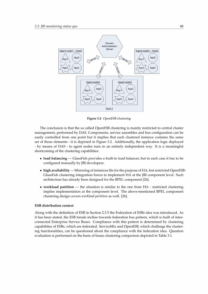
3.3. JBI monitoring status quo 48
Figure 3.2: OpenESB clustering
The conclusion is that the so called OpenESB clustering is mainly restricted to central clustermanagement, performed by DAS. Components, service assembles and bus configuration can beeasily controlled from one point but it implies that each clustered instance contains the sameset of those elements - it is depicted in Figure 3.2. Additionally, the application logic deployed- by means of DAS - to agent nodes runs in an entirely independent way. It is a meaningfulshortcoming of the clustering capabilities:
• load balancing — GlassFish provides a built-in load balancer, but in each case it has to beconfigured manually by JBI developers.
• high availability — Mirroring of instances fits for the purpose of HA, but restricted OpenESB-GlassFish clustering integration forces to implement HA at the JBI component level. Sucharchitecture has already been designed for the BPEL component [26].
• workload partition — the situation is similar to the one from HA - restricted clusteringimplies implementation at the component level. The above-mentioned BPEL componentclustering design covers workload partition as well. [26].
ESB distribution context
Along with the definition of ESB in Section 2.3.5 the Federation of ESBs idea was introduced. Asit has been stated, the ESB trends incline towards federation bus pattern, which is built of inter-connected Enterprise Service Buses. Compliance with this pattern is determined by clusteringcapabilities of ESBs, which are federated. ServiceMix and OpenESB, which challenge the cluster-ing functionalities, can be questioned about the compliance with the federation idea. Questionevaluation is performed on the basis of buses clustering comparison depicted in Table 3.1.
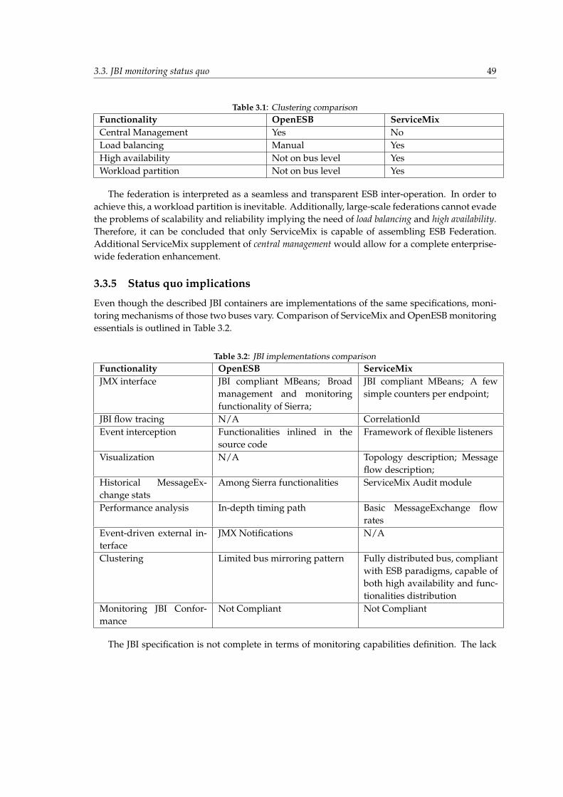
3.3. JBI monitoring status quo 49
Table 3.1: Clustering comparisonFunctionality OpenESB ServiceMixCentral Management Yes NoLoad balancing Manual YesHigh availability Not on bus level YesWorkload partition Not on bus level Yes
The federation is interpreted as a seamless and transparent ESB inter-operation. In order toachieve this, a workload partition is inevitable. Additionally, large-scale federations cannot evadethe problems of scalability and reliability implying the need of load balancing and high availability.Therefore, it can be concluded that only ServiceMix is capable of assembling ESB Federation.Additional ServiceMix supplement of central management would allow for a complete enterprise-wide federation enhancement.
3.3.5 Status quo implications
Even though the described JBI containers are implementations of the same specifications, moni-toring mechanisms of those two buses vary. Comparison of ServiceMix and OpenESB monitoringessentials is outlined in Table 3.2.
Table 3.2: JBI implementations comparisonFunctionality OpenESB ServiceMixJMX interface JBI compliant MBeans; Broad
management and monitoringfunctionality of Sierra;
JBI compliant MBeans; A fewsimple counters per endpoint;
JBI flow tracing N/A CorrelationIdEvent interception Functionalities inlined in the
source codeFramework of flexible listeners
Visualization N/A Topology description; Messageflow description;
Historical MessageEx-change stats
Among Sierra functionalities ServiceMix Audit module
Performance analysis In-depth timing path Basic MessageExchange flowrates
Event-driven external in-terface
JMX Notifications N/A
Clustering Limited bus mirroring pattern Fully distributed bus, compliantwith ESB paradigms, capable ofboth high availability and func-tionalities distribution
Monitoring JBI Confor-mance
Not Compliant Not Compliant
The JBI specification is not complete in terms of monitoring capabilities definition. The lack
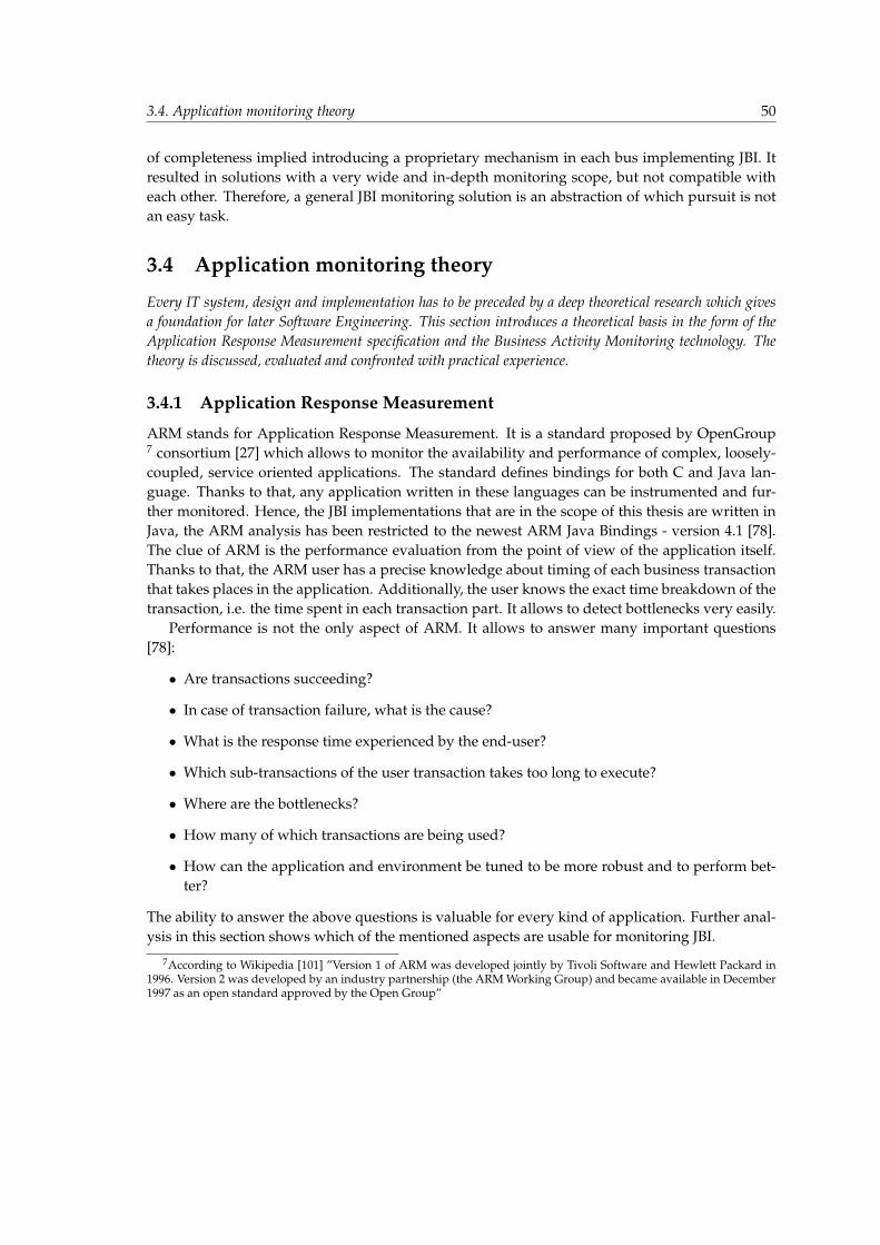
3.4. Application monitoring theory 50
of completeness implied introducing a proprietary mechanism in each bus implementing JBI. Itresulted in solutions with a very wide and in-depth monitoring scope, but not compatible witheach other. Therefore, a general JBI monitoring solution is an abstraction of which pursuit is notan easy task.
3.4 Application monitoring theory
Every IT system, design and implementation has to be preceded by a deep theoretical research which givesa foundation for later Software Engineering. This section introduces a theoretical basis in the form of theApplication Response Measurement specification and the Business Activity Monitoring technology. Thetheory is discussed, evaluated and confronted with practical experience.
3.4.1 Application Response Measurement
ARM stands for Application Response Measurement. It is a standard proposed by OpenGroup7 consortium [27] which allows to monitor the availability and performance of complex, loosely-coupled, service oriented applications. The standard defines bindings for both C and Java lan-guage. Thanks to that, any application written in these languages can be instrumented and fur-ther monitored. Hence, the JBI implementations that are in the scope of this thesis are written inJava, the ARM analysis has been restricted to the newest ARM Java Bindings - version 4.1 [78].The clue of ARM is the performance evaluation from the point of view of the application itself.Thanks to that, the ARM user has a precise knowledge about timing of each business transactionthat takes places in the application. Additionally, the user knows the exact time breakdown of thetransaction, i.e. the time spent in each transaction part. It allows to detect bottlenecks very easily.
Performance is not the only aspect of ARM. It allows to answer many important questions[78]:
• Are transactions succeeding?
• In case of transaction failure, what is the cause?
• What is the response time experienced by the end-user?
• Which sub-transactions of the user transaction takes too long to execute?
• Where are the bottlenecks?
• How many of which transactions are being used?
• How can the application and environment be tuned to be more robust and to perform bet-ter?
The ability to answer the above questions is valuable for every kind of application. Further anal-ysis in this section shows which of the mentioned aspects are usable for monitoring JBI.
7According to Wikipedia [101] ”Version 1 of ARM was developed jointly by Tivoli Software and Hewlett Packard in1996. Version 2 was developed by an industry partnership (the ARM Working Group) and became available in December1997 as an open standard approved by the Open Group”
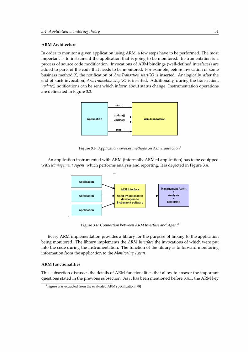
3.4. Application monitoring theory 51
ARM Architecture
In order to monitor a given application using ARM, a few steps have to be performed. The mostimportant is to instrument the application that is going to be monitored. Instrumentation is aprocess of source code modification. Invocations of ARM bindings (well-defined interfaces) areadded to parts of the code that needs to be monitored. For example, before invocation of somebusiness method X, the notification of ArmTransation.start(X) is inserted. Analogically, after theend of such invocation, ArmTransation.stop(X) is inserted. Additionally, during the transaction,update() notifications can be sent which inform about status change. Instrumentation operationsare delineated in Figure 3.3.
Figure 3.3: Application invokes methods on ArmTransaction8
An application instrumented with ARM (informally ARMed application) has to be equippedwith Management Agent, which performs analysis and reporting. It is depicted in Figure 3.4.
Figure 3.4: Connection between ARM Interface and Agent8
Every ARM implementation provides a library for the purpose of linking to the applicationbeing monitored. The library implements the ARM Interface the invocations of which were putinto the code during the instrumentation. The function of the library is to forward monitoringinformation from the application to the Monitoring Agent.
ARM functionalities
This subsection discusses the details of ARM functionalities that allow to answer the importantquestions stated in the previous subsection. As it has been mentioned before 3.4.1, the ARM key
8Figure was extracted from the evaluated ARM specification [78]
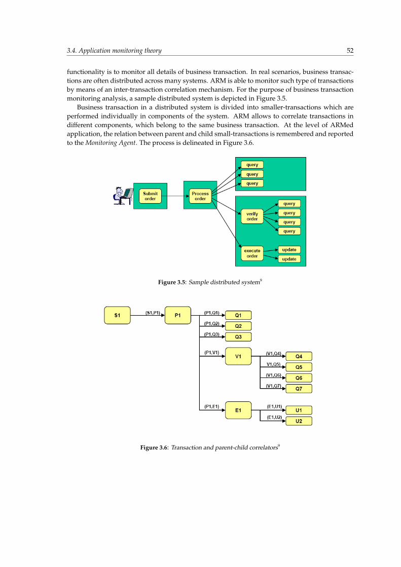
3.4. Application monitoring theory 52
functionality is to monitor all details of business transaction. In real scenarios, business transac-tions are often distributed across many systems. ARM is able to monitor such type of transactionsby means of an inter-transaction correlation mechanism. For the purpose of business transactionmonitoring analysis, a sample distributed system is depicted in Figure 3.5.
Business transaction in a distributed system is divided into smaller-transactions which areperformed individually in components of the system. ARM allows to correlate transactions indifferent components, which belong to the same business transaction. At the level of ARMedapplication, the relation between parent and child small-transactions is remembered and reportedto the Monitoring Agent. The process is delineated in Figure 3.6.
Figure 3.5: Sample distributed system9
Figure 3.6: Transaction and parent-child correlators9
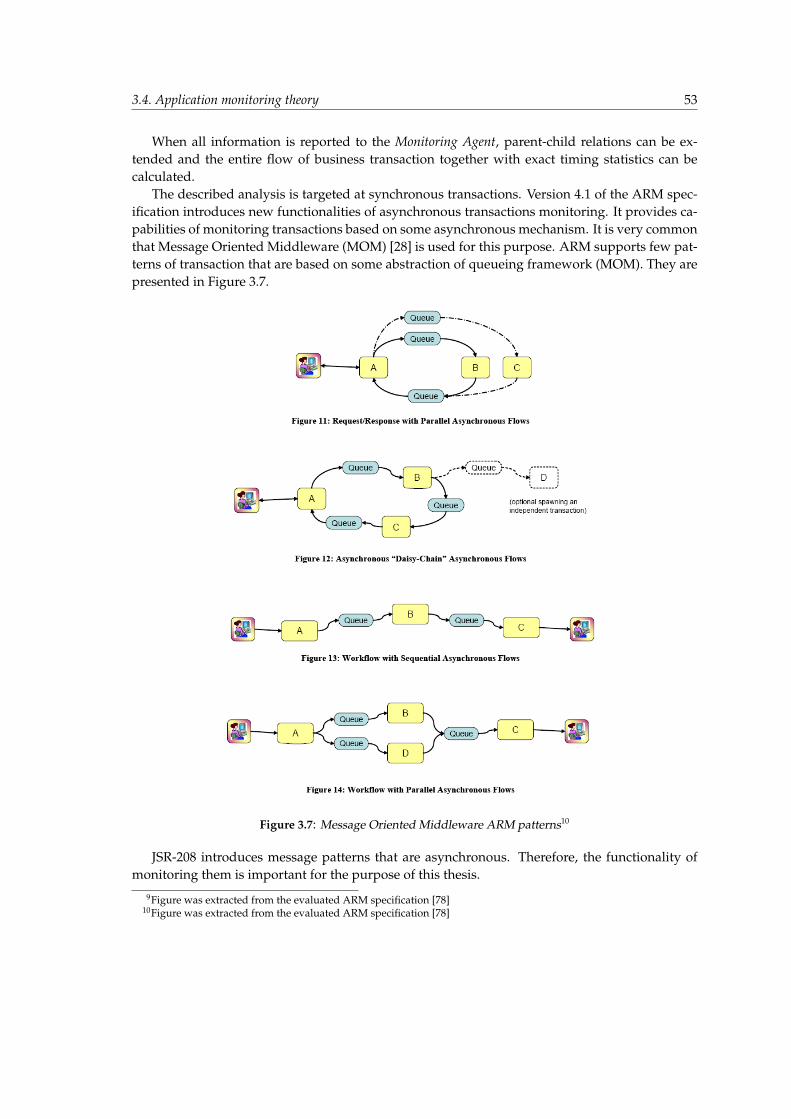
3.4. Application monitoring theory 53
When all information is reported to the Monitoring Agent, parent-child relations can be ex-tended and the entire flow of business transaction together with exact timing statistics can becalculated.
The described analysis is targeted at synchronous transactions. Version 4.1 of the ARM spec-ification introduces new functionalities of asynchronous transactions monitoring. It provides ca-pabilities of monitoring transactions based on some asynchronous mechanism. It is very commonthat Message Oriented Middleware (MOM) [28] is used for this purpose. ARM supports few pat-terns of transaction that are based on some abstraction of queueing framework (MOM). They arepresented in Figure 3.7.
Figure 3.7: Message Oriented Middleware ARM patterns10
JSR-208 introduces message patterns that are asynchronous. Therefore, the functionality ofmonitoring them is important for the purpose of this thesis.
9Figure was extracted from the evaluated ARM specification [78]10Figure was extracted from the evaluated ARM specification [78]

3.4. Application monitoring theory 54
OpenARM
This subsection evaluates available ARM implementations. Stable mature implementation is cru-cial for successful usage in JBI Monitoring.
Few commercial ARM implementation have been found:
• Exinda Networks [29];
• Oracle Siebel [30];
• IBM Tivoli’s WebSphere [31];
The evaluation of these implementations was impossible because using commercial solutionswas out of the scope of the thesis assumptions. Instead, focus was put on Open Source [32]implementations. Unfortunately, only one such implementation was available: OpenARM [33].OpenARM implements the Java part of ARM bindings and complies with version 4.0 of the spec-ification [77]. OpenARM’s implementation was initiated by Mark Masterson, who discoveredan absolute lack of reference and free implementations of ARM specification. He describes hismotivations in the following way: ”ARM itself is a pure specification. The Open Group does notprovide a reference implementation – they don’t provide any kind of implementation at all. Tradi-tionally, they have left that for the various commercial vendors who are members of the workinggroup. And there are a number of commercial, proprietary implementations of ARM, notablyfrom Tivoli and HP. These implementations are fairly expensive, however.” [34]. According toMasterson, OpenGroup makes the so called open specification but the lack of reference imple-mentation makes ARM less valuable. Masterson was forced to implement OpenARM relyingonly on the specification (and on his own previous ARM experience, of course).
Unfortunately, the quality of OpenARM is not comparable with commercial solutions. In theevaluation, a sample code from ARM specification was used, but in order to compile it againstOpenARM a modification has to be performed 11. Another shortcoming of OpenARM is the lackof compliance with version 4.1 of specification. OpenARM is relatively obsolete (last version wasreleased in 2005) and does not have functionalities for asynchronous transactions. It is a realshortcoming for the purpose of using it in the JBI monitoring.
ARM usefulness
The following facts gathered about ARM have impact on possible ARM usefulness:
• ARM provides the specification of Java interfaces but does not provide any reference imple-mentation.
• The only open source implementation - OpenARM lacks functionalities essential for JBI.
• The objective of full ARM compliance can be achieved only by first implementing it (it is, ofcourse, beyond the scope of this thesis).
• Successful implementation of ARM does not assure flexibility of exchanging it to some otherimplementation:
11Evaluation code is presented in Listing A.1
3.4. Application monitoring theory 55
– The lack of open source implementations of ARM 4.1.
– JBI’s messaging mechanism is a very specific case of asynchronous communicationsand there are aspects which have not been taken into account in the ARM design.Therefore, there is a risk of incompatibility between a self-implemented ARM andother third-party implementations.
The facts imply a high complexity of ARM usage. The main obstacle is the lack of mature im-plementation of ARM 4.1. In case of OpenARM being not sufficient, the most reasonable solutionseems to be:
• not implementing the ARM directly;
• not using the complex ARM interface definitions;
• deriving ARM ideas which introduce total new quality to application measurement;
• taking into account questions mentioned in Section 3.4.1;
3.4.2 Business Activity Monitoring
Business Activity Monitoring is another effort of standardizing or rather defining monitoring incontext of business and enterprise systems. On 1 April 2002, Gartner, Inc. [35] published anarticle entitled ”Business Activity Monitoring: Calm Before the Storm” [93], which introducedthe idea of BAM. The abbreviation stands for Business Activity Monitoring but it is also oftenreferred to as Business Activity Management. Gartner defines BAM as an extension to regularreal-time monitoring, which provides additional business oriented performance indicators. BAMis targeted at large, heterogeneous enterprise systems where information has to be gathered atmany levels, both internally and externally. Only such approach gives a complete view on thebusiness operations and processes, which BAM allows to monitor and manage. Even in 2002Gartner forecasted a rapid development of BAM: ”By 2004, BAM will grow to become the majorforce driving application integration’s deployment and benefits. Vendors will depend on BAMfor survival, and enterprises will tout BAM for its competitive advantage. BAM is the next bigthing that application integration vendors want and need.” Forecasts turned out to be true —today quick google search returns many commercial solutions which allow to integrate BAM intoexisting enterprise architecture. Some of them are listed below:
• Tibco Business Activity Monitoring Software12;
• Progress BAM13;
• Systar BusinessBridge ServiceVision14;
• WebMethods for Process, Infrastructure, B2B and SAP15;
• Adobe LiveCycle Business Activity Monitoring ES16;
12http://www.tibco.com/software/business activity monitoring/default.jsp13http://www.progress.com/psm/apama/business-activity-monitoring/index.ssp14http://www.systar.com/products/servicevision.asp15http://www.softwareag.com/Corporate/products/wm/bam/default.asp16http://www.adobe.com/products/livecycle/bam.html
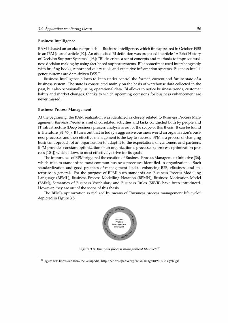
3.4. Application monitoring theory 56
Business Intelligence
BAM is based on an older approach — Business Intelligence, which first appeared in October 1958in an IBM Journal article [92]. An often cited BI definition was proposed in article ”A Brief Historyof Decision Support Systems” [96]: ”BI describes a set of concepts and methods to improve busi-ness decision making by using fact-based support systems. BI is sometimes used interchangeablywith briefing books, report and query tools and executive information systems. Business Intelli-gence systems are data-driven DSS.”
Business Intelligence allows to keep under control the former, current and future state of abusiness system. The state is constructed mainly on the basis of warehouse data collected in thepast, but also occasionally using operational data. BI allows to notice business trends, customerhabits and market changes, thanks to which upcoming occasions for business enhancement arenever missed.
Business Process Management
At the beginning, the BAM realization was identified as closely related to Business Process Man-agement. Business Process is a set of correlated activities and tasks conducted both by people andIT infrastructure (Deep business process analysis is out of the scope of this thesis. It can be foundin literature [81, 97]). It turns out that in today’s aggressive business world an organization’s busi-ness processes and their effective management is the key to success. BPM is a process of changingbusiness approach of an organization to adapt it to the expectations of customers and partners.BPM provides constant optimization of an organization’s processes (a process optimization pro-cess [104]) which allows to most effectively strive for its goals.
The importance of BPM triggered the creation of Business Process Management Initiative [36],which tries to standardize most common business processes identified in organizations. Suchstandardization and good practices of management lead to enhancing B2B, eBusiness and en-terprise in general. For the purpose of BPMI such standards as: Business Process ModellingLanguage (BPML), Business Process Modelling Notation (BPMN), Business Motivation Model(BMM), Semantics of Business Vocabulary and Business Rules (SBVR) have been introduced.However, they are out of the scope of this thesis.
The BPM’s optimization is realized by means of ”business process management life-cycle”depicted in Figure 3.8.
Figure 3.8: Business process management life-cycle17
17Figure was borrowed from the Wikipedia: http://en.wikipedia.org/wiki/Image:BPM-Life-Cycle.gif

3.4. Application monitoring theory 57
Monitoring is a very important phase of BPM cycle which triggers the real optimization pro-cess realized as re-orchestration of business processes. BAM used the BPM approach to orches-trate enterprise with event gathering mechanism, which resulted in the shortcoming of forcingthe enterprise to invest in BPM, before integrating BAM in the organization’s infrastructure. For-tunately, BAM evolved to use Complex Event Processing (CEP), which bring event detection andcorrelation to a higher quality level. Thanks to that, BAM dependency on BPM has been reduced.
Complex Event Processing
Complex Event Processing (CEP) is a relatively new solution capable of enhancing such technolo-gies as: BAM, BPM, EAI. According to CEP home site [37], the first bigger symposium on CEPsubject took place in March 2006, but it has greatly evolved until now.
CEP is targeted at enterprise applications and allows them to comprehend all of the informa-tion flowing through their IT infrastructure. CEP focuses on events that appear on various tiersof enterprise applications and allows to:
• intercept all events;
• filter out events that are out of concern and keep those which are valuable;
• detect complex multi-event patterns;
• enrich events with information of potential impact on higher management objectives;
• provide events correlation and abstraction;
• provide event hierarchies;
• provide event relationships such as causality, membership, timing and event-driven pro-cesses;
• report (act on) events in real time;
CEP goes deep into the enterprise infrastructure and allows to handle events produced by suchtechnologies as RFID [37, 105].
An example of using the CEP technology taken from the Wikipedia [105]: ”Car has several sen-sors - one that measures tire pressure, one that measures speed, and one that detects if someonesits on a seat or leaves a seat. The car is moving and the pressure of one of the tires moves from 45PSI to 41 PSI over 15 minutes. As the pressure in the tire is reducing, a series of events containingthe tire pressure is generated. In addition, a series of events containing the speed of the car isgenerated. The car’s Event Processor may detect a situation whereby a loss of tire pressure overa relatively long period of time results in the creation of the ’lossOfTirePresure’ event. This newevent may trigger a reaction process to note the pressure loss into the car’s maintenance log, andalert the driver via the car’s portal that the tire pressure has reduced.” This example delineatesthe basic functionalities realized by CEP: event interception, filtering, contextual interpretation,correlation and, finally, reporting.
3.4. Application monitoring theory 58
BAM
The fact that BI heavily depends on static data warehouses makes it inflexible to dynamic changes.BAM changes the approach and turns to real-time, event based data acquiring which can befurther aggregated, analysed and presented also in real-time [91]. BAM focuses on monitoringorganisation’s business activities both internal and external related to customers and partners.Such activity could be a business process (orchestrated by BPM) or more general organisation’sprocess which spans across multiple tiers and different applications. It also allows to monitortransactional resources such as Web services and message queues and thanks to Complex EventProcessing, correlate heterogeneous events that take place in context of those resources. BAMtargets to be useful for operation managers and upper management giving real-time status of allbusiness activities.
The basic functional steps of Business Activity Monitoring can be outlined in the followingway:
• gather the data from intercepted events;
• correlate events according to general patterns;
• aggregate the data according to general assumptions and user preferences;
• analyze the data;
• present the data in real time;
BAM has far more potential than the above-listed functionalities. It is a natural effect of en-hancing more static Business Intelligence to real-time monitoring. BI forces human interactionfor purpose of manual analysis of the collected and further processed data. It is required to con-clude and perform steps towards business activity modifications. BAM goes one step further andallows to define patterns and conditions, which are applied during the data processing. Whenthe condition is met, an alert is generated triggering notification about specific situation in thesystem. Additionally, an action can be bound to a condition which allows for a straight-forwardreaction to some diagnosed problems.
An exemplary scenario of BAM integration taken from the Wikipedia [103]: ”Mobile telecom-munications company is interested in detecting a situation whereby new customers are not set uppromptly and correctly on their network and within the various CRM and Billing solutions. Lowlevel technical events such as messages passing from one application to another over a middle-ware system, or transactions detected within a database logfile, are processed by a CEP engine.All event relating to an individual customer are correlated in order to detect an anomalous situ-ation whereby an individual customer has not been promptly or correctly provisioned, or set up.An alert can be generated to notify technical operations or to notify business operations, and thefailed provisioning step may be restarted automatically.”
The above scenario gives an idea of the power brought by Business Activity Monitoring. Thedescribed sample and strictly tailored functionality of detecting proper customers set up in CRMsand Billing solutions is not a feature that can be easily deployed. BAM extensions to BI implyhigher deployment difficulty. The advantage of strictly tailoring forces every organization willingto integrate BAM to resolve a specific case study which differs from one organization to another.In order to overcome this deployment issue, BAM experts identified some common templates

3.5. JBI Monitoring Challenge 59
that can be applied to well known scenarios: Banking, Manufacturing, Stoke Brokering [103].Nevertheless, the deployment complexity causes BAM adoption cost to increase.
3.5 JBI Monitoring Challenge
JBI Monitoring section (3.1) provided background for the thesis subject discussing various monitoring as-pects. The background going through the abstraction level, status quo and monitoring theory imposes quitestrict positioning of possible monitoring solutions that can be applied to the Java Business Integration. Thischapter discusses possible solution positioning and provides conclusions for a later architectural design.
3.5.1 JBI context influence
In order to discuss how deeply the background of JSR-208 and its evaluated implementationsinfluence the architectural possibilities, a JBI contextual analysis of monitoring abstraction is per-formed. As identified in Section 3.2, there are seven characteristics of monitoring system classifi-cation.
All of them can be applied straightforwardly to JBI apart from monitoring subject. In orderto apply this simple characteristic to JBI, the two types of monitoring approaches have to beevaluated in the context of JBI bus being the monitoring subject.
Monitoring subject characteristic
The JBI bus is a container for application logic deployed in the service units (introduced in Sec-tion (2.5)). Such relation can be interpreted as JBI bus being a system and service unit logic beingapplications. With such interpretations, the characteristic can be extrapolated to JBI, however mon-itoring parameters will be totally different. Examples of monitoring parameters in the system vs.application characteristic:
• system == JBI container — container uptime, total sent/received requests, total sent/re-ceived replies, total completed exchanges (consumed/provided), total error exchanges (con-sumed/provided), total number of activated endpoints, NMR performance;
• application == JBI business logic — endpoint uptime, first endpoint invocation TIMES-TAMP, last endpoint invocation TIMESTAMP, endpoint response time, business logic exe-cution performance, business faults statistics;
The proposed characteristic is not very formal, but has the advantage of flexible extrapolationsto a wide range of subjects, including JBI.
In the context of computer machine, the information gathered at the application level givesthe idea how the computer is usable to the final user. Application providers can have feedbackabout defects and shortcomings of their applications. In case of a serious error or performancedegradation at the application level, the administrator often has to consult system monitoringparameters to check for possible system failures. So for computer machines two roles can beidentified: system administrator and application provider. In Section 3.5 of JBI specification wecan find definitions of roles specific to JBI:
• Engine Developer — providers of Service Engines;
3.5. JBI Monitoring Challenge 60
• Binding Developer — providers of Binding Components;
• JBI Environment Provider — creator of JBI bus implementation;
• J2EE Platform Provider — administrator of a J2EE platform which hosts JBI in applicationserver environment;
• JBI Application Developer — Service Assembly providers which create business logic de-ployed to SE and external endpoint descriptors deployed to BC;
In the proposed characteristic, the system parameters would be in the first place valuable tothe JBI Environment Provider. Their can be also important for the J2EE Provider, who providesenvironment for JBI and probably wants to monitor and manage it. Developers of JBI Components- SE and BC - will benefit from both monitoring types. The system will provide the status oftheir components with bus interactions and application will inform about the results of serviceunits logic execution. The last role of the Application Developer will obviously benefit from theapplication monitoring type only. The fact that JBI roles are in line with the defined monitoringcharacteristic proves that it fits in JBI.
Monitoring abstraction evaluation
The JBI extrapolation of the monitoring subject characteristic allows to use a defined abstraction formeans of comparing: JBI specification, ServiceMix and OpenESB implementations. The followingcharacteristics of monitoring abstraction have been identified:
1. mechanism of information acquiring;
2. model of monitoring parameters evaluation;
3. mechanism of information exposition;
4. model of monitoring parameters exposition;
5. monitoring subject;
6. time context;
7. monitoring update delay;
The following table evaluates each of the above characteristics:
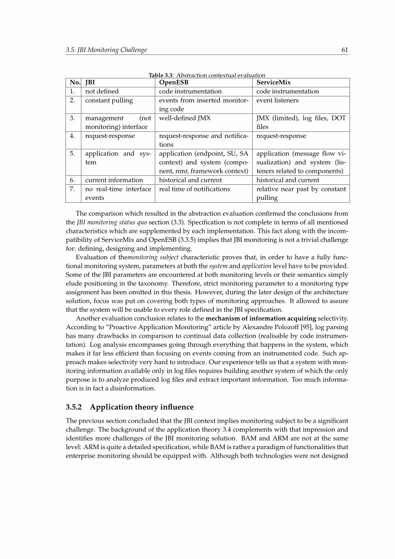
3.5. JBI Monitoring Challenge 61
Table 3.3: Abstraction contextual evaluationNo. JBI OpenESB ServiceMix1. not defined code instrumentation code instrumentation2. constant pulling events from inserted monitor-
ing codeevent listeners
3. management (notmonitoring) interface
well-defined JMX JMX (limited), log files, DOTfiles
4. request-response request-response and notifica-tions
request-response
5. application and sys-tem
application (endpoint, SU, SAcontext) and system (compo-nent, nmr, framework context)
application (message flow vi-sualization) and system (lis-teners related to components)
6. current information historical and current historical and current7. no real-time interface
eventsreal time of notifications relative near past by constant
pulling
The comparison which resulted in the abstraction evaluation confirmed the conclusions fromthe JBI monitoring status quo section (3.3). Specification is not complete in terms of all mentionedcharacteristics which are supplemented by each implementation. This fact along with the incom-patibility of ServiceMix and OpenESB (3.3.5) implies that JBI monitoring is not a trivial challengefor: defining, designing and implementing.
Evaluation of themonitoring subject characteristic proves that, in order to have a fully func-tional monitoring system, parameters at both the system and application level have to be provided.Some of the JBI parameters are encountered at both monitoring levels or their semantics simplyelude positioning in the taxonomy. Therefore, strict monitoring parameter to a monitoring typeassignment has been omitted in this thesis. However, during the later design of the architecturesolution, focus was put on covering both types of monitoring approaches. It allowed to assurethat the system will be usable to every role defined in the JBI specification.
Another evaluation conclusion relates to the mechanism of information acquiring selectivity.According to ”Proactive Application Monitoring” article by Alexandre Polozoff [95], log parsinghas many drawbacks in comparison to continual data collection (realisable by code instrumen-tation). Log analysis encompasses going through everything that happens in the system, whichmakes it far less efficient than focusing on events coming from an instrumented code. Such ap-proach makes selectivity very hard to introduce. Our experience tells us that a system with mon-itoring information available only in log files requires building another system of which the onlypurpose is to analyze produced log files and extract important information. Too much informa-tion is in fact a disinformation.
3.5.2 Application theory influence
The previous section concluded that the JBI context implies monitoring subject to be a significantchallenge. The background of the application theory 3.4 complements with that impression andidentifies more challenges of the JBI monitoring solution. BAM and ARM are not at the samelevel: ARM is quite a detailed specification, while BAM is rather a paradigm of functionalities thatenterprise monitoring should be equipped with. Although both technologies were not designed
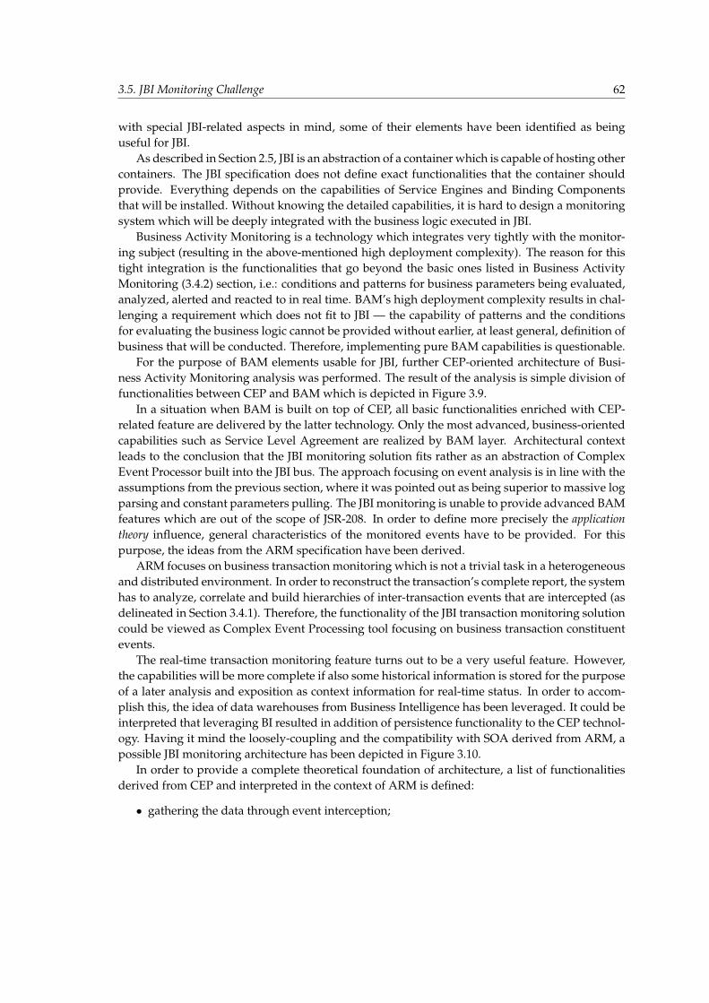
3.5. JBI Monitoring Challenge 62
with special JBI-related aspects in mind, some of their elements have been identified as beinguseful for JBI.
As described in Section 2.5, JBI is an abstraction of a container which is capable of hosting othercontainers. The JBI specification does not define exact functionalities that the container shouldprovide. Everything depends on the capabilities of Service Engines and Binding Componentsthat will be installed. Without knowing the detailed capabilities, it is hard to design a monitoringsystem which will be deeply integrated with the business logic executed in JBI.
Business Activity Monitoring is a technology which integrates very tightly with the monitor-ing subject (resulting in the above-mentioned high deployment complexity). The reason for thistight integration is the functionalities that go beyond the basic ones listed in Business ActivityMonitoring (3.4.2) section, i.e.: conditions and patterns for business parameters being evaluated,analyzed, alerted and reacted to in real time. BAM’s high deployment complexity results in chal-lenging a requirement which does not fit to JBI — the capability of patterns and the conditionsfor evaluating the business logic cannot be provided without earlier, at least general, definition ofbusiness that will be conducted. Therefore, implementing pure BAM capabilities is questionable.
For the purpose of BAM elements usable for JBI, further CEP-oriented architecture of Busi-ness Activity Monitoring analysis was performed. The result of the analysis is simple division offunctionalities between CEP and BAM which is depicted in Figure 3.9.
In a situation when BAM is built on top of CEP, all basic functionalities enriched with CEP-related feature are delivered by the latter technology. Only the most advanced, business-orientedcapabilities such as Service Level Agreement are realized by BAM layer. Architectural contextleads to the conclusion that the JBI monitoring solution fits rather as an abstraction of ComplexEvent Processor built into the JBI bus. The approach focusing on event analysis is in line with theassumptions from the previous section, where it was pointed out as being superior to massive logparsing and constant parameters pulling. The JBI monitoring is unable to provide advanced BAMfeatures which are out of the scope of JSR-208. In order to define more precisely the applicationtheory influence, general characteristics of the monitored events have to be provided. For thispurpose, the ideas from the ARM specification have been derived.
ARM focuses on business transaction monitoring which is not a trivial task in a heterogeneousand distributed environment. In order to reconstruct the transaction’s complete report, the systemhas to analyze, correlate and build hierarchies of inter-transaction events that are intercepted (asdelineated in Section 3.4.1). Therefore, the functionality of the JBI transaction monitoring solutioncould be viewed as Complex Event Processing tool focusing on business transaction constituentevents.
The real-time transaction monitoring feature turns out to be a very useful feature. However,the capabilities will be more complete if also some historical information is stored for the purposeof a later analysis and exposition as context information for real-time status. In order to accom-plish this, the idea of data warehouses from Business Intelligence has been leveraged. It could beinterpreted that leveraging BI resulted in addition of persistence functionality to the CEP technol-ogy. Having it mind the loosely-coupling and the compatibility with SOA derived from ARM, apossible JBI monitoring architecture has been depicted in Figure 3.10.
In order to provide a complete theoretical foundation of architecture, a list of functionalitiesderived from CEP and interpreted in the context of ARM is defined:
• gathering the data through event interception;
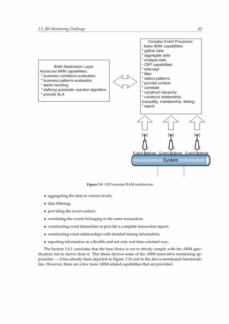
3.5. JBI Monitoring Challenge 63
Figure 3.9: CEP-oriented BAM architecture
• aggregating the data at various levels;
• data filtering;
• providing the event context;
• correlating the events belonging to the same transaction;
• constructing event hierarchies to provide a complete transaction report;
• constructing event relationships with detailed timing information;
• reporting information in a flexible and not only real-time-oriented way;
The Section 3.4.1 concludes that the best choice is not to strictly comply with the ARM spec-ification, but to derive from it. This thesis derives some of the ARM innovative monitoring ap-proaches — it has already been depicted in Figure 3.10 and in the above-mentioned functionali-ties. However, there are a few more ARM-related capabilities that are provided:
3.6. Conclusion 64
Figure 3.10: Possible Architecture Positioning
• Monitoring transaction success and, in case of failure, reporting the reason;
• Transaction timing along with a complete timing breakdown across component;
• The ease of finding bottlenecks;
• Support for both synchronous and asynchronous distributed transactions;
• Minimization of influence of (slowing down) the application being monitored;
• Preserving the loosely-coupled architecture between the ARM application nodes and the ARMmonitoring center(it is called ARM Agent in the ARM specification);
3.6 Conclusion
This chapter provided a deep insight into the subject of monitoring enterprise applications and JBI in par-ticular and it allowed to grasp significant conclusions. First of all, the monitoring abstraction section iden-tified that there is no general enterprise monitoring theory that could serve as a foundation for GlassBus. Itforced the authors to introduce a substitution in form of general monitoring characteristics which allow toevaluate the JBI monitoring status quo. It turned out that JSR-208 proposes only restricted management
3.6. Conclusion 65
interface and lacks a significant standardization of monitoring facilities. Additionally, the specificationfinds the distribution and clustering as being out of the scope of JBI version 1.0. It implies that OpenESBand ServiceMix implementations differ in clustering mechanisms and monitoring facilities.
Further analysis of the application monitoring theory resulted in the conclusion that neither BAM norARM can be directly used in the monitoring of JBI. The lack of mature open-source implementation of Ap-plication Response Measurement was the reason for restriction to extracting most valuable ARM ideas andincorporating them into the JBI monitoring solution in a proprietary way. Business Activity monitoringturned out to be too demanding in terms of the monitoring capabilities oriented at business analysis - ad-vanced triggers, alarms and instant reactions. It has been concluded that the presented monitoring solutionshould rather be based on the concept of Complex Event Processor (CEP), which is in fact a mechanism forconducting the BAM functionalities. The presented monitoring application theory allowed to grasp mainideas and directions of enterprise monitoring. It enables to create awell-designed, functional and flexiblesolution of which architecture principles cannot be rejected without denying fundamentals of ApplicationResponse Measurement and Business Activity Monitoring.
The last section of this chapter introduced the assumptions of a system compliant with the ideas ofARM and providing CEP functionalities. It identified the JBI monitoring as a significant challenge - theconstraints resulting from the JBI status quo and the application monitoring theory were found as beingnot trivial.
Chapter 4
Executive summary of the monitoring architecture
I think it is an immutable law in business that words are words, explanations are explanations, promisesare promises - but only performance is reality. Harold S.Geneen, an American Accountant and Indus-trialist.
4.1 Preamble
Previous chapters outlined a complete background of the problem discussed in this paper. Second chapter (2)presented the fundamentals of an enterprise integration theory as well as introduced the standardized ESBin form of JBI. Not only did the third chapter (3) explain the purpose of JBI monitoring, but it also inspectedits current status quo. Finally, some basic concepts of the JBI monitoring architecture were formed.
The main goal of the current chapter is to elucidate and develop these concepts in order to presentexecutive summary of the JBI monitoring architecture. Concepts are discussed with reference to previouschapters forming a consistent view of the designed solution. Functional and non-functional requirementsare means of expression, which makes the message explicit and well-defined. The main emphasis is put onthe performance and the compliance with JBI.
Next section introduces the final solution called GlassBus whose main goal is fulfillment of requirementsmentioned above. Its brief description is followed by the architectural diagram which depicts the monitoringtopology. At the end short description of each GlassBus element is provided.
Finally, a monitoring abstraction is presented. It contains a thorough explanation of notions and con-cepts introduced by GlassBus in order to provide a full understanding of JBI monitoring fundamentals. Themost important aspect is the definition and demarcation of the business transaction - top-level entity whichis monitored.
4.2 Problem definition
General purpose of the presented thesis is to design and implement monitoring solution compli-ant with JBI. However, this sentence does not clarify the architectural details as well as particularfunctionalities which are required in the final solution. At the beginning of the work, it wasimpossible to estimate what monitoring features are practicable. The process of requirements en-gineering was performed in order to design the characteristics of the system . It consisted of fivestages [64]:
• environment evaluation - analyzing the JBI specification in order to gain thorough knowl-edge;
• requirements elicitation - gathering the requirements from JBI community;
4.2. Problem definition 67
• analysis - checking for consistency and completeness;
• specification - documenting the requirements;
• verification - making sure the specified requirements are correct;
As a result, main concepts of the system are presented in form of the functional and non-functionalrequirements. ”It is a statement that identifies a necessary attribute, capability, characteristic, orquality of a system in order for it to have value and utility to a user.” [75]. It is worth mentioningthat presented requirements were used as input during the design stages of development whichare described in the fifth chapter (5). The description of the requirements is brief as it is only ashortened summary of the features which were already introduced or are described in detail lateron.
4.2.1 Non-functional requirements
Non-functional requirements are the constraints or quality requirements. Other terms for non-functional requirements are ”quality attributes”, ”quality goals” and ”quality of service require-ments”. They specify criteria that can be used to judge the operation of a system. Summing up,they define how a system is supposed to be [66].
JBI Compliance
The implementation of the monitoring mechanisms should be based only on APIs defined in JBI.No proprietary features should be enclosed by the target solution. The general assumption is thatthe system should be able to monitor any kind of JBI-compliant ESBs.
Performance-oriented implementation
Any kind of significant deterioration of JBI performance should NOT be noticeable during theoperation of the monitoring system. High performance is one of the key aspects since it has agreat impact on the business efficiency. Implementation should consist of as little computationlogic as possible, every construct has to be well-considered and performance-oriented.
Loosely coupled architecture
Elements of the monitoring system should be loosely-coupled due to the following reasons:
• It is the best way of monitoring of loosely-coupled applications.
• It is the requirement of ARM, described in Section 3.4.1.
Runtime environment support
It should be possible to run the final solution on the application server as well as in the stand-alonemode. It ensures that the system is reusable under all environmental conditions.
4.2. Problem definition 68
Non-invasiveness for the code of JBI
Designed architecture should on no account invade the JBI code. It is not possible to apply codechanges, recompile the code and produce substitute binaries. Operation of the monitoring systemshould be transparent from the point of view of JBI container.
Simplicity
The usage of monitoring system should be simple and straightforward. Initial installation shouldconsist of default settings in order to provide the working configuration as quick as possible.It does not mean that the system should lack sophisticated and advanced functionalities. Theyshould be, however, configurable according to the principle of abstraction.
Usefulness for JBI community
Monitoring system should be innovative and useful for the community of JBI users. There is nogoal in implementing a product which is similar to all the others. Due to deficiency, any kind ofmonitoring solutions for JBI are highly anticipated. However, this fact should not deteriorate itsquality.
The ease of finding bottlenecks
One of the main goals of the monitoring solution is to enable the JBI administrator to tune the per-formance of the business transactions executed in JBI environment. APIs as well as mechanismsshould be implemented in compliance with this requirement to form advantageous platform foroptimization of business processing.
High manageability
Accomplishing of an administrative task should be easy to perform. The system should be easyto maintain and manage.
Avoid ”Not Invented Here” syndrom
”Not Invented Here” (NIH) [67] also called as ”reinventing the wheel” is a term which describes aonerous software culture that avoids reusing existing products which come from different vendoror products family. Efforts which are split up usually result in a group of identical softwaredistributions differing only in a slight manner. During implementation every requirement fora software feature has to be carefully evaluated in order to find a robust, tested and supportedsoftware library. Own proprietary code has to be omitted unless a fundamental need exists.
Architecture accordant with ”best-practices” of software design
Best-practice [53] is a technique which introduces a general, reusable and effective solutions to acommonly known tasks. It assumes that with the usage of proper, most efficient methodology acompetitive outcome can be brought with as few drawbacks as possible. Best practices of softwaredesign should be applied during the development of the monitoring solution. That induces:
4.2. Problem definition 69
• usage of commonly-known, recommended solutions;
• usage of specified tools, templates and libraries;
• usage of design patterns;
• writing of a qualitative code;
Open-source dependencies
Straightforward requirement which oblige the authors to use only software artifacts which arereleased as Open Source 1.
Use of monitoring capabilities defined in JSR
JSR-208 specification defines a set of JMX beans which provide a basic knowledge about condi-tions and qualities of operating JBI. In compliance with the NIH requirement it makes no senseto implement it once more. Designed solution should benefit from all contributive techniquesdefined in JBI, no matter how technically sophisticated they are.
4.2.2 Functional requirements
Functional requirements describe the functionalities of the system as concrete functions whichthe system is able to execute. They can consist of diagrams, technical details, data manipulationand processing charts in order to specify particular behaviors of the solution. Summing up, theydescribe what the system is supposed to do [58].
Completeness of monitoring capabilities
Monitoring capabilities of the system should not be limited by anything different from the JBIspecification itself. The selection of underlying technologies and architectural decisions is sup-posed to be careful and well-considered in order not to constrain, but to provide the system witha wide variety of possibilities.
Parameters for application and system monitoring types
Requirement characterizes two classes of monitoring parameters which the system should pro-vide:
• application parameters;
• system parameters;
They are described meticulously in Section 3.5.1.
1Open Source - http://en.wikipedia.org/wiki/Open source movement
4.2. Problem definition 70
Real-time and historical data
Requirement specifies two kinds of monitoring data which should be made accessible by thesolution:
• real-time data;
• historical data;
The system should continuously evaluate the conditions and qualities of JBI providing the userwith real-time metrics as well as aggregated historical analysis from the specified time interval.
Topology and flow information
Requirement defines two types of events that the system has to track. Not only should it analyzethe information about message exchanges which flow in the bus, but it should also follow alltopology changes of the runtime environment.
Notifications
The system should encompass the mechanism of notifying the subscribed users about specifiedconditions or alert-situations which are agreed-upon. It is similar to the mechanism introducedby OpenESB (Section: 3.3.3). This functionality allows to conduct business activity monitoring(BAM) described in Section 3.4.2.
Support for synchronous and asynchronous operations
JBI supports synchronous and asynchronous operations in the MessageExchange processing (sendand sendSync methods). The system should be able to monitor and profile both of these interac-tion patterns.
Transaction monitoring
All transactions should be precisely monitored in order to provide the full spectrum of metricsconcerning business processing . Stored pieces of information should concern:
• parties which took part in the transaction;
• information flow;
• exact timing path: business processing time, time spent in queues, etc.;
• result: success or failure;
It is compliant with ARM transaction monitoring described in Chapter 3.4.1.
Clustering requirements
On the one hand, JBI does not standardize the clustering of buses. On the other hand, manyproprietary mechanisms exist as OpenESB supports clustering/mirroring, while ServiceMix in-troduces federation of JBI elements. All these facts should be taken under consideration duringthe design stage in order to support both clustering scenarios.
4.3. Introducing GlassBus 71
Monitoring parameters extending those proposed in OpenESB
OpenESB introduces a long description of monitoring mechanism enclosed in the Sierra2 3 4 re-lease. Not only should the final solution derive from it but it should also extend its capabilities.
Event listeners based on the proprietary solution introduced in ServiceMix
ServiceMix provides a functionality of event interception, which is described in Section 3.3.2.However, this mechanism is not compliant with JBI, since it relies on definition of events listen-ers provided in package org.apache.servicemix.jbi.event. The system should reimplement thisfeature in compliance with JBI.
CorrelationId mechanism from ServiceMix
SeriveMix is the only implementation of JBI specification5, which defines the mechanism of mes-sage correlation. This mechanism combines the features of ARM (Section 3.4.1) as well as CEP(Section 3.4.2). It is one of the most anticipated features in the final solution.
4.3 Introducing GlassBus
Section 3.5.2 outlined some basic concepts of the generic monitoring architecture compliant withJBI. In order to propose an initial point of reference, a first draft of the monitoring solution ispresented in Figure 4.1. Its name is GlassBus. The name is not coincidental since it fits well tothe group of Glass-like solutions (GlassBox6, GlassFish7, etc.). The main goal of GlassBus is thefulfillment of requirements described above.GlassBus defines three types of elements which form the monitoring topology:
• Monitoring Agent - sensor of the system - implementation of the Event Listener whichencompasses some functionalities of the Complex Event Processor (both terms introducedin Chapter 3.5.2);
• Monitoring Engine - brain of the system - implementation of the ARM monitoring center(3.10); its main goals are:
– reception of the data sent by Monitoring Agents;
– storage of the data in the data-store;
– exposition of the processed monitoring data to external clients;
• Communication Backbone - enables Monitoring Agents and Engines to communicate in aloosely-coupled manner;
The description of GlassBus architecture is brief. It is only an overview of the concepts which areextended in the subsequent chapters.
2http://wiki.open-esb.java.net/Wiki.jsp?page=SierraUpdateRuntimeMonitoring3http://wiki.open-esb.java.net/Wiki.jsp?page=SierraStatisticsPresentation4http://wiki.open-esb.java.net/Wiki.jsp?page=SierraMBeanNotifications5ServiceMix is based on JBI, but it is not certified to be fully JBI compliant.6GlassBox - Troubleshooting agent for Java applications - http://www.glassbox.com/7GlassFish - Open Source Application Server - https://glassfish.dev.java.net/;
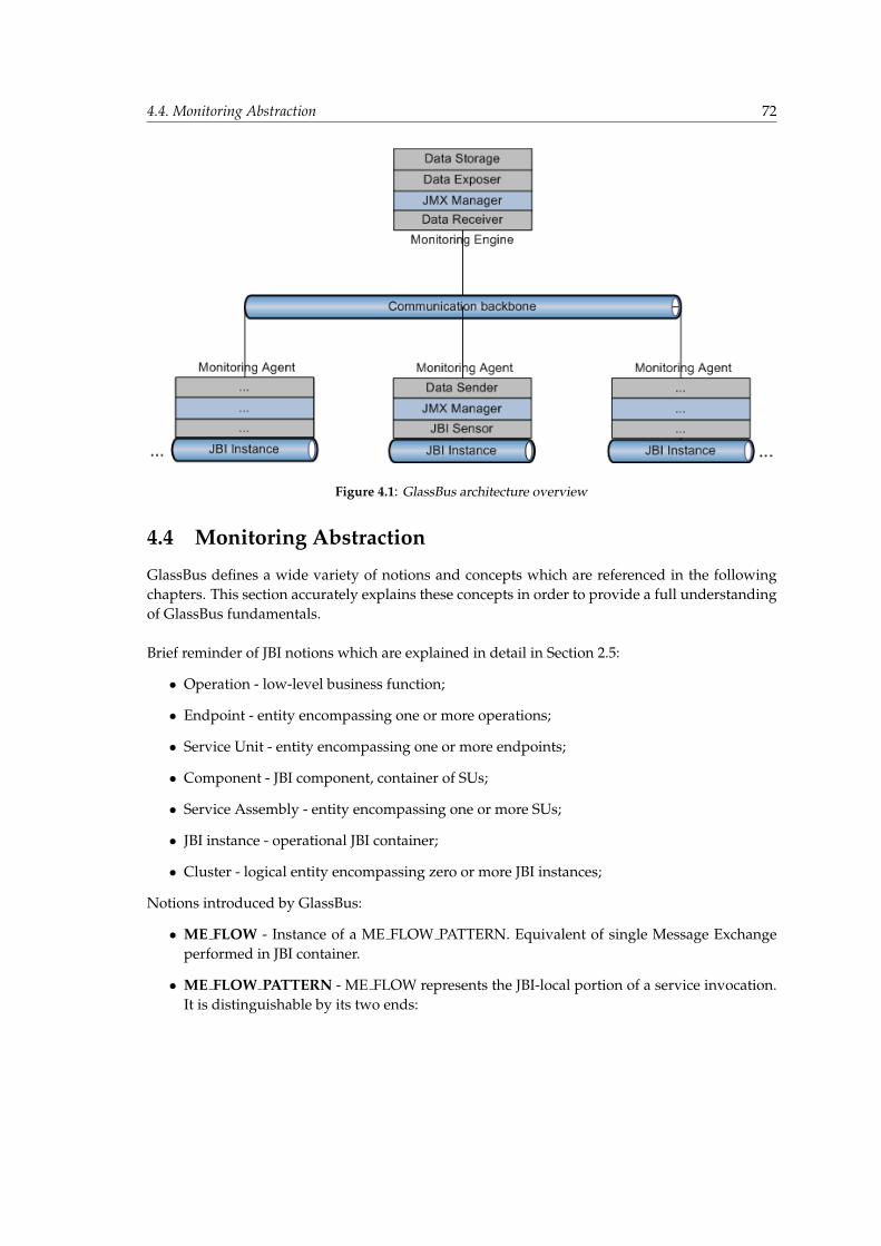
4.4. Monitoring Abstraction 72
Figure 4.1: GlassBus architecture overview
4.4 Monitoring Abstraction
GlassBus defines a wide variety of notions and concepts which are referenced in the followingchapters. This section accurately explains these concepts in order to provide a full understandingof GlassBus fundamentals.
Brief reminder of JBI notions which are explained in detail in Section 2.5:
• Operation - low-level business function;
• Endpoint - entity encompassing one or more operations;
• Service Unit - entity encompassing one or more endpoints;
• Component - JBI component, container of SUs;
• Service Assembly - entity encompassing one or more SUs;
• JBI instance - operational JBI container;
• Cluster - logical entity encompassing zero or more JBI instances;
Notions introduced by GlassBus:
• ME FLOW - Instance of a ME FLOW PATTERN. Equivalent of single Message Exchangeperformed in JBI container.
• ME FLOW PATTERN - ME FLOW represents the JBI-local portion of a service invocation.It is distinguishable by its two ends:
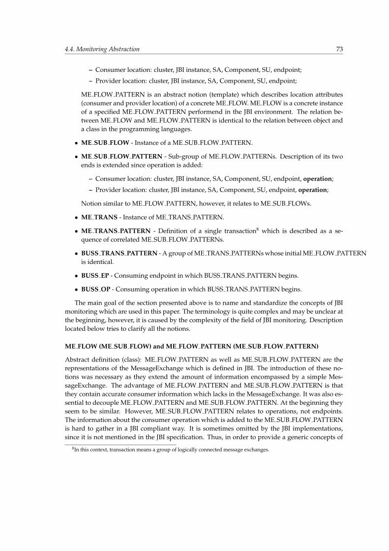
4.4. Monitoring Abstraction 73
– Consumer location: cluster, JBI instance, SA, Component, SU, endpoint;
– Provider location: cluster, JBI instance, SA, Component, SU, endpoint;
ME FLOW PATTERN is an abstract notion (template) which describes location attributes(consumer and provider location) of a concrete ME FLOW. ME FLOW is a concrete instanceof a specified ME FLOW PATTERN performend in the JBI environment. The relation be-tween ME FLOW and ME FLOW PATTERN is identical to the relation between object anda class in the programming languages.
• ME SUB FLOW - Instance of a ME SUB FLOW PATTERN.
• ME SUB FLOW PATTERN - Sub-group of ME FLOW PATTERNs. Description of its twoends is extended since operation is added:
– Consumer location: cluster, JBI instance, SA, Component, SU, endpoint, operation;
– Provider location: cluster, JBI instance, SA, Component, SU, endpoint, operation;
Notion similar to ME FLOW PATTERN, however, it relates to ME SUB FLOWs.
• ME TRANS - Instance of ME TRANS PATTERN.
• ME TRANS PATTERN - Definition of a single transaction8 which is described as a se-quence of correlated ME SUB FLOW PATTERNs.
• BUSS TRANS PATTERN - A group of ME TRANS PATTERNs whose initial ME FLOW PATTERNis identical.
• BUSS EP - Consuming endpoint in which BUSS TRANS PATTERN begins.
• BUSS OP - Consuming operation in which BUSS TRANS PATTERN begins.
The main goal of the section presented above is to name and standardize the concepts of JBImonitoring which are used in this paper. The terminology is quite complex and may be unclear atthe beginning, however, it is caused by the complexity of the field of JBI monitoring. Descriptionlocated below tries to clarify all the notions.
ME FLOW (ME SUB FLOW) and ME FLOW PATTERN (ME SUB FLOW PATTERN)
Abstract definition (class): ME FLOW PATTERN as well as ME SUB FLOW PATTERN are therepresentations of the MessageExchange which is defined in JBI. The introduction of these no-tions was necessary as they extend the amount of information encompassed by a simple Mes-sageExchange. The advantage of ME FLOW PATTERN and ME SUB FLOW PATTERN is thatthey contain accurate consumer information which lacks in the MessageExchange. It was also es-sential to decouple ME FLOW PATTERN and ME SUB FLOW PATTERN. At the beginning theyseem to be similar. However, ME SUB FLOW PATTERN relates to operations, not endpoints.The information about the consumer operation which is added to the ME SUB FLOW PATTERNis hard to gather in a JBI compliant way. It is sometimes omitted by the JBI implementations,since it is not mentioned in the JBI specification. Thus, in order to provide a generic concepts of
8In this context, transaction means a group of logically connected message exchanges.

4.4. Monitoring Abstraction 74
JBI monitoring, these two terms were decoupled. Figures 4.2 and 4.3 depict presented concepts.
Lifecycle:
• ME FLOW PATTERN, as well as ME SUB FLOW PATTERN, begins when the correspond-ing MessageExchange is initially sent (passed to NMR using one of the send methods by acomponent).
• ME FLOW PATTERN, as well as ME SUB FLOW PATTERN, terminates when the corre-sponding MessageExchange terminate.
Concrete definition (object): ME FLOW as well as ME SUB FLOW are the concrete instances ofthe patterns mentioned above. For example: ME FLOW NR1 was performed at 01.54PM andlasted 13,2seconds.
Figure 4.2: ME FLOW PATTERN example
Figure 4.3: ME SUB FLOW PATTERN example
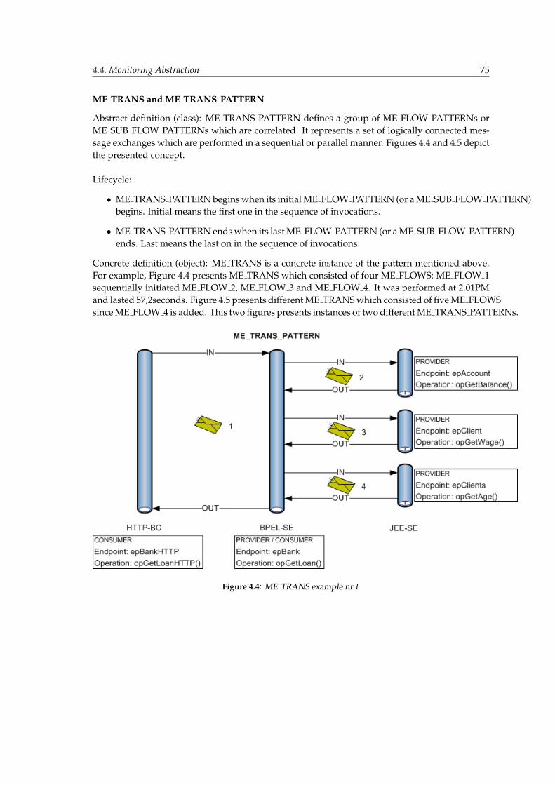
4.4. Monitoring Abstraction 75
ME TRANS and ME TRANS PATTERN
Abstract definition (class): ME TRANS PATTERN defines a group of ME FLOW PATTERNs orME SUB FLOW PATTERNs which are correlated. It represents a set of logically connected mes-sage exchanges which are performed in a sequential or parallel manner. Figures 4.4 and 4.5 depictthe presented concept.
Lifecycle:
• ME TRANS PATTERN begins when its initial ME FLOW PATTERN (or a ME SUB FLOW PATTERN)begins. Initial means the first one in the sequence of invocations.
• ME TRANS PATTERN ends when its last ME FLOW PATTERN (or a ME SUB FLOW PATTERN)ends. Last means the last on in the sequence of invocations.
Concrete definition (object): ME TRANS is a concrete instance of the pattern mentioned above.For example, Figure 4.4 presents ME TRANS which consisted of four ME FLOWS: ME FLOW 1sequentially initiated ME FLOW 2, ME FLOW 3 and ME FLOW 4. It was performed at 2.01PMand lasted 57,2seconds. Figure 4.5 presents different ME TRANS which consisted of five ME FLOWSsince ME FLOW 4 is added. This two figures presents instances of two different ME TRANS PATTERNs.
Figure 4.4: ME TRANS example nr.1
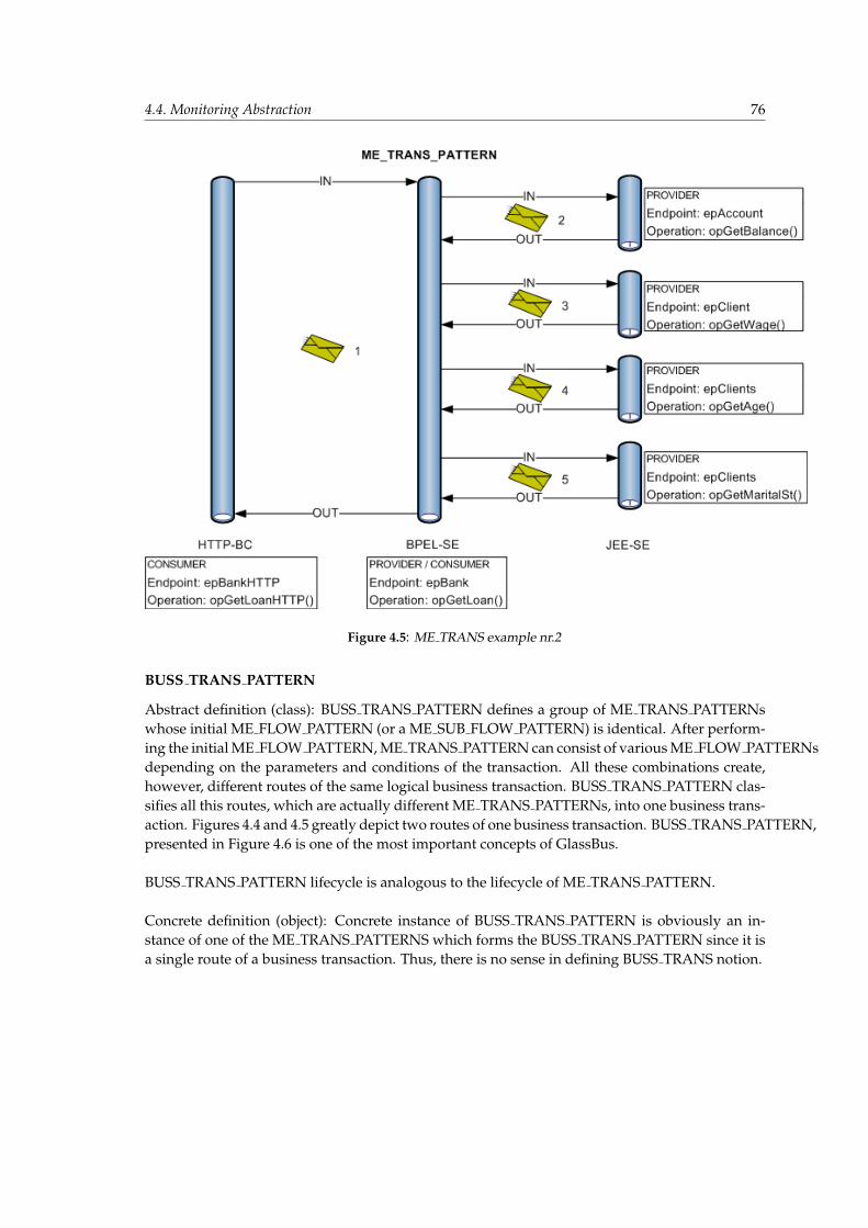
4.4. Monitoring Abstraction 76
Figure 4.5: ME TRANS example nr.2
BUSS TRANS PATTERN
Abstract definition (class): BUSS TRANS PATTERN defines a group of ME TRANS PATTERNswhose initial ME FLOW PATTERN (or a ME SUB FLOW PATTERN) is identical. After perform-ing the initial ME FLOW PATTERN, ME TRANS PATTERN can consist of various ME FLOW PATTERNsdepending on the parameters and conditions of the transaction. All these combinations create,however, different routes of the same logical business transaction. BUSS TRANS PATTERN clas-sifies all this routes, which are actually different ME TRANS PATTERNs, into one business trans-action. Figures 4.4 and 4.5 greatly depict two routes of one business transaction. BUSS TRANS PATTERN,presented in Figure 4.6 is one of the most important concepts of GlassBus.
BUSS TRANS PATTERN lifecycle is analogous to the lifecycle of ME TRANS PATTERN.
Concrete definition (object): Concrete instance of BUSS TRANS PATTERN is obviously an in-stance of one of the ME TRANS PATTERNS which forms the BUSS TRANS PATTERN since it isa single route of a business transaction. Thus, there is no sense in defining BUSS TRANS notion.
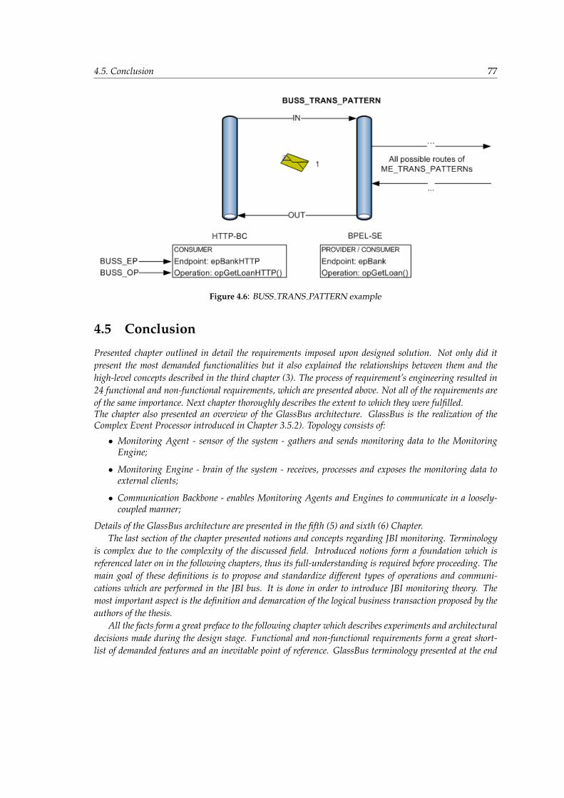
4.5. Conclusion 77
Figure 4.6: BUSS TRANS PATTERN example
4.5 Conclusion
Presented chapter outlined in detail the requirements imposed upon designed solution. Not only did itpresent the most demanded functionalities but it also explained the relationships between them and thehigh-level concepts described in the third chapter (3). The process of requirement’s engineering resulted in24 functional and non-functional requirements, which are presented above. Not all of the requirements areof the same importance. Next chapter thoroughly describes the extent to which they were fulfilled.The chapter also presented an overview of the GlassBus architecture. GlassBus is the realization of theComplex Event Processor introduced in Chapter 3.5.2). Topology consists of:
• Monitoring Agent - sensor of the system - gathers and sends monitoring data to the MonitoringEngine;
• Monitoring Engine - brain of the system - receives, processes and exposes the monitoring data toexternal clients;
• Communication Backbone - enables Monitoring Agents and Engines to communicate in a loosely-coupled manner;
Details of the GlassBus architecture are presented in the fifth (5) and sixth (6) Chapter.The last section of the chapter presented notions and concepts regarding JBI monitoring. Terminology
is complex due to the complexity of the discussed field. Introduced notions form a foundation which isreferenced later on in the following chapters, thus its full-understanding is required before proceeding. Themain goal of these definitions is to propose and standardize different types of operations and communi-cations which are performed in the JBI bus. It is done in order to introduce JBI monitoring theory. Themost important aspect is the definition and demarcation of the logical business transaction proposed by theauthors of the thesis.
All the facts form a great preface to the following chapter which describes experiments and architecturaldecisions made during the design stage. Functional and non-functional requirements form a great short-list of demanded features and an inevitable point of reference. GlassBus terminology presented at the end

4.5. Conclusion 78
enables the authors to precisely communicate the message using an agreed-upon, fully-understandablenotions.
Chapter 5
GlassBus Research
A theory is something nobody believes, except the person who made it. An experiment is something every-body believes, except the person who made it. Albert Einstein, German born American Physicist.
5.1 Preamble
The previous chapter (4) provided a glimpse of the GlassBus architecture. Main functionalities and ex-pectations were described in form of the functional and non-functional requirements. In order to providebest-fitting architectural solutions which are compliant with these requirements, a wide set of experimentswas performed. Experiments were made at every design stage, whenever a nontrivial problem was faced.These kind of development methodology is sometimes referred to in the literature as Experimental DrivenDevelopment. Every experiment was thoroughly documented and it consisted of: a general description,research results and the discussion regarding requirements compliance of the chosen realization.
The list presented below outlines the description and goal of each experiment conducted during theprocess of design and development.
• Information acquiring mechanism - Clarifies the way in which GlassBus will instrument the JBI busin order to gather monitoring information from running instances.
• JBI monitoring mechanisms - Defines the set of monitoring capabilities of GlassBus as well as ex-plains the underlying mechanisms.
• Correlation heuristics - Defines the methods of business transaction identification and monitoringthanks to the mechanism of ME FLOW’s correlation.
• Persistence - Investigates the newest persistence solutions. Experiment consists of three parts:database engine choice, persistence layer choice, persistence domain design.
• Communication middleware - Determines the best communication method for GlassBus in order toprovide the interconnect among GlassBus elements on agreed-upon conditions.
• Management middleware - Designs the specification, interface and implementation of the manage-ment mechanism for GlassBus which is accordant with best-practices, for example, composite 1 designpattern.
• Hierarchical Data Management - The problem of hierarchical data management is not trivial in Java.There is no standardized library which copes with all the possible problems and requirements. Dueto that fact, a thoughtful examination is performed in order to choose the best solution of hierarchicaldata management in GlassBus.
• Installation and runtime environment - Provides the simplest and most robust solution of GlassBusinstallation and configuration which supports both: stand-alone and in-container execution.
1Composite design pattern - http://en.wikipedia.org/wiki/Composite pattern
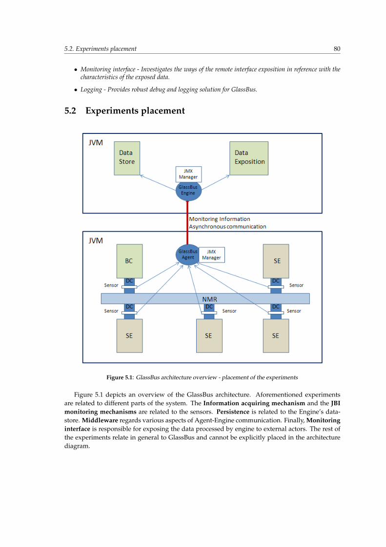
5.2. Experiments placement 80
• Monitoring interface - Investigates the ways of the remote interface exposition in reference with thecharacteristics of the exposed data.
• Logging - Provides robust debug and logging solution for GlassBus.
5.2 Experiments placement
Figure 5.1: GlassBus architecture overview - placement of the experiments
Figure 5.1 depicts an overview of the GlassBus architecture. Aforementioned experimentsare related to different parts of the system. The Information acquiring mechanism and the JBImonitoring mechanisms are related to the sensors. Persistence is related to the Engine’s data-store. Middleware regards various aspects of Agent-Engine communication. Finally, Monitoringinterface is responsible for exposing the data processed by engine to external actors. The rest ofthe experiments relate in general to GlassBus and cannot be explicitly placed in the architecturediagram.
5.3. Information acquiring mechanism 81
5.3 Information acquiring mechanism
This experiment is related to one of the monitoring classification characteristics introduced in Sec-tion 3.2 — mechanism for acquiring monitoring information. It is a fundamental building blockof every monitoring system and GlassBus is no exception here. Flexibility of this mechanismgives the foundation to a wide range of the JBI monitoring capabilities: MessageExchange inter-ception, correlation and topology tracing, which allows to supersede the monitoring features ofServiceMix and OpenESB.
The crucial assumption is that the mechanism must not modify the source of the chosen buses:ServiceMix and OpenESB. Any modification would result in the solution being not useful for theJBI community because every user would be forced to patch the source code and recompile thewhole bus.
5.3.1 Possible options
The Section 3.2 defines the following kinds of mechanisms for acquiring information:
• log analysis;
• code instrumentation;
Only the log analysis is non-invasive for the code of bus, but it does not comply with otherrequirements. Information does not have to be logged in real time (there can be some undefineddelay). Therefore, the real-time requirement may not be met. Processing logs is not efficient - aperformance problem. But the most significant problem results from the lack of a logging formatstandardization. Each bus would need a proprietary mechanism for parsing and interpretinglogs (the verbosity of which has to be accordingly tuned and the information of which could befar from completeness) — that would be unacceptable. Therefore, the only reasonable choice wascode instrumentation, which complied with every requirement apart from being non-invasive forthe source code and thus being not useful for JBI buses communities.
The problem is solved by the code instrumentation applied through Aspect Oriented Pro-gramming, which was introduced for the first time in the article ”Aspect-Oriented Programming”published by Kiczales et al. in 1997 [90]. The article provides the following AOP goal definition:”The goal of Aspect-Oriented Programming (AOP) is to make it possible to deal with crosscuttingaspects of a system’s behaviour as separately as possible.” The JBI aspect that GlassBus needs tocrosscut is of course monitoring - AOP fits into GlassBus’s demands. The crosscutting can be per-formed on join points, being an abstraction of points in a program’s control flow. AOP introducespointcuts for the purpose of the join points set specification. The aspect framework provides vari-ous criteria that can be used to specify what join points are within the scope of a particular pointcut.Finally, advice are introduced allowing to execute some code (aspect logic) in the join points definedby the pointcuts (i.e. in the context of pointcuts). In the AOP terminology: the advice of the aspectlogic is applied to the code in the pointcut scope, which can execute in a before, after or aroundmanner. The combination of the pointcuts, advice and some additional logic forms an aspect whichis the primary AOP modular entity used for crosscutting various system concerns. These are onlythe very basics of Aspect Oriented Programming (inspired by AspectJ Programming Guide [80]),the details of which are assumed to be known to the reader of this thesis.
5.3. Information acquiring mechanism 82
The code gathered in the aspect has to be applied to the original program code and such anoperation is called weaving. According to ”The AspectJ Development Environment Guide” [109],weaving can be applied in three different ways:
• Compile-time (source) — must be used when the aspect modifies the original program andother code parts rely on this modification. Weaving other than compile-time will result in acompile error.
• Post-compile (binary) — class files (or whole JARs) are modified during weaving process.
• Load-time — ”binary weaving deferred until the point that a class loader loads a class fileand defines the class to the JVM” [109].
The only weaving type complying with all requirements is load-time, which allows to apply thecode instrumentation in runtime — just before the bus starts. Therefore, a modification of the bussource or binary is not needed.
5.3.2 Realisation
AspectJ is the most mature and powerful AOP framework for Java and therefore it has been cho-sen for the purpose of the GlassBus’s monitoring aspect. In order to enable load-time weaving,AspectJ provides an appropriate agent in the form of a jar file that has to be given as an argumentto the JVM invocation - -javaagent:pathto/aspectjweaver.jar. Weaving is achieved by overridingJVM’s class loader and appropriately changing the bytecode of the loaded classes, which are inweaving scope. The agent waits for jars in classpath that contain the META-INF/aop.xml file,which provides configuration for the aspects enclosed in a particular jar. Sample aop.xml is avail-able in Listing A.8. It defines packages that are included in the weaving scope, aspect names, i.e.fully qualified class names of the aspects as well as concrete aspects which extend the abstractaspects provided in the jar. Defining concrete aspects at the XML level provides a very flexiblemechanism of adjusting the aspect’s details which can be environment-dependant — it is suitedto the needs of adapting aspects to two different JBI implementations.
The described monitoring aspect does not make any assumptions about the crosscut imple-mentation, apart from the JBI compliance. The pointcuts on the well-defined JBI interfaces areperfectly enough for intercepting all needed information appearing in any bus that is JBI compli-ant. Further pointcuts details are provided in Section 5.4, while the rest of this section focuses ondescription of the aspect weaving configuration in ServiceMix and OpenESB.
ServiceMix
ServiceMix has recently been adopted to several Application Servers: JBoss, Geronimo and Tom-cat, but the immaturity level of those adoptions did not allow to maintain all functionalities ofthe stand-alone mode, which is currently the most common ServiceMix deployment scenario.Therefore, the GlassBus solution focuses on supporting the ServiceMix stand-alone scenario.
The weaver file - aspectjweaver.jar - is placed in ServiceMix’s lib directory along with jarscontaining the aspects. The final step requires a modification of the servicemix.bat, which is thebus’s startup script. The JVM invocation has to be modified accordingly:
"%JAVA%" "-javaagent:%SERVICEMIX_HOME%\lib\aspectjweaver.jar" ...
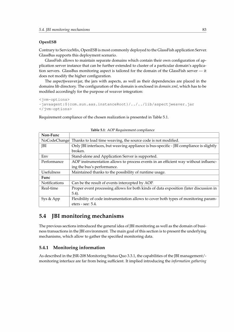
5.4. JBI monitoring mechanisms 83
OpenESB
Contrary to ServiceMix, OpenESB is most commonly deployed to the GlassFish application Server.GlassBus supports this deployment scenario.
GlassFish allows to maintain separate domains which contain their own configuration of ap-plication server instance that can be further extended to cluster of a particular domain’s applica-tion servers. GlassBus monitoring aspect is tailored for the domain of the GlassFish server — itdoes not modify the higher configuration.
The aspectjweaver.jar, the jars with aspects, as well as their dependencies are placed in thedomains lib directory. The configuration of the domain is enclosed in domain.xml, which has to bemodified accordingly for the purpose of weaver integration:
<jvm-options>-javaagent:${com.sun.aas.instanceRoot}/../../lib/aspectjweaver.jar</jvm-options>
Requirement compliance of the chosen realization is presented in Table 5.1.
Table 5.1: AOP Requirement complianceNon-FuncNoCodeChange Thanks to load time weaving, the source code is not modified.JBI Only JBI interfaces, but weaving appliance is bus-specific - JBI compliance is slightly
broken.Env Stand-alone and Application Server is supported.Performance AOP instrumentation allows to process events in an efficient way without influenc-
ing the bus’s performance.Usefulness Maintained thanks to the possibility of runtime usage.FuncNotifications Can be the result of events intercepted by AOP.Real-time Proper event processing allows for both kinds of data exposition (later discussion in
5.4).Sys & App Flexibility of code instrumentation allows to cover both types of monitoring param-
eters - see: 5.4.
5.4 JBI monitoring mechanisms
The previous sections introduced the general idea of JBI monitoring as well as the domain of busi-ness transactions in the JBI environment. The main goal of this section is to present the underlyingmechanisms, which allow to gather the specified monitoring data.
5.4.1 Monitoring information
As described in the JSR-208 Monitoring Status Quo 3.3.1, the capabilities of the JBI management/-monitoring interface are far from being sufficient. It implied introducing the information gathering

5.4. JBI monitoring mechanisms 84
mechanism depicted in Section 5.3. In order to provide a complete gathering mechanism, a defini-tion of JBI points that will be crosscut by the aspects has to be supplied. This section provides adefinition of those points which are referred to as pointcuts in the AOP terminology.
The pointcuts and the accompanying advice are grouped into aspects. GlassBus-Agent’s as-pects are divided into two groups: messaging interception and topology interception.
Messaging interception
Careful analysis of the JBI specification allowed to identify the elements related to messaging.As it has been depicted in Section 2.5, the crucial communication element of a bus is NMR -Normalized Message Router, which provides functionalities of normalization, denormalizationand, of course, routing. The JBI components have to directly interact with NMR and for thispurpose they are equipped with the Delivery Channel, which is specified by regular Java interface.It allows to define pointcuts which rely only on the provided interface of the Delivery Channel.Such pure JBI pointcuts are the GlassBus’s essentials, which provide the elegance of not bind-ing to specific OpenESB and ServiceMix implementation and restrict to relying only on JBI, thusproviding innovative monitoring solution fully compliant with JSR-208.
Each method of the Delivery Channel has been crosscut resulting in the following pointcuts(ME - MessageExchange, DC - DeliveryChannel):
pointcut accept(DC): execution(ME accept());pointcut acceptTimeout(timeout, DC): execution(ME accept(long));pointcut send(ME, DC): execution(void send(ME));pointcut sendSync(ME, DC): execution(boolean sendSync(ME));pointcut sendSyncTimeout(ME,long,DC): execution(boolean sendSync(ME, long));
Unfortunately, in the process of the development it turned out that the ServiceMix’s Deliv-eryChannel implementation is not fully compliant with JSR. It introduces one additional method:processInbound, which allows to inject MEs into the channel in a ”push” manner. It is equiva-lent to the accept method, which receives the message in a ”pull” manner. In order to overcomethis noncompliance, GlassBus leverages AspectJ’s flexible mechanism of extending abstract as-pects. The above-mentioned pointcuts are enriched with an abstract pointcut called pushAcceptand enclosed in the JBIMessagingInterceptor aspect (the code is provided in Listing A.4). GlassBusprovides separate concrete versions of the JBIMessagingInterceptor dedicated to each JBI imple-mentation. Concrete aspect is provided by means of the aop.xml file mentioned in the previoussection 5.3. The aop.xml configuration for ServiceMix is provided in Listing A.8, while OpenESB’sis presented in Listing (A.9). A detailed AOP configuration of GlassBus artifacts will be describedin Chapter 6.
Such solution allows to support both OpenESB and ServiceMix without denying full JBI com-pliance.
Messaging pointcuts are advised in an around manner. It allows to trace the parameter statebefore and after a particular method invocation. Additionally, every JBIException occurring inDeliveryChannel can be intercepted and appropriate notification can be sent to GlassBus-Engine.It obviously supersedes the capabilities of ServiceMix’s messaging listeners which do not coverthe exceptions interception.
The processing of each ME interception is aligned with the knowledge about topology - deliv-ery channel being the invocation subject is checked every time against channels registered during
5.4. JBI monitoring mechanisms 85
the initialization and starting(accordingly init and start method of ComponentLifeCycle interface)of the JBI components. MessageExchanges acquired from the pointcuts are subjected to correla-tion heuristics described in the next section (5.5), which allow to join separate MEs into flows ofbusiness transactions. The described basic JBI pointcuts are sufficient for the needs of the moni-toring parameters presented earlier.
Topology interception
The JBI’s topology state changes occasionally. Therefore, its dynamics cannot be compared withthe dynamics of the messaging events. JBI JMX interfaces expose information about topologybut their usage forces to constant interfaces pulling and listening for changes. As it has beenmentioned in Chapter 3, such approach is undesirable. It implies motivation for emerging asmart topology interception by means of AOP.
Topology interception has been enclosed in two aspects: JBITopologyComponentInterceptor(ListingA.5) and JBITopologySUInterceptor (Listing A.6). The first aspect focuses on tracing the bus’s com-ponents. It is realized by crosscutting all methods of theComponentLifeCycle interface, thus allow-ing for intercepting the following component state changes: init, start, stop and shutdown.
Thanks to that, GlassBus acquires information about every change in the bus’s Binding Com-ponents and Service Engines.The JBITopologySUInterceptor focuses on artifacts deployed to the JBI components, which encom-pass: ServiceAssemblys (SA), ServiceUnits (SU) and Endpoints. Every JBI component shouldimplement a Component interface (cf. SPI in Section 2.5) which provides setters and getters forthe ServiceUnitManager - an entity that every JBI component is equipped with. ServiceUnitMan-ager crosscutting allows to intercept all events related to service units including: deploy, init,shutDown, start, stop and undeploy.
After intercepting an SU event, it has to be correlated with parent ServiceAssembly. Unfortu-nately, it was impossible to achieve it through an SA event interception. In order to discover theparent SA, the JBI’s DeploymentServiceMBean has to be used:
1. List of ServiceAssemblies deployed to the bus has to be retrieved using the getDeployed-ServiceAssemblies().
2. For each SA the descriptor is acquired by means of the getServiceAssemblyDescriptormethod. The descriptor is the jbi.xml file described in specification. It has to be parsedin order to extract compounding Service Units.
3. Name of the considered SU is matched to extracted Service Units, which allows to discoverparent Service Assembly.
The JBITopologySUInterceptor aspect has its internal registry which is used to remember andupdate relations between SA and SU. It reduces the need of redundant Service Assemblies’ de-scriptors parsing. Of course, finally the relations are propagated to Engine and stored in a hierar-chical data model along with the rest of the topology information.
The described logic covers SA, SU and their correlation. In order to intercept a complete topol-ogy view, information about internal and external JBI endpoints is needed. Each endpoint is
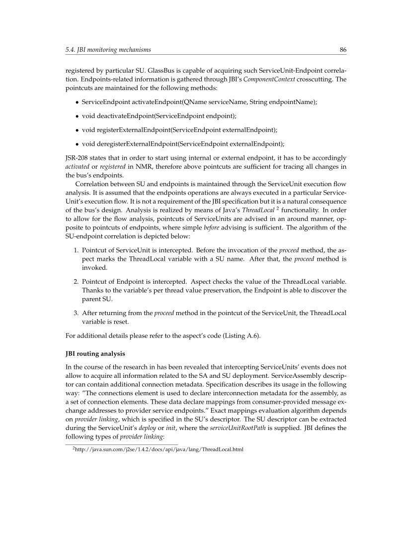
5.4. JBI monitoring mechanisms 86
registered by particular SU. GlassBus is capable of acquiring such ServiceUnit-Endpoint correla-tion. Endpoints-related information is gathered through JBI’s ComponentContext crosscutting. Thepointcuts are maintained for the following methods:
• ServiceEndpoint activateEndpoint(QName serviceName, String endpointName);
• void deactivateEndpoint(ServiceEndpoint endpoint);
• void registerExternalEndpoint(ServiceEndpoint externalEndpoint);
• void deregisterExternalEndpoint(ServiceEndpoint externalEndpoint);
JSR-208 states that in order to start using internal or external endpoint, it has to be accordinglyactivated or registered in NMR, therefore above pointcuts are sufficient for tracing all changes inthe bus’s endpoints.
Correlation between SU and endpoints is maintained through the ServiceUnit execution flowanalysis. It is assumed that the endpoints operations are always executed in a particular Service-Unit’s execution flow. It is not a requirement of the JBI specification but it is a natural consequenceof the bus’s design. Analysis is realized by means of Java’s ThreadLocal 2 functionality. In orderto allow for the flow analysis, pointcuts of ServiceUnits are advised in an around manner, op-posite to pointcuts of endpoints, where simple before advising is sufficient. The algorithm of theSU-endpoint correlation is depicted below:
1. Pointcut of ServiceUnit is intercepted. Before the invocation of the proceed method, the as-pect marks the ThreadLocal variable with a SU name. After that, the proceed method isinvoked.
2. Pointcut of Endpoint is intercepted. Aspect checks the value of the ThreadLocal variable.Thanks to the variable’s per thread value preservation, the Endpoint is able to discover theparent SU.
3. After returning from the proceed method in the pointcut of the ServiceUnit, the ThreadLocalvariable is reset.
For additional details please refer to the aspect’s code (Listing A.6).
JBI routing analysis
In the course of the research in has been revealed that intercepting ServiceUnits’ events does notallow to acquire all information related to the SA and SU deployment. ServiceAssembly descrip-tor can contain additional connection metadata. Specification describes its usage in the followingway: ”The connections element is used to declare interconnection metadata for the assembly, asa set of connection elements. These data declare mappings from consumer-provided message ex-change addresses to provider service endpoints.” Exact mappings evaluation algorithm dependson provider linking, which is specified in the SU’s descriptor. The SU descriptor can be extractedduring the ServiceUnit’s deploy or init, where the serviceUnitRootPath is supplied. JBI defines thefollowing types of provider linking:
2http://java.sun.com/j2se/1.4.2/docs/api/java/lang/ThreadLocal.html
5.5. Correlation heuristics 87
• Standard links — The NMR performs its normal routing, including the application of ser-vice connections. The evaluation algorithm is simple:
1. If the destination is set to existing endpoint, connections are ignored and ME is sent tothat endpoint.
2. If the destination endpoint does not exist, connections are looked up in order to mapthe endpoint to the real destination.
• Hard links — The consumer always specifies the endpoint of a provider directly, and therouting is not affected by service connections.
• Soft links — The consumer always specifies the endpoint of a provider using an indirectaddress defined in the connections.
GlassBus is capable of acquiring ServiceAssembly connections metadata and taking it into ac-count in the JBI transactions tracking described in the next section.Requirement compliance of the chosen realization is presented in Table 5.3.
Table 5.2: JBI parameters requirement complianceNon-FuncJBI All monitoring parameters (apart from small exceptions) are acquired by the JBI-
compliant crosscutting and analysis.Usefulness Monitoring parameters completeness and capabilities supremacy implies that Glass-
Bus solution is desirable and usable for JBI communities.JSR-based Some MBeans defined in JSR-208 are used to acquire the complete monitoring infor-
mationSimplicity Monitoring parameters list provides a simple JBI knowledge summaryFuncParameters GlassBus provides all acquirable information about JBI’s messaging and topology,
which are more complete than combined ServiceMix and OpenESB monitoring pa-rameters and cover both thesystem and application monitoring classification charac-teristics.
Topology&Flow Both completely covered thanks to the JBI pointcutsSend/ASync Both types of MessageExchange patterns are intercepted by messaging pointcuts.ME Result Thanks to exceptions interception, both success and failure of the MEs and the entire
transactions can be monitored.Cluster JBI scope of Cluster is covered by monitoring parameters listSMix Events GlassBus interception supersedes ServiceMix’s - exceptions monitoring
5.5 Correlation heuristics
As described in Section 4.4, a group of logically correlated Message Exchanges (ME FLOWs)forms a business transaction. The main goal of this experiment was to design, test and imple-ment mechanism compliant with JBI which would provide GlassBus with the functionality of thevery ME FLOW correlation.

5.5. Correlation heuristics 88
5.5.1 Problem definition
Message Correlation is the concept of tying messages together. Usually it occurs when one ser-vice calls another services during a longer business processing. The calls are logically coupled butphysically decoupled. The usage of correlation ids to track the flow of logically related messagesis a commonly used mechanism in systems based on messaging middleware. Generally corre-lation is a specification of a group of markers encompassed by messages and a set of messagingactions which specify how the processing should carry and preserve the unique values of thesemarkers that were initialized by the first message [65]. On the one hand, JBI does not introduceany kind of hierarchical relations for Message Exchanges that depend on the invocation tree. Onthe other hand, message correlation was one of the most important functional requirements ofGlassBus as it combines the key features of business transaction monitoring introduced by ARM(Section 3.4.1) as well as capabilities of Complex Event Processor enclosed in BAM (Section 3.4.2).Numerous experiments and researches were conducted in order to provide this highly anticipatedmechanism.
First off, JBI implementations were evaluated. It quickly turned out the ServiceMix provides aproprietary implementation of the message correlation functionality which is introduced in thesection regarding ServiceMix (3.3.2). After inspecting the code and contacting the ServiceMixdevelopers the general idea of the implementation was known. The mechanism is based on par-ticular implementation of ServiceMix’s components which delegate single and the same threadto message transmission during each business transaction performed by the component. Traceof messages sent and received by each thread enables to correlate messages. The general as-sumption of this mechanism is broken by the BPEL service engine which is based on the JACOB3
framework. JACOB deals with two key issues in implementing BPEL constructs:
• Persistence of execution state;
• Concurrency;
The aforementioned features enable to break and flatten the business process execution stack andrely on explicit communication channels to handle control flow [52]. Not going into details, it hasto be said that message correlation mechanism implemented in ServiceMix does not support it,which causes that the correlation is rather based on an optimistic heuristic than on a deterministicalgorithm.
OpenESB, however, lacks even such mechanism. Message correlation was not directly addressedby the JBI specification, thus any kind of this mechanism was not implemented in OpenESB.That fact was confirmed by Ronald Ten-Hove, a software architect who sits in the JBI expertsgroup. In his email Ron described that this mechanism was seriously discussed, but finally re-jected in the first version of the specification. In addition, he did not possess sufficient knowledge,whether it would be enclosed in the awaited second version. All these facts caused that an ownJBI-compliant mechanism had to be implemented.
3http://ode.apache.org/jacob.html
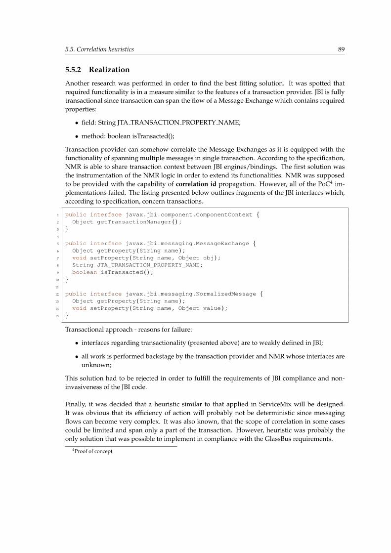
5.5. Correlation heuristics 89
5.5.2 Realization
Another research was performed in order to find the best fitting solution. It was spotted thatrequired functionality is in a measure similar to the features of a transaction provider. JBI is fullytransactional since transaction can span the flow of a Message Exchange which contains requiredproperties:
• field: String JTA TRANSACTION PROPERTY NAME;
• method: boolean isTransacted();
Transaction provider can somehow correlate the Message Exchanges as it is equipped with thefunctionality of spanning multiple messages in single transaction. According to the specification,NMR is able to share transaction context between JBI engines/bindings. The first solution wasthe instrumentation of the NMR logic in order to extend its functionalities. NMR was supposedto be provided with the capability of correlation id propagation. However, all of the PoC4 im-plementations failed. The listing presented below outlines fragments of the JBI interfaces which,according to specification, concern transactions.
1 public interface javax .jbi .component .ComponentContext {2 Object getTransactionManager ( ) ;3 }4
5 public interface javax .jbi .messaging .MessageExchange {6 Object getProperty (String name ) ;7 void setProperty (String name , Object obj ) ;8 String JTA_TRANSACTION_PROPERTY_NAME ;9 boolean isTransacted ( ) ;
10 }11
12 public interface javax .jbi .messaging .NormalizedMessage {13 Object getProperty (String name ) ;14 void setProperty (String name , Object value ) ;15 }
Transactional approach - reasons for failure:
• interfaces regarding transactionality (presented above) are to weakly defined in JBI;
• all work is performed backstage by the transaction provider and NMR whose interfaces areunknown;
This solution had to be rejected in order to fulfill the requirements of JBI compliance and non-invasiveness of the JBI code.
Finally, it was decided that a heuristic similar to that applied in ServiceMix will be designed.It was obvious that its efficiency of action will probably not be deterministic since messagingflows can become very complex. It was also known, that the scope of correlation in some casescould be limited and span only a part of the transaction. However, heuristic was probably theonly solution that was possible to implement in compliance with the GlassBus requirements.
4Proof of concept
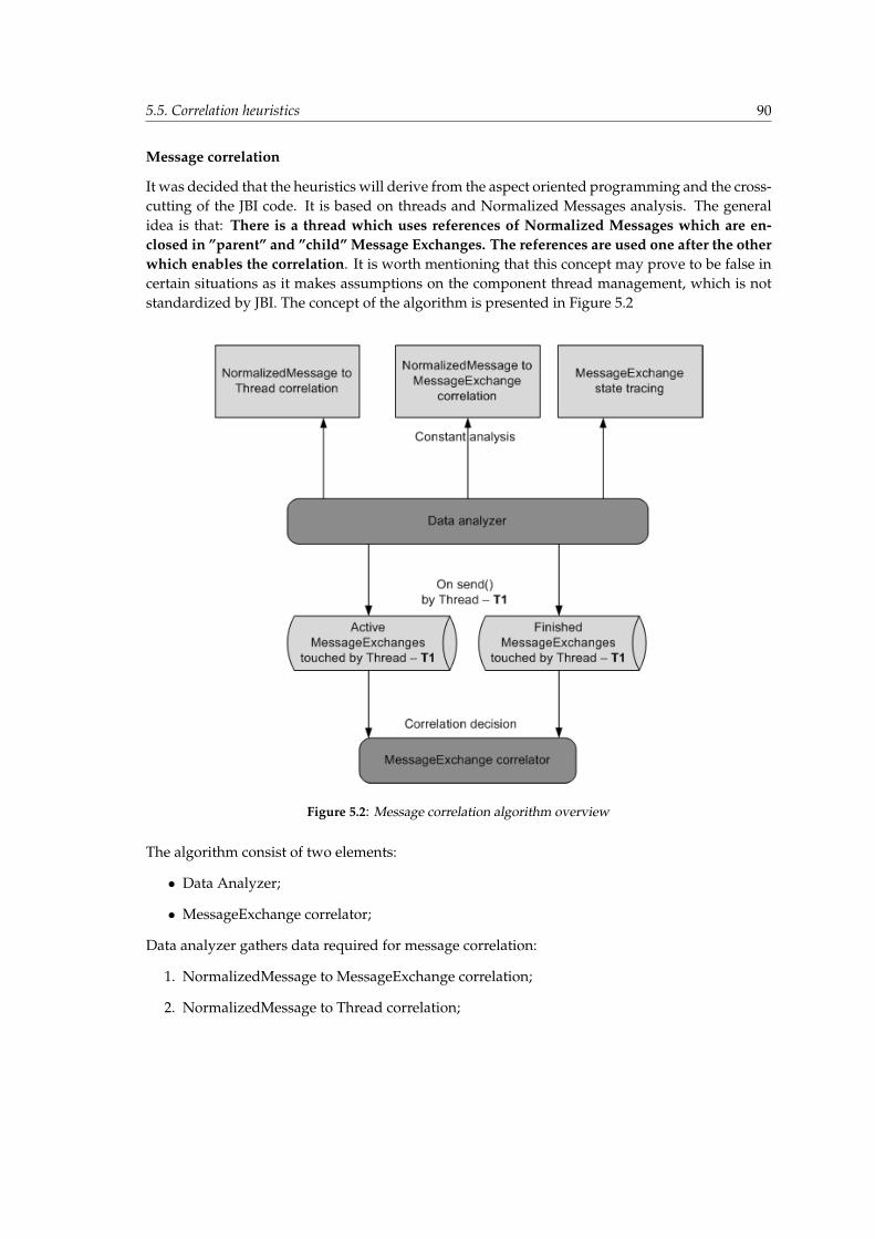
5.5. Correlation heuristics 90
Message correlation
It was decided that the heuristics will derive from the aspect oriented programming and the cross-cutting of the JBI code. It is based on threads and Normalized Messages analysis. The generalidea is that: There is a thread which uses references of Normalized Messages which are en-closed in ”parent” and ”child” Message Exchanges. The references are used one after the otherwhich enables the correlation. It is worth mentioning that this concept may prove to be false incertain situations as it makes assumptions on the component thread management, which is notstandardized by JBI. The concept of the algorithm is presented in Figure 5.2
Figure 5.2: Message correlation algorithm overview
The algorithm consist of two elements:
• Data Analyzer;
• MessageExchange correlator;
Data analyzer gathers data required for message correlation:
1. NormalizedMessage to MessageExchange correlation;
2. NormalizedMessage to Thread correlation;

5.5. Correlation heuristics 91
3. MessageExchange state tracing;
The first operation correlates Normalized Messages with Message Exchanges to which themessages belong. In JBI the relation between these objects has different direction since the Mes-sage Exchanges composite the Normalized Messages. It is done by the pointcut which traces thecreateMessage() operation of the Message Exchange object:
1 pointcut createNormalizedMessage (MessageExchange me ) : call (NormalizedMessagecreateMessage ( ) ) && target (me ) ;
Result: It is possible to get a reference of Message Exchange having only a reference to one of itsNormalized Messages.The second operation traces the usage of Normalized Message objects and marks the threadswhich ”touches” particular Normalized Messages. It is done by the wildcard-pointcut whichtraces all touches of Normalized Messages:
1 pointcut threadMessageMarker (NormalizedMessage nm ) : target (nm ) && call (∗ ∗ ( . . ) )
Result: It is possible to get the references of all NormalizesMessages which were ”touched” byspecified thread.The third operation trace the status of the ongoing Message Exchanges. It is done by a set ofpointcuts which trace the group of send and accept operations defined in DeliveryChannel. Theyare described in Section 5.4.1. Result: It is possible to check the state of Message Exchange (AC-TIVE, DONE, ERROR) having only its reference.
The message correlation is performed always before the first send, sendSync or sendSyncTimeoutoperation of the new Message Exchange. It enables to correlate new Message Exchanges beforethey are sent by NMR. Tracing of send operations is done by three pointcuts:
1 pointcut send (ME , DC ) : execution (void send (ME ) ) ;2 pointcut sendSync (ME , DC ) : execution (boolean sendSync (ME ) ) ;3 pointcut sendSyncTimeout (ME ,long ,DC ) : execution (boolean sendSync (ME , long ) ) ;
The description of the correlation logic reads as follows (overview of the algorithm is presentedin Figure 5.2):
1. Before sending the new Message Exchange ”MX” by thread ”T” get the list of all MessageExchanges touched by thread ”T”.
2. Check the state of all these Message Exchanges and classify them into two groups: A:activeand F:finished.
3. Correlation of ”MX” with other Message Exchange is performed if one of the ”correlation”conditions is fulfilled:
• if (A.size5 == 1) - it deals with the IN-OUT Message Exchange when parent exchangewaits for the results of child exchanges;
5A.size = size of group A;
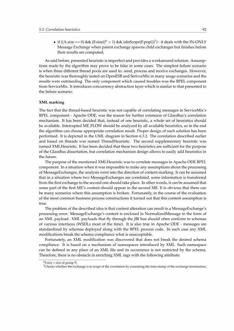
5.5. Correlation heuristics 92
• if ((A.size == 0) && (F.size()6 > 1) && isInScope(F.pop())7) - it deals with the IN-ONLYMessage Exchange when parent exchange spawns child exchanges but finishes beforetheir results are computed;
As said before, presented heuristic is imperfect and provides a workaround solution. Assump-tions made by the algorithm may prove to be false in some cases. The simplest failure scenariois when three different thread pools are used to: send, process and receive exchanges. However,the heuristic was thoroughly tested on OpenESB and SerivceMix in many usage scenarios and theresults were outstanding. The only component which caused troubles was the BPEL componentfrom ServiceMix. It introduces concurrency abstraction layer which is similar to that presented inthe failure scenario.
XML marking
The fact that the thread-based heuristic was not capable of correlating messages in ServiceMix’sBPEL component - Apache ODE, was the reason for further extension of GlassBus’s correlationmechanism. It has been decided that, instead of one heuristic, a whole set of heuristics shouldbe available. Intercepted ME FLOW should be analyzed by all available heuristics, so in the endthe algorithm can choose appropriate correlation result. Proper design of such solution has beenperformed. It is depicted in the UML diagram in Section 6.3.2. The correlation described earlierand based on threads was named ThreadHeuristic. The second supplementary heuristic wasnamed XMLHeuristic. It has been decided that these two heuristics are sufficient for the purposeof the GlassBus dissertation, but correlation mechanism design allows to easily add heuristics inthe future.
The purpose of the mentioned XMLHeuristic was to correlate messages in Apache ODE BPELcomponent. In a situation when it was impossible to make any assumptions about the processingof MessageExchanges, the analysis went into the direction of content marking. It can be assumedthat in a situation where two MessageExchanges are correlated, some information is transferredfrom the first exchange to the second one should take place. In other words, it can be assumed thatsome part of the first ME’s content should appear in the second ME. It is obvious that there canbe many scenarios where this assumption is broken. Fortunately, in the course of the evaluationof the most common business process constructions it turned out that this content assumption istrue.
The problem of the described idea is that content alteration can result in a MessageExchange’sprocessing error. MessageExchange’s content is enclosed in NormalizedMessage in the form ofan XML payload. XML payloads that fly through the JBI bus should often conform to schemasof various interfaces (WSDLs most of the time). It is also true in Apache ODE - messages arestandardized by schemas deployed along with the BPEL process code. In such case any XMLmodifications break the schema compliance what is unacceptable.
Fortunately, an XML modification was discovered that does not break the desired schemacompliance. It is based on a mechanism of namespaces introduced by XML. Such namespacecan be defined in any place of an XML file and its occurrence is not restricted by the schema.Therefore, there is no obstacle in enriching XML tags with the following attribute:
6F.size = size of group F;7Checks whether the exchange is in scope of the correlation by examining the time-stamp of the exchange termination;
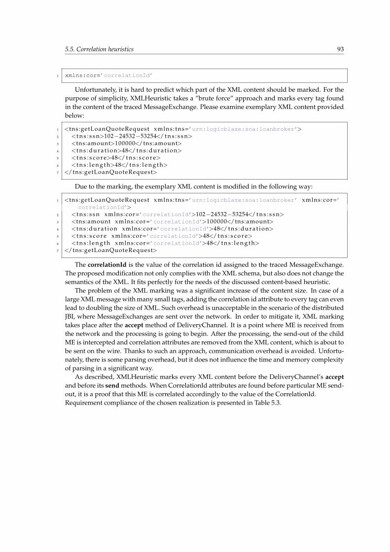
5.5. Correlation heuristics 93
1 xmlns:cor=’correlationId’
Unfortunately, it is hard to predict which part of the XML content should be marked. For thepurpose of simplicity, XMLHeuristic takes a ”brute force” approach and marks every tag foundin the content of the traced MessageExchange. Please examine exemplary XML content providedbelow:
1 <tns:getLoanQuoteRequest xmlns : tns=’urn:logicblaze:soa:loanbroker’>2 <t n s : s s n>102−24532−53254</ t n s : s s n>3 <tns:amount>100000</tns:amount>4 <t n s : d u r a t i o n>48</ t n s : d u r a t i o n>5 <t n s : s c o r e>48</ t n s : s c o r e>6 <t n s : l e n g t h>48</ t n s : l e n g t h>7 </tns:getLoanQuoteRequest>
Due to the marking, the exemplary XML content is modified in the following way:
1 <tns:getLoanQuoteRequest xmlns : tns=’urn:logicblaze:soa:loanbroker’ xmlns:cor=’correlationId’>
2 <t n s : s s n xmlns:cor=’correlationId’>102−24532−53254</ t n s : s s n>3 <tns:amount xmlns:cor=’correlationId’>100000</tns:amount>4 <t n s : d u r a t i o n xmlns:cor=’correlationId’>48</ t n s : d u r a t i o n>5 <t n s : s c o r e xmlns:cor=’correlationId’>48</ t n s : s c o r e>6 <t n s : l e n g t h xmlns:cor=’correlationId’>48</ t n s : l e n g t h>7 </tns:getLoanQuoteRequest>
The correlationId is the value of the correlation id assigned to the traced MessageExchange.The proposed modification not only complies with the XML schema, but also does not change thesemantics of the XML. It fits perfectly for the needs of the discussed content-based heuristic.
The problem of the XML marking was a significant increase of the content size. In case of alarge XML message with many small tags, adding the correlation id attribute to every tag can evenlead to doubling the size of XML. Such overhead is unacceptable in the scenario of the distributedJBI, where MessageExchanges are sent over the network. In order to mitigate it, XML markingtakes place after the accept method of DeliveryChannel. It is a point where ME is received fromthe network and the processing is going to begin. After the processing, the send-out of the childME is intercepted and correlation attributes are removed from the XML content, which is about tobe sent on the wire. Thanks to such an approach, communication overhead is avoided. Unfortu-nately, there is some parsing overhead, but it does not influence the time and memory complexityof parsing in a significant way.
As described, XMLHeuristic marks every XML content before the DeliveryChannel’s acceptand before its send methods. When CorrelationId attributes are found before particular ME send-out, it is a proof that this ME is correlated accordingly to the value of the CorrelationId.Requirement compliance of the chosen realization is presented in Table 5.3.
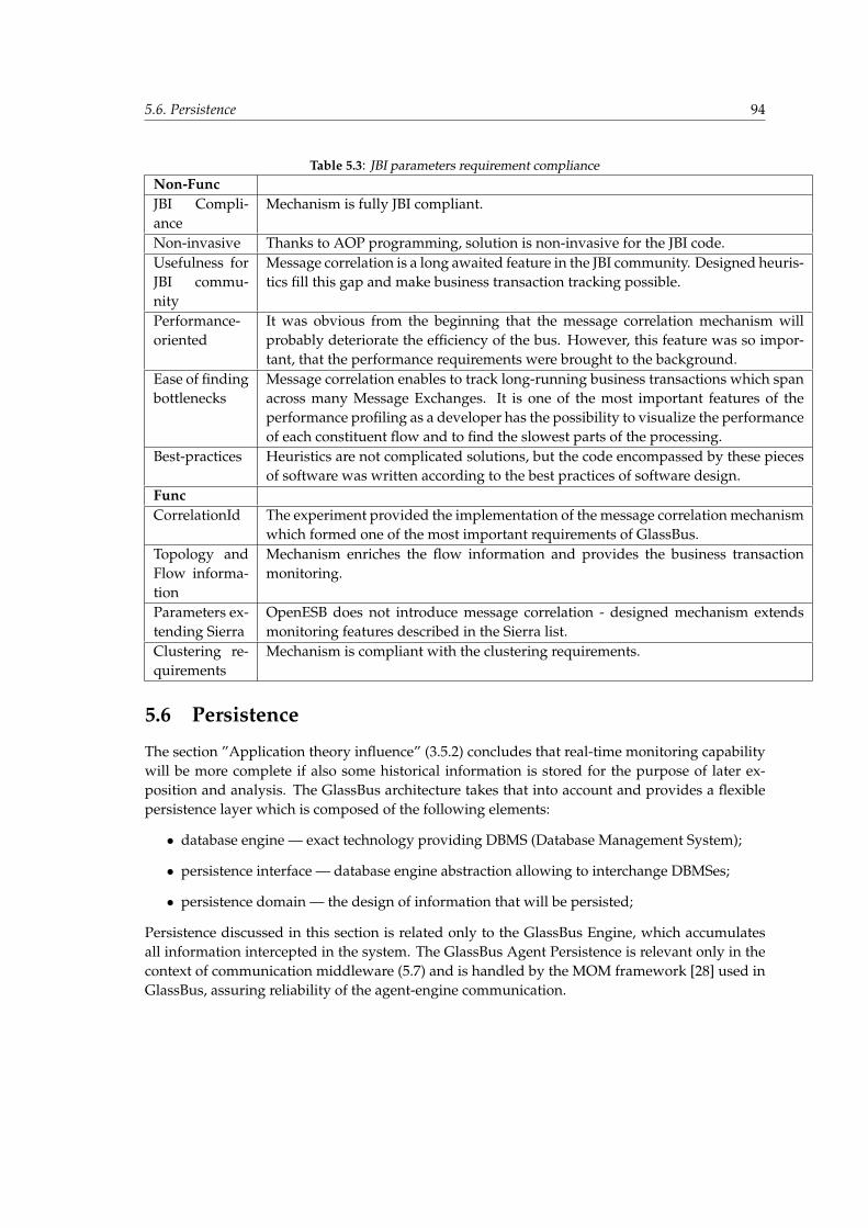
5.6. Persistence 94
Table 5.3: JBI parameters requirement complianceNon-FuncJBI Compli-ance
Mechanism is fully JBI compliant.
Non-invasive Thanks to AOP programming, solution is non-invasive for the JBI code.Usefulness forJBI commu-nity
Message correlation is a long awaited feature in the JBI community. Designed heuris-tics fill this gap and make business transaction tracking possible.
Performance-oriented
It was obvious from the beginning that the message correlation mechanism willprobably deteriorate the efficiency of the bus. However, this feature was so impor-tant, that the performance requirements were brought to the background.
Ease of findingbottlenecks
Message correlation enables to track long-running business transactions which spanacross many Message Exchanges. It is one of the most important features of theperformance profiling as a developer has the possibility to visualize the performanceof each constituent flow and to find the slowest parts of the processing.
Best-practices Heuristics are not complicated solutions, but the code encompassed by these piecesof software was written according to the best practices of software design.
FuncCorrelationId The experiment provided the implementation of the message correlation mechanism
which formed one of the most important requirements of GlassBus.Topology andFlow informa-tion
Mechanism enriches the flow information and provides the business transactionmonitoring.
Parameters ex-tending Sierra
OpenESB does not introduce message correlation - designed mechanism extendsmonitoring features described in the Sierra list.
Clustering re-quirements
Mechanism is compliant with the clustering requirements.
5.6 Persistence
The section ”Application theory influence” (3.5.2) concludes that real-time monitoring capabilitywill be more complete if also some historical information is stored for the purpose of later ex-position and analysis. The GlassBus architecture takes that into account and provides a flexiblepersistence layer which is composed of the following elements:
• database engine — exact technology providing DBMS (Database Management System);
• persistence interface — database engine abstraction allowing to interchange DBMSes;
• persistence domain — the design of information that will be persisted;
Persistence discussed in this section is related only to the GlassBus Engine, which accumulatesall information intercepted in the system. The GlassBus Agent Persistence is relevant only in thecontext of communication middleware (5.7) and is handled by the MOM framework [28] used inGlassBus, assuring reliability of the agent-engine communication.

5.6. Persistence 95
5.6.1 Database choice
The main assumption about DBMS is not to use ”heavy” engines that need separate deploymentprocedure and are accessible externally through TCP - i.e. regular client-server architecture. Ex-amples of such engines: MySQL, DB2, Informix Dynamic Server, Firebird, Microsoft SQL Server,PostgreSQL.
The priority was to use lightweight database solution which would allow to minimize man-agement and assure straightforward procedure of GlassBus Engine deployment (it is describedin Section 5.10). On the other hand, a complex and distributed enterprise bus can generate greatamount of monitoring data which has to be persisted. In such a situation a mature, scalable client-server DBMS would be more appropriate. In order to make such scenario possible, internals ofDBMS have been hidden behind persistence abstraction interface (discussed in the next section),of which the only requirement is a JDBC-compliant database. Database engine layer can be there-fore easily interchanged with any database capable of JDBC. Additionally, DBMS was not themain focus of the GlassBus research, therefore robustness and simplicity of embedded databaseswere more important than wide functionalities of client-server solutions.
The above-mentioned embedded databases, chosen for GlassBus lightweight persistence so-lution, are libraries coupled with the application and accessed through a well-defined interface.In the case of Java technology, the interface is JDBC and the library coupling equip the JVM withall functionalities of DBMS. The following embedded persistence engines have been evaluated:
• Apache Derby8 — mature implementation gaining an increasing popularity (among othersit is used in ServiceMix and ApacheMQ). It has been adopted by SUN as JavaDB and isshipped with newest JDK 6.0. It can be also used in a regular, not-embedded client-servermode. The database library size is about 2 MB.
• H2 9 — It is the first branch of Hypersonic SQL project 10 created by Thomas Mueller, whohas discontinued it in 2001 and started to implement H2 (Hypersonic 2) from scratch. Thedatabase library size is about 1 MB but it contains also the a Console web application, webserver and other tools.
• HSQLDB 11 — It is the second branch of Hypersonic SQL, which, contrary to H2, shares itscodebase. The database library size is about 700 kB.
Derby DB with its 2MB footprint seems to be the heaviest choice. In spite of it being favoredby Apache, many users report performance problems and point to H2 and HSQLDB as less pop-ular but interesting alternatives. Thomas Mueller - the creator of H2 - publishes DB tests [94] thatallow for comparison with various DBMS, not only embedded ones. Part of the test is performedby H2 creator himself and the other part is the result of PolePosition benchmark [38], which isan independent ”benchmark test suite to compare database engines and object-relational map-ping technology”. Both benchmarks show that in most case H2 is a lot more efficient that Derbyand tends towards being slightly faster than HSQLDB. What is also important, H2 outperformedregular DBMSes like PostgreSQL and MySQL.
8http://db.apache.org/derby/9http://www.h2database.com/
10http://hsql.sourceforge.net/11http://hsqldb.org/
5.6. Persistence 96
A similar PolePosition benchmark has been published by the HSQLDB team. Unfortunately,H2 was not among the compared databases, but other (embedded or not) engines have beenclearly outperformed. It is obvious that such tests can lack impartiality, but the introduction of athird-party benchmarking solution - PolePosition - lowers such risk. In addition, Thomas Muellerdefends his performance results in a public discussion with Francois Orsini [39]. Mueller agreesthat some tests can be impartial, but he was not able to find a test in which Derby would clearlyoutperform H2.
Performance test results and feature comparison presented on H2 homepage 12 resulted inchoosing H2 as the GlassBus’s persistence engine. H2 provides a wide variety of persistencestrategies which can be simplified to:
• in-memory persistence;
• file persistence;
In-memory alternative is obviously faster but the lack of data continuity between engine failuresdiscredited it, leaving the option of regular file persistence.
5.6.2 Persistence abstraction
A layer of persistence abstraction was introduced in order to comply with software engineeringgood-practices, which favor decoupling implementation from the interface. The layer providesa regular Java interface. The signatures of the interface methods are defined through domainclasses described later on. The purpose of this layer is to translate this object oriented interfacesto relational internals of underlying DBMS. As it has been mentioned before, the assumption isthat DBMS faces with JDBC, which assures flexibility in changing the engine. It is an analogy tointerchanging the implementation in terms of IT good practices. The goal could be realized inthree different ways:
1. JDBC SQL by-hand — the data in persistence domain is manually stored, retrieved andsearched by means of regular SQL statements executed through a JDBC driver.
2. JDBC BLOBs — the persistence domain is defined by classes of which instances are serial-ized and written to DB as BLOBs [102].
3. ORM framework — a third-party framework is used to map objects into relations in a stan-dardized way.
The second solution has a significant shortcoming - the data cannot be queried on the basisof the content. In case of a query, every record has to be read and deserialized. The specificityof the GlassBus domain makes it unacceptable. The first solution’s implementation complexitydepends on the complexity of the domain, which is not trivial. Additionally, any change in do-main would trigger a modification in the code executing SQL. The SQL dialect of each databaseslightly differs, which makes the compliance with any JDBC-capable database more difficult. Itcould be mitigated by means of the Spring’s Framework13 JDBC support, which facilitates trans-action handling and exception processing, but still it comes to reinventing the wheel — building
12http://www.h2database.com/html/features.html13http://www.springframework.org/
5.6. Persistence 97
Object-Relational Mapping — and that conflicts with the requirement of avoiding NIH. Therefore,it was decided to use an existing ORM solution.
Object-Relational Mapping
There are many ORM frameworks available today, which makes the choice difficult. Some of themost popular:
• Hibernate;
• Oracle’s Toplink;
• JDO - Java Data Objects;
All frameworks started with keeping the object-relational mapping configuration definition inan XML file. Obviously, mapping’s XML schema was different from one framework to another,but it was not a problem because, along with the framework interchange, the mapping could besuperseded. At the same time, the evaluation of EJB-2.1 in production environments revealed anenormous complexity of XML configuration in EJB-2.1 systems maintenance, described as ”XMLhell”.
Java 5.0 introduction leveraged the potential of annotations allowing to bring ORM frame-work to a higher quality level. Each framework provided its own definition of annotations setused to annotate simple POJOs14 and by means of that, configuring the object-relational map-ping. It was the main reason for the ORM inter-framework non-compliance - POJOs annotatedfor one framework did not compile for others. At this tame JSR-220 Expert Group [40] worked onthe EJB-3 specification, which was expected to simplify EJB-2.1, also in terms of persistence. SunJPA FAQ comments it in the following way: ”(...) simplification of EJB CMP was not enough, andthat what was needed was a POJO persistence framework in line with other O/R mapping tech-nologies available in the industry”. This POJO persistence framework was called Java PersistenceAPI (JPA) and introduced a new standard of ORM frameworks. Its flexibility made it usable notonly in EJB scope, but also for the purpose of regular J2SE applications.
Java Persistence API
JPA Advantages:
• The entire Java community can use a single, standard persistence API.
• It draws upon the best ideas from persistence technologies (Toplink, Hibernate, JDO). It wasdecided that combining several persistence technologies would be better than making oneof the ORM frameworks (e.g. Hibernate) a standard.
• The end of incompatible non-standard persistence models for object/relational mappings.
• It supports a rich, SQL-like query language.
• It supports the use of pluggable persistence providers.
14Plain old java objects
5.6. Persistence 98
Java Persistence effort triggered adoption of existing ORM solutions to the standardized JPA. Itwas not difficult because JPA was founded on those ORM frameworks. Right now, there are manycommercial and open source JPA implementations available: CocoBase, DataNucleus, GlassFish,TopLink, EclipseLink, Hibernate, OpenJPA, Cayenne.
It has been decided that JPA fits perfectly into the GlassBus persistence needs providing asimple and well-standardized solution. Most popular and mature JPA implementations are Hi-bernate and Toplink. Their quality is similar, but Toplink’s Essentials (open-source communityedition of Oracle’s TopLink product) was classified as reference implementation the use of whichwill force full specification compliance allowing to avoid problems during future interchange ofpersistence providers.
Spring enhancement
The motivation for Spring Framework 15 was high J2EE complexity and belief that its develop-ment should be less difficult. Spring encompasses many functionally-varied modules which aiddevelopment of enterprise application by providing a framework for convenient realization ofwell-known enterprise good practices. The aim of spring is not to supersede J2EE (however somemechanisms can be used interchangeably with J2EE), but to enhance it.
The support for Java Persistence API was introduced in Spring 2.0, allowing to leverage itsORM enhancements [41]:
• Ease of testing - ability to swap the implementations and the locations of the configurationfiles.
• Common data access exceptions - conversion from a proprietary to common DataAccessEx-ception hierarchy.
• General resource management - spring application contexts.
• Integrated transaction management - wrap mapping code with interceptor managing trans-actions.
Spring-JPA causes dramatic increase of unit testing ease. JUnit extends AbstractJpaTests classfrom Spring, which allows to perform each test in a separate transaction that is roll-backed atthe end. It provides the advantage of not changing the state of the database, which could betroublesome.Spring JPA enhancement has been evaluated in two ways:
1. with JpaTemplate - it integrates more tightly with Spring and therefore allows to instantlybenefit from its mentioned ORM enhancements; exceptions are: translation and automatictransactions handling by means of the transactional EntityManager.
2. without JpaTemplate - leaving the developer with more freedom of choosing particular fea-tures. Transactions and exceptions support can be enabled (by means of XML configurationor annotations) or they can be handled in another specific way.
15http://www.springframework.org/
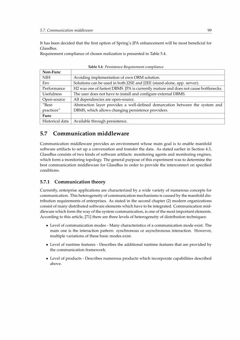
5.7. Communication middleware 99
It has been decided that the first option of Spring’s JPA enhancement will be most beneficial forGlassBus.Requirement compliance of chosen realization is presented in Table 5.4.
Table 5.4: Persistence Requirement complianceNon-FuncNIH Avoiding implementation of own ORM solution.Env Solutions can be used in both J2SE and J2EE (stand-alone, app. server).Performance H2 was one of fastest DBMS. JPA is currently mature and does not cause bottlenecks.Usefulness The user does not have to install and configure external DBMS.Open-source All dependencies are open-source.”Best-practices”
Abstraction layer provides a well-defined demarcation between the system andDBMS, which allows changing persistence providers.
FuncHistorical data Available through persistence.
5.7 Communication middleware
Communication middleware provides an environment whose main goal is to enable manifoldsoftware artifacts to set up a conversation and transfer the data. As stated earlier in Section 4.3,GlassBus consists of two kinds of software artifacts: monitoring agents and monitoring engines,which form a monitoring topology. The general purpose of this experiment was to determine thebest communication middleware for GlassBus in order to provide the interconnect on specifiedconditions.
5.7.1 Communication theory
Currently, enterprise applications are characterized by a wide variety of numerous concepts forcommunication. This heterogeneity of communication mechanisms is caused by the manifold dis-tribution requirements of enterprises. As stated in the second chapter (2) modern organizationsconsist of many distributed software elements which have to be integrated. Communication mid-dleware which form the way of the system communication, is one of the most important elements.According to this article, [71] there are three levels of heterogeneity of distribution techniques:
• Level of communication modes - Many characteristics of a communication mode exist. Themain one is the interaction pattern: synchronous or asynchronous interaction. However,multiple variations of these basic modes exist.
• Level of runtime features - Describes the additional runtime features that are provided bythe communication framework.
• Level of products - Describes numerous products which incorporate capabilities describedabove.
5.7. Communication middleware 100
Characteristics of communication middleware
Wide variety of characteristics of the communication middleware exists. These are important asthey describe the main capabilities and emphasize the vital differences between solutions. Thenext subsection presents the main attributes that should be taken under consideration during theapplication design. Capabilities can be classified into the aforementioned levels: communicationmodes or runtime features.
Synchronous versus Asynchronous Interaction - Synchronous communication is characterizedby the strict request/reply communication pattern which it implements. Request is fol-lowed by the immediate response which is awaited by the requester during a blocking call.It is required that both sides of communication (requester and provider) are available andfully functional, at the same point of time, to perform the successive conversation. Asyn-chronous communication is characterized by the fact that the requester and provider aredecoupled. Typically, requester sends a request but no immediate response is awaited. Thesender can retrieve the result at any point of time, after the provider returns the result. It ispossible thanks to the intermediary that administers the communication. It is NOT requiredthat both sides of the communication (requester and provider) are available and fully func-tional, at the same point of time, to perform the successive conversation.
Interface versus Payload Semantics - In general, communication is based on a bidirectional con-versation in which both sides send and retrieve pieces of information. Typically, the re-quester invokes a transaction or operation the results of which are sent back to the clientby the provider. The encapsulation of the invocation logic is normally performed in one oftwo ways. The first way is based on ”interface semantics”. The requested transaction setis defined as a type of semantically rich interface which consists of procedures that havemeaningful names which describe their purpose. Interface semantics provide the program-mer with an intuitive interface which is easy to understand and use. The second way isbased on payload semantics. In this case the invocation logic is encompassed in a messagepayload and sent to the provider which is determined only by its address. The providerhas to recognize the payload and invoke associated business function. Payload semanticsis usually used in a message oriented middleware (described later) which provides a set ofget/put or send/receive functions.
Tight versus Loose Coupling - tight and loose coupling are widely discussed in the IT world.There is no certain definition what it actually means. Coupling, which referes to joiningthings together can be discussed on different levels. The table, created by [71], entirelycovers this issue.
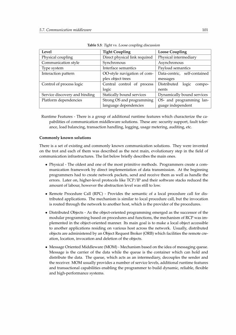
5.7. Communication middleware 101
Table 5.5: Tight vs. Loose coupling discussion
Level Tight Coupling Loose CouplingPhysical coupling Direct physical link required Physical intermediaryCommunication style Synchronous AsynchronousType system Interface semantics Payload semanticsInteraction pattern OO-style navigation of com-
plex object treesData-centric, self-containedmessages
Control of process logic Central control of processlogic
Distributed logic compo-nents
Service discovery and binding Statically bound services Dynamically bound servicesPlatform dependencies Strong OS and programming
language dependenciesOS- and programming lan-guage independent
Runtime Features - There is a group of additional runtime features which characterize the ca-pabilities of communication middleware solutions. These are: security support, fault toler-ance, load balancing, transaction handling, logging, usage metering, auditing, etc.
Commonly known solutions
There is a set of existing and commonly known communication solutions. They were inventedon the trot and each of them was described as the next main, evolutionary step in the field ofcommunication infrastructures. The list below briefly describes the main ones.
• Physical - The oldest and one of the most primitive methods. Programmers create a com-munication framework by direct implementation of data transmission. At the beginningprogrammers had to create network packets, send and receive them as well as handle theerrors. Later on, higher-level protocols like TCP/IP and their software stacks reduced theamount of labour, however the abstraction level was still to low.
• Remote Procedure Call (RPC) - Provides the semantic of a local procedure call for dis-tributed applications. The mechanism is similar to local procedure call, but the invocationis routed through the network to another host, which is the provider of the procedures.
• Distributed Objects - As the object-oriented programming emerged as the successor of themodular programming based on procedures and functions, the mechanism of RCP was im-plemented in the object-oriented manner. Its main goal is to make a local object accessibleto another applications residing on various host across the network. Usually, distributedobjects are administered by an Object Request Broker (ORB) which facilities the remote cre-ation, location, invocation and deletion of the objects.
• Message Oriented Middleware (MOM) - Mechanism based on the idea of messaging queue.Message is the carrier of the data while the queue is the container which can hold anddistribute the data. The queue, which acts as an intermediary, decouples the sender andthe receiver. MOM usually provides a number of service levels, additional runtime featuresand transactional capabilities enabling the programmer to build dynamic, reliable, flexibleand high-performance systems.
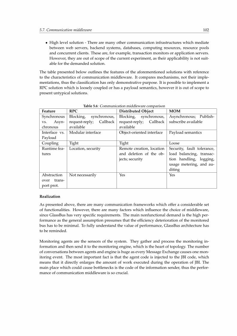
5.7. Communication middleware 102
• High level solution - There are many other communication infrastructures which mediatebetween web servers, backend systems, databases, computing resources, resource poolsand concurrent clients. These are, for example, transaction monitors or application servers.However, they are out of scope of the current experiment, as their applicability is not suit-able for the demanded solution.
The table presented below outlines the features of the aforementioned solutions with referenceto the characteristics of communication middleware. It compares mechanisms, not their imple-mentations, thus the classification has only demonstrative purpose. It is possible to implement aRPC solution which is loosely coupled or has a payload semantics, however it is out of scope topresent untypical solutions.
Table 5.6: Communication middleware comparisonFeature RPC Distributed Object MOMSynchronousvs. Asyn-chronous
Blocking, synchronous,request-reply; Callbackavailable
Blocking, synchronous,request-reply; Callbackavailable
Asynchronous; Publish-subscribe available
Interface vs.Payload
Modular interface Object-oriented interface Payload semantics
Coupling Tight Tight LooseRuntime fea-tures
Location, security Remote creation, locationand deletion of the ob-jects; security
Security, fault tolerance,load balancing, transac-tion handling, logging,usage metering, and au-diting
Abstractionover trans-port prot.
Not necessarily Yes Yes
Realization
As presented above, there are many communication frameworks which offer a considerable setof functionalities. However, there are many factors which influence the choice of middleware,since GlassBus has very specific requirements. The main nonfunctional demand is the high per-formance as the general assumption presumes that the efficiency deterioration of the monitoredbus has to be minimal. To fully understand the value of performance, GlassBus architecture hasto be reminded.
Monitoring agents are the sensors of the system. They gather and process the monitoring in-formation and then send it to the monitoring engine, which is the heart of topology. The numberof conversations between agents and engine is huge as every Message Exchange causes one mon-itoring event. The most important fact is that the agent code is injected to the JBI code, whichmeans that it directly enlarges the amount of work executed during the operation of JBI. Themain place which could cause bottlenecks is the code of the information sender, thus the perfor-mance of communication middleware is so crucial.
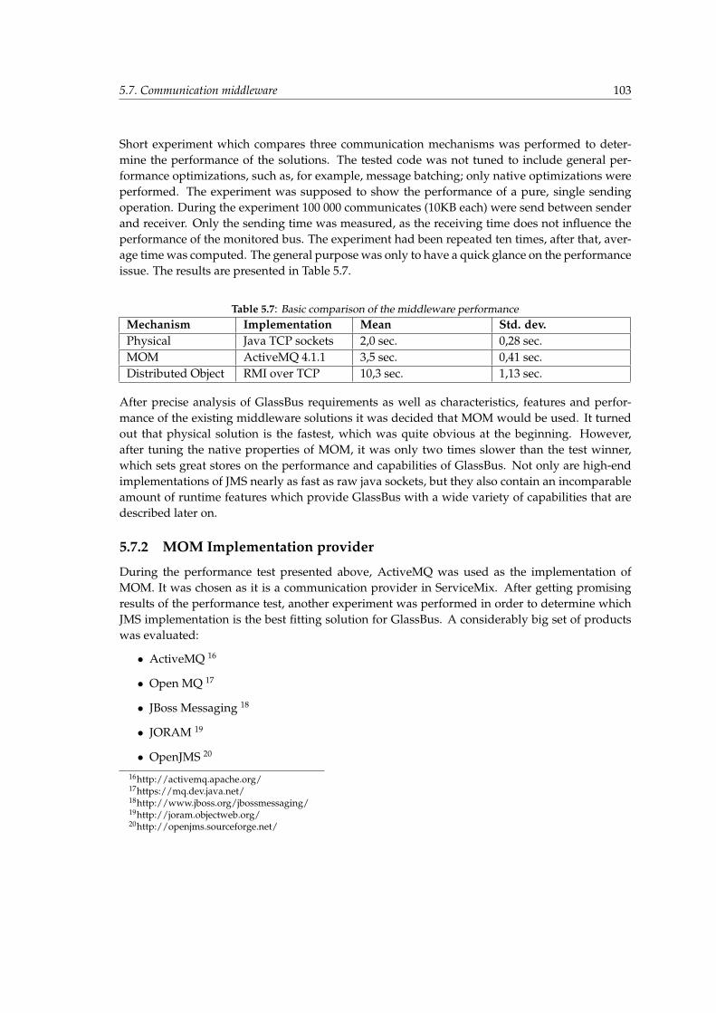
5.7. Communication middleware 103
Short experiment which compares three communication mechanisms was performed to deter-mine the performance of the solutions. The tested code was not tuned to include general per-formance optimizations, such as, for example, message batching; only native optimizations wereperformed. The experiment was supposed to show the performance of a pure, single sendingoperation. During the experiment 100 000 communicates (10KB each) were send between senderand receiver. Only the sending time was measured, as the receiving time does not influence theperformance of the monitored bus. The experiment had been repeated ten times, after that, aver-age time was computed. The general purpose was only to have a quick glance on the performanceissue. The results are presented in Table 5.7.
Table 5.7: Basic comparison of the middleware performanceMechanism Implementation Mean Std. dev.Physical Java TCP sockets 2,0 sec. 0,28 sec.MOM ActiveMQ 4.1.1 3,5 sec. 0,41 sec.Distributed Object RMI over TCP 10,3 sec. 1,13 sec.
After precise analysis of GlassBus requirements as well as characteristics, features and perfor-mance of the existing middleware solutions it was decided that MOM would be used. It turnedout that physical solution is the fastest, which was quite obvious at the beginning. However,after tuning the native properties of MOM, it was only two times slower than the test winner,which sets great stores on the performance and capabilities of GlassBus. Not only are high-endimplementations of JMS nearly as fast as raw java sockets, but they also contain an incomparableamount of runtime features which provide GlassBus with a wide variety of capabilities that aredescribed later on.
5.7.2 MOM Implementation provider
During the performance test presented above, ActiveMQ was used as the implementation ofMOM. It was chosen as it is a communication provider in ServiceMix. After getting promisingresults of the performance test, another experiment was performed in order to determine whichJMS implementation is the best fitting solution for GlassBus. A considerably big set of productswas evaluated:
• ActiveMQ 16
• Open MQ 17
• JBoss Messaging 18
• JORAM 19
• OpenJMS 20
16http://activemq.apache.org/17https://mq.dev.java.net/18http://www.jboss.org/jbossmessaging/19http://joram.objectweb.org/20http://openjms.sourceforge.net/
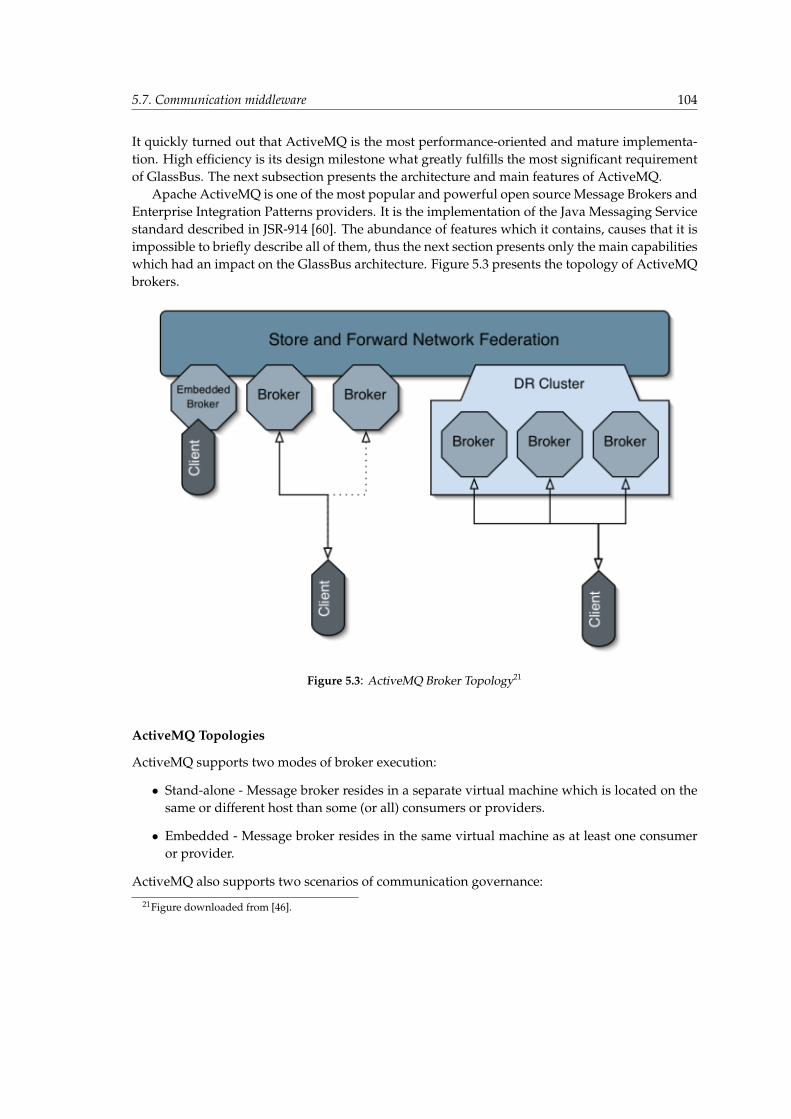
5.7. Communication middleware 104
It quickly turned out that ActiveMQ is the most performance-oriented and mature implementa-tion. High efficiency is its design milestone what greatly fulfills the most significant requirementof GlassBus. The next subsection presents the architecture and main features of ActiveMQ.
Apache ActiveMQ is one of the most popular and powerful open source Message Brokers andEnterprise Integration Patterns providers. It is the implementation of the Java Messaging Servicestandard described in JSR-914 [60]. The abundance of features which it contains, causes that it isimpossible to briefly describe all of them, thus the next section presents only the main capabilitieswhich had an impact on the GlassBus architecture. Figure 5.3 presents the topology of ActiveMQbrokers.
Figure 5.3: ActiveMQ Broker Topology21
ActiveMQ Topologies
ActiveMQ supports two modes of broker execution:
• Stand-alone - Message broker resides in a separate virtual machine which is located on thesame or different host than some (or all) consumers or providers.
• Embedded - Message broker resides in the same virtual machine as at least one consumeror provider.
ActiveMQ also supports two scenarios of communication governance:
21Figure downloaded from [46].
5.7. Communication middleware 105
• One broker, many clients - The typical scenario of JMS communication. Only one broker(stand-alone or embedded) exists and acts as a intermediary among clients which produceand consume messages. This is implementation of the hub and spoke architecture based onclient/server mechanism.
• Many brokers, many clients (Store and forward network federation) - High-end, sophisti-cated JMS communication scenario which provides massive scalability of a large messagingfabric. It extends the hub and spoke architecture in which sole broker is the single point offailure. In this scenario brokers are connected together and form a network (or cluster) ofbrokers so that the system could survive failure of any particular broker, machine or subnet.Clients are allowed to connect to any broker in the network and fail over to another brokerin case of failure. Network of Brokers provides store and forward mechanism to distributemessages from brokers with producers to brokers with consumers, which allows to supportdistributed queues and topics across a network of brokers. Normally, the connection be-tween brokers is one-way. In order to create bidirectional conversation two connection haveto be opened. As it generated synchronization troubles in some usage scenarios, from ver-sion 5.x of ActiveMQ, a network connection can be optionally enabled to be duplex. Autodiscovery of brokers is supported, so clients can automatically detect and connect to a bro-ker out of a logical group of brokers as well as brokers can discover and connect to otherbrokers to form large networks. Auto discovery is based on a hard-coded list of availablebrokers or on a multicast discovery protocol.
ActiveMQ Clustering
Clustering is a large concept and can span across many aspects of resource redundancy. Networkof brokers mechanism, which is described above, can be discussed with reference to clustering, asit provides redundancy of the next-hop broker for producers and consumers. In case of a failureclients can fail over to another broker on the network to preserve the ongoing conversation. How-ever, mechanism whose main goal is to distribute messages to clients connected to distributedbrokers, has its limitations. It is not hard to imagine a situation in which operating broker gathersmessages in queue for which, at the specified point of time, no consumers exist. The messagesare stored, but not forwarded, since no consumer exists. If the very broker fails, the messages areunavailable. In addition, if the broker does not persist messages, they are lost forever.Therefore, ActiveMQ introduces two mechanisms which cope with this problem and form a dis-aster recovery (DR) solution.
• Pure Master Slave - This mechanism provides messages replication to a slave broker, soeven in case of hardware failure of the master’s machine, no messages are lost, as the slavebroker takes over, making stored messages available with imperceptible delay. This is ashared-nothing, fully replicated topology with independent brokers.
• Replicated Message Stores - An alternative mechanism to master slave which contains slightdifferences. Two brokers (master and slave) are not fully independent, as they share a com-mon message store, for example SAN. In case of a master’s broker failure slave broker con-nects to the shared store of messages and takes over ongoing conversations. Recommendedfor brokers which have access to highly-available stores, such as RAID drives or SANs.
5.7. Communication middleware 106
ActiveMQ Transports
ActiveMQ provides a set of transport protocols which enables the clients to connect to brokers orthe brokers to connect to each other.
• The VM Transport - One of the most interesting transport ways. Allows clients to connect tothe embedded broker which exists in the same virtual machine. The connection uses directmethod invocation to omit the overhead of the network communication.
• The TCP Transport - Allows clients to connect to the remote broker using a TCP socket.
• The UDP Transport - Allows clients to connect to the remote broker using a UDP socket.
• The NIO Transport - Similar to TCP transport, however new version of Java IO (NIO) isused.
• The SSL Transport - Allows clients to connect to the remote broker using a secure, SSL-encrypted, TCP communication.
• The Peer Transport - Provides a peer to peer network. Every client contains embedded,local broker and uses the VM transport to communicate with it. Broker establishes networkconnections to other embedded brokers residing on different clients, forming a peer to peer,JMS network.
• The Multicast Transport - Allows clients to connect to the remote broker using multicast.
• The HTTP and HTTPS Transport - Allows clients to connect to the remote broker usingHTTP/HTTPS tunneling which helps to avoid problems with connectivity due to corporatefirewalls.
ActiveMQ Persistence
ActiveMQ supports numerous persistence configurations.
• No persistence;
• JDBC Persistence without journaling;
• JDBC persistence with high performance journal;
• AMQ Message Store (with Kaha persistence);
The most important option is the AMQ Message Store which is the default storage for ActiveMQversion five and above. Accorging to the authors [45], this embeddable and transactional messagestorage is extremly fast, reliable and easily recoverable.Description, taken from the ActiveMQ site [45] describes the store in details: ”Messages them-selves are persisted in the data logs of the journal - with references to their location being heldby a reference store (by default Kaha) for fast retrieval. References to messages are held in mem-ory, and periodically inserted into the reference store to improve performance. The messages arestored in data logs, which are individual files, typically 32mb in size (though this is configurable,they can be larger if the size of a message is large than the file size). When all the messages in adata log have been successfully consumed, the data log file is marked as being ready to be deleted- or archived - which will happen at the next clean up period.”

5.7. Communication middleware 107
ActiveMQ Performance
The performance of ActiveMQ was meticulously evaluated in order to find the best configuration.Results of the performance experiments are presented below in Table 5.8 and 5.9.
Table 5.8: ActiveMQ performance comparison - embedded brokersSender ReceiverEmbedded broker; VM transport; Persistencedisabled;
Embedded broker; VM transport; Persistencedisabled;
Receiver was started after the sender had finished.Mean: 1,73 sec; Mean: 13,04 sec;Std.dev.: 0,34 sec; Std.dev.: 1,17 sec;
Embedded broker; VM transport; EmbeddedKaha Persistence;
Embedded broker; VM transport; EmbeddedKaha Persistence;
Receiver was started after the sender had finished.Mean:5,48 sec; Mean:22,29 sec;Std.dev.: 0,63 sec; Std.dev.: 2,37 sec;
Embedded broker; VM transport; Persistencedisabled;
Embedded broker; VM transport; Persistencedisabled;
Receiver was running simultaneously with sender.Mean: 5,02 sec; Mean: 10,12 sec;Std.dev.: 0,78 sec; Std.dev.: 1,37 sec;
Embedded broker; VM transport; EmbeddedKaha Persistence;
Embedded broker; VM transport; EmbeddedKaha Persistence;
Receiver was running simultaneously with sender.Mean:16,9 sec; Mean:23,5 sec;Std.dev.: 1,81 sec; Std.dev.: 3,54 sec;
During the experiment, which was similar to the one presented in Section 5.6, 100 000 commu-nicates, whose size was ten kilobytes, were sent between sender and receiver. Transmission timewas measured on the sender and receiver side. Transmission time was averaged to the executiontime of sender and receiver since the overhead of other operations performed by these partiesdoes not have a negligible effect on the results. The experiment had been repeated ten times, afterthat, average time was computed.Table 5.8 shows the impact of persistence and communication parallelism on the performance ofthe sender and receiver. The fastest option is the solution with disabled persistence when oper-ations of sending and receiving are performed one after another. However, it is hard to assumethat in the JBI environment the communication between parties will not be simultaneous.
The table 5.9 shows the performance comparison of the persistence mechanisms. Kaha per-sistence is the fastest option. But, what is worth mentioning, it deteriorates the efficiency of thesender almost two-fold. While comparing the results of tests presented in Table 5.8 and 5.9, itis easily observable that sender is ten-fold slower when it uses remote broker than when localbroker is used at the server side (1,73 sec. versus 13,13 sec.).
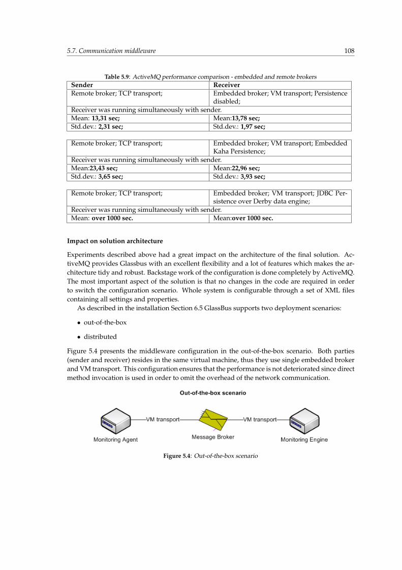
5.7. Communication middleware 108
Table 5.9: ActiveMQ performance comparison - embedded and remote brokersSender ReceiverRemote broker; TCP transport; Embedded broker; VM transport; Persistence
disabled;Receiver was running simultaneously with sender.Mean: 13,31 sec; Mean:13,78 sec;Std.dev.: 2,31 sec; Std.dev.: 1,97 sec;
Remote broker; TCP transport; Embedded broker; VM transport; EmbeddedKaha Persistence;
Receiver was running simultaneously with sender.Mean:23,43 sec; Mean:22,96 sec;Std.dev.: 3,65 sec; Std.dev.: 3,93 sec;
Remote broker; TCP transport; Embedded broker; VM transport; JDBC Per-sistence over Derby data engine;
Receiver was running simultaneously with sender.Mean: over 1000 sec. Mean:over 1000 sec.
Impact on solution architecture
Experiments described above had a great impact on the architecture of the final solution. Ac-tiveMQ provides Glassbus with an excellent flexibility and a lot of features which makes the ar-chitecture tidy and robust. Backstage work of the configuration is done completely by ActiveMQ.The most important aspect of the solution is that no changes in the code are required in orderto switch the configuration scenario. Whole system is configurable through a set of XML filescontaining all settings and properties.
As described in the installation Section 6.5 GlassBus supports two deployment scenarios:
• out-of-the-box
• distributed
Figure 5.4 presents the middleware configuration in the out-of-the-box scenario. Both parties(sender and receiver) resides in the same virtual machine, thus they use single embedded brokerand VM transport. This configuration ensures that the performance is not deteriorated since directmethod invocation is used in order to omit the overhead of the network communication.
Figure 5.4: Out-of-the-box scenario
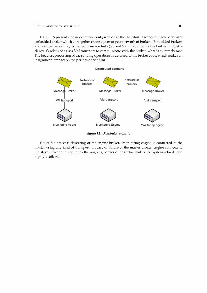
5.7. Communication middleware 109
Figure 5.5 presents the middleware configuration in the distributed scenario. Each party usesembedded broker which all together create a peer to peer network of brokers. Embedded brokersare used, as, according to the performance tests (5.8 and 5.9), they provide the best sending effi-ciency. Sender code uses VM transport to communicate with the broker, what is extremely fast.The heaviest processing of the sending operations is deferred to the broker code, which makes aninsignificant impact on the performance of JBI.
Figure 5.5: Distributed scenario
Figure 5.6 presents clustering of the engine broker. Monitoring engine is connected to themaster using any kind of transport. In case of failure of the master broker, engine connects tothe slave broker and continues the ongoing conversations what makes the system reliable andhighly-available.
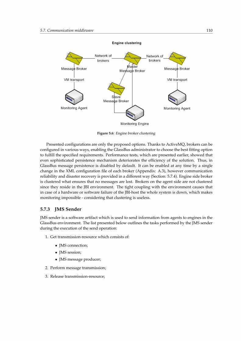
5.7. Communication middleware 110
Figure 5.6: Engine broker clustering
Presented configurations are only the proposed options. Thanks to ActiveMQ, brokers can beconfigured in various ways, enabling the GlassBus administrator to choose the best fitting optionto fulfill the specified requirements. Performance tests, which are presented earlier, showed thateven sophisticated persistence mechanism deteriorates the efficiency of the solution. Thus, inGlassBus message persistence is disabled by default. It can be enabled at any time by a singlechange in the XML configuration file of each broker (Appendix: A.3), however communicationreliability and disaster recovery is provided in a different way (Section: 5.7.4). Engine side brokeris clustered what ensures that no messages are lost. Brokers on the agent side are not clusteredsince they reside in the JBI environment. The tight coupling with the environment causes thatin case of a hardware or software failure of the JBI-host the whole system is down, which makesmonitoring impossible - considering that clustering is useless.
5.7.3 JMS Sender
JMS sender is a software artifact which is used to send information from agents to engines in theGlassBus environment. The list presented below outlines the tasks performed by the JMS senderduring the execution of the send operation:
1. Get transmission-resource which consists of:
• JMS connection;
• JMS session;
• JMS message producer;
2. Perform message transmission;
3. Release transmission-resource;
5.7. Communication middleware 111
Two problems concerning the usage of the JMS sender had to be solved in order to design a robustand efficient solution. The first one regards thread safety. GlassBus agent consist of aspects whichare injected to the code of JBI, which causes that the JMS sender is used simultaneously in manythreads aggregated by the thread pools of the bus. The second one regards resource acquisitionsince the process of creating and releasing the transmission-resource from scratch (initiating theconnection, negotiating the parameters, creating session, creating message producer, closing allresources, etc.) is very complex, heavy and inefficient.
According to the best practices of software design there are at least two solutions which coverthe presented issue:
1. Send and receive operations of the JMS sender are synchronized; JMS sender acquires singletransmission resource at the creation time and uses it during the whole life-cycle.
2. Send and receive operations of the JMS sender are NOT synchronized; JMS sender usestransmission resource pool which copes with the thread-safe resource management;
In order to choose the most efficient solution some performance tests were conducted. Theresults are presented in Table 5.10. Tests consisted of two experiments which investigated theperformance of proposed solutions on a multi-core machine. They were repeated ten times - thenthe average time was computed.
• Experiment number one - One and only one sending thread. Thread performs 100 000 sendoperations. Message contains ten kilobytes of data. Duration of the whole sending processmeasured.
• Experiment number two - 100 simultaneous sending threads and 10 pooled transmissionresources; Thread performs 100 000 send operations (all together). Message contains tenkilobytes of data. Duration of the whole sending process measured (sum of the duration ofthe sending process in each thread).
Table 5.10: JMS sender performance comparisonExperiment Solution number one Solution number twoOne Mean: 3,77 sec. Std.dev.: 0,42 sec. Mean: 4,1 sec. Std.dev.: 0,31 sec.Two Mean: 3,95 sec. Std.dev.: 0,35 sec. Mean: 1,1 sec. Std.dev.: 0,12 sec.
Experiment one, which tested the sequential (one-threaded) JMS sender, shows that the sec-ond solution is slightly slower. This is quite obvious since minimal overhead due to resourcepool management exists. Experiment number two shows what is good under the hood of thesecond solution. It greatly improves the performance in the multi-threaded environment as theoperations are executed simultaneously and do not have to share single transmission-resource,which greatly improves the throughput of the communication backbone. The efficiency is almostfour-fold better. After evaluation of the performance tests solution number two was chosen.
At the beginning JMSTemplate 22 provided the implementation of the JMS sender. However,later on due to performance bottlenecks, which were caused by redundant computation logic en-compassed by this solution, proprietary implementation 23 was proposed. It is characterized by
22org.springframework.jms.core.JmsTemplate - Spring Framework 2.023pl.edu.agh.glassbus.agent.sender.JmsSender A.2
5.7. Communication middleware 112
the fact that it is the simplest possible way of implementing the JMS sender. Auxiliary perfor-mance test which are off the record showed that the performance is between two and three timesbetter. Usage of transmission resource pool is transparent for the JMS sender as all the backstagework is performed by the connection factory. JcaPooledConnectionFactory 24 from Java Con-nector Architecture (JCA) 25 container provides the high-performance implementation of threadpooling, resource pooling, transaction handling and consumption of resource adapters [63].
Summary of all features contained by the JMS sender implemented in glassbus:
• Sending mechanism - proprietary implementation of JMS sending logic. Send and receiveoperations of the sender are NOT synchronized; JMS uses transmission resource pool whichcopes with the thread-safe resource management;
• Transmission reliability - local JMS transactions (described in Section 5.7.4).
• Resource management - JMS transmission resource pools provided by JCA container.
• Broker failure protection - not provided, in case of host failure the whole monitoring systemis down.
5.7.4 JMS Receiver
JMS receiver is a software artifact which is used to receive information sent by agents in theGlassBus environment. The list presented below outlines the tasks performed by the JMS receiverduring the execution of the receive operation:
1. Get transmission-resource which consist of:
• JMS connection;
• JMS session;
• JMS message producer;
2. Perform receipt of message;
3. Store message in a data-store;
4. Release transmission-resource;
In order to provide implementation of the receipt mechanism which is fully compliant with thebest practices of the software design, a short research was performed. It quickly occurred thatMessage Driven Beans (MDB) from Enterprise Java Beans (EJB) specification 26 fulfill all the re-quirements. Let us consider a brief overview of MDB capabilities [61]:
• Executes upon receipt of a single client message.
• Is asynchronously invoked.
24org.jencks.amqpool.JcaPooledConnectionFactory - Jencks Container25http://java.sun.com/j2ee/connector/26MDBs were introduced in EJB-2.0 spec - JSR-19; EJB-3.0 - JSR-220 is currently the final version of the specification;
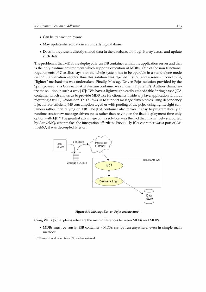
5.7. Communication middleware 113
• Can be transaction-aware.
• May update shared data in an underlying database.
• Does not represent directly shared data in the database, although it may access and updatesuch data.
The problem is that MDBs are deployed in an EJB container within the application server and thatis the only runtime environment which supports execution of MDBs. One of the non-functionalrequirements of GlassBus says that the whole system has to be operable in a stand-alone mode(without application server), thus this solution was rejected first off and a research concerning”lighter” mechanisms was undertaken. Finally, Message Driven Pojos solution provided by theSpring-based Java Connector Architecture container was chosen (Figure 5.7). Authors character-ize the solution in such a way [47]: ”We have a lightweight, easily embeddable Spring based JCAcontainer which allows us to provide MDB like functionality inside any Java application withoutrequiring a full EJB container. This allows us to support message driven pojos using dependencyinjection for efficient JMS consumption together with pooling of the pojos using lightweight con-tainers rather than relying on EJB. The JCA container also makes it easy to programatically atruntime create new message driven pojos rather than relying on the fixed deployment-time onlyoption with EJB.” The greatest advantage of this solution was the fact that it is natively supportedby ActiveMQ, what makes the integration effortless. Previously JCA container was a part of Ac-tiveMQ, it was decoupled later on.
Figure 5.7: Message Driven Pojos architecture27
Craig Walls [55] explains what are the main differences between MDBs and MDPs:
• MDBs must be run in EJB container - MDPs can be run anywhere, even in simple mainmethod;
27Figure downloaded from [59] and redesigned.
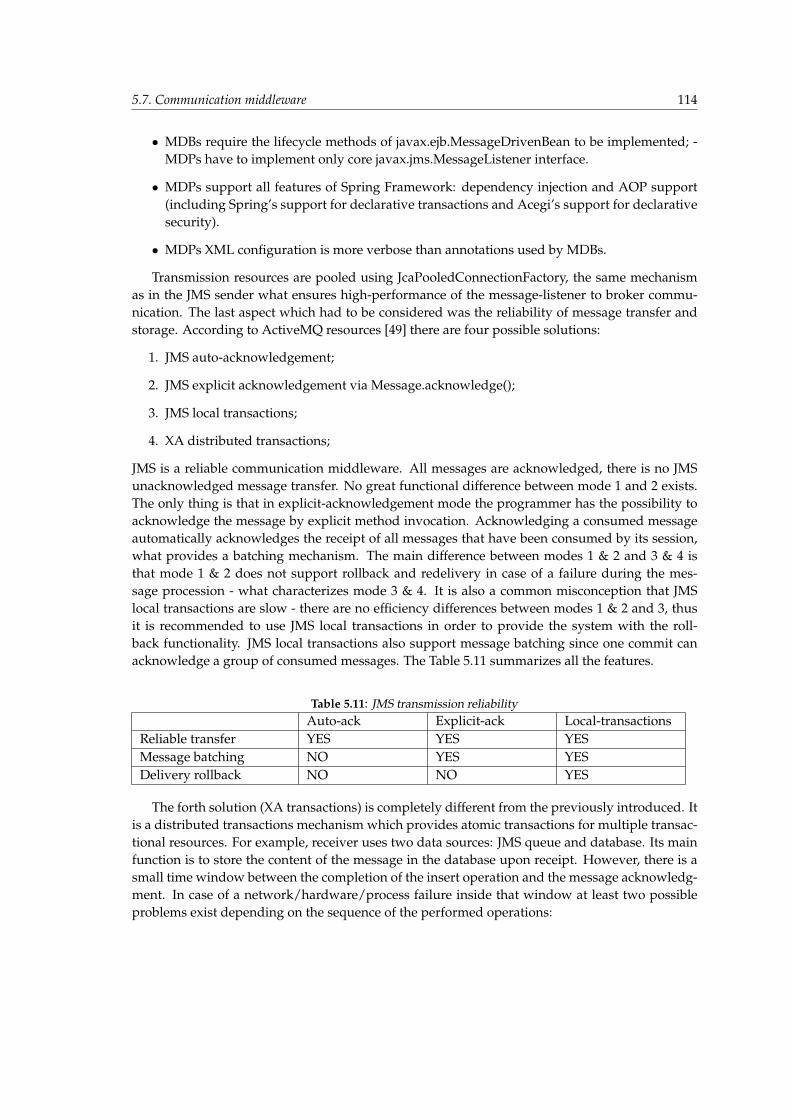
5.7. Communication middleware 114
• MDBs require the lifecycle methods of javax.ejb.MessageDrivenBean to be implemented; -MDPs have to implement only core javax.jms.MessageListener interface.
• MDPs support all features of Spring Framework: dependency injection and AOP support(including Spring’s support for declarative transactions and Acegi’s support for declarativesecurity).
• MDPs XML configuration is more verbose than annotations used by MDBs.
Transmission resources are pooled using JcaPooledConnectionFactory, the same mechanismas in the JMS sender what ensures high-performance of the message-listener to broker commu-nication. The last aspect which had to be considered was the reliability of message transfer andstorage. According to ActiveMQ resources [49] there are four possible solutions:
1. JMS auto-acknowledgement;
2. JMS explicit acknowledgement via Message.acknowledge();
3. JMS local transactions;
4. XA distributed transactions;
JMS is a reliable communication middleware. All messages are acknowledged, there is no JMSunacknowledged message transfer. No great functional difference between mode 1 and 2 exists.The only thing is that in explicit-acknowledgement mode the programmer has the possibility toacknowledge the message by explicit method invocation. Acknowledging a consumed messageautomatically acknowledges the receipt of all messages that have been consumed by its session,what provides a batching mechanism. The main difference between modes 1 & 2 and 3 & 4 isthat mode 1 & 2 does not support rollback and redelivery in case of a failure during the mes-sage procession - what characterizes mode 3 & 4. It is also a common misconception that JMSlocal transactions are slow - there are no efficiency differences between modes 1 & 2 and 3, thusit is recommended to use JMS local transactions in order to provide the system with the roll-back functionality. JMS local transactions also support message batching since one commit canacknowledge a group of consumed messages. The Table 5.11 summarizes all the features.
Table 5.11: JMS transmission reliabilityAuto-ack Explicit-ack Local-transactions
Reliable transfer YES YES YESMessage batching NO YES YESDelivery rollback NO NO YES
The forth solution (XA transactions) is completely different from the previously introduced. Itis a distributed transactions mechanism which provides atomic transactions for multiple transac-tional resources. For example, receiver uses two data sources: JMS queue and database. Its mainfunction is to store the content of the message in the database upon receipt. However, there is asmall time window between the completion of the insert operation and the message acknowledg-ment. In case of a network/hardware/process failure inside that window at least two possibleproblems exist depending on the sequence of the performed operations:
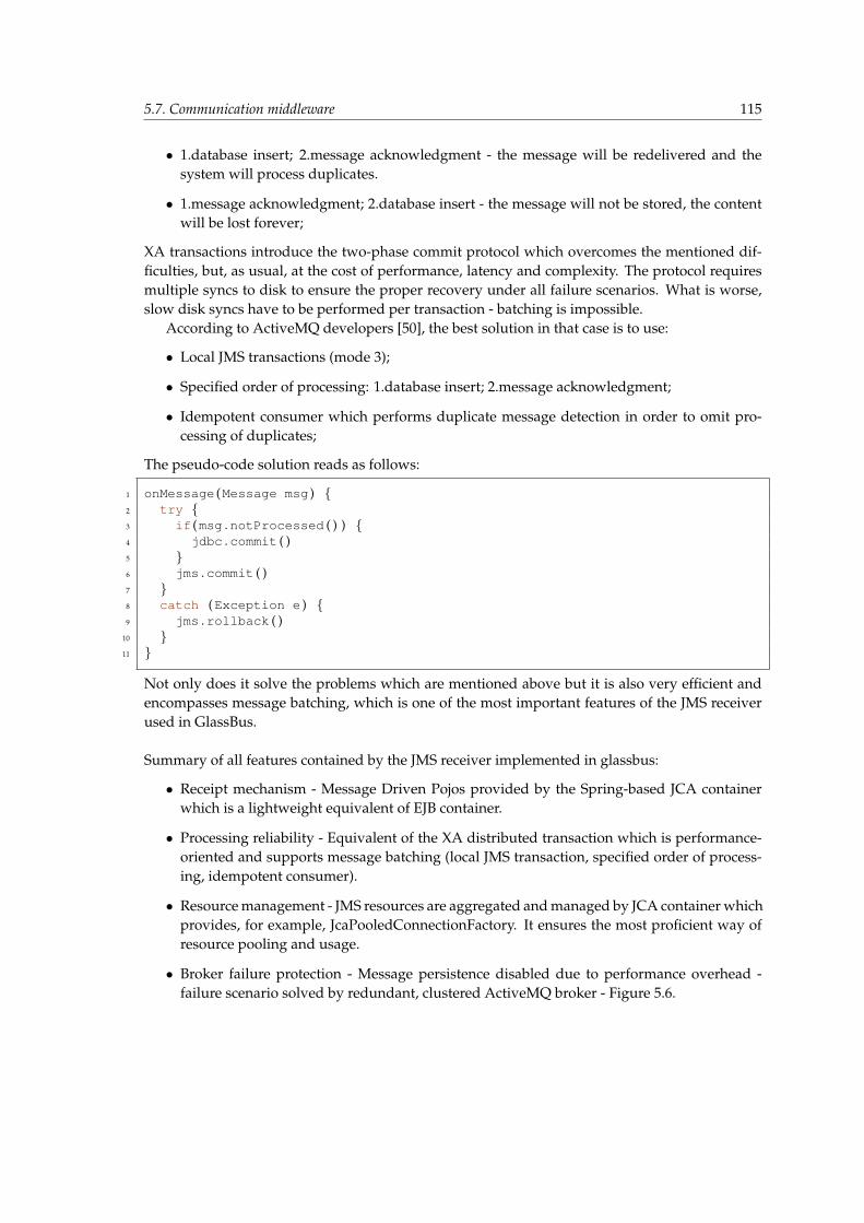
5.7. Communication middleware 115
• 1.database insert; 2.message acknowledgment - the message will be redelivered and thesystem will process duplicates.
• 1.message acknowledgment; 2.database insert - the message will not be stored, the contentwill be lost forever;
XA transactions introduce the two-phase commit protocol which overcomes the mentioned dif-ficulties, but, as usual, at the cost of performance, latency and complexity. The protocol requiresmultiple syncs to disk to ensure the proper recovery under all failure scenarios. What is worse,slow disk syncs have to be performed per transaction - batching is impossible.
According to ActiveMQ developers [50], the best solution in that case is to use:
• Local JMS transactions (mode 3);
• Specified order of processing: 1.database insert; 2.message acknowledgment;
• Idempotent consumer which performs duplicate message detection in order to omit pro-cessing of duplicates;
The pseudo-code solution reads as follows:
1 onMessage (Message msg ) {2 try {3 if (msg .notProcessed ( ) ) {4 jdbc .commit ( )5 }6 jms .commit ( )7 }8 catch (Exception e ) {9 jms .rollback ( )
10 }11 }
Not only does it solve the problems which are mentioned above but it is also very efficient andencompasses message batching, which is one of the most important features of the JMS receiverused in GlassBus.
Summary of all features contained by the JMS receiver implemented in glassbus:
• Receipt mechanism - Message Driven Pojos provided by the Spring-based JCA containerwhich is a lightweight equivalent of EJB container.
• Processing reliability - Equivalent of the XA distributed transaction which is performance-oriented and supports message batching (local JMS transaction, specified order of process-ing, idempotent consumer).
• Resource management - JMS resources are aggregated and managed by JCA container whichprovides, for example, JcaPooledConnectionFactory. It ensures the most proficient way ofresource pooling and usage.
• Broker failure protection - Message persistence disabled due to performance overhead -failure scenario solved by redundant, clustered ActiveMQ broker - Figure 5.6.
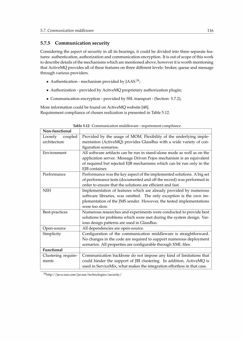
5.7. Communication middleware 116
5.7.5 Communication security
Considering the aspect of security in all its bearings, it could be divided into three separate fea-tures: authentication, authorization and communication encryption. It is out of scope of this workto describe details of the mechanisms which are mentioned above, however it is worth mentioningthat ActiveMQ provides all of these features on three different levels: broker, queue and messagethrough various providers.
• Authentication - mechanism provided by JAAS 28;
• Authorization - provided by AcitveMQ proprietary authorization plugin;
• Communication encryption - provided by SSL transport - (Section: 5.7.2);
More information could be found on ActiveMQ website [48].Requirement compliance of chosen realization is presented in Table 5.12.
Table 5.12: Communication middleware - requirement complianceNon-functionalLoosely coupledarchitecture
Provided by the usage of MOM. Flexibility of the underlying imple-mentation (ActiveMQ) provides GlassBus with a wide variety of con-figuration scenarios.
Environment All software artifacts can be run in stand-alone mode as well as on theapplication server. Message Driven Pojos mechanism is an equivalentof required but rejected EJB mechanisms which can be run only in theEJB container.
Performance Performance was the key aspect of the implemented solutions. A big setof performance tests (documented and off the record) was performed inorder to ensure that the solutions are efficient and fast.
NIH Implementation of features which are already provided by numeroussoftware libraries, was omitted. The only exception is the own im-plementation of the JMS sender. However, the tested implementationswere too slow.
Best-practices Numerous researches and experiments were conducted to provide bestsolutions for problems which were met during the system design. Var-ious design patterns are used in GlassBus.
Open-source All dependencies are open-source.Simplicity Configuration of the communication middleware is straightforward.
No changes in the code are required to support numerous deploymentscenarios. All properties are configurable through XML files.
FunctionalClustering require-ments
Communication backbone do not impose any kind of limitations thatcould hinder the support of JBI clustering. In addition, ActiveMQ isused in ServiceMix, what makes the integration effortless in that case.
28http://java.sun.com/javase/technologies/security/
5.8. Management middleware 117
5.8 Management middleware
The first section of JBI Status Quo (3.3.1) delineates that the specification covers rather the man-agement than monitoring concerns. The result of that is some management infrastructure thatmust be provided by every JBI implementation. The same section cites the JBI specification andproves that the bus’s clustering and distribution are not standardized. It is therefore not surpris-ing that the management framework defined in JBI is not suitable for scenarios of clustering inOpenESB and ServiceMix.
OpenESB and ServiceMix analysis against this issue reveled non-trivial impediments. Bothbuses provide JMX interfaces by means of widely used RMI connectors, the requirement of whichis binding to specific IP number and port. Additionally, the connector is protected with a username and password that is configured by the particular container’s administrator. It is easyto imagine a cluster encompassing dozens of buses, each with its own ip, port, user name andpassword of RMI connector. Such infrastructure is highly unmanageable, because central admin-istration tool needs knowledge about RMI connector’s details, which can be the subject of moreor less often changes. Another shortcoming comes from the direct localization binding, whichimplies violation of the loosely-coupling paradigm. The depicted implications are not compliantwith GlassBus requirements. Therefore, they are overcome by proper management middleware.
5.8.1 Possible options
The previous section discusses several options of conducting communication between GlassBuscomponents. The shortcomings of solutions based on sockets or RMI are presented. The pro-posed communication middleware subjects to a sole monitoring issue where information flowdirection is mostly from the Agent to the Engine. The management slightly differs because itsspecificity requires both communication directions - querying and passing of management pa-rameters from the Engine to the Agent is necessary. However, the difference does not prevent toincorporate conclusions about the MOM supremacy, which resulted in using MOM for the man-agement realization. It allows to maintain the GlassBus loosely-coupling and removes the need ofcombining and integrating different middleware mechanisms. The result is a coherent monitor-ing/management middleware. The most convenient incorporation of MOM into management issimply using a communication middleware defined earlier - network of ActiveMQ brokers - andbuilding management on top of it.
After the final choice of the mechanism for conducting management, a detailed realizationof passing management data has to be proposed. The following options have been taken intoaccount:
• XML over JMS — The data is enclosed in XML files, which are sent by means of commu-nication middleware. It forces to define some protocol which would provide XML schemabased syntactical definition and semantical interpretation enclosed in a parser logic. Sepa-rate parsers would have to be implemented on the agent’s and engine’s sides. The speci-ficity of the management requires employing the request-response pattern, which is neededwhile engine gets or sets values of particular attributes. It implies introduction of mecha-nism realizing request-response through MOM, which comes to implementation of correla-tion between messages sent as requests and those sent in response. Additionally, features
5.8. Management middleware 118
of reliability: resending and response timeouts are needed for the mechanism’s complete-ness. Such solution can be conceived as a capability of the method invocation built on topof message-oriented middleware.
• JMX over JMS — This approach extends the first idea by adding the abstraction of JMX. Thisimplies all the above-mentioned elements: communication protocol (it does not have to beXML), message parser, message interpreter and a message reliable correlator used to acquirerequest-response which is used to method invocation establishment. However, this solutionis more management-oriented. It allows for natural extension of the mechanism built intoServiceMix and OpenESB. Existing MBeans are simply exposed by a MBean Server usingJMS transfer protocol. Therefore, no additional logic mapping parsed XML to JBI MBeansis needed.
Both proposed solutions are not trivial to implement, but additional extensions provided bythe JMX over JMS results in its higher implementation complexity. However, it is undeniable thatthe latter solution provides a mechanism superior to the first one. Finally, it has been decided thatGlassBus will be equipped with the JMX over JMS management middleware. The decision wasmotivated by discovering a framework that allows to conduct it.
5.8.2 Realisation
The Lingo framework [42] has been identified as being ideal (and probably the only one) for re-alization of JMX over JMS. The framework describes itself as: ”lightweight POJO based remotingand messaging library, which extends it to support JMS”. Among the wide range of capabili-ties, Lingo provides a synchronous request-response (like RMI) message pattern which has beenidentified as being crucial for both XML and JMX over JMS. Furthermore, Lingo provides a ready-to-use mechanism of JMX over JMS 29, which allows to expose any MBean and to access it througha proxy on the client’s side using bare JMX interfaces. The additional Lingo’s advantage is Ac-tiveMQ dependency. Employing ActiveMQ in communication middleware implies that usingLingo (management middleware) on top of ActiveMQ (communication middleware) is straight-forward and does not cause any integration problems.
Unfortunately, recently Lingo has not been under active development - last version was re-leased in October 2006. It was probably the reason for some Lingo’s defects that had to be solvedin order to use it for the GlassBus’s purposes:
• Lingo provides the capability of binding MBeanServer to specific Topic name by means ofthe environment properties: destinationGroupName and destinationServerName. Unfor-tunately, the mechanism extracting these properties and applying them was broken anddemanded patching the Lingo’s code.
• Bug in waiting for response timeout in Topic-based communication resulting in hang-up. Itwas fixed by patching the Lingo code.
• Lingo was using ActiveMQ Topics for means of communication, which provides function-ality of aggregating results from operations or queries on MBeans exposed by MBeanServerthat Lingo connects to. Such functionality was not needed by GlassBus and topics have
29http://lingo.codehaus.org/JMX+over+JMS

5.8. Management middleware 119
been identified as being less reliable than queues. The Lingo code has been patched, allow-ing GlassBus management to be enhanced by the reliability of JMS queues.
• Some problems with ActiveMQ’s temporary queues, which are used to conduct request-response pattern, have been identified. It has been discovered that ActiveMQ versions ear-lier then 5.x do not provide usable duplex communication feature, therefore connecting intonetwork of brokers needed a significant amount of time. It has taken into account the designof GlassBus’s Agent and Engine.
After overcoming problems encountered in Lingo GlassBus management, the middleware wasready for establishing further design details.
Architecture of management and monitoring
When introducing the management requirements in this section only the GlassBus-Agents man-aging was taken into account. However, the JMX over JMS capabilities with method invocationamong them, allow to realize broader functionalities. When designing Agent and Engine inter-actions it was concluded that Agents cannot simply start to send monitoring information prior tosome previous preparation. The need of agent into engine registration procedure has been iden-tified and JMX over JMS allows to handle this task. In order to achieve this, not only Agents, butalso Engine has to expose its MBeanServer by means of communication middleware. Therefore,the final architecture assumes that every GlassBus component is equipped with the capability ofboth exposing and accessing MBeans in a loosely-coupled, message-oriented way. Additionally,each component is uniquely named by a simple string, which provides an addressing mechanism.It allowed to elaborate an algorithm sketch of the agent’s and engine’s behavior. The algorithm ispresented in details on Sequence diagrams in Section 6.3.6.Requirement compliance of chosen realization is presented in Table 5.13.
Table 5.13: Management requirement complianceNon-FuncUsefulness The GlassBus user can avoid accessing MBeans of clustered JBIs by inconvenient
RMI connectors.JSR-based GlassBus retains all JBI MBeans thanks to forwarding them to the Engine.Simplicity No middleware implementation was needed (apart from Lingo patching).Loosely-Coupling
Completely retained by using communication middleware.
Highly man-ageable
Achieved by Preserving JMX advantages.
NIH Not implementing functionalities already provided by Lingo.Open-sourcedependencies
Lingo is open-sourced - uses Apache 2.0 license.
FuncCluster JMX over JMS can manage federations and clusters easily.
5.9. Hierarchical Data Management 120
5.9 Hierarchical Data Management
JBI topology consists of many elements which remain in hierarchical relationships. For example:JBI instance is a part of a cluster, SA is a part of a JBI instance, SU resides in a SA, endpoint is a partof SU, set of operations form an endpoint, etc. GlassBus is supposed to trace, store and providethe external client with the topology information; therefore during the design some conceptualproblem were faced and solved, in order to encompass all aforementioned capabilities. Threemain problems which occurred are:
• What data structure should be used to store the JBI topology information during runtime?
• How to persist the topology information?
• How to provide the external client with the topology information?
5.9.1 Possible solutions
The introduced problem, which could actually be defined as the quandary of creating, managingand persisting hierarchical data, was never a trivial one. Java programming language does notprovide the generic, hierarchical data collections such as graphs and trees, thus a surrogate, whichis proprietary implemented, has to be introduced every time. The format and the nature of thedata are crucial aspects while choosing the best fitting option. Let us consider the functionalrequirements of the needed solution on the lower abstraction level. It is possible to divide theproblem into two separate parts:
• Data management:
– Data kind - topology information remaining in hierarchical relationships;
– Data type - Java primitive data type, mainly String;
– Data operations - addition of new data to the specified place (parent, child), searching(eg. all disabled SUs), modifying (eg. changing the state of SU), deleting (eg. removingundeployed artifacts);
– Data exposition - topology information is exposed to external clients using primitivedata format;
• Data persistence - topology information is gathered by monitoring agents; then informationis sent to monitoring engine which stores it in a datastore;
One of the first-thought solutions is to code the own, proprietary implementation. There wouldbe two steps of the code design: implementation of the generic data structure and its function-alities as well as implementation of the domain classes and the persistence code. The solutionwould be very flexible as it can be tuned to match all the distinctive requirements. Data struc-ture would contain all demanded methods, providing sophisticated management functionalitiesand the persistence would be also incorporated, forming a monolithic solution. However, pre-sented idea does not comply with the best practices of software design. Usually, implementationof a proprietary solution of a commonly known problem is expensive, mundane, redundant anderror-prone. It could take hours to fix all the bugs and tune the performance to the long-expected
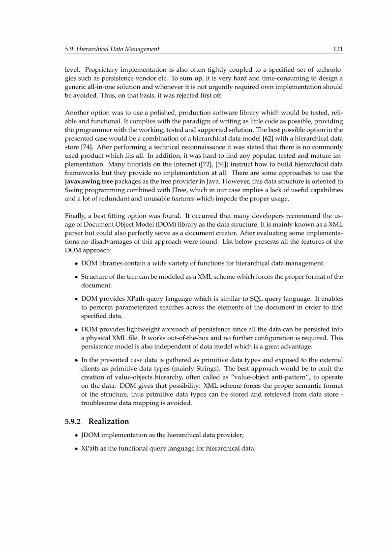
5.9. Hierarchical Data Management 121
level. Proprietary implementation is also often tightly coupled to a specified set of technolo-gies such as persistence vendor etc. To sum up, it is very hard and time-consuming to design ageneric all-in-one solution and whenever it is not urgently required own implementation shouldbe avoided. Thus, on that basis, it was rejected first off.
Another option was to use a polished, production software library which would be tested, reli-able and functional. It complies with the paradigm of writing as little code as possible, providingthe programmer with the working, tested and supported solution. The best possible option in thepresented case would be a combination of a hierarchical data model [62] with a hierarchical datastore [74]. After performing a technical reconnaissance it was stated that there is no commonlyused product which fits all. In addition, it was hard to find any popular, tested and mature im-plementation. Many tutorials on the Internet ([72], [54]) instruct how to build hierarchical dataframeworks but they provide no implementation at all. There are some approaches to use thejavax.swing.tree packages as the tree provider in Java. However, this data structure is oriented toSwing programming combined with JTree, which in our case implies a lack of useful capabilitiesand a lot of redundant and unusable features which impede the proper usage.
Finally, a best fitting option was found. It occurred that many developers recommend the us-age of Document Object Model (DOM) library as the data structure. It is mainly known as a XMLparser but could also perfectly serve as a document creator. After evaluating some implementa-tions no disadvantages of this approach were found. List below presents all the features of theDOM approach:
• DOM libraries contain a wide variety of functions for hierarchical data management.
• Structure of the tree can be modeled as a XML scheme which forces the proper format of thedocument.
• DOM provides XPath query language which is similar to SQL query language. It enablesto perform parameterized searches across the elements of the document in order to findspecified data.
• DOM provides lightweight approach of persistence since all the data can be persisted intoa physical XML file. It works out-of-the-box and no further configuration is required. Thispersistence model is also independent of data model which is a great advantage.
• In the presented case data is gathered as primitive data types and exposed to the externalclients as primitive data types (mainly Strings). The best approach would be to omit thecreation of value-objects hierarchy, often called as ”value-object anti-pattern”, to operateon the data. DOM gives that possibility: XML scheme forces the proper semantic formatof the structure, thus primitive data types can be stored and retrieved from data store -troublesome data mapping is avoided.
5.9.2 Realization
• JDOM implementation as the hierarchical data provider;
• XPath as the functional query language for hierarchical data;

5.10. Installation and runtime environments 122
• XML file as a hierarchical data store;
Requirement compliance of chosen realization is presented in Table 5.14.
Table 5.14: Hierarchical data - requirement complianceNon-functional”Best-practices” Design is compliant with best-practices of software engineering.Open-source All dependencies are open-source.FunctionalTopology and Flowinformation
This experiment is a part of topology functionality realization.
5.10 Installation and runtime environments
It has been stressed many times that the essential GlasBus’s goal is JBI compliance. This experi-ment, however, does not relate directly to it. The aim of this experiment is to provide a solution fordeploying GlassBus on enterprise infrastructure built from either ServiceMix or OpenESB buses.The requirement for deployment is to create one user-friendly, coherent tool that will overcomedifficulty of the two different buses’ environments: application server and stand-alone. Addition-ally, the tool has to support both deployment scenarios:
• single monolithic bus;
• distributed federation of buses;
5.10.1 Deployment assumptions
As it has been introduced earlier in Chapter 4, GlassBus encompasses two main components:GlassBus-Agent and GlassBus-Engine. The Agent has to be deployed to each bus, the monitoringof which is desirable, while the Engine’s assumption is the deployment to some external resourcededicated to gathering, processing and exposing monitoring data. Agent integration is combinedof the following steps:
1. installing all needed dependencies;
2. installing appropriate aspects for each bus;
3. configuration of information acquiring mechanism - AspectJ weaving described in Section 5.3;
4. configuration of logging framework;
Additional configuration of Agent’s initialization procedure is not needed because the JBITopol-ogyComponentInterceptor aspect (Listing A.5) described earlier (Section 5.4) listens for topologychanges and launches GlassBus-Agent as soon as one of bus’s JBI components initializes. Integra-tion details of GlassBus-Engine will depend on the particular environment.
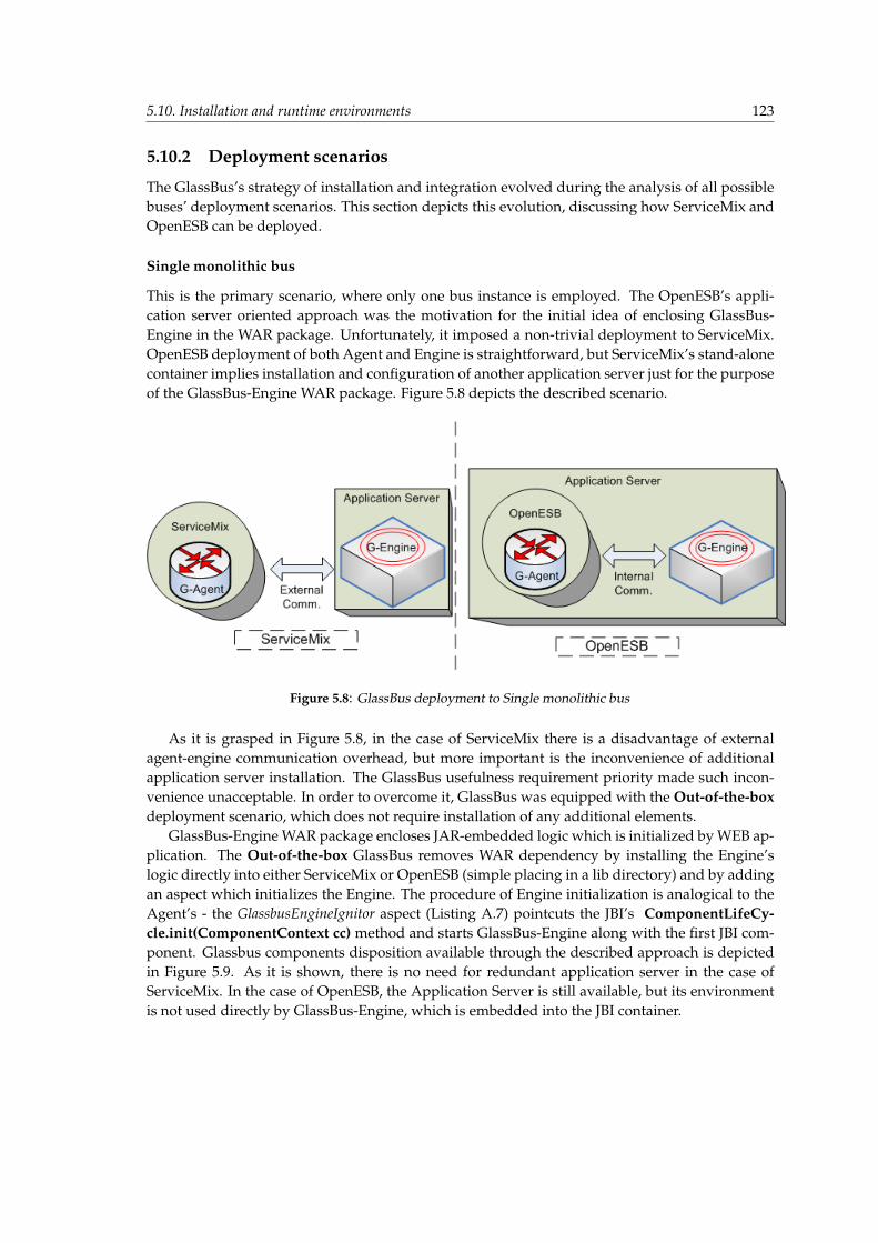
5.10. Installation and runtime environments 123
5.10.2 Deployment scenarios
The GlassBus’s strategy of installation and integration evolved during the analysis of all possiblebuses’ deployment scenarios. This section depicts this evolution, discussing how ServiceMix andOpenESB can be deployed.
Single monolithic bus
This is the primary scenario, where only one bus instance is employed. The OpenESB’s appli-cation server oriented approach was the motivation for the initial idea of enclosing GlassBus-Engine in the WAR package. Unfortunately, it imposed a non-trivial deployment to ServiceMix.OpenESB deployment of both Agent and Engine is straightforward, but ServiceMix’s stand-alonecontainer implies installation and configuration of another application server just for the purposeof the GlassBus-Engine WAR package. Figure 5.8 depicts the described scenario.
Figure 5.8: GlassBus deployment to Single monolithic bus
As it is grasped in Figure 5.8, in the case of ServiceMix there is a disadvantage of externalagent-engine communication overhead, but more important is the inconvenience of additionalapplication server installation. The GlassBus usefulness requirement priority made such incon-venience unacceptable. In order to overcome it, GlassBus was equipped with the Out-of-the-boxdeployment scenario, which does not require installation of any additional elements.
GlassBus-Engine WAR package encloses JAR-embedded logic which is initialized by WEB ap-plication. The Out-of-the-box GlassBus removes WAR dependency by installing the Engine’slogic directly into either ServiceMix or OpenESB (simple placing in a lib directory) and by addingan aspect which initializes the Engine. The procedure of Engine initialization is analogical to theAgent’s - the GlassbusEngineIgnitor aspect (Listing A.7) pointcuts the JBI’s ComponentLifeCy-cle.init(ComponentContext cc) method and starts GlassBus-Engine along with the first JBI com-ponent. Glassbus components disposition available through the described approach is depictedin Figure 5.9. As it is shown, there is no need for redundant application server in the case ofServiceMix. In the case of OpenESB, the Application Server is still available, but its environmentis not used directly by GlassBus-Engine, which is embedded into the JBI container.
5.10. Installation and runtime environments 124
Figure 5.9: GlassBus single out-of-the-box deployment
The Out-of-the-box GlassBus’s feature allows to maintain installation simplicity and removesthe need of external communication in the single monolithic bus scenario. The feature makespossible, but does not impose, the in-bus Engine deployment. The user can choose the mostconvenient scenario. In ServiceMix in-bus option is obviously more convenient, but in the case ofOpenESB it is difficult to judge what would be more preferable by the user.
Distributed cluster of buses
Complying with the requirement of cluster monitoring support, the deployment mechanism al-lows to integrate GlassBus into existing OpenESB or ServiceMix clusters (cf. clustering in Section3.3.4). Mechanisms described in the single monolithic bus scenario are perfectly enough to supportthe clustering case, which can be covered in several possible ways:
• OpenESB
1. GlassBus-Agent is deployed to each instance of OpenESB in the cluster. GlassBus-Engine WAR package is deployed to an external application server.
2. GlassBus-Agent is deployed to each instance of OpenESB in the cluster. GlassBus-Engine is deployed in the Out-of-the-box mode to one of the clustered applicationservers, which becomes the main monitoring node.
• ServiceMix
1. GlassBus-Agent is deployed to each instance of federated ServiceMixs. Separate notfederated ServiceMix instance is used just for the purpose of GlassBus-Engine Out-of-the-box deployment.
2. GlassBus-Agent is deployed to each instance of federated ServiceMixs. GlassBus-Engineis deployed to a separate external Application Server.
5.10. Installation and runtime environments 125
3. GlassBus-Agent is deployed to each instance of federated ServiceMixs. GlassBus-Engineis deployed to one of the instances from federation, which becomes the main monitor-ing node.
The first option in OpenESB and the first two in ServiceMix are probably more adequate to largerbuses clusters where scale of monitoring information requires separate resources for gatheringand processing. The latter options are suitable for small clusters where they are applied by pro-moting one of the nodes to monitoring center. The user can freely choose the most convenientscenario.
5.10.3 Realization
It has been decided that the described functionalities will be covered by a separate component:GlassBus-Installer. It is enclosed in an executable jar file allowing therefore for a straightforwarddownloading and installation. GlassBus-Installer features the following functionalities:
• While executed in the root bus directory (either ServiceMix or OpenESB) or executed withpath argument pointing to such a root, it can automatically detect the bus type and GlassBuscomponents already deployed to it.
• Installation procedure is performed interactively - the user is questioned about componentshe/she wishes to install and to initially configure.
• the following components can be installed:
– GlassBus-Agent into ServiceMix, OpenESB;
– GlassBus-Engine into ServiceMix as out-of-the-box, OpenESB as out-of-the-box;
The deployment of GlassBus-Engine WAR package is left to the user. It can be achieved by anymeans available in the particular application server.GlassBus-Installer allows for instant out-of-the-box deployment. The user downloads the GlassBus-installer jar and executes it in a bus’s root directory. While questioned he replies that both agentand engine should be embedded into the bus. In two minutes time everything is ready. In dis-tributed scenario GlassBus-Agent has to be manually installed to each node that is going to bemonitored. Fortunately the GlassBus-Installer simplicity allows to easily script installation taskand execute it in automatic manner (for details please refer to Section 6.6).Requirement compliance of chosen realization is presented in Table 5.15.
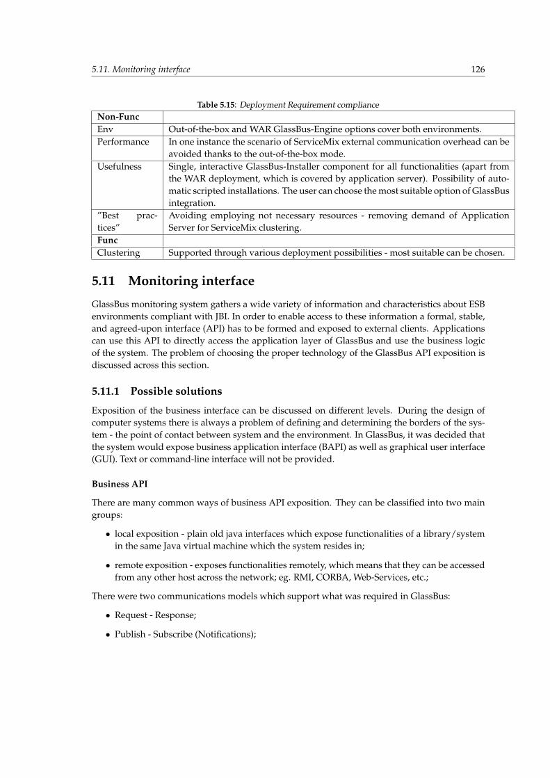
5.11. Monitoring interface 126
Table 5.15: Deployment Requirement complianceNon-FuncEnv Out-of-the-box and WAR GlassBus-Engine options cover both environments.Performance In one instance the scenario of ServiceMix external communication overhead can be
avoided thanks to the out-of-the-box mode.Usefulness Single, interactive GlassBus-Installer component for all functionalities (apart from
the WAR deployment, which is covered by application server). Possibility of auto-matic scripted installations. The user can choose the most suitable option of GlassBusintegration.
”Best prac-tices”
Avoiding employing not necessary resources - removing demand of ApplicationServer for ServiceMix clustering.
FuncClustering Supported through various deployment possibilities - most suitable can be chosen.
5.11 Monitoring interface
GlassBus monitoring system gathers a wide variety of information and characteristics about ESBenvironments compliant with JBI. In order to enable access to these information a formal, stable,and agreed-upon interface (API) has to be formed and exposed to external clients. Applicationscan use this API to directly access the application layer of GlassBus and use the business logicof the system. The problem of choosing the proper technology of the GlassBus API exposition isdiscussed across this section.
5.11.1 Possible solutions
Exposition of the business interface can be discussed on different levels. During the design ofcomputer systems there is always a problem of defining and determining the borders of the sys-tem - the point of contact between system and the environment. In GlassBus, it was decided thatthe system would expose business application interface (BAPI) as well as graphical user interface(GUI). Text or command-line interface will not be provided.
Business API
There are many common ways of business API exposition. They can be classified into two maingroups:
• local exposition - plain old java interfaces which expose functionalities of a library/systemin the same Java virtual machine which the system resides in;
• remote exposition - exposes functionalities remotely, which means that they can be accessedfrom any other host across the network; eg. RMI, CORBA, Web-Services, etc.;
There were two communications models which support what was required in GlassBus:
• Request - Response;
• Publish - Subscribe (Notifications);

5.11. Monitoring interface 127
After a short evaluation, it was decided that Java Management Extensions technology would beused. Not only does it fulfill all the requirements, as all the communication models are provided,but it also provides the abstraction over communication protocol. There is a set of supported,most popular communication protocols, which can be extended in an unlimited fashion usingGeneric Connection Architecture. Furthermore, the chosen technology is also oriented to moni-toring and management, which greatly fits in. Coming to an end, simple, standardized tools ofgenerating statistics and charts from JMX beans exist, which gives the possibility to avoid redun-dant code creation.
It is also worth mentioning that GlassBus architecture does not limit the exposition of businesslogic to any kind of technology. The API is designed according to the best practices of object-oriented software design, which enables a developer to expose the API in a straightforward wayusing any kind of proper technologies.
Graphical User Interface
The realization of graphical interface is an additional feature of GlassBus. It is an end-to-end inter-face which enables an external user to interact with a system using graphical icons and indicators.GUI can be built from scratch or built on the top of a Rich Client Platform (RCP). According tomany sources, there are many advantages of RCP [69]:
• well tested, solid foundation;
• provides: windows and panels management, plugin support, messaging infrastructure, ser-vice discovery, etc.;
• incorporates: help system, log system, etc.;
It was decided that Netbeans Rich Client Platform would be used [69] since it is well documentedand many tutorials exist. This approach would be also compliant with OpenESB as its all graphi-cal tools are provided as Netbeans plugins.
5.11.2 Realization
• BAPI - exposed by Java Management Extensions beans which are oriented to monitoringinformation exposition. It is referred in the rest of thesis as External monitoring interface.
• GUI - realized on the top of Netbeasn RCP as a netbeans plugin.
Requirement compliance of chosen realization is presented in Table 5.16.
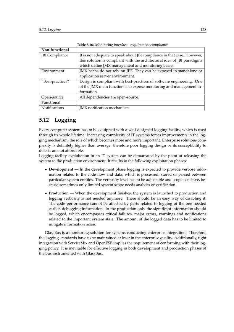
5.12. Logging 128
Table 5.16: Monitoring interface - requirement complianceNon-functionalJBI Compliance It is not adequate to speak about JBI compliance in that case. However,
this solution is compliant with the architectural idea of JBI paradigmswhich define JMX management and monitoring beans.
Environment JMX beans do not rely on JEE. They can be exposed in standalone orapplication server environment.
”Best-practices” Design is compliant with best-practices of software engineering. Oneof the JMX main function is to expose monitoring and management in-formation.
Open-source All dependencies are open-source.FunctionalNotifications JMX notification mechanism.
5.12 Logging
Every computer system has to be equipped with a well-designed logging facility, which is usedthrough its whole lifetime. Increasing complexity of IT systems forces improvements in the log-ging mechanism, the role of which becomes more and more important. Enterprise solutions com-plexity is definitely higher than average, therefore poor logging design or its susceptibility todefects are not affordable.Logging facility exploitation in an IT system can be demarcated by the point of releasing thesystem to the production environment. It results in the following exploitation phases:
• Development — In the development phase logging is expected to provide verbose infor-mation related to the code flow and data, which is processed, stored or passed betweenparticular system entities. The verbosity level has to be adjustable and scope-sensitive, be-cause sometimes only limited system scope needs analysis or verification.
• Production — When the development finishes, the system is launched to production andlogging verbosity is not needed anymore. There should be an easy way of disabling it.The code performance cannot be affected by parts related to logging of the one neededearlier, debugging information. In the production only the significant information shouldbe logged, which encompasses critical failures, major errors, warnings and notificationsrelated to the important system state. The amount of the logged data has to be limited tomitigate information noise.
GlassBus is a monitoring solution for systems conducting enterprise integration. Therefore,the logging standards have to be maintained at least in the enterprise quality. Additionally, tightintegration with ServiceMix and OpenESB implies the requirement of conforming with their log-ging policy. It is inevitable for effective logging in both development and production phases ofthe bus instrumented with GlassBus.
5.12. Logging 129
5.12.1 Possible options
The described logging facilities requirements are well-known and there are many logging frame-works for Java language which comply with them. The following options have been consideredfor the purpose of employing in GlassBus:
1. Log4j30 — the most popular Java logging framework. It can be treated as a logging standardwhich introduced terms like: Logger, Formatter, Appender, Filter, Logging Level.
2. Java Logging API31 — functionality of JRE introduced in Java 1.4. It was build on the basisof Log4j, but unfortunately it lacks many Log4j’s functionalities - e.g., there is a very limitednumber of appenders.
3. Own proprietary solution — implementation of simple logging framework complying withGlassBus’s requirements.
Implementation of own logging solution does not comply with ”Best practices” and does notfulfill the NIH requirements. There is no need of reinventing the wheel and implementing loggingframeworks, which are already available. Log4j seemed to be the best choice, but the alternativeof logging embedded into JRE could not be easily disregarded.
Before choosing the final logging framework, an analysis of logging in ServiceMix and Ope-nESB has been performed:
• ServiceMix — The bus uses the Log4j logging framework, but in an indirect way. The basiclogging interface is provided by Apache’s Java Commons Logging (JCL)32, which is actuallynot an implementation of a logging facility, but rather a thin abstraction layer which allowsto employ underneath any logging framework.
• OpenESB — The Sun’s solution employs the Log4j’s less powerful alternative - JDK Loggers,which is used in both GlassFish and OpenESB.
The differences between buses’ logging frameworks imply significant difficulty of equippingGlassBus with a solution that could be easily integrated with them.
An interesting JCL feature is the possibility of deferring logging framework choice, thereforeany of the aforementioned frameworks could be finally chosen and optionally further replacedaccording to the needs. Such approach most completely comply with the GlassBus’s require-ments - for example, the framework’s abstraction layer is a common design pattern, which isrecommended by software engineering best practices.
GlassFish Documentation 33 mentions the JCL usage, but does not recommend it: ”Applica-tion components may use the Apache Commons Logging Library to log messages. The platformstandard JSR-047 API, however, is recommended for better log configuration.” Despite this fact,it has been concluded that using commons logging allows to overcome the problem of the buses’logging frameworks differences. Therefore, it has been decided to employ JCL in GlassBus. Itgives the possibility of integration with Log4j in ServiceMix and Java Logging API in OpenESB.
30http://logging.apache.org/log4j/31http://java.sun.com/j2se/1.4.2/docs/guide/util/logging/32http://commons.apache.org/logging/33https://glassfish.dev.java.net/javaee5/docs/AG/abluj.html
5.12. Logging 130
5.12.2 Realization
Logging experimenting with JCL was restricted to an integration with Log4j. It was perfectlyenough for the purpose of this research and simply left the possibility of later integration withloggers from Java API in the scope of the solution’s improvements and future work. It implied in-tegration of Log4j into GlassFish, which turned out to be supportable by the container. Followingthe steps on GlassFish’s wiki 34 Log4j has been integrated with ease.
As described in sections: Information acquiring mechanism 5.3 and Installation and runtimeenvironment 5.10, GlassBus integration is performed by placing its jar-embedded logic into thebus’s lib directory. It does not allow to cleanly separate GlassBus logging from the configurationof the bus. It is not a problem in OpenESB, where Log4j is used only for GlassBus. Therefore,there is nothing to interfere with. Unfortunately, ServiceMix’s every component heavily dependson Log4j, which is why some integration strategy is indispensable.
It was concluded that the cleanest solution will be to simply modify the ServiceMix’s loggingconfiguration by adding appenders and loggers dedicated to GlassBus. A sample final configura-tion can be looked up in Listing A.10. Such an approach removes the requirement of embeddinglogging configuration into each GlassBus artifact, which would be totally unmanageable becauseof the sealing into jars.
This solution does not relate to GlassBus-Engine Web Application. Application servers pro-vide flexible way of separating logging internals of web application from that of the server. Log-ging of GlassBus-Engine web app. was solved by embedding Log4j dependencies into WARpackage therefore achieving total separation of logging infrastructure. The ease of WAR loggingembedding in the case of GlassBus-Engine did not prevent the full understanding of the complex-ity of the application servers’ logging environments, the essentials of which are described in CekiGulcu’s ”Supporting the Log4j RepositorySelector in Servlet Containers” article [86]. The authorexplains that the separation of WEB application logging is not trivial because simple embeddingof Log4j libraries in WAR can be overridden by libraries installed in the server scope (actually, itdepends on particular server implementation). The author proposes to override Log4j’s Reposito-rySelector, which would allow to maintain separate loggers hierarchies for each web application.It seemed to be the most complete solution. Currently, however, simple Log4j embedding com-plies with all GlassBus requirements, which is why it has finally been chosen. The solution can befurther improved in the future according to suggestions of Ceki Gulcu.
Integration of JCL was straightforward thanks to the automatic detecting Log4j availabilityand defaulting to it. No additional configuration was needed. JCL usage was restricted to twoclasses: LogFactory and Log. Equipping CLASS with logging was achieved by a schematic Logattribute:
private static final Log log = LogFactory.getLog(CLASS.class);
Java commons logging suggests logging best practices, which have been incorporated into Glass-Bus:
• Code Guards — each logging of INFO and lower level is preceded by checking if suchlogging should be performed. It allows to avoid log arguments evaluation when loggingshould not be performed.
34http://wiki.glassfish.java.net/Wiki.jsp?page=FaqCongifureLog4J
5.13. Conclusion 131
• Messages Priorities — ensuring that the log message severity is appropriate to its content.
• Default Message Priority — by default, messages of DEBUG and lower priorities shouldnot be logged.
• Info or Debug — maintaining a reasonable balance between the amount of info and debugmessages, so that information noise and lack of information in production environment canbe avoided.
• Logging Exceptions — assuring that exceptions are logged when necessary and that some-times it does not eliminate the requirement of rethrowing them.
Requirement compliance of chosen realization is presented in Table 5.17.
Table 5.17: Logging Requirement complianceNon-FuncEnv JCL and Log4j allows to cover both environments.Usefulness JCL does not need any configuration and Log4j can be easily adjusted through the
main container’s configuration modification. GlassBus-Engine WAR logging config-uration is separated and also easily adjustable.
”Best prac-tices”
JCL abstraction layer is in line with IT best practices. Additional logging specificpractices have been incorporated.
Open-sourcedependencies
JCL and Log4j are both licensed on Apache License Version 2.0 from January 200435.
Simplicity Introduction of complex RepositorySelector has been avoided thanks to a simple Log4jin-war embedding.
5.13 Conclusion
Albert Einstein’s maxim introduced in the chapter’s beginning was inspiration of so called ExperimentalDriven Development approach presented throughout the GlassBus Research. Subject’s complexity im-plied that only well documented experiments would be convincing proof for choosing best realizations ofdiscussed problems. The most important outcome of this chapter is related to particular realizations justi-fication, which was provided by means of requirements compliance extracts. Elements compliance can besummarized in following way:
• Information acquiring mechanism - Acquiring information by means of AOP crosscut allows to avoidthe need of the JBI container’s code modification. Simple installation of jars with aspects and runningcontainer with AspectJ weaver is sufficient for proper instrumentation.
• JBI monitoring mechanisms - The flexibility of AOP crosscut allowed for a straightforward designof JBI monitoring. It is based solely on methods from JBI interfaces documented in JSR-208, whichresults in the full compliance with JBI.
• Correlation heuristics - The previous two mechanisms allowed for realizing the heuristics that arefully JBI-compliant and non-invasive for the JBI code. Priority of JBI compliance pursuit resulted inmechanisms that do not always function properly - it was an inevitable trade-off.
5.13. Conclusion 132
• Persistence - This element had not the highest priority. The main goal was to maintain the level ofabstraction which will assure the ease of future replacement. The performance of chosen lightweightH2 DBMS was sufficient for the purpose of the research.
• Communication middleware - Fortunately, it was possible to propose a fully loosely-coupled mes-saging backbone. It was very important for the support of OpenESB and ServiceMix clustering.Additional advantage of the achieved loosely-coupling is an unequivocal demarcation between thebackbone and the code built upon it, which is not aware of the backbone distribution details. Evenmore important was the achievement of high sender performance, which allowed to avoid significantperformance deterioration of the running JBI container.
• Management middleware - The fact that the management is built on top of the communication mid-dleware implies the inheritance of its all advantages. The most important functionality is the abstrac-tion of the method invocation, which is realized by Lingo’s JMX over JMS.
• Hierarchical Data Management - Software engineering best practices was the main requirement,which have accompanied the realization of this element. It resulted in adapting well known XMLsolutions fitting perfectly for the management of hierarchical data.
• Installation and runtime environments - The main goal was a straightforward installation and con-figuration. It was the reason for introducing the out-of-the-box installation type, which not onlyprovides installation ease, but also boosts the single bus scenario performance in a significant way.
• Monitoring interface - In order to provide mechanism coherent with the current JBI managementlayer, the JMX technology has been chosen. The flexibility of JMX connectors implies that it iscurrently the most compatible way of exposing the monitoring and management interface.
• Logging - Chosen Java Commons Logging provided the widest range of possible underneath loggingframeworks. It gives the flexibility of adopting to ServiceMix and OpenESB, which use differentlogging libraries. Additionally, GlassBus maintains the best practices of logging.
Strict separation to different experiments is the reason for blurring the complete architecture, which encom-passes all discussed mechanisms. The next chapter tries to fill this gap by depicting a synthetic GlassBusview and pointing out the compliance of the mechanisms discussed above.
Chapter 6
GlassBus Implementation
For the things we have to learn before we can do them, we learn by doing them. Aristotle, Ancient GreekPhilosopher, Scientist and Physician.
6.1 Preamble
The previous chapter went through each element of the GlassBus solution, composing a strictly analyticalview of a system. Possible options, motivations and chosen realizations have been outlined, which providesa good basis for the synthetic presentation of the GlassBus’s implementation details enclosed in this chapter.
GlassBus implementation is opened with an overview of the architecture, which gathers all elementsdiscussed in the previous chapter and forms a complete distributed architecture of the GlassBus solution.The architecture diagram provides a good reference for the content of the next section, which focuses on thedetails of the particular GlassBus parts. Two main sections are related to a logical and physical structure.The more important logical structure describes various layers traversed by monitoring information. Theinformation is enclosed in a domain model and is gathered at the level of the GlassBus Agent. It is furtherpassed to GlassBus Engine for aggregation and analysis and is finally exposed by an external interface.This process is described throughout Sections 6.3.1, 6.3.2, 6.3.3, 6.3.4. For the purpose of readability, theinformation throughout the logical structure is divided into topology attributes and messaging attributes.The whole process can be managed by means described in the management and selectivity model (6.3.5).For a better understanding of the logical responsibilities of every component, invocation flows have beenprovided as the summary of the Logical structure section. The less important physical GlassBus structuredescribes the organization of the code and the relations between artifacts of the built process and the systemcomponents.
The two further Sections (6.5 and 6.6) are related to GlassBus configuration and installation. Fortu-nately, these processes are fairly straightforward allowing for a compact and informative description. Thechapter closes with an implementation status that points out the high complexity of JBI monitoring subjectand discusses its influence on the architecture and implementation. Finally, GlassBus performance teststhat prove usability for both ServiceMix and OpenESB JBI implementations are introduced.

6.2. Architecture Overview 134
6.2 Architecture Overview
The Diagram 6.1 shows the complete architecture of GlassBus, which combines the division intofunctional modules with their deployment and intercommunication.GlassBus encompasses two components:
• GlassBus-Agent;
• GlassBus-Engine;
In order to monitor the cluster of JBI containers, the Agent has to be installed into each container,while the Engine is deployed only once either to the Application Server or by being embeddedinto the JBI bus (for details cf. Chapter 5). As depicted in the diagram, the components are inter-connected by the Network of ActiveMQ brokers, which provides loosely-coupling, security andis extendible to any amount of monitored JBIs. It could be conceived that the GlassBus middle-ware is a bus constructed in parallel to the federation of the monitored JBI containers. Not everyGlassBus-Agent is aware of other Agents connected to the networks of brokers, but an intelligentcorrelation built into the Agent’s interceptors is able to track intra- and inter-containers in JBIbusiness transactions (described in correlation heuristics from Chapter 5).
The information gathered and correlated by interceptors is further enclosed in domain classes(presented in Section 6.3.1) and forwarded to GlassBus-Engine using the JMS Sender, which em-ploys the GlassBus middleware. The information is received and processed by the JMS receivermodule, which passes it to the Persistence module. Then, the data is properly prepared andverified with the information already stored. The abstraction layer - JPA - is used to persist thevalidated data. Persisted information is exposed by an external JMX interface.
In parallel to transferring and processing the chain of monitoring data, an interaction betweenthe Engine’s and Agent’s management layers is continuously performed. At the beginning, theAgent has to register in the Engine by means of one of its MBeans. The Engine is then capableof forwarding the Agent’s JBI MBeans and exposing them to the Monitoring Administrator. Addi-tionally, the Agent and the Engine keep querying each other to assure mutual accessibility. Thewhole management is realized through the JMS over JMX - Lingo framework.
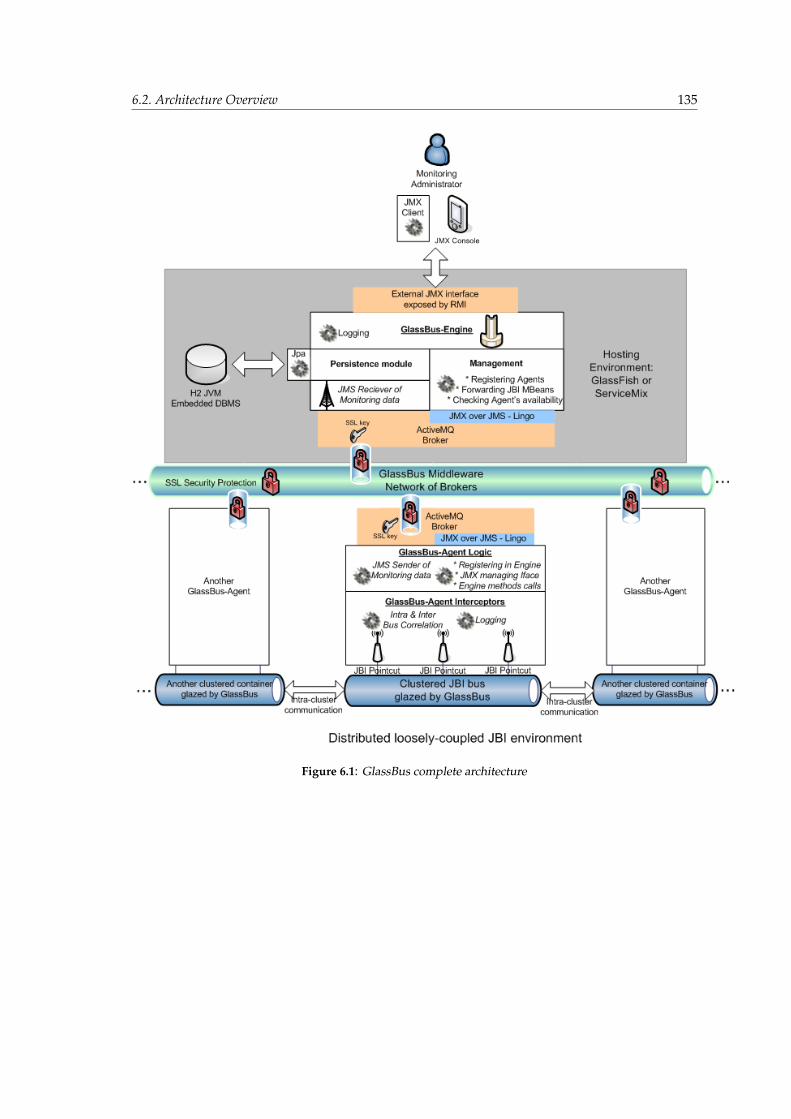
6.2. Architecture Overview 135
Figure 6.1: GlassBus complete architecture
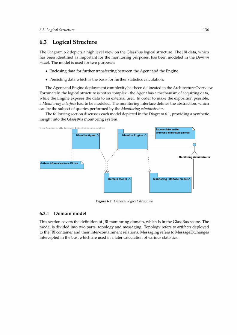
6.3. Logical Structure 136
6.3 Logical Structure
The Diagram 6.2 depicts a high level view on the GlassBus logical structure. The JBI data, whichhas been identified as important for the monitoring purposes, has been modeled in the Domainmodel. The model is used for two purposes:
• Enclosing data for further transferring between the Agent and the Engine.
• Persisting data which is the basis for further statistics calculation.
The Agent and Engine deployment complexity has been delineated in the Architecture Overview.Fortunately, the logical structure is not so complex - the Agent has a mechanism of acquiring data,while the Engine exposes the data to an external user. In order to make the exposition possible,a Monitoring interface had to be modeled. The monitoring interface defines the abstraction, whichcan be the subject of queries performed by the Monitoring administrator.
The following section discusses each model depicted in the Diagram 6.1, providing a syntheticinsight into the GlassBus monitoring system.
Figure 6.2: General logical structure
6.3.1 Domain model
This section covers the definition of JBI monitoring domain, which is in the GlassBus scope. Themodel is divided into two parts: topology and messaging. Topology refers to artifacts deployedto the JBI container and their inter-containment relations. Messaging refers to MessageExchangesintercepted in the bus, which are used in a later calculation of various statistics.
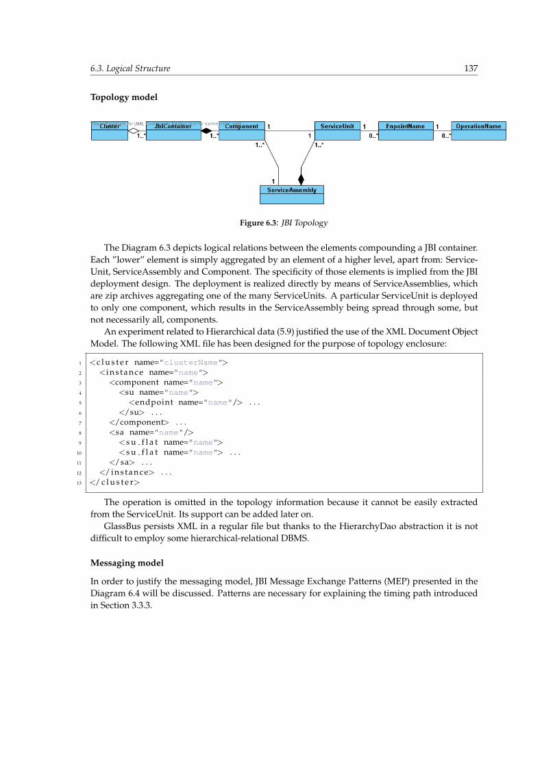
6.3. Logical Structure 137
Topology model
Figure 6.3: JBI Topology
The Diagram 6.3 depicts logical relations between the elements compounding a JBI container.Each ”lower” element is simply aggregated by an element of a higher level, apart from: Service-Unit, ServiceAssembly and Component. The specificity of those elements is implied from the JBIdeployment design. The deployment is realized directly by means of ServiceAssemblies, whichare zip archives aggregating one of the many ServiceUnits. A particular ServiceUnit is deployedto only one component, which results in the ServiceAssembly being spread through some, butnot necessarily all, components.
An experiment related to Hierarchical data (5.9) justified the use of the XML Document ObjectModel. The following XML file has been designed for the purpose of topology enclosure:
1 <c l u s t e r name="clusterName">2 <i n s t a n c e name="name">3 <component name="name">4 <su name="name">5 <endpoint name="name"/> . . .6 </su> . . .7 </component> . . .8 <sa name="name"/>9 <s u f l a t name="name">
10 <s u f l a t name="name"> . . .11 </sa> . . .12 </ i n s t a n c e> . . .13 </ c l u s t e r>
The operation is omitted in the topology information because it cannot be easily extractedfrom the ServiceUnit. Its support can be added later on.
GlassBus persists XML in a regular file but thanks to the HierarchyDao abstraction it is notdifficult to employ some hierarchical-relational DBMS.
Messaging model
In order to justify the messaging model, JBI Message Exchange Patterns (MEP) presented in theDiagram 6.4 will be discussed. Patterns are necessary for explaining the timing path introducedin Section 3.3.3.
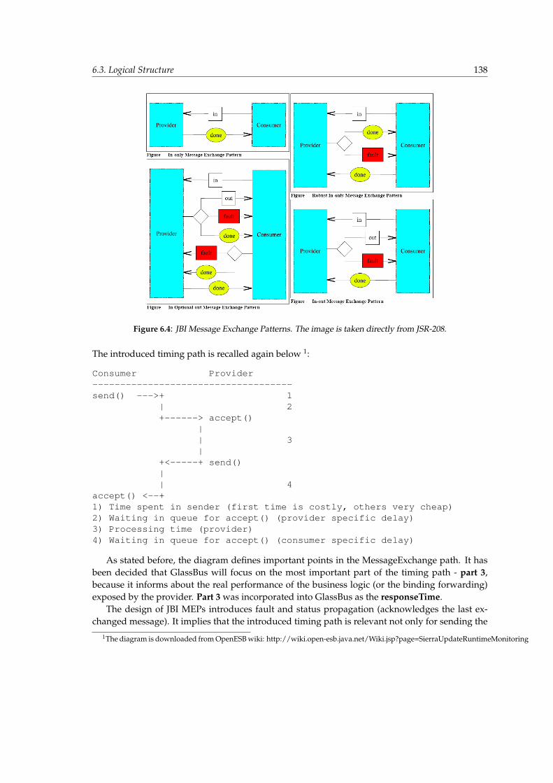
6.3. Logical Structure 138
Figure 6.4: JBI Message Exchange Patterns. The image is taken directly from JSR-208.
The introduced timing path is recalled again below 1:
Consumer Provider------------------------------------send() --->+ 1
| 2+------> accept()
|| 3|
+<-----+ send()|| 4
accept() <--+1) Time spent in sender (first time is costly, others very cheap)2) Waiting in queue for accept() (provider specific delay)3) Processing time (provider)4) Waiting in queue for accept() (consumer specific delay)
As stated before, the diagram defines important points in the MessageExchange path. It hasbeen decided that GlassBus will focus on the most important part of the timing path - part 3,because it informs about the real performance of the business logic (or the binding forwarding)exposed by the provider. Part 3 was incorporated into GlassBus as the responseTime.
The design of JBI MEPs introduces fault and status propagation (acknowledges the last ex-changed message). It implies that the introduced timing path is relevant not only for sending the
1The diagram is downloaded from OpenESB wiki: http://wiki.open-esb.java.net/Wiki.jsp?page=SierraUpdateRuntimeMonitoring
6.3. Logical Structure 139
response by provider, but also in the following cases:
• provider sending the response or fault — providersResponseTime (pRT);
• provider sending the status — providersStatusTime (pST);
• consumer sending the status — consumersStatusTime (cST);
• consumer sending the fault — consumersResponseTime (cRT);
All the above-listed time measurements are constantly related to part 3 of the timing path pre-sented earlier. Measurements start along with the invocation of the accept method and finishwhen the send method is invoked, giving the estimation of processing a particular logic: responsetime (consumer or provider), status time (consumer or provider).
The details of MEPs presented in 6.4 allow to conclude the relation between a particular MEPand possible timing paths - it is depicted in Table 6.1.
Table 6.1: Timing path - MEP relationsInOnly Robust InOnly InOut InOptionalOutpST pST pRT, cST pST
pRT, cST pRT, cSTpRT, cRT, pST
The table has multiple lines because some MEPs have several possibilities of flows (for a com-plete understanding of MEPs please refer to Section 5.4.2 of the JBI specification [2]). GlassBusmeasures every described timing, thus allowing for a complete analysis of each Message Ex-change Pattern.
Besides part 3 of the timing path, GlassBus measures the cumulative time of part 2 and 4,which are called timeInNMR. This parameter is accumulated through all the timing paths ofa particular MEP. Part 1 is out of the GlassBus’s scope because the design of the interceptorspresented in Section 5.4 does not allow to measure the time spent in the sender.
Having discussed the timing aspects, a class diagram of the messaging model is introduced inFigure 6.5. It encloses information related to the primary JBI messaging entity - Exchange, whichis the only information used for the statistics calculation. The Exchange encompasses:
• Type of MEP;
• ExchangeTargets which uniquely define the consumer and provider of an exchange. Glass-Bus permits simplification by assuming that Operations, Endpoints, ServiceUnits, Service-Assemblies and components have unique names in the scope of one JBI instance. Therefore,the name of the instance and the endpoint is sufficient for uniqueness. Operation is an op-tional endpoint compound (but alone is also unique) - its enclosure enhances precision ofmonitoring and allows to introduce ME SUB FLOW PATTERN (introduced in Section 4.4).Providing Instance and Endpoint (optionally operation) seems to be sufficient, but unfortu-nately sometimes the consumer’s endpoint cannot be acquired - it is a common case whenthe endpoint is the starting point of a JBI transaction. The consumer’s endpoint cannot bedirectly retrieved from the JBI pointcuts - it is acquired through the context provided by

6.3. Logical Structure 140
correlation heuristics. It is the reason for introducing fallbackComponentName, which canalways be supplied in case the consumer’s Endpoint is impossible to acquire;
• ExchangeStatus providing JBI’s DONE, ERROR and specific to GlassBus INTERRUPTEDwhich is set in case of MessageExchange being interrupted by some JBIException.
• ExchangeTimePath which encloses the timing explained earlier. It is associated with 2 to4 TimeIntervals (a pair of beginning and ending timestamps). Interval of the exchange’swhole timing is always provided. The remaining timings depend on a particular MEP andits messaging course type. As presented in Table 6.1, the number of these partial timingscan fluctuate between 1 and 3.
The GlassBus Endpoint terminology always refers to the ServiceEndpoint from the JBI speci-fication. To make matters simple, the Endpoint appearing in GlassBus is a regular string whichwas built by a concatenation of the ServiceEndpoint’s serviceName and endpointName.
Figure 6.5: GlassBus Dao
The Exchange is designed at an abstraction level, but the GlassBus persistence realization al-lowed to use it directly for defining the JPA Entity Beans. It resulted in a straightforward solutionof sending to GlassBus-Engine, messaging information (acquired by the interceptors) already en-closed in the Entity Beans defined by the model. The process of tracing all details of the Exchangeis presented in the next three sections.
6.3.2 GlassBus Agent
The GlassBus Agent’s essential role is to intercept events in the JBI container, which is conductedby means of the JBI pointcuts (cf. 5.4), as well as to send them to the Engine. The Agent’s classdiagram presented in Figure 6.6 will be used to explain the structure and functional blocks whichallow for providing these roles.

6.3. Logical Structure 141
Figure 6.6: GlassBus Agent
The bottom part of the diagram refers to classes related to acquiring information. There arefour aspects which crosscut JBI. Two JBITopology* aspects are related to the bus’s topology change.The specificity of the topology events allows to forward them directly to the Engine without anyadditional processing. As soon as one of the aspects intercepts an event, a method on TopologyLis-tenerMBean is invoked and the event is propagated to the Engine through a JMX over JMS layer(cf. Architecture overview).
An aspect related to messaging interception - JBIMessagingInterceptor has not been designed toforward directly messaging events. GlassBus Agent is equipped with the intelligence of buffer-ing messaging events and performing a send-out to the Engine while all information is beingacquired. In order to perform a send-out to the Engine, the information defined in the Messagingmodel has to be combined. It includes: correlationId, timeInNMR, providersFault, consumers-Fault, error, jbiException, sent and receivedRequests, sent and receivedReplies, the consumer’sand provider’s exchangeTarget. The first attribute - correlationId - is provided by means of anXML or Thread heuristic (refexp:correlation). Each intercepted exchange of ME is passed to theMessagingProcessor, which tries to incrementally gather the required attributes. The processorchooses one of the heuristics (on the basis of results) and saves partial attributes in propertiesof the MessageExchange. The attributes are accumulated in properties until the final event of aparticular MEP, where all information is gathered, is enclosed in GlassBus’s Exchange and sent tothe Engine by means of JmsSender. The consumer’s exchangeTarget is extracted by the heuristics

6.3. Logical Structure 142
but, as mentioned in the previous section, it cannot be always determined - sometimes a fallbackto the consumer’s component name is performed.
The Agent’s intelligence was implemented on the basis of the JBI’s Message Exchange Patternpresented in the previous section. The Agent knows exactly what messages are employed ineach pattern, the relations between MEPs and all timings - that knowledge is embedded into theMessagingProcessor.
The Agent uses JmsSender for the purpose of the JMS’s connection to server. The JMX overJMS communication is leveraged by other MBeans: TopologyListenerMBean, GlassBusEngineReg-isterMBean and GlassBusAgentControlMBean. The first two are part of the Engine’s code and areonly exposed to the Agent. The latter MBean is exposed by the Agent itself and serves the Enginewith the functionalities of management and accessibility checking (it is presented in Listing A.11).
The GlassBus Agent cannot be classified as a regular component of JBI - Binding Componentor Service Engine. The Agent has the ability to crosscut various JBI entities including Deliv-eryChannels of all the bus’s components. Such capability exceeds those assigned by JSR-208 to SEand BC. The GlassBus Agent should be perceived as a functional building block which integratestightly with the container’s environment and allows for acquiring the necessary monitoring in-formation (details of mechanism are described in Sections 5.3 and 5.4).
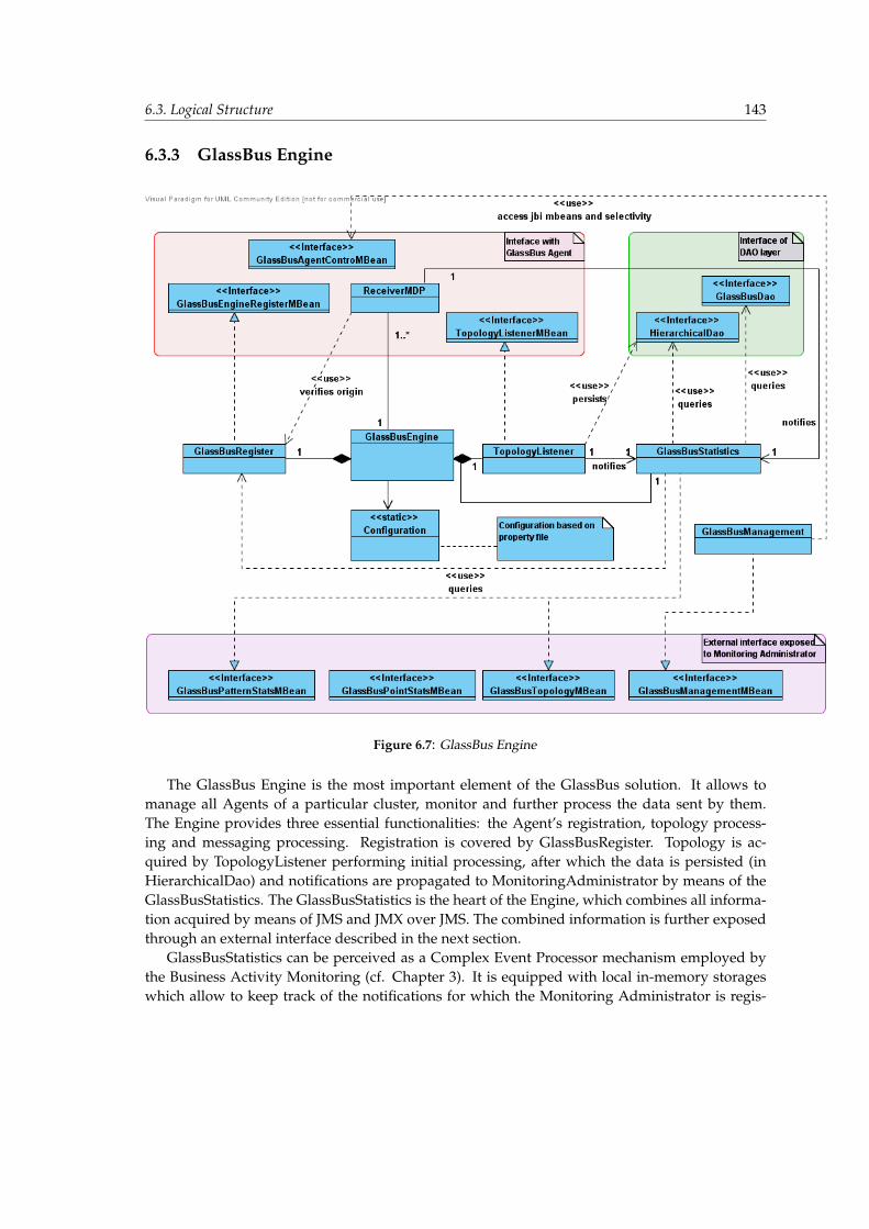
6.3. Logical Structure 143
6.3.3 GlassBus Engine
Figure 6.7: GlassBus Engine
The GlassBus Engine is the most important element of the GlassBus solution. It allows tomanage all Agents of a particular cluster, monitor and further process the data sent by them.The Engine provides three essential functionalities: the Agent’s registration, topology process-ing and messaging processing. Registration is covered by GlassBusRegister. Topology is ac-quired by TopologyListener performing initial processing, after which the data is persisted (inHierarchicalDao) and notifications are propagated to MonitoringAdministrator by means of theGlassBusStatistics. The GlassBusStatistics is the heart of the Engine, which combines all informa-tion acquired by means of JMS and JMX over JMS. The combined information is further exposedthrough an external interface described in the next section.
GlassBusStatistics can be perceived as a Complex Event Processor mechanism employed bythe Business Activity Monitoring (cf. Chapter 3). It is equipped with local in-memory storageswhich allow to keep track of the notifications for which the Monitoring Administrator is regis-

6.3. Logical Structure 144
tered. The GlassBusStatistics combines all events and decides which of them have to be translatedto some external notifications and which change the state of its intermediate storages. The En-gine’s management functionalities are provided by the GlassBusManagementMBean, which canbe used by the Monitoring Administrator to manage not only the Engine, but the entire GlassBusinfrastructure. The detailed Engine’s logic is presented in Invocation Flows Section.
6.3.4 External interface model
The model of external interface is the GlassBus’s final element, which encloses all monitoringparameters and statistics available to the Monitoring administrator. Analogically to the domainmodel, the external interface has also been divided into messaging and topology part. The mes-saging part is further divided into an interface related to:
• Pattern messaging - related to ME FLOW PATTERN, ME TRANS PATTERN etc. (theseconcepts have been introduced in Section 4.4);
• Point Messaging - related to regular JBI elements: Endpoints, Components etc.
It has already been decided in Section 5.11 that the interface is exposed through JMX MBeans.Logical parts of external interfaces have been mapped to MBeans in the following way:
• Topology — GlassBusTopologyMBean;
• Point messaging — GlassBusPointStatsMBean;
• Pattern messaging — GlassBusPatternStatsMBean.
Topology
GlassBus encloses topology in the hierarchical XML DOM model (cf. the Domain Model in Section6.3.1). It has been decided that in order to simplify the interface, the topology will be accessiblethrough an XML file presented earlier. Various topology elements can be queried by the MBeantopology:
1 public interface GlassBusTopologyMBean {2 String getTopologyCluster (boolean recursive ) ;3 String getTopologyInstance (List<String> instanceNames ,boolean recursive ) ;4 String getTopologyComponent (List<String> componenteNames ,String instanceName ,
boolean recursive ) ;5 String getTopologyServiceAssembly (List<String> saNames ,String instanceName ,
boolean recursive ) ;6 String getTopologyServiceUnit (List<String> suNames ,String instanceName ,
boolean recursive ) ;7 void registerForClusterTopology (NotificationListener listener ,boolean
recursive ) ;8 void registerForInstanceTopology (NotificationListener listener ,9 List<String> instanceNames ,boolean recursive ) ;
10 void registerForComponentTopology (NotificationListener listener ,11 List<String> componenteNames , String instanceName ,boolean recursive ) ;12 void registerForSATopology (NotificationListener listener ,13 List<String> saNames , String instanceName ,boolean recursive ) ;
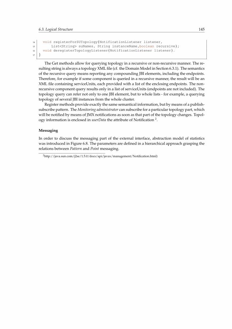
6.3. Logical Structure 145
14 void registerForSUTopology (NotificationListener listener ,15 List<String> suNames , String instanceName ,boolean recursive ) ;16 void deregisterTopologyListener (NotificationListener listener ) .17 }
The Get methods allow for querying topology in a recursive or non-recursive manner. The re-sulting string is always a topology XML file (cf. the Domain Model in Section 6.3.1). The semanticsof the recursive query means reporting any compounding JBI elements, including the endpoints.Therefore, for example if some component is queried in a recursive manner, the result will be anXML file containing serviceUnits, each provided with a list of the enclosing endpoints. The non-recursive component query results only in a list of serviceUnits (endpoints are not included). Thetopology query can refer not only to one JBI element, but to whole lists - for example, a queryingtopology of several JBI instances from the whole cluster.
Register methods provide exactly the same semantical information, but by means of a publish-subscribe pattern. The Monitoring administrator can subscribe for a particular topology part, whichwill be notified by means of JMX notifications as soon as that part of the topology changes. Topol-ogy information is enclosed in userData the attribute of Notification 2.
Messaging
In order to discuss the messaging part of the external interface, abstraction model of statisticswas introduced in Figure 6.8. The parameters are defined in a hierarchical approach grasping therelations between Pattern and Point messaging.
2http://java.sun.com/j2se/1.5.0/docs/api/javax/management/Notification.html)

6.3. Logical Structure 146
Figure 6.8: External monitoring interface
The primary entity is the ArtifactStats, which encloses statistics common to every JBI ele-ment - attribute names are meaningful, therefore further explanation is omitted. The elementsof TimeThroughput and TimeRates have been postponed for future GlassBus works, but havebeen grasped in the diagram for completeness. TimeThroughput will be related to the speedof MessageExchange traversing between various JBI elements. TimeRates will relate to: MTTF(mean-time-to-failure), MTBF (mean-time-between-failures) and MTTR (mean-time-to-react).
The ArtifactStats is primarily related to single JBI endpoint measuring requests, replies, faults,errors, etc., which appear in the context of that endpoint. GlassBus further extends such an end-point statistics allowing to measure them in other JBI elements:
• Operation — it is a compound of endpoints. Its ArtifactStats relates to messages consumedor provided by the operation.
• ServiceUnit, ServiceAssembly, Component, Instance, Cluster — these elements alwaysenclose several endpoints, which is why their ArtifactStats relates to accumulated statisticsof all endpoints in the scope of a particular entity.
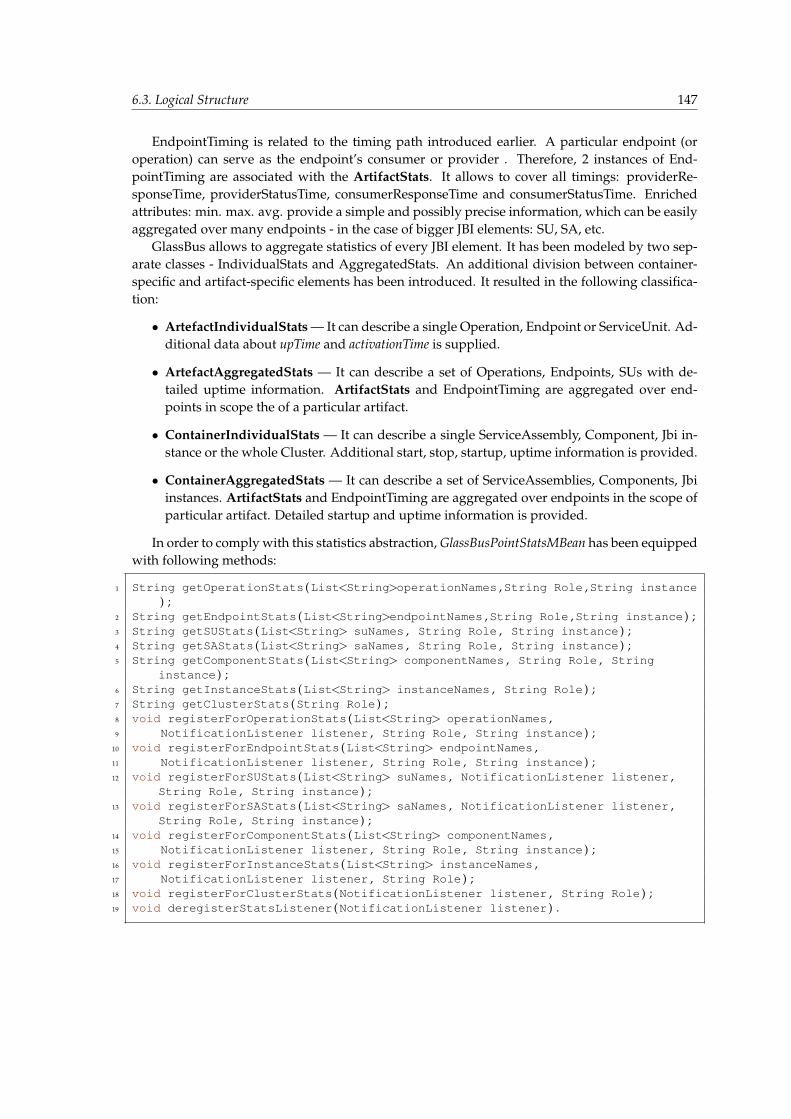
6.3. Logical Structure 147
EndpointTiming is related to the timing path introduced earlier. A particular endpoint (oroperation) can serve as the endpoint’s consumer or provider . Therefore, 2 instances of End-pointTiming are associated with the ArtifactStats. It allows to cover all timings: providerRe-sponseTime, providerStatusTime, consumerResponseTime and consumerStatusTime. Enrichedattributes: min. max. avg. provide a simple and possibly precise information, which can be easilyaggregated over many endpoints - in the case of bigger JBI elements: SU, SA, etc.
GlassBus allows to aggregate statistics of every JBI element. It has been modeled by two sep-arate classes - IndividualStats and AggregatedStats. An additional division between container-specific and artifact-specific elements has been introduced. It resulted in the following classifica-tion:
• ArtefactIndividualStats — It can describe a single Operation, Endpoint or ServiceUnit. Ad-ditional data about upTime and activationTime is supplied.
• ArtefactAggregatedStats — It can describe a set of Operations, Endpoints, SUs with de-tailed uptime information. ArtifactStats and EndpointTiming are aggregated over end-points in scope the of a particular artifact.
• ContainerIndividualStats — It can describe a single ServiceAssembly, Component, Jbi in-stance or the whole Cluster. Additional start, stop, startup, uptime information is provided.
• ContainerAggregatedStats — It can describe a set of ServiceAssemblies, Components, Jbiinstances. ArtifactStats and EndpointTiming are aggregated over endpoints in the scope ofparticular artifact. Detailed startup and uptime information is provided.
In order to comply with this statistics abstraction, GlassBusPointStatsMBean has been equippedwith following methods:
1 String getOperationStats (List<String>operationNames ,String Role ,String instance) ;
2 String getEndpointStats (List<String>endpointNames ,String Role ,String instance ) ;3 String getSUStats (List<String> suNames , String Role , String instance ) ;4 String getSAStats (List<String> saNames , String Role , String instance ) ;5 String getComponentStats (List<String> componentNames , String Role , String
instance ) ;6 String getInstanceStats (List<String> instanceNames , String Role ) ;7 String getClusterStats (String Role ) ;8 void registerForOperationStats (List<String> operationNames ,9 NotificationListener listener , String Role , String instance ) ;
10 void registerForEndpointStats (List<String> endpointNames ,11 NotificationListener listener , String Role , String instance ) ;12 void registerForSUStats (List<String> suNames , NotificationListener listener ,
String Role , String instance ) ;13 void registerForSAStats (List<String> saNames , NotificationListener listener ,
String Role , String instance ) ;14 void registerForComponentStats (List<String> componentNames ,15 NotificationListener listener , String Role , String instance ) ;16 void registerForInstanceStats (List<String> instanceNames ,17 NotificationListener listener , String Role ) ;18 void registerForClusterStats (NotificationListener listener , String Role ) ;19 void deregisterStatsListener (NotificationListener listener ) .

6.3. Logical Structure 148
Analogically to the case of TopologyMBean, information is available by means of regularmethod calls and by means of JMX Notifications. Another analogy with the topology is thatmethod’s result (sent as userData of Notification) provides statistics also through an XML file. Asample result is provided in Listing (A.12). All methods can be invoked with Role an argumentthat can restrict the scope to particular consuming or providing MessageExchanges. It allows tomeasure the performance of the business logic provided by some component. The Role argumentcan have values of: ”CONSUMER”, ”PROVIDER” or null, which includes both roles.
Pattern Messaging
GlassBus introduced new terminology of Flow and Trans Pattern (detailed information is pro-vided in Section 4.4: ME FLOW PATTERN, ME TRANS PATTERN). The primary entity of pat-tern messaging is ME SUB FLOW PATTERN Stats, which defines exchanges between two oper-ations of some endpoints. It introduces only one new attribute - totalInvocations (which informsabout the total amount of consumer-provider messages invocations), but it also changes the se-mantics of ArtifactStats and EndpointTiming. In this context they relate only to message ex-changes between ME SUB FLOW PATTERN’s consuming and providing operations. It is a dif-ferent situation than aggregating these two operations by means of the getOperationStats method.
ME FLOW PATTERN Stats has the same semantics as ME SUB FLOW PATTERN, but it re-lates to endpoints, not operations (cf. Section 4.4). Therefore, the diagram grasps the fact thatME FLOW PATTERN Stats can be associated with several ME SUB FLOW PATTERN Stats. ME TRANS PATTERN Statsrelates to the JBI transaction, which can be perceived as several ME SUB FLOW PATTERNs inter-connected with each other - it is the reason for the ”one to many” association. ME TRANS PATTERN Statscan be used to enclose the statistics of both: the whole business operation (BUSS TRANS PATTERNconcept from Section 4.4) and transaction (ME TRANS PATTERN).
Pattern messaging is supported by the following methods of GlassBusPatternStatsMBean:
1 String queryTrans (String partialTransactionPath ) ;2
3 String listTransInCluster ( ) ;4 String listTransStartingInInstance (String name ) ;5 String listTransStartingInComponent (String name , String instance ) ;6 String listTransStartingInSA (String name , String instance ) ;7 // a l s o provided : InSU , InEndpoint , InOperation8
9 void registerForNewTransInCluster (NotificationListener listener ) ;10 // a l s o provided : InIns tance , InComponent , InSA , InSU , InEndpoint , InOperation and
d e r e g i s t e r11
12 String listBusinessOpInCluster ( ) ;13 String listBusinessOpStartingInInstance (String name ) ;14 // a l s o provided : InComponent , InSA , InSU , InEndpoint , InOperation15
16 void registerForNewBusinessOpInCluster (NotificationListener listener ) ;17 // a l s o provided : InIns tance , InComponent , InSA , InSU , InEndpoint , InOperation and
d e r e g i s t e r18
19 String getSubFlowStats (Map<String ,String>consumerProviderOperations ,Map<String ,String>fallbackComponentConsumerProviderOperations ,String instance ) ;
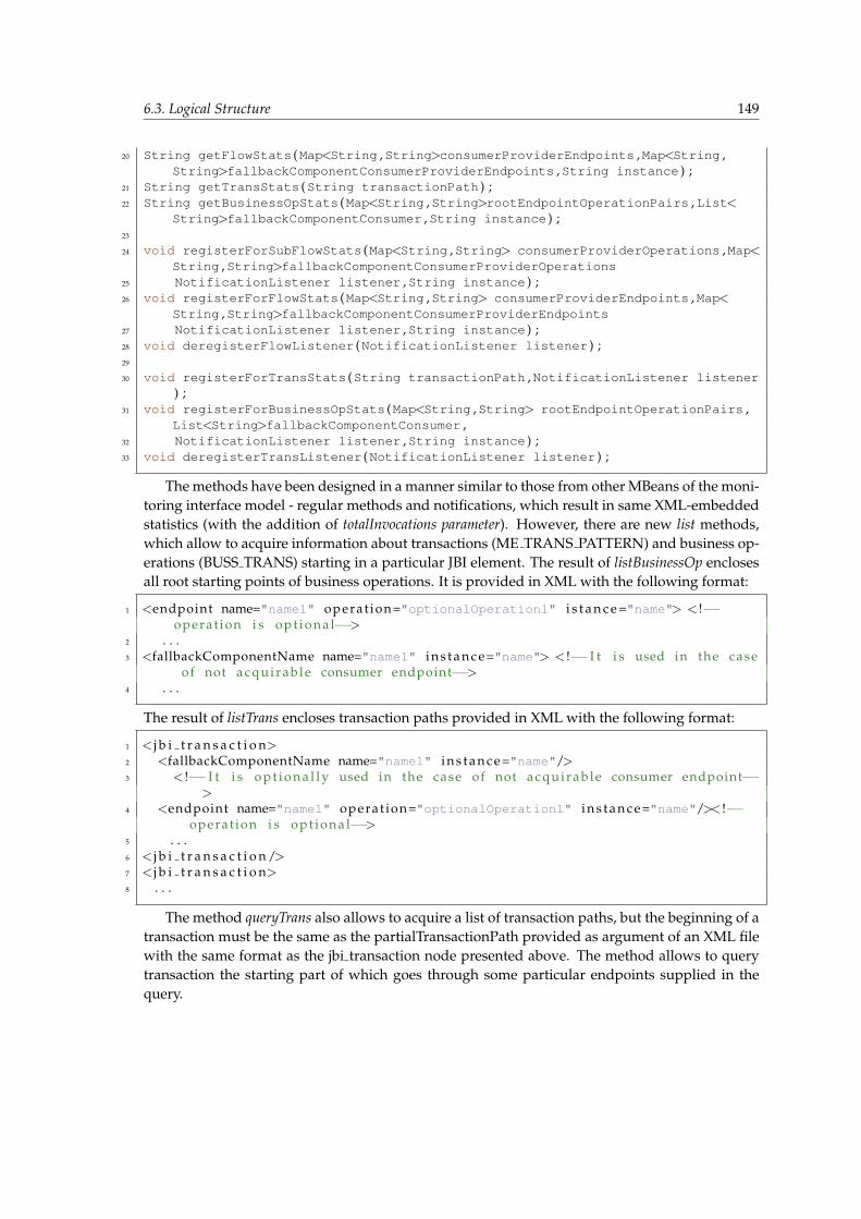
6.3. Logical Structure 149
20 String getFlowStats (Map<String ,String>consumerProviderEndpoints ,Map<String ,String>fallbackComponentConsumerProviderEndpoints ,String instance ) ;
21 String getTransStats (String transactionPath ) ;22 String getBusinessOpStats (Map<String ,String>rootEndpointOperationPairs ,List<
String>fallbackComponentConsumer ,String instance ) ;23
24 void registerForSubFlowStats (Map<String ,String> consumerProviderOperations ,Map<String ,String>fallbackComponentConsumerProviderOperations
25 NotificationListener listener ,String instance ) ;26 void registerForFlowStats (Map<String ,String> consumerProviderEndpoints ,Map<
String ,String>fallbackComponentConsumerProviderEndpoints27 NotificationListener listener ,String instance ) ;28 void deregisterFlowListener (NotificationListener listener ) ;29
30 void registerForTransStats (String transactionPath ,NotificationListener listener) ;
31 void registerForBusinessOpStats (Map<String ,String> rootEndpointOperationPairs ,List<String>fallbackComponentConsumer ,
32 NotificationListener listener ,String instance ) ;33 void deregisterTransListener (NotificationListener listener ) ;
The methods have been designed in a manner similar to those from other MBeans of the moni-toring interface model - regular methods and notifications, which result in same XML-embeddedstatistics (with the addition of totalInvocations parameter). However, there are new list methods,which allow to acquire information about transactions (ME TRANS PATTERN) and business op-erations (BUSS TRANS) starting in a particular JBI element. The result of listBusinessOp enclosesall root starting points of business operations. It is provided in XML with the following format:
1 <endpoint name="name1" operat ion="optionalOperation1" i s t a n c e ="name"> < !−−operat ion i s opt iona l−−>
2 . . .3 <fallbackComponentName name="name1" i n s t a n c e ="name"> < !−−I t i s used in the case
of not a c qu i r a b l e consumer endpoint−−>4 . . .
The result of listTrans encloses transaction paths provided in XML with the following format:
1 < j b i t r a n s a c t i o n>2 <fallbackComponentName name="name1" i n s t a n c e ="name"/>3 < !−−I t i s o p t i o n a l l y used in the case of not a c q ui r a b le consumer endpoint−−
>4 <endpoint name="name1" operat ion="optionalOperation1" i n s t a n c e ="name"/>< !−−
operat ion i s opt iona l−−>5 . . .6 < j b i t r a n s a c t i o n />7 < j b i t r a n s a c t i o n>8 . . .
The method queryTrans also allows to acquire a list of transaction paths, but the beginning of atransaction must be the same as the partialTransactionPath provided as argument of an XML filewith the same format as the jbi transaction node presented above. The method allows to querytransaction the starting part of which goes through some particular endpoints supplied in thequery.
6.3. Logical Structure 150
The methods registerForNew* provide a listener notification in case of new transactions or busi-ness operations appearing in a particular cluster scope.
The methods getSubFlowStats and getFlowStats (also their notification equivalents) allow toacquire statistics about particular ME SUB FLOW PATTERNs and ME FLOW PATTERNs. Con-sumer of ME FLOW PATTERN can be also specified by means of the componentFallback name(used when the consumer’s endpoint is not acquirable), but it is optional. Method’s Map ar-guments allow to supply multiple values and therefore conduct an aggregation of the relatedME SUB FLOW PATTERNs or ME FLOW PATTERNs.
The getBusinessOpStats method (and its notification equivalent) allows to query statistics ofwhole business operations. The method provides the possibility of aggregation (thanks to Mapand List arguments) and the option of supplying the consumer by means of the component’sname.
The only method not equipped with aggregation is getTransStats (along with its notificationequivalent), which allows to acquire statistics of a particular transaction (ME TRANS PATTERN).Transactions can only be aggregated by means of business operations that enclose them. Un-fortunately, a transaction has to be specified through all compounding endpoints (and possiblythrough fallbackContainerName at the beginning) enclosed in an XML argument of the sameformat as the jbi transaction node presented above (reference to the schema).
6.3.5 Management and selectivity model
As it has been delineated before, GlassBus is not only the Monitoring solution. Its architectureallowed for providing a wide range of management features. Management, analogically to mon-itoring, is realized at several levels providing flexibility of adjusting GlassBus to particular needsand tuning the selectivity of gathering monitoring information. The problem with managementcomes from the distributed GlassBus architecture. It is easy to imagine a federation of fifty JBIcontainers instrumented with GlassBus. The management of such a widespread cluster is diffi-cult not only in terms of adjusting the GlassBus Agent mechanism, but also in terms of managingthe containers themselves. The GlassBus management architecture solves both problems.
GlassBus Agents can be managed in two ways:
• by JMX management interface;
• by configuration files.
Both mechanisms allow to control similar elements, but JMX management is equipped withbroader functionalities, which is the reason for discussing it in the first place. The discussionof configuration is presented in one of next sections (6.5).
In order to provide selectivity of the information gathering mechanism, several levels of dataacquiring have been introduced:
• TOPOLOGY — only the information about the bus topology is gathered by the Agent andforwarded to the Engine. The topology is additionally divided into inner levels of selectiv-ity:
– COMPONENT — only information about components is acquired (employing JBITopol-ogyComponentInterceptor);
6.3. Logical Structure 151
– SERVICE UNIT — information about components, service assemblies and serviceunits is acquired (employing JBITopologyComponentInterceptor and part of JBITopol-ogySUInterceptor);
– ENDPOINT — information at all levels including endpoints and operations is ac-quired (employing both JBITopologyComponentInterceptor and JBITopologySUInter-ceptor);
• MESSAGING BASIC — the topology information is enriched with messaging events, butno inter-message correlation is applied (employing all topology interceptors and JBIMes-sagingInterceptor);
• MESSAGING COMPLETE — all acquirable information is gathered, including: topology,messaging along with correlation into jbi transactions (employing all topology, messaginginterceptors and additionally correlation heuristics).
The lowest possible monitoring level is TOPOLOGY with an inner COMPONENT level.JMX management of the Agent is realized by means of GlassBusAgentControlMBean, which
is equipped with the following methods:
• getGlobalSelectivityLevel;
• getTopologySelectivityLevel;
• setGlobalSelectivityLevel;
• setTopologySelectivityLevel;
The methods allow for a flexible adjustment of the GlassBus information monitoring.Another functionality of the GlassBusAgentControlMBean is forwarding JBI MBeans, which
are defined in JSR-208. It means that a reference to those MBeans can be obtained through invo-cation of the GlassBusAgentControlMBean methods (the code is provided in Listing A.11). Thefollowing MBeans are obtainable:
• AdminServiceMBean;
• DeploymentServiceMBean;
• InstallationServiceMBean;
Thanks to the exposition of GlassBusAgentControlMBean to the Engine, all the above-listed se-lectivity levels and JBI MBeans can be managed from one central point - the GlassBus Engine.As depicted in the Engine’s class diagram (6.7), the GlassBusAgentControlMBean of each Agentis accessed by the GlassBusManagementMBean, which allows the Monitoring administrator tomanage every Agent. As it has been mentioned at the beginning of this section, such a solutioncombines the capabilities of managing not only GlassBus Agent, but also the JBI Container itself.The GlassBus Engine can be used to install new components or deploy new service assemblieson distant JBI containers (for the functionalities of JBI MBean pleas refer to the JBI Status Quo 3.3provided earlier).

6.3. Logical Structure 152
Aspect weaving adjustment
GlassBus installer instrumentation of the Agent is accompanied with the incorporation of all as-pects into the JBI container. It implies that in the course of the container initialization all aspectsare woven into the bus’s code. Therefore, setting a lower selectivity cannot disable pointcuts al-ready woven. Instead, each pointcut is equipped with checking the selectivity level and on itsbasis performs a logic or abandons it. Such a solution results in the minimal performance im-pact in the case of lower selectivity levels. It has been decided that this mechanism is sufficientfor the purpose of performance impact minimization, however the user of GlassBus may still beconcerned about disabling weaving of the unwanted aspects. It can be simply achieved by meansof a modification aop.xml file (A.8) which is embedded in the following jar artifacts: glassbus-agent-smix and glassbus-agent-openesb. In the course of the modification modification, aspectsdependencies have to be preserved: the heuristics rely on messaging, the messaging relies ontopology.
6.3.6 Invocation flows
This section is devoted to discussing end-to-end flows of the three main GlassBus functionalities:registration, messaging and topology propagation. Every functionality is delineated in a separateUML activity diagram. The diagrams allow for a clear expression of dependencies between thelogical structure elements and their interactions.

6.3. Logical Structure 153
Agent registration
Figure 6.9: The Agent in the Engine registration sequence diagram
Agent registration, depicted in Figure 6.9 is crucial for the whole GlassBus operation. Nei-ther messaging nor topology propagation can be realized without a successful registration. Inorder to join the monitoring domain of a particular Engine, the Agent needs to know its namea priori. The default name of the Engine is ”JbiMonitoringEngine”, but it can be adjusted in thecomponent’s properties files (presented in Section 6.5). The Agent invokes registration in theGlassBusEngineRegisterMBean interface. The Engine verifies the Agent’s accessibility by meansof GlassBusAgentControlMBean. Both interfaces are provided by Lingo’s JMX over JMS andare not released during the further Engine’s and Agent’s lifetime. They are used for a constantaccessibility verification allowing for instant identification of problems with the Agent-Enginecommunication.
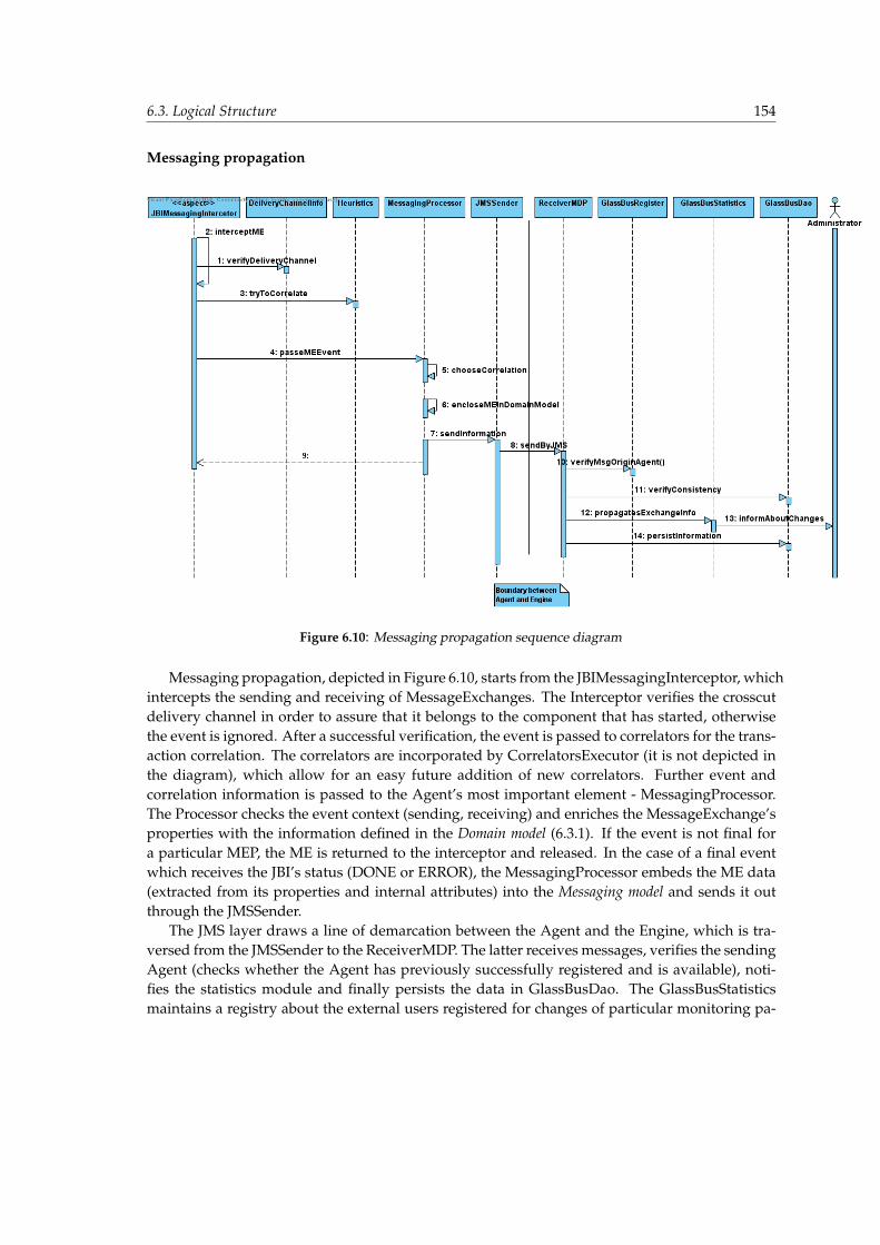
6.3. Logical Structure 154
Messaging propagation
Figure 6.10: Messaging propagation sequence diagram
Messaging propagation, depicted in Figure 6.10, starts from the JBIMessagingInterceptor, whichintercepts the sending and receiving of MessageExchanges. The Interceptor verifies the crosscutdelivery channel in order to assure that it belongs to the component that has started, otherwisethe event is ignored. After a successful verification, the event is passed to correlators for the trans-action correlation. The correlators are incorporated by CorrelatorsExecutor (it is not depicted inthe diagram), which allow for an easy future addition of new correlators. Further event andcorrelation information is passed to the Agent’s most important element - MessagingProcessor.The Processor checks the event context (sending, receiving) and enriches the MessageExchange’sproperties with the information defined in the Domain model (6.3.1). If the event is not final fora particular MEP, the ME is returned to the interceptor and released. In the case of a final eventwhich receives the JBI’s status (DONE or ERROR), the MessagingProcessor embeds the ME data(extracted from its properties and internal attributes) into the Messaging model and sends it outthrough the JMSSender.
The JMS layer draws a line of demarcation between the Agent and the Engine, which is tra-versed from the JMSSender to the ReceiverMDP. The latter receives messages, verifies the sendingAgent (checks whether the Agent has previously successfully registered and is available), noti-fies the statistics module and finally persists the data in GlassBusDao. The GlassBusStatisticsmaintains a registry about the external users registered for changes of particular monitoring pa-

6.4. Physical Structure 155
rameters and informs the users when it is appropriate.
Topology propagation
Figure 6.11: Topology propagation sequence diagram
The topology propagation, depicted in Figure 6.11, is less complicated than the messagingpropagation. Only six main entities are involved - the three that are left are of the Agent and therest belong to the Engine. The diagram captures the fact that the interception of the componentand ServiceUnit events are not related - they can even take place concurrently. The JBITopolo-gyComponentInterceptor updates the register of the DeliveryChannelInfo (containing bindingsbetween the components and their delivery channels), which has previously been presented inMessaging propagation the diagram. The rest of the flow is the same for both the JBITopology-ComponentInterceptor and the JBITopologySUInterceptor. The border between the Agent andthe Engine is traversed by means of the JMX over JMS layer - the methods of TopologyListen-erMBean allow to propagate the intercepted topology changes. The TopologyListener performsfurther verification, notification of statistics module and finally persists the information in Hierar-chicalDao. By analogy to the messaging propagation, the GlassBusStatistics informs the externalusers when it is appropriate.
6.4 Physical Structure
It has been decided that Maven [43] will be used for the purpose of the GlassBus implementationstructuring and building. Its hierarchical model allowed for a flexible arrangement of the Glass-Bus artifacts. Thhe Glassbus’s physical structure has been delineated in Figure 6.12 by means of aUML package diagram. The diagram provides a namespace of each artifact, which can be usefulfor the purpose of logging configuration.
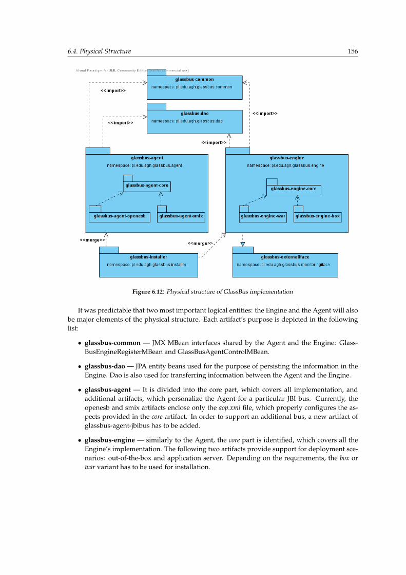
6.4. Physical Structure 156
Figure 6.12: Physical structure of GlassBus implementation
It was predictable that two most important logical entities: the Engine and the Agent will alsobe major elements of the physical structure. Each artifact’s purpose is depicted in the followinglist:
• glassbus-common — JMX MBean interfaces shared by the Agent and the Engine: Glass-BusEngineRegisterMBean and GlassBusAgentControlMBean.
• glassbus-dao — JPA entity beans used for the purpose of persisting the information in theEngine. Dao is also used for transferring information between the Agent and the Engine.
• glassbus-agent — It is divided into the core part, which covers all implementation, andadditional artifacts, which personalize the Agent for a particular JBI bus. Currently, theopenesb and smix artifacts enclose only the aop.xml file, which properly configures the as-pects provided in the core artifact. In order to support an additional bus, a new artifact ofglassbus-agent-jbibus has to be added.
• glassbus-engine — similarly to the Agent, the core part is identified, which covers all theEngine’s implementation. The following two artifacts provide support for deployment sce-narios: out-of-the-box and application server. Depending on the requirements, the box orwar variant has to be used for installation.
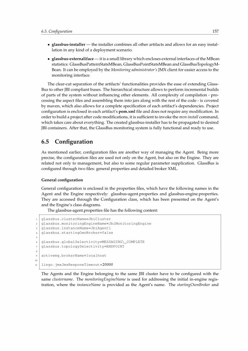
6.5. Configuration 157
• glassbus-installer — the installer combines all other artifacts and allows for an easy instal-lation in any kind of a deployment scenario.
• glassbus-externaliface — it is a small library which encloses external interfaces of the MBeanstatistics: GlassBusPatternStatsMBean, GlassBusPointStatsMBean and GlassBusTopologyM-Bean. It can be employed by the Monitoring administrator’s JMX client for easier access to themonitoring interface.
The clear-cut separation of the artifacts’ functionalities provides the ease of extending Glass-Bus to other JBI compliant buses. The hierarchical structure allows to perform incremental buildsof parts of the system without influencing other elements. All complexity of compilation - pro-cessing the aspect files and assembling them into jars along with the rest of the code - is coveredby maven, which also allows for a complete specification of each artifact’s dependencies. Projectconfiguration is enclosed in each artifact’s pom.xml file and does not require any modification. Inorder to build a project after code modifications, it is sufficient to invoke the mvn install command,which takes care about everything. The created glassbus-installer has to be propagated to desiredJBI containers. After that, the GlassBus monitoring system is fully functional and ready to use.
6.5 Configuration
As mentioned earlier, configuration files are another way of managing the Agent. Being moreprecise, the configuration files are used not only on the Agent, but also on the Engine. They arerelated not only to management, but also to some regular parameter supplication. GlassBus isconfigured through two files: general properties and detailed broker XML.
General configuration
General configuration is enclosed in the properties files, which have the following names in theAgent and the Engine respectively: glassbus-agent.properties and glassbus-engine.properties.They are accessed through the Configuration class, which has been presented on the Agent’sand the Engine’s class diagrams.
The glassbus-agent.properties file has the following content:
1 glassbus .clusterName=JbiCluster2 glassbus .monitoringEngineName=JbiMonitoringEngine3 glassbus .instanceName=JbiAgent14 glassbus .startingOwnBroker=false5
6 glassbus .globalSelectivity=MESSAGING\_COMPLETE7 glassbus .topologySelectivity=ENDPOINT8
9 activemq .brokerName=localhost10
11 lingo .jmxJmsResponeTimeout=20000
The Agents and the Engine belonging to the same JBI cluster have to be configured with thesame clustername. The monitoringEngineName is used for addressing the initial in-engine regis-tration, where the instanceName is provided as the Agent’s name. The startingOwnBroker and
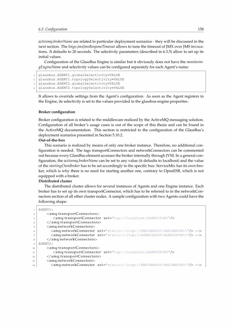
6.5. Configuration 158
activemq.brokerName are related to particular deployment scenarios - they will be discussed in thenext section. The lingo.jmxJmsResponeTimeout allows to tune the timeout of JMX over JMS invoca-tions. It defaults to 20 seconds. The selectivity parameters (described in 6.3.5) allow to set up itsinitial values.
Configuration of the GlassBus Engine is similar but it obviously does not have the monitorin-gEngineName and selectivity values can be configured separately for each Agent’s name:
1 glassbus .AGENT1 .globalSelectivity=VALUE2 glassbus .AGENT1 .topologySelectivity=VALUE3 glassbus .AGENT2 .globalSelectivity=VALUE4 glassbus .AGENT2 .topologySelectivity=VALUE
It allows to override settings from the Agent’s configuration. As soon as the Agent registers inthe Engine, its selectivity is set to the values provided in the glassbus-engine.properties.
Broker configuration
Broker configuration is related to the middleware realized by the ActiveMQ messaging solution.Configuration of all broker’s usage cases is out of the scope of this thesis and can be found inthe ActiveMQ documentation. This section is restricted to the configuration of the GlassBus’sdeployment scenarios presented in Section 5.10.2.Out-of-the-box
This scenario is realized by means of only one broker instance. Therefore, no additional con-figuration is needed. The tags transportConnectors and networkConnectors can be commentedout because every GlassBus element accesses the broker internally through JVM. In a general con-figuration, the activemq.brokerName can be set to any value (it defaults to localhost) and the valueof the startingOwnBroker has to be set accordingly to the specific bus: ServiceMix has its own bro-ker, which is why there is no need for starting another one, contrary to OpenESB, which is notequipped with a broker.Distributed cluster
The distributed cluster allows for several instances of Agents and one Engine instance. Eachbroker has to set up its own transportConnector, which has to be referred to in the networkCon-nectors section of all other cluster nodes. A sample configuration with two Agents could have thefollowing shape:
1 AGENT1:2 <amq:transportConnectors>3 <amq:transportConnector u r i="tcp://localhost:AGENT1PORT"/>4 </amq:transportConnectors>5 <amq:networkConnectors>6 <amq:networkConnector u r i="static://(tcp://ENGINEHOST:ENGINEPORT)"/> −−>7 <amq:networkConnector u r i="static://(tcp://AGENT2HOST:AGENT2PORT)"/> −−>8 </amq:networkConnectors>9 AGENT2:
10 <amq:transportConnectors>11 <amq:transportConnector u r i="tcp://localhost:AGENT2PORT"/>12 </amq:transportConnectors>13 <amq:networkConnectors>14 <amq:networkConnector u r i="static://(tcp://ENGINEHOST:ENGINEPORT)"/> −−>
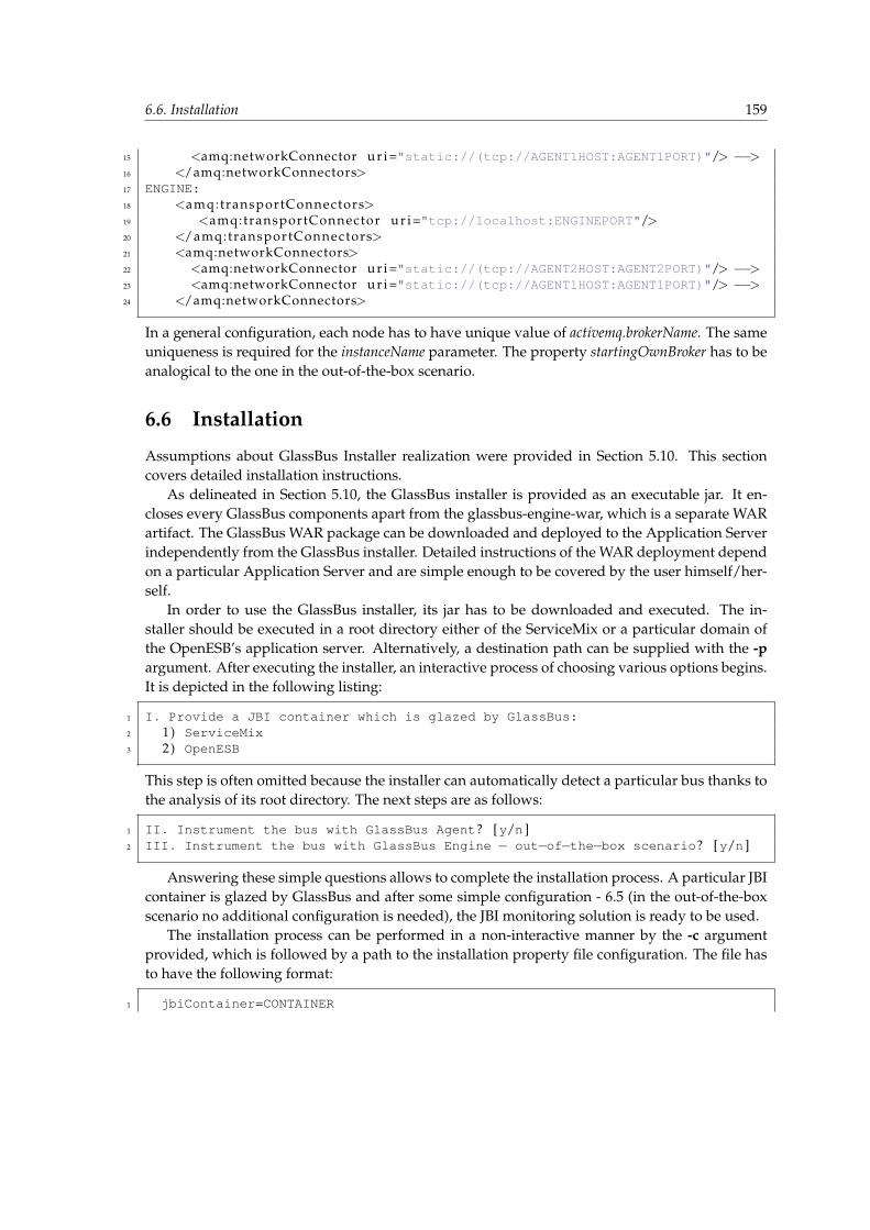
6.6. Installation 159
15 <amq:networkConnector u r i="static://(tcp://AGENT1HOST:AGENT1PORT)"/> −−>16 </amq:networkConnectors>17 ENGINE:18 <amq:transportConnectors>19 <amq:transportConnector u r i="tcp://localhost:ENGINEPORT"/>20 </amq:transportConnectors>21 <amq:networkConnectors>22 <amq:networkConnector u r i="static://(tcp://AGENT2HOST:AGENT2PORT)"/> −−>23 <amq:networkConnector u r i="static://(tcp://AGENT1HOST:AGENT1PORT)"/> −−>24 </amq:networkConnectors>
In a general configuration, each node has to have unique value of activemq.brokerName. The sameuniqueness is required for the instanceName parameter. The property startingOwnBroker has to beanalogical to the one in the out-of-the-box scenario.
6.6 Installation
Assumptions about GlassBus Installer realization were provided in Section 5.10. This sectioncovers detailed installation instructions.
As delineated in Section 5.10, the GlassBus installer is provided as an executable jar. It en-closes every GlassBus components apart from the glassbus-engine-war, which is a separate WARartifact. The GlassBus WAR package can be downloaded and deployed to the Application Serverindependently from the GlassBus installer. Detailed instructions of the WAR deployment dependon a particular Application Server and are simple enough to be covered by the user himself/her-self.
In order to use the GlassBus installer, its jar has to be downloaded and executed. The in-staller should be executed in a root directory either of the ServiceMix or a particular domain ofthe OpenESB’s application server. Alternatively, a destination path can be supplied with the -pargument. After executing the installer, an interactive process of choosing various options begins.It is depicted in the following listing:
1 I . Provide a JBI container which is glazed by GlassBus:2 1) ServiceMix3 2) OpenESB
This step is often omitted because the installer can automatically detect a particular bus thanks tothe analysis of its root directory. The next steps are as follows:
1 II . Instrument the bus with GlassBus Agent? [y/n ]2 III . Instrument the bus with GlassBus Engine − out−of−the−box scenario? [y/n ]
Answering these simple questions allows to complete the installation process. A particular JBIcontainer is glazed by GlassBus and after some simple configuration - 6.5 (in the out-of-the-boxscenario no additional configuration is needed), the JBI monitoring solution is ready to be used.
The installation process can be performed in a non-interactive manner by the -c argumentprovided, which is followed by a path to the installation property file configuration. The file hasto have the following format:
1 jbiContainer=CONTAINER

6.7. Implementation status 160
2 glassbusAgent=Yes/No3 glassbusEngine=Yes/No
It allows to perform GlassBus deployment on a large scale (big JBI clusters) in an automatedmanner.
If the installer is invoked with the -u argument, uninstallation of a particular GlassBus com-ponent can be performed. The interactive and non-interactive uninstallation process is analogicalto the installation one.
6.7 Implementation status
In the course of the work on this thesis, it turned out that creating a complete architecture forthe JBI monitoring solution is not an easy task. The contradiction between the requirement of afully JBI compliant bus and the requirement of ServiceMix and OpenESB support in terms that arebeyond the JBI scope (i.e. clustering), resulted in an architecture of a high complexity level. Thewide range of solved problems discussed in Chapter 5 provides a good complexity estimation,which is verified by the completeness of the final functionalities described in Chapter 6. Sucha GlassBus evolution resulted in restricting the implementation of a system with a productionquality. The GlassBus design presented in this thesis has been based on a complete set of Proof OfConcept [106] implementations, which allowed to verify every architectural decision.
As the fully functional implementation of GlassBus with a production quality is out of thescope of this thesis, it has been decided to provide only the research version of GlassBus. Thisversion focuses on validating both the out-of-the-box and the distributed scenarios, but not inall cases. End-to-end flow of information is provided in each case (registration, topology prop-agation, messaging propagation) but without a complete implementation of the Engine’s Glass-BusStatistics class, which comes to simple operations on the persisted data. The RCP GUI hasbeen identified as a complex feature that was not essential. The implementation of the JMX ex-ternal monitoring interface was entirely sufficient for the research, therefore a GUI has not beenprovided. It can be conceived that the research version of GlassBus is a fully functional skeletonbut not a complete production system. The skeleton solves all crucial problems in an innovativeway, leaving the regular implementation of well-known elements in scope of future GlassBus’swork.
6.8 Performance Tests
In order to validate the GlassBus solution, some performance tests have been conducted. Thecrucial issue, which has driven the architectural decisions, is the influence on the JBI container’sperformance. That was the reason for decoupling Agent instrumentation from Engine process-ing and analysis. The deep analysis of JMSSender performance and choosing high-performancemessaging middleware solution - ActiveMQ allowed to minimize the overhead on the Agent’sside. The research version of GlassBus does not provide all functionalities of the Engine’s statistics,but it is not an obstacle for performance tests which focus on the GlassBus Agent’s influence onServiceMix and OpenESB.
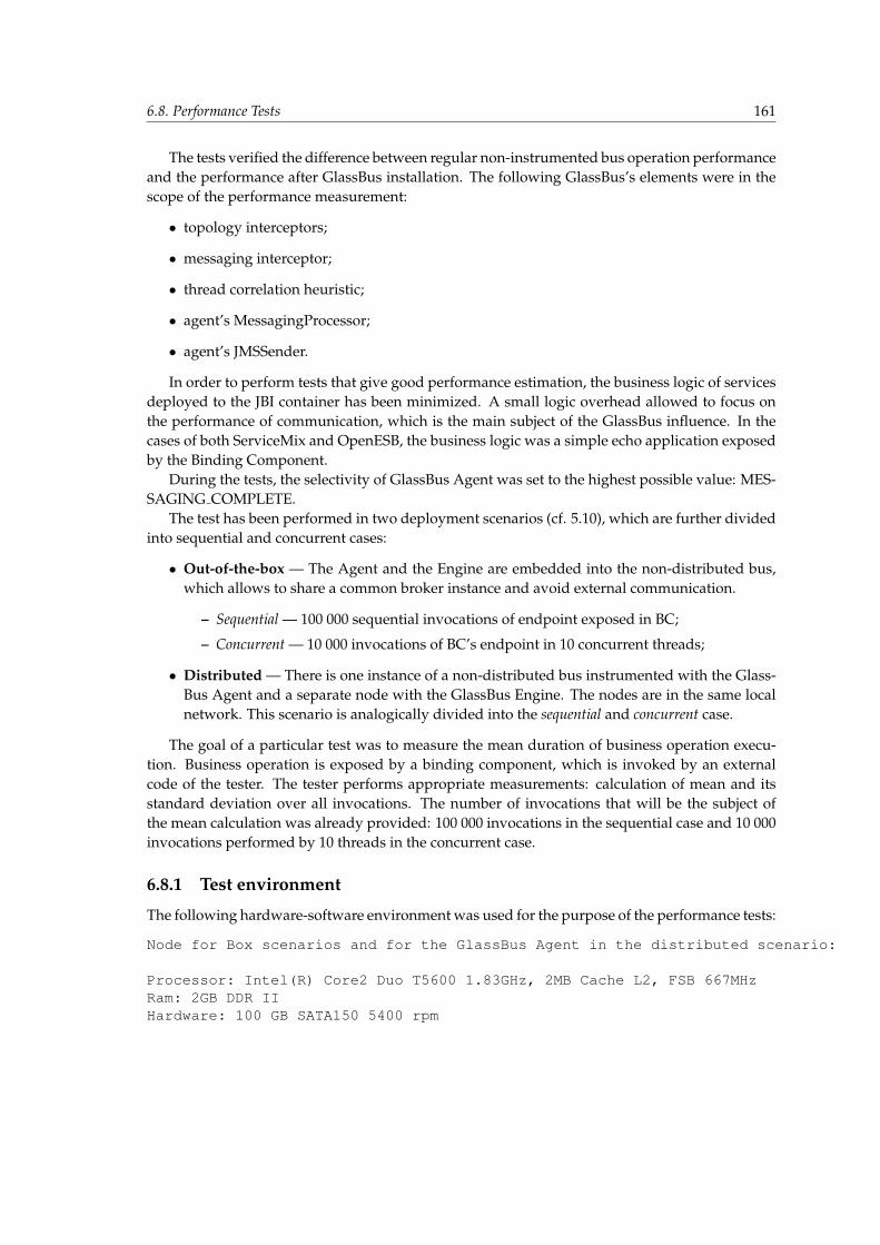
6.8. Performance Tests 161
The tests verified the difference between regular non-instrumented bus operation performanceand the performance after GlassBus installation. The following GlassBus’s elements were in thescope of the performance measurement:
• topology interceptors;
• messaging interceptor;
• thread correlation heuristic;
• agent’s MessagingProcessor;
• agent’s JMSSender.
In order to perform tests that give good performance estimation, the business logic of servicesdeployed to the JBI container has been minimized. A small logic overhead allowed to focus onthe performance of communication, which is the main subject of the GlassBus influence. In thecases of both ServiceMix and OpenESB, the business logic was a simple echo application exposedby the Binding Component.
During the tests, the selectivity of GlassBus Agent was set to the highest possible value: MES-SAGING COMPLETE.
The test has been performed in two deployment scenarios (cf. 5.10), which are further dividedinto sequential and concurrent cases:
• Out-of-the-box — The Agent and the Engine are embedded into the non-distributed bus,which allows to share a common broker instance and avoid external communication.
– Sequential — 100 000 sequential invocations of endpoint exposed in BC;
– Concurrent — 10 000 invocations of BC’s endpoint in 10 concurrent threads;
• Distributed — There is one instance of a non-distributed bus instrumented with the Glass-Bus Agent and a separate node with the GlassBus Engine. The nodes are in the same localnetwork. This scenario is analogically divided into the sequential and concurrent case.
The goal of a particular test was to measure the mean duration of business operation execu-tion. Business operation is exposed by a binding component, which is invoked by an externalcode of the tester. The tester performs appropriate measurements: calculation of mean and itsstandard deviation over all invocations. The number of invocations that will be the subject ofthe mean calculation was already provided: 100 000 invocations in the sequential case and 10 000invocations performed by 10 threads in the concurrent case.
6.8.1 Test environment
The following hardware-software environment was used for the purpose of the performance tests:
Node for Box scenarios and for the GlassBus Agent in the distributed scenario:
Processor: Intel(R) Core2 Duo T5600 1.83GHz, 2MB Cache L2, FSB 667MHzRam: 2GB DDR IIHardware: 100 GB SATA150 5400 rpm
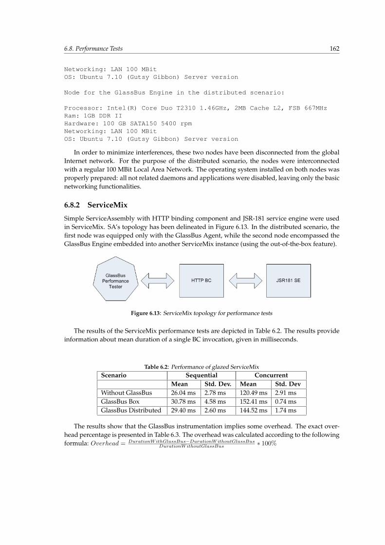
6.8. Performance Tests 162
Networking: LAN 100 MBitOS: Ubuntu 7.10 (Gutsy Gibbon) Server version
Node for the GlassBus Engine in the distributed scenario:
Processor: Intel(R) Core Duo T2310 1.46GHz, 2MB Cache L2, FSB 667MHzRam: 1GB DDR IIHardware: 100 GB SATA150 5400 rpmNetworking: LAN 100 MBitOS: Ubuntu 7.10 (Gutsy Gibbon) Server version
In order to minimize interferences, these two nodes have been disconnected from the globalInternet network. For the purpose of the distributed scenario, the nodes were interconnectedwith a regular 100 MBit Local Area Network. The operating system installed on both nodes wasproperly prepared: all not related daemons and applications were disabled, leaving only the basicnetworking functionalities.
6.8.2 ServiceMix
Simple ServiceAssembly with HTTP binding component and JSR-181 service engine were usedin ServiceMix. SA’s topology has been delineated in Figure 6.13. In the distributed scenario, thefirst node was equipped only with the GlassBus Agent, while the second node encompassed theGlassBus Engine embedded into another ServiceMix instance (using the out-of-the-box feature).
Figure 6.13: ServiceMix topology for performance tests
The results of the ServiceMix performance tests are depicted in Table 6.2. The results provideinformation about mean duration of a single BC invocation, given in milliseconds.
Table 6.2: Performance of glazed ServiceMixScenario Sequential Concurrent
Mean Std. Dev. Mean Std. DevWithout GlassBus 26.04 ms 2.78 ms 120.49 ms 2.91 msGlassBus Box 30.78 ms 4.58 ms 152.41 ms 0.74 msGlassBus Distributed 29.40 ms 2.60 ms 144.52 ms 1.74 ms
The results show that the GlassBus instrumentation implies some overhead. The exact over-head percentage is presented in Table 6.3. The overhead was calculated according to the followingformula: Overhead = DurationWithGlassBus−DurationWithoutGlassBus
DurationWithoutGlassBus ∗ 100%
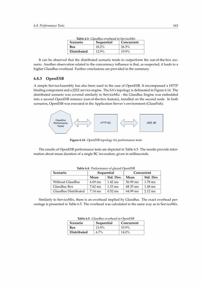
6.8. Performance Tests 163
Table 6.3: GlassBus overhead in ServiceMixScenario Sequential ConcurrentBox 18.2% 26.5%Distributed 12.9% 19.9%
It can be observed that the distributed scenario tends to outperform the out-of-the-box sce-nario. Another observation related to the concurrency influence is that, as suspected, it leads to ahigher GlassBus overhead. Further conclusions are provided in the summary.
6.8.3 OpenESB
A simple ServiceAssembly has also been used in the case of OpenESB. It encompassed a HTTPbinding component and a J2EE service engine. The SA’s topology is delineated in Figure 6.14. Thedistributed scenario was covered similarly to ServiceMix - the GlassBus Engine was embeddedinto a second OpenESB instance (out-of-the-box feature), installed on the second node. In bothscenarios, OpenESB was executed in the Application Server’s environment (GlassFish).
Figure 6.14: OpenESB topology for performance tests
The results of OpenESB performance tests are depicted in Table 6.5. The results provide infor-mation about mean duration of a single BC invocation, given in milliseconds.
Table 6.4: Performance of glazed OpenESBScenario Sequential Concurrent
Mean Std. Dev. Mean Std. DevWithout GlassBus 6.69 ms 1.42 ms 56.99 ms 1.78 msGlassBus Box 7.62 ms 1.33 ms 68.35 ms 1.48 msGlassBus Distributed 7.14 ms 0.52 ms 64.99 ms 2.12 ms
Similarly to ServiceMix, there is an overhead implied by GlassBus. The exact overhead per-centage is presented in Table 6.5. The overhead was calculated in the same way as in ServiceMix.
Table 6.5: GlassBus overhead in OpenESBScenario Sequential ConcurrentBox 13.9% 19.9%Distributed 6.7% 14.0%
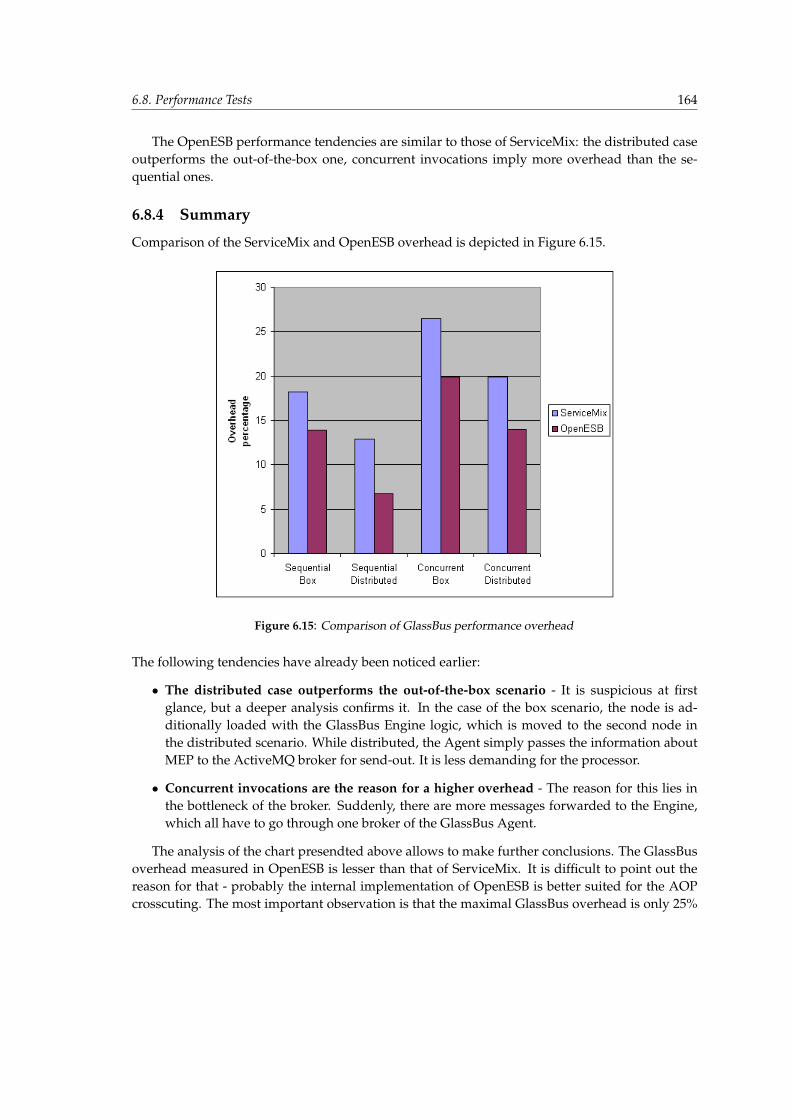
6.8. Performance Tests 164
The OpenESB performance tendencies are similar to those of ServiceMix: the distributed caseoutperforms the out-of-the-box one, concurrent invocations imply more overhead than the se-quential ones.
6.8.4 Summary
Comparison of the ServiceMix and OpenESB overhead is depicted in Figure 6.15.
Figure 6.15: Comparison of GlassBus performance overhead
The following tendencies have already been noticed earlier:
• The distributed case outperforms the out-of-the-box scenario - It is suspicious at firstglance, but a deeper analysis confirms it. In the case of the box scenario, the node is ad-ditionally loaded with the GlassBus Engine logic, which is moved to the second node inthe distributed scenario. While distributed, the Agent simply passes the information aboutMEP to the ActiveMQ broker for send-out. It is less demanding for the processor.
• Concurrent invocations are the reason for a higher overhead - The reason for this lies inthe bottleneck of the broker. Suddenly, there are more messages forwarded to the Engine,which all have to go through one broker of the GlassBus Agent.
The analysis of the chart presendted above allows to make further conclusions. The GlassBusoverhead measured in OpenESB is lesser than that of ServiceMix. It is difficult to point out thereason for that - probably the internal implementation of OpenESB is better suited for the AOPcrosscuting. The most important observation is that the maximal GlassBus overhead is only 25%
6.9. Conclusion 165
(Concurrent Box of ServiceMix) and it is the only case of exceeding the overhead to more than20%. It has to be stressed that the tests were intentionally performed on an empty business logic.In real JBI usage scenarios, the business logic is probably much heavier, which will result in alower overhead of GlassBus. It can be concluded that the GlassBus’s overhead is acceptably low.It is an affordable cost of having monitoring/management systems with such a wide scope offunctionalities.
6.9 Conclusion
The GlassBus Implementation chapter is an important supplement of the previous one, which providedjustification for architectural design decisions, giving good background for logical and physical structureinformation enclosed here.
The chapter contains many important information, which is significant for understanding GlassBusscapabilities. Along with the domain messaging model, an analysis of the JBI Message Exchange Patternstiming path is performed. It has been concluded that the most important timing information is related tothe processing time (part 3 of timing path), which allows to monitor performance of the logic execution andalso propagation of the fault and status. In the description of the GlassBus Agent and the GlassBus Engine,focus was put on identification of inter-component interfaces. Thanks to that the three main scenariosdescribed on the invocation flows - agent registration, topology propagation and messaging propagation -are more lucid.
Next very important section is the External monitoring interface (6.3.4). It contains a definition ofinterfaces exposed by GlassBus. The interface related to the topology is not complex - its structure doesnot extend the topology model introduced earlier. The Messaging interface is related to many statisticsand therefore it is less trivial. The abstraction model is introduced in order to demystify the semantics andmethods from the external interface of messaging. It is supplemented by details of the Pattern messaginginterface introduced on the basis of illustrated definitions of GlassBuss notions provided in Section 4.4.
As it has been concluded in Chapter 3, a monitoring system is unusable without proper selectivity andmanagement. Proper facilities have been introduced and described in Section 6.3.5. Unfortunately, the highcomplexity of the JBI monitoring subject and the completeness of the GlassBus solution made it impossibleto provide a fully functional and complete implementation - it is justified in Section 6.7. Fortunately, theperformance tests prove the correctness of the GlassBus architecture and assure that a full implementationis realizable.
Chapter 7
Conclusions
Victory has a thousand fathers, but defeat is an orphan. John F. Kennedy, American Statesman and35th U.S. president.
7.1 Overview
The main goal of this thesis was to provide a usable solution capable of monitoring systems com-pliant with JSR-208 specification, i.e. implementations of Java Business Integration. Focus hasbeen put on the OpenESB and ServiceMix solutions, which at the beginning of the work on thisthesis were the main projects that supported the specification. The main JBI concepts have beenpresented in the second chapter (2), starting from a general subject of enterprise integration, goingthrough the definitions of Enterprise Service Bus and finally identifying the JBI container as anattempt of ESB standardization. As it turned out later in the third chapter (3), JBI does not strictlyconform to all ESB assumptions. It lacks the standardization of clustering and distribution, whichare essential for the concept of ESB federations. Nevertheless, it has been decided to fully supportthe features of ServiceMix and OpenESB. The analysis of the JBI status quo and theorems relatedto the application monitoring in the third chapter proved the JBI monitoring to be a significantchallenge, which has been accepted by the authors of this thesis.
The proper requirements with the division into functional and non-functional have been statedin the fourth chapter (4), giving a more precise projection of the GlassBus goals. The most impor-tant part of the GlassBus system description has been enclosed in the fifth chapter (5). Fortunatelyor not, the authors were forced to make a set of experiments which evaluate several possible re-alizations of a given system’s elements and finally to decide on the best possible solution. Eachof these experiments is introduced as a separate section of the fifth chapter (5). Throughout theevaluation of the experiments, all requirements from the fourth chapter (4) were constantly beingreferred to, which allowed to choose the realizations maintaining compliance with the functionaland non-functional goals of GlassBus. It has to be admitted that reviewing the requirement com-pliance tables provided in the fifth chapter (5) leads to the conclusion that all GlassBus goals havebeen achieved. Of course, the high complexity of the solution, which is further described in thesixth chapter (6), did not allow to implement a fully functional production system. Instead, aresearch version of GlassBus has been provided which is a fully functional skeleton of the JBImonitoring solution. Therefore, it can be summarized that all goals of the architecture designhave been achieved, but not all of them have been implemented. Their implementation has beenpostponed for future work on the GlassBus system.
7.2. The status of Java Business Integration 167
7.2 The status of Java Business Integration
Future applicability of GlassBus depends heavily on the status of JBI itself. When the JBI emergedin August 2005, it was a promising attempt of ESB standardization, which was identified as hav-ing the potential of changing the balance of the enterprise solution market. Unfortunately, earlyon two most important partners of expert group: IBM and BEA backed off from supporting JBI.Fortunately, heavy support of Sonic, TIBCO and Sun allowed to overcome these initial difficultiesand to provide a solution changing the face of ESB. It is difficult to objectively judge the successof JBI. There are many users who are satisfied with JBI incorporated in their enterprise infrastruc-ture. There are, however, also some critical opinions. In the article of Darryl K. Taft, Mark Little,director of Standards and JBoss ESB, justifies the JBI problems in the following way: ”It was abit too early (...) It got caught up in the Web services hype of 2005 when Web services was a bigselling point of J2EE.” [98]. Another negative opinion given by an anonymous observer is thefollowing: ”JBI 1.0 was not ready for prime time; it focused on vendor needs and not the user,and has been a miserable failure. This is why you saw BEA and IBM, for instance, walk away anddo SCA [Service Component Architecture]. If someone wants to write an ESB app today, it willnot be portable to other ESBs. We think this is a horrible situation to put customers in, when SOAis about reusability, interoperability and flexibility.” [98].
Recently, it has turned out that JBI has to face a new trend of inclining towards more lightweightsolutions. The reason for this lies in the increasing quality of the solutions providing a partial ESBmechanism. Every Enterprise Bus encompasses: messaging backbone, orchestration engine andsome binding connectors. Currently, there are many solutions which can be recommended for therealization of those ESB elements. For example, Artur Karazniewicz in his comment on LinkedInportal [89] recommends the following combination: ”JAX-WS and JAXB as a SOAP connectiv-ity, Active MQ as a messaging backbone, Apache Camel as a orchestration engine and Spring toglue it all”. Such a combination can be successfully used as a comprehensive and feature-richEnterprise Service Bus substitution, which reveals the fact that it is not difficult to achieve func-tionalities similar to ESB or JBI without a heavy bus infrastructure. Such a tendency naturallyleads to questioning the need of JBI.
7.3 Future of JSR-208 - JBI 2.0
In order to tackle the JBI shortcomings, the creation of a new version of the specification wasinitiated in the form of Java Specification Request 312 [4]. Unfortunately, JBI 2.0 along with itspredecessor has been identified as competitive to the Service Component Architecture [44]. SCAis based on a composite application model and, contrary to JBI, it is multi-lingual: Java, C++,Spring, PHP, Ruby, WSDL are supported. It is commented as a ”new programming model forcreating service-oriented components in Java (and C++), and a way to describe how componentsare assembled into groups called composites” [99]. The SCA alternative is the reason for sus-taining the lack of JBI 2.0 support by BEA: ”We remain unconvinced of the value of a Java-onlysolution for SOA (...) BEA believes that the Java community will be better served with a multi-platform, multi-language SOA standard like SCA than anything that can be developed solely forJava. As such, we would prefer that a new JBI expert group not be formed.” [98].
The situation is similar - BEA and IBM deny supporting JBI initiative. This time, however,
7.3. Future of JSR-208 - JBI 2.0 168
the specification is created with an approach that will hopefully overcome the lack of this vitalsupport. First of all, the aim of JBI 2.0 is not to compete with SCA, but to enhance its architecture[99]:
• JBI can provide the key features for a runtime platform for SCA;
• There is very little overlap;
• JBI containers should be able to consume the SCA metadata;
• The tools should be able to take the SCA composite definitions and create JBI Service As-semblies and Service Units.
Such an approach rejects the BEA arguments against JBI. Additionally, according to Peter Walker’spresentation from June 2007 [99], JBI 2.0 answers many shortcomings of JSR-208 by introducingimportant features: Maintain definition of JBI for Java SE, Interceptors, Standard interfaces for ex-pected services, POJOs as JBI components, Runtime Management enhancement, Clustering/dis-tribution, Fault tolerance and reliability.
From the GlassBus’s point of view, what is most important is the standardization of clustering,which has been mentioned several times as a significant problem and the reason for incompatibil-ities between ServiceMix and OpenESB. The second feature of great importance is the mechanismof interceptors. It is defined the in following way: ”Interceptors provide the ability to affect theprocessing of a message exchange without code and configuration changes (...) Interceptors of-fer an opportunity to address cross-cutting concerns in JBI architecture” [99]. The mechanismof interceptors has been identified as being very similar to GlassBus’s mechanism of gatheringmonitoring information, which is based on the AOP crosscutting. A hypothesis can be stated thatthe standardization of clustering and the interceptors mechanism could allow for an easy inte-gration of GlassBus with JBI 2.0-compliant container. Of course, the hypothesis will be verifiedwhen JBI 2.0 is released. Unfortunately, since April 2007 there has been no update on the JSR-312homepage.
Taking account of the critical opinions about JBI 1.0, the developers of JBI containers are morecautious and try to provide a broader scope of functionalities which cover both SCA and the up-coming JBI 2.0. For example, ServiceMix 4.0 release is commented in the following way: ”Themain focus is ease of use: while ServiceMix 3.x has mainly focused on JBI 1.0, the 4.0 versionwill go further and really leverage the good in JBI 1.0, while getting around the difficult parts toprovide a flexible, powerful and easy API (...) ServiceMix 4.x also aims to support JBI 2.0 andSCA, so we will try to understand at how they can be leveraged together.” [87]. JBI 2.0 giveshope for mitigating the drawbacks of its predecessor and proving that the standardization of ESBis possible and beneficial. Watching the enterprise market reveals the fact that some ESB imple-mentations are backing off from JBI compliance. However, new versions of the most popular JBIcontainer evaluated in this thesis: ServiceMix 4.0 and OpenESB 2.0 plan to sustain the JBI sup-port. It is definitely good news for GlassBus. Its architecture is flexible and lacks assumptions,which would made GlassBus’s evolution towards these new JBI container versions impossible.This conclusion along with the market trends and directions of JBI containers’ evolution suggeststhat a distributed JBI 2.0 container should be the primary focus of future GlassBus work. It wouldbe also wise to take into account some extension towards SCA, which would boost the potentialof GlassBus innovation.

7.4. GlassBus achievement 169
7.4 GlassBus achievement
The GlassBus challenge turned out to be really demanding. Great amount of work was needed inorder to provide a solution compliant with all stated requirements. The quantity of work can beestimated by the statistics depicted in Table 7.1 and 7.2.
Table 7.1: GlassBus effort perspectiveNumber of classes 67Number of code lines 4181Number of configuration lines 2979Number of methods crosscut through AOP 28Number of external libraries used 39Number of months of constant work 9
Table 7.2: Proof-of-Concept projects effort perspectiveNumber of PoC projects 8Number of classes 152Number of code lines 3734Number of configuration lines 4837Number of external libraries used 151
In the end, it turned out that putting so much effort has been well worthwhile. Despite someshortcomings of JBI specifications, a functional and innovative realization of JBI monitoring solu-tion has been possible. All GlassBus goals stated in the executive summary have been achieved.There are some imperfections of the correlation heuristics related to assumptions about the pro-cessing of JBI message exchanges that are not always true. It was the cost of the high JBI com-pliance, which was one of the most important requirements. There was always a possibility ofbreaking the compliance and constructing a deterministic mechanism, but it would have to beproprietary to either ServiceMix or OpenESB. This would not be pure JBI monitoring anymore.As mentioned before, providing a fully functional implementation was impossible due to thehigh subject complexity. However, the GlassBus skeleton which has been delivered was capableof evaluating all crucial performance issues. The performance tests (6.8) assured that GlassBushas a minor influence on the JBI container’s performance. This suffices the most important re-quirement and ensures GlassBus’s success not only in the field of JBI 1.0, but also in the nearfuture of JSR-312.
GlassBus success can be verified by proving the truth of the thesis statement defined in theintroduction. After all dissertation steps: theoretical foundation, requirements formulation, re-search, implementation, experimental verification, the thesis statement can be reformulated inthe following way:
The GlassBus processing model resulted in the construction of a system that adds monitoring and manage-ment logic to a Java Business Integration container, in such a way that the logic is fully transparent and

7.4. GlassBus achievement 170
compliant with the JBI specification. GlassBus allows to gather, process and expose sophisticated informa-tion regarding the qualitative parameters and operational reliability of the JBI container.

Appendices
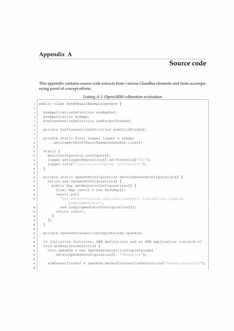
Appendix A
Source code
This appendix contains source code extracts from various GlassBus elements and from accompa-nying proof of concept efforts.
Listing A.1: OpenARM colleration evaluation
1 public class Arm40BasicExampleOpenArm {2
3 ArmApplicationDefinition armAppDef ;4 ArmApplication armApp ;5 ArmTransactionDefinition armParentTranDef ;6
7 private ArmTransactionDefinition armChildTranDef ;8
9 private static final Logger logger = Logger10 .getLogger (Arm40BasicExampleOpenArm .class ) ;11
12 static {13 BasicConfigurator .configure ( ) ;14 logger .getLoggerRepository ( ) .setThreshold ("ALL" ) ;15 logger .info ("[initializeLogging] Configured!" ) ;16 }17
18 private static OpenArmConfiguration obtainOpenArmConfiguration ( ) {19 return new OpenArmConfiguration ( ) {20 public Map getMediatorConfigurations ( ) {21 final Map result = new HashMap ( ) ;22 result .put (23 "net.m2technologies.open_arm.transport.transaction.logging.
LoggingMediator" ,24 new LoggingMediatorConfiguration ( ) ) ;25 return result ;26 }27 } ;28 }29
30 private OpenArmTransactionSimpleFacade openArm ;31
32 /∗ initialize factories , ARM definitions and an ARM application instance ∗/33 void armRegisterAndInit ( ) {34 this .openArm = new OpenArmTransactionSimpleFacade (35 obtainOpenArmConfiguration ( ) , "JExamples" ) ;36
37 armParentTranDef = openArm .getArmTransactionDefinition ("JExampleParentTx" ) ;38

173
39 armChildTranDef = openArm .getArmTransactionDefinition ("JExampleChildTx" ) ;40
41 }42
43 public void run ( ) {44 armRegisterAndInit ( ) ;45
46 ArmTransaction armParentTran = openArm47 .getArmTransactionMonitor (armParentTranDef ) ;48
49 armParentTran .start ( ) ;50
51 int childStatus = ArmConstants .STATUS_GOOD ;52 if ( ! childTransaction (armParentTran .getCorrelator ( ) ) )53 childStatus = ArmConstants .STATUS_FAILED ;54
55 armParentTran .stop (childStatus ) ;56 }57
58 /∗59 ∗ In−process nested transaction . The return value signals successful60 ∗ completion status .61 ∗/62 private boolean childTransaction (ArmCorrelator correlator ) {63 ArmTransaction armChildTran = openArm64 .getArmTransactionMonitor (armChildTranDef ) ;65
66 armChildTran .start (correlator ) ;67
68 armChildTran .stop (ArmConstants .STATUS_GOOD ) ;69
70 return true ;71 }72 }
Listing A.2: JMS sender proprietary implementation
1 package pl .edu .agh .glassbus .agent .sender ;2
3 import java .io .Serializable ;4
5 import javax .jms .ConnectionFactory ;6 import javax .jms .JMSException ;7 import javax .jms .Message ;8 import javax .jms .Queue ;9 import javax .jms .QueueConnection ;
10 import javax .jms .QueueSender ;11 import javax .jms .QueueSession ;12 import javax .jms .Session ;13
14 /∗∗15 ∗ Simplest and f a s t e s t implementation of the JMS sender l o g i c ;16 ∗
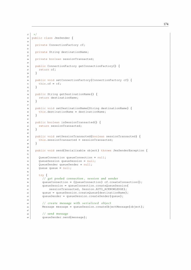
174
17 ∗/18 public class JmsSender {19
20 private ConnectionFactory cf ;21
22 private String destinationName ;23
24 private boolean sessionTransacted ;25
26 public ConnectionFactory getConnectionFactory ( ) {27 return cf ;28 }29
30 public void setConnectionFactory (ConnectionFactory cf ) {31 this .cf = cf ;32 }33
34 public String getDestinationName ( ) {35 return destinationName ;36 }37
38 public void setDestinationName (String destinationName ) {39 this .destinationName = destinationName ;40 }41
42 public boolean isSessionTransacted ( ) {43 return sessionTransacted ;44 }45
46 public void setSessionTransacted (boolean sessionTransacted ) {47 this .sessionTransacted = sessionTransacted ;48 }49
50 public void send (Serializable object ) throws JmsSenderException {51
52 QueueConnection queueConnection = null ;53 QueueSession queueSession = null ;54 QueueSender queueSender = null ;55 Queue queue = null ;56
57 try {58 // get pooled connection , s e s s i o n and sender59 queueConnection = (QueueConnection ) cf .createConnection ( ) ;60 queueSession = queueConnection .createQueueSession (61 sessionTransacted , Session .AUTO_ACKNOWLEDGE ) ;62 queue = queueSession .createQueue (destinationName ) ;63 queueSender = queueSession .createSender (queue ) ;64
65 // c r e a t e message with s e r i a l i z e d o b j e c t66 Message message = queueSession .createObjectMessage (object ) ;67
68 // send message69 queueSender .send (message ) ;
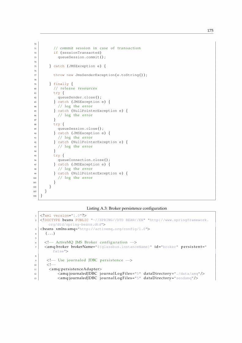
175
70
71 // commit s e s s i o n in case of t r a n s a c t i o n72 if (sessionTransacted )73 queueSession .commit ( ) ;74
75 } catch (JMSException e ) {76
77 throw new JmsSenderException (e .toString ( ) ) ;78
79 } finally {80 // r e l e a s e resources81 try {82 queueSender .close ( ) ;83 } catch (JMSException e ) {84 // log the e r r o r85 } catch (NullPointerException e ) {86 // log the e r r o r87 }88 try {89 queueSession .close ( ) ;90 } catch (JMSException e ) {91 // log the e r r o r92 } catch (NullPointerException e ) {93 // log the e r r o r94 }95 try {96 queueConnection .close ( ) ;97 } catch (JMSException e ) {98 // log the e r r o r99 } catch (NullPointerException e ) {
100 // log the e r r o r101 }102 }103 }104 }
Listing A.3: Broker persistence configuration
1 <?xml version="1.0"?>2 < !DOCTYPE beans PUBLIC "-//SPRING//DTD BEAN//EN" "http://www.springframework.
org/dtd/spring-beans.dtd">3 <beans xmlns:amq="http://activemq.org/config/1.0">4 ( . . . )5
6 < !−− ActiveMQ JMS Broker c o n f i g u r a t i o n −−>7 <amq:broker brokerName="${glassbus.instanceName}" id="broker" p e r s i s t e n t ="
false">8
9 < !−− Use journaled JDBC p e r s i s t e n c e −−>10 < !−−11 <amq:persistenceAdapter>12 <amq:journaledJDBC j o u r n a l L o g F i l e s ="5" dataDirec tory="./data/amq"/>13 <amq:journaledJDBC j o u r n a l L o g F i l e s ="5" dataDirec tory="sendamq"/>

176
14 <amq:kahaPersistenceAdapter d i r="sendamq" maxDataFileLength="33554432"/>
15 <amq:journaledJDBC j o u r n a l L o g F i l e s ="5" dataDirec tory="../data"dataSource="#postgres-ds"/>
16 </amq:persistenceAdapter>17 −−>18 </amq:broker>19 < !−− This xbean c o n f i g u r a t i o n f i l e supports a l l the standard spring xml
c o n f i g u r a t i o n options −−>20
21 < !−− Postgres DataSource Sample Setup −−>22 < !−−23 <bean id="postgres-ds" c l a s s ="org.postgresql.ds.PGPoolingDataSource">24 <property name="serverName" value="localhost"/>25 <property name="databaseName" value="activemq"/>26 <property name="portNumber" value="0"/>27 <property name="user" value="activemq"/>28 <property name="password" value="activemq"/>29 <property name="dataSourceName" value="postgres"/>30 <property name="initialConnections" value="1"/>31 <property name="maxConnections" value="10"/>32 </bean>33 −−>34
35 < !−− MySql DataSource Sample Setup using the Commons DBCP pooler ( h t t p : //j a k a r t a . apache . org/commons/dbcp /) −−>
36 < !−−37 <bean id="mysql-ds" c l a s s ="org.apache.commons.dbcp.BasicDataSource" destroy−
method="close">38 <property name="driverClassName" value="com.mysql.jdbc.Driver"/>39 <property name="url" value="jdbc:mysql://localhost/activemq"/>40 <property name="username" value="activemq"/>41 <property name="password" value="activemq"/>42 <property name="poolPreparedStatements" value="true"/>43 </bean>44 −−>45
46 < !−− MySql DataSource Sample Setup using the c3p0 pooler ( h t t p : // s f . net/p r o j e c t s /c3p0 ) −−>
47 < !−−48 <bean id="mysql-ds" c l a s s ="com.mchange.v2.c3p0.ComboPooledDataSource" destroy
−method="close">49 <property name="driverClass" value="com.mysql.jdbc.Driver">50 <property name="jdbcUrl" value="jdbc:mysql://localhost:3306/activemq">51 <property name="user" value="activemq">52 <property name="password" value="activemq">53 <property name="minPoolSize" value="5">54 <property name="maxPoolSize" value="10">55 <property name="acquireIncrement" value="3">56 </bean>57 −−>58
59 < !−− Embedded Derby DataSource Sample Setup −−>
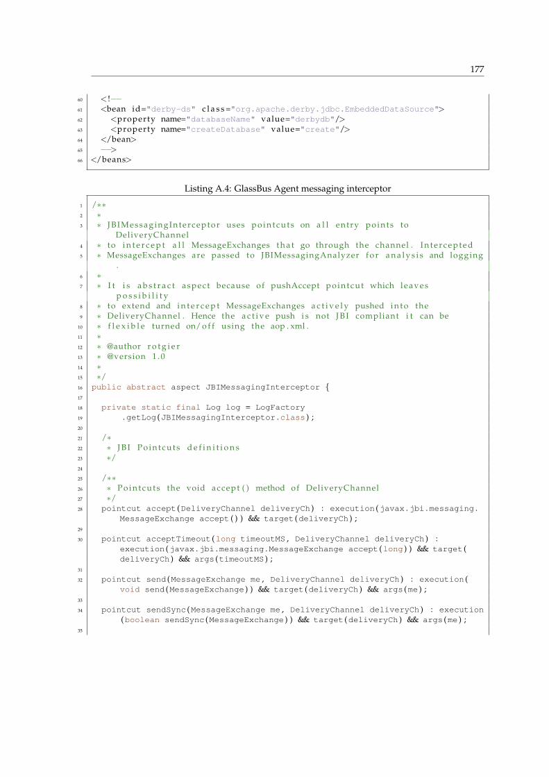
177
60 < !−−61 <bean id="derby-ds" c l a s s ="org.apache.derby.jdbc.EmbeddedDataSource">62 <property name="databaseName" value="derbydb"/>63 <property name="createDatabase" value="create"/>64 </bean>65 −−>66 </beans>
Listing A.4: GlassBus Agent messaging interceptor
1 /∗∗2 ∗3 ∗ JBIMessagingInterceptor uses p o in t cu t s on a l l entry points to
DeliveryChannel4 ∗ to i n t e r c e p t a l l MessageExchanges t h a t go through the channel . I n t e r c e p t e d5 ∗ MessageExchanges are passed to JBIMessagingAnalyzer f o r a n a l y s i s and logging
.6 ∗7 ∗ I t i s a b s t r a c t aspect because of pushAccept pointcut which leaves
p o s s i b i l i t y8 ∗ to extend and i n t e r c e p t MessageExchanges a c t i v e l y pushed i n t o the9 ∗ DeliveryChannel . Hence the a c t i v e push i s not J B I compliant i t can be
10 ∗ f l e x i b l e turned on/ o f f using the aop . xml .11 ∗12 ∗ @author r o t g i e r13 ∗ @version 1 . 014 ∗15 ∗/16 public abstract aspect JBIMessagingInterceptor {17
18 private static final Log log = LogFactory19 .getLog (JBIMessagingInterceptor .class ) ;20
21 /∗22 ∗ J B I Po in t cu ts d e f i n i t i o n s23 ∗/24
25 /∗∗26 ∗ Po in tcu ts the void accept ( ) method of DeliveryChannel27 ∗/28 pointcut accept (DeliveryChannel deliveryCh ) : execution (javax .jbi .messaging .
MessageExchange accept ( ) ) && target (deliveryCh ) ;29
30 pointcut acceptTimeout (long timeoutMS , DeliveryChannel deliveryCh ) :execution (javax .jbi .messaging .MessageExchange accept (long ) ) && target (deliveryCh ) && args (timeoutMS ) ;
31
32 pointcut send (MessageExchange me , DeliveryChannel deliveryCh ) : execution (void send (MessageExchange ) ) && target (deliveryCh ) && args (me ) ;
33
34 pointcut sendSync (MessageExchange me , DeliveryChannel deliveryCh ) : execution(boolean sendSync (MessageExchange ) ) && target (deliveryCh ) && args (me ) ;
35

178
36 pointcut sendSyncTimeout (MessageExchange me , long timeoutMS ,37 DeliveryChannel deliveryCh ) : execution (boolean sendSync (MessageExchange ,
long ) ) && target (deliveryCh ) && args (me ,timeoutMS ) ;38
39 /∗∗40 ∗ This a b s t r a c t pointcut leaves a p o s s i b i l i t y to def ine pointcut which41 ∗ i n t e r c e p t s not pul l ing the MessageExchange ( l i k e regular J B I ’ s accept42 ∗ methods ) but pushing i t to the DeliveryChannel . I t h i s s c e n a r i o sender i s43 ∗ pushing MessageExchange to r e c i e v e r by invoking some method on r e c i e v e r ’ s44 ∗ DeliveryChannel and passing MessageExchange as argument .45 ∗46 ∗ DeliveryChannel ’ s implementation47 ∗48 ∗ @param me49 ∗ @param deliveryCh50 ∗/51 abstract pointcut pushAccept ( ) ;52
53 void beforeSend (MessageExchange me , DeliveryChannel deliveryCh ,54 String component ) {55 GlassbusAgent .msgProc .processInterceptedSend (CorrelatorsExecutor56 .correlate (me , component ) , me ) ;57 }58
59 void around (MessageExchange me , DeliveryChannel deliveryCh )60 throws Exception : send (me , deliveryCh ) {61 try {62 if (DeliveryChannelInfo .deliveryChannelMemory63 .containsKey (deliveryCh .hashCode ( ) ) ) {64 DeliveryChannelInfo dc = DeliveryChannelInfo .deliveryChannelMemory65 .get (deliveryCh .hashCode ( ) ) ;66 if (dc .isStarted ) {67 if (log .isDebugEnabled ( ) )68 log .debug ("Intercepting send in component: " + dc .name ) ;69 if (log .isTraceEnabled ( ) )70 log .trace ("Intercepting send with:\nme: " + me71 + "\ndeliveryChannel: " + deliveryCh ) ;72 beforeSend (me , deliveryCh , dc .name ) ;73 } else {74 if (log .isWarnEnabled ( ) )75 log .warn ("Intercepting send in stopped component: "76 + dc .name ) ;77 }78 } else {79 if (log .isTraceEnabled ( ) )80 log81 .trace ("Intercepting send with unknown DeliveryChannel: "82 + deliveryCh ) ;83 }84 proceed (me , deliveryCh ) ;85 } catch (MessagingException e ) {86 if (log .isDebugEnabled ( ) )87 log .debug ("MessagingException in send" , e ) ;
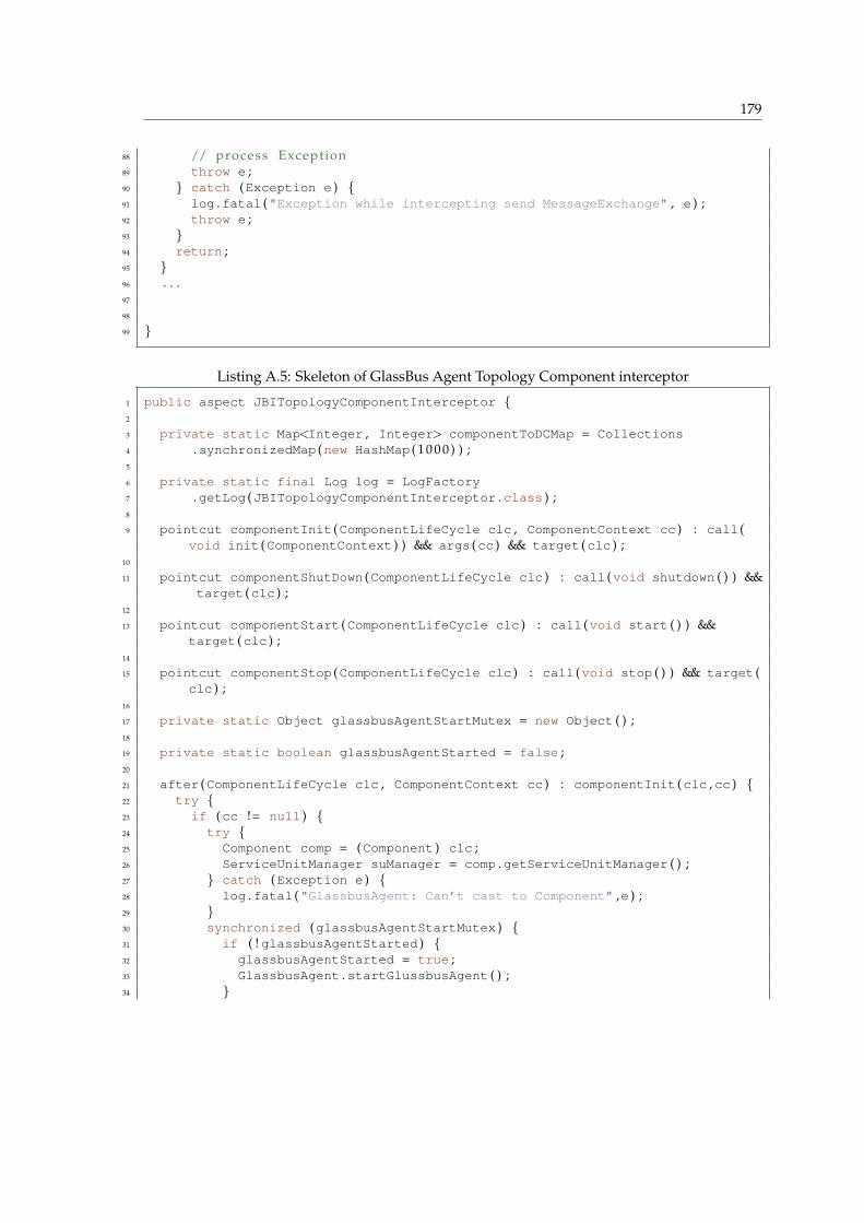
179
88 // process Exception89 throw e ;90 } catch (Exception e ) {91 log .fatal ("Exception while intercepting send MessageExchange" , e ) ;92 throw e ;93 }94 return ;95 }96 . . .97
98
99 }
Listing A.5: Skeleton of GlassBus Agent Topology Component interceptor
1 public aspect JBITopologyComponentInterceptor {2
3 private static Map<Integer , Integer> componentToDCMap = Collections4 .synchronizedMap (new HashMap ( 1 0 0 0 ) ) ;5
6 private static final Log log = LogFactory7 .getLog (JBITopologyComponentInterceptor .class ) ;8
9 pointcut componentInit (ComponentLifeCycle clc , ComponentContext cc ) : call (void init (ComponentContext ) ) && args (cc ) && target (clc ) ;
10
11 pointcut componentShutDown (ComponentLifeCycle clc ) : call (void shutdown ( ) ) &&target (clc ) ;
12
13 pointcut componentStart (ComponentLifeCycle clc ) : call (void start ( ) ) &&target (clc ) ;
14
15 pointcut componentStop (ComponentLifeCycle clc ) : call (void stop ( ) ) && target (clc ) ;
16
17 private static Object glassbusAgentStartMutex = new Object ( ) ;18
19 private static boolean glassbusAgentStarted = false ;20
21 after (ComponentLifeCycle clc , ComponentContext cc ) : componentInit (clc ,cc ) {22 try {23 if (cc != null ) {24 try {25 Component comp = (Component ) clc ;26 ServiceUnitManager suManager = comp .getServiceUnitManager ( ) ;27 } catch (Exception e ) {28 log .fatal ("GlassbusAgent: Can’t cast to Component" ,e ) ;29 }30 synchronized (glassbusAgentStartMutex ) {31 if ( ! glassbusAgentStarted ) {32 glassbusAgentStarted = true ;33 GlassbusAgent .startGlussbusAgent ( ) ;34 }
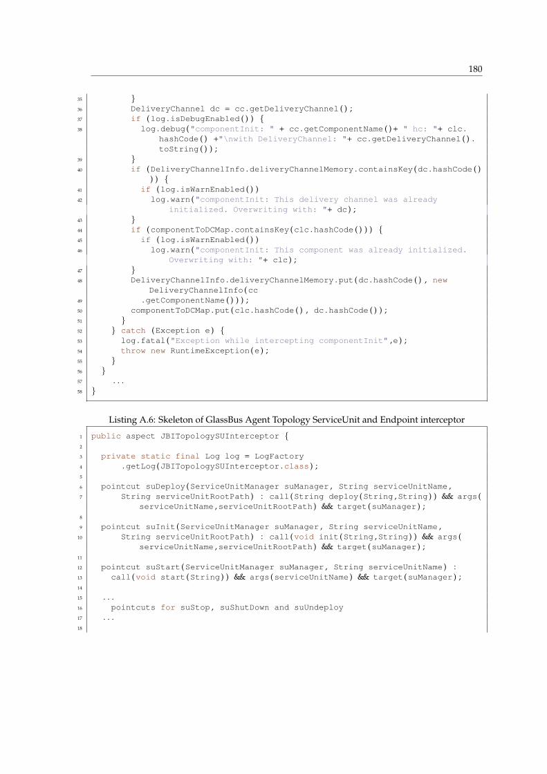
180
35 }36 DeliveryChannel dc = cc .getDeliveryChannel ( ) ;37 if (log .isDebugEnabled ( ) ) {38 log .debug ("componentInit: " + cc .getComponentName ( ) + " hc: "+ clc .
hashCode ( ) +"\nwith DeliveryChannel: "+ cc .getDeliveryChannel ( ) .toString ( ) ) ;
39 }40 if (DeliveryChannelInfo .deliveryChannelMemory .containsKey (dc .hashCode ( )
) ) {41 if (log .isWarnEnabled ( ) )42 log .warn ("componentInit: This delivery channel was already
initialized. Overwriting with: "+ dc ) ;43 }44 if (componentToDCMap .containsKey (clc .hashCode ( ) ) ) {45 if (log .isWarnEnabled ( ) )46 log .warn ("componentInit: This component was already initialized.
Overwriting with: "+ clc ) ;47 }48 DeliveryChannelInfo .deliveryChannelMemory .put (dc .hashCode ( ) , new
DeliveryChannelInfo (cc49 .getComponentName ( ) ) ) ;50 componentToDCMap .put (clc .hashCode ( ) , dc .hashCode ( ) ) ;51 }52 } catch (Exception e ) {53 log .fatal ("Exception while intercepting componentInit" ,e ) ;54 throw new RuntimeException (e ) ;55 }56 }57 . . .58 }
Listing A.6: Skeleton of GlassBus Agent Topology ServiceUnit and Endpoint interceptor
1 public aspect JBITopologySUInterceptor {2
3 private static final Log log = LogFactory4 .getLog (JBITopologySUInterceptor .class ) ;5
6 pointcut suDeploy (ServiceUnitManager suManager , String serviceUnitName ,7 String serviceUnitRootPath ) : call (String deploy (String ,String ) ) && args (
serviceUnitName ,serviceUnitRootPath ) && target (suManager ) ;8
9 pointcut suInit (ServiceUnitManager suManager , String serviceUnitName ,10 String serviceUnitRootPath ) : call (void init (String ,String ) ) && args (
serviceUnitName ,serviceUnitRootPath ) && target (suManager ) ;11
12 pointcut suStart (ServiceUnitManager suManager , String serviceUnitName ) :13 call (void start (String ) ) && args (serviceUnitName ) && target (suManager ) ;14
15 . . .16 pointcuts for suStop , suShutDown and suUndeploy17 . . .18
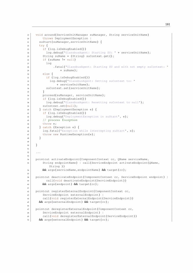
181
19 void around (ServiceUnitManager suManager , String serviceUnitName )20 throws DeploymentException :21 suStart (suManager ,serviceUnitName ) {22 try {23 if (log .isDebugEnabled ( ) )24 log .debug ("GlassbusAgent: Starting SU: " + serviceUnitName ) ;25 String suName = (String ) suContext .get ( ) ;26 if (suName != null )27 log28 .fatal ("GlassbusAgent: Starting SU and with not empty suContext: "29 + suName ) ;30 else {31 if (log .isDebugEnabled ( ) )32 log .debug ("GlassbusAgent: Setting suContext to: "33 + serviceUnitName ) ;34 suContext .set (serviceUnitName ) ;35 }36 proceed (suManager , serviceUnitName ) ;37 if (log .isDebugEnabled ( ) )38 log .debug ("GlassbusAgent: Resetting suContext to null" ) ;39 suContext .set (null ) ;40 } catch (DeploymentException e ) {41 if (log .isDebugEnabled ( ) )42 log .debug ("DeploymentException in suStart" , e ) ;43 // process Exception44 throw e ;45 } catch (Exception e ) {46 log .fatal ("Exception while intercepting suStart" , e ) ;47 throw new RuntimeException (e ) ;48 }49
50 }51
52 . . .53
54 pointcut activateEndpoint (ComponentContext cc , QName serviceName ,55 String endpointName ) : call (ServiceEndpoint activateEndpoint (QName ,
String ) )56 && args (serviceName ,endpointName ) && target (cc ) ;57
58 pointcut deactivateEndpoint (ComponentContext cc , ServiceEndpoint endpoint ) :59 call (void deactivateEndpoint (ServiceEndpoint ) )60 && args (endpoint ) && target (cc ) ;61
62 pointcut registerExternalEndpoint (ComponentContext cc ,63 ServiceEndpoint externalEndpoint ) :64 call (void registerExternalEndpoint (ServiceEndpoint ) )65 && args (externalEndpoint ) && target (cc ) ;66
67 pointcut deregisterExternalEndpoint (ComponentContext cc ,68 ServiceEndpoint externalEndpoint ) :69 call (void deregisterExternalEndpoint (ServiceEndpoint ) )70 && args (externalEndpoint ) && target (cc ) ;
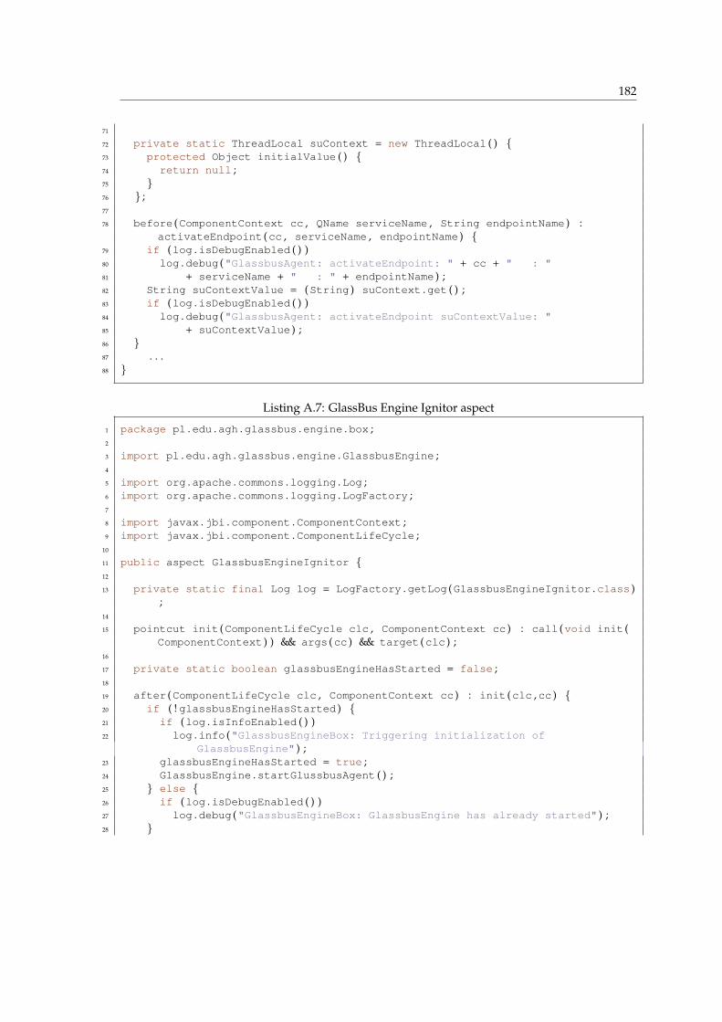
182
71
72 private static ThreadLocal suContext = new ThreadLocal ( ) {73 protected Object initialValue ( ) {74 return null ;75 }76 } ;77
78 before (ComponentContext cc , QName serviceName , String endpointName ) :activateEndpoint (cc , serviceName , endpointName ) {
79 if (log .isDebugEnabled ( ) )80 log .debug ("GlassbusAgent: activateEndpoint: " + cc + " : "81 + serviceName + " : " + endpointName ) ;82 String suContextValue = (String ) suContext .get ( ) ;83 if (log .isDebugEnabled ( ) )84 log .debug ("GlassbusAgent: activateEndpoint suContextValue: "85 + suContextValue ) ;86 }87 . . .88 }
Listing A.7: GlassBus Engine Ignitor aspect
1 package pl .edu .agh .glassbus .engine .box ;2
3 import pl .edu .agh .glassbus .engine .GlassbusEngine ;4
5 import org .apache .commons .logging .Log ;6 import org .apache .commons .logging .LogFactory ;7
8 import javax .jbi .component .ComponentContext ;9 import javax .jbi .component .ComponentLifeCycle ;
10
11 public aspect GlassbusEngineIgnitor {12
13 private static final Log log = LogFactory .getLog (GlassbusEngineIgnitor .class );
14
15 pointcut init (ComponentLifeCycle clc , ComponentContext cc ) : call (void init (ComponentContext ) ) && args (cc ) && target (clc ) ;
16
17 private static boolean glassbusEngineHasStarted = false ;18
19 after (ComponentLifeCycle clc , ComponentContext cc ) : init (clc ,cc ) {20 if ( ! glassbusEngineHasStarted ) {21 if (log .isInfoEnabled ( ) )22 log .info ("GlassbusEngineBox: Triggering initialization of
GlassbusEngine" ) ;23 glassbusEngineHasStarted = true ;24 GlassbusEngine .startGlussbusAgent ( ) ;25 } else {26 if (log .isDebugEnabled ( ) )27 log .debug ("GlassbusEngineBox: GlassbusEngine has already started" ) ;28 }

183
29
30 }31
32 }
Listing A.8: AOP XML configuration of ServiceMix
1 <?xml version="1.0" encoding="UTF-8"?>2 <a s p e c t j>3 <weaver>4 <inc lude within="org.apache.servicemix..*" />5 <inc lude within="org.apache.ode..*" />6 <inc lude within="javax.jbi..*" />7 <inc lude within="pl.edu.agh.glassbus..*" />8 </weaver>9 <as pec t s>
10 <concrete−aspect name="pl.edu.agh.glassbus.agent.interceptor.ServiceMixMessagingInterceptor"
11 extends="pl.edu.agh.glassbus.agent.interceptor.JBIMessagingInterceptor">12 <pointcut name="pushAccept"13 express ion="execution(void processInBound(org.apache.servicemix.jbi.
messaging.MessageExchangeImpl))" />14 </concrete−aspect>15 <aspect name="pl.edu.agh.glassbus.agent.interceptor.JBITopologyInterceptor"
/>16 <aspect name="pl.edu.agh.glassbus.agent.interceptor.
JBITopologySUInterceptor"/>17 </a spec t s>18 </ a s p e c t j>
Listing A.9: AOP XML configuration of OpenESB
1 <?xml version="1.0" encoding="UTF-8"?>2 <a s p e c t j>3 <weaver>4 <inc lude within="com.sun.jbi..*" />5 <inc lude within="com.sun.esb..*" />6 <inc lude within="javax.jbi..*" />7 <inc lude within="pl.edu.agh.glassbus..*" />8 </weaver>9 <as pec t s>
10 <concrete−aspect name="pl.edu.agh.glassbus.agent.analyzer"11 extends="pl.edu.agh.glassbus.agent.interceptor.JBIMessagingInterceptor">12 <pointcut name="pushAccept" express ion="!within(*)"/>13 </concrete−aspect>14 <aspect name="pl.edu.agh.glassbus.agent.interceptor.JBITopologyInterceptor"
/>15 <aspect name="pl.edu.agh.glassbus.agent.interceptor.
JBITopologySUInterceptor"/>16 </a spec t s>17 </ a s p e c t j>
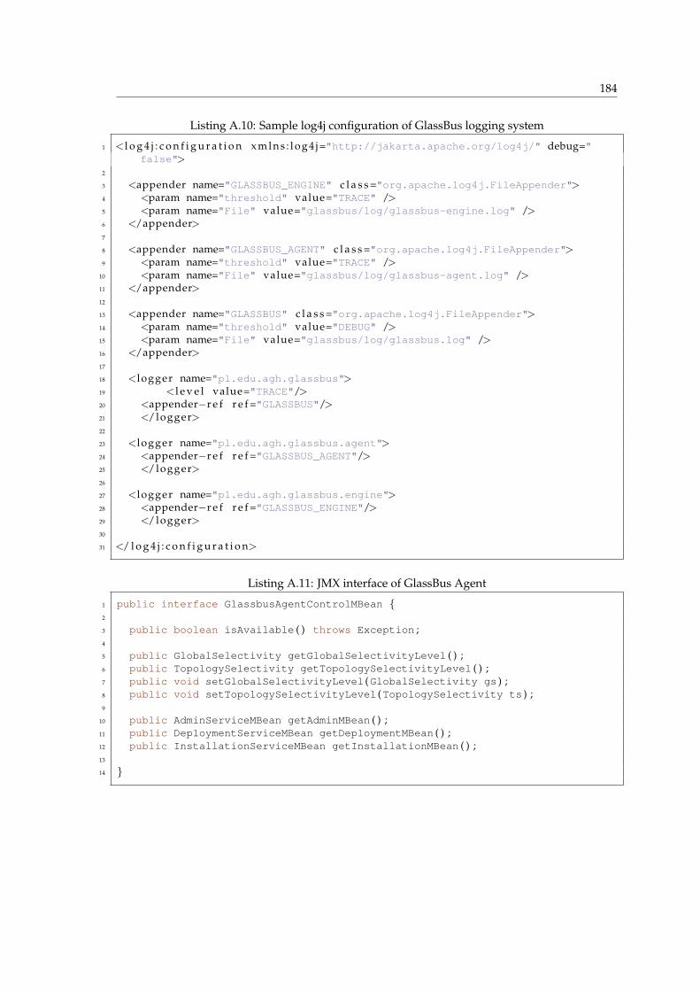
184
Listing A.10: Sample log4j configuration of GlassBus logging system
1 <l o g 4 j : c o n f i g u r a t i o n x m l n s : l o g 4 j="http://jakarta.apache.org/log4j/" debug="false">
2
3 <appender name="GLASSBUS_ENGINE" c l a s s ="org.apache.log4j.FileAppender">4 <param name="threshold" value="TRACE" />5 <param name="File" value="glassbus/log/glassbus-engine.log" />6 </appender>7
8 <appender name="GLASSBUS_AGENT" c l a s s ="org.apache.log4j.FileAppender">9 <param name="threshold" value="TRACE" />
10 <param name="File" value="glassbus/log/glassbus-agent.log" />11 </appender>12
13 <appender name="GLASSBUS" c l a s s ="org.apache.log4j.FileAppender">14 <param name="threshold" value="DEBUG" />15 <param name="File" value="glassbus/log/glassbus.log" />16 </appender>17
18 <logger name="pl.edu.agh.glassbus">19 <l e v e l value="TRACE"/>20 <appender−r e f r e f ="GLASSBUS"/>21 </logger>22
23 <logger name="pl.edu.agh.glassbus.agent">24 <appender−r e f r e f ="GLASSBUS_AGENT"/>25 </logger>26
27 <logger name="pl.edu.agh.glassbus.engine">28 <appender−r e f r e f ="GLASSBUS_ENGINE"/>29 </logger>30
31 </ l o g 4 j : c o n f i g u r a t i o n>
Listing A.11: JMX interface of GlassBus Agent
1 public interface GlassbusAgentControlMBean {2
3 public boolean isAvailable ( ) throws Exception ;4
5 public GlobalSelectivity getGlobalSelectivityLevel ( ) ;6 public TopologySelectivity getTopologySelectivityLevel ( ) ;7 public void setGlobalSelectivityLevel (GlobalSelectivity gs ) ;8 public void setTopologySelectivityLevel (TopologySelectivity ts ) ;9
10 public AdminServiceMBean getAdminMBean ( ) ;11 public DeploymentServiceMBean getDeploymentMBean ( ) ;12 public InstallationServiceMBean getInstallationMBean ( ) ;13
14 }
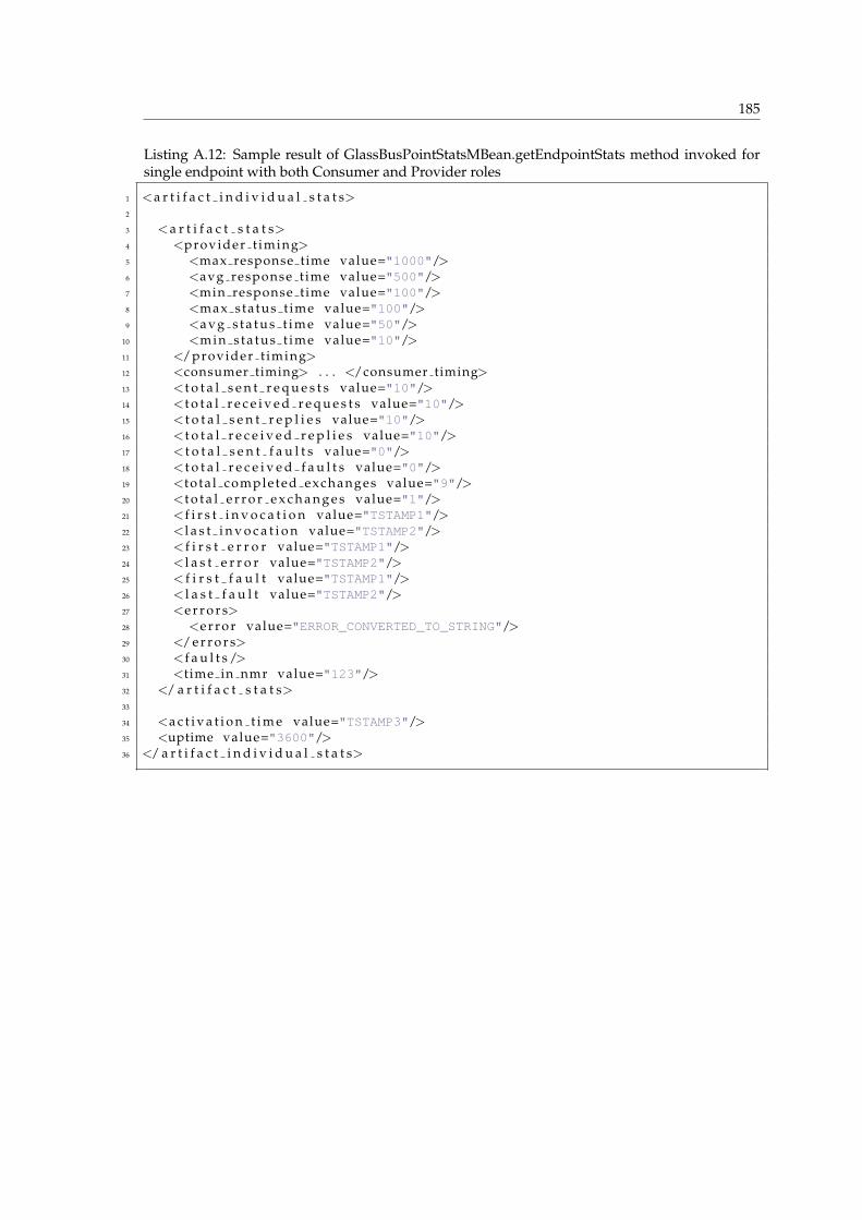
185
Listing A.12: Sample result of GlassBusPointStatsMBean.getEndpointStats method invoked forsingle endpoint with both Consumer and Provider roles
1 <a r t i f a c t i n d i v i d u a l s t a t s>2
3 <a r t i f a c t s t a t s>4 <provider t iming>5 <max response time value="1000"/>6 <avg response t ime value="500"/>7 <min response time value="100"/>8 <max status t ime value="100"/>9 <a v g s t a t u s t i m e value="50"/>
10 <min sta tus t ime value="10"/>11 </provider t iming>12 <consumer timing> . . . </consumer timing>13 <t o t a l s e n t r e q u e s t s value="10"/>14 <t o t a l r e c e i v e d r e q u e s t s value="10"/>15 < t o t a l s e n t r e p l i e s value="10"/>16 < t o t a l r e c e i v e d r e p l i e s value="10"/>17 < t o t a l s e n t f a u l t s value="0"/>18 < t o t a l r e c e i v e d f a u l t s value="0"/>19 <to ta l completed exchanges value="9"/>20 <t o t a l e r r o r e x c h a n g e s value="1"/>21 <f i r s t i n v o c a t i o n value="TSTAMP1"/>22 <l a s t i n v o c a t i o n value="TSTAMP2"/>23 < f i r s t e r r o r value="TSTAMP1"/>24 < l a s t e r r o r value="TSTAMP2"/>25 < f i r s t f a u l t value="TSTAMP1"/>26 < l a s t f a u l t value="TSTAMP2"/>27 <e r r o r s>28 <e r r o r value="ERROR_CONVERTED_TO_STRING"/>29 </ e r r o r s>30 <f a u l t s />31 <t ime in nmr value="123"/>32 </ a r t i f a c t s t a t s>33
34 <a c t i v a t i o n t i m e value="TSTAMP3"/>35 <uptime value="3600"/>36 </ a r t i f a c t i n d i v i d u a l s t a t s>

Bibliography
[1] Enterprise Service Bus - Wikipedia, the free encyclopedia.URL: http://en.wikipedia.org/wiki/Enterprise service bus
[2] JSR 208: Java Business Integration (JBI).URL: http://jcp.org/en/jsr/detail?id=208
[3] The Java Community Process(SM) Program.URL: http://jcp.org/
[4] JSR 312: Java Business Integration 2.0 (JBI 2.0).URL: http://jcp.org/en/jsr/detail?id=312
[5] EAI Enterprise Application Integration Solutions From iWay Software.URL: http://www.iwaysoftware.com/eai-enterprise-application-integration.html
[6] Enterprise application integration - Wikipedia, the free Encyclopedia.URL: http://en.wikipedia.org/wiki/Enterprise application integration
[7] Enterprise Application Integration by METAspectrum.URL: http://download.microsoft.com/download/e/3/d/e3d4d04b-fd21-44dc-8ae6-90e65c4fd212/marketsummary.pdf
[8] Composition and Federation Patterns in Componentware Software Architectures.URL: http://www.objs.com/aits/federation.html
[9] Information service patterns, Part 1: Data federation pattern.URL: http://www.ibm.com/developerworks/webservices/library/ws-soa-infoserv1/
[10] Enterprise Application - a Business Decision.URL: http://download.microsoft.com/download/e/3/d/e3d4d04b-fd21-44dc-8ae6-90e65c4fd212/marketsummary.pdf
[11] Making the Case for ESB: Architecturally.URL: http://davidpallmann.spaces.live.com/blog/cns!E95EF9DC3FDB978E!219.entry
[12] Big ball of mud - Wikipedia, the free Encyclopedia.URL: http://en.wikipedia.org/wiki/Big ball of mud
[13] Integration Topologies.URL: http://msdn.microsoft.com/en-us/library/ms978718.aspx
[14] Spoke-hub distribution paradigm - Wikipedia, the free Encyclopedia.URL: http://en.wikipedia.org/wiki/Hub and spoke
[15] Message Broker.URL: http://msdn.microsoft.com/en-us/library/ms978579.aspx
[16] Message Bus.URL: http://msdn.microsoft.com/en-us/library/ms978583.aspx
BIBLIOGRAPHY 187
[17] J2EE Management.URL: http://jcp.org/en/jsr/detail?id=77
[18] Java Management Extensions (JMX).URL: http://jcp.org/aboutJava/communityprocess/final/jsr003/index3.html
[19] Java Management Extensions (JMX) Remote API.URL: http://jcp.org/en/jsr/detail?id=160
[20] Dot Language by Graphviz.org.URL: http://www.graphviz.org/doc/info/lang.html
[21] Spagic SOA Enterprise Integration Platform.URL: http://spagic.org/
[22] OpenESB Sierra monitoring framework.URL: http://wiki.open-esb.java.net/Wiki.jsp?page=SierraUpdateRuntimeMonitoringhttp://wiki.open-esb.java.net/Wiki.jsp?page=SierraStatisticsPresentationhttp://wiki.open-esb.java.net/Wiki.jsp?page=SierraMBeanNotifications
[23] ServiceMix Clustering.URL: http://servicemix.apache.org/clustering.html
[24] Glassfish Open Source Application Server.URL: https://glassfish.dev.java.net/
[25] OpenESB HTTP binding component clustering support.URL: http://wiki.open-esb.java.net/Wiki.jsp?page=HTTPBCClusteringSupport
[26] OpenESB BPEL service engine clustering support.URL: http://wiki.open-esb.java.net/Wiki.jsp?page=ClusteringSupport
[27] Open Group consortium.URL: http://www.opengroup.org/
[28] Message Oriented Middleware — Wikipedia, The Free Encyclopedia.URL: http://en.wikipedia.org/wiki/Message Oriented Middleware
[29] Exinda Networks Application Response Measurement commercial implementation.URL: http://www.exinda.com/public/products/technology/arm.htm
[30] Oracle Siebel Application Response Measurement commercial implementation.URL: http://www.oracle.com/applications/crm/siebel/crm-technology/application-response-management.html
[31] IBM Tivoli’s WebSphere Application Response Measurement commercial implementation.URL: http://www.forrester.com/Research/LegacyIT/Excerpt/0,7208,27997,00.html
[32] Open Source Initiative (OSI).URL: http://www.opensource.org/
[33] OpenARM — Open source Application Response Measurement implementation.URL: http://open-arm.sourceforge.net/
[34] Motivation for OpenARM creation.URL: http://open-arm.sourceforge.net/why.html
[35] Gartner Incorporated.URL: http://www.gartner.com/
[36] Business Process Management Initiative (BPMI).URL: http://www.bpmi.org/
[37] Complex Event Processing (CEP).URL: http://complexevents.com
[38] PolePosition open source database benchmark.URL: http://www.polepos.org/
BIBLIOGRAPHY 188
[39] David Coldrick’s Weblog: Thomas Mueller and Francois Orsini discussion about H2 and Derby. Jan-uary 2007.URL: http://blogs.sun.com/coldrick/entry/new version of h2 database
[40] JSR 220: Enterprise JavaBeansTM 3.0.URL: http://jcp.org/en/jsr/detail?id=220
[41] Spring Framework documentation.URL: http://www.springframework.org/documentation
[42] Lingo - lightweight POJO based remoting and messaging library.URL: http://lingo.codehaus.org/Home
[43] Maven - Project management and comprehension tool.URL: http://maven.apache.org/
[44] Service Component Architecture Specifications.URL: http://www.osoa.org/display/Main/Service+Component+Architecture+Specifications
[45] Apache activemq – amq message store.URL: http://activemq.apache.org/amq-message-store.html
[46] Apache activemq – index.URL: http://activemq.apache.org/index.html
[47] Apache activemq – jca container.URL: http://activemq.apache.org/jca-container.html
[48] Apache activemq – security.URL: http://activemq.apache.org/security.html
[49] Apache activemq – should i use transactions.URL: http://activemq.apache.org/should-i-use-transactions.html
[50] Apache activemq – should i use xa transactions.URL: http://activemq.apache.org/should-i-use-xa.html
[51] Apache servicemix, the agile open source esb – 5. jbi.URL: http://servicemix.apache.org/5-jbi.html
[52] Apacheode – jacob.URL: http://ode.apache.org/jacob.html
[53] Best practice - wikipedia, the free encyclopedia.URL: http://en.wikipedia.org/wiki/Best practice
[54] Building hierarchical structures from flat data.URL: http://www.cafeconleche.org/books/xmljava/chapters/ch04s05.html
[55] Craig walls: Message-driven pojos.URL: http://www.theserverside.com/news/thread.tss?thread id=35345
[56] Esb-oriented architecture: The wrong approach to adopting soa.URL: http://www.ibm.com/developerworks/webservices/library/ws-soa-esbarch/
[57] Exploring the enterprise service bus, part 1: Discover how an esb can help you meet the requirementsfor your soa solution.URL: http://www.ibm.com/developerworks/webservices/library/ar-esbpat1/index.html?S TACT=105AGX04&S CMP=ART
[58] Functional requirements - wikipedia, the free encyclopedia.URL: http://en.wikipedia.org/wiki/Functional requirements
[59] Ibm help.URL: http://publib.boulder.ibm.com/infocenter/wasinfo/v6r0/index.jsp?topic=/com.ibm.websphere.express.doc/info/exp/ae/cmb ovrvw.html
[60] The java community process(sm) program - jsrs: Java specification requests - detail jsr914.URL: http://jcp.org/en/jsr/detail?id=914

BIBLIOGRAPHY 189
[61] Jbosswiki : Jbossmdb.URL: http://wiki.jboss.org/wiki/JBossMDB
[62] Jdots - java dynamic object tree system.URL: http://www.xs4all.nl/ weertj/jdots/
[63] Jencks - message driven pojos.URL: http://jencks.org/Message+Driven+POJOs
[64] Karl e. wiegers, software requirements: Practical techniques for gathering and managing requirementsthroughout the product development cycle, second edition, microsoft press 2003.
[65] Message exchange protocols for web services.URL: http://www.w3.org/2001/03/WSWS-popa/paper39
[66] Non-functional requirements - wikipedia, the free encyclopedia.URL: http://en.wikipedia.org/wiki/Non-functional requirements
[67] Not invented here - wikipedia, the free encyclopedia.URL: http://en.wikipedia.org/wiki/Not Invented Here
[68] Oasis reference model for service oriented architecture 1.0.URL: http://www.oasis-open.org/committees/tc home.php?wg abbrev=soa-rm
[69] Rich client platform (rcp) - why?URL: http://blogs.kiyut.com/tonny/2007/11/21/rich-client-platform-rcp-why/
[70] Service oriented architecture - wikipedia, the free encyclopedia.URL: http://en.wikipedia.org/wiki/Service-oriented architecture
[71] Service oriented architecture: Inventory of distributed computing concepts.URL: http://www.informit.com/articles/article.aspx?p=349749&seqNum=1
[72] Trees in sql - joe celko.URL: http://www.ibase.ru/devinfo/DBMSTrees/sqltrees.html
[73] Use jbi components for integration - java world.URL: http://www.javaworld.com/javaworld/jw-07-2006/jw-0717-jbi.html?page=2
[74] Using hierarchical data sets with aspire and tomcat.URL: http://www.onjava.com/pub/a/onjava/2003/03/05/hds.html?page=1
[75] Young, ralph r. effective requirements practices. boston: Addison-wesley, 2001.
[76] 1997. Java AWT: Delegation Event Model.URL: http://java.sun.com/j2se/1.3/docs/guide/awt/designspec/events.html
[77] December 2004. Application Response Measurement (ARM) Issue 4.0 V2 - Java Binding.URL: http://www.opengroup.org/tech/management/arm/doc.tpl?CALLER=index.tpl&gdid=6382
[78] June 2007. Application Response Measurement (ARM) Issue 4.1 V1 - Java Binding.URL: http://www.opengroup.org/arm/doc.tpl?CALLER=index.tpl&gdid=13747
[79] M. Corporation. Microsoft on the enterprise service bus (esb).URL: http://technet.microsoft.com/en-us/library/aa475433.aspx
[80] X. Corporation and I. Palo Alto Research Center. The aspectj programming guide, 2003.URL: http://www.eclipse.org/aspectj/doc/released/progguide/index.html
[81] T. Davenport. Process innovation: Reengineering work through information technology. 1993.
[82] K. K. M. B. Dennis Smith, Liam O’brien, 2002. Enterprise Integration.URL: http://www.sei.cmu.edu/news-at-sei/columns/the architect/2002/4q02/architect-4q02.htm
[83] R. J. J. M. V. Erich Gamma, Richard Helm. Design Patterns: Elements of Reusable Object-OrientedSoftware.
[84] Gartner, 2000-2001. Enterprise Applications: Adoption of E-Business and Document Technologies.URL: http://findarticles.com/p/articles/mi qa3937/is 200203/ai n9019202
BIBLIOGRAPHY 190
[85] M. Gilpin. The federated future of the esb - by forrester, april 2008.URL: http://www.forrester.com/rb/download?t=1&&c=nch&o=2206&ft=1
[86] C. Glc. 1997. Supporting the log4j RepositorySelector in Servlet Containers.
[87] I. Guillaume Nodet, Principal Engineer, 2007. Presentation: ServiceMix 4.0, the next generation ESB.URL: http://jaoo.dk/aarhus2007/presentation/ServiceMix+4.0,+the+next+generation+ESB
[88] G. Hohpe and B. Woolf. Enterprise integration patterns.URL: http://www.eaipatterns.com/MessageRoutingIntro.html
[89] A. Karazniewicz, 2008. Discussion: Which open source ESB EAI BPM messaging products do yourecomend?URL: http://www.linkedin.com/answers/technology/information-technology/computers-software/TCH ITS CMP/214314-1882799?browseCategory=TCH SFT
[90] A. M. C. M. C. L. J.-M. L. Kiczales, Gregor; John Lamping and J. Irwin. Aspect-oriented programming.1997. Proceedings of the European Conference on Object-Oriented Programming, vol.1241, pp.220242.
[91] H. Kochar. Business activity monitoring and business intelligence, 2005.URL: http://www.ebizq.net/topics/bam/features/6596.html
[92] H. P. Luhn. A business intelligence system, 1958.URL: http://www.research.ibm.com/journal/rd/024/ibmrd0204H.pdf
[93] D. W. McCoy. Business activity monitoring: Calm before the storm, 2002.URL: http://www.gartner.com/resources/105500/105562/105562.pdf
[94] T. Mueller. H2 database engine performance tests.URL: http://www.h2database.com/html/performance.html
[95] A. Polozoff. Proactive application monitoring, 2003.URL: http://www.ibm.com/developerworks/websphere/library/techarticles/0304 polozoff/polozoff.html
[96] D. Power. A brief history of decision support systems, 2007, month = March, URL =. version 4.0.
[97] e. b. D. B. Slack et al. Understanding business: Processes technology. 2002.
[98] D. K. Taft, May 2007. Can JBI 2 Succeed Where JBI 1 Did Not?URL: http://www.eweek.com/c/a/Application-Development/Can-JBI-2-Succeed-Where-JBI-1-Did-Not/
[99] P. Walker, 2007. JBI 2.0 Directions and thoughts.URL: http://www.chainforge.net/jbiresources/JAZOON07-JBI2.pdf
[100] M. Welsh. Seda: An architecture for highly concurrent server applications. May.
[101] Wikipedia. Application response measurement — Wikipedia, The Free Encyclopedia, 2008. [Accessed28/05/2008].URL: http://en.wikipedia.org/wiki/Application Response Measurement
[102] Wikipedia. Binary large object — Wikipedia, The Free Encyclopedia, 2008. [Accessed 21/07/2008].URL: http://en.wikipedia.org/wiki/Binary large object
[103] Wikipedia. Business activity monitoring — Wikipedia, The Free Encyclopedia, 2008. [Accessed09/07/2008].URL: http://en.wikipedia.org/wiki/Business Activity Monitoring
[104] Wikipedia. Business process management — Wikipedia, The Free Encyclopedia, 2008. [Accessed09/07/2008].URL: http://en.wikipedia.org/wiki/Business Process Management
[105] Wikipedia. Complex event processing — Wikipedia, The Free Encyclopedia, 2008. [Accessed12/07/2008].URL: http://en.wikipedia.org/wiki/Complex Event Processing
[106] Wikipedia. Proof of concept — Wikipedia, The Free Encyclopedia, 2008. [Accessed 21/08/2008].URL: http://en.wikipedia.org/wiki/Proof of concept

BIBLIOGRAPHY 191
[107] Wikipedia. System monitor — Wikipedia, The Free Encyclopedia, 2008. [Accessed 07/07/2008].URL: http://en.wikipedia.org/wiki/System monitor
[108] M. Wright. The role of the enterprise service bus (infoq - video presentation).URL: http://www.infoq.com/presentations/Enterprise-Service-Bus
[109] I. Xerox Corporation, Palo Alto Research Center and Contributors. The aspectj development environ-ment guide, 2005.URL: http://www.eclipse.org/aspectj/doc/released/devguide/index.html