generalized automatic and augmented manual flight · pdf filegeneralized automatic and...
TRANSCRIPT

Generalized Automatic and Augmented Manual Flight Control
Anthony A. LambregtsFAA Chief Scientist Flight Guidance and [email protected] 425-917-6581
Berlin Technical University Colloquium May 19, 2006

Overview
• Automatic Flight Controls - State of the Art• automation issues
• incident and accidents• requirements• traditional design process• man-machine interfaces
• FAA Safety Role• Regulations & Certification; FAR updates - high lights
• Generalized MIMO Control• Total Energy Control System (TECS)• Total Heading Control System (THCS)• Condor Application
• Fly By Wire Augmented Manual Control
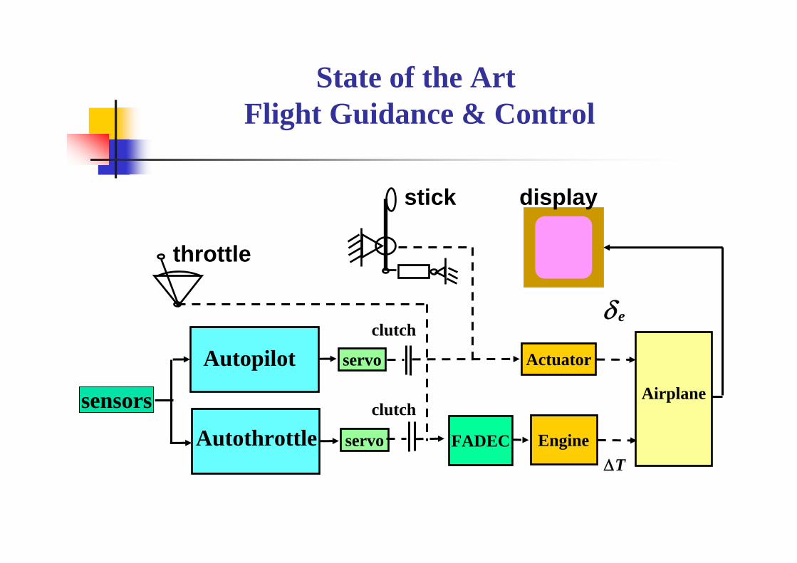
State of the Art Flight Guidance & Control
throttle
δe
displaystick
servo
Engine
Airplane
TΔ
sensors
clutch
clutch
servo
Autopilot
FADECAutothrottle
Actuator
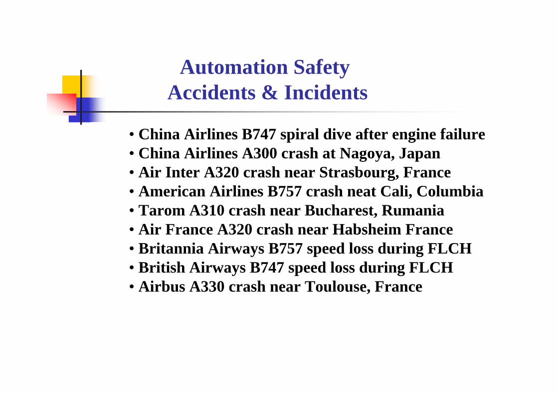
Automation Safety Accidents & Incidents
• China Airlines B747 spiral dive after engine failure• China Airlines A300 crash at Nagoya, Japan• Air Inter A320 crash near Strasbourg, France• American Airlines B757 crash neat Cali, Columbia• Tarom A310 crash near Bucharest, Rumania• Air France A320 crash near Habsheim France • Britannia Airways B757 speed loss during FLCH• British Airways B747 speed loss during FLCH• Airbus A330 crash near Toulouse, France
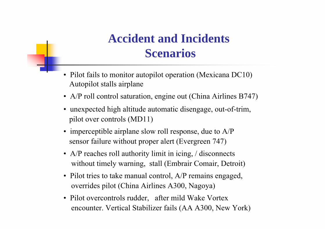
• Pilot fails to monitor autopilot operation (Mexicana DC10)Autopilot stalls airplane
• A/P roll control saturation, engine out (China Airlines B747)
• unexpected high altitude automatic disengage, out-of-trim, pilot over controls (MD11)
• imperceptible airplane slow roll response, due to A/P sensor failure without proper alert (Evergreen 747)
• A/P reaches roll authority limit in icing, / disconnects without timely warning, stall (Embrair Comair, Detroit)
• Pilot tries to take manual control, A/P remains engaged, overrides pilot (China Airlines A300, Nagoya)
• Pilot overcontrols rudder, after mild Wake Vortexencounter. Vertical Stabilizer fails (AA A300, New York)
Accident and Incidents Scenarios

Typical Transport AirplaneFlight Guidance & Control System
as many as 8 LRUs
Triple
FMS• Mission Planning• Navigation• Performance
Autothrottle
Yaw DamperDual
Single
Dual
• ThrustRating
• Thrust Limiting• Flare Retard
• highly complex designs• historically evolved subsystems• extensive functional overlap• operational inconsistencies• incomplete envelopeprotection
• SISO control• little or no standardization
• Altitude• Heading• V-Path• H-Path• Speed
• Vert. Spd
Autopilot
• Autoland• Envelope Protect.

• role and expectations of pilot in automated aircraft• automation - should not induce false sense of security• pilot expects basic operational safety
• crew difficulty of keeping abreast of automatic operations• operational complexities: current designs not pilot-like• situation awareness :
• mode annunciation /caution and warnings• recognizing / managing abnormal conditions
• predictability: when, how, why things happen• mixing manual & automatic can defeat basic safety features
• design• SISO control modes: can result in loss of control• poor man-machine interfaces• correct level of automation: keeping pilot “in the loop”
• adequacy of initial and recurrent training
Automation Safety Issues

Operational Complexity
• Who is in control? The pilot, FMS, autopilot, autothrottle?• too many overlapping systems, modes , sub modes
• what is the system doing, what will it do next?• crew confusion!
• inconsistent operations and performance:• different modes, different results: automation surprises!• complex mode logic, e.g. Flight Level Change, VNAV
• unsuitable man-machine interfaces,• e.g. attention/ procedure intensive CDU keyboard
• inadequate mode annunciation /caution and warnings• when should pilot intervene, or take over• pilots putting too much trust in low integrity single
channel designs, not aware their limitations

Design Complexity
• historic systems evolution has led to• new functions added-ons with each generation
• e.g. GLS on 737 NG: 11 LRUs involved!• old problems “solved” by new modes / submodes
• e.g. Flight Level Change, VNAV, Thrust modes • automation fragmentation into subsystems
• autopilot, autothrottle, FMS, SAS, FBW • each subsystem handled by different organization• design of each function approached as new problem
• SISO control : integration difficulties• modes / sub modes cobbled together by intractable mode logic
• mix of old and new technologies• digital hardware with analog architectures!
• no overall design & integration strategy!

Design Requirements “Creep”on a Recent AFCS Program
Successive Spec Revisions…..
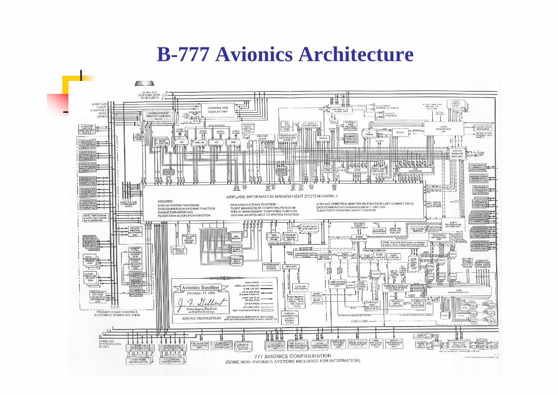
B-777 Avionics Architecture

Flight Guidance and Control Design Process
• 100 year evolution of systems & subsystems• more capabilities with each generation• most functions “Non-Flight Critical”
• only Autoland and manual control considered “Flight Critical”
• new technologies/ old control strategies • analog to digital / mechanical to FBW• introduction of Augmented Manual Control• Single Input / Single Output retained
• no certified Multi-Variable designs• Major Issues:
• outdated Requirements and Design Approaches

Single-Axis SISO Control
• Single axis SISO automatic control modes havebeen the standard since earliest days of automation
• It works…. most of the time, however….• stability and performance cannot be guaranteed:
• loss of control possible, e.g. vert path modes• full time pilot monitoring required!
•SISO control is root-cause of most automation complaints• single controller input not only changes intended variable, but also
causes unintended responses of other variables: • need other controller inputs to suppress unintended controlcoupling errors
• poor damping, high control activity• mode proliferation & complexities, operational inconsistencies and pilot confusion

BASIC AIRPLANE CHARACTERISTICS: THRUST AND DRAG AS FUNCTION OF SPEED
Trust,Drag
Speed
DragTrimSpeed
Power Setting
Thrust
Point of Neutral Stability
Front Side
BackSide
StallSpeed
Stable T P
UnstableTrim Point

• Generalized all-encompassing MIMO control strategy forall automatic and augmented manual modes
• up-front integration of functions• pitch/thrust control• roll/yaw control (including rudder) - inherent
• yaw damping /turn coordination• thrust asymmetry compensation
• improved failure detection, identification and isolation• envelope protection
• airspeed, normal load factor, angle of attack, roll angle
FUTURE SYSTEMS REQUIREMENTS

• large cost reductions, achievable through• reduced system complexity, less maintenance
• faster system development cycle• design reusability- lower risk• reduced customization• standard off-the-shelf hardware• less lab/flight testing
• reduction in pilot training need• automation safety improvements
FUTURE FG&C SYSTEMS DESIGN OBJECTIVES

FG&C• Airspeed/ Mach• Altitude/Vertical Spd• Heading/Track• Loc / GS, V-Nav / L-Nav• Envelope Protection• FBW Manual Mode
Tactical Automatic &FBW augmented manualControl Modes and Safety Functions
FMC
Flight planning• Navigation• Path Definition• Performance Predict.
StrategicAirline OperationsOriented FunctionsCDU
T-NAV V-NAV L-NAV
P-R-Y MANUAL
00340 .712
IAS MACH ALTHOLD
FPA TRACK HEADALTACQ
0.0 137 135
THRUST MANUAL
GA
24500 VARIABLEVAR
LOCGS
VMAX
VMIN
• Rational Function Partitioning
• No Function Overlap• Common Control Strategy• Simplified Reusable Design
Control TargetsMCP
Future FG&C System Architecture
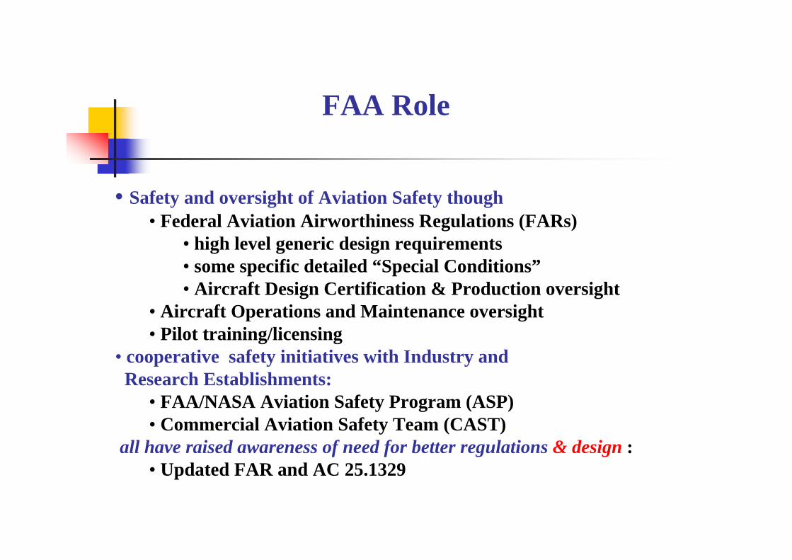
FAA Role
• Safety and oversight of Aviation Safety though• Federal Aviation Airworthiness Regulations (FARs)
• high level generic design requirements• some specific detailed “Special Conditions”• Aircraft Design Certification & Production oversight
• Aircraft Operations and Maintenance oversight • Pilot training/licensing
• cooperative safety initiatives with Industry and Research Establishments:
• FAA/NASA Aviation Safety Program (ASP)• Commercial Aviation Safety Team (CAST)
all have raised awareness of need for better regulations & design :• Updated FAR and AC 25.1329

Updated FAR and AC 25.1329
• Coverage: Autopilot, Autothrust and Flight Director (not FMS)• Key new requirements:
• Vertical Modes preferred operational characteristics• engage/disengage/ mode switching transients• warning/alert for autopilot and autothrottle disengage • manual override must not create unsafe condition
• significant override force should disconnect autopilot• speed envelope protection (as a minimum crew alert)• logical man-machine interfaces to minimize crew errorand confusion
• automatic trimming in opposition to pilot input prohibited• prevent “jack knifing” elevator/stabilizer • trim on elevator position, not stick force

Generalized Functionally Integrated Multi-Axes Control
• Automatic FG&C has contributed in a major way to flight safety
• Future FG&C systems can further enhance flight safety, operational effectiveness and reduce system costs through
• Generalized Multi-Input / Multi-Output (MIMO) control strategy• pilot-like control, used for all control modes
• automatic• augmented manual• envelope protection
• reduced mode complexity • fewer Up-Front integrated modes
• simpler more intuitive man-machine interfaces• Mode Control Panel (MCP)• advanced displays ( e.g. SVS Terrain, HITS, FPA symbology
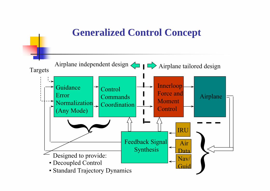
Generalized Control Concept
Targets
Feedback Signal Synthesis
Airplane
InnerloopForce and Moment Control
Nav/Guid
AirData
IRU
Guidance Error Normalization(Any Mode)
ControlCommands Coordination
Airplane tailored designAirplane independent design
• Decoupled Control• Standard Trajectory Dynamics
Designed to provide:

TECS/THCS Research Project
Need for safer/more effectively integrated FG&C system was recognized in late seventies during NASA TCV program
Identified Root Cause of most FG&C System Deficiencies Peace meal mode-by-mode systems evolutionSIS0 design
NASA /Boeing Research Program, initiated in 1979, resulted in Total Energy Control System (TECS)
Generalized energy based MIMO Flight Path & Speed Control Detailed system development & extensive Pilot-In-The-Loop simulator evaluations (1980-1985)Validated by Flight Test & In-flight demonstrations (1985)
Generalized integrated lateral directional control concept was developed under DARPA/Boeing Condor program (1985-1990), resulting in
Total Heading Control System (THCS)

Energy based Longitudinal Control
Speed
Altitude ThrustControl
ElevatorControl
Trim Point
• Responses to elevator and throttle are coupled in speed and altitude
• Pilots have learned through training todecouple flight path and speed control
• Current automatic control modes failto account for this control coupling:
its operation is like giving- throttle to one pilot to control speed- elevator to other pilot to control flight path
/gv+γ/gv−γ
• Elevator and thrust control are ~orthogonal
• Throttle controls Total Energy Rate:• Elevator controls Energy Distribution: }This Energy Strategy used to
achieve “pilot-like quality” in automatic control
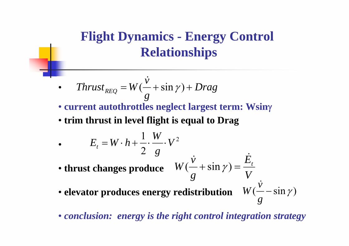
Flight Dynamics - Energy ControlRelationships
DraggvWThrustREQ ++= )sin( γ•
• current autothrottles neglect largest term: Wsinγ• trim thrust in level flight is equal to Drag
•
• thrust changes produce
• elevator produces energy redistribution
• conclusion: energy is the right control integration strategy
VE
gvW t=+ )sin( γ
2
21 V
gWhWEt ⋅⋅+⋅=
)sin( γ−gvW

Total Energy Control System (TECS)
• concept• thrust controls Total Energy requirement • elevator controls distribution of energy
• result: generalized multi-input / multi-output control strategy•speed /flight path mode errors are normalized intoenergy quantity, fed forward to throttle and elevator:
• provides decoupled command responses• consistent/energy efficient operation in all modes
• control priority when thrust limits:• generally speed control has priority• exception: glide slope / flare mode• Vmin/Vmax envelope always protected
• Vcmd limited to Vmin/Vmax
• control authority allocation: handles complex maneuvers
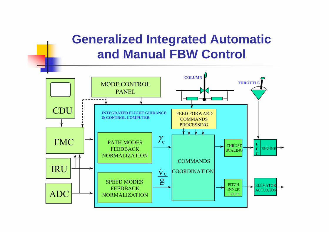
Generalized Integrated Automaticand Manual FBW Control
MODE CONTROLPANEL
FMC
IRU
CDU
THROTTLE
ELEVATORACTUATOR
ENGINEPATH MODES
FEEDBACKNORMALIZATION
SPEED MODES FEEDBACK
NORMALIZATION
COMMANDS
COORDINATION
FEED FORWARDCOMMANDS PROCESSING
THRUSTSCALING
PITCHINNERLOOP
INTEGRATED FLIGHT GUIDANCE& CONTROL COMPUTER
Cγ
gv C
COLUMN
.EEC
ADC

TECS Functional Architecture and Mode Hierarchy
Altitude
Glide Slope
Vert. Path
IAS
Mach
Time Nav
Flight pathAngle
FlareGo Around
Manual FBW
Vmax
Vmin
V
..Kh
Kv 1/g
V
RateLimit
RateLimit
Generalized Thrust and Elevator CommandsCoordination
v_cg
Tc
V
δec
Kv 1/g
Kv 1/g
energy control energy rate control
γcGlide Slope
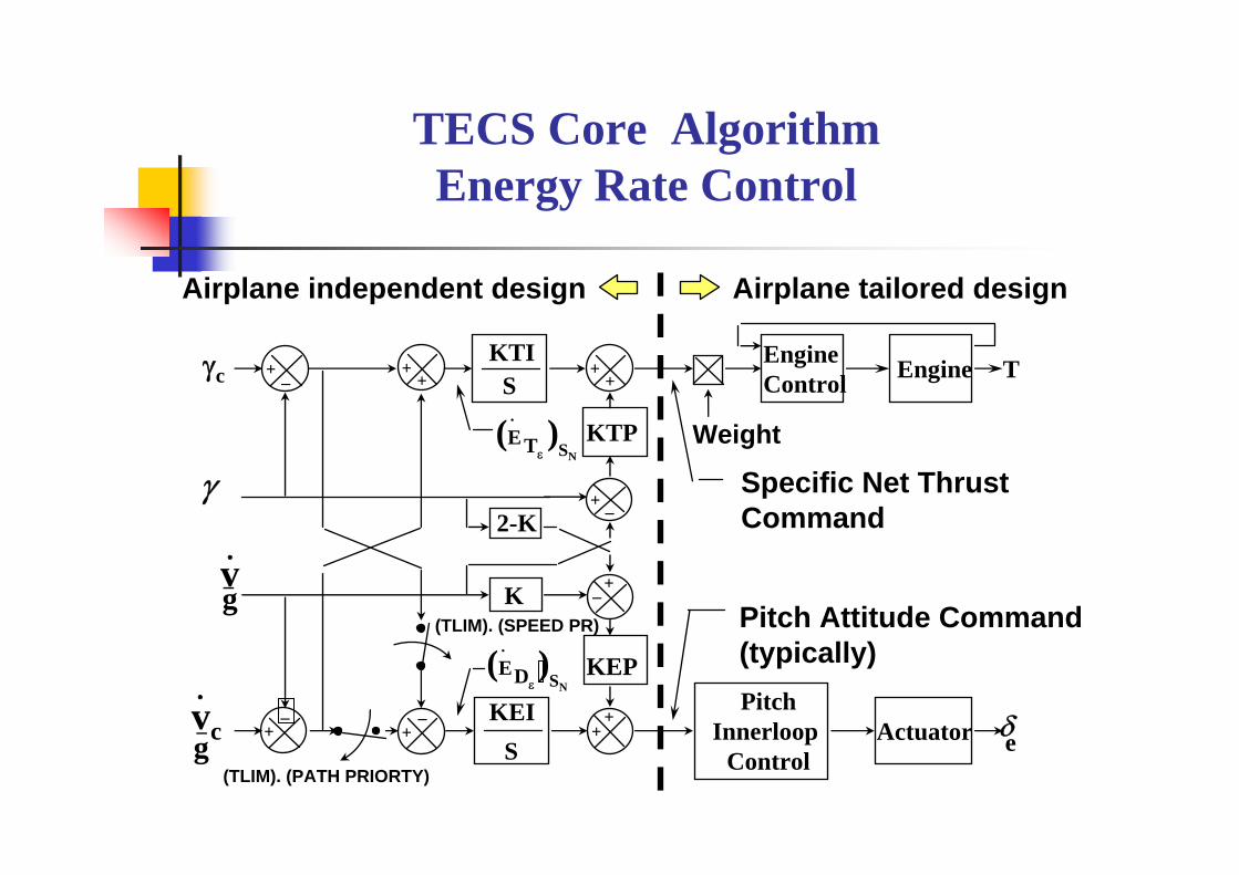
TECS Core Algorithm Energy Rate Control
EngineControl Engine
(TLIM). (PATH PRIORTY)
PitchInnerloop
ControlActuator
KTIS
KEIS
KTP
KEP
(TLIM). (SPEED PR)
2-K
K
+++ _
+_
+_ +
+
++
+
_
+
_
Weight
Airplane independent design Airplane tailored design
T
δe
γ
γc
v_g
Specific Net Thrust Command
Pitch Attitude Command(typically)
vc_g
(E )Dε SN
(E )Tε SN
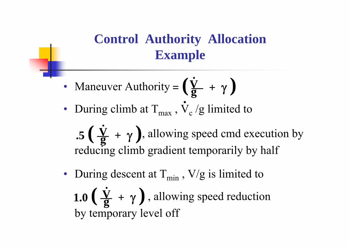
Control Authority AllocationExample
• Maneuver Authority
• During climb at Tmax , Vc /g limited to
, allowing speed cmd execution by reducing climb gradient temporarily by half
• During descent at Tmin , V/g is limited to
, allowing speed reduction by temporary level off
.5 ( — + γ ).Vg
1.0 ( — + γ ).Vg
= ( — + γ ).Vg.


Envelope Protection Functions
• Airspeed: keep between Vmin and Vmax, preferably at IAScmd• Solution can get very complex in traditional systems
• requires mode switching & crew alerting• Normal Load Factor (nz):
• automatic modes: |nz| < .1 for passenger comfort • FBW manual mode:
• 0 < nz < (nz)structural limit• low speed: nz < (nz) α-limit ; (nz) α-limit = (Ve/Vestall-1g)2
• Angle of Attack (α) limit: implicit if nz and Airspeed protected
• Bank Angle: bank limit depends on mode & flight condition• Sideslip (β) limiting: possible in some FBW manual designs


TECS/THCS Mode Control Panel Conceptwith Integrated ATC data link Functions

Advanced Displays

TECS Digital FCC / Throttle /FADECInterface Concept
Weight
FCC
Engine TFADEC
Engine TFADEC
IOEnginefailure logic
Tcmd
throttles
A to Dss
servo
No ofoperengines
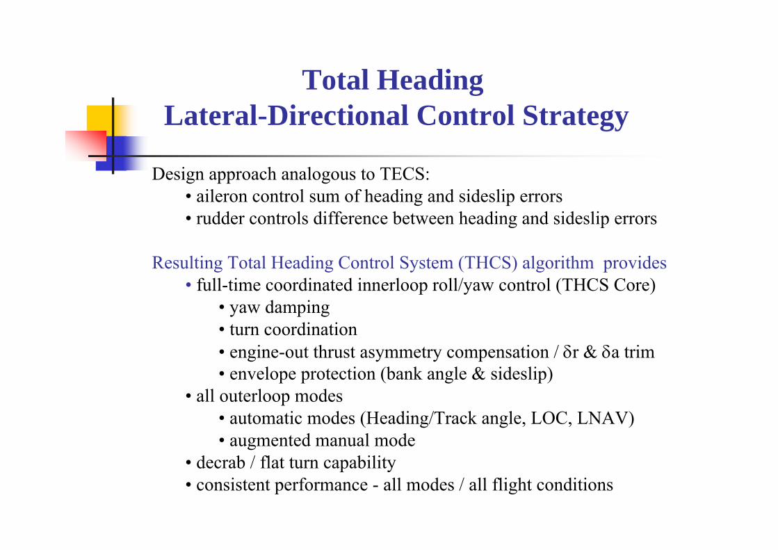
Total Heading Lateral-Directional Control Strategy
Design approach analogous to TECS:• aileron control sum of heading and sideslip errors• rudder controls difference between heading and sideslip errors
Resulting Total Heading Control System (THCS) algorithm provides • full-time coordinated innerloop roll/yaw control (THCS Core)
• yaw damping• turn coordination• engine-out thrust asymmetry compensation / δr & δa trim• envelope protection (bank angle & sideslip)
• all outerloop modes• automatic modes (Heading/Track angle, LOC, LNAV)• augmented manual mode
• decrab / flat turn capability• consistent performance - all modes / all flight conditions

THCS Functional Architecture and Mode Hierarchy
Roll AttitudeCommand
Generalized Roll Attitude and Yaw Rate CommandsCoordination
++
+ _+ _
+
_
+ _
+
_
Drift Angle Corr
Heading Command
L-Nav
Loc
Kψ
KβSideslipCommand
ψ
β
Ky
V
Yaw Rate Command
ψc
β c
Track Angle Command
ψ.
β.
..
Cross Track Deviation
Cross Track Velocity Cmd
Track AngleCommand

THCS Core Algorithm
+_
+
_
+
_
+
_
+
_
++
Kψ
Kβ
f(q )c
gVTrue
gVTrue
VTrueg
KRI
S
KYIS
Kφ
Kψ
K p+
_
pφ
ψ
ψ
+_
ψ
ψc
+_
β
βc
Airplane independent design Airplane tailored design
f(q )c
Actuator
Actuator
δa
δ r
φc
ψc
βc il
β
-1
-1
olcψ

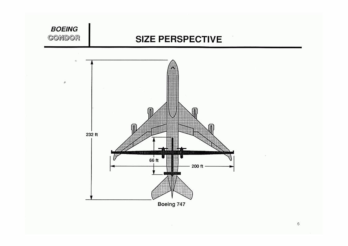
TECS and THCS Application on Condor


The Condor Team

Fly-By-Wire Design
• Definition: Airplane control concept whereby surfaces commanded through electrical wires
• Sought benefits:– Weight reduction – elimonation of mechanical systems – Drag reduction - Optimized aerodynamic performance by Relaxed
Static Stability – Standardized / improved handling qualities through SAS and CAS– Cost reductions
• Improved fuel economy• Reduced pilot training (common type rating)• Design commonality/design cycle time reduction• Reduced maintenance

FBW Functional Architecture
throttle
actuator
engine
δ e
Airplane
TΔFLIGHT CONTROL COMPUTER
display
Interface
trimup
downactuator δS
stick
feel system
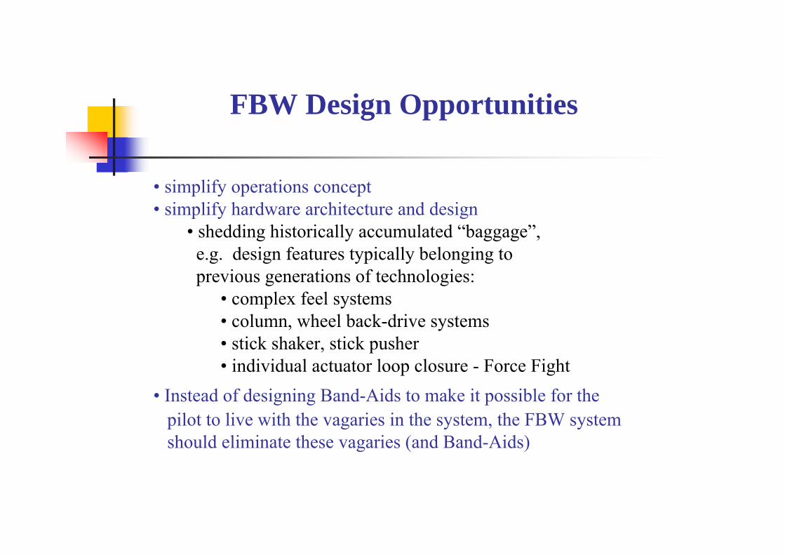
FBW Design Opportunities
• simplify operations concept• simplify hardware architecture and design
• shedding historically accumulated “baggage”,e.g. design features typically belonging to previous generations of technologies:
• complex feel systems• column, wheel back-drive systems• stick shaker, stick pusher • individual actuator loop closure - Force Fight
• Instead of designing Band-Aids to make it possible for the pilot to live with the vagaries in the system, the FBW systemshould eliminate these vagaries (and Band-Aids)

Major FBW Design Issues
• Controllers - Column & Wheel versus Sidestick• Feel system - Passive (e.g. spring) or Active (expensive !)• Control augmentation - Algorithm response type
• simple or none - little or no HQ advantages • stability/command – substantial benefits possible
• more complex/costly – many issues• Handling Qualities: what HQ, how best achieved
• envelope protection - major safety benefit !• Good design enhances pilot control authority
• mode changes takeoff/landing• Actuators: loop closure, e.g. central or remote loop closure• Redundancy architecture & component reliability

Handling Qualities
Definition: The conglomerate of characteristics and featuresthat facilitate the execution of a specific flight control task; includes display and feel characteristics
• good HQ requires design attributes appropriate to controltask (e.g. pitch attitude, FPA, or altitude control)
• each task has a finite time allotment or expectation forits completion (bandwidth requirement)
• direct control of “slow variables” requires special designattributes (e.g.FPA response augmentation & display)
• control harmony is achieved when the pilot can execute the task without undue stress and conscious effort

FBW ControlResponse Attributes for Good HQ
Desired Attributes:• “K/S”- like response• low response lag τ• correct sensitivity K• good damping• no overshoot• control harmony with other variables (θ, γ, nz)
• consistency betweenflight conditions
Time
ResponseTheta, FPA
Input δcol
Sensitivity (slope)Lag τ
KS
NOTE: signal δcol can serve as the cmd referenceKS
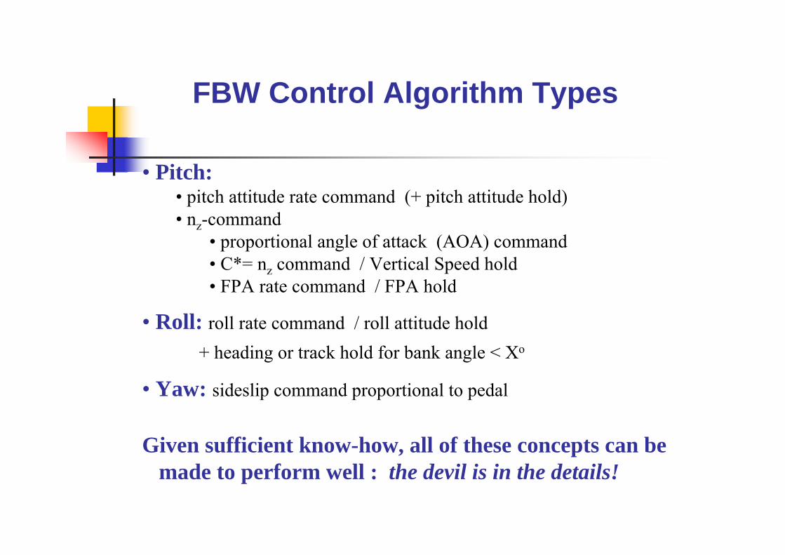
FBW Control Algorithm Types
• Pitch:• pitch attitude rate command (+ pitch attitude hold)• nz-command
• proportional angle of attack (AOA) command• C*= nz command / Vertical Speed hold• FPA rate command / FPA hold
• Roll: roll rate command / roll attitude hold+ heading or track hold for bank angle < Xo
• Yaw: sideslip command proportional to pedal
Given sufficient know-how, all of these concepts can bemade to perform well : the devil is in the details!

Basic FBW System ExampleEmbraer RJ-170 / DO-728 concept
stick
δe
Air Data
ActuatorActuatorElectronics
Pos sensor
ModularAvionics Units
Passive Feel
Default Gains
IRU
Airspeed Gain SchedAOA limiting
default
Autopilotservo
clutch
Autopilot cmds

Raytheon Low Cost GA FBW ConceptBonanza Flight Demo System
throttle
servo
engine
δeAirpl
TΔFCC
displaystick
DecoupledControl
Algorithm
sensor
sensor
clutch
clutch
servoVcmd
FPAcmd
• Stick commands proportional FPA; Throttle commands speed
Trim
Down
Up
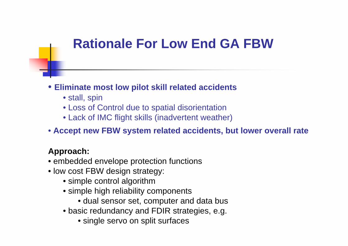
Rationale For Low End GA FBW
• Eliminate most low pilot skill related accidents• stall, spin• Loss of Control due to spatial disorientation• Lack of IMC flight skills (inadvertent weather)
• Accept new FBW system related accidents, but lower overall rate
Approach:• embedded envelope protection functions • low cost FBW design strategy:
• simple control algorithm • simple high reliability components
• dual sensor set, computer and data bus• basic redundancy and FDIR strategies, e.g.
• single servo on split surfaces

C* Design Concept
KS
KI
Sact.
engine
Vc o
g
throttle
+_
nz pilot
q++
stick
FFshaping
δe
ΔT
Airplane
ACE
FCC
comp
C*
C*cmd

C* Morphed into FPA rate cmd/hold
• responses identical to original C*, if gains are equivalent• fewer, simpler sensors• no pilot-out-of-the-loop control reference drift• still need extensive flight condition tuning• missing: integral control of γ-error
actu
engine
throttle
q
δ e
ΔTAirplane
Kq
KFF
Kθ
stick
θγ
cmdγ
γK
+
Prefilter
KI
S_ _+ _++

Augmented Manual Control Algorithm Design Objectives
• produce a generalized reusable design with• generic innerloop, shared with automatic modes• integral feedback control, to prevent response droop• final dynamics = classical airplane with ideal constant speed HQ:
• no undesirable response variability with flight condition • responses decoupled from airspeed - by autothrust• tracking of Control Reference when pilot out of the loop, e.g.
• pitch/roll attitude • flight path angle (preferred – minimizes workload)
1)S1}(τ)Sω/(2)S{(1/ω1)S1)(τS(τ
SK
1})S/ω(2ζ)S{(1/ω1)S(τ
SK
δθ
dSPSP22
SP
n2n1stick
SPSP22
SP
nstick
stick +++++
=++
+=
ζ
1)S1}(τ)S(1/K)SK(1/K)SKK{(1/K1)SKS(K
SK
δγ
2θI2
Iθ3
Iθq
FFI2
FFPstick
stick ++++++
=

Proposed Design Methodology for FBW Control Algorithms
Desired:• systematic/reliable process, producing desired results:• generalized/reusable design – minimal application & Flt Conditionadaptation
Approach:Step 1: Stability Augmentation using Static Inversion
eliminates flight condition dependencies, gain schedulesdefines basic SP innerloop characteristics: ω, ζ
Step 2: Add Integral Feedback loop“retrims” airplane - eliminates SS command response droop
Step 3: Add Command Augmentation Feed Forward Pathsshapes response to pilot control inputs, as desiredprovides “Hold” function for pilot established command

TECS FPA Control AlgorithmImplementation
stick
δe
AirplaneInvariant
Short Perioddesign 1
1
2+Sθτ
FPA
γ
KStick S1
γcγc.
Pitch ratePitch attitude
Feed ForwardControl Augmentation
θStatic Inversion
FPAFeedback Control
Augment.
Short PeriodDyn.
γ

Pilot Induced OscillationAvoidance
• pilot in the loop control requirements• bandwidth - appropriate to the task• response predictability
• linearity highly desirable• suitable controller forces & displacements • display(s) – appropriate to pilot task
• overall system design harmony - need• adequate control algorithm bandwidth• adequate actuator bandwidth and rate limits• correct controller sensitivity & authority
• matching of front-end and back-end design • display dynamics appropriate for pilot loop closure

Questions??