design of a flight stabilizer system and automatic control ... · pdf filedesign of a flight...
TRANSCRIPT

Design of a Flight Stabilizer System and
Automatic Control Using HIL Test Platform
Şeyma Akyürek, Gizem Sezin Özden, Emre Atlas, and Coşku Kasnakoğlu Electrical & Electronics Engineering, TOBB University of Economics & Technology, Ankara, Turkey
, sezin.ozden, emreatlas90, kasnakoglu}@gmail.com
Ünver Kaynak
Mechanical Engineering, TOBB University of Economics & Technology, Ankara, Turkey
Email: [email protected]
Abstract—In this paper a Hardware-In-the-Loop (HIL) test
platform is used to design a flight stabilization system for
Unmanned Aerial Vehicles (UAV). Controllers are first
designed and tested separately for lateral and longitudinal
axes using numerical simulations, and later these controllers
are merged on the HIL platform. It is observed that the
resulting controller successfully stabilizes the aircraft to
achieve straight and level flight.
Index Terms—UAV, autopilot, PID controller, Hardware-In-
the-Loop, flight control, SISO, MIMO
I. INTRODUCTION
Aeronautics has recently gained great importance in
both military and civil applications. The field of
Unmanned Air Vehicles (UAVs) is very broad, covering
myriad missions and system types [1]. Autopilot systems
are a major area of design for UAVs. These systems
perform autonomous flights. A flight mission can be
done without human input [2].
If an airplane is to remain in steady uniform flight, the
resultant forces as well as the resultant moment about the
center of gravity must both be equal to zero. An airplane
satisfying this requirement is said to be in a state of
equilibrium of flying at a trim condition [3].
In this paper we outline an approach based on a
hardware-in-the-loop platform for building a stabilizing
controller for UAVs. A suitable flight condition is
designed by MATLAB/Simulink environment simulation
to design a controller for UAVs. Flight control surfaces
are selected as the inputs of the system to hold the UAV
in this condition by trimming and linearizing using
MATLAB’s features. The next step is based on these
trim points of the system, where nonlinear flight
dynamical equations are linearized. There are several
types of controller can be used for UAVs but PID
controller is preferred and designed due its simplicity.
Manuscript received June 1, 2015; revised October 22, 2015.
Both manual calibration and MATLAB’s automated
design tools are used to determine the PID coefficients.
II. DESIGN STAGES
A. Controller Design A general treatment of the stability and control of
airplanes requires a study of the dynamics of flight [4].
Much useful information can be obtained, however, from
a more limited view, in which we consider not the motion
of the airplane, but only its equilibrium states. This is the
approach in what is commonly known as static stability
and control analysis [4].
Elevators and ailerons are flight control surfaces.
Elevators are surfaces on the tailplane (the horizontal part
of the tail assembly). While the entire tailplane surface
helps stabilize the aircraft during flight, the elevators
apply pitch by angling the trailing (rear) edge of the
tailplane up or down. Ailerons are surfaces on the outer,
trailing edge of each wing. They angle in opposite
directions to waggle the wings up and down or roll the
aircraft about its nose -tail axis. If you apply stick left or
right, one wing's aileron angles down and the other
angles up. This rolls one wing up and forces the other
wing down, effectively rolling the airplane [5].
Figure 1. Flight control surfaces on airliner [6].
1) Elevator-Theta control
The number and type of aerodynamic surfaces to be
controlled changes with aircraft category [6]. Fig. 1
shows the classic layout for a conventional airliner [6].
Aircraft have a number of different control surfaces:
77
International Journal of Mechanical Engineering and Robotics Research Vol. 5, No. 1, January 2016
doi: 10.18178/ijmerr.5.1.77-81
Email: { seymaakyurek
© 2016 Int. J. Mech. Eng. Rob. Res.

those indicated in red form the primary flight control, i.e.
pitch, roll and yaw control, basically obtained by
deflection of elevators, ailerons and rudder (and
combinations of them); those indicated in blue form the
secondary flight control; high-lift and lift-dump devices,
airbrakes, tail trimming, et al. [6].
Figure 2. The Simulink Model for SISO system.
Elevator angle is given as an input to the Simulink
model and theta angle is as an output. Firstly, Airlib
library in MATLAB is used for the aircraft dynamic
model. Cessna 172 flight model’s aerodynamic
derivatives are followed up. By using this aircraft model
a Simulink stucture is established. It can be seen in Fig. 2.
Determining the cruise speed and altitude condition,
trimming and linearization is obtained.
Figure 3. Theta output and elevator input step responses for the PID controller
the applied controller.
After linearization based on the operation point and
system’s minimal implementation is calculated, first step
was designing the PID controller by MATLAB sisotool.
Closed loop step response provided by PID controller
and the input which is applied are shown in Fig. 3. Also
it can be seen the input is reasonable.
PID control structure is built for supported flight mode
applied to the Simulink model’s input which is the
change of the elevator angle is shown in the Fig. 4. The
output of the system theta angle is shown in the Fig. 5.
Designed controller’s impact of the other angles can be
seen in the Fig. 5. It can be seen that the psi and phi
angles are not affected from the controller and remained
around zero.0.
Figure 5. Changes of psi, theta and phi as results of the applied controller.
2) Aileron phi controller
Aileron is the control surface which operates the
rolling of the UAV. This surface is the input of the
MATLAB model. The output is the phi angle which is
the rolling angle.
After linearization based on the operation point and
obtained system’s minimal implementation and PID
controller’s transfer function is calculated by MATLAB
sisotool. Derivative filter is used to create a more
resistant against noises and more realistic D parameter.
Closed loop step response provided by PID controller
and the input which is applied are shown in Fig. 6. Also
it can be seen the input and output are reasonable.
Figure 6. Phi output and aileron input step responses for the PID controller
78
International Journal of Mechanical Engineering and Robotics Research Vol. 5, No. 1, January 2016
Figure 4. Changes of elevator, aileron, rudder and throttle as results of
© 2016 Int. J. Mech. Eng. Rob. Res.
79
International Journal of Mechanical Engineering and Robotics Research Vol. 5, No. 1, January 2016
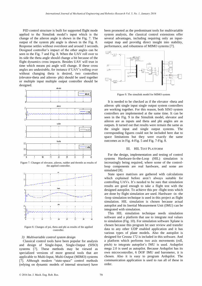
PID control structure is built for supported flight mode
applied to the Simulink model’s input which is the
change of the aileron angle is shown in the Fig. 7. The
output of the system phi angle is shown in the Fig. 8.
Response settles without overshoot and around 3 seconds.
Designed controller’s impact of the other angles can be
seen in the Fig. 7 and Fig. 8. When the UAV roll over to
its side the theta angle should change a bit because of the
flight dynamics cross impacts. Besides UAV will trun in
time which means psi angle will change. If these cross
angles are undesirable, for instance if UAV’s rolling over
without changing theta is desired, two controllers
(elevator-theta and aileron- phi) should be used together
or multiple input multiple output controller should be
designed.
Figure 7. Changes of elevator, aileron, rudder and throttle as results of the applied controller.
Figure 8. Changes of psi, theta and phi as results of the applied controller.
3) Multivariable control system design
Classical control tools have been popular for analysis
and design of Single-Input, Single-Output (SISO)
systems [7]. These methods may be viewed as
specialized versions of more general tools that are
applicable to Multi-Input, Multi-Output (MIMO) systems
[7]. Although modern “state-space” control methods
(relying on dynamic models of internal structure) have
been promoted as the predominant tools for multivariable
system analysis, the classical control extensions offer
several advantages, including requiring only an input-
output map and providig direct insight into stability,
performance, and robustness of MIMO systems [7].
Figure 9. The simulink model for MIMO system
It is needed to be checked as if the elevator -theta and
aileron -phi single input single output system controllers
are working together. For this reason, both SISO system
controllers are implemented at the same time. It can be
seen in the Fig. 9 in the Simulink model, elevator and
aileron are as inputs and theta and phi angles are as
outputs. It turned out that results were remain the same as
the single input and single output systems. The
corresponding figures could not be included here due to
space limitations but they were exactly the same
outcomes as in Fig. 4-Fig. 5 and Fig. 7-Fig. 8.
III. HIL TEST PLATFORM
For the design, implementation and testing of control
systems Hardware-In-the-Loop (HIL) simulation is
increasingly being required, where some of the control-
loop components are real hardware, and some are
simulated [8].
State space matrixes are gathered with calculations
which explained before aren’t always suitable for
controlling UAVs. It’s needed to be sure that simulation
results are good enough to take a flight test with the
designed autopilot. To achieve this pre -flight tests which
are done by flight simulation are used. Hardware -in -the
-loop simulation technique is used in this project as flight
simulation. HIL simulation is chosen because actual
autopilot and its Inertial Measurement Unit (IMU) can be
integrated with simulation.
This HIL simulation technique needs simulation
software and a platform that use to integrate real values
to simulation (Fig. 10). For simulation software Xplane is
chosen because this program let user review and transfer
data to any other UDP enabled application and it has
various types of plane models. Also the autopilot is
designed for Cessna 172 is included in this software. And
a platform which performs two axis movements (roll,
pitch) to integrate autopilot’s IMU is used. Ardupilot
mega 2.0 is used as autopilot. Because Ardupilot has its
own microcontroller, 6 DOF IMU and barometer, it is
chosen. Also it is easy to program Ardupilot. The
communication application is used to run all of these in
order.
© 2016 Int. J. Mech. Eng. Rob. Res.

80
International Journal of Mechanical Engineering and Robotics Research Vol. 5, No. 1, January 2016
Figure 10. HIL test platform and xplane simulations
HIL simulation performs as follows. Plane fly in the
Xplane generate roll and pitch angle values. These values
send to UDP port and communication application read
listens to Xplane’s UDP send data port, captures datasets,
distinguishes headers from data and sends angle bytes to
the platform’s microcontroller unit over serial port.
Platform’s microcontroller reads these values as
reference values for pitch axis PID and yaw axis PID.
Platform output and PID inputs are obtained by reading
encoders which are connected to motors’ shafts. Then
each PID controller calculates their output and drives
related motors which are individually connected to
separate control surfaces. That surface is placed to
desired angle. Therefore autopilot can be put over this
platform and can operate on its own. Also transmitter and
receiver are needed to give command to autopilot.
Autopilot calculates new values for aileron and elevator
according to given command and send them to serial port.
The communication applications read them and convert
them to messages Xplane can understand and write to
UDP port which Xplane is listening. Xplane reads these
values and actuates elevator and aileron according to
these values. And plane state is changed based on these
changes, new angle values are occurred.
Figure 11. Pitch axes stabilization results
Stabilizer is the first step of designing autopilot to test
it at stabilizing mode. Reliable autopilot matrixes have
been chosen after tests are made. Selected autopilot’s
results are shown in Fig. 11 and Fig. 12..
Figure 12. Roll axes stabilization results
In Fig. 11 and Fig. 12 the autopilot created runs in
stabilizer mode. In this mode it is possible to do
maneuvers like rolls and loops but if the sticks were
released then autopilot will level the plane. It can be seen
that the plane is levelled when maneuvers were done in
the Fig. 12. Maneuvers were done for pitch angle at 12th
to 14th seconds of simulations and levelled at around
17th seconds. Maneuver was done for roll angle around
16th second of simulation and levelled around 17th
second then another maneuver was done around 19th
second of simulation and levelled around 2 seconds of
simulations. Other times stabilizer mode of autopilot was
not been active.
IV. CONCLUSION AND FUTURE WORK
In this paper we outlined the design of elevator and
aileron stabilizer for UAVs and using data obtained from
Xplane simulation. These data are processed by a system
identification process utilizing MATLAB and a
dynamically model of the aileron and elevator behaviors
are obtained. These models are used to construct PID
controllers for these surfaces and hardware in the loop
simulations using a custom 3 degree of freedom moving
platform confirm that the designed controllers
successfully.
In future work surface loss scenarios are considered
and to eliminate the impact of these losses controllers
will be developed based on this study.
ACKNOWLEDGEMENTS
The authors would like to thank the Scientific and
Technological Research Council of Turkey (TÜBİTAK)
for supporting this work under project number 113E581.
REFERENCES
[1] J. Gundlach, Designing Unmanned Aircraft Systems: A
Comprehensive Approach, Virginia: AIAA Education Series,
2012. [2] H. Korkmaz, O. B. Ertin, C. Kasnakoglu, and Ü. Kaynak, “Design
of a flight stabilizer system for a small fixed wing unmanned
aerial vehicle using system identification,” Advances in Control and Automation Theory for Transportation Applications,
September 16-17, 2013.
© 2016 Int. J. Mech. Eng. Rob. Res.
81
International Journal of Mechanical Engineering and Robotics Research Vol. 5, No. 1, January 2016
[3] R. C. Nelson, Flight Stability and Automatic Control, Second Ed.,
McGRAW-HILL International Editions: Aerospace Science &
Technology Series, 1998.
[4] B. Etkin and L. D. Reid, Dynamics of Flight Stability and Control Third ed., Hamilton Printing Company, 1995.
[5] The Basics of Flight. [Online]. Available:
http://www.aviastar.org/theory/basics_of_flight/control.html [6] Aircraft Systems–Lecture Notes–Chapter 6-Flight Control System,
Polytechnic of Milan. [Online]. Available:
www.aero.polimit.it/~l050263/bacheca/Dispense_EN/06w-FligCont.pdf
[7] M. L. Nagurka and T. R. Kurfess, New Design Paradigms for
MIMO Control System Synthesis, Carnegie Mellon University Engineering Design Research Center, 1991.
[8] R. Isermann, J. Schaffnit, and S. Sinsel, “Hardware-in-the-loop
simulation for the design and testing of engineering control systems,” Control Engineering Practice, vol. 7, no. 5, pp. 643-653,
May 1999.
Seyma Akyurek is currently a master student
at the Electrical & Electronics Engineering
Department, TOBB University of Economics & Technology, Ankara, Turkey. She received
the BSc degree in Electrical & Electronics
Engineering in 2014 from the TOBB University of Economics & Technology,
Ankara, Turkey. Control systems and
autopilot design for UAVs are her current research areas.
Gizem Sezin Özden is currently MSc
student at the Electric and Electrical
Engineering Department, TOBB ETU, Ankara, Turkey. She received the both
Mecatronics Engineering and the Electric and
Electrical Engineering in 2014 from TOBB ETU, Ankara, Turkey. Control systems and
UAVs are her current research areas.
Emre Atlas is currently a master degree
student at the Electric & Electronics
Engineering Department, TOBB University
of Economics and Technology, Ankara, Turkey. He received the BSc degree in
Electric & Electronics Engineering in 2014
from TOBB University of Economics and Technology, Ankara, Turkey. Control
systems and autopilot design for UAVs are
his current research areas.
Coşku Kasnakoğlu
obtained B.S. degrees from the Department of Electrical and
Electronics Engineering and the Department
of Computer Engineering at the Middle East Technical University (METU), Ankara,
Turkey in 2000. He obtained his M.S. and
Ph.D. degrees from the Department of Electrical and Computer Engineering at the
Ohio State University (OSU), Columbus, Ohio, USA in 2003 and 2007. He is currently
an associate professor in the Department of
Electrical and Electronics Engineering at TOBB University of Economics and Technology in Ankara, Turkey. Dr. Kasnakoglu's
current research interests include nonlinear control, flow control,
unmanned air vehicles, dynamical modeling, adaptive control and linear parameter varying systems.
Ünver Kaynak obtained B.S. and M.S.
degrees from Istanbul Technical University,
Istanbul, Turkey in 1979 and 1981, and M.S and Ph.D. degrees from Stanford University,
CA, USA in 1984 and 1986. He is currently a
professor in the Department of Mechanical Engineering at TOBB University of
Economics and Technology in Ankara, Turkey. Dr. Kaynak’s current research
interests include fluid mechanics,
aerodynamics, transitional flows and unmanned air vehicles.
© 2016 Int. J. Mech. Eng. Rob. Res.