gemini gv6 hardware installation guide - parker hannifin · rtn rela y co m r elay n.o. ......
TRANSCRIPT

DA
TA B
US
OU
TD
ATA
BU
S IN
Servo
+24VDC
24V RTN
RELAY COM
RELAY N.O.
RS
-232/485
U
V
W
VBUS+
VBUS-
L2/N
L1
COMPUMOTOR DR
IVE
I/OM
OTO
R FE
ED
BA
CK
GV-U3/6/12
MO
TOR
WA
RN
ING
: Haz
ardo
us v
olta
ge m
ay e
xist
for
up to
30
sec
onds
afte
r po
wer
is r
emov
ed.
DA
TA B
US
OU
TD
ATA
BU
S IN
GV-H20
SERVO
U
V
W
VBUS+
VBUS–
L3
L2
L1
MO
TOR
WA
RN
ING
: Haz
ardo
us v
olta
ge m
ay e
xist
for
up to
30
sec
onds
afte
r po
wer
is r
emov
ed.
+24VDC
24V RTN
RELAY COM
RELAY N.O.
COMPUMOTOR DR
IVE
I/OM
OTO
R FE
ED
BA
CK
RS
-232/485
Compumotor
GEMINI
H40
U
V
W
VBUS+
VBUS-
L3
L2
L1
SERVO
MO
TOR
MA
INS
3Ø
240
VA
C
RS
-232/485
WARNING: Hazardous voltage may
to 8 minutes after power
+24V DC
24V Rtn
RELAY COM
RELAY N.O.
Effective: February 1, 2002
p/n 88-018364-01 B
Gemini GV6 HardwareInstallation Guide
Automation
GV
6-H
40 D
rive
show
n
GV
6-H
20 D
rive
show
n
GV
6-U
3 D
rive
show
n
Gemini GV6 SeriesDigital Servo Controller/Drives

North America and Asia:Compumotor Division of Parker Hannifin5500 Business Park DriveRohnert Park, CA 94928Telephone: (800) 358-9070 or (707) 584-7558Fax: (707) 584-3793FaxBack: (800) 936-6939 or (707) 586-8586e-mail: [email protected]: http://www.compumotor.com
Europe (non-German speaking):Parker Digiplan21 Balena ClosePoole, DorsetEngland BH17 7DXTelephone: +44 (0)1202 69 9000Fax: +44 (0)1202 69 5750
Germany, Austria, Switzerland:HAUSER Elektronik GmbHPostfach: 77607-1720Robert-Bosch-Str. 22 D-77656 OffenburgTelephone: +49 (0)781 509-0Fax: +49 (0)781 509-176
Technical Assistance Contact your local automation technology center (ATC) or distributor, or ...
Automation [email protected]
Technical Support Email
Gemini Series products and the information in this user guide are the proprietary property of Parker Hannifin Corporation or its licensers, and may not be copied, disclosed, or used for any purpose not expressly authorized by the owner thereof.
Since Parker Hannifin constantly strives to improve all of its products, we reserve the right to change this user guide and software and hardware mentioned therein at any time without notice.
In no event will the provider of the equipment be liable for any incidental, consequential, or special damages of any kind or nature whatsoever, including but not limited to lost profits arising from or in any way connected with the use of the equipment or this user guide.
© 2002, Parker Hannifin CorporationAll Rights Reserved
User Information
WARNINGGemini Series products are used to control electrical and mechanical components of motion control systems. You should test your motion system for safety under all potential conditions. Failure to do so can result in damage to equipment and/or serious injury to personnel.
! !
Motion Planner and Pocket Motion Planner are trademarks of Parker Hannifin Corporation.Microsoft and MS-DOS are registered trademarks, and Windows, Visual Basic, and Visual C++ are trademarks of Microsoft Corporation.

Preface 3
Table of Contents
CHAPTER 1 – INTRODUCTION .................................................................................................................................. 7Gemini Products—Overview .............................................................................................................................................. 8Compatible Compumotor Products ................................................................................................................................... 10
CHAPTER 2 – INSTALLATION ..................................................................................................................................11Checking Your Shipment ................................................................................................................................................... 12“Express Setup” Overview ................................................................................................................................................ 12Step 1 – Connecting the Motor .......................................................................................................................................... 14Step 2 – Connecting AC Power ......................................................................................................................................... 16Step 3 – Configuring the Drive .......................................................................................................................................... 18Step 4 – Verifying Correct System Installation ................................................................................................................. 20What’s Next? ..................................................................................................................................................................... 21
CHAPTER 3 – CONFIGURATION ..............................................................................................................................23Configuration ..................................................................................................................................................................... 24Tuning Procedures ............................................................................................................................................................. 28
Position Mode Tuning ................................................................................................................................................ 28Filter Adjustments ...................................................................................................................................................... 30
CHAPTER 4 – SPECIAL FEATURES......................................................................................................................... 33Relay Connections (optional) ............................................................................................................................................ 34+24VDC “Keep Alive” Power Connections (optional) .................................................................................................... 34Multiple Drive Installations (optional) .............................................................................................................................. 35Regeneration Protection .................................................................................................................................................... 36Aligning the Resolver (optional) ....................................................................................................................................... 40RS-232/485 Communications ........................................................................................................................................... 42
Establishing Communications .................................................................................................................................... 42Configuring the Serial Port ......................................................................................................................................... 42RS-232 Communications ........................................................................................................................................... 43RS-232 Daisy-Chaining ............................................................................................................................................. 43RS-485 Communications ........................................................................................................................................... 45RS-485 Multi-Drop .................................................................................................................................................... 46
Updating the Drive’s Operating System ............................................................................................................................ 46
CHAPTER 5 – TROUBLESHOOTING ......................................................................................................................... 47
APPENDIX A – SPECIFICATIONS .............................................................................................................................55Power Specifications ......................................................................................................................................................... 56Interface/Communication .................................................................................................................................................. 57Inputs and Outputs ............................................................................................................................................................. 58Feedback Devices .............................................................................................................................................................. 64Dimensions ........................................................................................................................................................................ 67Protective Circuits ............................................................................................................................................................. 72Cable Specifications .......................................................................................................................................................... 74
APPENDIX B – USING NON-COMPUMOTOR MOTORS .................................................................................................77
APPENDIX C – REGULATORY COMPLIANCE: UL AND CE ...........................................................................................81
INDEX ................................................................................................................................................................89

4 Gemini GV6 Hardware Installation Guide
Product Type : Gemini Family of Drives, GV6-nnnn
Including, but not limited to :
GV6-L3n, GV6-U3n, GV6-U6n, GV6-U12n,GV6-H20n, GV6-H40nGPDM
When installed in accordance with this installation guide, the above products havebeen demonstrated to be in compliance with the requirements of directives
• 89/336/EEC Electromagnetic Compatibility Directiveas amended by Directive 92/31/EEC
These products are intended for use in Commercial, Light Industrial and IndustrialEnvironments as defined in the relevant EMC standards.
These products are compliant with the Low Voltage Directive.
• 73/23/EEC Low Voltage Directive
• 93/68/EEC CE Marking Directive
Symbols:
Protective Earth Connection
Earth (Ground) Terminal
Shield, Frame, or Chassis Terminal
Caution, Risk of Electrical Shock
Caution, Refer to Accompanying Documentation

Preface 5
Change Summary
Gemini GV6 Hardware Installation Guide
Revision BFebruary 1, 2002
The following is a summary of the primary technical changes to this documentsince the previous version was released.
This document, part number 88-018364-01B, supersedes 88-018364-01A.
GV6-H40 Drive Added to Gemini Product LineNEW: Information about the Gemini GV6-H40 Drive has been added throughoutthis Hardware Installation Guide.
+24VDC Power Input – Current Specification (page 35)
CHANGE: The input current specification has been changed from 500 mAmaximum to 500 mA minimum required from your power supply.
Connecting V Bus±: Fuse Each Drive (page 36)
CLARIFICATION: When connecting two or more drives through their V Bus±terminals, fuse the AC input lines of each drive, as the drawing labeled Sharingthe Power Bus now shows.
TASX, Bit 5 – Resolver Failure (page 50)
CHANGE: The TASX command’s Bit 5 indicates resolver failure (not encoderfailure).
Analog Input Added (page 63)
NEW: An analog input has been added to the DRIVE I/O connector, on pins 23and 24 of the 50 pin connector.
Soldercup Connectors Specified (page 58 & 64)
NEW: Mating soldercup connectors and backshells are specified for the 50 pinDRIVE I/O connector and the 26 pin MOTOR FEEDBACK connector.
Panel Layout – Vertical Clearance for GV6-H20 (page 71)
CHANGE: Allow 2 inches (50.8 mm) below a GV6-H20 drive. If you mountanother drive above a GV6-H20, allow at least 4 inches (100 mm) verticalclearance above the GV6-H20; allow 6 inches (150 mm) if operating at full power.
Non-CE Cables (pages 74 – 75)
NEW: Compumotor now offers non-CE cables.

6 Gemini GV6 Hardware Installation Guide
Hall Sensors – Configuration and Troubleshooting (page 78)
NEW: Information about configuring and troubleshooting Hall sensors has beenadded to Appendix B Using Non-Compumotor Motors.
Ferrite Absorbers Recommended for GV6-H20 (page 84)
CHANGE: For increased product immunity and reduced product emissions,particularly with large servo motors, we now recommend that you install two clip-on ferrite absorbers.

Chapter 1 – Introduction 7
1Introduction
IN THIS CHAPTER
• Gemini Product Overview
• Compatible Compumotor Products
C H A P T E R O N E

8 Gemini GV6 Hardware Installation Guide
Gemini Products—Overview
The Gemini Series is a family of high performance digital drives. The familycontains drives for both stepper and servo motors. With many models and optionsavailable, the user can choose the precise level of power and control for theapplication’s motion requirements.
Gemini Product Descriptions
Gemini GT and GVGemini GT Stepper Drives and GV Servo Drives are the basic Gemini products.They are controlled with standard command interfaces of step/direction or ±10V,and can be used with standard indexers or controllers.
The drives are configured over RS232/485 with either Motion Planner on apersonal computer (PC), or Pocket Motion Planner on a palm PC. Many advancedfeatures are standard in the drives, such as sensorless stall detect and ABS damp-ing in the GT, and digital tuning and notch filters in the GV.
Gemini GT6 and GV6The Gemini GT6 and GV6 are controller/drives available with several differentprogramming modes. These drives have basic motion control and sequencingcapabilities, and can be used in distributed control applications. By using optionalplug-in cards, they can be equipped with interfaces for Profibus or DeviceNet.
The GT6 and GV6 are configured and programmed over RS232/485, either withMotion Planner on a PC, or Pocket Motion Planner on a palm PC.
Gemini GT6K and GV6KThe GT6K and GV6K are single axis packaged controller/drives in the Geminifamily that offer full 6K Series controller functionality and programmability forcomplex distributed control applications. Key features include: complex programcapabilities such as math, variables, and logic control; flexible and expandableserial I/O modules; and Ethernet compatibility for PC bus access. The userprograms these devices over an RS232/485 communication port or Ethernet; asecond port is available for use with a full-time operator interface.

Chapter 1 – Introduction 9
Gemini Product NamesThe following table lists the meanings of letters and numbers in Gemini productnames. Notice that “T” is associated with step motor products (“sTep”), and “V” isassociated with servo motor products (“serVo”).
Control Level:Step Motor Drives Servo Motor Drivesand Controller/Drives and Controller/Drives
GT Step Motor Drive GV Servo Motor Drive
GT6 6000-based Step Motor Controller GV6 6000-based Servo Controller
GT6K 6K-based Step Motor Controller GV6K 6K-based Servo Controller
Power Level:Step Motor Drives and Controller Drives
L5 120VAC, 5A at 170VDC
L8 120VAC, 8A at 170VDC
Servo Motor Drives and Controller/Drives
L3 120VAC, 3A continuous, 7.5A peak at 170VDC
U3 120/240VAC, single phase, 3A continuous, 7.5A peak at 170/340VDC
U6 120/240VAC, single phase, 6A continuous, 15A peak at 170/340VDC
U12 120/240VAC, single phase, 12A continuous, 30A peak at 170/340VDC
H20 208/240VAC, three phase, 20A continuous, 50A peak at 294/340VDC (single phase: 16A continuous, 50A peak at 294/340VDC)
H40 208/240VAC, three phase, 40A continuous, 100A peak at 294/340VDC
Amperage values represent continuous current, peak of the sine wave.
“L” = “Low” voltage input (120VAC)
“U” = “Universal” voltage input (120/240VAC)
“H” = “High” voltage input (208/240VAC)
Options:Data Bus (-db) Option (for GT6 and GV6 only):
DN DeviceNet
PB Profibus
Feedback (-fb) Option (for Servos only):
E Encoder/Hall
R Resolver
Ship Kit Options:
NK No Kit
Format:
GeminiV or T
6, 6K or BlankL, H or U
GV = 3, 6, 12, 20, 40GT = 5, 8
E, R or BlankDN, PB or Blank
-NK or Blank
Drive:Type:
Control:Input Voltage Level:
Output Motor Current:
Feedback Option:Data Bus:
Ship Kit Option:
G V 6 - L 3 E - P B - N K
Format Example

10 Gemini GV6 Hardware Installation Guide
Compatible Compumotor Products
GT-nn Stepper 6K or other Compumotor indexer
GV-nnn Servo ±10V mode: 6K or other Compumotor controller
Step/Direction mode: 6K or other Compumotor indexer
Software Motion Planner
Pocket Motion Planner (version 1.2 or higher)
Note: Gemini drives are not compatible with ASCII communicationprograms such as Motion Architect or X Language software.
Cables, Motors, etc.: See list at beginning of Chapter 2 Installation, in Appendix ASpecifications, and in the separate Gemini Motor ReferenceManual.
User Guides
The following items ship with the drive:
Gemini Quick Start Guide
Gemini Hardware Installation Guide
Gemini Programmer's Reference
Gemini Motor Reference Manual
Motion Planner CD-ROM
You can also order the drive only, with none of the above items. Specifythe -NK option (“No Kit”).
Motor InformationInformation about Compumotor motors is in the separate Gemini Motor ReferenceManual.

Chapter 2 – Installation 11
2Installation
IN THIS CHAPTER
• Checking Your Shipment
• Express Setup
C H A P T E R T W O

12 Gemini GV6 Hardware Installation Guide
Checking Your Shipment
Inspect your shipment carefully. You should have received one or more of thefollowing:
Gemini DrivesGV6-L3n (“n” can be E (for encoder) or R (for resolver))
GV6-U3n
GV6-U6n
GV6-U12n
GV6-H20n
GV6-H40n
Ship Kit ItemsThe following ship with the drive:
Part Part Number
Gemini GV6 Quick Reference Guide 88-018365-01
Gemini GV6 Hardware Installation Guide 88-018364-01
Gemini Programmer's Reference 88-017778-01
Gemini Motor Reference Manual 88-017790-01
Motion Planner CD-ROM 95-017633-01
Options and AccessoriesYou may have ordered one or more of the following options or accessories.
Part Part Number
GPDM Gemini Power Dissipation Module GPDM
Drive Only (no accompanying manuals) -NK
Cables: various cables, breakout modules, etc., are available. See Appendix A Specifica-tions for cable and accessory information.
Cable clamps, EMC filters, ferrites, etc., are available. See Appendix C RegulatoryCompliance for part numbers and more information.
MotorsYou may have ordered a motor from one of the following families of Compumotormotors:
SM Series BE Series J Series
NeoMetric Series M Series Linear Series
“Express Setup” Overview
This chapter gives instructions for performing an express setup. The purpose of theexpress setup is to verify that the drive, cables, and motor work properly as asystem. It will also verify serial communications.
You will connect together only the components necessary to achieve basicmotion—a drive, a motor (without a load connected), and cables. You will use acomputer to communicate with the drive.

Chapter 2 – Installation 13
In the express setup, we will give procedures for the following steps:
1. Connecting the motor to the drive (with no load attached)
2. Connecting AC power to the drive
3. Establishing communications and configuring the drive for autorun
4. Enabling the drive and observing the motor turn
Information you may need for final installation will be presented in Chapter 3Configuration, in Chapter 4 Special Features, in Appendix A Specifications, and inthe separate Gemini Motor Reference Manual.
The next drawing shows locations and names of the Gemini components that youwill encounter during the installation procedure.
Servo
+24VDC
24V RTN
RELAY COM
RELAY N.O.
RS
-232/485
U
V
W
VBUS+
VBUS-
L2/N
L1
COMPUMOTOR DR
IVE
I/OM
OTO
R F
EE
DB
AC
K
GV-U3/6/12
MO
TOR
WA
RN
ING
: Haz
ardo
us v
olta
ge m
ay e
xist
for
up t
o
30 s
econ
ds a
fter
pow
er is
rem
oved
.
RS
-232/485
+24V DC
24V RTN
RELAY COM
RELAY N.O.
COMPUMOTOR
DR
IVE
I/OM
OT
OR
FE
ED
BA
CK
GV-U3/6/12
SERVO
U
V
W
VBUS+
VBUS–
L2/N
L1
MO
TOR
WA
RN
ING
: Haz
ardo
us v
olta
ge m
ay e
xist
for
up t
o
30 s
econ
ds a
fter
pow
er is
rem
oved
.
Motor Power
AC Power
I/O Connections
Motor Feedback
RS-232/485
Relay
Keep Alive Power
GV6GeminiServo
Component Locations
Illustrations in this Installation GuideWe will usually show the Gemini GV6-U3n Drive in illustrations. Other Geminidrives have similar features. In cases where we need to illustrate differencesbetween drives, we will show relevant drawings for each drive.

14 Gemini GV6 Hardware Installation Guide
System OverviewIn this express setup procedure, we will give instructions for a Compumotorsystem—Gemini drive with Compumotor motor, and Compumotor cables.
If you use non-Compumotor equipment, try to follow along and perform the stepsin the Express Setup procedure; consult Appendix A Specifications for additionalinformation you may need.
The next drawing shows the components of a Compumotor system.
RS-232/485Cable
Motor FeedbackCable
MotorCable
GeminiDrive
Motor
ACPower
Compumotor System
Step 1 – Connecting the Motor
Compumotor’s motor cable with the GS or GB option has an MS connector on oneend. The other end has three black wires with identifying white numbers (1, 2,or 3), and one green/yellow wire. (See the separate Gemini Motor ReferenceManual for motor specifications, dimensions, speed/torque curves, and wiringdiagrams for your particular motor.)

Chapter 2 – Installation 15
Connecting the Motor Cable
1. Connect the MS connector on the motor cable to the mating connector on themotor. (If you use a non-Compumotor motor, see Appendix B for information.)
2. Remove the clear plastic cover from the drive terminals. Connect the motor cable’s
green/yellow wire to the drive terminal with the symbol. This connects themotor’s protective conductor terminal to the drive’s safety earth.
3. Connect your motor cable’s phase wires 1, 2, and 3 to the drive’s U, V, W terminals,respectively, as shown in the drawing below.
WARNING
The drive’s barrier strip terminals are at hazardous voltages when power isapplied to the drive, and up to 30 seconds after power is removed. Lowervoltages may still be present for several minutes after power is removed.
Reinstall the clear plastic terminal cover after you make connections.
4. Secure the cable to the drive by placing the exposed cable shield in the saddleclamp on the bottom of the drive (GV6-H20n/H40n: R-Clamp on heatsink). Makethe loop of cable between saddle clamp and drive terminals as short as possible.
Connecting the Motor Feedback Cable
Compumotor’s motor feedback cable with the GS or GB option has an MSconnector on one end, and a 26 pin connector on the other end.
1. Connect the MS connector on the motor cable to the mating connector on themotor.
2. Connect the 26 pin connector on the motor cable to the drive’s MOTOR FEED-BACK connector.
3. Tighten the jack screws on the connector housing to secure the connector to thedrive.
Secure the Motor
1. If your motor is not permanently mounted, clamp it securely in place during thisExpress Setup procedure.
The next drawing illustrates these connections.
U
V
W
Motor Cable
DRIVECompumotor CableColor Code:
Motor FeedbackCable
MotorCable
Motor
Black #1
Black #2
Black #3
Grn/Yel
Make loop as short aspossible. Place exposed braid in saddle clamp.(GV6-H20/H40: R-Clamp.)
GV6-L3/U3/U6/U12/H20:Drive terminals: #8 (M4).Mating terminals: spade fork, 0.325" maximum width.Tightening torque: 20 in-lbs nominal, 24 in-lbs max.
GV6-H40:#10 (M5).ring terminal,0.25" I.D., 0.50" O.D.20 in-lbs nominal,24 in-lbs max.
Motor Wiring – Typical

16 Gemini GV6 Hardware Installation Guide
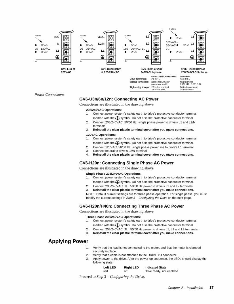
Step 2 – Connecting AC Power
Acceptable ranges of AC input voltage are listed below for each drive :
Drive AC Input RangeGV6-L3n 95 – 132VACGV6-U3n/U6n/U12n 95 – 264VACGV6-H20n 165 – 264VAC [single phase (1∅ ) or three phase power (3∅ )]GV6-H40n 165 – 264VAC [three phase power (3∅ ) only]
WARNING
You must connect the drive’s protective conductor terminal, marked with the symbol, to a reliable system safety earth. Make the connection directly, by means
of a low impedance path less than or equal to 0.1 ohm (no fuses, etc.). Undernormal operation, no current should flow through the safety earth connection.
WARNING
The drive’s barrier strip terminals are at hazardous voltages when power is appliedto the drive, and up to 30 seconds after power is removed. Lower voltages may still
be present for several minutes after power is removed. Reinstall the clear plasticterminal cover after you make connections.
Fuse InformationGemini drives have no internal fuses. For safety, you must provide a fuse in eachof the AC input lines. Recommended fuse types and sizes are:
Drive Type Fuse Style Rating Fuse TypeGV6-L3n (120VAC) 125VAC Time Delay 10 amp Type RK5 or betterGV6-U3n/6n/12n (120VAC) 125VAC Time Delay 30 amp Type RK5 or betterGV6-U3n/6n/12n (240VAC) 250VAC Time Delay 30 amp Type RK5 or betterGV6-H20n (208/240VAC, 1∅/ 3∅ ) 250VAC Time Delay 30 amp Type RK5 or betterGV6-H40n (208/240VAC, 3∅ ) 250VAC Time Delay 60 amp Type RK5 or better
The next table lists part numbers for suitable fuses, from several manufacturers:
Amps Bussmann Gould Littelfuse Grainger10 FRN-R-10 TR10R FLNR10 1A69330 FRN-R-30 TR30R FLNR30 1A69860 FRN-R-60 TR60R FLNR060 1A700
Connecting PowerGV6-L3n: Connecting AC Power
CAUTION
Do not operate the GV6-L3n above 132VAC, or the drive will bepermanently damaged.
120VAC Operations:1. Connect power system’s safety earth to drive’s protective conductor terminal,
marked with the symbol. Do not fuse the protective conductor terminal.2. Connect 120VAC, 50/60 Hz, single phase power line to drive’s L1 terminal.3. Connect neutral to drive’s N terminal.4. Reinstall the clear plastic terminal cover after you make connections.
Connections are illustrated in the next drawing.
Chapter 2 – Installation 17
GV6-L3n at120VAC
95 – 132VAC
GV6-U3n/6n/12nat 120/240VAC
VBUS–
L2/N
L195 – 264VAC
FusesN/C
N
L1
Fuses
GV6-H20n at 208/240VAC 1-phase
165 – 264VAC, 1∅
Fuses L3
L2
L1
GV6-H20n/H40N at 208/240VAC 3-phase
165VAC – 264VAC3∅
L3
L2
L1
Fuses
GV6-L3/U3/U6/U12/H20:Drive terminals: #8 (M4).Mating terminals: spade fork, 0.325" maximum width.Tightening torque: 20 in-lbs nominal, 24 in-lbs max.
GV6-H40:#10 (M5).ring terminal,0.25" I.D., 0.50" O.D.20 in-lbs nominal,24 in-lbs max.
Power ConnectionsGV6-U3n/6n/12n: Connecting AC PowerConnections are illustrated in the drawing above.
208/240VAC Operations:1. Connect power system’s safety earth to drive’s protective conductor terminal,
marked with the symbol. Do not fuse the protective conductor terminal.2. Connect 208/240VAC, 50/60 Hz, single phase power to drive’s L1 and L2/N
terminals.3. Reinstall the clear plastic terminal cover after you make connections.
120VAC Operations:1. Connect power system’s safety earth to drive’s protective conductor terminal,
marked with the symbol. Do not fuse the protective conductor terminal.2. Connect 120VAC, 50/60 Hz, single phase power line to drive’s L1 terminal.3. Connect neutral to drive’s L2/N terminal.4. Reinstall the clear plastic terminal cover after you make connections.
GV6-H20n: Connecting Single Phase AC PowerConnections are illustrated in the drawing above.
Single Phase 208/240VAC Operations:1. Connect power system’s safety earth to drive’s protective conductor terminal,
marked with the symbol. Do not fuse the protective conductor terminal.2. Connect 208/240VAC, 1∅ , 50/60 Hz power to drive’s L1 and L2 terminals.3. Reinstall the clear plastic terminal cover after you make connections.NOTE: Default current settings are for three phase operation. For single phase, you mustmodify the current settings in Step 3 – Configuring the Drive on the next page.
GV6-H20n/H40n: Connecting Three Phase AC PowerConnections are illustrated in the drawing above.
Three Phase 208/240VAC Operations:1. Connect power system’s safety earth to drive’s protective conductor terminal,
marked with the symbol. Do not fuse the protective conductor terminal.2. Connect 208/240VAC, 3∅ , 50/60 Hz power to drive’s L1, L2 and L3 terminals.3. Reinstall the clear plastic terminal cover after you make connections.
Applying Power1. Verify that the load is not connected to the motor, and that the motor is clamped
securely in place.2. Verify that a cable is not attached to the DRIVE I/O connector.3. Apply power to the drive. After the power-up sequence, the LEDs should display the
following state:
Left LED Right LED Indicated Statered off Drive ready, not enabled
Proceed to Step 3 – Configuring the Drive.

18 Gemini GV6 Hardware Installation Guide
Step 3 – Configuring the Drive
Gemini drives have no DIP switches or potentiometers for configuration. You willuse software tools to communicate with the drive and configure drive settings.
Configuration SoftwareTwo software programs are located on the Motion Planner CD-ROM. MotionPlanner runs on a personal computer (PC). Pocket Motion Planner runs on a palmPC or Handheld Personal Computer (HPC) that uses Windows CE 2.0 or higher,or on a PC. These programs are also available on the Compumotor web site athttp://www.compumotor.com.
Information about installing and using each of these software tools can be found inthe Gemini Programmer's Reference.
Establishing CommunicationsWe assume you are using a Gemini GV6 drive and that you have one serial port onyour PC.
WARNING
This procedure causes the motor shaft to move. Do not connect a load to the shaft.
1. Verify that a load is not connected to the motor, and that the motor is clampedsecurely in place.
2. Verify that a cable is not attached to the DRIVE I/O connector.
3. Using a null modem cable, connect the drive’s RS-232/485 connector to the serialport on your PC, palm PC, or HPC. (A null modem cable is available from Compu-motor. See Appendix A Specifications for more information.) It is not necessary toturn off AC power before you plug in an RS-232 cable; however, connect RS-485cables before applying AC power.
4. Install and launch Motion Planner or Pocket Motion Planner.
Proceed to Configuring the Drive.

Chapter 2 – Installation 19
Configuring the DriveChoose one of the columns below, based upon which software program you are using—Motion Planner, orPocket Motion Planner—and follow the procedure to configure your drive.
NOTE: If this is not the first time the drive has been configured, issue an RFS command (Return to FactorySettings) from the terminal emulator, before performing the following procedures.
Configuring the Gemini Drive withMotion Planner
1. Install and launch Motion Planner
2. When the product selection dialog appears, select aGemini GV6 drive and select the COM port to whichthe drive is connected.
3. To verify communications with the drive, click the“Terminal” tab on the bottom of the screen to enterterminal mode. Issue the following command:
TREV (transfe rs the drive’s revision level)
Revision level information for your drive should appearon the screen.
To solve communication problems: see RS-232/485 Communications in Chapter 4 – Special Features.
4. In the Editor window, click on the Gemini button at thetop of the window to launch the setup wizard.
5. Select “Express Setup”, and select “Initialize wizardwith factory defaults”. (If you wish to keep the existingdrive configuration, you should upload it and theninitialize from the editor.)
6. Click the “Next” button to proceed with the wizard. Fillin the dialogs as prompted, including choosing a motorseries, frame size, and part number. At the end of thewizard, click the “finish” button; this creates the setupcode and places it in the Editor window. (For GV6-H20using single phase power, see the Note below.)
7. Select File/Save to save the setup code to a file (*.prg)on your hard drive.
8. Select Communications/Download to download thesetup code (contents of the Editor window) to theGemini drive. When the download is complete, chooseto “Reset” the drive.
Drive setup is complete. All of the setup parameters(command values) are stored in the Gemini drive’sEEPROM and are automatically recalled when youcycle power or reset the drive.
9. Click the “Terminal” tab on the bottom of the screen toenter terminal mode.
10. Issue a DMODE13 command. This configures thedrive for autorun mode, in which the motor runs openloop in the clockwise direction at 1 rps. (The motor willnot begin turning, though, because you have not yetenabled the drive.)
Proceed to Step 4 – Verifying Correct SystemInstallation.
Configuring the Gemini Drive withPocket Motion Planner
1. Install and launch Pocket Motion Planner.
2. Select “Tools/Config Tool”.
3. Select “Edit Current Configuration” for factory defaults.(Or upload the existing configuration, and then select“Edit Current Configuration”.)
4. Select drive type by choosing “Auto Detect”. Thesoftware will identify the drive type, and automaticallyuse settings for your specific drive type. If themessage “Auto Detect Failed” appears, see RS-232Communication Problems in Chapter 4 Troubleshoot-ing.
5. Select “Express Setup”.
6. Choose a motor series, frame size, and part number.(For GV6-H20 using single phase power, see the Notebelow.)
7. Save your configuration file.
8. Download the configuration file to the Gemini drive;choose to “Reset” the drive.
9. Enter terminal mode.
10. Issue a DMODE13 command. This configures thedrive for autorun mode, in which the motor runs openloop in the clockwise direction at 1 rps. (The motor willnot begin turning, though, because you have not yetenabled the drive.)
Proceed to Step 4 – Verifying Correct SystemInstallation.
NOTE: GV6-H20 – default current values are for three phase operation. If you use single phase power with the GV6-H20, youmust manually modify the current values as follows:
• Set continuous current (DMTIC) to 11.3 amps rms or less• Set peak current (DMTIP) to 28.3 amps rms or less
Depending upon which motor you selected, your settings may already be lower than these limits.

20 Gemini GV6 Hardware Installation Guide
Step 4 – Verifying Correct System Installation
Commanding Motion in Autorun ModeIn this procedure you will enable the drive; the motor will then rotate in autorunmode. This will verify correct system wiring and drive configuration.
1. Connect a jumper wire between Pin 1 and Pin 2 on the 50 pin DRIVE I/O connector.(For connector diagrams, cable color codes, and breakout module information seeAppendix A Specifications.)
2. Issue the following command to the drive:
DRIVE1 (enables the drive)
3. Verify that the drive is enabled. (Left LED is illuminated green; right LED flashesyellow/green during autorun.)
4 Verify that the motor is rotating clockwise at approximately one revolution persecond, as viewed from the shaft end of the motor. (The motor is turning becauseearlier you configured the drive for autorun.)
Proceed to Commanding Motion Under Program Control.
Commanding Motion Under Program ControlIn this procedure you will use the Gemini command language to make the motorturn. This will verify that your system is installed correctly.
1. Issue the following commands to change the drive mode and verify correctresolution:
DRIVEØ (disables the drive and stops motion)
DMODE12 (changes mode from autorun to controller/drive mode)
DRIVE1 (enables the drive)
ERES (reports resolution; verify correct resolution for your motor)
2. Issue the following commands to the drive to make the motor turn:
LHØ (disables limits)
MAØ (enables incremental positioning mode; disables absolute mode)
MCØ (enables incremental positioning mode; disables continuous mode)
A10 (sets acceleration to 10)
V1 (sets velocity to 1)
D4000 (sets distance to 1 rev (if ERES = 4000) )
GO (initiates motion)
3. Verify that the motor rotates one revolution and then stops.
This completes the Express Setup procedure.

Chapter 2 – Installation 21
What’s Next?
This chapter has given you information and instructions for performing an ExpressSetup. The following list explains the steps you should take to complete yourinstallation, and indicates where to find additional information for each of thosesteps.
1. Mount the drive. For information on drive dimensions, environmental specifica-tions, airflow and cooling, etc., see Appendix A Specifications.
2. Mount the motor. For information on motor dimensions, motor cables, encoders,speed/torque curves, etc., see the separate Gemini Motor Reference Manual.
3. Make System Connections. Information about Compumotor cables is inAppendix A Specifications. For information on cabling practices to reduce electricalnoise, see Appendix C Regulatory Compliance: UL and CE.
Connect any of the drive’s optional features you may wish to use (see Appendix ASpecifications for more information):
• Reset Input
• VINref – Voltage Input Reference
• Digital Inputs (and CNTRL-P)
• Digital Outputs
• Encoder Output
• Analog Monitor
• Analog Input
Connect any of the drive’s special features you may wish to use (see Chapter 4Special Features for more information):
• Relay, and how to control a Motor Brake
• +24VDC “Keep Alive” Power
• Multiple Drive Installations
• Connecting drive power buses together
• Regeneration and the GPDM Power Dissipation Module
• Aligning the Resolver
• RS-232 Daisy Chain
• RS-485 Multi-Drop
4. Connect the Load.
5. Configure Your Drive. After completing your hardware installation in Steps 1 – 4above, proceed to Chapter 3 Configuration for information about additional driveconfiguration options.
6. Tune Your System. Tune your system according to the instructions found at theend of Chapter 3 Configuration.

22 Gemini GV6 Hardware Installation Guide

Chapter 3 – Configuration 23
3Configuration
IN THIS CHAPTER
• Configuration
• Tuning Procedures
C H A P T E R T H R E E

24 Gemini GV6 Hardware Installation Guide
Configuration
You can configure the Gemini drive’s settings for optimum system performance.For most of these settings, configuration is optional—if you do nothing, the drivewill use default values the very first time it powers up. If you change any settings,the new settings are saved automatically. Most changed settings are effectiveimmediately, but some require that you issue a reset (software RESET command,reset input, or cycle power) before the drive acts upon them.
This chapter will give an overview of all software commands that configure drivesettings. For more in depth descriptions about the software commands, see theseparate Gemini Programmer's Reference.
At the end of this chapter, we have provided tuning procedures you can use toconfigure the Gemini drive’s tuning settings.
Software Programs for ConfigurationTwo software programs are located on the Motion Planner CD-ROM. MotionPlanner runs on a personal computer (PC). Pocket Motion Planner runs on a palmPC or Handheld Personal Computer (HPC) that uses Windows CE 2.0 or higher,or on a PC. These programs are also available on the Compumotor web site athttp://www.compumotor.com.
Information about installing and using each of these software tools can be found inthe Gemini Programmer's Reference.
Overview of Configuration Commands
Motion Planner and Pocket Motion Planner’s configuration procedures presentcommands in groups organized by function. The overview below is organizedsimilarly to the software’s Full Configuration procedure. (Express Setup, whichwas discussed in Chapter 2 Installation, gives you fewer configuration options.)
Motor SettingsIf you select a Compumotor motor from the list of motors the software presents toyou, the software will send settings to the drive for the motor you selected. Nofurther motor setting configuration is necessary on your part.
If you use a non-Compumotor motor, or choose to manually configure aCompumotor motor, use the following commands to configure motor settings.Also see Appendix B – Using Non-Compumotor Motors for additional instructions.
Command Description
ERES feedback resolution (encoder or resolver)
DMTIC continuous current
DMTICD continuous current derating
DMTKE motor constant
DMTRES line-to-line resistance
DMTJ rotor inertia
DPOLE number of pole pairs
DMTW rated speed

Chapter 3 – Configuration 25
DMTIP peak current
DMTLMN minimum line-to-line inductance
DMTLMX maximum line-to-line inductance
DMTD motor damping
DMTRWC motor thermal resistance (winding to case)
DMTTCM motor case (and heatsink) thermal time constant
DMTTCW motor winding thermal time constant
DPWM PWM switching frequency
DMTMAX motor maximum temperature
SHALL Hall sensor orientation
System SettingsThe system settings configure the drive’s mode of operation, resolution, direction,and fault modes.
Drive SettingsCommand Description Options:
DMODE mode of operation: no mode defined
alignment mode
sequence (program)
autorun1
torque/force tuning mode
velocity tuning mode
position tuning mode
DMEPIT electrical pitch of magnets you enter a number
ORES pseudo encoder you enter a numberoutput resolution
DMTLIM torque limit you enter a number
DMTSCL torque scale you enter a number
DMVLIM velocity limit you enter a number1Autorun mode commands motion with no program control. It is used during ExpressSetup, and for troubleshooting.
Load SettingsCommand Description Options:
LJRAT load to rotor inertia ratio you enter a number
LDAMP load damping you enter a number
Fault SettingsCommand Description Options:
FLTDSB fault on disable can be turned on or off
SMPER maximum position error you enter a number
SMVER maximum velocity error you enter a number
DIFOLD enable current foldback can be turned on or off
DMTAMB motor ambient temperature you enter a number
DHALL fault on encoder/ can be turned on or offHall mismatch

26 Gemini GV6 Hardware Installation Guide
Input/Output (I/O) SettingsI/O settings configure the drive’s digital inputs and outputs, and analog monitors.
Digital InputsCommand Description Options:
LH hard limit enable both hard limits disabled
negative limit only
positive limit only
both hard limits enabled
INDEB input debounce time can be set in milliseconds
LHAD hard limit deceleration you enter a number
LHADA hard limit average decel. you enter a number
Input Definition and Sense configure up to 8 inputs
Digital OutputsCommand Description Options:
Output Definition and Sense configure up to 7 outputs
Analog MonitorsCommand Description Options:
DMONAV analog monitor A variable unused/turn off output
motor temperature
drive temperature
position error
velocity setpoint
actual velocity
acceleration setpoint
torque/force setpoint
actual (electrical) torque
velocity error
phase A actual current
phase B actual current
d-axis commanded current
d-axis actual current
q-axis commanded current
q-axis actual current
position setpoint
actual position
DMONAS analog monitor A scaling1 you enter a percentage1
DMONBV analog monitor B variable same choices as DMONAV
DMONBS analog monitor B scaling1 you enter a percentage1
1Monitor output is scalable from -2000% to +2000%, but is limited to ±10V peak to peak.

Chapter 3 – Configuration 27
Communications SettingsThe communication settings configure the drive for RS-232/485 communications.
RS-232/485Command Description Options:
ERRLVL error level you enter a number
ECHO echo enable can be turned on or off
Tuning SettingsTuning settings are divided into two groups: primary and advanced. Tuning can bedone in torque, velocity, or position mode. Tuning procedures for each of thesemodes are presented below. Relevant commands are:
Primary TuningCommand Description Options:
DIBW current loop bandwidth you enter a number
DVBW velocity loop bandwidth you enter a number
DPBW position loop bandwidth you enter a number
Advanced TuningCommand Description Options:
DIBW current loop bandwidth you enter a number
DVBW velocity loop bandwidth you enter a number
DPBW position loop bandwidth you enter a number
SGIRAT current (torque) damping ratio you enter a number
SGVRAT velocity damping ratio you enter a number
SGPRAT position damping ratio you enter a number
SGPSIG position/velocity bandwidth you enter a numberratio
SGINTE integration ON/OFF can be turned on or off
DNOTAF notch filter A frequency you enter a number
DNOTAD notch filter A depth you enter a number
DNOTAQ notch filter A quality factor you enter a number
DNOTBF notch filter B frequency you enter a number
DNOTBD notch filter B depth you enter a number
DNOTBQ notch filter B quality factor you enter a number
DNOTLD notch lead filter frequency you enter a number
DNOTLG notch lag filter frequency you enter a number

28 Gemini GV6 Hardware Installation Guide
Tuning Procedures
During the Express Setup procedure in Chapter 2 Installation, the drive usesdefault values for tuning parameters, based upon the motor information youentered. That procedure assumes that the motor is unloaded. In the followingtuning procedures, you will enter in system information that will characterize theload on the motor.
Entering Load SettingsThe main load setting you will adjust is LJRAT, which is the load-to-rotor inertiavalue for your system. The more accurately you know this value, the closer yourtuning bandwidth settings will correspond to the actual dynamic performance ofyour system. If you only know this value approximately, you can adjust this valueuntil you achieve the system performance you desire. The total system inertia isgiven by the following formula:
Total system inertia = motor rotor inertia*(1 + LJRAT)
If your system has significant mechanical damping, you will also want to adjustthe LDAMP setting which specifies system damping provided by the load. If youknow that you have significant damping in your system from your load but do notknow its exact value, you can adjust this value until you achieve the systemperformance that you desire.
Both the LJRAT and the LDAMP values can be set in the Full Configurationsection of Pocket Motion Planner or in the Full Setup section of the Gemini wizardin Motion Planner. These values can also be set in the terminal modes of PocketMotion Planner and Motion Planner. During the tuning process you may want touse the terminal emulator to establish appropriate values for these parameters andthen upload and save the drive’s full configuration settings for use with other units.
Position Mode TuningFor most applications, the default tuning parameters for position mode are set toprovide good, stiff motor shaft performance for a given load setting. With thedefault tuning parameters set in the Express Setup procedure, you need only set thesystem load-to-rotor inertia ratio and your system will be tuned. If your system hassignificant mechanical damping, you may need to set the system damping as well.Should you wish to modify the default values and fine tune your system forposition mode, use the following procedures.
WARNING
This procedure causes the motor shaft to move. Make sure that shaft motion willnot damage equipment or injure personnel.
Position Mode Tuning Procedure
Primary Tuning Procedure
1. Disable the drive.
2. Configure the drive for position tuning mode (DMODE17). In this mode, the drivecommands an alternating 1/4 revolution step change in position at a one secondrepetition rate.

Chapter 3 – Configuration 29
3. Enable the drive and observe your system’s response. (If necessary, you canconnect an oscilloscope as described in Advanced Tuning below.)
Ringing or an oscillating response indicates that the position loop bandwidth is toohigh. To eliminate oscillations:
• decrease bandwidth using the DPBW command.
A sluggish response indicates that position loop bandwidth is too low. To improvethe response:
• increase bandwidth by using the DPBW command.
NOTE: Ringing, oscillations, or a sluggish response can also indicate inaccuratedrive settings for LJRAT or LDAMP.
4. After you achieve a satisfactory system response, reconfigure the drive for positionmode (DMODE12). This completes the primary tuning procedure.
If you are unable to achieve a satisfactory response, proceed to the advancedtuning procedure below.
Advanced Tuning Procedure
1. Disable the drive.
2. Configure the drive for position tuning mode (DMODE17). In this mode, the drivecommands an alternating 1/4 revolution step change in position at a one secondrepetition rate.
(In some applications a different move profile may give better results. Choose amove similar to that required by your application, but using fast acceleration anddeceleration rates. Be sure the maximum velocity of your move is well below therated speed of your drive/motor combination.
3. Configure ANALOG MONITOR A to show position error (DMONAV3).
4. Connect one channel of your oscilloscope to the drive’s ANALOG MONITOR A (pin21). Connect your oscilloscope’s ground to the drive’s ANALOG GROUND (pin 25).
5. Adjust your oscilloscope to display position error. (The analog monitor can bescaled, in percent, with the DMONAS command.)
6. Enable the drive and observe your system’s response. Position error will increaseduring acceleration, but should decay smoothly to near zero without significantringing or instability.
Ringing or an oscillating response indicates that the position loop bandwidth is toohigh, or the position loop damping is too low. To eliminate ringing or oscillations:
• decrease bandwidth using the DPBW command; then, if necessary:
• adjust damping by using the SGPRAT command. Use the value thatgives the best performance.
• in applications with backlash or high static friction, disabling the velocityintegrator (SGINTE0) can help improve stability.
• NOTE: In position mode, the velocity loop bandwidth tracks changes inposition loop bandwidth by a ratio set by the SGPSIG command. Inposition mode, the DVBW command is ignored.
A sluggish response indicates that position loop bandwidth is too low, or positionloop damping is too high. To improve the response:
• increase bandwidth by using the DPBW command; then, if necessary:
• adjust damping by using the SGPRAT command. Use the value thatgives the best performance.
NOTE: Ringing or a sluggish response can also indicate inaccurate drive settingsfor LJRAT or LDAMP.
7. After you achieve a satisfactory system response, reconfigure the drive for positionmode (DMODE12). This completes the advanced tuning procedure.
If ringing or oscillations persist, and do not seem to be affected by the aboveadjustments, you may need to use notch filters or lead/lag filters. See the FilterAdjustments procedure below.

30 Gemini GV6 Hardware Installation Guide
Filter AdjustmentsIf the previous tuning procedures did not eliminate ringing or oscillations, thenmechanical resonances may be causing problems with your system’s response.
Before trying the procedure below, we recommend that you check your mechani-cal system, especially the mechanical stiffness and mounting rigidity of yoursystem. Use bellows or disk style couplers, not helical couplers. Once you haveoptimized your mechanical system, filters may allow increased performance,without causing system instability.
Filters can improve response by reducing system gain over the same frequenciesthat contain resonances. You can then increase the gain for frequencies outside thisrange, without exciting the resonance and causing instability.
The first procedure below describes how to set the drive’s two notch filters, toreduce resonance and improve your system’s response. The second and thirdprocedures describe how to set the drive’s lead and lag filters.
WARNING
These procedures cause the motor shaft to move. Make sure that shaft motion willnot damage equipment or injure personnel.
Notch Filter Adjustment Procedure
1. Configure the analog monitor to show q-axis current (DMONAV19).
2. Configure the drive for position tuning mode (DMODE17).
3. Configure DMTLIM to approximately 1/3 of the default value for your Compumotormotor.
4. Connect one channel of your oscilloscope to the drive’s ANALOG MONITOR A (pin21). Connect your oscilloscope’s ground to the drive’s ANALOG GROUND (pin 25).
5. From the oscilloscope display, observe the system’s response to the tuning mode’sstep input. Note the frequency of the oscillatory current waveform that is superim-posed on the 1 Hz step command signal.
6. Using the DNOTAF command, set the notch filter to the frequency noted in Step 5.
7. Using the DNOTAD command, slowly increase the depth of the notch filter from 0.0to 1.0 until the ringing decreases.
8. Continue to observe the response to step command signal. Ringing should bereduced or eliminated.
9. Adjust the Q of the filter (DNOTAQ command). Use the following guidelines:
• Set Q as low as possible. Resonances change with load; therefore, yoursystem will be more robust with a lower Q value. (Default = 1)
• If Q is too low, system stiffness will be reduced outside the resonant range.
• If Q is too high, the response peak may shift in frequency.
10. After reducing the resonance, you may notice a second resonance. Use the secondnotch filter (DNOTBF, DNOTBD and DNOTBQ) to reduce the second resonance.Follow the same procedure as outlined in steps 1 – 9 above.
11. If you are done adjusting filters, reconfigure DMTLIM to its default value. Otherwise,proceed to the Lag Filter Adjustment procedure below.

Chapter 3 – Configuration 31
Lag Filter Adjustment Procedure
The lag filter can act as a low pass filter, and reduce the effects of electrical noise on thecommanded torque. (It can also reduce the effects of resonance at low frequencies—below 60 Hz—where the notch filters are not effective.)
1. As described in Steps 2 – 3 in the Notch Filter Adjustment procedure above, reduceDMTLIM and connect an oscilloscope.
2. Verify that the lead filter is turned off (DNOTLDØ).
3. Configure the drive for position tuning mode. Observe the system’s response to thetuning mode’s step input.
4. Choose a value for the lag filter (DNOTLG) that reduces low frequency resonanceand provides satisfactory system performance.
5. If you are done adjusting filters, reconfigure DMTLIM to its default value. Otherwise,proceed to the Lead/Lag Filter Adjustment procedure below.
Lead/Lag Filter Adjustment Procedure
The lead filter can counteract the effects of the lag filter at higher frequencies. Do not usethe lead filter by itself—if you use the lead filter, you must also use the lag filter.
1. As described in Steps 2 – 3 in the Notch Filter Adjustment procedure above, reduceDMTLIM and connect an oscilloscope.
2. Set the lag filter (DNOTLG) as described above.
3. Configure the drive for position tuning mode. Observe the system’s response to thetuning mode’s step input.
4. Choose a value for the lead filter (DNOTLD) that improves system performance.This value will typically be higher in frequency than the lag filter setting.
5. You must choose a value for the lead filter that is higher in frequency than the lagfilter value. However, do not set the lead filter higher than four times the lag filterfrequency, or a drive configuration warning will result, and the drive will use theprevious filter settings.
6. If you are done adjusting filters, reconfigure DMTLIM to its default value.

32 Gemini GV6 Hardware Installation Guide

Chapter 4 – Special Features 33
4Special Features
IN THIS CHAPTER
• Relay
• +24VDC Keep Alive Power Connections
• Multiple Drive Installations
• V BUS±
• Regeneration Protection and the GPDM
• Aligning the Resolver
• RS-232/485 Communications
• Updating the Drive’s Operating System
C H A P T E R F O U R

34 Gemini GV6 Hardware Installation Guide
Relay Connections (optional)
To use the drive’s internal relay, connect your external circuit to theRELAY COM and RELAY N.O. terminals. The next drawing shows a typicalapplication—connecting a motor brake to the relay terminals.
GEMINI Drive
RELAY COM
RELAY N.O.
Motor Cable
Flying Leads from Cable Connector
+5VDC
User Supplied+24VDC
User Supplied24V Return
RecommendedDiode(1N4936)
Relay Connections
The relay is normally open. When the drive is enabled, it holds the relay closed. Ifthe drive faults or is disabled, the relay will open.
Relay Operation:Drive Condition: Relay State:
Enabled Closed
Faulted Open
No AC power*, or not enabled Open
* +24VDC power does not affect the relay. With +24VDC applied, the relay will be open ifAC power is not applied.
Relay Specifications:Relay Type: Dry contact mechanical relay
Normally open
Relay Rating: 5 amps at 24VDC or 120VAC
See the OUTFNC and OUTLVL commands in the Gemini Programmer’s Refer-ence for more information on configuring the relay.
+24VDC “Keep Alive” Power Connections (optional)
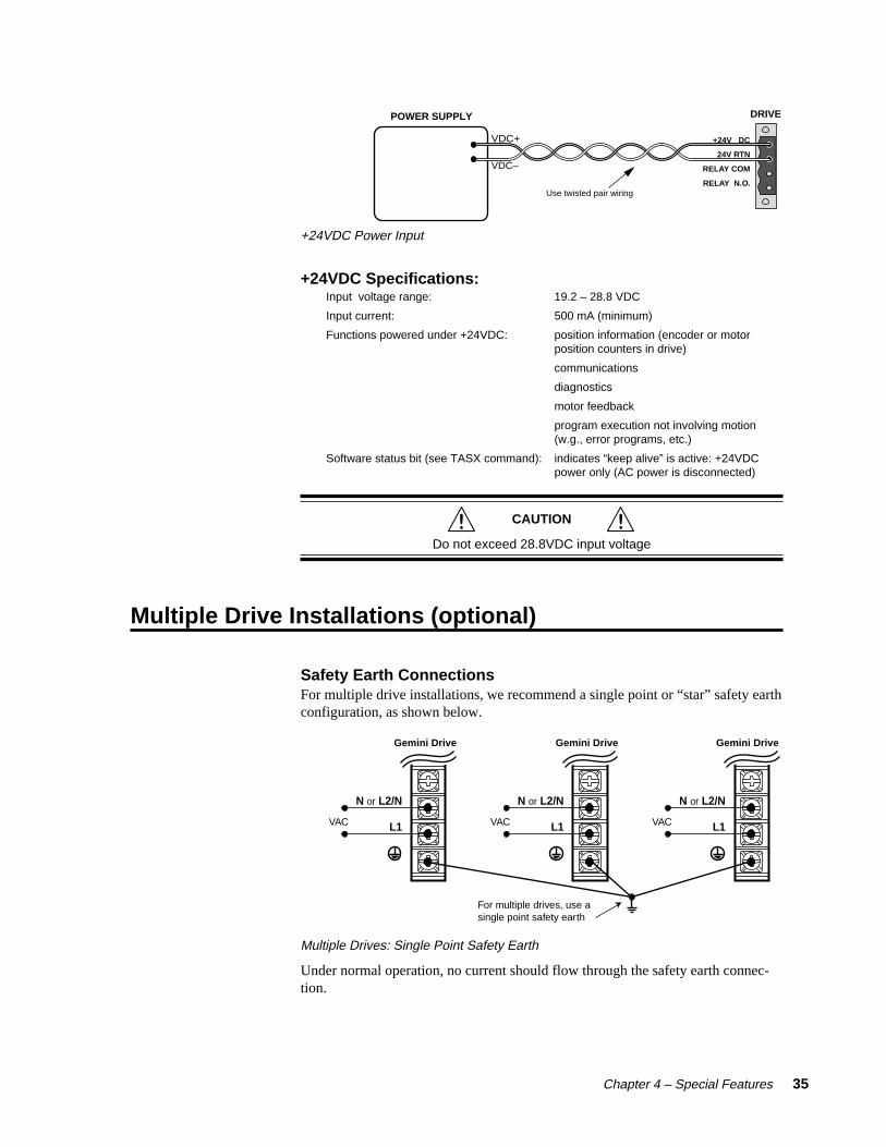
The following drawing shows how to connect an external +24VDC power sourceto the drive. Use the removable terminal connector that is supplied with the drive.
With +24VDC applied, the drive’s internal control board will remain poweredwhen the primary AC power source is disconnected, and will maintain severalimportant functions, including communication diagnostics, position feedback, andother logic functions.
Chapter 4 – Special Features 35
DRIVEPOWER SUPPLY
VDC+
VDC–
+24V DC
24V RTN
RELAY COM
RELAY N.O.Use twisted pair wiring
+24VDC Power Input
+24VDC Specifications:Input voltage range: 19.2 – 28.8 VDC
Input current: 500 mA (minimum)
Functions powered under +24VDC: position information (encoder or motorposition counters in drive)
communications
diagnostics
motor feedback
program execution not involving motion(w.g., error programs, etc.)
Software status bit (see TASX command): indicates “keep alive” is active: +24VDCpower only (AC power is disconnected)
CAUTION
Do not exceed 28.8VDC input voltage
Multiple Drive Installations (optional)
Safety Earth ConnectionsFor multiple drive installations, we recommend a single point or “star” safety earthconfiguration, as shown below.
Gemini Drive Gemini Drive Gemini Drive
VAC
N or L2/N
L1 VAC
N or L2/N
L1 VAC
N or L2/N
L1
For multiple drives, use asingle point safety earth
Multiple Drives: Single Point Safety Earth
Under normal operation, no current should flow through the safety earth connec-tion.

36 Gemini GV6 Hardware Installation Guide
Connecting V Bus±: Sharing the Power Bus (optional)You can connect the power buses of Gemini GV6-U3n/U6n/U12n/H40n drives inparallel, through the V BUS+ and V BUS- terminals. With the buses connected inparallel, regenerated energy from one drive will be used by the other drives. (Donot connect GV6-H20n drives in parallel to each other or to other Gemini drives.)
WARNING
V BUS+ and V BUS- terminals are at hazardous voltages when power is applied tothe drive, and for up to 30 seconds after power is removed. Lower voltages may
still be present for several minutes after power is removed. Reinstall the clearplastic terminal cover after you make connections.
CAUTION
Connect together only V BUS± terminals of drives that share the same fused ACpower source, as shown below.
VBUS+
VBUS–
L2/N
L1
VBUS+
VBUS–
L2/N
L1
VBUS+
VBUS–
L2/N
L1
VAC
GV6-U3/U6/U12/H40* GV6-U3/U6/U12/H40* GV6-U3/U6/U12/H40*
Use a single pointsafety earth
Connect to GPDM,if necessary
Not shown: 3-phase AC connections for GV6-H40
*
Fuses
Sharing the Power Bus
If excess regenerated energy causes an overvoltage or regeneration fault, you canconnect the Gemini Power Dissipation Module (GPDM) to the drive’s V BUS±terminals. See Regeneration Protection below for connection instructions andmore information about the GPDM.
NOTE: Because the Gemini drive has a current inrush limiter, we recommend thatyou do not add additional bus capacitance to V BUS+ and V BUS-.
Regeneration Protection
The following sections describe regeneration protection for Gemini drives, and theGemini Power Dissipation Module.

Chapter 4 – Special Features 37
Regeneration with GV6-L3n/H20n/H40nGemini GV6-L3n/H20n/H40n drives have internal circuitry to protect them fromregeneration—energy from the load during deceleration. Excessive regenerationcan cause either of two faults:
• Overvoltage Fault (see Overvoltage Protection in Appendix A Specifications)• Regeneration Fault (if regeneration occurs for an extended period of time)
Specifications for regeneration protection are:Maximum Activation Conditions
Drive Dissipation (watts): Pulse Energy Turn on: Turn off:
GV6-L3n 8W continuous 1.3 KJ 200VDC 193VDC500W peak
GV6-H20n 25W continuous 6 KJ 396VDC 385VDC(100W continuous at 40°C)6KW peak
GV6-H40n 150W continuous 9 KJ 396VDC 385VD9KW peak
Results of Fault: Latched fault; power to motor is turned OFF; fault output is activatedLEDs: Left = illuminated RED; Right = off
All temperatures in moving 50°C ambient air, unless otherwise noted.
Regeneration with GV6-U3n/U6n/U12nGemini GV6-U3n/U6n/U12n drives do not have internal regeneration circuitry.Consequently, they cannot cause a regeneration fault. The drives can absorb thefollowing amounts of regenerated energy in their internal capacitors:
AbsorbDrive (joules):GV6-U3n 44 J (from 340 – 410VDC: 1680 µF)GV6-U6n/12n 59 J (from 340 – 410VDC: 2240 µF)
If excess regenerated energy causes overvoltage faults, you can connect theGemini Power Dissipation Module (GPDM) to the V BUS± terminals of thesedrives. Regenerated energy from the drive will then be dissipated in the GPDM.
Gemini Power Dissipation Module (GPDM)The GPDM is designed for use with GV6-U3n/U6n/U12n drives. (NOTE: If youuse a GV6-H20n/H40n drive, and regeneration in your application exceeds thedissipation capacity of the internal regeneration circuit (see above), you mayconnect a GPDM to dissipate the excess regenerated energy.)
The GPDM dissipates excess regenerated energy in its internal resistors. Ifregenerated energy from the motor causes the drive’s DC bus voltage to increaseto 398VDC, the GPDM connects its resistors in shunt across the DC bus. Energyin the drive’s capacitors is then dissipated as heat in the GPDM’s resistors.
When the DC bus voltage decreases to 380VDC, the GPDM disconnects itsresistors. If the motor continues to regenerate energy and the bus again rises to398VDC, the process repeats until regeneration stops or a fault occurs.
The GPDM monitors three parameters, and generates a fault if any of the follow-ing are exceeded:
• maximum duty cycle• maximum temperature• maximum energy pulse
If the GPDM faults, it will disconnect itself from the DC bus and illuminate its redLED. Its internal fan will continue blowing. The GPDM will automatically clear

38 Gemini GV6 Hardware Installation Guide
the fault and reset itself within 10 seconds (an overtemperature fault may takelonger to clear). When it resets itself, the GPDM will illuminate its green LED; theGPDM is then again ready to dissipate regenerated energy.
If regeneration continues while the GPDM is in a faulted state, the drive mayexperience an overvoltage fault. If you look for the cause of the drive overvoltagefault, be aware that it may have been caused by a prior GPDM fault—even thoughthe left LED is now green.
If excessive regeneration continues to cause GPDM faults or drive faults, you canconnect a second GPDM, as shown in the GPDM Connections drawing below.
GPDM Specifications
Activation Conditions: Turn on: 398VDCTurn off: 380VDC
Resistance: Six 100 ohm resistors in parallel (16.7 ohm equivalent)
Continuous Dissipation: 300W in 25°C internal ambient
Maximum Dissipation: 9KW
Maximum Pulse Energy: 13KJ (pulse rating of resistors, repeatable, not toexceed continuous rating)
Weight: 3.1 pounds (1.4 kg)
GPDM LED Color Code:
Left: Right: Status:Green Off readyGreen Yellow* activeRed Off fault (max. temperature, duty cycle, or pulse exceeded)
*Yellow LED may flash or be continuously illuminated until GPDM stops dissipating
GPDM Connection Instructions
WARNING
Sheet metal and exhaust air at the top of the enclosure are hot. Avoid contact.
WARNING
V BUS+ and V BUS- terminals are at hazardous voltages when power is applied tothe drive, and for up to 30 seconds after power is removed. Lower voltages may
still be present for several minutes after power is removed. Reinstall the clearplastic terminal cover after you make connections.
WARNING
Only connect V BUS± terminals of drives that share the same fused AC powersource, as shown in the next drawing.
Connecting the GPDM
1. Connect up to three Gemini Servo Drives to one GPDM. (Connect only GV6-U3n/U6n/U12n drives; do not connect any other Gemini drives to the GPDM.)
2. Connect drive V BUS+ terminals to V BUS+ on the GPDM
3. Connect drive V BUS– terminals to V BUS– on the GPDM
4. For multiple drives, connect drive safety earth terminals to a single point ground.
5. Keep connections between drive and GPDM less than 12 inches (300 mm). Use 14AWG (2.5 mm2) or greater diameter wire.

Chapter 4 – Special Features 39
The next figure shows a typical installation.
VBUS+
VBUS–
L2/N
L1
VBUS+
VBUS–
L2/N
L1
VBUS+
VBUS–
L2/N
L1
VAC
GV6-U3n/6n/12n GV6-U3n/6n/12nGV6-U3n/6n/12n
Use a single pointsafety earth
30Afuses
VBUS+
VBUS–
Connect 2nd GPDM, if necessary
VBUS+
VBUS–
GPDM Connections
The next figure shows GPDM dimensions.
6.0(152)
5.4(138)
2.75(70)
1.38(35)
7.0(177.8)
7.75(197)
8.0(203)
3x clearancefor #8 or M4mounting screws
1.00(25.4 )
0.88(22.2)
Dimensions – GPDM Power Dissipation Module
40 Gemini GV6 Hardware Installation Guide
Aligning the Resolver (optional)
Resolvers on Compumotor motors are aligned at the factory. Ordinarily, no furtheralignment is required. However, you may wish to align the resolver if you suspectthe resolver is misaligned, or if you are using a non-Compumotor motor.
A Note About Resolver SpeedResolver speed describes the relationship between resolver electrical revolutionsand shaft mechanical revolutions. For example, if one resolver electrical revolu-tion is equal to one shaft mechanical revolution, the resolver is a “single speed” or“one speed” resolver. If two electrical revolutions equal one mechanical revolu-tion, the resolver is a “two speed” resolver.
The following alignment procedures assume you have configured the drive with anaccurate resolver speed value. For Compumotor motors, resolver speed is loadedfrom the motor configuration file.
Resolver Alignment Procedures
There are three methods to align the resolver:
• Method 1 – Enter a known resolver offset angle.
• Method 2 – Find an unknown resolver offset angle, and store it in the drive’snonvolatile memory.
• Method 3 – Loosen the resolver cleats and rotate the housing while monitoringoffset angle. Secure the housing when the angle is zero degrees.
Details for these methods are given below.
Method 1 – Entering a Known Offset Angle
1. Disconnect the load from the motor shaft. The shaft should be free to rotate.
2. Issue an SRSET command; include the desired offset angle. For example, enteringSRSET10 automatically sets the offset angle to 10 resolver electrical degrees.
WARNING
The SRSET command takes effect immediately. If you set the offset angleincorrectly the system may become unstable.
3. Disable the drive. Upon being disabled, the drive stores the value for the offsetangle into nonvolatile memory. It uses this value for all future operations. You donot need to perform this procedure again.

Chapter 4 – Special Features 41
Method 2 – Finding an Unknown Offset Angle
Use this method if you do not know your resolver’s offset angle.
1. Disconnect the load from the motor shaft. The shaft should be free to rotate.
2. Verify correct motor wiring. See the Gemini Motor Reference Manual for wiringinformation for Compumotor motors.
3. Configure the drive for your motor, as described in Chapter 2 Installation. If you usea non-Compumotor motor, create and download a motor configuration file for yourmotor.
4. Enable the drive.
5. Issue a DMODE13 command to put the drive into autorun mode. The motor shouldbegin turning clockwise at approximately 1 rps, as viewed from the shaft end of themotor. If the motor turns in the wrong direction or at the wrong speed, check themotor wiring, and verify correct motor pole configuration (DPOLE command).
6. Issue a DMODE11 command to put the drive into alignment mode. The motor willstop turning.
7. Issue an SRSET command. The motor may turn as much as 1/2 revolution. It willstop when the motor magnetic poles align.
8. Disable the drive. Upon being disabled, the drive stores the value for the offsetangle into nonvolatile memory. It uses this value for all future operations. You donot need to perform this procedure again.
9. Return the drive to the appropriate mode of operation (DMODE command).
Method 3 – Rotating the Resolver Housing
Use this method to manually rotate the resolver to a specific offset angle (usually zerodegrees).
1. Disconnect the load from the motor shaft. The shaft should be free to rotate.
2. Verify correct motor wiring. See the Gemini Motor Reference Manual for wiringinformation for Compumotor motors.
3. Configure the drive for your motor, as described in Chapter 2 Installation. If you usea non-Compumotor motor, create and download a motor configuration file for yourmotor.
4. Enable the drive.
5. Issue a DMODE13 command to put the drive into autorun mode. The motor shouldbegin turning clockwise at approximately 1 rps, as viewed from the shaft end of themotor. If the motor turns in the wrong direction or at the wrong speed, check themotor wiring, and verify correct motor pole configuration (DPOLE command).
6. Issue a DMODE11 command to put the drive into alignment mode. The motor willstop turning.
7. Issue an SRSET command. The motor may turn as much as 1/2 revolution. It willstop when the motor magnetic poles align.
8. Loosen the cleats that hold the resolver housing onto the motor.
9. Issue a TSROFF command repeatedly as you slowly turn the resolver housing. TheTSROFF command indicates the present resolver offset angle.
10. Turn the resolver housing until the offset angle is zero degrees (or until you obtainyour desired offset angle).
11. Tighten the cleats.
12. Disable the drive. Upon being disabled, the drive stores the value for the offsetangle into nonvolatile memory. It uses this value for all future operations. You donot need to perform this procedure again.
13. Return the drive to the appropriate mode of operation (DMODE command).

42 Gemini GV6 Hardware Installation Guide
RS-232/485 Communications
The Gemini drive has a single serial port marked, “RS-232/485,” on the front of theunit. In the following this port will be referred to as the COM port. The Geminidrive uses a binary language for communication; it does not use ASCII. To enable6000 ASCII level communication in a terminal mode, the Gemini uses a translatorutility in Pocket Motion Planner and in the CommServer (for use with MotionPlanner). In all other ways, the serial communication functions in the Geminibehave like other Compumotor products. Gemini drives can be connected togetherin RS-232 Daisy Chains and RS-485 Multi-Drop configurations.
In this section:• Establishing Communications
• Configuring the serial port
• RS-232 Communications
• RS-232 Daisy Chaining
• RS-485 Communications
• RS-485 Multi-Drop
Establishing CommunicationsThe drive’s configuration port is a 9 pin D-connector. You can use it for either RS-232 or four wire RS-485 communications, as shown in the next drawing.
21 3 4 5
6 7 8 9
Rx-(RD A)
Tx-(TD A)
6 7 8 9
21 3 4 5
Rx Tx GndGndRx+
(RD B)Tx+
(TD B)
Gemini DriveRS-232 Connections
1. RS-485 Rx+ (RD B)2. RS-232 Receive3. RS-232 Transmit4. RS-485 Tx+ (TD B)5. Ground6. No connection7. RS-485 Rx– (RD A)8. RS-485 Tx– (TD A)9. No connection
Gemini DrivePin Assignments
Gemini DriveRS-485 Connections
RS-232/485 Connections
To communicate with the drive, connect the drive’s RS-232/485 connector to a PCrunning Motion Planner, or to a palm PC running Pocket Motion Planner withWindows CE. Verify your computer’s connector pinout; you may need to use a“null modem” cable to connect your computer’s transmit terminal to the Gemini’sreceive terminal, your computer’s receive terminal to the Gemini’s transmitterminal, and your computer’s ground terminal to the Gemini’s ground terminal.
Configuring the Serial PortThe following commands can be used to configure the Gemini serial port and theterminals used by Motion Planner and Pocket Motion Planner. Complete descrip-tions of these commands can be found in the Gemini Programmer's Reference.
E Enable Serial Communication
ECHO Enable Communication Echo
BOT Beginning of Transmission Characters
EOT End of Transmission Characters

Chapter 4 – Special Features 43
EOL End of Line Terminating Characters
ERRBAD Error Prompt
ERRLVL Error Detection Level
ERROK Good Prompt
• The baud rate for the Gemini is set at 9600. Future releases of Gemini firmware willoffer additional baud rate choices. Check the Compumotor web site(www.compumotor.com) for information on new software releases.
• The Gemini serial port contains connections for both RS-232 and RS-485 communi-cation. The Gemini drive will automatically switch between RS-232 and RS-485mode depending on which connections in the port’s 9 pin D-connector are active.See wiring diagrams.
• Some RS-232 cables use hardware handshake signals that are used by the RS-485pins. The RS-485 interface will automatically disable itself if this is detected. If thisoccurs, you must reset the drive to re-enable the RS-485 interface.
RS-232 CommunicationsPin Out for RS-232 Communication:
Pin Description
2 Rx (receive). Connect to Tx on your computer.
3 Tx (transmit). Connect to Rx on your computer.
5 GND (logic ground). Connect to GND on your computer
• Maximum RS-232 cable length is 50 feet (15.25 meters)
• To establish unique addresses for daisy-chained units, use the ADDR command.
Unit 0 Unit 1 Unit 2
TxRxGND
Daisy Chain to a Computer or Terminal
25-Pin COM Port:9-Pin COM Port:
Serial Port Connection on PC
Pin 2 (Rx)
Pin 3 (Tx)
Pin 5 (GND)
Pin 2 (Tx)
Pin 3 (Rx)
Pin 7 (GND)
RxTxGND
RxTxGND
RxTxGND
RxTxGND
RxTxGND
RS-232 Daisy Chain Connections
RS-232 Daisy-ChainingUp to ninety-nine stand-alone Gemini drive products may be daisy-chained. Referto the wiring diagrams for daisy-chain connections.
Follow these steps to implement daisy-chaining:
Step 1Connect the daisy-chain with a terminal as the master. (See the previous drawing.)
To enable and disable communications on a particular drive unit in the chain, youmust use the Daisy-Chain Address (ADDR) command to establish a unique device

44 Gemini GV6 Hardware Installation Guide
address for each unit. The ADDR command automatically configures unit ad-dresses for daisy chaining. This command allows up to 99 units on a daisy chainto be uniquely addressed.
Sending ADDRi to the first unit in the daisy chain sets its address to be (i). Thefirst unit in turn transmits ADDR(i + 1) to the next unit to set its address to (i + 1).This continues down the daisy chain until the last unit of (n) daisy-chained unitshas its address set to (i + n).
Note that a drive with the default device address of zero (0) will send an initialpower-up start message similar to the following:
*TREV-GV6-L3E_D1.0_F1.0
Step 2To allow daisy chaining you must turn on echo mode for each drive on the chain(ECHO1). The ADDR command automatically leaves each device in echo modeafter the device address is set when in RS-232 mode.
In the Gemini, daisy chaining can work in all error levels except error level 0 (seeERRLVL command). To set the drive error levels to your preferred state you canaddress each drive individually or send a global command. Note the addresssyntax used to send data to particular units:
Commands:
1_ERRLVL4 ; Set error level to 4 for unit #1
2_ERRLVL4 ; Set error level to 4 for unit #2
ERRLVL4 ; Set error level to 4 for all units on the chain
Unlike ASCII-based products, the binary prompts associated with the differenterror levels can pass through the daisy chain to the terminal controller withoutinterfering with the other drives. At that point they are translated into the textstrings defined by the ERROK and ERRBAD commands. Consequently, errorlevels using prompts can be used in Gemini daisy chains.
To receive data from a particular drive on the chain, you must prefix the commandwith the appropriate unit’s device address and an underline:
Commands:
1_ERES ; Request drive resolution from unit #1
*ERES4000 ; Response from unit #1
Use the E command to enable/disable RS-232 communications for an individualunit. If all drive units on the daisy chain are enabled, commands without a deviceaddress identifier will be executed by all units. Because of the daisy-chain’s serialnature, the commands will be executed approximately 1 ms per character later oneach successive unit in the chain (assuming 9600 baud).
Units with RS-232 disabled (EØ) will not respond to any commands, except E1;however, characters are still echoed to the next device in the daisy chain.
Commands:
3_E0 ; Disable RS-232 on unit #3
ERES2000 ; Set encoder resolution to 2000 on all other units
3_E1 ; Enable RS-232 on unit #3
3_ERES4000 ; Set encoder resolution to 4000 on unit #3
Verify communication to all units by using the techniques described above.
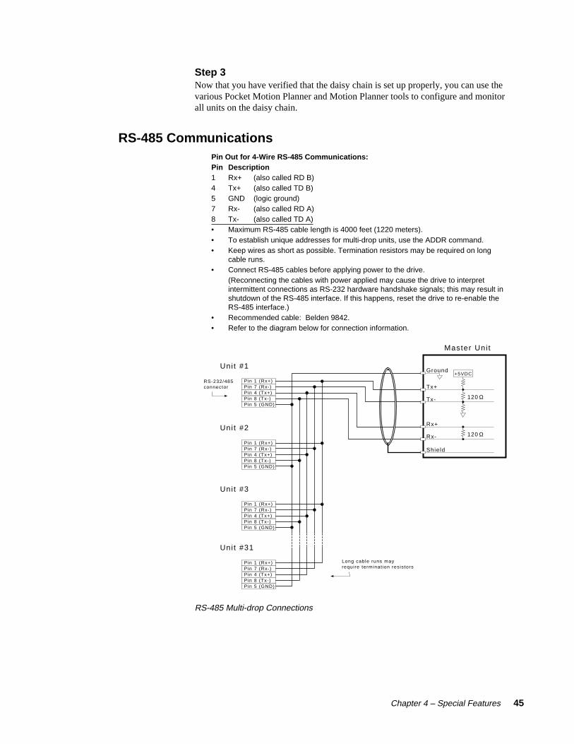
Chapter 4 – Special Features 45
Step 3Now that you have verified that the daisy chain is set up properly, you can use thevarious Pocket Motion Planner and Motion Planner tools to configure and monitorall units on the daisy chain.
RS-485 CommunicationsPin Out for 4-Wire RS-485 Communications:Pin Description1 Rx+ (also called RD B)4 Tx+ (also called TD B)5 GND (logic ground)7 Rx- (also called RD A)8 Tx- (also called TD A)• Maximum RS-485 cable length is 4000 feet (1220 meters).• To establish unique addresses for multi-drop units, use the ADDR command.• Keep wires as short as possible. Termination resistors may be required on long
cable runs.• Connect RS-485 cables before applying power to the drive.
(Reconnecting the cables with power applied may cause the drive to interpretintermittent connections as RS-232 hardware handshake signals; this may result inshutdown of the RS-485 interface. If this happens, reset the drive to re-enable theRS-485 interface.)
• Recommended cable: Belden 9842.• Refer to the diagram below for connection information.
RS-232/485connector
Long cable runs mayrequire terminat ion resistors
Master Uni t
Tx+
Tx-
Rx+
Rx-
120 Ω
120 Ω
Shield
Uni t #1
Unit #2
Unit #3
Unit #31
+5VDCGround
Pin 1 (Rx+)Pin 7 (Rx-)Pin 4 (Tx+)Pin 8 (Tx-)Pin 5 (GND)
Pin 1 (Rx+)Pin 7 (Rx-)Pin 4 (Tx+)Pin 8 (Tx-)Pin 5 (GND)
Pin 1 (Rx+)Pin 7 (Rx-)Pin 4 (Tx+)Pin 8 (Tx-)Pin 5 (GND)
Pin 1 (Rx+)Pin 7 (Rx-)Pin 4 (Tx+)Pin 8 (Tx-)Pin 5 (GND)
RS-485 Multi-drop Connections

46 Gemini GV6 Hardware Installation Guide
RS-485 Multi-DropUp to 99 Gemini drives may be multi-dropped. (See the previous drawing.)
The ADDR command allows you to establish up to 99 unique addresses. To usethe ADDR command, you must address each unit individually before it is con-nected on the multi drop. For example, given that each product is shippedconfigured with address zero, you could set up a 4-unit multi-drop with thecommands below, and then connect them in a multi drop:
1. Connect the unit that is to be unit #1 and transmit the Ø_ADDR1 command to it.
2. Connect the unit that is to be unit #2 and transmit the Ø_ADDR2 command to it.
3. Connect the unit that is to be unit #3 and transmit the Ø_ADDR3 command to it.
4. Connect the unit that is to be unit #4 and transmit the Ø_ADDR4 command to it.
If you need to replace a unit in the multi drop, send the Ø_ADDRi command to it,where “i” is the address you wish the new unit to have. For RS-485 multi-drop towork properly, each drive must have echo mode turned off (ECHOØ).
In order to prevent the collision of prompts being transmitted simultaneously fromseveral drives in response to a global command, you must configure the drives foreither error level 2 or error level 0 in multi-drop mode. This can be done asfollows:
Commands:
1_ERRLVL2 ; Set error level to 2 for unit #1
2_ERRLVL2 ; Set error level to 2 for unit #2
3_ERRLVL2 ; Set error level to 2 for unit #3
In general, to send a Gemini command from the master unit to a specific unit inthe multi-drop, prefix the command with the unit address and an underscore (e.g.,3_ERES4000 sets the encoder resolution to 4000 on unit #3). The master unit mayreceive data from a multi-drop unit. You should now verify that you can accesseach unit on the multi-drop.
Now that you have verified that the multi-drop is set up properly, you can use thevarious Pocket Motion Planner and Motion Planner tools to configure and monitorall units on the multi-drop.
Updating the Drive’s Operating System
The Gemini drive runs under an internal software operating system (firmware).The operating system was loaded into your drive during the manufacturingprocess, and under ordinary circumstances you will not need to update yourdrive’s operating system. However, because Compumotor continues to addenhancements, you may want to upgrade the operating system. You may obtain anew operating system file from the Compumotor web site, or from TechnicalSupport (see phone numbers on the inside cover of this manual).
For more information about web site downloads and update procedures, see theGemini Programmer's Reference.

Chapter 5 – Troubleshooting 47
5Troubleshooting
IN THIS CHAPTER
• LED Status
• Software Commands for Troubleshooting
• RS-232/485 Troubleshooting
• System Problems
C H A P T E R F I V E

48 Gemini GV6 Hardware Installation Guide
Troubleshooting Guidelines
If your system is not functioning properly, first try these steps.
First Troubleshooting Steps:
• Is the left LED illuminated? If not, look for problems with AC power. Also seeSystem Problems at the end of this chapter.
• Is the left LED illuminated RED? Try to enable drive by connecting pins 1 and 2 ofthe 50 pin DRIVE I/O connector, and issuing a DRIVE1 command.
• Cycle power to the drive. Cycling power clears most faults.
• Check wiring and feedback connections
If these steps do not solve your problem, follow the general troubleshootingprocedure outlined below:
General Troubleshooting Procedure
• Check the LEDs (see the chart below)
• Launch Motion Planner or Pocket Motion Planner
• Verify good RS-232/485 communications
• Save the configuration file
• Use software commands for problem identification:
TERRLG reports the last 10 error conditions
TAS reports on axis status
TASX extended reports on axis status and conditions
TCS reports codes for specific faults and warnings
• Look for non-Drive problems (problems with other parts of the system)
Detailed procedures for each of these topics are given in the rest of this chapter.
LEDs
The drive has two LEDs. The LED on the left can be red or green. The LED on theright can be yellow or green. LED illumination states, and the conditions theyindicate, are tabulated below.
Left LED Right LED(Green/Red) (Yellow/Green) Indicated Condition:
off Yellow InitializationRed (flashing) off Awaiting flash downloadRed (flashing) Yellow (flashing) Programming flash memoryRed Green Keep Alive modeGreen Green (flashing) Incoming steps (variable rate)Green Yellow/Green (flashing) Autorun modeRed off Drive not enabled; or,
Drive faultedGreen off Drive ready
Establish Communications and Verify Drive Configuration
If you cannot enable the drive, and examining LED conditions has not solved yourproblem, then establish communications with the drive and launch Motion Planneror Pocket Motion Planner. (See Chapter 2 Installation for detailed instructions onestablishing communications. Information about installing and using thesesoftware programs can be found in the Gemini Programmer's Reference.)
If you are unable to establish communications, see RS-232/485 CommunicationProblems later in this chapter.
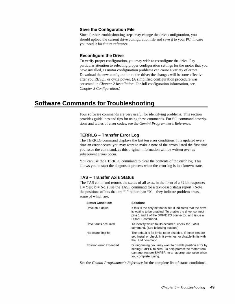
Chapter 5 – Troubleshooting 49
Save the Configuration FileSince further troubleshooting steps may change the drive configuration, youshould upload the current drive configuration file and save it to your PC, in caseyou need it for future reference.
Reconfigure the DriveTo verify proper configuration, you may wish to reconfigure the drive. Payparticular attention to selecting proper configuration settings for the motor that youhave installed, as motor configuration problems can cause a variety of errors.Download the new configuration to the drive; the changes will become effectiveafter you RESET or cycle power. (A simplified configuration procedure waspresented in Chapter 2 Installation. For full configuration information, seeChapter 3 Configuration.)
Software Commands for Troubleshooting
Four software commands are very useful for identifying problems. This sectionprovides guidelines and tips for using these commands. For full command descrip-tions and tables of error codes, see the Gemini Programmer's Reference.
TERRLG – Transfer Error LogThe TERRLG command displays the last ten error conditions. It is updated everytime an error occurs; you may want to make a note of the errors listed the first timeyou issue the command, as this original information will be written over assubsequent errors occur.
You can use the CERRLG command to clear the contents of the error log. Thisallows you to start the diagnostic process when the error log is in a known state.
TAS – Transfer Axis StatusThe TAS command returns the status of all axes, in the form of a 32 bit response:1 = Yes; Ø = No. (Use the TASF command for a text-based status report.) Notethe positions of bits that are “1” rather than “0”—they indicate problem areas,some of which are:
Status Condition: Solution:
Drive shut down If this is the only bit that is set, it indicates that the driveis waiting to be enabled. To enable the drive, connectpins 1 and 2 of the DRIVE I/O connector, and issue aDRIVE1 command.
Drive faults occurred To identify which faults occurred, check the TASXcommand. (See following section.)
Hardware limit hit The default is for limits to be disabled. If these bits areset, install or check limit switches; or disable limits withthe LHØ command.
Position error exceeded During tuning, you may want to disable position error bysetting SMPER to zero. To help protect the motor fromdamage, restore SMPER to an appropriate value whenyou complete tuning.
See the Gemini Programmer's Reference for the complete list of status conditions.

50 Gemini GV6 Hardware Installation Guide
TASX – Transfer Extended Axis StatusThe TASX command returns the axis status conditions. It reports more informa-tion than the TAS command, and is helpful for identifying which faults occurred.It returns a 32 bit response: 1 = Yes; Ø = No. (Use the TASXF command for atext-based status report.) Note the positions of bits that are “1” rather than “0”—they indicate problem areas, some of which are:
Bit #: Fault: Solution:
1 Motor temperature fault Thermal switch in motor is open; motor is hot2 Low voltage fault Check acceleration; AC power wiring and input level3 Drive temperature fault Check ventilation; ambient temperature5 Resolver failed Check resolver wiring.7 Configuration error Drive cannot operate as configured. See TCS com-
mand, below.9 Velocity error limit exceeded Check mechanics for jam; check tuning. Raise limit.10 Bridge fault Check motor wiring for short circuit. (See note below.)11 Bridge I2t fault Current model indicates bridge is hot.12 Overvoltage (bus voltage) Reduce deceleration (or install GPDM for regeneration
on GV6-U3n/U6n/U12n).18 Override mode invoked Velocity override (torque mode) or torque override
(velocity mode) was invoked. Check mechanics.(Warning only: does not light LED or stop motion.)
19 Bridge foldback Output current was reduced, to decrease dissipation.(Warning only: does not light LED or stop motion.)
20 Power Dissipation active GV6-L3n, GV6-H20n, GV6-H40n only. Internalregeneration circuit was active. Check deceleration.(Warning only: does not light LED or stop motion.)
21 Bad Hall state Bad state (111 or 000) was detected. Check Hall wiring.22 Unrecognized hardware Consult factory23 User fault Indicates user fault input was active.24 Keep Alive active Not a fault; indicates +24VDC power at +24VDC input.25 Power dissipation fault Indicates excessive regeneration (GV6-L3n, GV6-H20n,
GV6-H40n only). Check deceleration, load inertia.28 Configuration warning Drive altered a user entered value. See TCS command.
(Warning only: does not light LED or stop motion.)29 Encoder output failure ORES is set too high for maximum velocity commanded30 Motor thermal model fault Thermal model indicates motor is hot31 Torque/force is at limit Commanded torque/force has reached limit set by
DMTLIM (TTRQ = DMTLIM). Not a fault condition.
(NOTE: Bridge fault can also indicate output bridge overheating (except in GV6-L3n). To test,check drive heatsink temperature; allow drive to cool, then reset drive. If fault remains, it isdue to a short circuit—check motor and motor wiring. If fault reoccurs after several minutes, itmay be due to restricted airflow over the drive’s heatsink.)
See the Gemini Programmer's Reference for the complete list of status conditions.
TCS – Transfer Configuration StatusIf the TASX command indicates a configuration error or warning, use the TCScommand to help ascertain the cause of the condition.
NOTE: TCS reports only one error code; errors will overwrite warnings. There-fore, if there is more than one error condition present:
1. Resolve the known error.2. Cycle power to the drive, issue a RESET command, or activate the RESET input.3. If another error condition presents itself (e.g., the drive will not enable), check for
subsequent errors with the TCS command.
See the Gemini Programmer's Reference for the complete list of faults andwarnings.

Chapter 5 – Troubleshooting 51
RS-232/485 Communication Problems
If you cannot establish RS-232 or RS-485 communications, the next sections giveinstructions for procedures to help isolate problems.
Testing the COM PortInstall and launch either Motion Planner or Pocket Motion Planner. See Chapter 2Installation for information about using these software tools.
RS-232 communications require that you use a null modem cable. See Chapter 2Installation for connection instructions. Pinout diagrams for the Gemini’s RS-232/485 connector is in Chapter 4 Special Features.
Testing the COM Port with Motion PlannerIf you use Motion Planner, follow these steps.
1. Install and launch Motion Planner.
2. When the product selection dialog appears, select a Gemini drive and select theCOM port to which the Gemini is connected.
3. If you see the error message “unable to connect to com n”, then the wrong PC COMport is selected, or the PC COM port is busy.
• Check the PC COM port setting again. Your PC may have multiple COMports. Try connecting to a different port.
• Check to see if another application is busy using the COM port. Close allother applications.
• Try connecting to a different port.
• Check AC power to the drive. (The drive’s left LED should be illuminated,either red or green.)
If these steps do not solve your problem, see Testing the Cable, below.
Testing the COM Port with Pocket Motion PlannerIf you use Pocket Motion Planner, follow these steps.
1. Install and launch Pocket Motion Planner.
2. From the “Communications” menu, select “Com Port”, and select an appropriatecom port.
3. From the “Communications” menu, select “Test Com Port”.
4. You will see one of the following responses:
If the response is “Communications OK!”, then:
• communications are working properly.
If the response is “Communications problem found”, then:
• Verify the drive is powered up
• Verify the RS-232 cable is connected to the drive
• Check your com port settings within Pocket Motion Planner
• Make sure no other programs or hardware are trying to use this com port.
If these steps do not solve your problem, see Testing the Cable.

52 Gemini GV6 Hardware Installation Guide
Testing the CableUse the following two procedures to test your null modem cable, and verify that itis working properly.
“Loop Back” Test1. Connect one end of your RS-232 cable to your PC, palm PC, or HPC. Disconnect
the other end of the cable from the drive.
2. Connect pin 2 to pin 3 on the drive end of the RS-232 cable.
3. Launch Pocket Motion Planner and select “Test Com Port” from the “Communica-tions” menu.
4. If you receive a “Communications OK!” response, your cable is good.
5. Under “Tools”, select “Terminal Emulator”. Under “Options”, select “Show Hex.”
6. With pins 2 and 3 at the drive end of your null modem cable open, typing “DRES” inthe terminal will produce the response “DRES 0A00”.
7. With pins 2 and 3 at the drive end of your null modem cable shorted, typing “DRES”in the terminal will produce the response “DRES 0A00 0A00”.
If you are continuing to have trouble with communications, proceed to Verifying aNull Modem Cable.
Verifying a Null Modem Cable1. Connect one end of your RS-232 cable to your PC, palm PC, or HPC. Disconnect
the other end of the cable from the drive.
2. With no data being transmitted, measure the voltage on the RS-232 cable’s transmitpin (should be pin 2). The voltage on the transmit pin should be in the range-3VDC to -12VDC.
3. Measure the voltage on the RS-232 cable’s receive pin (should be pin 3). Thevoltage on the receive pin should be zero volts.
4. Verify that the cable’s transmit pin connects to Pin 2 on the Gemini’s RS-232/485connector.
This completes the test.
RS-232 Daisy Chain Guidelines
All drives in an RS-232 daisy chain must be configured as follows:
• Echo must be on (ECHO1)
• Error level must be set to a value greater than Ø. (See ERRLVL command).
For more information about RS-232 daisy chain problems, see RS-232/485Communications in Chapter 4 – Special Features.
RS-485 Multi-Drop Guidelines
All drives in an RS-485 multi-drop must be configured as follows:
• Echo must be off (ECHOØ)
• Error level must be set to either 2 or Ø. (See ERRLVL command).
• Connect RS-485 cables before applying power to the drive.
For more information about RS-485 multi-drop problems, see RS-232/485Communications in Chapter 4 – Special Features.
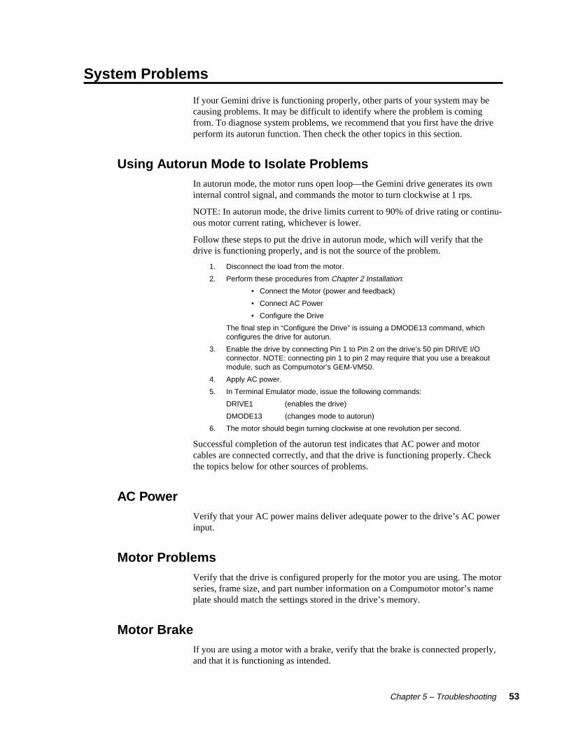
Chapter 5 – Troubleshooting 53
System Problems
If your Gemini drive is functioning properly, other parts of your system may becausing problems. It may be difficult to identify where the problem is comingfrom. To diagnose system problems, we recommend that you first have the driveperform its autorun function. Then check the other topics in this section.
Using Autorun Mode to Isolate ProblemsIn autorun mode, the motor runs open loop—the Gemini drive generates its owninternal control signal, and commands the motor to turn clockwise at 1 rps.
NOTE: In autorun mode, the drive limits current to 90% of drive rating or continu-ous motor current rating, whichever is lower.
Follow these steps to put the drive in autorun mode, which will verify that thedrive is functioning properly, and is not the source of the problem.
1. Disconnect the load from the motor.
2. Perform these procedures from Chapter 2 Installation:
• Connect the Motor (power and feedback)
• Connect AC Power
• Configure the Drive
The final step in “Configure the Drive” is issuing a DMODE13 command, whichconfigures the drive for autorun.
3. Enable the drive by connecting Pin 1 to Pin 2 on the drive’s 50 pin DRIVE I/Oconnector. NOTE: connecting pin 1 to pin 2 may require that you use a breakoutmodule, such as Compumotor’s GEM-VM50.
4. Apply AC power.
5. In Terminal Emulator mode, issue the following commands:
DRIVE1 (enables the drive)
DMODE13 (changes mode to autorun)
6. The motor should begin turning clockwise at one revolution per second.
Successful completion of the autorun test indicates that AC power and motorcables are connected correctly, and that the drive is functioning properly. Checkthe topics below for other sources of problems.
AC PowerVerify that your AC power mains deliver adequate power to the drive’s AC powerinput.
Motor ProblemsVerify that the drive is configured properly for the motor you are using. The motorseries, frame size, and part number information on a Compumotor motor’s nameplate should match the settings stored in the drive’s memory.
Motor BrakeIf you are using a motor with a brake, verify that the brake is connected properly,and that it is functioning as intended.

54 Gemini GV6 Hardware Installation Guide
Motor ResolverResolvers on Compumotor motors are aligned at the factory. Ordinarily, no furtheralignment is necessary. However, if you suspect that the resolver has been alteredand is out of alignment, you can follow the alignment procedure in Aligning theResolver, located in Chapter 4 Special Features.
Mechanical System
Shaft CouplerVerify that the shaft coupler is not slipping during acceleration or deceleration. Werecommend bellows or disk style couplers for servo applications. Helical couplersare inadequate, and are not recommended.
Mechanical TransmissionVerify that your mechanical system functions properly, and is not jammed.
Motion ProblemsIf problems occur during motion, check these possible causes:
• Motor Sizing (ensure that the motor has enough torque to perform the move)
• Excessive Acceleration or Deceleration
• Excessive Velocity
Electrical NoiseElectrical noise on input or output lines can cause stop or kill inputs to activateunexpectedly. See Appendix C: Regulatory Compliance for installation guidelineson reducing electrical noise.
Software/Motion Program ProblemsCheck to see that your motion programs are functioning properly, and are notcausing unexpected problems.

Appendix A – Specifications 55
ASpecifications
IN THIS CHAPTER
• Gemini Drive Specifications
• Input/Output Specifications
• Dimensions
• Protective Circuits
• Cable Specifications
A P P E N D I X A

56 Gemini GV6 Hardware Installation Guide
Power Specifications
+24VDC Input Power (Optional “Keep Alive” Power)Input voltage range: 19.2 – 28.8 VDCInput current: 500 mA (minimum)
AC Input Power
ACDrive AC Input VoltageGV6-L3n 95VAC – 132VAC, 1-phase, 50/60 HzGV6-U3n 95VAC – 264VAC, 1-phase, 50/60 HzGV6-U6n 95VAC – 264VAC, 1-phase, 50/60 HzGV6-U12n 95VAC – 264VAC, 1-phase, 50/60 HzGV6-H20n 165VAC – 264VAC, 1-phase or 3-phase, 50/60 HzGV6-H40n 165VAC – 264VAC, 3-phase, 50/60 Hz
CAUTION
Do not operate GV6-L3 above 132VAC, or the drive will be permanently damaged.
Connector: GV6-L3/U3/U6/U12/H20: GV6-H40:Drive terminals: #8 (M4) screw terminals #10 (M5) screw terminalsMating terminals: spade fork, 0.325” max. width ring terminal, 0.25” I.D., 0.50” O.D.Tightening torque: 20 in-lbs nom., 24 in-lbs max. 20 in-lbs nom., 24 in-lbs max.
Output PowerContinuous Output: Peak Output:Current Power Current Power
Drive (amps, peak) (watts, max) (amps, peak) (watts, max)GV6-L3n 3A 440W 7.5A 1.1 kWGV6-U3n 3A 880W 7.5A 2.2 kWGV6-U6n 6A (at 8 kHz) 1.75 kW 15A (at 8 kHz) 4.4 kWGV6-U12n 12A (at 8 kHz) 3.5 kW 30A (at 8 kHz) 8.8 kWGV6-H20n 20A (3∅ input 5.8 kW 50A (3∅ input) 14.7 kW
at 8 kHz) at 8 kHz)GV6-H40n 40A (3∅ input 11.8 kW 100A (3∅ input) 29.4 kW
at 8 kHz) at 8 kHz)
Connector: GV6-L3/U3/U6/U12/H20: GV6-H40:Drive terminals: #8 (M4) screw terminals #10 (M5) screw terminalsMating terminals: spade fork, 0.325” max. width ring terminal, 0.25” I.D., 0.50” O.D.Tightening torque: 20 in-lbs nom., 24 in-lbs max. 20 in-lbs nom., 24 in-lbs max.
Amplifier
Type: GV6-L3n: 40 kHz PWM; 3 phases
GV6-U3n: 8 kHz PWM; 3 phases
GV6-U6n/U12n/H20n/H40n: 8, 16, 20 kHz PWM; 3 phases
Performance
Accuracy: ±1 encoder count; encoder dependent

Appendix A – Specifications 57
Environmental Specifications
GV6-L3n;GV6-U3n/U6n/U12n;GV6-H20n (with< 25W regen); GV6-H20n (withGV6-H40n <100W regen)
Operating Temperature: Still Air: 45°C (113°F) 35°C (95°F)Moving air: 50°C (122°F) 40°C (104°F)Minimum: 0°C (32°F) 0°C (32°F)
Storage Temperature: -40°C – 85°C (-40°F – 185°F)
Humidity: 0 – 95%, non-condensing
Shock: 15g, 11msec half sine
Vibration: 10 – 2000 Hz at 2g
Standards
UL, cUL 508C
CE for LVD 72/23/EEC
BS EN61010-1:1993/A2:1995 (ie includes 1995 amendment AMD 8961)Safety requirements for electrical equipment for measurement, control,and laboratory use Part 1. General requirements
CE for EMC 89/336/EEC
BS EN61800-3: 1997 Adjustable speed electric power drive systemsPart 3. EMC product standard includingspecific test methods.
IEC 61800-3: 1996 Adjustable speed electric power drive systemsPart 3. EMC product standard includingspecific test methods.
Interface/Communication
Connector:Drive connector: 9 pin D-subminiature plug.Mating connector: 9 pin D-subminiature receptacle
RS-232: RS-485*:Rx, Tx, Gnd 4-wire plus ground (Rx+, Rx-, Tx+, Tx-, Gnd)9600 baud 9600 baud8 data bits 8 data bits1 stop bit 1 stop bitno parity no parityfull duplex full duplex
*twisted pair cabling recommended (e.g. Belden 9842)
Weight
WeightDrive pounds (kg)
GV6-L3n: 4.3 (1.9)GV6-U3n: 4.3 (1.9)GV6-U6n: 5.0 (2.3)GV6-U12n: 5.0 (2.3)GV6-H20n: 9.0 (4.1)GV6-H40n: 16.1 (7.4)

58 Gemini GV6 Hardware Installation Guide
Inputs and Outputs
This section describes all inputs and outputs (I/O) located on the 50 pinDRIVE I/O connector. The connector pinout is shown in the next drawing.
Output GroundOutput 6Output 5
Output GroundOutput 4Output 3
Output GroundOutput 2
Output GroundOutput 1
Input GroundInput 8Input 7Input 6
Input GroundInput 5Input 4
CNTRL-P: Inputs 4, 5, 6, 7, 8Input Ground
Input 3Input Ground
Input 2Input 1
CNTRL-P: Inputs 1, 2, 3VINref
Analog GroundAnalog Input–Analog Input+Analog Output BAnalog Output ADigital GroundEncoder Out Z–Encoder Out Z+Encoder Out B–Encoder Out B+Encoder Out A–Encoder Out A+ReservedReservedReservedReservedReservedReservedDigital GroundDigital Ground+5VDC Output+5VDC OutputResetDigital GroundEnable
25242322212019181716151413121110987654321
25242322212019181716151413121110987654321
50494847464544434241403938373635343332313029282726
Inputs
Outputs
AnalogOutputs (2)
Analog Input
Reset &Enable
Encoder Out
Connector Pinout
Drive I/O Connector
Connector Specifications:Mating Connector*
Gemini Drive: (not provided; see note):
Manufacturer: AMP AMP
Connector Type: CHAMP .050 Series II CHAMP .050 Series II
AMP Part Number: 2-178238-7 2-175677-7
Wire Gauge: not applicable use 28 AWG (0.08 mm2)
* Note: Mating connectors are not provided with Gemini drives; Compumotor cables areavailable with mating connectors attached. If you make your own cables, you must use a“jack screw” style fastener, not “spring clip” style. The mating connector listed above isan insulation displacement connector (IDC), intended for use with molded cables.
Soldercup ConnectorThe soldercup connector and plastic screw lock backshell listed below will fit onto theGemini’s DRIVE I/O connector. Because the backshell is plastic, it should not be used inCE applications.
Connector Type: Soldercup Connector Screw Lock Backshell
Manufacturer: 3M 3M
3M Part Number: 10150-3000VE 10350-52A0-008

Appendix A – Specifications 59
Enable Input (required)To enable the drive and energize the motor, you must connect the enable input(pin 1) to digital ground (pin 2), and issue a DRIVE1 command. The next drawingshows the internal circuit.
Internal Connections
Same circuit design as Enable
VINref
EnableDigital GroundReset
26
123
DRIVE I/O Connector
+24V
6.81 KΩ
10 KΩ
20.0 KΩ
18.2 KΩ
12.0 KΩ
33.0 KΩ
33.0 KΩ
-
+
ThresholdSense
Inputs internally pulled up to +24V, unless you connect an external 5 – 24VDC supply to the VINref terminal.
Input voltage range: 0 – 24VDC.Switching Levels: Low ≤ 1/3 VINref voltage High ≥ 2/3 VINref voltageActive Level: Active low
Optional normally closed switch, recommended for manual disable.
+5V
250 mAmaximum source
+5VDC Output+5VDC Output
45
Enable Input and Reset Input
Reset Input (optional)The reset and enable inputs use the same circuit design, as the drawing aboveindicates.
To reset the drive, temporarily connect the reset input (pin 3) to digital ground(pin 2). Reset begins when pin 3 is grounded. The drive will begin its power upsequence upon disconnection of pin 3 from ground.
VINref – Voltage Input Reference (optional)Use VINref (pin 26) to set the input reference voltage for the enable, reset, anddigital inputs.
It is not necessary for you to make connections to VINref. If you connect nothing,then the enable, reset, and inputs are internally pulled up to +24VDC. This is thefactory default condition.
If you connect an external 5 – 24VDC power supply to VINref, then the inputswitching thresholds become:
Low ≤ 1/3 ∗ VINrefHigh ≥ 2/3 ∗ VINref(Default:, with VINref at internal +24VDC: Low < 8V, High > 16V)
+5VDC Output (optional)A +5VDC output (pins 4 & 5) can provide up to 250 mA. The output is shortcircuit protected.

60 Gemini GV6 Hardware Installation Guide
Digital Inputs (optional)The Gemini drive has eight digital inputs. All connections are shown in the nextdrawing. Defaults are shown in parentheses, but you can use the INFNC commandto redefine the function of any of the inputs. See the Gemini Programmer'sReference for more information.
By default, these are +24VDC sourcing inputs. You can use VINref (pin 26) tochange the switching voltage level. You can also use CNTRL-P (pins 27 and 33)to change the inputs from sourcing to sinking inputs.
Internal Connections
Same circuit design as Input 1
VINref
Input 1 (Pos limit)Input 2 (Neg limit)Input GroundInput 3 (Home)Input GroundInput 4 (Trigger)Input 5Input GroundInput 6Input 7Input 8Input Ground
DRIVE I/O Connector
+24V
CNTRL-P: 1 – 3CNTRL-P: 4 – 8
26
282930313234353637383940
2733
6.81 KΩ
20.0 KΩ
18.2 KΩ
12.0 KΩ
33.0 KΩ
33.0 KΩ
-
+
Same circuit design as CNTRL-P: 1 – 3
Inputs internally pulled up to +24V, unless you connect an external 5 – 24VDC supply to the VINref terminal.
Inputs are sourcing at +24V, unless you connect CNTRL-P to ground; then inputs will be sinking inputs.
Input voltage range: 0 – 24VDC.Switching Levels: Low ≤ 1/3 VINref voltage High ≥ 2/3 VINref voltage
10 KΩ
10 KΩ
ThresholdSense
Pullup/DownSense
Inputs
You can use the INLVL and INDEB commands to configure the inputs as activehigh or active low, and to set the debounce time, respectively.
CNTRL-P – Reference for Digital Inputs (optional)Use CNTRL-P (pins 27 and 33) to change the digital inputs from sourcing inputsto sinking inputs.
It is not necessary for you to make any connections to CNTRL-P. If you connectnothing, then the inputs are internally pulled up to VINref. If sourcing inputs areappropriate for your application, then make no connections to CNTRL-P.
If you connect CNTRL-P to digital ground, then the inputs will become sinkinginputs, and will sink current.

Appendix A – Specifications 61
Digital Outputs (optional)The Gemini drive has six digital outputs. All connections are shown in the nextdrawing. Defaults are shown in parentheses, but you can use the OUTFNCcommand to redefine the function of any of the outputs. See the GeminiProgrammer's Reference for more information.
Internal Connections
41 Output 1 (General purpose)42 Output Ground43 Output 2 (Drive fault)44 Output Ground45 Output 3 (At limit)46 Output 4 (Position error)47 Output Ground48 Output 5 (Moving/not moving)49 Output 6 (General purpose)50 Output Ground
DRIVE I/O Connector
Open Collector,300mA sinkcapability
Do not applymore than 30VDC
Same circuit design as Output 1
Outputs
You can use the OUTLVL command to configure each of the outputs as activehigh or active low.
Encoder Output (optional)Pins 14 – 19 are encoder outputs.
Encoder Output Specifications:
Default Resolution: Quadrature outputs
4000 counts per revolution, post quadrature
Clockwise Rotation: Channel A leads Channel B
Counterclockwise Rotation: Channel B leads Channel A
The encoder outputs operate in one of two modes:
Pseudo Encoder Mode:Output Channels A and B are derived from position information from the loadfeedback device (e.g. encoder or resolver). The outputs are not based on calculatedor commanded position. Pseudo encoder mode is the default mode, unless allconditions listed below are satisfied. There is no Channel Z output in pseudoencoder mode.
Pass Through Encoder Mode:If the following conditions are satisfied, then Channels A, B, and Z are “passedthrough” the drive, from the feedback device (e.g. encoder or resolver) to theencoder outputs.
Required Conditions using an Encoder as Feedback Device
1. ERES and ORES values are equal.
Required Conditions using a Resolver as Feedback Device
1. Resolver is selected as the feedback device (SFB command).
2. ERES is set to 4096.
3. ORES is set to 4096.
If any of these conditions is not satisfied, then the outputs will operate in pseudoencoder mode.

62 Gemini GV6 Hardware Installation Guide
The encoder output circuit is shown in the next drawing.
Internal Connections
14 Encoder Out A+15 Encoder Out A-16 Encoder Out B+17 Encoder Out B-18 Encoder Out Z+19 Encoder Out Z-20 Digital Ground
DRIVE I/O Connector
From DSP(or passed through if required conditions met)
From DSP(or passed through if required conditions met)
AM26LS31
AM26LS31
Passed Through(if required conditions are satisfied)
AM26LS31
Encoder Outputs
You can use the ORES command to configure the encoder outputs.
Analog Monitor (optional)Two analog monitor outputs are available on pins 21 and 22. Use pin 25 as aground reference for these monitors.
Analog Monitor Specifications:
Maximum Output: ±10V (scalable; use DMON command)
Resolution: 8 bits peak to peak (for full scale signal)
Internal Connections
21 Analog Monitor A22 Analog Monitor B23 24 25 Analog Ground
DRIVE I/O Connector
221 Ω
User configurableoutput variable
-
+
Same circuit design asAnalog Monitor A
Analog Monitors
You can configure the analog outputs to monitor many different variables, such ascurrent, velocity, temperature, etc. You can also scale the outputs. See the DMONcommands in Chapter 3 Configuration and the Gemini Programmer's Referencefor more information.
WARNING
Do not use Analog Monitors as control signals. Because of offsets, limited resolu-tion and accuracy, use the analog monitor outputs only for oscilloscope monitoring.

Appendix A – Specifications 63
Analog Input (optional)An analog input is available on pins 23 and 24. Use pin 25 as a ground referencefor the analog input.
Connection Instructions for the Analog Input:
1. Connect Analog Input+ to pin 23.
2. Connect Analog Input- to pin 24.
3. Connect your analog source’s ground reference to pin 25.
These connections are illustrated in the next drawing.
Internal Connections
Analog Input+ (±10V)Analog Input- (±10V)Analog Ground
DRIVE I/O Connector
95KΩ
95KΩ
20KΩ
20KΩ
232425
-
+
Analog Input
See the TANI and VARI commands in the Gemini Programmer's Reference formore information about using the analog input.

64 Gemini GV6 Hardware Installation Guide
Feedback Devices
This section describes inputs for encoder feedback, resolver feedback, motorthermal switch, and Hall effects located on the drive’s 26 pin MOTOR FEED-BACK connector. The next drawing shows the pinout of the connector.
Connector Pinout
Cos–Cos+Sin–Sin+
ReservedReserved
Ref 1–Ref 1+Hall CHall BHall A
Hall GroundHall +5V
Thermal SwitchThermal SwitchDigital GroundEncoder Z–Encoder Z+Encoder B–Encoder B+Encoder A–Encoder A+Encoder GroundEncoder GroundEncoder +5VEncoder +5V
13121110987654321
26252423222120191817161514
Hall Effects
Resolver
Encoder
Thermal Switch
Motor Feedback Connector
Connector Specifications:Mating Connector*
Gemini Drive: (not provided; see note):
Manufacturer: AMP AMP
Connector Model: CHAMP .050 Series II CHAMP .050 Series II
AMP Part Number: 2-178238-4 2-175677-4
Wire Gauge: not applicable use 28 AWG (0.08 mm2)
* Note: Mating connectors are not provided with Gemini drives; Compumotor cables areavailable with mating connectors attached. If you make your own cables, you must use a“jack screw” style fastener, not “spring clip” style. The mating connector listed above isan insulation displacement connector (IDC), intended for use with molded cables.
Soldercup ConnectorThe soldercup connector and plastic screw lock backshell listed below will fit onto theGemini’s MOTOR FEEDBACK connector. Because the backshell is plastic, it should notbe used in CE applications.
Connector Type: Soldercup Connector Screw Lock Backshell
Manufacturer: 3M 3M
3M Part Number: 10126-3000VE 10326-52A0-008

Appendix A – Specifications 65
EncoderIf you use a motor with encoder feedback, connect your encoder to pins 1 – 10, asshown in the figure below.
681Ω
Internal Connections
681Ω 681Ω
Same circuit as Encoder A+/A–
Encoder +5VEncoder +5VEncoder GroundEncoder GroundEncoder A+Encoder A–Encoder B+Encoder B–Encoder Z+Encoder Z-
123456789
10
MOTOR FEEDBACK Connector
+5V
250 mA maximum:Encoder +5V and Hall +5V combined
Encoder Input Connections
Because the wire used in many encoder cables is very thin, we provide two pinsfor encoder +5VDC (pins 1 and 2) and for encoder ground (pins 3 and 4). Connecttwo wires in your encoder cable to the +5VDC pins, and connect two wires to theencoder ground pins. We recommend that you splice each pair of wires to a largerdiameter wire, as shown in the next drawing.
Encoder Cable
Encoder +5Encoder +5Encoder GroundEncoder Ground
1234
To Encoder
MOTOR FEEDBACK Connector
Splice wire pair to thicker gauge wire
Splicing Wires Together
Splicing to a larger wire provides more wire for current conduction, minimizingvoltage drop at the encoder. (Gemini motor feedback cables use this technique.)
ResolverIf you use a motor with resolver feedback, connect the resolver to pins 19 – 26, asshown in the figure below.
Internal Connections
Ref 1+Ref 1–ReservedReservedSin+Sin–Cos+Cos–
1920212223242526
MOTOR FEEDBACK Connector
4.25V rms ±5%at 7kHz ±5%(sine wave)
To RDCSin± and Cos±input voltage: 2V rms ±5%
To RDC
Resolver Input Connections

66 Gemini GV6 Hardware Installation Guide
Motor Thermal Switch Connections (optional)Connect your motor’s thermal switch wires to pins 12 and 13 on the MOTORFEEDBACK connector.
The drive checks for electrical continuity between pins 12 and 13. This continuityis usually provided by a normally-closed thermal switch mounted on the motor. Ifthe motor overheats and the thermal switch opens, the loss of continuity triggersprotection circuitry in the Gemini drive. The drive will turn off power output to themotor, illuminate the left LED red, and set the motor fault and drive fault bits. Youcan monitor the fault bits with the TAS and TASX commands.-To resume operations after the motor cools and its thermal switch closes, cyclepower or issue a DRIVE1 command.
If your motor does not have a thermal switch, short pins 12 and 13 together. Thedrive will experience a motor fault if neither a thermal switch nor a jumper wire isattached to pins 12 and 13.
Hall EffectsConnect your motor’s Hall effect wires to pins 14 – 18 on the MOTOR FEED-BACK connector.
The Gemini GV6 drive is designed to be used with motors that have single-ended,open collector Hall outputs. Internally, the drive pulls these signals up to +5V. TheHall effect circuit is shown below.
Internal Connections
1KΩ10KΩ
Same circuit as Hall A
Hall +5Hall GroundHall AHall BHall C
1415161718
MOTOR FEEDBACK Connector
+5V250 mA maximum:Encoder +5V and Hall +5V combined
Hall Effect Connections
The Gemini drive uses the Hall effect inputs to synchronize the encoder with themotor’s internal magnets at the start of motion. Initial commutation is trapezoidal;once the drive establishes synchronization it changes to sinusoidal commutationbased on encoder position.
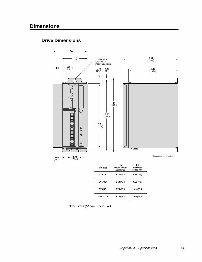
Appendix A – Specifications 67
Dimensions
Drive Dimensions
6.00(153.0)
5.40(138.0)
3.13 (79.4) 0.38 (9.5)GV6-L3n
3.13 (79.4) 0.38 (9.5)GV6-U3n
3.75 (95.3) 1.00 (25.4)GV6-U6n
3.75 (95.3) 1.00 (25.4)GV6-U12n
OW
2.75(70)
1.38(35)FH
7.0(177.8)
7.75(196.9)
8.0(203.2)
1.00(25.4 )
0.88(22.2)
ProductOW
Overall Widthinches (mm)
FHFin Height
inches (mm)
3x clearancefor #8 or M4mounting screws
Dimensions in inches (mm)
0.58(14.7)
0.16(4.1)
Dimensions (Shorter Enclosure)

68 Gemini GV6 Hardware Installation Guide
6.00(153.0)
5.40(138.0)
2.75(70)
5.0(127)
1.38(35)
2.25(57.2)
8.9(226.1)
9.63(244.5)
9.9(251.5)
1.00(25.4 )
0.88(22.2)
Dimensions in inches (mm)
3x clearancefor #8 or M4mounting screws
0.58(14.7)
0.16(4.1)
Dimensions – GV6-H20n
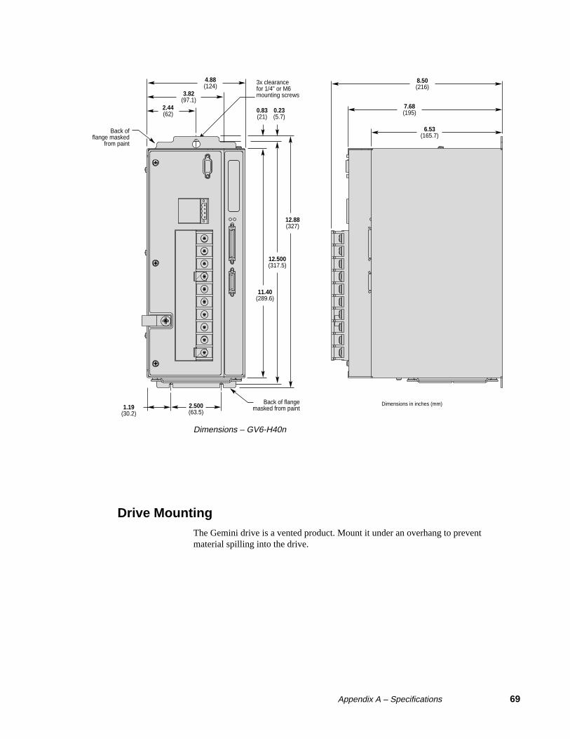
Appendix A – Specifications 69
8.50(216)
7.68(195)
6.53(165.7)
11.40(289.6)
0.83(21)
0.23(5.7)
12.500(317.5)
12.88(327)
2.500(63.5)
1.19(30.2)
Back of flangemasked from paint
Back offlange masked
from paint
3.82(97.1)
4.88(124)
2.44(62)
3x clearancefor 1/4" or M6mounting screws
Dimensions in inches (mm)
Dimensions – GV6-H40n
Drive MountingThe Gemini drive is a vented product. Mount it under an overhang to preventmaterial spilling into the drive.

70 Gemini GV6 Hardware Installation Guide
Panel Layout Dimensions
1.00(25.4 )
1.00(25.4 )MinimumClearance
1.00(25.4 )MinimumClearance
1.00(25.4 )MinimumClearance
0.50(12.7)MinimumClearance
1.00(25.4 )MinimumClearance
NOTE: Provide proper spacing to maintain minimum clearance between drives.
NOTE: Provide proper spacing to maintain minimum clearance between drives.
Panel Layout: GV6-L3n GV6-U3n GV6-U6n GV6-U12n
Panel Layout Dimensions – GV6-L3n, GV6-U3n/6n/12n

Appendix A – Specifications 71
1.00(25.4 )
2.00(50.8 )MinimumClearance
0.50(12.7)MinimumClearance
0.50(12.7)MinimumClearance
0.50(12.7 )MinimumClearance
1.00(25.4 )MinimumClearance
NOTE: Provide proper spacing to maintain minimum clearance between drives.
NOTE: Provide proper spacing to maintain minimum clearance between drives.
NOTE: Vertical spacing between drives:8 in. (200 mm) for GV6-H40operating at full power;6 in. (150 mm) for GV6-H20operating at full power;4 in (100 mm) otherwise.
Panel Layout:
GV6-H20n GV6-H40n
(shown below)
Dimensions in inches (mm)
Panel Layout Dimensions – GV6-H20n and GV6-H40n

72 Gemini GV6 Hardware Installation Guide
Protective Circuits
Short Circuit ProtectionThe Gemini drive has an internal circuit that protects it from short circuits betweenone motor terminal to another (phase to phase), or from any motor terminal toearth. A short circuit fault is a latched fault.
Short circuit fault caused by: Phase to phase short circuitPhase to earth short circuit
Results of Fault: Power to motor is turned OFFLEDs: Left = illuminated RED; Right = offFault output is activatedLatched fault
Inrush Current ProtectionThe Gemini drive has internal circuitry that protects it from high inrush currentwhen power is initially applied to the drive. The circuitry works automatically.
Inrush Current Current limiter bypassedDrive Limiter (ohms): with shorting relay:GV6-L3n 5Ω yesGV6-U3n 10Ω yesGV6-U6n 10Ω yesGV6-U12n 10Ω yesGV6-H20n 10Ω yesGV6-H40n 20Ω yes
The shorting relay removes the inrush current limiter after drive startup. Thisallows maximum bus voltage during high acceleration/peak torque/maximumspeed applications.
Inrush current is temperature dependent:
Ambient Temperature: Inrush Current Limit:
25°C (77°F) less than 35 amps
50°C (122°F) less than 70 amps
Drive Overtemperature ProtectionThe Gemini drive’s overtemperature circuit monitors the drive’s internal tempera-ture sensors. If the sensors exceed the threshold temperature, the drive issues anovertemperature fault.
Threshold Temperature: All drives except GV6-H20n: 80°C (176°F)
GV6-H20n: 90°C (194°F)
Results of Fault: Power to motor is turned OFF
LEDs: Left = illuminated RED; Right = off
Fault output is activated
Latched fault
Motor Overtemperature ProtectionThe Gemini drive has two motor overtemperature circuits:
Hardware Switch: a thermal switch is embedded in Compumotor motor windings
I2t Thermal Model: the drive’s internal operating software predicts motor windingtemperature, based on motor parameters.

Appendix A – Specifications 73
Undervoltage ProtectionThe Gemini drive’s undervoltage protection circuit monitors AC input voltage. Ifthe voltage falls below 75VAC while the drive is operating (85VAC for GV6-H20), the drive issues an undervoltage fault and turns off power to the motor.
Undervoltage protection has the following features:
Threshold Voltage: Voltage falling below 75VAC trips fault(85VAC for GV6-H20n)
Results of Fault: Power to motor is turned OFFLEDs: Left = illuminated RED; Right = offFault output is activatedLatched fault
Overvoltage ProtectionThe Gemini drive’s overvoltage circuit protects the drive from excessive regenera-tion. If the voltage on the motor output terminals rises above the threshold voltage,the drive disables its output terminals, and the motor will freewheel.
Threshold Voltage: GV6-L3n: 212VDCGV6-U3n/6n/12n/H20n/H40n: 410VDC
Results of Fault: Power to motor is turned OFFLEDs: Left = illuminated RED; Right = offFault output is activatedLatched fault
CAUTION
Overvoltage protection monitors only the motor output terminals (DC motor bus). Itdoes not protect against an overvoltage on the AC input terminals.
Current FoldbackThe GV6 drive’s current foldback circuit helps to protect the motor from damagedue to prolonged high currents.
If your drive is operating above its continuous rating, use the figure below topredict the number of seconds until foldback will occur. For example, the figureshows that at the drive’s peak current rating (250% of continuous), foldback willoccur after six seconds.
1 10 100 10 3 10 40
Peak Rating = 250 %
150 %
200 %
Continuous Rating = 100 %
50 %
Time (seconds)
Drive Current Rating vs. Time
Time Until Foldback
See Chapter 3 Configuration for more information on how to configure the currentfoldback circuit to protect your motor.

74 Gemini GV6 Hardware Installation Guide
Cable Specifications
This section contains specifications for Compumotor cables and cabling accesso-ries you can use with Gemini drives.
CE CablesMany Compumotor cables are CE Cables. If installed according to instructions inAppendix C – Regulatory Compliance: UL and CE, these cables are designed toaid the user in gaining European Compliance, and are thus an integral part of a CEsystem solution. CE cables add RF screening and bonding to reduce emissions,and provide high integrity safety Earth bonding. They also help to reduce prob-lems in high electrical noise environments.
Non-CE CablesCompumotor also offers non-CE cables, for applications where CE compliance isnot required, and where ambient electrical noise does not cause problems. Becausethese cables are either unshielded, or contain simple foil shielding terminated by adrain wire, they do not provide significant shielding of electrical noise at highfrequencies.
To help you select the correct cables for your application, see Compumotor’sTechnical Bulletin TB269: Proper Cable Selection – CE vs. Non-CE GeminiApplications.
Gemini 50 Pin Connector to 50 Pin D-Connector CableUse this cable to connect the Gemini drive’s 50 pin DRIVE I/O connector to the50 pin D-connector on the Gemini 50 pin breakout module (GEM-VM50).
CE Cable: Part Number 71-016945-03
This cable has the same pinout and color code as the flying lead cable; instead offlying leads, it has a 50 pin D-connector on the end.
Gemini GEM-VM50 – 50 Pin Breakout ModuleUse the 50 pin breakout module for access to individual terminals on the 50 pinconnector. The GEM-VM50 includes the cable above.
Description: Part Number:
50 pin Breakout Module (with Cable) GEM-VM50
50 pin Breakout Module (without cable) 01-016986-01
Null Modem Cable – 9 Pin D-Connector to 9 Pin D-ConnectorUse this cable for RS-232 communications between the Gemini drive and aterminal. Note that this is not a “straight-through” cable; pins 2 and 3 are crossed,making it a “null-modem” cable.
CE Cable: Part Number 71-016939-10
Connector: 9 pin female D-subminiature connector on each end

Appendix A – Specifications 75
Shield
BlackRed
Green
Yellow
GrayBrownBlueViolet
Red
GrayBrownBlueViolet
White
Orange
White
Orange
Red
N/C
N/C
N/CN/CN/CN/CN/C
x
xxxxx
x
x
x
x
Black
Green
Yellow
563
2
17489
562134789
Cable – RS-232 Null Modem
Gemini 50 Pin Connector to Flying Leads CableUse this cable to connect an external device to the Gemini drive’s 50 pinDRIVE I/O connector.
CE Cable: Part Number 71-016943-10 10 ft. (3 m) in length
Non-CE Cable: Part Number 71-019861-04 4 ft. (1.2 m) in length; and 71-019861-10 10 ft. (3 m) in length
The next drawing shows the color code for this 50 pin connector/flying lead cable.Note that the CE and non-CE cables have different color codes.
Shield
White/VioletWhite/GrayRed/Black
White/Black/OrangeWhite/Black/Green
Green/Black
Yellow/RedGray/Blue
Yellow/GreenGray/Orange
Blue/RedBlue/Orange
GrayPink
White/PinkOrange/Black
White/Black/BlueYellow/Blue
Yellow/OrangeBlue/Yellow
VioletWhite/Black/Red
Yellow/BlackWhite/Black/Yellow
Blue/BlackGreen/RedGray/GreenGray/White
Yellow/WhiteBlue/WhiteGray/Brown
Yellow/Brown
Red 16 AWG
Black 16 AWG
BlackWhite/Black
RedWhite/Red
GreenWhite/Green
OrangeWhite/Orange
BlueWhite/Blue
YellowWhite/Yellow
BrownWhite/Brown
BlackWhite/Black
RedWhite/Red
GreenWhite/Green
OrangeWhite/Orange
BlueWhite/Blue
YellowWhite/Yellow
BrownWhite/Brown
123456789
1011121314151617181920212223242526272829303132333435363738394041424344454647484950
CE CABLE: 71-016943-10Non-CE CABLE: 71-019861-04 71-019861-10
Drain & Braid
* 20, 30, 31 shown out of sequence
VioletWhiteRedBlackRedOrangeBlackBlueBlackWhiteRedWhiteGreenBlackOrangeWhiteBlueWhiteYellowWhiteGreenBrownOrangeBlackGreenWhiteYellowBrownBrownWhiteGrayWhiteBrownOrangeYellowBlackBlueBrownVioletBrownVioletBlackBrownBlackGrayBrownBlackGrayRedBrown
123
*20456789
101112131415161718192122232425
*31262728
*302932333435363738394041424344454647484950
EnableDigital Ground
Reset+5VDC Output+5VDC OutputDigital GroundDigital Ground
Step+/CW+/AX+Step-/CW-/AX–
Dir+/CCW+/BX+Dir-/CCW-/BX–
ZX+ZX–
Encoder Out A+Encoder Out A–Encoder Out B+Encoder Out B–Encoder Out Z+Encoder Out Z–
Digital GroundAnalog Output AAnalog Output B
Analog Input+Analog Input–
Analog GroundVINref
CNTRL-PInput 1Input 2
Input GroundInput 3
Input Groundreservedreservedreserved
Input Groundreservedreservedreserved
Input Groundreserved
Output GroundOutput 2
Output GroundOutput 3Output 4
Output Groundreservedreservedreserved
Cable – Flying Leads (color code for CE and non-CE cables)

76 Gemini GV6 Hardware Installation Guide
Gemini GC-26 and GC-50 ConnectorsTwo breakout modules are available that connect directly to the Gemini’sMOTOR FEEDBACK and DRIVE I/O connectors.
NOTE: These modules are recommended for system prototyping only—not forpermanent installation.
Description: Part Number:
26 pin Connector/Breakout Module GC-26
50 pin Connector/Breakout Module GC-50
Dimensions are shown below.
CAUTION
Connect wires to the GC-26 and GC-50 before installing in the drive. This will avoiddamage that may be caused by wiring the connector while attached to the drive.
Dimensions in inches (millimeters)
GC-50
1 2 4
1918 20 21 22 302423 2625 2827 29 343231 33
131210 11 171614 15953 86 7
35 3736 3938 474140 4342 4544 46S 4948 50
3.05 (77.5)
2.1
3 (5
4.0)
0.138 (3.5)
1S 2 4 131210 11953 86 7
14 1615 1817 262019 2221 2423 25S
2.50 (63.5)
1.61
(40
.9)
0.138 (3.5)
GC-26
GC-26 and GC-50 Dimensions
Gemini 26 Pin Feedback Connector KitA cable connector backshell kit is available from Compumotor. The kit includesplug, cover, and all parts necessary to assemble the connector. It also includesspade lugs to install on the motor cable. The part number is:
GFB-KIT
The plug mates with the drive’s 26 pin MOTOR FEEDBACK connector.

Appendix B – Non-Compumotor Motors 77
BUsingNon-Compumotor
Motors
IN THIS CHAPTER
• Commands for Motor Configuration
• Motor Requirements
A P P E N D I X B

78 Gemini GV6 Hardware Installation Guide
Using Non-Compumotor Motors
If you use a non-Compumotor motor, you must configure the drive for your motorby setting values for all commands in the following table. Also see the MotorParameters table on the Motion Planner CD-ROM for examples of recommendeddrive configuration settings for Compumotor motors.
Commands for Motor Configuration
Command: Description:
ERES encoder feedback resolution; counts per revolution, post-quadrature
DMTIC continuous current; amps – rms, 40°C (104°F)
DMTICD continuous current derating; percent
DMTKE voltage constant; V/krpm
DMTRES line-to-line resistance; at 25°C (77°F)
DMTJ rotor inertia; kg-m2*10-6
DPOLE number of pole pairs
DMTW rated speed; revolutions per second
DMTIP peak current; amps rms
DMTLMN minimum line-to-line inductance; mH
DMTLMX maximum line-to-line inductance; mH
DMTD motor damping; nM/rad/sec
DMTRWC winding to case thermal resistance; °C/watt
DMTTCM motor case thermal time constant; minutes
DMTTCW motor winding thermal time constant; minutes
DPWM PWM switching frequency
DMTMAX motor maximum temperature
Use Motion Planner or Pocket Motion Planner to enter these command settingsinto the drive’s memory. See the Gemini Programmer’s Reference for moreinformation on commands.
Motor RequirementsIf you have questions about using a non-Compumotor motor with a Gemini drive,call Technical Support (see phone numbers on the inside cover of this manual).
Hall Sensor Configuration/Troubleshooting
This section will assist you in resolving a Hall fault (TASX Bit 21). Severalproblems can cause a Hall fault. The following list will help identify theseproblems.
Troubleshooting Checklist:
1. Does THALL report back either 0 or 7?IF YES: see Problem #1 or #2, below.
2. Does THALL change if you move the motor by hand?IF NOT: see Problem #2, below.
3. Does THALL have six distinct Hall states from 1 to 6? (No numerical order isnecessary.)IF NOT: see Problem #2, below.
4. As reported by THALL, are there n times 6 Hall states as the rotor turns onerevolution, where n is equal to the number of pole-pairs. (Linear motors: n = pitch)IF NOT: see Problem #2 or #3, below.

Appendix B – Non-Compumotor Motors 79
5. As reported by THALL, is the Hall state sequence [1, 5, 4, 6, 2, 3, 1 ... ] as themotor turns clockwise? (Clockwise means TPE is increasing; it is also the directionthe motor turns in DMODE13.)IF NOT: see Problem #4, below.
6. Does TASX report a Hall fault each time the drive is enabled (DRIVE1), eventhough the Hall state sequence is correct?IF YES: see Problem #4, below.
7. Is the Hall fault intermittent? (Intermittent means the fault does not occur everyrevolution.)IF YES: see Problem #5, below.
Possible Problems:
#1: No Hall states are seen by the drive.
#2: Cable is not connected, or is connected incorrectly (miswired).
#3: DPOLE or DMEPIT is not set correctly.
#4: Either the motor wires or the Hall wires are connected incorrectly.
• Use Procedure I to fix this problem by changing the motor wires.
• Use Procedure II to fix this problem by changing the Hall wires.
#5: The Hall wires or the encoder wires may have loose connections, causing intermit-tent faults.
Procedure I:
Use this procedure to connect your motor wires to the GV6 drive.
1. Randomly connect two motor wires and slowly apply a positive voltage with respectto the third. See the next drawing.
WARNING
This procedure could damage the motor. Slowly increase the voltage untilthe motor moves. Do not exceed the rated current.
2. If THALL reports back a 1, 2 or 4, change SHALL from either 0 to 1 or from 1 to 0.After you change SHALL, reset the drive.
3. Repeat step 1 until THALL reports a value of 6.
4. The wire which is on the negative voltage or ground is motor wire W. The two wiresat the positive voltage are U and V.
5. Now there are two possibilities:
5.1. Connect the motor wires to the terminals. Operate the drive in DMODE13. Ifthe motor does not turn in the clockwise direction, exchange motor wires U and V.
5.2. Put positive voltage on motor wire W together with either U or V and putnegative voltage or ground on the remaining wire. If THALL reports a value of 3, thewire at the negative voltage is V. If THALL reports a value of 5, the wire at thenegative voltage is U.
+−DC
UW
V
Connection Diagram
Procedure II:
Use this procedure to connect your Hall wires to the GV6 drive.
1. First operate the drive in DMODE13 and verify that the motor turns clockwise. If not,swap any two motor wires.

80 Gemini GV6 Hardware Installation Guide
2. Connect motor wires U and V and slowly apply a positive voltage with respect to W.See the previous drawing.
WARNING
This procedure could damage the motor. Slowly increase the voltage untilthe motor moves. Do not exceed the rated current.
3. If THALL reports a value of 1, 2 or 4, change SHALL from either 0 to 1 or from 1to 0. After you change SHALL, reset the drive.
4. Change the Hall wires until THALL reports a value of 6.
5. Connect motor wires U and W and slowly apply a positive voltage with respect to V.
6. If THALL does not report a value of 3, change Hall wires B and C.
If THALL reports a value of 3, the wires are connected correctly.
The following table summarizes phase voltages and their corresponding Hallstates. Starting with SHALL0 and the phase voltages as shown, the THALLcommand should report the Hall states that match the “Correct” column. If insteadTHALL reports Hall states that match the “Use SHALL1” column, enter SHALL1and reset the drive. The Hall states should now match the “Correct” column.
——— Phase ——— ——— Hall State ———
U V W Correct Use SHALL1
- - + 1 6
- + + 5 2
- + - 4 3
+ + - 6 1
+ - - 2 5
+ - + 3 4
0
←Vv-u
←Vu-w
←Vw-v
←Hall #1 / A -- pin 16
←Hall #3 / C -- pin 18
←Hall #2 / B -- pin 17
+5V
0V
+5V
0V
+5V
0V
Rotate the motor Clockwise (encoder signals count up).
Motor Terminal Voltages (back EMF) and Hall Sensor Signals

Appendix C – Regulatory Compliance: UL and CE 81
CRegulatoryCompliance:UL and CE
IN THIS CHAPTER
• Installation Instructions
• Installation Guidelines
• System Installation Techniques
A P P E N D I X C

82 Gemini GV6 Hardware Installation Guide
Regulatory Agencies
The Gemini family of products is designed to meet the requirements of globalregulatory agencies.
Gemini products have shown compliance with the regulatory agencies in thefollowing list. The list also shows additional steps users must take to ensurecompliance.
Agency Additional Steps User Must Take
UL, cUL Mains fuses
CE (LVD) Mains fuses; earth connection for drive and motor (if applicable), properinstallation
CE (EMC) Varistors, mains filter, EMC cabling, EMC ready motor, proper installation
Installation Instructions
Although Gemini drives are technically considered motion control componentsand are therefore not within the scope of the European union’s CE (ConformitéEuropéenne) directives, Compumotor has taken the initiative to provide itscustomers with easy to integrate motion control products that meet global require-ments.
The following constitutes what is typically required to install Gemini drives into aCE compliant system. Additional installation measures may be required at somelocations. The machine builder has ultimate responsibility for machine compli-ance.
Low Voltage Directive (LVD) Installation Requirements:
• Mains fuses
• Drive safety earth conductor
• Motor safety earth (for motor voltages greater than 75 volts)
• Drive must be installed such that the hazardous live terminals (barrier strip) are notaccessible under normal operation
Electromagnetic Compatibility (EMC) Installation Requirements:
• Product does not need to be placed within an enclosure
• Mains filter (see filter recommendations)
• Transient suppressors (mains surge test)
• Compumotor EMC cabling (requires no special cable preparation)
• EMC ready motor, or motor with EMC installation information
• Additional installation hardware as shown in drawings in this appendix
Additional Steps to Ensure Compliance
To meet the requirements of regulatory agencies, you must follow the installationguidelines presented below.
Mains FusesInstructions for installing mains fuses were presented in Connecting AC Power inChapter 2 Installation.

Appendix C – Regulatory Compliance: UL and CE 83
EMC – Electromagnetic Compatibility Directive – 89/336/EECIn order to meet the requirements of the Electromagnetic Compatibility Directive89/336/EEC, the entire system must comply: motor, drive, cabling, and peripher-als. The installation of the product must include the following items.
EMC CablingFor electromagnetic compatibility, you must use Parker Compumotor CE cables.
EMC MotorFor system CE compliance, you must use an EMC-ready motor, or a motor thathas demonstrated acceptable EMC performance.
NOTE: Motors may bear the CE mark. This mark indicates the motor meets therequirements of construction and safety—not EMC compliance.
Motors with shielded cabling or pipe thread style cabling options allow the easiestintegration into machines required to bear the CE mark for EMC.
VaristorsYou must install varistors or other voltage surge limiting devices in order to meetthe requirements of EN61000-4-5. Place a Littelfuse V275LA2Ø or equivalentvaristor from line to line, and from lines to earth before the mains filter, as shownin the EMC Installation drawings later in this appendix. (Intersil, General Electricand Littelfuse manufacture equivalent varistors.)
Mains FilterYou must install a mains filter. The next table lists recommended filters.
Continuous GV6-L3Filter: Current (amps) GV6-U3 GV6-U6 GV6-U12 GV6-H20 GV6-H40
3EP11 3 X6EP11 9 X X10EP11, 3 10 X XFN2070-10-062 10 X X XFN2070-12-062 12 X X XFN2070-16-062, 3 16 X X X16FCD101 16 XFN351-16/292 16 XFN351-25/292 25 X25FCD101 25 X36FCD101 36 XFN351-36/292 36 X
Product with applicable mains filter denoted by “X”1 Corcom; 2 Schaffner;3 Available from Compumotor: 10 amp filter – part number 47-016140-01
16 amp filter – part number 47-017900-01
+24VDC Power SupplyIf you use the +24VDC power supply Parker Compumotor offers for sale(PS-60W), no additional filter is required on the +24VDC mains. If you useanother manufacturer’s +24VDC power supply, it should be CE marked for safetyand electromagnetic compatibility.

84 Gemini GV6 Hardware Installation Guide
Installation Guidelines
Gemini products are made available under “Restricted Distribution” for use in the“Second Environment” as described in EN 61800-3: 1996, page 9.
Cabinet MountingFor Electromagnetic Compatibility, cabinet mounting is not required. However,Gemini drives have high voltage terminals—for safety purposes, the drive mustnot be user accessible during normal operation.
Drive MountingThe Gemini drive is designed to be mounted to an earthed metal panel. For EMCperformance, mount the mains filter to the same panel, as close to the drive aspossible. See the EMC Installation drawing at the end of this appendix.
Cable RoutingRoute high power cables (motor and mains) at right angles to low power cables(communications and inputs/outputs). Never route high and low power cablesparallel to each other.
Cable ShieldingAll cables must maintain high integrity 360 degree shielding. Compumotor CEcables are fully shielded and provide the required screening. When you installlimit switches and other inputs/outputs, you must observe proper noise immunitystandards. See the EMC Installation drawing at the end of this appendix.
Ferrite AbsorbersSome installations may require that you take additional EMC measures. To furtherincrease product immunity and reduce product emissions, you may add clip-onferrite absorbers to all cables. Compumotor recommends a ferrite with at least200 ohm impedance at 100 MHz, such as:
Steward Ferrite part number 28A2024
Fair-Rite part number 0443164151
(These ferrites are available from Compumotor, part number 47-015956-01)
Enclosure Mounting the Gemini DriveThe enclosure must be properly earthed and paint must be removed from drivemounting and RF earth bonding locations. Proper shield termination of all cablesentering and exiting the enclosure is required. The motor shield (braid) must befastened to the drive using the included saddle clamp or R-Clamp. The shield mustnot make contact with other conductors, as this will cause common mode drivegenerated PWM current to flow where not expected. The shields of all other cablesthat enter or exit the enclosure must be RF bonded to the enclosure entrance pointvia R-Clamp, bulkhead clamshell clamp, or other 360° bonding technique. Thisensures that no stray noise will enter or exit the enclosure. The next drawingillustrates 360° bonding techniques.

Appendix C – Regulatory Compliance: UL and CE 85
Remove outer jacket only.Do not cut braid.
R-Clamp
CableEnclosure Panel
BulkheakClamshell Clamp
BulkheakClamshell Clamp
CableEnclosure Panel
360° Bonding Techniques
The following clamps and clamp kits are available from Compumotor.
Clamp Type: Compumotor Part Number:
R-Clamp 58-016050-01
R-Clamp Kit (10 per) R CLAMP KIT
Bulkhead Clamshell Clamp 53-016131-01
Clamshell Clamp Kit (2 per) CLAMSHELL KIT
Saddle Clamp 53-017355-01
If you use the GEM-VM50 or other screw terminal cable breakout device, be sureto properly enclose all exposed conductors to avoid contamination and to reducethe risk of electrostatic discharge. Limit switches and other I/O must utilize highquality shielded cabling (85% braid coverage minimum), which must be RF earthbonded as shown above.
Panel Mounting the Gemini DriveThe mounting panel must be properly earthed and paint must be removed fromdrive mounting locations. Gemini CE cables maintain proper RF bonding with thedrive when you insert them in the correct location and tighten the headshelljackscrews. You must fasten the motor shield (braid) to the bottom of the drive,using the included saddle clamp. (GV6-H20n/H40n: R-Clamp on front of drive).The shield must not make contact with other conductors, as this will causecommon mode drive generated PWM current to flow where not expected.
If you use the GEM-VM50 or other screw terminal cable breakout device, be sureto properly enclose all exposed conductors to avoid contamination and to reducethe risk of electrostatic discharge. Limit switches and other I/O must utilize highquality shielded cabling (85% braid coverage minimum), which must be RF earthbonded as shown in the 360° Bonding Techniques drawing.

86 Gemini GV6 Hardware Installation Guide
System Installation
If you mount the Gemini drive in an enclosure, terminate cable braids (screens) atthe entrance of the enclosure. However, the motor braid must be returned to thedrive’s saddle clamp (GV6-H20n/H40n: R-Clamp on front of driven), not anyother location.
The next figures show typical EMC installations.
Twisted at 3 twistsminimum per inch (25 mm)
Saddle clampbraid; make loopas short aspossible
Varistor(3 places)
GEM-VM50Breakout Module
(enclosure mounted, ornot accessible to user)
RS-232/485Cable
Drive I/O Cable
Motor FeedbackCable
MotorCable
GeminiDrive
HPC
Motor
N or L2/N
L1
Earth
VAC
VDC+
VDC–+24VDCPowerSupply
MainsFilter
Bond braid to earthed panel.Use R-clamp or bulkheadclamshell clamp. (See 360° bonding drawing.)
I/O LimitsMount to earthedmetal panel. Remove paint from flange and mounting locations.
Remove paint from flange andmounting locations.
EMC Installation – GV6-L3n; GV6-U3n/6n/12n
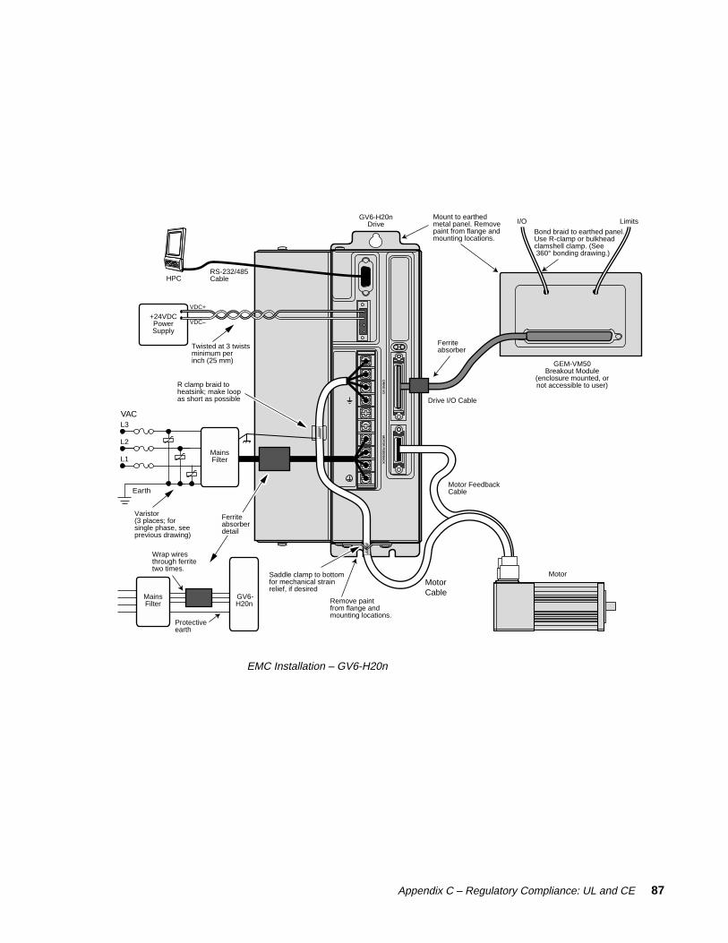
Appendix C – Regulatory Compliance: UL and CE 87
DR
IVE
I/OM
OT
OR
FE
ED
BA
CK
Twisted at 3 twistsminimum per inch (25 mm)
R clamp braid to heatsink; make loop as short as possible
GEM-VM50Breakout Module
(enclosure mounted, ornot accessible to user)
RS-232/485Cable
Drive I/O Cable
Motor FeedbackCable
MotorCable
GV6-H20nDrive
HPC
Motor
VDC+
VDC–+24VDCPowerSupply
Varistor(3 places; for single phase, see previous drawing)
Earth
VAC
Saddle clamp to bottomfor mechanical strain relief, if desired
MainsFilter
MainsFilter
GV6- H20n
L1
L2
L3
Bond braid to earthed panel.Use R-clamp or bulkheadclamshell clamp. (See 360° bonding drawing.)
I/O Limits
Ferrite absorberdetail
Wrap wires through ferrite two times.
Protectiveearth
Ferrite absorber
Mount to earthedmetal panel. Remove paint from flange and mounting locations.
Remove paint from flange andmounting locations.
EMC Installation – GV6-H20n

88 Gemini GV6 Hardware Installation Guide
R clamp braid to drive; make loop as short as possible
GEM-VM50Breakout Module
(enclosure mounted, ornot accessible to user)
Drive I/O Cable
Motor FeedbackCable
MotorCable
GV6-H40nDrive
Motor
Varistor(3 places)
Earth
VAC
MainsFilterL1
L2
L3
Twisted at 3 twistsminimum per inch (25 mm)
VDC+
VDC–+24VDCPowerSupply
RS-232/485Cable
HPC
Bond braid to earthed panel.Use R-clamp or bulkheadclamshell clamp. (See 360° bonding drawing.)
I/O Limits
MainsFilter
GV6-H40n
Wrap wires through ferrite two times.
Protectiveearth
Mount to earthedmetal panel. Remove paint from flange and mounting locations.
Remove paint from flange andmounting locations.
Ferrite absorberdetail
Ferrite absorber
EMC Installation – GV6-H40n

Index 89
IndexSymbols
+24VDC keep alive power 34, 56+24VDC power input 3526 pin breakout module 7626 pin connector kit 76360° bonding 8550 pin breakout module 74
A
AC input voltage 16, 56AC power 16, 56accessories 12accuracy 56aligning resolver 40analog input 63analog monitor 62, 63autorun mode 53axis status 50
B
bonding 85brake 34breakout module 74, 76
C
cabinet mounting 84cable
specifications 74troubleshooting 52
CE 4, 57, 82CE Marking Directive 4CNTRL-P 60color code 75COM port 51communications 57configuration 24configuration status 50configure drive 18connector
Drive I/O 58, 64Motor Feedback 64RS-232/485 42
cUL 57, 82current foldback 73current limiter 72
D
descriptions 8digital outputs 60, 61dimensions 67download procedures 46drive configuration 18, 24drive dimensions 67Drive I/O connector 58drive settings 25
E
electromagnetic compatibility 82EMC 57, 82EMC installation 86enable input 59enclosure mounting 84encoder 65encoder outputs 61environmental specifications 57error log 49express setup 12
F
fault settings 25feedback 64feedback cable 15filters 30, 83firmware 46flying lead cable 75foldback 73fuses 16
G
GC-26 26 pin connector 76GC-50 50 pin connector 76GEM-VM50 74GFB-KIT 26 pin connector kit 76GPDM 37
H
Hall effects 66
I
I/Oconnector 58, 64pinouts 58settings 26
INDEB 60INLVL 60input voltage 56inputs 58inrush current 72
K
keep alive power 34, 56
L
lag filter 31lead filter 31LEDs 48load settings 25loop back test 52Low Voltage Directive 4LVD 4, 57, 82
M
mains fuses 82modem cable 74Motion Planner 24motor
brake 34cable 15connections 14feedback cable 15overtemperature 72parameter table 78requirements 78settings 24thermal switch 66
Motor Feedback connector 64mounting 85multiple drives 35

90 Gemini GV6 Hardware Installation Guide
N
naming system 9non-Compumotor motor 78notch filter 30null modem cable
troubleshooting 52wiring and color code 74
numbering system 9
O
operating system 46options 12output power 56outputs 58, 60, 61overtemperature limits 72overvoltage protection 73
P
panel mounting 85part numbering system 9pass through encoder mode 61performance 56Pocket Motion Planner 24position mode tuning 28Power Dissipation Module
(GPDM) 37protective circuits 72pseudo encoder mode 61
R
regeneration 36, 73regulatory agencies 82relay 34reset input 59resolver
aligning 40connections 65
RS-232 daisy chain 43, 52RS-232/485
connector 42troubleshooting 51
RS-485communications 45multi-drop 46
S
serial port 42sharing power bus 36ship kit 12short circuit protection 72software commands 49specifications 56standards 57system settings 25
T
TAS 49TASX 50TCS 50temperature 57temperature limits 72TERRLG 49thermal switch 66tuning
position mode 28
U
UL 57, 82undervoltage protection 73update procedures 46upload procedures 46user guides 10
V
V Bus± 36varistors 83VINref 59VM50 74
W
weight 57

RS
-232/485
DR
IVE
I/OM
OT
OR
FE
ED
BA
SERVO
U
V
W
VBUS+
VBUS
MO
TOR
WA
RN
ING
: Haz
ardo
us v
olta
ge m
ay e
xist
for
up t
o
MalePins
GV6GeminiServo
To configure all drive parameters, connect a PC or HPC to this port. Use Motion Planner or Pocket Motion Planner for drive configuration.
User supplies +24VDC for "keep alive" power to drive: 19.2 – 28.8 VDC 500 mA minimum
When drive is enabled, it holds relay closed.
Relay rating: 5A at 24VDC or 120VAC.
If drive is faulted or disabled, relay will open. (Typical use: control of motor brake.)
Motor Output Connections – see page 14
AC Input Connections– see page 16
RS-232/485 Connector – Configuration Port: see page 42 50 Pin DRIVE I/O Connector – see page 58
26 Pin MOTOR FEEDBACK Connector – see page 64
+24VDC/Relay Connector – see page 34
6 7 8 9
21 3 4 5
Rx Tx GndRS-232 Connections
21 3 4 5
6 7 8 9
Rx-(RD A)
Tx-(TD A)
GndRx+(RD B)
Tx+(TD B)
RS-485 Connections
+24V DC
24V RTN
RELAY COM
RELAY N.O.
U
V
W
Motor Cable
DRIVECompumotor CableColor Code:
Black #1
Black #2
Black #3
Grn/Yel
Gemini GV6Digital Servo Controller/Drive
Operating Temperature Still Air: 45°C (113°F) Moving Air: 50°C (122°F)Storage Temperature: -40°C – 85°C (-40°F – 185°F)Humidity: 0 – 95%, non-condensingShock: 15g, 11msec half sineVibration: 10 – 2000 Hz at 2g
Environmental Specifications – see page 57
Short Circuit Protection Inrush Current ProtectionDrive Overtemperature ProtectionMotor Overtemperature ProtectionUndervoltage Protection Overvoltage Protection Current FoldbackRegeneration Protection
Protective Circuits – see page 72
LED Color: Left Right Indicated State Off Yel InitializationRed (flash) Off Awaiting flash downloadRed (flash) Yel (flash) Programming flash memoryRed Grn Keep alive mode Grn Grn (flash) Incoming steps (variable rate)Grn Yel/Grn (flash) Autorun modeRed Off Drive not enabled Drive faultedGrn Off Drive ready
Yellow/GreenGreen/Red
LEDs – see page 48
Cos–
ReservedReserved
Ref 1–Ref 1+Hall CHall BHall A
Hall GroundHall +5V
Thermal SwitchThermal SwitchDigital GroundEncoder Z–Encoder Z+Encoder B–Encoder B+Encoder A–Encoder A+Encoder GroundEncoder GroundEncoder +5VEncoder +5V
13121110987654321
26
222120191817161514
Troubleshooting – see page 47
Commonly used status commands (binary status bits are numbered 1 to n, from left to right):
TERRLG Error log reports the last 10 error conditions (cleared with CERRLG).
TAS General report, including fault conditions.TASX Additional report of conditions not covered with
TAS.TCS If TASX bit #7 or bit #28 is set, you can identify
the cause with TCS. TINO Bit #6 indicates status of Enable input ("1" = OK
to enable drive).TIN Status of digital inputs, including end-of-travel
inputs.TOUT Status of digital outputs.
You must configure all motor parameters. Be sure to follow the drive configuration procedure (see Chapter 2 Installation).
Any fault condition causes the drive to shut down.
The drive can not be enabled (DRIVE1) unless the Enable input is grounded and the Reset input is not grounded.
Use one of three methods to reset the drive (all command settings are remembered after reset): Issue the RESET command. Momentarily close the Reset input. Cycle power to the drive.
Output GroundOutput 6Output 5
Output GroundOutput 4Output 3
Output GroundOutput 2
Output GroundOutput 1
Input GroundInput 8Input 7Input 6
Input GroundInput 5Input 4
CNTRL-P: 4 – 8Input Ground
Input 3
Input 2
CNTRL-P: 1 –
Analog GroundAnalog Input–Analog Input+Analog Output BAnalog Output ADigital GroundEncoder Out Z–Encoder Out Z+Encoder Out B–Encoder Out B+Encoder Out A–Encoder Out A+ReservedReservedReservedReservedReservedReservedDigital GroundDigital Ground+5VDC Output+5VDC OutputResetDigital GroundEnable
25242322212019181716151413121110987654321
25242322212019181716151413121110987654321
5049484746454443424140393837363534333231
29
2726
GV6-L3n at 120VAC
95 – 132VAC
GV6-U3n/6n/12nat 120/240VAC
VBUS–
L2/N
L195 – 264VAC
FusesN/C
N
L1
Fuses
GV6-H20n at 208/240VAC 1-phase
165 – 264VAC,1-phase
Fuses
L3
L2
L1
GV6-H20n/H40n at208/240VAC 3-phase
165VAC – 264VAC3-phase
L3
L2
L1
Fuses