ge ccus technologies - cmccmcghg.com/wp-content/uploads/2015/12/20151127-cmc-calgary-stall... ·...
TRANSCRIPT

Imagination at work
GE CCUS Technologies CMC CO2lloquium, Calgary November 27th, 2015
GE Proprietary Information
Development Driver

© 2015, General Electric Company and/or its affiliates. GE Proprietary Information. All rights reserved. Information contained in this document is indicative only. No representation or warranty is given or should be relied on that it is complete or correct or will apply to any particular project. This will depend on the technical and commercial circumstances. It is provided without liability and is subject to change without notice. No reproduction, use or disclosure to third parties, without prior written permission.
44 GtCO2
2035 450 ppm (+2°C)
37 GtCO2
Power generation : Largest contributor and easiest to address
Who is currently emitting CO2?
Global CO2 emissions (Gt per year)
30 GtCO2
Source: © OECD/IEA – World Energy Outlook 2012
22 GtCO2
Power generation
All other sectors
2010
Power generation
Industry
Transport Others
2035 BAU (6°C)
2035 Current
Policies (4°C) Source: data from © OECD/IEA – CO2 emissions
from fossil combustion 2012
CMC CO2lloquium | 27th Nov 2015 3
© 2015, General Electric Company and/or its affiliates. GE Proprietary Information. All rights reserved. Information contained in this document is indicative only. No representation or warranty is given or should be relied on that it is complete or correct or will apply to any particular project. This will depend on the technical and commercial circumstances. It is provided without liability and is subject to change without notice. No reproduction, use or disclosure to third parties, without prior written permission.
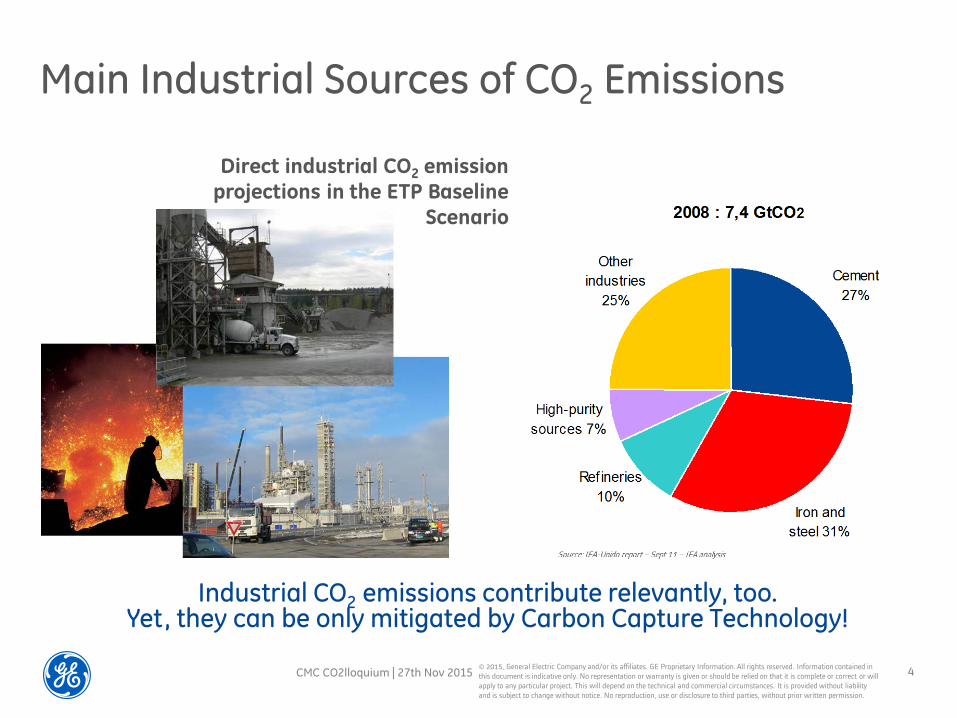
Main Industrial Sources of CO2 Emissions
Direct industrial CO2 emission projections in the ETP Baseline
Scenario
Industrial CO2 emissions contribute relevantly, too. Yet, they can be only mitigated by Carbon Capture Technology!
CMC CO2lloquium | 27th Nov 2015 4

Approach

© 2015, General Electric Company and/or its affiliates. GE Proprietary Information. All rights reserved. Information contained in this document is indicative only. No representation or warranty is given or should be relied on that it is complete or correct or will apply to any particular project. This will depend on the technical and commercial circumstances. It is provided without liability and is subject to change without notice. No reproduction, use or disclosure to third parties, without prior written permission.
Efficiency: Plant optimisation & retrofit
Wind, solar & geothermal
N° 1 nuclear*
& biomass
Emissions CO2 (Gt/y)
2005 Ref 2030 1000 ppm
+6oC
Stabilize emissions 550 ppm
+30C
Needed path
450ppm +20C max
Technology Mix
Efficiency
CCS
N° 1 hydro
* Conventional islands
Carbon Capture & Utilization or Storage
Clean Power strategy
CMC CO2lloquium | 27th Nov 2015 6

© 2015, General Electric Company and/or its affiliates. GE Proprietary Information. All rights reserved. Information contained in this document is indicative only. No representation or warranty is given or should be relied on that it is complete or correct or will apply to any particular project. This will depend on the technical and commercial circumstances. It is provided without liability and is subject to change without notice. No reproduction, use or disclosure to third parties, without prior written permission.
Underground permanent
Storage
Carbonates
Fuels
Urea
Food industry
Industrial flue gas with CO2:
• Power • Steel mill • Cement factory • Refinery • Methanol plant, • Ethanol plant • Fertilizer plant • etc
“Classic” CCS (Saline Aquifers or depleted Oil & Gas fields)
CCU Chemical usage
Current prospects in Fertilizer and carbonates
CO2-EOR CO2-EOR : high potential in USA
Carbon Capture & Utilization (CCU) A bridge towards large scale roll-out of CCUS
CO2 capture
unit
CMC CO2lloquium | 27th Nov 2015 7
© 2015, General Electric Company and/or its affiliates. GE Proprietary Information. All rights reserved. Information contained in this document is indicative only. No representation or warranty is given or should be relied on that it is complete or correct or will apply to any particular project. This will depend on the technical and commercial circumstances. It is provided without liability and is subject to change without notice. No reproduction, use or disclosure to third parties, without prior written permission.
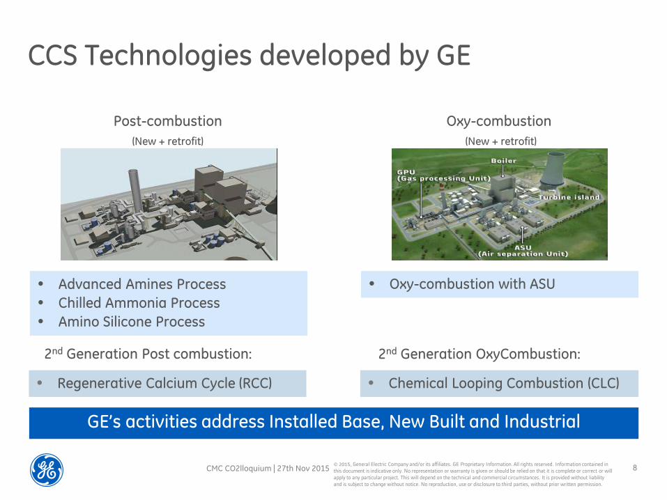
CCS Technologies developed by GE
GE’s activities address Installed Base, New Built and Industrial
Post-combustion Oxy-combustion (New + retrofit) (New + retrofit)
• Advanced Amines Process • Chilled Ammonia Process • Amino Silicone Process
• Oxy-combustion with ASU
• Regenerative Calcium Cycle (RCC) • Chemical Looping Combustion (CLC)
2nd Generation Post combustion: 2nd Generation OxyCombustion:
CMC CO2lloquium | 27th Nov 2015 8

Post Combustion

© 2015, General Electric Company and/or its affiliates. GE Proprietary Information. All rights reserved. Information contained in this document is indicative only. No representation or warranty is given or should be relied on that it is complete or correct or will apply to any particular project. This will depend on the technical and commercial circumstances. It is provided without liability and is subject to change without notice. No reproduction, use or disclosure to third parties, without prior written permission.
CAP- Chilled Ammonia Process
TECHNOLOGY PRINCIPLE • At low temperature, flue gas is contacted with an aqueous ammoniated
carbonate solution to absorb carbon dioxide
• Raising the temperatures reverses the reaction – releasing pressurized CO2
ADVANTAGES • Energy-efficient capture of CO2 . • High CO2 purity, high CO2 pressure. • Tolerant to oxygen and other flue gas
impurities like SOx. • Stable reagent (no degradation). • No emission of harmful trace contaminants. • Low-cost and globally available reagent. • Value by-product (fertilizer). • Variable Regenerator pressure: 7 to 21 bara
• Low CO2 compression power demand
CMC CO2lloquium | 27th Nov 2015 10

© 2015, General Electric Company and/or its affiliates. GE Proprietary Information. All rights reserved. Information contained in this document is indicative only. No representation or warranty is given or should be relied on that it is complete or correct or will apply to any particular project. This will depend on the technical and commercial circumstances. It is provided without liability and is subject to change without notice. No reproduction, use or disclosure to third parties, without prior written permission.
AAP - Advanced Amine Process
TECHNOLOGY PRINCIPLE • An amine based solvent reacts with the CO2 in the flue gas
• Raising the temperature reverses this reaction, the CO2 is released and the solvent recycled
ADVANTAGES • Proven in natural gas & syngas purification
• More efficient capture of CO2 and less
solvent degradation than MEA
• Higher tolerance against oxygen &
trace contaminants
MARKET INTRODUCTION • Ready for small-scale and CCU full
commercial offering
• Ready for large-scale demonstration projects
CMC CO2lloquium | 27th Nov 2015 11

© 2015, General Electric Company and/or its affiliates. GE Proprietary Information. All rights reserved. Information contained in this document is indicative only. No representation or warranty is given or should be relied on that it is complete or correct or will apply to any particular project. This will depend on the technical and commercial circumstances. It is provided without liability and is subject to change without notice. No reproduction, use or disclosure to third parties, without prior written permission.
RCC- Regenerative Calcium Cycle
ADVANTAGES • RCC increases the total
power production, adding capacity
• High potential for lower net cycle efficiency penalty
• Ideal fit to the cement industry (and good potential in other industries)
• Spent limestone can be reused
TECHNOLOGY PRINCIPLE • Lime reacts with the CO2 in the flue gas to form Limestone while producing heat
• Raising temperature reverses reaction, CO2 is released and sorbent recycled
• Indirect heat transfer boosts Plant efficiency and CO2 quality
CMC CO2lloquium | 27th Nov 2015 12

Oxy Combustion

© 2015, General Electric Company and/or its affiliates. GE Proprietary Information. All rights reserved. Information contained in this document is indicative only. No representation or warranty is given or should be relied on that it is complete or correct or will apply to any particular project. This will depend on the technical and commercial circumstances. It is provided without liability and is subject to change without notice. No reproduction, use or disclosure to third parties, without prior written permission.
DCC Direct Contact Cooler
GPU Gas Processing Unit
FGD Desulfurization
ESP/FF Dust Elimination
ASU Air Separation Unit
Oxy-Combustion Process
TECHNOLOGY PRINCIPLE • Fuel is burned in a mixture of Oxygen and re-circulated flue-gas.
• Due to absence of Nitrogen, flue gas is enriched in CO2 and H2O
• After H2O condensing and purification, CO2 is compressed and send to storage
ADVANTAGES • Reliability
• Adaptable to all boiler types and fuels
• Rapid scale-up to >1,000 MWel range
• Retrofit in Oxy can be addressed
• Higher efficiency with supercritical/ultra-supercritical cycles
CMC CO2lloquium | 27th Nov 2015 14

© 2015, General Electric Company and/or its affiliates. GE Proprietary Information. All rights reserved. Information contained in this document is indicative only. No representation or warranty is given or should be relied on that it is complete or correct or will apply to any particular project. This will depend on the technical and commercial circumstances. It is provided without liability and is subject to change without notice. No reproduction, use or disclosure to third parties, without prior written permission.
CLC - Chemical Looping Combustion TECHNOLOGY PRINCIPLE • Oxygen Carrier picks up oxygen in Air Reactor and brings oxygen to the
Fuel Reactor for Combustion • Oxygen Carrier regenerated in Air Reactor
ADVANTAGES • Eliminates need for energy
intensive ASU • Heat generated to produce
steam for electricity • Concentrated CO2 leaves Fuel
Reactor for utilization and storage (CCUS) 6 90% Capture
CMC CO2lloquium | 27th Nov 2015 15

Summary

© 2015, General Electric Company and/or its affiliates. GE Proprietary Information. All rights reserved. Information contained in this document is indicative only. No representation or warranty is given or should be relied on that it is complete or correct or will apply to any particular project. This will depend on the technical and commercial circumstances. It is provided without liability and is subject to change without notice. No reproduction, use or disclosure to third parties, without prior written permission.
We are a recognized leader in CCUS Technologies for a promising market after 2020
CCUS development conclusion
– CCUS is the sole solution to address CO2 emissions from industries
– Recognized leader on CCUS technology based on last 10 years development including 13 pilots and validation plants
– Proven and robust technologies capable to serve power and industry
– 2nd gen technologies promise to be breakthrough technologies in terms of energy penalty and CoE
– R&D focused on closing technology gaps, supporting new large demo-plants and develop 2nd generation to maintain a leading role in CCUS Technologies
CMC CO2lloquium | 27th Nov 2015 17
