ge ballast products catalog - crescent electric supply …
TRANSCRIPT

FEATURING:ULTRA TM
ELECTRONICBALLASTS
TRANSFORMING THEPOWEROF
LIGHT™
GE BALLAST PRODUCTSCATALOG
GE
BA
LLA
ST
PRO
DUCTS
CATA
LO
G

For more information, visit www.gelighting.com
GE BALLAST PRODUCTS CATALOG
U L T R AELECTRONIC BALLAST
MAX™
FEATURING
Breakthrough technology that dramaticallyimproves efficiency, simplifies installationand delivers optimal lamp performance.
TABLE OF CONTENTS
Fluorescent Electromagnetic Ballasts
Product Overview . . . . . . . . . . . . . . . . . . . . . .2-1Application and Operation Information . . . . . . . .2-4Typical Specifications . . . . . . . . . . . . . . . . . . .2-7Lead Lengths . . . . . . . . . . . . . . . . . . . . . . . .2-8F40T12 . . . . . . . . . . . . . . . . . . . . . . . . . . . .2-9F40T10 . . . . . . . . . . . . . . . . . . . . . . . . . . .2-11T12 High Output . . . . . . . . . . . . . . . . . . . . .2-12T12 Very High Output . . . . . . . . . . . . . . . . . .2-14F96PG17 . . . . . . . . . . . . . . . . . . . . . . . . . .2-15F96T12 Very High Output . . . . . . . . . . . . . . .2-15T12 Slimline . . . . . . . . . . . . . . . . . . . . . . . .2-16Circline . . . . . . . . . . . . . . . . . . . . . . . . . . . .2-18Preheat and Trigger . . . . . . . . . . . . . . . . . . .2-19Dimming . . . . . . . . . . . . . . . . . . . . . . . . . . .2-21Export . . . . . . . . . . . . . . . . . . . . . . . . . . . .2-22Wiring Diagrams . . . . . . . . . . . . . . . . . . . . .2-23
Sign Illuminating Ballasts
Product Overview . . . . . . . . . . . . . . . . . . . . . .3-1Application and Operation Information . . . . . . . .3-2High Output Sign Ballasts . . . . . . . . . . . . . . . .3-3Lead Length & Ballast Footage . . . . . . . . . . . . .3-4Wiring Diagrams . . . . . . . . . . . . . . . . . . . . . .3-5
Compact Fluorescent Ballasts
Product Overview . . . . . . . . . . . . . . . . . . . . . .4-1Understanding Compact Fluorescent Technology .4-3Specifications . . . . . . . . . . . . . . . . . . . . . . . .4-4
Understanding Part Numbers . . . . . . . . . . . . .4-5Twin/Quad Lamps 5-13 Watts . . . . . . . . . . . . .4-6Twin/Quad/Multiple Lamps 13-26 Watts . . . . . .4-7Multiple Lamps 32-70 Watts . . . . . . . . . . . . .4-82D Lamps 10-38 Watts . . . . . . . . . . . . . . . . .4-9T5 Circular Lamps 22-40 Watts . . . . . . . . . .4-11T5 Long Twin Lamps 24-96 Watts . . . . . . . . .4-12Wiring Diagrams . . . . . . . . . . . . . . . . . . . . .4-15
High Intensity Discharge (HID) Ballasts
Product Overview . . . . . . . . . . . . . . . . . . . . . .5-1Application and Operation Information . . . . . . . .5-5Nomenclature . . . . . . . . . . . . . . . . . . . . . . .5-10Specifications . . . . . . . . . . . . . . . . . . . . . . .5-11Distributor Replacement Kits . . . . . . . . . . . . .5-12Core and Coil . . . . . . . . . . . . . . . . . . . . . . .5-14
Metal Halide . . . . . . . . . . . . . . . . . . . . . .5-14Pulse Start Metal Halide . . . . . . . . . . . . .5-19High Pressure Sodium . . . . . . . . . . . . . . .5-22Mercury . . . . . . . . . . . . . . . . . . . . . . . . .5-26
F-Can Ballasts . . . . . . . . . . . . . . . . . . . . . . .5-27HID Controls/Part Numbers & Accessories . . .5-29Ignitors . . . . . . . . . . . . . . . . . . . . . . . . . . .5-31Wiring Diagrams . . . . . . . . . . . . . . . . . . . . .5-32
Glossary
Warranty
Electronic Ballasts Featuring New UltraMax™ Technology
Product Overview . . . . . . . . . . . . . . . . . . . . . .1-1UltraMaxTM Electronic Ballasts Overview . . . . . . .1-2UltraMaxTM System Performance Matrix . . . . . .1-7UltraMaxTM Ordering Guide and System Wattage 1-8Additional Electronic Ballast Overview . . . . . . . .1-9 Safety . . . . . . . . . . . . . . . . . . . . . . . . . . . .1-11Performance . . . . . . . . . . . . . . . . . . . . . . . .1-12 Specifications . . . . . . . . . . . . . . . . . . . . . . .1-14Ballast Matrix . . . . . . . . . . . . . . . . . . . . . . .1-18F17T8 . . . . . . . . . . . . . . . . . . . . . . . . . . . .1-20F25T8 . . . . . . . . . . . . . . . . . . . . . . . . . . . .1-21F28T8 . . . . . . . . . . . . . . . . . . . . . . . . . . . .1-22F32T8 . . . . . . . . . . . . . . . . . . . . . . . . . . . .1-23F40T8 . . . . . . . . . . . . . . . . . . . . . . . . . . . .1-28 F96T8 Slimline . . . . . . . . . . . . . . . . . . . . . .1-29T8HO . . . . . . . . . . . . . . . . . . . . . . . . . . . . .1-30T5 . . . . . . . . . . . . . . . . . . . . . . . . . . . . . .1-31T10 . . . . . . . . . . . . . . . . . . . . . . . . . . . . . .1-32T12 Rapid Start . . . . . . . . . . . . . . . . . . . . . .1-33T12 Slimline . . . . . . . . . . . . . . . . . . . . . . . .1-36T12HO High Output . . . . . . . . . . . . . . . . . . .1-37Wiring Diagrams . . . . . . . . . . . . . . . . . . . . .1-38Dimming Product Overview . . . . . . . . . . . . . .1-40Dimming Application and Operating Information 1-41Dimming Specifications . . . . . . . . . . . . . . . . .1-42Dimming Controls Cross Reference . . . . . . . .1-43Dimming T8 . . . . . . . . . . . . . . . . . . . . . . . .1-44Dimming Wiring Diagrams . . . . . . . . . . . . . .1-46

ELECTRONICFLUORESCENT BALLASTS
GE offers electronic ballasts for a wide range of applications.
A COMPREHENSIVE RANGEOF SOLUTIONS... FROM THE NAME YOU TRUST
GE introduced the first fluorescent ballast more than60 years ago. Today we are providing high frequency electronic ballasts for almost every fluorescent application.
With our UltraMaxTM Ballasts, we are bringing you the future inballast performance.
GE revolutionizes lighting again with new, breakthrough technology.Our patented UltraMax™ electronic ballasts transform the power oflight into efficiency and savings from store shelves to the installationsite. It all starts with UltraMax's Multi-Voltage Control (MVC), whichautomatically adjusts to handle voltage from 120V through 277V.That cuts the ballast models you need to stock from 40 down to 13,which can dramatically reduce inventory carrying costs. UltraMax™
ballasts have ArcGuard Protection, too, with a UL Type CC Anti-ArcRating. Plus, they’re ultra lamp friendly, with an industry low LampCurrent Crest Factor of 1.4 for optimal lamp performance. And thesmall, low-profile design of the UltraMax™ ballasts makes retrofitseffortless at the job site.
For more information, visit www.gelighting.com 1-1
PROD
UCT
OVER
VIEW

The choice for High light output. With a ballast factor of 1.15,UltraMaxTM H delivers the mostlumens for maximum light or when you want more savings using fewer lamps. This is the first high-efficiency high-light output line for 2, 3 and 4 T8 lamps.
The Normal light option balances efficiencyand illumination. The most-used type of ballast, the N line saves energy withoutsacrificing lumens. A ballast factor of .87meets most application needs. For 1, 2, 3,and 4 T8 lamps in 2', 3', 4', and 8'lengths.
The Low watt option for Max energy savings.With a ballast factor of .77, the L line is the most energy efficient choice.It provides adequate illumination for most applications. For 1, 2, 3, and 4 T8 lamps in 2’, 3’, and 4’ lengths.
U L T R AELECTRONIC BALLAST
MAXU L T R AELECTRONIC BALLAST
MAX
ULTR
AMAX
TM
ELEC
TRON
IC
BALL
ASTS
ULTR
AMAX
TM
ELEC
TRON
IC
BALL
ASTS
transforming the power of light™1-2
GE revolutionizes lighting again withnew, breakthrough technology.
In the GE labs, our engineers have developeda new breed of ballasts to make lighting systemsthat save more energy, are more adaptable, anddeliver optimal lamp performance. The innovative,patented technology in our new UltraMaxTM elec-tronic ballasts exceeds expectations, and is likenothing else available.
Multi-Voltage technology means a singleUltraMaxTM model handles voltage from120 through 277.
UltraMaxTM Ballasts can virtually “read’’ theincoming voltage and adapt automatically to anyvoltage from 108V to 305V. The benefits of Multi-Voltage Control (MVC) are obvious:
• Fewer models handle more jobs, eliminatinginventory hassles.
• MVC simplifies installation and eliminatesguesswork at the job site.
• MVC compensates for incoming voltage fluctuations or variations from unreliablepower.
UltraMaxTM is the only full line of T8 ballasts with a UL Type CC Anti-ArcRating.
UL Type CC Rating is a stringent designationof protection against arcing in electrical devices.GE’s Arc-Guard design eliminates the damagingeffects arcing can have on lamps, ballasts andsockets.
High efficiency delivers up to 40% energy savings.
Ballasts are the new frontier of energy efficien-cy. Systems combining UltraMaxTM electronic bal-lasts and T8/WM lamps can deliver up to 40%energy savings over standard electromagneticallyballasted T12 systems. Since energy costs are typi-cally 80% of the overall cost of light, a more effi-cient system can pay for itself in a very short timeand provide an excellent return on investment.
UltraMaxTM is ultra lamp friendly.With an industry low lamp current crest factor
(LCCF) of 1.4, UltraMaxTM ensures optimal lampoperation and maximum lamp life, which can saveon lamp and maintenance costs.
Active Current Regulation (ACR) technology is a patented advantage.
UltraMax’s patented ACR modular designmeans individual inverter modules regulate theoutput current to each lamp. So, unlike conven-tional ballasts, if one lamp fails, the remaininglamps are not forced to operate at a higher cur-rent. This ensures optimal lamp performance.
Anti-Striation Control for better lightquality, with no striations.
UltraMaxTM is the only line of T8 ballasts withAnti-Striation Control. This advanced technologyeliminates the maintenance issues caused by stri-ating lamps, often referred to as spiraling orswirling. This provides a flicker- and worry-freeenvironment.
Fully parallel independent lamp operation makes system easier to maintain.
If one lamp fails, all the others in the systemstay lit. That means system maintenance is easierto manage.
UltraMaxTM is ultra-cool.UltraMax’s high efficiency design results in
ultra-cool operation that can provide additional AC energy savings, especially during peak demandperiods.
A big idea in a small package.The UltraMaxTM housing is smaller, lower-pro-
file and lightweight. That can be a big help inretrofits. It also means future fixture designs canbe more compact and streamlined.
Every unit is tested and proven beforeit’s shipped.
GE does 100% burn-in on every UltraMaxTM
ballast using our extreme open/short test, whichsimulates undesirable and harsh-use situations, soyou are assured of a system you can rely on rightout of the box.
GE Six Sigma quality backed by a full 5-year warranty.
UltraMaxTM is designed by GE’s expert engi-neers and custom-manufactured to our exactingSix Sigma specifications, all backed by a full 5-yearwarranty.
COMPARE THE ENERGY USEOF A THREE LAMP FIXTURE
1 STANDARD T12/WM SYSTEM
2 STANDARD ELECTRONICT8 SYSTEM
3 ULTRAMAXTM L SYSTEM WITH GE T8 WATT-MISER
117watts
87watts
68watts
1 2 3
A FULL FAMILY OF HIGHEFFICIENCY MULTI-VOLTAGEBALLASTS FOR ALL T8APPLICATIONS.
U L T R AELECTRONIC BALLAST
MAX
U L T R AELECTRONIC BALLAST
MAX
U L T R AELECTRONIC BALLAST
MAX
Applications:
Safety• No PCBs• UL Listed
- Class P, Type 1- Type CC- Type HL (Hazardous
Location)
Application Information• Minimum Starting
Temperature: 0°F, -18°C• Maximum Ambient
Temperature: 105°F, 40°C• Sound Rated A• Remote Mounting:
18' maximum lead length, 18AWG
• High Frequency LampOperation: Above 60 kHz
Physical Parameters (Except for the 4H model) Length: 9.50 in.Width: 1.70 in.Height: 1.2 in.Weight: 1.4 lbs.
OfficesRetailSchools Universities
PlantsHotelsWarehousesHospitals
See foryourself
how different UltraMaxTM
ballasts perform.
BALL
AST
FACT
OR
*SY
STEM
LUM
ENS
(285
0 Lu
men
s/La
mp)
*IN
PUT
WAT
TS
LUM
ENS
PER
WAT
T
* For a 2-Lamp F32T8 System at 277V
.77 4389 48 91
.87 4959 53 94
1.15 6555 73 90
L
N
H
For more information, visit www.gelighting.com 1-3
L
N
H
UltraMax™ electronic ballasts have 5% more energy efficiency than standard electronic ballasts. When combined with GE T8 Watt-Miser® lamps, it means up to 40% in energy savings.

U L T R AELECTRONIC BALLAST
MAXU L T R AELECTRONIC BALLAST
MAX
transforming the power of light™1-4
A SMALLER, LOWER PROFILE DESIGNIS A BIG IDEA FOR EFFICIENT INSTALLATION.
PHYSICALDIMENSIONSFor Ballast typesL, N and H (except 4H)
OVERALLDIMENSIONS
A (length)8.375 in.(21.273 cm)
B (width)1.25 in.(3.175 cm)
C (height)1.125 in.(2.858 cm)
MOUNTINGDIMENSIONS
D (length)8.875 in.(22.54 cm)
E (width)1.4375 in.(3.651 cm)
WEIGHTRANGE
1.00 to 1.50 lbs.(0.454 to 0.6804 kg.)
For more information, visit www.gelighting.com 1-5
ULTR
AMAX
TM
ELEC
TRON
IC
BALL
ASTS
It’s easy to see how smaller, lower-profileUltraMaxTM ballasts make even the toughestretrofits into easy fits.
B
D
E
A
C
TRANSFORMING THEPOWEROF
LIGHT™
NEW
WHENYOU WANT LIGHTING
DONE RIGHT,START WITH GE.
Up to 40% inenergy savings
One patented GEballast handles120V through277V
13 models canreplace more than40 conventionalelectronic ballasts

U L T R AELECTRONIC BALLAST
MAXU L T R AELECTRONIC BALLAST
MAX
ULTR
AMAX
TM
ELEC
TRON
IC
BALL
ASTS
ULTR
AMAX
TM
ELEC
TRON
IC
BALL
ASTS
transforming the power of light™1-6 1-7For more information, visit www.gelighting.com
CHOOSING THE RIGHT BALLAST IS SIMPLE.The easy-to-understand model numbering system helps you choose and install the right model.Instructions and wiring diagrams on each ballast label help assure a correct installation the first time.
TOTAL PERFORMANCE SYSTEM™ WARRANTY
Here are the facts behind the promise.It starts with precision manufacturing.
GE UltraMaxTM Electronic Ballasts are custom-manufactured to our exacting specifications. We work to assure you thereliability and quality you expect from GE.Manufacturing processes include rigorous testing andquality control. Quality standards are further assuranceof trouble-free performance.
• 100% burn-in of units to assure reliability.• GE’s extreme open/short Test which tests units’
ability to withstand severe current conditions.• Careful component selection and extensive testing
of elements prior to final approval.• Critical component placement and extensive testing
of elements prior to final approval.• Extensive lamp/ballast system testing which ensure
optimal operating performance and compatibility.• Comprehensive testing under adverse field and
accelerated life conditions to prevent failure in the field.
• Commitment to Six Sigma standards for world-class product and service excellence.
• Power line voltage spike protection that passes the IEEE surge test (where a 6000V pulse is applied to input leads). Compliance with all appropriate regulatory standards.
• Contact your GE representitive for specific warranty details.
TRANSFORMING
THEPOWEROF
LIGHT™
UltraMaxTM Total Performance System™ Warranty
GE Lighting is pleased to provide the following warranty covering GE
T8 fluorescent lamps and GE UltraMaxTM electronic ballasts.
GE Lighting warrants that lamps and ballasts comply with their respective published specifications and
are free from defects in material, workmanship and title.
This warranty only applies when GE lamps are operated on GE UltraMaxTM electronic ballasts that
have been properly wired and installed; are operated within the electrical values shown on the ballast
label; used in lighting equipment designed and approved for the application; and environmental
conditions (temperature, humidity and air movement) are within the normal specified operating range of
the system.
If lamps in systems meeting the above requirements fail due to factors within the lamp during the
initial three (3) years or 10,500 hours of operation, whichever comes first, after the date of purchase,
GE Lighting agrees to furnish replacement lamps at no charge. This warranty applies to lamps which
are operated on a burning cycle of 10 hours/start or more.
If a GE UltraMaxTM electronic ballast fails due to factors within the ballast during the initial five (5)
years after the date of manufacture, GE Lighting, at its option, will at no charge either replace the
defective ballast including paying a labor allowance or refund the purchase price of the ballast.
GE Lighting reserves the right to examine failed lamps and/or ballasts to determine the cause of
failure and patterns of lamp usage. These lamp and ballast warranties do not apply to any abnormal
use or use in violation of any applicable standard, code or instructions for use in installations including
those contained in the National Electric Code (NEC), The Standards for Safety of Underwriters
Laboratory, Inc. (UL), Standards for the American National Standards Institute (ANSI) or, in Canada, the
Canadian Standards Association (CSA).
The foregoing shall constitute the exclusive remedy of the purchaser and the sole liability of GE
Lighting for lamp and ballast warranties. NO WARRANTY OF MERCHANTABILITY OR FITNESS FOR A
PARTICULAR PURPOSE IS MADE OR IS TO BE IMPLIED. In no event shall GE Lighting be liable for any
other cost of damages including lost profits, incidental, special or consequential damages.
Notes: Light refers to "mean" lumen output relative to highlighted T12 Electromagnetic E.S. (energy saving) ballast systems. RLPW is mean system Lumens/Watt relative to highlighted T12 Electromagnetic E.S. (energy saving) ballast systems.Watts shown at 277 Volts.
SYSTEM PERFORMANCE COMPARISON MATRIXCompare the overall performance of a GE UltraMaxTM system to conventional lamp and ballast systems.
2-Lamp System Performance 4' Fluorescent
Electromagnetic E.S. Rapid Start Low Power (L) Normal UltraMaxTM L UltraMaxTM N UltraMaxTM H
Watt-Miser T12 (CW) Watts: 74 Watts: 64 Not Available Not Available Not Available Not Available Not AvailableBF: 0.90 BF: 0.86 Light: 100% Light: 96% RLPW: 100% RLPW: 110%
F32T8 & F32T8/XL (SP) Watts: 69 Watts: 63 Watts: 51 Watts: 58 Watts: 48 Watts: 53 Watts: 73 BF: 0.88 BF: 0.88 BF: 0.78 BF: 0.88 BF: 0.77 BF: 0.87 BF: 1.15 Light: 116% Light: 116% Light: 103% Light: 116% Light: 102% Light: 115% Light: 152% RLPW: 125% RLPW: 137% RLPW: 149% RLPW: 148% RLPW: 157% RLPW: 160% RLPW: 154%
F32T8/WM ULTRA & XL (SP) Not Not Watts: 48 Watts: 54 Watts: 46 Watts: 52 Watts: 70 Recommended Recommended BF: 0.78 BF: 0.88 BF: 0.77 BF: 0.87 BF: 1.15
Light: 102% Light: 115% Light: 100% Light: 113% Light: 150% RLPW: 157% RLPW: 157% RLPW: 161% RLPW: 161% RLPW: 158%
3-Lamp System Performance 4' Fluorescent
Electromagnetic E.S. Rapid Start Low Power (L) Normal UltraMaxTM L UltraMaxTM N UltraMaxTM H
Watt-Miser T12 (CW) Watts: 117 Watts: 93 Not Available Not Available Not Available Not Available Not AvailableBF: 0.91 BF: 0.86 Light: 100% Light: 95% RLPW: 100% RLPW: 119%
F32T8 & F32T8/XL (SP) Watts: 105 Watts: 93 Watts: 77 Watts: 87 Watts: 72 Watts: 80 Watts: 109 BF: 0.88 BF: 0.88 BF: 0.78 BF: 0.88 BF: 0.77 BF: 0.87 BF: 1.15 Light: 115% Light: 115% Light: 102% Light: 115% Light: 101% Light: 114% Light: 150% RLPW: 128% RLPW: 145% RLPW: 155% RLPW: 155% RLPW: 163% RLPW: 166% RLPW: 161%
F32T8/WM ULTRA & XL (SP) Not Not Watts: 72 Watts: 81 Watts: 68 Watts: 77 Watts: 104 Recommended Recommended BF: 0.78 BF: 0.88 BF: 0.77 BF: 0.87 BF: 1.15
Light: 101% Light: 113% Light: 99% Light: 112% Light: 148% RLPW: 163% RLPW: 164% RLPW: 171% RLPW: 170% RLPW: 167%
4-Lamp System Performance4' Fluorescent
Electromagnetic E.S. Rapid Start Low Power (L) Normal UltraMaxTM L UltraMaxTM N UltraMaxTM H
Watt-Miser T12 (CW) Watts: 148 Watts: 128 Not Available Not Available Not Available Not Available Not AvailableBF: 0.90 BF: 0.86 Light: 100% Light: 96% RLPW: 100% RLPW: 110%
F32T8 & F32T8/XL (SP) Watts: 138 Watts: 120 Watts: 100 Watts: 114 Watts: 96 Watts: 107 TBD BF: 0.88 BF: 0.88 BF: 0.78 BF: 0.88 BF: 0.77 BF: 0.87 Light: 116% Light: 116% Light: 103% Light: 116% Light: 102% Light: 115% RLPW: 125% RLPW: 143% RLPW: 152% RLPW: 151% RLPW: 158% RLPW: 159%
F32T8/WM ULTRA & XL (SP) Not Not Watts: 95 Watts: 107 Watts: 91 Watts: 103 TBD Recommended Recommended BF: 0.78 BF: 0.88 BF: 0.77 BF: 0.87
Light: 102% Light: 115% Light: 100% Light: 113% RLPW: 158% RLPW: 159% RLPW: 163% RLPW: 163%
Lamps Electromagnetic Ballasts Electronic Ballasts
U L T R AELECTRONIC BALLASTMAX
The right ballast. The right performance. The right light.
1 = Maximum number of lamps supported by this ballast. 32 = Lamp watts (primary lamp)
N = Normal ballast (ballast factor of .87)

U L T R AELECTRONIC BALLAST
MAX
1-9For more information, visit www.gelighting.com
ULTR
AMAX
TM
ELEC
TRON
IC
BALL
ASTS
transforming the power of light™1-8
ORDERING GUIDE AND SYSTEM WATTAGE There’s a combination of GE UltraMax™ ballasts and T8 lamps that can make virtuallyany lighting system perform better. The chart below lets you see for yourself.
High
Norm
alLo
wPo
wer
# Lam
ps
Star
ting
Insta
nt St
art
Norm
al
† Denotes standard laboratory non-fixture open bench testing. ∆ In fixture watts represent typical field operating conditions with ballast and lamps in fixture/luminaire.
Open fixture denotes non-lensed fixture/luminaire. Enclosed fixture denotes lensed fixture/luminaire.
Units
Units
GE UltraMax Ballasts F32T8 Input Watts F32T8/WM Input Watts F28T8/WM Input WattsProduct Description Input Input In Fixture∆ Input In Fixture∆ Input Input Fixture∆ PerCode Voltage Watts† Open Enclosed Watts† Open Enclosed Watts† Open Enclosed Case
1 49706 GE-132-MAX-L/Ultra Multi-Volt 120 25 24 24 24 23 23 22 TBD TBD 10277 25 24 24 24 23 23 22 TBD TBD
2 49707 GE-232-MAX-L/Ultra Multi-Volt 120 48 48 47 46 46 45 44 TBD TBD 10277 48 48 47 46 46 45 44 TBD TBD
3 49708 GE-332-MAX-L/Ultra Multi-Volt 120 73 72 71 69 68 67 65 TBD TBD 10277 72 71 70 68 67 66 65 TBD TBD
4 49709 GE-432-MAX-L/Ultra Multi-Volt 120 97 95 93 92 90 88 87 TBD TBD 10277 96 93 92 91 89 87 86 TBD TBD
1 49771 GE-132-MAX-N/Ultra Multi-Volt 120 28 28 27 27 26 26 25 TBD TBD 10277 28 28 27 27 26 26 25 TBD TBD
2 49772 GE-232-MAX-N/Ultra Multi-Volt 120 54 54 53 53 52 51 49 TBD TBD 10277 53 53 52 52 51 50 48 TBD TBD
3 49773 GE-332-MAX-N/Ultra Multi-Volt 120 82 80 78 78 77 74 72 TBD TBD 10277 80 78 77 77 75 73 71 TBD TBD
4 49774 GE-432-MAX-N/Ultra Multi-Volt 120 109 105 103 105 101 98 98 TBD TBD 10277 107 103 101 103 99 97 96 TBD TBD
2 49775 GE-232-MAX-H/Ultra Multi-Volt 120 74 71 69 71 69 67 66 TBD TBD 10277 73 70 68 70 68 66 65 TBD TBD
3 49776 GE-332-MAX-H/Ultra Multi-Volt 120 111 105 102 106 102 97 97 TBD TBD 10277 109 103 100 104 100 96 96 TBD TBD
4 49777 GE-432-MAX-H/Ultra Multi-Volt 120 151 TBD TBD 145 TBD TBD 133 TBD TBD 10277 147 TBD TBD 141 TBD TBD 131 TBD TBD
GE UltraMax Ballasts F96T8 Input Watts F96T8/WM Input Watts Product Description Input Input In Fixture∆ Input In Fixture∆ PerCode Voltage Watts† Open Enclosed Watts† Open Enclosed Case
1 49766 GE-159-MAX-N/Ultra Multi-Volt 120 56 TBD TBD 54 TBD TBD 10277 55 TBD TBD 53 TBD TBD
2 49767 GE-259-MAX-N/Ultra Multi-Volt 120 112 TBD TBD 107 TBD TBD 10277 110 TBD TBD 105 TBD TBD
PRODUCT OVERVIEW
AccuStart® and Universal Voltage LowProfile High Performance (HP-A & HP-B)
AccuStart® ballasts are ideal for frequentlyswitched applications or as a rapid start alternative.They incorporate patented programmed rapid starttechnology to properly heat the lamp filaments,which yields an increase in lamp life up to 50%. The1-4 lamp models offer universal input voltage.
Our low profile High Performance ballasts with THD <10% offer the convenience of universal inputvoltage (108-305 Volts) as a standard feature.Universal input is "installer-friendly" – ensuring thatyou have the right voltage ballast every time. Our lowprofile models also feature a package and cross-sec-tion that can offer greater flexibility in fixture design(1.0" height x 1.5" width). Since the mounting andwiring footprints are the same as a standard ballast,our low profile HP models will easily retrofit into anyT12 or T8 fixture.
Low Profile Reduced Harmonic (RH-A)Our low profile RH ballasts are over 45%
smaller and 30% lighter. They feature a space-sav-ing package (1.18" height x 1.7" width) and crosssection for greater flexibility in fixture design. The1-4 lamp model features parallel lamp operation,with standard mounting footprint and wiring forease of replacement. They offer high efficiencyperformance with THD <20%.
Low profile RH ballasts. AccuStart® ballasts for frequentlyswitched applications.
Flexible fixture design options forT5 lamps.
PROD
UCT
OVER
VIEW

transforming the power of light™1-10
ELECTRONICFLUORESCENT BALLASTS
1-11For more information, visit www.gelighting.com
ELECTRONICFLUORESCENT BALLASTS
PROD
UCT
OVER
VIEW
T5 systems are gaining greater popularity forhigh-end architectural applications. GE provides awide range of T5 solutions, from 14 to 54 watts.Our T5 ballasts operate multiple (1 or 2) F35T5,F28T5, F21T5 and F14T5 lamps. Additionally, ourT5HO ballasts operate multiple (1 or 2) F54T5HO,F39T5HO and F24T5HO lamps. Moreover, theymake your life easier with standard features thatinclude universal input voltage (108-305 Volts),programmed rapid start technology for longer lamplife and end of lamp life shutdown circuit withauto-reset.
T5 Standard OutputOur standard output ballasts for T5 applica-
tions support multiple lamp operation (including14, 21, 28, and 35 watts). They're ideal for indi-rect pendant mount, surface mount, cove, under-cabinet or task lighting. With a small cross section(1.0"height x 1.18"width), our T5 models giveyou more options for slim fixture design. Standardfeatures include universal input voltage, end-of-lamp-life shutdown circuit and programmed rapidstart technology.
T5 High OutputHigh output T5 ballasts from GE support 24-,
39- and 54-watt lamps and they offer the samestandard features and compact dimensions as our T5standard output. They're also well-suited to applica-tions where space is at a premium, including slimpendant mounted fixtures, cove and task lighting.
T5 BALLASTS FOR INDIRECT, HIGH-ENDARCHITECTURAL APPLICATIONS
NEC & UL RequirementsBallast installation presents the possibility of
exposure to potentially hazardous voltages andshould be performed only by qualified personnel.All installation, inspection, and maintenance shouldbe performed only with power to the fixture turnedoff. Additionally, all fixtures and ballasts must beinstalled and operated in compliance with theNational Electrical Code, Underwriters LaboratoriesInc. (UL) requirements, and all local applicablecodes and regulations.
PolarityPolarity refers to the proper connection of bal-
last lead wires to line wires. To aid you in making acorrect installation, GE ballast leads are color-codedfor easy identification. The WHITE ballast lead is tobe connected to the neutral (grounded) and theBLACK (or black with white tracer) lead always tothe phase (“hot”) line wire. Systems where neitherof the line wires are at ground potential requirespecially designed ballasts. A change in polaritymay result in the voltage from the lead to theground exceeding UL-specified limits. In some typesof ballasts, a change in polarity may decrease volt-age from the lead to the ground, thereby impedingthe starting dependability of the ballast.
GroundingBallast cases and fixtures must always be
grounded. The ballast case may be grounded to thefixture or otherwise grounded. It could be haz-ardous to make contact with an ungrounded fix-ture or ballast when in operation. Neglecting toproperly ground the ballast and fixture combinationmay also result in failure of certain lamps to start orfor unacceptable levels of electromagnetic noise tobe conducted onto the power lines.
Operating Line Voltage LimitsTo receive the full benefits of rated lamp output
and to prolong ballast life, it is essential that volt-age supplied to an installation be maintained with-in limits prescribed for each circuit. These limits arelisted in the next column.
Subjecting a ballast to excessive voltage for anextended period results in the deterioration of theinsulation. This insulation breakdown will causeearly ballast failure.
Low voltage has no damaging effect on theballast. However, lamps may not start reliably, andearly lamp failure could result.
Internal Ballast ProtectionClass P Classification—Since January 1, 1984,
the National Electrical Code requires that “whereFluorescent fixtures are installed indoors, the ballastshall have thermal protection integral within theballast except for simple reactance ballasts.” Thisruling applies to replacement ballasts as well as tothose contained within new fixtures.
In compliance with the National Electrical Code,UL has established a Class P ballast classification forfluorescent light fixtures. A Class P ballast mustemploy internal thermal protection limiting its oper-ating temperature.
GE UL-approved Class P ballasts comply withthe National Electrical Code requirement and areequipped with an automatic resetting thermalprotector, built-in and adjacent to the transformercoils. The resetting thermal protector functions asa thermostat, which will open and temporarilydeactivate the ballast when it exceeds the permis-sible temperature. It will reset when the ballastcools to a safe operating temperature. The ballastwill continue to cycle until the cause of overheat-ing is eliminated. If the ballast is defective, it mustbe replaced. If the cause is external, a Class P bal-last will resume normal operation after abnormal conditions are eliminated.
VOLTAGE RANGE
Nominal Voltage120220277347
120-277 (UNV)
Minimum108198249312108
Maximum132242305382305
SAFETY
APPL
ICAT
ION
AN
D OP
ERAT
ING
INFO
RMAT
ION

APPL
ICAT
ION
AN
D OP
ERAT
ING
INFO
RMAT
ION
1-13For more information, visit www.gelighting.com
ELECTRONICFLUORESCENT BALLASTS
transforming the power of light™1-12
ELECTRONICFLUORESCENT BALLASTS
APPL
ICAT
ION
AN
D OP
ERAT
ING
INFO
RMAT
ION
Dimming Ballasts - Ballastar® dimming ballastsfrom GE are controlled by using 10-0vDC. Careshould be taken to ensure that the line voltage(AC) wires are not connected to the low voltageDC wires. Ballastar® electronic dimming ballastshave protection (safety) circuitry that will sense theerror so as not to harm the installer or the ballast.Dimming ballasts manufactured after May 1999have the protection circuit. Dimming ballasts manu-factured before this date do not have low voltagecircuit protection.
Fusing - Class P ballasts do not require fusing.Fusing can be used when a single circuit has alarge number of fixtures/ballasts.
Grounding - ANSI C82.1 recommends all fixturesand ballasts be grounded. GE requires all electronicballasts be grounded.
Thermal Protection - All GE electronic ballastsmeet UL 935 Standard for thermal protection.These ballasts are designated Class P. A Class Pballast will disconnect the ballast from inputpower in the event of internal over-temperature.
SAFETY PERFORMANCE
Lamp ConnectionsFluorescent ballasts are designed to generate
voltages in excess of 300 Volts. It is imperativethat proper connection to quality sockets beassured in accordance with wiring diagrams oneach page of the catalog and on product labels.Some applications may not require the use of allof the ballast output leads. If any leads are not tobe connected, each should be individually cappedand insulated to at least 600 Volts.
Application VersatilityMany GE models are designed to allow for
applications with different types or quantities oflamps. Lamp applications not listed on label cannotbe warranted.
Audible Noise (Sound)Electrical equipment, including most
fluorescent lamp ballasts, produces some noise.Care must be taken to select a ballast with theproper sound rating for a particular lighting installation. Secure mounting can reduce thepotential for audible noise. Typically, electronic ballasts operate up to 75% quieter than electromagnetic ballasts for fluorescent lamps.
Remote MountingExcessive hot or cold temperatures, audible
noise requirements, or a desire to operate lampsin more than one fixture with the same ballast(master/slave), may make it desirable to mountthe ballast remotely. Care must be taken to allowfor ballast heat dissipation and proper grounding.
In any application, the wire used to extendleads must be at least as large as the wire sup-plied on the ballast (18 AWG) with an insulationrating of 1000 VAC at 90°C.
Lead lengths in excess of those noted, causeloading effects that can dramatically impact bal-last performance and void the warranty. GE T8instant start and programmed (rapid) start elec-tronic ballasts can be mounted remotely, from thelamp sockets, up to 18 feet. GE T8 rapid startelectronic ballasts can be mounted remotely, fromthe lamp sockets, up to 12 feet.
• Incorrect wiring• Poor heat dissipation due to surrounding insu-
lation• Sealed (Vapor Tight) Fixtures - Unusual heat
build-up due to lack of ventilation in fixturesmay cause thermal (on/off) cycling of certainballasts. Consult GE for specific recommendations.
Recommendations:• Selection of a proper ballast to match the
requirements of the lamp, fixture, voltageand installation
• Mounting of ballast within the fixture with asmuch surface contact as possible betweenthe ballast and metal portions of thefixture.Secure mounting will aid in proper heatdissipation and can minimize the potential forballast hum.
• The use of heat-conducting dissipators (radia-tors), if necessary, which increases surface con-tact between the ballast and fixture.
• If necessary, locate the ballast in a remote, cool-er area outside the fixture.
• Consult GE for remote mounting recommen-dations.
Starting Method LegendIS=Instant StartPRS=Programmed Rapid StartRS=Rapid StartPAR-IS=Parallel Instant StartPAR-PRS=Parallel Programmed Rapid StartPAR-RS=Parallel Rapid StartSER-RS=Series Rapid Start
Lamp Starting DependabilityFluorescent lamps are inherently more difficult
to start at low temperatures. All ballasts have limi-tations as to their ability to start lamps at lowambient temperatures. In this catalog, the lowstarting point for each lamp/ballast combinationappears in the column marked “Minimum StartingTemperature.”
Four lamp instant start ballasts can operate at aminimum starting temperature down to -18°C (0°F) under the following conditions:
1. Lead lengths to the lamps are thosesupplied, by GE, with the ballast or shorter.
2. The distance from the lamp to the groundplane is no greater than 3/4".
3. The line voltage supplied to the ballast is noless than rated nominal.
4. The ballast or lamps are not remotelymounted.
5. The lamps have been burned in per lampmanufacturer requirements (typically 100hours).
Contact GE for lamp operating characteristics andrequirments below 15°C (50°F).
Light OutputOptimum light output from fluorescent lamps
is achieved when the lamp wall is at 100-110°F.Any substantial excursion (either colder or warmer)will result in a reduction in light output.
Ballast LifeA fluorescent lamp ballast, like any other elec-
trical device, generates heat during its normaloperation. Ballast temperatures should be kept aslow as possible. Maximum dissipation of heatthrough fixture design and proper ballast installa-tion will help. Although excessive temperaturemay not cause the ballast to fail immediately, itcan shorten ballast life. To assure maximum life,the ballast case temperature should not exceed75°C, in a maximum ambient (fixture cavity) of40°C.
Causes of ballast overheating:• Incorrect line voltage or frequency• Incorrect size, type or number of lamps
PERFORMANCE, continued

TYPI
CAL
SPEC
IFIC
ATIO
NS
TYPI
CAL
SPEC
IFIC
ATIO
NS
transforming the power of light™1-14 1-15For more information, visit www.gelighting.com
ELECTRONICFLUORESCENT BALLASTS
ELECTRONICFLUORESCENT BALLASTS
TYPICAL SPECIFICATIONS FOR INSTANT STARTBALLASTS FOR:
• RH (Reduced Harmonics)• L (Low Wattage)• RHH (Reduced Harmonics High Light)
TYPICAL SPECIFICATIONS FOR INSTANT START BALLASTS FOR:
Universal Voltage Performance• HP (High Performance)
1. Ballasts (1-4 lamp) shall operate as a Parallel Circuit, allowing remaining lamp(s) to maintain full light output if one or more lamps fail.
2. Ballasts shall operate from 60 Hz input source of 120, 277 Volts, and sustained variations of ±10% (Voltage & Frequency) with no damage to the ballasts.
3. Ballasts shall be a high frequency electronic type,and operate lamps at a frequency above 20 kHz.
4. Lamp Current Crest Factor (ratio of peak to RMS current) shall be 1.7 or less in accordance with lamp manufacturer recommendation and ANSI C82.11-1993.
5. Ballasts shall tolerate operation in ambient temperatures up to 105°F (40°C) without damage.
6. Ballasts shall comply with FCC Part 18 Non-Consumer Equipment for EMI (power line conducted) and RFI (Radiated).
7. Ballasts shall provide transient immunity as recommended by ANSI C62.41-1991, Location A2.
8. Ballasts shall operate lamps with no visible flicker (< 3% flicker index).
9. Ballasts shall tolerate sustained open circuit and short circuit output conditions without damage.
10. Ballasts shall be Underwriters Laboratory (UL 935) listed, Class P, Type 1 Outdoor, and CSA certified where applicable.
11. Ballast shall have a Ballast Factor greater than .85 per ANSI C82.11-1993. Ballast Factor for Low Power (L)models shall be greater than .77.
12. Input current Total Harmonic Distortion shall not exceed 20% for the primary lamp applications.
13. Ballasts shall have a Power Factor greater than .95 for primary lamp applications.
14. The ballasts do not contain any PCBs.15. The manufacturer shall provide written warranty
against defects in material or workmanship, including replacement, for five years from date of manufacture.
16. Ballast shall be manufactured in an ISO 9001 Certified Facility.
17. Ballasts shall provide instant starting sequence consistent with ANSI standard C82.11-1993.
18. GE model __________________ (or approved equal).
1. Ballasts (1-4 lamp) shall operate as a Parallel Circuit, allowing remaining lamp(s) to maintain full light output if one or more lamps fail.
2. Ballasts shall operate from 50/60 Hz input source of120 through 277 Volts, and sustained variations of ±10% (Voltage & Frequency) with no damage tothe ballasts.
3. Ballasts shall be a high frequency electronic type, and operate lamps at a frequency above 42 kHz to minimize interference with infrared control systems.
4. Lamp Current Crest Factor (ratio of peak to RMS current) shall be 1.7 or less in accordance with lampmanufacturer recommendation and ANSI C82.11-1993.
5. Ballasts shall tolerate operation in ambient tempera-tures up to 105°F (40°C) without damage.
6. Ballasts shall comply with FCC Part 18 Non-Consumer Equipment for EMI (power line conducted) and RFI (Radiated).
7. Ballasts shall provide transient immunity as recommended by ANSI C62.41-1991, Location A2.
8. Ballasts shall operate lamps with no visible flicker (<3% flicker index).
9. Ballasts shall tolerate sustained open circuit and short circuit output conditions without damage.
10. Ballasts shall be Underwriters Laboratory UL 935)listed, Class P, Type 1 Outdoor, and CSA certifiedwhere applicable.
11. Ballast shall have a Ballast Factor greater than .85per ANSI C82.11-1993.
12. Input current Total Harmonic Distortion shall not exceed 10% for the primary lamp.
13. Ballasts shall have a Power Factor greater than .98 for primary lamp.
14. The ballasts shall not have any PCBs.15. The manufacturer shall provide written warranty
against defects in material or workmanship,includ-ing replacement, for five years from date of manu-facture.
16. Manufacturer shall have been manufacturing elec-tronic ballasts for at least fifteen years.
17. Ballast shall be manufactured in an ISO 9001Certified Facility.
18. Ballasts shall provide instant starting sequence con-sistent with ANSI standard C82.11-1993.
19. Ballast shall be Bx32IUNVHP-B (x=1 or 2) orBx32IUNVHP-A (x=3 or 4) depending upon thequantity of lamps per fixture.
20. GE model ______________ (or approved equal).
TYPICAL SPECIFICATIONS FOR ULTRAMAXMULTI-VOLTAGE, INSTANT START, HIGHEFFICIENCY BALLASTS
Section I – Physical Characteristics1.1 The electronic ballast shall be physically
interchangeable with standard electromagnetic and standard electronic ballast.
1.2 The electronic ballast shall have a maximum height of 1.2 in. and maximum weight of 1.5 lbs. (except 4H).
1.3 The electronic ballast shall be furnished with integral leads, color-coded to ANSI C82.11.
Section II – Performance Requirements2.1 The electronic ballast shall operate throughout wide
range of input line voltage 120-277 Volts, with +/-10% variation tolerance 50/60 Hz for Multi Voltage Control /Universal Voltage.
2.2 Ballast shall be classified “hi-efficiency” and shall provide a minimum of 3 watts energy savings over comparable standard electronic ballasts.
2.3 The electronic ballast input current shall have Total Harmonic Distortion (THD) of less than 10% when used with the primary lamp at 120 Volts. It shall be less than 20% on other approved lamps.
2.4 The electronic ballast shall have a Power Factor greaterthan 98% when used with primary lamp at 120 Volts and greater than 95% at 277 Volts.
2.5 The electronic ballast shall be Sound Rated A.2.6 The electronic ballast output frequency to the lamps
shall be above 60 kHz to minimize interference with infrared control systems and eliminate visible flicker.
2.7 The electronic ballast shall meet ANSI C82.11 for Electronic Ballast Performance.
2.8 The electronic ballast shall withstand transients specified in ANSI C62.41, Location Category A3.
2.9 The electronic ballast shall be Instant Start with independent parallel lamp operation.
2.10 The electronic ballast shall have a Lamp Current Crest Factor of <1.5.
2.11 Lamps may be remote or tandem mounted up to a maximum of 18ft. overall lead length between ballastsand lamps.
2.12 Ballast shall have a minimum starting temperature of 0ºF for F32T8, F25T8 and F17T8.
Section III – Regulatory3.1 The electronic ballast shall meet the requirements
of the Federal Communications Commission rules and regulations, Title 47 CFR part 18, for Non- Consumer equipment.
3.2 The electronic ballast shall comply with all applicable state and federal efficiency standards.
3.3 The electronic ballast shall be Underwriters Laboratories (UL) Listed Class P & Type HL.
3.4 The electronic ballast shall provide UL Class CC, Closed Cabinet protection to prevent ignition of non-UL–controlled thermoplastic diffuser and overheating of bi-pin lampholders.
Section IV – Other4.1 The electronic ballast shall not contain
Polychlorinated Biphenyl (PCBs).4.2 The electronic ballast shall carry a five year warranty
form the date of manufacture. Warranty shall be valid for maximum case temperature of 70ºC.
4.3 The electronic ballast shall eliminate lamp striation (spiraling effect).
4.4 The electronic ballast shall be available in 1, 2, 3, & 4 lamp versions for F32T8 and 1 & 2 lamp versions for F96T8.
4.5 The F32T8 electronic ballast shall be available with Ballast Factor of .77 Low, .87 Normal, and 1.15 High Power.
4.6 The electronic ballast shall have constant Ballast Factor if one or more lamps fail.

TYPI
CAL
SPEC
IFIC
ATIO
NS
1-17For more information, visit www.gelighting.com
ELECTRONICFLUORESCENT BALLASTS
TYPI
CAL
SPEC
IFIC
ATIO
NS
transforming the power of light™1-16
ELECTRONICFLUORESCENT BALLASTS
1. Ballasts (1-4 lamp) shall operate as a Parallel Circuit, allowing remaining lamp(s) to maintain full light output if one or more lamps fail (except T12 High Output).
2. Ballasts shall operate from 50/60 Hz input source of 120, 277, and 347 Volts, and sustained variations of 10% (Voltage & Frequency) with no damage to the ballasts.
3. Ballasts shall be a high frequency electronic type, and operate lamps at a frequency above 20 kHz.
4. Lamp Current Crest Factor (ratio of peak to RMS current) shall be 1.7 or less in accordance with lamp manufacturer recommendation and ANSI C82.11-1993.
5. Ballasts shall tolerate operation in ambient temperatures up to 105°F (40°C) without damage. Ballasts shall comply with FCC Part 18 Non-Consumer Equipment for EMI (power line conducted) and RFI (Radiated).
6. Ballasts shall provide transient immunity as recommended by ANSI C62.41-1991, Location A2.
7. Ballasts shall operate lamps with no visible flicker (< 3% flicker index).
8. Ballasts shall tolerate sustained open circuit and short circuit output conditions without damage.
9. Ballasts shall be Underwriters Laboratory (UL 935) listed, Class P, Type 1 Outdoor, and CSA certified where applicable.
10. Ballast shall have a Ballast Factor greater than .85 per ANSI C82.11-1993. Ballast Factor for Low Power (L) models shall be greater than .77.
11. Input current Total Harmonic Distortion shall not exceed 10% for the primary lamp.
12. Ballasts shall have a Power Factor greater than .98 for primary lamp.
13. The ballasts do not contain any PCBs.14. The manufacturer shall provide written warranty
against defects in material or workmanship, including replacement, for five years from date of manufacture.
15. Ballast shall be manufactured in an ISO 9001 Certified Facility.
16. Ballasts shall provide instant starting sequence consistent with ANSI standard C82.11-1993.
17. GE model__________________(or approved equal).
1. Ballasts (1-4 lamp) shall operate as a Parallel Circuit, allowing remaining lamp(s) to maintain full light output if one or more lamps fail (except T12 High Output).
2. Ballasts shall operate from 60 Hz input source of 120, 277 Volts, and sustained variations of ±10% (Voltage & Frequency) with no damage to the ballasts.
3. Ballasts shall be a high frequency electronic type, and operate lamps at a frequency above 20 kHz.
4. Lamp Current Crest Factor (ratio of peak to RMS current) shall be 1.7 or less in accordance with lamp manufacturer recommendation and ANSI C82.11-1993.
5. Ballasts shall tolerate operation in ambient temperatures up to 105°F (40°C) without damage.
6. Ballasts shall comply with FCC Part 18 Non-Consumer Equipment for EMI (power line conducted) and RFI (Radiated).
7. Ballasts shall provide transient immunity as recommended by ANSI C62.41-1991, Location A2.
8. Ballasts shall operate lamps with no visible flicker (< 3% flicker index).
9. Ballasts shall tolerate sustained open circuit and short circuit output conditions without damage.
10. Ballasts shall be Underwriters Laboratory (UL 935) listed, Class P, Type 1 Outdoor, and CSA certified where applicable.
11. Ballast shall have a Ballast Factor greater than .85 per ANSI C82.11-1993.
12. Input current Total Harmonic Distortion shall not exceed 10% for the primary lamp applications.
13. Ballast shall be manufactured in an ISO 9001 Certified Facility.
14. Ballasts shall have a Power Factor greater than .98 primary applications.
15. The ballasts do not contain any PCBs.16. The manufacturer shall provide written warranty
against defects in material or workmanship, including replacement, for five years from date of manufacture.
17. Ballasts shall provide rapid starting sequence consistent with ANSI standard C82.11-1993.
18. GE model_________________ (or approved equal).
1. Ballasts shall have a minimum start temperature of 0°F.
2. Ballasts shall operate from a 50/60 Hz input source of 120 through 277 Volts, and sustained variations of ±10% (Voltage & Frequency) with no damage to the ballasts.
3. Ballasts shall be a high frequency electronic type, and operate lamps at a frequency above 42 kHz to minimize interference with infrared control systems.
4. Lamp Current Crest Factor (ratio of peak to RMS current) shall be 1.7 or less in accordance with lamp manufacturer recommendation and ANSI C82.11-1993.
5. Ballasts shall tolerate operation in ambient temperatures up to 105°F (40°C) without damage.
6. Ballasts shall comply with FCC Part 18 Non-Consumer Equipment for EMI (power line conducted) and RFI (Radiated).
7. Ballasts shall provide transient immunity as recommended by ANSI C62.41-1991, Location A2.
8. Ballasts shall operate lamps with no visible flicker (<3% flicker index).
9. Ballasts shall tolerate sustained open circuit and short circuit output conditions without damage.
10. Ballasts shall be Underwriters Laboratory (UL 935) listed, Class P, Type 1 Outdoor, and CSA certified where applicable.
11. Ballast shall have a Ballast Factor greater than .85, per ANSI C82.11-1993.
12. Input current Total Harmonic Distortion shall not exceed 10%.
13. Ballasts shall have a Power Factor greater than .98, for primary application.
14. The ballasts shall not have any PCBs.15. The manufacturer shall provide written warranty
against defects in material or workmanship, including replacement, for five years from date of manufacture.
16. Ballast shall be manufactured in an ISO 9001Certified Facility.
17. Ballast shall be manufactured in North America.18. Ballast shall be GE AccuStart HP Product
Bx32PUNVHP-A (x=1,2,3, or 4).19. GE model ______________ (or approved equal).
1. Ballast shall be Programmed Rapid Start.2. Ballast shall incorporate lamp shutdown circuitry
for end of lamp life protection.3. Ballast shall allow for re-lamping without the need
to cycle power.4. Ballasts shall operate from 50/60 Hz input source
of 108-305 Volts, with no damage to the ballasts.5. Ballasts shall be a high frequency electronic type,
and operate lamps at a frequency above 20 kHz.6. Lamp Current Crest Factor (ratio of peak to RMS
current) shall be 1.7 or less in accordance with lamp manufacturer recommendation and ANSI C82.11-1993.
7. Ballasts shall tolerate operation in ambient temperatures up to 105°F (40°C) without damage.
8. Ballasts shall comply with FCC Part 18 Non-Consumer Equipment for EMI (power line conducted) and RFI (Radiated).
9. Ballasts shall provide transient immunity as recommended by ANSI C62.41-1991, Location A2.
10. Ballasts shall operate lamps with no visible flicker (< 3% flicker index).
11. Ballasts shall tolerate sustained open circuit and short circuit output conditions without damage.
12. Ballasts shall be Underwriters Laboratory (UL 935) listed, Class P, Type 1 Outdoor, and CSA certified where applicable.
13. Ballast shall have a Ballast Factor greater than .95 per ANSI C82.11-1993.
14. Input current Total Harmonic Distortion shall not exceed 10% for the primary lamp.
15. Ballasts shall have a Power Factor greater than .98.16. The ballasts do not contain any PCBs.17. The manufacturer shall provide written warranty
against defects in material or workmanship, including replacement, for five years from date of manufacture.
18. Ballast shall be manufactured in and ISO 9001 Certified Facility.
19. GE model ________________ (or approved equal).
TYPICAL SPECIFICATIONS FOR INSTANTSTART BALLASTS FOR:
• HP (High Performance)• HPL (High Performance Low Power)• HPH (High Performance High Light)
TYPICAL SPECIFICATIONS FOR RAPID START BALLASTS
TYPICAL SPECIFICATIONS FOR PROGRAMMED (RAPID) START BALLASTS
TYPICAL SPECIFICATIONS FOR T5 AND T5 HIGH OUTPUT (HO) BALLASTS

BALL
AST
MAT
RIX
1-19For more information, visit www.gelighting.com
ELECTRONICFLUORESCENT BALLASTS
BALL
AST
MAT
RIX
transforming the power of light™1-18
ELECTRONICFLUORESCENT BALLASTS
BALLAST MATRIX
1 L 0.77 49706 GE-132-MAX-L/Ultra Multi-Volt
2 L 0.77 49707 GE-232-MAX-L/Ultra Multi-Volt
3 L 0.77 49708 GE-332-MAX-L/Ultra Multi-Volt
4 L 0.77 49709 GE-432-MAX-L/Ultra Multi-Volt
1 N 0.87 49771 GE-132-MAX-N/Ultra Multi-Volt
2 N 0.87 49772 GE-232-MAX-N/Ultra Multi-Volt
3 N 0.87 49773 GE-332-MAX-N/Ultra Multi-Volt
4 N 0.87 49774 GE-432-MAX-N/Ultra Multi-Volt
2 H 1.15 49775 GE-232-MAX-H/Ultra Multi-Volt
3 H 1.15 49776 GE-332-MAX-H/Ultra Multi-Volt
4 H 1.15 49777 GE-432-MAX-H/Ultra Multi-Volt
1 N 0.88 47532 B132PUNVHP-A Multi-Volt
2 N 0.88 47533 B232PUNVHP-A Multi-Volt
3 N 0.88 41008 B332PUNVHP-B Multi-Volt
4 N 0.88 41009 B432PUNVHP-B Multi-Volt
2 N 0.88 80355 B232SR120V580356 B232SR277V5
3 N 0.88 80357 B332SR120V580358 B332SR277V5
1 N 0.87 49766 GE-159-MAX-N/Ultra Multi-Volt
2 N 0.87 49767 GE-259-MAX-N/Ultra Multi-Volt
2 H 1.15 TBA GE-259-MAX-H/Ultra Multi-Volt
1 N 0.93 80286 B286I120RH80287 B286I277RH
2 N 0.88 80286 B286I120RH80287 B286I277RH
GE Electronic BallastsBallast Product InputFactor Code Description Voltage
GE Ballast Cross Reference for T8 LampsGE/Universal Ltg. Technologies (Magnetek)
Std. RH HP High Efficiency
GE Ballast Cross Reference for T8 LampsAdvance Sylvania
Std. Discrete Centium High Efficiency Std. Quicktronic QT PROLam
p
Star
ting
Pow
er
# La
mps
8-Ft
. HO
8-Ft
. T8
F96
Four
-Foo
t T8,
F32
, F32
/U, F
25, F
17, F
32W
M
IS-(v
s-Rs)
Inst
ant S
tart
Dim
min
gPr
ogra
mRa
pid
Star
tIn
stan
t Sta
rt
Stan
dard
High
Stan
dard
Stan
dard
Stan
dard
High
Stan
dard
Low
Pow
er
Pow
er
Star
ting
Lam
p8-
Ft. H
O8-
Ft. T
8 F9
6Fo
ur-F
oot T
8, F
32, F
32/U
, F25
, F17
, F32
WM
IS-v
s-RS
Inst
ant S
tart
Dim
min
gPr
ogra
mRa
pid
Star
tIn
stan
t Sta
rt
Stan
dard
High
Stan
dard
Stan
dard
Stan
dard
High
Stan
dard
Low
Pow
er
REL-1P32-LW-SC ROP-2P32-LW-SC QTP1x32T8/120 RSL-AVEL-1P32-LW-SC VOP-2P32-LW-SC QTP1x32T8/277 RSL-AREL-2P32-LW-SC RCN-2P32-LW ROP-2P32-LW-SC QT2x32/120LP QTP2x32T8/120 RSL-AVEL-2P32-LW-SC VCN-2P32-LW VOP-2P32-LW-SC QT2x32/277LP QTP2x32T8/277 RSL-AREL-3P32-LW-SC RCN-3P32-LW ROP-2P32-LW-SC QT3x32/120LP QTP3x32T8/120 RSL-AVEL-3P32-LW-SC VCN-3P32-LW VOP-2P32-LW-SC QT3x32/277LP QTP3x32T8/277 RSL-AREL-4P32-LW-SC RCN-4P32-LW ROP-2P32-LW-SC QT4x32/120LP QTP4x32T8/120 RSL-AVEL-4P32-LW-SC VCN-4P32-LW VOP-2P32-LW-SC QT4x32/277LP QTP4x32T8/277 RSL-A
REL-1P32-SC RCN-1P32-SC ROP-2P32-SC QT1x32/120IS-SC QTP1x32T8/120 ISN-DVEL-1P32-SC VCN-1P32-SC VOP-2P32-SC QT1x32/277IS-SC QTP1x32T8/277 ISN-DREL-2P32-SC RCN-2P32-SC ROP-2P32-SC QT2x32/120IS-SC QTP2x32T8/120 ISN-DVEL-2P32-SC VCN-2P32-SC VOP-2P32-SC QT2x32/277IS-SC QTP2x32T8/277 ISN-DREL-3P32-SC RCN-3P32-SC ROP-2P32-SC QT3x32/120ISN-SC QTP3x32T8/120 ISN-AVEL-3P32-SC VCN-3P32-SC VOP-2P32-SC QT3x32/277ISN-SC QTP3x32T8/277 ISN-AREL-4P32-SC RCN-4P32-SC ROP-2P32-SC QT4x32/120ISN-SC QTP4x32T8/120 ISN-AVEL-4P32-SC VCN-4P32-SC VOP-2P32-SC QT4x32/277ISN-SC QTP4x32T8/277 ISN-A
REL-2P32-HL-SC QT2x32/120PLUSVEL-2P32-HL-SC QT2x32/277PLUSREL-3P32-HL-SC QT3x32/120PLUSVEL-3P32-HL-SC QT3x32/277PLUS
RCN-1S32-SC QTP1x32T8/120 PSN-FVCN-1S32-SC QTP1x32T8/277 PSN-FRCN-2S32-SC QTP2x32T8/120 PSN-FVCN-2S32-SC QTP2x32T8/277 PSN-FRCN-3S32-SC QTP3x32T8/120 PSN-SCVCN-3S32-SC QTP3x32T8/277 PSN-SCRCN-4S32-SC QTP4x32T8/120 PSN-SCVCN-4S32-SC QTP4x32T8/277 PSN-SC
RZT-2S32 QT2x32/120DIM5-BVZT-2S32 QT2x32/277DIM5-BRZT-3S32 QT3x32/120DIM5-QVZT-3S32 QT3x32/277DIM5-Q
REL-2P59-S-RH-TP RCN-2P59VEL-2P59-S-RH-TP VCN-2P59REL-2P59-S-RH-TP RCN-2P59 QT2x59/120IS QTP2x59T8/120 ISN-AVEL-2P59-S-RH-TP VCN-2P59 QT2x59/277IS QTP2x59T8/277 ISN-A
REL-2P59-HL QT2x59/120PLUSVEL-2P59-HL QT2X59/277PLUS
RCN-2S86VCN-2S86
REL-2S86 series RS RCN-2S86VEL-2S86 series RS VCN-2S86
B132IUNVHP-B
B232IUNVHP-B
B332IUNVHP-A
B432IUNVHP-A
B132PUNVHP-A
B232PUNVHP-A
B332PUNVHP-B
B432PUNVHP-B
B259IUNVHP
120277120 B232I120L-A B232I120EL/Ultra277 B232I277L-A B232I277EL/Ultra120 B332I120L-A B332I120EL/Ultra277 B332I277L-A B332I277EL/Ultra120 B432I120L-A B432I120EL/Ultra277 B432I277L-A B432I277EL/Ultra
120 B132I120RH-A277 B132I277RH-A120 B232I120RH-A B232I120HE/Ultra277 B232I277RH-A B232I277HE/Ultra120 B332I120RH-A B332I120HE/Ultra277 B332I277RH-A B332I277HE/Ultra120 B432I120RH-A B432I120HE/Ultra277 B432I277RH-A B432I277HE/Ultra
120 B232I120RHH B232I120HPH277 B232I277RHH B232I277HPH120 B332I120RHH277 B332I277RHH120277
120 B132P120RH277 B132P277RH120 B232P120RH277 B232P277RH120 B332P120RH277 B332P277RH120 B432P120RH277 B432P277RH
Varible dimming 3-level switch dim120 B232SR120V5 B232SR120S30277 B232SR277V5 B232SR277S30120 B332SR120V5 B332SR120S30277 B332SR277V5 B332SR277S30
120 B159I120RH277 B159I277RH120 B259I120RH B259I120HE/Ultra277 B259I277RH B259I277HE/Ultra
120 B232I120RHH B232I120HPH277 B232I277RHH B232I277HPH
120 B286I120RH277 B286I277RH120 B286I120RH277 B286I277RH

F25T
8
1-21For more information, visit www.gelighting.com
ELECTRONICFLUORESCENT BALLASTS
transforming the power of light™1-20
ELECTRONICFLUORESCENT BALLASTS
F17T
8
GE Lamp Certification Line Input Power Ballast Min. F/CProduct Code Starting Line Catalog UL Type UL Type Current Power Factor Factor THD Start Wiring
(C Pack) Qty. Method Volts Number CC HL (Amps) (Watts) (PF) (BF) % Temp Diag. Dim.F17T8 - One Lamp Applications
120 0.14 >.99 1.05 <1049771 1 IS GE-132-MAX-N/Ultra • • • 17 0/-18 1A -A
277 0.07 >.90 1.05 <22
120 0.15 >.99 <1047532 1 PRS B132PUNVHP-A • 17 0.91 0/-18 2 -A
277 0.07 >.96 <15
F17T8 - Two Lamp Applications120 0.24 28 >.99 <12
49707 GE-232-MAX-L/Ultra • • • .95 0/-18 1B -A277 0.11 29 >.93 <24
120 0.27 >.99 <1049772
2 PAR-IS
GE-232-MAX-N/Ultra • • • 32 1.05 0/-18 1B -A277 0.12 >.94 <20
120 0.28 >.99 <1047533 2 SER-PRS B232PUNVHP-A • 34 0.95 0/-18 30 -A
277 0.13 >.95 <15
F17T8 - Three Lamp Applications120 0.35 >.99 <10
49708 GE-332-MAX-L/Ultra • • • 42 0.95 0/-18 1C -A277 0.16 >.96 <19
120 0.40 >.99 <1049773
3 PAR-ISGE-332-MAX-N/Ultra • • • 48 1.05 0/-18 1C -A
277 0.18 >.97 <17
120 0.40 >.9841008 3 SER-PRS B332PUNVHP-A • 48 0.92 <10 0/-18 23 -A
277 0.19 >.90
F17T8 - Four Lamp Applications120 0.47 >.99 <10
49709 GE-432-MAX-L/Ultra • • • 56 0.95 0/-18 1D -A277 0.21 >.96 <19
120 0.54 65 >.99 <1049774
4 PAR-ISGE-432-MAX-N/Ultra • • • 1.05 0/-18 1D -A
277 0.24 64 >.97 <18
120 0.57 67 >.90 0.92 <25 0/-18 8 ST41009 4 SER-PRS B432PUNV-HP-B •
277 0.24 67 >.90 0.92 <25 0/-18 8 ST
FOR (1), (2), (3) & (4)F17T8 LAMPS
C US
DIMENSIONS
Overall Dimensions Mounting DimensionDraw # L W H M X
ST 9.50” 2.40” 1.55” 8.89” 1.69”-A 9.50” 1.70” 1.18” 8.89” 1.69”-B 9.50” 1.50” 1.00” 8.89” 0.88”
IS = Instant StartPRS = Programmed Rapid StartRS = Rapid Start
STARTING METHOD LEGENDPAR-IS = Parallel Instant StartPAR-PRS = Parallel Programmed Rapid Start
PAR-RS = Parallel Rapid StartSER-RS = Series Rapid Start
GE Lamp Certification Line Input Power Ballast Min. F/CProduct Code Starting Line Catalog UL Type UL Type Current Power Factor Factor THD Start Wiring
(C Pack) Qty. Method Volts Number CC HL (Amps) (Watts) (PF) (BF) % Temp Diag. Dim.F25T8 - One Lamp Applications
120 0.18 >.99 <1049706 GE-132-MAX-L/Ultra • • • 21 0.94 0/-18 1A -A
277 0.08 >.92 <20
120 0.24 23 >.99 <1049771
1 ISGE-132-MAX-N/Ultra • • • 0.94 0/-18 1A -A
277 0.09 24 >.93 <18120 0.20 >.99
47532 1 PRS B132PUNVHP-A • 24 0.91 <10 0/-18 2 -A277 0.09 >.98
F25T8 - Two Lamp Applications120 0.34 >.99 <10
49707 GE-232-MAX-L/Ultra • • • 40 0.84 0/-18 1B -A277 0.15 >.96 <19
2 PAR-IS 120 0.21 53 >.96 0.87 <1549772 GE-232-MAX-N/Ultra • • • 0/-18 1B -A
277 0.38 45 >.99 0.94 <10
120 0.40 47 >.9947533 2 SER-PRS B232PUNVHP-A •
277 0.17 46 >.97 0.94 <10 0/-18 30 -AF25T8 - Three Lamp Applications
120 0.50 60 >.99 <1049708 GE-332-MAX-L/Ultra • • • 0.84 0/-18 1C -A
277 0.22 59 >.97 <14
120 0.56 67 >.99 <1049773 GE-332-MAX-N/Ultra • • • 0.94 0/-18 1C -A3 PAR-IS
277 0.24 66 >.98 <1380136 347 B332I347HP • 0.20 68 >.99 0.91 <10 0/-18 6 ST
41008120 0.77 92 >.99
3 SER-PRS 277 B332PUNVHP-A • 0.33 89 >.95 .89 <10 0/-18 8 -A
F25T8 - Four Lamp Applications120 0.67 80 >.99 <10
49709 GE-432-MAX-L/Ultra • • • 0.84 0/-18 1D -A277 0.30 79 >.97 <15
120 0.76 91 >.99 <1049774 4 PAR-IS GE-432-MAX-N/Ultra • • • 0.94 0/-18 1D -A
277 0.33 89 >.98 <14
120 0.77 92 >.9941009 4 SER-PRS B432PUNVHP-A • 0.89 <10 0/-18 8 -A
277 0.33 89 >.95
FOR (1), (2), (3) & (4)F25T8 LAMPS
C US
DIMENSIONS
Overall Dimensions Mounting DimensionDraw # L W H M X
ST 9.50” 2.40” 1.55” 8.89” 1.69”-A 9.50” 1.70” 1.18” 8.89” 1.69”-B 9.50” 1.50” 1.00” 8.89” 0.88”
IS = Instant StartPRS = Programmed Rapid StartRS = Rapid Start
STARTING METHOD LEGENDPAR-IS = Parallel Instant StartPAR-PRS = Parallel Programmed Rapid Start
PAR-RS = Parallel Rapid StartSER-RS = Series Rapid Start

1-23For more information, visit www.gelighting.com
ELECTRONICFLUORESCENT BALLASTS
transforming the power of light™1-22
ELECTRONICFLUORESCENT BALLASTS
F32T
8 &
F32T
8/W
M
F28T
8
DIMENSIONS
Overall Dimensions Mounting DimensionDraw # L W H M X
ST 9.50” 2.40” 1.55” 8.89” 1.69”-A 9.50” 1.70” 1.18” 8.89” 1.69”-B 9.50” 1.50” 1.00” 8.89” 0.88”
DIMENSIONS
Overall Dimensions Mounting DimensionDraw # L W H M X
ST 9.50” 2.40” 1.55” 8.89” 1.69”-A 9.50” 1.70” 1.18” 8.89” 1.69”-B 9.50” 1.50” 1.00” 8.89” 0.88”
IS = Instant StartPRS = Programmed Rapid StartRS = Rapid Start
STARTING METHOD LEGENDPAR-IS = Parallel Instant StartPAR-PRS = Parallel Programmed Rapid Start
PAR-RS = Parallel Rapid StartSER-RS = Series Rapid Start
IS = Instant StartPRS = Programmed Rapid StartRS = Rapid Start
STARTING METHOD LEGENDPAR-IS = Parallel Instant StartPAR-PRS = Parallel Programmed Rapid Start
PAR-RS = Parallel Rapid StartSER-RS = Series Rapid Start
GE Lamp Certification Line Input Power Ballast Min. F/CProduct Code Starting Line Catalog UL Type UL Type Current Power Factor Factor THD Start Wiring
(C Pack) Qty. Method Volts Number CC HL (Amps) (Watts) (PF) (BF) % Temp Diag. Dim.F28T8 - One Lamp Applications
12049706 GE-132-MAX-L/Ultra • • • TBD 22 TBD TBD TBD TBD 1A -A
277
12049771
1 IS
GE-132-MAX-N/Ultra • • • TBD 25 TBD TBD TBD TBD 1B -A277
F28T8 - Two Lamp Applications120
49707 GE-232-MAX-L/Ultra • • • TBD 44 TBD TBD TBD TBD 1B -A277
120 49 49772 2 PAR-IS GE-232-MAX-N/Ultra • • • TBD TBD TBD TBD TBD 1B -A
277 48
120 66 49775 GE-232-MAX-H/Ultra • • • TBD TBD TBD TBD TBD 1B -A
277 65F28T8 - Three Lamp Applications
12049708 GE-332-MAX-L/Ultra • • • TBD 65 TBD TBD TBD TBD 1C -A
277
120 7249773 GE-332-MAX-N/Ultra • • • TBD TBD TBD TBD TBD 1C -A
277 71120 97
49776
3 PAR-IS
GE-332-MAX-H/Ultra • • • TBD TBD TBD TBD TBD 1C -A277 96
F28T8 - Four Lamp Applications120 87
49709 GE-432-MAX-L/Ultra • • • TBD TBD TBD TBD TBD 1D -A277 86
120 9849774 4 PAR-IS GE-432-MAX-N/Ultra • • • TBD TBD TBD TBD TBD 1D -A
277 96
120 13349777 GE-432-MAX-H/Ultra • • • TBD TBD TBD TBD TBD TBD ST
277 131
FOR (1), (2), (3) & (4) F28T8 LAMPS(F28T8/UMX – GE ULTRAMAX SYSTEM)
C US
GE Lamp Certification Line Input Power Ballast Min. F/CProduct Code Starting Line Catalog UL Type UL Type Current Power Factor Factor THD Start Wiring
(C Pack) Qty. Method Volts Number CC HL (Amps) (Watts) (PF) (BF) % Temp Diag. Dim.F32T8 - One Lamp Applications
120 0.22 >.99 <1049706 GE-132-MAX-L/Ultra • • • 25 0.77 0/-18 1A -A
277 0.10 >.94 <18
120 0.42 >.99 <1049771 GE-132-MAX-N/Ultra • • • 28 0.87 0/-18 1A -A
277 0.19 >.98 <151 IS 120 0.24 28 >.99 <10
49707 GE-232-MAX-L/Ultra • • • 0.87 0/-18 1B -A277 0.11 29 >.93 <23
120 0.26 >.99 <1049772 GE-232-MAX-N/Ultra • • • 31 0.87 0/-18 1B -A
277 0.12 >.94 <20
120 0.26 31 >.9947532 B132PUNVHP-A • 0.88 <10 0/-18 2 -A
277 0.11 30 >.98
120 0.27 >.99 <1047533
1 PRSB232PUNVHP-A • 32 1.00 0/-18 30 -A
277 0.12 >.95 <15
FOR (1) F32T8 LAMP
C US
GE Lamp Certification Line Input Power Ballast Min. F/CProduct Code Starting Line Catalog UL Type UL Type Current Power Factor Factor THD Start Wiring
(C Pack) Qty. Method Volts Number CC HL (Amps) (Watts) (PF) (BF) % Temp Diag. Dim.F32T8/WM - One Lamp Applications
120 0.21 >.99 <1049706 GE-132-MAX-L/Ultra • • • 24 0.77 0/-18 1A -A
277 0.09 >.93 <18
120 0.22 26 >.99 <1149707 GE-232-MAX-L/Ultra • • • 0.87 0/-18 1B -A
277 0.11 27 >.93 <25
120 0.25 >.99 <1049772
1 IS
GE-232-MAX-N/Ultra • • • 29 0.87 0/-18 1B -A277 0.12 >.94 <21
120 0.23 >.9947532 1 SER-PRS B132PUNVHP-A • 28 0.88 <10 60/16 2 -A
277 0.10 >.98
FOR (1) F32T8/WM LAMP
C US

F32T
8 &
F32T
8/W
M
1-25For more information, visit www.gelighting.com
ELECTRONICFLUORESCENT BALLASTS
F32T
8
transforming the power of light™1-24
ELECTRONICFLUORESCENT BALLASTS
Overall Dimensions Mounting DimensionsDraw # L W H M XST 9.50” 2.40” 1.55” 8.89” 1.69”-A 9.50” 1.70” 1.18” 8.89” 1.69”
DIMENSIONS
Overall Dimensions Mounting DimensionsDraw # L W H M XST 9.50” 2.40” 1.55” 8.89” 1.69”-A 9.50” 1.70” 1.18” 8.89” 1.69”
DIMENSIONS
IS = Instant StartPRS = Programmed Rapid StartRS = Rapid Start
STARTING METHOD LEGENDPAR-IS = Parallel Instant StartPAR-PRS = Parallel Programmed Rapid Start
PAR-RS = Parallel Rapid StartSER-RS = Series Rapid Start
IS = Instant StartPRS = Programmed Rapid StartRS = Rapid Start
STARTING METHOD LEGENDPAR-IS = Parallel Instant StartPAR-PRS = Parallel Programmed Rapid Start
PAR-RS = Parallel Rapid StartSER-RS = Series Rapid Start
GE Lamp Certification Line Input Power Ballast Min. F/CProduct Code Starting Line Catalog UL Type UL Type Current Power Factor Factor THD Start Wiring
(C Pack) Qty. Method Volts Number CC HL (Amps) (Watts) (PF) (BF) % Temp Diag. Dim.F32T8/WM - Two Lamp Applications
120 0.40 >.99 <1049707 GE-232-MAX-L/Ultra • • • 46 0.77 0/-18 1B -A
277 0.18 >.97 <17
120 0.45 53 >.99 <1049772 GE-232-MAX-N/Ultra • • • 0.87 0/-18 1B -A
277 0.20 52 >.96 <152 PAR-IS 120 0.42 >.99 <10
49708 GE-332-MAX-L/Ultra • • • 49 0.87 0/-18 1C -A277 0.19 >.97 <17
120 0.46 >.99 <1049773 GE-332-MAX-N/Ultra • • • 55 0.87 0/-18 1C -A
277 0.21 >.97 <15
120 0.50 >.9947533 2 SER-PRS B232PUNVHP-A • 60 0.88 <10 60/16 30 -A
277 0.21 >.98
FOR (2) F32T8/WM LAMPS
C US
GE Lamp Certification Line Input Power Ballast Min. F/CProduct Code Starting Line Catalog UL Type UL Type Current Power Factor Factor THD Start Wiring
(C Pack) Qty. Method Volts Number CC HL (Amps) (Watts) (PF) (BF) % Temp Diag. Dim.F32T8 - Two Lamp Applications
120 0.42 >.99 <1049707 GE-232-MAX-L/Ultra • • • 48 0.77 0/-18 1B -A
277 0.19 >.97 <17
120 0.47 54 >.99 <1049772 GE-232-MAX-N/Ultra • • • 0.87 0/-18 1B -A
277 0.21 53 >.96 <15
120 0.84 74 >.99 <1049775 GE-232-MAX-H/Ultra • • • 1.15 0/-18 1B -A
277 0.37 73 >.98 <13
120 0.45 >.99 <1049708
2 PAR-IS
GE-332-MAX-L/Ultra • • • 53 0.87 0/-18 1C -A277 0.20 >.97 <16
120 0.49 >.99 <1049773 GE-332-MAX-N/Ultra • • • 58 0.87 0/-18 1C -A
277 0.22 >.97 <14
120 0.52 62 >.9947533 2 SER-PRS B232PUNVHP-A • 0.88 <10 0/-18 30 -A
277 0.22 60 >.98
FOR (2) F32T8 LAMPS
C US

F32T
8 &
F32T
8/W
M
1-27For more information, visit www.gelighting.com
ELECTRONICFLUORESCENT BALLASTS
F32T
8 &
F32T
8/W
M
transforming the power of light™1-26
ELECTRONICFLUORESCENT BALLASTS
DIMENSIONS
Overall Dimensions Mounting DimensionDraw # L W H M X
ST 9.50” 2.40” 1.55” 8.89” 1.69”-A 9.50” 1.70” 1.18” 8.89” 1.69”
GE Lamp Certification Line Input Power Ballast Min. F/CProduct Code Starting Line Catalog UL Type UL Type Current Power Factor Factor THD Start Wiring
(C Pack) Qty. Method Volts Number CC HL (Amps) (Watts) (PF) (BF) % Temp Diag. Dim.F32T8/WM - Three Lamp Applications
120 0.60 69 >.99 <1049708 GE-332-MAX-L/Ultra • • • 0.77 0/-18 1C -A
277 0.26 68 >.98 <13
120 0.66 78 >.99 <1049773 GE-332-MAX-N/Ultra • • • 0.87 0/-18 1C -A
277 0.29 77 >.98 <133 PAR-IS 120 0.89 106 >.99 <10
49776 GE-332-MAX-H/Ultra • • • 1.15 0/-18 1C -A277 0.39 104 >.98 <13
80136 347 B332I347HP • 0.25 88 >.99 0.88 <10 0/-18 6 ST120 0.73 87 >.99
41008 3 SER-PRS B332PUNVHP-A* • 0.88 <10 0/-18 23 -A277 0.32 85 >.95
* Preliminary performance data
FOR (3) F32T8/WM LAMPS
C US
GE Lamp Certification Line Input Power Ballast Min. F/CProduct Code Starting Line Catalog UL Type UL Type Current Power Factor Factor THD Start Wiring
(C Pack) Qty. Method Volts Number CC HL (Amps) (Watts) (PF) (BF) % Temp Diag. Dim.F32T8 - Four Lamp Applications
120 0.84 97 >.99 <1049709 GE-432-MAX-L/Ultra • • • 0.77 0/-18 1D -A
277 0.37 96 >.98 <13
120 0.94 109 >.99 <1049774 GE-432-MAX-N/Ultra • • • 0.87 0/-18 1D -A
277 0.40 107 >.98 <134 PAR-IS
120 15149777 GE-432-MAX-H/Ultra* • • • TBD TBD TBD TBD TBD TBD TBD
277 147120 1.00 119 >.99
41009 4 SER-PRS B432PUNVHP-A • 0.88 <10 0/-18 8 -A277 0.42 115 >.95
FOR (4) F32T8 LAMPS
C US
GE Lamp Certification Line Input Power Ballast Min. F/CProduct Code Starting Line Catalog UL Type UL Type Current Power Factor Factor THD Start Wiring
(C Pack) Qty. Method Volts Number CC HL (Amps) (Watts) (PF) (BF) % Temp Diag. Dim.F32T8/WM - Four Lamp Applications
120 0.80 92 >.99 <1049709 GE-432-MAX-L/Ultra • • • 0.77 0/-18 1D -A
277 0.36 91 >.98 <14
120 0.90 105 >.99 <1049774 4 PAR-IS GE-432-MAX-N/Ultra • • • 0.87 0/-18 1D -A
277 0.39 103 >.98 <13
120 14549777 GE-432-MAX-H/Ultra* • • • TBD TBD TBD TBD TBD TBD TBD
277 141
120 0.95 114 >.9941009 4 SER-PRS B432PUNVHP-A* • 0.88 <10 0/-18 8 -A
277 0.41 110 >.95
* Preliminary performance data
FOR (4) F32T8/WM LAMPS
C US
Overall Dimensions Mounting DimensionsDraw # L W H M XST 9.50” 2.40” 1.55” 8.89” 1.69”-A 9.50” 1.70” 1.18” 8.89” 1.69”
DIMENSIONS
IS = Instant StartPRS = Programmed Rapid StartRS = Rapid Start
STARTING METHOD LEGENDPAR-IS = Parallel Instant StartPAR-PRS = Parallel Programmed Rapid Start
PAR-RS = Parallel Rapid StartSER-RS = Series Rapid Start IS = Instant Start
PRS = Programmed Rapid StartRS = Rapid Start
STARTING METHOD LEGENDPAR-IS = Parallel Instant StartPAR-PRS = Parallel Programmed Rapid Start
PAR-RS = Parallel Rapid StartSER-RS = Series Rapid Start
GE Lamp Certification Line Input Power Ballast Min. F/CProduct Code Starting Line Catalog UL Type UL Type Current Power Factor Factor THD Start Wiring
(C Pack) Qty. Method Volts Number CC HL (Amps) (Watts) (PF) (BF) % Temp Diag. Dim.F32T8 - Three Lamp Applications
120 0.63 73 >.99 <1049708 GE-332-MAX-L/Ultra • • • 0.77 0/-18 1C -A
277 0.27 72 >.98 <13
120 0.70 82 >.99 <1049773 GE-332-MAX-N/Ultra • • • 0.87 0/-18 1C -A
277 0.30 80 >.98 <13
120 0.92 111 >.99 <1049776 GE-332-MAX-H/Ultra • • • 1.15 0/-18 1C -A
277 0.40 109 >.98 <13
120 0.65 78 >.99 <1349709 3 PAR-IS GE-432-MAX-L/Ultra • • • 0.87 0/-18 1D -A
277 0.29 77 >.97 <16
120 0.72 8549774 GE-432-MAX-N/Ultra • • • >.99 0.87 <13 0/-18 1D -A
277 0.32 84
12049777 GE-432-MAX-H/Ultra TBD TBD TBD TBD TBD TBD TBD TBD
27780136 347 B332I347HP • 0.25 88 >.99 0.88 <10 0/-18 6 ST
120 0.77 92 >.9941008 3 SER-RS B332PUNVHP-A* • 0.88 <10 0/-18 23 -A
277 0.34 90 >.95
120 0.77 92 >.9941009 3 SER-PRS B432PUNVHP-A • 0.93 <10 0/-18 23 -A
277 0.34 90 >.98
* Preliminary performance data
FOR (3) F32T8 LAMPS
C US

T8 S
LIM
LIN
E F9
6T8
& F9
6T8/
WM
1-29For more information, visit www.gelighting.com
ELECTRONICFLUORESCENT BALLASTS
F40T
8
transforming the power of light™1-28
ELECTRONICFLUORESCENT BALLASTS
GE Lamp Certification Line Input Power Ballast Min. F/CProduct Code Starting Line Catalog UL Type UL Type Current Power Factor Factor THD Start Wiring
(C Pack) Qty. Method Volts Number CC HL (Amps) (Watts) (PF) (BF) % Temp Diag. Dim.F40T8 - One Lamp Applications
120 0.32 >.99 <1049766 GE-159-MAX-N/Ultra • • • 38 0.94 0/-18 1A -A
277 0.15 >.95 <18
120 0.39 >.99 <1049767 GE-259-MAX-N/Ultra • • • 46 0.94 0/-18 1B -A
277 0.18 >.95 <201 IS
120TBD GE-132-MAX-N/Ultra • • • TBD TBD TBD TBD TBD TBD 1A -A
277F40T8 - Two Lamp Applications
120 0.66 77 <1049767 GE-259-MAX-N/Ultra • • • >.97 0.94 0/-18 1B -A
277 0.29 76 <18120
49773 2 PAR-IS GE-332-MAX-N/Ultra • • • TBD TBD TBD TBD TBD TBD 1B -A277
12049776 GE-332-MAX-H/Ultra • • • TBD TBD TBD TBD TBD TBD 1C -A
277F40T8 - Three Lamp Applications
12049774 GE-432-MAX-N/Ultra • • • TBD TBD TBD TBD TBD TBD 1C -A
3 PAR-IS 277
12049777 GE-432-MAX-H/Ultra • • • TBD TBD TBD TBD TBD TBD TBD ST
277
FOR (1), (2) & (3)F40T8 LAMPS
C US
GE Lamp Certification Line Input Power Ballast Min. F/CProduct Code Starting Line Catalog UL Type UL Type Current Power Factor Factor THD Start Wiring
(C Pack) Qty. Method Volts Number CC HL (Amps) (Watts) (PF) (BF) % Temp Diag. Dim.F96T8 - One Lamp Applications
120 0.45 56 >.99 <1049766 GE-159-MAX-N/Ultra • • • 0.87 0/-18 1A -A
277 0.21 55 >.95 <15
120 0.53 >.99 <1049767 GE-259-MAX-N/Ultra • • • 62 0.87 0/-18 1B -A
277 0.24 >.97 <2080142 120 B259I120HPL • 0.51 60 >.98 0.92 <10 50/10 14 ST80143
1 IS
277 B259I277HPL • 0.22 60 >.98 0.92 <10 50/10 14 STF96T8 - Two Lamp Applications
120 0.95 112 >.99 <1049767 GE-259-MAX-N/Ultra • • • 0.87 0/-18 1B -A
277 0.41 110 >.98 <1580148 120 B259I120RHH • 1.30 150 >.98 1.18 <20 32/0 14 SL80149 2 PAR-IS 277 B259I277RHH • 0.56 150 >.98 1.18 <20 32/0 14 SL80142 120 B259I120HPL • 0.84 100 >.98 0.78 <10 50/10 14 ST80143 277 B259I277HPL • 0.36 100 >.98 0.78 <10 50/10 14 ST
FOR (1) AND (2) F96T8 LAMPS
C US
GE Lamp Certification Line Input Power Ballast Min. F/CProduct Code Starting Line Catalog UL Type UL Type Current Power Factor Factor THD Start Wiring
(C Pack) Qty. Method Volts Number CC HL (Amps) (Watts) (PF) (BF) % Temp Diag. Dim.F96T8/WM - One Lamp Applications
120 0.46 54 >.99 <1049766 GE-159-MAX-N/Ultra • • • 0.87 0/-18 1A -A1 IS
277 0.20 53 >.95 <15
F96T8/WM - Two Lamp Applications120 0.90 107 >.99 <10
49767 2 PAR-IS GE-259-MAX-N/Ultra • • • 0.87 0/-18 1B -A277 0.39 105 >.98 <15
FOR (1) AND (2) F96T8/WM LAMPS
C US
DIMENSIONS
Overall Dimensions Mounting DimensionDraw # L W H M X
ST 9.50” 2.40” 1.55” 8.89” 1.69”-A 9.50” 1.70” 1.18” 8.89” 1.69”-B 9.50” 1.50” 1.00” 8.89” 0.88”
DIMENSIONS
Overall Dimensions Mounting DimensionDraw # L W H M X
ST 9.50” 2.40” 1.55” 8.89” 1.69”SL 11.75” 3.13” 1.78” 11.41” 2.00”-A 9.50” 1.70” 1.18” 8.89” 1.69”
IS = Instant StartPRS = Programmed Rapid StartRS = Rapid Start
STARTING METHOD LEGENDPAR-IS = Parallel Instant StartPAR-PRS = Parallel Programmed Rapid Start
PAR-RS = Parallel Rapid StartSER-RS = Series Rapid Start
IS = Instant StartPRS = Programmed Rapid StartRS = Rapid Start
STARTING METHOD LEGENDPAR-IS = Parallel Instant StartPAR-PRS = Parallel Programmed Rapid Start
PAR-RS = Parallel Rapid StartSER-RS = Series Rapid Start

1-31For more information, visit www.gelighting.com
ELECTRONICFLUORESCENT BALLASTS
transforming the power of light™1-30
ELECTRONICFLUORESCENT BALLASTS
T5
T5 ballasts incorporate poke in connectors, for easy installation
DIMENSIONS
Overall Dimensions Mounting DimensionsDraw # L W H M X
-C 14.25” 1.18” 1.00” 13.75” —-D 16.88” 1.18” 1.00” 16.20” —
-C, -D
T8HO
DIMENSIONS
Overall Dimensions Mounting DimensionsDraw # L W H M X
SL 11.75” 3.13” 1.78” 11.41” 2.00”
GE Lamp Certification Line Input Power Ballast Min. F/CProduct Code Starting Line Catalog UL Type UL Type Current Power Factor Factor THD Start Wiring
(C Pack) Qty. Method Volts Number CC HL (Amps) (Watts) (PF) (BF) % Temp Diag. Dim.F48T8HO - One Lamp Applications
802861 IS
120 B286I120RH • • 0.47 48 > .90 1.00 < 30 -20/-29 3 SL80287 277 B286I277RH • • 0.20 47 > .90 1.00 < 30 -20/-29 3 SL
F60T8HO - One Lamp Applications80286
1 IS120 B286I120RH • • 0.56 60 > .90 0.99 < 30 -20/-29 3 SL
80287 277 B286I277RH • • 0.23 57 > .90 0.98 < 30 -20/-29 3 SLF72T8HO - One Lamp Applications
802861 IS
120 B286I120RH • • 0.64 71 > .90 0.98 < 30 -20/-29 3 SL80287 277 B286I277RH • • 0.26 67 > .90 0.98 < 30 -20/-29 3 SL
F96T8HO - One Lamp Applications80286
1 IS120 B286I120RH • • 0.79 92 > .90 0.96 < 25 -20/-29 3 SL
80287 277 B286I277RH • • 0.32 87 > .90 0.93 < 25 -20/-29 3 SLF48T8HO - Two Lamp Applications
802862 PAR-IS
120 B286I120RH • • 0.70 80 > .95 0.85 < 25 -20/-29 3 SL80287 277 B286I277RH • • 0.30 77 > .90 0.84 < 25 -20/-29 3 SL
F60T8HO - Two Lamp Applications80286
2 PAR-IS120 B286I120RH • • 0.85 99 > .95 0.85 < 20 -20/-29 3 SL
80287 277 B286I277RH • • 0.36 96 > .95 0.84 < 20 -20/-29 3 SLF72T8HO - Two Lamp Applications
802862 PAR-IS
120 B286I120RH • • 1.00 117 > .95 0.85 < 20 -20/-29 3 SL80287 277 B286I277RH • • 0.42 114 > .95 0.84 < 20 -20/-29 3 SL
F96T8HO - Two Lamp Applications80286
2 PAR-IS120 B286I120RH • • 1.30 151 > .95 0.81 < 20 -20/-29 3 SL
80287 277 B286I277RH • • 0.53 144 > .95 0.81 < 20 -20/-29 3 SL
FOR (1) & (2) F48T8HO, F60T8HO, F72T8HO & F96T8HO LAMPS
C US
GE Lamp Certification Line Input Power Ballast Min. F/CProduct Code Starting Line Catalog UL Type UL Type Current Power Factor Factor THD Start Wiring
(C Pack) Qty. Method Volts Number CC HL (Amps) (Watts) (PF) (BF) % Temp Diag. Dim.F14T5 - One Lamp Applications
120 0.15 >.98 <1047536 1 PRS B228PUNV-C • 18 1.05 0/-18 4a -C
277 0.07 >.90 <15F14T5 - Two Lamp Applications
120 0.28 >.9847536 2 SER-PRS B228PUNV-C • 34 1.00 <10 0/-18 4a -C
277 0.13 >.95F21T5 - One Lamp Applications
120 0.21 >.98 <1047536 1 PRS B228PUNV-C • 25 1.03 0/-18 4a -C
277 0.10 >.95 <15F21T5 - Two Lamp Applications
120 0.41 4947536 2 SER-PRS B228PUNV-C • >.98 1.00 <10 0/-18 4a -C
277 0.18 48F28T5 - One Lamp Applications
120 0.28 >.9847536 1 PRS B228PUNV-C • 33 1.00 <10 0/-18 4a -C
277 0.12 >.95F28T5 - Two Lamp Application
120 0.55 6647536 2 SER-PRS B228PUNV-C • >.98 1.00 <10 0/-18 4a -C
277 0.23 64F35T5 - One Lamp Applications
120 0.34 >.9847536 1 PRS B228PUNV-C • 40 1.00 <10 0/-18 4a -C
277 0.15 >.95F35T5 - Two Lamp Applications
120 0.67 8147536 2 SER-PRS B228PUNV-C • >.98 1.00 <10 0/-18 4a -C
277 0.28 78
T5 FOR F14, F21, F28 & F35T5 LAMPS
C US
IS = Instant StartPRS = Programmed Rapid StartRS = Rapid Start
STARTING METHOD LEGENDPAR-IS = Parallel Instant StartPAR-PRS = Parallel Programmed Rapid Start
PAR-RS = Parallel Rapid StartSER-RS = Series Rapid Start
IS = Instant StartPRS = Programmed Rapid StartRS = Rapid Start
STARTING METHOD LEGENDPAR-IS = Parallel Instant StartPAR-PRS = Parallel Programmed Rapid Start
PAR-RS = Parallel Rapid StartSER-RS = Series Rapid Start

1-33For more information, visit www.gelighting.com
ELECTRONICFLUORESCENT BALLASTS
transforming the power of light™1-32
ELECTRONICFLUORESCENT BALLASTS
F25T
12
T5HO
& T
10
Overall Dimensions Mounting DimensionsDraw # L W H M X
ST 9.50” 2.40” 1.55” 8.89” 1.69”-C 14.25” 1.18” 1.00” 13.75” —-D 16.88” 1.18” 1.00” 16.20” —
DIMENSIONS
GE Lamp Certification Line Input Power Ballast Min. F/CProduct Code Starting Line Catalog UL Type UL Type Current Power Factor Factor THD Start Wiring
(C Pack) Qty. Method Volts Number CC HL (Amps) (Watts) (PF) (BF) % Temp Diag. Dim.F24T5HO - One Lamp Applications
120 0.23 >.9847534 B224PUNV-C • 28 1.06 <10 0/-18 4b -C
277 0.10 >.95
120 0.27 >.9847540
1 PRSB239PUNV-D • 32 1.25 <10 0/-18 4b -D
277 0.13 >.90F24T5HO - Two Lamp Applications
120 0.45 5347534 B224PUNV-C • >.98 1.00 <10 0/-18 4b -C
277 0.19 52
120 0.51 >.9847540
2 SER-PRSB239PUNV-D • 59 1.15 <10 0/-18 4b -D
277 0.22 >.95F39T5HO - One Lamp Applications
120 0.34 4147534 B224PUNV-C • >.98 0.95 <10 0/-18 4b -C
277 0.15 40
120 0.39 >.9847540
1 PRSB239PUNV-D • 47 1.10 <10 0/-18 4b -D
277 0.18 >.95F39T5HO - Two Lamp Applications
120 0.75 8947540 2 SER-PRS B239PUNV-D • >.98 1.00 <10 0/-18 4b -D
277 0.32 88F54T5HO- One Lamp Applications
120 0.54 >.9847542 1 PRS B254PUNV-D • 64 1.10 <10 0/-18 4b -D
277 0.24 >.95F54T5HO- Two Lamp Application
120 1.03 12147542 2 SER-PRS B254PUNV-D • >.98 1.00 <10 0/-18 4b -D
277 0.43 117
T5HO FOR F24, F39, F28 & F54 T5HO LAMPS
C US
GE Lamp Certification Line Input Power Ballast Min. F/CProduct Code Starting Line Catalog UL Type UL Type Current Power Factor Factor THD Start Wiring
(C Pack) Qty. Method Volts Number CC HL (Amps) (Watts) (PF) (BF) % Temp Diag. Dim.F40T10 - One Lamp Applications
80152 120 B140R120HP • 0.34 39 > .98 0.89 < 10 50/10 2 ST80153
1 RS277 B140R277HP • 0.15 39 > .98 0.89 < 10 50/10 2 ST
80154 120 B240R120HP • 0.44 48 > .98 1.03 < 10 50/10 4 ST80155 277 B240R277HP • 0.19 48 > .98 1.03 < 10 50/10 4 ST
F40T10 - Two Lamp Applications80154
2 PAR-RS120 B240R120HP • 0.67 80 > .98 0.90 < 10 50/10 4 ST
80155 277 B240R277HP • 0.29 80 > .98 0.90 < 10 50/10 4 STF40T10 - Three Lamp Applications
801563 PAR-RS
120 B340R120HP • 0.98 116 > .98 0.90 < 10 50/10 5 ST80157 277 B340R277HP • 0.43 116 > .98 0.90 < 10 50/10 5 ST
FOR F40T10 LAMPS
C US
GE Lamp Certification Line Input Power Ballast Min. F/CProduct Code Starting Line Catalog UL Type UL Type Current Power Factor Factor THD Start Wiring
(C Pack) Qty. Method Volts Number CC HL (Amps) (Watts) (PF) (BF) % Temp Diag. Dim.F25T12 - Two Lamp Applications
120 0.36 >.99 <1049707 GE-232-MAX-L/Ultra • • • 42 TBD 0/-18 1B -A
277 0.16 >.96 <19
120 0.41 >.99 <1049772
2 PAR-ISGE-232-MAX-N/Ultra • • • 48 TBD 0/-18 1B -A
277 0.18 >.97 <16
F25T12 - Three Lamp Applications120 0.53 >.99 <10
49708 GE-332-MAX-L/Ultra • • • 63 TBD 0/-18 1C -A 277 0.24 >.97 <13
120 0.61 72 >.99 <1049773
3 PAR-ISGE-332-MAX-N/Ultra • • • TBD 0/-18 1C -A
277 0.27 71 >.98 <1380136 347 B332I347HP • 0.21 71 >.99 0.79 <10 0/-18 6 ST
F25T12 - Four Lamp Applications120 0.71 84 >.99 <10
49709 GE-432-MAX-L/Ultra • • • TBD 0/-18 1D -A 277 0.31 83 >.97 <15
120 0.81 96 >.99 <1049774 4 PAR-IS GE-432-MAX-N/Ultra • • • TBD 0/-18 1D -A
277 0.35 95 >.98 <13
FOR (2), (3) & (4) F25T12 (ANSI ONLY) LAMPS
C US
-C, -D
Overall Dimensions Mounting DimensionsDraw # L W H M XST 9.50” 2.40” 1.55” 8.89” 1.69”-A 9.50” 1.70” 1.18” 8.89” 1.69”
DIMENSIONS
IS = Instant StartPRS = Programmed Rapid StartRS = Rapid Start
STARTING METHOD LEGENDPAR-IS = Parallel Instant StartPAR-PRS = Parallel Programmed Rapid Start
PAR-RS = Parallel Rapid StartSER-RS = Series Rapid Start
IS = Instant StartPRS = Programmed Rapid StartRS = Rapid Start
STARTING METHOD LEGENDPAR-IS = Parallel Instant StartPAR-PRS = Parallel Programmed Rapid Start
PAR-RS = Parallel Rapid StartSER-RS = Series Rapid Start

F40T
12 &
F40
T12/
WM
1-35For more information, visit www.gelighting.com
ELECTRONICFLUORESCENT BALLASTS
F30T
12 &
F30
T12/
WM
transforming the power of light™1-34
ELECTRONICFLUORESCENT BALLASTS
GE Lamp Certification Line Input Power Ballast Min. F/CProduct Code Starting Line Catalog UL Type UL Type Current Power Factor Factor THD Start Wiring
(C Pack) Qty. Method Volts Number CC HL (Amps) (Watts) (PF) (BF) % Temp Diag. Dim.F30T12 - One Lamp Applications
80152 120 B140R120HP • 0.26 30 > .95 0.91 < 10 50/10 2 ST80153
1 RS277 B140R277HP • 0.11 30 > .95 0.91 < 10 50/10 2 ST
80154 120 B240R120HP • 0.33 37 > .95 1.05 < 10 50/10 4 ST80155 277 B240R277HP • 0.14 37 > .95 1.05 < 10 50/10 4 ST
F30T12 - Two Lamp Applications87049 120 B240R120RH • 0.51 59 > .95 0.92 < 20 50/10 4 ST80154 2 PAR-RS 120 B240R120HP • 0.50 60 > .95 0.92 < 10 50/10 4 ST80155 277 B240R277HP • 0.22 60 > .95 0.92 < 10 50/10 4 ST
F30T12 - Three Lamp Applications80156
3 PAR-RS120 B340R120HP • 0.75 90 > .98 0.91 < 10 50/10 5 ST
80157 227 B340R277HP • 0.33 90 >.98 0.91 <10 50/10 5 ST
FOR (1), (2) & (3) F30T12 LAMPS
C US
FOR (1), (2) & (3) F30T12/WM LAMPSGE Lamp Certification Line Input Power Ballast Min. F/C
Product Code Starting Line Catalog UL Type UL Type Current Power Factor Factor THD Start Wiring(C Pack) Qty. Method Volts Number CC HL (Amps) (Watts) (PF) (BF) % Temp Diag. Dim.
F30T12/WM - One Lamp Applications80152 120 B140R120HP • 0.24 27 > .97 0.86 < 10 60/16 2 ST80153
1 RS277 B140R277HP • 0.10 27 > .97 0.86 < 10 60/16 2 ST
80154 120 B240R120HP • 0.30 33 > .95 1.00 < 10 60/16 4 ST80155 277 B240R277HP • 0.13 33 > .95 1.00 < 10 60/16 4 ST
F30T12/WM - Two Lamp Applications80153
2 PAR-RS120 B240R120HP • 0.46 53 > .98 0.88 < 10 60/16 4 ST
80157 277 B240R277HP • 0.20 53 > .98 0.88 < 10 60/16 4 STF30T12/WM - Three Lamp Applications
801563 PAR-RS
120 B340R120HP • 0.64 76 > .98 0.88 < 10 60/16 5 ST80157 277 B340R277HP • 0.28 76 > .98 0.88 < 10 60/16 5 ST
C US
FOR (1), (2) & (3)F40T12 LAMPS
GE Lamp Certification Line Input Power Ballast Min. F/CProduct Code Starting Line Catalog UL Type UL Type Current Power Factor Factor THD Start Wiring
(C Pack) Qty. Method Volts Number CC HL (Amps) (Watts) (PF) (BF) % Temp Diag. Dim.F40T12 - One Lamp Applications
80152 120 B140R120HP • 0.33 39 > .99 0.88 < 10 50/10 2 ST80153 277 B140R277HP • 0.14 39 > .99 0.88 < 10 50/10 2 ST87219 1 RS 120 B240R120RH • 0.41 46 > .90 1.09 < 20 50/10 4 ST80154 120 B240R120HP • 0.42 46 > .98 1.02 < 10 50/10 4 ST80155 277 B240R277HP • 0.18 46 > .98 1.02 < 10 50/10 4 ST
F40T12 - Two Lamp Applications87219 120 B240R120RH • 0.62 73 > .98 0.89 < 20 50/10 4 ST80154 120 B240R120HP • 0.65 75 > .99 0.88 < 10 50/10 4 ST80155 2 PAR-RS 277 B240R277HP • 0.28 74 > .99 0.90 < 10 50/10 4 ST80156 120 B340R120HP • 0.70 84 > .98 1.04 < 10 50/10 5 ST80157 277 B340R277HP • 0.31 84 > .98 1.04 < 10 50/10 5 ST
F40T12 - Three Lamp Applications80156
3 PAR-RS120 B340R120HP 0.94 113 > .99 0.88 < 10 50/10 5 ST
80157 277 B340R277HP • 0.41 113 > .99 0.88 < 10 50/10 5 ST
C US
FOR (1), (2) & (3)F40T12/WM LAMPS
GE Lamp Certification Line Input Power Ballast Min. F/CProduct Code Starting Line Catalog UL Type UL Type Current Power Factor Factor THD Start Wiring
(C Pack) Qty. Method Volts Number CC HL (Amps) (Watts) (PF) (BF) % Temp Diag. Dim.F40T12/WM - One Lamp Applications
80152 120 B140R120HP • 0.28 33 > .98 0.86 < 10 60/16 2 ST80153 277 B140R277HP • 0.12 33 > .98 0.86 < 10 60/16 2 ST87219 1 RS 120 B240R120RH • 0.36 39 > .89 1.10 < 20 60/16 4 ST80154 120 B240R120HP • 0.35 39 > .98 0.97 < 10 60/16 4 ST80155 277 B240R277HP • 0.15 39 > .98 0.97 < 10 60/16 4 ST
F40T12/WM - Two Lamp Applications87219 120 B240R120RH • 0.53 62 > .95 0.89 < 20 60/16 4 ST80154 2 PAR-RS 120 B240R120HP • 0.54 64 > .99 0.86 < 10 60/16 4 ST80155 277 B240R277HP • 0.23 64 > .99 0.86 < 10 60/16 4 ST
FF40T12/WM - Three Lamp Applications80156
3 PAR-RS120 B340R120HP • 0.78 93 > .99 0.86 < 10 60/16 5 ST
80157 277 B340R277HP • 0.34 93 > .99 0.86 < 10 60/16 5 ST
C US
Overall Dimensions Mounting DimensionsDraw # L W H M X
ST 9.50” 2.40” 1.55” 8.89” 1.69”
DIMENSIONS
Overall Dimensions Mounting DimensionsDraw # L W H M X
ST 9.50” 2.40” 1.55” 8.89” 1.69”
DIMENSIONS
IS = Instant StartPRS = Programmed Rapid StartRS = Rapid Start
STARTING METHOD LEGENDPAR-IS = Parallel Instant StartPAR-PRS = Parallel Programmed Rapid Start
PAR-RS = Parallel Rapid StartSER-RS = Series Rapid Start
IS = Instant StartPRS = Programmed Rapid StartRS = Rapid Start
STARTING METHOD LEGENDPAR-IS = Parallel Instant StartPAR-PRS = Parallel Programmed Rapid Start
PAR-RS = Parallel Rapid StartSER-RS = Series Rapid Start

1-37For more information, visit www.gelighting.com
ELECTRONICFLUORESCENT BALLASTS
T12
& T1
2/W
M
transforming the power of light™1-36
ELECTRONICFLUORESCENT BALLASTS
T12
SLIM
LIN
E &
T12
HIGH
OUT
PUT
DIMENSIONS
Overall Dimensions Mounting DimensionsDraw # L W H M X
ST 9.50” 2.40” 1.55” 8.89” 1.69”SL 11.75” 3.13” 1.78” 11.41” 2.00”
FOR F48T12 LAMPS GE Lamp Certification Line Input Power Ballast Min. F/C
Product Code Starting Line Catalog UL Type UL Type Current Power Factor Factor THD Start Wiring(C Pack) Qty. Method Volts Number CC HL (Amps) (Watts) (PF) (BF) % Temp Diag. Dim.
F48T12 - One Lamp Applications80160
1 IS120 B260I120HP • 0.39 47 > .95 1.08 < 10 0/-18 14 SL
80161 277 B260I277HP • 0.18 47 > .95 1.08 < 10 0/-18 14 SLF48T12 - Two Lamp Applications
80158 120 B260I120RH • 0.68 76 > .95 0.92 < 25 0/-18 14 SL80159
2 PAR-IS277 B260I277RH • 0.29 76 > .95 0.92 < 25 0/-18 14 SL
80160 120 B260I120HP • 0.61 74 > .98 0.91 < 10 0/-18 14 SL80161 277 B260I277HP • 0.27 74 > .98 0.91 < 10 0/-18 14 SL
C US
FOR F48T12/WM LAMPS GE Lamp Certification Line Input Power Ballast Min. F/C
Product Code Starting Line Catalog UL Type UL Type Current Power Factor Factor THD Start Wiring(C Pack) Qty. Method Volts Number CC HL (Amps) (Watts) (PF) (BF) % Temp Diag. Dim.
F48T12/WM - One Lamp Applications80160
1 IS120 B260I120HP • 0.36 42 > .95 1.08 < 15 60/16 14 SL
80161 277 B260I277HP • 0.16 42 > .95 1.08 < 15 60/16 14 SLF48T12/WM - Two Lamp Applications
80158 120 B260I120RH • 0.60 64 > .95 0.92 < 25 60/16 14 SL80159
2 PAR-IS277 B260I277RH • 0.25 64 > .95 0.92 < 25 60/16 14 SL
80160 120 B260I120HP • 0.57 66 > .95 0.93 < 10 60/16 14 SL81161 277 B260I277HP • 0.25 66 > .95 0.93 < 10 60/16 14 SL
C US
FOR F72T12 LAMPSGE Lamp Certification Line Input Power Ballast Min. F/C
Product Code Starting Line Catalog UL Type UL Type Current Power Factor Factor THD Start Wiring(C Pack) Qty. Method Volts Number CC HL (Amps) (Watts) (PF) (BF) % Temp Diag. Dim.
F72T12 - One Lamp Applications80158 120 B260I120RH • 0.60 66 > .90 1.04 < 25 0/-18 14 SL80159
1 IS277 B260I277RH • 0.25 66 > .90 1.04 < 25 0/-18 14 SL
80160 120 B260I120HP • 0.55 67 > .95 1.06 < 10 0/-18 14 SL80161 277 B260I277HP • 0.25 67 > .95 1.06 < 10 0/-18 14 SL
F72T12 - Two Lamp Applications80158 120 B260I120RH • 0.92 107 > .95 0.90 < 20 0/-18 14 SL80159
2 PAR-IS277 B260I277RH • 0.39 107 > .95 0.90 < 20 0/-18 14 SL
80160 120 B260I120HP • 0.90 107 > .99 0.91 < 10 0/-18 14 SL80161 277 B260I277HP • 0.39 107 > .99 0.91 < 10 0/-18 14 SL
C US
FOR F96T12 LAMPSGE Lamp Certification Line Input Power Ballast Min. F/C
Product Code Starting Line Catalog UL Type UL Type Current Power Factor Factor THD Start Wiring(C Pack) Qty. Method Volts Number CC HL (Amps) (Watts) (PF) (BF) % Temp Diag. Dim.
F96T12 - One Lamp Applications80158 120 B260I120RH • 0.73 83 > .95 1.02 < 25 0/-18 14 SL80159 1 IS 277 B260I277RH • 0.31 83 > .95 1.02 < 25 0/-18 14 SL80160 120 B260I120HP • 0.70 84 > .98 1.05 < 10 0/-18 14 SL80161 277 B260I277HP • 0.31 84 > .98 1.05 < 10 0/-18 14 SL
F96T12 - Two Lamp Applications80158 120 B260I120RH • 1.16 133 > .95 0.86 < 20 0/-18 14 SL80159 2 PAR-IS 277 B260I277RH • 0.50 133 > .95 0.86 < 20 0/-18 14 SL80160 120 B260I120HP • 1.16 137 > .99 0.88 < 10 0/-18 14 SL80161 277 B260I277HP • 0.50 137 > .99 0.88 < 10 0/-18 14 SL
C US
FOR F96T12/WM LAMPSGE Lamp Certification Line Input Power Ballast Min. F/C
Product Code Starting Line Catalog UL Type UL Type Current Power Factor Factor THD Start Wiring(C Pack) Qty. Method Volts Number CC HL (Amps) (Watts) (PF) (BF) % Temp Diag. Dim.
F96T12/WM - One Lamp Applications80158 120 B260I120RH • 0.60 66 > .90 1.05 < 25 60/16 14 SL80159 1 IS 277 B260I277RH • 0.26 66 > .90 1.05 < 25 60/16 14 SL80160 120 B260I120HP • 0.59 70 > .98 1.05 < 10 60/16 14 SL80161 277 B260I277HP • 0.26 70 > .98 1.03 < 10 60/16 14 SL
F96T12/WM - Two Lamp Applications80158 120 B260I120RH • 0.93 107 > .95 0.88 < 20 60/16 14 SL80159
2 PAR-IS277 B260I277RH • 0.40 107 > .95 0.88 < 20 60/16 14 SL
80160 120 B260I120HP • 0.96 112 > .99 0.88 < 10 60/16 14 SL80161 277 B260I277HP • 0.40 112 > .99 0.88 < 10 60/16 14 SL
C US
FOR T12 HIGH OUTPUT LAMPSGE Lamp Certification Line Input Power Ballast Min. F/C
Product Code Starting Line Catalog UL Type UL Type Current Power Factor Factor THD Start Wiring(C Pack) Qty. Method Volts Number CC HL (Amps) (Watts) (PF) (BF) % Temp Diag. Dim.
F72T12HO - Two Lamp Applications80162
2 SER-RS120 B295SR120HP • 1.40 169 > .99 0.95 < 10 -20/-29 4 SL
80163 277 B295SR277HP • 0.61 169 > .99 0.95 < 10 -20/-29 4 SLF73T12/BL/HO - Two Lamp Applications
80664 2 SER-RS 120 493B2 • 1.60 180 > .90 1.00 < 25 50/10 4 STF84T12HO - Two Lamp Applications
801622 SER-RS
120 B295SR120HP • 1.60 185 > .99 0.89 < 10 - 20/-29 4 SL80163 277 B295SR277HP • 0.69 185 > .99 0.91 < 10 - 20/-29 4 SL
F96T12HO - Two Lamp Applications80162
2 SER-RS120 B295SR120HP • 1.77 208 > .99 0.90 < 10 - 20/-29 4 SL
80163 277 B295SR277HP • 0.76 208 > .99 0.90 < 10 - 20/-29 4 SL
C US
FOR T12HO/WM HIGH OUTPUT LAMPSGE Lamp Certification Line Input Power Ballast Min. F/C
Product Code Starting Line Catalog UL Type UL Type Current Power Factor Factor THD Start Wiring(C Pack) Qty. Method Volts Number CC HL (Amps) (Watts) (PF) (BF) % Temp Diag. Dim.
F96T12HO/WM - Two Lamp Applications80162
2 SER-RS120 B295SR120HP • 1.47 174 > .99 0.88 < 10 60/16 4 SL
80163 277 B295SR277HP • 0.63 174 > .99 0.88 < 10 60/16 4 SL
C US
DIMENSIONS
Overall Dimensions Mounting DimensionsDraw # L W H M X
ST 9.50” 2.40” 1.55” 8.89” 1.69”SL 11.75” 3.13” 1.78” 11.41” 2.00”
IS = Instant StartPRS = Programmed Rapid StartRS = Rapid Start
STARTING METHOD LEGENDPAR-IS = Parallel Instant StartPAR-PRS = Parallel Programmed Rapid Start
PAR-RS = Parallel Rapid StartSER-RS = Series Rapid Start IS = Instant Start
PRS = Programmed Rapid StartRS = Rapid Start
STARTING METHOD LEGENDPAR-IS = Parallel Instant StartPAR-PRS = Parallel Programmed Rapid Start
PAR-RS = Parallel Rapid StartSER-RS = Series Rapid Start

1-39For more information, visit www.gelighting.com
WIR
ING
DIAG
RAM
S
WIR
ING
DIAG
RAM
S
transforming the power of light™1-38
ELECTRONICFLUORESCENT BALLASTS
Line White
Black Blue
Blue
Blue
RedBALLAST
LAMP
LAMP
LAMP
WIRING DIAGRAMS WIRING DIAGRAMS
DIAGRAM 14 DIAGRAM 30DIAGRAM 23
DIAGRAM 1ADIAGRAM 1 DIAGRAM 1B
DIAGRAM 1C DIAGRAM 1D DIAGRAM 2
DIAGRAM 3 DIAGRAM 4
DIAGRAM 4A
DIAGRAM 4B
DIAGRAM 5 DIAGRAM 6
DIAGRAM 8
White
BlackLine
Yellow Red
Red
Blue
Blue
YellowBALLAST
LAMP
LAMP
LAMP
LAMP
DIAGRAM 7
DIAGRAM 7A DIAGRAM 13
ELECTRONICFLUORESCENT BALLASTS

1-41For more information, visit www.gelighting.comtransforming the power of light™1-40
ELECTRONIC BALLASTS
DIM
MIN
G AP
PLIC
ATIO
N&
OPER
ATIN
G IN
FO.
APPLICATION AND OPERATING INFORMATION
Dimming ballasts follow the same guidelinesas electronic ballasts in regard to the applicationand operating information. In addition to the sec-tion for electronic ballasts, the following appliesspecifically to dimming electronic ballasts. Seepages 1-13 and 1-14 for electronic ballast applica-tion and operating information.
V5 dimming ballasts are controlled by using10-0vDC. Care should be taken to ensure that theline voltage (AC) wires are not connected to thelow voltage DC wires. Electronic dimming ballastshave a protection circuit that will sense if the bal-last has been connected in this manner and notharm the ballast or the installer. If connected inthis mode, the lamps will dim to the 30% level.
New Lamp InstallationWhen new lamps are installed, they must
operate at a full bright level for a minimum of 100hours prior to dimming. Failure to do this willeffect lamp life and cause the lamps to not dimproperly. Consult your lamp manufacturer for fur-ther lamp information.
Light Level Switching Installation NoteThe two power leads for the light level switch-
ing ballasts must be connected to the same powercircuit. The leads should connect to separateswitches or relays for control of the light levelswitching operation. Connection of the inputleads to separate power circuits can damage theballasts and cause electrical system problem.
Note: Do not connect any other ballast to the loadside of the switches controlling the switched dimming ballast.
Compatible Dimming ControlsFor a listing of compatible controls for the V5
dimming ballasts, please see page1-45 in this catalog.
FusingClass P ballasts do not require fusing. Fusing
can be used when a single circuit has a large num-ber of fixtures/ballasts. For a comprehensive list ofappropriate fuses, contact your GE representative.
SAFETY
ELECTRONIC BALLASTSDI
MM
ING
PROD
UCT
OVER
VIEW
The effective dimming of fluorescent lights deliversa wide range of benefits: greater control of work-space lighting, ability to create a mood, energy savings, and more. Our electronic T8 fluorescentdimming products help you save as much as 30%on energy bills—and they meet today’s toughestspecification requirements, including ASHRAE 90.1and California Title 24.
GE offers three options for variable lightingcontrol: continuous dimming (100% to 5%) andtwo forms of light level switching (either 100/50%or 100/60/30%).
Dimming ballasts from GE are designed toensure optimum lamp performance. Their LampCurrent Crest Factors are well below the maximum1.7 ANSI standard — and they start the lampsaccording to ANSI recommendations throughoutthe entire dimming range. Both of these importantdesign parameters ensure optimum lamp perform-ance. In addition, our dimming ballasts actuallyincrease cathode heating when dimming to maintain the cathode’s proper temperature, whichenhances lamp life and performance stability.
Continuous Dimming (V5)• 1, 2 & 3 lamp models with full range
dimming (100% to 5%)• Designed for optimal lamp performance
— Cathode voltage increases as lamps dim— Positive starting at all dimming levels— No lamp dropout— No flicker at all dimming levels
• Line voltage control circuit protection— Miswiring of control leads will not damagethe ballast
• Compatible with all 0 to 10 Volt DC controls and photocells
• Maximum energy savings versus comparable ballasts on the market
• THD <10% throughout the entire dimming range
• 120, 277 and 347 Volt models available
Light Level Switching (S30 & S50) • 1, 2, & 3 lamp models for 120 & 277 Volt• Switches to preset light levels, keeping all
lamps illuminated• Eliminates the dark spots associated with
inboard/outboard• Connects with two line voltage power leads
— Wires the same as an inboard/outboard fixture — No special controls required; uses two wall switches
• Meets all ASHRAE 90.1 and California Title 24requirements for lighting control
• THD <10%• Lower installed costs; less wiring and
equipment required
DIMMING PRODUCT OVERVIEW
GE dimming ballasts help you save as much as 30%on energy bills.
GE Light Level Switching for ultimate control.

1-43For more information, visit www.gelighting.comtransforming the power of light™1-42
DIM
MIN
G CO
NTR
OLS
CROS
S RE
FERE
NCE
ELECTRONIC BALLASTS
CONTROLS CROSS REFERENCE
Data Subject to Change Without Notice
Company Name Slide Dimmer Photo Sensor& Phone or Modules 10-0 Volts
Electronics Diversified MX Dimming System800-547-2690 Versa-Pak Dimming SystemProlight Dimming SystemHoneywell EL7315A1019800-345-6770 EL7315A1009use with EL7305A1010Hunt Dimming970-484-9048 PS-010-xxx Leviton Centura Centura800-824-3005 Illuma Tech IP7 Photocell: 0DC0PDPSPE-212Lightolier Controls Sunrise Slider800-526-2731 Momentum SliderVega SliderLEQ BCLithonia Controls LEQ LVBC800-533-2719 SLD LVBC LEQ DPCSQ1DCNovitas 01-PCx310-568-9600PLC Multipoint EDSAB425-353-7552 RCDPrescolite Controls Element800-DIMMERS EW-EFPA7Sensor Switch800-727-7483 CM-ALCThomas Industries601-842-7212 DHC-LSDUNENCO Daylight Tracker800-227-0452 DT-DWatt Stopper LS-4 LCD-1xx800-879-8585 use with LCD-101 and LCD-103 LS-xxx Compatible B332SRxxxV5 (xxx = 120 or 277)Ballasts B232SRxxxV5 (xxx = 120, 277 or 347)
B132RxxxV5 (xxx = 120, 277 or 347
ELECTRONIC BALLASTSDI
MM
ING
SPEC
IFIC
ATIO
NS
TYPICAL SPECIFICATIONSFOR DIMMING BALLASTS
Continuous Dimming & Light LevelSwitching1. Ballasts shall operate from 60 Hz input source
of 120, 277 Volts, and sustained variations of ±10% (Voltage & Frequency) with no damageto the ballasts.
2. Ballasts shall be a high frequency electronictype, and operate lamps at a frequency above20 kHz.
3. Lamp Current Crest Factor (ratio of peak toRMS current) shall be 1.7 or less in accordancewith lamp manufacturer recommendation andANSI C82.11-1993.
4. Ballasts shall tolerate operation in ambienttemperatures up to 105°F (40°C) without damage.
5. Ballasts shall comply with FCC Part 18 Non-Consumer Equipment for EMI (power line conducted) and RFI (Radiated).
6. Ballasts shall provide transient immunity as recommended by ANSI C62.41-1991.
7. Ballasts shall operate lamps with no visibleflicker (<3% flicker index).
8. Ballasts shall tolerate sustained open circuit and short circuit output conditions withoutdamage.
9. Ballasts shall be Underwriters Laboratory (UL935) listed, Class P, Type 1 Outdoor, and CSAcertified where applicable.
10. Ballast shall have a Ballast Factor greater than.85 per ANSI C82.11-1993, in the 100% lightposition.
11. Input current Total Harmonic Distortion shallnot exceed 10% for the primary lamp.
12. Ballasts shall have a Power Factor greater than.98 for primary lamp.
13. The ballasts shall not have any PCBs.14. The manufacturer shall provide written warran-
ty against defects in material or workmanship,including replacement, for five years from dateof manufacture.
15. Ballast shall be manufactured in an ISO 9001Certified Facility.
16. Ballasts shall provide rapid starting sequenceconsistent with ANSI standard C82.11-1993.
17. GE model ___________ (or approved equal).
Continuous Dimming: From 100% to 5% (V5 Ballast)
• Ballast 10-0 Volt (DC) control leads shall have safety/protection circuitry to protect the ballast against improper wiring of line voltage (AC) to control leads (DC).
• In the event of improper wiring, the ballast willoperate with no harm to the ballast or user. The ballast will dim to a 30% light level.
• All lamps must remain on at low light levels (No Lamp Dropout).
Light Level Dimming: From 100% to 60% to 30% or 100% to 50% (S30/S50 Ballasts)
• Ballast(s) must be operable with two standard wall switches or relays.
• Both switches must be wired on same phase of circuit.
• Ballast(s) must be compatible with Power Line Carrier (PLC) Systems.
• Ballast must provide equal lamp current to each lamp at all settings.

1-45For more information, visit www.gelighting.comtransforming the power of light™1-44
ELECTRONIC BALLASTS
DIM
MIN
G F3
2T8
DIMENSIONS
Overall Dimensions Mounting DimensionsDraw # L W H M X
ST 9.50” 2.40” 1.55” 8.89” 1.69”-ZZ 16.40” 2.40” 1.50” 15.88” 1.69”
DIMMING BALLASTS FOR (2), (3) & (4) F32T8 LAMPS
DIMMING BALLASTSFOR (1) F32T8 LAMPS
GE Lamp Certification Line Input Power Ballast Min. F/CProduct Code Starting Line Catalog UL Type Current Power Factor Factor THD Start Wiring
(C Pack) Qty. Method Volts Number CC (Amps) (Watts) (PF) (BF) % Temp Diag. Dim.F32T8 - Two Lamp Applications
B232SR120S30@ 100% • • 0.52 62 > .99 0.88 < 10 50/10 16 ST80367 120 B232SR120S30@ 60% • • 0.38 45 > .95 0.58 < 10 50/10 16 ST
B232SR120S30@ 30% • • 0.24 28 > .95 0.27 < 10 50/10 16 STB232SR277S30@ 100% • • 0.23 62 > .99 0.88 < 10 50/10 16 ST
80368 277 B232SR277S30@ 60% • • 0.17 45 > .95 0.58 < 10 50/10 16 STB232SR277S30@ 30% • • 0.11 28 > .95 0.27 < 10 50/10 16 ST
80361 2 SER-RS 120B232SR120S50@ 100% • • 0.52 62 > .99 0.88 < 10 50/10 16 STB232SR120S50@ 50% • • 0.31 37 > .95 0.48 < 10 50/10 16 ST
80362 277B232SR277S50@ 100% • • 0.23 62 > .99 0.88 < 10 50/10 16 STB232SR277S50@ 50% • • 0.14 37 > .95 0.48 < 10 50/10 16 ST
80355 120B232SR120V5 @ 100% • • 0.52 62 > .99 0.88 < 10 50/10 19 STB232SR120V5 @ 5% • • 0.12 13 > .90 0.05 < 10 50/10 19 ST
80356 277B232SR277V5 @ 100% • • 0.23 62 > .99 0.88 < 10 50/10 19 STB232SR277V5 @ 5% • • 0.05 13 > .90 0.05 < 15 50/10 19 ST
86448 347B232SR347V5 @ 100% • • 0.18 62 > .99 0.88 < 10 50/10 19 STB232SR347V5 @ 5% • • 0.04 13 > .90 0.05 < 15 50/10 19 ST
80362 277B232SR277S50@ 100% • • 0.23 62 >.99 0.88 <10 50/10 16 STB232SR277S50@ 50% • • 0.14 37 >.90 0.48 <10 50/10 19 ST
F32T8 - Three Lamp ApplicationsB332SR120S30@ 100% • • 0.78 93 > .99 0.88 < 10 50/10 17 ST
80369 120 B332SR120S30@ 60% • • 0.61 69 > .95 0.60 < 10 50/10 17 STB332SR120S30@ 30% • • 0.40 43 > .95 0.30 < 10 50/10 17 STB332SR277S30@ 100% • • 0.34 94 > .99 0.88 < 10 50/10 17 ST
80370 277 B332SR277S30@ 60% • • 0.26 69 > .95 0.60 < 10 50/10 17 STB332SR277S30@ 30% • • 0.16 43 > .95 0.30 < 10 50/10 17 ST
80363 3 SER-RS 120B332SR120S50@ 100% • • 0.78 93 > .99 0.88 < 10 50/10 17 STB332SR120S50@ 50% • • 0.50 57 > .95 0.48 < 10 50/10 17 ST
80364 277B332SR277S50@ 100% • • 0.34 93 > .99 0.88 < 10 50/10 17 STB332SR277S50@ 50% • • 0.22 57 > .95 0.48 < 10 50/10 17 ST
80357 120B332SR120V5 @ 100% • • 0.77 92 > .99 0.88 < 10 50/10 20 STB332SR120V5 @ 5% • • 0.17 20 > .90 0.05 < 10 50/10 20 ST
80358 277B332SR277V5 @ 100% • • 0.33 92 > .99 0.88 < 10 50/10 20 STB332SR277V5 @ 5% • • 0.07 20 > .90 0.05 < 15 50/10 20 ST
F32T8 - Four Lamp Applications
????? 4 SER-RS 277B432SR277V5 @ 100% • • 0.42 112 > .99 0.88 < 10 50/10 26 -ZZB432SR277V5 @ 5% • • 0.11 27 > .90 0.05 < 15 50/10 26 -ZZ
C US
GE Lamp Certification Line Input Power Ballast Min. F/CProduct Code Starting Line Catalog UL Type Current Power Factor Factor THD Start Wiring
(C Pack) Qty. Method Volts Number CC (Amps) (Watts) (PF) (BF) % Temp Diag. Dim.F32T8 - One Lamp Applications
B132R120S30 @ 100% • • 0.27 32 > .99 0.89 < 10 50/10 15 ST80365 120 B132R120S30 @ 60% • • 0.19 23 > .99 0.60 < 10 50/10 15 ST
B132R120S30 @ 30% • • 0.12 14 > .98 0.28 < 10 50/10 15 STB132R277S30 @ 100% • • 0.13 33 > .99 0.89 < 10 50/10 15 ST
80366 277 B132R277S30 @ 60% • • 0.09 25 > .98 0.63 < 15 50/10 15 STB132R277S30 @ 30% • • 0.06 15 > .95 0.28 < 20 50/10 15 ST
80359 1 RS 120B132R120S50 @ 100% • • 0.27 32 > .99 0.89 < 10 50/10 15 STB132R120S50 @ 50% • • 0.16 19 > .98 0.44 < 10 50/10 15 ST
80360 277B132R277S50 @ 100% • • 0.13 36 > .99 0.89 < 10 50/10 15 STB132R277S50 @ 50% • • 0.07 19 > .95 0.45 < 20 50/10 15 ST
80353 120B132R120V5 @ 100% • • 0.27 32 > .99 0.88 < 10 50/10 18 STB132R120V5 @ 5% • • 0.07 8 > .90 0.05 < 10 50/10 18 ST
80354 277B132R277V5 @ 100% • • 0.12 32 > .99 0.88 < 10 50/10 18 STB132R277V5 @ 5% • • 0.03 8 > .90 0.05 < 15 50/10 18 ST
86446 347B132R347V5 @ 100% • • 0.09 32 > .99 0.88 < 10 50/10 18 STB132R347V5 @ 5% • • 0.02 8 > .90 0.05 < 20 50/10 18 ST
C US
ELECTRONIC BALLASTSDI
MM
ING
F25T
8 &
F32T
8
DIMENSIONS
Overall Dimensions Mounting DimensionsDraw # L W H M X
ST 9.50” 2.40” 1.55” 8.89” 1.69”
DIMMING BALLASTS FOR (1) & (2) F25T8 LAMPS
GE Lamp Certification Line Input Power Ballast Min. F/CProduct Code Starting Line Catalog UL Type Current Power Factor Factor THD Start Wiring
(C Pack) Qty. Method Volts Number CC (Amps) (Watts) (PF) (BF) % Temp Diag. Dim.F25T8 - One Lamp Applications
B132R120S30 @ 100% • • 0.20 24 > .99 0.93 < 10 50/10 15 ST80365 120 B132R120S30 @ 60% • • 0.16 19 > .99 0.62 < 10 50/10 15 ST
B132R120S30 @ 30% • • 0.10 12 > .98 0.29 < 15 50/10 15 STB132R277S30 @ 100% • • 0.10 27 > .98 0.91 < 10 50/10 15 ST
80366 277 B132R277S30 @ 60% • • 0.08 21 > .95 0.63 < 25 50/10 15 STB132R277S30 @ 30% • • 0.06 13 > .90 0.28 < 25 50/10 15 ST
80359 1 RS 120B132R120S50 @ 100% • • 0.24 29 > .99 0.92 < 10 50/10 15 STB132R120S50 @ 50% • • 0.13 16 > .98 0.46 < 10 50/10 15 ST
80360 277B132R277S50 @ 100% • • 0.10 27 > .98 0.91 < 10 50/10 15 STB132R277S50 @ 50% • • 0.06 17 > .95 0.47 < 20 50/10 15 ST
80353 120B132R120V5 @ 100% • • 0.22 26 > .99 0.90 < 10 50/10 18 STB132R120V5 @ 5% • • 0.06 7 > .90 0.05 < 15 50/10 18 ST
80354 277B132R277V5 @ 100% • • 0.10 26 > .99 0.90 < 10 50/10 18 STB132R277V5 @ 5% • • 0.03 7 > .90 0.05 < 20 50/10 18 ST
86446 347B132R347V5 @ 100% • • 0.08 26 > .99 0.90 < 10 50/10 18 STB132R347V5 @ 5% • • 0.02 7 > .90 0.05 < 30 50/10 18 ST
F25T8 - Two Lamp Applications
80362 2 SER-RS 277B232SR277S50 @ 100% • • 0.18 48 > .99 0.88 < 10 50/10 16 STB232SR277S50 @ 50% • • 0.11 29 > .95 0.45 < 20 50/10 16 ST
C US
IS = Instant StartPRS = Programmed Rapid StartRS = Rapid Start
STARTING METHOD LEGENDPAR-IS = Parallel Instant StartPAR-PRS = Parallel Programmed Rapid Start
PAR-RS = Parallel Rapid StartSER-RS = Series Rapid Start
IS = Instant StartPRS = Programmed Rapid StartRS = Rapid Start
STARTING METHOD LEGENDPAR-IS = Parallel Instant StartPAR-PRS = Parallel Programmed Rapid Start
PAR-RS = Parallel Rapid StartSER-RS = Series Rapid Start
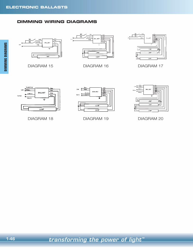
transforming the power of light™1-46
DIMMING WIRING DIAGRAMS
DIAGRAM 15 DIAGRAM 16 DIAGRAM 17
DIAGRAM 18 DIAGRAM 19 DIAGRAM 20
ELECTRONIC BALLASTSDI
MM
ING
DIAG
RAM
S
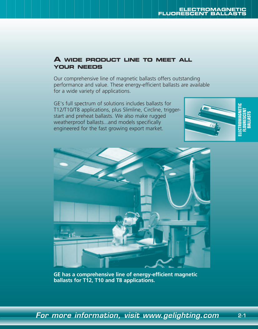
2-1For more information, visit www.gelighting.com
ELECTROMAGNETICFLUORESCENT BALLASTS
A WIDE PRODUCT LINE TO MEET ALLYOUR NEEDS
Our comprehensive line of magnetic ballasts offers outstanding performance and value. These energy-efficient ballasts are availablefor a wide variety of applications.
GE's full spectrum of solutions includes ballasts for T12/T10/T8 applications, plus Slimline, Circline, trigger-start and preheat ballasts. We also make rugged weatherproof ballasts...and models specifically engineered for the fast growing export market.
GE has a comprehensive line of energy-efficient magnetic ballasts for T12, T10 and T8 applications.
ELEC
TROM
AGN
ETIC
FLOU
RESC
ENT
BALL
ASTS

2-3For more information, visit www.gelighting.com
ELECROMAGNETICFLUORESCENT BALLASTS
transforming the power of light™2-2
ELECROMAGNETICFLUORESCENT BALLASTS
PRODUCT OVERVIEW PRODUCT OVERVIEW
Rapid StartBallasts
T12/10 Applications
Rapid Start BallastsThese ballasts provide smooth starting to rapid start
lamps – reaching full brightness in about two secondswithout the use of starters. They have built-in filamentwindings that energize the low-voltage cathodes in rapidstart lamps. Because electrodes are continuously heated,less voltage is required to strike an arc through a rapidstart lamp than a slimline one.
Ballasts for T12/T10 ApplicationsGE offers a wide variety of T12 and T10 ballasts to
operate 1-3 rapid start lamps. This lamp/ballast systemprovides smooth, virtually instant starting without the useof starters (30-and 40-watt T12 models and 40-watt T10models are available). Models for U-lamp applications arealso available. These “hybrid” type ballasts incorporate anelectronic switch which disconnects power to the lampcathodes after start-up, saving additional energy.
Ballasts for T8 ApplicationsGE‘s T8 product offering includes models for F17,
F25, F32 and F40 type T8 lamps. This product line fea-tures OcTek™ electromagnetic ballast models. These mod-els are low initial cost energy efficient options for usewith F32T8, 4-foot rapid start lamps. These models areavailable in several variations, including full, medium, lowlight output and hybrid versions (OkTek™ Plus). Thesemodels maximize energy savings and provide effectivechoices when retrofitting 4-foot T12 fixtures.
T8 Applications
Rapid Start DimmingBallasts
Slimline Ballasts
Rapid Start Dimming BallastsLight levels produced by fluorescent lamps can be
adjusted by using rapid start dimming ballasts in conjunction with proper control devices. These ballastsare generally for one- and two-lamp operation of 40-watt rapid start lamps – and they may also be used with 30-watt rapid start lamps. However, 30-watt lamps and40-watt lamps should not be mixed on the same dimming control. Different colors and brands of lamps,or different ballast brands, also should not be mixed onthe same dimming control. All dimming ballasts are recommended for use with phase controlled-type dimming controls only and subject to the approval of thedimming control manufacturer.
Slimline BallastsOur slimline models are designed for use with sin-
gle-pin slimline lamps. They do not require the use ofstarters. These ballasts deliver a high-starting voltage tothe lamps, enabling an arc to strike through the tubewithout preheating the lamp cathodes (which are specially constructed to withstand the shock).
Preheat Ballast Export (50/60 Hz) Ballast
Circline BallastsThese products are available in 430 mA rapid start
and preheat types, designed for use with circlinelamps. The operating characteristics are the same forboth circline and conventional lamps. All circline socketwires are fully sleeved.
Trigger-Start BallastsThese ballasts are designed for use with general
fluorescent lamps and do not require the use ofstarters. They contain preheat windings which allowregular lamp filaments to be heated in one second.However, they require a higher open-circuit voltagethan rapid start ballasts.
Preheat BallastsThese units are designed for use with general
fluorescent lamps and require the use of starters. Theseballasts deliver an open-circuit voltage high enough toactivate the starter to preheat lamp filaments to a temperature approximately 1750°F. After a few sec-onds, the starter opens the filament circuit. This pro-vides an additional power surge to enable an electricarc to strike through the lamp and ignite it. Lamp cur-rent is then limited by the ballast to an operating levelproper for the lamp.
Weatherproof BallastsBallasts designated as “weatherproof” are designed
to withstand direct exposure to rain and snow and areUnderwriters Laboratories, Inc.–approved for this pur-pose. The weatherproof ballasts listed within the cata-log are enclosed in a round extruded aluminum canwith the cover sealed be a double-rolled seam. It issupplied with a detached aluminum mounting bracketcontaining four keyholes and a stainless steel band witha threaded fastener. The mounting bracket can be locat-ed at any point on the cylinder portion of the ballast.There is no junction box supplied with the ballast. Astandard 3/4", 14 N.P. thread nipple is provided at oneend of the ballast to allow for the selection of a weath-ertight junction box most applicable to the particularneeds and local electrical code requirements.
Export (50/60 Hz) BallastsOur export product offering consists of a variety of
one- and two-lamp models for rapid start, preheat,high output, slimline, and 1500 mA lamps. Included inthis product line are ballasts for 50 and 60 Hz applica-tions, including 110, 120, 127, 220, 230, 240, and277 Volts. Many of these models are available withresetting thermal protection.
PROD
UCT
OVER
VIEW
PROD
UCT
OVER
VIEW

Electromagnetic and hybrid ballasts may beremote mounted according to the table below:
2-5
ELECROMAGNETICFLUORESCENT BALLASTS
transforming the power of light™2-4
ELECROMAGNETICFLUORESCENT BALLASTS
APPLICATION AND OPERATING INFORMATION APPLICATION AND OPERATING INFORMATION
VOLTAGE RANGEMinimum
110205220255315450570
Maximum125232250290364505630
Nominal Voltage120220240277347480600
Wire size 30-40 WattRapid Start
800 mA - HO1500 mA - VHO
Instant Start(Slimline)
Red/BlueLeads
YellowLeads
Red/BlueLeads
YellowLeads
#6#8
#10#12#14#16#18
All Leads
544'340'214'134'84'52'30'
384'240'150'94'60'36'20'
272'170'107'67'42'26'21'
192'120'75'47'30'18'15'
544'340'214'134'84'52'30'
For more information, visit www.gelighting.com
APPL
ICAT
ION
AN
D OP
ERAT
ING
INFO
RMAT
ION
APPL
ICAT
ION
AN
D OP
ERAT
ING
INFO
RMAT
ION
SAFETY
NEC & UL RequirementsBallast installation presents the possibility of
exposure to potentially hazardous voltages andshould be performed only by qualified personnel.All installation, inspection, and maintenanceshould be performed only with power to thefixture turned off. Additionally, all fixtures andballasts must be installed and operated in compli-ance with the National Electrical Code, UnderwritersLaboratories Inc. (UL) requirements, and all localapplicable codes and regulations.
PolarityPolarity refers to the proper connection of bal-
last lead wires to line wires. To aid you in making acorrect installation, GE ballast leads are color-codedfor easy identification. The WHITE ballast lead is tobe connected to the neutral (grounded) and theBLACK (or black with white tracer) lead always tothe phase (“hot”) line wire. Systems where neitherof the line wires are at ground potential requirespecially designed ballasts. A change in polarity mayresult in the voltage from the lead to the groundexceeding UL-specified limits. In some types of bal-lasts, a change in polarity may decrease voltagefrom the lead to the ground, thereby impeding thestarting dependability of the ballast.
GroundingBallast cases and fixtures must always be
grounded. The ballast case may be grounded to thefixture or otherwise grounded. It could be haz-ardous to make contact with an ungrounded fixtureor ballast when in operation. Neglecting to properlyground the ballast and fixture combination may alsoresult in failure of certain lamps to start or for unac-ceptable levels of electromagnetic noise to be con-ducted onto the power lines.
Operating Line Voltage LimitsTo receive the full benefits of rated lamp output
and to prolong ballast life, it is essential that voltagesupplied to an installation be maintained within lim-its prescribed for each circuit. These limits are listedin the next column.
Subjecting a ballast to excessive voltage for anextended period results in the deterioration of theinsulation. This insulation breakdown will cause earlyballast failure.
Low voltage has no damaging effect on the bal-last. However, lamps may not start reliably, and earlylamp failure could result.
Internal Ballast ProtectionClass P Classification – Since January 1, 1984, the
National Electrical Code requires that “whereFluorescent fixtures are installed indoors, the ballastshall have thermal protection integral within the bal-last except for simple reactance ballasts.” This rulingapplies to replacement ballasts as well as to thosecontained within new light fixtures.
In compliance with the National Electrical Code,UL has established a Class P ballast classification forfluorescent light fixtures indoors. A Class P ballastmust employ internal thermal protection limiting itsoperating temperature.
GE UL-approved Class P ballasts comply with theNational Electrical Code requirement and areequipped with an automatic resetting thermal protec-tor, built-in and adjacent to the transformer coils. Theresetting thermal protector functions as a thermostat,which will open and temporarily deactivate the bal-last when it exceeds the permissible temperature. Itwill reset when the ballast cools to a safe operatingtemperature. The ballast will continue to cycle untilthe cause of overheating is eliminated. If the ballast isdefective, it must be replaced. If the cause is external,a Class P ballast will resume normal operation afterabnormal conditions are eliminated.
FusingClass P ballasts do not require fusing. Fusing can
be used when a single circuit has a large number offixtures/ballasts. For more information, contact yourGE Lighting representative or visitwww.gelighting.com.
PERFORMANCE
Lamp ConnectionsElectromagnetic fluorescent ballasts are designed
to generate voltages in excess of 300 Volts. It isimperative that proper connection to good qualitysockets be assured in accordance with wiring dia-grams throughout this catalog and on product labels.Some applications may not require the use of all ofthe ballast output leads. If any leads are not to beconnected, each should be individually capped andinsulated to at least 600 Volts.
Application VersatilityMany GE models are designed to allow for appli-
cations with different types or quantities of lamps.Use of products other than noted is not covered byUL Listing and/or CSA certification and cannot bewarranted.
Audible Noise (Sound)Electrical equipment, including most fluorescent
lamp ballasts, produces some noise. Care must betaken to select a ballast with the proper sound ratingfor a particular lighting installation. Ballast sound willbe noticeable only when it exceeds the ambientsound level.
Although no industry standards currently exist,the generally accepted criteria for sound rating speci-fications are as follows:
Remote MountingExcessive hot or cold temperatures, audible
noise requirements, or a desire to operate lamps in more than one fixture with the same ballast (master/slave), may make it desirable to mount theballast remotely. Care must be taken to allow forballast heat dissipation and proper grounding.
In any application, the wire used to extendleads must be at least as large as the wire suppliedon the ballast (18 AWG) with an insulation ratingof 1000 VAC at 90°C. Lead lengths in excess ofthose noted cause loading effects that can dra-matically impact ballast performance and void thewarranty.
Operating TemperatureMost fluorescent ballasts and lamps are designed
to provide optimum performance at an ambient tem-perature of 77°F. Three key performance attributescan be impacted by the ambient (room) temperatureof the installation:
• Lamp Starting DependabilityFluorescent lamps are inherently more difficult tostart at low temperatures. All ballasts have limi-tations as to their ability to start lamps at lowambient temperatures. In this catalog, the lowstarting point for each lamp/ballast combinationappears in the column marked ”MinimumStarting Temperature.“
• Light OutputOptimum light output from fluorescent lampsis achieved when the lamp wall is at 100-110°F. Any substantial excursion (either colderor warmer) will result in a reduction in lightoutput.
• Ballast LifeA fluorescent lamp ballast, like any other elec-trical device, generates heat during its normaloperation. Ballast temperatures should be keptas low as possible. Maximum dissipation ofheat through fixture design and proper bal-last installation will help. Although excessivetemperature may not cause the ballast to failimmediately, it can shorten ballast life. Toassure maximum life, the ballast case temper-ature should not exceed 90°C.
Location Average BallastAmbient Noise Recommendation
Typical Office < 30 decibels ANoisy Office or Retail 31-36 decibels B
Factory, Outdoor > 36 decibels C

2-7For more information, visit www.gelighting.com
ELECROMAGNETICFLUORESCENT BALLASTS
transforming the power of light™2-6
ELECROMAGNETICFLUORESCENT BALLASTS
APPLICATION AND OPERATING INFORMATION SPECIFICATIONS
Other ballasts can also be manufactured to meetlow-leakage requirements. Consult GE for completeinformation regarding low-leakage ballasts.
TYPE 1 BALLASTS
All GE outdoor non-weatherproof magneticballasts (except those for sign applications) aredesigned to meet UL requirements for Type 1 use(metal enclosure required for wet or damp locations).
BALLASTS FOR GERMICIDAL LAMPS
GE manufactures ballasts to operate germicidallamps. When ordering, make sure the ANSI designation of the germicidal lamp matches exactlywith the ballast's recommended application.Several typically encountered germicidal lamps arelisted below along with the proper GE ballast fortheir operation.
Contact GE Lighting for additional information or applications not listed.
LampsLine
Voltage@60Hz
MaximumLeakage
To Ground
Catalog Number
(2)F30T12/RS 120 20uA 86251 573-L-TC-P-IP(1)F40T12/RS 120 30uA 86101 412-L-SLH-TC-P-IP(2)F40T12/RS 120 30uA 86137 446-L-SLH-TC-P(1)F40T12/RS 277 50uA 96158 458-L-SLH-TC-P-IP(2)F40T12/RS 277 50uA 86123 443-L-SLH-TC-P
GermicidalLamp GE Ballast See Page
Number(1)G15T8 200-H2 2-19 - 2-20
1. Ballasts shall be certified energy savingmagnetic type and operate lamps at afrequency of 60 Hz.
2. Ballasts shall be specifically designed tooperate (Quantity & Type) lamps.
3. Ballasts shall operate from 60 Hz inputsource of _______ Volts*, and toleratesustained variations of +5%-10% withno damage to the ballasts.
4. Ballasts shall provide transient immunity asrecommended by ANSI C62.41-1991,Location Category A1.
5. Ballasts shall provide starting sequenceconsistent with ANSI standard C82.1.
6. Ballasts shall tolerate sustained open cir-cuit and short circuit output conditionswith no damage to the ballasts.
7. Ballasts shall be: • UL LISTED as Class P and for use in
indoor or Type 1 outdoor applications.• CSA CERTIFIED where applicable
(120 and 347 Volt models).8. Ballasts shall tolerate operation, in most
fixtures, at ambient temperatures up to105°F (40°C). Ballast enclosure is limitedto 90°C maximum temperature.
9. Ballasts shall have a Power Factor greaterthan .90.
10.Lamp Current Crest Factor (ratio of peak toRMS current) shall be 1.7 or less in accordancewith lamp manufacturers recommendationand ANSI C82.11-1993.
• 1.85 or less for instant start Slimline (also per ANSI C82.1).
11.Ballasts shall have a Ballast Factor greaterthan .925 per ANSI C82.11-1993.
• .95 or greater for HO and VHO applications.
12. Input current Total Harmonic Distortionshall not exceed .32 per ANSI C82.1.
13.Ballasts shall be fully encapsulated (potted)to ensure maximum thermal and structuralintegrity.
14.Manufacturer shall provide written war-ranty against defects in material or work-manship.
15.Manufacturer shall have been manufac-turing electromagnetic ballasts for atleast twenty years.
16.Ballast shall be manufactured in NorthAmerica
17.GE model*______________ (or approved equal).
APPL
ICAT
ION
AN
D OP
ERAT
ING
INFO
RMAT
ION
GEProduct
Code
SPEC
IFIC
ATIO
NS
Operating Temperature, continued
Causes of ballast overheating:• Incorrect primary voltage or frequency• Incorrect size, type or number of lamps• Failed lamp starter• Incorrect wiring• Poor heat dissipation due to surrounding
insulation• Sealed (Vapor Tight) Fixtures - Unusual heat
build-up due to lack of ventilation in fixturesmay cause thermal (on/off) cycling of certainballasts. Consult GE for specific recommenda-tions.
Recommendations:• Selection of a proper ballast to match the
requirements of the lamp, fixture, voltage andinstallation
• Mounting of ballast within the fixture with asmuch surface contact as possible between theballast and metal portions of the fixture.
• The use of heat-conducting dissipators (radia-tors), if necessary, which increases surface contact between the ballast and fixture.
• If necessary, locate the ballast in a remote, cooler area outside the fixture.
• Planned lamp maintenance – the organizedreplacement of failed and failing lamps, particularly with preheat or slimline systems.
• Use of special LOW HEAT (-LH) rise, VERY LOWHEAT (-VLH) rise, and SUPER LOW HEAT (-SLH)rise ballasts where available and necessary.
LOW-LEAKAGE CURRENTTO GROUND BALLASTS
Many one- and two-lamp, 30- and 40-watt highpower rapid start ballasts, and two- and three-lamp20-watt trigger start ballasts, meet requirements for“low-leakage-current-to-ground.” Those most fre-quently used in low-leakage applications are listedin the next column.
All high power factor ballasts are equippedwith capacitators. Oil-filled capacitators
contain non-resetting internal protection and are manufactured without PCBs.
TYPICAL SPECIFICATIONS FOR ELECTROMAGNETIC BALLASTS

T12
2-9For more information, visit www.gelighting.com
Overall Dimensions Mounting DimensionsDraw # L W H M X
D1 6 7/16 1 7/8 1 1/2 6 -D2 9 1/2 2 3/8 1 1/2 8 57/64 1 11/16W
H
LM
D
GE Lamp Certification Line Input Ballast Min. F/CProduct Line Catalog Current Power Ballast Efficacy Crest THD Start Sound Wiring
Code Qty. Descr. Volts Number NOM (Amps) (Watts) Factor Factor Factor % Temp Rating Diag. Dim.F30T12 - High Power Factor
86287 1 Rapid 277 697-L-TC-P-IP • • .16 44 .98 2.23 < 1.7 < 20 50/10 A 42 D286251 2 Rapid 120 573-L-TC-P-IP • • .66 79 .95 1.21 < 1.7 < 20 50/10 A 1 D286253 2 Rapid 277 588-L-TC-P-IP • • .29 79 .96 1.21 < 1.7 < 20 50/10 A 1 D2
F30T12 - Normal Power Factor86105 1 Rapid 120 413-C-TC-P-IP • • • .63 37 .72 1.95 < 1.7 < 10 50/10 A 8 D1
F30T12/WM - High Power Factor86251 2 Rapid 120 573-L-TC-P-IP • • .57 67 .89 1.33 < 1.9 < 20 60/15 A 1 D286253 2 Rapid 277 588-L-TC-P-IP • • .26 70 .92 1.31 < 1.9 < 20 60/15 A 1 D2
F30T12 AND F30T12/WM LAMPS
GE Lamp Certification Line Input Ballast Min. F/CProduct Line Catalog Current Power Ballast Efficacy Crest THD Start Sound Wiring
Code Qty. Descr. Volts Number NOM (Amps) (Watts) Factor Factor Factor % Temp Rating Diag. Dim.F40T12 - High Power Factor
86101 1 Rapid 120 412-L-SLH-TC-P-IP★ • • • • • .45 52 .95 1.83 < 1.7 < 20 50/10 A 42 D286158 1 Rapid 277 458-L-SLH-TC-P-IP★ • • • • • .19 51 .95 1.86 < 1.7 < 20 50/10 A 42 D286110 2 Hybrid 120 420-L-TC-P-IP◆ • • • • .62 72 .85 1.18 < 1.7 < 20 50/10 A 1 D286137 2 Rapid 120 446-L-SLH-TC-P • • • • • .75 89 .94 1.06 < 1.7 < 20 50/10 A 1 D286208 2 Hybrid 277 537-L-TC-P-IP◆ • • • • .31 82 .94 1.15 < 1.7 < 20 50/10 A 1 D286123 2 Rapid 277 443-L-SLH-TC-P • • • • • .34 90 .95 1.06 < 1.7 < 20 50/10 A 1 D2
F40T12- Normal Power Factor 86105 1 Rapid 120 413-C-TC-P-IP❉ • • • .53 36 .61 1.69 < 1.7 < 20 50/10 A 8 D1
F40T12 LAMPS
★ Not for use with “U” lamps◆ Not for use with Energy Saver “U” lamps❉ For Residential Use Only
GE Lamp Certification Line Input Ballast Min. F/CProduct Line Catalog Current Power Ballast Efficacy Crest THD Start Sound Wiring
Code Qty. Descr. Volts Number NOM (Amps) (Watts) Factor Factor Factor % Temp Rating Diag. Dim.F40T12/WM - High Power Factor
86101 1 Rapid 120 412-L-SLH-TC-P-IP★ • • • • • .38 44 .88 2.00 < 1.9 < 20 60/15 A 42 D286158 1 Rapid 277 458-L-SLH-TC-P-IP★ • • • • • .17 44 .88 2.00 < 1.85 < 20 60/15 A 42 D286110 2 Hybrid 120 420-L-TC-P-IP◆ • • • • .50 59 .80 1.36 < 1.9 < 20 60/15 A 1 D286137 2 Rapid 120 446-L-SLH-TC-P • • • • • .65 74 .90 1.22 < 1.9 < 20 60/15 A 1 D286123 2 Rapid 277 443-L-SLH-TC-P • • • • • .28 74 .90 1.22 < 1.9 < 20 60/15 A 1 D286208 2 Hybrid 277 537-L-TC-P-IP◆ • • • • .26 70 .91 1.30 < 1.9 < 20 60/15 A 1 D2
F40T12/WM - Normal Power Factor86105 1 Rapid 120 413-C-TC-P-IP❉ • • • .61 33 .68 2.06 < 1.9 < 20 60/15 A 8 D1
F40T12/WM LAMPS
DIMENSIONS
★ Not for use with “U” lamps◆ Not for use with Energy Saver “U” lamps❉ For Residential Use Only
For more information, visit www.gelighting.com 2-9
ELECROMAGNETICFLUORESCENT BALLASTS
transforming the power of light™2-8
ELECROMAGNETICFLUORESCENT BALLASTS
LEAD
LEN
GTHS
Black Black/White White Red Blue Yellow Blue/White Brown
LEAD LENGTHS
CatalogNumber
GEProduct
Code Qua
ntit
y
Exit
Leng
th
Qua
ntit
y
Exit
Leng
th
Qua
ntit
y
Exit
Leng
th
Qua
ntit
y
Exit
Leng
th
Qua
ntit
y
Exit
Leng
th
Qua
ntit
y
Exit
Leng
th
Qua
ntit
y
Exit
Leng
th
Qua
ntit
y
Exit
Leng
th
86071 200-C-S-P-IP 1 R 13 2 R 13 1 R 27 1 R 27 1 R 2786073 200-H2-IP 2 8-1586078 202-B-TC-P-IP 1 L 8 1 L 27 1 R 2686080 202-SB-TC-IP 1 12 2 32-12 1 26 1 26 1 3286085 213-TC-P-IP 1 L 41 1 L 41 1 R 23 1 R 2386105 413-C-TC-P-IP 1 L 9 1 L 29 2 R 30 1 L 2986110 420-L-TC-P-IP 1 L 20 1 L 20 2 R 24 2 R 24 2 L 3686123 443-L-SLH-TC-P 1 L 22 1 L 22 2 R 26 2 R 26 2 L 3686132 445-RS-WS-TC-P-IP 1 L 10 2 L/R 10 2 R 9 1 R 986137 446-L-SLH-TC-P 1 L 22 1 L 22 2 R 26 2 R 26 2 L 3686144 447-LR-TC-P-IP 1 L 10 1 L 10 2 R 13 2 R 13 2 L 1886158 458-L-SLH-TC-P-IP 1 L 25 1 L 25 2 L 37 2 R 27 2 R 2786164 480-SLH-TC-P-IP 1 L 18 1 L 18 2 R 46 2 R 46 2 L 6586167 480-XLH-TC-P-IP 1 L 18 1 L 18 2 R 46 2 R 46 2 L 6586171 487-SLH-TC-P-IP 1 L 18 1 L 18 2 R 46 2 R 46 2 L 6586173 487-XLH-TC-P-IP 1 L 18 1 L 18 2 R 46 2 R 46 2 L 6586176 490-XLH-TC-P-IP 1 L 18 1 L 18 2 R 33 2 R 33 2 L 5186185 502-A-TC-P-IP 1 L 20 1 L 38 2 R 26 1 L 38 2 R 26 1 L 38 1 R 2086206 532-BR-TC-P-IP 1 L 10 1 L 42 1 R 27 1 R 27 2 L 4286208 537-L-TC-P-IP 1 L 20 1 L 20 2 R 24 2 R 24 2 L 3686222 546-B-TC-P-IP 1 L 10 1 L 17 2 R 12 1 L 1786227 547-RS-WS-TC-P-IP 1 L 10 2 L/R 10 2 R 9 1 R 986231 548-H2-IP 2 986240 554-L-TC-P-IP 1 L 10 1 L 10 2 R 13 2 R 13 2 L 1686243 562-L-TC-P-IP 1 L 10 1 L 10 2 L 10 2 R 1086245 564-L-TC-P-IP 1 L 10 1 L 10 2 R 13 2 R 13 2 L 1686251 573-L-TC-P-IP 1 L 22 1 L 22 2 R 25 2 R 25 2 L 2686253 588-L-TC-P-IP 1 L 22 1 L 22 2 R 25 2 R 25 2 L 2686264 627-LH-TC-P-IP 1 L 18 1 L 18 2 R 20 2 R 20 2 L 3286287 697-L-TC-P-IP 1 L 20 1 L 20 2 L 26 2 R 26 2 R 2386341 754-L-TC-P-IP 1 L 22 1 L 22 2 R 26 2 R 26 2 L 3686351 798-XLH-TC-P-IP 1 L 18 1 18 2 33 2 33 2 5186359 806-SLH-TC-P 1 L 68 1 L 68 1 R 44 1 R 4486372 822-BR-TC-P-IP 1 L 8 1 L 68 1 R 4486378 827-SLH-TC-P 1 L 68 1 L 68 1 R 44 1 R 45 2 L 61.586381 828-BR-TC-P-IP 1 8 1 L 68 1 R 4486396 881-BR-TC-P-IP 1 L 68 1 L 68 1 R 44 1 R 4486402 930-K-TC-P-IP 1 L 18 1 L 18 2 R 46 2 R 46 2 L 6586411 937-K-TC-P-IP 1 L 18 1 L 18 2 R 46 2 R 46 2 L 6586430 957-S-TC-P-IP 1 L 10 1 L 10 2 R 49 2 L 5286432 960-VLH-TC-P-IP 1 L 20 1 L 20 2 R 38 2 R 38 2 L 47
Lead Quantities (per color)Exits (L=Left, R=Right, B=Bottom)Lengths (in inches, +/- 1")

T10
2-11For more information, visit www.gelighting.com
ELECROMAGNETICFLUORESCENT BALLASTS
T12
transforming the power of light™2-10
FOR F40T10 LAMPS
Overall Dimensions Mounting DimensionsDraw # L W H M X
D2 9 1/2 2 3/8 1 1/2 8 57/64 1 11/16W
H
LM
D
DIMENSIONS
GE Lamp Certification Line Input Ballast Min. F/CProduct Line Catalog Current Power Ballast Efficacy Crest THD Start Sound Wiring
Code Qty. Descr. Volts Number NOM (Amps) (Watts) Factor Factor Factor % Temp Rating Diag. Dim.F40T10 - High Power Factor
86101 1 Rapid 120 412-L-SLH-TC-P-IP • • • • • .45 52 .90 1.73 < 1.7 < 20 50/10 A 42 D286158 1 Rapid 277 458-L-SLH-TC-P-IP • • • • • .19 51 .90 1.76 < 1.7 < 20 50/10 A 42 D286110 2 Hybrid 120 420-L-TC-P-IP • • • • .65 74 .85 1.15 < 1.7 < 32 50/10 A 1 D286137 2 Rapid 120 446-L-SLH-TC-P • • • • • .76 90 .95 1.06 < 1.7 < 20 50/10 A 1 D286123 2 Rapid 277 443-L-SLH-TC-P • • • • • .33 90 .95 1.06 < 1.7 < 20 50/10 A 1 D286208 2 Hybrid 277 537-L-TC-P-IP • • • • .32 85 .95 1.12 < 1.7 < 20 50/10 A 1 D2
ELECROMAGNETICFLUORESCENT BALLASTS
GE Lamp Certification Line Input Ballast Min. F/CProduct Line Catalog Current Power Ballast Efficacy Crest THD Start Sound Wiring
Code Qty. Descr. Volts Number NOM (Amps) (Watts) Factor Factor Factor % Temp Rating Diag. Dim.F40T12/U - High Power Factor
86110 2 Hybrid 120 420-L-TC-P-IP◆ • • • • .64 74 .83 1.12 < 1.7 < 32 50/10 A 1 D286137 2 Rapid 120 446-L-SLH-TC-P • • • • • .76 90 .93 1.03 < 1.7 < 20 50/10 A 1 D286208 2 Hybrid 277 537-L-TC-P-IP◆ • • • • .32 87 .94 1.08 < 1.7 < 20 50/10 A 1 D286123 2 Rapid 277 443-L-SLH-TC-P • • • • • .34 92 .95 1.03 < 1.7 < 20 50/10 A 1 D2
◆ Not for use with Energy Saver “U” lamps
F40T12/U LAMPS
FOR F40T12/WM/U, F48" 25W/UTLSAND WORKLITE 25 LAMPS
Overall Dimensions Mounting DimensionsDraw # L W H M X
D1 6 7/16 1 7/8 1 1/2 6 -D2 9 1/2 2 3/8 1 1/2 8 57/64 1 11/16W
H
LM
D
DIMENSIONS
GE Lamp Certification Line Input Ballast Min. F/CProduct Line Catalog Current Power Ballast Efficacy Crest THD Start Sound Wiring
Code Qty. Descr. Volts Number NOM (Amps) (Watts) Factor Factor Factor % Temp Rating Diag. Dim.F40T12/WM/U - High Power Factor
86137 2 Rapid 120 446-L-SLH-TC-P • • • • • .65 74 .90 1.22 < 1.9 < 20 60/15 A 1 D286123 2 Rapid 277 443-L-SLH-TC-P • • • • • .28 74 .90 1.22 < 1.9 < 20 60/15 A 1 D2
F48”25W/UTLS & WORKLITE - Normal Power Factor86105 1 Rapid 120 413-C-TC-P-IP❉ • • • .51 32 .90 2.79 < 1.7 < 20 50/10 A 8 D1
❉ For Residential Use Only

T12H
O
2-13For more information, visit www.gelighting.com
ELECROMAGNETICFLUORESCENT BALLASTS
transforming the power of light™2-12
FOR F72T12HO LAMPS
DIMENSIONSOverall Dimensions Mounting DimensionsDraw # L W H M X
D7 11 3/4 3 3/16 2 5/8 11 9/64 2W
H
LM
D
GE Lamp Certification Line Input Ballast Min. F/CProduct Line Catalog Current Power Ballast Efficacy Crest THD Start Sound Wiring
Code Qty. Descr. Volts Number NOM (Amps) (Watts) Factor Factor Factor % Temp Rating Diag. Dim.F72T12HO - High Power Factor
86174 1 Rapid 120 490-XLH-TC-P • • .95 107 .86 0.80 < 2.0 > 32 -20/-29 B 15 D786164 2 Rapid 120 480-SLH-TC-P-IP • • • • • 1.69 196 .97 0.49 < 1.9 < 20 -20/-29 B 1 D786167 2 Rapid 120 480-XLH-TC-P-IP • • 1.69 196 .97 0.49 < 1.9 < 20 -20/-29 B 1 D786174 2 Rapid 120 490-XLH-TC-P • • 1.50 177 .92 0.52 < 1.7 < 10 -20/-29 B 1 D786171 2 Rapid 277 487-SLH-TC-P-IP • • • • • .74 197 .96 0.48 < 1.7 < 20 -20/-29 B 1 D786173 2 Rapid 277 487-XLH-TC-P-IP • • .78 208 .95 0.46 < 1.7 < 20 -20/-29 B 1 D7
✜ Power Factor Corrected to >85%
FOR F72T12HO LAMPS
See product overview pages for electromagnetic fluorescent ballasts for additional information on weatherproof applications.
GE Lamp Certification Line Input Ballast Min. F/CProduct Line Catalog Current Power Ballast Efficacy Crest THD Start Sound Wiring
Code Qty. Descr. Volts Number NOM (Amps) (Watts) Factor Factor Factor % Temp Rating Diag. Dim.F72T12HO - High Power Factor - Tanning
86351 2 Rapid 120 798-XLH-TC-P-IP • • 1.89 224 1.06 0.47 < 1.7 < 20 50/10 B 1 D7
GE Lamp Certification Line Input Ballast Min. F/CProduct Line Catalog Current Power Ballast Efficacy Crest THD Start Sound Wiring
Code Qty. Descr. Volts Number NOM (Amps) (Watts) Factor Factor Factor % Temp Rating Diag. Dim.F84T12HO - High Power Factor
86164 2 Rapid 120 480-SLH-TC-P-IP • • • • • 1.87 220 .93 0.42 < 1.9 < 20 -20/-29 B 1 D786167 2 Rapid 120 480-XLH-TC-P-IP • • 1.98 235 .93 0.40 < 1.9 < 20 -20/-29 B 1 D786171 2 Rapid 277 487-SLH-TC-P-IP • • • • • .87 235 .97 0.41 < 1.9 < 20 -20/-29 B 1 D786173 2 Rapid 277 487-XLH-TC-P-IP • • .89 244 .95 0.39 < 1.9 < 20 -20/-29 B 1 D7
FOR F84T12HO LAMPS
FOR F96T12HO AND F96T12HO/WM LAMPS
GE Lamp Certification Line Input Ballast Min. F/CProduct Line Catalog Current Power Ballast Efficacy Crest THD Start Sound Wiring
Code Qty. Descr. Volts Number NOM (Amps) (Watts) Factor Factor Factor % Temp Rating Diag. Dim.F96T12HO - High Power Factor
86174 1 Rapid 120 490-XLH-TC-P • • 1.10 124 .85 0.65 < 2.0 < 20 -20/-29 B 15 D786164 2 Rapid 120 480-SLH-TC-P-IP • • • • • 1.99 237 .96 0.41 < 1.7 < 10 -20/-29 B 1 D786167 2 Rapid 120 480-XLH-TC-P-IP • • 2.15 250 .96 0.39 < 1.7 < 10 -20/-29 B 1 D786171 2 Rapid 277 487-SLH-TC-P-IP • • • • • .87 237 .95 0.40 < 1.7 < 10 -20/-29 B 1 D786173 2 Rapid 277 487-XLH-TC-P-IP • • .95 261 .97 0.37 < 1.7 < 10 -20/-29 B 1 D7
F96T12HO/WM - High Power Factor 86174 1 Rapid 120 490-XLH-TC-P • • .94 106 .81 0.76 < 2.0 < 32 60/15 B 15 D786164 2 Rapid 120 480-SLH-TC-P-IP • • • • • 1.72 202 .89 0.44 < 1.9 < 20 60/15 B 1 D786167 2 Rapid 120 480-XLH-TC-P-IP • • 1.80 209 .89 0.43 < 1.9 < 20 60/15 B 1 D786171 2 Rapid 277 487-SLH-TC-P-IP • • • • • .75 205 .91 0.44 < 1.9 < 20 60/15 B 1 D786173 2 Rapid 277 487-XLH-TC-P-IP • • .83 223 .92 0.41 < 1.9 < 20 60/15 B 1 D7
For more information, visit www.gelighting.com
ELECROMAGNETICFLUORESCENT BALLASTS
T12H
O
W
H
LM
D
FOR F24, F30, F36 ANDF42T12HO LAMPS
FOR F48T12HO LAMPS
DIMENSIONSOverall Dimensions Mounting DimensionsDraw # L W H M X
D6 11 3/4 3 1/8 1 25/32 11 9/64 2D7 11 3/4 3 3/16 2 5/8 11 9/64 2
GE Lamp Certification Line Input Ballast Min. F/CProduct Line Catalog Current Power Ballast Efficacy Crest THD Start Sound Wiring
Code Qty. Descr. Volts Number NOM (Amps) (Watts) Factor Factor Factor % Temp Rating Diag. Dim.F24T12HO - High Power Factor
86174 2 Rapid 120 490-XLH-TC-P • • .95 103 .81 0.79 < 2.0 > 32 -20/-29 B 1 D786264 2 Rapid 277 627-LH-TC-P-IP • • .40 103 .94 0.91 < 1.9 < 32 50/10 B 1 D6
F36T12HO - High Power Factor86174 2 Rapid 120 490-XLH-TC-P • • 1.06 121 .84 0.69 < 2.0 < 32 50/10 B 1 D786264 2 Rapid 277 627-LH-TC-P-IP • • .48 128 .98 0.77 < 1.7 < 20 50/10 B 1 D6
F42T12HO - High Power Factor86174 2 Rapid 120 490-XLH-TC-P • • 1.12 130 .86 0.66 < 2.0 < 32 50/10 B 1 D786264 2 Rapid 120 627-LH-TC-P-IP • • .51 139 .98 0.71 < 1.7 < 20 50/10 B 1 D6
GE Lamp Certification Line Input Ballast Min. F/CProduct Line Catalog Current Power Ballast Efficacy Crest THD Start Sound Wiring
Code Qty. Descr. Volts Number NOM (Amps) (Watts) Factor Factor Factor % Temp Rating Diag. Dim.F48T12HO - High Power Factor
86174 1 Rapid 120 490-XLH-TC-P▼ • • .82 82 .81 0.99 < 2.0 > 32 -20/-29 B 15 D786174 2 Rapid 120 490-XLH-TC-P • • 1.18 139 .87 0.63 < 2.0 < 20 -20/-29 B 1 D786264 2 Rapid 277 627-LH-TC-P-IP • • .55 150 .99 0.66 < 1.7 < 20 50/10 B 1 D6
▼ Power Factor Corrected to >70%
FOR F48T12HO/WM ANDF60T12HO LAMPS
FOR F60 AND F64T12HO LAMPS
GE Lamp Certification Line Input Ballast Min. F/CProduct Line Catalog Current Power Ballast Efficacy Crest THD Start Sound Wiring
Code Qty. Descr. Volts Number NOM (Amps) (Watts) Factor Factor Factor % Temp Rating Diag. Dim.F48T12HO/WM - High Power Factor
86174 1 Rapid 120 490-XLH-TC-P▼ • • .80 76 .78 1.03 < 2.0 > 32 60/15 B 15 D786174 2 Rapid 120 490-XLH-TC-P • • 1.07 124 .83 0.67 < 2.0 < 32 60/15 B 1 D786264 2 Rapid 277 627-LH-TC-P-IP • • .49 131 .92 0.70 < 1.9 < 20 60/15 B 1 D6
F60T12HO - High Power Factor 86174 1 Rapid 120 490-XLH-TC-P • • .92 99 .83 0.84 < 2.0 > 32 -20/-29 B 15 D786174 2 Rapid 120 490-XLH-TC-P • • 1.42 169 .89 0.53 < 2.0 < 20 -20/-29 B 1 D7
▼ Power Factor Corrected to >70%
GE Lamp Certification Line Input Ballast Min. F/CProduct Line Catalog Current Power Ballast Efficacy Crest THD Start Sound Wiring
Code Qty. Descr. Volts Number NOM (Amps) (Watts) Factor Factor Factor % Temp Rating Diag. Dim.F64T12HO - High Power Factor
86174 1 Rapid 120 490-XLH-TC-P • • .93 101 .84 0.83 < 1.9 > 32 -20/-29 B 15 D786174 2 Rapid 120 490-XLH-TC-P • • 1.50 178 .89 0.50 < 1.9 < 20 -20/-29 B 1 D7

T12V
HO
2-15For more information, visit www.gelighting.com
ELECROMAGNETICFLUORESCENT BALLASTS
transforming the power of light™2-14
FOR F96T12VHO ANDF96T12VHO/WM LAMPS
FOR F96PG17 ANDF96PG17/WM LAMPS
GE Lamp Certification Line Input Ballast Min. F/CProduct Line Catalog Current Power Ballast Efficacy Crest THD Start Sound Wiring
Code Qty. Descr. Volts Number NOM (Amps) (Watts) Factor Factor Factor % Temp Rating Diag. Dim.F96PG17 - High Power Factor
86430 1 Rapid 277 957-S-TC-P-IP • • .83 192 .79 0.41 < 1.9 < 32 -20/-29 C 12 D886402 2 Rapid 120 930-K-TC-P-IP❷ • • 3.83 446 .98 0.22 < 1.7 < 20 -20/-29 D 1 D886411 2 Rapid 277 937-K-TC-P-IP❷ • • 1.61 429 .95 0.22 < 1.7 < 20 -20/-29 D 1 D8
F96PG17/WM - High Power Factor 86430 1 Rapid 277 957-S-TC-P-IP • • .79 175 .76 0.43 < 1.9 < 32 60/15 C 12 D8
❷ Cannot be used with T10 or T10J lamps
DIMENSIONS
W
H
LM
D
See product overview pages for electromagnetic fluorescent ballasts for additional information on weatherproof applications.
Overall Dimensions Mounting DimensionsDraw # L W H M X
D8 14 5/16 3 3/16 2 5/8 13 3/4 2
GE Lamp Certification Line Input Ballast Min. F/CProduct Line Catalog Current Power Ballast Efficacy Crest THD Start Sound Wiring
Code Qty. Descr. Volts Number NOM (Amps) (Watts) Factor Factor Factor % Temp Rating Diag. Dim.F96T12VHO - High Power Factor
86430 1 Rapid 277 957-S-TC-P-IP▼ • • .81 197 .78 0.40 < 1.9 < 32 -20/-29 C 12 D886402 2 Rapid 120 930-K-TC-P-IP❷ • • 4.10 482 .99 0.21 < 1.7 < 20 -20/-29 D 1 D886411 2 Rapid 277 937-K-TC-P-IP❷ • • 1.64 450 .95 0.21 < 1.7 < 20 -20/-29 D 1 D8
F96T12VHO/WM - High Power Factor 86430 1 Rapid 277 957-S-TC-P-IP▼ • • .79 183 .77 0.42 < 1.9 < 32 60/15 C 12 D8
▼ Power Factor Corrected to >70%❷ Cannot be used with T10 or T10J lamps
For more information, visit www.gelighting.com
T12V
HOELECROMAGNETIC
FLUORESCENT BALLASTS
DIMENSIONS
W
H
LM
D
GE Lamp Certification Line Input Ballast Min. F/CProduct Line Catalog Current Power Ballast Efficacy Crest THD Start Sound Wiring
Code Qty. Descr. Volts Number NOM (Amps) (Watts) Factor Factor Factor % Temp Rating Diag. Dim.F48PG17 - High Power Factor
86432 2 Rapid 120 960-VLH-TC-P-IP① • • 1.60 175 .70 0.40 < 2.0 < 32 -20/-29 C 1 D8F48T12VHO - High Power Factor
86432 2 Rapid 120 960-VLH-TC-P-IP① • • 1.62 185 .72 0.39 < 2.0 < 32 -20/-29 C 1 D8
① May be used with equivalent T10 or T10J lamps.
FOR F48PG17 ANDF48T12VHO LAMPS
See product overview pages for electromagnetic fluorescent ballasts for additional information on weatherproof applications.
GE Lamp Certification Line Input Ballast Min. F/CProduct Line Catalog Current Power Ballast Efficacy Crest THD Start Sound Wiring
Code Qty. Descr. Volts Number NOM (Amps) (Watts) Factor Factor Factor % Temp Rating Diag. Dim.F72PG17 - High Power Factor
86430 1 Rapid 277 957-S-TC-P-IP▼ • • .76 157 .77 0.49 < 1.9 > 32 -20/-29 C 12 D886402 2 Rapid 120 930-K-TC-P-IP❷ • • 3.05 360 .95 0.26 < 1.7 < 20 -20/-29 D 1 D886432 2 Rapid 120 960-VLH-TC-P-IP① • • 2.01 239 .72 0.30 < 1.9 < 20 -20/-29 C 1 D886411 2 Rapid 277 937-K-TC-P-IP❷ • • 1.26 341 .92 0.27 < 1.7 < 20 -20/-29 D 1 D8
F72T12VHO - High Power Factor 86430 1 Rapid 277 957-S-TC-P-IP▼ • • .75 161 .79 0.49 < 1.9 > 32 -20/-29 C 12 D886402 2 Rapid 120 930-K-TC-P-IP❷ • • 3.05 360 .95 0.26 < 1.7 < 20 -20/-29 D 1 D886432 2 Rapid 120 960-VLH-TC-P-IP① • • 2.08 248 .79 0.32 < 1.9 < 20 -20/-29 C 1 D886411 2 Rapid 277 937-K-TC-P-IP❷ • • 1.26 341 .91 0.27 < 1.7 < 20 -20/-29 D 1 D8
▼ Power Factor Corrected to >70%❷ Cannot be used with T10 or T10J lamps① May be used with equivalent T10 or T10J lamps
Overall Dimensions Mounting DimensionsDraw # L W H M X
D8 14 5/16 3 3/16 2 5/8 13 3/4 2
FOR F72PG17 ANDF72T12VHO LAMPS

2-17For more information, visit www.gelighting.com
ELECROMAGNETICFLUORESCENT BALLASTS
transforming the power of light™2-16
T12
SLIM
LIN
E
DIMENSIONS
W
H
LM
D
Overall Dimensions Mounting DimensionsDraw # L W H M X
D6 11 3/4 3 1/8 1 25/32 11 9/64 2D12 11 3/4 3 3/16 1 25/32 11 9/64 2
GE Lamp Certification Line Input Ballast Min. F/CProduct Line Catalog Current Power Ballast Efficacy Crest THD Start Sound Wiring
Code Qty. Descr. Volts Number NOM (Amps) (Watts) Factor Factor Factor % Temp Rating Diag. Dim.F96T12 - High Power Factor
86372 1 Instant 120 822-BR-TC-P-IP • • • .84 96 .95 0.98 < 1.85 < 32 0/-18 C 34 D686381 1 Instant 277 828-BR-TC-P-IP • • .35 93 .93 1.00 < 1.85 < 32 0/-18 C 34 D686378 2 Instant 277 827-SLH-TC-P-IP • • • • • .58 158 .93 0.59 < 1.85 < 10 50/10 C 40 D12
F96T12/WM - High Power Factor 86372 1 Instant 120 822-BR-TC-P-IP • • • .70 79 .90 1.14 < 2.0 < 32 60/15 C 34 D686381 1 Instant 277 828-BR-TC-P-IP • • .30 79 .96 1.22 < 2.0 < 32 60/15 C 34 D686378 2 Instant 277 827-SLH-TC-P-IP • • • • • .48 132 .89 0.67 < 2.0 < 20 60/15 C 40 D12
FOR F96T12 ANDF96T12/WM LAMPS
For more information, visit www.gelighting.com
T12
SLIM
LIN
EELECROMAGNETIC
FLUORESCENT BALLASTS
DIMENSIONS
W
H
LM
D
Overall Dimensions Mounting DimensionsDraw # L W H M X
D6 11 3/4 3 1/8 1 25/32 11 9/64 2D10 9 29/64 3 3/32 1 25/32 8 57/64 1 11/16D12 11 3/4 3 3/16 1 25/32 11 9/64 2
GE Lamp Certification Line Input Ballast Min. F/CProduct Line Catalog Current Power Ballast Efficacy Crest THD Start Sound Wiring
Code Qty. Descr. Volts Number NOM (Amps) (Watts) Factor Factor Factor % Temp Rating Diag. Dim.F24T12 - High Power Factor
86206 2 Instant 277 532-BR-TC-P-IP◗ • • .29 60 .96 1.60 < 1.85 < 32 32 / 0 B 40 D6F36T12 - High Power Factor
86085 2 Instant 120 213-TC-P-IP • • • .70 77 .95 1.24 < 1.85 > 32 50/10 B 39 D1086206 2 Instant 277 532-BR-TC-P-IP◗ • • .34 75 .93 1.24 < 1.85 < 32 32 / 0 B 40 D12
F40T12 /IS - Bi Pin - High Power Factor 86085 2 Instant 120 213-TC-P-IP • • • .80 94 .92 0.98 < 1.85 < 20 50/10 B 39 D1086206 2 Instant 277 532-BR-TC-P-IP • • .37 94 .92 0.98 < 1.85 < 32 32 / 0 B 40 D12
F42T12 - High Power Factor 86085 2 Instant 120 213-TC-P-IP • • • .74 86 .93 1.09 < 2.0 < 32 50/10 B 39 D1086206 2 Instant 277 532-BR-TC-P-IP • • .34 84 .94 1.11 < 1.85 < 32 32 / 0 B 40 D12
F48T12 - High Power Factor 86085 2 Instant 120 213-TC-P-IP • • • .79 95 .92 0.89 < 1.85 < 20 50/10 B 39 D1086206 2 Instant 277 532-BR-TC-P-IP • • .35 95 .96 1.01 < 1.85 < 32 32 / 0 B 40 D12
F48T12/WM - High Power Factor 86085 2 Instant 120 213-TC-P-IP • • • .72 80 .91 1.14 < 2.0 < 32 60/15 B 39 D1086206 2 Instant 277 532-BR-TC-P-IP • • .32 82 .94 1.15 < 2.0 < 32 60/15 B 40 D12
◗Power Factor Corrected to >75%
FOR F24 - F48T12 LAMPS
FOR F60 - F84T12 LAMPSGE Lamp Certification Line Input Ballast Min. F/C
Product Line Catalog Current Power Ballast Efficacy Crest THD Start Sound WiringCode Qty. Descr. Volts Number NOM (Amps) (Watts) Factor Factor Factor % Temp Rating Diag. Dim.
F60T12 - High Power Factor 86396 2 Instant 120 881-BR-TC-P-IP❏ • • .96 109 .84 0.77 < 1.85 < 32 0/-18 C 39 D6
F64T12 - High Power Factor 86396 2 Instant 120 881-BR-TC-P-IP❏ • • 1.05 119 .84 0.71 < 1.85 < 32 0/-18 C 39 D6
F72T12 - High Power Factor 86372 1 Instant 120 822-BR-TC-P-IP • • • .72 81 .95 1.17 < 1.85 < 32 0/-18 C 34 D686381 1 Instant 277 828-BR-TC-P-IP • • .30 78 .92 1.18 < 1.85 < 32 0/-18 C 34 D686359 2 Instant 120 806-SLH-TC-P • • • • • 1.13 133 1.01 0.76 < 1.85 < 20 50/10 C 39 D686396 2 Instant 120 881-BR-TC-P-IP • • 1.03 120 .82 0.69 < 1.85 < 32 0/-18 C 39 D686378 2 Instant 277 827-SLH-TC-P-IP • • • • • .49 135 .93 0.69 < 1.85 < 20 50/10 C 40 D12
F84T12 - High Power Factor 86372 1 Instant 120 822-BR-TC-P-IP • • • .77 89 .96 1.09 < 1.85 < 32 0/-18 C 34 D686381 1 Instant 277 828-BR-TC-P-IP • • .33 86 .94 1.09 < 1.85 < 32 0/-18 C 34 D686359 2 Instant 120 806-SLH-TC-P • • • • • 1.26 143 .95 0.67 < 1.85 < 20 50/10 C 39 D686378 2 Instant 277 827-SLH-TC-P-IP • • • • • .55 150 .95 0.63 < 1.85 < 10 50/10 C 40 D12
❏ Use with any combination of F60T12 & F64T12

2-19For more information, visit www.gelighting.com
ELECROMAGNETICFLUORESCENT BALLASTS
transforming the power of light™2-18
PREH
EAT/
TRIG
GER
DIMENSIONS
W
H
LM
D
L
L
M
M
W
3/32" Slots
E
H
GE Lamp Certification Line Input Ballast Min. F/CProduct Line Catalog Current Power Ballast Efficacy Crest THD Start Sound Wiring
Code Qty. Descr. Volts Number NOM (Amps) (Watts) Factor Factor Factor % Temp Rating Diag. Dim.F4T5 - Normal Power Factor
86231 1 Preheat 120 548-H2-IP❶ • • .17 8 1.00 12.5 < 1.7 <10 50/10 A 21 E1
❶ Requires Starter
Overall Dimensions Mounting DimensionsDraw # L W H M X
D1 6 7/16 1 7/8 1 1/2 6 -D2 9 1/2 2 3/8 1 1/2 8 57/64 1 11/16D3 6 19/32 2 3/8 1 1/2 6 -D11 6 7/16 1 7/8 1 5/16 6 -E1 3 1/16 1 25/32 1 5/16 2 3/4 -
FOR F4 AND F6T5 LAMPS
GE Lamp Certification Line Input Ballast Min. F/CProduct Line Catalog Current Power Ballast Efficacy Crest THD Start Sound Wiring
Code Qty. Descr. Volts Number NOM (Amps) (Watts) Factor Factor Factor % Temp Rating Diag. Dim.F14T8 - Normal Power Factor
86071 1 Preheat 120 200-C-S-P-IP♣ • • .42 22 1.07 4.89 < 1.7 <10 50/10 A 28 D1186073 1 Preheat 120 200-H2-IP❶ • • • .36 19 .99 5.15 < 1.7 <10 50/10 A 21 E1
F14T12 - Normal Power Factor 86243 1 Preheat 277 562-L-TC-P-IP • • .11 28 .75 2.68 < 2.0 <32 50/10 A 12 D286245 2 Preheat 120 564-L-TC-P-IP • • • .39 45 .79 1.75 < 1.7 <20 50/10 A 1 D286240 2 Preheat 277 554-L-TC-P-IP • • .17 45 .79 1.76 < 1.9 <20 50/10 A 1 D2
F14T12 - Normal Power Factor 86071 1 Preheat 120 200-C-S-P-IP♣ • • .43 22 1.11 4.96 < 1.7 <10 50/10 A 28 D1186073 1 Preheat 120 200-H2-IP❶ • • • .37 20 .98 4.85 < 1.7 <10 50/10 A 21 E186222 1 Preheat 120 546-B-TC-P-IP♠ • • • .66 30 .86 2.87 < 1.7 <10 50/10 A 8 D1
♣ Starter is built in as an integral component♠ Requires one circuit interrupting lamp holder❶ Requires Starter
FOR F14T8 AND F14T12 LAMPS
FOR F15T8 LAMPSGE Lamp Certification Line Input Ballast Min. F/C
Product Line Catalog Current Power Ballast Efficacy Crest THD Start Sound WiringCode Qty. Descr. Volts Number NOM (Amps) (Watts) Factor Factor Factor % Temp Rating Diag. Dim.
F15T8 - High Power Factor 86243 1 Preheat 277 562-L-TC-P-IP • • .12 28 .88 3.16 < 2.0 <32 50/10 A 12 D286245 2 Preheat 120 564-L-TC-P-IP • • • .47 51 .91 1.78 < 1.7 <32 50/10 A 1 D286240 2 Preheat 277 554-L-TC-P-IP • • .20 51 .89 1.76 < 1.9 <20 50/10 A 1 D2
F15T8 - Normal Power Factor 86071 1 Preheat 120 200-C-S-P-IP♣ • • .36 22 1.05 4.86 < 1.7 <10 50/10 A 28 D1186073 1 Preheat 120 200-H2-IP❶ • • • .32 20 1.05 5.13 < 1.7 <10 50/10 A 21 E186222 1 Preheat 120 546-B-TC-P-IP♠ • • • .55 25 .89 3.50 < 1.7 <10 50/10 A 8 D186144 2 Preheat 120 447-LR-TC-P-IP • • .50 39 .75 1.92 < 1.7 <20 50/10 A 1 D3
♣ Starter is built in as an integral component♠ Requires one circuit interrupting lamp holder❶ Requires Starter
For more information, visit www.gelighting.com
CIRC
LIN
EELECROMAGNETIC
FLUORESCENT BALLASTS
DIMENSIONS
W
H
LM
D
Overall Dimensions Mounting DimensionsDraw # L W H M X
D1 6 7/16 1 7/8 1 1/2 6 -D11 6 7/16 1 7/8 1 5/16 6 -E1 3 1/16 1 25/32 1 5/16 2 3/4 -
L
L
M
M
W
3/32" Slots
E
H
GE Lamp Certification Line Input Ballast Min. F/CProduct Line Catalog Current Power Ballast Efficacy Crest THD Start Sound Wiring
Code Qty. Descr. Volts Number NOM (Amps) (Watts) Factor Factor Factor % Temp Rating Diag. Dim.FC6T9 (20 Watt) - Normal Power Factor
86071 1 Preheat 120 200-C-S-P-IP♣ • • .40 29 1.01 3.47 < 1.7 <10 50/10 A 28 D1186073 1 Preheat 120 200-H2P-IP❶ • • .34 20 .94 4.66 < 1.7 <10 50/10 A 21 E186227 1 Rapid 120 547-RS-WS-TC-P-IP • • .64 27 .90 3.30 < 1.7 < 10 50/10 A 29 D1
FC8T9 (22 Watt) - Normal Power Factor 86071 1 Preheat 120 200-C-S-P-IP♣ • • .24 22 .93 4.19 < 1.7 <10 50/10 A 28 D1186073 1 Preheat 120 200-H2P-IP❶ • • .30 20 .83 4.08 < 1.7 <10 50/10 A 21 E186227 1 Rapid 120 547-RS-WS-TC-P-IP✩ • • .60 30 .85 2.83 < 1.7 < 10 50/10 A 29 D1
✩ Also available in White Cans♣ Starter is built in as an integral component❶ Requires Starter
FOR 20, 22 AND 32 WATT LAMPS
FOR 32 AND 40 WATT LAMPS
GE Lamp Certification Line Input Ballast Min. F/CProduct Line Catalog Current Power Ballast Efficacy Crest THD Start Sound Wiring
Code Qty. Descr. Volts Number NOM (Amps) (Watts) Factor Factor Factor % Temp Rating Diag. Dim.FC12T9 (32 Watt) - Normal Power Factor
86078 1 Preheat 120 202-B-TC-P-IP❶ • • .67 37 .91 2.44 < 1.7 <10 50/10 A 22 D1186080 1 Preheat 120 202-SB-TC-P-IP♣ • • .67 37 .91 2.44 < 1.7 <10 50/10 A 28 D1186132 1 Rapid 120 445-RS-WS-TC-P-IP✩ • • .60 35 .68 1.97 < 1.7 < 20 50/10 A 29 D1
FC16T9 (40 Watt) - Normal Power Factor 86132 1 Rapid 120 445-RS-WS-TC-P-IP✩ • • .55 33 .60 1.83 < 1.7 < 20 50/10 A 29 D1
✩ Also available in White Cans♣ Starter is built in as an integral component❶ Requires Starter

2-21For more information, visit www.gelighting.com
ELECROMAGNETICFLUORESCENT BALLASTS
transforming the power of light™2-20
PREH
EAT/
TRIG
GER
&DI
MM
ING
DIMENSIONS
W
H
LM
D
Overall Dimensions Mounting DimensionsDraw # L W H M X
D11 6 7/16 1 7/8 1 5/16 6 -D5 16 3/8 2 3/8 1 1/2 15 25/32 1 11/16
PREHEAT/TRIGGERFOR F40T10 AND F40T12 LAMPS
GE Lamp Certification Line Input Ballast Min. F/CProduct Line Catalog Current Power Ballast Efficacy Crest THD Start Sound Wiring
Code Qty. Descr. Volts Number NOM (Amps) (Watts) Factor Factor Factor % Temp Rating Diag. Dim.F40T10 - Normal Power Factor
86078 1 Preheat/RS 120 202-B-TC-P-IP❶ • • .56 38 .77 2.05 < 1.7 <20 50/10 A 22 D1186080 1 Preheat/RS 120 202-SB-TC-P-IP♣ • • .56 38 .77 2.05 < 1.7 <20 50/10 A 28 D11
F40T12 - Normal Power Factor 86078 1 Preheat/RS 120 202-B-TC-P-IP❶ • • .60 39 .77 1.99 < 1.7 <10 50/10 A 22 D1186080 1 Preheat/RS 120 202-SB-TC-P-IP♣ • • .60 39 .77 1.99 < 1.7 <10 50/10 A 28 D11
F40T12/WM - Normal Power Factor86078 1 Preheat/RS 120 202-B-TC-P-IP❶ • • .68 37 .82 2.22 < 1.9 <10 60/15 A 22 D1186080 1 Preheat/RS 120 202-SB-TC-P-IP♣ • • .68 37 .82 2.22 < 1.9 <10 60/15 A 28 D11
♣ Starter is built in as an integral component❶ Requires Starter
PREH
EAT/
TRIG
GER
ELECROMAGNETICFLUORESCENT BALLASTS
DIMENSIONS
W
H
LM
D
L
L
M
M
W
3/32" Slots
E
H
Overall Dimensions Mounting DimensionsDraw # L W H M X
D1 6 7/16 1 7/8 1 1/2 6 -D2 9 1/2 2 3/8 1 1/2 8 57/64 1 11/16D3 6 19/32 2 3/8 1 1/2 6 -D11 6 7/16 1 7/8 1 5/16 6 -E1 3 1/16 1 25/32 1 5/16 2 3/4 -
GE Lamp Certification Line Input Ballast Min. F/CProduct Line Catalog Current Power Ballast Efficacy Crest THD Start Sound Wiring
Code Qty. Descr. Volts Number NOM (Amps) (Watts) Factor Factor Factor % Temp Rating Diag. Dim.F15T12 - High Power
86243 1 Preheat 277 562-L-TC-P-IP • • .11 28 .85 3.04 < 2.0 <32 50/10 A 12 D286245 2 Preheat 120 564-L-TC-P-IP • • • .43 44 .85 1.91 < 1.7 <20 50/10 A 1 D286240 2 Preheat 277 554-L-TC-P-IP • • .20 49 .87 1.78 < 1.9 <20 50/10 A 1 D2
F15T12 - Normal Power 86071 1 Preheat 120 200-C-S-P-IP♣ • • .41 23 1.20 5.26 < 1.7 <10 50/10 A 28 D1186073 1 Preheat 120 200-H2-IP❶ • • • .44 21 1.08 5.19 < 1.7 <10 50/10 A 21 E186222 1 Preheaat 120 546-B-TC-P-IP♠ • • • .61 30 .96 3.23 < 1.7 <10 50/10 A 8 D186144 2 Preheat 120 447-LR-TC-P-IP • • .56 42 .80 1.90 < 1.7 <20 50/10 A 1 D3
F18T8 - Normal Power 86071 1 Preheat 120 200-C-S-P-IP♣ • • .33 21 .91 4.31 < 1.7 <10 50/10 A 28 D1186073 1 Preheat 120 200-H2-IP❶ • • • .28 19 .80 4.29 < 1.7 <10 50/10 A 21 E1
F19T8 - Normal Power 86071 1 Preheat 120 200-C-S-P-IP♣ • • .31 21 .91 4.28 < 1.7 <10 50/10 A 28 D1186073 1 Preheat 120 200-H2-IP❶ • • • .26 18 .80 4.33 < 1.7 <10 50/10 A 21 E1
♣ Starter is built in as an integral component❶ Requires Starter♠ Requires one circuit interrupting lamp holder
FOR F15T12, F18T8 AND F19T8 LAMPS
FOR F20, F25, F30T12AND F30T8 LAMPS
GE Lamp Certification Line Input Ballast Min. F/CProduct Line Catalog Current Power Ballast Efficacy Crest THD Start Sound Wiring
Code Qty. Descr. Volts Number NOM (Amps) (Watts) Factor Factor Factor % Temp Rating Diag. Dim.F20T12 - High Power Factor
86243 1 Preheat 277 562-L-TC-P-IP • • .12 30 .81 2.73 < 1.9 <32 50/10 A 12 D286245 2 Preheat 120 564-L-TC-P-IP • • • .51 55 .85 1.55 < 1.7 <20 50/10 A 1 D286240 2 Preheat 277 554-L-TC-P-IP • • .22 55 .86 1.55 < 1.7 <20 50/10 A 1 D2
F20T12 - Normal Power Factor 86071 1 Preheat 120 200-C-S-P-IP♣ • • .35 23 .95 4.15 < 1.7 <10 50/10 A 28 D1186073 1 Preheat 120 200-H2-IP❶ • • • .30 20 .83 4.15 < 1.7 <10 50/10 A 21 E186222 1 Preheat 120 546-B-TC-P-IP♠ • • • .58 29 .82 2.83 < 1.7 <10 50/10 A 8 D186144 2 Preheat 120 447-LR-TC-P-IP • • .43 37 .56 1.51 < 1.7 <20 50/10 A 1 D3
F30T8 - Normal Power Factor 86078 1 Preheat 120 202-B-TC-P-IP❶ • • .62 37 .97 2.62 < 1.7 <10 50/10 A 22 D1186080 1 Preheat 120 202-SB-TC-P-IP♣ • • .62 39 2.97 7.62 < 1.7 <10 50/10 A 28 D11
F30T12 - Normal Power Factor 86078 1 Preheat/RS 120 202-B-TC-P-IP❶ • • .68 37 .85 2.28 < 1.7 <10 50/10 A 22 D1186080 1 Preheat/RS 120 202-SB-TC-P-IP♣ • • .68 37 .85 2.28 < 1.7 <10 50/10 A 28 D11
♣ Starter is built in as an integral component❶ Requires Starter♠ Requires one circuit interrupting lamp holder
60HZ
DIMMINGFOR F30T12 AND F40T12 LAMPS
GE Lamp Certification Line Input Ballast Min. F/CProduct Line Catalog Current Power Ballast Efficacy Crest THD Start Sound Wiring
Code Qty. Descr. Volts Number NOM (Amps) (Watts) Factor Factor Factor % Temp Rating Diag. Dim.F40T12 - High Power Factor
86185 2 @ 100% 120 502-A-TC-P-IP✝➑ • • .85 94 .88 0.94 < 1.7 < 20 50/10 A 18 D586185 2 @ 20% 120 502-A-TC-P-IP✝➑ • • .68 35 .20 0.57 < 1.7 < 32 50/10 A 18 D5
F30T12 - Corrected Power Factor 86185 2 @ 100% 120 502-A-TC-P-IP➑➂ • • .87 83 .89 1.07 < 1.7 < 20 50/10 A 18 D586185 2 @ 20% 120 502-A-TC-P-IP➑➁ • • .58 27 .21 0.77 < 1.9 < 32 50/10 A 18 D5
✝ Requires two circuit interrupting lamp holder➑ UL component recognized for use with specific Dimming Controls➁ Power Factor Corrected to <60%➂ Power Factor Corrected to >60%

2-23For more information, visit www.gelighting.com
ELECROMAGNETICFLUORESCENT BALLASTS
transforming the power of light™2-22
WIR
ING
DIAG
RAM
S
DIMENSIONS
W
H
LM
D
Overall Dimensions Mounting DimensionsDraw # L W H M X
D2 9 1/2 2 3/8 1 1/2 8 57/64 1 11/16
GE Lamp Certification Line Input Ballast Min. F/CProduct Line Catalog Current Power Ballast Efficacy Crest THD Start Sound Wiring
Code Qty. Descr. Volts Number NOM (Amps) (Watts) Factor Factor Factor % Temp Rating Diag. Dim.F40T12 - High Power Factor
86341 2 Rapid 220/50Hz 754-L-TC-P-IP • .43 93 .94 1.01 < 1.7 < 20 50/10 A 1 D2
FOR F30T12 AND F40T12 LAMPS
GE Lamp Certification Line Input Ballast Min. F/CProduct Line Catalog Current Power Ballast Efficacy Crest THD Start Sound Wiring
Code Qty. Descr. Volts Number NOM (Amps) (Watts) Factor Factor Factor % Temp Rating Diag. Dim.F40T12/WM - High Power Factor
86341 2 Rapid 220/50Hz 754-L-TC-P-IP • .37 77 .87 1.13 < 1.9 < 32 60/15 A 1 D2
FOR F40T12/U, F40T12/WM AND F40T12/WM/U LAMPS
FOR F40T10 LAMPSGE Lamp Certification Line Input Ballast Min. F/C
Product Line Catalog Current Power Ballast Efficacy Crest THD Start Sound WiringCode Qty. Descr. Volts Number NOM (Amps) (Watts) Factor Factor Factor % Temp Rating Diag. Dim.
F40T10 - High Power Factor86341 2 Rapid 220/50Hz 754-L-TC-P-IP • .43 95 .93 0.98 < 1.7 < 20 50/10 A 1 D2
EXPO
RTELECROMAGNETIC
FLUORESCENT BALLASTS
WIRING DIAGRAMS
WhiteBlack
YellowBlueRed
LineBALLAST
Yellow
Blue
Red
LAMP
LAMP
WhiteBlack
BlueRed
Line
Red
Use disconnectlampholder only
BALLAST
LAMP
Blue/White
Yellow Red
Line
LAMP
White
Black
Yellow
Blue
Red
BlueBlue/White
LAMP
LAMP
BALLAST
BALLASTBlue
RedLine
LAMP
WhiteBlack
Blue
Red
Line
Yellow
Red
White
Black
Yellow
Blue
Red
Blue
INSULATE EACH YELLOW LEAD INDIVIDUALLY
BALLAST
LAMP
Blue/White
Yellow
BlueRed
Line
DIMMER
White
White
Black
Bla
ck
Yellow
Red
Brown
LAMP
Use disconnect lampholder only
LAMP
BALLAST
DIAGRAM 1 DIAGRAM 8 DIAGRAM 11
DIAGRAM 15 DIAGRAM 18DIAGRAM 12
DIAGRAM 22 DIAGRAM 28DIAGRAM 21
BALLAST
Line
LAMP
BlackBlack
Diagram 21
S
BALLAST
LAMP
White
Black
Blue
SSBALLAST
Yellow
Blue
RedLine
LAMP
WhiteBlack
White
Mount lamp within 1/2" ofgrounded metal reflector

ELECROMAGNETICFLUORESCENT BALLASTS
WIR
ING
DIAG
RAM
S
transforming the power of light™2-24
WIRING DIAGRAMS
DIAGRAM 34 DIAGRAM 35
Blue
Red
Line White
BlackRed
Metal contactslamp to fixture
WhiteBALLAST
BALLAST
Line
White
Black
Red
LAMP
BALLASTRed
Line
LAMP
White
Black Blue
LAMP
DIAGRAM 29
DIAGRAM 37 DIAGRAM 39DIAGRAM 36
DIAGRAM 42DIAGRAM 40
BlueRed
Line
WhiteBlack
BrownBrown
BALLAST
LAMP
LAMPBALLAST
BlueRed
Line
LAMP
White
Black
BlueRed
BALLAST
BlueRed
Line
LAMP
White
BlueRed
Black
Lamps must be mounted within one inch of a grounded metal reflector, cover of the ballast channel or grounded metal strip at least one-inch wide over the full length of the lamp.
Yellow Blue
Red
Line
WhiteBlack
Yellow Blue
Red
BALLAST
LAMP
LAMP
Lamps must be mounted within one inch of a grounded metal reflector, cover of the ballast channel or grounded metal strip
at least one-inch wide over the full length of the lamp.
BALLAST
LAMP
LAMP
Blue
Line
White
BlackRed

3-1For more information, visit www.gelighting.com
SIGN ILLUMINATING BALLASTS
A COMPLETE RANGE OF SOLUTIONS...FROM THE NAME YOU TRUST
GE’s high-output ballasts are great for rugged outdoor sign cabinetapplications because they provide reliable low-temperature starting—aslow as -20°F. And all GE sign ballasts offer Class P thermal protection.
Our range of sign ballasts:• Offers proven reliability• Is ideal for high-moisture environments• Supports applications from 1-6 lamps and 2-48 ft.
GE offers the convenience of one-stop shopping not just for sign bal-lasts but for HID, linear fluorescent, and all your other ballast needs.
GE sign ballasts provide ultra-reliable low-temperature starting – plus Class P thermal protection.
SIGN
ILLU
MIN
ATIN
GBA
LLAS
TS

HIGH
OUT
PUT
SIGN
BAL
LAST
S
SIGN ILLUMINATING BALLASTS
transforming the power of light™3-2
APPL
ICAT
ION
AN
D OP
ERAT
ING
INFO
RMAT
ION
SIGN ILLUMINATING BALLASTS
3-3For more information, visit www.gelighting.com
HeatBallasts generate heat during normal operation. By
design, fluorescent ballasts should operate so that theirmaximum hot-spot case temperature does not exceed 90°C(194°F). Operating at higher temperatures will shorten bal-last life or may cause the thermal protection circuit to trip.
The temperature the ballast reaches depends on thetemperature of the area surrounding it – plus the heat-conducting surface touching the ballast. Ballasts shouldbe installed in a manner that avoids future overheating.To maintain normal ballast temperature, you should:1. Mount the ballast against a flat surface of heavy gauge
metal such as the structural part of the sign.2.Keep the ballast as far away as possible from other
ballasts, lamps or reflective surfaces. (Lamps generate approximately three-fourths of the heat in a plastic sign).The ends of the lamps are the hottest part, so you shouldmount the ballast as far away from the ends as possible.
3.Paint the inside of the sign with flat white paint.
Moisture Protection1. Vent the sign as well as possible without allowing
water to enter.2. Ballasts should be mounted horizontally (except for
weatherproof types). If the ballast must be mounted ver-tically, allow room for sufficient air circulation. Wherever possible, mount the ballast in an enclosureoutside the sign by using GE pup tents. You can get puptents at no charge when you order the plastic sign bal-last. Your wholesaler will also have a supply for your con-venience.
GroundingThe white lead of a 120-volt ballast must be connected
to the neutral or ground side of the power supply. All metalparts of the sign, as well as the ballast case, must begrounded either through the conduit which holds thepower supply or by direct connection with a groundingwire. An underground sign is a potential hazard – and itcan give misleading symptoms when looking for sign faults.
Proper Lamp Life and StartingIn rapid-start installations, proper filament heating is
necessary for reliable starting and normal lamp life. Toensure that proper heating is taking place, the followingsteps are recommended:1. Lamp leads should be kept as short as possible and with
a minimum of splices.2. All connections should be soldered.3. Maintain proper alignment and spacing of lamp holders
to ensure good contact in the sockets.4. Mount lamps within one inch of grounded metal. This is
one lamp manufacturer's published requirement for eliable starting.
FlashingRapid-start lamps may be flashed without reduction
in lamp life by using ballasts which are specificallydesigned for this operation. These ballasts are designedwith slightly higher filament voltages that the conven-tional ballast to ensure satisfactory lamp life. Instant-start lamps cannot be flashed.CAUTION: Use only one flasher contact per ballast.
Light Output vs. TemperatureThe light output of a fluorescent lamp varies according
to the mercury vapor pressure inside the lamp. This pressureis controlled by the coldest spot on the bulb wall. The bal-last may start the lamp, but the light output can be verylow as the bulb wall temperature is low. Several factorsinfluence this, including ambient temperatures, wind, type ofenclosure, etc. If maximum light output is critical, consult alamp manufacturer for advice.
Lamp Starting ProblemsOccasionally a field problem will arise involving improp-
er lamp starting. The usual complaint is that the lamps startslowly (or not at all). Here are some of the causes:1. Low line voltage2. Improper sign grounding3. Insufficient or no filament voltage4. Insufficient or no open circuit voltage5. Dirty lamps during high-humidity operating conditions6. Lamps improperly inserted in the sockets.
If lamp starting is a problem in your installation, checkthe sign grounding, filament voltage (3.4-3.9 volts), andopen circuit voltage. If all are normal, the probable cause isdirty lamps. The lamps should be washed in clean water,drip-dried, and reinstalled. If this doesn't solve the prob-lem, contact your nearest GE representative for furtherassistance.
Short Lamp LifeIf the lamp has not given proper length of service as
specified by the lamp manufacturer, the following rea-sons for early failure should be considered:1. Improper starting due to insufficient filament voltage2. Frequent starting and short operating periods3. Improper ballast 4. Improper voltage supply5. Faulty wiring6. Defective lamps7. Lamps improperly inserted in sockets
Early lamp failure will be preceded by a dense blacken-ing on either or both ends of the lamps. This blackeningwill extend three or four inches from the lamp base andshould not be confused with a small dense spot, which is amercury deposit that can occur at any time during lamp life.Dense blackening due to early lamp failure should not beconfused with the gray bands that sometimes appeartoward the end of normal lamp life (about two inches fromeither end of the lamp).
APPLICATION AND OPERATING INFORMATION
Total Start Max. Max. OpenGE Product Catalog Lamp Temp Line Input Circuit Wiring Dimen. Weight
Code Number Footage (°F) Cur. Watts Volt. Diagram Chart Ref. (lbs.)
PLASTIC SIGN BALLASTS - HIGH OUTPUT 800mA RS LAMPS - 120 Volts - 60 Hz
TWO LAMP BALLASTS
88921 USB-0412-12-IP 4´ min. - 12´ max. -20 1.35 160 500 1a, 2a 1 8
FOUR LAMP BALLASTS
88931 USB-0816-14-IP 8´ min. - 16´ max. -20 1.90 220 590 4a, 6a, 9, 1b 2 12
88936 USB-1024-14-IP 10´ min. - 24´ max. -20 2.70 325 720 4a, 6a, 9, 1b 3 14
88934 USB-1632-24-IP 16´ min. - 32´ max. -20 3.50 420 950 4a, 6a, 9 4 16
SIX LAMP BALLASTS
88939 USB-2036-46-IP 20´ min. - 36´ max. -20 4.00 480 720 5a, 7, 7a 4 18
88940 USB-2048-46-IP 20´ min. - 48´ max. -20 5.00 600 720 5a, 7, 7a 4 18
Diagrams Notes:Note 1: When operating a two-lamp ballast on one lamp insulate each yellow lead.Note 2: When operating a three-lamp ballast on two lamps insulate each yellow and
blue/white lead.Note 3: When operating a four-lamp ballast on three lamps insulate each yellow
blue/white, and brown lead.
STANDARD HIGH OUTPUTSIGN BALLASTS
HIGH OUTPUT SIGN BALLASTS
DIMENSIONS DIMENSION CHART Ref. # A B C D E
1 10 CM\nv˝ 11VB\nv˝ 11>\nv˝ 1C\v˝ 3C\zn˝2 10 CM\nv˝ 11VB\nv˝ 11>\nv˝ 2VC\nv˝ 3C\zn˝3 13C\zn˝ 14B\zn˝ 13C\v˝ 2VC\nv˝ 3C\zn˝4 15>\zn˝ 16ZZ\zn˝ 16Z\,˝ 2VC\nv˝ 3C\zn˝5 13>\zn˝ 16ZZ\zn˝ 16Z\,˝ 2 VC\nv˝ 3C\zn˝
See page 4-4 for Lead Lengths
Total Start Max. Max. OpenGE Product Catalog Lamp Temp Line Input Circuit Wiring Dimen. Weight
Code Number Footage (°F) Cur. Watts Volt. Diagram Chart Ref. (lbs.)
MAX-3 HIGH OUTPUT SIGN BALLASTS 800mA RS LAMPS - 120 Volts - 60 Hz
ONE TO SIX LAMP BALLASTS
88918 USB-0218-16-IP 2´ min. - 18´ max. -20° 2.00 240 625 3, 4, 5, 6, 7, 8 3 15
88920 USB-1232-16-IP 12´ min. - 32´ max. -20° 3.50 410 970 3, 4, 5, 6, 7, 8 3 16
88919 USB-1048-16-IP 10´ min. - 48´ max. -20° 4.80 570 800 1, 2, 3, 4, 7, 8 5 18

WHITEBLACK
BLUEBLUE
REDREDYELLOWYELLOW
LINEBALLAST
LAMP
BLACKBLUEBLUE
BROWNBROWN
YELLOWYELLOW
REDREDBLUE/WHITEBLUE/WHITE
LINE
BALLAST
LAMP
WHITEBLACK
YELLOWYELLOW
REDREDBLUEBLUE
LINEBALLAST
LAMP 1
LAMP 2
MOUNT LAMPS WITHIN 1˝ OFGROUNDED METAL REFLECTOR
WHITEBLACK
BROWNBROWN
YELLOWYELLOW
LINE BLUEBLUEBLUE / WHBLUE / WHREDRED
BALLAST
LAMP 4
LAMP 3
LAMP 1
MOUNT LAMPS WITHIN 1˝ OFGROUNDED METAL REFLECTOR
LAMP 2
WHITEBLACK
BROWNBROWN
BLUE / WHBLUE / WH
YELLOWYELLOW
LINE BLUEBLUEORANGE / BLKORANGE / BLKORANGEORANGEREDRED
BALLAST
LAMP 1
LAMP 2
LAMP 4
MOUNT LAMPS WITHIN 1˝ OFGROUNDED METAL REFLECTOR
LAMP 3
LAMP 6
LAMP 5
BLACKWHITE
YELLOWYELLOWBROWNBROWN
REDREDBLUE / WHBLUE / WHBLUEBLUE
LINE
BALLAST
LAMP 2
LAMP 3
INDIVIDUALLY CAPTHE YELLOW LEADS
LAMP 1
DIAGRAM 1 DIAGRAM 1A DIAGRAM 1B
DIAGRAM 2 DIAGRAM 2A DIAGRAM 3
DIAGRAM 4 DIAGRAM 4A DIAGRAM 5
DIAGRAM 5A DIAGRAM 6 DIAGRAM 6A
3-5For more information, visit www.gelighting.com
SIGN ILLUMINATING BALLASTS
transforming the power of light™3-4
SIGN ILLUMINATING BALLASTS
WIR
ING
DIAG
RAM
S
LEAD
LEN
GTH
&BA
LLAS
T FO
OTAG
E
PLASTIC SIGN BALLASTSLEAD LENGTHS (INCHES)
GE Product Catalog Orange Blue RedCode Number White Black Blues Reds Yellows Browns Oranges Blacks Whites Whites
PLASTIC SIGN BALLASTS - HIGH OUTPUT 800mA RS LAMPS - 120 Volts - 60 Hz
TWO LAMP BALLASTS
88921 USB-0412-12-IP 24 24 38 38 48
FOUR LAMP BALLASTS
88931 USB-0816-14-IP 36 24 65 40 39 56 4888936 USB-1024-14-IP 24 24 79 48 75 83 5788934 USB-1632-24-IP 24 24 80 54 60 80 72
SIX LAMP BALLASTS
88939 USB-2036-46-IP 24 24 50 80 70 38 50 50 3888940 USB-2048-46-IP 24 24 80 80 70 50 50 50 50
MAX-3 HIGH OUTPUT SIGN BALLASTS 800mA RS LAMPS - 120 Volts - 60 Hz
ONE TO SIX LAMP BALLASTS
88918 USB-0218-16-IP 24 24 60 60 60 60 60 60 6088920 USB-1232-16-IP 24 24 80 60 60 80 60 60 7288919 USB-1048-16-IP 24 24 80 80 70 50 60 60 50
Note: Maximum volts above ground, any lead 590 volts.
SIGN BALLAST FOOTAGE
No. of Lamps
Per Ballast
4-6
Fluorescent Sign Ballast Matrix
TOTAL LAMP FOOTAGE REQUIRED
2 4 6 8 10 12 14 16 18 20 22 24 26 28 30 32 34 36 38 40 42 44 46 48
1-2 88921, USB-0412-12-IP
88931, USB-0816-14-IP1-4 88936, USB-1024-14-IP
2-4 88934, USB-1632-24-IP
88939, USB-2036-46-IP
88940, USB-2048-46-IP
88918, USB-0218-16-IP
1-6 88920, USB-1232-16-IP
88919, USB-1048-16-IP
WIRING DIAGRAMS

SIGN ILLUMINATING BALLASTS
transforming the power of light™3-6
WIR
ING
DIAG
RAM
S
BLACKWHITE
BROWNBROWN
BLUE / WHBLUE / WH
YELLOWYELLOW
LINE BLUEBLUEORANGE / BLKORANGE / BLKORANGEORANGEREDRED
BALLAST
INDIVIDUALLY CAPTHE YELLOW LEADS
LAMP 6
LAMP 2
LAMP 4
LAMP 5
LAMP 1
DIAGRAM 7 DIAGRAM 7A DIAGRAM 8
DIAGRAM 9
WIRING DIAGRAMS

Our newest compact fluorescent models offer installer-friendlyuniversal input voltage.
4-1For more information, visit www.gelighting.com
COMPACTFLUORESCENT BALLASTS
A COMPLETE RANGE OF SOLUTIONSFROM THE NAME YOU TRUST
GE offers a full range of magnetic and electronic compact fluores-cent ballasts. Our magnetic models come in a variety of shapes andsizes, from core and coils to High Power Factor potted ballasts with bottom exit leads and mounting studs for all downlightingapplications.
Our newest electronic models offer installer-friendly universal input voltage, which reduces your inventory and ensures that youhave the right voltage ballast every time. These models feature alow profile case that fits in any fixture. And their metal housingconstruction meets all plenum codes and delivers maximum heattransfer to extend ballast life.
COM
PACT
FLUO
RESC
ENT
BALL
ASTS

COMPACTFLUORESCENT BALLASTS
transforming the power of light™4-2 4-3For more information, visit www.gelighting.com
COMPACTFLUORESCENT BALLASTS
PROD
UCT
OVER
VIEW
UNDE
RSTA
NDI
NG
CFL
TECH
NOL
OGY
PRODUCT OVERVIEW
Electronic Compact Fluorescent BallastsElectronic compact fluorescent ballasts from GE fea-
ture installer-friendly universal input voltage (108 to 305Volts) and metal case designs for compliance with allplenum and construction code requirements. They alsooffer an end-of-life shutdown circuit with auto-resetthat meets ANSI/NEMA requirements – a feature thateliminates lamp/socket damage while allowing you toreplace failed lamps after shutdown without turning offthe power.
Our universal voltage compact fluorescent ballastsoffer both one- and two-lamp operation–and they'reideal for a wide variety of downlight and surfacemount applications for atriums, hotel corridors,offices, and outdoors. All models operate multiplelamp types for added versatility in many differentapplications.
These ballasts are designed and manufactured forlong life. Lamps can be mounted in close proximity tothese ballasts because they have no temperature-critical
components near the can sides. And their circuit boardpotting enhances reliability by lowering case tempera-tures.
All universal voltage compact fluorescent ballastsincorporate programmed rapid start (PRS) technologythat increases lamp life for those frequently switchedapplications where occupancy sensors are used. PRS isrecommended by all lamp manufacturers.
For the Canadian market, we have new 347 Volt com-pact fluorescent models. These also offer outstanding relia-bility and lamp performance. These 347 Volt models areavailable for one- and two-lamp operation for lamps rang-ing from 13 to 70 watts.
Magnetic Compact Fluorescent BallastsGE offers a complete line of magnetic compact fluo-
rescent ballasts, ranging from 5-40 watts (10-38 wattsfor 2D lamps). Both core & coil and F-Can models areavailable in a variety of configurations that include sideexit (SE), bottom exit (BE) and bottom exit studs (BES).
UNDERSTANDING CFL TECHNOLOGY
Compact fluorescent (CFL) lamps are single-endedand plug into sockets. They're sometimes referred to as“single-based” or “single-ended” fluorescent lamps.
Lamp ShapesToday's CFL lamps come in these basic shapes: twin
tube, quad, triple, multi and circular. Each of these shapeshas its own subset of sizes. For example, the twin tubemay range from 4" long (5 watt) to 22" long (40 watt).
Pins and StartersCFL lamps feature either two pins or four pins.
Those with two pins have starters built into their bases,and they require a magnetic preheat ballast. The two-pin CFL lamps are available in wattages from 5-28.
Four-pin lamps are traditionally powered by elec-tronic ballasts. These lamps do not have an internalstarter, so the other filament terminals (pins) are madeaccessible for external connection to the ballasts. Note:GE offers both magnetic and electronic ballasts for thefour-pin 32 and 26 watt lamps and all four-pin LongTwin T5 lamps.
Lamp BasesThere are a variety of lamp bases used with today's
CFL lamps. This provides a safeguard to make sure thatthe proper lamp/ballast combination is installed. The
lamp base style is part of the ANSI/NEMA designation.In this catalog, GE CFL ballasts are classified according
to lamp type. Icons representing each lamp type provide aquick visual reference. Within each classification, thelamps and their appropriate ballasts can be found byreferring to the generic NEMA lamp descriptions.
Lamp DesignationThere are two different industry-recognized
nomenclatures for identifying CFL lamps: ANSI LampDesignations and NEMA Lamp Designations. Here are examples of each:
Installer-friendly options for compact fluorescent lamps.
13W 7T4 T GX23 PHLamp
WattageLamp Length
LampDiameter
1/8" Twin (T)Quad (Q)Multi (M)
2D (S)
Base Starting: PH - PreheatRS - Rapid
Start
CFT 13W GX23
Twin (T)Quad (Q) Multi (M)
2D (S)
LampWattage
Base
Twin, 2-Pin5w – 13w
Long Twin T5, 4-Pin5w – 80w
2-Pin 4-PinQuad 9w – 27w
Square (2D)10w – 55w
Multiple, 4-Pin (GE & OSI)18w – 70w
Multiple, 4-Pin (Philips)18w – 42w
OROR
OR
T5 Circular22w - 55w
Industry
Single or Twin
Double or Quad
Multiple
Multiple
Long Twin T5
Square
Circline
Watts
5, 7, 9, 13
9, 13, 18,20, 26, 27
13,18, 26,32, 42
42,57,70
18, 24/27,36/39, 40
50,8010, 16, 21,28, 38,55
22, 40, 55
GE
Low wattBiax
Double Biax
Biax T/E
Biax Q/E
High Lumen
Biax
2D
__
OSI
Dulux S,S/E
Dulux D,D/E
Dulux TT/E, T/E/IN
Dulux T/E/IN
Dulux L, F
__
Pentron
Philips
PL-S
PL-C
PL-T
PL-T
PL-L
__
Silhouette
NEMA Designation
ANSI Designation
Both lamp designations refer to lamp wattage, shape, and base type. Since the NEMA designation is shorter, itwill probably be the nomenclature of choice in the future.All of the major lamp companies have trade names forvarious CFL lamp types, such as GE’s “Biax” and “2D”lamps, OSI’s “Dulux,” and Philips’ “PL.” These nameshave become more widely used than either of the indus-try designations.

4-5For more information, visit www.gelighting.com
COMPACTFLUORESCENT BALLASTS
COMPACTFLUORESCENT BALLASTS
SPEC
IFIC
ATIO
NS
transforming the power of light™4-4
1. Ballast shall be Programmed Rapid Start.2. Ballast shall incorporate lamp shutdown circuitry
for end of lamp life protection.3. Ballast shall allow for re-lamping without the
need to cycle power.4. Ballasts shall operate from 50/60 Hz input
source of 120, 277, or 347 Volts with no dam-age to the ballasts.
4a. Ballasts shall operate from 50/60 Hz inputsource of 108-305 Volts with no damage to theballasts for High Performance (HP) models.
5. Ballast shall be of metal can construction tomeet all plenum requirements and to eliminatethe need for extra grounding wires.
6. Ballasts shall be a high frequency electronictype, and operate lamps at a frequency above50 kHz to minimize interference with infraredcontrol systems.
7. Lamp Current Crest Factor (ratio of peak to RMScurrent) shall be 1.7 or less in accordance withlamp manufacturer recommendation and ANSIC82.11-1993.
8. Ballasts shall tolerate operation in ambient tem-peratures up to 140°F (55°C) without damage.
9. Ballasts shall have a maximum case temperaturetest point of 75°C printed on the label for easyfixture testing and troubleshooting.
10. Ballast shall have a maximum case temperaturerise of 15°C.
11. Ballasts shall comply with FCC Part 18 Non-Consumer Equipment for EMI (power line con-ducted) and RFI (Radiated).
12. Ballasts shall provide transient immunity as rec-ommended by ANSI C62.41-1991.
13. Ballasts shall operate lamps with no visible flick-er (< 3% flicker index).
14. Ballasts shall tolerate sustained open circuit andshort circuit output conditions without damage.
15. Ballasts shall be Underwriters Laboratory (UL935) listed, Class P, Type 1 Outdoor, and CSAcertified where applicable.
16. Input current Total Harmonic Distortion shall notexceed 10% for the primary lamp.
17. Ballasts shall have a Power Factor greater than.98 for the primary lamp.
18. The ballasts shall not have any PCBs.
19. The manufacturer shall provide written warrantyagainst defects in material or workmanship,including replacement, for five years from dateof manufacture.
20. Manufacturer shall have been manufacturingelectronic ballasts for at least fifteen years.
21. Ballast shall be manufactured in an ISO 9001Certified Facility.
22. GE model_________________________ (orapproved equal).
TYPICAL SPECIFICATIONS FOR ELECTRONICCOMPACT FLUORESCENT BALLASTS
UNDERSTANDING PART NUMBERS
Example: C213UNVBES000C*Ballast Type: CLamp Quantity: 2Lamp Type: 13W Quad, 4 Pin (CFQ13W/G24q)Voltage: UNV 120 to 277 VoltsBES: Bottom exit connection, studs000C: Color—BlackC: Packaging container style—Carton Pack
*Exception is C2642, which does not distinguish number of lamps. See catalog.
4XXX XX P XXX XXX X
1 – 120V2 – 277V3 – 347V
F1 – FrameF2 – Fr. w/feetH2 – Cover/Fr.
Odd = NPFEven = HPF
No suffix – Side ExitBE – Bottom ExitBES – Bottom Exit
with Studs
C – CartonT – Tray Pack
ThermallyProtected
Color:001 – White000 – Black
CXXX X XXX XXX XXX X
# of Lamps
Lamp Wattage*
No suffix=PP=Programmed
Rapid StartI=Instant Start
SE – Side ExitBE – Bottom ExitBES – Bottom
Exit/StudsHP-B – Low ProfileRH – Reduced
Harmonics
T = Tray PackC – Carton PackI – Individual
120V, 277V347V, UNV(120-277)
Colors000 – Black001 – White
CXXX XX XXX XXX XXX X
# of lamps SR-Series, Rapid Start
R-Rapid Start
Lamp Wattage
No suffix or SE – Side Exit
BE – Bottom ExitBES – Bottom Exit
with Studs
UNV or 347V Color: 001-White000-Black
C-CartonT-Tray PackI-Individual
UNDE
RSTA
NDI
NG
PART
NUM
BERS
MagneticOur part number nomenclature for magnetic
ballasts is shown below:
Example: 4123PBES000TBallast for CFL Lamps: Indicated by “4” prefixVoltage: 120VLamp Type: 26W Quad Lamp (refer to catalog
for wattage)Power Factor: NormalEncased and Potted: Indicated by absence of
F1, F2, or H2P: Thermally protectedBES: Bottom exit leads with studs000: Color—BlackT: Packaging container style—Tray Pack
These ballasts are available for a wide variety ofapplications with lamps, voltages, mounting configurations, and performance characteristics. Formore detailed information, just identify the lampsto be ballasted and work forward to determine theballast part number.
ElectronicOur nomenclature for electronic CFL ballasts
follows the system already in place for other elec-tronic ballasts. The exceptions are that the modelnumber prefix for compact fluorescent is a C ratherthan a B—and the suffixes for the mounting config-uration will be the same as those used for magneticproducts (BE and BES). If you don't see these suffix-es, the ballast has traditional side exit leads.
Example: Electronic C240PUNVHP-BBallast Type: C — CFL Electronic BallastLamp Qty: 2Lamp Type: 40W TT5, 4 Pin (FT40W/2611)P: Programmed Rapid StartVoltage: UNV 120 to 277 VoltsHP-B: High Performance <10%; low profile can000: Color—BlackC: Packaging container style—Carton Pack

4-7For more information, visit www.gelighting.com
MAGNETIC COMPACTFLUORESCENT BALLASTS
MAGNETIC COMPACTFLUORESCENT BALLASTS
transforming the power of light™4-6
TWIN LAMPS–5 WATTS
TWIN LAMPS–7 WATTS
DIMENSIONS
Twin, 2-Pin
Lamp Type• 5 WattsCFT5W/G23
• 7 WattsCFT7W/G23
GE Product Code Mag Qty Line Starting MinSide Bottom Bottom or of Line Catalog Input Current Current Ballast Start Power Starting WirExit Exit Exit Studs Elec Lamps Volt Number Watts Amps Amps Factor Temp Factor THD Method✿ Dim Diag
Electrical Characteristics - 60 Hz87634 — — M 1 277 4205F2P ■★ 11 0.08 0.19 1.00 0°F Normal <10% PH B2 1❍
All ballasts are UL listed, CSA approved and designated Class P (thermally protected).
REFERENCE DRAWING FOR A1, A2, B1, B2
AB
C
E
D
Lead Lengths: 10˝
Dwg. A B C D EB2 1.94” 1.64” 1.97” 2.38” 2.81”
QUICK REFERENCENominal lamp
watts and configuration
QUICK REFERENCENominal lamp
watts and configuration
TWIN
LAM
PS5-
13 W
ATTS
TWIN
& Q
UAD
LAM
PS13
- 26
WAT
TS
TWIN & QUAD LAMPS–13 WATTS - U.S. LAMPS
OR
Twin orQuad, 2-Pin
U.S. typelamp
Lamp Type13 Watts
CFT13W/GX2 OR
CFQ13W/GX23
★ Non-thermally protected models available.✿ PH = PreheatF1 indicates an open core & coil unit with no mounting feet.F2 indicates an open core & coil unit with mounting feet.H2 indicates clamped & covered core & coil with mounting feet.F1R - Coil enclosed with plastic covers/no mounting feet.F2R - Coil enclosed with plastic covers/with mounting feet.▲ Standard cases offer side lead configuration.Add “BE” suffix for Bottom Exit design or “BES” for Bottom Exit
Studs design.❍ Not approved for use in hazardous locations.
■{
REFERENCE DRAWING FOR C3, C4, C5
15/16"
A FB
DE
C
Lead Lengths: Side–12˝BE/BES–8˝
GE Product Code Mag Qty Line Starting MinSide Bottom Bottom or of Line Catalog Input Current Current Ballast Start Power Starting WirExit Exit Exit Studs Elec Lamps Volt Number Watts Amps Amps Factor Temp Factor THD Method✿ Dim Diag
Electrical Characteristics - 60 Hz87634 — — M 1 277 4205F2P ■★ 12 0.08 0.19 0.95 0°F Normal <10% PH B2 1❍
TWIN & QUAD LAMPS–9 & 10 WATTS
OR
Twin orQuad, 2-Pin
Lamp Type• 9 WattsCFT9W/G23 OR
CFQ9W/G23
• 10 WattsCFQ10W/G24d
GE Product Code Mag Qty Line Starting MinSide Bottom Bottom or of Line Catalog Input Current Current Ballast Start Power Starting WirExit Exit Exit Studs Elec Lamps Volt Number Watts Amps Amps Factor Temp Factor THD Method✿ Dim Diag
Electrical Characteristics - 60 Hz87634 — — M 1 277 4205F2P ■★ 14 0.11 0.18 0.95 0°F Normal <10% PH B2 1❍
GE Product Code Mag Qty Line Starting MinSide Bottom Bottom or of Line Catalog Input Current Current Ballast Start Power Starting WirExit Exit Exit Studs Elec Lamps Volt Number Watts Amps Amps Factor Temp Factor THD Method✿ Dim Diag
Electrical Characteristics - 60 Hz87655 87655 87655 M 2 277 4214PBES▲ 26 0.09 0.09 0.85 32°F High <20% PH C4 9❍
Dwg. A B C D E F
C4 2.34” 1.53” 5.20” 6.00” 6.59” 0.31”
TWIN, QUAD AND MULTIPLE LAMPS–13 WATTS
OR
Quad or Multiple, 4-Pin
Lamp Type13 Watts
CFQ13W/G24q OR
CFM13W/GX24q
13W: Twin T4, 4-Pin18W: Twin T5, 4-Pin
TWIN, QUAD AND MULTIPLE LAMPS–18 WATTS
OR
Quad or Multiple, 4-Pin
Lamp Type18 Watts
CFQ18W/G24q OR
CFM18W/GX24q
Lamp Type• 13 WattsCFT13W/2GX7
• 18 WattsFT18W/2G11RS
GE Product Code Mag Qty Line Starting MinSide Bottom Bottom or of Line Catalog Input Current Current Ballast Start Power Starting WirExit Exit Exit Studs Elec Lamps Volt Number Watts Amps Amps Factor Temp Factor THD Method✿ Dim Diag
Electrical Characteristics - 60 Hz80673 80669 80671 E 1 120 C213UNV◆ 18 0.15 —— 1.00 0°F High <10% PRS C10 1880673 80669 80671 E 2 120 C213UNV◆ 32 0.27 —— 0.98 0°F High <10% PRS C10 19
GE Product Code Mag Qty Line Starting MinSide Bottom Bottom or of Line Catalog Input Current Current Ballast Start Power Starting WirExit Exit Exit Studs Elec Lamps Volt Number Watts Amps Amps Factor Temp Factor THD Method✿ Dim Diag
Electrical Characteristics - 60 Hz80679 80675 80677 E 1 120 C218UNV ◆ 22 0.19 —— 1.00 0°F High <10% PRS C10 1880679 80675 80677 E 2 120 C218UNV ◆ 40 0.34 —— 0.98 0°F High <10% PRS C10 19
DIMENSIONS
All ballasts are UL listed, CSA approved and designated Class P (thermally protected).
REFERENCE DRAWING FOR C3, C4, C5
15/16"
A FB
DE
C
QUAD AND TRIPLE LAMPS–26 WATTS
QUAD AND MULTIPLE LAMPS–26 WATTSLamp Type• 26 WattsCFQ26W/G24d
• 26 WattsCFQ26W/G24q OR
CFM26W/GX24q
Lead Lengths: Side• Black/White–11˝• Red/Blue–12˝
BE/BES–8˝
OR
Quad orMultiple, 4-Pin
REFERENCE DRAWING FOR C10
D
F
E
A
GC
B REFERENCE DRAWING FOR C11
GE Product Code Mag Qty Line Starting MinSide Bottom Bottom or of Line Catalog Input Current Current Ballast Start Power Starting WirExit Exit Exit Studs Elec Lamps Volt Number Watts Amps Amps Factor Temp Factor THD Method✿ Dim Diag
Electrical Characteristics - 60 Hz87700 87700 87700 M 2 277 4226P▲ 62 0.22 0.34 0.90 32°F High <20% PH C4 8
GE Product Code Mag Qty Line Starting MinSide Bottom Bottom or of Line Catalog Input Current Current Ballast Start Power Starting WirExit Exit Exit Studs Elec Lamps Volt Number Watts Amps Amps Factor Temp Factor THD Method✿ Dim Diag
Electrical Characteristics - 60 Hz80689 80685 80687 E 1 120 C2642UNV ◆ 28 0.25 —— 1.02 0°F High <10% PRS C10 1880689 80685 80687 E 2 120 C2642UNV ◆ 56 0.49 —— 0.98 0°F High <10% PRS C10 1947509 47503 47506 E 2 120 C242UNV ◆ 56 0.46 —— 1.02 0°F High <10% PRS C11 19
✿ PRS = Programmed Rapid Start; RS = Rapid StartF1 indicates an open core & coil unit with no mounting feet.F2 indicates an open core & coil unit with mounting feet.◆ Add following suffix for complete catalog # “SE” for Side Exit connectors or “BE” suffix for Bottom Exit connectors or
“BES” for Bottom Exit connectors with 2˝ O.C. screw studs.▲ Standard cases offer side lead configuration. Add “BE” suffix for Bottom Exit design or “BES” for Bottom Exit Studs design.
Dwg. A B C D E F
C4 2.34” 1.53” 5.20” 6.00” 6.59” 0.31”
Dwg. A B C D E F G
C10 2.31” 1.00” 4.25” 4.61” 4.94” 0.98” 1.00”
C11 2.98” 1.00” 4.25” 4.61” 4.94” 1.55” 1.00”Leadless-Poke-in wire connection

2D L
AMPS
10-2
1 W
ATTS
4-9For more information, visit www.gelighting.com
ELECTRONIC COMPACTFLUORESCENT BALLASTS
ELECTRONIC COMPACTFLUORESCENT BALLASTS
MUL
TIPL
E LA
MPS
32-7
0 W
ATTS
transforming the power of light™4-8
DIMENSIONS
MULTIPLE LAMPS–32, 42, 57 & 70 WATTS
All ballasts are UL listed, CSA approved and designated Class P (thermally protected), Type HL.
Lamp Type• 32 WATTSCFM32W/GX24q
Multiple, 4-Pin
Lamp Type42 Watts
CFM42W/GX24q
Multiple, 4-Pin
Lamp Type57 Watts
CFM57W/GX24q
Multiple, 4-Pin
Lamp Type70 Watts
CFM70W/GX24q
Multiple, 4-Pin
REFERENCE DRAWING FOR C10
D
F
E
A
GC
B
Dwg. A B C D E F G
C10 2.31” 1.00” 4.25” 4.61” 4.94” 0.98” 1.00”
C11 2.98” 1.00” 4.25” 4.61” 4.94” 1.55” 1.00”
Leadless-Poke-in wire connection
REFERENCE DRAWING FOR C11
DIMENSIONS
All ballasts are UL listed, CSA approved and designated Class P (thermally protected), Type HL.
REFERENCE DRAWING FOR C10
D
F
E
A
GC
B
Dwg. A B C D E F G
C10 2.31” 1.00” 4.25” 4.61” 4.94” 0.98” 1.00”
C11 2.98” 1.00” 4.25” 4.61” 4.94” 1.55” 1.00”
Leadless-Poke-in wire connection
2D LAMPS–10 WATTS
Lamp Type• 16 WattsCFS16W/GR8
• 16 WattsCFS16W/GR10q
2D, 2-Pin or 2D, 4-Pin
2D LAMPS–16 WATTS
2D LAMPS–21 WATTS
Lamp Type10 Watts
CFS10W/GR10q
2D, 4-Pin
Lamp Type21 Watts
CFS21W/GR10q
2D, 4-Pin
GE Product Code Mag Qty Line Starting MinSide Bottom Bottom or of Line Catalog Input Current Current Ballast Start Power Starting WirExit Exit Exit Studs Elec Lamps Volt Number Watts Amps Amps Factor Temp Factor THD Method✿ Dim Diag
Electrical Characteristics - 60 Hz80689 80685 80687 E 1 120 C2642UNV ◆ 36 0.32 —— 1.00 0°F High <10% PRS C10 1880689 80685 80687 E 1 120 C2642UNV ◆ 48 0.42 —— 0.98 0°F High <10% PRS C10 1847509 47503 47506 E 1 120 C242UNV ◆ 45 0.38 —— 1.00 0°F High <10% PRS C11 1947509 47503 47506 E 2 120 C242UNV ◆ 91 0.76 —— 0.98 0°F High <10% PRS C11 1947509 47503 47506 E 1 120 C242UNV ◆ 58 0.48 —— 1.00 0°F High <10% PRS C11 1947509 47503 47506 E 1 120 C242UNV ◆ 73 0.61 —— 1.00 0°F High <10% PRS C11 19
GE Product Code Mag Qty Line Starting MinSide Bottom Bottom or of Line Catalog Input Current Current Ballast Start Power Starting WirExit Exit Exit Studs Elec Lamps Volt Number Watts Amps Amps Factor Temp Factor THD Method✿ Dim Diag
Electrical Characteristics - 60 Hz80673 80669 80671 E 1 120 C213UNV◆ 15 0.12 —— 1.02 0°F High <12% PRS C10 18a80673 80669 80671 E 2 120 C213UNV◆ 26 0.22 —— 1.02 0°F High <12% PRS C10 19a
GE Product Code Mag Qty Line Starting MinSide Bottom Bottom or of Line Catalog Input Current Current Ballast Start Power Starting WirExit Exit Exit Studs Elec Lamps Volt Number Watts Amps Amps Factor Temp Factor THD Method✿ Dim Diag
Electrical Characteristics - 60 Hz80673 80669 80671 E 1 120 C213UNV◆ 19 0.15 —— 0.95 0°F High <10% PRS C10 18a80673 80669 80671 E 2 120 C213UNV◆ 33 0.28 —— 0.95 0°F High <10% PRS C10 19a
GE Product Code Mag Qty Line Starting MinSide Bottom Bottom or of Line Catalog Input Current Current Ballast Start Power Starting WirExit Exit Exit Studs Elec Lamps Volt Number Watts Amps Amps Factor Temp Factor THD Method✿ Dim Diag
Electrical Characteristics - 60 Hz80679 80675 80677 E 1 120 C218UNV◆ 24 0.18 —— 0.98 0°F High <10% PRS C10 18a80679 80675 80677 E 2 120 C218UNV◆ 43 0.37 —— 0.95 0°F High <10% PRS C10 19a
QUICK REFERENCENominal lamp
watts and configuration
QUICK REFERENCENominal lamp
watts and configuration
✿ RS = Rapid Start; PRS = Programmed Rapid Start▲ Standard cases offer side lead configuration. Add “BE” suffix for Bottom Exit design or “BES” for Bottom Exit Studs design.◆ Add following suffix for complete catalog # “SE” for Side Exit connectors or “BE” suffix for Bottom Exit connectors or
“BES” for Bottom Exit connectors with 2˝ O.C. screw studs.
● Starter required: use COP-40 or FS-4 type fluorescent starter.✿ RS = Rapid Start; PRS = Programmed Rapid Start▲ Standard cases offer side lead configuration. Add “BE” suffix for Bottom Exit design or “BES” for Bottom Exit Studs design.◆ Add following suffix for complete catalog # “SE” for Side Exit connectors or “BE” suffix for Bottom Exit connectors or
“BES” for Bottom Exit connectors with 2˝ O.C. screw studs.

4-11For more information, visit www.gelighting.com
ELECTRONIC COMPACTFLUORESCENT BALLASTS
MAGNETIC AND ELECTRONIC COMPACTFLUORESCENT BALLASTS
2D L
AMPS
28-3
8 W
ATTS
transforming the power of light™4-10
DIMENSIONS
All ballasts are UL listed, CSA approved and designated Class P (thermally protected), Type HL.
DIMENSIONS
All ballasts are UL listed, CSA approved and designated Class P (thermally protected), Type HL.
Dwg. A B C D E F G
C3 2.14” 1.56” 3.50” 4.31” 4.75” 0.22” –C4 2.34” 1.53” 5.20” 6.00” 6.59” 0.31” –C5 1.88” 1.47” 5.13” 6.00” 6.44” 0.25” –
C10 2.31” 1.00” 4.25” 4.61” 4.94” 0.98” 1.00”
2D LAMPS–28 WATTSLamp Type• 28 WattsCFS28W/GR8
• 28 WattsCFS28W/GR10q
2D, 2-Pin or2D, 4-Pin
REFERENCE DRAWING FOR C3, C4, C5
15/16"
A FB
DE
C
Lead Lengths: Side–12˝BE/BES–8˝
2D LAMPS–38 WATTSLamp Type38 Watts
CFS38W/GR10q
2D, 4-Pin
REFERENCE DRAWING FOR C10
D
F
E
A
GC
B
Leadless-Poke-in wire connection
T5 C
IRCU
LAR
LAM
PS22
-40
WAT
TS
T5 CIRCULAR LAMPS–22 & 40 WATTSLamp Type22 WattsFC9T5-22W
T5 CIRCULAR
Lamp Type40 WattsFC12T5-40W
T5 CIRCULAR
Lamp Type22 & 40Watts
FC9T5-22W &
FC12T5-40W
T5 CIRCULAR
REFERENCE DRAWING FOR C10
D
F
E
A
GC
B
Dwg. A B C D E F G
C10 2.31” 1.00” 4.25” 4.61” 4.94” 0.98” 1.00”
C11 2.98” 1.00” 4.25” 4.61” 4.94” 1.55” 1.00”
Leadless-Poke-in wire connection
REFERENCE DRAWING FOR C11
GE Product Code Mag Qty Line Starting MinSide Bottom Bottom or of Line Catalog Input Current Current Ballast Start Power Starting WirExit Exit Exit Studs Elec Lamps Volt Number Watts Amps Amps Factor Temp Factor THD Method✿ Dim Diag
Electrical Characteristics - 60 Hz87700 87700 87700 M 2 277 4226PBES▲ 66 0.23 0.34 0.93 25°F High <20% PH C4 7a
GE Product Code Mag Qty Line Starting MinSide Bottom Bottom or of Line Catalog Input Current Current Ballast Start Power Starting WirExit Exit Exit Studs Elec Lamps Volt Number Watts Amps Amps Factor Temp Factor THD Method✿ Dim Diag
Electrical Characteristics - 60 Hz87623 — 87623 M 2 120 4150P▲ 84 0.72 — 0.80 0°F High <10% PRS C10 18a
120 or80689 80685 80687 E 1277 or
C2642UNV◆ 33 0.13 — 0.80 0°F High <10% PRS C10 18a
GE Product Code Mag Qty Line Starting MinSide Bottom Bottom or of Line Catalog Input Current Current Ballast Start Power Starting WirExit Exit Exit Studs Elec Lamps Volt Number Watts Amps Amps Factor Temp Factor THD Method✿ Dim Diag
Electrical Characteristics - 60 Hz
80689 80685 80687 E 1120
C2642UNV◆ 250.22
—— 1.00 0°F High <10% PRS C10 28277 0.10
47509 47503 47506 E 2120
C242UNV◆ 500.42
—— 1.05 0°F High <10% PRS C11 23277 0.19
80689 80685 80687 E 1120
C2642UNV◆ 420.37
—— 0.98 0°F High <10% PRS C10 28277 0.16
47509 47506 E 2120
C242UNV◆80 0.65
—— 0.98 0°F High <10% PRS C11 2347503 277 79 0.29
47509 47503 47506 E 2120
C242UNV◆66 0.54
—— 0.98 0°F High <10% PRS C11 23277 64 0.24
QUICK REFERENCENominal lamp
watts and configuration
✿ RS = Rapid Start; PRS = Programmed Rapid Start▲ Standard cases offer side lead configuration. Add “BE” suffix for Bottom Exit design or “BES” for Bottom Exit Studs design.◆ Add following suffix for complete catalog # “SE” for Side Exit connectors or “BE” suffix for Bottom Exit connectors or
“BES” for Bottom Exit connectors with 2˝ O.C. screw studs.
QUICK REFERENCENominal lamp
watts and configuration
● Starter required: use COP-40 or FS-4 type fluorescent starter.◆ Add following suffix for complete catalog # “SE” for Side Exit connectors or “BE” suffix for Bottom Exit connectors or
“BES” for Bottom Exit connectors with 2˝ O.C. screw studs.

T5 L
ONG
TWIN
36-3
9 W
ATTS
4-13For more information, visit www.gelighting.com
MAGNETIC AND ELECTRONIC COMPACTFLUORESCENT BALLASTS
MAGNETIC AND ELECTRONIC COMPACTFLUORESCENT BALLASTS
T5 L
ONG
TWIN
24-2
7 W
ATTS
transforming the power of light™4-12
LONG TWIN T5 BALLASTS–24/27 WATTS(BIAX, DULUX L AND PLL)
Lamp Type• 24/27 Watts
FT24W/2G11/RS
• 24/27 WattsFT24W/2G10
• Long TwinT5, 4-Pin or• Long Twin
T5, 4-Pin
✿ RS = Rapid Start; PRS = Programmed Rapid Start▲ Standard cases offer side lead configuration.◆ Add following suffix for complete catalog # “SE” for Side Exit connectors or “BE” suffix for Bottom Exit connectors or
“BES” for Bottom Exit connectors with 2˝ O.C. screw studs.❍ Not approved for use in hazardous locations.
DIMENSIONS
All ballasts are UL listed, CSA approved and designated Class P (thermally protected).
DIMENSIONS
All ballasts are UL listed, CSA approved and designated Class P (thermally protected).
REFERENCE DRAWING FOR C10
D
F
E
A
GC
B
Dwg. A B C D E F G
C10 2.31” 1.00” 4.25” 4.61” 4.94” 0.98” 1.00”
C11 2.98” 1.00” 4.25” 4.61” 4.94” 1.55” 1.00”
Leadless-Poke-in wire connection
REFERENCE DRAWING FOR C11REFERENCE DRAWING FOR -C
Dwg. L W H M X
-C 14.25” 1.18” 1.00” 13.75” ---
LONG TWIN T5 BALLASTS–36/39 WATTS(BIAX, DULUX L AND PLL)
Lamp Type• 36/39 Watts
FT36W/2G11/RS
• 36/39 WattsFT36W/2G10
Long TwinT5, 4-Pin
✿ RS = Rapid Start; PRS = Programmed Rapid Start▲ Standard cases offer side lead configuration.• New auto reset shutdown circuit◆ Add following suffix for complete catalog # “SE” for Side Exit connectors or “BE” suffix for Bottom Exit connectors or
“BES” for Bottom Exit connectors with 2˝ O.C. screw studs.❍ Not approved for use in hazardous locations.
REFERENCE DRAWING FOR C6
Dwg. A B C D E F
C6 2.40” 1.55” 8.31” 8.89” 9.50” 1.19”
B
CA
F
ED
5/16"111/16"
Lead Lengths:MagneticModels 4145P, 4245P,
4146P, 4246PBlack/White-11˝Red/Blue/Yellow-16˝
ElectronicBlack/White-24˝Red/Blue-30˝Yellow-48˝
Magnetic(All other)Black/White-20˝Red/Blue/Yellow-30˝
REFERENCE DRAWING FOR C11
Dwg. A B C D E F G
C11 2.98” 1.00” 4.25” 4.61” 4.94” 1.56” 1.00”
Leadless-Poke-in wire connection
REFERENCE DRAWING FOR -D
Dwg. L W H M X
-D 16.88” 1.16” 1.00” 16.28” ---
REFERENCE DRAWING FOR -C
Dwg. L W H M X
-C 14.25” 1.18” 1.00” 13.75” ---
GE Product Code Mag Qty Line Starting MinSide Bottom Bottom or of Line Catalog Input Current Current Ballast Start Power Starting WirExit Exit Exit Studs Elec Lamps Volt Number Watts Amps Amps Factor Temp Factor THD Method✿ Dim Diag
Electrical Characteristics - 60 Hz
47535 — — ❍ E 1120
B224PUNV-C 270.23
—— 1.05 0°F High<10%
PRS -C 27277 0.10 <15%
47535 — — ❍ E 2120
B224PUNV-C 52 0.43
—— 1.00 0°F High <10% PRS -C 27277 51 0,18
80689 80685 80687 E 1120
C2642UNV◆ 300.26
—— 0.90 0°F High <10% PRS C10 21277 0.11
80689 80685 80687 E 2120
C2642UNV◆ 520.45
—— 0.85 0°F High <10% PRS C10 20277 0.20
47509 47503 47506 E 2120
C242UNV◆51 0.43
—— 1.02 0°F High <10% PRS C11 20277 50 0.19
47535 — — ❍ E 1120
B224PUNV-C 240.20
—— 1.05 0°F High<10%
PRS -C 27277 0.09 <15%
GE Product Code Mag Qty Line Starting MinSide Bottom Bottom or of Line Catalog Input Current Current Ballast Start Power Starting WirExit Exit Exit Studs Elec Lamps Volt Number Watts Amps Amps Factor Temp Factor THD Method✿ Dim Diag
Electrical Characteristics - 60 Hz87623 — — M 2 120 4150P▲ 88 0.76 —— 0.90 50°F High <20% RS C6 580152 — — ❍ E 1 120 B140R120HP 38 0.32 —— 0.90 50°F High <10% RS C6 1180153 — — ❍ E 1 277 B140R277HP 38 0.13 —— 0.94 50°F High <10% RS C6 1180154 — — ❍ E 1 120 B240R120HP 46 0.40 —— 1.00 50°F High <10% RS C6 13✛
80155 — — ❍ E 1 277 B240R277HP 46 0.17 —— 1.00 50°F High <10% RS C6 13✛
80154 — — ❍ E 2 120 B240R120HP 75 0.62 —— 0.89 50°F High <10% RS C6 1380155 — — ❍ E 2 277 B240R277HP 75 0.27 —— 0.89 50°F High <10% RS C6 13
47535 — — ❍ E 1120
B224PUNV-C• 360.30
—— 0.95 0°F High <10% PRS -C 27277 0.13
47540 — — ❍ E 1120
B239PUNV-D• 380.32
—— 1.02 0°F High <10% PRS -D 27277 0.15
47540 — — ❍ E 2120
B239PUNV-D• 71 0.59—— 0.97 0°F High <10% PRS -D 27277 70 0.26
80156 — — ❍ E 3 120 B340R120HP 106 0.89 —— 0.90 50°F High <10% RS C6 1589219 — — ❍ E 2 120 B240R120RH 69 0.58 —— 0.90 50°F High <20% RS C6 1380157 — — ❍ E 3 277 B340R277HP 106 0.39 —— 0.90 50°F High <10% RS C6 15
47509 47503 47506 E 2120
C242UNV•◆68 0.57
—— 0.90 0°F High <10% PRS C11 20277 67 0.25
47509 47503 47506 E 2120
C242UNV•◆68 0.57
—— 0.90 0°F High <10% PRS C11 20277 67 0.25
QUICK REFERENCENominal lamp
watts and configuration
QUICK REFERENCENominal lamp
watts and configuration

WIR
ING
DIAG
RAM
S
4-15For more information, visit www.gelighting.com
ELECTRONIC COMPACTFLUORESCENT BALLASTS
MAGNETIC AND ELECTRONIC COMPACTFLUORESCENT BALLASTS
T5 L
ONG
TWIN
40-9
6 W
ATTS
transforming the power of light™4-14
LONG TWIN T5 BALLASTS–40, 50, 55 & 96 WATTS (BIAX, DULUX L AND PLL)
DIMENSIONS
All ballasts are UL listed, CSA approved and designated Class P (thermally protected).
Lamp Type40 WattsFT40W/2G11
Long Twin T5,4-Pin
✿ RS = Rapid Start; IS = Instant Start; PRS = Programmed Rapid Start▲ Standard cases offer side lead configuration.• New auto reset shutdown circuit▼ Incorporates shutdown circuit❍ Not approved for use in hazardous locations.
Lamp Type50 WattsFT50W/2G11
Long TwinT5, 4-Pin
Lamp Type96 Watts
FT96W/GY10q
Long TwinT5, 4-Pin
Lamp Type55 WattsFT55W/2G11
Long TwinT5, 4-Pin
REFERENCE DRAWING FOR -B
Dwg. L W H M X
-B 9.50” 1.50” 1.00” 8.89” 0.88”
-D 16.88” 1.18” 1.00” 16.20” ---
-SL 11.75” 3.13” 1.78” 11.41” 2.00”
REFERENCE DRAWING FOR -SL
REFERENCE DRAWING FOR C6
Dwg. A B C D E F
C6 2.40” 1.55” 8.31” 8.89” 9.50” 1.19”
B
CA
F
ED
5/16"111/16"
Lead Lengths:MagneticBlack/White-20˝Red/Blue/Yellow-30˝
ElectronicBlack/White-24˝Red/Blue-30˝Yellow-48˝
REFERENCE DRAWING FOR -D
GE Product Code Mag Qty Line Starting MinSide Bottom Bottom or of Line Catalog Input Current Current Ballast Start Power Starting WirExit Exit Exit Studs Elec Lamps Volt Number Watts Amps Amps Factor Temp Factor THD Method✿ Dim Diag
Electrical Characteristics - 60 Hz87625 — — M 2 120 4152P▲ 85 0.68 —— 0.90 50°F High <20% RS C6 580680 — — ❍ E 1 120 C240SI120RH▼ 40 0.40 —— 1.02 50°F High <20% IS C6 12✛
80681 — — ❍ E 1 277 C240SI277RH▼ 40 0.17 —— 1.02 50°F High <20% IS C6 12✛
80683 — — E 1120
C240PUNVHP-B• 41 0.34—— 1.00 0°F High <10% PRS -B 20277 40 0.15
80690 — — E 2 120 C340SI120RH▼ 75 0.68 —— 0.99 50°F High <20% IS C6 14 ✛
80691 — — E 2 277 C340SI277RH▼ 75 0.28 —— 0.99 50°F High <20% IS C6 14✛
80680 — — E 2 120 C240SI120RH▼ 69 0.61 —— 0.88 50°F High <20% IS C6 1280681 — — E 2 277 C240SI277RH▼ 69 0.27 —— 0.88 50°F High <20% IS C6 12
80683 — — E 2120
C240PUNVHP-B•76 0.63
—— 0.90 0°F High <10% PRS -B 20277 73 0.2780690 — — E 3 120 C340SI120RH▼ 98 0.88 —— 0.88 50°F High <20% IS C6 1480691 — — E 3 277 C340SI277RH▼ 98 0.39 —— 0.88 50°F High <20% IS C6 1480136 — — E 3 347 B332I347HP 97 0.28 —— 0.85 50°F High <10% IS C6 14
47542 — — ❍ E 1120
B254PUNV-D• 600.50
—— 1.29 0°F High <10% PRS -D 27277 0.23
47542 — — ❍ E 2120
B254PUNV-D•111 0.93
—— 1.18 0°F High <10% PRS -D 27277 108 0.40
47542 — — ❍ E 1120
B254PUNV-D• 580.49
—— 0.90 0°F High <10% PRS -D 27277 0.22
47542 — — ❍ E 2120
B254PUNV-D•106 0.89
—— 0.82 0°F High <10% PRS -D 27277 104 0.3880162 — — E 2 120 B295SR120HP 172 1.44 —— 0.93 -20°F High <10% SER-RS SL 480163 — — E 2 277 B295SR277HP 172 0.63 —— 0.93 -20°F High <10% SER-RS SL 4
WIRING DIAGRAMS
BALLAST
Black
Black
Line
Black
White
Yellow
Yellow
Red
Red
Blue
Blue
BALLAST
Line
BALLAST
Line
Blue
Blue
White
Black
Line
Black
White Blue
Blue
BALLAST
BALLAST
Line
BlueBlueRedRed
BlackWhite
YellowYellow
Black
White
Blue
BALLAST
Line
DIAGRAM 1 DIAGRAM 5 DIAGRAM 7A
DIAGRAM 8A DIAGRAM 9DIAGRAM 8
DIAGRAM 13 DIAGRAM 15DIAGRAM 11
BALLASTBlack
Line White RedBlueBlue
Red
YellowYellow
BALLAST
BlackLine White
RedBlueBlue
Red
YellowYellow
BALLAST
BlackLine White
RedBlueBlueRed/WhiteRed/White
Red
QUICK REFERENCENominal lamp
watts and configuration

MAGNETIC AND ELECTRONIC COMPACTFLUORESCENT BALLASTS
transforming the power of light™4-16
WIR
ING
DIAG
RAM
S
WIRING DIAGRAMS
DIAGRAM 18A DIAGRAM 19
Black
WhiteRedRed
BlueBlue
BALLASTGreen
Black
WhiteRedRed
BlueBlue
BALLASTGreen
Black
WhiteRed
Blue
YellowBALLASTGreen
Red
Yellow
Blue
DIAGRAM 18
DIAGRAM 20 DIAGRAM 21DIAGRAM 19A
DIAGRAM 23
Red
Blue
YellowBALLAST
Black
White
Green
Red
Blue
YellowBALLAST
Black
White
Green
Red
Yellow
Blue
Black
White
Green
Red
Red
Yellow
Yellow
Blue
Blue
BALLAST
Mount lamp within 1" of grounded metal reflector.
BALLAST
Black
Line
White
Green
Red
Red
Blue
Blue
BALLAST
Black
White
Green
Red
Blue
DIAGRAM 27
DIAGRAM 28

5-1
HIGH INTENSITY DISCHARGE(HID) BALLASTS
For more information, visit www.gelighting.com
GE MEANS HIGHER EXPECTATIONS INHIGH INTENSITY DISCHARGE.
GE offers a wide line of ballasts for all High Intensity Discharge (HID)lamp types (mercury, vapor, metal halide and high-pressure sodium)for applications ranging from 35-2000 watts, including core & coil,electronic, F-Can, potted core & coil, weatherproof, postline, andindoor encased ballasts. Our line includes the latest innovation inmagnetic core & coil technology in years.
GE offers a wide line of HID ballasts for applications ranging from 35-2000 watts.
HIGH
INTE
NSI
TYDI
SCHA
RGE
BALL
ASTS

HIGH INTENSITY DISCHARGE(HID) BALLASTS
5-2 5-3
HIGH INTENSITY DISCHARGE(HID) BALLASTS
transforming the power of light™ For more information, visit www.gelighting.com
PROD
UCT
OVER
VIEW
PROD
UCT
OVER
VIEW
PRODUCT OVERVIEW PRODUCT OVERVIEW
Core & CoilCore & coil ballasts are used in over 90% of all
HID fixtures. GE‘s core & coil models are available forall HID lamp types, including single-, dual-, tri-, andmulti-voltage designs. For added versatility andreduced inventory costs, GE has also introduced theindustry's first Multi-5™ ballast (120, 208, 240, 277,or 480 Volt), featuring a 480-Volt tap on a conven-tional quad tap ballast.
Our core & coil models are ideal for a wide varietyof lighting applications, including factories, warehouses,gymnasiums and retail stores. All these ballasts featureprecision-wound coils, ensuring even heat dissipationand the highest electrical integrity.
GE‘s Precise™ is the next generation in core & coiltechnology, featuring a smaller, lightweight design andimproved temperature performance. Precise™ fits virtu-ally all applications, and has no exposed live metalparts. There are no plastic extrusions, which preventsbreakage during shipping. Color-coded leads makeinstallation easy.
F-CanThese ballasts are used primarily for indoor down-
lighting applications where quiet operation is essen-tial. All the components of these ballasts are enclosedin a fluorescent-style ballast can and are thermallyprotected.
Potted Core & CoilOur potted core & coil ballasts are designed for
applications requiring quieter or cooler operationthan provided by standard coil & coil ballasts. Thepotting material is a sand-filled polyester whichprovides excellent sound-deadening and heat trans-fer qualities.
HID Multi-5™ Ballasts
Core & Coil Ballasts
HID Ballast KitsREMOTE MOUNTING DISTANCEMaximum Length in Feet for Remote Mounting of HID Ballasts to Lamp
For proper installation, ensure that remote ballasts are properly vented and mounted to a heat-dissipating surface.
ANSI Lamp Type Watts 12 GA 14 GA 16 GA 18 GA
H45 Mercury 40 534 336 211 132H46 Mercury 50 498 313 197 123H43 Mercury 75 620 390 245 154H38 Mercury 100 620 390 245 154H39 Mercury 175 272 171 107 67H37 Mercury 250 194 122 77 48H33 Mercury 400 132 83 52 33H35 Mercury 700 297 187 117 74H36 Mercury 1000 208 131 82 51M57 Metal Halide 175 272 171 107 67M58 Metal Halide 250 194 122 77 48M59 Metal Halide 400 132 83 52 33M47 Metal Halide 1000 196 123 77 48M48 Metal Halide 1500 146 92 58 36
HID Capacitors F-Can BallastsMulti-5™ Uni-Pak™
WeatherproofGE's weatherproof ballasts are designed to stand
up to the toughest outdoor conditions. They can bemounted remotely in the pole base or pole top. Sincethey're not hermetically sealed, they should not bemounted in areas prone to water accumulation.
Indoor EncasedOur HID indoor encased ballasts can be mounted
remotely, which lets you use a smaller HID fixture while
ensuring quiet operation. If necessary, these ballastscan be specified with an integral capacitor and starter.
IgnitorsGE offers the industry's most complete line of igni-
tors, including standard, automatic shutoff, instantrestrike, and long distance ignitors.
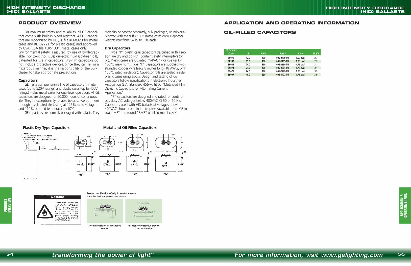
5-5
HIGH INTENSITY DISCHARGE(HID) BALLASTS
For more information, visit www.gelighting.com
HIGH INTENSITY DISCHARGE(HID) BALLASTS
5-4 transforming the power of light™
PRODUCT OVERVIEW APPLICATION AND OPERATING INFORMATION
OIL–FILLED CAPACITORS
Normal Position of ProtectiveDevice
Protective Device (Only in metal cases)Protective device to prevent case rupture
Barrier
Position of Protective Device After Activation
Barrier
Normal Cover Position
1/2"
Plastic Dry Type Capacitors Metal and Oil Filled Capacitors
For maximum safety and reliability, all GE capaci-tors come with built-in bleed resistors. All GE capaci-tors are recognized by UL (UL file #E68320 for metalcases and #E182721 for plastic cases) and approvedby CSA (CSA file #LR51331, metal cases only).Environmental safety is assured by use of biodegrad-able, nontoxic (no PCBs) dielectric fluid (soybean oil),patented for use in capacitors. Dry-film capacitors donot include protective devices. Since they can fail in ahazardous manner, it is the responsibility of the pur-chaser to take appropriate precautions.
CapacitorsGE has a comprehensive line of capacitors in metal
cases (up to 520V ratings) and plastic cases (up to 400Vratings) – plus metal cases for dual-level operation. All GEcapacitors are designed for 60,000 hours of continuouslife. They're exceptionally reliable because we put themthrough accelerated life testing at 125% rated voltageand 110% of rated temperature +10°C.
GE capacitors are normally packaged with ballasts. They
may also be ordered separately, bulk packaged, or individual-ly boxed with the suffix “BH” (metal cases only). Capacitorweights vary from 1/4 lb. to 1 lb. each.
Dry CapacitorsType “P” plastic case capacitors described in this sec-
tion are dry and do NOT contain safety interrupters (oroil). Plastic cases are UL rated “94V-O” (for use up to100°C maximum). Type "P" capacitors are supplied withstranded copper wire leads 8 inches long (18 AWG, with150°C rated insulation). Capacitor rolls are sealed insideplastic cases using epoxy. Design and testing of GEcapacitors follow specifications in Electronic IndustriesAssociation (EIA) Standard 456-A, titled “Metalized FilmDielectric Capacitors for Alternating CurrentApplication.”
“P” capacitors are designed and rated for continu-ous duty AC voltages below 400VAC @ 50 or 60 Hz.Capacitors used with HID ballasts at voltages above400VAC should contain interrupters (available from GE inoval “MF” and round “RMF” oil-filled metal cases).
GE ProductCode uF VACr Part # Case Ht (")
89078 12.0 400 005-2799-MF 1.50 oval 2.788982 15.0 400 005-1185-MF 1.75 oval 2.789083 24.0 360 005-3160-MF 1.75 oval 3.189071 24.0 400 005-2664-MF 1.75 oval 3.189077 24.0 480 005-2779-MF 1.75 oval 3.989007 48.0 330 005-1422-MF 1.75 oval 3.9
PROD
UCT
OVER
VIEW
APPL
ICAT
ION
&
OPER
ATIN
G IN
FO.

1.81"1.30"
0.58"
0.93"
0.43"
.29"
0.25" Dia.2 Holes
0.09"5.50"
0.93"
0.29"
0.90"
1.75"
45º
5-7
HIGH INTENSITY DISCHARGE(HID) BALLASTS
For more information, visit www.gelighting.com
HIGH INTENSITY DISCHARGE(HID) BALLASTS
BRAC
KET
REFE
REN
CE
5-6 transforming the power of light™
BRACKET REFERENCE CHART APPLICATION AND OPERATING INFORMATION
CORE & COIL WELDED BRACKETS
All welded brackets are .093" thick.
Ref. Drawing B1
0.75"0.25"
4.00"
3.35" 0.30"
0.75"0.25"
4.00"
3.35" 0.30"
1.00"1.25"
5.25"
4.60"
.250 Slot2 Places
1.25"
7.75"
7.75"
.281 Slot2 Places
1.75"on center
2.75"
7.75"
6.75"on center
0.50"
0.50"TYP.
6.10"on center
.281 Slot6 Req.
R. TYP.
Ref. Drawing B2
Ref. Drawing B1-A
1.00" 0.25"
5.25"
4.60"
Ref. Drawing B1-B
Ref. Drawing B3
Ref. Drawing B4
CORE & COIL ADJUSTABLEMOUNTINGBRACKETSRoutinely supplied with replacement kits. All welded brackets are .093" thick.
For use with:• 50 to 175 watt Mercury, High Pressure Sodium
and Metal Halide and some 250 watt Metal Halide
For use with:• 250 to 1500 watt Metal Halide• 250 to 1000 watt High Pressure Sodium and
Mercury Vapor
7.25"
1.300"
.090"
.580" .930"
.735".290"
1/4" Dia.2 Holes
.290"
45°
1.880"
2.685" 1.750"
.835"
.460"
Ref. Drawing ADJ2
Ref. Drawing MB1
Ref. Drawing MB2
APPL
ICAT
ION
&
OPER
ATIN
G IN
FO.
Underwriters Laboratories, Inc. AcceptanceAll F-Can and weatherproof ballasts listed in this
catalog are Underwriters Laboratories, Inc. whitecard listed, except those for 347 Volt operation. Allcore & coil, potted core & coil and postline ballastslisted in this catalog are Underwriters Laboratories,Inc. yellow card listed (component recognized).
Ballast ReplacementBallast replacement presents the possibility of
exposure to potentially hazardous voltages andshould be performed only by qualified personnel. Allinstallation, inspection and maintenance should beperformed only with the entire circuit power to fix-ture or equipment turned off. Installation shall be inaccordance with National Electric Code.
HeatA ballast, like any other electrical device, gener-
ates heat during normal operation. Planning formaximum heat dissipation with proper fixturedesign, installation planning and ballast selection willminimize the possibility of a heat-related problemarising. Excessive temperature will have an adverseeffect on ballast life.
Normal Temperature Limits:• F-Can Ballasts
Maximum case temperature: 90°C
• Weatherproof BallastsMaximum case temperature: 90°C
• Core & Coil Ballasts and Potted Core and Coil BallastsInsulation: Class 180°CMaximum coil temperature: 165°C(measured by change of resistance method)
All F-Can ballasts listed in this catalog areequipped with built-in automatic resetting internalthermal protection as a standard feature.
Other ballast types may be available with ther-mal protection as an option. If required, consult yourGE representative for availability and ordering infor-mation.
Whenever a ballast with thermal protection isused, it is imperative that the fixture/ballast/lampcombination be heat tested under actual or simulat-ed installation conditions to assure that the ballastwill not cycle.
The resetting thermal protector functions as athermostat which will open and temporarily deacti-vate the ballast when it exceeds the permissible tem-perature. The ballast will continue to cycle until thecause of overheating is eliminated. If the ballast isdefective, it must be replaced. If the cause is exter-nal, the ballast will resume normal operation afterabnormal conditions are eliminated.
To attain normal ballast life, the maximum coiltemperature of the ballast should not exceed the rat-ing of the insulation system. A temperature increaseof 10°C results in a 50% reduction of ballast life.
Low Ambient Temperature (Cold)As temperatures drop, less and less vaporized
gas is available within the arc tube of a high intensitydischarge lamp, thereby causing an increase in theopen circuit voltage required to initiate an arc in thelamp, until a point is reached where the lamp cannotbe started. The minimum temperature at which anyballast listed in this catalog will provide reliable start-ing is listed with the electrical characteristics.
Low ambient temperatures will also result in aslight increase in the warm-up period of any type ofhigh intensity discharge lamp.
Ballasts should be protected from weather, mois-ture, or other abnormal atmospheric conditions,unless specifically designed for use under adverseconditions.
FusingThe purpose of fusing an HID ballast is to
remove the ballast from the power line in the eventof a ballast system failure. A fuse does not protectthe ballast from failing.
Because the temperature in the ballastcompartment is high, typically 90OC, fuse ratings arespecified at 25OC, and that this rating declines as thetemperature increases, HID fuse recommendationsare made between 2 and 3 times the maximumcurrent the ballast will draw during all normalconditions.
Fast-blow fuses should not be used due to thepossibility of high inrush currents. These currents aredue to the fact that the power can be applied at anypoint in the AC voltage waveform. Standard andslow-blow are acceptable.
When using the 120V tap for auxiliary lighting, aslow-blow fuse should be used to protect the ballastfrom damage from a fault in the auxiliary lightingcircuit.
Ref. Drawing ADJ1

5-9
HIGH INTENSITY DISCHARGE(HID) BALLASTS
For more information, visit www.gelighting.com
HIGH INTENSITY DISCHARGE(HID) BALLASTS
5-8 transforming the power of light™
APPLICATION AND OPERATING INFORMATION
APPL
ICAT
ION
&
OPER
ATIN
G IN
FO.
SoundHigh intensity discharge lamp ballasts, like all
electromagnetic devices, produce noise, or “hum.” Itis the degree of noise which determines the exis-tence of a problem. Ballast noise will only be notice-able when it exceeds the ambient sound level of theinstallation. It is obvious that a ballast designed pri-marily for outdoor or factory use would not be suit-able in an office environment.
The vast improvements in all high intensity dis-charge lamps and ballasts, and their excellentenergy efficiency, have made them viable optionsfor many indoor applications. The ballasts beingconsidered should be carefully analyzed to ensurethat there will not be an objectionable level of bal-last noise.
All F-Can ballasts listed in this catalog are“Sound Rated” to aid in the selection of a ballastthat is proper for the environment in which it willoperate.
Potted core & coil ballasts are also designed tooperate at reduced sound levels, generally severaldecibels lower than a standard core & coil ballast.Core & coil ballasts are not sound rated.
In situations where light output necessitatesusing a ballast with a sound rating or noise levelnot normally acceptable, the ballast should beremotely mounted. Note, however, that not all bal-lasts listed in this catalog are designed or recom-mended for remote mounting.
PolarityPolarity refers to the proper connection of bal-
last lead wires to line wires. To aid you in making acorrect installation, GE ballast leads are color-codedfor easy identification. The white or yellow ballastlead is to be connected to the neutral or common.Choose the appropriate ballast voltage lead to con-nect to the line.
GroundingBallast and capacitors or starters in metallic
casings must always be grounded. Ballasts andcomponents may be grounded to the fixture orotherwise grounded. It would be hazardous tomake contact with an ungrounded fixture, ballastor other electrical component while in operation.
Operating Line Voltage LimitsTo receive the full benefits of rated lamp out-
put and to prolong ballast life, it is essential thatvoltage supplied to an installation be maintainedwithin the prescribed limits.
In general, the line voltage supplied to a lagtype ballast (reactor or high reactance autotrans-former) should be maintained within 5% of thevoltage for which the ballast is rated. The line volt-age to lead type ballasts (constant wattage auto-transformer or constant wattage isolated) shouldbe maintained within 10%.
Subjecting a ballast to excessive voltage for anextended period of time results in the deteriorationof the coil insulation. This insulation breakdownwill cause early ballast failure.
Low voltage has no damaging effect on theballast. It could, however, have an adverse effecton lamp performance and starting dependability.
MaintenanceSelecting and installing an adequate and
efficient lighting system means nothing if it isnot properly maintained. Maintenance mustalways be considered as part of the life cyclecost of any high intensity discharge lightinginstallation in order to assure the continued per-formance of the system as originally specified.
First and foremost in importance is properlamp maintenance. High intensity dischargelamps do not “burn out” like an incandescentbulb, but rather, undergo changes with the arctube which prevent the lamp from starting prop-erly, warming up and producing full light output.The beginning of difficulties such as these gener-ally indicates the end of a lamp's useful life. Also,a dead lamp left in a fixture can be very damag-ing to the ignitor in systems which utilize them.To overcome this problem, GE offers automaticshutoff ignitors, which are described in the igni-tor section of this catalog.
In difficult locations, group replacement of allthe lamps, working or not, is often more economi-cal and convenient than spot replacement. Thesame, of course, applies to ballasts which mightbe approaching the end of their life. Only you candecide what is right for your lighting system, butwhat is important is that you have a maintenanceprogram.
APPLICATION AND OPERATING INFORMATION
APPL
ICAT
ION
&
OPER
ATIN
G IN
FO.
Periodic cleaning of the fixtures‘ lenses andreflectors is also important in maintaining properlight output. For indoor systems, maintenance ofreflective surfaces, such as walls and ceilings, willalso help assure proper levels of illumination.
Standby Lighting and PackagingStandby Lighting
To provide light during a high intensity dischargelamp's warm-up period, or the cool-down period following a power interruption which has extin-guished it, incandescent standby lighting can beincorporated. This is accomplished by use of astandby lighting device, or remote, that switches offan incandescent lamp incorporated into the fixtureonce an arc has been established, or reestablished,in the HID lamp. Generally, standby lighting devicesoperate on 120 Volts, so a tap must be provided onballasts designed to operate at higher line voltages.
The 120 Volt terminal or lead on all GE dual-,tri- and multi-voltage ballasts can be used as a tapfor standby lighting when the ballast is utilized forany of the higher voltages. Many single voltage bal-lasts are available with a 120 Volt tap and are listedthroughout the core & coil data section. Other sin-gle voltage ballasts may be available in this version.Consult your GE representative for availability andprice information.
Any connection to the 120 Volt tap must beaccomplished by means of a slow-blow fuse. Thisfuse will protect the ballast from abnormal condi-tions in the standby lamp circuit or its controldevice. The fuse should be located in the coolestplace in the fixture (below 80°C). The recommend-ed fuse amperage and maximum auxiliary lampwattage are listed in this catalog for each ballastsuitable for standby lighting applications.
Be sure to follow the wiring instructions of thestandby lighting device manufacturer. All applicablerequirements of the National Electrical Code must be met.
Packaging
Standard PackGE high intensity discharge lamp ballasts are
routinely packed in easy-to-handle cartons contain-ing from 1 to 20 units per carton, depending on thesize and weight of the ballasts. Consult your GErepresentative regarding the number of “units percarton” for shipment with attached mountingbrackets, capacitors (for high power factor units),and ignitors (if required). Other ordering criteria maycause packaging to vary.
Individual CartonsAll distributor replacement kits, weatherproof,
postline, potted core & coil, and many larger bal-lasts are packaged in individual cartons.
Individual cartons serve a threefold purpose: asa display carton, a stock package, and a shipping container for the retail market. Individual cartonsmay be packed in master cartons, depending onweight and size.
Individual carton packaging may be available forother ballasts. Contact your GE representativeregarding availability and cost.

5-11
HIGH INTENSITY DISCHARGE(HID) BALLASTS
SPEC
IFIC
ATIO
NS
For more information, visit www.gelighting.com
HIGH INTENSITY DISCHARGE(HID) BALLASTS
NOM
ENCL
ATUR
E
5-10 transforming the power of light™
NOMENCLATURE TYPICAL SPECIFICATIONS FOR HID BALLASTS
ABBREVIATIONS
CWA Constant Wattage Autotransformer
CWI Constant Wattage Isolated
ISO Regulated Lag
R-HPF Reactor—High Power Factor
R-NPF Reactor—Normal Power Factor
HX-HPF Lag Type — High Reactance Autotransformer—High Power Factor
HX-NPF Lag Type — High Reactance Autotransformer—Normal PowerFactor
UL Bench Top Rise Temperature Code
To facilitate UL inspection, the UL Bench TopRise Temperature Code is shown on the core &coil ballast label as 1029X. 1029 is the ULStandard for HID Ballasts, and the X is thetemperature code. If a fixture is UL listed for1029D, then automatically all ballasts with anA, B, C or D temperature classification areacceptable for use within that same fixture.
UL Bench Top Rise Letter Code Temperature Range forClass H (180°C) Ballasts
A <75°C B 75°C<80°CC 80°C<85°C D 85°C<90°CE 90°C<95°C F 95°C<100°C
1 2 3 4 5 6 7 8 9Number of Digits
1 2 to 4 3 1 1 1 1 3 1M 2 0 0 0 M L T A C 5 M 0 0 0 C
Field Description
1 (M) Metal Halide, (P) Pulse Start Metal Halide, (S) High Pressure Sodium, (H) Mercury
2 35 to 2000 Watts (Varies from two to four digits)
3 (MLT) Quad, (ML5) Multi-5, (TRI) TriVolt, (48T) 480/120, (120) 120, (277) 277, (230) 230V/50Hz
4 (R) Reactor, (A) CWA, (I) CWI, (O) IsoReg, (L) High Reactance/Lag, (M) MagLag
5 (C), C&C, (F) F-Can, (W) Weatherproof, (E) Encased/Potted C&C (I) Indoor Encased
6 (E) E&I, (3) 3x4, (4) 4-3/4, (5) 5-3/4, (X) Non Core and Coil
7 (M) Mogul or Medium, (D) Double Ended, (X) Multiple Lamps, (L) Low Loss
8 Pack Code (000 to 999, per pack code listing)
9 (C) Carton, (T) Tray, (I) Individual, (K) Kit
Field
Lamp Type
(M/P/S/H)
Wattage
Primary Voltage
(MLT/M
L5/TRI/48T/120/277/
230)
Circuit Type(R/A
/I/O/L/M
)
Style(C/F/W
/E/I/P)
Frame Size
(E/3/4/5/X)
Socket Type &O
ther Oddities
(M/D
/X/L)
Pack Code(000 TO
999)
Container Type(C/T/I/K)
1. Ballasts shall be designed in accordance with allapplicable ANSI specifications including ANSIC82.4
2. The Core & Coil ballast shall be designed withclass "H" (180°C) or higher insulation systemand vacuum impregnated with a 100% solidsbased resin.
3. All coils shall be precision wound.4. Core & Coil ballasts shall be designed to oper-
ate at least 180 cycles of 12 hours on and 12hours off, with the lamp circuit in an open orshort-circuited condition and without unduereduction in ballast life.
5. Core & Coil ballast and starter combinationsshall be designed to provide a reliable lamp start-ing down to -40°C for High Pressure Sodiumand -30°C for Metal Halide at minimum ratedline voltage.
6. Manufacturer shall provide written warrantyagainst defects in workmanship, includingreplacement, for two years from date of man-ufacture.
Capacitors1. All capacitors will be provided with a self-con-
tained internal bleeder resistor.2. All oil-filled capacitors will be housed in corro-
sion-resistant steel cans and contain .25" quickdisconnect terminals.
3. All capacitors will be manufactured by ballastmanufacturer.
Ignitors1. All ignitors will be epoxy-filled with either a
plastic or aluminum external housing.2. The ignitor shall be so designed to provide six
months of lamp open circuit operation withoutfailure.
Kits1. All HID kits shall be precision wound to ensure
proper installation.2. All HID kits shall be pre-wired.3. All HID kits shall be built with color-coded
leads.4. All HID kits are to be UL and CSA recognized
following the guidelines found in UL 1029 andCAN/CSA-22.2 No.74-92 (part 2 and 3).
5. GE Model______________ (or approved equal).

5-13
HIGH INTENSITY DISCHARGE(HID) BALLASTS
DIST
RIBU
TOR
REPL
ACEM
ENT
KITS
For more information, visit www.gelighting.com
HIGH INTENSITY DISCHARGE(HID) BALLASTS
DIST
RIBU
TOR
REPL
ACEM
ENT
KITS
5-12 transforming the power of light™
DISTRIBUTOR REPLACEMENT KITS
GE's HID distributor replacement kits containthe appropriate core & coil, a properly rated capac-itor, and all other components required for ballastreplacement. Our kits are the quickest and easiestto install of any on the market, thanks to uniquedesign features like:
• Prewired capacitor and ignitor (if required) tosave time and reduce wiring errors
• Color coded leads to reduce risk of incorrectwiring inside the fixture
• Features that exceed UL standards, includingcapacitors that offer trip fault protection
• Simple installation instructions and trou-bleshooting tips
• UPS shippable box
Our kit offerings include many quad-voltage(120, 208, 240, or 277 volt) and 480 Volt core &coil ballasts, as well as the new Multi-5 five-volt-age ballast. 480 Volt ballasts are equipped with a120 Volt tap to accommodate standby lighting.
GE‘s Multi-5™ Ballast Lamp Replacement kit isavailable for metal halide and high pressure sodi-um applications. This easy to carry, convenient, all-in-one kit ensures ballast lamp compatibility.
Distributor replacement kit cartons are pack-aged in master cartons in quantities from 1 to 6units.
Master carton quantities can be found on GE'slist and distributor price sheets.
Quad, 480 Volt, Multi-5™ and Multi-5™ Uni-Pak™ Distributor Replacement Kits
Quad, 480 Volt, Multi-5™ and Multi-5™ Uni-Pak™ Distributor Replacement Kits
Lamp Type Wattage Voltage Frame Size GE Product Code Part NumberMetal 150 480-120 3 x 4 86711 M15048TLC3M500KHalide 175 Multi-5 3 x 4 87210 M175ML5AC3M500K
175 120/208/240/277 3 x 4 86741 M175MLTAC3M500K250 Multi-5 3 x 4 87211 M250ML5AC3M500K250 120/208/240/277 3 x 4 86765 M250MLTAC3M500K250 Multi-5 4.25 x 4.75 87212 M250ML5AC4M500K250 Multi-5™ Uni-Pak™ 3 x 4 49763 M250ML5AC3M555K250 Multi-5™ Uni-Pak™ 4.25 x 4.75 49742 M250ML5AC4M555K400 Multi-5 4.25 x 4.75 86808 M400ML5AC4M500K400 120/208/240/277 4.25 x 4.75 86814 M400MLTAC4M500K400 480-120 4.25 x 4.75 86803 M40048TAC4M500K400 Multi-5™ Uni-Pak™ 4.25 x 4.75 49745 M400ML5AC4M555K1000 Multi-5 4.25 x 5.75 87213 M1000ML5AC5M500K1000 120/208/240/277 4.25 x 5.75 86655 M1000MLTAC5M500K1000 480-120 4.25 x 5.75 86650 M100048TAC5M500K1500 120/208/240/277 4.25 x 5.75 86698 M1500MLTAC5M500K1500 480-120 4.25 x 5.75 86693 M150048TAC5M500K
Pulse 175 120/208/240/277 3 x 4 86885 P175MLTAC3M500KStart 175 480-120 3 x 4 86876 P17548TAC3M500KMetal 250 120/208/240/277 4.25 x 4.75 86935 P250MLTAC4M500KHalide 250 480-120 4.25 x 4.75 86926 P25048TAC4M500K
320 120/208/240/277 4.25 x 4.75 86959 P320MLTAC4M500K320 480-120 4.25 x 4.75 86952 P32048TAC4M500K350 120/208/240/277 4.25 x 4.75 86984 P350MLTAC4M500K
Lamp Type Wattage Voltage Frame Size GE Product Code Part Number400 120/208/240/277 4.25 x 4.75 87008 P400MLTAC4M500K400 480-120 4.25 x 4.75 86999 P40048TAC4M500K750 480-120 4.25 x 5.75 46936 P75048TAC5M500K
HPS 50 120/208/240/277 3 x 4 87152 S50MLTLC3M500K70 120/208/240/277 3 x 4 86587 S70MLTLC3M500K70 480-120 3 x 4 86456 S7048TLC3M500K100 120/208/240/277 3 x 4 87074 S100MLTLC3M500K100 480-120 3 x 4 87068 S10048TLC3M500K150 120/208/240/277 3 x 4 87094 S150MLTLC3M500K150 480-120 3 x 4 87087 S15048TLC3M500K250 Multi-5 4.25 x 4.75 87214 S250ML5AC4M500K250 120/208/240/277 4.25 x 4.75 87121 S250MLTAC4M500K250 Multi-5™ Uni-Pak™ 4.25 x 4.75 49757 S250ML5AC4M555K
400 Multi-5 4.25 x 4.75 8725 S400ML5AC4M500K
400 120/208/240/277 4.25 x 4.75 87164 S400MLTAC4M500K
400 480-120 4.25 x 4.75 87198 S40048TAC4M500K
400 Multi-5 4.25 x 5.75 87217 S400ML5AC5M500K
400 120/208/240/277 4.25 x 5.75 87175 S400MLTAC5M500K
400 480-120 4.25 x 5.75 87206 S40048TAC5M500K
400 Multi-5™ Uni-Pak™ 4.25 x 4.75 49758 S400ML5AC4M555K
1000 Multi-5 4.25 x 5.75 87218 S1000ML5AC5M500K
1000 120/208/240/277 4.25 x 5.75 87056 S1000MLTAC5M500K
1000 480-120 4.25 x 5.75 87048 S100048TAC5M500K
Mercury 100 120/208/240/277 3 x 4 86519 H100MLTAC3M500K
175 120/208/240/277 3 x 4 86527 H175MLTAC3M500K
400 120/208/240/277 4.25 x 4.75 86542 H400MLTAC4M500K

5-15
HIGH INTENSITY DISCHARGE(HID) BALLASTS
MH
150-
175
WAT
TS
For more information, visit www.gelighting.com
HIGH INTENSITY DISCHARGE(HID) BALLASTS
5-14 transforming the power of light™
MH
35-1
00 W
ATTS
MH 35/39 WATTS
CORE & COIL ELECTRONIC BALLASTSMETAL HALIDE LAMPS
Nom Dimensions Capacitor IgnitorGE Max Open Total Max UL
Product Input Catalog* Circuit Watts Input Circuit Fuse Wir Ref Min Dry Film Oil Filled Wt Catalog Distance BenchCode Volts Number Type Input Current Voltage Rating Dia Dwg A B Mfd Volt Dia Ht Oval Ht (lbs.) Number to lamp (ft) Top Rise
(1) 35/39 WATT M130 METAL HALIDE LAMP120 or 1.16 3208 or 0.67 3
86824240 or
M50MLTLC3M500K HX-HPF 670.57 2
4 PC1 1.0 2.6 6 280 1.2 2.2 1.31x2.16 2.2 4.3 MH100-3A 10 A
277 0.50 2
DIMENSIONS
DESCRIPTION SUFFIX *
For Ballast Only 000For Bracket Only (see pg. 5-6) 200For Capacitor Only (see pg. 5-6) 500For Distributor Replacement Kit (see pg. 5-12 thru 5-13) 500K BRef. Dwg. L W M S
1 4.00" 0.75" 3.35" 0.25"PC1 5.25" 1.25" 4.60" 0.25"
ML
W SBracket
See pg. 5-6 for adjustable mounting brackets anddetailed bracket drawings.
BMAX
0.250 Dia Thru2 Holes
0.199 Dia Thru4 Holes
A
2.438˝
2.812˝
3.500˝ 3.938˝
REFERENCE DRAWING PC1
MH 70 WATTSNom Dimensions Capacitor Ignitor
GE Max Open Total Max ULProduct Input Catalog* Circuit Watts Input Circuit Fuse Wir Ref Min Dry Film Oil Filled Wt Catalog Distance Bench
Code Volts Number Type Input Current Voltage Rating Dia Dwg A B Mfd Volt Dia Ht Oval Ht (lbs.) Number to lamp (ft) Top Rise(1) 70 WATT M98 METAL HALIDE LAMP – Medium Base
120 or 1.70 4 A
86847208 or
M70MLTLC3M500K HX-HPF 951.04
2453
4 PC1 1.3 2.9 8 280 1.2 2.7 1.31x2.16 2.2 4.3 MH100-3A 10B
240 or 0.87 3 B277 0.78 2 B
86839 480-120 M7048TLC3M HX-HPF 95 0.50 245 1 6 PC1 1.3 2.9 8 300 1.2 2.7 1.31x2.16 2.2 4.3 MH100-3A 10 E
MH 100 WATTS
Nom Dimensions Capacitor Ignitor ULGE Max Open Total Max Bench
Product Input Catalog* Circuit Watts Input Circuit Fuse Wir Ref Min Dry Film Oil Filled Wt Catalog Distance TopCode Volts Number Type Input Current Vltg Rtg Dia Dwg A B Mfd Volt Dia Ht Oval Ht (lbs.) Number to lamp (ft) Rise
(1) 100 WATT M90 OR M92 METAL HALIDE LAMP - Medium Base120 or 2.30 5
86675208 or
M100MLTLC3M500K HX-HPF 1301.30
2504
4 PC1 1.7 3.2 10 280 1.2 2.7 1.31x2.16 2.2 6.3 MH100-3A 10 A240 or 1.10 3
277 0.95 386667 480-120 M10048TLC3M500K HX-HPF 140 0.62 250 2 6 PC1 1.7 3.2 10 280 1.2 2.7 1.31x2.16 2.2 5.0 MH100-3A 10 C
CORE & COIL ELECTRONIC BALLASTSMETAL HALIDE LAMPS
DIMENSIONS
MH 150 WATTSNom Dimensions Capacitor Ignitor
GE Max Open Total Max ULProduct Input Catalog* Circuit Watts Input Circuit Fuse Wir Ref Min Dry Film Oil Filled Wt Catalog Distance Bench
Code Volts Number Type Input Current Vltg Rtg Dia Dwg A B Mfd Volt Dia Ht Oval Ht (lbs.) Number to lamp (ft) Top Rise(1) 150 WATT M102 METAL HALIDE LAMP - Medium Base
120 or 3.32 10
86718208 or
M150MLTLC3M500K HX-HPF 1851.93
2455
4 PC1 2.3 3.9 16 300 1.6 2.7 1.56x2.69 2.7 7.3 MH100-3A 10 D240 or 1.66 5
277 1.48 486711 480-120 M15048TLC3M500K HX-HPF 180 1.00 245 2 6 PC1 2.3 3.9 16 280 1.6 2.7 1.56x2.69 2.7 7.3 MH100-3A 10 F
BRef. Dwg. L W M S1 4.00” 0.75” 3.35” 0.25”
PC1 5.25” 1.25” 4.60” 0.25”
ML
W SBracket
See pg. 5-6 for adjustable mounting brackets anddetailed bracket drawings.
BMAX
0.250 Dia Thru2 Holes
0.199 Dia Thru4 Holes
A
2.438˝
2.812˝
3.500˝ 3.938˝
REFERENCE DRAWING PC1
MH 175 WATTS featuring Multi-5™
Nom Dimensions Capacitor IgnitorGE Max Open Total Max UL
Product Input Catalog* Circuit Watts Input Circuit Fuse Wir Ref Min Dry Film Oil Filled Wt Catalog Distance BenchCode Volts Number Type Input Current Voltage Rating Dia Dwg A B Mfd Volt Dia Ht Oval Ht (lbs.) Number to lamp (ft) Top Rise
(1) 175 WATT M57, M107 METAL HALIDE OR H39 MERCURY LAMPS 120 or 1.80 5 A
86741208 or
M175MLTAC3M500K CWA 2131.10
3103
21 PC1 2.2 3.6 10 400 1.6 2.7 1.56x2.69 2.7 6.8 n/a n/aB
240 or 0.90 3 A277 0.78 2 A
120 or 208 1.90 5208 or 208 1.10 3
87210 240 or M175ML5AC3M500K CWA 208 0.95 300 3 44 PC1 2.3 3.6 10 400 1.6 2.7 1.56x2.69 2.7 6.8 n/a n/a B277 or 208 0.85 2
480 210 0.50 1.5
DESCRIPTION SUFFIX *
For Ballast Only 000For Bracket Only (see pg. 5-6) 200For Capacitor Only (see pg. 5-6) 500For Distributor Replacement Kit (see pg. 5-12 thru 5-13) 500K

5-17
HIGH INTENSITY DISCHARGE(HID) BALLASTS
For more information, visit www.gelighting.com
HIGH INTENSITY DISCHARGE(HID) BALLASTS
5-16 transforming the power of light™
MH
250
WAT
TS
CORE & COIL ELECTRONIC BALLASTSMETAL HALIDE LAMPS
DIMENSIONS
BRef. Dwg. L W M S1 4.00” 0.75” 3.35” 0.25”
PC1 5.25” 1.25” 4.60” 0.25”PC 2 5.25” 1.25” 4.60” 0.25” M
L
W SBracket
See pg. 5-6 for adjustable mounting brackets anddetailed bracket drawings.
BMAX
0.250 Dia Thru2 Holes
0.199 Dia Thru4 Holes
A
2.438˝
2.812˝
3.500˝ 3.938˝
REFERENCE DRAWING PC1 REFERENCE DRAWING PC2
MH 250 WATTS featuring Multi-5™
Nom Dimensions Capacitor IgnitorGE Max Open Total Max UL
Product Input Catalog* Circuit Watts Input Circuit Fuse Wir Ref Min Dry Film Oil Filled Wt Catalog Distance BenchCode Volts Number Type Input Current Voltage Rating Dia Dwg A B Mfd Volt Dia Ht Oval Ht (lbs.) Number to lamp (ft) Top Rise
(1) 250 WATT M58 METAL HALIDE OR H37 MERCURY LAMP - 4" Frame120 or 2.60 8 C
86765208 or
M250MLTAC3M500K CWA 2941.58
2805
21 PC1 3.0 4.3 15 400 1.6 3.6 1.91x2.91 2.7 9.0 n/a n/aD
240 or 1.30 4 C277 1.12 3 C
120 or 2.60 8 B208 or 1.60 5 B
87211 240 or M250ML5AC3M500K CWA 280 1.30 290 4 44 PC1 3.0 4.3 15 400 1.6 3.6 1.91x2.91 2.7 9.0 n/a n/a B277 or 1.20 3 C
480 0.70 2 C
MH 250 WATTS featuring Multi-5™
Nom Dimensions Capacitor IgnitorGE Max Open Total Max UL
Product Input Catalog* Circuit Watts Input Circuit Fuse Wir Ref Min Dry Film Oil Filled Wt Catalog Distance BenchCode Volts Number Type Input Current Voltage Rating Dia Dwg A B Mfd Volt Dia Ht Oval Ht (lbs.) Number to lamp (ft) Top Rise
(1) 250 WATT M58 METAL HALIDE OR H37 MERCURY LAMPS - 4.75" Frame120 or 2.50 8208 or 1.40 5
87212 240 or M250ML5AC4M500K CWA 293 1.30 305 4 44 PC2 1.8 3.6 15 400 1.6 3.6 1.91x2.91 2.7 10.8 n/a n/a A277 or 1.10 3
480 0.65 2
BMAX
0.250 Dia Thru2 Holes
0.250 Dia Thru4 Holes
A
3.875˝
4.250˝
4.375˝ 4.750˝
MH
400-
1000
WAT
TS
CORE & COIL ELECTRONIC BALLASTSMETAL HALIDE LAMPS
MH 400 WATTS featuring Multi-5™
Nom Dimensions Capacitor IgnitorGE Max Open Total Max UL
Product Input Catalog* Circuit Watts Input Circuit Fuse Wir Ref Min Dry Film Oil Filled Wt Catalog Distance BenchCode Volts Number Type Input Current VoltageRating Dia Dwg A B Mfd Volt Dia Ht Oval Ht (lbs.) Number to lamp (ft) Top Rise(1) 400 WATT M59 METAL HALIDE OR H33 MERCURY LAMP
86803 480-120 M40048TAC4M500K CWA 458 1.00 300 5 19 PC2 2.0 3.9 24 400 1.8 3.6 1.91x2.91 3.1 11.2 n/a n/a E120 or 4.00 10 C
86814208 or
M400MLTAC4M500K CWA 4582.30
3008
21 PC2 2.0 3.9 24 360 1.8 3.6 1.91x2.91 3.1 11.2 n/a n/aD
240 or 2.00 5 D277 1.70 5 E
120 or 4.00 10 E208 or 2.30 8 D
87212 240 or M400ML5AC4M500K CWA 458 2.00 300 5 44 PC2 2.0 3.9 24 400 1.8 3.6 1.91x2.91 3.1 11.2 n/a n/a E277 or 1.70 5 D
480 1.00 5 E
DIMENSIONS
BRef. Dwg. L W M SPC 2 5.25” 1.25” 4.60” 0.25”PC3 7.75” 2.75” 6.10” 0.25”
ML
W SBracket
REFERENCE DRAWING PC2 REFERENCE DRAWING PC3
BMAX
0.250 Dia Thru2 Holes
0.250 Dia Thru4 Holes
A
3.875˝
4.250˝
4.375˝ 4.750˝
BMAX
0.250 Dia Thru2 Holes
0.250 Dia Thru8 Holes
A
3.875˝4.250˝ 4.375˝
5.375˝ 5.750˝
Nom Dimensions Capacitor IgnitorGE Max Open Total Max UL
Product Input Catalog* Circuit Watts Input Circuit Fuse Wir Ref Min Dry Film Oil Filled Wt Catalog Distance BenchCode Volts Number Type Input Current Voltage Rating Dia Dwg A B Mfd Volt Dia Ht Oval Ht (lbs.) Number to lamp (ft) Top Rise(1) 1000 WATT M47 METAL HALIDE OR H36 MERCURY LAMP86650 480-120 M100048TAC5M500K CWA 1080 2.30 420 10 19 PC3 2.8 4.6 24 480 n/a n/a 1.91x2.91 3.9 22.0 n/a n/a C
120 or 9.20 20
86655208 or
M1000MLTAC5M500K CWA 10805.30
42015
21 PC3 2.8 4.7 24 480 n/a n/a 1.91x2.91 3.9 22.0 n/a n/a D240 or 4.60 10
277 4.00 10120 or 9.00 20 F208 or 5.20 15 B
87213 240 or M1000ML5AC5M500K CWA 1080 4.40 425 10 44 PC3 2.8 4.6 24 480 n/a n/a 1.91x2.91 3.9 22.0 n/a n/a B277 or 3.90 10 B
480 2.30 10 B
MH 1000 WATTS featuring Multi-5™
See pg. 5-6 for adjustable mounting brackets anddetailed bracket drawings.
DESCRIPTION SUFFIX *
For Ballast Only 000For Bracket Only (see pg. 5-6) 200For Capacitor Only (see pg. 5-6) 500For Distributor Replacement Kit (see pg. 5-12 thru 5-13) 500K
DESCRIPTION SUFFIX *
For Ballast Only 000For Bracket Only (see pg. 5-6) 200For Capacitor Only (see pg. 5-6) 500For Distributor Replacement Kit (see pg. 5-12 thru 5-13) 500K

5-19
HIGH INTENSITY DISCHARGE(HID) BALLASTS
For more information, visit www.gelighting.com
HIGH INTENSITY DISCHARGE(HID) BALLASTS
5-18 transforming the power of light™
MH
1500
WAT
TS
PULS
E ST
ART
MH
175-
320
WAT
TS
CORE & COIL ELECTRONIC BALLASTSMETAL HALIDE LAMPS
MH 1500 WATTS
DIMENSIONS
BRef. Dwg. L W M SPC3 7.75” 2.75” 6.10” 0.25”
ML
W SBracket
REFERENCE DRAWING PC3
BMAX
0.250 Dia Thru2 Holes
0.250 Dia Thru8 Holes
A
3.875˝4.250˝ 4.375˝
5.375˝ 5.750˝
Nom Dimensions Capacitor IgnitorGE Max Open Total Max UL
Product Input Catalog* Circuit Watts Input Circuit Fuse Wir Ref Min Dry Film Oil Filled Wt Catalog Distance BenchCode Volts Number Type Input Current Voltage Rating Dia Dwg A B Mfd Volt Dia Ht Oval Ht (lbs.) Number to lamp (ft) Top Rise
(1) 1500 WATT M48 METAL HALIDE LAMP86693 480-120 M150048TAC5M500K CWA 1610 3.50 450 10 19 PC3 4.3 6.4 32 525 n/a n/a 1.97x3.66 3.9 29.5 n/a n/a E
120 or 14.00 40 F86698 208 or M1500MLTAC5M500K CWA 1610 8.00 450 25 21 PC3 4.3 6.4 32 525 n/a n/a 1.97x3.66 3.9 30.0 n/a n/a E
277 7.00 20 F
See pg. 5-6 for adjustable mounting brackets anddetailed bracket drawings.
CORE & COIL ELECTRONIC BALLASTSMETAL HALIDE LAMPS
PULSE START MH 250-320 WATTS
DIMENSIONS
BRef. Dwg. L W M SPC1 5.25” 1.25” 4.60” 0.25”PC 2 5.25” 1.25” 4.60” 0.25”
ML
W SBracket
Nom Dimensions Capacitor IgnitorGE Max Open Total Max UL
Product Input Catalog* Circuit Watts Input Circuit Fuse Wir Ref Min Dry Film Oil Filled Wt Catalog Distance BenchCode Volts Number Type Input Current Voltage Rating Dia Dwg A B Mfd Volt Dia Ht Oval Ht (lbs.) Number to lamp (ft) Top Rise
(1) 250/320 WATT M138 OR M132METAL HALIDE PULSE START LAMP 120 or 2.40 8
86935208 or
P250MLTAC4M500K CWA 2851.45
2965
11 PC2 1.3 3.2 14 400 1.6 3.6 1.91x2.91 2.7 9.3 MH350-1 10 A240 or 1.20 5
277 1.06 386926 480-120 P25048TAC4M500K CWA 285 0.62 290 2 13 PC2 2.0 3.8 14.0 400 1.6 3.6 1.91x2.91 2.7 11.3 MH350-1 10 A
120 or 4.10 8
86959208 or
P320MLTAC4M500K CWA 3652.50
2927
11 PC2 2.0 3.8 20.5 400 1.8 3.6 1.91x2.91 3.1 11.2 MH350-1 10 A240 or 2.00 5
277 1.85 5120 or 3.25 8
86968 277 or P320TRIAC4M500K CWA 365 1.40 265 4 15 PC2 1.7 3.7 24.5 300 1.6 3.6 1.91x2.91 2.7 11.0 MH350-1 10 A340 1.15 3
86952 480-120 P32048TAC4M500K CWA 405 1.06 292 3 13 PC2 2.0 3.8 20.5 400 1.8 3.6 1.91x2.91 3.1 11.3 MH350-1 10 A
REFERENCE DRAWING PC1
BMAX
0.250 Dia Thru2 Holes
0.199 Dia Thru4 Holes
A
2.438˝
2.812˝
3.500˝ 3.938˝
PULSE START MH 175 WATTS
Nom Dimensions Capacitor IgnitorGE Max Open Total Max UL
Product Input Catalog* Circuit Watts Input Circuit Fuse Wir Ref Min Dry Film Oil Filled Wt Catalog Distance BenchCode Volts Number Type Input Current Vltg Rtg Dia Dwg A B Mfd Volt Dia Ht Oval Ht (lbs.) Number to lamp (ft) Top Rise
(1) 175 WATT M137 METAL HALIDE PULSE START LAMP120 or 1.80 5 A
86885208 or
P175MLTAC3M500K CWA 2081.10
2553
11 PC1 2.1 3.6 10 400 1.6 2.7 1.31x2.16 3.9 6.8 MH350-1 10B
240 or 0.90 3 B277 0.78 2 B
86876 480-120 P17548TAC3M500K CWA 210 0.45 255 2 13 PC1 2.6 4.1 10 400 1.6 2.7 1.31x2.16 3.9 7.0 MH350-1 10 C
REFERENCE DRAWING PC2
BMAX
0.250 Dia Thru2 Holes
0.250 Dia Thru4 Holes
A
3.875˝
4.250˝
4.375˝ 4.750˝
DESCRIPTION SUFFIX *
For Ballast Only 000For Bracket Only (see pg. 5-6) 200For Capacitor Only (see pg. 5-6) 500For Distributor Replacement Kit (see pg. 5-12 thru 5-13) 500K
DESCRIPTION SUFFIX *
For Ballast Only 000For Bracket Only (see pg. 5-6) 200For Capacitor Only (see pg. 5-6) 500For Distributor Replacement Kit (see pg. 5-12 thru 5-13) 500K

5-21
HIGH INTENSITY DISCHARGE(HID) BALLASTS
For more information, visit www.gelighting.com
HIGH INTENSITY DISCHARGE(HID) BALLASTS
5-20 transforming the power of light™
PULS
E ST
ART
MH
350-
400
WAT
TS
PULS
E ST
ART
MH
750
WAT
TS
CORE & COIL ELECTRONIC BALLASTSMETAL HALIDE LAMPS
DIMENSIONSREFERENCE DRAWING RX1
BRef. Dwg. L W M SPC 2 5.25” 1.25” 4.60” 0.25”RX1 4.00” 0.75” 3.35” 0.25”
ML
W SBracket
REFERENCE DRAWING PC2
BMAX
0.250 Dia Thru2 Holes
0.250 Dia Thru4 Holes
A
3.875˝
4.250˝
4.375˝ 4.750˝
PULSE START MH 350-400 WATTS
Nom Dimensions Capacitor IgnitorGE Max Open Total Max UL
Product Input Catalog* Circuit Watts Input Circuit Fuse Wir Ref Min Dry Film Oil Filled Wt Catalog Distance BenchCode Volts Number Type Input Current Vltg Rtng Dia Dwg A B Mfd Volt Dia Ht Oval Ht (lbs.) Number to lamp (ft) Top Rise
(1) 350 WATT M131 METAL HALIDE PULSE START LAMP120 or 4.10 10
86984208 or
P350MLTAC4M500K CWA 4002.50
2927
11 PC2 2.0 3.8 22 400 1.8 3.6 1.91x2.91 3.1 11.2 MH350-1 10 A240 or 2.00 5
277 1.85 5
42692 277 P350277RCEM500KRX-NPF
3773.80 277 8 1 RX1 1.5 3.2 22.5 280 — — — — 6.8 MH350-1 10 A
RX-HPF 2.34 1.6 3.6 1.56x2.69 3.5
(1) 400 WATT M135 METAL HALIDE PULSE START LAMP120 or 4.10 10
87008208 or
P400MLTAC4M500K CWA 4582.50
2927
11 PC2 2.0 3.8 24 400 1.8 3.6 1.91x2.91 3.1 11.2 MH350-1 10 D240 or 2.00 5
277 1.85 586999 480-120 P40048TAC4M500K CWA 458 1.06 292 3 13 PC2 2.0 3.8 24 400 1.8 3.6 1.19x2.91 3.1 11.3 MH350-1 10 D
CORE & COIL ELECTRONIC BALLASTSMETAL HALIDE LAMPS
PULSE START MH 750 WATTS
DIMENSIONS
BRef. Dwg. L W M SPC3 7.75” 2.75” 6.10” 0.25”
ML
W SBracket
REFERENCE DRAWING PC3
BMAX
0.250 Dia Thru2 Holes
0.250 Dia Thru8 Holes
A
3.875˝4.250˝ 4.375˝
5.375˝ 5.750˝
See pg. 5-6 for adjustable mounting brackets anddetailed bracket drawings.
Nom Dimensions Capacitor IgnitorGE Max Open Total Max UL
Product Input Catalog* Circuit Watts Input Circuit Fuse Wir Ref Min Dry Film Oil Filled Wt Catalog Distance BenchCode Volts Number Type Input Current Vltg Rtng Dia Dwg A B Mfd Volt Dia Ht Oval Ht (lbs.) Number to lamp (ft) Top Rise
(1) 750 WATT M149 METAL HALIDE PULSE START LAMP120 or 6.90 15
46934208 or
P750MLTAC5M500K CWA 8104.00
4008
11 PC3 2.8 4.6 24 480 n/a n/a 1.91x2.91 3.9 22.0 HPS750-1B 10 D240 or 3.50 8
277 3.00 846936 480-120 P75048TAC5M500K CWA 810 2.00 400 6 13 PC3 2.8 4.6 24 480 n/a n/a 1.91x2.91 3.9 22.0 HPS750-1B 10 E
DESCRIPTION SUFFIX *
For Ballast Only 000For Bracket Only (see pg. 5-6) 200For Capacitor Only (see pg. 5-6) 500For Distributor Replacement Kit (see pg. 5-12 thru 5-13) 500K
DESCRIPTION SUFFIX *
For Ballast Only 000For Bracket Only (see pg. 5-6) 200For Capacitor Only (see pg. 5-6) 500For Distributor Replacement Kit (see pg. 5-12 thru 5-13) 500K

5-23
HIGH INTENSITY DISCHARGE(HID) BALLASTS
For more information, visit www.gelighting.com
HIGH INTENSITY DISCHARGE(HID) BALLASTS
5-22 transforming the power of light™
HPS
50 W
ATTS
HPS
100-
150
WAT
TS
CORE & COIL ELECTRONIC BALLASTSHIGH PRESSURE SODIUM LAMPS
HPS 70 WATTS
DIMENSIONS
BRef. Dwg. L W M SPC1 5.25” 1.25” 4.60” 0.25”1, 1a 4.00” 0.75” 3.35” 0.25”
ML
W SBracket
REFERENCE DRAWING 1
.203" Dia Thru4 Holes
0.594"
0.438"
BA
2.188"1.750"
2.625"
2.188"
1.750"
.203" Dia Thru4 Holes
2.625"
2.188"
0.594"
0.438"0.438"
2.188"
A B
REFERENCE DRAWING PC1
BMAX
0.250 Dia Thru2 Holes
0.199 Dia Thru4 Holes
A
2.438˝
2.812˝
3.500˝ 3.938˝
See pg. 5-6 for adjustable mounting brackets anddetailed bracket drawings.
Nom Dimensions Capacitor IgnitorGE Max Open Total Max UL
Product Input Catalog* Circuit Watts Input Circuit Fuse Wir Ref Min Dry Film Oil Filled Wt Catalog Distance BenchCode Volts Number Type Input Current Vltg Rtng Dia Dwg A B Mfd Volt Dia Ht Oval Ht (lbs.) Number to lamp (ft) Top Rise
(1) 70 WATT S62 HIGH PRESSURE SODIUM lamp
86605 1201233-142U0001 R-NPF 83 2.10
1208 1 1 1.3 2.6 — — — — — — 2.3 HPS150-3A 3 A
1233-142W u R-HPF 1.30 5 1A 1a 1.3 2.7 28 120 1.6 2.7 n/a n/a 2.5 Permanently Attached
86456 480-120 S7048TLC3M500K HX-HPF 94 0.34 120 2 6 PC1 1.4 2.8 7 280 1.2 2.2 1.31x2.16 2.2 6.0 HPS150-3A 10 A120 or 1.40 5 A
86587208 or
S70MLTLC3M500K HX-HPF 940.83
1203
4 PC1 1.4 2.7 7 280 1.2 2.2 1.31x2.16 2.2 4.1 HPS150-3A 10B
240 or 0.72 3 B277 0.62 2 B
HPS 50 WATTS
Nom Dimensions Capacitor IgnitorGE Max Open Total Max UL
Product Input Catalog* Circuit Watts Input Circuit Fuse Wir Ref Min Dry Film Oil Filled Wt Catalog Distance BenchCode Volts Number Type Input Current Vltg Rtng Dia Dwg A B Mfd Volt Dia Ht Oval Ht (lbs.) Number to lamp (ft) Top Rise
(1) 50 WATT S68 HIGH PRESSURE SODIUM LAMP120 or 1.24 5
87152208 or
S50MLTLC3M500K HX-HPF 640.59
1203
4 PC1 1.4 2.6 5 280 1.2 2.2 1.31x2.16 2.2 4.1 HPS150-3A 10 A240 or 0.50 3
277 0.44 2
REFERENCE DRAWING 1a
CORE & COIL ELECTRONIC BALLASTSHIGH PRESSURE SODIUM LAMPS
HPS 150 WATTS
DIMENSIONS
BRef. Dwg. L W M SPC1 5.25” 1.25” 4.60” 0.25”1, 1a 4.00” 0.75” 3.35” 0.25”
ML
W SBracket
REFERENCE DRAWING 1
.203" Dia Thru4 Holes
0.594"
0.438"
BA
2.188"1.750"
2.625"
2.188"
REFERENCE DRAWING 1a
1.750"
.203" Dia Thru4 Holes
2.625"
2.188"
0.594"
0.438"0.438"
2.188"
A B
REFERENCE DRAWING PC1
BMAX
0.250 Dia Thru2 Holes
0.199 Dia Thru4 Holes
A
2.438˝
2.812˝
3.500˝ 3.938˝
See pg. 5-6 for adjustable mounting brackets anddetailed bracket drawings.
1 Also can be used on a 277 Volt line in conjunction with step-down transformers.
Nom Dimensions Capacitor IgnitorGE Max Open Total Max UL
Product Input Catalog* Circuit Watts Input Circuit Fuse Wir Ref Min Dry Film Oil Filled Wt Catalog Distance BenchCode Volts Number Type Input Current Vltg Rtng Dia Dwg A B Mfd Volt Dia Ht Oval Ht (lbs.) Number to lamp (ft) Top Rise
(1) 150 WATT S55 HIGH PRESSURE SODIUM LAMP
86606 120 11233-154U001 R-NPF
1714.40 120 15 1 1 2.0 3.0 — — — — — — 3.2 HPS150-3 3 A
1233-154W u R-HPF 3 2.40 8 1A 1a 2.0 3.4 52 240 1.8 3.6 2.12 2.9 3.5 Permanently Attached
87087 480-120 S15048TLC3M500K HX-HPF 189 0.72 120 3 4A PC1 3.0 4.5 14 280 1.6 2.7 1.56x2.69 2.7 8.7 HPS150-3A 10 D120 or 3.00 10 C
87094208 or
S150MLTLC3M500K HX-HPF 1891.65
1205
4 PC1 2.4 3.7 14 280 1.6 2.7 1.56x2.69 2.7 7.0 HPS150-3A 10C
240 or 1.45 5 B277 1.25 5 C
HPS 100 WATTSNom Dimensions Capacitor Ignitor
GE Max Open Total Max ULProduct Input Catalog* Circuit Watts Input Circuit Fuse Wir Ref Min Dry Film Oil Filled Wt Catalog Distance Bench
Code Volts Number Type Input Current Vltg Rtng Dia Dwg A B Mfd Volt Dia Ht Oval Ht (lbs.) Number to lamp (ft) Top Rise(1) 100 WATT S54 HIGH PRESSURE SODIUM LAMP87068 480-120 S10048TLC3M500K HX-HPF 135 0.57 122 2 6 PC1 2.0 3.3 10 280 1.2 2.7 1.31x2.16 2.7 6.5 HPS150-3A 10 B
120 or 2.20 8 B
87074208 or
S100MLTLC3M500K HX-HPF 1221.40
1205
4 PC1 2.0 3.3 10 280 1.2 2.7 1.31x2.16 2.7 5.9 HPS150-3A 10A
240 or 1.10 5 A277 0.95 3 A
DESCRIPTION SUFFIX *
For Ballast Only 000For Bracket Only (see pg. 5-6) 200For Capacitor Only (see pg. 5-6) 500For Distributor Replacement Kit (see pg. 5-12 thru 5-13) 500K
DESCRIPTION SUFFIX *
For Ballast Only 000For Bracket Only (see pg. 5-6) 200For Capacitor Only (see pg. 5-6) 500For Distributor Replacement Kit (see pg. 5-12 thru 5-13) 500K

5-25
HIGH INTENSITY DISCHARGE(HID) BALLASTS
For more information, visit www.gelighting.com
HIGH INTENSITY DISCHARGE(HID) BALLASTS
5-24 transforming the power of light™
HPS
250-
400
WAT
TS
HPS
400-
1000
WAT
TS
CORE & COIL ELECTRONIC BALLASTSHIGH PRESSURE SODIUM LAMPS
HPS 250 WATTS featuring Multi-5™
DIMENSIONS
BRef. Dwg. L W M SPC 2 5.25” 1.25” 4.60” 0.25”
ML
W SBracket
REFERENCE DRAWING PC2
BMAX
0.250 Dia Thru2 Holes
0.250 Dia Thru4 Holes
A
3.875˝
4.250˝
4.375˝ 4.750˝
See pg. 5-6 for adjustable mounting brackets anddetailed bracket drawings.
Nom Dimensions Capacitor IgnitorGE Max Open Total Max UL
Product Input Catalog* Circuit Watts Input Circuit Fuse Wir Ref Min Dry Film Oil Filled Wt Catalog Distance BenchCode Volts Number Type Input Current Voltage Rating Dia Dwg A B Mfd Volt Dia Ht Oval Ht (lbs.) Number to lamp (ft) Top Rise
(1) 250 WATT S50 HIGH PRESSURE SODIUM LAMP 120 or 2.50 8
87121208 or
S250MLTAC4M500K CWA 3001.50
1855 11 PC2 1.7 3.7 35 280 1.8 3.6 1.91x2.91 3.1 10.3 HPS400-3A 10 A
240 or 1.30 4277 1.10 4
120 or 2.50 8208 or 1.43 5
87214 240 or S250ML5AC4M500K CWA 300 1.25 200 4 46 PC2 2.0 3.8 35 280 1.8 3.6 1.91x2.91 3.1 10.3 HPS400-3 10 A277 or 1.10 4
480 0.65 4
HPS 400 WATTS featuring Multi-5™
Nom Dimensions Capacitor IgnitorGE Max Open Total Max UL
Product Input Catalog* Circuit Watts Input Circuit Fuse Wir Ref Min Dry Film Oil Filled Wt Catalog Distance BenchCode Volts Number Type Input Current Voltage Rtng Dia Dwg A B Mfd Volt Dia Ht Oval Ht (lbs.) Number to lamp (ft) Top Rise
(1) 400 WATT S51 HIGH PRESSURE SODIUM LAMP - 4 3/4” FRAME87198 480-120 S40048TAC4M500K CWA 465 1.00 190 5 13 PC2 2.3 4.1 55 240 1.8 3.6 1.91x2.91 3.5 14.5 HPS400-3A 10 D
120 or 3.90 15 D
87164208 or
S400MLTAC4M500K CWA 4652.25
1908
11 PC2 2.3 4.1 55 240 1.8 3.6 1.91x2.91 3.5 14.5 HPS400-3A 10D
240 or 1.95 8 C277 1.70 5 D
120 or 3.90 15 B208 or 2.25 8 D
87215 240 or S400ML5AC4M500K CWA 465 1.95 190 8 46 PC2 2.3 4.1 55 240 1.8 3.6 1.91x2.91 3.5 15.5 HPS400-3 10 C277 or 1.70 5 C
480 1.00 5 B
CORE & COIL ELECTRONIC BALLASTSHIGH PRESSURE SODIUM LAMPSHPS 400 WATTS featuring Multi-5™
DIMENSIONS
BRef. Dwg. L W M SPC3 7.75” 2.75” 6.10” 0.25”
ML
W SBracket
REFERENCE DRAWING PC3
BMAX
0.250 Dia Thru2 Holes
0.250 Dia Thru8 Holes
A
3.875˝4.250˝ 4.375˝
5.375˝ 5.750˝See pg. 5-6 for adjustable mounting brackets anddetailed bracket drawings.
Nom Dimensions Capacitor IgnitorGE Max Open Total Max UL
Product Input Catalog* Circuit Watts Input Circuit Fuse Wir Ref Min Dry Film Oil Filled Wt Catalog Distance BenchCode Volts Number Type Input Current Vltg Rtng Dia Dwg A B Mfd Volt Dia Ht Oval Ht (lbs.) Number to lamp (ft) Top Rise
(1) 400 WATT S51 HIGH PRESSURE SODIUM LAMP - 5 3/4" Frame87206 480-120 S40048TAC5M500K CWA 465 1.00 190 5 13 PC3 2.3 4.2 48 280 1.8 4.6 1.91x2.91 3.9 15.5 HPS400-3A 10 D
120 or 3.90 15
87175208 or
S400MLTAC5M500K CWA 4672.25
1958
11 PC3 2.3 4.1 48 280 1.8 4.6 1.91x2.91 3.9 15.5 HPS400-3A 10 D240 or 1.95 8
277 1.70 5120 or 3.90 15208 or 2.25 8
87217 240 or S400ML5AC5M500K CWA 468 1.95 1.95 8 46 PC3 2.5 4.3 48 280 1.8 4.6 1.91x2.91 3.9 15.5 HPS400-3 10 C277 or 1.70 5
480 1.00 5
HPS 1000 WATTS featuring Multi-5™
Nom Dimensions Capacitor IgnitorGE Max Open Total Max UL
Product Input Catalog* Circuit Watts Input Circuit Fuse Wir Ref Min Dry Film Oil Filled Wt Catalog Distance BenchCode Volts Number Type Input Current Vltg Rtng Dia Dwg A B Mfd Volt Dia Ht Oval Ht (lbs.) Number to lamp (ft) Top Rise
(1) 1000 WATT S52 HIGH PRESSURE SODIUM lamp87048 480-120 S100048TAC5M500K CWA 1100 2.40 440 8 13 PC3 3.8 6.0 26 525 n/a n/a 1.91x2.91 4.3 25.0 HPS1000-4B 15 D
120 or 9.50 20
87056208 or
S1000MLTAC5M500K CWA 11005.50
44015
11 PC3 3.8 5.6 26 525 n/a n/a 1.91x2.91 4.25 26.0 HPS1000-4B 15 C240 or 4.80 10
277 4.10 10120 or 9.10 20208 or 5.40 15
87218 240 or S1000ML5AC5M500K CWA 1.48 4.60 435 10 46 PC3 3.8 5.5 26 525 n/a n/a 1.91x2.91 4.25 26.0 HPS1000-4 15 D277 or 4.10 10
480 2.40 8
DESCRIPTION SUFFIX *
For Ballast Only 000For Bracket Only (see pg. 5-6) 200For Capacitor Only (see pg. 5-6) 500For Distributor Replacement Kit (see pg. 5-12 thru 5-13) 500K
DESCRIPTION SUFFIX *
For Ballast Only 000For Bracket Only (see pg. 5-6) 200For Capacitor Only (see pg. 5-6) 500For Distributor Replacement Kit (see pg. 5-12 thru 5-13) 500K

5-27
HIGH INTENSITY DISCHARGE(HID) BALLASTS
For more information, visit www.gelighting.com
HIGH INTENSITY DISCHARGE(HID) BALLASTS
5-26 transforming the power of light™
MER
CURY
100-
400
WAT
TS
MH
75-1
50 W
ATTS
CORE & COIL ELECTRONIC BALLASTSMERCURY LAMPS
MERCURY 100 WATTSNom Dimensions Capacitor Ignitor
GE Max Open Total Max ULProduct Input Catalog* Circuit Watts Input Circuit Fuse Wir Ref Min Dry Film Oil Filled Wt Catalog Distance Bench
Code Volts Number Type Input Current Vltg Rtng Dia Dwg A B Mfd Volt Dia Ht Oval Ht (lbs.) Number to lamp (ft) Top Rise(1) 100 WATT H38 or H44 MERCURY LAMP
120 or 1.05 3
86519208 or
H100MLTAC3M500K CWA 1250.60
2502
21 PC1 1.3 2.5 10 280 1.4 2.7 1.31x2.16 2.7 4.0 n/a n/a A240 or 0.52 2
277 0.45 2
MERCURY 175 WATTS
Nom Dimensions Capacitor IgnitorGE Max Open Total Max UL
Product Input Catalog* Circuit Watts Input Circuit Fuse Wir Ref Min Dry Film Oil Filled Wt Catalog Distance BenchCode Volts Number Type Input Current Vltg Rtng Dia Dwg A B Mfd Volt Dia Ht Oval Ht (lbs.) Number to lamp (ft) Top Rise
(1) 175 WATT H39 MERCURY LAMP120 or 1.75 5
86527208 or
H175MLTAC3M500K CWA 2021.00
2353
21 PC1 1.6 2.9 17.5 300 1.6 3.6 1.56x2.69 3.1 5.2 n/a n/a A240 or 0.86 3
277 0.75 2
MERCURY 400 WATTS
DIMENSIONS
BRef. Dwg. L W M SPC1 5.25” 1.25” 4.60” 0.25”PC 2 5.25” 1.25” 4.60” 0.25” M
L
W SBracket
See pg. 5-6 for adjustable mounting brackets anddetailed bracket drawings.
BMAX
0.250 Dia Thru2 Holes
0.199 Dia Thru4 Holes
A
2.438˝
2.812˝
3.500˝ 3.938˝
REFERENCE DRAWING PC1 REFERENCE DRAWING PC2
BMAX
0.250 Dia Thru2 Holes
0.250 Dia Thru4 Holes
A
3.875˝
4.250˝
4.375˝ 4.750˝
Nom Dimensions Capacitor IgnitorGE Max Open Total Max UL
Product Input Catalog* Circuit Watts Input Circuit Fuse Wir Ref Min Dry Film Oil Filled Wt Catalog Distance BenchCode Volts Number Type Input Current Vltg Rtng Dia Dwg A B Mfd Volt Dia Ht Oval Ht (lbs.) Number to lamp (ft) Top Rise
(1) 400 WATT H33 MERCURY LAMP120 or 3.90 10
86542208 or
H400MLTAC4M500K CWA 4402.22
2458
21 PC2 1.6 3.4 35 240 1.6 3.6 1.91x2.91 3.1 9.5 n/a n/a C240 or 1.92 5
277 1.68 5
F-CAN BALLASTSMETAL HALIDE LAMPS
Nom Dimensions MaxGE Max Open Dist Certifications
Product Input Catalog Circuit Input Input Circuit Fuse Wir Overall Case Mtg Total To SoundCode Volts Number Type Watts Current Vltg Rtng Dia Length Length Dim Weight Lamp (ft) Rating UL CSA
(1) 70 WATT M85 METAL HALIDE (with built-in ignitor) 86575 120 or 11210-277C-TC7 HX-HPF 98 2.00 250 6 34 11.75 10.55 11.10 11.0 20 B Yes Yes
277 0.90 3(1) 70 WATT M98 METAL HALIDE (with built-in ignitor)
86578 120 or 11210-506C-TC22 HX-HPF 90 2.00 250 6 34 11.75 10.55 11.10 11.0 20 B Yes Yes277 0.90 3
(1) 100 WATT M90 METAL HALIDE (with built-in ignitor) 86574 120 or 11210-239C-TC HX-HPF 125 2.20 250 8 34 11.75 10.55 11.10 11.0 20 B Yes Yes
277 1.00 4
MH 70-100 WATTS
Case Length
Overall Length
Mounting
Height
MountingWidth
Hole
Width
REFERENCE DRAWINGFOR F-CAN
Mounting Bracket Assemblies
4.500"
0.562"
0.406"4.000"
1.000" 2.000"
0.250" Dia.
Mounting Bracket Assemblies
1.750"
1.437"
2.562"1.500"
2.000"
0.218" Dia.
Tee-Pee Lead Wire Covers
Splice Box
Splice Box
2.812"3.000"
2.000"
2.531"
0.850" Dia.Knockouts5 Places
Embossed Dimples2 Places
0.297" Dia.Mounting Holes2 Places
Catalog Number 2-BMB-1.
Available for the remoteinstallation of ballasts.Each assembly consists oftwo (2) mounting brackets, four (4) screws, four (4)washers and four (4) nuts.
Catalog Number SB-4. Ref. part #001-2009
For use with all F-Can Ballasts. It is easily installed on the anchor bracket provided on each F-Can ballast. It containsfive (5) 7/8" diameter knockouts.
Catalog Number TP5. Ref. part #001-2013.
For use where ballast is attached to the surface of an enclosure or raceway.
Tee-Pee Lead Wire Covers
F-CAN BALLASTS OPTIONAL ACCESSORIES
7 This ballast may also be used with (1) 70 watt S88 High Pressure Sodium lamp.22 M98 Designates Venture Lighting catalog numbers MH70/4/MED, C/4/MED or MS70/C/84/MED/W
DESCRIPTION SUFFIX *
For Ballast Only 000For Bracket Only (see pg. 5-6) 200For Capacitor Only (see pg. 5-6) 500For Distributor Replacement Kit (see pg. 5-12 thru 5-13) 500K

5-29
HIGH INTENSITY DISCHARGE(HID) BALLASTS
HID
CON
TROL
LERS
For more information, visit www.gelighting.com
HIGH INTENSITY DISCHARGE(HID) BALLASTS
5-28 transforming the power of light™
MH/
PSM
H 17
5-40
0 W
ATTS
&
HPS
70 W
ATTS
F-CAN BALLASTS METAL HALIDE & PULSE START METAL HALIDE LAMPSMH AND PSMH 175-400 WATTS
Nom Dimensions MaxGE Max Open Dist Certifications
Product Input Catalog Circuit Input Input Circuit Fuse Wir Overall Case Mtg Total To SoundCode Volts Number Type Watts Current Vltg Rtng Dia Length Length Dim Weight Lamp (ft) Rating UL CSA(1) 175 WATT M57 METAL HALIDE OR H39 MERCURY LAMP 86563 120 or 1110-245SC-TC000I CWA 205 1.75 300 5 34 14.30 13.15 13.75 14.0 * B Yes Yes
277 0.75 3(1) 250 WATT M58 METAL HALIDE OR H37 MERCURY LAMP 86564 120 or 1110-246C-TC 8c CWA 295 2.50 280 8 34 16.65 15.55 16.10 17.5 * C Yes Yes
277 1.10 4(1) 400 WATT M59 METAL HALIDE OR H33 MERCURY LAMP42670 120 or 1110-247SC-TC CWA 460 3.90 300 10 34 19.25 18.05 18.60 23.0 * C Yes Yes
277 1.70 580728 120 or 1111-247SC-TC 23 CWA 460 3.90 300 10 36 14.30 13.15 13.75 14.0 * B Yes Yes
277 1.70 5
8c This ballast can be used with a MH200 ignitor to operate (1) 250 watt M103 lamp. Consult Universal for instructions.23 Two of these ballasts are required to operate the lamp. Electrical data is for two ballasts, except for “Sound Rating,” which is for each ballast.* Refer to Page 5-4.
F-CAN BALLASTS OPTIONAL ACCESSORIES
F-CAN BALLASTS METAL HALIDE LAMPS
Nom Dimensions MaxGE Max Open Dist Certifications
Product Input Catalog Circuit Input Input Circuit Fuse Wir Overall Case Mtg Total To SoundCode Volts Number Type Watts Current Vltg Rtng Dia Length Length Dim Weight Lamp (ft) Rating UL CSA
(1) 70 WATT S62 HIGH PRESSURE SODIUM (with built-in starter)
86596120 or
12210-237C-TC0001 HX-HPF 971.60
1405
34 11.75 10.55 11.10 9.2 10 B Yes Yes277 0.70 2
HPS 70 WATTS
Case Length
Overall Length
Mounting
Height
MountingWidth
Hole
Width
REFERENCE DRAWINGFOR F-CAN
Mounting Bracket Assemblies
4.500"
0.562"
0.406"4.000"
1.000" 2.000"
0.250" Dia.
Mounting Bracket Assemblies
1.750"
1.437"
2.562"1.500"
2.000"
0.218" Dia.
Tee-Pee Lead Wire Covers
Splice Box
Splice Box
2.812"3.000"
2.000"
2.531"
0.850" Dia.Knockouts5 Places
Embossed Dimples2 Places
0.297" Dia.Mounting Holes2 Places
Catalog Number 2-BMB-1 (PC #86624)
Available for the remoteinstallation of ballasts.Each assembly consists oftwo (2) mounting brackets, four (4) screws, four (4)washers and four (4) nuts.
Catalog Number SB-4. Ref. part #001-2009
For use with all F-Can Ballasts. It is easily installed on the anchor bracket provided on each F-Can ballast. It containsfive (5) 7/8" diameter knockouts.
Catalog Number TP5. Ref. part #001-2013.
For use where ballast is attached to the surface of an enclosure or raceway.
Tee-Pee Lead Wire Covers
SOLO™ DUAL-LEVEL HID SWITCHING CONTROLLER
ApplicationThe SOLO™ dual level HID controller simplifies the
complex. Providing single fixture control to ensuremaximum ROI. The SOLO™ is capable of interfacingwith metal halide, pulse start, and high-pressure sodi-um fixtures ranging from 175 watts to 1,650 watts.The SOLO™ reduces fixture power up to 50% inapplications such as warehouse and manufacturingfacilities.
Key Features• For use with CWA (Constant Wattage Auto-
Transformer) ballasts only• Lamp Type Controlled: (Refer to ordering informa-
tion when selecting control module)175W to 1,650W Metal Halide175W to 720W Pulse Start Halide250W to 1,000W High Pressure Sodium
• Initial Lamp Warm Up Time: 15 minutes• Warm Up Time If Lamp Goes Out: 15 minutes
after lamp current is detected• Lamp Switching: Solid state switching and
microprocessor watch dog provides reliable zerocross voltage switching from low to high andzero cross current switching from high to low.Inrush protected.
• Continuous Dim Lamp Protection: The micro-processor monitors continuous dim time of thelamp. If lamp is dimmed continuously for 24hours, lamp is automatically cycled to full powerfor 15 minutes to increase lamp life.
• Capacitor: Series dim capacitor is mounted insidethe SOLO™ module. Capacitor value is selectedbased on ballast manufacturing specifications.
• Sensor Self-adjusting: Digital microprocessor constantly adjusts sensitivity for optimum performance.
• Sensor Optics: 9.6 square inches of optical lens @2.15" focal length. (For long range sensing appli-cations, the greater optical area and longer focallength increases performance.)
• Sensor Range Pattern: (4) interchangeable lensoptions
• Laser alignment: Allows accurate aiming of sensor pattern to within +/- 2 degrees
• Sensor Timer Settings: 2-, 4-, 8-,16-, and 64-minute and 10-second test modes
• Force Dim Option: After lamp warm up, sensor isdisabled and lamp will dim continuously.Continuous dim protection is still active.
• Self Diagnostics Test Button: Momentary pushbutton initiates self-diagnostic to verify SOLO™ isfunctioning properly.
• User Interface: 4 dip switches and self diagnosticpush button
• Mounting: 3/4" Threaded pipe mounting adapterwith security screw. Mount such that sensor lensis even or below fixture reflector.
• Power Cord: 6' power cord with Myzer plug.• Operating Temperature Range: (Indoor use only):
-22ºF to +149ºF (-30ºC to +65ºC)• Weight: Less than 3 lbs. (without dim capacitor
installed)• Dimensions: 13.25"H x 5.5"W x 2.6"D
(33.6 x 14.0 x 6.6 cm)• Construction: Rugged, high impact, injection-
molded plastic.• UL and CUL listed• Warranty: Five-year limited
SOLO™ InstallationIntegrated HID Dual-level Switching Controller and Sensor

5-31
HIGH INTENSITY DISCHARGE(HID) BALLASTS
IGN
ITOR
S
For more information, visit www.gelighting.com
HIGH INTENSITY DISCHARGE(HID) BALLASTS
5-30 transforming the power of light™
PART
NUM
BERS
&
ACCE
SSOR
IES
SOLO™ DUAL LEVEL HID SWITCHING CONTROLLER
Part Numbers and Accessories
GE ProductCode Model Wattage Controlled Table41461 LB-1 175W Metal Halide
175W, 200W Pulse Start Metal Halide41462 LB-2 250W, 320W, 350W, 400W Metal Halide
250W, 320W, 350W, 400W, 450W Pulse Start Metal Halide 250 W High Pressure Sodium (HPS) 400 W High Pressure Sodium (HPS) (Maximum operating temperature @ 55°C)
41463 LB-3 1,500W, 1,650W Metal Halide (Maximum operating temperature @ 55°C)1,000W Metal Halide (Maximum operating temperature @ 65°C)740W, 1000W Pulse Start Metal Halide (Maximum operating temperature @ 55°C)600W, 1,000W High Pressure Sodium (HPS) (Max. operating temperature @ 65°C)
Models41461 LB-1 SoloTM
TBD LB-1-MS SoloTM with MyzerSTART option41462 LB-2 SoloTM
TBD LB-2-MS SoloTM with MyzerSTART option41463 LB-3 SoloTM
TBD LB-3-MS SoloTM with MyzerSTART option41304 LB-1-EXTP1 SoloTM with 4 Pin Low Voltage InterfaceTBD LB-1-MS-EXTP2 SoloTM with MyzerSTART option with 4 Pin Low Voltage Interface
41324 LB-2-EXTP1 SoloTM with 4 Pin Low Voltage Interface TBD LB-2-MS-EXPT2 SoloTM with MyzerSTART option with 4 Pin Low Voltage Interface
41328 LB-3-EXPT1 SoloTM with 4 Pin Low Voltage Interface TBD LB-3-MS-EXTP2 SoloTM with MyzerSTART option with 4 Pin Low Interface
Lens41479 LB-Lens 15 Lens 15, Aisle Lens, 1.5 x .2341481 LB-Lens 10 Lens 10, Aisle Lens, 1.0 x .2341277 LB-Lens 07 Lens 07, Aisle Lens, .70 x .1641413 LB-Lens 0806 Lens 0806, Area Lens, .80 x .60
Accessories41502 LB-LAT-1 Laser Alignment Tool41292 LB-CSR-10 Cable Strain Relief, 10 Pack41500 LB-KIT-1 Conversion Hardware Kit non-Myzer Port HID Fixtures41283 MP-C2P-10 MyzerPORT Bypass Shorting Plug, 10 pack41290 MP-BP-10 MyzerPORT Bypass Shorting Plug, 10 pack
Replacement Parts41486 DC-6 Power Cable, 6 foot41429 LB-LAT-SW Laser Alignment Tool on/off Switch41476 LB-COVER-1 Capacitor and Wiring Compartment Cover41402 LB-MOUNT-1 3/4" Threaded Mounting Adapter41472 LB-CAP-WIRES Two (2) Cap Connection Wires with Quick DisconnectsTBD MPNA-C2P-100 MyzerPORT Connector Nipple adapter, 100 pack
41390 LB-FPP-10 G2, 4 pin EXTP1-Port Plug, 10 pack
* All orders require a completed HID capacitor sign-off sheet. Contact your GE representiative for more details.
IGNITORS
GE Product Code Catalog Number DescriptionSTANDARD IGNITORS
Metal halide
86864 86864001I For 35 watt M130, 50 watt M110, 70 watt M98, 100 watt M90 or M92, or 150 watt M102 lamps.
HIGH PRESSURE SODIUM86635 86635001I For lamps of 150 watts or less except 150 watt S56.86641 86641001I For lamps from 200 to 400 watts and 150 watt S56 with CWA ballasts.
GE LongProduct Lamp ANSI Circuit Standard Auto Instant Distance
Code Watts Code Type Ignitors Shutoff Restrike Ignitors
HIGH PRESSURE SODIUM IGNITORS
86635 35 S76 Reactor HPS 150-3A HPS 150-45B HPS 150-5B HPS 150-4A
86635 50 S68 Reactor, HX HPS 150-3A HPS 150-45B HPS 150-5B HPS 150-4A
86635 70 S62 Reactor, HX HPS 150-3A HPS 150-45B HPS 150-5B HPS 150-4A
86635 100 S54 Reactor, HX HPS 150-3A HPS 150-45B HPS 150-5B HPS 150-4A
86635 150 S55 Reactor, HX HPS 150-3A HPS 150-45B HPS 150-5B HPS 150-4A
86641 150 S56 CWA HPS 400-3A HPS 400-45B — HPS 400-4A
86641 250 S50 CWA HPS 400-3A HPS 400-45B — HPS 400-4A
86641 400 S51 CWA HPS 400-3A HPS 400-45B — HPS 400-4A
GE LongProduct Lamp ANSI Circuit Standard Auto Distance
Code Watts Code Type Ignitors Shutoff Ignitors
METAL HALIDE IGNITORS
86864 35 M130 Reactor MH 100-3A — MH 100-5A
86864 50 M110 HX MH 100-3A — MH 100-5A
86864 70 M98 HX MH 100-3A MH 100-35B MH 100-5A
86864 100 M90 Reactor MH 100-3A MH 100-35B MH 100-5A
86864 100 M90 CWA MH 100-3A MH 100-35B MH 100-5A
86864 150 M102 HX MH 100-3A MH 100-35B MH 100-5A
Standard IgnitorsStandard Ignitors are supplied with all High
Pressure Sodium and Metal Halide ballasts requir-ing ignitors. These ballasts are supplied with anappropriate external ignitor unless the ignitor ispermanently attached to or built into the ballast.
Instant Restrike IgnitorsAn Instant Restrike Ignitor generates multiple
pulses to restrike a lamp arc after a brief powerinterruption has extinguished it, without the typi-cal 3-minute cool-down time. A Standard Ignitorcannot restrike an arc until the lamp has hadtime to sufficiently cool. Even though an InstantRestrike Ignitor can reinitiate the lamp arc imme-diately upon restoration of power, the lamp isstill subject to warmup. The following chart isbased on an S55 lamp.
1 second 2 seconds 87% 35 seconds5 seconds Instant 83% 70 seconds15 seconds Instant 76% 130 seconds30 seconds Instant 62% 190 seconds1 minute Instant 46% 255 secondsCold Start Instant 36% 360 seconds
Time Lamp Is Restrike Light Output Lamp WarmupExtinguished Time On Reignition Time
Plug Replaceable IgnitorsIncorporates terminals and a separate mounting
base to simplify construction and replacement.
Long Distance IgnitorsLong Distance Ignitors are used in situations
where an ignitor must be mounted further from thelamp than is recommended for a standard ignitor.The maximum lamp to ignitor distance for theseignitors is 50 feet, which may vary depending onthe type of lamp, ballast, fixture, and wiring.
Automatic Shutoff IgnitorsIn the event of a lamp failure, a Standard Ignitor
will continue to pulse, trying to start the lamp. Thismay reduce the life of the ignitor. An AutomaticShutoff Ignitor will apply pulses for 10 to 12 min-utes and then deactivate if a lamp arc cannot be initiated. Resetting the ignitor is accomplished bymomentarily interrupting the power to the ballast.For this reason, these ignitors are not recommendedfor use on unswitched circuits.
Shutoff DevicesIgnitor Accessory (IA) devices can be used to
convert a Standard Ignitor into an Automatic ShutoffIgnitor. Simply match the Shutoff Device catalognumber on page 5-78 with the Standard Ignitorthat is supplied with the ballast. Using the IA devicewith the Standard Ignitor eliminates the need tobuy a separate Automatic Shutoff Ignitor.

HIGH INTENSITY DISCHARGE(HID) BALLASTS
WIR
ING
DIAG
RAM
S
5-32 transforming the power of light™
WIRING DIAGRAMS
Line(Black)
Lamp(Blue)
Com
1
2
3
To Lamp Shell
STARTER
S F Line(Black)
Lamp Eyelet
REACTOR
APACITOR**
(Blue)
Common
(White)
Common
(White)
STARTER
Ca
pC
ap
(Bla
ck)
Lamp Eyelet
(Blue)
Com
(Yellow)
1
2
33
To Lamp Shell
STARTER(Ye
llow
)
240V
277V
208V
120V
Ca
pC
ap
(Bla
ck) Lamp Eyelet
(Blue)
Com
(Yellow)
1
2
33
To Lamp Shell
STARTER(Ye
llow
)
277V
347V
120V
Line
Ca
pC
ap
(Wh
ite)
(Bla
ck) Lamp Eyelet
(Blue)
Com
(White)
1
2
33
To Lamp Shell
STARTER
Lamp Eyelet
(Red)1
2
33
277V
240V
208V
120V
Com
(Yellow)
Com
(Yellow)
STARTERCap
(Red)
Cap
(Red)
(Red)
(Brown)
(Yellow)
DIAGRAM 1 DIAGRAM 1A DIAGRAM 4
DIAGRAM 6 DIAGRAM 11DIAGRAM 4A
DIAGRAM 15 DIAGRAM 19DIAGRAM 13
Lamp Eyelet
(Red)1
2
3
3
347V
277V
120V
Com
(White)
Com
(White)
STARTERCap
(Red)
Cap
(Red)
Lamp Eyelet
(Red)1
2
3
3
347V
277V
120V
Com
(White)
Com
(White)
STARTERCap
(Red)
Cap
(Red)
PERMISSIBLE
Com (Yellow)or (White)
Com (Yellow)
or (White)
Cap
(Red)
Line
120V (AUX)
INC LAMPW MAX
Com
(Yellow)
Com
(Yellow)
Cap
(Red)
277V
240V
208V
120V
277V or 347V Black
or 120V Black/Yellow
White
Red
Insulate Unused Input Lead for 300 Volts.
BALLAST
White
277V Black
Red RedBlack orYellow
BALLAST
or 120V Black/Yellow
BALLAST
Separately Insulate Unused Input Lead for 300 Volts
DIAGRAM 21 DIAGRAM 34 DIAGRAM 36
DIAGRAM 46DIAGRAM 44

6-1For more information, visit www.gelighting.com
GLOSSARY
GLOS
SARY
AC (Alternating Current) - Current which passes from the generator inone direction and then the other, alternately.
ANSI (American National Standards Institute) - Non-profit organization that generates voluntary product performance standards formany U.S. industries. ANSI Standards C82.1 applies to electromagneticballasts.
Arc - Intense luminous discharge formed by the passage of electric currentacross a space between electrodes.
Auto Rest Shutdown Circuit - Circuit senses lamp end life and willautomatically shut off power to the lamp(s). When a new lamp is insert-ed in the socket, the ballast resets, and turns on the lamp automatically.Some shutdown circuits require the power to be interrupted before anew lamp will re-light.
Ballast - Device for starting and regulating fluorescent and high intensity discharge lamps.
Ballast Efficacy Factor (BEF) - Value used to evaluate various lightingsystems based on light output and power input. The BEF can only beused to compare systems operating the same type and quantity oflamps.
Ballast Factor (BF) - Measure of light output from lamp operated bycommercial ballast as compared to a laboratory standard reference bal-last. Ballast Factor .94 means ballast produces 94% of light produced byANSI C82.2 reference ballast operating same lamps.
Ballast Hum - Sound generated by the vibration of laminations in theelectromagnetic field that transforms the current for discharge lamp use.
Ballast Losses - Power which is supplied to a ballast but is not convertedinto lamp energy. Ballast loss is dissipated as heat.
Bottom Exit (BE) - A configuration with leads or a wire-trap on the bottom or base of the ballast. This type of configuration is usually usedwhen the ballast is mounted onto a junction box plate.
Bottom Exit Studs (BES) - A configuration with screw studs mountedon the base plate or bottom of the ballast. The screws are 3/8" incheslong with a #8-32 thread size (#8-32 nut). They are mounted on a two-inch center. The studs are usually used to mount the ballast directly ontoa junction box plate.
Canadian Energy Standards - Indicates ballast complies withCanadian Energy Standards and meets the requirements of CAN/CSA C654-M91.
Canadian Standards Association (CSA) - Association that generates product performance and safety standards for many Canadianindustries.
Capacitor - Device in ballast that stores electrical energy. Often used forpower factor correction and lamp regulation (see "Power Factor").
Cathode - See “Electrode”.Centigrade (C) - Celsius temperature scale where 0°C=32°F.Circle E - Designates a ballast meets or exceeds the requirements of Public
Law 100-357 establishing standards of efficiency.Class P Thermal Protector - A switching device sensitive to current
and heat that automatically disconnects ballast if the temperatureexceeds UL temperature limitations.
Coil - Windings of copper or aluminum wire surrounding the steel core in ballast.
Core - Component of electromagnetic ballast that is surrounded by the coil. Core is comprised of steel laminations or solid ferrite material.
Core & Coil Ballast - Another term for an electromagnetic ballast.Crest Factor (Lamp Current Crest Factor) - Ratio of peak lamp
current to RMS or average lamp operating current.
Efficacy - Lumen output per unit of power supplied to ballast (lumens perwatt).
Electrical Testing Laboratory (ETL) - Independent testing laboratorythat performs ballast tests and certifies accuracy of performance data.
Electrode - Metal filaments that emit electrons in a fluorescent lamp.Negatively charged free electrons emitted by one electrode are attractedto the positive electrode (anode), creating an electric current and arcbetween electrodes.
Electromagnetic Ballast (Magnetic Ballast) - A ballast that uses a“Core & Coil” assembly to transform electrical current to start and operate fluorescent lamps.
EMI (Electromagnetic Interference) - Electrical interference (noise)generated by electrical and electronic devices. Levels generated by highfrequency electronic devices are subject to regulation by FederalCommunications Commission (FCC).
Filament - Metal Tungsten wire coated with Barium Oxide that emitselectrons when voltage is applied.
Filament Voltage - Voltage applied to the lamp cathode.Fluorescent Lamp - Gas filled lamp in which light is produced by the
interaction of electrons with phosphors lining the lamp's glass tube.Foot Candles - Measure of light level on a surface being illuminated.
Defined as one lumen of light per one square foot of surface area.Four-Pin Compact Fluorescent Lamps - Type of lamps that do not
have any starter built into the base of the lamp. Therefore, the ballasthas the starting circuit. Traditionally 4-pin lamps are designed to workwith electronic ballasts; however, GE offers magnetic ballasts to operatesome 4-pin lamps.
Frequency - Rate of alternation in an AC current. Expressed in cycles per second or Hertz (Hz).
Harmonic - An integral multiple of the fundamental frequency (60 Hz)that becomes a component of the current (see “Harmonic Distortion”).
Harmonic Distortion - Distortion of an AC waveform caused by multiples of the fundamental frequency (harmonics). Odd triplet harmon-ics (thirds, ninths, etc.) may result in large currents on the neutral line ina four-wire Wye three-phase system.
Hertz (Hz) - Unit used to measure frequency of alteration of current orvoltage; cycles per second.
High Efficiency (Energy Saving) Electromagnetic Ballast - Ballast with core & coils, designed to minimize ballast losses compared tothe “standard” ballast.
High Intensity Discharge (HID) Lamp - A lamp containing a filledarc tube in which the active element becomes vaporized (a gaseousstate) and is discharged into the arc stream to produce light.
High Power Factor - A ballast whose power factor is corrected to90% or greater by the use of a capacitor.
Incandescent Lamp - Lamp in which light is produced by a filament heated by an electric current.
Input Voltage - Power supply voltage required for proper operation of an arc discharge lighting ballast.
Inputs Watts - The total power input to the ballast which includes lamp watts and ballast losses. The total power input to the fixture is the inputwatts to the ballast or ballasts and is the value to be used when calculat-ing cost of energy and air conditioning loads.
Instant Start Lamp - A fluorescent lamp with a single pin at each end. The lamp is ignited by a high voltage without any filament heating.

GLOSSARYGL
OSSA
RY
transforming the power of light™6-2
Instant Start - Lamp starting method in which lamps are started by high voltage input with no preheating of lamp filaments. Some rapid startlamps are designed so that they may be instant started.
Laminations - Layers of steel, making up the "core" that is surrounded by the coils in a core & coil ballast.
Lamp Current Crest Factor - See “Crest Factor”.Lamp Filament - See “Electrode”.Lamp Watts - Input power used to operate lamps.Lumens/Watt - A measurement of white light produced by each output
watt.Metal Cases - Case design used in both magnetic and electronic ballasts.
These ballasts are grounded once they are mounted to the fixture. Theymeet all safety codes, some of which do not allow plastic in open plenumareas.
National Electric Code (NEC) - A nationally accepted electrical installation code to reduce the risk of fire, developed by the National FireProtection Association.
National Energy Standards for Fluorescent Ballasts - A federal law enacted in 1988 that sets energy standards for ballasts consis-tent throughout the United States.
NOM - Laboratory that sets safety standards for building materials, electrical appliances and other products for Mexico.
Non-PCB Capacitor - Capacitor used in ballasts to help provide power factor correction. Contains no polychlorinated biphenyls and meets EPArequirements.
Normal Power Factor - Ballasts with power factor less than .90 and do not incorporate any means of Power Factor Correction.
Parallel Lamp Operation - Refers to ballasts that employ multipleoutput current paths from a single ballast to allow lamps to operate independent of one another, allowing other lamps operated by the ballast to remain lit should companion lamp(s) fail.
PCB (Polychlorinated Biphenyls) - Chemical pollutant formerly used in ballast capacitors.
Potting - Material used to completely surround and cover components of some magnetic and electronic ballasts. Potting compound fulfills func-tions of protecting components, dampening sound, and dissipating heat.
Power Factor - Measurement of the relationship between the AC source voltage and current. High power factor ballasts require less AC operatingcurrent at the same wattage than an equivalent low power factor ballast.Formula: Power Factor equals Input Watts divided by the product of LineVolts times Line Amps (Volt Amps or VA).
Power Factor Corrected - Ballasts that incorporate a means of Power Factor Correction but whose power factor is <90% and <50%.
Preheat Lamp - A fluorescent lamp in which the filament must be heated by use of a starter before the arc is created. These lamps are typicallyoperated with electromagnetic ballasts.
Programmed Rapid Start - Lamp starting method which preheats the lamp filaments while not allowing the lamp to ignite and then applies theopen circuit voltage (OCV) to start the lamp. The user may experience ahalf- to one-second delay after turning on the lamps while the pre-heat-ing takes place. This type of starting circuit keeps lamp end blackening toa minimum and improves lamp life performance, especially in applicationswhere the lamps are frequently switched on and off.
Rapid Start Lamp - A fluorescent lamp with two pins at each end connected to the filament. The filaments are heated by the ballast to aid instarting. Some rapid start lamps may be instant started without filamentheat, for example, the F32T8 lamp.
Rapid Start - Lamp starting method in which lamp filaments are heated while open circuit voltage (OCV) is applied to facilitate lamp ignition.
Series Lamp Operation - Refers to ballasts that employ a single current path passing through all lamps operated by the ballast. If one lampshould fail, companion lamps operated by the same ballasts will alsoextinguish or dim.
Standard Alternating Current Frequency in the United States - 60 Hertz (Hz) or 60 cycles per second.
Total Harmonic Distortion (THD) - The combined effect of Harmonic Distortion on the AC waveform produced by a ballast or other device.Expressed as a percentage. Excessive levels of THD can create large cur-rents on the neutral line of a four-wire Wye three phase system. (See“Harmonic Distortion”.)
Transients - High voltage surges through an electrical system caused by lightning strikes to nearby transformers, overhead lines or the ground.May also be caused by switching of motors or compressors, as well as byshort circuits or utility system switching. Can lead to premature ballastfailure.
Two-Pin Compact Fluorescent Lamps - Type of lamps that have the glow bottle starter built into the base of the lamp. Traditionally 2-pinlamps are designed to work with electromagnetic ballasts.
UL Underwriters' Laboratories, Inc.- Laboratory that sets safety standards for building materials, electrical appliances and other products.
Watts - Measurement of electrical ability to do work.

WARRANTY
General Electric Company, (hereinafter called “GE”) warrants to the purchaser that its lamp ballasts, (hereinaftercalled lighting products), will be free from defects in material and workmanship for the specified warranty periodsbeginning from the date of manufacture.
Electronic Fluorescent Ballasts . . . . . . . . . . . . . . . . . . . . .Up to 60 Months
Standard Electromagnetic, Fluorescent HID, SLH, Hybrid, Octek™ Fluorescent Ballasts . . . . . . . . . . . .24 Months
Standard Fluorescent Sign Ballasts . . . . . . . . . . . . . . . . .24 Months
MAX-3 or MSB-3 Series Fluorescent Sign Ballasts . . . . . .36 Months
If it appears within the specified warranty period that any GE Lighting Product does not meet the warrantyspecified above, GE, at its option, will either repair or replace the Lighting Product at GE's expense. GE extends thislimited warranty to the original or first end-user purchaser only. This warranty is conditional based upon proper stor-age, installation, use and maintenance.
This warranty is not applicable to, and GE makes no warranty whatsoever with respect to, anyLighting Product not installed and operated in accordance with the National Electric Code (NEC), the Standards forSafety of Underwriters Laboratories, Inc. (UL), Standards for the American National Standards Institute (ANSI) or, inCanada, the Canadian Standards Association (CSA). Nor is this warranty applicable to any Lighting Product whichhas not been installed and operated in accordance with GE's specifications and connection diagrams or LightingProducts which have been subjected to abnormal operating conditions. This includes, but is not limited to, excessivetemperatures as specified in GE's published literature. The conditions for any tests (to be) performed on LightingProducts which are claimed to have not performed in accordance with the terms of the warranty shall be mutuallyagreed upon in writing and GE may be represented at any such tests.
No implied warranty of merchantability or fitness for a particular purpose shall applybeyond the aforementioned warranty period. The foregoing warranty is exclusive of all other statutory,written or oral warranties and no other warranties of any kind, statutory or otherwise are given or herein expressed.Warranty claims are to be made in accordance with GE's published Warranty Service Program which is availableupon request. This warranty sets forth GE's obligations and responsibilities regarding its lighting products and is theexclusive remedy available to the claimant.
Limitations of Liability, Under no circumstances, whether as a result of breach of contract, breach of war-ranty, tort, strict liability or otherwise, will GE be liable for consequential, incidental, special or exemplary damages,including, but not limited to, loss of profits, loss of use or damage to any property or equipment, cost of capital,cost of substitute product, facilities or services, down time costs or claims of claimants customers. GE's liability for allclaims of any kind or for any loss or damages arising out of, resulting from or concerning any aspect of this warran-ty or from the Lighting Products or services furnished hereunder, shall not exceed the price of the specific LightingProduct which gives right to the claim, except in accordance with GE Technical Engineering Service Program.
State Law Right, Some states do not allow the exclusion or limitation of consequential or incidental dam-ages or the duration of time for an implied warranty. Therefore, the limitations or exclusions of consequential or inci-dental damage and implied warranties may not apply to certain claimants. This warranty provides the claimant withspecific legal rights and claimants may have other rights that vary from state to state.
Effective: 12/1/99
GE BALLAST WARRANTY

© 2003 General Electric Company Printed in USA. 16122 (4/03)GE is a registered trademark of General Electric Company. All specification information is subject to change without notification.
FOR THE MOST UP-TO-DATE, PRODUCT INFORMATION,
VISIT WWW.GELIGHTING.COM
T R A N S F O R M I N G T H E P O W E R O F L I G H T
GE B
ALLA
ST P
RO
DUCTS C
ATA
LO
G