gda/gdr - graziadio uk busbargraziadio.co.uk/w0rdpr3ss/wp-content/uploads/gda-2015-gb.pdf1 gda •...
TRANSCRIPT

GDA 29
GDA/GDR63-2500 A
GDA1
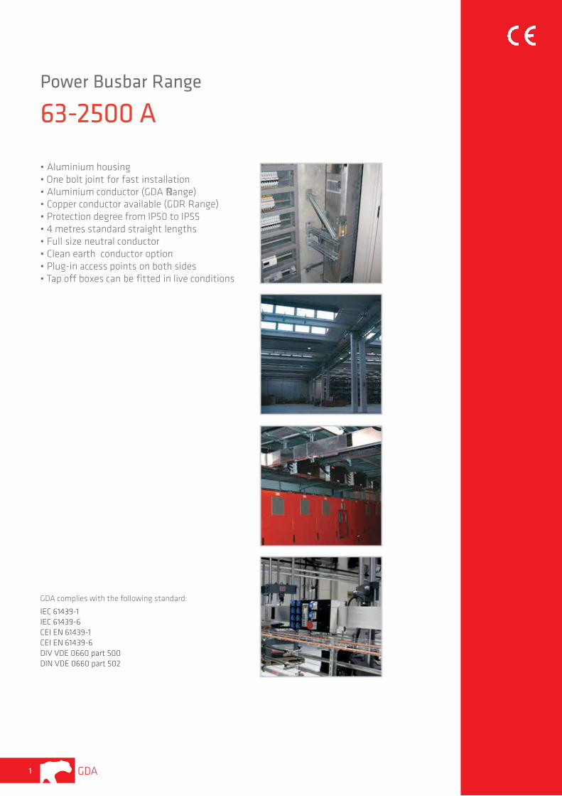
• Aluminium housing • One bolt joint for fast installation• Aluminium conductor (GDA �Range)• Copper conductor available (GDR Range)• Protection degree from IP50 to IP55 • 4 metres standard straight lengths• Full size neutral conductor• Clean earth conductor option• Plug-in access points on both sides • Tap off boxes can be fitted in live conditions
Power Busbar Range
63-2500 A
GDA complies with the following standard:
IEC 61439-1IEC 61439-6CEI EN 61439-1CEI EN 61439-6DIV VDE 0660 part 500DIN VDE 0660 part 502
GDA 2
AGDA 4 GDA 5
Code Kg/m Code Kg/m Tap off points
63 GDA100630 3,0 GDA200630 3,3 4+0
100 GDA1 00000 3,1 GDA200000 3,4 4+0
160 GDA101000M 3,3 GDA201000M 3,6 4+0
250 GDA102000 4,4 GDA202000 4,7 4+4
400 GDA104000 6,2 GDA204000 6,5 4+4
500 GDA105000 7,7 GDA205000 8,4 4+4
630 GDA106000 9,0 GDA206000 9,7 4+4
800 GDA108000 10,0 GDA208000 10,7 4+4
1000 GDA110000 11,3 GDA210000 12,1 4+4
1250 GDA112000 14,7 GDA212000 15,6 4+0
1600 GDA116000 17,7 GDA216000 18 4+0
2000 GDA120000 25 GDA220000 26 4+4
2500 GDA125000 28 GDA225000 29 4+4
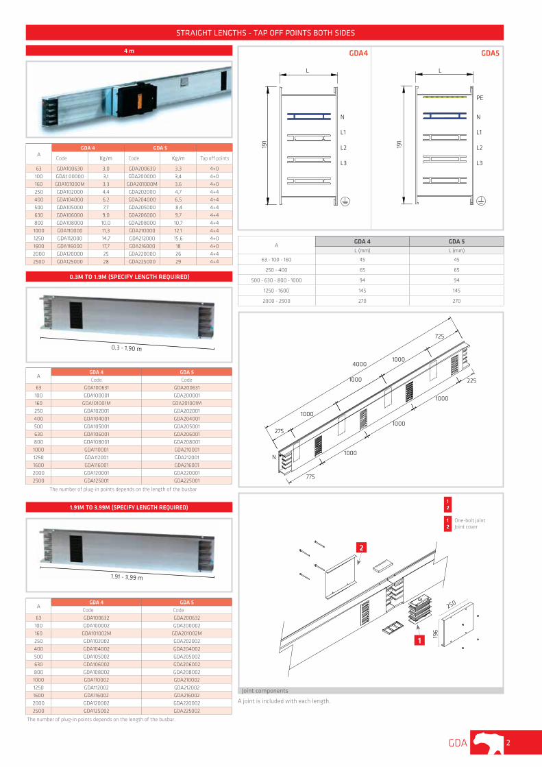
STRAIGHT LENGTHS - TAP OFF POINTS BOTH SIDES
AGDA 4 GDA 5Code Code
63 GDA100631 GDA200631
100 GDA100001 GDA200001
160 GDA101001M GDA201001M
250 GDA102001 GDA202001
400 GDA104001 GDA204001
500 GDA105001 GDA205001
630 GDA106001 GDA206001
800 GDA108001 GDA208001
1000 GDA110001 GDA210001
1250 GDA112001 GDA212001
1600 GDA116001 GDA216001
2000 GDA120001 GDA220001
2500 GDA125001 GDA225001
The number of plug-in points depends on the length of the busbar
AGDA 4 GDA 5
Code Code
63 GDA100632 GDA200632
100 GDA100002 GDA200002
160 GDA101002M GDA201002M
250 GDA102002 GDA202002
400 GDA104002 GDA204002
500 GDA105002 GDA205002
630 GDA106002 GDA206002
800 GDA108002 GDA208002
1000 GDA110002 GDA210002
1250 GDA112002 GDA212002
1600 GDA116002 GDA216002
2000 GDA120002 GDA220002
2500 GDA125002 GDA225002
The number of plug-in points depends on the length of the busbar.
0,3 - 1,90 m
1,91 - 3,99 m
250
196
1
2
Joint components
AGDA 4 GDA 5L (mm) L (mm)
63 - 100 - 160 45 45
250 - 400 65 65
500 - 630 - 800 - 1000 94 94
1250 - 1600 145 145
2000 - 2500 270 270
L
191
N
L1
L2
L3
N
L1
L2
L3
191
L
PE
A joint is included with each length.
4 m
0.3M TO 1.9M (SPECIFY LENGTH REQUIRED)
1.91M TO 3.99M (SPECIFY LENGTH REQUIRED)
4000
1000
1000
1000
275
725
1000
1000
1000
225
775
N
GDA4 GDA5
1 2
1 One-bolt joint2 Joint cover
GDA3
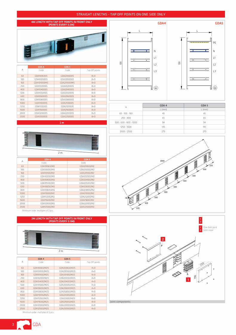
STRAIGHT LENGTHS - TAP OFF POINTS ON ONE SIDE ONLY
AGDA 4 GDA 5Code Code Tap Off points
63 GDA100630S GDA200630S 8+0
100 GDA100000S GDA200000S 8+0
160 GDA101000MS GDA201000MS 8+0
250 GDA102000S GDA202000S 8+0
400 GDA104000S GDA204000S 8+0
500 GDA105000S GDA205000S 8+0
630 GDA106000S GDA206000S 8+0
800 GDA108000S GDA208000S 8+0
1000 GDA110000S GDA210000S 8+0
1250 GDA112000S GDA212000S 8+0
1600 GDA116000S GDA216000S 8+0
2000 GDA120000S GDA220000S 8+0
2500 GDA125000S GDA225000S 8+0
AGDA 4 GDA 5
Code Code
63 GDA100632M2 GDA200632M2
100 GDA100002M2 GDA200002M2
160 GDA101002M2 GDA201002M2
250 GDA102002M2 GDA202002M2
400 GDA104002M2 GDA204002M2
500 GDA105002M2 GDA205002M2
630 GDA106002M2 GDA206002M2
800 GDA108002M2 GDA208002M2
1000 GDA110002M2 GDA210002M2
1250 GDA112002M2 GDA212002M2
1600 GDA116002M2 GDA216002M2
2000 GDA120002M2 GDA220002M2
2500 GDA125002M2 GDA225002M2
Minimum order: multiples of 2 pcs.
2 m
2 m
AGDA 4 GDA 5Code Code Tap Off points
63 GDA100632M2S GDA200632M2S 4+0
100 GDA100002M2S GDA200002M2S 4+0
160 GDA101002M2S GDA201002M2S 4+0
250 GDA102002M2S GDA202002M2S 4+0
400 GDA104002M2S GDA204002M2S 4+0
500 GDA105002M2S GDA205002M2S 4+0
630 GDA106002M2S GDA206002M2S 4+0
800 GDA108002M2S GDA208002M2S 4+0
1000 GDA110002M2S GDA210002M2S 4+0
1250 GDA112002M2S GDA212002M2S 4+0
1600 GDA116002M2S GDA216002M2S 4+0
2000 GDA120002M2S GDA220002M2S 4+0
2500 GDA125002M2S GDA250002M2S 4+0
Minimum order: multiples of 2 pcs.
4M LENGTH WITH TAP OFF POINTS IN FRONT ONLY(POINTS EVERY 0.5M)
2 m
2M LENGTH WITH TAP OFF POINTS IN FRONT ONLY(POINTS EVERY 0.5M)
AGDA 4 GDA 5L (mm) L (mm)
63 - 100 - 160 45 45
250 - 400 65 65
500 - 630 - 800 - 1000 94 94
1250 - 1600 145 145
2000 - 2500 270 270
L
191
N
L1
L2
L3
N
L1
L2
L3
191
L
PE
GDA4 GDA5
250
196
1
2
Joint components
1 2
1 One-bolt joint2 Joint cover
4000
225
N
500
500
500
500
500
500
500
225
GDA 4
A
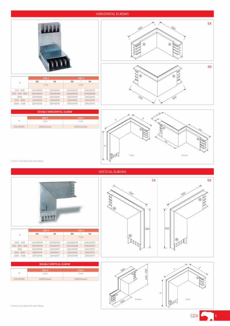
GDA 4 GDA 5DX SX DX SX
Code Code
250 - 400 GDA100102 GDA100101 GDA200102 GDA200101
500 - 630 - 800 GDA100106 GDA100105 GDA200106 GDA200105
1000 GDA100116 GDA100115 GDA200116 GDA200115
1250 - 1600 GDA116116 GDA116115 GDA216116 GDA216115
2000 - 2500 GDA120116 GDA120115 GDA220116 GDA220115
HORIZONTAL ELBOWS
500500
N N
SX
VERTICAL ELBOWS
A
GDA 4 GDA 5DX SX DX SX
Code Code
250v - 400 GDA100104 GDA100103 GDA200104 GDA200103
500 - 630 - 800 GDA100108 GDA100107 GDA200108 GDA200107
1000 GDA100118 GDA100117 GDA200118 GDA200117
1250 - 1600 GDA116118 GDA116117 GDA216118 GDA216117
2000 - 2500 GDA120118 GDA120117 GDA220118 GDA220117
500
500
N
N
500
500
N
N
min
= 4
32
DX
SX
500
500
N
N
DX
AGDA 4 GDA 5Code Code
250/2500A GDA1Zxxxxxx GDA2Zxxxxxx
DOUBLE VERTICAL ELBOW
AGDA 4 GDA 5Code Code
250/2500A GDA1Zxxxxxx GDA2Zxxxxxx
DOUBLE HORIZONTAL ELBOW
500 500
N N
A joint is included with each elbow.
YZ
X
N
N
A joint is included with each elbow.
YZ
X
N
N
X = 2L+50
L
N
N
500
500
Triple Double
TripleDouble
GDA5
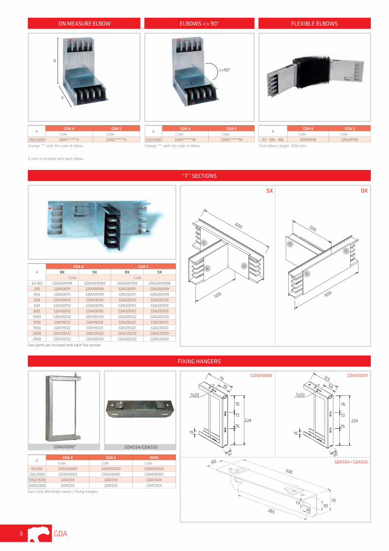
ON MEASURE ELBOW ELBOWS <> 90° FLEXIBLE ELBOWS
AGDA 4 GDA 5
Code Code
250/2500 GDA1*****S GDA2*****S
Change “*” with the code of elbow.
A joint is included with each elbow.
X
y
<>90°
AGDA 4 GDA 5
Code Code
250/2500 GDA1*****M GDA2*****M
Change “*” with the code of elbow.
AGDA 4 GDA 5
Code Code
63 - 100 - 160 GDA1FX16 GDA2FX16
Total elbow Length: 1000 mm.
A
GDA 4 GDA 5DX SX DX SX
Code Code
63-160 GDA100111M GDA100109M GDA200111M GDA200109M
250 GDA100111 GDA100109 GDA200111 GDA200109
400 GDA100111 GDA100109 GDA200111 GDA200109
500 GDA100112 GDA100110 GDA200112 GDA200110
630 GDA100112 GDA100110 GDA200112 GDA200110
800 GDA100112 GDA100110 GDA200112 GDA200110
1000 GDA100122 GDA100120 GDA200122 GDA200120
1250 GDA116122 GDA116120 GDA216122 GDA216120
1600 GDA116122 GDA116120 GDA216122 GDA216120
2000 GDA120122 GDA120120 GDA220220 GDA220120
2500 GDA120122 GDA120120 GDA220220 GDA220120
Two joints are included with each Tee section
“T” SECTIONS
600
500
N
N N
600
500
N
N
N
SX DX
AGDA 4 GDA 5 INOX
Code Code Code
63/160 GDA010000 GDA010000 GDA01000X
250/1000 GDA010001 GDA010001 GDA01000X
1250/1600 GDASS4 GDASS4 GDASS4X
2000/2500 GDASS5 GDASS5 GDASS5X
Each GDA 4M length needs 2 fixing hangers.
GDA01000* GDASS4/GDASS5
79
39
7x20
15
30
76
72
76224
123
59
7x20
15
30
76
72
76224
FIXING HANGERS
GDASS4 • GDASS5
GDA010001GDA010000
330
60
70
26530
1335
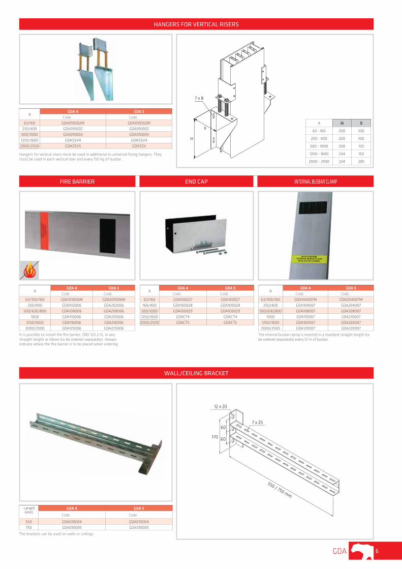
GDA 6
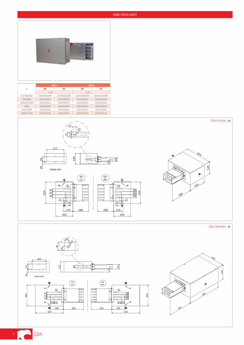
FIRE BARRIER END CAP INTERNAL BUSBAR CLAMP
AGDA 4 GDA 5
Code Code
63/100/160 GDA104007M GDA204007M
250/400 GDA104007 GDA204007
500/630/800 GDA108007 GDA208007
1000 GDA110007 GDA210007
1250/1600 GDA160007 GDA260007
2000/2500 GDA120007 GDA220007
The internal busbar clamp is inserted in a standard straight length (tobe ordered separately) every 12 m of busbar.
AGDA 4 GDA 5
Code Code
63/160 GDA100027 GDA100027
160/400 GDA100028 GDA100028
500/1000 GDA100029 GDA100029
1250/1600 GDACT4 GDACT4
2000/2500 GDACT5 GDACT5
AGDA 4 GDA 5
Code Code
63/100/160 GDA101006M GDA201006M
250/400 GDA102006 GDA202006
500/630/800 GDA108006 GDA208006
1000 GDA110006 GDA210006
1250/1600 GDA116006 GDA216006
2000/2500 GDA125006 GDA225006
It is possible to install the fire barrier, (REI 120 2 h), in anystraight length or elbow (to be ordered separately). Alwaysindicate where the fire barrier is to be placed when ordering.
HANGERS FOR VERTICAL RISERS
AGDA 4 GDA 5
Code Code
63/160 GDA010002M GDA010002M
250/400 GDA010002 GDA010002
500/1000 GDA010003 GDA010003
1250/1600 GDASSV4 GDASSV4
2000/2500 GDASSV5 GDASSV
Hangers for vertical risers must be used in additional to universal fixing hangers. Theymust be used in each vertical riser and every 150 kg of busbar. .
WALL/CEILING BRACKET
Length (mm)
GDA 4 GDA 5
Code Code
550 GDA010004 GDA010004
750 GDA010005 GDA010005
The brackets can be used on walls or ceilings.
550 / 750 mm
12 x 20
7 x 2560
60170
7 x 8
H
XA H X
63 - 160 200 100
250 - 400 200 100
500 - 1000 200 125
1250 - 1600 234 153
2000 - 2500 234 285
GDA7
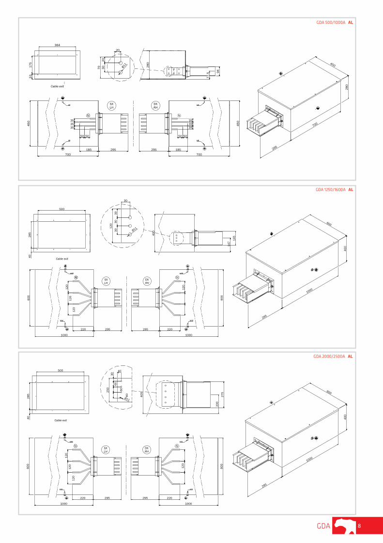
END FEED UNIT
A
GDA 4 GDA 5DX SX DX SX
Code Code
63/100/160 GDA100021M GDA100020M GDA200021M GDA200020M
250/400 GDA100021 GDA100020 GDA200021 GDA200020
500/630/800 GDA100023 GDA100022 GDA200023 GDA200022
1000 GDA100043 GDA100042 GDA200043 GDA200042
1250/1600 GDA116043 GDA116042 GDA216043 GDA216042
2000/2500 GDA120043 GDA120042 GDA220043 GDA220042
GDA 63/160A AL
GDA 250/400A AL
185
10
Ø9
55
N
SXLH
DXRH
45126
20 ==
126
200
254
185
200
110
353535
254
200
55
Cable exit28
185
N
200
110
353535
254
152
400
300
295
50 50
185 295
20
Ø11
76
N353535
5050
185295
N353535
SXLH
DXRH
300
65152
40
40
20
400 400
300
75
200
Cable exit39
GDA 8
GDA 1250/1600A AL
GDA 500/1000A AL
GDA 2000/2500A AL
50 50
185 295
3020
20
Ø11
77.5
N353535
5050
185295
N353535
SXLH
DXRH
450
94
280
280
700
450
295
70
700 700
450
175
364
Cable exit
53
295
147
NSXLH
DXRH
600
14540
0
120
120
120
220
1000
295
N
600
120
220
1000
400
1000
600
295
285
500
Cable exit40
295
200
NSXLH
DXRH
600
275
400
120
120
120
220
1000
295
N
600
120
220
1000
400
1000
600
295
285
500
Cable exit40
40
3060
60
60
250
Ø11
GDA9
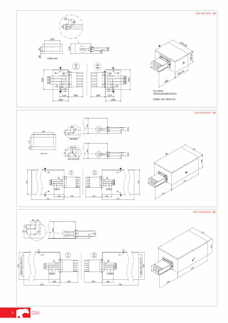
GDR 400/800A CU
GDR 100/250A CU
3020
25
Ø11
77.5 94
70
25
50 50
185 295
N353535
5050
185295
N353535
SXLH
DXRH
450
700 700
Cab
le e
ntr
y 36
4x17
5
450
Cab
le e
ntr
y 36
4x17
5
700
450
295
GDR 1250/1600A CU
400
126
(h)
200 (A)
254 (B)
185
For 250A:400(A)x300(B)x152(h)
Cable exit: 364x175185
10
Ø9
55
N
SXLH
DXRH
45126
20 ==
200
110
353535
254
20055
Cable exit28
185
N
200
110
353535
254
280
77.5 65
15
Ø11
40
20
20
50 50
185 295
N353535
5050
185295
N353535
SXLH
DXRH
450
700 700
450
175
364
Cable exit
53
280
700
450
295
20
Ø11
30 15
GDR 400A
280
77.5 65
GDR 630/800A
GDA 10
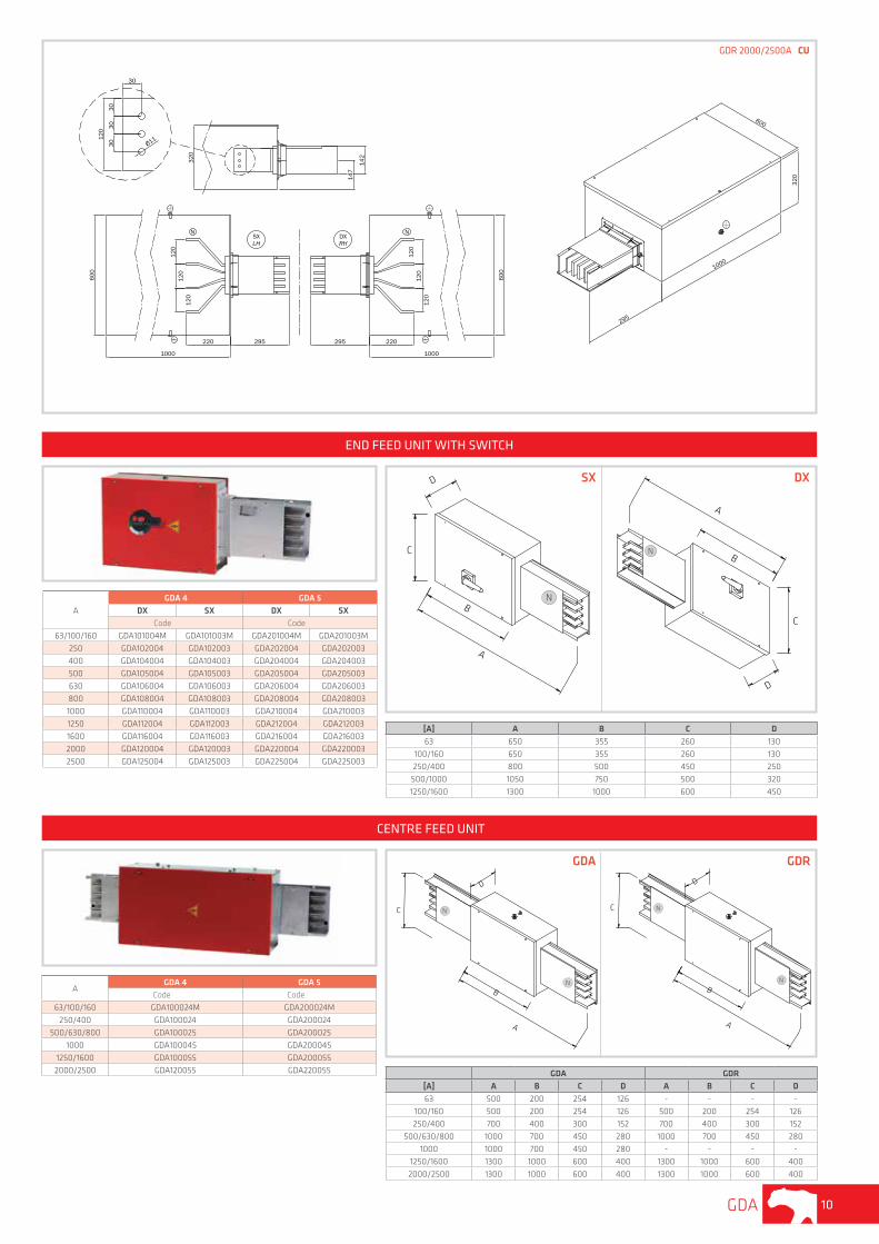
[A] A B C D
63 650 355 260 130100/160 650 355 260 130
250/400 800 500 450 250
500/1000 1050 750 500 320
1250/1600 1300 1000 600 450
A
B
D
C
N
A
B
D
C
N
SX DX
142
320
295
NSXLH
DXRH
600
120
120
120
220
1000
295
N
600
120
120
120
220
1000
320
1000
600
295
GDR 2000/2500A CU
END FEED UNIT WITH SWITCH
A
GDA 4 GDA 5DX SX DX SX
Code Code
63/100/160 GDA101004M GDA101003M GDA201004M GDA201003M
250 GDA102004 GDA102003 GDA202004 GDA202003
400 GDA104004 GDA104003 GDA204004 GDA204003
500 GDA105004 GDA105003 GDA205004 GDA205003
630 GDA106004 GDA106003 GDA206004 GDA206003
800 GDA108004 GDA108003 GDA208004 GDA208003
1000 GDA110004 GDA110003 GDA210004 GDA210003
1250 GDA112004 GDA112003 GDA212004 GDA212003
1600 GDA116004 GDA116003 GDA216004 GDA216003
2000 GDA120004 GDA120003 GDA220004 GDA220003
2500 GDA125004 GDA125003 GDA225004 GDA225003
AGDA 4 GDA 5
Code Code
63/100/160 GDA100024M GDA200024M
250/400 GDA100024 GDA200024
500/630/800 GDA100025 GDA200025
1000 GDA100045 GDA200045
1250/1600 GDA100055 GDA200055
2000/2500 GDA120055 GDA220055
CENTRE FEED UNIT
C
D
B
A
N
N
C
D
B
A
N
N
GDA GDR
[A] A B C D A B C D
63 500 200 254 126 - - - -100/160 500 200 254 126 500 200 254 126
250/400 700 400 300 152 700 400 300 152
500/630/800 1000 700 450 280 1000 700 450 280
1000 1000 700 450 280 - - - -
1250/1600 1300 1000 600 400 1300 1000 600 400
2000/2500 1300 1000 600 400 1300 1000 600 400
GDA GDR
147
GDA11
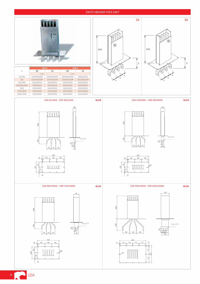
SWITCHBOARD FEED UNIT
A
GDA 4 GDA 5DX SX DX SX
Code Code
63/100 GDA100030M GDA100032M GDA200030M GDA200032
160 GDA100030M GDA100032M GDA200030M GDA200032M
250/400 GDA100030 GDA100032 GDA200030 GDA200032
500/630/800 GDA100031 GDA100033 GDA200031 GDA200033
1000 GDA100051 GDA100053 GDA200051 GDA200053
1250/1600 GDA100061 GDA100063 GDA200061 GDA200063
2000/2500 GDA120061 GDA120063 GDA220061 GDA220063
400
X
YY
Y
N
400
X
YY
Y
N
Hole Ø11
400
100
70 70 70
20
4020
Hole Ø 11
65
350
110 110 11010
170
7575
10
Ø 7
Holes Ø11
20
70
20
Holes Ø 11
94
30
400
100
350
110 110 11010
200
9090
10
Ø 7
70 70 70
Holes Ø10
400
200
120 120 120
30
12030
Holes Ø 10
145
30 30
GDA 63/160A - GDR 100/250A AL/CU
Hole Ø9
400
100
70 70 70
20
1020
Hole Ø 9
45
350
110 110 11010
170
7575
10
GDA 250/400A - GDR 400/800A AL/CU
GDA 500/1000A - GDR 1250/1600A AL/CU GDA 1250/1600A - GDR 2000/2500A AL/CU
SX DX
GDA 12
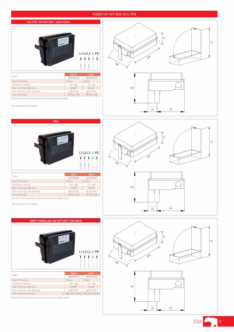
CodeGDA 4 GDA 5
GDA400250 GDA400250
Tap off material Plastic Plastic
Conductor material Cu + Ag Cu + Ag
Max incoming cable size 6 mm2 6 mm2
Max incoming cable diameter ø 22,5 mm ø 22,5 mm
Fuse base type CF 10,3 x 38 CF 10,3 x 38
Tap off can be inserted on each side of every straight length
The fuses are not included.
CodeGDA 4 GDA 5
GDA400251 GDA400251
Tap Off Material Plastic Plastic
Conductor material Cu + Ag Cu + Ag
Max incoming cable size 6 mm2 6 mm2
Max incoming cable diameter ø 22,5 mm ø 22,5 mm
Fuse base type CF 10,3 x 38 CF 10,3 x 38
Tap off can be inserted on each side of every straight length
The fuses are not included.
FUSED TAP OFF BOX 32 A TPN
CodeGDA 4 GDA 5
GDA400253 GDA400253
Tap Off Material Plastic Plastic
Conductor material Cu + Ag Cu + Ag
Max incoming cable size 6 mm2 6 mm2
Max incoming cable diameter ø 22,5 mm ø 22,5 mm
Free inside space (mm) 185 x 45 x 60 (h) 185 x 45 x 60 (h) �
Tap off can be inserted on each side of every straight length
32A TPN TAP OFF UNIT LESS FUSES
PEN
EMPTY MODULAR TAP OFF UNIT FOR MCCB
146
204
71
71
121
11135
146
204
71
71
121
11135
146
204
71
71
121
11135
GDA13
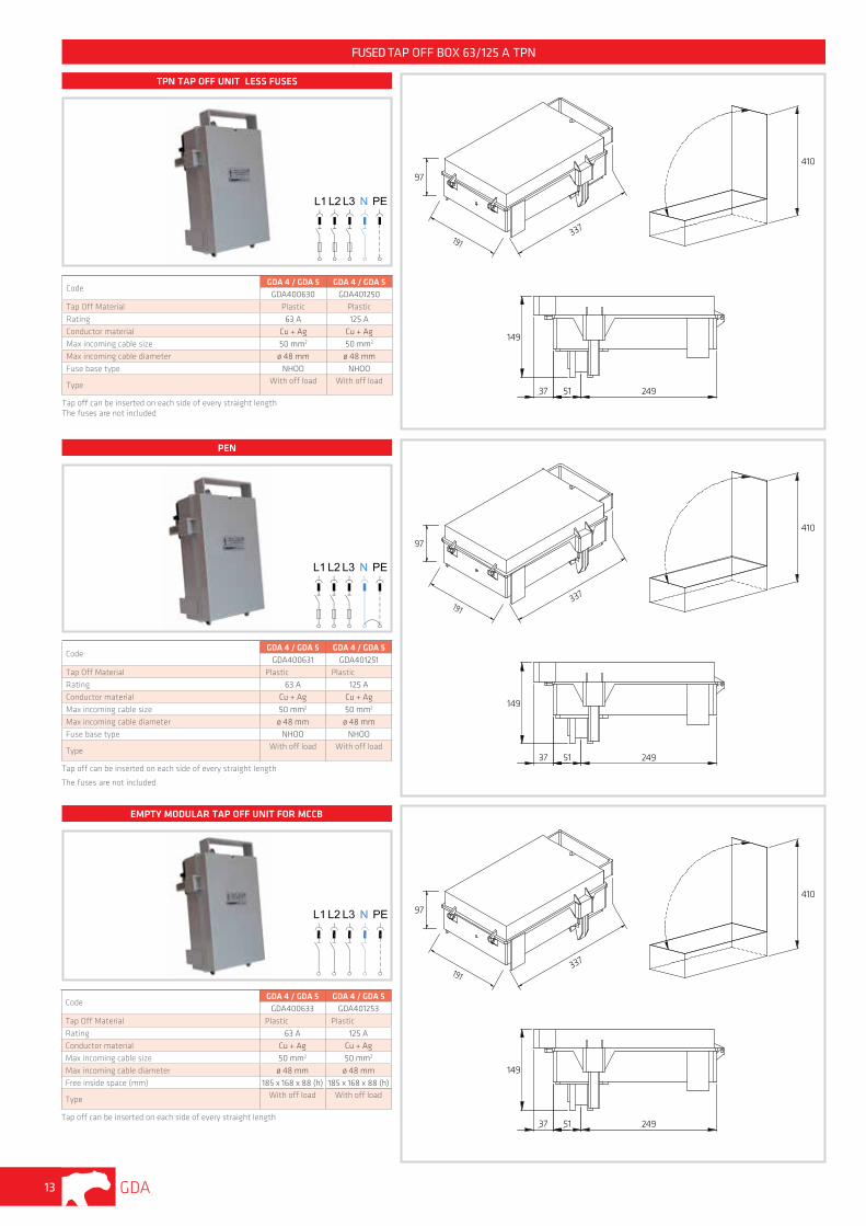
FUSED TAP OFF BOX 63/125 A TPN
CodeGDA 4 / GDA 5 GDA 4 / GDA 5
GDA400630 GDA401250
Tap Off Material Plastic Plastic
Rating 63 A 125 A
Conductor material Cu + Ag Cu + Ag
Max incoming cable size 50 mm2 50 mm2
Max incoming cable diameter ø 48 mm ø 48 mm
Fuse base type NHOO NHOO
Type With off load With off load
Tap off can be inserted on each side of every straight lengthThe fuses are not included
CodeGDA 4 / GDA 5 GDA 4 / GDA 5
GDA400631 GDA401251
Tap Off Material Plastic Plastic
Rating 63 A 125 A
Conductor material Cu + Ag Cu + Ag
Max incoming cable size 50 mm2 50 mm2
Max incoming cable diameter ø 48 mm ø 48 mm
Fuse base type NHOO NHOO
Type With off load With off load
Tap off can be inserted on each side of every straight length
The fuses are not included
CodeGDA 4 / GDA 5 GDA 4 / GDA 5
GDA400633 GDA401253
Tap Off Material Plastic Plastic
Rating 63 A 125 A
Conductor material Cu + Ag Cu + Ag
Max incoming cable size 50 mm2 50 mm2
Max incoming cable diameter ø 48 mm ø 48 mm
Free inside space (mm) 185 x 168 x 88 (h) 185 x 168 x 88 (h)
Type With off load With off load
Tap off can be inserted on each side of every straight length
TPN TAP OFF UNIT LESS FUSES
PEN
EMPTY MODULAR TAP OFF UNIT FOR MCCB
191337
97
410
149
2495137
191337
97
410
149
2495137
191337
97
410
149
2495137

GDA 14
FUSED TAP OFF BOX 160/250/400 A TPN
CodeGDA 4 / GDA 5 GDA 4 / GDA 5 GDA 4 / GDA 5GDA401600 GDA402500 GDA404000
Tap Off Material Steel Steel Steel
Rating 160 A 250 A 400 A
Conductor material Cu + Ag Cu + Ag Cu + Ag
Max incoming cable size 70 mm2 150 mm2 185 mm2
Max incoming cable diameter 180 x 50 mm 16O x 60 mm 16O x 60 mm
Fuse base type NHOO NH1 NH2
Type With off load With off load With off load
Tap off can be inserted on each side of every straight lengthThe fuses are not included
CodeGDA 4 / GDA 5 GDA 4 / GDA 5 GDA 4 / GDA 5
GDA401601 GDA402501 GDA404001
Tap Off Material Steel Steel Steel
Rating 160 A 250 A 400 A
Conductor material Cu + Ag Cu + Ag Cu + Ag
Max incoming cable size 70 mm2 150 mm2 185 mm2
Max incoming cable diameter 180 x 50 mm 16O x 60 mm 16O x 60 mm
Fuse base type NHOO NH1 NH2
Type With off load With off load With off load
Tap off can be inserted on each side of every straight lengthThe fuses are not included
CodeGDA 4 / GDA 5 GDA 4 / GDA 5 GDA 4 / GDA 5
GDA401603 GDA402503 GDA404003
Tap Off Material Steel Steel Steel
Rating 160 A 250 A 400 A
Conductor material Cu + Ag Cu + Ag Cu + Ag
Max incoming cable size 70 mm2 150 mm2 185 mm2
Max incoming cable diameter 180 x 50 mm 16O x 60 mm 16O x 60 mmFree inside space (mm) 240 x 240 x
125 (h)250 x 380 x
125 (h) 250 x 480 x
185 (h)
Type With off load With off load With off load
Tap off can be inserted on each side of every straight length
560
300
140
677
300
200
490
675
855
140
48278
200
59978
GDA 401600/1/3 - 160 A
GDA 402500/1/3 - 250 A
GDA 404000/1/3 - 400 A
TPN TAP OFF UNIT LESS FUSES
PEN
EMPTY MODULE TAP OFF UNIT FOR MCCB
420290
140
140
78 342
GDA15
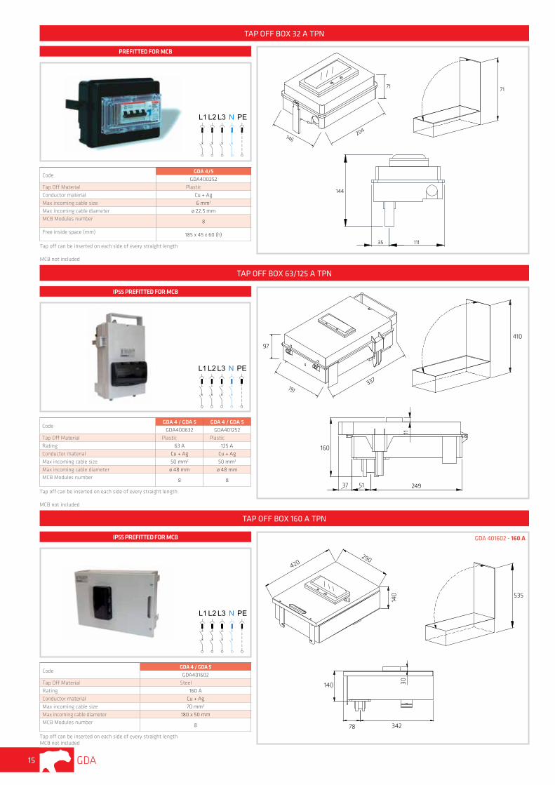
TAP OFF BOX 32 A TPN
CodeGDA 4/5
GDA400252
Tap Off Material Plastic
Conductor material Cu + Ag
Max incoming cable size 6 mm2
Max incoming cable diameter ø 22,5 mmMCB Modules number 8
Free inside space (mm) 185 x 45 x 60 (h)
Tap off can be inserted on each side of every straight length
MCB not included
CodeGDA 4 / GDA 5 GDA 4 / GDA 5
GDA400632 GDA401252
Tap Off Material Plastic Plastic
Rating 63 A 125 A
Conductor material Cu + Ag Cu + Ag
Max incoming cable size 50 mm2 50 mm2
Max incoming cable diameter ø 48 mm ø 48 mmMCB Modules number 8 8
Tap off can be inserted on each side of every straight length
MCB not included
146204
71 71
144
35 111
TAP OFF BOX 63/125 A TPN
191337
97
410
160
2495137
11
PREFITTED FOR MCB
IP55 PREFITTED FOR MCB
TAP OFF BOX 160 A TPN
CodeGDA 4 / GDA 5
GDA401602
Tap Off Material Steel
Rating 160 A
Conductor material Cu + Ag
Max incoming cable size 70 mm2
Max incoming cable diameter 180 x 50 mmMCB Modules number 8
Tap off can be inserted on each side of every straight lengthMCB not included
GDA 401602 - 160 A
420290
140
43535
140
78 342
30
IP55 PREFITTED FOR MCB
GDA 16
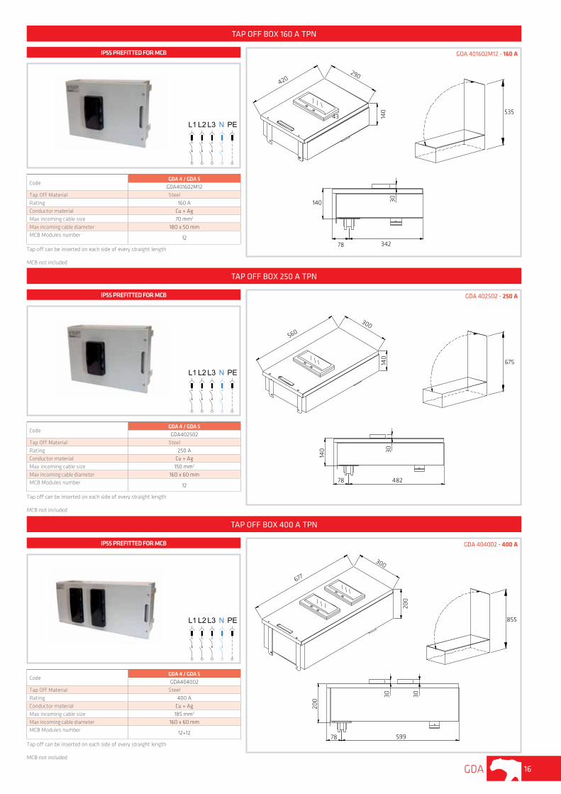
TAP OFF BOX 250 A TPN
CodeGDA 4 / GDA 5GDA402502
Tap Off Material Steel
Rating 250 A
Conductor material Cu + Ag
Max incoming cable size 150 mm2
Max incoming cable diameter 16O x 60 mmMCB Modules number 12
Tap off can be inserted on each side of every straight length
MCB not included
GDA 402502 - 250 AIP55 PREFITTED FOR MCB
TAP OFF BOX 400 A TPN
CodeGDA 4 / GDA 5GDA404002
Tap Off Material Steel
Rating 400 A
Conductor material Cu + Ag
Max incoming cable size 185 mm2
Max incoming cable diameter 16O x 60 mmMCB Modules number 12+12
Tap off can be inserted on each side of every straight length
MCB not included
GDA 404002 - 400 AIP55 PREFITTED FOR MCB
560
TAP OFF BOX 160 A TPN
CodeGDA 4 / GDA 5
GDA401602M12
Tap Off Material Steel
Rating 160 A
Conductor material Cu + Ag
Max incoming cable size 70 mm2
Max incoming cable diameter 18O x 50 mmMCB Modules number 12
Tap off can be inserted on each side of every straight length
MCB not included
GDA 401602M12 - 160 AIP55 PREFITTED FOR MCB
420290
140
43535
140
78 342
30
300
140
675
140 30
78 482
677
300
200
855
200
30 30
78 599
GDA17
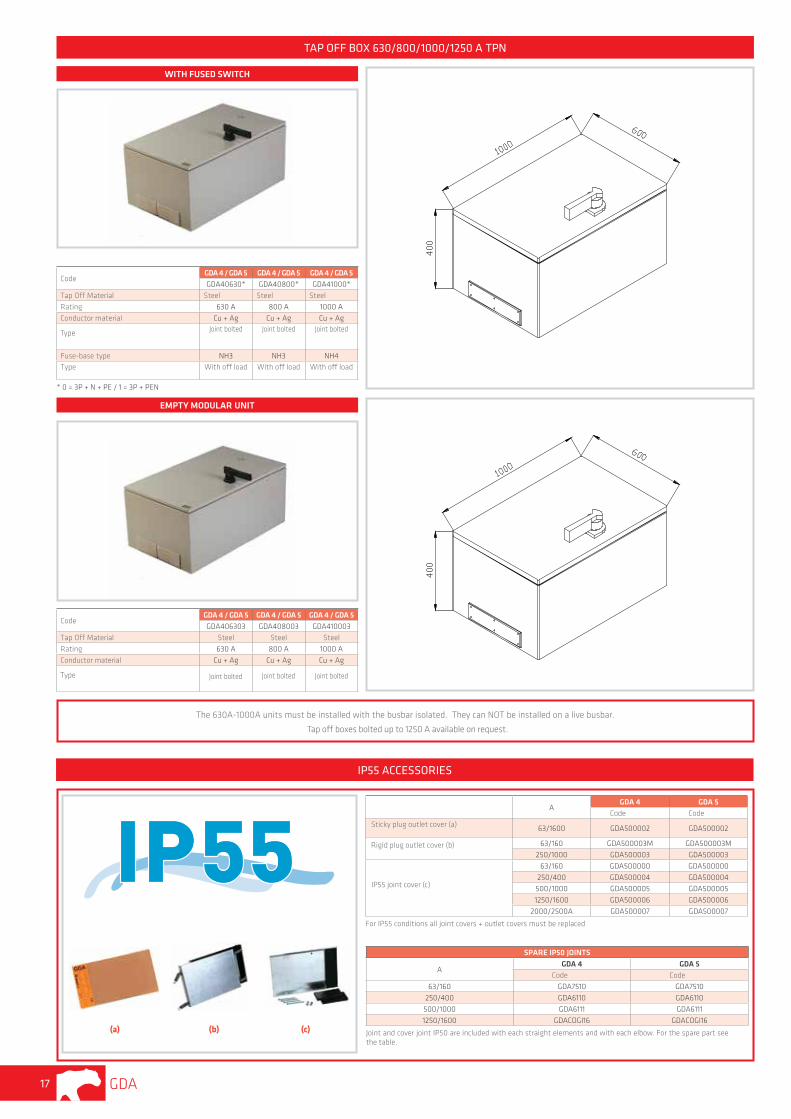
TAP OFF BOX 630/800/1000/1250 A TPN
CodeGDA 4 / GDA 5 GDA 4 / GDA 5 GDA 4 / GDA 5GDA40630* GDA40800* GDA41000*
Tap Off Material Steel Steel Steel
Rating 630 A 800 A 1000 A
Conductor material Cu + Ag Cu + Ag Cu + Ag
Type Joint bolted Joint bolted Joint bolted
Fuse-base type NH3 NH3 NH4Type With off load With off load With off load
* 0 = 3P + N + PE / 1 = 3P + PEN
CodeGDA 4 / GDA 5 GDA 4 / GDA 5 GDA 4 / GDA 5GDA406303 GDA408003 GDA410003
Tap Off Material Steel Steel Steel
Rating 630 A 800 A 1000 A
Conductor material Cu + Ag Cu + Ag Cu + Ag
Type Joint bolted Joint bolted Joint bolted
WITH FUSED SWITCH
EMPTY MODULAR UNIT
The 630A-1000A units must be installed with the busbar isolated. They can NOT be installed on a live busbar.
Tap off boxes bolted up to 1250 A available on request.
IP55 ACCESSORIES
(a) (b) (c)
AGDA 4 GDA 5
Code CodeSticky plug outlet cover (a) 63/1600 GDA500002 GDA500002
Rigid plug outlet cover (b) 63/160 GDA500003M GDA500003M
250/1000 GDA500003 GDA500003
IP55 joint cover (c)
63/160 GDA500000 GDA500000
250/400 GDA500004 GDA500004
500/1000 GDA500005 GDA500005
1250/1600 GDA500006 GDA500006
2000/2500A GDA500007 GDA500007
For IP55 conditions all joint covers + outlet covers must be replaced
SPARE IP50 JOINTS
AGDA 4 GDA 5
Code Code
63/160 GDA7510 GDA7510
250/400 GDA6110 GDA6110
500/1000 GDA6111 GDA6111
1250/1600 GDACOGI16 GDACOGI16
Joint and cover joint IP50 are included with each straight elements and with each elbow. For the spare part seethe table.
GDA 18
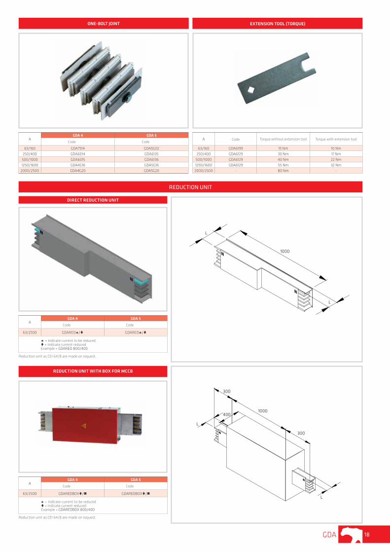
AGDA 4 GDA 5
Code Code
63/2500 GDAREDBOX/n GDAREDBOX/n
= indicate current to be reduced = indicate current reducedExample = GDAREDBOX 800/400
Reduction unit as CEI 64/8 are made on request.
AGDA 4 GDA 5
Code Code
63/2500 GDARED / GDARED /
= indicate current to be reduced = indicate current reducedExample = GDARED 800/400
Reduction unit as CEI 64/8 are made on request.
DIRECT REDUCTION UNIT
REDUCTION UNIT WITH BOX FOR MCCB
1000
L
L
300
1000
300
400
L
L
REDUCTION UNIT
AGDA 4 GDA 5
Code Code
63/160 GDA7514 GDA5G02
250/400 GDA6014 GDA6135
500/1000 GDA6015 GDA6136
1250/1600 GDA4G16 GDA5G162000/2500 GDA4G20 GDA5G20
A Code Torque without extension tool Torque with extension tool
63/160 GDA6199 15 Nm 10 Nm
250/400 GDA6129 30 Nm 17 Nm
500/1000 GDA6129 40 Nm 22 Nm
1250/1600 GDA6129 55 Nm 32 Nm
2000/2500 - 80 Nm -
EXTENSION TOOL (TORQUE) ONE-BOLT JOINT
GDA19
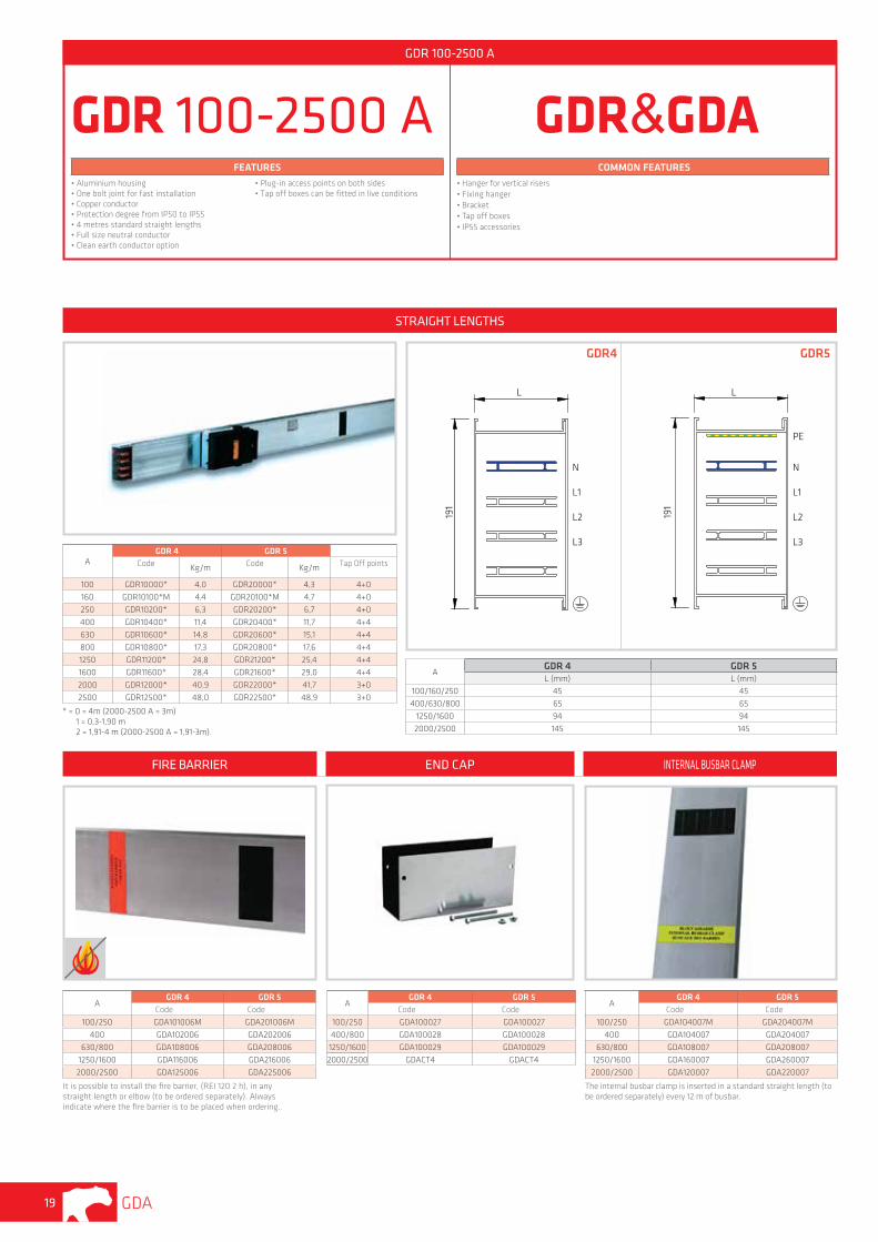
GDR 100-2500 A
GDR 100-2500 AFEATURES
• Aluminium housing• One bolt joint for fast installation• Copper conductor• Protection degree from IP50 to IP55• 4 metres standard straight lengths• Full size neutral conductor• Clean earth conductor option
GDR&GDACOMMON FEATURES
• Hanger for vertical risers• Fixing hanger• Bracket• Tap off boxes• IP55 accessories
AGDR 4 GDR 5
Code Kg/m Code Kg/m Tap Off points
100 GDR10000* 4,0 GDR20000* 4,3 4+0
160 GDR10100*M 4,4 GDR20100*M 4,7 4+0
250 GDR10200* 6,3 GDR20200* 6,7 4+0
400 GDR10400* 11,4 GDR20400* 11,7 4+4
630 GDR10600* 14,8 GDR20600* 15,1 4+4
800 GDR10800* 17,3 GDR20800* 17,6 4+4
1250 GDR11200* 24,8 GDR21200* 25,4 4+4
1600 GDR11600* 28,4 GDR21600* 29,0 4+4
2000 GDR12000* 40,9 GDR22000* 41,7 3+0
2500 GDR12500* 48,0 GDR22500* 48,9 3+0
* = 0 = 4m (2000-2500 A = 3m) 1 = 0,3-1,90 m 2 = 1,91-4 m (2000-2500 A = 1,91-3m).
AGDR 4 GDR 5L (mm) L (mm)
100/160/250 45 45
400/630/800 65 65
1250/1600 94 94
2000/2500 145 145
L
191
N
L1
L2
L3
N
L1
L2
L3
191
L
PE
GDR4 GDR5
STRAIGHT LENGTHS
FIRE BARRIER END CAP INTERNAL BUSBAR CLAMP
AGDR 4 GDR 5
Code Code
100/250 GDA104007M GDA204007M
400 GDA104007 GDA204007
630/800 GDA108007 GDA208007
1250/1600 GDA160007 GDA260007
2000/2500 GDA120007 GDA220007
The internal busbar clamp is inserted in a standard straight length (tobe ordered separately) every 12 m of busbar.
AGDR 4 GDR 5
Code Code
100/250 GDA100027 GDA100027
400/800 GDA100028 GDA100028
1250/1600 GDA100029 GDA100029
2000/2500 GDACT4 GDACT4
AGDR 4 GDR 5
Code Code
100/250 GDA101006M GDA201006M
400 GDA102006 GDA202006
630/800 GDA108006 GDA208006
1250/1600 GDA116006 GDA216006
2000/2500 GDA125006 GDA225006
It is possible to install the fire barrier, (REI 120 2 h), in anystraight length or elbow (to be ordered separately). Alwaysindicate where the fire barrier is to be placed when ordering..
• Plug-in access points on both sides• Tap off boxes can be fitted in live conditions
GDA 20
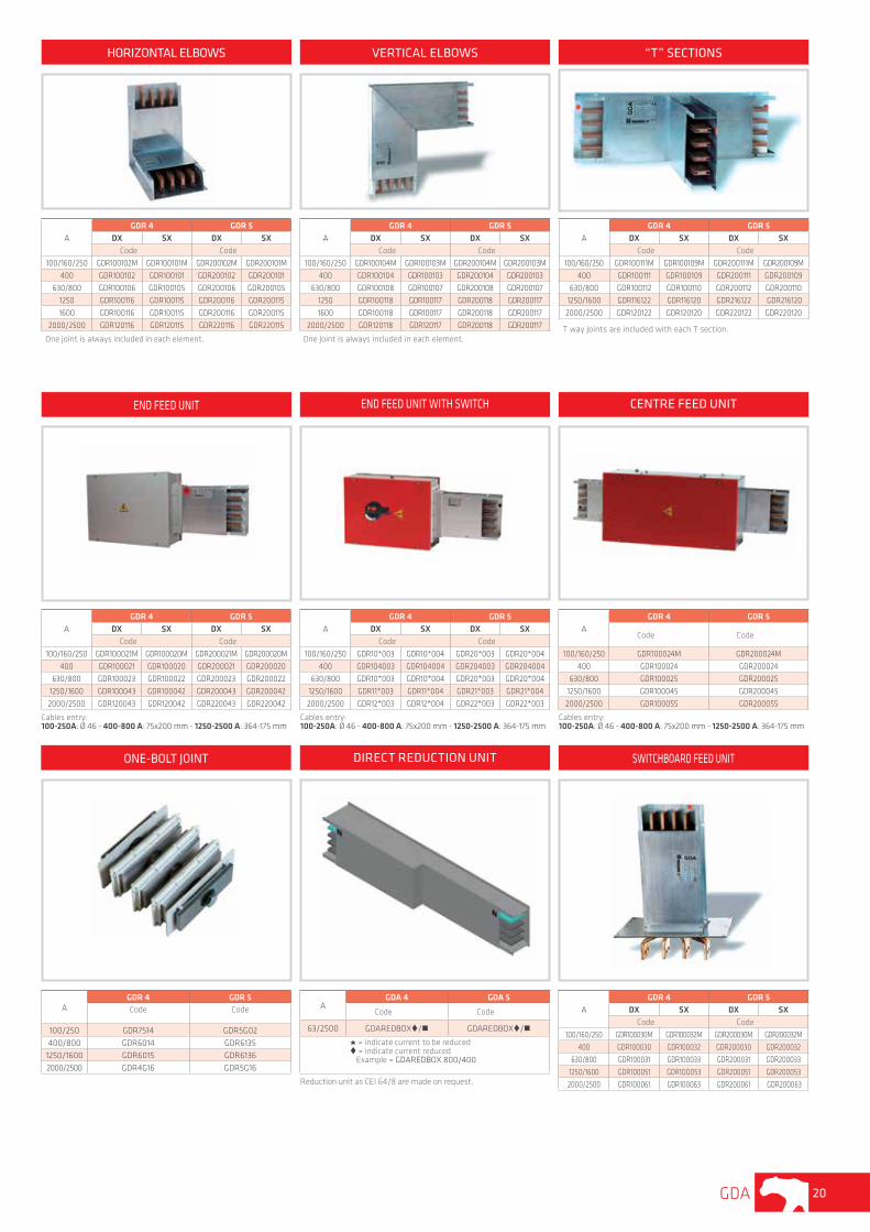
A
GDR 4 GDR 5DX SX DX SX
Code Code
100/160/250 GDR100111M GDR100109M GDR200111M GDR200109M
400 GDR100111 GDR100109 GDR200111 GDR200109
630/800 GDR100112 GDR100110 GDR200112 GDR200110
1250/1600 GDR116122 GDR116120 GDR216122 GDR216120
2000/2500 GDR120122 GDR120120 GDR220122 GDR220120
T way joints are included with each T section.
A
GDR 4 GDR 5DX SX DX SX
Code Code
100/160/250 GDR100030M GDR100032M GDR200030M GDR200032M
400 GDR100030 GDR100032 GDR200030 GDR200032
630/800 GDR100031 GDR100033 GDR200031 GDR200033
1250/1600 GDR100051 GDR1OO053 GDR200051 GDR200053
2000/2500 GDR100061 GDR100063 GDR200061 GDR200063
AGDR 4 GDR 5Code Code
100/250 GDR7514 GDR5G02
400/800 GDR6014 GDR6135
1250/1600 GDR6015 GDR6136
2000/2500 GDR4G16 GDR5G16
“T” SECTIONS
SWITCHBOARD FEED UNITONE-BOLT JOINT
A
GDR 4 GDR 5DX SX DX SX
Code Code
100/160/250 GDR100102M GDR100101M GDR200102M GDR200101M
400 GDR100102 GDR100101 GDR200102 GDR200101
630/800 GDR100106 GDR100105 GDR200106 GDR200105
1250 GDR100116 GDR100115 GDR200116 GDR200115
1600 GDR100116 GDR100115 GDR200116 GDR200115
2000/2500 GDR120116 GDR120115 GDR220116 GDR220115
One joint is always included in each element.
HORIZONTAL ELBOWS VERTICAL ELBOWS
A
GDR 4 GDR 5DX SX DX SX
Code Code
100/160/250 GDR100021M GDR100020M GDR200021M GDR200020M
400 GDR100021 GDR100020 GDR200021 GDR200020
630/800 GDR100023 GDR100022 GDR200023 GDR200022
1250/1600 GDR100043 GDR100042 GDR200043 GDR200042
2000/2500 GDR120043 GDR120042 GDR220043 GDR220042
Cables entry:100-250A: Ø 46 - 400-800 A: 75x200 mm - 1250-2500 A: 364-175 mm
END FEED UNIT END FEED UNIT WITH SWITCH CENTRE FEED UNIT
DIRECT REDUCTION UNIT
A
GDR 4 GDR 5DX SX DX SX
Code Code
100/160/250 GDR100104M GDR100103M GDR200104M GDR200103M
400 GDR100104 GDR100103 GDR200104 GDR200103
630/800 GDR100108 GDR100107 GDR200108 GDR200107
1250 GDR100118 GDR100117 GDR200118 GDR200117
1600 GDR100118 GDR100117 GDR200118 GDR200117
2000/2500 GDR120118 GDR120117 GDR200118 GDR200117
One joint is always included in each element.
A
GDR 4 GDR 5DX SX DX SX
Code Code
100/160/250 GDR10*003 GDR10*004 GDR20*003 GDR20*004
400 GDR104003 GDR104004 GDR204003 GDR204004
630/800 GDR10*003 GDR10*004 GDR20*003 GDR20*004
1250/1600 GDR11*003 GDR11*004 GDR21*003 GDR21*004
2000/2500 GDR12*003 GDR12*004 GDR22*003 GDR22*003
Cables entry: 100-250A: Ø 46 - 400-800 A: 75x200 mm - 1250-2500 A: 364-175 mm
A
GDR 4 GDR 5
Code Code
100/160/250 GDR100024M GDR200024M
400 GDR100024 GDR200024
630/800 GDR100025 GDR200025
1250/1600 GDR100045 GDR200045
2000/2500 GDR100055 GDR200055
Cables entry:100-250A: Ø 46 - 400-800 A: 75x200 mm - 1250-2500 A: 364-175 mm
AGDA 4 GDA 5
Code Code
63/2500 GDAREDBOX/n GDAREDBOX/n
= indicate current to be reduced = indicate current reduced
Example = GDAREDBOX 800/400
Reduction unit as CEI 64/8 are made on request.
GDA21
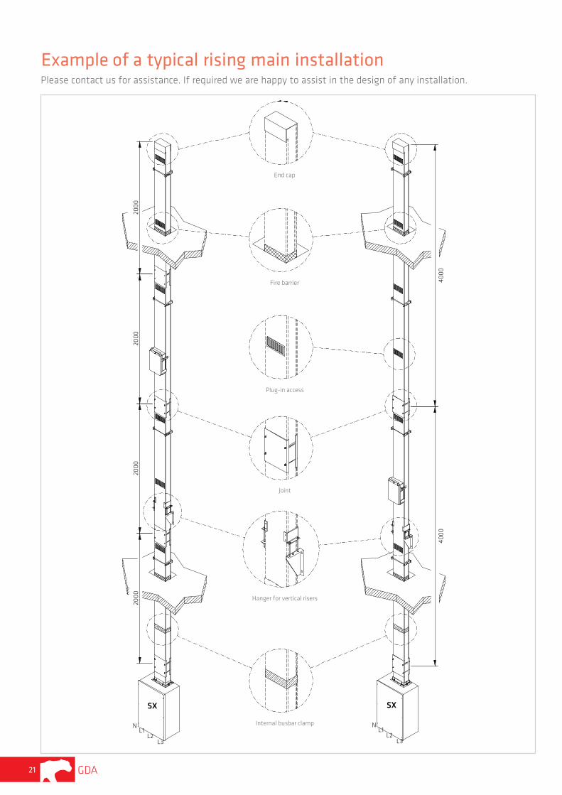
End cap
Fire barrier
Joint
Hanger for vertical risers
Internal busbar clamp
Plug-in access
2000
2000
2000
2000
4000
4000
SX
NL1
L2L3
SX
NL1
L2L3
Example of a typical rising main installationPlease contact us for assistance. If required we are happy to assist in the design of any installation.
GDA 22
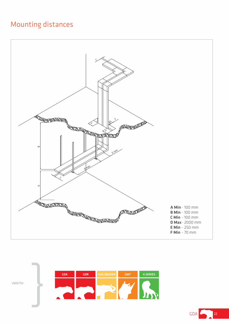
A Min - 100 mm B Min - 100 mm C Min - 100 mm D Max - 2000 mm E Min - 250 mm F Min - 70 mm
Mounting distances
Valid for:
GDA GDR ISOLSBARRA GMT K-SERIES
GDA23
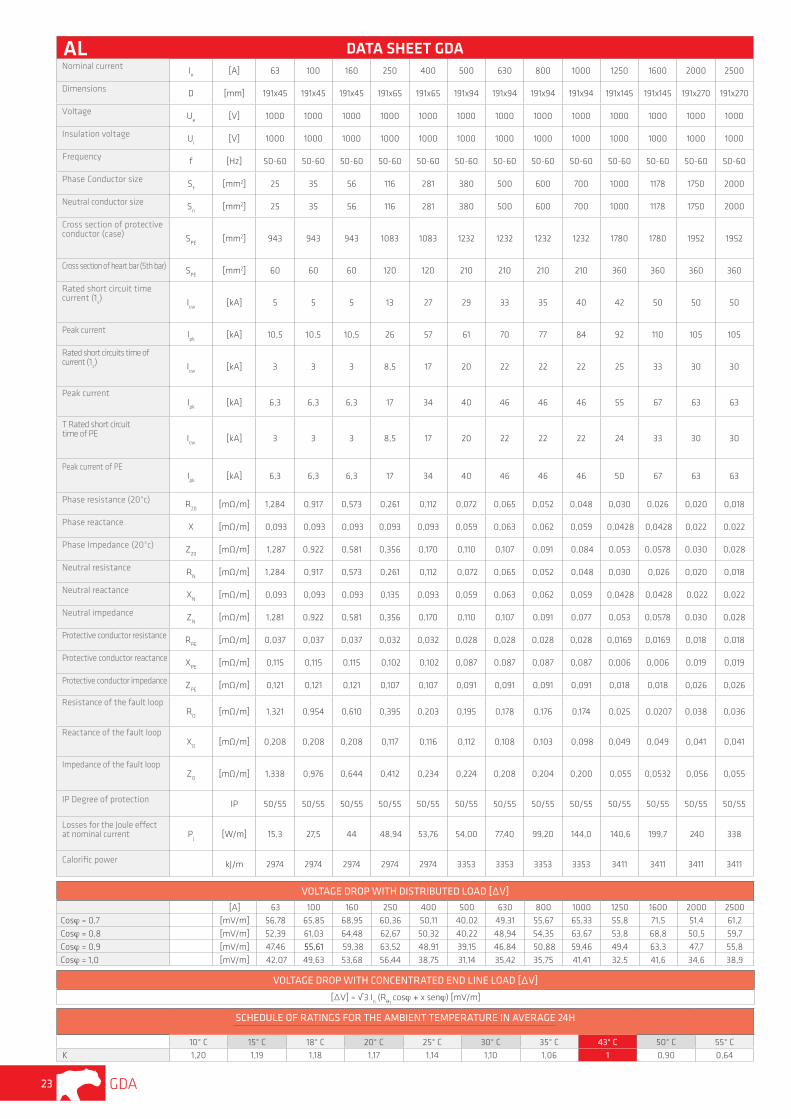
DATA SHEET GDANominal current I
n[A] 63 100 160 250 400 500 630 800 1000 1250 1600 2000 2500
Dimensions D [mm] 191x45 191x45 191x45 191x65 191x65 191x94 191x94 191x94 191x94 191x145 191x145 191x270 191x270
Voltage Ue
[V] 1000 1000 1000 1000 1000 1000 1000 1000 1000 1000 1000 1000 1000
Insulation voltage Ui
[V] 1000 1000 1000 1000 1000 1000 1000 1000 1000 1000 1000 1000 1000
Frequency f [Hz] 50-60 50-60 50-60 50-60 50-60 50-60 50-60 50-60 50-60 50-60 50-60 50-60 50-60
Phase Conductor size Sf
[mm2] 25 35 56 116 281 380 500 600 700 1000 1178 1750 2000
Neutral conductor size Sn
[mm2] 25 35 56 116 281 380 500 600 700 1000 1178 1750 2000
Cross section of protectiveconductor (case) S
PE[mm2] 943 943 943 1083 1083 1232 1232 1232 1232 1780 1780 1952 1952
Cross section of heart bar (5th bar) SPE
[mm2] 60 60 60 120 120 210 210 210 210 360 360 360 360
Rated short circuit time current (1
s) I
cw[kA] 5 5 5 13 27 29 33 35 40 42 50 50 50
Peak current Ipk
[kA] 10,5 10,5 10,5 26 57 61 70 77 84 92 110 105 105
Rated short circuits time of current (1
s) I
cw[kA] 3 3 3 8,5 17 20 22 22 22 25 33 30 30
Peak currentIpk
[kA] 6,3 6,3 6,3 17 34 40 46 46 46 55 67 63 63
T Rated short circuittime of PE I
cw[kA] 3 3 3 8,5 17 20 22 22 22 24 33 30 30
Peak current of PEIpk
[kA] 6,3 6,3 6,3 17 34 40 46 46 46 50 67 63 63
Phase resistance (20°c) R20
[mΩ/m] 1,284 0,917 0,573 0,261 0,112 0,072 0,065 0,052 0,048 0,030 0,026 0,020 0,018
Phase reactance X [mΩ/m] 0,093 0,093 0,093 0,093 0,093 0,059 0,063 0,062 0,059 0,0428 0,0428 0,022 0,022
Phase Impedance (20°c) Z20
[mΩ/m] 1,287 0,922 0,581 0,356 0,170 0,110 0,107 0,091 0,084 0,053 0,0578 0,030 0,028
Neutral resistance RN
[mΩ/m] 1,284 0,917 0,573 0,261 0,112 0,072 0,065 0,052 0,048 0,030 0,026 0,020 0,018
Neutral reactance XN
[mΩ/m] 0,093 0,093 0,093 0,135 0,093 0,059 0,063 0,062 0,059 0,0428 0,0428 0,022 0,022
Neutral impedance ZN
[mΩ/m] 1,281 0,922 0,581 0,356 0,170 0,110 0,107 0,091 0,077 0,053 0,0578 0,030 0,028
Protective conductor resistance RPE
[mΩ/m] 0,037 0,037 0,037 0,032 0,032 0,028 0,028 0,028 0,028 0,0169 0,0169 0,018 0,018
Protective conductor reactance XPE
[mΩ/m] 0,115 0,115 0,115 0,102 0,102 0,087 0,087 0,087 0,087 0,006 0,006 0,019 0,019
Protective conductor impedance ZPE
[mΩ/m] 0,121 0,121 0,121 0,107 0,107 0,091 0,091 0,091 0,091 0,018 0,018 0,026 0,026
Resistance of the fault loopR
O[mΩ/m] 1,321 0,954 0,610 0,395 0,203 0,195 0,178 0,176 0,174 0,025 0,0207 0,038 0,036
Reactance of the fault loopX
O[mΩ/m] 0,208 0,208 0,208 0,117 0,116 0,112 0,108 0,103 0,098 0,049 0,049 0,041 0,041
Impedance of the fault loopZ
O[mΩ/m] 1,338 0,976 0,644 0,412 0,234 0,224 0,208 0,204 0,200 0,055 0,0532 0,056 0,055
IP Degree of protection IP 50/55 50/55 50/55 50/55 50/55 50/55 50/55 50/55 50/55 50/55 50/55 50/55 50/55
Losses for the Joule effectat nominal current P
j[W/m] 15,3 27,5 44 48,94 53,76 54,00 77,40 99,20 144,0 140,6 199,7 240 338
Calorific power kJ/m 2974 2974 2974 2974 2974 3353 3353 3353 3353 3411 3411 3411 3411
VOLTAGE DROP WITH DISTRIBUTED LOAD [∆V]
[A] 63 100 160 250 400 500 630 800 1000 1250 1600 2000 2500
Cosϕ = 0,7 [mV/m] 56,78 65,85 68,95 60,36 50,11 40,02 49,31 55,67 65,33 55,8 71,5 51,4 61,2
Cosϕ = 0,8 [mV/m] 52,39 61,03 64,48 62,67 50,32 40,22 48,94 54,35 63,67 53,8 68,8 50,5 59,7
Cosϕ = 0,9 [mV/m] 47,46 55,61 59,38 63,52 48,91 39,15 46,84 50,88 59,46 49,4 63,3 47,7 55,8
Cosϕ = 1,0 [mV/m] 42,07 49,63 53,68 56,44 38,75 31,14 35,42 35,75 41,41 32,5 41,6 34,6 38,9
SCHEDULE OF RATINGS FOR THE AMBIENT TEMPERATURE IN AVERAGE 24H
10° C 15° C 18° C 20° C 25° C 30° C 35° C 43° C 50° C 55° C
K 1,20 1,19 1,18 1,17 1,14 1,10 1,06 1 0,90 0,64
VOLTAGE DROP WITH CONCENTRATED END LINE LOAD [∆V]
[∆V] = √3 In (R
θ1 cosϕ + x senϕ) [mV/m]
AL
GDA 24
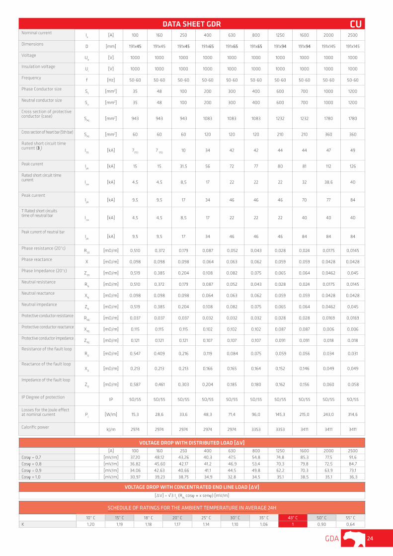
DATA SHEET GDRNominal current I
n[A] 100 160 250 400 630 800 1250 1600 2000 2500
Dimensions D [mm] 191x45 191x45 191x45 191x65 191x65 191x65 191x94 191x94 191x145 191x145
Voltage Ue
[V] 1000 1000 1000 1000 1000 1000 1000 1000 1000 1000
Insulation voltage Ui
[V] 1000 1000 1000 1000 1000 1000 1000 1000 1000 1000
Frequency f [Hz] 50-60 50-60 50-60 50-60 50-60 50-60 50-60 50-60 50-60 50-60
Phase Conductor size Sf
[mm2] 35 48 100 200 300 400 600 700 1000 1200
Neutral conductor size Sn
[mm2] 35 48 100 200 300 400 600 700 1000 1200
Cross section of protectiveconductor (case) S
PE[mm2] 943 943 943 1083 1083 1083 1232 1232 1780 1780
Cross section of heart bar (5th bar) SPE
[mm2] 60 60 60 120 120 120 210 210 360 360
Rated short circuit time current (3
s) I
3S[kA] 7
(1S)7
(1S)10 34 42 42 44 44 47 49
Peak current Ipk
[kA] 15 15 31,5 56 72 77 80 81 112 126
Rated short circuit timecurrent I
cw[kA] 4,5 4,5 8,5 17 22 22 22 32 38,6 40
Peak currentIpk
[kA] 9,5 9,5 17 34 46 46 46 70 77 84
T Rated short circuitstime of neutral bar I
cw[kA] 4,5 4,5 8,5 17 22 22 22 40 40 40
Peak current of neutral barIpk
[kA] 9,5 9,5 17 34 46 46 46 84 84 84
Phase resistance (20°c) R20
[mΩ/m] 0,510 0,372 0,179 0,087 0,052 0,043 0,028 0,024 0,0175 0,0145
Phase reactance X [mΩ/m] 0,098 0,098 0,098 0,064 0,063 0,062 0,059 0,059 0,0428 0,0428
Phase Impedance (20°c) Z20
[mΩ/m] 0,519 0,385 0,204 0,108 0,082 0,075 0,065 0,064 0,0462 0,045
Neutral resistance RN
[mΩ/m] 0,510 0,372 0,179 0,087 0,052 0,043 0,028 0,024 0,0175 0,0145
Neutral reactance XN
[mΩ/m] 0,098 0,098 0,098 0,064 0,063 0,062 0,059 0,059 0,0428 0,0428
Neutral impedance ZN
[mΩ/m] 0,519 0,385 0,204 0,108 0,082 0,075 0,065 0,064 0,0462 0,045
Protective conductor resistance RPE
[mΩ/m] 0,037 0,037 0,037 0,032 0,032 0,032 0,028 0,028 0,0169 0,0169
Protective conductor reactance XPE
[mΩ/m] 0,115 0,115 0,115 0,102 0,102 0,102 0,087 0,087 0,006 0,006
Protective conductor impedance ZPE
[mΩ/m] 0,121 0,121 0,121 0,107 0,107 0,107 0,091 0,091 0,018 0,018
Resistance of the fault loopR
O[mΩ/m] 0,547 0,409 0,216 0,119 0,084 0,075 0,059 0,056 0,034 0,031
Reactance of the fault loopX
O[mΩ/m] 0,213 0,213 0,213 0,166 0,165 0,164 0,152 0,146 0,049 0,049
Impedance of the fault loopZ
O[mΩ/m] 0,587 0,461 0,303 0,204 0,185 0,180 0,162 0,156 0,060 0,058
IP Degree of protection IP 5O/55 5O/55 5O/55 5O/55 5O/55 5O/55 5O/55 5O/55 5O/55 5O/55
Losses for the Joule effectat nominal current P
j[W/m] 15,3 28,6 33,6 48,3 71,4 96,0 145,3 215,0 243,0 314,6
Calorific power kJ/m 2974 2974 2974 2974 2974 3353 3353 3411 3411 3411
VOLTAGE DROP WITH DISTRIBUTED LOAD [∆V]
[A] 100 160 250 400 630 800 1250 1600 2000 2500
Cosϕ = 0,7 [mV/m] 37,20 48,12 43,26 40,3 47,5 54,8 74,8 85,3 77,5 91,6
Cosϕ = 0,8 [mV/m] 36,82 45,60 42,17 41,2 46,9 53,4 70,3 79,8 72,5 84,7
Cosϕ = 0,9 [mV/m] 34,06 42,63 40,66 41,1 44,5 49,8 62,2 70,3 63,9 73,1
Cosϕ = 1,0 [mV/m] 30,97 39,23 38,75 34,9 32,8 34,5 35,1 38,5 35,1 36,3
VOLTAGE DROP WITH CONCENTRATED END LINE LOAD [∆V]
[∆V] = √3 In (R
θ1 cosϕ + x senϕ) [mV/m]
SCHEDULE OF RATINGS FOR THE AMBIENT TEMPERATURE IN AVERAGE 24H
10° C 15° C 18° C 20° C 25° C 30° C 35° C 43° C 50° C 55° C
K 1,20 1,19 1,18 1,17 1,14 1,10 1,06 1 0,90 0,64
CU
GDA25
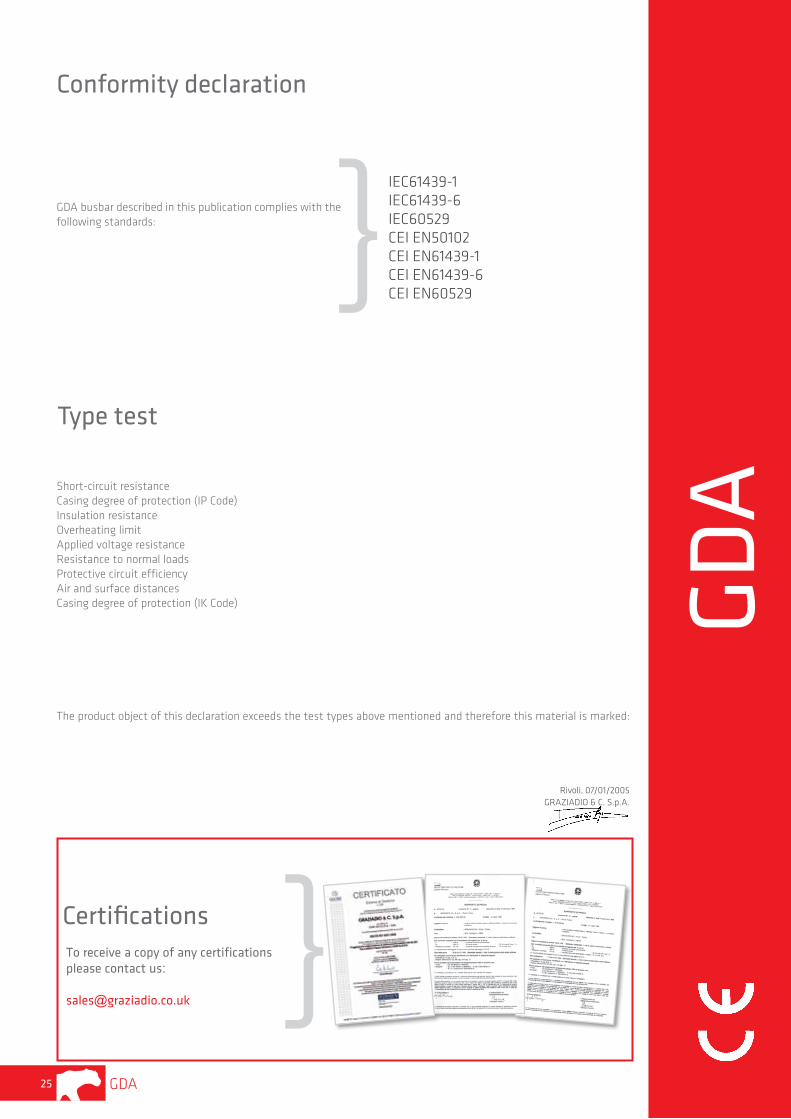
Conformity declaration
GDA busbar described in this publication complies with the following standards:
IEC61439-1IEC61439-6IEC60529CEI EN50102CEI EN61439-1CEI EN61439-6CEI EN60529
Type test
Short-circuit resistanceCasing degree of protection (IP Code)Insulation resistanceOverheating limitApplied voltage resistanceResistance to normal loadsProtective circuit efficiencyAir and surface distancesCasing degree of protection (IK Code)
Certifications
The product object of this declaration exceeds the test types above mentioned and therefore this material is marked:
Rivoli, 07/01/2005 GRAZIADIO & C. S.p.A.
GD
A
To receive a copy of any certificationsplease contact us:
GDA 55
Conformity declaration
GDR busbar described in this publication complies withthe following standards:
IEC61439-1IEC61439-6IEC60529CEI EN50102CEI EN61439-1CEI EN61439-6CEI EN60529
Type test
Short-circuit resistanceCasing degree of protection (IP Code)Insulation resistanceOverheating limitApplied voltage resistanceResistance to normal loadsProtective circuit efficiencyAir and surface distancesCasing degree of protection (IK Code)
The product object of this declaration exceeds the test types above mentioned and therefore this material is marked:
Rivoli, 07/01/2005GRAZIADIO & C. S.p.A.
CertificationsTo receive a copy of any certificationsplease contact us: