gcse physics exam doctor electricity – potential difference question 1 question 2 question 3...
TRANSCRIPT

GCSE Physics Exam Doctor
Electricity – Potential Difference
Question1
Question2
Question3
Question4
Question5
Question6

GCSE Physics Exam Doctor
Electricity – Potential Difference
Question 1

12v battery variable resistor A lamp fixed resistor R B V a) What is the sum of the readings of voltmeters V1 and V2?
V1 V2
b) What does your answer assume about the wire which connects the components?
(1 mark)
(2 marks)

c) If V2 reads 8v what is the potential difference across the variable resistor?
(1 mark)d) The fixed resistor R is replaced by one with only half as much resistance.Predict the reading on V2 and explain why this would happen.
(3 marks)
e) The resistance of the variable resistor is reduced until it is extremely small. Explain how this affects the reading on voltmeter V2.
(2 marks)
f) If the 12v battery were replaced by a 9v battery, what would be the potential difference between points A and B?
(1 mark)

12v battery variable resistor A lamp fixed resistor R B V a) What is the sum of the readings of voltmeters V1 and V2?
V1 V2
b) What does your answer assume about the wire which connects the components?
(1 mark)
(2 marks)
12 V
it is made of copper

c) If V2 reads 8v what is the potential difference across the variable resistor?
(1 mark)d) The fixed resistor R is replaced by one with only half as much resistance.Predict the reading on V2 and explain why this would happen.
(3 marks)
e) The resistance of the variable resistor is reduced until it is extremely small. Explain how this affects the reading on voltmeter V2.
(2 marks)
f) If the 12v battery were replaced by a 9v battery, what would be the potential difference between points A and B?
(1 mark)
6v
The reading would rise because it has less resistance
The reading would go down because it has too much current in it.
9v

12v battery variable resistor A lamp fixed resistor R B V a) What is the sum of the readings of voltmeters V1 and V2?
V1 V2
b) What does your answer assume about the wire which connects the components?
(1 mark)
(2 marks)
Mark scheme
12V 1MP
the wire has little or no resistance 1MP the wire has negligible ( zero) potential difference (PD) between its ends 1MP

c) If V2 reads 8v what is the potential difference across the variable resistor?
(1 mark)d) The fixed resistor R is replaced by one with only half as much resistance.Predict the reading on V2 and explain why this would happen.
(3 marks)
e) The resistance of the variable resistor is reduced until it is extremely small. Explain how this affects the reading on voltmeter V2.
(2 marks)
f) If the 12v battery were replaced by a 9v battery, what would be the potential difference between points A and B?
(1 mark)
Mark scheme
4v 1MP
Reading on V2 would fall. 1MP
lower resistance would cause a smaller PD across R 1MPtotal of PD must remain 12v 1MP
V2 would rise 1MP
because with low resistance the PD across the variable resistor would fall 1MP
9v 1MP

12v battery variable resistor A lamp fixed resistor R B V a) What is the sum of the readings of voltmeters V1 and V2?
V1 V2
b) What does your answer assume about the wire which connects the components?
(1 mark)
(2 marks)
12 V
it is made of copperThe wire may be made of copper but there is no mention of low resistance or low PD across it so no marks
13

c) If V2 reads 8v what is the potential difference across the variable resistor?
(1 mark)d) The fixed resistor R is replaced by one with only half as much resistance.Predict the reading on V2 and explain why this would happen.
(3 marks)
e) The resistance of the variable resistor is reduced until it is extremely small. Explain how this affects the reading on voltmeter V2.
(2 marks)
f) If the 12v battery were replaced by a 9v battery, what would be the potential difference between points A and B?
(1 mark)
6v
The reading would rise because it has less resistance
The reading would go down because it has too much current in it.
9v
No mark the PD is 12 - 8 = 4v
The reading on V2 would fall. One mark for mentioning less resistance.
Incorrect, the voltmeter reading rises so no mark. The low resistance leads to low PD across the variable resistor so higher PD across the lamp ( total still = 12v)
27

GCSE Physics Exam Doctor
Electricity – Potential Difference
Question 2

The diagram shows an electric blanket connected to the mains electricity. The switch S allows the blanket to be switched to high or low settings. When the switch is placed in position A, the current in the circuit is 0.3A
a) i) The resistance of the heating element is 600Calculate the voltage across the heating element in the blanket.
(3 marks)

ii) Calculate the power developed in the blanket when the switch is in position A.
(2 marks)
b) When the switch is moved to position B, will the temperature of the blanket increase or decrease? Explain your reasoning.
(2 marks)

The diagram shows an electric blanket connected to the mains electricity. The switch S allows the blanket to be switched to high or low settings. When the switch is placed in position A, the current in the circuit is 0.3A
a) i) The resistance of the heating element is 600Calculate the voltage across the heating element in the blanket.
(3 marks)
V = I x R = 0.3 x 600 = 180V

ii) Calculate the power developed in the blanket when the switch is in position A.
(2 marks)
b) When the switch is moved to position B, will the temperature of the blanket increase or decrease? Explain your reasoning.
(2 marks)
Power = V x I = 240 x 0.3 = 72W
The blanket will get hotter. The electricity is going straight to the blanket instead of through the 200W.

The diagram shows an electric blanket connected to the mains electricity. The switch S allows the blanket to be switched to high or low settings. When the switch is placed in position A, the current in the circuit is 0.3A
a) i) The resistance of the heating element is 600Calculate the voltage across the heating element in the blanket.
(3 marks)
Mark scheme
V = I x R V = 0.3 x 600 = 180V

ii) Calculate the power developed in the blanket when the switch is in position A.
(2 marks)
b) When the switch is moved to position B, will the temperature of the blanket increase or decrease? Explain your reasoning.
(2 marks)
Mark scheme
Power = V x I = 180V x 0.3A = 54W
Understanding that the whole 240V would now be across the blanket, giving greater power, or that the current through the blanket would be higher.

The diagram shows an electric blanket connected to the mains electricity. The switch S allows the blanket to be switched to high or low settings. When the switch is placed in position A, the current in the circuit is 0.3A
a) i) The resistance of the heating element is 600Calculate the voltage across the heating element in the blanket.
(3 marks)
V = I x R = 0.3 x 600 = 180VIt would have been equally correct to use the fact that voltage is in the ratio of the resistances i.e. (600/800) x 240V = 180V
33

ii) Calculate the power developed in the blanket when the switch is in position A.
(2 marks)
b) When the switch is moved to position B, will the temperature of the blanket increase or decrease? Explain your reasoning.
(2 marks)
Power = V x I = 240 x 0.3 = 72W
The blanket will get hotter. The electricity is going straight to the blanket instead of through the 20O Ohms.
Scores one for Power = V x I
240V is not the voltage across the blanket. The figure needed is that from part i) 180V. Power = V x I = 180V x 0.3A = 54W
P = I2 R is given at the front of the paper and would yield the correct result 0.3A x 0.3A x 600W = 54W
“Electricity” is too imprecise. Needs to show understanding that the whole 240V would now be across the blanket, giving greater power, or that the current through the blanket would be higher, or that energy is not being wasted in the resistor.
24

GCSE Physics Exam Doctor
Electricity – Potential Difference
Question 3

The circuit shows 2 bulbs connected in series across a 12V supply.
a) i) Lamp A is marked 3V, 0.25A. What does this tell you?
(2 marks)

ii) Lamp B is marked 9V, 0.25A. When the lamps are connected as shown, what will voltmeter V1 read?
(1 mark)
iii) What will voltmeter V2 read?
(1 mark)
b) i) Calculate the resistance of lamp A.
(3 marks)
ii) What is the total resistance in the circuit?
(2 marks)

The circuit shows 2 bulbs connected in series across a 12V supply.
a) i) Lamp A is marked 3V, 0.25A. What does this tell you?
(2 marks)
It tells me that the lamp uses 3V of electricity and needs a current of 0.25A

ii) Lamp B is marked 9V, 0.25A. When the lamps are connected as shown, what will voltmeter V1 read?
(1 mark)
iii) What will voltmeter V2 read?
(1 mark)
b) i) Calculate the resistance of lamp A.
(3 marks)
ii) What is the total resistance in the circuit?
(2 marks)
V1 will read 6V.
The voltage V2 will also be 6V, since the voltage is split between the lamps.
V = I R 3 = 0.25 R R = 12
9 = 0.25 R R = 36 total = 48

The circuit shows 2 bulbs connected in series across a 12V supply.
a) i) Lamp A is marked 3V, 0.25A. What does this tell you?
(2 marks)
Mark scheme
The P.D. across a lamp in series with another lamp depends on the resistance of the 2 lamps. The voltage across each will be in the ratio of the resistances. The marking on the lamp tells you what voltage it was designed to be operated on, and if it is operated at that voltage, the current through it will be 0.25A.

ii) Lamp B is marked 9V, 0.25A. When the lamps are connected as shown, what will voltmeter V1 read?
(1 mark)
iii) What will voltmeter V2 read?
(1 mark)
b) i) Calculate the resistance of lamp A.
(3 marks)
ii) What is the total resistance in the circuit?
(2 marks)
Mark scheme
The voltage V1 will be 3V .
V2 actually reads 9V (12V minus 3V)
V = I R R = V/I = 3/0.25 =12 Ohms
For lamp B R = V/I = 9/0.25 =36 Ohms 12+36= 48 Ohms

The circuit shows 2 bulbs connected in series across a 12V supply.
a) i) Lamp A is marked 3V, 0.25A. What does this tell you?
(2 marks)
It tells me that the lamp uses 3V of electricity and needs a current of 0.25A
This is a common misunderstanding. The P.D. across a lamp in series with another lamp depends on the resistance of the 2 lamps. The voltage across each will be in the ratio of the resistances. The marking on the lamp tells you what voltage it was designed to be operated on, and if it is operated at that voltage, the current through it will be 0.25A.
02

ii) Lamp B is marked 9V, 0.25A. When the lamps are connected as shown, what will voltmeter V1 read?
(1 mark)
iii) What will voltmeter V2 read?
(1 mark)
b) i) Calculate the resistance of lamp A.
(3 marks)
ii) What is the total resistance in the circuit?
(2 marks)
V1 will read 6V.
The voltage V2 will also be 6V, since the voltage is split between the lamps.
V = I R 3 = 0.25 R R = 12
9 = 0.25 R R = 36 total = 48
Another common mistake, to assume that the lamps are identical. These are not. The voltage V1 will be 3V .
V2 actually reads 9V (12V minus 3V)This mark could have been awarded as e.c.f if the pupil had said “ V2 will be 12V minus 6V, but “the voltage being split” shows misunderstanding.
57

GCSE Physics Exam Doctor
Electricity – Potential Difference
Question 4

The diagram shows two lamps connected in series. Lamp A is marked 2.5V 0.3A. Lamp B is a normal 60W mains lamp.
a) i) Calculate the resistance of lamp A.
(3 marks)

ii) Mains voltage is 240V. What current would the mains lamp take if it were operated normally in a mains circuit?
(2 marks)
iii) Calculate the resistance of lamp B.
(2 marks)
b) i) If lamp A were connected in a mains circuit on its own, what would you expect to happen?
(1 mark)
ii) When lamp A is connected with the mains lamp as shown, what is the Potential Difference across lamp A?
(2 marks)

The diagram shows two lamps connected in series. Lamp A is marked 2.5V 0.3A. Lamp B is a normal 60W mains lamp.
a) i) Calculate the resistance of lamp A.
(3 marks)
V = I R 2.5 = 0.3 R R = 2.5/0.3 = 8.33

ii) Mains voltage is 240V. What current would the mains lamp take if it were operated normally in a mains circuit?
(2 marks)
iii) Calculate the resistance of lamp B.
(2 marks)
b) i) If lamp A were connected in a mains circuit on its own, what would you expect to happen?
(1 mark)
ii) When lamp A is connected with the mains lamp as shown, what is the Potential Difference across lamp A?
(2 marks)
I = 240/60 = 4A
240V same as across lamp B
V = I R 240/ 4 = 60
I would expect it to explode.

The diagram shows two lamps connected in series. Lamp A is marked 2.5V 0.3A. Lamp B is a normal 60W mains lamp.
a) i) Calculate the resistance of lamp A.
(3 marks)
Mark scheme
V = I R 2.5 = 0.3 R R = 2.5/0.3 = 8.33

ii) Mains voltage is 240V. What current would the mains lamp take if it were operated normally in a mains circuit?
(2 marks)
iii) Calculate the resistance of lamp B.
(2 marks)
b) i) If lamp A were connected in a mains circuit on its own, what would you expect to happen?
(1 mark)
ii) When lamp A is connected with the mains lamp as shown, what is the Potential Difference across lamp A?
(2 marks)
Mark scheme
I = 60W/240V = 0.25A
R = 240V / 0.25A = 960Ω
Lamp fails
The P.Ds are in the ratio of the resistances, so P.D. across lamp A is (8.33/968.33) x 240V = 2.06V

The diagram shows two lamps connected in series. Lamp A is marked 2.5V 0.3A. Lamp B is a normal 60W mains lamp.
a) i) Calculate the resistance of lamp A.
(3 marks)
V = I R 2.5 = 0.3 R R = 2.5/0.3 = 8.33
33

ii) Mains voltage is 240V. What current would the mains lamp take if it were operated normally in a mains circuit?
(2 marks)
iii) Calculate the resistance of lamp B.
(2 marks)
b) i) If lamp A were connected in a mains circuit on its own, what would you expect to happen?
(1 mark)
ii) When lamp A is connected with the mains lamp as shown, what is the Potential Difference across lamp A?
(2 marks)
I = 240/60 = 4A
240V same as across lamp B
It is quite common for pupils who are otherwise quite competent at calculation to get this one upside-down. I = 60W/240V = 0.25A
e.c.f The answer is incorrect, but the calculation is correctly done. The error has been penalised in part ii).R = 240V / 0.25A = 960Ω
V = I R 240/ 4 = 60
Although this is a little extreme, it is sufficient for 1 mark. I would expect it to explode.
The P.Ds are in the ratio of the resistances, so P.D. across lamp A is (8.33/968.33) x 240V = 2.06V
GCSE Physics Exam Doctor
Electricity – Potential Difference
Question 5

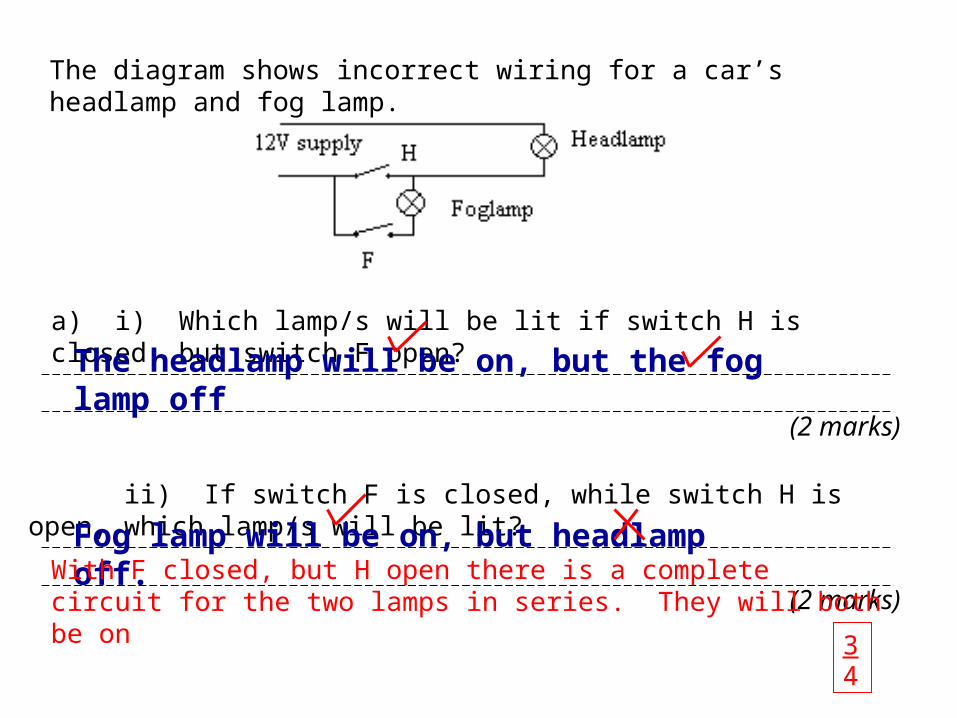
The diagram shows incorrect wiring for a car’s headlamp and fog lamp.
a) i) Which lamp/s will be lit if switch H is closed, but switch F open?
(2 marks)
ii) If switch F is closed, while switch H is open, which lamp/s will be lit?
(2 marks)

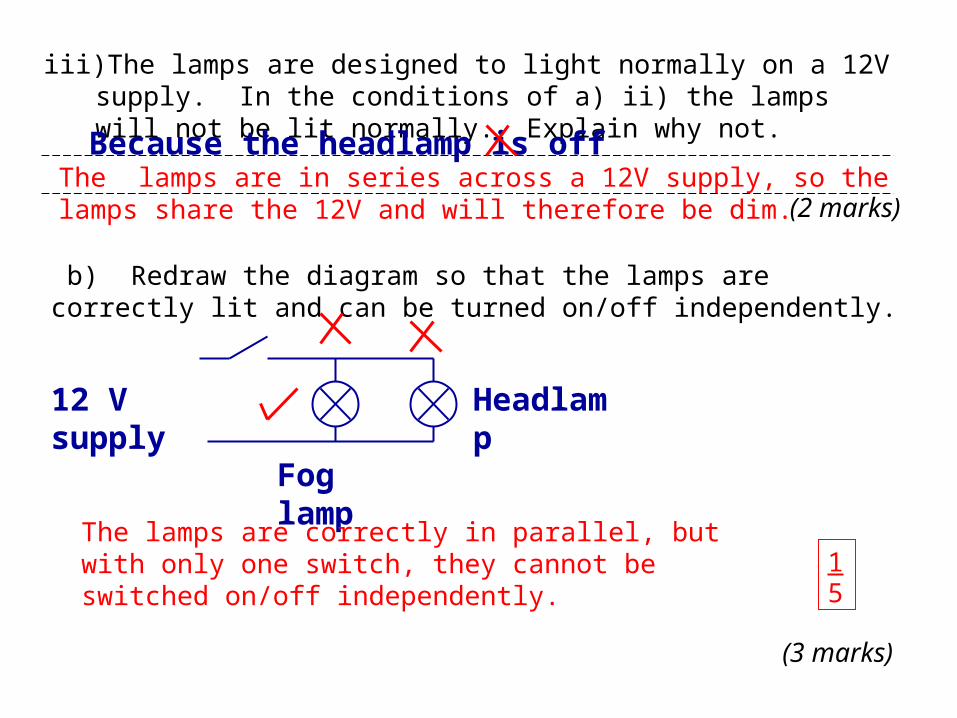
iii) The lamps are designed to light normally on a 12V supply. In the conditions of a) ii) the lamps will not be lit normally. Explain why not.
(2 marks)
b) Redraw the diagram so that the lamps are correctly lit and can be turned on/off independently.
(3 marks)

The diagram shows incorrect wiring for a car’s headlamp and fog lamp.
a) i) Which lamp/s will be lit if switch H is closed, but switch F open?
(2 marks)
ii) If switch F is closed, while switch H is open, which lamp/s will be lit?
(2 marks)
The headlamp will be on, but the fog lamp off
Fog lamp will be on, but headlamp off.

iii) The lamps are designed to light normally on a 12V supply. In the conditions of a) ii) the lamps will not be lit normally. Explain why not.
(2 marks)
b) Redraw the diagram so that the lamps are correctly lit and can be turned on/off independently.
(3 marks)
Because the headlamp is off
12 V supply
Fog lamp
Headlamp

The diagram shows incorrect wiring for a car’s headlamp and fog lamp.
a) i) Which lamp/s will be lit if switch H is closed, but switch F open?
(2 marks)
ii) If switch F is closed, while switch H is open, which lamp/s will be lit?
(2 marks)
Mark scheme
The headlamp will be on, but the fog lamp off
With F closed, but H open there is a complete circuit for the two lamps in series. They will both be on.

iii) The lamps are designed to light normally on a 12V supply. In the conditions of a) ii) the lamps will not be lit normally. Explain why not.
(2 marks)
b) Redraw the diagram so that the lamps are correctly lit and can be turned on/off independently.
(3 marks)
Mark scheme
The lamps are in series across a 12V supply, so the lamps share the 12V and will therefore be dim.
The diagram shows incorrect wiring for a car’s headlamp and fog lamp.
a) i) Which lamp/s will be lit if switch H is closed, but switch F open?
(2 marks)
ii) If switch F is closed, while switch H is open, which lamp/s will be lit?
(2 marks)
The headlamp will be on, but the fog lamp off
Fog lamp will be on, but headlamp off.With F closed, but H open there is a complete circuit for the two lamps in
series. They will both be on
34
iii) The lamps are designed to light normally on a 12V supply. In the conditions of a) ii) the lamps will not be lit normally. Explain why not.
(2 marks)
b) Redraw the diagram so that the lamps are correctly lit and can be turned on/off independently.
(3 marks)
Because the headlamp is off
12 V supply
Fog lamp
Headlamp
The lamps are in series across a 12V supply, so the lamps share the 12V and will therefore be dim.
The lamps are correctly in parallel, but with only one switch, they cannot be switched on/off independently. 1
5

GCSE Physics Exam Doctor
Electricity – Potential Difference
Question 6

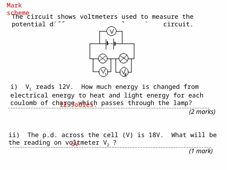
The circuit shows voltmeters used to measure the potential differences across lamps in a circuit.
i) V1 reads 12V. How much energy is changed from electrical energy to heat and light energy for each coulomb of charge which passes through the lamp? (2 marks)
ii) The p.d. across the cell (V) is 18V. What will be the reading on voltmeter V2 ?
(1 mark)

iii) How much energy is converted into electrical energy in the cell for each coulomb of charge which is drawn from the cell?
(2 marks)
iv) Are the lamps identical? Explain your answer.
(3 marks)

The circuit shows voltmeters used to measure the potential differences across lamps in a circuit.
i) V1 reads 12V. How much energy is changed from electrical energy to heat and light energy for each coulomb of charge which passes through the lamp? (2 marks)
ii) The p.d. across the cell (V) is 18V. What will be the reading on voltmeter V2 ?
(1 mark)
12V
6V

iii) How much energy is converted into electrical energy in the cell for each coulomb of charge which is drawn from the cell?
(2 marks)
iv) Are the lamps identical? Explain your answer.
(3 marks)
18V
Yes the symbol shows they are the same.. But the voltage is used before the second one can get it.
The circuit shows voltmeters used to measure the potential differences across lamps in a circuit.
i) V1 reads 12V. How much energy is changed from electrical energy to heat and light energy for each coulomb of charge which passes through the lamp? (2 marks)
ii) The p.d. across the cell (V) is 18V. What will be the reading on voltmeter V2 ?
(1 mark)
Mark scheme
12 Joules.
6V

iii) How much energy is converted into electrical energy in the cell for each coulomb of charge which is drawn from the cell?
(2 marks)
iv) Are the lamps identical? Explain your answer.
(3 marks)
Mark scheme
18 Joules.
No. The lamps have different resistances and the p.d.s across the lamps are in the ratios of the resistances.

The circuit shows voltmeters used to measure the potential differences across lamps in a circuit.
i) V1 reads 12V. How much energy is changed from electrical energy to heat and light energy for each coulomb of charge which passes through the lamp? (2 marks)
ii) The p.d. across the cell (V) is 18V. What will be the reading on voltmeter V2 ?
(1 mark)
12V
6V
The unit for energy is Joules. A Volt is the energy transferred in Joules for each coulomb of charge which passes.
23

iii) How much energy is converted into electrical energy in the cell for each coulomb of charge which is drawn from the cell?
(2 marks)
iv) Are the lamps identical? Explain your answer.
(3 marks)
18V
Yes the symbol shows they are the same.. But the voltage is used before the second one can get it.
The same mistake with units as before, but since it has already been penalised, both marks awarded.
Shows no understanding of the concept of potential difference in a series circuit. The lamps have different resistances and the p.d.s across the lamps are in the ratios of the resistances. 2
5
GCSE Physics Exam Doctor
Electricity – Potential Difference
End of questions