fundamentals of streaming media systems · chapter 1 fundamentals of streaming media systems...
TRANSCRIPT

Chapter 1
FUNDAMENTALS OFSTREAMING MEDIASYSTEMS
Multimedia (MM) systems utilize audio and visual information, such asvideo, audio, text, graphics, still images, and animations to provide effec-tive means for communication. These systems utilize multi-human sensesin conveying information, and they play a major role in educational ap-plications (such as e-learning and distance learning), library informationsystems (such as digital library systems), entertainment systems (such asVideo-On-Demand and interactive TV), communication systems (such asmobile phone multimedia messaging), military systems (such as AdvancedLeadership Training Simulation), etc. Due to the exponential improvementsof the past few years in solid state technology (i.e., processor and memory)as well as increased bandwidth and storage capacities of modern magneticdisk drives, it has been technically feasible to implement these systems inways we only could have dreamed about a decade ago.A challenging task when implementing MM systems is to support the
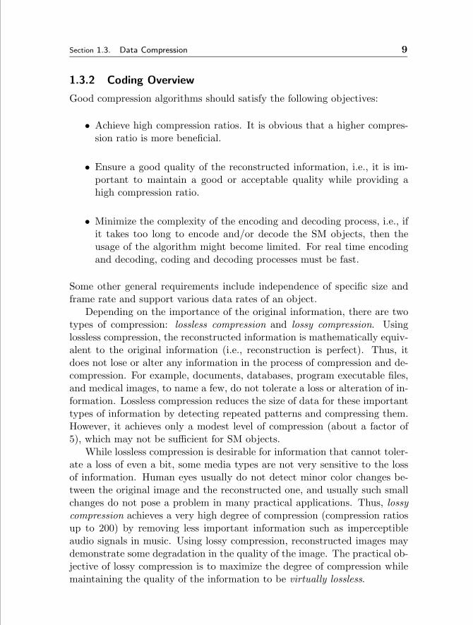
sustained bandwidth required to display Streaming Media (SM) objects, suchas video and audio objects. Unlike traditional data types, such as records,text and still images, SM objects are usually large in size. For example, a two-hour MPEG-2 encoded movie requires approximately 3.6 gigabytes (GByte)of storage (at a display rate of 4 megabits per second (Mb/s)). Figure 1.1compares the space requirements for ninety minute video clips encoded indifferent industry standard digital formats. Second, the isochronous natureof SM objects requires timely, real-time display of data blocks at a pre-specified rate. For example, the NTSC video standard requires that 30 videoframes per second be displayed to a viewer. Any deviation from this real-time requirement may result in undesirable artifacts, disruptions, and jitters,
1

2 Fundamentals of Streaming Media Systems Chapter 1
1
10
100
1000
Size [GB]
MPEG-2 DV 4:1:1 DV 4:2:2 Digi Beta D1 HDTV3 Mb/s 31 Mb/s 50 Mb/s 90 Mb/s 270 Mb/s 1.2 Gb/s
1.9
20.433.0
59.3
178.0
791.0
Figure 1.1. Storage requirements for a ninety minute video clip digitized indifferent industry standard encoding formats.
collectively termed hiccups.In the remainder of this chapter, the following topics are covered. First, in
Section 1.1, we introduce different display paradigms for SM objects. Next,in Section 1.2, we consider the overall SM system architecture. After that, inSection 1.3, we briefly overview data compression techniques. Subsequently,in Section 1.4, we describe a number of networking protocols that ensurereal-time streaming over the Internet. Finally, in Section 1.5, we present anoutline for the entire textbook.
1.1 Introduction to Streaming Media Display
Many applications that traditionally were the domain of analog audio andvideo are evolving to utilize digital audio and video. For example, satellitebroadcast networks, such as DirectTVTM, were designed from the groundup with a completely digital infrastructure. The proliferation of digital au-dio and video have been facilitated by the wide acceptance of standards forcompression and file formats. Consumer electronics are also adopting thesestandards in products such as the digital versatile disk (DVD1 and digital
1DVD is a standard for optical discs that feature the same form-factor as CD-ROMsbut holds 4.7 GByte of data or more.

Section 1.1. Introduction to Streaming Media Display 3
Local
Streaming
Local
Streaming
Store-and-
Display
Remote
Streaming
Local Remote
None-
Streaming
Streaming
Location of the SM Objects
Str
eam
ing C
apab
ilit
ies
of
the
Ser
ver
an
d t
he
Net
wo
rk
Progressive
Download
Figure 1.2. SM Display Paradigms.
VHS2 (D-VHS)). Furthermore, increased network capacity for local area net-works (LAN) and advanced streaming protocols (e.g., RTSP3) allow remoteviewing of SM clips.There are a number of possible display paradigms for SM objects, as
shown in Figure 1.2. These display paradigms are defined according to:
1. The location of the SM object (local vs. remote), and
2. The capabilities of the network and the servers (none-streaming vs.streaming).
SM objects can either be displayed from a local machine (i.e., local stream-ing) or from a remote server. In the former approach, the SM objects areavailable locally in their entirety (e.g., stored on a hard disk, or available onDVDs and/or CD-ROMs). When the user requests the display of an object,the data blocks are retrieved from the local storage, passed to the video-card/graphics-card for decoding, and subsequently displayed to the user.Modern personal computers (PCs) and consumer electronic devices (suchas Sony’s PlayStationTM and Microsoft’s XboxTM) can display a single SMobject without much difficulty. Local streaming does not require any guar-antees from the remote servers and the network (for obvious reasons), andhence, it occupies the upper and lower left quadrants of Figure 1.2.
2Video Home System: a half-inch video cassette format.3The Real Time Streaming Protocol is an Internet Engineering Task Force (IETF)
proposed standard for control of SM on the Internet.

4 Fundamentals of Streaming Media Systems Chapter 1
When the user requests the display of an object that resides on a remoteserver, the data blocks are retrieved from the remote server over a network(e.g., the Internet or a corporate intranet), and passed to the client fordisplay. Depending on the capabilities of the server and the network, thereare two alternative display paradigms: 1) store-and-display paradigm, and2) remote streaming paradigm. With the store-and-display paradigm, theSM objects are first downloaded in their entirety from a remote server to alocal storage before initiating the display process (which is similar to localstreaming). This paradigm is favored when the server and/or the networkcannot guarantee the isochronous nature of SM objects (upper right quadrantof Figure 1.2). With the remote streaming paradigm, the data blocks areretrieved from the remote server over a network and processed by the clientas soon as they are received; data blocks are not written to the local storage(although they might be buffered). This paradigm is possible only whenboth the server and the network can guarantee the isochronous nature ofthe SM object (lower right quadrant of Figure 1.2). In the remainder of thisbook, we will be referring to remote streaming as streaming.There are several advantages of streaming paradigm versus store-and-
display paradigm:
1. No waiting for downloads (well, not much waiting).
2. No physical copies of the content are stored locally. reducing the pos-sibility of copyright violations (if any).
3. No storage (or limited storage) requirements at the client side.
4. Support of live events.
On the other hand, there are a number of limitations to the streamingparadigm:
1. It requires real-time guarantees from the server and the network.
2. Lost or damaged packets (blocks) or missed deadlines may cause ahiccup in the display of the SM object.
It is important to note that streaming is not a progressive download, wherethe display starts as soon as enough of the data is buffered locally while theremainder of the file is being retrieved and stored on the local disk (i.e., atthe end of the display the entire SM object is stored locally). Progressivedownload can be identified as a special case of the steaming paradigm (if the

Section 1.2. Streaming Media System Architecture 5
system can guarantee the hiccup-free display of the SM objects), or a specialcase of store-and-display paradigm.In this book, we focus on the design of Steaming Media Servers (SM
Servers) that guarantee the continuous display of SM objects, assuming thatthe network delivers the data blocks in a timely fashion. We ignore for themost part design issues related to SM encoding standards (such as MPEG4
standards) and SM networking5.
1.2 Streaming Media System Architecture
To support the streaming paradigm, servers and the network must guaranteethe continuous display of the SM object without disruptions (i.e., hiccups).To illustrate, assume a SM object X that consists of n equi-sized blocks: X0,X1, ..., Xn−1, and resides on a SM server, as shown in Figure 1.3. There aresome important observations when streaming this object:
1. The display time of each block is a function of the display requirementsof each object and the size of the block. For example, if the displayrequirement of the object X is 4 Mb/s and the size of each block,Xi, is 1 MByte, then the display time of each block, Xi, is 2 seconds.However, it is important to note that SM objects can be encoded usingeither constant bit-rate (CBR) or variable bit-rate (VBR) schemes. Asthe name implies, the consumption rate of a CBR media is constantover time, while VBR streams use variable rates to achieve maximumcompression. We will assume CBR media throughout the book toprovide a focused discussion, unless indicated otherwise.
2. The retrieval time of each block is a function of the transfer rate ofthe SM server, and it is primarily related to the speed of the storagesubsystem.
3. The delivery time of each block from the SM server to the displaystation is a function of the network speed, traffic, and protocol used.
Assume that a user requests the display of object X from the SM server,as depicted in Figure 1.3. Using the above information, the SM server sched-ules the retrieval of the blocks, while the network ensures the timely delivery
4Motion Picture Encoding Group (MPEG) (http://mpeg.telecomitalialab.com/) hasstandardized several audio and video compression formats, such as MPEG-1, MPEG-2,and MPEG-4.
5In this chapter, we present an overview of SM encoding standards and introduce anumber of networking technologies that make SM possible over the Internet.

6 Fundamentals of Streaming Media Systems Chapter 1
Network Decoder
Buffer
Display Station
X0X1
X2X3X4
SM Server
X0 X2X1
X3 X4 ….
Request display of SM object X
Figure 1.3. System Architecture.
SM Server
Retrieval TimeX0 X1 X2 X3
Network
Delivery TimeX0 X1 X2
time
Buffer
Delay TimeX0 X1
Display Time X0 X1 X2
Time Period hiccup
Buffer is empty
Figure 1.4. Timing of retrieval, delivery, and display of object X.
of these blocks to the display station. The SM server stages a block of X (sayXi) from the disk into main memory and initiates its delivery to the displaystation (via the network). The SM server schedules the retrieval and thedelivery of Xi+1 prior to the completion of the display of Xi. This ensures asmooth transition between the two blocks in support of continuous display.This process is repeated until all blocks of X have been retrieved, delivered,and displayed. The periodic nature of the data retrieval and display processgives rise to the definition of a time period (Tp): it denotes the time requiredto display one data block. Note that the display time of a block is in general

Section 1.2. Streaming Media System Architecture 7
significantly longer than its retrieval and delivery time from the SM server tothe display station. Thus, the SM server can be multiplexed among severaldisplays.The display station in turn might buffer enough data (i.e., blocks) in its
memory, such that any delays in data delivery due to network or SM serverdelays are tolerated6 (see Figure 1.3). To guarantee the continuous displayof object X without any hiccups, it is critical that prior to the completion ofthe display of block Xi, block Xi+1 is available in the buffer at the displaystation. For example, consider the retrieval times, delivery times, and thedisplay times shown in Figure 1.4. Block X1 is retrieved and delivered tothe display station, and the display station delays the display of the blockto reduce the probability of hiccups (e.g., due to network delays). For blockX1, the network delivers the block in a shorter time, and hence, the blockis buffered for a longer period of time. If the network delay becomes longerthan anticipated, as shown in Figure 1.4 for block X2, then the display ofthe object might suffer a hiccup. Conversely, if the delivery of the blocksbecomes faster than the display rate of the object, then the display station’sbuffer might overflow. In this case, the display station might have to either:1) discard blocks, or 2) send a signal to the SM server to slow down orto pause the retrieval. The former will cause retransmissions of the blocks(increasing the network traffic) and extra load on the SM server, or it mightcause hiccups in the display. The later will affect retrieval schedule at theSM server.Due to the size and the isochronous characteristic of SM objects, the
design of servers in support of SM has been different from that of conven-tional file servers and associated storage systems [175], [59]. The fundamen-tal functionality of SM servers is a hiccup-free display of SM. However, justsupporting a continuous display is not enough in the design of SM serversbecause many real applications, especially commercial ones such as movie-on-demand systems that concurrently service multiple users, require maximizingthe performance of servers for cost-effective solutions. Thus, the followingperformance metrics are important: 1) the number of simultaneous displaysthat can be supported by a SM server, i.e., throughput, and 2) the amountof time elapsed from when a display request arrives at the system until thetime the actual display is initiated by the system on behalf of this request,i.e., startup latency. Throughput, in general, is closely related to anotherimportant metric of SM servers, cost per stream. If a technique supports ahigher throughput with fixed resources than others, it provides for a more
6Note that network and SM server delays can either be deterministic or otherwise.

8 Fundamentals of Streaming Media Systems Chapter 1
cost-effective solution. Throughout this book, we compare alternative de-signs based on these metrics.
1.3 Data Compression
A ninety minute uncompressed video clip digitized in High Definition Televi-sion (HDTV) format at 1.2 gigabits per second (Gb/s) requires 791 GByte ofstorage. Even though modern storage devices, such as magnetic disk drives,provide large storage capacities, it might not be economical to store SM ob-jects uncompressed. Moreover, the data transfer rate of magnetic disks is nothigh enough to retrieve multiple high bit rate objects in real time. A moreserious problem arises when transferring a large number of SM objects overthe network. Even though network speeds are rapidly increasing, it is noteconomically feasible to handle the simultaneous display of a large numberof SM objects over existing networks.To resolve these problems and to efficiently handle large number of SM
objects, we need to compress these objects, where a smaller SM object re-quires less disk storage space and less network bandwidth. In the remainderof this section, we briefly overview data compression techniques.
1.3.1 Information vs. Data
Data is an individual fact or multiple facts, or a value, or a set of values. Forexample, a collection of digitally captured pixel values of an image is data.Information is data in a usable form, usually interpreted in a predefined way.For example, the content of an image is information. In general, informationis meaningful to us and it is stored and handled as data in computer systems.Thus, the main goal of compression techniques is to reduce the size of datawhile maintaining as much information as possible.A popular approach in multimedia data compression is perceptual coding
that hides errors where humans will not see or hear them. Based on thestudies of human hearing and vision to understand how we see/hear, per-ceptual coding exploits the limit of human perception. For example, humanaudio perception ranges between 20 Hz and 20 KHz but most voice soundsare in low frequencies (below 4 KHz). Thus, audio signals above 4 KHz areeliminated in telephone systems. Human visual perception is strongly influ-enced by edges and low frequency information such as big objects. Thus,many detailed patterns in an image can be ignored in the coding process.Perception coding takes advantage of this fact and encodes only those signalsthat will be perceived by humans, eliminating lots of imperceptible signals.
Section 1.3. Data Compression 9
1.3.2 Coding Overview
Good compression algorithms should satisfy the following objectives:
• Achieve high compression ratios. It is obvious that a higher compres-sion ratio is more beneficial.
• Ensure a good quality of the reconstructed information, i.e., it is im-portant to maintain a good or acceptable quality while providing ahigh compression ratio.
• Minimize the complexity of the encoding and decoding process, i.e., ifit takes too long to encode and/or decode the SM objects, then theusage of the algorithm might become limited. For real time encodingand decoding, coding and decoding processes must be fast.
Some other general requirements include independence of specific size andframe rate and support various data rates of an object.Depending on the importance of the original information, there are two
types of compression: lossless compression and lossy compression. Usinglossless compression, the reconstructed information is mathematically equiv-alent to the original information (i.e., reconstruction is perfect). Thus, itdoes not lose or alter any information in the process of compression and de-compression. For example, documents, databases, program executable files,and medical images, to name a few, do not tolerate a loss or alteration of in-formation. Lossless compression reduces the size of data for these importanttypes of information by detecting repeated patterns and compressing them.However, it achieves only a modest level of compression (about a factor of5), which may not be sufficient for SM objects.While lossless compression is desirable for information that cannot toler-
ate a loss of even a bit, some media types are not very sensitive to the lossof information. Human eyes usually do not detect minor color changes be-tween the original image and the reconstructed one, and usually such smallchanges do not pose a problem in many practical applications. Thus, lossycompression achieves a very high degree of compression (compression ratiosup to 200) by removing less important information such as imperceptibleaudio signals in music. Using lossy compression, reconstructed images maydemonstrate some degradation in the quality of the image. The practical ob-jective of lossy compression is to maximize the degree of compression whilemaintaining the quality of the information to be virtually lossless.

10 Fundamentals of Streaming Media Systems Chapter 1
Entropy and Source Encoding
Entropy is a measure of amount of information. If N states are possi-ble, each characterized by a probability pi, with
∑Ni=1 pi = 1, then S =
−∑Ni=1 pilog2pi is the entropy which is the lowest bound on the number
of bits needed to describe all parts of the system. It corresponds to theinformation content of the system. For example, when there are only twosymbols, S1 (0.9) and S2 (0.1), the entropy is 0.9log20.9− 0.1log20.1 = 0.47.Another typical example is as follows. In an image with uniform distributionof gray-level intensity, i.e., pi = 1/256, the number of bits needed to codeeach gray level is 8 bits. Thus, the entropy of this image is 8.
Entropy encoding ignores semantics of input data and compresses me-dia streams by regarding them as sequences of bits. Run-length encodingand Huffman encoding are popular entropy encoding schemes. On the con-trary, source encoding optimizes the compression ratio by considering media-specific characteristics. It is also called sematic-based coding. Many advancedschemes such as DPCM, DCT, FFT, and Wavelet fall into this category. Inreality, most practical compression algorithms employ a hybrid of the sourceand entropy coding such that a source encoding is applied at the early stageof compression and then an entropy encoding is applied to results in anattempt to further reduce the data size.
Run-length Encoding
This is one of the simplest compression techniques. It replaces consecutiveoccurrences of a symbol with the symbol followed by the number of times itis repeated. For example, the string, “a a a a a” can be represented by thefollowing two bytes, “5a”. The first byte shows the number of occurrencesof the character, and the second byte represents the character itself. Thisscheme is naturally lossless and its compression factor ranges from 1/2 to1/5 depending on the contents of objects. This scheme is most useful wheresymbols appear in long runs: e.g., for images that have areas where the pixelsall have the same value, cartoons for example. However, this may not beefficient for complex objects where adjacent symbols are all different.
Relative Encoding
This is a technique that attempts to improve efficiency by transmitting onlythe difference between each value and its predecessor. In an image, based onthe fact that neighboring pixels may be changing slowly in many cases, onecan digitize the value at a pixel by using the values of the neighboring pixelsand encode the difference between two. A differential PCM coder (DPCM)

Section 1.3. Data Compression 11
quantizes and transmits the difference, d(n) = x(n)x(n− 1). The advantageof using difference d(n) instead of the actual value x(n) is the reduced numberof bits to represent a sample. For example, the series of pixel values “60 105161 129 78”, can be represented by “60+45+56-32-51”. By reducing the sizeof each value (in the example, 6 bits are enough to represent the differencewhile 8 bits are required to represent the original values), assuming thedifference is far smaller than the original value, it can reduce the overall sizeof data. This scheme works well when the adjacent values are not greatlychanging, such as voice signals. Furthermore, the transmitter can predicteach value based on a mathematical model and transmit only the differencebetween the predicted and actual values, further reducing the size of requiredbits to represent a value (predictive coding).
Huffman Encoding
Huffman encoding is a popular compression technique that assigns variablelength codes to symbols, so that the most frequently occurring symbols havethe shortest codes. Thus, more frequently occurring values are assigned fewerbits exploiting the statistical distribution of the values within an object. Tocorrectly decompress the encoded data, encoder and decoder must share thesame codebook. Huffman coding is particularly effective where the dataare dominated by a small number of symbols. Suppose that one wants toencode a source of N = 8 symbols: a,b,c,d,e,f,g,h. The probabilities of thesesymbols are: P(a) = 0.01, P(b) = 0.02, P(c) = 0.05, P(d) = 0.09, P(e) =0.18, P(f) = 0.2, P(g) = 0.2, P(h) = 0.25. If we assign 3 bits per symbol(N = 23 = 8), the average length of the symbols is: L =
∑8i=1 3P (i) = 3
bits/symbol. The minimum average length we could ever achieve is equal tothe entropy (according to Shannon’s theorem): S = −
∑8i=1 P (i)log2P (i) =
2.5821 bits/symbol = 0.86× L.The Huffman code assignment procedure is based on a binary tree struc-
ture. This tree is developed by a sequence of pairing operations in which thetwo least probable symbols are joined at a node to form two branches of atree.
• Step 1. The list of probabilities of the source symbols are associatedwith the leaves of a binary tree.
• Step 2. Take the two smallest probabilities in the list and generate anintermediate node as their parent and label the branch from parent toone of the child nodes 1 and the branch from parent to the other child0.

12 Fundamentals of Streaming Media Systems Chapter 1
• Step 3. Replace the probabilities and associated nodes in the list bythe single new intermediate node with the sum of the two probabilities.If the list contains only one element, quit. Otherwise, go to step 2.
It is very important to estimate the probability pi, the relative frequencyof the symbols. To decode the variable length codes, Huffman encodinguses prefix codes, which have the property that no codeword can be theprefix (i.e., an initial segment) of any other codeword. Note that there is noguarantee that the best possible codes always reduce the size of sources. Inthe worst case, there is no compression.
Transform Coding
In transform coding, using a mathematical transformation, the original datato be coded is converted into new data (transform coefficients) which is moresuitable for compression. This process is reversible such that the originaldata can be recovered through inverse transformation. For example, Fouriertransform and Cosine transform convert signals from space domain into fre-quency domain to obtain the frequency spectrum with which one can easilyseparate low frequency information.Transform coefficients represent a proportion of energy contributed by
different frequencies. In data compression using transform coding, it is im-portant to choose a transformation so that only a subset of coefficients havesignificant values. In other words, energy is confined to a subset of impor-tant coefficients, known as energy compaction. Energy compaction is goodfor coding because we can consider only significant coefficients. If the num-ber of significant coefficients is far smaller than the number of samples inoriginal sequence, compression is possible. In practice, one can code signif-icant coefficients accurately using a greater number of bits while allocatingfewer or no bits to other less meaningful coefficients (which offer less per-ceptible information to humans). Moreover, many low energy coefficientscan even be discarded through quantization. In practice, many algorithmsapply transform coding at block level. For example, an N x N image is di-vided into several n x n blocks and each n x n block undergoes a reversibletransformation.
1.3.3 JPEG
JPEG (Joint Photographic Expert Group) is an international compressionstandard for continuous-tone still images, both gray-scale and color. Its de-velopment was motivated by the fact that the compression ratio of losslessmethods such as Huffman is not high enough for many applications such as

Section 1.3. Data Compression 13
DCT Quantization
Quan. Tables
CodingTables
EntropyCoding
DPCM
RLC
Header
Tables
Data
8x8
f(i,j) F(u,v) Fq(u,v)
DC
AC
Zig-Zag
Image
8x8 8x8
1x64
Figure 1.5. JPEG overview.
high quality gray-scale images, photographic images, and still video. JPEGachieves a high compression ratio by removing spatial redundancy (i.e., cor-relation between neighboring pixels) within an image, which is basically alossy process.Figure 1.5 shows the components and sequence of JPEG. JPEG utilizes
discrete cosine transform (DCT), which is one of the best known transformsand is a close approximation to the optimal for a large class of images. DCTtransforms data from a spatial domain to a frequency domain and separateshigh frequency information and low frequency information.
Discrete Cosine Transform (DCT)
As the first step in JPEG compression, an original image is partitioned into8x8 pixel blocks and the algorithm independently applies DCT to each block.DCT transforms data from the spatial domain to the frequency domain inwhich they can be more efficiently encoded.The definition of forward discrete cosine transform (FDCT) and inverse
discrete cosine transform (IDCT) is as follows:
F (u, v) =14C(u)C(v)[
7∑i=0
7∑j=0
f(i, j) ∗ cos (2i+ 1)uπ16
cos(2j + 1)vπ16
] (1.1)

14 Fundamentals of Streaming Media Systems Chapter 1
f(i, j) =14[
7∑u=0
7∑v=0
C(u)C(v)F (u, v) ∗ cos (2i+ 1)uπ16
cos(2j + 1)vπ16
] (1.2)
where: C(u), C(v) = 1/√2 for u, v = 0, C(u), C(v) = 1 otherwise.
Using FDCT, original pixel values, f(i, j) where 0 ≤ i, j < 8, are trans-formed into F (u, v) named DCT coefficient. The output DCT coefficientmatrix represents information of the 8x8 block in frequency domain. DCTenhances compression by concentrating most of the energy in the signal in thelower spatial frequencies. The left upper corner of the matrix represents lowfrequency information while the right lower corner represents high frequencyinformation. IDCT restores original pixel values from DCT coefficients.
Quantization
The purpose of quantization is to achieve high compression by representingDCT coefficients with no greater precision than necessary by discarding infor-mation which is not visually significant to human perception. After FDCT,each of the 64 DCT coefficients is quantized: F [u, v] = Round(F [u, v]/q[u, v]).For example, assume a DCT coefficient, 101101 = 45 (6 bits). If it is quan-tized by a quanta value, q[u, v] = 4, the original DCT value is truncatedto 4 bits, 1011 = 11, reducing the required number of bits to represent aDCT coefficient. Due to many-to-one mapping, quantization is a fundamen-tally lossy process, and is the principal source of lossiness in DCT-basedencoders. There are two different types of quantization: uniform and non-uniform. Uniform quantization divides each F [u, v] by the same constantN. Non-uniform quantization uses a quantization table from psychovisualexperiments to exploit the limits of the human visual system.
Zig-Zag Sequence
After quantization, the 8x8 matrix of quantized coefficients is ordered into aone-dimensional array (1x64) using the zig-zag sequence (Figure 1.6). Thisis to facilitate entropy coding by placing low-frequency coefficients on thetop of the vector (maps 8x8 to 1x64 vector).
Entropy Coding
In order to achieve additional compression losslessly by encoding the quan-tized DCT coefficients more compactly based on statistics, JPEG appliesDifferential Pulse Code Modulation (DPCM) on the DC component whichis a measure of the average value of the 64 image samples. DPCM is usefulbecause there is usually a strong correlation between the DC coefficients of

Section 1.3. Data Compression 15
DC AC01 AC07
AC70 AC77
Figure 1.6. Zig-zag sequence.
adjacent 8x8 blocks. Run Length Encoding (RLE) is applied on AC com-ponents which usually have lots of zeros. For further compression, Huffmancoding is used for both DC and AC coefficients at the last stage.
JPEG Operating Modes
JPEG supports the following operation modes to meet the various needs ofmany applications:
• Sequential Mode:Each image component is encoded in a single left-to-right, top-to-bottom scan as explained in this section.
• Lossless Mode:A special case of the JPEG where indeed there is no loss. It does notuse a DCT-based method. Instead, it uses a predictive (differentialcoding) method. Typical compression ratio is 2:1.
• Progressive Mode:Each image is coded in multiple scans with each successive scan refiningthe image until a desired quality of image is achieved. Display of theencoded image follows the same steps: a coarser image is displayed first,then more components are decompressed to provide a finer version ofthe image.

16 Fundamentals of Streaming Media Systems Chapter 1
• Hierarchical Mode:An image is compressed to multiple resolution levels. This makes itpossible to display a high resolution image on a low resolution monitorby accessing a lower resolution version without having to decompressthe full version.
1.3.4 MPEG
JPEG achieves intra-frame compression for still images by exploiting the re-dundancy in images (spatial redundancy). This intra-frame compression isnot enough for video because it doesn’t consider inter-frame compression be-tween successive frames. We need a different scheme for video to exploit bothspatial redundancy and temporal redundancy. MPEG is a de facto compres-sion standard for video, audio, and their synchronization. MPEG (MovingPicture Coding Experts Group) was established in 1988 to create standardsfor delivery of video and audio. MPEG achieves intra-frame encoding usingDCT-based compression for the reduction of spatial redundancy (similar toJPEG). Its inter-frame encoding utilizes block-based motion compensationfor the reduction of temporal redundancy. Specifically, MPEG uses bidirec-tional motion compensation.
Block-based Motion Compensation
To exploit the temporal redundancy between adjacent video frames, differ-ence coding compares pixels in the current frame with ones in the previousframe so that only changed pixels are recorded. In this way, a fraction ofthe number of pixel values will be recorded for the current frame. In prac-tice, pixels values are slightly different even with no movement of objects.This can be interpreted as lots of changes and result in less compression.Thus, difference coding needs to ignore small changes in pixel values and itis naturally lossy.For more efficient compression, difference coding is done at the block
level. Block-based difference coding receives a sequence of blocks ratherthan frames. For example, a 160 x 120 image (19200 pixels) can be dividedinto 300 8x8 blocks. If a block in the current frame is similar to the one inthe same location of the previous frame, the algorithm skips it or stores onlythe difference. If they are different, a whole block of pixels is updated atonce. Limitations of difference coding are obvious. It is useless where thereis a lot of motion (few pixels unchanged). What if objects in the frame movefast? What if a camera itself is moving?
Motion compensation assumes that the current frame can be modelled as

Section 1.3. Data Compression 17
a translation of the previous frame. As in block-based difference coding, thecurrent frame is divided into uniform non-overlapping blocks. Each block inthe current frame to be encoded is compared to areas of similar size fromthe preceding frame in order to find an area that is similar, i.e., the bestmatching block. The relative difference in locations is known as the motionvector. The matching process can be based on prediction or interpolation.Because fewer bits are required to code a motion vector than to code anactual block, compression is achieved. Motion compensation is the basis ofmost video compression algorithms.For further and better compression, bidirectional motion compensation
can be used. Areas just uncovered in the current frame are not predictablefrom the past, but they can be predicted from the future. Thus, bidirectionalmotion compensation searches in both past and future frames to find the bestmatching block. Moreover, the effect of noise and errors can be reduced byaveraging between previous and future frames. Bidirectional interpolationalso provides a high degree of compression. However, it requires that framesbe encoded and transmitted in a different order from which they will bedisplayed. In reality, because exact matching is not possible, it is a lossycompression.
Group of Pictures
MPEG defines a set of pictures to form a group of pictures (GOP) consistingof the following types (Figure 1.7):
• I frame: Intra-coded picture
• P frame: Unidirectionally predicted picture
• B frame: Bidirectionally predicted picture
I-frames are encoded using intra-frame compression that is similar to JPEG.Thus, they can be decoded without other frames. I-frames are used as accesspoints for random access. P-frames are predicted frames with reference to aprevious I or P frame. B-frames are bidirectional frames encoded using theprevious and the next I/P frames.
MPEG Standards
MPEG-1 (ISO/IEC 11172) is a standard for storing and playing video on asingle computer at low bit-rates up to 1.5 Mb/s. MPEG-2 (ISO/IEC 13818)is a standard for high quality video such as digital TV (HDTV and DVD).MPEG-2 builds upon MPEG-1 standard and supports both field prediction

18 Fundamentals of Streaming Media Systems Chapter 1
I B B P B B I
Forward Predictio n
Bidirectional Prediction
Figure 1.7. A group of pictures in MPEG.
and frame prediction (interlaced video format). While MPEG-2 aims at highquality video, MPEG-4 standard (ISO/IEC 14496) supports low bit-rate en-coding of audio and video, user interactivity, and the special requirementsfor next generation broadcast services. MPEG-7 standard (ISO/IEC 15938)provides a set of standardized tools to describe multimedia content: meta-data elements and their structure and relationships, that are defined by thestandard in the form of Descriptors and Description Schemes. Officially,MPEG-7 is called Multimedia Content Description Interface [129]. MPEG-21 standard (ISO/IEC 21000) is being developed to define a multimediaframework in order to enable transparent and augmented use of multime-dia resources across a wide range of networks and devices used by differentcommunities.
Hierarchical Coding
Hierarchical coding in MPEG encodes images in a manner that facilitates ac-cess to images at different quality levels or resolutions. This makes the pro-gressive transmission possible: Partial image information is transmitted instages, and at each stage, the reconstructed image is progressively improved.Hierarchical coding is motivated by the need for transmitting images overlow-bandwidth channels. Progressive transmission can be stopped either ifan intermediate version is of satisfactory quality or the image is found tobe of no interest. Hierarchical coding is also very useful in multi-use envi-ronments where applications need to support a number of display deviceswith different resolutions. It could optimize utilization of storage server and

Section 1.4. Delivery of Streaming Media Over Internet 19
network resources.
MPEG Issues
The following issues are commonly considered in the design of streamingapplications using MPEG:
• Avoiding propagation of errors. Due to the dependency among suc-cessive frames, errors such as missing frames or packets transfer overmultiple frames. We can avoid this problem by sending an I-frameevery once in a while (e.g., by setting a reasonable group of pictures).
• Bit-rate control. In general, complicated images result in a less com-pression and a higher bit-rate than simple images. To regulate the out-put bit-rate, a simple feedback loop based on buffer fullness is used. Ifthe buffer is close to full, MPEG increases the quantization scale factorto reduce the size of data.
• Constant Bit Rate (CBR) vs. Variable Bit Rate (VBR). MPEG streamscan be encoded either as constant bit rate or as variable bit rate. CBRapproach is more appropriate for video broadcasting through fixedbandwidth channels while VBR supports fixed quality of images suchas DVD better than CBR.
1.4 Delivery of Streaming Media Over Internet
Due to its ubiquitous existence, the Internet has become the platform ofmost networking activities including SM applications, where users requirethe integration of multimedia services. However, as a shared datagram net-work, the Internet is not naturally suitable for real-time traffic, such as SM.Dedicated links are not practical in many ways for transmitting SM dataover the Internet. Moreover, because of the store-and-forwarding in routersand internetworking devices, Internet Protocol (IP) has some fundamentalproblems in transmitting real-time data. Thus, delivery of SM over the In-ternet requires special installation and new software development so thatpackets experience as little delay as possible. ATM is promising in transmit-ting real-time data because it supports high bandwidth connection-orientedtransmission and various quality of service (QoS) for different applications.However, it is expensive and not widely available at user sites.In general, the following issues must be resolved to stream multimedia
data over the Internet.

20 Fundamentals of Streaming Media Systems Chapter 1
RTSP RSVP RTCP RTP
TCP UDP
IPv4, IPv6
PPP AAL3/4 AAL5 PPP
Sonet ATM Ethernet V.34
App
licat
ion
Net
wor
k
Figure 1.8. Network protocols for SM over the Internet.
• High BandwidthThe underlying hardware has to provide enough bandwidth to handlelarge size of multimedia data.
• MulticastApplications need to take into account multicast in order to reduce thetraffic.
• Guaranteed BandwidthThere should be some mechanisms for real-time applications to reserveresources along the transmission path in order to guarantee QoS.
• Out of Order DeliveryApplications need to take care of the timing issues so that audio andvideo data can be played back continuously with correct timing andsynchronization. Applications also need to define standard operationsfor applications to manage the delivery and present the multimediadata.
This section explains several network protocols needed to support QoSover the Internet for many SM applications. Figure 1.8 shows their relationswith other well-known protocols.
1.4.1 RTP
Media transport in many streaming applications is mainly implementedwith RTP (Real-time Transport Protocol, RFC 1889) [148], which is an

Section 1.4. Delivery of Streaming Media Over Internet 21
IP-based transport protocol for audio and video conferences and other multi-participant real-time applications. It is a lightweight protocol without errorcorrection or flow control functionality. Thus, it guarantees neither QoS norresource reservation along the network path. RTP is also designed to workin conjunction with the auxiliary control protocol, RTCP, to get feedbackon quality of data transmission and information about participants in theongoing session. RTP is primarily designed for multicast of real-time data,but it can be also used in unicast. It can be used for one-way transport suchas video-on-demand as well as interactive services such as Internet telephony.Multimedia applications require appropriate timing in data transmission
and playing back. To support real-time SM data transmission, RTP providestimestamping, sequence numbering, and other mechanisms. Through thesemechanisms, RTP provides end-to-end transport for real-time data over thedatagram network.
• Timestamping is the most important information for real-time appli-cations. The sender sets the timestamp when the packet was sampled.The receiver uses the timestamp to reconstruct the original timing. Itcan be also used to synchronize different streams with timing proper-ties, such as audio and video data in MPEG. However, RTP itself isnot responsible for the synchronization. This has to be done at theapplication level.
• Sequence numbers are used to determine the correct order because UDPdoes not deliver packets in timely order. It is also used for packet lossdetection. Notice that in some video formats, when a video frame issplit into several RTP packets, all of them can have the same times-tamp. So timestamp alone is not enough to put the packets in order.
• The payload type identifier specifies the payload format as well as theencoding/compression schemes. Using this identifier, receiving appli-cation knows how to interpret and play out the payload data. Exam-ple specifications include PCM, MPEG1/MPEG2 audio and video, etal. More payload types can be added by providing a profile and pay-load format specification. At any given time of transmission, an RTPsender can only send one type of payload, although the payload typemay change during transmission, for example, to adjust to networkcongestion.
• Source identification allows the receiving application to know wherethe data is coming from. For example, in an audio conference, fromthe source identifier a user could tell who is talking.

22 Fundamentals of Streaming Media Systems Chapter 1
RTP is typically run on top of UDP. RTP is primarily designed for multicast,the connection-oriented TCP does not scale well and therefore is not suitable.For real-time data, reliability is not as important as timely delivery. Evenmore, reliable transmission provided by retransmission as in TCP is notdesirable. RTP and RTCP packets are usually transmitted using UDP/IPservice.
1.4.2 RTCP
RTCP (RTP Control Protocol) is the control protocol designed to work inconjunction with RTP. In an RTP session, participants periodically sendRTCP packets to convey feedback on quality of data delivery and informationof membership:
• RR (receiver report): Receiver reports reception quality feedback aboutdata delivery, including the highest packet number received, the num-ber of packets lost, inter-arrival jitter, and timestamps to calculate theround-trip delay between the sender and the receiver.
• SR (sender report): Sender reports a sender information section, pro-viding information on inter-media synchronization, cumulative packetcounters, and number of bytes sent.
• SDES (source description items): Information to describe the sources.
• APP (application specific functions): It is now intended for experimen-tal use as new applications and new features are developed.
Using the above messages, RTCP provides the following services to con-trol data transmission with RTP:
• QoS monitoring and congestion control. RTCP provides feedback to anapplication about the quality of data distribution. Sender can adjust itstransmission based on the receiver report feedback. Receivers can knowwhether a congestion is local, regional or global. Network managerscan evaluate the network performance for multicast distribution.
• Source identification. RTCP SDES (source description) packets con-tain textual information called canonical names as globally unique iden-tifiers of the session participants. They may include a user’s name,telephone number, e-mail address and other information.
• Inter-media synchronization. RTCP sender reports contain an indica-tion of real time and the corresponding RTP timestamp. This can beused in inter-media synchronization like lip synchronization in video.

Section 1.4. Delivery of Streaming Media Over Internet 23
• Control information scaling. RTCP packets are sent periodically amongparticipants. In order to scale up to large multicast groups, RTCP hasto prevent the control traffic from overwhelming network resources.RTP limits the control traffic to at most 5% of the overall session traf-fic. This is enforced by adjusting the RTCP generating rate accordingto the number of participants.
1.4.3 RTSP
RTSP (Real Time Streaming Protocol, RFC 2326) is a client-server multi-media presentation protocol to enable controlled delivery of streamed multi-media data over IP network. RTSP provides methods to realize commands(play, fast-forward, fast-rewind, pause, stop) similar to the functionality pro-vided by CD players or VCRs. RTSP is an application-level protocol designedto work with lower-level protocols like RTP and RSVP to provide a completestreaming service over the Internet. It can act as a network remote controlfor multimedia servers and can run over TCP or UDP. RTSP can controleither a single or several time-synchronized streams of continuous media.RTSP provides the following operations:
• Retrieval of media from media server. The client can request a pre-sentation description, and ask the server to setup a session to send therequested data.
• Invitation of a media server to a conference. The media server can beinvited to the conference to play back media or to record a presentation.
• Adding media to an existing presentation. The server and the clientcan notify each other about any additional media becoming available.
In RTSP, each presentation and media stream is identified by an RTSPURL. The overall presentation and the properties of the media are definedin a presentation description file, which may include the encoding, language,RTSP URLs, destination address, port, and other parameters. The presen-tation description file can be obtained by the client using HTTP, e-mail orother means. RTSP aims to provide the same services for streamed audioand video just as HTTP does for text and graphics. But RTSP differs fromHTTP in several aspects. First, while HTTP is a stateless protocol, an RTSPserver has to maintain “session states” in order to correlate RTSP requestswith a stream. Second, HTTP is basically an asymmetric protocol where theclient issues requests and the server responds, but in RTSP both the mediaserver and the client can issue requests. For example, the server can issue arequest to set playback parameters of a stream.

24 Fundamentals of Streaming Media Systems Chapter 1
1.4.4 RSVP
RSVP (Resource reSerVation Protocol) is the network control protocol thatallows the data receiver to request a special end-to-end quality of servicefor its data flows. Thus, real-time applications can use RSVP to reservenecessary resources at routers along the transmission paths so that the re-quested bandwidth can be available when the transmission actually takesplace. RSVP is a main component of the future Integrated Services Internetwhich can provide both best-effort and real-time service.RSVP is used to set up reservations for network resources. When an
application in a host (the data stream receiver) requests a specific qualityof service (QoS) for its data stream, it uses RSVP to deliver its requestto routers along the data stream paths. RSVP is responsible for the ne-gotiation of connection parameters with these routers. If the reservation isset up, RSVP is also responsible for maintaining router and host states toprovide the requested service. Each node capable of resource reservationhas several local procedures for reservation setup and enforcement. Policycontrol determines whether the user has administrative permission to makethe reservation (authentication, access control and accounting for reserva-tion). Admission control keeps track of the system resources and determineswhether the node has sufficient resources to supply the requested QoS.RSVP is also designed to utilize the robustness of current Internet rout-
ing algorithms. RSVP does not perform its own routing; instead it usesunderlying routing protocols to determine where it should carry reservationrequests. As routing changes paths to adapt to topology changes, RSVPadapts its reservation to the new paths wherever reservations are in place.
1.5 Outline of the Book
The book is organized into the following chapters:Chapter 2 concentrates on single disk platform SM server design, by
presenting different techniques in support of a hiccup-free display. Eventhough a single disk server is not practical in many applications, however, itpresents the fundamental concepts and techniques in designing SM servers.Chapter 3 extends the discussion to multiple disk platform SM server
design. It introduces possible design approaches: 1) cycle-based schedulingwith round-robin data placement approach and 2) deadline-driven schedulingwith unconstrained data placement approach. In addition, it presents anumber of optimization techniques and an online reconfiguration process.Chapter 4 deals exclusively with deadline-driven scheduling and uncon-

Section 1.5. Outline of the Book 25
strained media placement approach. It quantifies the hiccup probability ofthis approach and presents techniques to reduce this probability.Chapter 5 extends the discussion to a heterogenous disk platform. It
presents a number of techniques that take advantage of the rapid develop-ment in disk storage devices.Chapter 6 deals with fault-tolerance issues in SM servers. It presents
techniques for homogenous disk platforms, then it extends the discussion toa heterogenous disk platform.Chapter 7 is devoted to hierarchical storage system design for SM servers.
It presents a pipelining technique to ensure the continuous display from tapejukeboxes and data placement techniques to improve the access time to taperesident SM objects.In Chapter 8 and Chapter 9, the concept of distributed SM servers are
introduced. Chapter 8 presents RedHi, a distributed SM server and itsnetwork components. Chapter 9 presents a super-streaming mechanism thattakes advantage of a distributed system.Chapter 10 presents a case study on the design of a second generation SM
server, namely Yima, while Appendix A provides instructions on installinga personal version of Yima.