fsa engineering & reliability development methods — … and degradation mechanisms associated...
TRANSCRIPT

RR-1
FSA Engineering & ReliabilityDevelopment Methods —
Can They be Applied Today?
Dr. R.G. Ross, Jr.
FSA Engineering and Reliability Mngr, 1975-1990
July 11, 2012
Jet Propulsion LaboratoryCalifornia Institute of Technology
Pasadena, California
Copyright 2012 California Institute of Technology. Government sponsorship acknowledged

RR-2
• Formation of an FSA Program Approach
• DOE players and roles• Closed-loop module development process• Provided a forum for rapid communication
• Requirements Generation for a Future Market
• Researching applications and environments• Defining initial screening tests• Developing safety design standards
• Resolving Engineering Challenges
• Module encapsulant materials development• Module circuit and structural design• Obtaining feedback from operational systems
• Achieving Low Cost and Long Life
• Understanding degradation mechanisms• Developing life-prediction test methods• Developing long-life module designs
• Summary Observations
Topics
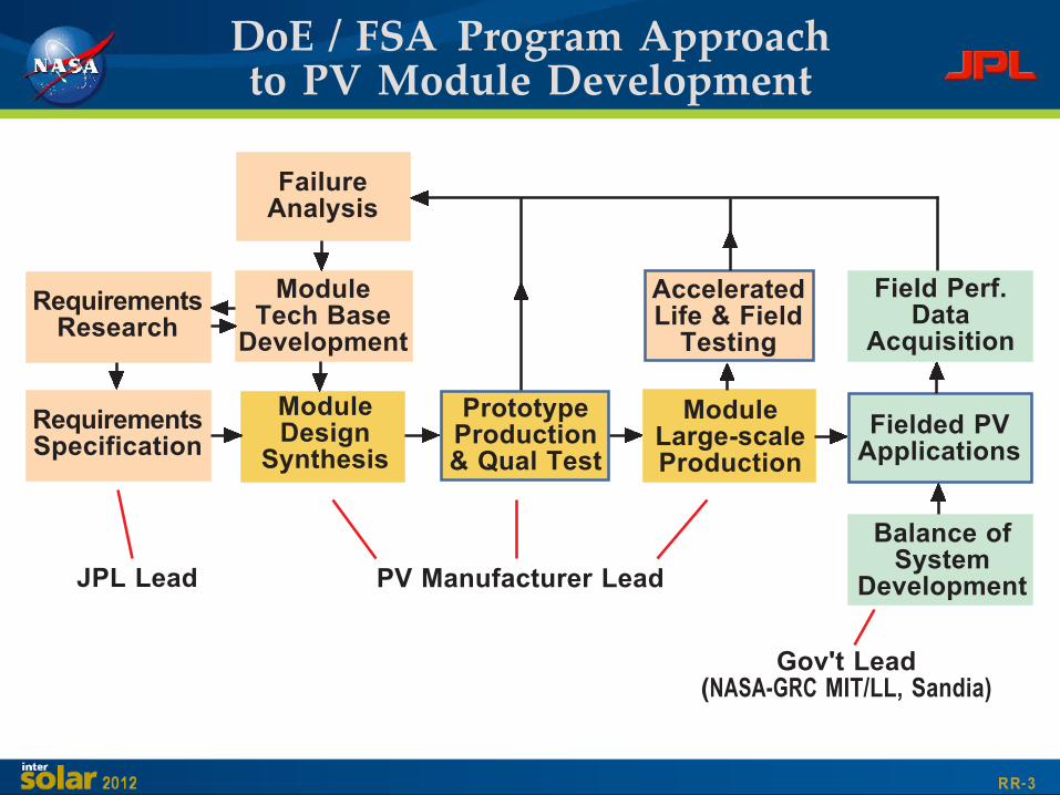
RR-3
RequirementsSpecification
PrototypeProduction& Qual Test
Fielded PVApplications
ModuleDesign
Synthesis
ModuleLarge-scaleProduction
RequirementsResearch
ModuleTech Base
Development
Balance ofSystem
DevelopmentPV Manufacturer Lead
Field Perf.Data
Acquisition
AcceleratedLife & Field
Testing
Gov't Lead(NASA-GRC MIT/LL, Sandia)
JPL Lead
FailureAnalysis
DoE / FSA Program Approachto PV Module Development

RR-4��= Performed by Nat'l Labs; �������= Performed by Module developer
� Establish detailed generic module requirements for targetapplications including system operational interfaces, environmentaland operational stress levels, reliability, and life
� Develop preliminary design able to meet requirements- Analyze and Test prototype hardware
- Resolve or design-out requirement shortfalls
� Fabricate Qual Test samples
� Conduct full set of Qualification Screening Tests
� Fabricate & Deliver Large Quantity of Production Modules
� Conduct Multi-year System-level Functional Field Tests
� Analyze performance and determine principal failure modes andfailure-mechanism parameter dependencies
- Conduct Reliability Physics Analyses- Conduct mechanism-specific Characterization and Life Tests of
sample hardware
� Feed back results into next-generation hardware and ModuleSpecification
1975-1985 PV ModuleR&D Development Process

RR-5
Qualification TestingObjectives and Attributes
OBJECTIVE
• To rapidly and economically screen module designsfor prominent (non-wearout) failure mechanisms
• To rapidly assess the relative durability ofalternative designs
ADVANTAGES
• Quick turnaround — relatively inexpensive
• Relatively standard procedures allows inter-comparison withhistorical data
• Separate tests for important environmental and operationalstresses aids identification of high-risk mechanisms
LIMITATIONS
• Minimal life-prediction capability (a relative measure ofrobustness, generally does not quantify life attributes)
• Requires multiple tests and specialized facilities to address thetotal spectrum of stressing environments
• Number of specimens insufficient to quantify random failures
RR-6
OBJECTIVE
• To accurately assess hardware functionalityand reliability with special emphasis on systemsynergisms, interactions, and interfaces
ADVANTAGES
• Complete system interfaces and operatingconditions provides reliable assessment of subsystem compatibilityissues and degradation mechanisms associated with systeminteractions or operational stresses
• Inclusion of balance-of-system (BOS) hardware provides data andconfidence in complete functional system
LIMITATIONS
• Requires complete system with all important balance-of-systemcomponents and interfaces
• Occurs very late in the design cycle; changes at this point aredifficult and expensive
• Added complexity in constructing and testing complete system
Full-Up System-Level TestingObjectives and Attributes

RR-7
Characterization and AcceleratedLife Testing Objectives and Attributes
OBJECTIVE
• To understand and quantify the fundamentalinterdependencies between performance (failurelevel), environmental and operational stress level,hardware materials and construction features, andtime
ADVANTAGES
• Mechanism-level understanding achieved by selecting specializedtests and facilities targeted at specific degradation stressenvironments and construction material parameters
• Carefully controlled parameters (generally at parametric levels) withacceleration consistent with accurate extrapolation to use conditions
LIMITATIONS
• Expensive and time consuming — requires specialized testingequipment and modestly long test durations (2 weeks to 5 years)
• Requires multiple tests to address the total spectrum of degradationmechanisms and levels
• Number of specimens insufficient to quantify random failures
Cell InterconnectFatigue Tester

RR-8
FSA Used Rapid and ThoroughCommunication of Development Results
OBJECTIVE
• Rapidly transfer research results to the entireaudience of PV researchers and developers (allIndustries, academia, and program management); i.e.have everyone rapidly build on successes achievedand quickly learn from any setbacks or deadends.
APPROACH USED
• Conducted Project Integration Meetings (PIMs) every three monthswith all parties attending and presenting — very much like technicalconference, but not open to the public. In addition, had NationalProgram meetings, and International Program meetings and plant/research facility tours. All results documented in public documents.
OBSERVATIONS
• Required openness and a high degree of collaboration — which wasachieved. Quite unique!
• Had many attributes of peer reviewed proposals
• Total FSA Project involved 131 different industrial and academiccontractors, and continued on for 10 years

RR-9
First Task: Examine Performanceof the 1975 Modules & Applications
Assessed state of terrestrial PV in 1975• Coast Guard buoys in Groton, CN• Oil platforms in the Gulf• Small remote communication apps
Lessons Learned• Modules soiled and delaminating• Wiring, Balance of System (BOS), and
maintenance were a real problem
Actions• Initiated Qual tests to screen out early
module failures• Initiated operating temperature & soiling
studies• Initiated (Block I) procurements of 1975
off-the-shelf modules for extensive testingin larger applications

RR-10
Developed Requirementsfor Future PV Markets
Central Station
Hail Probability
Residential Arrays
System Interfaces and Operational Stresses• Initiated PV system and array design contracts
(GE, Bechtel, Burt Hill Kosar Rittelmann)• Identified system voltage levels, mounting
configurations, applicable codes and missingcodes for Utility and Residential applications
Detailed Environmental Stresses• Solar and UV exposure across US• Predicted operating temperatures• Hail and Wind loading environments• Solar variability (loss-of-sun statistics)• Module electrical measurement standards
Actions• Initiated safety codes development at UL which
led to UL 1703 and National Electrical Code 690• Developed testing methods and standards for
hail, wind loading, and flammability

RR-11
Initial 1975 Block I ModulesWere Quite Immature
• Off-the-shelf 1975 designs
• Silicone rubber encapsulant
• G-10 or Alum Rear substrate
• Single cell string
• Single interconnect betweencells
• Single solder attachment tocells
• No bypass diodes

RR-12
Focused on Feedback fromFirst Large Fielded Applications
Hail Damage
Mead Nebraskatest site
Module Arcing
System Interface and Operational Stresses• High voltage arcing at broken interconnects• Hot-spot heating from broken and shadowed
cells (1 to 2% cracked cells in field)
Environment Induced Failures• High levels of soiling• Broken cells due to hail impact• Broken cells due to differential CTE• Interconnect fatigue due to differential CTE
Actions• Initiate research on alternate encapsulant
systems (PVB, EVA, glass, metal, Tedlar)
• Initiate research on arcing, soiling, hailresistance, hot-spot heating, and circuit designstrategies for improved reliability

RR-13
Focus: Develop Technology Base forEncapsulation and Module Design
Fatigue strength
Circuit designs
Cell strength
• New lamination adhesives, primers, andstabilizers (PVB, EVA, EMA) for lower cost andimproved weathering
• Circuit redundancy configurations forcontrolling impact of infrequent cell cracking andbroken interconnects
• Interconnect design methods to avoid fatigue
• Cell attachment techniques to minimizelosses due to cell cracking
• Glass strength calculation methods
• Bypass diode design and hotspot test methods
• Hail resistance data on alternative moduledesigns
• Cell fracture strength as a function ofprocessing variables

RR-14
By 1980 (Block IV), Modules hadMatured Substantially
• Glass superstrate design
• PVB & EVA encapsulant
• Rear surface films
• Aluminum frames
• Multiple cell interconnects
• Series/parallel cell strings
• Integral bypass diodes

RR-15
1980s Focus: Develop Technology Basefor 30-year Life Low-Cost Modules
Open-circuit cracked cells %/yr 0.08 0.13 0.005 EnergyShort circuit cells %/yr 0.24 0.40 0.050 EnergyInterconnect open circuits %/yr2 0.05 0.25 0.001 EnergyCell gradual power loss %/yr 0.67 1.15 0.20 EnergyModule optical degradation %/yr 0.67 1.15 0.20 EnergyFront surface soiling % 10 10 3 EnergyModule glass breakage %/yr 0.33 1.18 0.1 O&MModule open circuits %/yr 0.33 1.18 0.1 O&MModule hot-spot failures %/yr 0.33 1.18 0.1 O&MBypass diode failures %/yr 0.70 2.40 0.05 O&MModule shorts to ground %/yr2 0.022 0.122 0.01 O&MModule delamination %/yr2 0.022 0.122 0.01 O&MEncapsulant failure due years 27 20 35 Endto loss of stabilizers of life of life
Failure MechanismType of
Degradation
Units of¶Degradation
Level for¶10%Energy¶Cost
Increase*
Allocationfor
30-yearLife
Module
¶Economic¶Penalty
Life-limitingwearout
Modulefailures
PowerDegradation
Componentfailures
k=10k=0
* k=Discount rate
NormalizedPowerOutput
Years
Baseline
Target

RR-16
Evolution of Reliability Issuesduring FSA Project (1975-1985)
75 76 77 78 79 80 81 82 83 84
YearProblem Area
Photothermal Degradation
High Operating Temperature
Module Arcs and Fires
Excessive Soiling
HotSpot Heating
Voltage Breakdown
Cell Cracking
Glass Breakage
Hail Impact Damage
Structural Failure
Electrochemical Corrosion
Metallization Corrosion
Interconnect Fatigue
Bond Delamination

RR-17
HAIL IMPACTDiameter (mm) - - - 20 25.4Terminal¶Velocity¶(m/s) - - - 20.1 23.2Num. Impacts - - - 9 10
HOT-SPOT HEATING (h) - - - - 100
QUAL TEST I II III IV V NOTES
HUMIDITY CYCLINGRelative Humidity 90 85Temp. Range (°C) +70* -23 to+40 -40 to+85 *No cycling, 70°CNumber cycles - 5 10 Constant for 168 h
ELECTRICAL ISOLATION - 1500 2000* 3000* *1500 for resid.(volts) modules
WIND RESISTANCE (kPa) - - - 1.7* *Shingles only
THERMAL CYCLINGRange (°C) -40 to+90 -40 to+90Number cycles 100 50 200
MECHANICAL CYCLING* *Excluding shinglePressure (kPa) - ±2.4 modulesNumber Cycles - 100 10,000
TWISTED¶MOUNT¶(mm/m) - 20
Evolution of Qualification Testsduring FSA Project (1975-1985)

RR-18
By 1984 we'd Completed the Block VModule Development Cycle

RR-19
Evolution of Module Constructionduring Block Buys (1975-1984)
Silicone Rubber
Top Surface/Superstrate
75 76 77 78 79 80 81 82 83 84
Glass
PVB
EVA
Year
Silicone Rubber
Cell Encapsulant
Bottom Surface/Substrate
Fiberglass board
Aluminum/ S. Steel
Module Procurement Block I II III IV V
Module Technology
Laminated Films
Single Mylar/Tedlar Film

RR-20
2-in. Round Cz
Size and Shape
75 76 77 78 79 80 81 82 83 84
3-in. Round Cz
4-in. Round Cz
5-in. Round Cz
Shaped Cz
Semicrystalline
Ribbon
Ni Solder
Ti-Pd-Ag
Printed Ag
YearCell Technology
Metallization
Evolution of Crystalline Si Cellsduring Block Buys (1975-1984)
Module Procurement Block I II III IV V

RR-21
By the mid 1980s we'd CompletedSome Big Full-Scale Systems

RR-22
Late 1980s Focus: Develop TechnologyBase for Long Life and High Voltages
• Bias-Humidity — ElectrochemicalCorrosion driven by appliedvoltages and humidity
• Voltage Breakdown and Arcingthrough rear surface films and toframe
• Long-term UV-Thermal Aging

RR-23
Late 1980s Focus #1:Electrochemical Corrosion Research
Correlation to Field ConditionsFundamental Property Characterization
Accelerated Lab Testing
Relative Humidity
Su
rface C
on
du
cti
vit
y, 1
/oh
m
EVA
PVB

RR-24
Late 1980s Focus #2:Voltage Breakdown & Insulation
Fundamental Property Characterization
Module Frame Insulation Test Field Failure Biddel Partial Discharge Tester
Ap
pli
ed
Vo
lta
ge
, k
V
Applied Voltage, kVProbability of Breakdown
Pro
bab
ilit
y o
f B
reakd
ow
n
RR-25
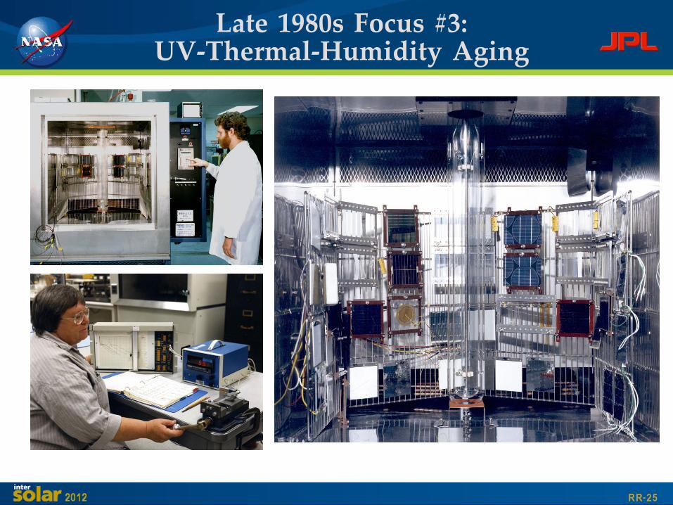
Late 1980s Focus #3:UV-Thermal-Humidity Aging

RR-26
Transmission Loss through EVAvs Temperature and UV Level
Ultraviolet Level (Suns)
No
rma
lize
d Y
ell
ow
ing
Ra
te
(Q/t
)

RR-27
Annual Hours at each Temperature-UV Level
Hourly Calculation ofEVA Yellowing Rate in Phoenix
Yellowing Rate at each Temperature-UV Level
Fromcurve-fit ofparametricUV -TempYellowingdata for
EVA
FromSOLMEThourly
weatherrecords
forPhoenix

RR-28
Conclusions fromUV-Thermal-Humidity Aging
• Predicted power loss after 30-years inPhoenix:• Ground-mounted array = 3.5%• Roof-mounted array = 7.9%*
UV-THERMAL TESTING CONCLUSIONS• UV response can be very nonlinear and difficult
to accelerate• Thermal response is much more predictable
(typically Arrhenius with approx rate doublingeach 10°C)
• Accurate regulation of temperature is critical tosuccessful UV testing
* Because roof array operates at higher temperature

RR-29
By 1990 Many More Full-Scale PVSystems had been Completed

RR-30
JPL Role in National PV ProgramSunsetted in the Early 1990's

RR-31
• Overall closed-loop module development process workedquite effectively; Critical elements included:• Qual tests for quick production screening
• Full-up systems tests for definitive operational feedback• Mechanism-level life testing for root-cause solution development
• Module Technology Base Development worked very well• Encapsulation systems development (EVA, primers, etc)• Requirements Development (natural environments, UL 1703, NEC
690)• Engineering Tech Base Development (fatigue, corrosion, glass
strength, hail resistance, hot-spot heating, voltage breakdown,etc)
• Failure analysis and measurement techniques
Summary Observationsfrom 20 years developing PV

RR-32
Summary Observations (Con't)
• Rapid open communication between all parties workedvery well• Rapid thorough feedback to all parties• Great teamwork across many organizations (Total JPL FSA
project had 131 organizations under contract)• Engineering (ES&R, Module Proc, & Encapsulation Devel)
had a total of 37 organizations under contract)• The dozens of reports and papers documenting the
Engineering technologies developed are cataloged at:http://www2.jpl.nasa.gov/adv_tech/photovol/PV_pubs.htm
• This was one of the most rewarding and fun experiencesof my life — a massive learning opportunity• Broad charter to address all obstacles• Robust budgets to support the effort• Great teamwork across many organizations