frequency tunable antenna using a magneto-dielectric material for dvb … · 2013-09-03 · huitema...
TRANSCRIPT
Downloaded from http://www.microwave.fr
Frequency Tunable Antenna Using a Magneto-Dielectric Material for DVB-H Application
Laure Huitema, Tibault Reveyrand, Jean-Luc Mattei, Eric Arnaud, Cyril Decroze, and Thierry Monediere
Published inIEEE TRANSACTIONS ON ANTENNAS AND PROPAGATION, VOL. 61, NO. 9,
September 2013, pp 4456-4466.doi:10.1109/TAP.2013.2269474
Copyright © IEEE 2013
Personal use of this material is permitted. However, permission to reprint/republish or redistribute this material for advertising or promotional purposes or for creating new collective works for resale or redistribution to servers or lists, or to reuse any copyrighted component of this work in other works must be obtained from the IEEE.
http://ieeexplore.ieee.org/xpl/articleDetails.jsp?arnumber=6542642
4456 IEEE TRANSACTIONS ON ANTENNAS AND PROPAGATION, VOL. 61, NO. 9, SEPTEMBER 2013
Frequency Tunable Antenna Using aMagneto-Dielectric Material for DVB-H
ApplicationLaure Huitema, Tibault Reveyrand, Member, IEEE, Jean-Luc Mattei, Eric Arnaud, Cyril Decroze, and
Thierry Monediere, Member, IEEE
Abstract—This paper presents an ultracompact antenna de-sign suited for digital video broadcasting–handheld (DVB-H)reception devices. The DVB-H frequency band is ranging from470 to 862 MHz and divided in 49 channels of 8 MHz. Designedto be integrated in a tablet, it is not only heavily miniaturized( at 470 MHz), but also able to covereach channel thanks to the use of a magneto-dielectric material.The advantage of using such a material is studied and describedin this paper. Moreover, the operating frequency is continuouslytuned over the whole DVB-H band by the integration of a varactordiode. This varactor diode has been characterized and modeled toproperly cosimulate its behavior within the antenna. Limitationsin terms of accepted power by the diode are emphasizing. Finally,the antenna design, including both magneto-dielectric materialand varactor diode is integrated in the DVB-H receiver device.Measurement performances are presented and discussed.
Index Terms— Digital video broadcasting–handheld (DVB-H),frequency tunable antenna, magneto-dielectric material, minia-ture antenna, pattern diversity, varactor diode.
I. INTRODUCTION
A NTENNA size reduction is restricted by fundamentalphysical limits [1]–[3], in terms of tradeoff between
radiation performances and input impedance bandwidth.Miniaturization of devices leads to the reduction of antenna’sdimensions, which becomes one of the most important chal-lenges [4] for antenna designers. This aspect is even morecritical when the targeted application is a low frequency stan-dard as the digital video broadcasting–handheld (DVB-H) forwhich the operating frequency band is ranging from 470 to 862MHz. Thus, two drawbacks are emerging:— the antenna needs to cover a very wide input impedancebandwidth of 59%;
Manuscript received November 28, 2012; revised April 15, 2013; acceptedJune 03, 2013. Date of publication June 18, 2013; date of current version Au-gust 30, 2013. This work was supported in part by the French Research AgencyProject NAOMI.L. Huitem, T. Reveyrand, E. Arnaud, C. Decroze, and T. Monediere
are with the XLIM Laboratory, OSA Department, Faculté des Scienceset Techniques, 87060 Limoges, France (e-mail: [email protected];[email protected]; [email protected]; [email protected];[email protected]).J.-L. Mattei is with LabSticc Laboratory, OSA Department, Faculté des Sci-
ences et Techniques, 87060 Limoges, France (e-mail: [email protected]).Color versions of one or more of the figures in this paper are available online
at http://ieeexplore.ieee.org.Digital Object Identifier 10.1109/TAP.2013.2269474
— the free space wavelength at 470 MHz is about 60 cm,which is very large in comparison with a DVB-H receiverdevice, e.g., a Smartphone or a tablet.
Many antennas dedicated to DVB-H reception have beeninvestigated in [5]–[10] and some are working on the wholeDVB-H band [5]–[7]. In 2012, Yonghun Cheon presenteda dual band planar inverted F antenna (PIFA), covering thewhole DVB-H band and having 70 mm 30 mm for overalldimensions, i.e., at 470 MHz [6]. A total effi-ciency of 33% is obtained in the worst case. Another article[7] presents a DVB-H antenna with best performances (totalefficiency greater than 70%) which possesses dimensions of
at 470 MHz. In spite of its electricalsmall sizes, this antenna is too big to be integrated in a DVB-Hhandheld receiver. Thus, in most cases, wireless device inte-gration remains an important issue for whole-band coveredDVB-H antennas. To overcome the DVB-H ultra-wide inputimpedance bandwidth, some antenna devices integrate activecomponents as presented by M. Berg in [8] or a matchingcircuit [9]–[11] in order to cover, at least, one user channel of8 MHz. These antennas present low instantaneous impedancebandwidths, thus small sizes and also low total efficiency,mainly induced by impedance matching circuit or active com-ponent losses. However, DVB-H specifications require lowmaximum realized gains, i.e., at 470 MHz toat 862 MHz [12].To cover a wide impedance bandwidth while maintaining
very small antennas size, the use of magneto-dielectric mate-rials has been reported in many papers [13]–[19]. Accordingto [13]–[16], magneto-dielectric substrates can permit to over-come the input impedance bandwidth limitation for small an-tennas compared to dielectric ones. Hansen and Burke [16] haveexpressed the zero-order impedance bandwidth of a patch an-tenna printed on a -thick magneto-dielectric material by thefollowing equation:
(1)
Thus, compared to high dielectric permittivity, high perme-ability materials allow to reduce the size of a patch antennawithout decreasing its relative impedance bandwidth. In [17],Niamien et al. investigates magneto-dielectric materials lossesand provides expressions of antenna impedance bandwidth andefficiency according to both dielectric and magnetic losses for
0018-926X © 2013 IEEE

HUITEMA et al.: FREQUENCY TUNABLE ANTENNA USING A MAGNETO-DIELECTRIC MATERIAL FOR DVB-H APPLICATION 4457
a patch antenna. They showed that both the radiation efficiencyand the impedance bandwidth increase with the permeability.This paper will focus on the miniaturization of a 3-D-shaped
full band DVB-H antenna with a high level of integration, fordiversity operations. This goal will be achieved through the useof both magneto-dielectric materials and active components. InSection II, the interest of using magneto-dielectric materials onthe proposed antenna will be presented through an extensive in-vestigation. Within the framework of these studies, a first pro-totype measurement will prove the advantage of using such amaterial for antenna designer’s point of view.Even if the use of magneto-dielectric materials offers great
advantages in terms of miniaturization and input impedancebandwidth enhancement, the full DVB-H bandwidth cannot beentirely covered by such a technique. For these reasons, the inte-gration of a varactor diode to tune the operating frequency of theproposed antennawill be investigated in Section III. Firstly, bothits position and its characteristics (capacitance value, qualityfactor, etc.) will be studied in order to tune the antenna all overthe DVB-H frequency band. This work will complete the lack ofinformation related tomost of varactor diode datasheets. Indeed,they only provide characteristics at low frequencies and do notgive enough parameters for antenna application point of view,such as capacitance values, serial resistance and accepted powerat RF frequencies. The chosen varactor has been characterizedaccording to antenna designer criteria and its electromagneticmodel has been deduced. This study will also exhibit powerhandling capability of the varactor diode.Finally, Section IV will present the final antenna design using
both magneto-dielectric material and the characterized varactordiode. The manufactured prototype is integrated in a DVB-Htablet and measured in an anechoic chamber. The small antennasize allows integrating two antennas in the device and thereforeapplying space diversity. In this framework, diversity perfor-mances are evaluated in a reverberation chamber.
II. MAGNETO-DIELECTRIC MATERIALS FOR ANTENNAAPPLICATIONS
The currently commercialized magneto-dielectric materials,based on fully sintered ferrite ceramics, show low ferromag-netic resonance (FMR), and high magnetic losses ( )which limit their use below 350–400 MHz. To overcome limitsof fully sintered ferrite, porous ceramic have been studied forantenna systems [20].As mentioned in Section I, the most common antenna using
magneto-dielectric materials are patch antennas. The purposeof this part is to prove that in the case of a 3-D inverted F an-tenna (IFA), using such kind of materials has same benefits thanthe ones presented by the literature [13]–[19]. This study is pre-sented in three points:— an attractive design of a 3D IFA has been firstly investi-gated;
— three antenna designs: the same antenna design has beenstudied without material, with a dielectric material andwith a magneto-dielectric material, which has the same re-fractive index;
— a prototype has been manufactured and measured to cor-roborate the simulations.
Fig. 1. 3-D Inverted F Antenna design (a). Antenna top view (b).
A. 3-D Inverted F Antenna Design
To be integrated in amobile handheld device, the antenna allo-cated volume has to be very compact. A good tradeoff betweensmall sizes and the impedance bandwidth is to choose a struc-ture based on the IFA design. Indeed, the radiating monopole ofthis kind of structure can be folded to become more compact. Inthis step of the study, the aimed frequency band is the up of theDVB-H band going till 862MHz. The antenna design, presentedin the Fig. 1, is a folded metallic ribbon. The ribbon length, andalso the gap distances illustrated on Fig. 1 (i.e., , and ) areoptimised to match the antenna around 862 MHz.The antenna design is ruled according to the following steps:— the first horizontal section of the ribbon involves a capac-itive effect, which can be compensated by a shorting line;
— the shorting line involves a parallel resonance allowing toset the input impedance without the need of a matchingcircuit;
— and lengths adjust the parallel resonance: the best wayis to have the zero of the input impedance imaginary partcorresponding to the 50 of the real one;
— the length between the metallic ribbon and the groundplane also involves a capacitive effect allowing decreasingthe resonant frequency.
However, it should be noted that the resonance frequency isparamount governed by the ribbon global length, which couldbe compared to a quarter wavelength monopole.This structure presents quietly small dimensions and its shape
is interesting with the aim of miniaturizing by loading it withdifferent kinds of materials.As far as it will be integrated in a tablet, the antenna is studied
on a 230 mm 130 mm ground plane and incorporated in itscorner. The radiating element is fed by a 50 coplanar wave-guide printed on a FR4 substrate ( ).
B. Three Antenna Designs
In this subsection, the previous folded monopole is loaded bytwo materials: a high permittivity material ( ) anda magneto-dielectric material ( , )as depicted on Fig. 2.The dielectric permittivity is selected in order to
ensure a similar miniaturization factor as , ,corresponding to a same refractive index. Thus, except for thevolume, which is reduced by a ratio of 1.5, the antenna de-sign is the same as the reference one (without substrate). The
4458 IEEE TRANSACTIONS ON ANTENNAS AND PROPAGATION, VOL. 61, NO. 9, SEPTEMBER 2013
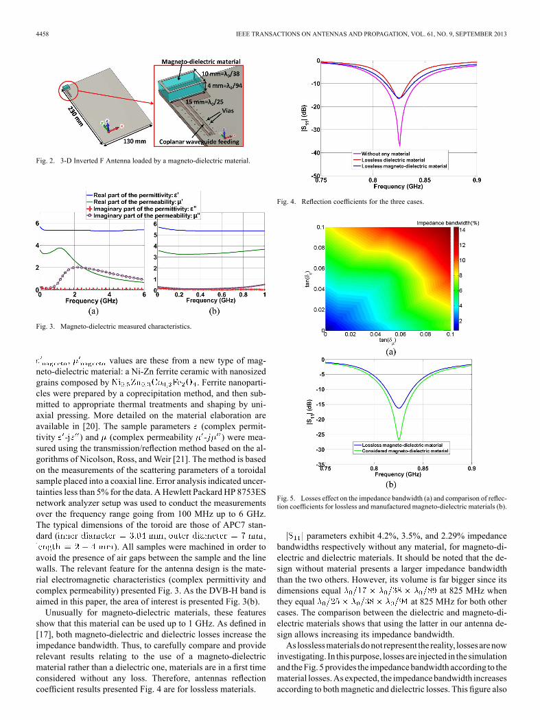
Fig. 2. 3-D Inverted F Antenna loaded by a magneto-dielectric material.
Fig. 3. Magneto-dielectric measured characteristics.
, values are these from a new type of mag-neto-dielectric material: a Ni-Zn ferrite ceramic with nanosizedgrains composed by . Ferrite nanoparti-cles were prepared by a coprecipitation method, and then sub-mitted to appropriate thermal treatments and shaping by uni-axial pressing. More detailed on the material elaboration areavailable in [20]. The sample parameters (complex permit-tivity - ) and (complex permeability - ) were mea-sured using the transmission/reflection method based on the al-gorithms of Nicolson, Ross, andWeir [21]. The method is basedon the measurements of the scattering parameters of a toroidalsample placed into a coaxial line. Error analysis indicated uncer-tainties less than 5% for the data. AHewlett Packard HP 8753ESnetwork analyzer setup was used to conduct the measurementsover the frequency range going from 100 MHz up to 6 GHz.The typical dimensions of the toroid are those of APC7 stan-dard ( , ,
). All samples were machined in order toavoid the presence of air gaps between the sample and the linewalls. The relevant feature for the antenna design is the mate-rial electromagnetic characteristics (complex permittivity andcomplex permeability) presented Fig. 3. As the DVB-H band isaimed in this paper, the area of interest is presented Fig. 3(b).Unusually for magneto-dielectric materials, these features
show that this material can be used up to 1 GHz. As defined in[17], both magneto-dielectric and dielectric losses increase theimpedance bandwidth. Thus, to carefully compare and providerelevant results relating to the use of a magneto-dielectricmaterial rather than a dielectric one, materials are in a first timeconsidered without any loss. Therefore, antennas reflectioncoefficient results presented Fig. 4 are for lossless materials.
Fig. 4. Reflection coefficients for the three cases.
Fig. 5. Losses effect on the impedance bandwidth (a) and comparison of reflec-tion coefficients for lossless and manufactured magneto-dielectric materials (b).
parameters exhibit 4.2%, 3.5%, and 2.29% impedancebandwidths respectively without any material, for magneto-di-electric and dielectric materials. It should be noted that the de-sign without material presents a larger impedance bandwidththan the two others. However, its volume is far bigger since itsdimensions equal at 825 MHz whenthey equal at 825 MHz for both othercases. The comparison between the dielectric and magneto-di-electric materials shows that using the latter in our antenna de-sign allows increasing its impedance bandwidth.As losslessmaterialsdonot represent the reality, lossesarenow
investigating. In thispurpose, lossesare injected in the simulationand theFig. 5provides the impedancebandwidth according to thematerial losses.As expected, the impedance bandwidth increasesaccording to bothmagnetic and dielectric losses. This figure also
HUITEMA et al.: FREQUENCY TUNABLE ANTENNA USING A MAGNETO-DIELECTRIC MATERIAL FOR DVB-H APPLICATION 4459
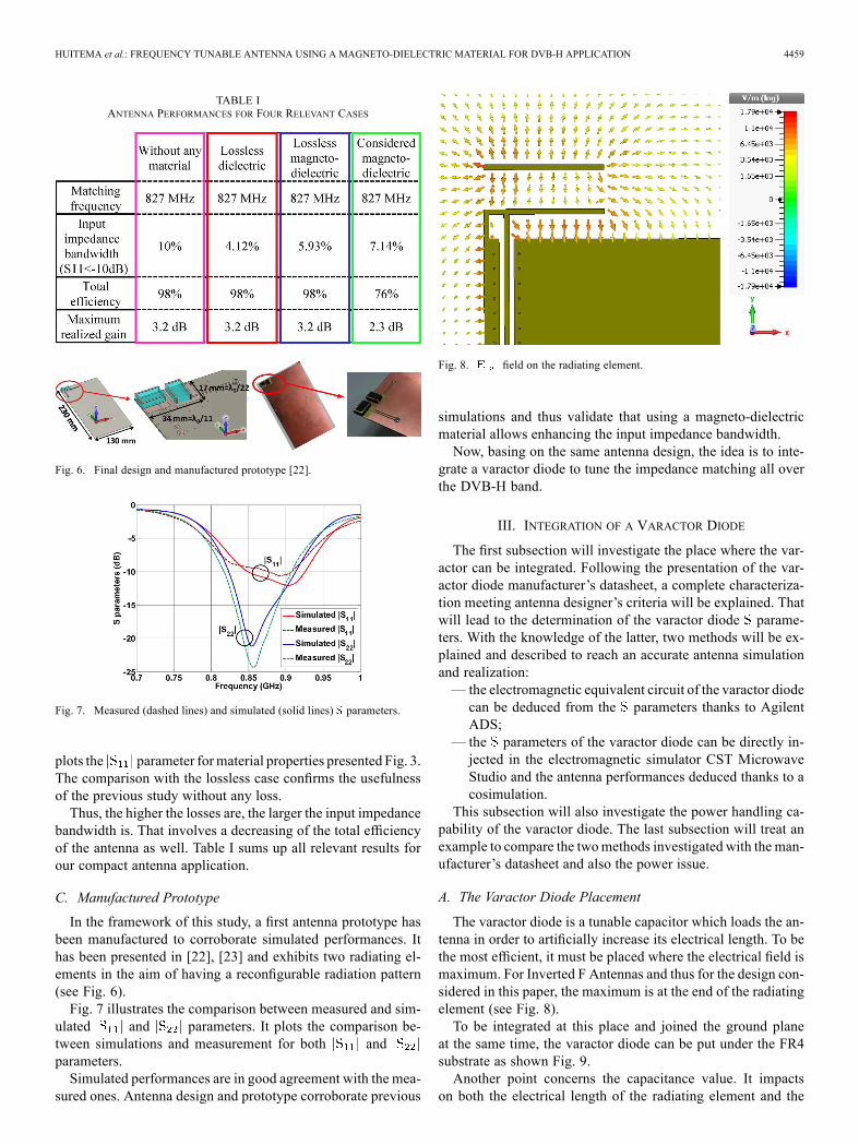
TABLE IANTENNA PERFORMANCES FOR FOUR RELEVANT CASES
Fig. 6. Final design and manufactured prototype [22].
Fig. 7. Measured (dashed lines) and simulated (solid lines) parameters.
plots the parameter formaterial properties presented Fig. 3.The comparison with the lossless case confirms the usefulnessof the previous study without any loss.Thus, the higher the losses are, the larger the input impedance
bandwidth is. That involves a decreasing of the total efficiencyof the antenna as well. Table I sums up all relevant results forour compact antenna application.
C. Manufactured Prototype
In the framework of this study, a first antenna prototype hasbeen manufactured to corroborate simulated performances. Ithas been presented in [22], [23] and exhibits two radiating el-ements in the aim of having a reconfigurable radiation pattern(see Fig. 6).Fig. 7 illustrates the comparison between measured and sim-
ulated and parameters. It plots the comparison be-tween simulations and measurement for both andparameters.Simulated performances are in good agreement with the mea-
sured ones. Antenna design and prototype corroborate previous
Fig. 8. field on the radiating element.
simulations and thus validate that using a magneto-dielectricmaterial allows enhancing the input impedance bandwidth.Now, basing on the same antenna design, the idea is to inte-
grate a varactor diode to tune the impedance matching all overthe DVB-H band.
III. INTEGRATION OF A VARACTOR DIODE
The first subsection will investigate the place where the var-actor can be integrated. Following the presentation of the var-actor diode manufacturer’s datasheet, a complete characteriza-tion meeting antenna designer’s criteria will be explained. Thatwill lead to the determination of the varactor diode parame-ters. With the knowledge of the latter, two methods will be ex-plained and described to reach an accurate antenna simulationand realization:— the electromagnetic equivalent circuit of the varactor diodecan be deduced from the parameters thanks to AgilentADS;
— the parameters of the varactor diode can be directly in-jected in the electromagnetic simulator CST MicrowaveStudio and the antenna performances deduced thanks to acosimulation.
This subsection will also investigate the power handling ca-pability of the varactor diode. The last subsection will treat anexample to compare the twomethods investigated with the man-ufacturer’s datasheet and also the power issue.
A. The Varactor Diode Placement
The varactor diode is a tunable capacitor which loads the an-tenna in order to artificially increase its electrical length. To bethe most efficient, it must be placed where the electrical field ismaximum. For Inverted F Antennas and thus for the design con-sidered in this paper, the maximum is at the end of the radiatingelement (see Fig. 8).To be integrated at this place and joined the ground plane
at the same time, the varactor diode can be put under the FR4substrate as shown Fig. 9.Another point concerns the capacitance value. It impacts
on both the electrical length of the radiating element and the
4460 IEEE TRANSACTIONS ON ANTENNAS AND PROPAGATION, VOL. 61, NO. 9, SEPTEMBER 2013
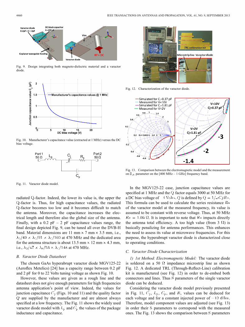
Fig. 9. Design integrating both magneto-dielectric material and a varactordiode.
Fig. 10. Manufacturer’s capacitance value (extracted at 1 MHz) versus the DCbias voltage.
Fig. 11. Varactor diode model.
radiated -factor. Indeed, the lower its value is, the upper the-factor is. Thus, for high capacitance values, the radiated-factor becomes too low and it becomes difficult to match
the antenna. Moreover, the capacitance increases the elec-trical length and therefore also the global size of the antenna.Finally, with a 0.2 pF – 2 pF capacitance values range, thefinal design depicted Fig. 9, can be tuned all over the DVB-Hband. Material dimensions are 11 mm 7 mm 3.5 mm, i.e.,
at 470 MHz and the dedicated areafor the antenna structure is about 13.5 mm 12 mm 4.3 mm,i.e., at 470 MHz.
B. Varactor Diode Datasheet
The chosen GaAs hyperabrupt varactor diode MGV125-22(Aeroflex Metelics) [24] has a capacity range between 0.2 pFand 2 pF for 0 to 22 Volts tuning voltage as shown Fig. 10.However, these values are given as a rough line and the
datasheet does not give enough parameters for high frequenciesantenna application’s point of view. Indeed, the values forjunction capacitance (Figs. 10 and 11) and the quality factorare supplied by the manufacturer and are almost always
specified at a low frequency. The Fig. 11 shows the widely usedvaractor diode model with and the values of the packageinductance and capacitance.
Fig. 12. Characterization of the varactor diode.
Fig. 13. Comparison between the electromagnetic model and the measurementon parameter on the [400 MHz – 1 GHz] frequency band.
In the MGV125-22 case, junction capacitance values arespecified at 1 MHz and the factor equals 3000 at 50 MHz fora DC bias voltage of . is defined by .This formula can be used to calculate the series resistanceof the varactor model at the measured frequency, its value isassumed to be constant with reverse voltage. Thus, at 50 MHz
. It is important to note that impacts directlythe antenna total efficiency. A too high value (from 3 ) isbasically penalizing for antenna performances. This enhancesthe need to assess its value at microwave frequencies. For thispurpose, the hyperabrupt varactor diode is characterized closeto operating conditions.
C. Varactor Diode Characterization
1) 1st Method: Electromagnetic Model: The varactor diodeis soldered on a 50 impedance microstrip line as shownFig. 12. A dedicated TRL (Through-Reflect-Line) calibrationkit is manufactured (see Fig. 12) in order to de-embed bothconnectors and lines. Thus parameters of the single varactordiode can be deduced.Considering the varactor diode model previously presented
in Fig. 11, , , , and values can be deduced foreach voltage and for a constant injected power of .Therefore, model component values are adjusted (see Fig. 13)in order their parameters to correspond with the measuredones. The Fig. 13 shows the comparison between parameters

HUITEMA et al.: FREQUENCY TUNABLE ANTENNA USING A MAGNETO-DIELECTRIC MATERIAL FOR DVB-H APPLICATION 4461
Fig. 14. Electromagnetic model.
Fig. 15. Capacitance values versus the DC bias voltage.
Fig. 16. Co-simulation of the antenna including measured parameters of thediode.
of the determined electromagnetic model (Agilent ADS) andthe measured ones (see Fig. 12) for 2 Volts and 10 Volts DCbias voltages.These results are given as an example and the same work
has been done for varactor reverse bias voltages varying from2 V to 22 V with a 2 V step. As expected, the correspondingelectromagneticmodel presents constant values according to theDC bias voltage (Fig. 14): , , and
.The value presented in Fig. 15 decreases as a function of
DC bias voltage value.2) 2nd Method: CoSimulation: Another way is to directly
insert the parameters touchstone file of the varactor diode inthe antenna electromagnetic simulation as illustrated in Fig. 16.Thanks to the previous TRL calibration, only the varactor
diode parameters are inserted in the simulator. By this way,both antenna and varactor diode are combined and the param-eters of the global device can be directly simulated. An example(presented paragraph Section III-D) will confirm that the twoprevious methods exhibit similar antenna performances.3) Power Characterization: Fig. 17 provides some informa-
tion regarding the accepted power by the varactor diode: highinjected power involves some varactor diode distortions.This figure presents parameters of the diode for only three
values of injected power: , 0 dBm and 10 dBm. Thenonlinear distortion of the diode has been studied. It reveals
Fig. 17. Measured parameters according to the injected power.
Fig. 18. Basic IFA prototype [25].
that the varactor diode model well fits measurements for aninjected RF power lower than . Beyond this injectedpower (see for 0 dBm), no varactor model can fit the measure-ment. Regarding antenna’s parameters, the following examplewill show that a large RF power (upper than ) involvesa mismatched antenna. As far as the DVB-H application, thesystem is only working in receiving mode, the diode distortionwill never appear and the linear electromagnetic model can beused and integrated in the electromagnetic simulator. Indeed, forreceiver devices, the antenna accepted power is far lower than
.
D. Example of a Basic Antenna
This subsection investigates an example to show the interestof the previous varactor diode characterization. This was brieflypresented in [25], it is completed here by adding the first method(electromagnetic model) and the power characterization. Abasic IFA prototype loaded by the same varactor diode (seeFig. 18) has been manufactured.It has been measured for a RF power and its
performances compared with three simulations: with bothpresented methods and with the varactor diode’s datasheet(Fig. 19). parameters show that both investigated methodsand measurement present a good agreement. Moreover, they aredifferent from parameters determined with the varactordiode datasheet. That underlines the relevance of the varactordiode characterization. Regarding the antenna total efficiency,it equals 50% in the real case whereas it reaches 60% when thevaractor datasheet is used in electromagnetic simulations.Power characterization is illustrated on Fig. 20. This figure
reminds the measured parameter for a power of .For a 10 dBm injected power, the measured parameter iscompared with the simulated one with the second method.

4462 IEEE TRANSACTIONS ON ANTENNAS AND PROPAGATION, VOL. 61, NO. 9, SEPTEMBER 2013
Fig. 19. parameters for different cases.
Fig. 20. parameters according to the injected power.
Fig. 21. DC bias Tee with SMD components and its integration upstream fromthe antenna.
There is a good agreement between the measurement and thesimulation. This figure shows that the nonlinearity of the var-actor diode disturbs the parameter of the antenna. Thus,this kind of varactor diode has to be used only for receptiondevices.Therefore, this section has presented how to integrate and
characterize a varactor diode. It reveals the importance of thediode characterization in a design flow dedicated to antennastructure.
Fig. 22. Integration of two antennas in the tablet dedicated to the DVB-H re-ception.
Fig. 23. Measured input impedances versus frequency for several DC bias volt-ages.
Fig. 24. Measured reflection coefficients for several DC bias voltages.
IV. ANTENNA PERFORMANCES
A. Measured and Simulated Performances of the Antenna
A prototype of the tunable antenna has been realized (seeFig. 21) and measured. For the diode polarization, a DC biasTee is optimized with SMD components and measured on theDVB-H band (see Fig. 21). After being validated, it is integratedupstream from the antenna structure as shown Fig. 21.In order to improve the quality and the reliability of wireless
links, the final mobile device is integrating two antennas (seeFig. 22) for diversity operations.Figs. 23 and 24 present, respectively, the variation of the
input impedances and parameters of the antenna versusfrequency for different values of the varactor diode bias volt-ages.There is a good agreement between simulation and measure-
ment. Indeed, the antenna working band is continuously tuned
HUITEMA et al.: FREQUENCY TUNABLE ANTENNA USING A MAGNETO-DIELECTRIC MATERIAL FOR DVB-H APPLICATION 4463
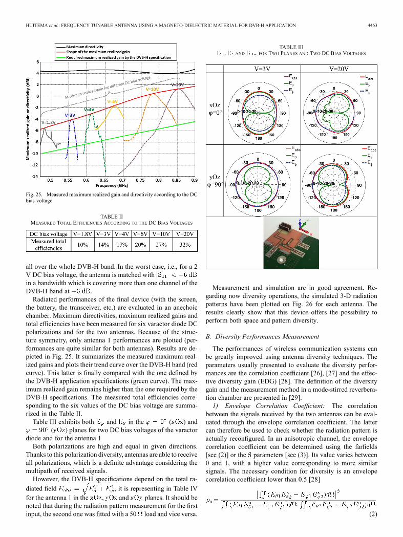
Fig. 25. Measured maximum realized gain and directivity according to the DCbias voltage.
TABLE IIMEASURED TOTAL EFFICIENCIES ACCORDING TO THE DC BIAS VOLTAGES
all over the whole DVB-H band. In the worst case, i.e., for a 2V DC bias voltage, the antenna is matched within a bandwidth which is covering more than one channel of theDVB-H band at .Radiated performances of the final device (with the screen,
the battery, the transceiver, etc.) are evaluated in an anechoicchamber. Maximum directivities, maximum realized gains andtotal efficiencies have been measured for six varactor diode DCpolarizations and for the two antennas. Because of the struc-ture symmetry, only antenna 1 performances are plotted (per-formances are quite similar for both antennas). Results are de-picted in Fig. 25. It summarizes the measured maximum real-ized gains and plots their trend curve over the DVB-H band (redcurve). This latter is finally compared with the one defined bythe DVB-H application specifications (green curve). The max-imum realized gain remains higher than the one required by theDVB-H specifications. The measured total efficiencies corre-sponding to the six values of the DC bias voltage are summa-rized in the Table II.Table III exhibits both and in the ( ) and
( ) planes for two DC bias voltages of the varactordiode and for the antenna 1Both polarizations are high and equal in given directions.
Thanks to this polarization diversity, antennas are able to receiveall polarizations, which is a definite advantage considering themultipath of received signals.However, the DVB-H specifications depend on the total ra-
diated field , it is representing in Table IVfor the antenna 1 in the , and planes. It should benoted that during the radiation pattern measurement for the firstinput, the second one was fitted with a 50 load and vice versa.
TABLE III, AND FOR TWO PLANES AND TWO DC BIAS VOLTAGES
Measurement and simulation are in good agreement. Re-garding now diversity operations, the simulated 3-D radiationpatterns have been plotted on Fig. 26 for each antenna. Theresults clearly show that this device offers the possibility toperform both space and pattern diversity.
B. Diversity Performances Measurement
The performances of wireless communication systems canbe greatly improved using antenna diversity techniques. Theparameters usually presented to evaluate the diversity perfor-mances are the correlation coefficient [26], [27] and the effec-tive diversity gain (EDG) [28]. The definition of the diversitygain and the measurement method in a mode-stirred reverbera-tion chamber are presented in [29].1) Envelope Correlation Coefficient: The correlation
between the signals received by the two antennas can be eval-uated through the envelope correlation coefficient. The lattercan therefore be used to check whether the radiation pattern isactually reconfigured. In an anisotropic channel, the envelopecorrelation coefficient can be determined using the farfields[see (2)] or the parameters [see (3)]. Its value varies between0 and 1, with a higher value corresponding to more similarsignals. The necessary condition for diversity is an envelopecorrelation coefficient lower than 0.5 [28]
(2)

4464 IEEE TRANSACTIONS ON ANTENNAS AND PROPAGATION, VOL. 61, NO. 9, SEPTEMBER 2013
TABLE IVMEASURED (BLUE LINE) AND SIMULATED (RED LINE) RADIATION PATTERNS
FOR TWO DC BIAS VOLTAGES
Fig. 26. Directivity patterns when the antenna 2 (a) or the antenna 1 (b) isexcited.
(3)
Fig. 27 shows the envelope correlation coefficient calculatedwith the (3) for a 10 V polarization of the varactor diode. It re-mains lower than 0.5 (equals to ), that allows to concludethat the radiation patterns is reconfigured on the working bandat 10 V. The same phenomenon can be observed for other valuesof DC bias voltage.2) Effective Diversity Gain: The effective diversity gain
is evaluated in a mode-stirred reverberation chamber. Theschematic of the measurement process is shown in Fig. 28.A reverberation chamber is a metallic cavity which supportsa large number of resonant cavity modes. The statistically
Fig. 27. Envelope correlation coefficient for a 10 V-DC bias voltage.
Fig. 28. Measurement process in the mode stirred reverberation chamber.
Fig. 29. Effective diversity gain for a 10 V-DC bias voltage.
uniform field distribution can be obtained by mechanicallysteering these modes inside the chamber [30]–[32].As shown in Fig. 28, a fixed horn antenna excites the chamber
where the antenna under test is positioned on a rotating arm. Toobtain a statistically uniform channel, the stirrer and the antennaunder test are rotated around the axis.The cumulative probability density (CDF) is calculated from
the signal-to-noise ratio (SNR) measurements. An example ofthe CDF curve computed at 780MHz is plotted in Fig. 29. In ab-scissa, the threshold SNR is normalized by the SNR of the refer-ence antenna. A half-wavelength dipole antenna, also measuredin the reverberation chamber, has been used to provide this ref-erence. This one has been used in order to evaluate the effectivediversity gain. It was matched at the measured frequency whereit presented a total efficiency near 100%.

HUITEMA et al.: FREQUENCY TUNABLE ANTENNA USING A MAGNETO-DIELECTRIC MATERIAL FOR DVB-H APPLICATION 4465
It is obvious that the diversity techniques enhance the recep-tion quality, while the effective diversity gain at a 1% prob-ability is higher than 0 dB. At 780 MHz, i.e., for a varactordiode polarization equals to 10 V, it is equal to 5 dB for Max-imum Ratio Combining (MRC). Because antennas efficienciesare lower at the beginning of the DVB-H band, the effective di-versity gain at a 1% is lower and equals 3.5 dB at 470 MHz.
V. CONCLUSION
The paper started by underlining the interest of using a mag-neto-dielectric material in the case of a 3D Inverted F Antennaapplication. To ensure the relevance and usefulness of this in-vestigation, the use of such a material has been compared withthe equivalent dielectric case for lossless materials. Indeed,losses enhance the input impedance bandwidth and to carefullycompare and show the relevance of using a magneto-dielectricmaterial rather than a dielectric one, the best way is to considerlossless materials. Thus, while disregarding losses, results ex-hibit that using a magneto-dielectric material allows enhancingthe impedance bandwidth. Of course, considering the real case,i.e., manufactured magneto-dielectric material with losses,the impedance bandwidth is all the more enhanced. To finishabout the magneto-dielectric material study, simulations in anantenna application have been corroborated by the realizationand the measurement of a prototype.To cover the ultra-wide DVB-H band, the second axe of the
paper proposed the integration of a varactor diode. Integratesuch an active component for antenna application requires someattention. First of all, its position and the capacitance range havebeen determined to continuously cover the DVB-H band. A var-actor diode corresponding to the requirements has been foundbut its characteristics (given by its datasheet) were not accurateenough for RF frequency bands and do not give enough infor-mation for antenna application point of view. The novelty inthis paper is the characterization of the varactor diode. Its elec-tromagnetic model has been determined and integrated in thesimulator. This characterization has highlighted that this linearmodel is only available for low injected powers, till .In our case, i.e., for reception devices, the injected power to thediode is far lower than . It is thus important to noticethat the proposed antenna design is not available for devicesworking in transmission.Finally, the final design, which takes into account both the
magneto-dielectric material and the characterized varactordiode, has been integrated in the tablet dedicated to the DVB-Hreception. Material dimensions are 11 mm 7 mm 3.5 mm,i.e., at 470 MHz and the dedicatedarea for the antenna structure is about 13.5 mm 12 mm 4.3mm, i.e., at 470 MHz.The device was measured both in anechoic and reverbera-
tion chambers. The anechoic chambermeasurements show goodperformances. The realized gain remains higher than the one re-quired by the DVB-H application and the total efficiency higherthan 10%, 32% is obtained for the highest DVB-H frequencyband. The reverberation measurement shows a 5 dB effective di-versity gain at 780 MHz for maximum ratio combining (MRC).The space diversity has allowed enhancing the quality and reli-ability of the wireless link.
REFERENCES[1] R. C. Hansen, “Fundamental limitations in antennas,” Proc. IEEE, vol.
69, no. 2, pp. 170–182, Feb. 1981.[2] J. S. McLean, “A re-examination of the fundamental limits on the radi-
ation of electrically small antennas,” IEEE Trans. Antennas Propag.,vol. 44, no. 5, p. 672, May 1996.
[3] R. Collin and S. Rothschild, “Evaluation of antenna ,” IEEE Trans.Antennas Propag., vol. AP-12, no. 1, pp. 23–27, Jan. 1964.
[4] A. K. Skrivervik, J.-F. Zurcher, O. Staub, and J. R. Mosig, “PCSantenna design: The challenge of miniaturization,” IEEE AntennasPropag. Mag., vol. 43, no. 4, pp. 12–27, Aug. 2001.
[5] R. Caso, A. D’Alessandro, A. A. Serra, P. Nepa, and G. Manara, “Acompact dual-band PIFA for DVB-T and WLAN applications,” IEEETrans. Antennas Propag., vol. 60, no. 4, pp. 2084–2087, Apr. 2012.
[6] Y. Cheon, J. Lee, and J. Lee, “Quad-band monopole antenna includingLTE 700MHzwithmagneto-dielectric material,” IEEEAntennasWire-less Propag. Lett., vol. 11, pp. 137–140, 2012.
[7] L. Huitema, M. Koubeissi, C. Decroze, and T. Monediere, “Ultrawide-band dielectric resonator antenna for DVB-H and GSM applications,”IEEE Antennas Wireless Propag. Lett., vol. 8, pp. 1021–1027, 2009.
[8] M. Berg, M. Komulainen, V. Palukuru, H. Jantunen, and E. Sa-lonen, “Frequency-tunable DVB-H antenna for mobile terminals,” inProc. IEEE Int. Symp. Antennas Propag. Soc., Jun. 9–15, 2007, pp.1072–1075.
[9] L. Huang and P. Russer, “Electrically tunable antenna design procedurefor mobile applications,” IEEE Trans. Microw. Theory Tech., vol. 56,no. 12, pp. 2789–2797, Dec. 2008.
[10] D.-H. Choi, Y.-T. Im, Y.-J. Cho, and S.-O. Park, “A tunable antennafor DVB-H applications,” IEEE Antennas Wireless Propag. Lett., vol.6, pp. 515–517, 2007.
[11] Y. Li, Z. Zhang, W. Chen, Z. Feng, and M. F. Iskander, “A compactDVB-H antenna with varactor-tuned matching circuit,” Microw. Opt.Technol. Lett., vol. 52, pp. 1786–1789, 2010.
[12] Digital Video Broadcasting (DVB), DVB-H Implementation Guide-lines, ETSI TR 102 377 v1.2.1, Nov. 2005, ETSI TR 102 377 v1.2.1.
[13] H. Mosallaei and K. Sarabandi, “Magneto-dielectrics in electromag-netics: Concept and applications,” IEEE Trans. Antennas Propag., vol.52, no. 6, pp. 1558–1567, Jun. 2004.
[14] P. M. T. Ikonen, K. N. Rozanov, A. V. Osipov, P. Alitalo, and S. A.Tretyakov, “Magnetodielectric substrates in antenna miniaturization:Potential and limitations,” IEEE Trans. Antennas Propag., vol. 54, no.11, pp. 3391–3399, Nov. 2006.
[15] P. M. T. Ikonen, K. N. Rozanov, A. V. Osipov, P. Alitalo, and S. A.Tretyakov, “Magnetodielectric substrates in antenna miniaturization:Potential and limitations,” IEEE Trans. Antennas Propag., vol. 54, no.11, pp. 3391–3399, Nov. 2006.
[16] R. C. Hansen and M. Burke, “Antennas with magneto-dielectrics,”Mi-crow. Opt. Technol. Lett., vol. 26, pp. 75–78, Jul. 2000.
[17] C. Niamien, S. Collardey, A. Sharaiha, and K. Mahdjoubi, “Compactexpressions for efficiency and bandwidth of patch antennas over lossymagneto-dielectric materials,” IEEE Antennas Wireless Propag. Lett.,vol. 10, pp. 63–66, 2011.
[18] F. Ferrero, A. Chevalier, J. M. Ribero, R. Staraj, J. L. Mattei, and Y.Queffelec, “A new magneto-dielectric material loaded, tunable UHFantenna for handheld devices,” IEEE Antennas Wireless Propag. Lett.,vol. 10, pp. 951–954, 2011.
[19] J. F. Pintos, A. Louzir, P. Minard, J. Perraudeau, J. L. Mattei, D.Souriou, and P. Queffelec, “Ultra-miniature UHF antenna using mag-neto-dielectric material,” in Proc. 14th Int. Symp. Antenna Technol.Appl. Electromagn. Amer. Electromagn. Conf. (ANTEM-AMEREM),Jul. 5–8, 2010, pp. 1–4.
[20] J.-L. Mattei, L. Huitema, P. Queffelec, J.-F. Pintos, P. Minard, A.Sharahia, B. Jamnier, F. Ferrero, R. Staraj, D. Souriou, and A. Thakur,“Suitability of Ni-Zn ferrites ceramics with controlled porosity asgranular substrates for mobile handset miniaturized antennas,” IEEETrans. Magn., vol. 47, no. 10, pp. 3720–3723, Oct. 2011.
[21] Weir and B. William, “Automatic measurement of complex dielectricconstant and permeability at microwave frequencies,” Proc. IEEE, vol.62, no. 1, p. 33,36, Jan. 1974.
[22] L. Huitema, M. Koubeissi, C. Decroze, and T. Monediere, “Overviewof two ultra compact antennas using original materials with pattern di-versity,” in Proc. Int. Workshop Antenna Technol. (iWAT), Mar. 7–9,2011, pp. 50–53.
[23] L. Huitema, M. Hajj, T. Monédière, D. Souriou, A. Chevalier, J.-L.Mattei, and P. Queffelec, “Overview of reconfigurable and compact an-tennas using a magneto-dielectric material,” in Progress Electromagn.Res. Symp., Marrakesh, Morocco, Mar. 20–23, 2011.
[24] Aeroflex Metelics Datasheet, [Online]. Available: http://www.aeroflex.com/AMS/Metelics/pdfiles/MGV_Series_Hyperabrupt_A17041.pdf

4466 IEEE TRANSACTIONS ON ANTENNAS AND PROPAGATION, VOL. 61, NO. 9, SEPTEMBER 2013
[25] L. Huitema, T. Reveyrand, E. Arnaud, C. Decroze, and T. Monediere,“A compact and reconfigurable DVB-H antenna for mobile handhelddevices,” in Proc. 5th Eur. Conf. Antennas Propag. (EUCAP), , Apr.11–15, 2011, pp. 1314–1317.
[26] G. A. Mavridis, J. N. Sahalos, and M. T. Chryssomalis, “Spatial diver-sity two branch for wireless devices,” IEEE Lett., vol. 42, pp. 266–268,2006.
[27] M. B. Knudsen and G. F. Pedersen, “Spherical outdoor to indoorpower spectrum model at the mobile terminal,” IEEE J. Select. AreasCommun., vol. 20, no. 6, pp. 1156–1169, Aug. 2002.
[28] S. Blanch, J. Romeu, and I. Corbella, “Exact representation of antennasystem diversity performance from input parameter description,” Elec-tron. Lett., vol. 39, no. 9, pp. 705–707, May 2003.
[29] P. S. Kildal, K. Rosengren, J. Byun, and J. Lee, “Definition of effectivediversity gain and howmeasure it in a reverberation chamber,”Microw.Opt. Technol. Lett., vol. 34, pp. 56–59, 2002.
[30] R. G. Vaughan and J. B. Andersen, “Antenna diversity in mobile com-munications,” IEEE Trans. Veh. Technol., vol. 36, no. 4, pp. 149–172,Nov. 1987.
[31] T. Bolin, A. Derneryd, G. Kristensson, V. Plicanic, and Z. Ying, “Two-antenna receive diversity performance in indoor environment,” Elec-tron. Lett., vol. 41, no. 22, pp. 1205–1206, Oct. 2005.
[32] M. Mouhamadou, C. A. Tounou, C. Decroze, D. Carsenat, andMonediere, “Active measurements of antenna diversity performancesusing a specific test-bed, in several environments,” Int. J. RF Microw.Comput.-Aided Eng., pp. 264–271, May 2010.
Laure Huitema was born in Limoges, France, in1984. She received the M.S. and Ph.D. degrees intelecommunications high frequencies and opticsfrom Limoges University, Limoges, France, in 2008and 2011, respectively.From 2011 to 2012, she was a Postdoctoral
Research Fellow at the Atomic Energy Commission(CEA), Laboratory of Electronics and Informa-tion Technology (LETI), Grenoble, France. Sheis currently an Associate Professor in the OSA(Wireless communications and Effect of EM Wave)
Department of XLIM Research Institute. Her research interests include activeantennas, Dielectric Resonator Antennas and also multiband antennas.Dr. Huitema is the recipient of the best student paper award at the 2010 IEEE
International Workshop on Antenna Technology (iWAT 2010) and of the beststudent paper award at the 2010 Journées de Charactérisation Microondes etMatériaux (JCMM 2010).
Tibault Reveyrand (M’07) received the Ph.D.degree from the University of Limoges, Limoges,France, in 2002.From 2002 to 2004, he was a Postdoctoral Sci-
entist with CNES (French Space Agency). From2005 to 2013, he was a CNRS Engineer at XLIM. In2013, he joined University of Colorado at Boulder,Boulder, CO, USA, as a Research Associate. Hisresearch interests include the characterization andmodeling of RF and microwave nonlinear compo-nents and devices.
Dr. Reveyrand was the recipient of the 2002 European GaAs Best PaperAward and is amember of the IEEEMTT-11 “MicrowaveMeasurements” Tech-nical Committee.
Jean-Luc Mattei received was born in France, in1961. He received the Ph.D. degree in solid statephysics from University Joseph Fourier, Grenoble,France, in 1990.He is currently an Assistant Professor in the
Electronic Department of the University of Brest,and Member of the Lab-STICC (UMR CNRS 6285).His main research activities include the ferriteprocessing (powder preparation and sintering),the study of heterogeneous granulars materials forapplications in the microwave range, and mainly
about the demagnetizing effects. He is also interested in the modeling ofelectromagnetic fields in composite media.
Eric Arnaud was born in France, in 1970. Hereceived the Diplôme D’Etudes Supérieures Spe-cialisées (DESS) and Ph.D degrees in electronic andtelecommunication from the University of Limoges,Limoges, France, in 1994 and 2010, respectively. Hedid his Ph.D. on circularly polarized EBG antenna.From 1996 to 2001, he has been Microwave
responsible of Free-Electron Laser (L.U.R.E labo-ratory). Since 2001, he has been in charge of XLIMlaboratory antenna test range and he participated toseveral research projects related to design, devel-
opment and characterization of antennas. His research interests include thefields of circularly polarized EBG antenna and realization of antennas throughink-jetting of conductive inks on RF substrates
Cyril Decroze received the Ph.D. degree in telecom-munications engineering from the University ofLimoges, Limoges, France, in 2002.He is currently an Associate Professor with the
Wave and Associated Systems (OSA) Department,XLIM Research Institute, University of Limoges.Since 2006, he has been in charge of the wirelesssystems activity in the XLIM-OSA Department.His research interests include antennas design,propagation channel, MIMO systems, and digitalwireless communications.
Thierry Monediere was born in 1964, in Tulle,France. He received the Ph.D. degree from theIRCOM Laboratory, University of Limoges,Limoges, France, in 1990.He is currently a Professor at the University of
Limoges and develops his research activities in XlimLaboratory (UMR CNRS/University of Limoges).He research interests include multifunctions an-tennas, EBG antennas, and active antennas.