frame scaffolding - superior scaffold services | the ... · pdf filesuperior scaffold services...
TRANSCRIPT
1-800-247-9206 www.superiorscaffold.com
FRAME SCAFFOLDING
Ove
r 50 Years of Experience
Designing and Implemen
ting505050
yearsThe Leader in Scaffold Services
Sup
eri
or
Sca
ffold
Serv
ices
1
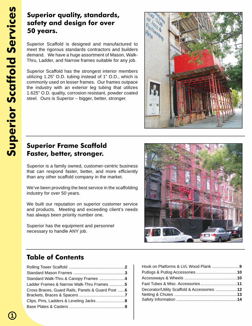
Superior Scaffold is designed and manufactured to meet the rigorous standards contractors and builders demand. We have a huge assortment of Mason, Walk-Thru, Ladder, and Narrow frames suitable for any job.
Superior Scaffold has the strongest interior members utilizing 1.25” O.D. tubing instead of 1” O.D., which is commonly used on lesser frames. Our frames outpace the industry with an exterior leg tubing that utilizes 1.625” O.D. quality, corrosion resistant, powder coated steel. Ours is Superior – bigger, better, stronger.
Superior is a family owned, customer-centric business that can respond faster, better, and more effi ciently than any other scaffold company in the market.
We’ve been providing the best service in the scaffolding industry for over 50 years.
We built our reputation on superior customer service and products. Meeting and exceeding client’s needs has always been priority number one.
Superior has the equipment and personnel necessary to handle ANY job.
Rolling Tower Scaffold .................................................2Standard Mason Frames .............................................3Standard Walk-Thru & Canopy Frames ......................4 Ladder Frames & Narrow Walk-Thru Frames .............5Cross Braces, Guard Rails, Panels & Guard Post ......6Brackets, Braces & Spacers ........................................7Clips, Pins, Ladders & Leveling Jacks .........................8Base Plates & Casters .................................................8
Hook on Platforms & LVL Wood Plank ........................9Putlogs & Putlog Accessories ....................................10 Accessways & Wheels ..............................................10Fast Tubes & Misc. Accessories ................................11Decorator/Utility Scaffold & Accessories ...................12Netting & Chutes .......................................................13Safety Information .....................................................14
Superior quality, standards, safety and design for over 50 years.
Superior Frame ScaffoldFaster, better, stronger.
Table of Contents
Rollin
g To
wer Sca
ffold
2
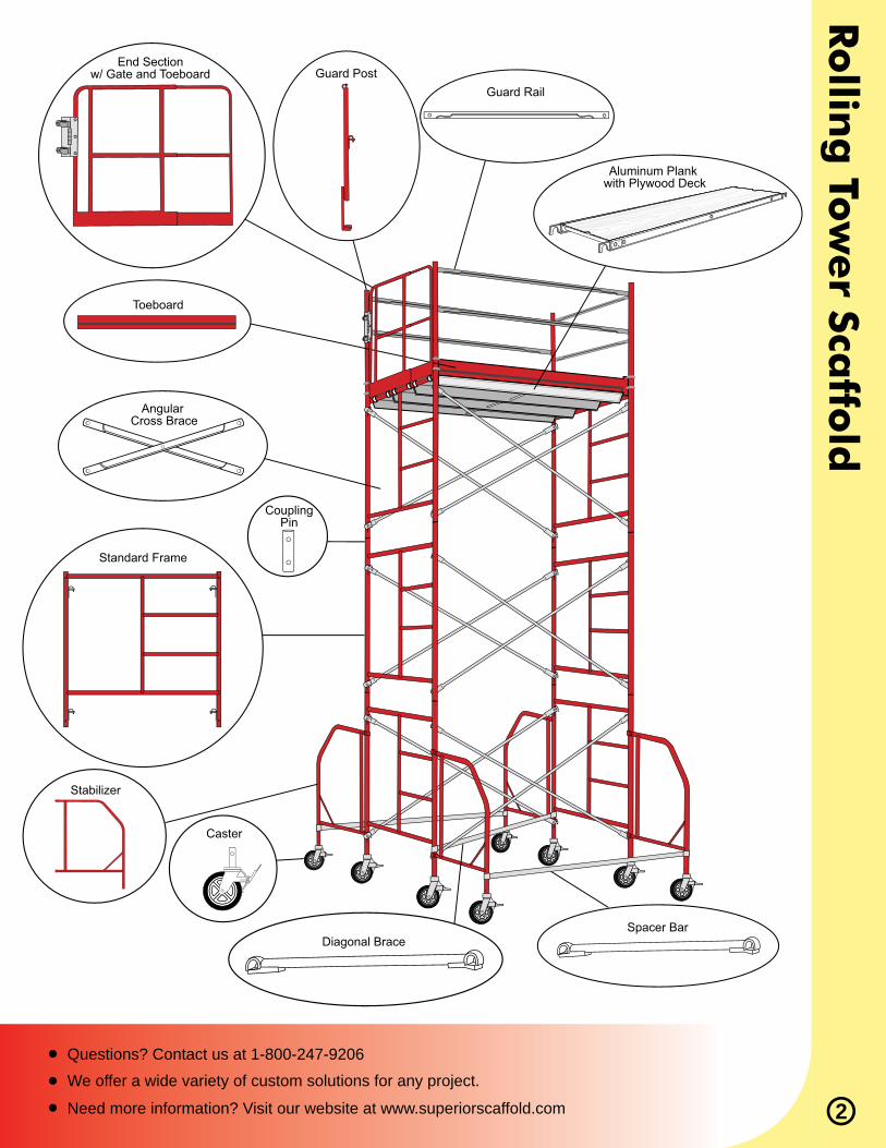
Aluminum Plank with Plywood Deck
Guard RailGuard Post
End Sectionw/ Gate and Toeboard
Toeboard
Angular Cross Brace
Standard Frame
Stabilizer
Caster
Spacer Bar
CouplingPin
Diagonal Brace
Questions? Contact us at 1-800-247-9206We offer a wide variety of custom solutions for any project.
Need more information? Visit our website at www.superiorscaffold.com
Part No. Description Lock Spacing Weight
Sta
nd
ard
Ma
son
Fra
mes
15200
1’1”
2’1”
3’1”
6’7”
5’1”
5’
5’
5’
5’
5’1”
1”
7”
7”
7”
7”
1”
1”
1”
15500
15602
1530015100
1510015200153001550015602
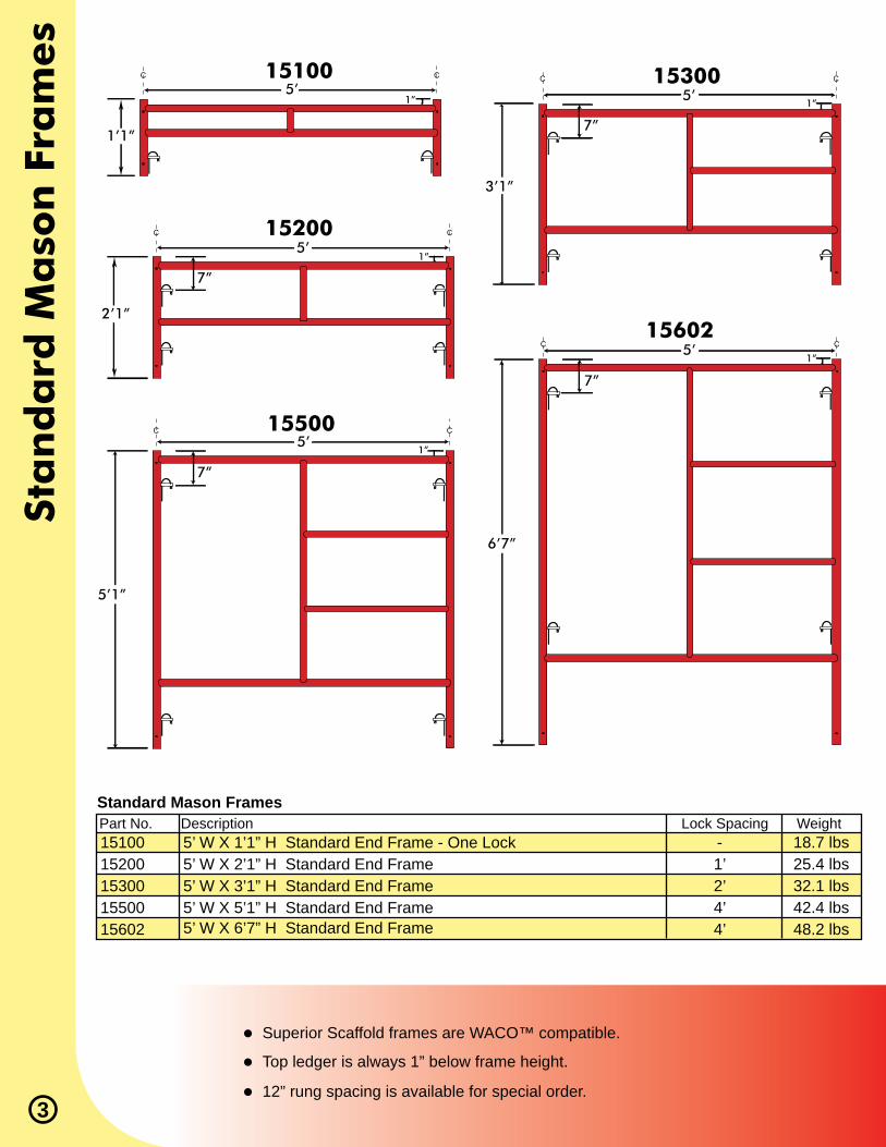
18.7 lbs25.4 lbs32.1 lbs42.4 lbs48.2 lbs
-1’2’4’4’
5’ W X 1’1” H Standard End Frame - One Lock5’ W X 2’1” H Standard End Frame 5’ W X 3’1” H Standard End Frame 5’ W X 5’1” H Standard End Frame 5’ W X 6’7” H Standard End Frame
Standard Mason Frames
3
Top ledger is always 1” below frame height.
Superior Scaffold frames are WACO™ compatible.
12” rung spacing is available for special order.
Part No. Description Lock Spacing Weight
Part No. Description Lock Spacing Weight
Stan
da
rd W
alk
-Thru
& C
an
op
y Fram
es
6’7”
6’7”
7’6”
6’7”
2’
2’
20”
5’
5’
7’4”
5’15606 15607
767
15628
767
156061560715628
105.8 lbs
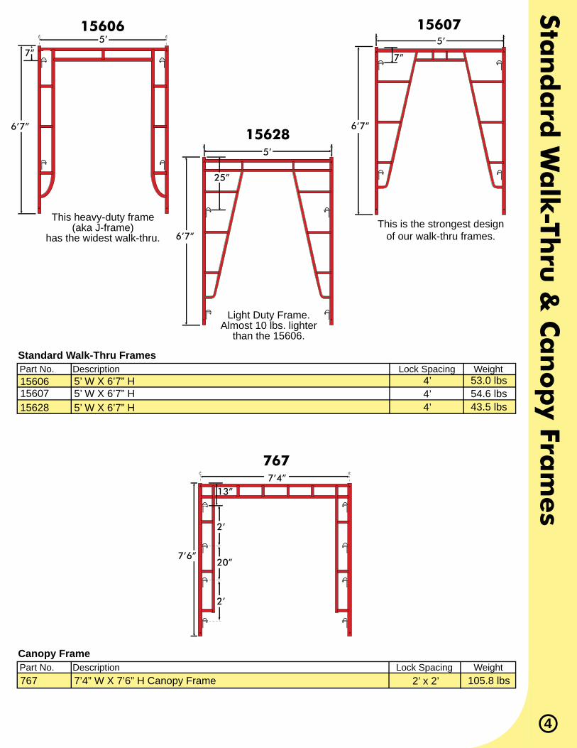
53.0 lbs54.6 lbs43.5 lbs
2’ x 2’
4’4’4’
7’4” W X 7’6” H Canopy Frame
5’ W X 6’7” H5’ W X 6’7” H5’ W X 6’7” H
Canopy Frame
Standard Walk-Thru Frames
This heavy-duty frame (aka J-frame)
has the widest walk-thru.
Light Duty Frame. Almost 10 lbs. lighter
than the 15606.
This is the strongest design of our walk-thru frames.
4
7” 7”
13”
25”

Lad
der
Fra
mes
& N
arr
ow
Wa
lk-T
hru
Fra
mes
5
Part No. Description Lock Spacing Weight
Part No. Description Lock Spacing Weight
123001250012600
13300134021350213602
21.0 lbs29.2 lbs36.8 lbs
21.4 lbs30.0 lbs32.1 lbs40.6 lbs
2’4’4’
2’3’4’4’
29” W X 3’1” H Ladder Frame29” W X 5’1” H Ladder Frame29” W X 6’7” H Ladder Frame
3’ W X 3’1” H Narrow Frame3’ W X 4’1” H Narrow Frame3’ W X 5’1” H Narrow Frame3’ W X 6’7” H Narrow Frame
Ladder Frames
Narrow Frames
12300
1350213602
1250012600
Part No. Description Lock Spacing Weight1350013600
34.9 lbs40.1 lbs
4’4’
3’ W X 5’1” H Narrow Walk-Thru Frame 3’ W X 6’7” H Narrow Walk-Thru Frame
Narrow Walk-Thru Frames
1350013600
3’1”5’1” 6’7”
29”29”
29”
5’1” 6’7”
3’3’
5’1” 6’7”
3’3’
7”7”
7”7”
7”
7”7”

Cro
ss Bra
ces, G
ua
rd R
ails, P
an
els &
Gu
ard
Post
6
Part No. Lock Spacing Span Weight “X”
Part No. Lock Spacing Span Weight “X”
25205252062520725305253062530725308
244042440524406244072440824410
61 1/4”73”
84 7/8”64 5/8”75 7/8”87 3/8”
99”
67 3/4”76 7/8”86 1/2”96 3/4”
107 3/8”129 1/4”
10.00 lbs11.60 lbs13.50 lbs10.20 lbs12.00 lbs15.90 lbs17.11 lbs
13.23 lbs14.33 lbs15.43 lbs17.20 lbs18.74 lbs22.05 lbs
5’ 6’7’5’6’7’8’
4’5’6’7’8’
10’
1’1’1’2’2’2’2’
3’ & 4’3’ & 4’3’ & 4’3’ & 4’3’ & 4’3’ & 4’
Single Hole Angular Cross Brace
Double Hole Angular Cross Brace
Part No. Description Weight320 9.3 lbsStandard Guard Post
320
Guard Post
Part No. Description Weight32504326663277732888GRGADJGRGTB
19.8 lbs13.0 lbs15.2 lbs16.9 lbs30.5 lbs38.0 lbs
5’ Hanging Guard Rail EndrailGuard Rail Panel 6’ LongGuard Rail Panel 7’ LongGuard Rail Panel 8’ LongGuard Rail Gate Adj.Guard Rail Gate (Adj. w/Toeboard)
Guard Rail Panels32504 32777
GRGTB
Part No. Description Weight323033250532606327073280832710
3.1 lbs4.9 lbs5.8 lbs6.3 lbs6.6 lbs
10.5 lbs
Guard Rail 3’ LongGuard Rail 5’ LongGuard Rail 6’ LongGuard Rail 7’ LongGuard Rail 8’ LongGuard Rail 10’ Long
Guard Rails
32606
32707
32505
OSHA Regulation 1910.28 (f)(15) “Guardrails...and toeboards, shall be installed at all open sides on all scaffolds more than 10 feet above the ground or fl oor.”
84”
72”
60”
Span
“X”
Lock Spacing
Bra
ckets
, B
race
s &
Sp
ace
rs
7
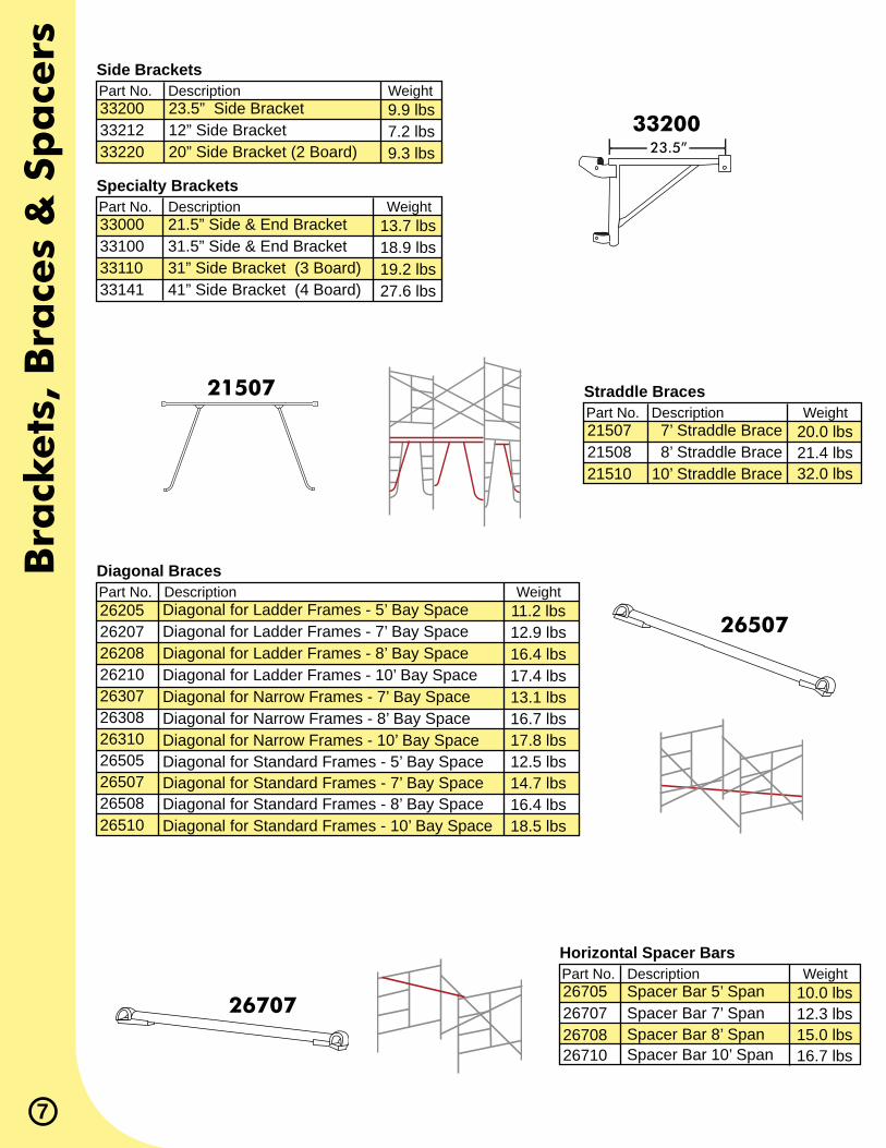
Part No. Description Weight215072150821510
20.0 lbs21.4 lbs32.0 lbs
7’ Straddle Brace 8’ Straddle Brace10’ Straddle Brace
Straddle Braces
Part No. Description Weight
Part No. Description Weight
Part No. Description Weight
332003321233220
33000331003311033141
2620526207262082621026307263082631026505265072650826510
9.9 lbs7.2 lbs9.3 lbs
13.7 lbs18.9 lbs19.2 lbs27.6 lbs
11.2 lbs12.9 lbs16.4 lbs17.4 lbs13.1 lbs16.7 lbs17.8 lbs12.5 lbs14.7 lbs16.4 lbs18.5 lbs
23.5” Side Bracket12” Side Bracket 20” Side Bracket (2 Board)
21.5” Side & End Bracket31.5” Side & End Bracket31” Side Bracket (3 Board)41” Side Bracket (4 Board)
Diagonal for Ladder Frames - 5’ Bay SpaceDiagonal for Ladder Frames - 7’ Bay SpaceDiagonal for Ladder Frames - 8’ Bay SpaceDiagonal for Ladder Frames - 10’ Bay SpaceDiagonal for Narrow Frames - 7’ Bay SpaceDiagonal for Narrow Frames - 8’ Bay SpaceDiagonal for Narrow Frames - 10’ Bay SpaceDiagonal for Standard Frames - 5’ Bay SpaceDiagonal for Standard Frames - 7’ Bay SpaceDiagonal for Standard Frames - 8’ Bay SpaceDiagonal for Standard Frames - 10’ Bay Space
Side Brackets
Specialty Brackets
Diagonal Braces
33200
21507
26507
Part No. Description Weight26705267072670826710
10.0 lbs12.3 lbs15.0 lbs16.7 lbs
Spacer Bar 5’ Span Spacer Bar 7’ Span Spacer Bar 8’ Span Spacer Bar 10’ Span
Horizontal Spacer Bars
26707
23.5”
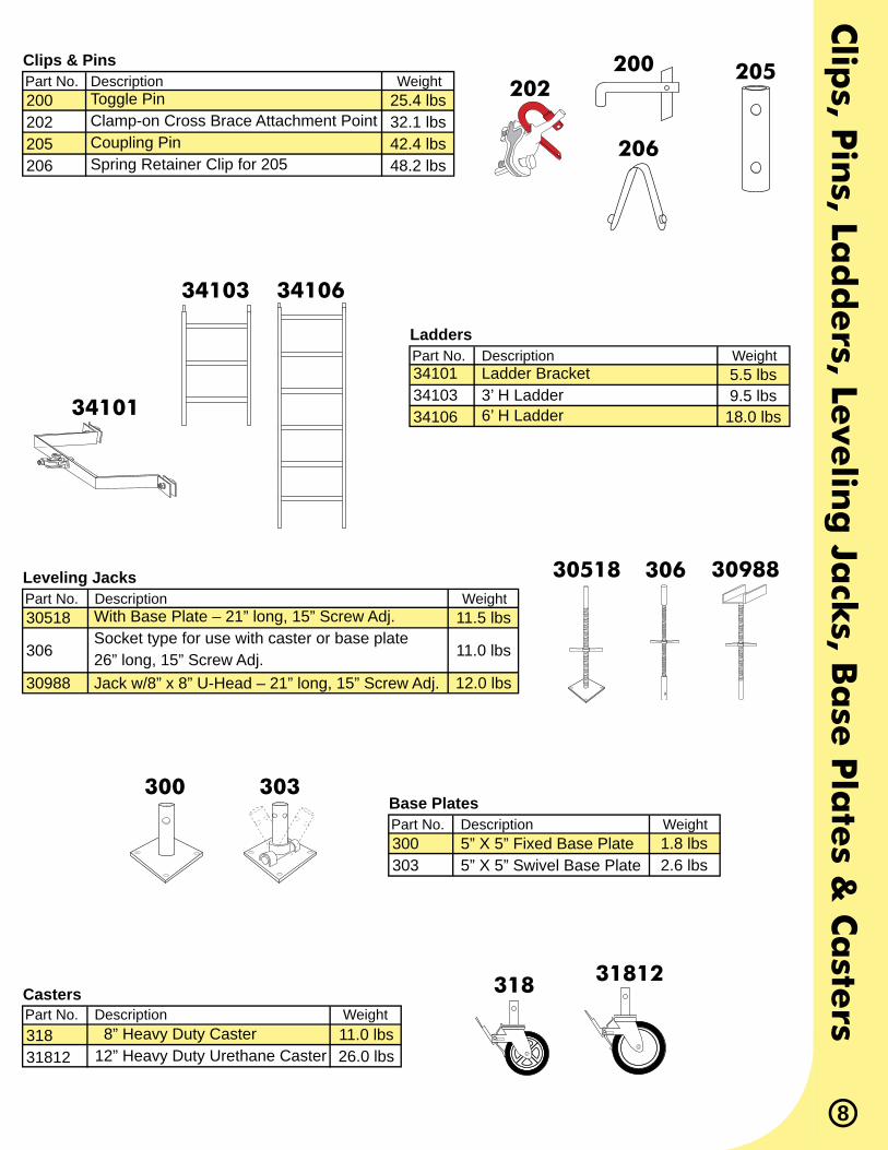
Part No. Description Weight200202205206
25.4 lbs32.1 lbs42.4 lbs48.2 lbs
Toggle PinClamp-on Cross Brace Attachment PointCoupling PinSpring Retainer Clip for 205
Clips & Pins 200202
205
206
Part No. Description Weight31831812
11.0 lbs26.0 lbs
8” Heavy Duty Caster12” Heavy Duty Urethane Caster
Casters 318 31812
Part No. Description Weight30518
306
30988
11.5 lbs
11.0 lbs
12.0 lbs
With Base Plate – 21” long, 15” Screw Adj.Socket type for use with caster or base plate26” long, 15” Screw Adj.Jack w/8” x 8” U-Head – 21” long, 15” Screw Adj.
Leveling Jacks 30518 306 30988
Clip
s, Pin
s, Lad
ders, Le
velin
g Ja
cks, B
ase
Pla
tes &
Ca
sters
8
Part No. Description Weight300303
1.8 lbs2.6 lbs
5” X 5” Fixed Base Plate5” X 5” Swivel Base Plate
Base Plates300 303
Part No. Description Weight341013410334106
5.5 lbs9.5 lbs
18.0 lbs
Ladder Bracket3’ H Ladder6’ H Ladder
Ladders
34103 34106
34101

Hook
on
Pla
tform
s &
LV
L W
ood
Pla
nk
9
Part No. Description Weight
Part No. Description Weight
Load Condition Span*
Superior only uses laminated scaffold plank (or LVL – Laminated Veneer Lumber) for strength and durability. Each length of plank is 9.5” wide X 1.5” thick.
Laminated Veneer Lumber (LVL) is a super strong yet lightweight scaffold plank.
Features include: • Individually proof tested • Tough and long lasting • Lightweight and versatile • 100% renewable wood resources
OSHA, Scaffold Specifi cations – 1926 Subpart L, Appendix A.* - 9.50” Width x Standard 1.5” Nominal Thickness
Part No. Description Weight
530719530819531019530724530824531024
ML04ML06ML08ML10ML16WB02
50 psf75 psf1-Person2-Person3-Person
550719550819551019
27.0 lbs30.0 lbs39.0 lbs32.0 lbs43.0 lbs53.0 lbs
16.8 lbs25.2 lbs33.6 lbs42.0 lbs67.2 lbs 4.2 lbs
25.0 lbs34.0 lbs40.0 lbs
7’ L X 19” W Aluminum Platform w/Plywood Deck 8’ L X 19” W Aluminum Platform w/Plywood Deck 10’ L X 19” W Aluminum Platform w/Plywood Deck 7’ L X 24” W Aluminum Platform w/Plywood Deck 8’ L X 24” W Aluminum Platform w/Plywood Deck10’ L X 24” W Aluminum Platform w/Plywood Deck
4’ Long Laminated Plank 6’ Long Laminated Plank 8’ Long Laminated Plank10’ Long Laminated Plank16’ Long Laminated PlankWood Block
10’ 6”9’ 0”
10’ 6”8’ 6”6’ 0”
7’ L x 19” W All Aluminum Platform 8’ L x 19” W All Aluminum Platform10’ L x 19” W All Aluminum Platform
Hook on Platform - Aluminum w/ Plywood Deck
LVL Wood Plank (OSHA Grade Laminated Scaffold Plank)
Simple Span Loading Condition
Hook on Platform - All Aluminum
530719
550719
ML08
Spans are from center to center of scaffold supports.
The “Person” load is defi ned in ANSI A10.8 as a 200-pound person with 50 pounds of equipment.
Pu
tlog
s, Pu
tlog
Acce
ssorie
s, Acce
sswa
ys & W
heels
10
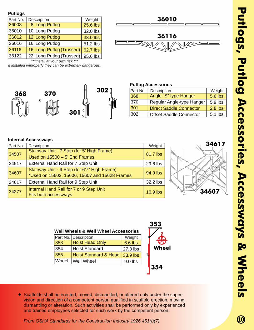
Scaffolds shall be erected, moved, dismantled, or altered only under the super-vision and direction of a competent person qualifi ed in scaffold erection, moving, dismantling or alteration. Such activities shall be performed only by experienced and trained employees selected for such work by the competent person.
From OSHA Standards for the Construction Industry 1926.451(f)(7)
Part No. Description Weight360083601036012360163611636122
25.6 lbs32.0 lbs38.0 lbs51.2 lbs62.7 lbs95.6 lbs
8’ Long Putlog10’ Long Putlog12’ Long Putlog16’ Long Putlog16’ Long Putlog (Trussed)22’ Long Putlog (Trussed)
Putlogs
Part No. Description Weight368370301302
5.6 lbs5.9 lbs2.8 lbs5.1 lbs
Angle “S” type HangerRegular Angle-type HangerDirect Saddle ConnectorOffset Saddle Connector
Putlog Accessories
***Install at your own risk.*** If installed improperly they can be extremely dangerous.
36010
36116
368 370
301
302
Part No. Description Weight
34507
34517
34607
34617
34277
81.7 lbs
29.6 lbs
94.9 lbs
32.2 lbs
16.9 lbs
Stairway Unit - 7 Step (for 5’ High Frame)Used on 15500 – 5’ End FramesExternal Hand Rail for 7 Step UnitStairway Unit - 9 Step (for 6’7” High Frame)*Used on 15602, 15606, 15607 and 15628 FramesExternal Hand Rail for 9 Step UnitInternal Hand Rail for 7 or 9 Step UnitFits both accessways
Internal Accessways 34617
34607
Part No. Description Weight353354355Wheel
6.6 lbs27.3 lbs33.9 lbs9.0 lbs
Hoist Head OnlyHoist StandardHoist Standard & HeadWell Wheel
Well Wheels & Well Wheel Accessories353
Wheel
354

Fast
Tu
bes
& M
isc.
Acc
ess
ori
es
11
Part No. Description WeightFT4FT6FT8FT10FT12FT13FT16FT20
13.3 lbs 18.1 lbs 23.2 lbs 27.9 lbs 32.3 lbs 35.1 lbs 42.4 lbs 55.7 lbs
4’ Fast Tube with End Fittings 6’ Fast Tube with End Fittings 8’ Fast Tube with End Fittings10’ Fast Tube with End Fittings12’ Fast Tube with End Fittings13’ Fast Tube with End Fittings16’ Fast Tube with End Fittings20’ Fast Tube with End Fittings
Fast Tube (1.9” O.D.)
Part No. Description Weight4210242202FTBP
4.1 lbs3.6 lbs 6.5 lbs
Dual Swivel Clamp - 1.625” to 1.90” O.D.Dual Rigid Clamp - 1.625” to 1.90” O.D.Fixed Base Plate with Stem for Fast Tubes
Fast Tube Accessories
FT8
42102 42202
FTBP
47100 92100Part No. Description Weight391019210047100520
24” Wide Base Stabilizer48” Wide Base StabilizerNailing PlateExtension Leg
Misc. Accessories
Questions? Contact us at 1-800-247-9206
We offer a wide variety of custom solutions for any project. Contact us to discuss your particular needs.
Need more information? Visit our website at www.superiorscaffold.com
14.0 lbs31.5 lbs1.1 lbs
16.0 lbs
48”
Fits both frames and tubes- from 1.625 to 1.90 O.D.
Deco
rato
r/Utility Sca
ffold
& A
ccesso
ries
12
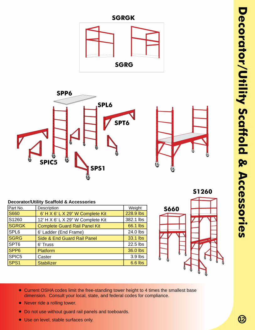
Part No. Description WeightS660S1260SGRGKSPL6SGRGSPT6SPP6SPIC5SPS1
6’ H X 6’ L X 29” W Complete Kit12’ H X 6’ L X 29” W Complete KitComplete Guard Rail Panel Kit6’ Ladder (End Frame)Side & End Guard Rail Panel6’ TrussPlatformCasterStabilizer
Decorator/Utility Scaffold & Accessories
Current OSHA codes limit the free-standing tower height to 4 times the smallest basedimension. Consult your local, state, and federal codes for compliance.
Do not use without guard rail panels and toeboards.
Use on level, stable surfaces only.
Never ride a rolling tower.
SGRGK
SGRG
SPP6
SPT6
SPL6
SPS1SPIC5
S660
S1260
228.9 lbs382.1 lbs
66.1 lbs24.0 lbs33.1 lbs22.5 lbs36.0 lbs
3.9 lbs6.6 lbs
Nett
ing
& C
hu
tes
13
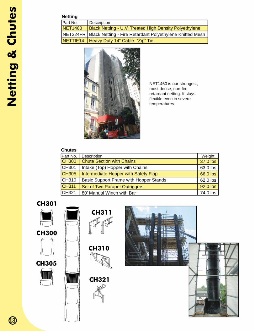
Part No. Description WeightCH300CH301CH305CH310CH311CH321
Chute Section with ChainsIntake (Top) Hopper with ChainsIntermediate Hopper with Safety FlapBasic Support Frame with Hopper StandsSet of Two Parapet Outriggers80’ Manual Winch with Bar
Chutes
37.0 lbs63.0 lbs66.0 lbs62.0 lbs92.0 lbs74.0 lbs
CH301
CH300
CH305
CH321
CH310
CH311
Part No. DescriptionNET1460NET324FRNETTIE14
Black Netting - U.V. Treated High Density PolyethyleneBlack Netting - Fire Retardant Polyethylene Knitted MeshHeavy Duty 14” Cable “Zip” Tie
Netting
NET1460 is our strongest, most dense, non-fi re retardant netting. It stays fl exible even in severe temperatures.
Safe
ty Info
rma
tion
14
For Frame Scaffolds, System Scaffolds, Tube and Clamp Scaffolds and Rolling ScaffoldsDEVELOPED FOR INDUSTRY BY SCAFFOLD INDUSTRY ASSOCIATION, INC. (SIA) and THE SCAFFOLD, SHORING & FORMING INSTITUTE (SSFI) It shall be the responsibility of all users to read and comply with the following common sense guidelines which are designed to promote safety in the erecting, dismantling and use of Scaffolds. These guidelines do not purport to be all-inclusive nor to supplant or replace other additional safety and precautionary measures to cover usual or unusual conditions. If these guidelines in any way conflict with any state, local, provincial, federal or other government statute or regulation, said statute or regulation shall supersede these guidelines and it shall be the responsibility of each user to comply therewith.
I. GENERAL GUIDELINESPost these scaffolding safety guidelines in a conspicuous place and be sure • that all persons who erect, dismantle or use scaffolding are aware of them, and also use them in tool box safety meetings.Follow all state, local and federal codes, ordinances and regulations pertaining • to scaffolding.Survey the job site. A survey shall be made of the job site by a competent • person for hazards, such as untamped earth fills, ditches, debris, high tension wires, unguarded openings, and other hazardous conditions created by other trades. These conditions should be corrected or avoided as noted in the following sections.Inspect all equipment before using. Never use any equipment that is damaged • or defective in any way. Mark it or tag it as defective. Remove it from the job site.Scaffolds must be erected in accordance with design and/or manufacturers’ • recommendations.Do not erect, dismantle or alter a scaffold unless under the supervision of a • competent person.Do not abuse or misuse the scaffold equipment.• Erected scaffolds should be continually inspected by users to be sure that • they are maintained in safe condition. Report any unsafe condition to your supervisor.Never take chances! If in doubt regarding the safety or use of the scaffold, • consult your scaffold supplier.Never use equipment for purposes or in ways for which it was not intended.• Do not work on scaffolds if your physical condition is such that you feel dizzy or • unsteady in any way.Do not work under the influence of alcohol or illegal drugs.•
II. GUIDELINES FOR ERECTION AND USE OF SCAFFOLDSScaffold base must be set on an adequate sill or pad to prevent slipping or • sinking and fixed thereto where required. Any part of a building or structure used to support the scaffold shall be capable • of supporting the maximum intended load to be applied.Use adjusting screws or other approved methods instead of blocking to adjust • to uneven grade conditions. Bracing, leveling & plumbing of frame scaffolds -•
Plumb and level all scaffolds as the erection proceeds. Do not force frames 1. or braces to fit. Level the scaffold until proper fit can easily be made.Each frame or panel shall be braced by horizontal bracing, cross bracing, 2. diagonal bracing or any combination thereof for securing vertical members together laterally. All brace connections shall be made secure, in accordance with the manufacturer’s recommendations.
Bracing, leveling & plumbing of tube & clamp and system scaffolds -• Posts shall be erected plumb in all directions, with the first level of runners 1. and bearers positioned as close to the base as feasible. The distance between bearers and runners shall not exceed manufacturer’s recommended procedures.Plumb, level and tie all scaffolds as erection proceeds.2. Fasten all couplers and/or connections securely before assembly of next 3. level.Vertical and/or horizontal diagonal bracing must be installed according to 4. manufacturer’s recommendations.
Tie continuous (running) scaffolds to the wall or structure at each end and • at least every 30 feet of length when scaffold height exceeds the maximum allowable free standing dimension. Begin ties or stabilizers when the scaffold height exceeds that dimension, and repeat at vertical intervals not greater than 26 feet. The top anchor shall be placed no lower than four (4) times the base dimension from the top of the completed scaffold. Anchors must prevent scaffold from tipping into or away from wall or structure. Stabilize circular or irregular scaffolds in such a manner that completed scaffold is secure and restrained from tipping. When scaffolds are partially or fully enclosed or subjected to overturning loads, specific precautions shall be taken to insure the frequency and accuracy of ties to the wall and structure. Due to increased loads resulting from wind or overturning loads the scaffolding component to which ties are subjected shall be checked for additional loads.When free standing scaffold towers exceed four (4) times their minimum base • dimensions vertically, they must be restrained from tipping. (CAL/OSHA and some government agencies require stricter ratio of 3 to 1.)Do not erect scaffolds near electrical power lines unless proper precautions are • taken. Consult the power service company for advice.A means of access to all platforms shall be provided.• Do no use ladders or makeshift devices on top of scaffolds to increase the • height.Provide guardrails and mid-rails at each working platform level where open • sides and ends exist, and toeboards where required by code.Brackets and cantilevered platforms -•
Brackets for System Scaffolds shall be installed and used in accordance 1. with manufacturer’s recommendations.Brackets for Frame Scaffolds shall be seated correctly with side bracket 2. parallel to the frames and end brackets at 90 degrees to the frames. Brackets shall not be bent or twisted from normal position. Brackets (except mobile brackets designed to carry materials) are to be used as work platforms only and shall not be used for storage of material or equipment.Cantilevered platforms shall be designed, installed and used in accordance 3. with manufacturer’s recommendations.
All scaffolding components shall be installed and used in accordance with the • manufacturer’s recommended procedure. Components shall not be altered in the field.•
Scaffold frames and their components manufactured by different companies shall not be intermixed, unless the component parts readily fit together and the resulting scaffold’s structural integrity is maintained by the user.
Planking -• Working platforms shall cover scaffold bearer as completely as possible. 1. Only scaffold grade wood planking, or fabricated planking and decking meeting scaffold use requirements shall be used.Check each plank prior to use to be sure plank is not warped, damaged, or 2. otherwise unsafe.Planking shall have at least 12” overlap and extend 6” beyond center of 3. support, or be cleated or restrained at both ends to prevent sliding off supports.Solid sawn lumber, LVL (laminated veneer lumber) or fabricated scaffold 4. planks and platforms (unless cleated or restrained) shall extend over their end supports not less than 6” nor more than 18”. This overhang should not be used as a work platform.
For “putlogs” and “trusses” the following additional guidelines apply:• Do not cantilever or extend putlogs/trusses as side brackets without 1. thorough consideration for loads to be applied.Putlogs/trusses should be extended at least 6” beyond point of support.2. Place recommended bracing between putlogs/trusses when the span of 3. putlog/truss is more than 12 feet.
For rolling scaffolds the following additional guidelines apply:• Riding a rolling scaffold is very hazardous. The Scaffold Industry 1. Association does not recommend nor encourage this practice. However, if you choose to do so, be sure to follow all state, federal or other governmental guidelines.Casters with plain stems shall be attached to the panel or adjustment 2. screw by pins or other suitable means.No more than 12 inches of the screw jack shall extend between the bottom 3. of the adjusting nut and the top of the caster.Wheels or casters shall be provided with a locking means to prevent caster 4. rotation and scaffold movement and kept locked.Joints shall be restrained from separation.5. Use horizontal diagonal bracing near the bottom and at 20 foot intervals 6. measured from the rolling surface.Do not use brackets or other platform extensions without compensating for 7. the overturning effect.The platform height of a rolling scaffold must not exceed four (4) times 8. the smallest base dimension (CAL/OSHA and some government agencies require a stricter ratio of 3 to 1).Cleat or secure all plank.9. Secure or remove all materials and equipment from platform before 10. moving.Do not attempt to move a rolling scaffold without sufficient help - watch out 11. for holes in floor and overhead obstructions - stabilize against tipping.
Safe use of scaffold -• Prior to use, inspect scaffold to insure it has not been altered and is in 1. safe working condition.Erected scaffolds and platforms should be inspected continuously by those 2. using them.Exercise caution when entering or leaving a work platform.3. Do not overload scaffold. Follow manufacturer’s safe working load 4. recommendations.Do not jump onto planks or platforms.5. Do not use ladders or makeshift devices on top of working platforms to 6. increase the height or provide access from above.Climb in access areas only and use both hands. 7.
III. WHEN DISMANTLING SCAFFOLDING THE FOLLOWING ADDITIONAL GUIDELINES APPLY:
Check to assure scaffolding has not been structurally altered in a way which • would make it unsafe and, if it has, reconstruct where necessary before commencing with dismantling procedures. This includes all scaffold ties.Visually inspect plank prior to dismantling to be sure they are safe.• Consideration must be given as to the effect removal of a component will • have on the rest of the scaffold prior to that component’s removal.Do not accumulate excess components or equipment on the level being • dismantled.Do not remove ties until scaffold above has been removed (dismantled).• Lower dismantled components in an orderly manner. Do not throw off of • scaffold.Dismantled equipment should be stockpiled in an orderly manner. • FOLLOW ERECTION PROCEDURES AND USE MANUALS.• These safety guidelines (Codes of Safe Practice) set forth common sense • procedures for safely erecting, dismantling and using scaffolding equipment. However, equipment and scaffolding systems differ, and accordingly, reference must always be made to the instructions and procedures of the supplier and/or manufacturer of the equipment.Since field conditions vary and are beyond the control of the • Scaffold Industry Association, safe and proper use of scaffolding is the • sole responsibility of the user.•
Code of Safe Practices

1-800-247-9206 www.superiorscaffold.com
In addition to scaffolding systems, Superior specializes in the sale, rental, service and installation of suspended scaffolds, mast climbing platforms, sidewalk bridges, rolling towers, shoring, fall protection systems, safety training, debris chutes and netting.
Client demand has led us into many new arenas, such as mast climbers, man/material hoists and negative pressure wrap enclosures. We are constantly looking for ways to provide a more complete and convenient service to our clients.
See why we are Superior!
Visit our website to get more information about Superior Scaffold Services and the products we offer.
Building on a solid foundation
Learn more about our other products in these catalogs
Superior Scaffold Services | 520 East Luzerne Street | Philadelphia, PA 19124