fpi-100 manual - repair faq · fpi 100 manual 1. introduction page 2 status: 16.6.01 1 introduction...
TRANSCRIPT

TOPTICA Photonics AGFraunhoferstrasse 14
82152 Martinsried/GermanyTel.: ++49 (0) 89 / 89 99 69 - 0Fax: ++49 (0) 89 / 89 99 69 - 35
email: [email protected]://www.toptica.com
Serial Number:
(June 2001 Subject to changes without notice)
Article Number: 34204000.00
FPI 100
Fabry-Perot Interferometer
Manual

FPI 100 Manual
Status: 16.6.01
Contents
1 Introduction 21.1 Theory of Operation 21.2 Resolution and Finesse 2
2 Inspection after Delivery 4
3 Description of Components of the FPI 100 System 63.1 Mechanics and Optics 73.2 SC 100 Scan Control (Optional) 73.3 Photodetector 7
4 Operation 84.1 Electronic Setup 84.2 Optical Alignment 8
4.2.1 Coarse Cavity Adjustment 84.2.2 Optimizing the Cavity Alignment 94.2.3 Interferometer Spectres 10
4.3 Fiber Coupling Mounting and Alignment 144.4 Changing Mirror Sets 15
4.4.1 Changing free spectral range 174.5 Cleaning of mirrors 18
5 Troubleshooting 19
6 Appendix 216.1 Specifications 216.2 Main Dimensions of FPI 100 226.3 Modes of a Spherical Mirror Interferometer 236.4 Finesse 23
FPI 100 Manual 1. Introduction
Page 2
Status: 16.6.01
1 Introduction
The FPI 100 is a piezoelectrically scanned confocal Fabry-Perot Interferometer that combines high finesse(F) and ease of alignment with the flexibility of using it as a stable reference cavity for applications fromthe UV toIR range of the optical spectrum. Two different mirror radii are available, 75 mm and 18.75 mm,which give a free spectral range (FSR) of 1GHz and 4GHZ, respectively.
1.1 Theory of Operation
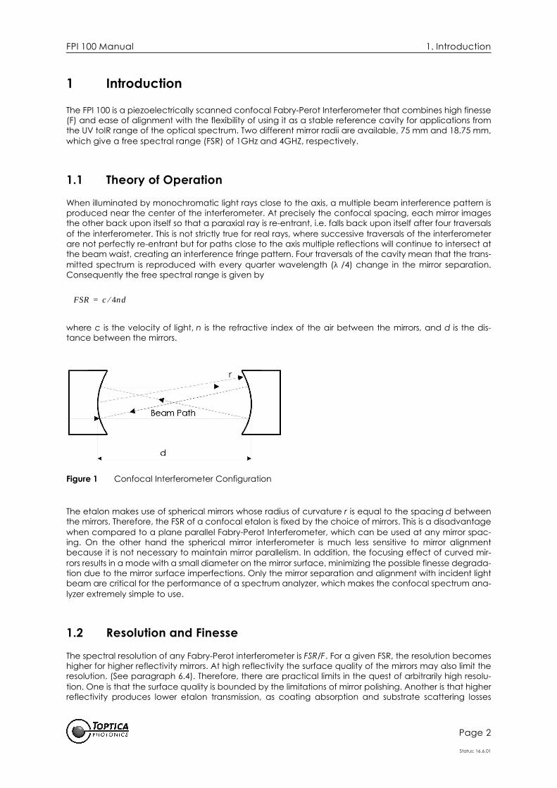
When illuminated by monochromatic light rays close to the axis, a multiple beam interference pattern isproduced near the center of the interferometer. At precisely the confocal spacing, each mirror imagesthe other back upon itself so that a paraxial ray is re-entrant, i.e. falls back upon itself after four traversalsof the interferometer. This is not strictly true for real rays, where successive traversals of the interferometerare not perfectly re-entrant but for paths close to the axis multiple reflections will continue to intersect atthe beam waist, creating an interference fringe pattern. Four traversals of the cavity mean that the trans-mitted spectrum is reproduced with every quarter wavelength (λ /4) change in the mirror separation.Consequently the free spectral range is given by
where c is the velocity of light, n is the refractive index of the air between the mirrors, and d is the dis-tance between the mirrors.
Figure 1 Confocal Interferometer Configuration
The etalon makes use of spherical mirrors whose radius of curvature r is equal to the spacing d betweenthe mirrors. Therefore, the FSR of a confocal etalon is fixed by the choice of mirrors. This is a disadvantagewhen compared to a plane parallel Fabry-Perot Interferometer, which can be used at any mirror spac-ing. On the other hand the spherical mirror interferometer is much less sensitive to mirror alignmentbecause it is not necessary to maintain mirror parallelism. In addition, the focusing effect of curved mir-rors results in a mode with a small diameter on the mirror surface, minimizing the possible finesse degrada-tion due to the mirror surface imperfections. Only the mirror separation and alignment with incident lightbeam are critical for the performance of a spectrum analyzer, which makes the confocal spectrum ana-lyzer extremely simple to use.
1.2 Resolution and Finesse
The spectral resolution of any Fabry-Perot interferometer is FSR/F. For a given FSR, the resolution becomeshigher for higher reflectivity mirrors. At high reflectivity the surface quality of the mirrors may also limit theresolution. (See paragraph 6.4). Therefore, there are practical limits in the quest of arbitrarily high resolu-tion. One is that the surface quality is bounded by the limitations of mirror polishing. Another is that higherreflectivity produces lower etalon transmission, as coating absorption and substrate scattering losses
FSR c 4nd⁄=

FPI 100 Manual 1. Introduction
Page 3
Status: 16.6.01
become magnified by a factor of (1-R)-1. Finesse as high as 105 has been reported for super-polished sub-strates with low-loss coatings. However, such mirrors are environmentally sensitive, and are usuallymounted in hermetically sealed housings.
By contrast, the FPI 100 uses mirrors with moderately high reflectivity (> 99,7%), which can be pro-duced in almost any spectral region between 350 and 1700 nm with losses low enough for high interfer-ometer transmission.
By request the FPI 100 can also be supplied with interchangeable mirrors. Changing to another spec-tral region usually requires only an internal mirror change and the adaption of the mirror spacings ratherthan a complete etalon change.
The FPI 100 is intended as a spectral analysis system as well as a stable reference cavity. Its resolutiondepends on the quality of the mirror coating and surface and is separately specified for each interferom-eter. A typical resolution is 5 MHz by using a mirror set having a free spectral range of 1GHz and a finesseof 200. In applications requiring a high long-term absolute stability the FPI 100 can also be temperaturestabilized.
Typical applications of the spectrum analyzer include mode structure characterization, the measure-ment of laser linewidths, laser frequency stability and the frequency stabilization of lasers.
Optical spectrum analyzers are commonly used with almost every type of laser. Please contactTOPTICA Photonics AG for further information about Fabry-Perot applications and operating principles.

FPI 100 Manual 2. Inspection after Delivery
Page 4
Status: 16.6.01
2 Inspection after Delivery
The FPI 100 is packed in a carton designed to give maximum protection during shipment. If the outside ofthe shipping carton is damaged, notify your shipping department immediately. The shipping departmentmay wish to notify the carrier at this point.
If the shipping carton is undamaged externally, the instrument should be removed from the carton. Ifany damage is evident visually or if any rattling can be heard if the unit is shaken lightly, notifyTOPTICA Photonics AG and your shipping department. It is advisable to save the carton for future storageor transportation.
The complete system consists of the Parts shown in Figure 2.
Figure 2 The FPI 100 System
(1) FPI Assembly (etalon body with mounted mirror on a PZT, resonator adjustment body withmounted mirror, cover plate
(2) Photodetector housing with mounted photodiode and cable connecting the photodetector withan oscilloscope or a detector amplifier
(3) Baseplate(4) Post(5) Additional set of mirrors (optional)(6) SMB cable for driving the piezoelectric actuator and connecting the Scan Control SC 100 to the
FPI 100(7) Fiber Coupling Adaptor (optional)
The FPI contains the mirror set specified on the order.The instrument you have received has been fully tested at the factory prior to shipment and meets allspecifications. As with any optical instrument it is important that it is maintained in a clean state.

FPI 100 Manual 2. Inspection after Delivery
Page 5
Status: 16.6.01
In some cases optional accessories are supplied with the FPI 100.
Scan Control SC 100
Figure 3 Scan Control SC 100 (optional)
PDA 100
Figure 4 Photo Diode Amplifier PDA 100 (optional)
FPI 100 Manual 3. Description of Components of the FPI 100 System
Page 6
Status: 16.6.01
3 Description of Components of the FPI 100 System
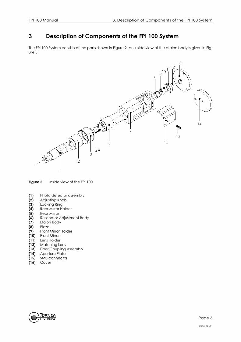
The FPI 100 System consists of the parts shown in Figure 2. An inside view of the etalon body is given in Fig-ure 5.
Figure 5 Inside view of the FPI 100
(1) Photo detector assembly(2) Adjusting Knob(3) Locking Ring(4) Rear Mirror Holder(5) Rear Mirror(6) Resonator Adjustment Body(7) Etalon Body(8) Piezo(9) Front Mirror Holder(10) Front Mirror(11) Lens Holder(12) Matching Lens(13) Fiber Coupling Assembly(14) Aperture Plate(15) SMB-connector(16) Cover
FPI 100 Manual 3. Description of Components of the FPI 100 System
Page 7
Status: 16.6.01
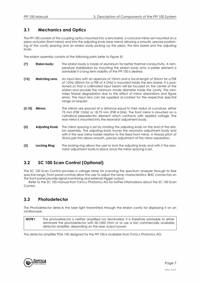
3.1 Mechanics and Optics
The FPI 100 consists of the coupling optics mounted into a lens barrel, a concave mirror set mounted on apiezo actuator (front mirror) and into the adjusting knob (rear mirror) allowing a smooth, precise position-ing of the cavity spacing and an etalon body picking up the piezo, the lens barrel and the adjustingknob.
The etalon assembly consists of the following parts (refer to Figure 5):
(7) Etalon body: The etalon body is made of aluminium for better thermal conductivity. A tem-perature stabilization by mounting the etalon body onto a peltier element isadvisable if a long term stability of the FPI 100 is desired.
(12) Matching Lens: An input lens with an aperture of 10mm and a focal length of 50mm for a FSRof 1GHz (30mm for a FSR of 4 GHz) is mounted inside the lens barrel. It is posi-tioned so that a collimated input beam will be focused on the center of theetalon and provide the minimum mode diameter inside the cavity. This mini-mizes finesse degradation due to the effect of mirror aberrations and figureerrors. The input lens can be supplied ar-coated for the respective spectralrange on request.
(5,10) Mirrors: The mirrors are spaced at a distance equal to their radius of curvature, either75 mm (FSR 1GHz) or 18,75 mm (FSR 4 GHz). The front mirror is mounted on acylindrical piezoelectric element which contracts with applied voltage. Therear mirror is mounted into the resonator adjustment body.
(2) Adjusting Knob: The mirror spacing is set by rotating the adjusting knob on the end of the eta-lon assembly. The adjusting knob moves the resonator adjustment body andwith it the rear mirror holder relative to the fixed front mirror. A thread pitch of3turns per mm allows smooth, precise adjustment of the mirror separation.
(3) Locking Ring: The locking ring allows the user to lock the adjusting knob and with it the reso-nator adjustment body in place once the mirror spacing is set.
3.2 SC 100 Scan Control (Optional)
The SC 100 Scan Control provides a voltage ramp for scanning the spectrum analyzer through its freespectral range. Front panel controls allow the user to adjust the ramp characteristics. BNC connectors onthe front panel provide signal monitoring and external trigger output.
Refer to the SC 100 manual from TOPTICA Photonics AG for further informations about the SC 100 ScanControl.
3.3 Photodetector
The Photodetector detects the laser light transmitted through the etalon cavity for displaying it on anoscilloscope.
The detector amplifier PDA 100 designed for the FPI 100 is available from TOPTICA Photonics AG.
NOTE ! The photodetector is neither amplified nor terminated. It is therefore advisable to eitherterminate the photodetector with 50-1000 Ohm or to use a fast commercially availabledetector amplifier, depending on the laser output power.

FPI 100 Manual 4. Operation
Page 8
Status: 16.6.01
4 Operation
4.1 Electronic Setup
• Connect the output ramp of the ramp generator to the FPI 100 using the SMB-connector on the etalon body.
• Connect a BNC cable from the output ramp of the ramp generator to an oscilloscope input.• Connect a BNC cable from the trigger output of the ramp generator to the oscilloscope trigger.• Connect the photodetector to an oscilloscope input using the BNC cable provided with the
FPI 100.
Start operating the SC 100 (or similar ramp generator). Set the ramp duration to a low value of about 20milliseconds. Adjust the amplitude and voltage offset so that a ramp of at least 30 V pp is displayed onthe oscilloscope without being clipped. These settings produce at least one interferometer free spectralrange displayed on the oscilloscope.
4.2 Optical Alignment
The FPI 100 is designed for excellent resolution and stability. The most important factor in fully realizingthese features is careful alignment of the etalon. The following instructions assume a stable, single fre-quency laser. Although it is not a requirement for proper alignment, a stable, single frequency is the mostconvenient source for alignment, particularly for the first time user, because it produces only one peakper free spectral range.
Once the preliminary electronic settings of the preceding section are complete, the next step is toalign the laser to the etalon. Note that the detector can remain attached to the spectrum analyzer dur-ing these adjustments because it is flexible with respect to the cable supplied with the FPI 100.
4.2.1 Coarse Cavity Adjustment
First make sure that the interferometer assembly is complete (see Figure 5). Although the etalon isshipped factory-aligned, it may be necessary to slightly adjust the mirror spacing. This is also necessaryafter changing mirror sets.
Align the laser beam so that it is traveling parallel to the optical table or surface on which the FPI 100is mounted. Use a mirror or a mirror pair in order to center the laser beam on the aperture of the FPI 100.Now adjust the laser beam by using the above mirror pair so that the light reflected from the etalon mir-rors is directed back onto the incident beam. Directing the incident beam through a small aperture in awhite viewing card placed about 30 cm in front of the etalon will aid in viewing and aligning thereflected beam. Using an infrared laser implies either using a infrared camera or a infrared sensor card inorder to monitor the alignment.
It should now be possible to see a signal on the oscilloscope. By comparing this signal with the signalsin Figure 7 through Figure 13 a coarse estimation about the necessary alignment should be possible.
If no signal seen, refer to Paragraph 5, Troubleshooting.
NOTE ! The voltage output ramp should not exceed 0-500 V!
FPI 100 Manual 4. Operation
Page 9
Status: 16.6.01
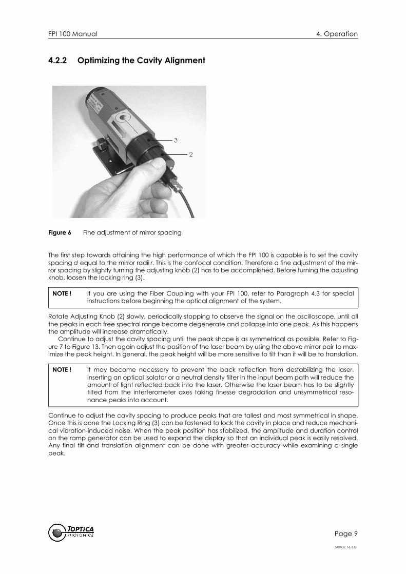
4.2.2 Optimizing the Cavity Alignment
Figure 6 Fine adjustment of mirror spacing
The first step towards attaining the high performance of which the FPI 100 is capable is to set the cavityspacing d equal to the mirror radii r. This is the confocal condition. Therefore a fine adjustment of the mir-ror spacing by slightly turning the adjusting knob (2) has to be accomplished. Before turning the adjustingknob, loosen the locking ring (3).
Rotate Adjusting Knob (2) slowly, periodically stopping to observe the signal on the oscilloscope, until allthe peaks in each free spectral range become degenerate and collapse into one peak. As this happensthe amplitude will increase dramatically.
Continue to adjust the cavity spacing until the peak shape is as symmetrical as possible. Refer to Fig-ure 7 to Figure 13. Then again adjust the position of the laser beam by using the above mirror pair to max-imize the peak height. In general, the peak height will be more sensitive to tilt than it will be to translation.
Continue to adjust the cavity spacing to produce peaks that are tallest and most symmetrical in shape.Once this is done the Locking Ring (3) can be fastened to lock the cavity in place and reduce mechani-cal vibration-induced noise. When the peak position has stabilized, the amplitude and duration controlon the ramp generator can be used to expand the display so that an individual peak is easily resolved.Any final tilt and translation alignment can be done with greater accuracy while examining a singlepeak.
NOTE ! If you are using the Fiber Coupling with your FPI 100, refer to Paragraph 4.3 for specialinstructions before beginning the optical alignment of the system.
NOTE ! It may become necessary to prevent the back reflection from destabilizing the laser.Inserting an optical isolator or a neutral density filter in the input beam path will reduce theamount of light reflected back into the laser. Otherwise the laser beam has to be slightlytilted from the interferometer axes taking finesse degradation and unsymmetrical reso-nance peaks into account.

FPI 100 Manual 4. Operation
Page 10
Status: 16.6.01
As one continues to improve the signal from the spectrum analyzer, one frequently achieves the condi-tion of partial mode matching. Partial mode matching will cause the peaks in adjacent free spectralranges to be of unequal intensity. There is no problem with operating in this condition so long as one isaware that the weaker signal is simply the next interferometer order, and not a second frequency in thelaser output. When the interferometer is completely mode matched, the FSR doubles and the peakheight also doubles. See Appendix A for more information and mode matching.
Figure 13 shows a portion of one FSR obtained with a properly aligned FPI 100 System. The source wasa grating stabilized single mode diode laser working at 780 nm.
4.2.3 Interferometer Spectres
Figure 7 Cavity Spacing is too large by 1 mm.
Figure 8 Cavity Spacing is too large by 0.6 mm corresponding to two turns of the Adjusting Knob.

FPI 100 Manual 4. Operation
Page 11
Status: 16.6.01
Figure 9 Cavity Spacing is too large by 0.3 mm corresponding to one turn of the Adjusting Knob.
Figure 10 Cavity Spacing is too large by 0.15 mm corresponding to a half turn of the Adjusting Knob.

FPI 100 Manual 4. Operation
Page 12
Status: 16.6.01
Figure 11 Cavity Spacing is too large by 0.075 mm corresponding to a quarter turn of the Adjusting Knob.
Figure 12 Cavity Spacing is almost perfect (d = r). The Locking Screws should now be fastened. The two modes are separated by 1 GHz corresponding to the free spectral range of the FPI 100.

FPI 100 Manual 4. Operation
Page 13
Status: 16.6.01
Figure 13 The Finesse is computed by comparison with Figure 12 and taking the free spectral range into account. The laser used for the measurement had a wavelenght of 780 nm. The photodetec-tor was terminated by 50 Ohms and the signal amplified by 104.

FPI 100 Manual 4. Operation
Page 14
Status: 16.6.01
4.3 Fiber Coupling Mounting and Alignment
For exchanging the aperture plate to the fiber coupling assembly and collimation of the laser beam fol-low the steps given below.
1. Unscrew screws 1-3 (see Figure 14) and remove aperture plate.
Figure 14 Aligning and mounting fiber coupling assembly
2. For optimum coupling to the interferometer, the input beam propagating through the fiber cou-pling assembly should be collimated by adjusting the position of the collimating lens. To checkwhether the laser beam is properly collimated, connect fiber cable to fiber coupling assembly,switch on laser and observe laser beam in distances from 1 to 6 m. For collimating beam adjustcollimating lens by the aid of tweezers.
3. Mount fiber coupling assembly to the etalon body by fixing screws 1-3.
It should now be possible to see a signal on the oscilloscope. The alignment can then be optimized by tilt-ing the fiber coupling assembly using the six screws at its front.
If no signal detected, the collimation of the laser beam after the fiber coupling assembly should beinvestigated and readjusted if necessary.
NOTE ! Before using the fiber option make sure that the mirror spacing is optimized (see para-graph 4.2.2). In order to achieve the best performance of the FPI 100 it is advisable to usea single mode fiber to couple the laser into the interferometer. However, a quiet good per-formance is also possible by using a multi-mode fiber.
DANGER ! Do not look into the laser beam under conditions with exceed the limits specified by theUnited States Food and Drug Administration, Department of Health and Human Services,Center for Devices and Radiological Health, 21 CFR 1040.10 and 2 CFR 1040.11. Take pre-cautions to eliminate exposure to a direct or reflected beam. When carrying out adjust-ments always wear laser safety goggles.
FPI 100 Manual 4. Operation
Page 15
Status: 16.6.01
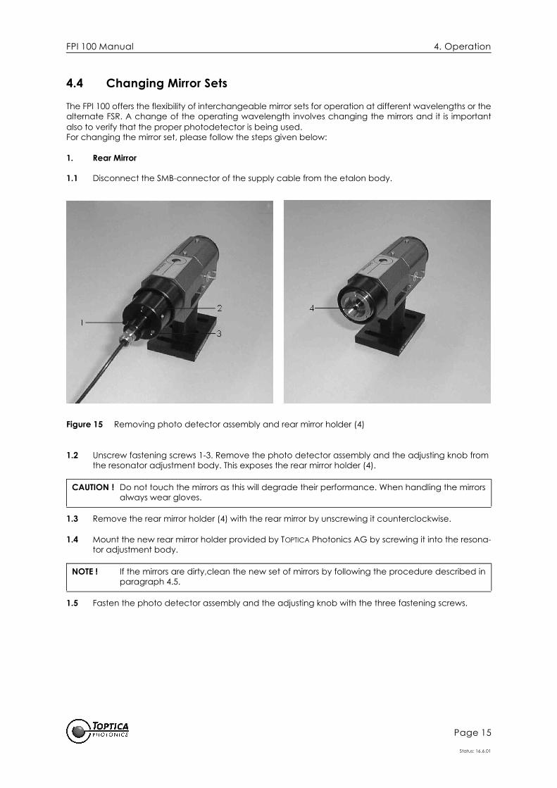
4.4 Changing Mirror Sets
The FPI 100 offers the flexibility of interchangeable mirror sets for operation at different wavelengths or thealternate FSR. A change of the operating wavelength involves changing the mirrors and it is importantalso to verify that the proper photodetector is being used.For changing the mirror set, please follow the steps given below:
1. Rear Mirror
1.1 Disconnect the SMB-connector of the supply cable from the etalon body.
Figure 15 Removing photo detector assembly and rear mirror holder (4)
1.2 Unscrew fastening screws 1-3. Remove the photo detector assembly and the adjusting knob from the resonator adjustment body. This exposes the rear mirror holder (4).
1.3 Remove the rear mirror holder (4) with the rear mirror by unscrewing it counterclockwise.
1.4 Mount the new rear mirror holder provided by TOPTICA Photonics AG by screwing it into the resona-tor adjustment body.
1.5 Fasten the photo detector assembly and the adjusting knob with the three fastening screws.
CAUTION ! Do not touch the mirrors as this will degrade their performance. When handling the mirrorsalways wear gloves.
NOTE ! If the mirrors are dirty,clean the new set of mirrors by following the procedure described inparagraph 4.5.

FPI 100 Manual 4. Operation
Page 16
Status: 16.6.01
2. Front Mirror
Figure 16 Removing fiber coupling assembly and front mirror holder
2.1 Remove the fiber coupling assembly (or the aperture plate) by unscrewing screws 5 - 7.
Figure 17 Removing lens holder (8) and front mirror holder (10)
2.2 Open side cover of FPI 100. Loosen fixing screw (9) and remove lens holder (8). Remove front mir-ror holder (10) with the front mirror by unscrewing it from the piezo.
CAUTION ! Do not touch the mirrors as this will degrade their performance. When handling the mirrorsalways wear gloves.

FPI 100 Manual 4. Operation
Page 17
Status: 16.6.01
2.3 Mount the new front mirror holder provided by TOPTICA Photonics AG by screwing it onto the piezo.
2.4 Check to make sure that your detector and matching lens are appropriate for use with the new mirror set. (see specification tables in paragraph 6.1)
2.5 Screw the lens holder into the etalon body to the position shown in Figure 18 and fix with screw (9).
Figure 18 Recommended position of lens holder
2.6 Fix the fiber coupling assembly or aperture plate with the three screws.
4.4.1 Changing free spectral range
The FPI 100 system is designed for a FSR of 1 GHz. It is however also possible to provide a FSR of 4 GHz bychanging the mirror sets and the focusing lens. Please contact TOPTICA Photonics AG for this option.
NOTE ! If the mirrors are dirty,clean the new set of mirrors by following the procedure described inparagraph 4.5.
NOTE ! The position of the lens holder (8) is optimized for collimated laser beams and is indepen-dent from the coating of the mirrors.
NOTE ! It will normaly be necessary to readjust the resonator length after having changed the mir-ror set due to slight differences of the mirror positions.

FPI 100 Manual 4. Operation
Page 18
Status: 16.6.01
4.5 Cleaning of mirrors
1. Remove both mirrors from the FPI 100. See paragraph 4.4 for instructions. Blow all dust from the coated surface of the mirrors using clean, dry gas.
2. Fold a piece of lens tissue several times to produce a pad 10 - 20 layers thick and approximately the size of the mirrors. Hold the pad in a locking hemostat.
3. Use spectral grade acetone to saturate the pad of lens tissue and then shake the excess off. Repeat this at least twice.
4. Carefully brush the pad of lens tissue across the coated surface of the of one mirror once and then discard it. Produce a new pad of lens tissue and clean the other mirror.
5. The mirrrors should now be clean and there should not be a pool of acetone remaining in the cen-ter of either mirror. If the mirrors are still dirty, or a pool of acetone has collected on either mirror, repeat the cleaning process.
6. Mount mirrors into FPI 100 according to instructions in paragraph 4.4.
NOTE ! It is neither necessary nor desirable to clean the mirrors every time they are changed. Ifstored in their containers and used only in clean environment the mirrors may never needcleaning.

FPI 100 Manual 5. Troubleshooting
Page 19
Status: 16.6.01
5 Troubleshooting
SYMPTOM POSSIBLE CAUSES/REMEDIES
Etalon does not scan
Check for defective or damaged electrical connection with the SC 100 or similar ramp generator.
No ramp The power supply or the PZT may be damaged - call TOPTICA Customer Service. If the ramp signal reappears when the PZT cable is disconnected at the etalon end, there is probably a short in the PZT.
No detector signal The optical alignment may not be close enough. This is especially true for infra-red beams where it is hard to see the beam location. It may be helpful to system-atically sweep the translation controls of the etalon mount to search for a signal. Check to see if the beam is retro-reflected from the etalon.
The laser power may be to low and the beam size and focus position too far from the optimum to raise the signals above the noise. For weak infrared beams it may be necessary to first align a visible laser to be collinear with the infrared beam and align the FPI 100 with the visible beam.
Look for a broken detector lead, improperly installed detector, or incorrect detector. Check the detector functions by removing the detector housing from the adjusting knob and exposing the detector to a light source (room lights, or the source laser beam).
Blown fuse Call TOPTICA Customer Service.
Low finesse The laser wavelength my be outside the mirror´s high reflectivity range or the laser linewidth may be to large. Check the transmission curve provided with the etalon mirrors of the spectral range.
The photodetector bandwidth may be too low for the ramp generator scan duration or amplitude. Make sure that the photodetector is terminated with 50-1000 Ohm and use a detector amplifier if necessary.
The mirrors could be dirty or the coatings may have been damaged. Visually inspect the mirrors for dirt and damage and clean if necessary. If coating dam-age is suspected, contact the TOPTICA Customer Service Department.
Excessive mode noise, peaks jump randomly
Mechanical vibration coupled to the FPI 100. Remove the source of vibration, isolate FPI 100, and/or tighten the locking screws.
The back reflection from the etalon may be causing instability in the source laser. Install an optical isolator or place beamsplitter, neutral density filter, or other opti-cal attenuator in the beam path or tilt the cavity (or laser beam) some degrees away from its initial alignment.
FPI 100 Manual 5. Troubleshooting
Page 20
Status: 16.6.01
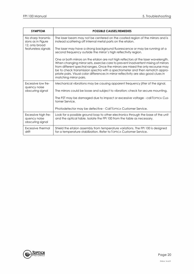
No sharp transmis-sions as in Figure 12, only broad featureless signals
The laser beam may not be centered on the coated region of the mirrors and is instead scattering off internal metal parts on the etalon.
The laser may have a strong background fluorescence or may be running at a second frequency outside the mirror´s high reflectivity region.
One or both mirrors on the etalon are not high reflectors at the laser wavelength. When changing mirror sets, exercise care to prevent inadvertent mixing of mirrors from different spectral ranges. Once the mirrors are mixed the only recourse may be to check transmission spectra with a spectrometer and then rematch appro-priate pairs. Visual color differences in mirror reflectivity are also good clues in matching mirror pairs.
Excessive low fre-quency noise obscuring signal
Mechanical vibrations may be causing apparent frequency jitter of the signal.
The mirrors could be loose and subject to vibration; check for secure mounting.
The PZT may be damaged due to impact or excessive voltage - call TOPTICA Cus-tomer Service.
Photodetector may be defective - Call TOPTICA Customer Service.
Excessive high fre-quency noise obscuring signal
Look for a possible ground loop to other electronics through the base of the unit and the optical table. Isolate the FPI 100 from the table as necessary.
Excessive thermal drift
Shield the etalon assembly from temperature variations. The FPI 100 is designed for a temperature stabilization. Refer to TOPTICA Customer Service.
SYMPTOM POSSIBLE CAUSES/REMEDIES

FPI 100 Manual 6. Appendix
Page 21
Status: 16.6.01
6 Appendix
6.1 Specifications
Interferometer Specifications
Cavity Design: Confocal spherical mirrorsFSR: 1 GHz or 4 GHzFinesse: >100 over specified wavelength range (>300 by request)Coating Ranges Available: 380 to 1700 nmInput Clear Aperture: 5 mmDimensions: 174,5 x 40 x 46,6 mmEtalon Body: Aluminium and PZT cavity constructionAdjusting Knob POMThermal Sensitivity: 7µm/°CMinimum Input Power: 10 µW bei 633 nm, Amplitude = 200 mV
PZT Specifications
Piezoelectric Scan: 1µm/100 VoltPZT Capacitance: 50 nFPZT Maximum Voltage: 500 Volt
Mode Matching Lens
Type: biconvexFocal Distance f: 50 mm for FSR 1 GHz (30 mm for FSR 4 GHz)AR Coating: None (only on request)
Fiber Coupler Lens
Type: MultilensFocal Distance: 4.5 mmNumerical Aperture: 0.47AR Coatings: @ 630, 780 and 1400 nm
Photodetectors
Matching Lens Radius of Mirror
FSR 1 GHz f = 50 mm 75 mm
FSR 4 GHz f = 30 mm 18.75 mm
λ λ [nm] Detector
380 - 1000 Si-Detector
1000 - 1700 InGaAs-Detector

FPI 100 Manual 6. Appendix
Page 22
Status: 16.6.01
6.2 Main Dimensions of FPI 100
Figure 19 FPI 100 Main Dimensions

FPI 100 Manual 6. Appendix
Page 23
Status: 16.6.01
6.3 Modes of a Spherical Mirror Interferometer
The general expression for the modal frequencies of spherical mirror interferometers was derived by Boydand Kogelnick1 as
In this expression q, m, and n are positive integers, where q refers to the axial mode number; m and nrefer to transverse modes. For plane mirrors the radius is infinite; while for confocal systems r = d. Thus theresonance frequencies are multiples of c/2d for the plane case, and c/4d for the confocal.
When r = d, the confocal condition, all the odd modes are degenerate and distinct from all the evenmodes, which are also degenerate. Furthermore, the even modes overlap the axial modes, while theodd modes transmit exactly half way between. This situation is termed a mode-degenerate interferome-ter and is a very useful configuration since if the incoming laser excites higher order transverse modes,the only „penalty“ is that the FSR is halved but the interferometer has no spurious transmissions. This is thenormal operating mode of the FPI 100.
When r ≠ d, as is the case during alignment of the mirror spacing in the etalon, additional modes willappear since it is not mode-degenerate. Here even a single frequency input will produce a multiplepeak transmission signal unless the higher order transverse modes are not excited. Excitation of only thelowest order transverse modes (m and n both equal to zero) is called mode-matching and produces atransmission with a FSR equal to the plane mirror value of c/2d for any values of r and d.
6.4 Finesse
The mirror finesse of the FPI 100 Interferometer may be partitioned into contributions from reflectivity (FR)and surface imperfections (FS). The overall instrument finesse (F I) is determined by the parallel combina-tion of these terms through the relation.
The reflectivity finesse is determined by the mirror reflectivity (R) according to
This relation is valid for a non mode-matched confocal system. For either plane mirrors or for mode-matched curved mirrors of any radius FR is approximately twice the value given by the above formula.
In order to have a finesse of 300, it is therefore necessary to have a reflectivity of al least 99.5%. Thisvalue is far below the maximum attainable for state of the art coatings, for which reflectivities of 99.99%are possible. Since reflectivity is not the sole determinant of finesse, it is obvious that there is an optimumreflectivity which is less than the maximum in cases where the surface finesse is not infinite.
The surface finesse is a measure of how closely the mirror substrate approximates the ideal geometricspherical segment. On a microscopic scale surface roughness implies that the optical distance betweenthe mirrors is not constant for adjacent regions of the mirror surface. From the resonance condition thismeans that there will be a distribution of transmissions centered about the mean. Such a spread is equiv-
1. G.D. Boyd and H. Kogelnick, Bell Syst. Tech. J. 41:1347 (1962)
ν c2d------ q 1
π--- 1 m n+ +( ) 1 d
r---–
1–cos+=
FI2–
FR2–
FS2–
+=
FRπR
1 R2
–( )
12---
----------------------=

FPI 100 Manual 6. Appendix
Page 24
Status: 16.6.01
alent to a broadened transmission or a reduced finesse. With standard polishing techniques, surfaceroughness of 20 Å is achievable while for so-called „super polishing“ methods this value may be reducedby an order of magnitude. The surface finesse implied by these roughness values varies between 104 and105. Consequently, „super polishing“ is unnecessary for an instrument finesse in the neighborhood of 103,but is essential for one in excess of 104.
Another potential complication of using a too high reflectivity is reduced instrument transmission (T).As reflectivity increases, the mirror losses due to absorption and scattering become amplified and theinstrument transmission decreases according to the equation for a confocal interferometer,
where A is the sum of the absorption and scattering losses.Standard optical coatings can have losses in the range of 200 to 1000 ppm, while the best state of the
art coatings have losses as low as 20 ppm. Unfortunately, such super coatings are expensive and are notavailable in all spectral ranges.
The FPI 100 mirrors generally use reflectivities of about 99.7% to achieve a finesse in excess of 300 anda transmission of greater than 10%. These mirrors are available in virtually every spectral range. Whilehigher reflectivities may be used without problem in the FPI 100 etalon, the transmission will begin todecrease and the finesse will not increase as rapidly as one approaches limits set by mirror absorptionand substrate polishing.
T 12--- 1 A
1 R–------------–
2=